WO2019208458A1 - 加熱調理器 - Google Patents
加熱調理器 Download PDFInfo
- Publication number
- WO2019208458A1 WO2019208458A1 PCT/JP2019/016914 JP2019016914W WO2019208458A1 WO 2019208458 A1 WO2019208458 A1 WO 2019208458A1 JP 2019016914 W JP2019016914 W JP 2019016914W WO 2019208458 A1 WO2019208458 A1 WO 2019208458A1
- Authority
- WO
- WIPO (PCT)
- Prior art keywords
- heating chamber
- illumination
- heating
- opening
- upper wall
- Prior art date
- Legal status (The legal status is an assumption and is not a legal conclusion. Google has not performed a legal analysis and makes no representation as to the accuracy of the status listed.)
- Ceased
Links
Images


Classifications
-
- F—MECHANICAL ENGINEERING; LIGHTING; HEATING; WEAPONS; BLASTING
- F24—HEATING; RANGES; VENTILATING
- F24C—DOMESTIC STOVES OR RANGES ; DETAILS OF DOMESTIC STOVES OR RANGES, OF GENERAL APPLICATION
- F24C15/00—Details
- F24C15/008—Illumination for oven cavities
-
- F—MECHANICAL ENGINEERING; LIGHTING; HEATING; WEAPONS; BLASTING
- F24—HEATING; RANGES; VENTILATING
- F24C—DOMESTIC STOVES OR RANGES ; DETAILS OF DOMESTIC STOVES OR RANGES, OF GENERAL APPLICATION
- F24C15/00—Details
- F24C15/004—Windows not in a door
-
- F—MECHANICAL ENGINEERING; LIGHTING; HEATING; WEAPONS; BLASTING
- F24—HEATING; RANGES; VENTILATING
- F24C—DOMESTIC STOVES OR RANGES ; DETAILS OF DOMESTIC STOVES OR RANGES, OF GENERAL APPLICATION
- F24C7/00—Stoves or ranges heated by electric energy
- F24C7/04—Stoves or ranges heated by electric energy with heat radiated directly from the heating element
- F24C7/046—Ranges
-
- F—MECHANICAL ENGINEERING; LIGHTING; HEATING; WEAPONS; BLASTING
- F24—HEATING; RANGES; VENTILATING
- F24C—DOMESTIC STOVES OR RANGES ; DETAILS OF DOMESTIC STOVES OR RANGES, OF GENERAL APPLICATION
- F24C7/00—Stoves or ranges heated by electric energy
- F24C7/08—Arrangement or mounting of control or safety devices
- F24C7/082—Arrangement or mounting of control or safety devices on ranges, e.g. control panels, illumination
- F24C7/085—Arrangement or mounting of control or safety devices on ranges, e.g. control panels, illumination on baking ovens
-
- H—ELECTRICITY
- H05—ELECTRIC TECHNIQUES NOT OTHERWISE PROVIDED FOR
- H05B—ELECTRIC HEATING; ELECTRIC LIGHT SOURCES NOT OTHERWISE PROVIDED FOR; CIRCUIT ARRANGEMENTS FOR ELECTRIC LIGHT SOURCES, IN GENERAL
- H05B6/00—Heating by electric, magnetic or electromagnetic fields
- H05B6/64—Heating using microwaves
- H05B6/6444—Aspects relating to lighting devices in the microwave cavity
-
- H—ELECTRICITY
- H05—ELECTRIC TECHNIQUES NOT OTHERWISE PROVIDED FOR
- H05B—ELECTRIC HEATING; ELECTRIC LIGHT SOURCES NOT OTHERWISE PROVIDED FOR; CIRCUIT ARRANGEMENTS FOR ELECTRIC LIGHT SOURCES, IN GENERAL
- H05B6/00—Heating by electric, magnetic or electromagnetic fields
- H05B6/64—Heating using microwaves
- H05B6/6447—Method of operation or details of the microwave heating apparatus related to the use of detectors or sensors
-
- F—MECHANICAL ENGINEERING; LIGHTING; HEATING; WEAPONS; BLASTING
- F24—HEATING; RANGES; VENTILATING
- F24C—DOMESTIC STOVES OR RANGES ; DETAILS OF DOMESTIC STOVES OR RANGES, OF GENERAL APPLICATION
- F24C7/00—Stoves or ranges heated by electric energy
- F24C7/02—Stoves or ranges heated by electric energy using microwaves
Definitions
- the present invention relates to a cooking device that heats food.
- heating cooker having a photographing unit for photographing the interior (see, for example, Patent Document 1).
- This heating cooker has an imaging unit on the ceiling of the heating cabinet and is equipped with illumination that increases the amount of light in order to stabilize imaging.
- the cooking device includes a heating chamber having a front opening and a heating unit that heats an object to be heated stored in the heating chamber.
- the heating cooker has an optical axis that is inclined with respect to the vertical direction, a camera disposed on the upper wall of the heating chamber so as to face the heating chamber, and a heating chamber from the upper wall side of the heating chamber.
- First illumination that illuminates inward.
- the heating cooker is disposed below the upper wall of the heating chamber, and is formed of a translucent member so as to diffuse light from the first illumination and illuminate the lower side, and the camera is also connected to the heating chamber.
- a top plate portion provided with a top plate opening which is an opening for photographing the inside.
- the present disclosure can suppress halation by arranging the photographing unit on the upper surface in the cabinet to be inclined and providing soft surface illumination on the upper surface in the chamber. Thereby, the imaging
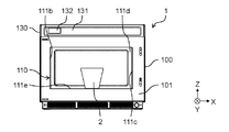
- FIG. 1 is a perspective view of a heating cooker according to an aspect of the present disclosure.
- Drawing 2 is a perspective view showing the state where the door of the cooking-by-heating machine concerning one mode of this indication was opened.
- Drawing 3 is a front view showing the state where the door of the cooking-by-heating machine concerning one mode of this indication was removed.
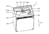
- Drawing 4 is a perspective view from the lower part showing the state where the door of the cooking-by-heating machine concerning one mode of this indication was removed.
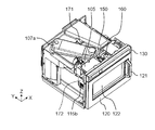
- FIG. 5 is a perspective view illustrating a state where a part of the casing of the heating cooker according to one aspect of the present disclosure is removed.
- FIG. 6 is a top view illustrating a state where a part of the casing of the heating cooker according to one aspect of the present disclosure is removed.
- FIG. 7 is a cross-sectional view taken along the line 7-7 in FIG. 8 is a cross-sectional view taken along the line 8-8 in FIG. 9 is a cross-sectional view taken along line 9-9 of FIG. 10 is a cross-sectional view taken along the line 10-10 in FIG.
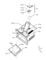
- FIG. 11 is an exploded perspective view of main components of the cooking device according to one aspect of the present disclosure.
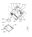
- FIG. 12 is an exploded perspective view of the main parts of the cooking device according to one aspect of the present disclosure as viewed from below.
- Drawing 13 is an explanatory view in the upper surface view explaining the composition of the cooking-by-heating machine concerning one mode of this indication.
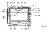
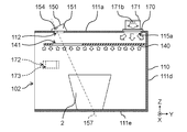
- FIG. 14 is an explanatory diagram in a front view illustrating the configuration of the heating cooker according to one aspect of the present disclosure.
- FIG. 15 is an explanatory diagram in a side view illustrating the configuration of the heating cooker according to one aspect of the present disclosure.
- FIG. 16 is an explanatory diagram in a side view illustrating the configuration of the heating cooker according to one aspect of the present disclosure.
- FIG. 17 is an explanatory diagram in a side view illustrating the configuration of the heating cooker according to one aspect of the present disclosure.
- the heating cooker 1 includes a housing 100, a heating chamber 110 disposed in the housing 100, and a front frame serving as a front surface of the housing 100. And a door 120 that covers the front opening 102 located at 101 so as to be openable and closable.
- the front opening 102 side of the heating cooker 1 is the front side, and the back side on the opposite side is the rear side. Further, when viewed from the front side, that is, in a front view, the top surface side of the heating cooker 1 is the upper side, and the bottom surface side is the lower side. Furthermore, in the front view, the right direction of the heating cooker 1 is the right side, and the left direction is the left side.
- the right direction is the X direction and the left direction is the -X direction.
- the backward direction of the cooking device 1 is defined as the Y direction, and the forward direction is defined as the -Y direction.
- the upper direction of the heating cooker 1 is the Z direction, and the lower direction is the -Z direction.
- the heating chamber 110 includes an upper wall 111a disposed at the top, a left wall 111b and a right wall 111c disposed on both left and right sides, a back wall 111d disposed at the rear, and a bottom wall 111e disposed at the bottom. And a space is formed in the interior.
- the door 120 is attached to the housing 100 so as to be openable and closable at the center of the vertical rotation on the left side of the front opening 102.
- the door 120 has a handle 121 at the right end of the front surface. When the user pulls the handle 121, the door 120 is rotated and the front opening 102 is opened. Further, when the user pushes the handle 121, the front opening 102 is closed.
- the door 120 is provided with a glass window 122 so that the user can check the situation inside the heating chamber 110.
- a horizontally long operation unit 130 is provided in front of the housing 100 and above the door 120 in front view.
- the operation unit 130 includes a plurality of operation switches 131 for the user to set cooking contents, and a plurality of display units 132 for displaying the operation status to the user.
- the operation switch 131 is a button for selecting various information, a start button for starting cooking, and the like.
- the display unit 132 displays the operating state of the cooking device 1, the operation status of the operation switch 131, and the like.
- the operation switch 131 and the display unit 132 are controlled by the control unit 105 (see FIGS. 5 and 6).
- the control unit 105 may be configured by, for example, a CPU (Central Processing Unit), a microcomputer, or hardware logic.
- the heating cooker 1 supplies at least one of microwave (high frequency), radiant heat, hot air, and steam into the heating chamber 110, and the object to be heated placed on the bottom of the heating chamber 110.
- Heat for this purpose, the heating cooker 1 includes a high-frequency generator having magnetrons 106a and 106b (see FIGS. 7 and 8) that generate microwaves, and an upper heater unit (not shown) that heats an object to be heated with radiant heat.
- the convection heater unit (not shown) that circulates hot air in the heating chamber 110 and the steam generator (not shown) that generates steam in the heating chamber 110 have at least one as a heating unit that is a heating means. ing.
- two magnetrons 106a and 106b are provided as heating units.
- a wall surface opening 112 is provided as an opening on the upper wall 111a of the heating chamber 110 of the heating cooker 1 according to one aspect of the present disclosure.
- a wall surface recess 113 formed in a concave shape is provided from the periphery of the wall surface opening 112 upward.
- the wall surface recess 113 is formed so as to be recessed obliquely upward from the periphery of the wall surface opening 112 provided in the upper wall 111a of the heating chamber 110.
- a concave bottom portion opening 114 that is an opening for photographing is formed on the concave bottom portion of the wall surface concave portion 113, that is, on the upper side.
- the side wall of the wall surface recess 113 has a tapered shape that narrows from the heating chamber 110 side toward the wall surface opening 112 side.
- a flat top plate portion 140 is provided below the upper wall 111a so as to provide a gap with the upper wall 111a and to be parallel to the upper wall 111a.
- a top plate opening 141 is provided as an opening.
- the side wall of the wall recess 113 has a tapered shape that narrows from the heating chamber 110 side toward the wall opening 112 side.
- the concave bottom opening 114 is disposed so as to face the vicinity of the camera 154 (see FIGS. 7 and 15).
- the cross-sectional area of the opening surface of the concave bottom opening 114 is smaller than the cross-sectional area of the opening surface of the wall surface opening 112.
- the photographing unit 150, the air blowing unit 160, and the illumination unit (the upper illumination 171 that is the first illumination, the left illumination 172 that is the second illumination, and the right illumination that is the third illumination) 173) and the arrangement of the top plate 140 will be described.
- FIG. 5 is a perspective view of the heating cooker 1 according to one aspect of the present disclosure with the upper surface and side surfaces of the housing 100 removed.
- FIG. 6 is a top view of the heating cooker 1 according to an aspect of the present disclosure in a state where the top surface and side surfaces of the housing 100 are removed.
- FIG. 7 is a cross-sectional view taken along the line 7-7 in FIG. 8 is a cross-sectional view taken along the line 8-8 in FIG. 9 is a cross-sectional view taken along line 9-9 of FIG. 10 is a cross-sectional view taken along the line 10-10 in FIG.
- two magnetrons 106 a and 106 b are provided on the top and bottom of the heating cooker 1.
- the magnetrons 106a and 106b are connected to waveguides 107a and 107b that transmit microwaves, respectively.
- the upper magnetron 106a is connected to a waveguide 107a provided above the upper wall 111a of the heating chamber 110.
- the lower magnetron 106 b is connected to a waveguide 107 b provided below the bottom wall 111 e of the heating chamber 110.
- the waveguide 107a is connected to a radiation opening 108a formed substantially at the center in the heating chamber 110 when viewed from above.
- the waveguide 107b is connected to a radiation opening 108b formed substantially below the center of the heating chamber 110 and below the bottom wall 111e of the heating chamber 110 in a top view.
- the microwaves generated by the magnetrons 106a and 106b are radiated into the heating chamber 110 from above and below through the waveguides 107a and 107b and the radiation openings 108a and 108b, respectively. By radiating the microwaves from above and below, the object to be heated can be heated uniformly.
- stirrs 109a and 109b which are rotating antennas for stirring the microwaves radiated from the radiation openings 108a and 108b and heating the object to be heated more uniformly, are provided. ing.
- An antenna cover 145 is provided below the upper stirrer 109a so as to cover the rotation range of the stirrer 109a from below.
- a top plate 140 is provided below the antenna cover 145 so as to be parallel to the upper wall 111a of the heating chamber 110.
- the top panel 140 is provided with a top panel opening 141 at a position on the front side and below the photographing unit 150. Details of the antenna cover 145 and the top panel 140 will be described later.
- a photographing unit 150 and a blower unit 160 are provided above the heating chamber 110.
- Illumination units (upper illumination 171, left illumination 172, and right illumination 173) for illuminating the interior are provided above and to the side of the heating chamber 110.
- the photographing unit 150 includes a support frame 151, a camera substrate (not shown), a camera 154, a shutter (not shown), and a drive motor (not shown).
- the support frame 151 which comprises the imaging
- the imaging unit 150 is attached so as to face the inside of the heating chamber 110 from the front side of the upper wall 111a of the heating chamber 110, that is, the side closer to the front opening 102 than the approximate center of the upper wall 111a.
- the camera substrate constituting the camera 154 has a substantially rectangular flat plate shape, and when the support frame 151 is installed on the upper wall 111a of the heating chamber 110, the camera substrate is arranged at the approximate center of the lower surface. In addition, a camera 154 is attached.
- the camera 154 has a substantially circular imaging surface.
- an image sensor of the camera 154 for example, a CCD or a CMOS is used.
- the camera 154 images the inside of the heating chamber 110 based on an instruction from the control unit 105.
- the camera substrate is attached to the support frame 151 so that the shooting opening, the concave bottom opening 114, and the wall surface opening 112 are aligned in the shooting direction of the camera 154, that is, in the direction of the optical axis 157 as shown in FIG. Yes.
- the camera 154 can face the inside of the heating chamber 110 and can take an image in the heating chamber 110.
- the imaging unit 150 includes a shutter (not shown) that is rotated by a drive motor in order to protect the camera 154 from steam and scattered matter from the object to be heated.
- the photographing unit 150 Since the photographing unit 150 is provided on the upper wall, that is, the ceiling side of the heating chamber 110, the photographing unit 150 can capture an image at an angle and a position where the heating chamber 110 is looked down. As a result, the upper side of the object to be heated can be photographed with higher accuracy, that is, with higher resolution and less trapezoidal distortion.
- Such a configuration of photographing from the upper wall of the heating chamber 110 is used for recognizing characters or symbols written on the upper surface of the object to be heated with high accuracy, recognizing the type of ingredients of the object to be heated, or being heated. This is particularly effective in applications such as recognition of the shape and size of an object and recognition of the heating state of an object to be heated.
- the heating cooker 1 can enhance the convenience of the user for business use such as a convenience store or for home use.
- the photographing unit 150 is provided on the front side of the upper wall 111a of the heating chamber 110, that is, on the side closer to the front opening 102 than the center of the upper wall 111a. Further, the photographing unit 150 is provided so that the photographing surface of the camera 154 is inclined with respect to the horizontal plane so that the photographing direction is directed to the substantially central direction of the bottom wall 111e of the heating chamber 110. In other words, the photographing unit 150 is provided with an optical axis 157 that is a photographing direction of the camera 154 inclined so as to face the rear side of the heating chamber 110, that is, the side away from the front opening 102.
- the imaging unit 150 can be arranged in a narrow space while avoiding the vicinity of the center of the upper wall 111a in the top view where the radiation opening 108a that radiates microwaves, which is an example of the heating unit, is arranged.
- the photographing unit 150 can photograph a wide range in the heating chamber 110 with high accuracy while avoiding installation near the center of the upper wall 111a.
- the photographing unit 150 with the photographing direction inclined rearward from the vertical direction, the influence of the external light incident from the glass window 122 of the door 120 on the photographing is suppressed. it can. That is, it can be avoided that the external light incident from the glass window 122 is reflected in an image photographed by the camera 154 directly or indirectly with high luminance, and the photographing accuracy of the camera 154 is not lowered.
- the air blower 160 has a fan case, a fan, and an exhaust port.
- a fan is provided inside the fan case.
- the fan case has an exhaust port for blowing air.
- the fan is driven by a DC motor and generates an air flow toward the photographing unit 150.
- the fan is driven based on an instruction from the control unit 105.
- chamber is provided above and the side of the heating cabinet 110. As shown in FIG.
- the illumination unit has an upper illumination 171, a left illumination 172, and a right illumination 173.
- the upper illumination 171 includes an illumination substrate 171a, an LED (Light Emitting Diode) 171b, and an illumination support 171c.
- LED Light Emitting Diode
- a plurality of LEDs 171b are provided as light emitting elements that are light sources on the surface of the illumination substrate 171a on the heating chamber 110 side. By using the LED as the light source, more light can be irradiated into the heating chamber 110 with high reliability.
- the illumination board 171a is attached to the illumination support part 171c.
- the illumination support part 171c is attached to the upper wall 111a of the heating chamber 110.
- the illumination unit is controlled to emit light based on an instruction from the control unit 105.
- the left illumination 172 and the right illumination 173 also include the same components as the illumination board 171a, the LED 171b, and the illumination support portion 171c of the upper illumination 171. Detailed descriptions of the upper illumination 171, the left illumination 172, and the right illumination 173 will be described later.
- the illumination unit having the upper illumination 171, the left illumination 172, and the right illumination 173, the top plate 140, and the periphery thereof will be described in detail with reference to FIGS.
- FIG. 11 is an exploded perspective view including the illumination unit, the heating chamber 110, and the top plate unit 140 of the heating cooker according to one aspect of the present disclosure.
- FIG. 12 is an exploded perspective view in a downward view including the heating chamber 110, the antenna cover 145, and the top plate opening 141 of the heating cooker according to one aspect of the present disclosure.
- Drawing 13 is a mimetic diagram explaining composition and arrangement of an illumination part etc. in a top view of a cooking-by-heating machine concerning one mode of this indication.
- Drawing 14 is a mimetic diagram explaining composition and arrangement of an illumination part etc. in a front view of a cooking-by-heating machine concerning one mode of this indication.
- an illumination opening 115a composed of a plurality of punch holes is provided behind the center in a top view.
- a diffusion sheet 170 is provided in the illumination opening 115a so as to cover the illumination opening 115a from the outside.
- the upper illumination 171 is provided on the upper wall 111a of the heating chamber 110 so as to face the inside of the heating chamber 110 through the diffusion sheet 170 and the illumination opening 115a.
- the upper illumination 171 is arranged behind the center of the upper wall 111a of the heating chamber 110 in the top view.
- the upper illumination 171 and the imaging unit 150 are disposed at a position sandwiching a waveguide 107a disposed on the upper wall 111a so as to be inclined with respect to the front-rear direction when viewed from above. That is, the upper illumination 171 and the imaging unit 150 are arranged at positions sandwiching the radiation opening 108a (see FIG. 8) when viewed from above.
- the upper illumination 171 can be arranged in a narrow space while avoiding the vicinity of the center in the top view where various components are arranged.
- the left side wall 111b of the heating chamber 110 is provided with an illumination opening 115b composed of a plurality of punch holes on the front side and the upper side in a side view.
- a diffusion sheet 170 is provided so as to cover the illumination opening 115b from the outside.
- the left illumination 172 is provided in the left side wall 111b of the heating chamber 110 so as to face the inside of the heating chamber 110 through the diffusion sheet 170 and the illumination opening 115b.
- the right side wall 111c of the heating chamber 110 is provided with an illumination opening 115c composed of a plurality of punch holes on the front side and the upper side in a side view.
- a diffusion sheet 170 is provided so as to cover the illumination opening 115c from the outside.
- the right illumination 173 is provided on the right side wall 111c of the heating chamber 110 so as to face the inside of the heating chamber 110 through the diffusion sheet 170 and the illumination opening 115c.
- the diffusion sheet 170 is formed of a film mainly composed of polyethylene terephthalate or polycarbonate.
- the light emitted from each illumination (upper illumination 171, left illumination 172, and right illumination 173) is diffused by the diffusion sheet 170 in a direction orthogonal to the illuminated direction.
- a stirrer 109a which is a rotating antenna for stirring microwaves, is provided in the center of the upper wall 111a of the heating chamber 110 in the top view.
- the stirrer 109a is provided below the upper wall 111a, that is, in the heating chamber 110 in order to stir the microwave in the heating chamber 110.
- an antenna cover 145 is provided on the surface of the upper wall 111a on the heating chamber 110 side so as to cover the rotation range of the stirrer 109a from below. As shown in FIGS. 16 and 17, the antenna cover 145 is provided below the photographing unit 150 and above the top plate part 140.
- the antenna cover 145 is made of a polypropylene material. Thereby, it can arrange
- the antenna cover 145 has a bottomed bowl shape that tapers downward, and the upper part is open.
- the antenna cover 145 is attached so that the end of the upper opening is in contact with the lower surface of the upper wall 111a.
- a slope 145 a that is inclined with respect to the vertical direction of the heating chamber 110 is provided on the front side of the antenna cover 145.
- the lower side of the inclined surface 145 a is inclined toward the rear side of the heating chamber 110.
- a flat top plate 140 is provided below the upper wall 111a so as to provide a gap with the upper wall 111a and to be parallel to the upper wall 111a. ing. Further, the top plate 140 is provided below the antenna cover 145.
- the top plate portion 140 is formed by a flat plate 140a which is a main surface and a peripheral edge portion 140b thereof.
- the flat plate 140a which is the main surface of the top plate portion 140, is formed of a laminated plate made of glass cloth and silicon.
- a peripheral edge 140b of the top plate 140 is made of a polypropylene material. Thereby, it can arrange
- the flat plate portion 140a is made of a material that is translucent and has light guiding properties in the surface direction, the top plate portion 140 can diffuse light with high luminance and softly illuminate the surface. it can.
- top plate part 140 is also configured as a part of the air path that guides the airflow in the heating chamber 110.
- a top plate opening 141 is provided as an opening on the front side of the top plate unit 140. Since the top plate opening 140 is provided in the top plate part 140, the photographing unit 150 arranged on the upper wall 111 a of the heating chamber 110 can photograph the inside of the heating chamber 110.
- the user of the heating cooker 1 can attach to the stirrer 109a disposed on the upper wall 111a via the top plate opening 141.
- the possibility of touching arises.
- an antenna cover 145 is provided between the stirrer 109a and the top panel 140. As shown in FIG. 13, the antenna cover 145 is positioned in the opening of the top plate opening 141 in a top view. By arranging the antenna cover 145 in this manner, the user of the heating cooker 1 can be prevented from touching the stirrer 109a.
- the upper illumination 171 disposed on the upper surface of the upper wall 111 a is provided above the top plate portion 140, and the left illumination 172 and the right illumination 173 are more than the top plate portion 140. It is provided below.
- photography part 150 in side view can be irradiated with respect to the to-be-heated object 2 as soft surface illumination. For this reason, it is possible to prevent halation in the captured image of the imaging unit 150, that is, deterioration of the accuracy of the captured image due to a high-luminance light beam, while supplying a sufficient amount of light to the upper surface of the heated object 2.
- the left illumination 172 and the right illumination 173 are arranged below the top plate 140, a large amount of light can be supplied to the heating chamber 110. Furthermore, the left illumination 172 and the right illumination 173 are arranged on the front side of the heating chamber 110 that is the same side as the photographing unit 150 in the top view, and illuminate the inside of the heating chamber 110 with the horizontal direction as the main axis. Thereby, it can suppress that the illumination light by the left illumination 172 and the right illumination 173 irradiates the imaging
- FIG. 15 is a schematic side view illustrating the relationship between the illumination unit of the heating cooker and the top plate unit 140 according to an aspect of the present disclosure.
- FIG. 16 is a schematic side view illustrating the relationship between the shooting directions of the shooting unit 150 of the heating cooker according to an aspect of the present disclosure.
- FIG. 17 is a schematic side view illustrating the relationship of viewing angles related to the imaging unit 150 of the heating cooker according to an aspect of the present disclosure.
- an upper illumination 171 is provided on the rear side of the upper wall 111a of the heating chamber 110 in a top view.
- the upper illumination 171 includes a plurality of LEDs 171b that are light sources so that the illumination direction is downward.
- the LED 171b is a light source that uses an LED having high luminance and strong directivity as an element.
- the light emitted from the LED 171b travels substantially straight downward, that is, toward the heating chamber 110 side.
- the light emitted from the LED 171 b reaches the diffusion sheet 170 disposed below the upper illumination 171.
- the diffusion sheet 170 diffuses incident light in the surface direction of the sheet. That is, the light irradiated from the LED 171b is irradiated downward by the diffusion sheet 170 while being diffused in the horizontal direction.
- the light diffused by the diffusion sheet 170 enters the heating chamber 110 through the illumination opening 115a formed by a plurality of punch holes. Since the opening of the punch hole is configured to be small in the illumination opening 115a, the microwave from the inside of the heating chamber 110 can be prevented from leaking out of the heating chamber 110 through the illumination opening 115a.
- the illumination opening 115a is formed by a plurality of punch holes, so that a large amount of light can be supplied into the heating chamber 110 while suppressing leakage of the microwave.
- the light that has entered the heating chamber 110 from the illumination opening 115a reaches the top panel 140 while spreading in the horizontal direction. Since the top plate 140 is formed of a semi-transparent material, it passes the light having reached high brightness toward the lower side of the heating chamber 110 while diffusing in the horizontal direction. Thereby, it is possible to supply a sufficient amount of light to the upper surface of the object to be heated 2 placed in the heating chamber 110 while weakening the concentration of luminance.
- the top plate part 140 guides the incident light in the plane direction, that is, the horizontal direction inside the flat plate. Thereby, it can illuminate with respect to the wider range in the heating chamber 110 from the top-plate part 140. FIG. Therefore, a sufficient amount of light can be supplied to a wider upper surface of the object to be heated 2 placed in the heating chamber 110.
- the LED which is a point light source having high directivity and high luminance is used as the light source
- the wide range in the heating chamber 110 is prevented while preventing the luminance from increasing locally.
- the inside of the heating chamber 110 can be illuminated from above with a large amount of light that can be illuminated and supplied as a surface light source.
- the photographing unit 150 is provided on the front side of the upper wall 111a of the heating chamber 110, that is, on the side closer to the front opening 102.
- the imaging unit 150 is provided so as to incline the imaging direction of the camera 154, that is, the optical axis 157 toward the rear side from the vertical direction of the heating chamber 110.
- the imaging unit 150 faces the inside of the heating chamber 110 through the wall surface opening 112 provided in the upper wall 111a and further through the top plate opening 141 provided in the top plate part 140.
- the imaging unit 150 directs the image so that the optical axis 157 faces the inside of the heating chamber 110 through the wall surface opening 112 formed in the upper wall 111a and the top plate opening 141 formed in the top plate 140. Take a picture.
- the illumination light irradiated from the upper illumination 171 is irradiated to the object to be heated 2 through the diffusion sheet 170 and the top plate part 140. That is, the illumination to the article 2 to be heated from above is a soft surface illumination. Thereby, the upper part of the to-be-heated object 2 is illuminated by a large amount of light whose luminance is weakened in a wide range. Therefore, although the optical axis 157 of the photographing unit 150 is inclined toward the object to be heated 2, the reflected light from the object to be heated 2 has a reduced luminance, but has a sufficient amount of light. It becomes the supplied light. Therefore, at the time of photographing by the photographing unit 150, it is possible to suppress halation in the photographed image due to high luminance.
- the exposure time (or shutter opening / closing time) can be shortened.
- photography part 150 can be shortened, and the operativity of the user of the heating cooker 1 can be improved.
- exposure time can be shortened, even when the cooking device 1 vibrates, it can suppress that the picked-up image by the imaging
- a left illumination 172 is provided on the front side of the left side wall 111b of the heating chamber 110
- a right illumination 173 is provided on the front side of the right side wall 111c of the heating chamber 110.
- the left illumination 172 and the right illumination 173 irradiate light in the left-right direction, that is, in the horizontal direction. Thereby, sufficient light quantity can be supplied also to the lower part in the heating chamber 110, ie, a low position. Furthermore, since it is possible to prevent light from directly entering the imaging unit 150 from the left illumination 172 and the right illumination 173, it is possible to suppress the occurrence of halation in the captured image of the imaging unit 150.
- a plurality of illuminations that is, a left illumination 172 and a right illumination 173 are used below the top plate portion 140.
- the imaging unit 150 is provided with the optical axis 157 inclined so as to go to the rear side of the vertical direction of the heating chamber 110. Furthermore, below the imaging unit 150, a top plate unit 140 is provided that extends from the position of the back wall 111 d of the heating chamber 110 to the vicinity of the front opening 102. Therefore, it is possible to suppress external light that enters the heating chamber 110 from the outside of the heating cooker 1 through the front opening 102 and reaches the camera 154 of the photographing unit 150. Thereby, it is possible to prevent halation from occurring in the captured image of the imaging unit 150 due to external light.
- the photographing unit 150 is disposed on the front side of the heating chamber 110 and is inclined rearward. Therefore, it can suppress that external light reflects in the upper surface of the to-be-heated object 2 mounted in the heating chamber 110, and reaches
- the photographing unit 150 is provided with the optical axis 157 inclined so as to face the rear side of the vertical direction of the heating chamber 110.
- the imaging unit 150 faces the inside of the heating chamber 110 through the wall surface opening 112 provided in the upper wall 111a and further through the top plate opening 141 provided in the top plate part 140.
- a field-of-view range 158 shown in FIG. By providing the top plate portion 140 with the top plate opening 141, the photographing unit 150 can photograph the object to be heated 2 placed in the heating chamber 110 in a wide visual field range 158.
- the position of the front end of the top plate opening 141 is based on the position of the camera 154 of the photographing unit 150 and the straight line passing through the front end of the top plate opening 141 is the surface of the bottom wall 111e of the heating chamber 110. It is formed to intersect. That is, the front end of the visual field range 158 of the camera 154 is formed so as not to intersect the front opening 102. As a result, it is possible to suppress external light incident from the front opening 102 from directly entering the imaging unit 150. Therefore, it is possible to prevent halation from occurring in the captured image of the imaging unit 150 due to external light.
- the center of the top plate opening 141 in the front-rear direction is provided behind the center of the photographing unit 150 when viewed from above.
- a wide field-of-view range 158 can be secured while suppressing the incidence of external light from the front opening 102. That is, the photographing unit 150 can photograph the heated object 2 placed in a wide range in the heating chamber 110.
- the top plate opening 141 in the top plate part 140, there is a possibility that the user of the heating cooker 1 touches the stirrer 109a disposed in the upper part of the heating chamber 110.
- an antenna cover 145 that covers the stirrer 109a from below is provided. As shown in FIG. 13, the top plate opening 141, the imaging surface of the imaging unit 150, and a part of the antenna cover 145 are arranged so as to overlap each other from a transparent perspective in the vertical direction. Thereby, the user of the heating cooker 1 can be prevented from touching the stirrer 109a.
- the field of view range 158 of the imaging unit 150 provided on the upper wall 111a of the heating chamber 110 (see FIG. 17). Will narrow.
- a slope 145 a is provided on the front side of the antenna cover 145, that is, on the imaging unit 150 side.
- the inclined surface 145a is provided to be inclined to the front side of the antenna cover 145 so as to follow the inclination of the rear side of the visual field range 158.
- the rear end of the field-of-view range 158 of the camera 154 can be a straight line that passes through the rear end of the top plate opening 141 with the position of the camera 154 of the photographing unit 150 as a base point. That is, a wide visual field range 158 can be secured without being obstructed by the antenna cover 145.
- the position of the rear end of the top plate opening 141 is based on the position of the camera 154 of the photographing unit 150 and the straight line passing through the rear end of the top plate opening 141 is the rear wall of the heating chamber 110. It is formed so as to cross the surface of 111d.
- photography part 150 can image
- the photographing unit 150 can photograph the object to be heated 2 that is placed in the heating chamber 110 and is taller.
- the to-be-heated object 2 of various height can be image
- the to-be-heated object 2 mounted in the various positions in the bottom face of the heating chamber 110 can be image
- the photographing unit 150 is protected from the steam and scattered matter from the object to be heated by the shutter.
- the photographing unit 150 may be protected from vapor or scattered matter from the heated object.
- an LED is used as the light source.
- a light source with a large amount of light such as a laser light source or a halogen light source and a high luminance may be used.
- an upper illumination 171 a left illumination 172, and a right illumination 173 as an illumination unit is shown.
- the number of illuminations may be an arbitrary number of one or more.
- the configuration in which the upper illumination 171 is provided on the upper side of the upper wall 111a of the heating chamber 110 is shown.
- the upper illumination 171 may be configured to be disposed above the top plate portion 140 and illuminate toward the top plate portion 140 side.
- the top plate portion 140 is formed by forming a flat plate 140a as a main surface with a laminated plate made of glass cloth and silicon.
- the top plate 140 may be a translucent material that softly diffuses and transmits light.
- the top plate portion 140 has a main surface formed by a flat plate 140a.
- the main surface may be formed from a curved surface or a plurality of flat surfaces.
- the top plate opening 141 may have a part of the periphery of the opening as an open end in a top view.
- the antenna cover 145 is made of a polypropylene material.
- the antenna cover 145 may be any flame-retardant material that transmits microwaves, and is not limited to a polypropylene material.
- the antenna cover 145 is formed in a substantially circular shape when viewed from above. However, the antenna cover 145 may have a shape that covers the stirrer 109a and the heating unit provided to be exposed below the upper wall 111a of the heating chamber 110.
- the heating cooker includes a heating chamber having a front opening, a heating unit that heats an object to be heated stored in the heating chamber, and an optical axis that is inclined with respect to the vertical direction. And a camera arranged on the upper wall of the heating chamber so as to face the heating chamber, and a first illumination for irradiating the heating chamber from the upper wall side of the heating chamber.
- the heating cooker is disposed below the upper wall of the heating chamber, and is formed by a translucent member that diffuses light from the first illumination and illuminates the lower side, and the camera photographs the inside of the heating chamber.
- a top plate portion provided with a top plate opening, which is an opening for the purpose.
- the camera of the heating cooker is disposed on the upper wall of the heating chamber closer to the front opening than the center of the heating chamber in a top view, and the optical axis is the light
- the lower part of the shaft may be inclined rearward from the vertical direction of the heating chamber.
- This configuration can suppress halation caused by incident light from the outside of the cooking device.
- the first illumination of the cooking device may use an LED as a light source.
- the reliability of the light source can be improved and more light can be supplied.
- the first illumination of the heating cooker may be disposed on the upper wall of the heating chamber on a side farther from the front opening than the center of the heating chamber in a top view.
- the camera of the heating cooker and the first illumination may be arranged to face each other across the center of the heating chamber in a top view. With this configuration, more light reflected by the object to be heated can be supplied to the photographing unit.
- the second illumination and the third illumination that illuminate the inside of the heating chamber may be provided below the top plate portion of the cooking device.
- the second illumination and the third illumination of the heating cooker are more open at the front side than the substantially center of the heating chamber in a side view on the left and right side walls facing the heating chamber. It may be arranged on the side approaching. With this configuration, it is possible to supply a sufficient amount of light to a low position while preventing halation.
- the cooking device includes a heating chamber having an opening on the front surface, a heating unit that heats an object to be heated stored in the heating chamber, and an optical axis that is inclined with respect to the vertical direction. And a camera disposed on the upper wall of the heating chamber so as to face the heating chamber, and an illumination opening opened on the upper wall of the heating chamber.
- a heating cooker is arrange
- a semi-transparent material that has a larger area than the illumination opening in the top view and does not overlap with the camera in the top view, and diffuses the light emitted from the first illumination and transmits it downward. And a formed top plate portion.
- the present disclosure can be applied to a heating cooker that captures an image of the interior by the imaging unit.
Landscapes
- Engineering & Computer Science (AREA)
- Chemical & Material Sciences (AREA)
- Combustion & Propulsion (AREA)
- Mechanical Engineering (AREA)
- General Engineering & Computer Science (AREA)
- Physics & Mathematics (AREA)
- Electromagnetism (AREA)
- Electric Ovens (AREA)
- Electric Stoves And Ranges (AREA)
- Compression-Type Refrigeration Machines With Reversible Cycles (AREA)
- Resistance Heating (AREA)
Abstract
加熱調理器は、前面開口(102)を有する加熱庫(110)と、加熱庫(110)内に収納される被加熱物(2)を加熱する加熱部と、を備えている。また、加熱調理器は、光軸(157)が鉛直方向に対して傾斜し、加熱庫(110)内を臨むように加熱庫(110)の上壁(111a)に配置されているカメラ(154)と、加熱庫(110)の上壁(111a)側から、加熱庫(110)内へ向けて照明する第1の照明(171)と、を備えている。さらに、加熱調理器は、加熱庫(110)の上壁(111a)よりも下方に配置され、第1の照明(171)からの光を拡散して下方を照らすように半透明部材により形成されるとともに、カメラ(154)が加熱庫(110)内を撮影するための開口である天板開口(141)が設けられている天板部(140)を備えている。
Description
本発明は、食品を加熱する加熱調理器に関するものである。
従来から、庫内を撮影する撮影部を有する加熱調理器がある(例えば、特許文献1参照)。この加熱調理器には、加熱庫の天井部に撮影部を有するとともに、撮影を安定させるために光量を増やす照明を備えている。
しかしながら、そのような構成において、例えば背の高い被加熱物を撮影する場合には、天井部に配置された照明からの光が被加熱物の上部で反射され、撮影画像に強いハレーションを生じてしまう。
このハレーションを避けるために、天井部の照明を避けて側壁の照明のみで庫内を照明する構成も考えられる。しかしながら、そのような方法では、背の高い被加熱物の上面に充分な光量を供給できず、撮影精度が低下してしまう。
本開示における加熱調理器は、前面開口を有する加熱庫と、加熱庫内に収納される被加熱物を加熱する加熱部と、を備える。また、加熱調理器は、光軸が鉛直方向に対して傾斜しており、加熱庫内を臨むように加熱庫の上壁に配置されているカメラと、加熱庫の上壁側から、加熱庫内へ向けて照明する第1の照明と、を備える。さらに、加熱調理器は、加熱庫の上壁よりも下方に配置されており、第1の照明からの光を拡散して下方を照らすように半透明部材により形成されるとともに、カメラが加熱庫内を撮影するための開口である天板開口が設けられている天板部と、を備えている。
本開示は、庫内上面に撮影部を傾斜して配置し、かつ、庫内上面に柔らかい面照明を設けることにより、ハレーションを抑制できる。これにより、加熱調理器の撮影精度の向上が図れる。
(第1の実施の形態)
[全体構成]
図1から図17に、本開示の一態様に係る加熱調理器を示す。
[全体構成]
図1から図17に、本開示の一態様に係る加熱調理器を示す。
図1から図3に示すように、本開示の一態様に係る加熱調理器1は、筐体100と、筐体100内に配置された加熱庫110と、筐体100の前面となる前枠101に位置している前面開口102を開閉可能に覆う扉120と、を有している。
本開示の説明では、加熱調理器1の前面開口102側を前側とし、反対側の奥面側を後側とする。また、前側から見て、すなわち正面視において、加熱調理器1の天面側を上側とし、底面側を下側とする。さらに、正面視において、加熱調理器1の右方向を右側とし、左方向を左側とする。
また、加熱調理器1の正面視において右方向をX方向とし、左方向を-X方向とする。加熱調理器1の後方向をY方向とし、前方向を-Y方向とする。加熱調理器1の上方向をZ方向とし、下方向を-Z方向とする。
加熱庫110は、上部に配置された上壁111aと、左右の両側部に配置された左側壁111bと右側壁111cと、後部に配置された奥壁111dと、下部に配置された底壁111eと、を有し、その内部に空間を形成している。
扉120は、前面開口102の左側において、垂直方向の回転中心で、筐体100に開閉可能に取り付けられている。扉120は、前面の右端部にハンドル121を有している。使用者がハンドル121を引くことにより、扉120が回転操作されて前面開口102が開放される。また、使用者がハンドル121を押すことにより、前面開口102が閉じられる。扉120には、使用者が加熱庫110内の状況を確認できるように、ガラス窓122が設けられている。
筐体100の前面上部、かつ、扉120の上方には、正面視において横長形状の操作部130が設けられている。操作部130は、使用者が調理内容を設定するための複数の操作スイッチ131と、使用者に操作状況を表示するための複数の表示部132を有している。操作スイッチ131は、各種の情報を選択するボタンや、加熱調理を開始させるためのスタートボタンなどである。表示部132には、加熱調理器1の運転状態や、操作スイッチ131による操作状況などが表示される。操作スイッチ131および表示部132は、制御部105(図5、図6参照)により制御される。制御部105は、例えば、CPU(Central Processing Unit)やマイクロコンピュータやハードウェアロジックにより構成して良い。
加熱調理器1は、マイクロ波(高周波)と、輻射熱と、熱風と、蒸気のうち少なくとも1つを加熱庫110内に供給して、加熱庫110内の底部に載置された被加熱物を加熱する。そのために、加熱調理器1は、マイクロ波を発生するマグネトロン106a、106b(図7、図8参照)を備えた高周波発生部と、輻射熱で被加熱物を加熱する上ヒータユニット(不図示)と、加熱庫110内に熱風を循環させるコンベクションヒータユニット(不図示)と、加熱庫110内に蒸気を発生させる蒸気発生部(不図示)のうち少なくとも1つを加熱手段である加熱部として有している。本開示においては、後述するように、加熱部として2つのマグネトロン106a、106bを備えている。
図4に示すように、本開示の一態様に係る加熱調理器1の加熱庫110の上壁111aには、開口として壁面開口112が設けられている。壁面開口112の周縁から上方に向けて、凹状に形成された壁面凹部113が設けられている。壁面凹部113は、加熱庫110の上壁111aに設けられた壁面開口112の周縁から、斜め上方に向けて凹状となるよう形成されている。
壁面凹部113の凹状の底部、すなわち上方側には、撮影用の開口である凹底部開口114が形成されている。壁面凹部113の側壁は、加熱庫110側から壁面開口112側に向けて狭まるテーパー状をしている。
上壁111aの下方には、上壁111aとの間に隙間を設け、かつ、上壁111aと平行するように、平板状の天板部140が設けられている。天板部140の前側には、開口として天板開口141が設けられている。
壁面凹部113の側壁は、加熱庫110側から壁面開口112側に向けて狭まるテーパー状をしている。凹底部開口114は、カメラ154(図7、図15参照)の近傍に対向するように配置されている。また、凹底部開口114の開口面の断面積は、壁面開口112の開口面の断面積よりも小さい。このように、凹底部開口114の開口部をより小さくすることにより、広い視野範囲を確保しながら加熱庫110内からのマイクロ波が漏洩することを抑制できる。
以下、図5から図10を用いて、撮影部150と送風部160と照明部(第1の照明である上照明171、第2の照明である左照明172、第3の照明である右照明173)と天板部140の配置等について説明する。
図5は本開示の一態様に係る加熱調理器1において筐体100の上面と側面を取り除いた状態の斜視図である。図6は本開示の一態様に係る加熱調理器1において筐体100の上面と側面を取り除いた状態の上面図である。
図7は、図6の7-7断面図である。図8は、図6の8-8断面図である。図9は、図6の9-9断面図である。図10は、図7の10-10断面図である。
図7、図8に示すように、加熱調理器1の後部には、上下に2個のマグネトロン106a、106bが備えられている。マグネトロン106a、106bは、マイクロ波を伝送する導波管107a、107bにそれぞれ接続されている。上のマグネトロン106aは加熱庫110の上壁111aより上に設けられた導波管107aに接続されている。下のマグネトロン106bは加熱庫110の底壁111eより下に設けられた導波管107bに接続されている。導波管107aは、上面視において加熱庫110内の略中央に形成された放射開口108aに接続されている。導波管107bは、上面視において加熱庫110内の略中央であって、加熱庫110の底壁111eより下方に形成された放射開口108bに接続されている。
マグネトロン106a、106bにより発生されたマイクロ波はそれぞれ、導波管107a、107bと放射開口108a、108bを介して、上下方向から加熱庫110内に放射される。マイクロ波を上下方向から放射することにより、被加熱物を均一に加熱することができる。
それぞれの放射開口108a、108bの近傍には、放射開口108a、108bから放射されるマイクロ波を撹拌し、被加熱物をより均一に加熱するための回転するアンテナであるスタラ109a、109bが設けられている。
上側のスタラ109aの下方には、スタラ109aの回転範囲を下方から覆うように、アンテナカバー145が設けられている。
アンテナカバー145の下方には、加熱庫110の上壁111aと平行するように、天板部140が設けられている。天板部140は、前方側かつ撮影部150の下方の位置に、天板開口141が設けられている。アンテナカバー145および天板部140について、詳しくは後述する。
加熱庫110の上方には、撮影部150と送風部160(図6、図9参照)が設けられている。加熱庫110の上方および側方には、庫内を照明するための照明部(上照明171、左照明172、右照明173)が設けられている。
撮影部150は、支持フレーム151と、カメラ基板(不図示)と、カメラ154と、シャッター(不図示)と、駆動モータ(不図示)と、を有している。
撮影部150を構成する支持フレーム151は、加熱庫110の上面の壁面凹部113を覆うように設けられている。撮影部150は、加熱庫110の上壁111aの前方側、すなわち上壁111aの略中央よりも前面開口102に近づく側から、加熱庫110内を臨むように取り付けられている。
カメラ154を構成するカメラ基板は略矩形の平板形状であり、支持フレーム151が加熱庫110の上壁111aに設置された際に、下側となる面の略中央にカメラ基板が配置されるように、カメラ154が取り付けられている。
カメラ154は、撮像面が略円形で形成されている。カメラ154の撮像素子としては、例えばCCDやCMOS等が用いられている。カメラ154は、制御部105からの指示に基づき、加熱庫110内を撮影する。
カメラ154の撮影方向、すなわち、図15に示すような光軸157方向に、撮影開口と、凹底部開口114と、壁面開口112とが、並ぶように、カメラ基板が支持フレーム151に取り付けられている。これにより、カメラ154は、加熱庫110内を臨むことができ、加熱庫110内の画像を撮影することができる。
撮影部150は、被加熱物からの蒸気や飛散物からカメラ154を保護するために、駆動モータにより回動されるシャッター(不図示)を備えている。
撮影部150が、加熱庫110の上側の壁、すなわち、天井側に設けられていることにより、撮影部150は、加熱庫110を下方に向けて見下ろす角度と位置において画像を撮影できる。これにより、被加熱物の上側の状態をより高い精度、すなわち高い解像度かつ少ない台形歪みで撮影することができる。このような加熱庫110の上壁から撮影する構成は、被加熱物の上面に記載された文字や記号などを高い精度で認識する用途や、被加熱物の食材の種類の認識や、被加熱物の形状や大きさの認識や、被加熱物の加熱状態の認識などの用途において、特に有効である。
本開示における加熱調理器1により、コンビニエンスストアなどの業務用や、家庭用の用途において、使用者の利便性を高めることができる。
また、撮影部150は、加熱庫110の上壁111aの前方側、すなわち上壁111aの中央よりも前面開口102に近づく側に設けられている。さらに、撮影部150は、撮影方向が加熱庫110の底壁111eの略中央方向に向かうように、カメラ154の撮影面を水平面に対して傾斜するように設けている。すなわち、撮影部150は、カメラ154の撮影方向である光軸157を、加熱庫110の鉛直方向よりも後方側、すなわち前面開口102から離れる側に向かうように傾斜して設けられている。これにより、加熱部の一例であるマイクロ波を放射する放射開口108aなどが配置されている上面視における上壁111aの中央付近を避けて、撮影部150を狭い空間に配置できる。また、撮影部150は、上壁111aの中央付近への設置を避けながら、加熱庫110内の広い範囲を高精度に撮影できる。
また、撮影部150を、撮影方向を鉛直方向よりも後方側に向けて傾斜して設けていることにより、扉120のガラス窓122から入射する外部光による撮影部150の撮影への影響を抑制できる。すなわち、ガラス窓122から入射する外部光が、高い輝度にて直接または間接的にカメラ154が撮影する画像に写り込んでしまい、カメラ154の撮影精度が低下することを避けることができる。
送風部160は、ファンケースと、ファンと、排気口と、を有している。
ファンケースの内部には、ファンが設けられている。ファンケースは、送風用の排気口を有している。ファンは、DCモータにより駆動され、撮影部150に向かう気流を発生させる。ファンは、制御部105からの指示に基づいて駆動される。
加熱庫110の上方および側方には、庫内を照明するための照明部が設けられている。照明部は、上照明171、左照明172および右照明173を有している。
上照明171は、照明基板171aと、LED(Light Emitting Diode、発光ダイオード)171bと、照明支持部171cと、を備えている。
照明基板171aにおける加熱庫110側の面には、光源である発光素子として複数個のLED171bが設けられている。光源としてLEDを用いることにより、高い信頼性において、より多くの光量を、加熱庫110内へ照射することができる。照明基板171aは照明支持部171cに取り付けられている。照明支持部171cは、加熱庫110の上壁111aに取り付けられている。
照明部は、制御部105からの指示に基づいて、発光が制御される。左照明172および右照明173についても、上照明171の照明基板171a、LED171b、および照明支持部171cと同様の構成要素を備えている。上照明171、左照明172、および右照明173についての詳細な説明は後述する。
[要部構成]
図11から図14を用いて、上照明171、左照明172および右照明173を有する照明部と天板部140とその周辺について詳細に説明する。
図11から図14を用いて、上照明171、左照明172および右照明173を有する照明部と天板部140とその周辺について詳細に説明する。
図11は、本開示の一態様に係る加熱調理器の照明部および加熱庫110および天板部140を含む分解斜視図である。図12は、本開示の一態様に係る加熱調理器の加熱庫110およびアンテナカバー145および天板開口141を含む、下方視の分解斜視図である。図13は、本開示の一態様に係る加熱調理器の上面視における、照明部等の構成と配置を説明する模式図である。図14は、本開示の一態様に係る加熱調理器の正面視における、照明部等の構成と配置を説明する模式図である。
加熱庫110の上壁111aには、上面視における中央よりも後方において、複数のパンチ穴で構成された照明開口115aが設けられている。照明開口115aには照明開口115aを外側から覆うように、拡散シート170が設けられている。さらに、拡散シート170および照明開口115aを介して、加熱庫110内を臨むように、加熱庫110の上壁111aにおいて、上照明171が設けられている。
上照明171は、上面視において、加熱庫110の上壁111aの中央よりも後側に配置されている。上照明171と撮影部150とは、上面視において、上壁111aの上に前後方向に対して傾斜して配置された導波管107aを挟んだ位置に配置されている。すなわち、上照明171と撮影部150とは、上面視において、放射開口108a(図8参照)を挟んだ位置に配置されている。これにより、様々な部品が配置されている上面視における中央付近を避けて、上照明171を狭い空間に配置することができる。
加熱庫110の左側壁111bには、側面視における前側、かつ、上側において、複数のパンチ穴で構成された照明開口115bが設けられている。照明開口115bを外側から覆うように、拡散シート170が設けられている。さらに、拡散シート170および照明開口115bを介して、加熱庫110内を臨むように、加熱庫110の左側壁111bにおいて、左照明172が設けられている。
加熱庫110の右側壁111cには、側面視における前側、かつ、上側において、複数のパンチ穴で構成された照明開口115cが設けられている。照明開口115cを外側から覆うように、拡散シート170が設けられている。さらに、拡散シート170および照明開口115cを介して、加熱庫110内を臨むように、加熱庫110の右側壁111cにおいて、右照明173が設けられている。
拡散シート170は、ポリエチレンテレフタレートやポリカーボネートを主材とするフィルムにより形成されている。拡散シート170により、各々の照明(上照明171、左照明172、右照明173)から照射された光は、照射された方向に対して直交する方向に拡散される。
図12に示すように、加熱庫110の上壁111aの上面視における中央には、マイクロ波を撹拌するための回転アンテナであるスタラ109aが設けられている。スタラ109aは、加熱庫110内のマイクロ波を撹拌するために、上壁111aよりも下方、すなわち、加熱庫110内に設けられている。
さらに、スタラ109aの回転範囲を下方から覆うように、上壁111aの加熱庫110側の面に、アンテナカバー145が設けられている。アンテナカバー145は、図16、図17に示すように、撮影部150よりも下方、かつ、天板部140よりも上方に設けられている。アンテナカバー145は、ポリプロピレン素材により形成されている。これにより、高温となる加熱庫110の壁面に接するように配置可能であり、また、加熱庫110内に放射されるマイクロ波を透過することができる。
アンテナカバー145は、下方にむけてテーパー状となる有底の碗状をしており、上部は開口している。アンテナカバー145は、上部の開口の端部を上壁111aの下面に接するように取りつけられている。アンテナカバー145の前方側には、加熱庫110の鉛直方向に対して傾斜している、斜面145aが設けられている。斜面145aは、下方側が、加熱庫110の後側に向けて傾斜している。
図11から図14に示すように、上壁111aの下方には、上壁111aとの間に隙間を設け、かつ、上壁111aと平行するように、平板状の天板部140が設けられている。また、天板部140は、アンテナカバー145の下方に設けられている。
天板部140は、主面である平板140aと、その周縁部140bにより形成されている。天板部140の主面である平板140aは、ガラスクロスおよびシリコンによる積層板により形成されている。これにより、光を柔らかく拡散して透過させるとともに、マイクロ波をも透過することができる。天板部140の周縁部140bは、ポリプロピレン素材で形成されている。これにより、高温となる加熱庫110の壁面に接するように配置可能であり、また、加熱庫110内に放射されるマイクロ波を透過することができる。このように、天板部140は、平板部140aが半透明、かつ、面方向に導光性を有する素材で形成されているため、輝度の高い光を拡散させ、柔らかく面照明を行うことができる。
なお、天板部140は、加熱庫110内における気流をガイドする風路の一部としても構成されている。
天板部140の前側には、開口として天板開口141が設けられている。天板部140に天板開口141が設けられているため、加熱庫110の上壁111aに配置されている撮影部150は、加熱庫110内を撮影できる。
しかしながら、加熱庫110内を撮影するために天板部140に天板開口141を設ける場合、加熱調理器1の使用者が、天板開口141を介して上壁111aに配置されたスタラ109aに触れる可能性が生じる。これを防ぐために、スタラ109aと天板部140の間に、アンテナカバー145が設けられている。図13に示すように、上面視における天板開口141の開口内には、アンテナカバー145が位置している。このようにアンテナカバー145が配置されていることにより、加熱調理器1の使用者が、スタラ109aに触れることを防ぐことができる。
また、図14に示すように、上壁111aの上面に配置する上照明171は、天板部140よりも上方に設けられており、左照明172と右照明173は、天板部140よりも下方に設けられている。これにより、側面視において撮影部150と同じ側である加熱庫110の上側に配置されている上照明171からの照明光を、被加熱物2に対して柔らかい面照明として照射することができる。そのため、被加熱物2の上面に十分に光量を供給しながら、撮影部150の撮影画像にハレーション、すなわち、高い輝度の光線により撮影画像の精度が劣化すること、を防ぐことができる。
また、左照明172と右照明173は、天板部140より下方に配置されているため、加熱庫110により多くの光量を供給できる。さらに、左照明172と右照明173は、上面視において撮影部150と同じ側である加熱庫110の前側に配置し、かつ、水平方向を主軸として加熱庫110内を照明している。これにより、左照明172と右照明173による照明光が撮影部150を直接に照射することを抑制し、撮影画像にハレーションが生じることを防ぐことができる。
[作用]
以下、主に図15~図17を用いて、本開示の加熱調理器1における作用について説明する。
以下、主に図15~図17を用いて、本開示の加熱調理器1における作用について説明する。
図15は、本開示の一態様に係る加熱調理器の照明部および天板部140に係る照明の関係を説明する側方からの模式図である。図16は、本開示の一態様に係る加熱調理器の撮影部150に係る撮影方向の関係を説明する側方からの模式図である。図17は、本開示の一態様に係る加熱調理器の撮影部150に係る視野角の関係を説明する側方からの模式図である。
図15に示すように、加熱庫110の上壁111aの上面視における後側には、上照明171が設けられている。上照明171は、光源である複数個のLED171bを、照明方向を下方とするように備えている。LED171bは、輝度が高く、指向性が強いLEDを素子とする光源である。
LED171bから照射された光は、下方、すなわち、加熱庫110側へ向けて、ほぼ直進する。LED171bから照射された光は、上照明171の下方に配置された、拡散シート170に到達する。拡散シート170は、入射された光を、シートの面方向へ拡散する。すなわち、LED171bから照射された光は、拡散シート170により、水平方向に拡散されながら、下方へ照射される。
拡散シート170により拡散された光は、複数のパンチ穴で構成された照明開口115aを介して、加熱庫110内へ入射される。照明開口115aは、パンチ穴の開口が小さく構成されているため、加熱庫110内からのマイクロ波が照明開口115aを通して加熱庫110の外に漏洩することを抑制できる。また、照明開口115aは、複数のパンチ穴により形成されていることにより、マイクロ波の漏洩を抑制しながら、多くの光量を、加熱庫110内へ供給することができる。
照明開口115aから加熱庫110内へ入射された光は、水平方向へ広がりながら、天板部140へ到達する。天板部140は、半透明の素材で形成されているため、到達した輝度の高い光を、水平方向に拡散しながら、加熱庫110の下方に向かって通過させる。これにより、輝度の集中を弱めながら、充分な光量を、加熱庫110内に載置された被加熱物2の上面に供給することができる。
また、天板部140は、平板の内部において、入射された光を、面方向、すなわち、水平方向に導光する。これにより、天板部140から、加熱庫110内のより広い範囲に対して、照明することができる。そのため、加熱庫110内に載置された被加熱物2の、より広い上面に、充分な光量を供給することができる。
このように本開示においては、指向性が強く輝度が高い点光源であるLEDを光源として用いているにも拘わらず、局所的に輝度が高まることを防ぎつつ、加熱庫110内の広い範囲を照らし、かつ、供給できる光量を多く面光源として、加熱庫110内を上方から照明することができる。
加熱庫110の上壁111aの前側、すなわち前面開口102に近づく側には、撮影部150が設けられている。撮影部150は、カメラ154の撮影方向、すなわち、光軸157を、加熱庫110の鉛直方向よりも後方側に向かうように傾斜して設けられている。
撮影部150は、上壁111aに設けられている壁面開口112を介し、さらに、天板部140に設けられている天板開口141を介して、加熱庫110内に臨んでいる。
すなわち、撮影部150は、光軸157を、上壁111aに形成された壁面開口112および天板部140に形成された天板開口141を介して、加熱庫110内に向くようにして画像を撮影する。
上照明171から照射された照明光は、拡散シート170および天板部140を経て、被加熱物2に照射される。すなわち、上方からの被加熱物2への照明は、柔らかい面照明となっている。これにより、被加熱物2の上部は、広い範囲において、輝度が弱められた多量の光により照明される。そのため、撮影部150の光軸157は、被加熱物2に向かうように傾斜しているにも関わらず、被加熱物2からの反射光は、輝度が弱められているが、充分な光量として供給された光となる。したがって、撮影部150の撮影時においては、高い輝度により撮影画像にハレーションが生じることを抑制できる。
このように、本開示においては、充分な光量を供給できるため、露光時間(またはシャッター開閉時間)を短くすることができる。これにより、撮影部150による撮影時間を短くすることができ、加熱調理器1の使用者の操作性を高めることができる。また、露光時間を短くできるため、加熱調理器1が振動してしまう場合などにおいても、撮影部150による撮影画像がぶれることを抑制できる。充分な光量を供給しながら、ハレーションが生じることを抑制できるため、前述のような撮影画像を認識する応用において、認識の精度を高めることができる。
図13から図15に示すように、加熱庫110の左側壁111bの前側には左照明172が設けられており、加熱庫110の右側壁111cの前側には右照明173が設けられている。
左照明172および右照明173は、左右方向、すなわち、水平方向に光を照射する。これにより、加熱庫110内の下部、すなわち、低い位置にも充分な光量を供給できる。さらに、左照明172および右照明173から、撮影部150に対して直接的に光が入射してしまうことを抑制できるため、撮影部150の撮影画像にハレーションが生じることを抑制できる。
また、天板部140より下方において、複数の照明、すなわち、左照明172と右照明173とを用いている。これにより、照明1個あたりの輝度を減らしながら、全体の光量を増加させることができるため、加熱庫110内をより均一に照明するとともに、撮影部150の撮影画像にハレーションが生じることを抑制できる。
図15に示すように、撮影部150は、光軸157を、加熱庫110の鉛直方向よりも後方側に向かうように傾斜して設けられている。さらに、撮影部150の下方には、加熱庫110の奥壁111dの位置から、前面開口102付近に至る、天板部140が設けられている。そのため、加熱調理器1の外側から前面開口102を経て加熱庫110内に入射される外光が、撮影部150のカメラ154に到達することを抑制できる。これにより、外光により、撮影部150の撮影画像にハレーションが生じることを防ぐことができる。
また、撮影部150は、加熱庫110の前方側に配置され、かつ、後方に向けて傾斜している。そのため、外光が、加熱庫110内に載置された被加熱物2の上面において反射し、撮影部150に到達することを抑制でき、撮影部150の撮影画像にハレーションが生じることを抑制できる。
図16から図17に示すように、撮影部150は、光軸157を、加熱庫110の鉛直方向よりも後方側に向かうように傾斜して設けられている。撮影部150は、上壁111aに設けられている壁面開口112を介し、さらに、天板部140に設けられている天板開口141を介して、加熱庫110内に臨んでいる。
図17に示す視野範囲158は、撮影部150が撮影する範囲を示している。天板部140に天板開口141が設けられていることにより、撮影部150は加熱庫110内に載置された被加熱物2を、広い視野範囲158において撮影することができる。
天板開口141の前方側の端部の位置は、撮影部150のカメラ154の位置を基点とし天板開口141の前方側の端部を通る直線が、加熱庫110の底壁111eの面と交わるように形成されている。すなわち、カメラ154の視野範囲158の前端が、前面開口102と交わらないように形成されている。これにより、前面開口102から入射される外光が、撮影部150に直接的に入射することを抑制できる。そのため、外光により、撮影部150の撮影画像にハレーションが生じることを抑制できる。
図13および図17に示すように、上面視において、天板開口141の前後方向の中心は、撮影部150の中心よりも後側に設けられている。これにより、撮影部150が加熱庫110の後方にむけて傾斜して配置されている構成においても、前面開口102からの外光の入射を抑制しながら、視野範囲158を広く確保できる。すなわち、撮影部150は、加熱庫110内の広い範囲に載置される被加熱物2を撮影することができる。
しかしながら、天板部140に天板開口141が設けられることにより、加熱調理器1の使用者が加熱庫110内の上部に配置されたスタラ109aに触れる可能性が生じる。本開示においては、スタラ109aを下方から覆うアンテナカバー145が設けられている。図13に示すように、上下方向の透過的な視点において、天板開口141と、撮影部150の撮影面と、アンテナカバー145の一部とは、重なるように配置されている。これにより、加熱調理器1の使用者が、スタラ109aに触れることを防ぐことができる。
しかしながら、加熱庫110の上壁111aの下方に、スタラ109aを覆うようにアンテナカバー145を設けると、同じく加熱庫110の上壁111aに設けられた撮影部150の視野範囲158(図17参照)を狭めてしまう。本開示においては、図16から図17、図12、図4に示すように、アンテナカバー145の前側、すなわち、撮影部150側に斜面145aが設けられている。斜面145aは、視野範囲158の後側の傾斜に沿うように、アンテナカバー145の前側に傾斜して設けられている。これにより、カメラ154の視野範囲158の後端は、撮影部150のカメラ154の位置を基点とし天板開口141の後方側の端部を通る直線とすることができる。すなわち、アンテナカバー145に邪魔されることなく、広い視野範囲158を確保できる。
このように、天板開口141の後方側の端部の位置は、撮影部150のカメラ154の位置を基点とし天板開口141の後方側の端部を通る直線が、加熱庫110の奥壁111dの面と交わるように形成されている。これにより、撮影部150は加熱庫110内の広い範囲を撮影することができる。また、撮影部150は加熱庫110内に載置された、より背の高い被加熱物2を撮影できる。このように、本開示においては、外光からの入射を抑制しながら、加熱庫110内の広い範囲を撮影することができる。これにより、様々な高さの被加熱物2を、撮影することができる。また、加熱庫110の底面における様々な位置に載置される被加熱物2を、撮影することができる。
(他の実施の形態)
以上のように、本出願において開示する技術の例示として、上記実施の形態を説明した。しかしながら、本開示における技術は、これに限定されず、適宜、変更、置き換え、付加、省略などを行った実施の形態にも適用可能である。
以上のように、本出願において開示する技術の例示として、上記実施の形態を説明した。しかしながら、本開示における技術は、これに限定されず、適宜、変更、置き換え、付加、省略などを行った実施の形態にも適用可能である。
そこで、以下、他の実施の形態を例示する。
上記実施の形態においては、シャッターにより撮影部150を、被加熱物からの蒸気や飛散物から保護する構成とした。しかしながら、ガラス板などを撮影部150の撮影方向側に設けることにより、撮影部150を被加熱物からの蒸気や飛散物から保護する構成としても良い。
上記実施の形態においては、光源としてLEDを用いた。しかしながら、LED以外に、レーザー光源や、ハロゲン光源などの光量が多く輝度の高い光源を用いても良い。
また、照明部として、3個の照明、すなわち、上照明171および左照明172および右照明173を有する構成を示した。しかしながら、照明の個数は1個以上の任意個数としても良い。
上記実施の形態においては、上照明171を、加熱庫110の上壁111aの上側に設ける構成を示した。しかしながら、上照明171は天板部140よりも上側に配置され、天板部140側に向けて照明する構成であれば良い。
上記実施の形態においては、天板部140は、主面である平板140aを、ガラスクロスおよびシリコンによる積層板により形成した。しかしながら、天板部140は光を柔らかく拡散して透過する半透明の素材であれば良い。
また、天板部140は、主面を平板140aにより形成されている。しかしながら、主面を曲面や複数の平面から形成されていても良い。また、天板開口141は、上面視において、開口の周縁の一部が開放端となっていても良い。
上記実施の形態においては、アンテナカバー145は、ポリプロピレン素材により形成した。しかしながら、アンテナカバー145は、マイクロ波を透過する難燃性の素材であれば良く、ポリプロピレン素材に限定されない。
また、アンテナカバー145は、上面視において略円形に形成されている。しかしながら、アンテナカバー145は、加熱庫110の上壁111aの下方に露出するように設けられた、スタラ109aや加熱部を覆う形状であれば良い。
本開示の一態様によれば、加熱調理器は、前面開口を有する加熱庫と、加熱庫内に収納される被加熱物を加熱する加熱部と、光軸が鉛直方向に対して傾斜しており、加熱庫内を臨むように加熱庫の上壁に配置されているカメラと、加熱庫の上壁の側から、加熱庫内へ向けて照射する第1の照明と、を備えている。また、加熱調理器は、加熱庫の上壁よりも下方に配置され、第1の照明からの光を拡散して下方を照らす半透明部材により形成されるとともに、カメラが加熱庫内を撮影するための開口である天板開口が設けられている天板部と、を備えている。
この構成により、被加熱物の上面を、ハレーションを抑制しながら、高い精度で撮影できる。
また、本開示の一態様によれば、加熱調理器のカメラは、加熱庫の上壁において、上面視における加熱庫の中央よりも前面開口に近づく側に配置されており、光軸は、光軸の下方が、加熱庫の鉛直方向よりも後側に傾斜しても良い。
この構成により、加熱調理器の外部から入射光により生じるハレーションを抑制できる。
また、本開示の一態様によれば、加熱調理器の第1の照明は、LEDを光源としても良い。この構成により、光源の信頼性を高めるとともに、より多くの光量を供給できる。
また、本開示の一態様によれば、加熱調理器の第1の照明は、加熱庫の上壁において、上面視における加熱庫の中央よりも前面開口から離れる側に配置されても良い。この構成により、被加熱物で反射する光を、撮影部に対してより多く供給できる。
また、本開示の一態様によれば、加熱調理器のカメラと第1の照明とは、上面視における加熱庫の中央を挟んで、対向するように配置しても良い。この構成により、被加熱物で反射する光を、撮影部に対してより多く供給できる。
また、本開示の一態様によれば、加熱調理器の天板部より下方において、加熱庫内を照明する第2の照明と第3の照明と、を備えても良い。この構成により、ハレーションを防ぎながら、庫内により多くの光量を供給できる。
また、本開示の一態様によれば、加熱調理器の第2の照明と第3の照明は、加熱庫の対向する左右の各々の側壁において、側面視における加熱庫の略中央よりも前面開口に近づく側に配置されても良い。この構成により、ハレーションを防ぎながら、低い位置にも充分な光量を供給できる。
本開示の一態様によれば、加熱調理器は、前面に開口を有する加熱庫と、加熱庫内に収納される被加熱物を加熱する加熱部と、光軸が鉛直方向に対して傾斜しており、加熱庫内を臨むように加熱庫の上壁に配置されているカメラと、加熱庫の上壁において開口している照明開口と、を備えている。また、加熱調理器は、加熱庫の上壁よりも庫外側に配置され、照明開口を介して、加熱庫内へ光を照射する第1の照明と、加熱庫の上壁よりも庫内側に配置され、上面視において照明開口よりも面積が大きく、上面視においてカメラと重ならないように形成されており、第1の照明から照射された光を拡散して下方へ透過する半透明の素材により形成されている天板部と、を備えている。
この構成により、さまざまな高さの被加熱物を、ハレーションを抑制しながら、高い精度で撮影できる。
本開示は、撮影部により庫内を撮影する加熱調理器に適用可能である。
1 加熱調理器
2 被加熱物
100 筐体
101 前枠
102 前面開口
105 制御部
106a、106b マグネトロン(加熱部)
107a、107b 導波管(加熱部)
108a、108b 放射開口(加熱部)
109a、109b スタラ(アンテナ)
110 加熱庫
111a 上壁
111b 左側壁
111c 右側壁
111d 奥壁
111e 底壁
112 壁面開口
113 壁面凹部
114 凹底部開口
115a、115b、115c 照明開口
120 扉
121 ハンドル
122 ガラス窓
130 操作部
131 操作スイッチ
132 表示部
140 天板部
141 天板開口
145 アンテナカバー
145a 斜面
150 撮影部
151 支持フレーム
154 カメラ
157 光軸
158 視野範囲
160 送風部
170 拡散シート
171 上照明(第1の照明)
171a 照明基板
171b LED(発光ダイオード)
171c 照明支持部
172 左照明(第2の照明)
173 右照明(第3の照明)
Claims (9)
- 前面開口を有する加熱庫と、
前記加熱庫内に収納される被加熱物を加熱する加熱部と、
光軸が鉛直方向に対して傾斜しており、前記加熱庫内を臨むように前記加熱庫の上壁に配置されているカメラと、
前記加熱庫の前記上壁の側から、前記加熱庫内へ向けて照射する第1の照明と、
前記加熱庫の前記上壁よりも下方に配置され、前記第1の照明からの光を拡散して下方を照らす半透明部材により形成されるとともに、前記カメラが前記加熱庫内を撮影するための開口である天板開口が設けられた天板部と、
を備える加熱調理器。 - 前記カメラは、前記加熱庫の前記上壁の中央よりも前記前面開口に近づく側に配置されており、
前記光軸は、前記光軸の下方が、前記加熱庫の鉛直方向よりも後側に傾斜している、
請求項1に記載の加熱調理器。 - 前記第1の照明は、発光ダイオードを光源とする、
請求項1に記載の加熱調理器。 - 前記第1の照明は、発光ダイオードを光源とする、
請求項2に記載の加熱調理器。 - 前記第1の照明は、前記加熱庫の前記上壁の中央よりも前記前面開口から離れる側に配置されている、請求項1に記載の加熱調理器。
- 前記カメラと前記第1の照明とは、前記上壁の中央を挟んで、対向するように配置されている、
請求項1に記載の加熱調理器。 - 前記天板部より下方において、前記加熱庫内を照明する第2の照明と第3の照明と、をさらに備えた
請求項1から5のいずれか一項に記載の加熱調理器。 - 前記第2の照明と前記第3の照明はそれぞれ、前記加熱庫の対向する左右の側壁において、前記側壁の中央よりも前記開口に近づく側に配置されている、
請求項7に記載の加熱調理器。 - 前面に開口を有する加熱庫と、
前記加熱庫内に収納される被加熱物を加熱する加熱部と、
光軸が鉛直方向に対して傾斜しており、前記加熱庫内を臨むように前記加熱庫の上壁に配置されているカメラと、
前記加熱庫の前記上壁において開口している照明開口と、
前記加熱庫の前記上壁よりも庫外側に配置され、前記照明開口を介して、前記加熱庫内へ光を照射する第1の照明と、
前記加熱庫の前記上壁よりも庫内側に配置され、上面視において前記照明開口よりも面積が大きく、上面視において前記カメラと重ならないように形成されており、前記第1の照明から照射された光を拡散して下方へ透過する半透明の素材により形成されている天板部と、を備える加熱調理器。
Priority Applications (3)
| Application Number | Priority Date | Filing Date | Title |
|---|---|---|---|
| EP19791561.4A EP3786526B1 (en) | 2018-04-27 | 2019-04-22 | Cooking device |
| US17/044,830 US20210095862A1 (en) | 2018-04-27 | 2019-04-22 | Heating cooking device |
| CN201980027484.XA CN112005056B (zh) | 2018-04-27 | 2019-04-22 | 加热烹调器 |
Applications Claiming Priority (2)
| Application Number | Priority Date | Filing Date | Title |
|---|---|---|---|
| JP2018-085909 | 2018-04-27 | ||
| JP2018085909A JP7108820B2 (ja) | 2018-04-27 | 2018-04-27 | 加熱調理器 |
Publications (1)
| Publication Number | Publication Date |
|---|---|
| WO2019208458A1 true WO2019208458A1 (ja) | 2019-10-31 |
Family
ID=68295327
Family Applications (1)
| Application Number | Title | Priority Date | Filing Date |
|---|---|---|---|
| PCT/JP2019/016914 Ceased WO2019208458A1 (ja) | 2018-04-27 | 2019-04-22 | 加熱調理器 |
Country Status (6)
| Country | Link |
|---|---|
| US (1) | US20210095862A1 (ja) |
| EP (1) | EP3786526B1 (ja) |
| JP (1) | JP7108820B2 (ja) |
| CN (1) | CN112005056B (ja) |
| TW (1) | TWI779187B (ja) |
| WO (1) | WO2019208458A1 (ja) |
Families Citing this family (5)
| Publication number | Priority date | Publication date | Assignee | Title |
|---|---|---|---|---|
| KR102920403B1 (ko) * | 2020-10-15 | 2026-01-30 | 엘지전자 주식회사 | 조리 장치 |
| US11649970B2 (en) | 2020-11-20 | 2023-05-16 | Haier Us Appliance Solutions, Inc. | Lighting assembly for an over-the-range appliance |
| JPWO2022249752A1 (ja) * | 2021-05-26 | 2022-12-01 | ||
| JP7737285B2 (ja) * | 2021-10-19 | 2025-09-10 | シャープ株式会社 | 加熱調理器 |
| KR20250031618A (ko) * | 2023-08-29 | 2025-03-07 | 엘지전자 주식회사 | 조리기기 |
Citations (5)
| Publication number | Priority date | Publication date | Assignee | Title |
|---|---|---|---|---|
| JPS5944793A (ja) | 1982-09-08 | 1984-03-13 | 株式会社東芝 | 調理器 |
| JP2003056852A (ja) * | 2001-08-09 | 2003-02-26 | Hitachi Hometec Ltd | 加熱調理器 |
| JP2013024531A (ja) * | 2011-07-26 | 2013-02-04 | Panasonic Corp | 高周波調理器 |
| WO2017090244A1 (ja) * | 2015-11-27 | 2017-06-01 | パナソニックIpマネジメント株式会社 | 加熱調理器、加熱調理器の制御方法、および、加熱調理システム |
| WO2017170319A1 (ja) * | 2016-03-29 | 2017-10-05 | パナソニックIpマネジメント株式会社 | 加熱調理器 |
Family Cites Families (12)
| Publication number | Priority date | Publication date | Assignee | Title |
|---|---|---|---|---|
| US4507529A (en) * | 1983-06-29 | 1985-03-26 | General Electric Company | Food emission sensing |
| KR100329543B1 (ko) * | 1998-07-29 | 2002-08-21 | 엘지전자주식회사 | 전자레인지의할로겐램프냉각구조 |
| JP4558112B2 (ja) * | 1998-10-13 | 2010-10-06 | 山形カシオ株式会社 | 部品搭載装置用の照明装置とその照明装置を備える部品搭載装置 |
| CN1888565A (zh) * | 2005-06-30 | 2007-01-03 | 乐金电子(天津)电器有限公司 | 微波炉的照明灯安装结构 |
| DE102009002775A1 (de) * | 2009-04-30 | 2010-11-04 | BSH Bosch und Siemens Hausgeräte GmbH | Lampe für Hausgerät sowie Hausgerät, insbesondere zum Zubereiten von Lebensmitteln, mit einer Lampe |
| KR101044207B1 (ko) * | 2009-06-15 | 2011-06-29 | 엘지전자 주식회사 | 조리기기 및 그 제어방법 |
| US20120170247A1 (en) * | 2011-01-05 | 2012-07-05 | General Electric Company | Method of using light-emitting diode (led) lighting to illuminate the interior of microwave ovens |
| US9454265B2 (en) * | 2013-09-23 | 2016-09-27 | Qualcomm Incorporated | Integration of a light collection light-guide with a field sequential color display |
| JP6579301B2 (ja) * | 2014-10-10 | 2019-09-25 | パナソニックIpマネジメント株式会社 | 加熱調理器 |
| CN205026746U (zh) * | 2015-08-22 | 2016-02-10 | 天津有序环境科技发展有限公司 | 视频监控遥控微波炉 |
| US10591218B2 (en) * | 2017-10-27 | 2020-03-17 | Whirlpool Corporation | Oven having an imaging device |
| CN107842885A (zh) * | 2017-11-07 | 2018-03-27 | 深圳市得城网络科技有限公司 | 可视智能微波炉 |
-
2018
- 2018-04-27 JP JP2018085909A patent/JP7108820B2/ja active Active
-
2019
- 2019-04-17 TW TW108113409A patent/TWI779187B/zh active
- 2019-04-22 EP EP19791561.4A patent/EP3786526B1/en active Active
- 2019-04-22 WO PCT/JP2019/016914 patent/WO2019208458A1/ja not_active Ceased
- 2019-04-22 US US17/044,830 patent/US20210095862A1/en not_active Abandoned
- 2019-04-22 CN CN201980027484.XA patent/CN112005056B/zh active Active
Patent Citations (5)
| Publication number | Priority date | Publication date | Assignee | Title |
|---|---|---|---|---|
| JPS5944793A (ja) | 1982-09-08 | 1984-03-13 | 株式会社東芝 | 調理器 |
| JP2003056852A (ja) * | 2001-08-09 | 2003-02-26 | Hitachi Hometec Ltd | 加熱調理器 |
| JP2013024531A (ja) * | 2011-07-26 | 2013-02-04 | Panasonic Corp | 高周波調理器 |
| WO2017090244A1 (ja) * | 2015-11-27 | 2017-06-01 | パナソニックIpマネジメント株式会社 | 加熱調理器、加熱調理器の制御方法、および、加熱調理システム |
| WO2017170319A1 (ja) * | 2016-03-29 | 2017-10-05 | パナソニックIpマネジメント株式会社 | 加熱調理器 |
Non-Patent Citations (1)
| Title |
|---|
| See also references of EP3786526A4 |
Also Published As
| Publication number | Publication date |
|---|---|
| US20210095862A1 (en) | 2021-04-01 |
| EP3786526A1 (en) | 2021-03-03 |
| EP3786526B1 (en) | 2023-12-20 |
| EP3786526A4 (en) | 2021-06-23 |
| JP2019190770A (ja) | 2019-10-31 |
| TWI779187B (zh) | 2022-10-01 |
| TW201945669A (zh) | 2019-12-01 |
| CN112005056A (zh) | 2020-11-27 |
| JP7108820B2 (ja) | 2022-07-29 |
| CN112005056B (zh) | 2023-02-28 |
Similar Documents
| Publication | Publication Date | Title |
|---|---|---|
| TWI727307B (zh) | 加熱調理器 | |
| WO2019208458A1 (ja) | 加熱調理器 | |
| WO2019208528A1 (ja) | 加熱調理器 | |
| CN106662332B (zh) | 加热烹调器 | |
| WO2016056247A1 (ja) | 加熱調理器 | |
| JP7727928B2 (ja) | 加熱調理器 | |
| JP7489588B2 (ja) | 加熱調理器 | |
| JP2026056813A (ja) | 加熱調理器 | |
| JP2026056812A (ja) | 加熱調理器 |
Legal Events
| Date | Code | Title | Description |
|---|---|---|---|
| 121 | Ep: the epo has been informed by wipo that ep was designated in this application |
Ref document number: 19791561 Country of ref document: EP Kind code of ref document: A1 |
|
| NENP | Non-entry into the national phase |
Ref country code: DE |
|
| WWE | Wipo information: entry into national phase |
Ref document number: 2019791561 Country of ref document: EP |