WO2019211900A1 - エレベータのかごドア装置 - Google Patents
エレベータのかごドア装置 Download PDFInfo
- Publication number
- WO2019211900A1 WO2019211900A1 PCT/JP2018/017444 JP2018017444W WO2019211900A1 WO 2019211900 A1 WO2019211900 A1 WO 2019211900A1 JP 2018017444 W JP2018017444 W JP 2018017444W WO 2019211900 A1 WO2019211900 A1 WO 2019211900A1
- Authority
- WO
- WIPO (PCT)
- Prior art keywords
- lever
- car door
- door
- hook
- vane
- Prior art date
- Legal status (The legal status is an assumption and is not a legal conclusion. Google has not performed a legal analysis and makes no representation as to the accuracy of the status listed.)
- Ceased
Links
Images


Classifications
-
- B—PERFORMING OPERATIONS; TRANSPORTING
- B66—HOISTING; LIFTING; HAULING
- B66B—ELEVATORS; ESCALATORS OR MOVING WALKWAYS
- B66B13/00—Doors, gates, or other apparatus controlling access to, or exit from, cages or lift well landings
- B66B13/02—Door or gate operation
- B66B13/12—Arrangements for effecting simultaneous opening or closing of cage and landing doors
Definitions
- This invention relates to an elevator car door device having a vane mechanism for interlocking a landing door with a car door.
- the driving side vane and the driven side vane are supported by the base plate via the upper interlocking link mechanism and the lower interlocking link mechanism.
- the upper interlocking link mechanism and the lower interlocking link mechanism change the distance between the driving vane and the driven vane by displacing the driving vane and the driven vane in conjunction with each other.
- a coupling fitting is fixed to the upper end of the drive vane.
- the upper end portion of the coupling metal is connected to the drive belt (see, for example, Patent Document 1).
- the upper interlocking link mechanism and the lower interlocking link mechanism operate in conjunction with each other by pulling the upper end of the driving vane in the door opening / closing direction by the driving belt.
- the drive vane since the drive vane has a backlash, it is difficult to smoothly operate the drive vane and the driven vane.
- the present invention has been made to solve the above-described problems.
- An elevator car that can smoothly operate the vane mechanism while shifting the operation timing of the car door and the operation timing of the vane mechanism.
- the purpose is to obtain a door device.
- the elevator car door device is provided in the car door, the car door, and includes a vane mechanism, a door motor, and a door motor that interlock the landing door with the car door by sandwiching the landing door roller provided in the landing door.
- An annular transmission body that circulates and transmits the driving force of the door motor to the car door, and is provided on the car door so as to be rotatable about the lever shaft, and has a transmission body connection portion connected to the transmission body.
- a lever connecting mechanism for the lever and the lever shaft which causes the landing door roller to be sandwiched by the vane mechanism when the car door is opened and closed, and also when the cage door is fully closed.
- the lever connecting body is in contact with the outer surface of the hook, which is the surface opposite to the concave portion of the claw portion, and the lever door is opened at the start of the car door opening operation. After the car door is closed and fully closed, the lever moves in the direction opposite to that at the start of the opening operation, and then moves toward the hook outer surface.
- the vane mechanism is operated by the rotation of the lever. Further, the lever coupling body is inserted into the recess of the hook body when the car door is opened and closed. Thereby, the vane mechanism can be smoothly operated while shifting the operation timing of the car door and the operation timing of the vane mechanism.
- FIG. 4 is a front view showing a state where a lever is rotated counterclockwise in FIG. 3. It is a front view which shows the state which the lever coupling body entered into the recessed part of FIG. It is a front view which shows the elevator car door apparatus by Embodiment 2 of this invention. It is a front view which shows the elevator car door apparatus by Embodiment 3 of this invention.
- FIG. 1 is a front view showing an elevator car door device according to Embodiment 1 of the present invention, and is a view of the car door device as seen from the landing side.
- the car doorway 1 is opened and closed by a first car door 2 and a second car door 3.
- the first car door 2 has a first car door panel 4 and a first car door hanger 5.
- the first car door hanger 5 is fixed to the upper part of the first car door panel 4.
- the first car door hanger 5 is provided with a pair of first car door rollers 6 and a pair of first car door up thrust rollers 7.
- the pair of first car door up thrust rollers 7 is disposed below the pair of first car door rollers 6.
- the second car door 3 has a second car door panel 8 and a second car door hanger 9.
- the second car door hanger 9 is fixed to the upper part of the second car door panel 8.
- the second car door hanger 9 is provided with a pair of second car door rollers 10 and a pair of second car door up thrust rollers 11.
- the pair of second car door up thrust rollers 11 is disposed below the pair of second car door rollers 10.
- the car door girder 13 is fixed to the car above the car doorway 1.
- a car door rail 14 is provided on the car door girder 13.
- the first and second car doors 2 and 3 are suspended from the car door rail 14.
- first and second car door rollers 6 and 10 move while rolling on the car door rail 14.
- the first and second car door up thrust rollers 7 and 11 prevent the first and second car door rollers 6 and 10 from falling off the car door rail 14.
- a door motor 15 is fixed to the car door girder 13.
- the door motor 15 generates a driving force that causes the first and second car doors 2 and 3 to open and close.
- the door motor 15 is disposed at one end of the car door beam 13 in the width direction of the car doorway 1.
- the door motor 15 is disposed above the car door rail 14.
- the rotation axis of the door motor 15 is parallel to the depth direction of the car and is horizontal.
- a motor pulley 16 is fixed to the rotating shaft of the door motor 15.
- An interlocking pulley 17 is provided at the other end portion of the car door beam 13 in the width direction of the car doorway 1.
- the interlocking pulley 17 is disposed above the car door rail 14.
- the rotating shaft of the interlocking pulley 17 is parallel to the rotating shaft of the door motor 15.
- An annular transmission 18 is wound between the motor pulley 16 and the interlocking pulley 17.
- a transmission belt is used as the transmission body 18.
- the upper part and the lower part of the transmission body 18 are stretched parallel to the width direction of the car doorway 1.
- a vane mechanism 19 is provided on the first car door 2.
- a gripping member 20 is provided on the transmission body 18. The gripping member 20 grips the lower part of the transmission body 18. The movement of the transmission body 18 is transmitted to the first car door 2 via the gripping member 20. The transmission body 18 is circulated by the door motor 15 and transmits the driving force of the door motor 15 to the first car door 2. Details of transmission of force from the transmission body 18 to the vane mechanism 19 and the first car door 2 will be described later.
- the opening / closing operation of the first car door 2 is transmitted to the second car door 3 via the car door interlocking mechanism 21.
- the door motor 15 is controlled by the control device 22.
- the control device 22 has a microcomputer.
- the car door device of the first embodiment is a single-open type. That is, the first and second car doors 2 and 3 move in the same direction during the opening and closing operation.
- the first car door 2 which is a high-speed door, is disposed on the side far from the door pocket when the car doorway 1 is fully closed.
- the second car door 3 which is a low speed door, is disposed on the side close to the door pocket when the car doorway 1 is fully closed.
- the door pocket is on the left side of the second car door 3 in FIG.
- the first car door 2 moves faster than the second car door 3 during the opening / closing operation.
- FIG. 2 is a front view showing the landing door device of the first embodiment, and is a view of the landing door device as seen from the hoistway side.
- the hall entrance 31 is opened and closed by a first hall door 32 and a second hall door 33.
- the first landing door 32 has a first landing door panel 34 and a first landing door hanger 35.
- the first landing door hanger 35 is fixed to the upper portion of the first landing door panel 34.
- the first landing door hanger 35 is provided with a pair of first landing door rollers 36 and a pair of first landing door up thrust rollers 37.
- the pair of first landing door up thrust rollers 37 is disposed below the pair of first landing door rollers 36.
- the second landing door 33 has a second landing door panel 38 and a second landing door hanger 39.
- the second landing door hanger 39 is fixed to the upper part of the second landing door panel 38.
- the second landing door hanger 39 is provided with a pair of second landing door rollers 40 and a pair of second landing door up thrust rollers 41.
- the pair of second landing door up thrust rollers 41 is disposed below the pair of second landing door rollers 40.
- the landing door girder 43 is disposed above the landing entrance 31.
- a landing door rail 44 is provided on the landing door beam 43.
- the first and second landing doors 32 and 33 are suspended from the landing door rail 44.
- first and second landing door rollers 36 and 40 move while rolling on the landing door rail 44.
- the first and second landing door up thrust rollers 37 and 41 prevent the first and second landing door rollers 36 and 40 from falling off the landing door rail 44.
- a landing door roller 45 is provided on the second landing door 33.
- the landing door roller 45 includes a fixed side interlock roller and a movable side interlock roller.
- the landing door roller 45 is sandwiched by the vane mechanism 19 when the car is landed and the first car door 2 is opened. As a result, the movable interlock roller rotates, and the lock device (not shown) is unlocked. Further, the vane mechanism 19 causes the second landing door 33 to be interlocked with the opening / closing operation of the first car door 2 by sandwiching the landing door roller 45.
- the landing door girder 43 is provided with a landing door interlocking mechanism 46.
- the opening / closing operation of the second landing door 33 is transmitted to the first landing door 32 via the landing door interlocking mechanism 46.
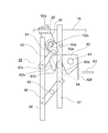
- FIG. 3 is an enlarged front view showing a main part of the car door device when the first and second car doors 2 and 3 in FIG. 1 are fully closed.
- the first car door 2 is provided with a lever shaft 51 and a lever 52.
- the lever shaft 51 is fixed to the first car door 2 parallel to the depth direction of the car and horizontally.
- the lever 52 can rotate around the lever shaft 51. Moreover, the lever 52 has the transmission body connection part 52a.
- the transmitter connection portion 52 a is located at the upper end portion of the lever 52.
- the transmission body connection part 52 a is connected to the transmission body 18 via the gripping member 20. Further, the transmitter connection portion 52 a is rotatable with respect to the gripping member 20 about an axis parallel to the lever shaft 51.
- lever 52 causes the landing door roller 45 to be sandwiched by the vane mechanism 19 when the first car door 2 is opened and closed. Further, the lever 52 releases the pinching of the landing door roller 45 by the vane mechanism 19 when the first car door 2 is fully closed.
- the lever 52 is provided with a lever connecting body 54.
- the lever coupling body 54 is provided on the lever 52 on the opposite side of the lever shaft 51 from the transmission body connecting portion 52a.
- the lever connector 54 is provided at the lower end of the lever shaft 51.
- a roller that can rotate around an axis parallel to the lever shaft 51 is used.
- the distance from the lever shaft 51 to the transmission body connecting portion 52a is larger than the distance from the lever shaft 51 to the lever coupling body 54.
- the vane mechanism 19 includes an upper vane connecting member 53, a connecting member shaft 55, a lower vane connecting member 56, a first vane 57, and a second vane 58.
- the first and second vanes 57 and 58 are arranged in parallel and perpendicular to each other, and sandwich the landing door roller 45 when the first and second car doors 2 are opened and closed.
- the upper vane connecting member 53 is rotatably connected to the first and second vanes 57 and 58.
- the upper vane connecting member 53 is provided on the first car door 2 so as to be rotatable about the lever shaft 51.
- the upper vane connecting member 53 is provided with a slide hole 53a.
- the lever 52 is provided with a protrusion 52b.
- the protrusion 52b has an axial direction parallel to the lever shaft 51 and is inserted into the slide hole 53a. Thereby, the relative rotation of the upper vane connecting member 53 with respect to the lever 52 is restricted.
- the protrusion 52b is slidable within the set range within the slide hole 53a. In other words, a certain margin is provided between the lever 52 and the upper vane connecting member 53.
- the connecting member shaft 55 is fixed to the first car door 2 just below the lever shaft 51. Further, the connecting member shaft 55 is parallel to the lever shaft 51.
- the lower vane connecting member 56 is rotatably connected to the first and second vanes 57 and 58. The lower vane connecting member 56 is provided on the first car door 2 so as to be rotatable about the connecting member shaft 55.
- the upper vane connecting member 53 and the lower vane connecting member 56 function as parallel links that connect the first vane 57 and the second vane 58. Further, the upper vane connecting member 53 interlocks the first and second vanes 57 and 58 with the lever 52.
- FIG. 4 is a front view showing the vane mechanism 19 of FIG.
- FIG. 5 is a front view showing the lever 52 and the gripping member 20 of FIG.
- the first car door 2 is provided with a hook shaft 61 and a hook body 62.
- the hook shaft 61 is fixed to the first car door 2 on the side opposite to the door pocket with respect to the lever shaft 51.
- the hook shaft 61 is parallel to the lever shaft 51.
- the hook body 62 can rotate around the hook shaft 61.
- the hook body 62 transmits the movement of the lever 52 to the first car door 2.
- FIG. 6 is a front view showing the hook body 62 of FIG.
- the hook body 62 has a recess 62a, a claw portion 62b, a hook outer surface 62c, a first inner surface 62d, a second inner surface 62e, and a stopper portion 62f.
- the recess 62a is open downward on the door pocket side of the hook shaft 61.
- the lever coupling body 54 is inserted into the recess 62a.
- the hook body 62 transmits the driving force of the door motor 15 to the first car door 2 as a force in the opening / closing direction.
- claw part 62b is adjacent to the opposite side to the hook shaft 61 of the recessed part 62a.
- the hook outer surface 62c is a surface on the opposite side to the recess 62a of the claw portion 62b, that is, a surface on the door pocket side.
- the first inner surface 62d is the surface of the claw portion 62b opposite to the hook outer surface 62c, that is, the surface from the tip of the claw portion 62b to the bottom of the recess 62a.
- the second inner surface 62e is a surface facing the first inner surface 62d of the recess 62a.
- a release member 63 is fixed to the car door girder 13. When the first and second car doors 2 and 3 are fully closed, the stopper portion 62 f faces the release member 63.
- the circulation direction of the transmission body 18 at this time is a direction in which the gripping member 20 moves to the door pocket side.
- the rotation of the upper vane connecting member 53 causes the first vane 57 to move obliquely upward to the left in FIG. Further, the second vane 58 moves obliquely downward to the right in FIG. As a result, as shown in FIG. 7, the distance between the first and second vanes 57 and 58 is narrowed, and the landing door roller 45 is sandwiched between the first and second vanes 57 and 58.
- the lever coupling body 54 passes through the tip of the claw portion 62b while slightly rotating the hook body 62 in the clockwise direction in FIG. To the second inner surface 62e.
- the second landing door 33 also starts to move toward the door pocket side.
- the gripping member 20 moves to the side opposite to the door pocket.
- the force by which the gripping member 20 moves to the side opposite to the door pocket acts to press the lever coupling body 54 against the first inner surface 62d, and the lever 52 and the hook body 62 are stably coupled to each other.
- the door 2 moves to the opposite side of the door pocket.
- the gripping member 20 After the first and second car doors 2 and 3 are fully closed, the gripping member 20 further moves to the side opposite to the door pocket. Then, the lever 52 rotates in the direction opposite to that at the start of the opening operation, that is, in the clockwise direction in FIG. Thereby, the lever coupling body 54 moves to the hook outer surface 62c side.
- the lever coupling body 54 rotates the hook body 62 in the clockwise direction of FIG. 7 when passing through the tip of the claw portion 62b. Thereby, as shown in FIG. 3, the stopper portion 62 f returns to a state of being separated from the release member 63.
- the vane mechanism 19 is operated by the rotation of the lever 52. Further, the lever coupling body 54 is inserted into the recess 62a when the first and second car doors 2 and 3 are opened and closed. As a result, the driving force of the door motor 15 is stably transmitted to the first car door 2 via the lever 52, the lever coupling body 54, and the hook body 62.
- the vane mechanism 19 can be smoothly operated while shifting the operation timing of the first and second car doors 2 and 3 and the operation timing of the vane mechanism 19.
- the first and second car doors 2 and 3 can also be operated smoothly.
- the stopper 62f is separated from the release member 63 by the rotation of the lever 52 in the direction opposite to that at the start of the opening operation. For this reason, when only the vane mechanism 19 operates, the vane mechanism 19 can be operated more smoothly without being affected by the release member 63. Moreover, the space
- the upper vane connecting member 53 is rotatable with the lever 52 around the lever shaft 51. For this reason, the vane mechanism 19 can be operated more smoothly in conjunction with the rotation of the lever 52.
- vane mechanism 19 can be operated more smoothly by the protrusion 52b sliding in the slide hole 53a.
- the transmission body connecting portion 52a is connected to the transmission body 18 via the gripping member 20. And the transmission body connection part 52a is rotatable with respect to the holding member 20. For this reason, the transmission body 18 can be operated smoothly regardless of the position of the vane mechanism 19.
- the distance from the lever shaft 51 to the transmission body connecting portion 52a is larger than the distance from the lever shaft 51 to the lever coupling body 54. For this reason, the load of the door motor 15 when only the vane mechanism 19 operates can be reduced. Accordingly, it is easy to monitor the motor torque to generate a loss due to a device abnormality occurring in the driving force transmission mechanism and the vane mechanism 19 and contact between the first and second vanes 57 and 58 and the landing door roller 45. Can be detected.
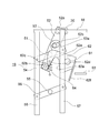
- FIG. 9 is a front view showing an elevator car door device according to Embodiment 2 of the present invention.
- a spring member 64 is provided between the first car door 2 and the hook body 62.
- the spring member 64 applies a mechanical external force to the hook body 62.
- the direction of the mechanical external force is the direction in which the hook outer surface 62c is pressed against the lever connector 54, that is, the counterclockwise direction in FIG.
- the vane mechanism 19 applies a force in a direction to release the pinching of the landing door roller 45 via the hook body 62, the lever coupling body 54, and the lever 52 to the spring member. Receive from 64.
- the spring member 64 for example, a torsion spring provided between the hook shaft 61 and the hook body 62 can be used.
- the spring member 64 may be a coil spring provided between the first car door 2 and the hook body 62.
- Other configurations and operations are the same as those in the first embodiment.
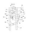
- FIG. 10 is a front view showing an elevator car door device according to Embodiment 3 of the present invention.
- the lever shaft 51 is disposed near the transmitter connection portion 52a. For this reason, the distance from the lever shaft 51 to the lever coupling body 54 is larger than the distance from the lever shaft 51 to the transmission body connecting portion 52a.
- the protrusion 52b is disposed above the lever shaft 51.
- the protrusion 52b is disposed below the lever shaft 51.
- Other configurations and operations are the same as those in the second embodiment.
- the distance from the lever shaft 51 to the lever coupling body 54 is larger than the distance from the lever shaft 51 to the transmission body connecting portion 52a. That is, the distance from the lever shaft 51 to the transmission body connecting portion 52 a is smaller than the distance from the lever shaft 51 to the lever coupling body 54.
- spring member 64 of the third embodiment may be omitted.
- the protrusion 52b is provided on the lever 52 and the slide hole 53a is provided on the upper vane connecting member 53.
- the reverse may be possible.
- the present invention can be applied to a central opening type car door device.
- the number of car doors may be one or three or more.
Landscapes
- Elevator Door Apparatuses (AREA)
Abstract
エレベータのかごドア装置において、レバー連結体は、レバー軸に対して伝達体接続部とは反対側でレバーに設けられている。フック体は、フック軸を中心として回転可能にかごドアに設けられている。また、フック体は、かごドアの開閉動作時にレバー連結体が挿入される凹部と、凹部のフック軸とは反対側に隣接する爪部とを有している。レバー連結体は、かごドアの全閉状態のときに、爪部の凹部とは反対側の面であるフック外面に接しており、かごドアの開放動作開始時に、レバーの回転により凹部内に移動する。
Description
この発明は、乗場ドアをかごドアに連動させるベーン機構を有するエレベータのかごドア装置に関するものである。
従来のエレベータのかごドア装置では、駆動側ベーン及び従動側ベーンは、上部連動リンク機構及び下部連動リンク機構を介してベース板に支持されている。上部連動リンク機構及び下部連動リンク機構は、駆動側ベーンと従動側ベーンとを連動して変位させることにより、駆動側ベーンと従動側ベーンとの間隔を変化させる。
駆動側ベーンの上端部には、結合金具が固定されている。結合金具の上端部は、駆動ベルトに接続されている(例えば、特許文献1参照)。
上記のような従来のかごドア装置では、駆動ベルトにより駆動側ベーンの上端部がドア開閉方向に引っ張られることにより、上部連動リンク機構及び下部連動リンク機構が連動動作する。しかし、駆動側ベーンにはガタがあるため、駆動側ベーン及び従動側ベーンを滑らかに動作させることが難しい。
この発明は、上記のような課題を解決するためになされたものであり、かごドアの動作タイミングと、ベーン機構の動作タイミングとをずらしつつ、ベーン機構を滑らかに動作させることができるエレベータのかごドア装置を得ることを目的とする。
この発明に係るエレベータのかごドア装置は、かごドア、かごドアに設けられており、乗場ドアに設けられた乗場ドアローラを挟み込むことにより、乗場ドアをかごドアに連動させるベーン機構、ドアモータ、ドアモータにより循環動作し、ドアモータの駆動力をかごドアに伝達する環状の伝達体、レバー軸を中心として回転可能にかごドアに設けられており、かつ、伝達体に接続されている伝達体接続部を有しており、かごドアの開閉動作時にベーン機構により乗場ドアローラを挟み込ませるとともに、かごドアが全閉状態のときベーン機構による乗場ドアローラの挟み込みを解除させるレバー、レバー軸に対して伝達体接続部とは反対側でレバーに設けられているレバー連結体、フック軸を中心として回転可能にかごドアに設けられており、かつ、かごドアの開閉動作時にレバー連結体が挿入される凹部と、凹部のフック軸とは反対側に隣接する爪部とを有しており、レバーの移動をかごドアに伝達するフック体、及びかごドア桁に設けられており、かごドアが閉鎖動作して全閉付近となった際に、フック体に接触してフック体を回転させることにより、レバー連結体を凹部の底部から離れさせる解除部材を備え、レバー連結体は、かごドアの全閉状態のときに、爪部の凹部とは反対側の面であるフック外面に接しており、かごドアの開放動作開始時に、レバーの回転により凹部内に移動し、かごドアが閉鎖動作して全閉状態となった後に、開放動作開始時とは反対方向へのレバーの回転により、フック外面側へ移動する。
この発明のエレベータのかごドア装置では、レバーの回転によりベーン機構を動作させる。また、かごドアの開閉動作時にレバー連結体がフック体の凹部に挿入される。これにより、かごドアの動作タイミングと、ベーン機構の動作タイミングとをずらしつつ、ベーン機構を滑らかに動作させることができる。
以下、この発明を実施するための形態について、図面を参照して説明する。
実施の形態1.
図1は、この発明の実施の形態1によるエレベータのかごドア装置を示す正面図であり、かごドア装置を乗場側から見た図である。
実施の形態1.
図1は、この発明の実施の形態1によるエレベータのかごドア装置を示す正面図であり、かごドア装置を乗場側から見た図である。
図において、かご出入口1は、第1のかごドア2及び第2のかごドア3により開閉される。第1のかごドア2は、第1のかごドアパネル4と、第1のかごドアハンガ5とを有している。第1のかごドアハンガ5は、第1のかごドアパネル4の上部に固定されている。
第1のかごドアハンガ5には、一対の第1のかごドアローラ6と、一対の第1のかごドアアップスラストローラ7とが設けられている。一対の第1のかごドアアップスラストローラ7は、一対の第1のかごドアローラ6の下方に配置されている。
第2のかごドア3は、第2のかごドアパネル8と、第2のかごドアハンガ9とを有している。第2のかごドアハンガ9は、第2のかごドアパネル8の上部に固定されている。
第2のかごドアハンガ9には、一対の第2のかごドアローラ10と、一対の第2のかごドアアップスラストローラ11とが設けられている。一対の第2のかごドアアップスラストローラ11は、一対の第2のかごドアローラ10の下方に配置されている。
かごドア桁13は、かご出入口1の上方で、かごに固定されている。かごドア桁13には、かごドアレール14が設けられている。第1及び第2のかごドア2,3は、かごドアレール14から吊り下げられている。
第1及び第2のかごドア2,3の開閉動作時には、第1及び第2のかごドアローラ6,10は、かごドアレール14上を転がりながら移動する。第1及び第2のかごドアアップスラストローラ7,11は、第1及び第2のかごドアローラ6,10のかごドアレール14からの脱落を防止する。
かごドア桁13には、ドアモータ15が固定されている。ドアモータ15は、第1及び第2のかごドア2,3に開閉動作をさせる駆動力を発生する。また、ドアモータ15は、かご出入口1の幅方向のかごドア桁13の一端部に配置されている。また、ドアモータ15は、かごドアレール14の上方に配置されている。ドアモータ15の回転軸は、かごの奥行き方向に平行、かつ水平である。
ドアモータ15の回転軸には、モータプーリ16が固定されている。かご出入口1の幅方向のかごドア桁13の他端部には、連動プーリ17が設けられている。連動プーリ17は、かごドアレール14の上方に配置されている。連動プーリ17の回転軸は、ドアモータ15の回転軸に平行である。
モータプーリ16と連動プーリ17との間には、環状の伝達体18が巻かれている。伝達体18としては、例えば伝達ベルトが用いられている。伝達体18の上側部分及び下側部分は、かご出入口1の幅方向に平行に張られている。
第1のかごドア2には、ベーン機構19が設けられている。伝達体18には、把持部材20が設けられている。把持部材20は、伝達体18の下側部分を把持している。伝達体18の動きは、把持部材20を介して第1のかごドア2に伝達される。伝達体18は、ドアモータ15により循環動作し、ドアモータ15の駆動力を第1のかごドア2に伝達する。伝達体18からベーン機構19及び第1のかごドア2への力の伝達の詳細は、後述する。
第1のかごドア2の開閉動作は、かごドア連動機構21を介して第2のかごドア3に伝達される。ドアモータ15は、制御装置22によって制御されている。制御装置22は、マイクロコンピュータを有している。
実施の形態1のかごドア装置は、片開き式である。即ち、第1及び第2のかごドア2,3は、開閉動作時に同方向へ移動する。
高速ドアである第1のかごドア2は、かご出入口1の全閉時に、戸袋から遠い側に配置されている。低速ドアである第2のかごドア3は、かご出入口1の全閉時に、戸袋に近い側に配置されている。戸袋は、図1の第2のかごドア3の左側である。第1のかごドア2は、開閉動作時に、第2のかごドア3よりも高速で移動する。
図2は、実施の形態1の乗場ドア装置を示す正面図であり、乗場ドア装置を昇降路側から見た図である。
乗場出入口31は、第1の乗場ドア32及び第2の乗場ドア33により開閉される。第1の乗場ドア32は、第1の乗場ドアパネル34と、第1の乗場ドアハンガ35とを有している。第1の乗場ドアハンガ35は、第1の乗場ドアパネル34の上部に固定されている。
第1の乗場ドアハンガ35には、一対の第1の乗場ドアローラ36と、一対の第1の乗場ドアアップスラストローラ37とが設けられている。一対の第1の乗場ドアアップスラストローラ37は、一対の第1の乗場ドアローラ36の下方に配置されている。
第2の乗場ドア33は、第2の乗場ドアパネル38と、第2の乗場ドアハンガ39とを有している。第2の乗場ドアハンガ39は、第2の乗場ドアパネル38の上部に固定されている。
第2の乗場ドアハンガ39には、一対の第2の乗場ドアローラ40と、一対の第2の乗場ドアアップスラストローラ41とが設けられている。一対の第2の乗場ドアアップスラストローラ41は、一対の第2の乗場ドアローラ40の下方に配置されている。
乗場ドア桁43は、乗場出入口31の上方に配置されている。乗場ドア桁43には、乗場ドアレール44が設けられている。第1及び第2の乗場ドア32,33は、乗場ドアレール44から吊り下げられている。
第1及び第2の乗場ドア32,33の開閉動作時には、第1及び第2の乗場ドアローラ36,40は、乗場ドアレール44上を転がりながら移動する。第1及び第2の乗場ドアアップスラストローラ37,41は、第1及び第2の乗場ドアローラ36,40の乗場ドアレール44からの脱落を防止する。
第2の乗場ドア33には、乗場ドアローラ45が設けられている。乗場ドアローラ45には、固定側インターロックローラと可動側インターロックローラとが含まれている。
乗場ドアローラ45は、かごが着床し第1のかごドア2が開放動作する際、ベーン機構19により挟み込まれる。これにより、可動側インターロックローラが回転し、錠装置(図示せず)が解錠される。また、ベーン機構19は、乗場ドアローラ45を挟み込むことにより、第2の乗場ドア33を第1のかごドア2の開閉動作に連動させる。
乗場ドア桁43には、乗場ドア連動機構46が設けられている。第2の乗場ドア33の開閉動作は、乗場ドア連動機構46を介して第1の乗場ドア32に伝達される。
図3は、図1の第1及び第2のかごドア2,3が全閉状態のときのかごドア装置の要部を拡大して示す正面図である。第1のかごドア2には、レバー軸51及びレバー52が設けられている。レバー軸51は、かごの奥行き方向に平行、かつ水平に第1のかごドア2に固定されている。
レバー52は、レバー軸51を中心として回転可能である。また、レバー52は、伝達体接続部52aを有している。伝達体接続部52aは、レバー52の上端部に位置している。伝達体接続部52aは、把持部材20を介して伝達体18に接続されている。また、伝達体接続部52aは、レバー軸51に平行な軸を中心として、把持部材20に対して回転可能である。
また、レバー52は、第1のかごドア2の開閉動作時にベーン機構19により乗場ドアローラ45を挟み込ませる。また、レバー52は、第1のかごドア2が全閉状態のとき、ベーン機構19による乗場ドアローラ45の挟み込みを解除させる。
レバー52には、レバー連結体54が設けられている。レバー連結体54は、レバー軸51に対して伝達体接続部52aとは反対側でレバー52に設けられている。また、レバー連結体54は、レバー軸51の下端部に設けられている。レバー連結体54としては、例えば、レバー軸51に平行な軸を中心として回転可能なローラが用いられている。
レバー軸51から伝達体接続部52aまでの距離は、レバー軸51からレバー連結体54までの距離よりも大きい。
ベーン機構19は、上部ベーン連結部材53、連結部材軸55、下部ベーン連結部材56、第1のベーン57、及び第2のベーン58を有している。第1及び第2のベーン57,58は、互いに平行、かつ鉛直に配置されており、第1及び第2のかごドア2の開閉動作時に乗場ドアローラ45を挟み込む。
上部ベーン連結部材53は、第1及び第2のベーン57,58に回転可能に連結されている。また、上部ベーン連結部材53は、レバー軸51を中心として回転可能に第1のかごドア2に設けられている。
上部ベーン連結部材53には、スライド穴53aが設けられている。レバー52には、突起52bが設けられている。突起52bは、その軸方向がレバー軸51に平行であり、スライド穴53aに挿入されている。これにより、レバー52に対する上部ベーン連結部材53の相対的な回転が規制されている。
また、突起52bは、スライド穴53a内を設定範囲内でスライド可能になっている。即ち、レバー52と上部ベーン連結部材53との間には、ある程度の余裕が設けられている。
連結部材軸55は、レバー軸51の真下で、第1のかごドア2に固定されている。また、連結部材軸55は、レバー軸51に平行である。下部ベーン連結部材56は、第1及び第2のベーン57,58に回転可能に連結されている。また、下部ベーン連結部材56は、連結部材軸55を中心として回転可能に第1のかごドア2に設けられている。
上部ベーン連結部材53及び下部ベーン連結部材56は、第1のベーン57と第2のベーン58とを連結する平行リンクとして機能する。また、上部ベーン連結部材53は、第1及び第2のベーン57,58をレバー52に連動させる。
なお、図4は、図3のベーン機構19を示す正面図である。また、図5は、図3のレバー52及び把持部材20を示す正面図である。
第1のかごドア2には、フック軸61及びフック体62が設けられている。フック軸61は、レバー軸51に対して戸袋とは反対側で、第1のかごドア2に固定されている。また、フック軸61は、レバー軸51に平行である。
フック体62は、フック軸61を中心として回転可能である。また、フック体62は、レバー52の移動を第1のかごドア2に伝達する。
図6は、図3のフック体62を示す正面図である。フック体62は、凹部62a、爪部62b、フック外面62c、第1の内面62d、第2の内面62e、及びストッパ部62fを有している。
凹部62aは、フック軸61の戸袋側で、下向きに開口している。第1及び第2のかごドア2,3の開閉動作時には、レバー連結体54が凹部62aに挿入される。これにより、フック体62は、ドアモータ15の駆動力を、開閉方向への力として第1のかごドア2に伝達する。
爪部62bは、凹部62aのフック軸61とは反対側に隣接している。フック外面62cは、爪部62bの凹部62aとは反対側の面、即ち戸袋側の面である。第1の内面62dは、爪部62bのフック外面62cとは反対側の面、即ち、爪部62bの先端から凹部62aの底部までの面である。第2の内面62eは、凹部62aの第1の内面62dに対向する面である。
かごドア桁13には、解除部材63が固定されている。第1及び第2のかごドア2,3が全閉状態のとき、ストッパ部62fは、解除部材63に対向している。
次に、動作について説明する。第1及び第2のかごドア2,3が全閉状態のとき、レバー連結体54は、図3に示すように、フック外面62cに接している。これにより、爪部62bが下がる方向へのフック体62の回転は規制されている。
第1及び第2のかごドア2,3の開放動作の開始時には、伝達体18がドアモータ15により動かされる。このときの伝達体18の循環方向は、把持部材20が戸袋側へ移動する方向である。
これにより、レバー軸51を中心としてレバー52は、図3の反時計方向へ回転する。また、突起52bがスライド穴53aの縁部に当たり、上部ベーン連結部材53も、レバー軸51を中心としてレバー52と同方向へ回転する。
この上部ベーン連結部材53の回転により、第1のベーン57は、図3の左斜め上方へ移動する。また、第2のベーン58は、図3の右斜め下方へ移動する。これにより、図7に示すように、第1及び第2のベーン57,58の間隔が狭くなり、乗場ドアローラ45が第1及び第2のベーン57,58の間に挟み込まれる。
また、図3の反時計方向へのレバー52の回転により、レバー連結体54は、フック体62を図3の時計方向へ僅かに回転させながら、爪部62bの先端を通過し、凹部62a内に移動し、第2の内面62eに当たる。
図7の状態では、第1及び第2のかごドア2,3は、まだ全閉状態のままである。また、ストッパ部62fは、解除部材63に当たっている。
この後、把持部材20がさらに戸袋側へ移動すると、図8に示すように、レバー連結体54が凹部62a内に入り込む。この状態では、把持部材20が戸袋側へ移動する力は、レバー連結体54を第2の内面62eに押し付けるように作用し、レバー52とフック体62とが安定して連結され、第1のかごドア2が戸袋側へ移動を開始する。
このとき、乗場ドアローラ45が第1及び第2のベーン57,58間に挟み込まれているので、第2の乗場ドア33も戸袋側へ移動を開始する。
第1及び第2のかごドア2,3の閉鎖動作の場合、把持部材20は、戸袋とは反対側へ移動する。把持部材20が戸袋とは反対側へ移動する力は、レバー連結体54を第1の内面62dに押し付けるように作用し、レバー52とフック体62とが安定して連結され、第1のかごドア2が戸袋とは反対側へ移動する。
第1及び第2のかごドア2,3が閉鎖動作して全閉付近となった際、即ち全閉状態となる直前には、解除部材63がストッパ部62fに接触して、フック体62を図7の時計方向へ僅かに回転させる。これにより、第1及び第2のかごドア2,3が全閉状態となった直後には、図7に示すように、解除部材63により、レバー連結体54を凹部62aの底部から離されている。
第1及び第2のかごドア2,3が全閉状態となった後、把持部材20は、戸袋とは反対側へさらに移動する。そして、レバー52は、開放動作の開始時とは反対方向、即ち図7の時計方向へ回転する。これにより、レバー連結体54は、フック外面62c側へ移動する。
また、レバー連結体54は、爪部62bの先端を通過する際に、フック体62を図7の時計方向へ回転させる。これにより、図3に示すように、ストッパ部62fは、解除部材63から離れた状態に戻る。
また、図7の時計方向へのレバー52の回転により、上部ベーン連結部材53も同方向へ回転し、図3に示すように、第1及び第2のベーン57,58の間隔が拡げられる。
このようなエレベータのかごドア装置では、レバー52の回転によりベーン機構19を動作させる。また、第1及び第2のかごドア2,3の開閉動作時にレバー連結体54が凹部62aに挿入される。これにより、レバー52、レバー連結体54及びフック体62を介して、ドアモータ15の駆動力が第1のかごドア2に安定して伝達される。
このため、第1及び第2のかごドア2,3の動作タイミングと、ベーン機構19の動作タイミングとをずらしつつ、ベーン機構19を滑らかに動作させることができる。また、第1及び第2のかごドア2,3も滑らかに動作させることができる。
また、ストッパ部62fは、第1のかごドア2が閉鎖動作して全閉状態となった後に、開放動作開始時とは反対方向へのレバー52の回転により、解除部材63から離れる。このため、ベーン機構19のみが動作する際に、解除部材63の影響を受けず、ベーン機構19をより滑らかに動作させることができる。また、第1及び第2のベーン57,58の間隔を拡げ、乗場機器との接触をより確実に抑制することができる。
また、上部ベーン連結部材53は、レバー軸51を中心としてレバー52とともに回転可能になっている。このため、レバー52の回転に連動させて、ベーン機構19をより滑らかに動作させることができる。
また、突起52bがスライド穴53a内をスライドすることにより、ベーン機構19をさらに滑らかに動作させることができる。
また、伝達体接続部52aは、把持部材20を介して伝達体18に接続されている。そして、伝達体接続部52aは、把持部材20に対して回転可能となっている。このため、ベーン機構19の位置によらず、伝達体18を滑らかに動作させることができる。
また、レバー軸51から伝達体接続部52aまでの距離は、レバー軸51からレバー連結体54までの距離よりも大きい。このため、ベーン機構19のみが動作する際のドアモータ15の負荷を小さくすることができる。これにより、駆動力の伝達機構及びベーン機構19に生じた機器異常によるロスの発生、及び第1及び第2のベーン57,58と乗場ドアローラ45との接触を、モータトルクを監視することで容易に検出することができる。
実施の形態2.
次に、図9は、この発明の実施の形態2によるエレベータのかごドア装置を示す正面図である。実施の形態2では、第1のかごドア2とフック体62との間に、ばね部材64が設けられている。ばね部材64は、フック体62に機械的外力を与える。機械的外力の方向は、フック外面62cをレバー連結体54に押し付ける方向、即ち図9の反時計方向である。
次に、図9は、この発明の実施の形態2によるエレベータのかごドア装置を示す正面図である。実施の形態2では、第1のかごドア2とフック体62との間に、ばね部材64が設けられている。ばね部材64は、フック体62に機械的外力を与える。機械的外力の方向は、フック外面62cをレバー連結体54に押し付ける方向、即ち図9の反時計方向である。
ベーン機構19は、フック外面62cにレバー連結体54が接しているとき、フック体62、レバー連結体54及びレバー52を介して、乗場ドアローラ45の挟み込みを解除する方向への力を、ばね部材64から受ける。
ばね部材64としては、例えば、フック軸61とフック体62との間に設けた捻りばねを用いることができる。また、ばね部材64は、第1のかごドア2とフック体62との間に設けたコイルばねであってもよい。他の構成及び動作は、実施の形態1と同様である。
このようなエレベータのかごドア装置では、ドアモータ15に給電されず、電気的駆動力が発生できない場合に、ばね部材64からの機械的外力により、第1及び第2のベーン57,58の間隔を拡げておくことができる。従って、保守作業時に、ドアモータ15の電源をカットした場合でも、第1及び第2のベーン57,58の間隔を拡げ、乗場機器との干渉を避けつつかごを昇降させることができる。
実施の形態3.
次に、図10は、この発明の実施の形態3によるエレベータのかごドア装置を示す正面図である。実施の形態3では、実施の形態2に比べて、レバー軸51が伝達体接続部52aの近くに配置されている。このため、レバー軸51からレバー連結体54までの距離は、レバー軸51から伝達体接続部52aまでの距離よりも大きい。
次に、図10は、この発明の実施の形態3によるエレベータのかごドア装置を示す正面図である。実施の形態3では、実施の形態2に比べて、レバー軸51が伝達体接続部52aの近くに配置されている。このため、レバー軸51からレバー連結体54までの距離は、レバー軸51から伝達体接続部52aまでの距離よりも大きい。
また、実施の形態2では、レバー軸51の上方に突起52bが配置されていたが、実施の形態3では、レバー軸51の下方に突起52bが配置されている。他の構成及び動作は、実施の形態2と同様である。
このようなエレベータのかごドア装置では、レバー軸51からレバー連結体54までの距離は、レバー軸51から伝達体接続部52aまでの距離よりも大きい。即ち、レバー軸51から伝達体接続部52aまでの距離は、レバー軸51からレバー連結体54までの距離よりも小さい。
このため、ベーン機構19のみが動作する際のドアモータ15の負荷が大きくなる。これにより、ベーン機構19が動作するときと第1及び第2のかごドア2,3が動作するときとで負荷変動が小さくなる。従って、ソフトウェアの制御設定、例えばドアモータ15の負荷に基づいて調整すべきゲイン設定を変更せずに済み、制御を容易にすることができる。
なお、実施の形態3のばね部材64を省略してもよい。
また、上記の例では、レバー52に突起52bを設け、上部ベーン連結部材53にスライド穴53aを設けたが、逆であってもよい。
また、この発明は、中央開き式のかごドア装置にも適用できる。
また、かごドアの枚数は、1枚又は3枚以上であってもよい。
2 第1のかごドア、3 第2のかごドア、13 かごドア桁、15 ドアモータ、18 伝達体、19 ベーン機構、20 把持部材、32 第1の乗場ドア、33 第2の乗場ドア、45 乗場ドアローラ、51 レバー軸、52 レバー、52a 伝達体接続部、52b 突起、53 上部ベーン連結部材、53a スライド穴、54 レバー連結体、57 第1のベーン、58 第2のベーン、61 フック軸、62 フック体、62a 凹部、62b 爪部、62c フック外面、63 解除部材、64 ばね部材。
Claims (8)
- かごドア、
前記かごドアに設けられており、乗場ドアに設けられた乗場ドアローラを挟み込むことにより、前記乗場ドアを前記かごドアに連動させるベーン機構、
ドアモータ、
前記ドアモータにより循環動作し、前記ドアモータの駆動力を前記かごドアに伝達する環状の伝達体、
レバー軸を中心として回転可能に前記かごドアに設けられており、かつ、前記伝達体に接続されている伝達体接続部を有しており、前記かごドアの開閉動作時に前記ベーン機構により前記乗場ドアローラを挟み込ませるとともに、前記かごドアが全閉状態のとき前記ベーン機構による前記乗場ドアローラの挟み込みを解除させるレバー、
前記レバー軸に対して前記伝達体接続部とは反対側で前記レバーに設けられているレバー連結体、
フック軸を中心として回転可能に前記かごドアに設けられており、かつ、前記かごドアの開閉動作時に前記レバー連結体が挿入される凹部と、前記凹部の前記フック軸とは反対側に隣接する爪部とを有しており、前記レバーの移動を前記かごドアに伝達するフック体、及び
かごドア桁に設けられており、前記かごドアが閉鎖動作して全閉付近となった際に、前記フック体に接触して前記フック体を回転させることにより、前記レバー連結体を前記凹部の底部から離れさせる解除部材
を備え、
前記レバー連結体は、
前記かごドアの全閉状態のときに、前記爪部の前記凹部とは反対側の面であるフック外面に接しており、
前記かごドアの開放動作開始時に、前記レバーの回転により前記凹部内に移動し、
前記かごドアが閉鎖動作して全閉状態となった後に、前記開放動作開始時とは反対方向への前記レバーの回転により、前記フック外面側へ移動するエレベータのかごドア装置。 - 前記フック体は、前記かごドアが閉鎖動作して全閉状態となった後に、前記開放動作開始時とは反対方向への前記レバーの回転により、前記解除部材から離れる請求項1記載のエレベータのかごドア装置。
- 前記ベーン機構は、前記乗場ドアローラを挟み込む第1及び第2のベーンと、前記第1及び第2のベーンに回転可能に連結されているベーン連結部材とを有しており、
前記ベーン連結部材は、前記レバー軸を中心として前記レバーとともに回転可能になっている請求項1又は請求項2に記載のエレベータのかごドア装置。 - 前記レバー及び前記ベーン連結部材のいずれか一方には、前記レバー軸に平行な突起が設けられており、
前記レバー及び前記ベーン連結部材の他方には、前記突起が挿入されているスライド穴が設けられており、
前記突起は、前記スライド穴内をスライド可能になっている請求項3記載のエレベータのかごドア装置。 - 前記フック体に機械的外力を与えるばね部材をさらに備え、
前記ベーン機構は、前記フック外面に前記レバー連結体が接しているとき、前記フック体、前記レバー連結体及び前記レバーを介して、前記乗場ドアローラの挟み込みを解除する方向への力を、前記ばね部材から受ける請求項1から請求項4までのいずれか1項に記載のエレベータのかごドア装置。 - 前記伝達体接続部は、前記伝達体を把持する把持部材を介して前記伝達体に接続されており、
前記伝達体接続部は、前記把持部材に対して回転可能である請求項1から請求項5までのいずれか1項に記載のエレベータのかごドア装置。 - 前記レバー軸から前記伝達体接続部までの距離は、前記レバー軸から前記レバー連結体までの距離よりも大きい請求項1から請求項6までのいずれか1項に記載のエレベータのかごドア装置。
- 前記レバー軸から前記伝達体接続部までの距離は、前記レバー軸から前記レバー連結体までの距離よりも小さい請求項1から請求項6までのいずれか1項に記載のエレベータのかごドア装置。
Priority Applications (3)
| Application Number | Priority Date | Filing Date | Title |
|---|---|---|---|
| CN201880092723.5A CN112020473B (zh) | 2018-05-01 | 2018-05-01 | 电梯的轿厢门装置 |
| JP2020516993A JP6880317B2 (ja) | 2018-05-01 | 2018-05-01 | エレベータのかごドア装置 |
| PCT/JP2018/017444 WO2019211900A1 (ja) | 2018-05-01 | 2018-05-01 | エレベータのかごドア装置 |
Applications Claiming Priority (1)
| Application Number | Priority Date | Filing Date | Title |
|---|---|---|---|
| PCT/JP2018/017444 WO2019211900A1 (ja) | 2018-05-01 | 2018-05-01 | エレベータのかごドア装置 |
Publications (1)
| Publication Number | Publication Date |
|---|---|
| WO2019211900A1 true WO2019211900A1 (ja) | 2019-11-07 |
Family
ID=68386390
Family Applications (1)
| Application Number | Title | Priority Date | Filing Date |
|---|---|---|---|
| PCT/JP2018/017444 Ceased WO2019211900A1 (ja) | 2018-05-01 | 2018-05-01 | エレベータのかごドア装置 |
Country Status (3)
| Country | Link |
|---|---|
| JP (1) | JP6880317B2 (ja) |
| CN (1) | CN112020473B (ja) |
| WO (1) | WO2019211900A1 (ja) |
Cited By (1)
| Publication number | Priority date | Publication date | Assignee | Title |
|---|---|---|---|---|
| JPWO2023195124A1 (ja) * | 2022-04-07 | 2023-10-12 |
Citations (4)
| Publication number | Priority date | Publication date | Assignee | Title |
|---|---|---|---|---|
| JP2005170681A (ja) * | 2003-12-08 | 2005-06-30 | Inventio Ag | エレベータドア駆動装置 |
| US20060225966A1 (en) * | 2003-09-17 | 2006-10-12 | Inventio Ag | Device for Connecting a Car Door with a Shaft Door and for Locking and Unlocking the Doors, a Device for Emergency Unlocking of a Car Door and a Method for Emergency Unlocking of a Car Door |
| WO2009011044A1 (ja) * | 2007-07-18 | 2009-01-22 | Mitsubishi Electric Corporation | エレベータのドア係合装置 |
| WO2011043378A1 (ja) * | 2009-10-09 | 2011-04-14 | 三菱電機株式会社 | エレベータのドア係合装置 |
Family Cites Families (2)
| Publication number | Priority date | Publication date | Assignee | Title |
|---|---|---|---|---|
| CN102015510B (zh) * | 2008-06-16 | 2014-01-01 | 三菱电机株式会社 | 电梯的轿厢门锁定装置 |
| CN106687405B (zh) * | 2014-09-11 | 2019-06-18 | 株式会社日立制作所 | 电梯轿厢门锁装置以及电梯的门装置 |
-
2018
- 2018-05-01 CN CN201880092723.5A patent/CN112020473B/zh active Active
- 2018-05-01 WO PCT/JP2018/017444 patent/WO2019211900A1/ja not_active Ceased
- 2018-05-01 JP JP2020516993A patent/JP6880317B2/ja active Active
Patent Citations (4)
| Publication number | Priority date | Publication date | Assignee | Title |
|---|---|---|---|---|
| US20060225966A1 (en) * | 2003-09-17 | 2006-10-12 | Inventio Ag | Device for Connecting a Car Door with a Shaft Door and for Locking and Unlocking the Doors, a Device for Emergency Unlocking of a Car Door and a Method for Emergency Unlocking of a Car Door |
| JP2005170681A (ja) * | 2003-12-08 | 2005-06-30 | Inventio Ag | エレベータドア駆動装置 |
| WO2009011044A1 (ja) * | 2007-07-18 | 2009-01-22 | Mitsubishi Electric Corporation | エレベータのドア係合装置 |
| WO2011043378A1 (ja) * | 2009-10-09 | 2011-04-14 | 三菱電機株式会社 | エレベータのドア係合装置 |
Cited By (3)
| Publication number | Priority date | Publication date | Assignee | Title |
|---|---|---|---|---|
| JPWO2023195124A1 (ja) * | 2022-04-07 | 2023-10-12 | ||
| WO2023195124A1 (ja) * | 2022-04-07 | 2023-10-12 | 株式会社日立製作所 | エレベーターのドア装置、及び、エレベーター |
| JP7780626B2 (ja) | 2022-04-07 | 2025-12-04 | 株式会社日立製作所 | エレベーターのドア装置、及び、エレベーター |
Also Published As
| Publication number | Publication date |
|---|---|
| JP6880317B2 (ja) | 2021-06-02 |
| CN112020473A (zh) | 2020-12-01 |
| JPWO2019211900A1 (ja) | 2020-12-10 |
| CN112020473B (zh) | 2022-07-05 |
Similar Documents
| Publication | Publication Date | Title |
|---|---|---|
| JP6694608B1 (ja) | ドア用係合装置 | |
| JP6926064B2 (ja) | エレベータかごドアインターロック | |
| JP2011063384A (ja) | エレベータドア係合装置 | |
| WO2015008386A1 (ja) | エレベータのかごドアロック装置 | |
| JP3895383B2 (ja) | 自動エレベータドア開閉装置およびドアカプラ | |
| JPWO2008114344A1 (ja) | エレベータの出入口装置 | |
| JPH07285764A (ja) | エレベーターの連動装置 | |
| JP6440920B1 (ja) | エレベータのかごドア装置 | |
| WO2018138896A1 (ja) | エレベーター装置 | |
| CN1964911A (zh) | 电梯的轿厢门联锁装置 | |
| US5636715A (en) | Elevator door structure and method of adjusting the same | |
| WO2019211900A1 (ja) | エレベータのかごドア装置 | |
| JP5832803B2 (ja) | エレベータのホールドア装置 | |
| KR100863514B1 (ko) | 엘리베이터 도어 개폐 장치 | |
| CN112638813B (zh) | 电梯的轿厢门装置 | |
| JP6862605B2 (ja) | エレベータードアの係合装置およびエレベータードア装置 | |
| US5485896A (en) | Rotary elevator car door coupling | |
| JP2010285240A (ja) | エレベータ用ドア装置 | |
| JP7760068B2 (ja) | エレベーターの乗場ドア装置 | |
| JP4802653B2 (ja) | エレベータの戸係合装置 | |
| JP2009269679A (ja) | エレベータのドア装置 | |
| JPH02270793A (ja) | エレベータドア装置 | |
| JPS5847791A (ja) | エレベ−タの扉開閉装置 | |
| CN116529191A (zh) | 轿厢和电梯 | |
| CN112390118A (zh) | 电梯的门装置 |
Legal Events
| Date | Code | Title | Description |
|---|---|---|---|
| 121 | Ep: the epo has been informed by wipo that ep was designated in this application |
Ref document number: 18917180 Country of ref document: EP Kind code of ref document: A1 |
|
| ENP | Entry into the national phase |
Ref document number: 2020516993 Country of ref document: JP Kind code of ref document: A |
|
| NENP | Non-entry into the national phase |
Ref country code: DE |
|
| 122 | Ep: pct application non-entry in european phase |
Ref document number: 18917180 Country of ref document: EP Kind code of ref document: A1 |