WO2019216023A1 - 内視鏡リプロセッサ - Google Patents
内視鏡リプロセッサ Download PDFInfo
- Publication number
- WO2019216023A1 WO2019216023A1 PCT/JP2019/010659 JP2019010659W WO2019216023A1 WO 2019216023 A1 WO2019216023 A1 WO 2019216023A1 JP 2019010659 W JP2019010659 W JP 2019010659W WO 2019216023 A1 WO2019216023 A1 WO 2019216023A1
- Authority
- WO
- WIPO (PCT)
- Prior art keywords
- point
- guide
- movable
- bottle
- accommodating
- Prior art date
- Legal status (The legal status is an assumption and is not a legal conclusion. Google has not performed a legal analysis and makes no representation as to the accuracy of the status listed.)
- Ceased
Links
Images



Classifications
-
- A—HUMAN NECESSITIES
- A61—MEDICAL OR VETERINARY SCIENCE; HYGIENE
- A61B—DIAGNOSIS; SURGERY; IDENTIFICATION
- A61B1/00—Instruments for performing medical examinations of the interior of cavities or tubes of the body by visual or photographical inspection, e.g. endoscopes; Illuminating arrangements therefor
- A61B1/12—Instruments for performing medical examinations of the interior of cavities or tubes of the body by visual or photographical inspection, e.g. endoscopes; Illuminating arrangements therefor with cooling or rinsing arrangements
- A61B1/121—Instruments for performing medical examinations of the interior of cavities or tubes of the body by visual or photographical inspection, e.g. endoscopes; Illuminating arrangements therefor with cooling or rinsing arrangements provided with means for cleaning post-use
-
- A—HUMAN NECESSITIES
- A61—MEDICAL OR VETERINARY SCIENCE; HYGIENE
- A61B—DIAGNOSIS; SURGERY; IDENTIFICATION
- A61B1/00—Instruments for performing medical examinations of the interior of cavities or tubes of the body by visual or photographical inspection, e.g. endoscopes; Illuminating arrangements therefor
- A61B1/12—Instruments for performing medical examinations of the interior of cavities or tubes of the body by visual or photographical inspection, e.g. endoscopes; Illuminating arrangements therefor with cooling or rinsing arrangements
- A61B1/121—Instruments for performing medical examinations of the interior of cavities or tubes of the body by visual or photographical inspection, e.g. endoscopes; Illuminating arrangements therefor with cooling or rinsing arrangements provided with means for cleaning post-use
- A61B1/123—Instruments for performing medical examinations of the interior of cavities or tubes of the body by visual or photographical inspection, e.g. endoscopes; Illuminating arrangements therefor with cooling or rinsing arrangements provided with means for cleaning post-use using washing machines
-
- B—PERFORMING OPERATIONS; TRANSPORTING
- B08—CLEANING
- B08B—CLEANING IN GENERAL; PREVENTION OF FOULING IN GENERAL
- B08B3/00—Cleaning by methods involving the use or presence of liquid or steam
- B08B3/04—Cleaning involving contact with liquid
- B08B3/08—Cleaning involving contact with liquid the liquid having chemical or dissolving effect
-
- B—PERFORMING OPERATIONS; TRANSPORTING
- B67—OPENING, CLOSING OR CLEANING BOTTLES, JARS OR SIMILAR CONTAINERS; LIQUID HANDLING
- B67D—DISPENSING, DELIVERING OR TRANSFERRING LIQUIDS, NOT OTHERWISE PROVIDED FOR
- B67D7/00—Apparatus or devices for transferring liquids from bulk storage containers or reservoirs into vehicles or into portable containers, e.g. for retail sale purposes
- B67D7/02—Apparatus or devices for transferring liquids from bulk storage containers or reservoirs into vehicles or into portable containers, e.g. for retail sale purposes for transferring liquids other than fuel or lubricants
- B67D7/0288—Container connection means
- B67D7/0294—Combined with valves
-
- B—PERFORMING OPERATIONS; TRANSPORTING
- B67—OPENING, CLOSING OR CLEANING BOTTLES, JARS OR SIMILAR CONTAINERS; LIQUID HANDLING
- B67D—DISPENSING, DELIVERING OR TRANSFERRING LIQUIDS, NOT OTHERWISE PROVIDED FOR
- B67D7/00—Apparatus or devices for transferring liquids from bulk storage containers or reservoirs into vehicles or into portable containers, e.g. for retail sale purposes
- B67D7/06—Details or accessories
- B67D7/78—Arrangements of storage tanks, reservoirs or pipe-lines
Definitions
- the present invention relates to an endoscope reprocessor.
- an endoscope reprocessor that uses a chemical solution supplied by a chemical solution supply mechanism and performs a regeneration process such as cleaning and disinfecting an endoscope.
- Japanese Patent Application Laid-Open No. 2009-148315 has a bottle tray that is slidably disposed along a rail that is inclined downward toward the opening inside the bottle housing.
- An endoscope cleaning apparatus is disclosed in which a bottle is accommodated in a bottle tray pulled out from a section, and a chemical solution bottle is set by pushing the bottle tray obliquely upward.
- an object of the present invention is to provide an endoscope reprocessor that can set a chemical bottle in a chemical supply mechanism with a smaller force and can reduce a user's work load.
- An endoscope reprocessor guides a storage unit that stores a chemical bottle so that a sealing unit is positioned on a top surface, and the storage unit can advance and retreat between a first point and a second point.
- a second guide portion that guides the moving direction of the movable portion so that the height difference of the lowering of the opening portion is smaller than the moving distance of the housing portion.
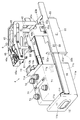
- FIG. 1 is a perspective view showing an example of an endoscope reprocessor 1 according to an embodiment of the present invention.
- the endoscope reprocessor 1 is a device that performs a regeneration process for a contaminated endoscope and parts or accessories of the endoscope.
- the regeneration treatment here is not particularly limited, and is rinsed with water, cleaning to remove dirt such as organic matter, disinfection to invalidate a predetermined microorganism, sterilization to eliminate or kill all microorganisms, or Any of these combinations may be used.
- Accessories are not particularly limited, for example, a suction button that is attached to the endoscope at the time of use and removed from the endoscope at the time of playback processing, an air / water supply button, or a tip cover that covers the tip of the endoscope. Can be mentioned.
- the endoscope reprocessor 1 includes a control unit 2, a pump 3, a chemical solution supply mechanism 4, a chemical solution tank 5, and a connection tube 6.
- the control unit 2 includes a processor and a memory, and is connected to each unit in the endoscope reprocessor 1 such as the pump 3 and the chemical solution supply mechanism 4.
- the control unit 2 controls each unit in the endoscope reprocessor 1 by processing of the processor.
- the chemical solution supply mechanism 4 and the chemical solution tank 5 are connected by a connection tube 6.
- the chemical solution supply mechanism 4 supplies the chemical solution used in the regeneration process to the chemical solution tank 5 through the connection tube 6.
- the chemical solution is, for example, a disinfecting solution containing peracetic acid.
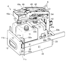
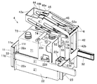
- FIG. 2 is a perspective view showing an example of the chemical solution supply mechanism 4 of the endoscope reprocessor 1 according to the embodiment of the present invention.
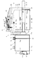
- FIG. 3 is a cross-sectional view of the chemical solution supply mechanism 4 of the endoscope reprocessor 1 according to the embodiment of the present invention.
- the chemical solution supply mechanism 4 includes a storage portion 11, a main body portion 21, a first guide portion 31, a second guide portion 41, a movable portion 51, an opening portion 61, and a chemical solution bottle 71.
- the accommodating part 11 is made of, for example, metal or the like, and accommodates the chemical liquid bottle 71 so that the sealing part 72 of the chemical liquid bottle 71 is positioned on the top surface.
- the accommodating part 11 has a box shape with an upper part opened.
- the accommodating portion 11 includes a bottom plate 11a, a front side plate 11b, left and right side plates 11c, and a rear side plate 11d which are continuously provided so as to rise from the bottom plate 11a.
- the left and right side plates 11c are connected to be adjacent to each of the front side plate 11b and the rear side plate 11d on both the left and right sides of the accommodating portion 11.
- the accommodating part 11 has the extension board 11e extended to the back from the upper side of the front side board 11b, and the taper guide board 11f inclined so that it might approach the bottom plate 11a as it goes back from the extension board 11e.
- the taper guide plate 11f guides the chemical liquid bottle 71 inserted from above to an appropriate storage position.
- a hook 11g is connected to the rear surface of the rear plate 11d.
- the accommodating part 11 has a finger hooking part 12 and a roller receiving part 13.
- the finger hook 12 is made of, for example, rubber or the like, and is configured so that a finger inserted from an opening can be hooked. As shown in FIG. 3, the finger hooking portion 12 is recessed in the opening at the center of the front side plate 11b, is disposed below the extension plate 11e and the taper guide plate 11f, and the back side is bent into a substantially L-shape.
- the roller receiving portion 13 is made of, for example, metal.
- the roller receiving portion 13 is connected to the rear surface of the rear side plate 11d.
- the roller receiving portion 13 has, for example, a cylindrical shape arranged in the vertical direction, and has an engagement groove 13 a that is engaged with the engagement roller 55 of the movable portion 51.
- an engagement groove opening 13b into which the engagement roller 55 can enter is provided at a position corresponding to the first height H1 of the engagement roller 55.
- the engaging groove 13a has a substantially L shape, and extends forward so as to cut out both the left and right side surfaces from the engaging groove opening 13b, and then extends downward.
- the lower end portion of the engagement groove 13a is provided at a position corresponding to the second height H2 of the engagement roller 55.
- the first height H1 is the height of the engagement roller 55 when the movable portion 51 is disposed at the first position P1.
- the second height H2 is the height of the engagement roller 55 when the movable portion 51 is disposed at the second position P2 behind the first position P1.
- the first height H1, the second height H2, the first position P1, and the second position P2 are set in advance.
- the main body 21 is made of, for example, metal.
- the main body portion 21 is provided behind the housing portion 11.
- the main body portion 21 has a substantially U shape, and includes left and right side portions 22 and a rear portion 23 provided continuously between the left and right side portions 22.
- the main body 21 has the accommodating portion 11 set therein.
- an attachment piece 22a for attaching to the inner wall of the endoscope reprocessor 1 is continuously provided outward.
- support pieces 22 b for supporting the accommodated accommodation portion 11 are continuously provided inward.
- a pressing piece 22 c for suppressing the floating of the chemical liquid bottle 71 accommodated in the accommodating portion 11 is continuously provided inward.
- a bottle detection sensor 22d is provided inside the left and right side portions 22
- the bottle detection sensor 22d is constituted by a limit switch, for example.
- the bottle detection sensor 22d is connected to the control unit 2.
- the bottle detection sensor 22d When the chemical liquid bottle 71 accommodated in the accommodating part 11 hits the switch, the bottle detection sensor 22d outputs a control signal indicating that the chemical liquid bottle 71 is set to the control part 2.
- the bottle detection sensor 22d is not limited to the limit switch, and may be configured by other sensors.
- the front surface of the rear part 23 is provided with a lock part 23a.
- the lock part 23a positions and locks the accommodating part 11. More specifically, the lock part 23a stops the rear side plate 11d of the storage part 11 that has entered the main body part 21, and positions the storage part 11 in the advancing and retreating direction. Moreover, the lock part 23a latches the hook 11g of the storage part 11 that has been stopped, and locks the storage part 11 so that it does not fall off.
- the lock unit 23a may include a driving device such as a motor, for example, and the hook 11g may be removed by driving the motor under the control of the control unit 2 to release the lock.
- a bottle remaining amount sensor may be provided inside the rear portion 23.
- the bottle remaining amount sensor is configured by, for example, a capacitance sensor that can detect the water level of the chemical solution in the chemical solution bottle 71.
- the bottle remaining amount sensor is connected to the control unit 2 and outputs a detection result to the control unit 2.
- a second guide mounting plate 23b is provided on the upper side of the rear portion 23 so as to be directed rearward.
- the first guide portion 31 is made of, for example, metal.
- the first guide portion 31 is continuously provided so as to face each of the left and right side portions 22 along the advancing / retreating direction of the housing portion 11.
- the first guide part 31 includes a guide rail 32 and a movable rail 33.
- On the front side of the guide rail 32 an attachment piece 32a for attaching to the inner wall of the endoscope reprocessor 1 is continuously provided outward.
- the movable rail 33 is provided so as to be slidable along the longitudinal direction of the guide rail 32, and is connected to the outer surfaces of the left and right side plates 11c.
- the 1st guide part 31 guides so that the accommodating part 11 can advance / retreat between the 1st point Q1 and the 2nd point Q2.
- the first point Q ⁇ b> 1 is a point where the accommodating part 11 that has left the main body part 21 is arranged.
- the second point Q2 is a point where the accommodating part 11 that has entered the main body part 21 is arranged.
- the first point Q1 and the second point Q2 are set in advance.
- the main body portion 21 is connected to the housing portion 11 by the first guide portion 31, and is connected to the movable portion 51 by the second guide portion 41, and the housing portion 11 is disposed in the main body portion 21 at the second point Q2. Is done.
- the second guide part 41 is made of, for example, metal.
- the second guide portion 41 includes a support plate 42, a guide plate 43, a first guide hole 44, a second guide hole 45, and an urging member connecting portion 46.
- the support plate 42 is erected on the left and right sides above the main body portion 21 to support the guide plate 43.
- a base end mounting plate 42a extends outward in the left-right direction.
- the proximal end attachment plate 42a is attached to the second guide attachment plate 23b.
- Each of the support plates 42 is connected to each other and reinforced by a rear reinforcing plate 42b connected to the rear side.
- the guide plate 43 is arranged in parallel with each other from the upper part of each of the support plates 42 and extends so as to incline upward toward the front.
- Each of the guide plates 43 is connected and reinforced by a front reinforcing plate 43a connected to the front side.
- Each of the guide plates 43 has a first guide hole 44 and a second guide hole 45 that support the movable portion 51.
- the second guide portion 41 has a guide plate 43 that is inclined so as to approach the direction of the main body portion 21 as it goes from the housing portion 11 toward the main body portion 21.
- the first guide hole 44 is provided in front of the second guide hole 45.
- the first guide hole 44 and the second guide hole 45 have an elongated shape and are arranged so as to be parallel to each other along the extending direction of the guide plate 43.
- the urging member connecting portion 46 includes a base 46a provided between the guide plates 43, and a connecting plate 46b that can be adjusted in the front-rear direction by sliding on the base 46a.
- the biasing member 47 has one end connected to the connecting plate 46b and the other end connected to the shaft 53a.
- the urging member 47 urges the movable portion 51 at the second position P2 toward the first position P1.
- the urging member 47 is made of, for example, a spring or an elastomer.
- a tension spring can be used as the spring.
- the movable portion 51 includes a movable plate 52, a first guide roller 53, a second guide roller 54, and an engagement roller 55.
- the movable plate 52 is made of, for example, metal.
- Two movable plates 52 are provided outside the guide plates 43 provided on the left and right sides so as to face each other in the left-right direction.
- Each of the movable plates 52 has a substantially T shape, and has a horizontal plate extending in the front-rear direction and a vertical plate extending downward from the horizontal plate.
- Each of the movable plates 52 is reinforced by a reinforcing plate 52a provided so as to face each other with the guide plate 43 interposed therebetween.
- the positions, directions, and lengths of the first guide hole 44 and the second guide hole 45 in the guide plate 43 and the lengths of the horizontal plate and the vertical plate in the movable plate 52 are related when the movable plate 52 is at the first position P1.
- the combined roller 55 is arranged at the first height H1, and is adjusted and set in advance so that the engaging roller 55 is arranged at the second height H2 when the movable plate 52 is at the second position P2.
- the first guide roller 53, the second guide roller 54, and the engagement roller 55 are made of, for example, resin.
- the first guide roller 53 is rotatably provided so as to be radially outward of the shaft 53 a that connects the front end portions of the horizontal plates and against the inner edge of the first guide hole 44.
- the second guide roller 54 is rotatably provided so as to be radially outward of the shaft 54 a connecting the rear ends of the horizontal plates and against the inner edge of the second guide hole 45.
- the engagement roller 55 is rotatably provided on the outer side in the radial direction of the shaft 55a that connects the lower ends of the vertical plates.
- the accommodating part 11 has the engaging groove 13a which has the engaging groove opening 13b in the position of 1st height H1 by the side of the main-body part 21.
- FIG. The movable portion 51 is disposed at a first height H1 at the first point Q1, and is disposed at a second height H2 lower than the first height H1 at the second point Q2.
- the engaging roller 55 enters the engaging groove 13a from the engaging groove opening 13b when the accommodating portion 11 advances from the first point Q1 to the second point Q2, and is movable from the inner edge of the engaging groove 13a. Power for sliding 51 is transmitted.
- the movable part 51 is interlocked with the progress of the accommodating part 11.
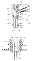
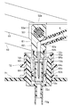
- FIG. 4 is an enlarged cross-sectional view of the opening portion 61 of the chemical solution supply mechanism 4 of the endoscope reprocessor 1 and the sealing portion 72 of the chemical solution bottle 71 according to the embodiment of the present invention.
- the unsealing part 61 is provided at a position corresponding to the sealing part 72 of the chemical liquid bottle 71 in the movable part 51.
- a plurality of opening portions 61 may be provided.
- each of the two chemical liquid bottles 71 includes a sealing portion 72, and two opening portions 61 are provided depending on the position of the sealing portion 72.
- Each of the chemical liquid sucked from each of the two chemical liquid bottles 71 is supplied to the chemical liquid tank 5 and mixed.
- the opening part 61 descends together with the movable part 51 and opens the chemical liquid bottle 71 by perforation.
- the opening part 61 includes a connector 62, a bottle mounting cylinder 63, and a perforating needle 64.
- the connecting tool 62 is made of, for example, metal.
- the coupler 62 is suspended between the guide plates 43 so as to be rotatable on the first guide roller 53 so that the lower end portion thereof is directed downward by gravity.
- a tube mounting cylinder 62 a having a non-slip protrusion is provided on the outer peripheral surface of the connector 62.
- the connection tube 6 is attached to the tube attachment cylinder 62a.
- an O-ring 62b is installed to make the inside of the bottle mounting cylinder 63 airtight.
- the lower end portion of the connector 62 has an opening communicating with the tube mounting cylinder 62a through an internal flow path.
- a spacer for adjusting the position may be provided between the coupling tools 62.
- the bottle mounting cylinder 63 is made of, for example, metal.
- the bottle mounting cylinder 63 is attached to the outer peripheral surface of the lower end portion of the connector 62.
- a mounting port 63 a is provided at the lower end of the bottle mounting cylinder 63.
- On the outer periphery of the lower end portion of the bottle mounting cylinder 63 there is provided a mounting cylinder taper surface 63b whose diameter decreases toward the bottom.
- an O-ring 63c is installed to make the bottle mounting cylinder 63 airtight.
- the punch needle 64 is made of, for example, metal.
- the piercing needle 64 is provided inside the bottle mounting cylinder 63.
- the piercing needle 64 has an internal channel that communicates a lateral hole 64c provided in the outer peripheral surface of the needle tip portion 64b and an opening provided in the needle base portion 64a.
- the needle base portion 64a of the piercing needle 64 is fitted into the opening of the connector 62 so that the needle tip portion 64b faces the attachment port 63a. When fitted into the opening of the connector 62, the internal flow paths of the connector 62 and the puncture needle communicate with each other.
- the unsealing part 61 is disposed at a position higher than the sealing part 72 of the chemical liquid bottle 71 accommodated in the accommodating part 11 at the first point Q1, and descends while sliding as the movable part 51 advances. And it has the shape which was provided in the movable part 51 so that the chemical
- the chemical solution bottle 71 is made of, for example, metal or resin.
- the chemical bottle 71 has a rectangular box shape so that the chemical liquid is stored therein and is accommodated in the accommodating portion 11.
- the chemical liquid bottle 71 includes a sealing portion 72, an air inlet 73, and a fixture 74.
- the sealing part 72 includes a mouth part 72a, an outer cylinder 72b, a sealing part 72 tapered surface 72c, a bottom wall 72d, an inner cylinder 72e, a seal 72f, and a suction tube 72g.
- the mouth portion 72 a is provided so as to protrude from the top surface of the chemical liquid bottle 71. That is, the chemical solution bottle 71 has a sealing portion 72 on the top surface.
- the sealing part 72 is arranged at a position where the opening part 61 is mounted when the chemical liquid bottle 71 is located at the second point Q2.
- the outer cylinder 72b is connected to the inner peripheral surface of the mouth portion 72a.
- the inner edge of the upper end portion of the outer cylinder 72b is provided with a sealing taper surface 72c that decreases in diameter as it goes downward and guides the mounting port 63a.
- the bottom wall 72d is extended inward from the lower end of the outer cylinder 72b.
- the inner cylinder 72e is connected to the inside of the bottom wall 72d so as to be coaxial with the outer cylinder 72b.
- the upper end portion and the lower end portion of the inner cylinder 72e communicate with each other through an internal flow path.
- the seal 72f is made of, for example, a silicon film and seals the upper end portion of the inner cylinder 72e.
- a non-slip protrusion is provided on the outer periphery of the lower end portion of the inner cylinder 72e, and a suction tube 72g is attached.
- the seal 72f is opened.
- the inlet 73 does not leak the chemical in the chemical bottle 71, but is configured by, for example, a waterproof and moisture permeable sheet so as to suck in air when the chemical is sucked from the sealing portion 72.
- the fixing tool 74 fixes each of the chemical liquid bottles 71 when there are a plurality of chemical liquid bottles 71. More specifically, the fixture 74 has an elongated band shape in which locking holes are arranged at both ends, and the locking hole at one end is hung on the locking protrusion of one chemical liquid bottle 71, and the other The locking holes at the ends of the liquid chemical bottles 71 are hooked on the locking protrusions of the other chemical liquid bottle 71 to fix the chemical liquid bottles 71 to each other. The user can hold the fixing device 74 to which the chemical solution bottle 71 is fixed and lift the chemical solution bottle 71.
- FIGS. 5 to 8 are views showing a state in which the storage unit 11 is set in the main body 21 in the chemical solution supply mechanism 4 of the endoscope reprocessor 1 according to the embodiment of the present invention.
- FIG. 5 is a front perspective view
- FIG. 6 is a rear perspective view
- FIG. 7 is a cross-sectional view
- FIG. 8 is an enlarged cross-sectional view showing a state where the opening portion 61 is attached to the sealing portion 72 of the chemical liquid bottle 71. It is.
- the accommodating portion 11 is disposed at the first point Q1, and the movable portion 51 is disposed at the first position P1.
- the engagement roller 55 is arranged at the first height H1 by the arrangement of the first position P1 of the movable portion 51.
- the user stores the chemical bottle 71 in the storage unit 11.
- the accommodating portion 11 advances toward the main body portion 21 along the first guide portion 31.
- the engagement roller 55 enters the engagement groove 13a from the engagement groove opening 13b.
- the engagement roller 55 hits the front edge 13c of the engagement groove 13a, the power is transmitted from the front edge 13c, and the movable portion 51 moves against the second guide portion 41 against the urging force of the urging member 47. Slide diagonally downward.
- the opening part 61 also descends toward the chemical solution bottle 71.
- the bottle mounting cylinder 63 is inserted into the sealing part 72 so that the cylinder wall enters between the outer cylinder 72b and the inner cylinder 72e.
- the punch needle 64 pierces the seal 72f and punches.
- the seal 72f is pierced, the chemical bottle 71 and the connection tube 6 communicate with each other.
- the movable portion 51 when the accommodating portion 11 is set on the main body portion 21, the movable portion 51 is disposed at the second position P2, and the engaging roller 55 is disposed at the second height H2. .
- the movable portion 51 is biased in the direction of the first position P1 by the biasing member 47.
- the storage portion 11 is stopped by the lock portion 23a, the storage portion 11 is positioned at the second point Q2.
- the lock part 23a locks the hook 11g of the storage part 11 so that the storage part 11 does not fall off.
- the control unit 2 outputs a control signal to the lock unit 23a, and unlocks the storage unit 11.
- the user hangs his / her finger on the finger rest 12 and pulls the housing 11 forward.
- the accommodating part 11 retreats from the main body part 21 along the first guide part 31.
- the engagement roller 55 hits the rear edge 13d of the engagement groove 13a, the engagement roller 55 receives power from the rear edge 13d.
- the movable portion 51 since the movable portion 51 receives the urging force of the urging member 47, the movable portion 51 slides obliquely upward along the first guide portion 31.
- the opening portion 61 When the movable portion 51 slides obliquely upward, the opening portion 61 also rises. At this time, the lifting of the chemical bottle 71 is restricted by the pressing piece 22c, and therefore the opening portion 61 is removed from the sealing portion 72.
- the movable portion 51 is disposed at the first position P1, and the engaging roller 55 is disposed at the first height H1.
- FIG. 9 is an explanatory diagram for explaining the pressing force of the user and the opening force of the opening portion 61 in the chemical solution supply mechanism 4 of the endoscope reprocessor 1 according to the embodiment of the present invention.
- the force with which the user pushes the accommodating part 11 is transmitted to the movable part 51, and the opening part 61 is lowered by the movable part 51.
- the horizontal distance component D ⁇ b> 1 included in the movement path of the opening portion 61 is set to be longer than the vertical distance component D ⁇ b> 2.
- the unsealing force for unsealing the unsealed portion 61 is increased by the amount that the vertical distance component D2 is shorter than the horizontal distance component D1.
- the second guide portion 41 guides the moving direction of the movable portion 51 so that the height difference of the lowering of the opening portion 61 becomes smaller than the moving distance of the accommodating portion 11.
- the accommodating portion 11 that accommodates the chemical solution bottle 71 can be set in the main body portion 21 with a smaller force.
- the endoscope reprocessor 1 can set the chemical solution bottle 71 in the chemical solution supply mechanism 4 with a smaller force, and can reduce the work burden on the user.
- the chemical solution may be a disinfectant solution other than peracetic acid, or a detergent, a cleaning solution, alcohol, or the like.
- the rod-shaped member which does not rotate may be sufficient.
- the chemical solution supply mechanism 4 is connected to the chemical solution tank 5 via the connection tube 6, but is not limited thereto.
- the connection tube 6 may be connected to the cleaning tank of the endoscope reprocessor 1.
- the housing portion 11 has the engaging groove 13a and the movable portion 51 has the engaging roller 55, but the reverse may be possible. Also in this case, when the accommodating portion 11 advances from the first point to the second point, the engagement roller enters the engagement groove from the opening of the engagement groove and has a power for sliding the movable portion 51 from the inner edge of the engagement groove. Communicated.
Landscapes
- Health & Medical Sciences (AREA)
- Life Sciences & Earth Sciences (AREA)
- Engineering & Computer Science (AREA)
- Surgery (AREA)
- Mechanical Engineering (AREA)
- Biomedical Technology (AREA)
- Animal Behavior & Ethology (AREA)
- Radiology & Medical Imaging (AREA)
- Optics & Photonics (AREA)
- Nuclear Medicine, Radiotherapy & Molecular Imaging (AREA)
- Physics & Mathematics (AREA)
- Heart & Thoracic Surgery (AREA)
- Medical Informatics (AREA)
- Molecular Biology (AREA)
- Pathology (AREA)
- General Health & Medical Sciences (AREA)
- Public Health (AREA)
- Veterinary Medicine (AREA)
- Biophysics (AREA)
- Chemical & Material Sciences (AREA)
- Chemical Kinetics & Catalysis (AREA)
- General Chemical & Material Sciences (AREA)
- Endoscopes (AREA)
Abstract
Description
図1は、本発明の実施形態に係わる、内視鏡リプロセッサ1の一例を示す斜視図である。
続いて、内視鏡リプロセッサ1の薬液供給機構4の動作について、説明をする。
Claims (8)
- 天面に封止部が位置するよう薬液ボトルを収容する収容部と、
前記収容部が第1地点および第2地点間で進退できるようガイドする第1ガイド部と、
前記収容部の進行に連動する可動部と、
前記可動部に設けられ、前記第1地点において前記収容部に収容された前記薬液ボトルの前記封止部よりも高い位置に配置され、前記可動部の進行に伴いスライドしながら下降して、前記薬液ボトルが前記第2地点に到達するのと連動して前記封止部に突き刺さるよう、所定長さ前記天面へ向けて突出した形状を有する開封部と、
前記収容部の移動距離よりも、前記開封部の下降の高低差の方が小さくなるよう前記可動部の進行方向をガイドする第2ガイド部と、
を含むことを特徴とする内視鏡リプロセッサ。 - 前記天面に前記封止部を有する前記薬液ボトルを含み、
前記封止部は、前記薬液ボトルが前記第2地点に位置するときに、前記開封部が装着される位置に配置されている、
ことを特徴とする請求項1に記載の内視鏡リプロセッサ。 - 本体部を有し、
前記本体部は、前記第1ガイド部によって前記収容部と連結され、前記第2ガイド部によって前記可動部と連結され、
前記収容部は、前記第2地点において、前記本体部内に配置される、
ことを特徴とする請求項1に記載の内視鏡リプロセッサ。 - 前記収容部は、本体部側の第1高さの位置に係合溝開口を有する係合溝を有し、
前記可動部は、前記第1地点において前記第1高さの位置に配置され、前記第2地点において前記第1高さよりも低い第2高さの位置に配置される、係合ローラを有し、
前記係合ローラは、前記収容部が前記第1地点から前記第2地点へ進行すると、前記係合溝開口から前記係合溝に進入し、前記係合溝の内縁から前記可動部をスライドさせる動力が伝達される、
ことを特徴とする請求項1に記載の内視鏡リプロセッサ。 - 前記第2ガイド部は、前記収容部から前記本体部の方向へ向かうにつれて前記本体部の方向に近づくように傾斜したガイド板を有することを特徴とする請求項3に記載の内視鏡リプロセッサ。
- 前記ガイド板は、互いに平行状に配置されることを特徴とする請求項5に記載の内視鏡リプロセッサ。
- 前記ガイド板の各々は、前記可動部を支持する2つのガイド孔を有し、
前記2つのガイド孔は、前記ガイド板の延在方向に沿って互いに平行になるように配置される、
ことを特徴とする請求項6に記載の内視鏡リプロセッサ。 - 前記収容部は、第1高さの位置に係合ローラを有し、
前記可動部は、前記第1地点において前記第1高さの位置に配置され、前記第2地点において前記第1高さよりも低い第2高さの位置に配置され、前記収容部側に開口した係合溝開口を有する、係合溝を有し、
前記係合ローラは、前記収容部が前記第1地点から前記第2地点へ進行すると、前記係合溝開口から前記係合溝に進入し、前記係合溝の内縁から前記可動部をスライドさせる動力が伝達される、
ことを特徴とする請求項1に記載の内視鏡リプロセッサ。
Priority Applications (4)
| Application Number | Priority Date | Filing Date | Title |
|---|---|---|---|
| CN201980045274.3A CN112384124B (zh) | 2018-05-07 | 2019-03-14 | 内窥镜再生处理器具 |
| JP2020518169A JP6945068B2 (ja) | 2018-05-07 | 2019-03-14 | 内視鏡リプロセッサ |
| EP19799095.5A EP3797676B1 (en) | 2018-05-07 | 2019-03-14 | Endoscope reprocessor |
| US17/088,124 US11253143B2 (en) | 2018-05-07 | 2020-11-03 | Endoscope reprocessor |
Applications Claiming Priority (2)
| Application Number | Priority Date | Filing Date | Title |
|---|---|---|---|
| JP2018-089353 | 2018-05-07 | ||
| JP2018089353 | 2018-05-07 |
Related Child Applications (1)
| Application Number | Title | Priority Date | Filing Date |
|---|---|---|---|
| US17/088,124 Continuation US11253143B2 (en) | 2018-05-07 | 2020-11-03 | Endoscope reprocessor |
Publications (1)
| Publication Number | Publication Date |
|---|---|
| WO2019216023A1 true WO2019216023A1 (ja) | 2019-11-14 |
Family
ID=68467361
Family Applications (1)
| Application Number | Title | Priority Date | Filing Date |
|---|---|---|---|
| PCT/JP2019/010659 Ceased WO2019216023A1 (ja) | 2018-05-07 | 2019-03-14 | 内視鏡リプロセッサ |
Country Status (5)
| Country | Link |
|---|---|
| US (1) | US11253143B2 (ja) |
| EP (1) | EP3797676B1 (ja) |
| JP (1) | JP6945068B2 (ja) |
| CN (1) | CN112384124B (ja) |
| WO (1) | WO2019216023A1 (ja) |
Cited By (1)
| Publication number | Priority date | Publication date | Assignee | Title |
|---|---|---|---|---|
| WO2022157947A1 (ja) * | 2021-01-22 | 2022-07-28 | オリンパスメディカルシステムズ株式会社 | 医療機器用リプロセッサ、ボトル |
Families Citing this family (3)
| Publication number | Priority date | Publication date | Assignee | Title |
|---|---|---|---|---|
| WO2019216023A1 (ja) * | 2018-05-07 | 2019-11-14 | オリンパス株式会社 | 内視鏡リプロセッサ |
| WO2024091398A1 (en) * | 2022-10-27 | 2024-05-02 | American Sterilizer Company | Cup deployment system and detachable door for automated endoscope reprocessor |
| JP7749166B1 (ja) * | 2024-07-09 | 2025-10-03 | オリンパスメディカルシステムズ株式会社 | 洗浄消毒装置および薬液ボトル |
Citations (4)
| Publication number | Priority date | Publication date | Assignee | Title |
|---|---|---|---|---|
| JP2009148315A (ja) | 2007-12-18 | 2009-07-09 | Olympus Medical Systems Corp | 内視鏡洗浄消毒装置 |
| WO2015104872A1 (ja) * | 2014-01-08 | 2015-07-16 | オリンパス株式会社 | 内視鏡洗浄消毒装置 |
| WO2016080074A1 (ja) * | 2014-11-17 | 2016-05-26 | オリンパス株式会社 | 内視鏡リプロセッサ |
| JP2018089353A (ja) | 2017-09-27 | 2018-06-14 | 株式会社バンダイ | 模型玩具 |
Family Cites Families (23)
| Publication number | Priority date | Publication date | Assignee | Title |
|---|---|---|---|---|
| US4840621A (en) * | 1988-01-19 | 1989-06-20 | Abbott Laboratories | Piercing pin transfer device |
| JP3762680B2 (ja) * | 2001-10-03 | 2006-04-05 | オリンパス株式会社 | 内視鏡洗滌消毒装置 |
| US6874517B2 (en) * | 2003-05-28 | 2005-04-05 | Steris Inc. | Valve holding fixture for automated reprocessor |
| US7476368B2 (en) * | 2003-08-01 | 2009-01-13 | American Sterilizer Company | Method and device for deactivating items and for maintaining such items in a deactivated state |
| JP3967729B2 (ja) * | 2004-03-22 | 2007-08-29 | オリンパス株式会社 | 内視鏡洗滌消毒装置 |
| WO2005089633A1 (ja) * | 2004-03-22 | 2005-09-29 | Olympus Corporation | 内視鏡洗滌消毒システム、内視鏡洗滌消毒装置及び内視鏡 |
| US7901349B2 (en) * | 2005-11-02 | 2011-03-08 | Minntech Corporation | Endoscope reprocessor connectivity apparatus and method |
| CN1961814A (zh) * | 2005-11-11 | 2007-05-16 | 奥林巴斯医疗株式会社 | 内窥镜洗涤消毒装置 |
| JP4989291B2 (ja) * | 2007-04-26 | 2012-08-01 | オリンパスメディカルシステムズ株式会社 | 内視鏡洗浄消毒装置 |
| JP5086737B2 (ja) * | 2007-08-16 | 2012-11-28 | 富士フイルム株式会社 | 内視鏡洗浄機 |
| EP2025282B1 (en) * | 2007-08-16 | 2011-04-20 | FUJIFILM Corporation | Endoscope reprocessor |
| JP5192936B2 (ja) * | 2008-07-31 | 2013-05-08 | オリンパスメディカルシステムズ株式会社 | 内視鏡洗浄消毒装置 |
| JP5547203B2 (ja) * | 2008-10-13 | 2014-07-09 | エシコン・インコーポレイテッド | 内視鏡再処理システムのための流体コネクタ |
| EP2508121A4 (en) * | 2010-11-24 | 2012-11-14 | Olympus Medical Systems Corp | CHEMICAL BOTTLE FOR ENDOSCOPIC CLEANING AND DISINFECTION DEVICE |
| JP4674272B1 (ja) * | 2010-11-24 | 2011-04-20 | オリンパスメディカルシステムズ株式会社 | 内視鏡洗浄消毒装置 |
| JP2013165803A (ja) * | 2012-02-15 | 2013-08-29 | Johnson & Johnson Kk | 液体投入機構および内視鏡洗浄装置 |
| JP2013165805A (ja) * | 2012-02-15 | 2013-08-29 | Johnson & Johnson Kk | 容器開封機構および内視鏡洗浄装置 |
| JP5829367B1 (ja) * | 2014-05-13 | 2015-12-09 | オリンパス株式会社 | 内視鏡接続具 |
| JP5885894B1 (ja) * | 2014-06-25 | 2016-03-16 | オリンパス株式会社 | 内視鏡リプロセッサ |
| WO2016084450A1 (ja) * | 2014-11-25 | 2016-06-02 | オリンパス株式会社 | 内視鏡接続具及び内視鏡リプロセッサ |
| EP3162278B1 (en) * | 2015-08-24 | 2019-07-24 | Olympus Corporation | Endoscope reprocessor |
| CN107027286B (zh) * | 2015-12-01 | 2019-01-22 | 奥林巴斯株式会社 | 内窥镜清洗消毒机及内窥镜再处理成套设备 |
| WO2019216023A1 (ja) * | 2018-05-07 | 2019-11-14 | オリンパス株式会社 | 内視鏡リプロセッサ |
-
2019
- 2019-03-14 WO PCT/JP2019/010659 patent/WO2019216023A1/ja not_active Ceased
- 2019-03-14 EP EP19799095.5A patent/EP3797676B1/en active Active
- 2019-03-14 CN CN201980045274.3A patent/CN112384124B/zh active Active
- 2019-03-14 JP JP2020518169A patent/JP6945068B2/ja active Active
-
2020
- 2020-11-03 US US17/088,124 patent/US11253143B2/en active Active
Patent Citations (4)
| Publication number | Priority date | Publication date | Assignee | Title |
|---|---|---|---|---|
| JP2009148315A (ja) | 2007-12-18 | 2009-07-09 | Olympus Medical Systems Corp | 内視鏡洗浄消毒装置 |
| WO2015104872A1 (ja) * | 2014-01-08 | 2015-07-16 | オリンパス株式会社 | 内視鏡洗浄消毒装置 |
| WO2016080074A1 (ja) * | 2014-11-17 | 2016-05-26 | オリンパス株式会社 | 内視鏡リプロセッサ |
| JP2018089353A (ja) | 2017-09-27 | 2018-06-14 | 株式会社バンダイ | 模型玩具 |
Non-Patent Citations (1)
| Title |
|---|
| See also references of EP3797676A4 |
Cited By (4)
| Publication number | Priority date | Publication date | Assignee | Title |
|---|---|---|---|---|
| WO2022157947A1 (ja) * | 2021-01-22 | 2022-07-28 | オリンパスメディカルシステムズ株式会社 | 医療機器用リプロセッサ、ボトル |
| JPWO2022157947A1 (ja) * | 2021-01-22 | 2022-07-28 | ||
| JP7460803B2 (ja) | 2021-01-22 | 2024-04-02 | オリンパスメディカルシステムズ株式会社 | 医療機器用リプロセッサ、ボトル |
| EP4265170A4 (en) * | 2021-01-22 | 2024-10-23 | Olympus Medical Systems Corp. | REPROCESSING DEVICE FOR MEDICAL DEVICE AND BOTTLE |
Also Published As
| Publication number | Publication date |
|---|---|
| JPWO2019216023A1 (ja) | 2021-04-22 |
| EP3797676A4 (en) | 2022-01-19 |
| US11253143B2 (en) | 2022-02-22 |
| JP6945068B2 (ja) | 2021-10-06 |
| CN112384124B (zh) | 2024-04-09 |
| US20210127962A1 (en) | 2021-05-06 |
| EP3797676A1 (en) | 2021-03-31 |
| EP3797676B1 (en) | 2023-04-26 |
| CN112384124A (zh) | 2021-02-19 |
Similar Documents
| Publication | Publication Date | Title |
|---|---|---|
| WO2019216023A1 (ja) | 内視鏡リプロセッサ | |
| CN100455254C (zh) | 医疗器械洗涤消毒系统 | |
| US8034193B2 (en) | Endoscope cleaning/disinfecting apparatus | |
| EP2638847B1 (en) | Endoscope cleaning/desinfecting apparatus | |
| US20160249794A1 (en) | Endoscope reprocessor | |
| KR102024089B1 (ko) | 로봇 청소기 | |
| EP1844698A2 (en) | Apparatus for washing and disinfecting endoscope and brush unit for washing ducts of endoscope | |
| JP6001215B2 (ja) | 挿入機器の洗浄具 | |
| EP2457595A1 (en) | Endoscope cleaning/disinfecting apparatus | |
| EP2886038A1 (en) | Endoscope connector | |
| EP3081145B1 (en) | Endoscope connector and endoscope reprocessor | |
| JPWO2016059919A1 (ja) | 挿入機器の洗浄具 | |
| US12140471B2 (en) | Windshield for balance | |
| US10357585B2 (en) | Liquid supplying system | |
| EP2578240A1 (en) | Sterilization apparatus and method | |
| JP5085346B2 (ja) | 内視鏡洗浄消毒装置 | |
| KR20180000086A (ko) | 의료용 기구 멸균기내 멸균제 공급장치 | |
| JP5060930B2 (ja) | 内視鏡洗浄消毒装置 | |
| JP2013103017A (ja) | 内視鏡洗浄消毒装置 | |
| JP5014954B2 (ja) | 内視鏡洗浄消毒装置 | |
| JP5248871B2 (ja) | 内視鏡洗浄消毒システム | |
| JP5132349B2 (ja) | 内視鏡洗浄消毒装置 | |
| JP4549760B2 (ja) | 穿刺用超音波探触子 | |
| US20180364085A1 (en) | Liquid supplying system and method for driving same | |
| WO2019035249A1 (ja) | 内視鏡リプロセッサ |
Legal Events
| Date | Code | Title | Description |
|---|---|---|---|
| 121 | Ep: the epo has been informed by wipo that ep was designated in this application |
Ref document number: 19799095 Country of ref document: EP Kind code of ref document: A1 |
|
| ENP | Entry into the national phase |
Ref document number: 2020518169 Country of ref document: JP Kind code of ref document: A |
|
| NENP | Non-entry into the national phase |
Ref country code: DE |
|
| ENP | Entry into the national phase |
Ref document number: 2019799095 Country of ref document: EP Effective date: 20201202 |
|
| ENP | Entry into the national phase |
Ref document number: 2019799095 Country of ref document: EP Effective date: 20201202 |