WO2019216421A1 - 車両用ドア制御装置 - Google Patents
車両用ドア制御装置 Download PDFInfo
- Publication number
- WO2019216421A1 WO2019216421A1 PCT/JP2019/018786 JP2019018786W WO2019216421A1 WO 2019216421 A1 WO2019216421 A1 WO 2019216421A1 JP 2019018786 W JP2019018786 W JP 2019018786W WO 2019216421 A1 WO2019216421 A1 WO 2019216421A1
- Authority
- WO
- WIPO (PCT)
- Prior art keywords
- door
- control device
- swipe operation
- vehicle
- unit
- Prior art date
- Legal status (The legal status is an assumption and is not a legal conclusion. Google has not performed a legal analysis and makes no representation as to the accuracy of the status listed.)
- Ceased
Links
Images


Classifications
-
- B—PERFORMING OPERATIONS; TRANSPORTING
- B60—VEHICLES IN GENERAL
- B60Q—ARRANGEMENT OF SIGNALLING OR LIGHTING DEVICES, THE MOUNTING OR SUPPORTING THEREOF OR CIRCUITS THEREFOR, FOR VEHICLES IN GENERAL
- B60Q3/00—Arrangement of lighting devices for vehicle interiors; Lighting devices specially adapted for vehicle interiors
- B60Q3/20—Arrangement of lighting devices for vehicle interiors; Lighting devices specially adapted for vehicle interiors for lighting specific fittings of passenger or driving compartments; mounted on specific fittings of passenger or driving compartments
- B60Q3/217—Doors, e.g. door sills; Steps
-
- B—PERFORMING OPERATIONS; TRANSPORTING
- B60—VEHICLES IN GENERAL
- B60J—WINDOWS, WINDSCREENS, NON-FIXED ROOFS, DOORS, OR SIMILAR DEVICES FOR VEHICLES; REMOVABLE EXTERNAL PROTECTIVE COVERINGS SPECIALLY ADAPTED FOR VEHICLES
- B60J5/00—Doors
- B60J5/04—Doors arranged at the vehicle sides
- B60J5/0412—Lower door structure
- B60J5/0413—Inner panel, e.g. characterised by carrying components
-
- B—PERFORMING OPERATIONS; TRANSPORTING
- B60—VEHICLES IN GENERAL
- B60J—WINDOWS, WINDSCREENS, NON-FIXED ROOFS, DOORS, OR SIMILAR DEVICES FOR VEHICLES; REMOVABLE EXTERNAL PROTECTIVE COVERINGS SPECIALLY ADAPTED FOR VEHICLES
- B60J5/00—Doors
- B60J5/04—Doors arranged at the vehicle sides
- B60J5/0468—Fixation or mounting means specific for door components
-
- B—PERFORMING OPERATIONS; TRANSPORTING
- B60—VEHICLES IN GENERAL
- B60R—VEHICLES, VEHICLE FITTINGS, OR VEHICLE PARTS, NOT OTHERWISE PROVIDED FOR
- B60R25/00—Fittings or systems for preventing or indicating unauthorised use or theft of vehicles
- B60R25/01—Fittings or systems for preventing or indicating unauthorised use or theft of vehicles operating on vehicle systems or fittings, e.g. on doors, seats or windscreens
-
- B—PERFORMING OPERATIONS; TRANSPORTING
- B60—VEHICLES IN GENERAL
- B60R—VEHICLES, VEHICLE FITTINGS, OR VEHICLE PARTS, NOT OTHERWISE PROVIDED FOR
- B60R25/00—Fittings or systems for preventing or indicating unauthorised use or theft of vehicles
- B60R25/20—Means to switch the anti-theft system on or off
-
- E—FIXED CONSTRUCTIONS
- E05—LOCKS; KEYS; WINDOW OR DOOR FITTINGS; SAFES
- E05B—LOCKS; ACCESSORIES THEREFOR; HANDCUFFS
- E05B81/00—Power-actuated vehicle locks
- E05B81/54—Electrical circuits
- E05B81/56—Control of actuators
-
- E—FIXED CONSTRUCTIONS
- E05—LOCKS; KEYS; WINDOW OR DOOR FITTINGS; SAFES
- E05B—LOCKS; ACCESSORIES THEREFOR; HANDCUFFS
- E05B81/00—Power-actuated vehicle locks
- E05B81/54—Electrical circuits
- E05B81/64—Monitoring or sensing, e.g. by using switches or sensors
- E05B81/76—Detection of handle operation; Detection of a user approaching a handle; Electrical switching actions performed by door handles
- E05B81/77—Detection of handle operation; Detection of a user approaching a handle; Electrical switching actions performed by door handles comprising sensors detecting the presence of the hand of a user
-
- E—FIXED CONSTRUCTIONS
- E05—LOCKS; KEYS; WINDOW OR DOOR FITTINGS; SAFES
- E05B—LOCKS; ACCESSORIES THEREFOR; HANDCUFFS
- E05B85/00—Details of vehicle locks not provided for in groups E05B77/00 - E05B83/00
- E05B85/10—Handles
- E05B85/12—Inner door handles
-
- H—ELECTRICITY
- H03—ELECTRONIC CIRCUITRY
- H03K—PULSE TECHNIQUE
- H03K17/00—Electronic switching or gating, i.e. not by contact-making and –breaking
- H03K17/94—Electronic switching or gating, i.e. not by contact-making and –breaking characterised by the way in which the control signals are generated
- H03K17/96—Touch switches
- H03K17/962—Capacitive touch switches
- H03K17/9622—Capacitive touch switches using a plurality of detectors, e.g. keyboard
-
- B—PERFORMING OPERATIONS; TRANSPORTING
- B60—VEHICLES IN GENERAL
- B60Q—ARRANGEMENT OF SIGNALLING OR LIGHTING DEVICES, THE MOUNTING OR SUPPORTING THEREOF OR CIRCUITS THEREFOR, FOR VEHICLES IN GENERAL
- B60Q2900/00—Features of lamps not covered by other groups in B60Q
- B60Q2900/40—Several lamps activated in sequence, e.g. sweep effect, progressive activation
-
- B—PERFORMING OPERATIONS; TRANSPORTING
- B60—VEHICLES IN GENERAL
- B60R—VEHICLES, VEHICLE FITTINGS, OR VEHICLE PARTS, NOT OTHERWISE PROVIDED FOR
- B60R16/00—Electric or fluid circuits specially adapted for vehicles and not otherwise provided for; Arrangement of elements of electric or fluid circuits specially adapted for vehicles and not otherwise provided for
- B60R16/02—Electric or fluid circuits specially adapted for vehicles and not otherwise provided for; Arrangement of elements of electric or fluid circuits specially adapted for vehicles and not otherwise provided for electric constitutive elements
- B60R16/023—Electric or fluid circuits specially adapted for vehicles and not otherwise provided for; Arrangement of elements of electric or fluid circuits specially adapted for vehicles and not otherwise provided for electric constitutive elements for transmission of signals between vehicle parts or subsystems
- B60R16/0231—Circuits relating to the driving or the functioning of the vehicle
-
- E—FIXED CONSTRUCTIONS
- E05—LOCKS; KEYS; WINDOW OR DOOR FITTINGS; SAFES
- E05Y—INDEXING SCHEME ASSOCIATED WITH SUBCLASSES E05D AND E05F, RELATING TO CONSTRUCTION ELEMENTS, ELECTRIC CONTROL, POWER SUPPLY, POWER SIGNAL OR TRANSMISSION, USER INTERFACES, MOUNTING OR COUPLING, DETAILS, ACCESSORIES, AUXILIARY OPERATIONS NOT OTHERWISE PROVIDED FOR, APPLICATION THEREOF
- E05Y2400/00—Electronic control; Electrical power; Power supply; Power or signal transmission; User interfaces
- E05Y2400/80—User interfaces
- E05Y2400/85—User input means
- E05Y2400/856—Actuation thereof
- E05Y2400/858—Actuation thereof by body parts, e.g. by feet
- E05Y2400/86—Actuation thereof by body parts, e.g. by feet by hand
-
- E—FIXED CONSTRUCTIONS
- E05—LOCKS; KEYS; WINDOW OR DOOR FITTINGS; SAFES
- E05Y—INDEXING SCHEME ASSOCIATED WITH SUBCLASSES E05D AND E05F, RELATING TO CONSTRUCTION ELEMENTS, ELECTRIC CONTROL, POWER SUPPLY, POWER SIGNAL OR TRANSMISSION, USER INTERFACES, MOUNTING OR COUPLING, DETAILS, ACCESSORIES, AUXILIARY OPERATIONS NOT OTHERWISE PROVIDED FOR, APPLICATION THEREOF
- E05Y2900/00—Application of doors, windows, wings or fittings thereof
- E05Y2900/50—Application of doors, windows, wings or fittings thereof for vehicles
- E05Y2900/53—Type of wing
- E05Y2900/531—Doors
-
- G—PHYSICS
- G06—COMPUTING OR CALCULATING; COUNTING
- G06F—ELECTRIC DIGITAL DATA PROCESSING
- G06F3/00—Input arrangements for transferring data to be processed into a form capable of being handled by the computer; Output arrangements for transferring data from processing unit to output unit, e.g. interface arrangements
- G06F3/01—Input arrangements or combined input and output arrangements for interaction between user and computer
- G06F3/048—Interaction techniques based on graphical user interfaces [GUI]
- G06F3/0487—Interaction techniques based on graphical user interfaces [GUI] using specific features provided by the input device, e.g. functions controlled by the rotation of a mouse with dual sensing arrangements, or of the nature of the input device, e.g. tap gestures based on pressure sensed by a digitiser
- G06F3/0488—Interaction techniques based on graphical user interfaces [GUI] using specific features provided by the input device, e.g. functions controlled by the rotation of a mouse with dual sensing arrangements, or of the nature of the input device, e.g. tap gestures based on pressure sensed by a digitiser using a touch-screen or digitiser, e.g. input of commands through traced gestures
-
- H—ELECTRICITY
- H03—ELECTRONIC CIRCUITRY
- H03K—PULSE TECHNIQUE
- H03K2217/00—Indexing scheme related to electronic switching or gating, i.e. not by contact-making or -breaking covered by H03K17/00
- H03K2217/94—Indexing scheme related to electronic switching or gating, i.e. not by contact-making or -breaking covered by H03K17/00 characterised by the way in which the control signal is generated
- H03K2217/94052—Indexing scheme related to electronic switching or gating, i.e. not by contact-making or -breaking covered by H03K17/00 characterised by the way in which the control signal is generated with evaluation of actuation pattern or sequence, e.g. tapping
-
- H—ELECTRICITY
- H03—ELECTRONIC CIRCUITRY
- H03K—PULSE TECHNIQUE
- H03K2217/00—Indexing scheme related to electronic switching or gating, i.e. not by contact-making or -breaking covered by H03K17/00
- H03K2217/94—Indexing scheme related to electronic switching or gating, i.e. not by contact-making or -breaking covered by H03K17/00 characterised by the way in which the control signal is generated
- H03K2217/96—Touch switches
- H03K2217/96066—Thumbwheel, potentiometer, scrollbar or slider simulation by touch switch
-
- H—ELECTRICITY
- H03—ELECTRONIC CIRCUITRY
- H03K—PULSE TECHNIQUE
- H03K2217/00—Indexing scheme related to electronic switching or gating, i.e. not by contact-making or -breaking covered by H03K17/00
- H03K2217/94—Indexing scheme related to electronic switching or gating, i.e. not by contact-making or -breaking covered by H03K17/00 characterised by the way in which the control signal is generated
- H03K2217/96—Touch switches
- H03K2217/9607—Capacitive touch switches
- H03K2217/960785—Capacitive touch switches with illumination
Definitions
- the present invention relates to a vehicle door control device.
- a door lock device described in Patent Document 1 includes a latch member that holds a door in a closed state, a ball member that locks the latch member, and an unlock instruction that generates a door opening instruction signal by detecting contact with the door grip. And unlocking means for unlocking the latch member by the ball member in response to the door opening instruction signal.
- this door lock device when the user grips the door grip, contact with the door grip is detected and a door opening instruction signal is generated. Accordingly, the latch member is unlocked, and the door can be opened by driving the door in the opening direction. Therefore, since it responds to the operation of the person for opening the door to grasp the door grip, no conscious operation is required.
- the user's operation intention can be appropriately reflected in the vehicle door control device.
- the vehicle door control device includes a swipe operation unit provided on the vehicle interior side of the door, and a swipe operation that is provided at least in the swipe operation unit and moves the human body along the swipe operation unit.
- a detection unit that detects a closed state of the door, a door lock device that maintains a closed state of the door, and a controller that releases the door closed state by the door lock device when a swipe operation is determined based on a detection result of the detection unit.
- the vehicle door control device may be further provided with a handle portion that is provided on the vehicle interior side of the door and becomes a handle when the door is opened and closed.
- the swipe operation part is shaped so as to be continuous with the handle part, and the controller determines the swipe operation to move the swipe operation part toward the handle part when the door is locked by the door lock device. It is preferable to release the closed state.
- the vehicle door control device may further include a handle portion provided on the vehicle interior side of the door and serving as a handle when the door is opened and closed.
- the swipe operation unit may be set so as to span part or all of the shaping of the handle part, or may be set to overlap with part or all of the shaping of the handle part. preferable.
- the vehicle door control device further includes an illumination unit that is provided at least in the swipe operation unit and guides the direction of the swipe operation with illumination.
- the vehicle door control device includes a latch that holds the door closed state by engaging the door lock device with the vehicle body, and the controller releases the latch when the swipe operation is determined. At the same time, it is preferable to continue releasing the latch until the door opening angle reaches a threshold value or more.
- the detection unit is preferably a capacitance sensor that detects a user's contact by a change in capacitance.
- a plurality of capacitance sensors are arranged at intervals from the upstream side to the downstream side in the direction of the swipe operation.
- the controller can accept sensor input only for the most upstream capacitive sensor, and the downstream capacitive sensor can be sequentially switched to accept sensor input according to the detection status of the user's swipe operation. preferable.
- FIG. 1 is a front view showing a side door to which the vehicle door control device according to the present embodiment is applied.
- FIG. 2 is a perspective view showing the side door.
- FIG. 3 is a block diagram illustrating a configuration of the vehicle door control device.
- FIG. 4 is an enlarged front view showing a main part of the side door.
- FIG. 5 is an explanatory diagram showing the configuration of the unlatch unit.
- FIG. 6 is an explanatory diagram showing the configuration of the lock unit.
- FIGS. 7A to 7D are explanatory diagrams for explaining the operation of the lock unit.
- FIG. 8 is a flowchart for explaining the operation of the vehicle door control device according to the present embodiment.
- FIG. 9 is a flowchart for explaining the operation of the vehicle door control device according to the present embodiment.
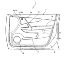
- FIG. 1 is a front view showing the side door 1 to which the vehicle door control device 10 according to the present embodiment is applied.
- FIG. 2 is a perspective view showing the side door 1.
- FIG. 3 is a block diagram showing the configuration of the vehicle door control device 10.
- FIG. 4 is an enlarged front view showing a main part of the side door 1.
- the side door 1 is a front side door that opens and closes a door opening between the front pillar and the center pillar.
- the front end of the side door 1 is connected to the vehicle body via a hinge mechanism (not shown), and is configured to be rotatable about the hinge mechanism.
- the side door 1 is mainly composed of a door main body 2 and a door trim 3.
- the door body 2 includes a door outer panel that forms a door half outside the vehicle compartment and a door inner panel that forms a door half inside the vehicle compartment.
- the door outer panel and the door inner panel are configured in a closed cross section in which peripheral portions are joined to each other and a space is formed therein.
- the door trim 3 is an interior part that decorates the vehicle interior, and is provided on the vehicle interior side of the door body 2 so as to cover the door body 2.
- the main part of the door trim 3 has a surface shape along the vehicle vertical direction and the vehicle front-rear direction.
- a door pocket 3a is provided at a position below the door trim 3 in the vehicle vertical direction, and a speaker grill 3b is provided at a position ahead of the door pocket 3a.
- a door armrest 3c is provided at a center position of the door trim 3 in the vehicle vertical direction.
- a door assist grip (handle portion) 3d which becomes a handle when the side door 1 is opened and closed.
- the door assist grip 3d is disposed in an oblique shape so as to face downward from the front of the vehicle to the rear of the vehicle.
- a swipe operation part 3e continuously formed is provided at the upper end of the door assist grip 3d.
- the swipe operation part 3 e is arranged in a vertical wall shape so as to face the door trim 3, and a gap is formed with the door trim 3.
- the user can perform a swipe operation using the swipe operation unit 3e by moving the hand from the upper side to the lower side along the shaping of the swipe operation unit 3e with a finger inserted in the gap.
- a hand can be moved to the door assist grip 3d by a series of movements from the swipe operation.
- a swipe operation for moving a hand to the door assist grip 3d along the swipe operation portion 3e is employed as an operation for opening the side door 1.
- the vehicle door control device 10 is mainly configured by a detection unit 20, a switch unit 30, a door lock device 40, an illumination unit 50, a half-door sensor 60, and a control device 70.
- the detection unit 20 detects a swipe operation that moves the hand (human body) in contact with the swipe operation unit 3e (including movement in an approached state), and includes a plurality of capacitance sensors, in this embodiment. It consists of three capacitance sensors 21-23. Each of the capacitance sensors 21 to 23 detects a user's contact (including approach) based on a change in capacitance. As shown in FIG. 4, a first capacitance sensor 21 (hereinafter referred to as “first sensor 21” if necessary) is disposed on the upper end side of the swipe operation unit 3e, and a second capacitance sensor.
- second sensor 22 (hereinafter referred to as “second sensor 22” if necessary) is arranged on the lower end side of the swipe operation unit 3e, and a third capacitance sensor 23 (hereinafter referred to as “third sensor 23” if necessary). Is disposed on the lower end side of the door assist grip 3d.
- the door assist is performed along the swipe operation unit 3e. A swipe operation leading to the grip 3d can be detected. Therefore, based on the direction of the swipe operation, the first sensor 21 is arranged at the uppermost stream, the second sensor 22 is arranged downstream thereof, and the third sensor 23 is arranged further downstream (most downstream). .
- the switch unit 30 includes a lock switch 31 and an unlock switch 32.
- the lock switch 31 and the unlock switch 32 are arranged on a part of the modeling surface of the door trim 3.
- the lock switch 31 is a switch for operating the door lock device 40 to the locked state.
- the unlock switch 32 is a switch for operating the door lock device 40 to the unlocked state.
- the door lock device 40 is a device that holds the closed state of the side door 1, and includes a latch 40a that engages with the vehicle body.
- An unlatch unit 41, a lock unit 42, and an operation handle 43 are connected to the door lock device 40 through a cable device.
- FIG. 5 is an explanatory diagram showing the configuration of the unlatch unit 41.
- the unlatch unit 41 is a device that is controlled by the control device 70 and releases the closed state of the side door 1 by the door lock device 40.
- the unlatching unit 41 includes an unlatching motor 41a and an unlatching lever 41b connected to the output shaft of the unlatching motor 41a.
- a first cable device 45 that connects the unlatch lever 41b and the door lock device 40 to each other is connected to the unlatch lever 41b.
- the first cable device 45 includes an inner cable 45a and a tubular outer cable 45b.
- the inner cable 45a is inserted into the hollow of the outer cable 45b, and can move inside.
- One end portion of the outer cable 45 b is fixed to the cable holding portion 41 c of the unlatch unit 41, and the other end portion is fixed to the door lock device 40.
- One end of the inner cable 45a is connected to the unlatch lever 41b, and the other end is connected to a movable point for operating the latch 40a of the door lock device 40.
- the unlatch lever 41b When the unlatch unit 41 is not operating, the unlatch lever 41b is in the initial position (not shown). When the unlatch lever 41b is in the initial position, the inner cable 45a is not pulled, and the movable point of the door lock device 40 is not operated. In this case, the latch 40a of the door lock device 40 is in an engaged state (latched state) engaged with the vehicle body. For this reason, the side door 1 is held in a closed state.
- the unlatch motor 41a rotates by a certain amount in the forward direction.
- the unlatching lever 41b rotates from the initial position to the unlatching position by the rotation of the unlatching motor 41a
- the inner cable 45a connected to the unlatching lever 41b is pulled (state shown in FIG. 5).
- the movable point of the door lock apparatus 40 connected with the other end of the inner cable 45a is operated.
- the engagement state between the latch 40a and the vehicle body is released (unlatched state). That is, when the unlatch unit 41 operates and inputs an operation force to the door lock device 40, the door closed state of the side door 1 by the door lock device 40 is released.
- the unlatch motor 41a rotates in a reverse direction by a certain amount.
- the unlatching lever 41b is rotated from the unlatching position to the initial position by the rotation of the unlatching motor 41a, the inner cable 45a connected to the unlatching lever 41b is returned. Accordingly, the movable point of the door lock device 40 connected to the other end of the inner cable 45a is operated to the initial state.
- the latch 40a is brought into a latch state that can be engaged with the vehicle body. For this reason, if the side door 1 is in a closed state, the closed state is maintained.
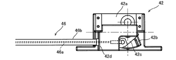
- FIG. 6 is an explanatory diagram showing the configuration of the lock unit 42.
- FIGS. 7A to 7D are explanatory views for explaining the operation of the lock unit 42.
- FIG. The lock unit 42 is a device that is controlled by the control device 70 to switch between the unlocked state of the door lock device 40 and the locked state of the door lock device 40.
- the unlocked state of the door lock device 40 is a state in which the input of the operation force to the door lock device 40 by the unlatch unit 41 is valid, and corresponds to a state in which the closed state of the side door 1 can be released.
- the locked state of the door lock device 40 is a state in which the input of the operation force to the door lock device 40 by the unlatch unit 41 is invalidated, and corresponds to a state in which releasing the closed state of the side door 1 is prohibited. .
- the lock unit 42 includes a lock motor 42a, a motor lever 42b coupled to the output shaft of the lock motor 42a, and a lock lever 42c pivotally supported on a rotation shaft different from the motor lever 42b.
- the front end of the motor lever 42b is formed as a substantially U-shaped movable piece 42b1, and is configured to rotate the lock lever 42c by engaging with an engagement pin 42c1 disposed on the lock lever 42c. ing.
- a second cable device 46 that connects the lock lever 42c and the door lock device 40 to each other is connected to the lock lever 42c.
- the second cable device 46 includes an inner cable 46a and a tubular outer cable 46b.
- the inner cable 46a is inserted into the hollow of the outer cable 46b, and can move inside.
- One end of the outer cable 46 b is fixed to the cable holding portion 42 d of the lock unit 42, and the other end is fixed to the door lock device 40.
- One end of the inner cable 46 a is connected to the lock lever 42 c, and the other end is connected to the door lock device 40.
- the lock lever 42c When the motor lever 42b is in the initial position (FIG. 7A), the lock lever 42c is in the lock position. In this case, the door lock device 40 is in a locked state. In this locked state, the operation to the door lock device 40 by the unlatch unit 41 is canceled, so that the opening of the side door 1 is restricted.
- the lock motor 42a rotates in a forward direction by a certain amount.
- the rotation of the lock motor 42a causes the motor lever 42b to rotate in the first direction (counterclockwise in FIGS. 7A to 7D) to the first rotation position (FIG. 7B).
- one end of the movable piece 42b1 of the motor lever 42b is engaged with the engagement pin 42c1 of the lock lever 42c, whereby the engagement pin 42c1 is pushed out, and the lock lever 42c reaches the unlock position (FIG. 7B).
- Rotate When the lock lever 42c rotates to the unlock position, the inner cable 46a connected to the lock lever 42c is pulled.
- the door lock device 40 connected to the other end of the inner cable 46a is operated, and the door lock device 40 is unlocked.
- the operation to the door lock device 40 by the unlatch unit 41 is effective, so that the side door 1 can be opened.
- the lock motor 42a rotates by a certain amount in the reverse direction.
- the rotation of the lock motor 42a causes the motor lever 42b to rotate to the initial position in the second direction (clockwise direction in FIGS. 7A to 7D). Since the movable piece 42b1 of the motor lever 42b rotates without engaging with the engaging pin 42c1 of the lock lever 42c, only the motor lever 42b returns to the initial position (FIG. 7C). Therefore, the lock lever 42c maintains the unlock position.
- the lock motor 42a rotates in a reverse direction by a certain amount.
- the rotation of the lock motor 42a causes the motor lever 42b to rotate in the second direction (clockwise direction in FIGS. 7A to 7D) to the second rotation position (FIG. 7D).
- the other end of the movable piece 42b1 of the motor lever 42b is engaged with the engagement pin 42c1 of the lock lever 42c, whereby the engagement pin 42c1 is pushed out, and the lock lever 42c is moved to the locked position (FIG. 7 (d)). Rotate.
- the operation handle 43 operates the door lock device 40 by a user's manual operation to release the closed state of the side door 1. As described above, release of the closed state of the side door 1 is performed by operating the door lock device 40 by the unlatch unit 41. However, assuming a failure of the unlatch unit 41, an operation handle 43 for manual operation is provided.
- the operation handle 43 is provided in the vicinity of the door assist grip 3d on the upper surface of the door armrest 3c. When viewed from the inside of the vehicle compartment, the operation handle 43 is covered with the door assist grip 3d, so that the operation handle 43 can be arranged in a state that is not easily noticeable.
- the operation handle 43 When the operation handle 43 is rotated from the closed position to the open position, the third cable device connected to the operation handle 43 is pulled. Thereby, the movable point of the door lock apparatus 40 connected with the other end of the 3rd cable apparatus is operated. By this operation, the engagement state between the latch 40a and the vehicle body is released (unlatched state). That is, by pulling up the operation handle 43 and inputting an operation force to the door lock device 40, the closed state of the side door 1 by the door lock device 40 is released.
- the illumination unit 50 is provided to guide the direction of the swipe operation with illumination.
- the illumination unit 50 is composed of a plurality of LEDs, seven LEDs 51 to 57 in this embodiment.
- the swipe operation corresponds to an operation of continuously tracing the swipe operation portion 3e from the upper side toward the lower side toward the door assist grip 3d.
- the seven LEDs 51 to 57 are arranged at a predetermined pitch from the upper end of the swipe operation portion 3e to the lower end of the door assist grip 3d.
- four LEDs 51 to 53 are arranged from the upper end to the lower end of the swipe operation unit 3e, and three LEDs 54 to 57 are arranged from the upper end to the lower end of the door assist grip 3d.
- the seven LEDs 51 to 57 are sequentially lit from the upper end of the swipe operation portion 3e to the lower end of the door assist grip 3d, so that the direction of the swipe operation can be guided.
- the half door sensor 60 is a sensor that detects the half door of the side door 1. Specifically, the half door sensor 60 detects whether or not the opening angle of the side door 1 is equal to or greater than a threshold value for detecting the half door.
- the control device 70 is a device that controls the vehicle door control device 10.
- the control device 70 mainly includes a control unit 71, a capacitance sensor input circuit 72, a door switch input circuit 73, a motor drive circuit 74, an LED drive circuit 75, and a half-door sensor input circuit 76.
- control unit 71 performs a swipe operation in which the user's contact moves to the door assist grip 3d along the swipe operation unit 3e based on the detection results of the first sensor 21 to the third sensor 23. Is determined, the closed state of the side door 1 by the door lock device 40 is released.
- the capacitance sensor input circuit 72 receives sensor signals from the first sensor 21, the second sensor 22, and the third sensor 23, respectively.
- the sensor signal input to the capacitance sensor input circuit 72 is output to the control unit 71.
- the door switch input circuit 73 receives switch signals from the lock switch 31 and the unlock switch 32.
- the switch signal input to the door switch input circuit 73 is output to the control unit 71.
- the motor drive circuit 74 rotationally drives the unlatch motor 41a of the unlatch unit 41 and the lock motor 42a of the lock unit 42 in response to a control signal from the control unit 71.
- the LED drive circuit 75 drives and drives the seven LEDs 51 to 57 in accordance with a control signal from the control unit 71.
- the sensor signal from the half door sensor 60 is input to the half door sensor input circuit 76.
- the sensor signal input to the half door sensor input circuit 76 is output to the control unit 71.
- step S10 the control device 70 waits for input of the sensor signal of the first sensor 21 and the switch signal of the unlock switch 32.
- the standby process is terminated and the process proceeds to step S11.
- step S11 the control device 70 determines whether or not an unlock operation for operating the unlock switch 32 has been performed. Whether or not the unlocking operation is performed is determined based on whether or not a switch signal is input to the unlocking switch 32. If an unlock operation has been performed, an affirmative determination is made in step S11, and the process proceeds to step S12. On the other hand, if the unlocking operation is not performed, a negative determination is made in step S11, and the process proceeds to step S16.
- step S12 the control device 70 starts guide illumination by lighting the LEDs 51 to 57 of the illumination unit 50.
- the guide illumination guides the direction of the swipe operation by sequentially lighting the LEDs 51 to 57 from the upper end of the swipe operation portion 3e toward the lower end of the door assist grip 3d.
- the individual LEDs 51 to 57 that have been turned on are turned off after a certain time has elapsed with reference to the lighting timing, and then turned on again after a certain time has elapsed, and this operation is repeated until the guide illumination ends.
- step S13 the control device 70 starts a timer.
- step S14 the control device 70 determines whether or not the count value of the timer has exceeded the upper limit time.
- the upper limit time in step S14 indicates an effective time from when the unlock switch 32 is operated until the upper end of the swipe operation unit 3e (position of the first sensor 21) is touched. Experiments and simulations The optimal value is set through.
- an affirmative determination is made in step S14, and the process proceeds to step S15.
- a negative determination is made in step S14, and the process proceeds to step S16.
- step S15 the control device 70 ends the guide illumination.
- step S16 the control device 70 determines whether or not a contact is detected by the first sensor 21 located at the upper end of the swipe operation unit 3e. If contact is detected by the first sensor 21, an affirmative determination is made in step S16, and the process proceeds to step S17. If contact is not detected by the first sensor 21, a negative determination is made in step S16, and the process returns to step S14.
- step S ⁇ b> 17 the control device 70 starts accepting the sensor signal of the second sensor 22.
- step S18 the control device 70 resets the count value of the timer and then starts the timer again.
- step S19 the control device 70 determines whether or not the count value of the timer has exceeded the upper limit time.
- the upper limit time of step S19 indicates the effective time of the swipe operation from the upper end of the swipe operation unit 3e (arrangement position of the first sensor 21) to the lower end of the swipe operation unit 3e (arrangement position of the second sensor 22).
- the optimum value is set through experiments and simulations.
- step S20 the control device 70 determines whether or not contact is detected by the second sensor 22 located at the lower end of the swipe operation unit 3e. If contact is detected by the second sensor 22, an affirmative determination is made in step S20, and the process proceeds to step S21. If contact is not detected by the second sensor 22, a negative determination is made in step S20, and the process returns to step S19.
- step S21 the control device 70 starts accepting the sensor signal of the third sensor 23.
- step S22 the control device 70 resets the count value of the timer and then starts the timer again.
- step S23 the control device 70 determines whether or not the count value of the timer has exceeded the upper limit time.
- the upper limit time of step S23 indicates the effective time of the swipe operation from the lower end of the swipe operation portion 3e (arrangement position of the second sensor 22) to the lower end of the door assist grip 3d (arrangement position of the third sensor 23).
- the optimum value is set through experiments and simulations.
- step S24 the control device 70 determines whether contact is detected by the third sensor 23 located at the lower end of the door assist grip 3d. If contact is detected by the third sensor 23, an affirmative determination is made in step S24, and the process proceeds to step S25. If contact is not detected by the third sensor 23, a negative determination is made in step S24, and the process returns to step S23.
- step S25 the control device 70 determines whether or not the door lock device 40 is unlocked. If the door lock device 40 is in the unlocked state, an affirmative determination is made in step S25, and the process proceeds to step S27. On the other hand, when the door lock device 40 is in the locked state, a negative determination is made in step S25, and the process proceeds to step S26.
- step S26 the control device 70 operates the lock unit 42 to switch the door lock device 40 to the unlocked state.
- step S27 the control device 70 operates the unlatch unit 41 to switch the door lock device 40 to the unlatched state. That is, the closed state of the side door 1 by the door lock device 40 is released.
- step S28 the control device 70 refers to the sensor signal from the half door sensor 60 and determines whether or not the opening angle of the side door 1 is equal to or greater than a threshold value for detecting the half door. If the opening angle of the side door 1 is greater than or equal to the threshold value, an affirmative determination is made in step S28, and the process proceeds to step S29. On the other hand, when the opening angle of the side door 1 is less than the threshold value, a negative determination is made in step S28, and the process returns to step S28.
- step S29 the control device 70 stops the operation of the unlatch unit 41.
- the vehicle door control device 10 includes the swipe operation unit 3e provided on the vehicle interior side of the side door 1, and at least the swipe operation unit 3e, and is provided along the swipe operation unit 3e.
- the swipe operation is detected based on the detection unit 20 that detects the swipe operation for moving the (human body), the door lock device 40 that holds the closed state of the side door 1, and the detection result of the detection unit 20, And a control device 70 for releasing the closed state of the side door 1 by the lock device 40.
- the door closing state by the door lock device 40 is released, and the side door 1 can be opened.
- the swipe operation since it is necessary to trace a certain range by hand, a clear operation intention of the user is required. Therefore, the closed state of the side door 1 is maintained even when the user simply touches the swipe operation unit 3e or the door assist grip 3d.
- the control is executed with a swipe operation that is the user's intentional operation, and therefore the user's intention to operate can be appropriately reflected.
- the vehicle door control device 10 further includes a door assist grip 3d that is provided on the vehicle interior side of the side door 1 and serves as a handle when the door is opened and closed.
- the swipe operation unit 3e is shaped to be continuous with the door assist grip 3d. Then, when the control device 70 determines a swipe operation to move to the door assist grip 3d along the swipe operation portion 3e, the control device 70 releases the door closing state of the door by the door lock device 40.
- the hand moves from the swipe operation unit 3e to the door assist grip 3d by the swipe operation. Accordingly, the hand moves in a natural manner to the door assist grip 3d which becomes a handle when the side door 1 is opened in accordance with the door closing state release operation (swipe operation) by the door lock device 40. Thereby, the release operation of the closed state by the door lock device 40 and the opening operation of the side door 1 can be continuously performed with a simple movement using only one hand.
- the vehicle door control device 10 further includes an illumination unit 50 that is provided in the swipe operation unit 3e and the door assist grip 3d and guides the direction of the swipe operation with illumination.
- the detection part 20 is provided in the door assist grip 3d, the detection part 20 should just be provided in the swipe operation part 3e at least.
- the control device 70 determines a swipe operation for moving the swipe operation unit 3e toward the door assist grip 3d, the control device 70 releases the door closing state of the door by the door lock device 40.
- the illumination unit 50 may be provided at least in the swipe operation unit 3e.
- the door lock device 40 is configured to be able to switch between a locked state and an unlocked state in accordance with a user operation. Then, when the door lock device 40 is operated from the locked state to the unlocked state, the control device 70 controls the illumination unit 50 to guide the direction of the swipe operation with illumination (guide illumination).
- guidance by the illumination unit 50 is executed in conjunction with a scene where the side door 1 is opened. Thereby, a guide can be appropriately executed according to the user's operation timing.
- the door lock device 40 includes a latch 40a that holds the door closed by engaging with the vehicle body.
- the control device 70 releases the latch 40a when detecting a swipe operation.
- the closed state of the side door 1 can be appropriately released.
- control device 70 continues to release the latch 40a until the opening angle of the side door 1 reaches a threshold value or more.
- the release of the latch 40a is continued until the latch 40a is completely released from the vehicle body. Thereby, the user can appropriately perform the opening operation of the side door 1.
- the vehicle door control device 10 of the present embodiment further includes an operation handle 43 that is provided on the vehicle interior side of the side door 1 and that can be operated by the user.
- the operation handle 43 is connected to the door lock device 40 and releases the latch 40a according to the handle operation.
- the latch 40a can be released by using the operation handle 43. As a result, a manual release operation is possible, so that an emergency operation method can be provided.
- the detection unit 20 is configured by a capacitance sensor that detects a user's contact state based on a change in capacitance.
- control device 70 can accept sensor input only for the most upstream capacitance sensor 21 in the direction of the swipe operation, and the downstream capacitance sensors 22 and 23 can be swiped by the user.
- the sensor input is sequentially switched according to the operation detection status.
- the detection unit 20 that detects a swipe operation includes a plurality of capacitance sensors 21 to 23.
- the detection unit 20 can widely apply a configuration for detecting a swipe operation accompanying movement of the user's hand, and can be realized by a single capacitance sensor in addition to using a plurality of capacitance sensors. May be. It is also possible to use a sensor other than the capacitance sensor.
- the vehicle door control device has been described above, but the present invention is not limited to the above-described embodiment, and various modifications can be made within the scope of the present invention. Nor. Moreover, although the apparatus applied to a side door was demonstrated in embodiment mentioned above, the vehicle door control apparatus which concerns on this embodiment is applicable to various vehicle doors including a back door.
- the swipe operation part is shaped to be continuous with the door assist grip.
- it is not limited to this form as long as it is shaped so as to be continuous with the handle portion that opens the side door.
- the swipe operation portion may be formed at the vehicle front position of the door armrest.
- the swipe operation unit may be modeled as a dedicated part on the door armrest, or may be a part of modeling of the door armrest.
- a concave pocket provided on the upper surface of the door armrest may be used as a handle, and a swipe operation part may be combined with this pocket.
- the door assist grip when the door assist grip is shaped so as to be continuous with the pocket portion, the door assist grip can be used as a swipe operation portion.
- a swipe operation part should just be set ahead of the pocket part in a door armrest.
- the swipe operation unit may be modeled as a dedicated part on the door armrest, or may be a part of modeling of the door armrest.
- the swipe operation part is disposed on the vehicle front side or the upper side with respect to the handle part.
- the hand moves in a natural manner from the swipe operation on the swipe operation unit to the handle portion. Therefore, a series of movements of the door closing device releasing operation and the side door opening operation can be performed with good operability.
- the swipe operation part is independently modeled so as to be continuous with the handle part that opens the side door.
- the swipe operation unit does not have to be entirely modeled, and may be set so as to straddle part or all of the model of the handle part.
- the swipe operation unit may be set by superimposing a part or all of the modeling using the modeling of the handle part. Even in such a configuration, with the release operation of the closed state by the door lock device, the hand moves to the handle part that opens the side door in a natural manner, or the hand part is held. Move as it is. Thereby, it is possible to continuously perform the door closing state releasing operation and the side door opening operation with a simple movement using only one hand.
- the handle portion and the swipe operation portion do not need to be separated and independent from each other in terms of modeling, but the vehicle of the door so that the respective functions are adjacent to each other or overlap each other. What is necessary is just to be provided in the indoor side.
Landscapes
- Engineering & Computer Science (AREA)
- Mechanical Engineering (AREA)
- Lock And Its Accessories (AREA)
- User Interface Of Digital Computer (AREA)
Abstract
車両用ドア制御装置(10)は、サイドドアの車両室内側に設けられたスワイプ操作部と、少なくともスワイプ操作部に設けられ、スワイプ操作部に沿って手を移動させるスワイプ操作を検知する検知部(20)と、サイドドアの閉扉状態を保持するドアロック装置(40)と、検知部(20)の検知結果に基づいて、スワイプ操作を検知した場合に、ドアロック装置(40)によるサイドドアの閉扉状態を解除する制御装置(70)と、を有している。
Description
本発明は、車両用ドア制御装置に関する。
特許文献1に記載のドアロック装置は、ドアを閉状態に保持するラッチ部材と、ラッチ部材をロックするボール部材と、ドアグリップへの接触を検知してドア開指示信号を発生するロック解除指示手段と、ドア開指示信号に応じてボール部材によるラッチ部材のロックを解除するロック解除手段と、を有している。このドアロック装置によれば、ユーザーがドアグリップを掴むと、ドアグリップへの接触が検知されてドア開指示信号が発生する。これにより、ラッチ部材のロックが解除され、ドアを開方向に駆動することによりドアを開けることができる。したがって、ドアグリップを掴むというドアを開放するための人の操作に応答するので、意識的な操作を必要としない。
ところで、特許文献1に記載のドアロック装置では、単一のセンサー電極をドアグリップに配置して、静電容量の変化からドアグリップへの接触を検知している。そのため、ユーザーがドア開放を意図することなくドアグリップに触れた場合でも、ラッチ部材のロックが解除される。
本発明の実施例によれば、車両用ドア制御装置において、ユーザーの操作意思を適切に反映することができる。
本発明の実施例によれば、車両用ドア制御装置は、ドアの車両室内側に設けられたスワイプ操作部と、少なくともスワイプ操作部に設けられ、スワイプ操作部に沿って人体を移動させるスワイプ操作を検知する検知部と、ドアの閉扉状態を保持するドアロック装置と、検知部の検知結果に基づいてスワイプ操作を判断した場合に、ドアロック装置によるドアの閉扉状態を解除するコントローラーと、を有している。
ここで、車両用ドア制御装置は、ドアの車両室内側に設けられ、ドア開閉時に持ち手となる持ち手部をさらに有していてもよい。この場合、スワイプ操作部は、持ち手部に連続するように造形されており、コントローラーは、スワイプ操作部を持ち手部に向かって移動するスワイプ操作を判断した場合に、ドアロック装置によるドアの閉扉状態を解除することが好ましい。
また、車両用ドア制御装置は、ドアの車両室内側に設けられ、ドア開閉時に持ち手となる持ち手部をさらに有していてもよい。この場合、スワイプ操作部は、持ち手部の造形の一部若しくは全部に跨がるように設定されている、又は持ち手部の造形の一部若しくは全部に重畳して設定されていることが好ましい。
また、車両用ドア制御装置は、少なくともスワイプ操作部に設けられ、スワイプ操作の方向を照明でガイドする照明部をさらに有することが好ましい。
また、車両用ドア制御装置は、ドアロック装置は、車体に対して係合することでドアの閉扉状態を保持するラッチを備え、コントローラーは、スワイプ操作を判断した場合に、ラッチの解除を行うとともに、ドアの開放角度が閾値以上に到達するまで、ラッチの解除を継続することが好ましい。
また、車両用ドア制御装置は、検知部は、ユーザーの接触を静電容量の変化で検知する静電容量センサーであることが好ましい。この場合、静電容量センサーは、スワイプ操作の方向にかけて上流側から下流側に間隔を隔てて複数配置されていることが好ましい。そして、コントローラーは、最上流の静電容量センサーについてのみセンサー入力を受付可能とし、下流側の静電容量センサーについては、ユーザーのスワイプ操作の検知状況に従ってセンサー入力を受付可能へと順次切り替えることが好ましい。
本発明の実施例によれば、ユーザーの操作意思を適切に反映することができる車両用ドア制御装置及び車両用制御装置を提供することができる。
以下、本実施形態に係る車両用ドア制御装置10を車両のサイドドア1に適用して説明する。ここで、図1は、本実施形態に係る車両用ドア制御装置10が適用されるサイドドア1を示す正面図である。図2は、サイドドア1を示す斜視図である。図3は、車両用ドア制御装置10の構成を示すブロック図である。図4は、サイドドア1の要部を拡大して示す正面図である。
サイドドア1は、フロントピラーとセンタピラーとの間のドア開口部を開閉するフロント側のサイドドアである。サイドドア1は、その前端部がヒンジ機構(図示せず)を介して車体と連結され、ヒンジ機構を中心に回動可能に構成されている。サイドドア1は、ドア本体2と、ドアトリム3とを主体に構成されている。
ドア本体2は、車両室外側のドア半体を形成するドアアウタパネルと、車両室内側のドア半体を形成するドアインナパネルとを備えている。ドアアウタパネル及びドアインナパネルは、周縁部同士が接合され、その内部に空間が形成された閉断面に構成されている。
ドアトリム3は、車両室内を装飾する内装部品であり、ドア本体2の車両室内側に、当該ドア本体2を覆うように設けられている。ドアトリム3の主要部は、車両上下方向及び車両前後方向に沿う面形状を備えている。ドアトリム3において、ドアトリム3の車両上下方向の下方位置にはドアポケット3aが設けられ、このドアポケット3aよりも前方位置にはスピーカーグリル3bが設けられている。ドアトリム3の車両上下方向の中央位置には、ドアアームレスト3cが設けられている。
ドアアームレスト3cの前方には、サイドドア1の開閉時に持ち手となるドアアシストグリップ(持ち手部)3dが設けられている。ドアアシストグリップ3dは、車両前方から車両後方にかけて下向きとなるように斜め形状に配設されている。ドアアシストグリップ3dの上端には、ドアアシストグリップ3dに連続するように連続的に造形されたスワイプ操作部3eが設けられている。
スワイプ操作部3eは、ドアトリム3に対して向き合うように縦壁状に配置されており、ドアトリム3との間に隙間を形成している。この隙間に指を差し入れた格好でスワイプ操作部3eの造形に沿って上方から下方へと手を移動させることで、ユーザーは、スワイプ操作部3eを利用したスワイプ操作を行うことができる。また、スワイプ操作部3eはドアアシストグリップ3dに連続して造形されているため、スワイプ操作からの一連の動きで、ドアアシストグリップ3dへと手を移動させることができる。本実施形態においては、スワイプ操作部3eに沿ってドアアシストグリップ3dへと手を移動させるスワイプ操作が、サイドドア1を開放するための操作として採用されている。
車両用ドア制御装置10は、検知部20と、スイッチ部30と、ドアロック装置40と、照明部50と、半ドアセンサー60と、制御装置70とを主体に構成されている。
検知部20は、スワイプ操作部3eに沿って手(人体)を接触移動(接近した状態での移動も含む)させるスワイプ操作を検知するものであり、複数の静電容量センサー、本実施形態では3つの静電容量センサー21~23から構成されている。個々の静電容量センサー21~23は、静電容量の変化に基づいてユーザーの接触(接近も含む)を検知する。図4に示すように、1つ目の静電容量センサー21(以下必要に応じて「第1センサー21」という)がスワイプ操作部3eの上端側に配置され、2つ目の静電容量センサー22(以下必要に応じて「第2センサー22」という)がスワイプ操作部3eの下端側に配置され、3つ目の静電容量センサー23(以下必要に応じて「第3センサー23」という)がドアアシストグリップ3dの下端側に配置されている。これらの第1センサー21から第3センサー23の検知結果に応じて、すなわち、第1センサー21から第3センサー23にかけてユーザーの接触が順次検知されることで、スワイプ操作部3eに沿ってドアアシストグリップ3dへと至るスワイプ操作を検知することができる。したがって、スワイプ操作の方向を基準に、最上流に第1センサー21が配置され、その下流に第2センサー22が配置され、さらに下流(最下流)に第3センサー23が配置されることとなる。
スイッチ部30は、ロックスイッチ31及びアンロックスイッチ32から構成されている。ロックスイッチ31及びアンロックスイッチ32は、ドアトリム3の造形面の一部に配置されている。ロックスイッチ31は、ドアロック装置40をロック状態に操作するためのスイッチである。アンロックスイッチ32は、ドアロック装置40をアンロック状態に操作するためのスイッチである。
ドアロック装置40は、サイドドア1の閉扉状態を保持する装置であり、車体に対して係合するラッチ40aを備えている。ドアロック装置40には、ケーブル装置を介して、アンラッチユニット41、ロックユニット42及び操作ハンドル43が接続されている。
図5は、アンラッチユニット41の構成を示す説明図である。アンラッチユニット41は、制御装置70に制御されて、ドアロック装置40によるサイドドア1の閉扉状態を解除する装置である。アンラッチユニット41は、アンラッチモーター41aと、アンラッチモーター41aの出力軸に連結されたアンラッチレバー41bとで構成されている。アンラッチレバー41bには、アンラッチレバー41bとドアロック装置40とを相互に連結する第1ケーブル装置45が接続されている。
第1ケーブル装置45は、インナーケーブル45aと、チューブ状のアウターケーブル45bとから構成されている。インナーケーブル45aは、アウターケーブル45bの中空内に挿通されており、その内部を移動することができる。アウターケーブル45bの一方の端部は、アンラッチユニット41のケーブル保持部41cに固定され、その他方の端部は、ドアロック装置40に固定されている。インナーケーブル45aの一方の端部は、アンラッチレバー41bに連結され、その他方の端部は、ドアロック装置40のラッチ40aを操作する可動点に連結されている。
アンラッチユニット41が動作していない場合、アンラッチレバー41bは初期位置(図示せず)となる。アンラッチレバー41bが初期位置の状態では、インナーケーブル45aは引っ張られた状態とはなっておらず、ドアロック装置40の可動点についても操作は行われない。この場合、ドアロック装置40のラッチ40aは車体と係合した係合状態(ラッチ状態)となっている。このため、サイドドア1は閉扉状態で保持される。
そして、アンラッチユニット41が動作すると、アンラッチモーター41aが順方向へと一定量だけ回転する。アンラッチモーター41aの回転によりアンラッチレバー41bが初期位置からアンラッチ位置まで回動すると、アンラッチレバー41bに連結されたインナーケーブル45aが引っ張られる(図5に示す状態)。これにより、インナーケーブル45aの他端に連結されたドアロック装置40の可動点が操作される。この操作により、ラッチ40aと車体との係合状態が解除される(アンラッチ状態)。すなわち、アンラッチユニット41が動作してドアロック装置40に操作力を入力することで、ドアロック装置40によるサイドドア1の閉扉状態が解除される。
一方、アンラッチユニット41が動作を停止すると、アンラッチモーター41aが逆方向へと一定量だけ回転する。アンラッチモーター41aの回転によりアンラッチレバー41bがアンラッチ位置から初期位置まで回動すると、アンラッチレバー41bに連結されたインナーケーブル45aが戻される。これにより、インナーケーブル45aの他端に連結されたドアロック装置40の可動点が初期状態へと操作される。この操作により、ラッチ40aは、車体に対して係合可能なラッチ状態となる。このため、サイドドア1が閉扉された状態であれば、その閉扉状態が保持される。
図6は、ロックユニット42の構成を示す説明図である。図7(a)~(d)は、ロックユニット42の動作を説明する説明図である。ロックユニット42は、制御装置70に制御されて、ドアロック装置40のアンロック状態と、ドアロック装置40のロック状態とを切り替える装置である。ドアロック装置40のアンロック状態は、アンラッチユニット41によるドアロック装置40への操作力の入力を有効とする状態であり、サイドドア1の閉扉状態を解除することが可能な状態に相当する。一方、ドアロック装置40のロック状態は、アンラッチユニット41によるドアロック装置40への操作力の入力を無効とする状態であり、サイドドア1の閉扉状態を解除することを禁止する状態に相当する。
ロックユニット42は、ロックモーター42aと、ロックモーター42aの出力軸に連結されたモーターレバー42bと、モーターレバー42bとは異なる回転軸に軸支されたロックレバー42cとで構成されている。モーターレバー42bの先端は略U字状の可動片42b1として形成されており、ロックレバー42cに配設された係合ピン42c1と係合することで、ロックレバー42cを回動させるように構成されている。
ロックレバー42cには、ロックレバー42cとドアロック装置40とを相互に連結する第2ケーブル装置46が接続されている。第2ケーブル装置46は、インナーケーブル46aと、チューブ状のアウターケーブル46bとから構成されている。インナーケーブル46aは、アウターケーブル46bの中空内に挿通されており、その内部を移動することができる。アウターケーブル46bの一方の端部は、ロックユニット42のケーブル保持部42dに固定され、その他方の端部は、ドアロック装置40に固定されている。インナーケーブル46aの一方の端部は、ロックレバー42cに連結され、その他方の端部は、ドアロック装置40に連結されている。
モーターレバー42bが初期位置にある状態において(図7(a))、ロックレバー42cはロック位置に存在する。この場合、ドアロック装置40はロック状態となっている。このロック状態においては、アンラッチユニット41によるドアロック装置40への操作がキャンセルされるので、サイドドア1の開放が規制される。
まず、ロック状態からアンロック状態への切替動作について説明する。ロックユニット42が動作することで、ロックモーター42aが順方向へと一定量だけ回転する。ロックモーター42aの回転により、モーターレバー42bが第1方向(図7(a)~(d)において反時計回り方向)にかけて第1回動位置(図7(b))まで回動する。この際、モーターレバー42bの可動片42b1の一端がロックレバー42cの係合ピン42c1に係合することで係合ピン42c1が押し出され、ロックレバー42cがアンロック位置(図7(b))まで回動する。ロックレバー42cがアンロック位置まで回動すると、ロックレバー42cに連結されたインナーケーブル46aが引っ張られる。インナーケーブル46aが引っ張られると、インナーケーブル46aの他端に連結されたドアロック装置40が操作され、ドアロック装置40がアンロック状態となる。このアンロック状態においては、アンラッチユニット41によるドアロック装置40への操作が有効とされるので、サイドドア1の開放が可能となる。
そして、ロックモーター42aは、逆方向へと一定量だけ回転する。ロックモーター42aの回転により、モーターレバー42bが第2方向(図7(a)~(d)において時計回り方向)にかけて初期位置まで回動する。モーターレバー42bは、その可動片42b1がロックレバー42cの係合ピン42c1に係合することなく回動するので、モーターレバー42bのみが初期位置まで復帰する(図7(c))。したがって、ロックレバー42cはアンロック位置を維持する。
つぎに、アンロック状態からロック状態への切替動作について説明する。ロックユニット42が動作することで、ロックモーター42aが逆方向へと一定量だけ回転する。ロックモーター42aの回転により、モーターレバー42bが第2方向(図7(a)~(d)において時計回り方向)にかけて第2回動位置(図7(d))まで回動する。この際、モーターレバー42bの可動片42b1の他端がロックレバー42cの係合ピン42c1に係合することで係合ピン42c1が押し出され、ロックレバー42cがロック位置(図7(d))まで回動する。ロックレバー42cがロック位置まで回動すると、ロックレバー42cに連結されたインナーケーブル46aが押し出される。インナーケーブル46aが押し出されると、インナーケーブル46aの他端に連結されたドアロック装置40が操作され、ドアロック装置40がロック状態となる。このロック状態においては、アンラッチユニット41によるドアロック装置40への操作がキャンセルされるので、サイドドア1の開放が規制される。
そして、ロックモーター42aは、順方向へと一定量だけ回転する。ロックモーター42aの回転により、モーターレバー42bが第1方向(図7(a)~(d)において反時計回り方向)にかけて初期位置まで回動する。モーターレバー42bは、その可動片42b1がロックレバー42cの係合ピン42c1に係合することなく回動するので、モーターレバー42bのみが初期位置まで復帰する(図7(a))。したがって、ロックレバー42cはロック位置を維持する。
操作ハンドル43は、ユーザーの手動操作によりドアロック装置40を操作して、サイドドア1の閉扉状態を解除するものである。上述したように、サイドドア1の閉扉状態の解除は、アンラッチユニット41によってドアロック装置40を操作することにより行われる。ただし、アンラッチユニット41の故障等を想定して、手動操作のための操作ハンドル43が設けられている。操作ハンドル43は、ドアアームレスト3cの上面のドアアシストグリップ3dの近傍に設けられている。車両室内側から眺めた際には、ドアアシストグリップ3dにより操作ハンドル43が覆われるので、操作ハンドル43を目立ちにくい状態で配置することができる。
操作ハンドル43は、図示しないピンにより後端が軸支されており、後端を中心として前端側が回動自在に構成されている。操作ハンドル43は、ドアアームレスト3cと面一になる閉位置と、前端側がドアアームレスト3cから引き上げられた開位置との範囲で回動する。この操作ハンドル43は、インナーケーブル及びアウターケーブルを含む第3ケーブル装置を介してドアロック装置40と相互に連結されている。
操作ハンドル43が閉位置から開位置まで回動操作されると、操作ハンドル43に連結された第3ケーブル装置が引っ張られる。これにより、第3ケーブル装置の他端に連結されたドアロック装置40の可動点が操作される。この操作により、ラッチ40aと車体との係合状態が解除される(アンラッチ状態)。すなわち、操作ハンドル43を引き上げてドアロック装置40に操作力を入力することで、ドアロック装置40によるサイドドア1の閉扉状態が解除される。
照明部50は、スワイプ操作の方向を照明でガイドするために設けられている。照明部50は、複数のLED、本実施形態では7つのLED51~57から構成されている。上述した通り、スワイプ操作は、ドアアシストグリップ3dに向かってスワイプ操作部3eを上方から下方へと連続的になぞる操作に相当する。図4に示すように、7つのLED51~57は、スワイプ操作部3eの上端からドアアシストグリップ3dの下端にかけて所定のピッチで配置されている。具体的には、スワイプ操作部3eの上端から下端にかけて4つのLED51~53が配置され、ドアアシストグリップ3dの上端から下端にかけて3つのLED54~57が配置されている。7つのLED51~57が、スワイプ操作部3eの上端からドアアシストグリップ3dの下端にかけて順次点灯することで、スワイプ操作の方向をガイドすることができる。
半ドアセンサー60は、サイドドア1の半ドアを検知するセンサーである。具体的には、半ドアセンサー60は、サイドドア1の開放角度が半ドアを検知する閾値以上であるか否かを検知する。
制御装置70は、車両用ドア制御装置10を制御する装置である。制御装置70は、制御部71、静電容量センサー入力回路72、ドアスイッチ入力回路73、モーター駆動回路74、LED駆動回路75及び半ドアセンサー入力回路76を主体に構成されている。
制御部71は、各入力回路72,73,76から入力される情報に基づいて、各駆動回路74,75に制御信号を出力する。この制御信号を通じて、アンラッチユニット41の動作状態、ロックユニット42の動作状態、照明部50を構成する各LED51~57の点灯状態が制御される。制御部71としては、CPU、ROM、RAM、I/Oインターフェースを主体に構成されたマイクロコンピュータを用いることができる。CPUは、制御プログラムに従い、各種の制御を行う(プロセッサ)。ROMは、CPUが実行するプログラム、又はそのプログラムを実行するために必要なデータを記憶する。RAMは、CPUがプログラムを実行する際の作業領域である。
本実施形態との関係において、制御部71は、第1センサー21から第3センサー23の検知結果に基づいて、ユーザーの接触がスワイプ操作部3eに沿ってドアアシストグリップ3dへと移動するスワイプ操作を判断した場合に、ドアロック装置40によるサイドドア1の閉扉状態を解除する。
静電容量センサー入力回路72は、第1センサー21、第2センサー22及び第3センサー23のセンサー信号がそれぞれ入力される。静電容量センサー入力回路72に入力されたセンサー信号は、制御部71に出力される。
ドアスイッチ入力回路73は、ロックスイッチ31及びアンロックスイッチ32のスイッチ信号が入力される。ドアスイッチ入力回路73に入力されたスイッチ信号は、制御部71に出力される。
モーター駆動回路74は、制御部71からの制御信号に応じて、アンラッチユニット41のアンラッチモーター41a及びロックユニット42のロックモーター42aを回転駆動する。
LED駆動回路75は、制御部71からの制御信号に応じて、7つのLED51~57を点灯駆動する。
半ドアセンサー入力回路76は、半ドアセンサー60からのセンサー信号が入力される。半ドアセンサー入力回路76に入力されたセンサー信号は、制御部71に出力される。
以下、本実施形態に係る車両用ドア制御装置10の動作を説明する。ここで、図8及び図9は、本実施形態に係る車両用ドア制御装置10の動作を説明するフローチャートである。このフローチャートに示す処理は、制御装置70により実行される。このフローチャートの開始時においては、検知部20の3つの静電容量センサー21~23のうち第1センサー(スワイプ操作の方向において最上流の静電容量センサー)21についてのみ、センサー入力(センサー信号)の受付が可能となっている。
まず、ステップS10において、制御装置70は、第1センサー21のセンサー信号及びアンロックスイッチ32のスイッチ信号の入力を待機する。信号の入力があると待機処理を終了し、ステップS11に進む。
ステップS11において、制御装置70は、アンロックスイッチ32を操作するアンロック操作がなされたか否かを判断する。アンロック操作の有無は、アンロックスイッチ32のスイッチ信号の入力の有無で判断される。アンロック操作がなされた場合には、ステップS11において肯定判定され、ステップS12に進む。一方、アンロック操作がなされない場合には、ステップS11において否定判定され、ステップS16に進む。
ステップS12において、制御装置70は、照明部50の各LED51~57を点灯駆動することで、ガイド照明を開始する。ガイド照明は、スワイプ操作部3eの上端からドアアシストグリップ3dの下端に向かってLED51~57を順次点灯することで、スワイプ操作の方向をガイドするものである。点灯された個々のLED51~57は、その点灯タイミングを基準に一定時間経過後に消灯され、その後一定時間経過した後に再度点灯され、ガイド照明が終了するまでこの動作が繰り返される。
ステップS13において、制御装置70は、タイマーを開始する。
ステップS14において、制御装置70は、タイマーのカウント値が上限時間を超過したか否かを判断する。ステップS14の上限時間は、アンロックスイッチ32を操作してからスワイプ操作部3eの上端(第1センサー21の配置位置)に接触操作がなされるまでの有効時間を示すものであり、実験やシミュレーションを通じて最適値が設定されている。タイマーのカウント値が上限時間を超過した場合には、ステップS14において肯定判定され、ステップS15に進む。一方、タイマーのカウント値が上限時間を超過していない場合には、ステップS14において否定判定され、ステップS16に進む。
ステップS15において、制御装置70は、ガイド照明を終了する。
ステップS16において、制御装置70は、スワイプ操作部3eの上端に位置する第1センサー21で接触が検知されたか否かを判断する。第1センサー21で接触が検知された場合には、ステップS16で肯定判定され、ステップS17に進む。第1センサー21で接触が検知されない場合には、ステップS16で否定判定され、ステップS14に戻る。
ステップS17において、制御装置70は、第2センサー22のセンサー信号の受付を開始する。
ステップS18において、制御装置70は、タイマーのカウント値をリセットした上で、タイマーを改めて開始する。
ステップS19において、制御装置70は、タイマーのカウント値が上限時間を超過したか否かを判断する。ステップS19の上限時間は、スワイプ操作部3eの上端(第1センサー21の配置位置)からスワイプ操作部3eの下端(第2センサー22の配置位置)に至るまでのスワイプ操作の有効時間を示すものであり、実験やシミュレーションを通じて最適値が設定されている。タイマーのカウント値が上限時間を超過した場合には、ステップS19において肯定判定され、ステップS15に進む。一方、タイマーのカウント値が上限時間を超過していない場合には、ステップS19において否定判定され、ステップS20に進む。
ステップS20において、制御装置70は、スワイプ操作部3eの下端に位置する第2センサー22で接触が検知されたか否かを判断する。第2センサー22で接触が検知された場合には、ステップS20で肯定判定され、ステップS21に進む。第2センサー22で接触が検知されない場合には、ステップS20で否定判定され、ステップS19に戻る。
ステップS21において、制御装置70は、第3センサー23のセンサー信号の受付を開始する。
ステップS22において、制御装置70は、タイマーのカウント値をリセットした上で、タイマーを改めて開始する。
ステップS23において、制御装置70は、タイマーのカウント値が上限時間を超過したか否かを判断する。ステップS23の上限時間は、スワイプ操作部3eの下端(第2センサー22の配置位置)からドアアシストグリップ3dの下端(第3センサー23の配置位置)に至るまでのスワイプ操作の有効時間を示すものであり、実験やシミュレーションを通じて最適値が設定されている。タイマーのカウント値が上限時間を超過した場合には、ステップS23において肯定判定され、ステップS15に進む。一方、タイマーのカウント値が上限時間を超過していない場合には、ステップS23において否定判定され、ステップS24に進む。
ステップS24において、制御装置70は、ドアアシストグリップ3dの下端に位置する第3センサー23で接触が検知されたか否かを判断する。第3センサー23で接触が検知された場合には、ステップS24で肯定判定され、ステップS25に進む。第3センサー23で接触が検知されない場合には、ステップS24で否定判定され、ステップS23に戻る。
ステップS25において、制御装置70は、ドアロック装置40がアンロック状態であるか否かを判断する。ドアロック装置40がアンロック状態である場合には、ステップS25において肯定判定され、ステップS27に進む。一方、ドアロック装置40がロック状態である場合には、ステップS25において否定判定され、ステップS26に進む。
ステップS26において、制御装置70は、ロックユニット42を動作させて、ドアロック装置40をアンロック状態へと切り替える。
ステップS27において、制御装置70は、アンラッチユニット41を動作させて、ドアロック装置40をアンラッチ状態へと切り替える。すなわち、ドアロック装置40によるサイドドア1の閉扉状態が解除される。
ステップS28において、制御装置70は、半ドアセンサー60からのセンサー信号を参照し、サイドドア1の開放角度が半ドアを検知する閾値以上であるか否かを判断する。サイドドア1の開放角度が閾値以上である場合には、ステップS28において肯定判定され、ステップS29に進む。一方、サイドドア1の開放角度が閾値未満である場合には、ステップS28において否定判定され、ステップS28に戻る。
ステップS29において、制御装置70は、アンラッチユニット41の動作を停止させる。
このように本実施形態に係る車両用ドア制御装置10は、サイドドア1の車両室内側に設けられたスワイプ操作部3eと、少なくともスワイプ操作部3eに設けられ、スワイプ操作部3eに沿って手(人体)を移動させるスワイプ操作を検知する検知部20と、サイドドア1の閉扉状態を保持するドアロック装置40と、検知部20の検知結果に基づいて、スワイプ操作を検知した場合に、ドアロック装置40によるサイドドア1の閉扉状態を解除する制御装置70と、を有している。
この構成によれば、スワイプ操作部3eに対してスワイプ操作を行うことで、ドアロック装置40による閉扉状態が解除され、サイドドア1を開放することができる。スワイプ操作にあっては、一定の範囲を手でなぞる必要があるので、ユーザーの明確な操作意図が必要となる。そのため、単にスワイプ操作部3eやドアアシストグリップ3dに触れてしまったような場合でも、サイドドア1の閉扉状態が維持される。これにより、ユーザーの意図的な操作となるスワイプ操作をもって制御が実行されるので、ユーザーの操作意思を適切に反映することができる。
また、本実施形態において、車両用ドア制御装置10は、サイドドア1の車両室内側に設けられ、ドア開閉時に持ち手となるドアアシストグリップ3dをさらに有している。この場合、スワイプ操作部3eは、ドアアシストグリップ3dに連続するように造形されている。そして、制御装置70は、スワイプ操作部3eに沿ってドアアシストグリップ3dへと移動するスワイプ操作を判断した場合に、ドアロック装置40によるドアの閉扉状態を解除している。
この構成によれば、スワイプ操作により、スワイプ操作部3eからドアアシストグリップ3dへと手が移動する。これにより、ドアロック装置40による閉扉状態の解除操作(スワイプ操作)に伴い、サイドドア1を開放する際に持ち手となるドアアシストグリップ3dへと手が自然な形で移動する。これにより、片手のみを利用した簡単な動きで、ドアロック装置40による閉扉状態の解除操作と、サイドドア1の開放操作とを連続的に行うことができる。
また、本実施形態において、車両用ドア制御装置10は、スワイプ操作部3e及びドアアシストグリップ3dに設けられ、スワイプ操作の方向を照明でガイドする照明部50をさらに有している。
この構成によれば、照明部50の照明に沿ってスワイプ操作を行えばよいので、ユーザーの操作をガイドすることができる。これにより、ユーザーにとって分かり易い装置を提供することができる。
なお、本実施形態では、ドアアシストグリップ3dに検知部20を設けているが、検知部20は、少なくともスワイプ操作部3eに設けられていればよい。この場合、制御装置70は、スワイプ操作部3eをドアアシストグリップ3dに向かって移動するスワイプ操作を判断した場合に、ドアロック装置40によるドアの閉扉状態を解除することとなる。また、照明部50についても同様に、少なくともスワイプ操作部3eに設けられていればよい。
また、本実施形態において、ドアロック装置40は、ロック状態とアンロック状態とが、ユーザーの操作に応じて切り替え可能に構成されている。そして、制御装置70は、ドアロック装置40がロック状態からアンロック状態へと操作された場合に、照明部50を制御してスワイプ操作の方向を照明でガイドしている(ガイド照明)。
この構成によれば、サイドドア1が開放されるシーンに併せて、照明部50によるガイドが実行される。これにより、ユーザーの操作タイミングに併せて適切にガイドを実行することができる。
また、本実施形態において、ドアロック装置40は、車体に対して係合することでドアの閉扉状態を保持するラッチ40aを備えている。この場合、制御装置70は、スワイプ操作を検知した場合に、ラッチ40aの解除を行う。
この構成によれば、サイドドア1の閉扉状態を適切に解除することができる。
また、本実施形態において、制御装置70は、サイドドア1の開放角度が閾値以上に到達するまで、ラッチ40aの解除を継続する。
この構成によれば、車体に対してラッチ40aが完全に外れた状態となるまで、ラッチ40aの解除が継続されることとなる。これにより、ユーザーがサイドドア1の開放操作を適切に行うことができる。
また、本実施形態の車両用ドア制御装置10は、サイドドア1の車両室内側に設けられ、ユーザーが操作可能な操作ハンドル43をさらに有している。操作ハンドル43は、ドアロック装置40と接続されて、ハンドル操作に応じてラッチ40aの解除を行う。
この構成によれば、操作ハンドル43を利用することで、ラッチ40aの解除操作を行うことができる。これにより、手動による解除操作が可能となるので、緊急時の操作手法を提供することができる。
また、本実施形態において、検知部20は、ユーザーの接触状態を静電容量の変化で検知する静電容量センサーで構成されている。
この構成によれば、スワイプ操作部3eへの接触状態を適切に検知することができる。
また、本実施形態において、制御装置70は、スワイプ操作の方向における最上流の静電容量センサー21についてのみセンサー入力を受付可能とし、下流側の静電容量センサー22,23については、ユーザーのスワイプ操作の検知状況に従ってセンサー入力を受付可能へと順次切り替えている。
この構成によれば、スワイプ操作部3eの上端を始点とするスワイプ操作のみを適切に判断することができる。これにより、類似の操作を排除することができるので、信頼性の高い装置を提供することができる。
なお、本実施形態において、スワイプ操作を検知する検知部20は、複数の静電容量センサー21~23を備えている。しかしながら、検知部20は、ユーザーの手の移動に伴うスワイプ操作を検知する構成を広く適用することができ、複数の静電容量センサーを用いる以外にも、単一の静電容量センサーで実現してもよい。また、静電容量センサー以外のセンサーを用いることも可能である。
以上、本発明の実施形態に係る車両用ドア制御装置について説明したが、本発明は上述した実施形態に限定されることなく、その発明の範囲内において種々の変形が可能であることはいうまでもない。また、上述した実施形態では、サイドドアに適用される装置について説明したが、本実施形態に係る車両用ドア制御装置はバックドア等を含む種々の車両用ドアに適用することができる。
また、本実施形態では、スワイプ操作部をドアアシストグリップに連続するように造形している。しかしながら、サイドドアの開放を行う持ち手部に連続するように造形するものであれば、この形態に限定されない。
例えば、ドアアームレストの車両後方位置に持ち手部が設定されている車両であれば、ドアアームレストの車両前方位置にスワイプ操作部が造形されればよい。この際、スワイプ操作部は、ドアアームレストに専用の部位として造形されてもよいし、ドアアームレストの造形の一部を利用するものでもよい。
また、ドアアームレストの上面に設けられた凹状のポケット部(図2において符号「3c1」で示される部位)を持ち手部として、このポケット部に対してスワイプ操作部を組み合わせてもよい。例えば、ドアアシストグリップがポケット部に連続するように造形されている場合には、ドアアシストグリップをスワイプ操作部として利用することができる。また、ドアアシストグリップが存在しない構成のドアアームレスト、或いはドアアシストグリップが離れている構成のドアアームレストであれば、ドアアームレストにおけるポケット部前方にスワイプ操作部が設定されればよい。この際、スワイプ操作部は、ドアアームレストに専用の部位として造形されてもよいし、ドアアームレストの造形の一部を利用するものでもよい。
なお、スワイプ操作部は、持ち手部に対して車両前方側又は上側に配置されていることが好ましい。これにより、スワイプ操作部に対するスワイプ操作から持ち手部へと手が自然な形で移動することとなる。よって、ドアロック装置による閉扉状態の解除操作と、サイドドアの開放操作という一連の動きを操作性よく行うことができる。
なお、本実施形態では、スワイプ操作部は、サイドドアの開放を行う持ち手部に連続するように独立して造形されている。しかしながら、スワイプ操作部は、その全部を専用の造形としなくてもよく、持ち手部の造形の一部又は全部に跨がるように設定してもよい。また、スワイプ操作部は、持ち手部の造形を利用して、その造形の一部又は全部に重畳して設定してもよい。このような構成であっても、ドアロック装置による閉扉状態の解除操作に伴い、サイドドアを開放する持ち手部へと手が自然な形で移動する、或いは、持ち手部を握る状態へとそのまま移動する。これにより、片手のみを利用した簡単な動きで、ドアロック装置による閉扉状態の解除操作と、サイドドアの開放操作とを連続的に行うことができる。このように、本発明にあっては、持ち手部及びスワイプ操作部は、それぞれが造形的に分離独立している必要はなく、それぞれの機能が隣り合うように又は重畳するようにドアの車両室内側に設けられていればよい。
本出願は、2018年5月11日出願の日本特許出願(特願2018-092002)、に基づくものであり、その内容はここに参照として取り込まれる。
1 サイドドア
2 ドア本体
3 ドアトリム
3a ドアポケット
3b スピーカーグリル
3c ドアアームレスト
3d ドアアシストグリップ
3e スワイプ操作部
10 車両用ドア制御装置
20 検知部
21~23 静電容量センサー(第1センサー、第2センサー、第3センサー)
30 スイッチ部
31 ロックスイッチ
32 アンロックスイッチ
40 ドアロック装置
40a ラッチ
41 アンラッチユニット
41a アンラッチモーター
41b アンラッチレバー
41c ケーブル保持部
42 ロックユニット
42a ロックモーター
42b モーターレバー
42b1 可動片
42c ロックレバー
42c1 係合ピン
42d ケーブル保持部
43 操作ハンドル
45 第1ケーブル装置
46 第2ケーブル装置
50 照明部
51~57 LED
60 半ドアセンサー
70 制御装置(コントローラー)
71 制御部
72 静電容量センサー入力回路
73 ドアスイッチ入力回路
74 モーター駆動回路
75 LED駆動回路
76 半ドアセンサー入力回路
Claims (6)
- 車両用ドア制御装置であって、
ドアの車両室内側に設けられたスワイプ操作部と、
少なくとも前記スワイプ操作部に設けられ、スワイプ操作を検知する検知部と、
ドアの閉扉状態を保持するドアロック装置と、
前記検知部の検知結果に基づいて前記スワイプ操作を検知したと判断された場合に、前記ドアロック装置によるドアの閉扉を解除するコントローラーと、
を具備する、車両用ドア制御装置。 - 前記車両用ドア制御装置は、ドアの車両室内側に設けられ、ドア開閉時に持ち手となる持ち手部をさらに具備し、
前記スワイプ操作部は、前記持ち手部に連続するように配置され、
前記コントローラーは、前記持ち手部に向かって移動するスワイプ操作を検知したと判断された場合に、前記ドアロック装置によるドアの閉扉を解除する、請求項1記載の車両用ドア制御装置。 - 前記車両用ドア制御装置は、ドアの車両室内側に設けられ、ドア開閉時に持ち手となる持ち手部をさらに具備し、
前記検知部の一部は、前記持ち手部に配置されている、請求項1記載の車両用ドア制御装置。 - 前記車両用ドア制御装置は、少なくとも前記スワイプ操作部に設けられ、前記スワイプ操作の方向を照明でガイドする照明部をさらに具備する、請求項1から3のいずれか1項に記載の車両用ドア制御装置。
- 前記ドアロック装置は、車体に対して係合することでドアの閉扉状態を保持するラッチを備え、
前記コントローラーは、前記スワイプ操作を検知したと判断された場合に、ドアの開放角度が閾値以上に到達するまで前記ラッチの解除を行う、請求項1から4のいずれか1項に記載の車両用ドア制御装置。 - 前記検知部は、ユーザーの接触を静電容量の変化で検知する静電容量センサーであり、
前記静電容量センサーは、前記スワイプ操作の方向にかけて上流側から下流側に間隔を隔てて複数配置されており、
前記コントローラーは、最上流の前記静電容量センサーがセンサー入力を検知した場合に、前記静電容量センサーに前記下流側に隣接する前記静電容量センサーへのセンサー入力の受付を開始する、請求項1から5のいずれか1項に記載の車両用ドア制御装置。
Priority Applications (3)
| Application Number | Priority Date | Filing Date | Title |
|---|---|---|---|
| CN201980020620.2A CN111886392A (zh) | 2018-05-11 | 2019-05-10 | 车门控制装置 |
| EP19799146.6A EP3792435A4 (en) | 2018-05-11 | 2019-05-10 | VEHICLE DOOR CONTROL DEVICE |
| US17/019,797 US11879278B2 (en) | 2018-05-11 | 2020-09-14 | Vehicle door control device |
Applications Claiming Priority (2)
| Application Number | Priority Date | Filing Date | Title |
|---|---|---|---|
| JP2018-092002 | 2018-05-11 | ||
| JP2018092002A JP7107735B2 (ja) | 2018-05-11 | 2018-05-11 | 車両用ドア制御装置 |
Related Child Applications (1)
| Application Number | Title | Priority Date | Filing Date |
|---|---|---|---|
| US17/019,797 Continuation US11879278B2 (en) | 2018-05-11 | 2020-09-14 | Vehicle door control device |
Publications (1)
| Publication Number | Publication Date |
|---|---|
| WO2019216421A1 true WO2019216421A1 (ja) | 2019-11-14 |
Family
ID=68467000
Family Applications (1)
| Application Number | Title | Priority Date | Filing Date |
|---|---|---|---|
| PCT/JP2019/018786 Ceased WO2019216421A1 (ja) | 2018-05-11 | 2019-05-10 | 車両用ドア制御装置 |
Country Status (5)
| Country | Link |
|---|---|
| US (1) | US11879278B2 (ja) |
| EP (1) | EP3792435A4 (ja) |
| JP (1) | JP7107735B2 (ja) |
| CN (1) | CN111886392A (ja) |
| WO (1) | WO2019216421A1 (ja) |
Families Citing this family (5)
| Publication number | Priority date | Publication date | Assignee | Title |
|---|---|---|---|---|
| JP6934117B2 (ja) * | 2018-11-21 | 2021-09-08 | 河西工業株式会社 | ドアアームレスト |
| JP7221738B2 (ja) * | 2019-03-05 | 2023-02-14 | 株式会社アイシン | 車両用操作検出装置 |
| US11668120B2 (en) * | 2020-07-27 | 2023-06-06 | Rivian Ip Holdings, Llc | Automatic door release with mechanical linkage |
| CN113400909A (zh) * | 2021-06-18 | 2021-09-17 | 北京百度网讯科技有限公司 | 车门、车辆以及驾驶培训系统 |
| CN114852013B (zh) * | 2022-06-21 | 2024-12-27 | 中国第一汽车股份有限公司 | 后雨刮器总成、背门打开方法、存储介质及车辆 |
Citations (5)
| Publication number | Priority date | Publication date | Assignee | Title |
|---|---|---|---|---|
| JPS646480A (en) | 1987-06-27 | 1989-01-11 | Aisin Seiki | Door lock apparatus |
| JP2003206675A (ja) * | 2002-01-09 | 2003-07-25 | Mazda Motor Corp | 車両の開閉体制御装置 |
| US20150077227A1 (en) * | 2012-09-11 | 2015-03-19 | Ford Global Technologies, Llc. | Proximity switch based door latch release |
| JP2017172140A (ja) * | 2016-03-22 | 2017-09-28 | 株式会社ミツバ | 操作検知装置 |
| JP2018092002A (ja) | 2016-12-02 | 2018-06-14 | 京セラドキュメントソリューションズ株式会社 | 画像形成装置 |
Family Cites Families (6)
| Publication number | Priority date | Publication date | Assignee | Title |
|---|---|---|---|---|
| JP3133182U (ja) * | 2007-04-05 | 2007-07-05 | 智 松堂 | オートスライド用タッチスイッチ装置 |
| JP4530087B2 (ja) * | 2008-10-09 | 2010-08-25 | トヨタ自動車株式会社 | 車両用接触検知装置及び車両用セキュリティ装置 |
| DE102011001737A1 (de) * | 2011-04-01 | 2012-10-04 | International Automotive Components Group Gmbh | Griffbauteil eines Kraftfahrzeuges |
| DE102015014615A1 (de) * | 2015-11-12 | 2016-05-12 | Daimler Ag | Türbetätigungselement |
| US10227810B2 (en) * | 2016-08-03 | 2019-03-12 | Ford Global Technologies, Llc | Priority driven power side door open/close operations |
| JP6836054B2 (ja) * | 2016-09-30 | 2021-02-24 | テイ・エス テック株式会社 | ドアロック装置、及び、ドア |
-
2018
- 2018-05-11 JP JP2018092002A patent/JP7107735B2/ja active Active
-
2019
- 2019-05-10 CN CN201980020620.2A patent/CN111886392A/zh active Pending
- 2019-05-10 EP EP19799146.6A patent/EP3792435A4/en not_active Withdrawn
- 2019-05-10 WO PCT/JP2019/018786 patent/WO2019216421A1/ja not_active Ceased
-
2020
- 2020-09-14 US US17/019,797 patent/US11879278B2/en active Active
Patent Citations (5)
| Publication number | Priority date | Publication date | Assignee | Title |
|---|---|---|---|---|
| JPS646480A (en) | 1987-06-27 | 1989-01-11 | Aisin Seiki | Door lock apparatus |
| JP2003206675A (ja) * | 2002-01-09 | 2003-07-25 | Mazda Motor Corp | 車両の開閉体制御装置 |
| US20150077227A1 (en) * | 2012-09-11 | 2015-03-19 | Ford Global Technologies, Llc. | Proximity switch based door latch release |
| JP2017172140A (ja) * | 2016-03-22 | 2017-09-28 | 株式会社ミツバ | 操作検知装置 |
| JP2018092002A (ja) | 2016-12-02 | 2018-06-14 | 京セラドキュメントソリューションズ株式会社 | 画像形成装置 |
Non-Patent Citations (1)
| Title |
|---|
| See also references of EP3792435A4 |
Also Published As
| Publication number | Publication date |
|---|---|
| US11879278B2 (en) | 2024-01-23 |
| CN111886392A (zh) | 2020-11-03 |
| EP3792435A4 (en) | 2022-01-19 |
| JP2019196664A (ja) | 2019-11-14 |
| US20200408008A1 (en) | 2020-12-31 |
| EP3792435A1 (en) | 2021-03-17 |
| JP7107735B2 (ja) | 2022-07-27 |
Similar Documents
| Publication | Publication Date | Title |
|---|---|---|
| WO2019216421A1 (ja) | 車両用ドア制御装置 | |
| JP7026511B2 (ja) | ドア開閉装置 | |
| CN105531435B (zh) | 车辆用开闭体控制装置以及车辆用开闭系统 | |
| US11767690B2 (en) | Door handle module | |
| US20150315839A1 (en) | Opening-closing control device of slide door | |
| JP7221738B2 (ja) | 車両用操作検出装置 | |
| CN107921849A (zh) | 车辆前车门电力打开系统 | |
| JP2008002085A (ja) | 自動車ドア制御装置 | |
| JP2009079353A (ja) | 車両用ドア開閉制御装置 | |
| JP7419123B2 (ja) | 車両制御装置、車両制御方法、及び車両制御用プログラム | |
| CN104114800A (zh) | 车辆用开闭体控制装置 | |
| JP6905887B2 (ja) | 車両用操作検出装置及びスライドドア装置 | |
| JP6963513B2 (ja) | ドア開閉装置及びハンドル装置 | |
| JP2017020275A (ja) | ドアロック制御装置 | |
| EP3369880B1 (en) | Vehicle door control device | |
| JP7221035B2 (ja) | 車両用ドア開閉装置 | |
| KR102923930B1 (ko) | 도어 핸들 장치 및 이를 포함하는 도어 핸들 시스템 | |
| JP7282221B2 (ja) | ドア開閉装置及び操作検知装置 | |
| JP2003161057A (ja) | 車両用ドア開閉操作装置 | |
| JP2011006208A (ja) | エレベータの手摺装置 | |
| JP2024080986A (ja) | 操作装置 | |
| JP2024080985A (ja) | 操作装置 | |
| JP2024080984A (ja) | 操作装置 | |
| JP2018145635A (ja) | 車両バックドアの制御装置 | |
| JP2021173068A (ja) | ドア駆動制御装置 |
Legal Events
| Date | Code | Title | Description |
|---|---|---|---|
| 121 | Ep: the epo has been informed by wipo that ep was designated in this application |
Ref document number: 19799146 Country of ref document: EP Kind code of ref document: A1 |
|
| NENP | Non-entry into the national phase |
Ref country code: DE |
|
| WWE | Wipo information: entry into national phase |
Ref document number: 2019799146 Country of ref document: EP |
|
| WWW | Wipo information: withdrawn in national office |
Ref document number: 2019799146 Country of ref document: EP |