WO2019224888A1 - X線検査装置 - Google Patents
X線検査装置 Download PDFInfo
- Publication number
- WO2019224888A1 WO2019224888A1 PCT/JP2018/019543 JP2018019543W WO2019224888A1 WO 2019224888 A1 WO2019224888 A1 WO 2019224888A1 JP 2018019543 W JP2018019543 W JP 2018019543W WO 2019224888 A1 WO2019224888 A1 WO 2019224888A1
- Authority
- WO
- WIPO (PCT)
- Prior art keywords
- ray
- image
- images
- inspection apparatus
- input image
- Prior art date
- Legal status (The legal status is an assumption and is not a legal conclusion. Google has not performed a legal analysis and makes no representation as to the accuracy of the status listed.)
- Ceased
Links
Images



Classifications
-
- G—PHYSICS
- G01—MEASURING; TESTING
- G01N—INVESTIGATING OR ANALYSING MATERIALS BY DETERMINING THEIR CHEMICAL OR PHYSICAL PROPERTIES
- G01N23/00—Investigating or analysing materials by the use of wave or particle radiation, e.g. X-rays or neutrons, not covered by groups G01N3/00 – G01N17/00, G01N21/00 or G01N22/00
- G01N23/02—Investigating or analysing materials by the use of wave or particle radiation, e.g. X-rays or neutrons, not covered by groups G01N3/00 – G01N17/00, G01N21/00 or G01N22/00 by transmitting the radiation through the material
- G01N23/04—Investigating or analysing materials by the use of wave or particle radiation, e.g. X-rays or neutrons, not covered by groups G01N3/00 – G01N17/00, G01N21/00 or G01N22/00 by transmitting the radiation through the material and forming images of the material
- G01N23/046—Investigating or analysing materials by the use of wave or particle radiation, e.g. X-rays or neutrons, not covered by groups G01N3/00 – G01N17/00, G01N21/00 or G01N22/00 by transmitting the radiation through the material and forming images of the material using tomography, e.g. computed tomography [CT]
-
- G—PHYSICS
- G06—COMPUTING OR CALCULATING; COUNTING
- G06T—IMAGE DATA PROCESSING OR GENERATION, IN GENERAL
- G06T3/00—Geometric image transformations in the plane of the image
- G06T3/40—Scaling of whole images or parts thereof, e.g. expanding or contracting
- G06T3/4053—Scaling of whole images or parts thereof, e.g. expanding or contracting based on super-resolution, i.e. the output image resolution being higher than the sensor resolution
- G06T3/4069—Scaling of whole images or parts thereof, e.g. expanding or contracting based on super-resolution, i.e. the output image resolution being higher than the sensor resolution by subpixel displacements
-
- G—PHYSICS
- G01—MEASURING; TESTING
- G01N—INVESTIGATING OR ANALYSING MATERIALS BY DETERMINING THEIR CHEMICAL OR PHYSICAL PROPERTIES
- G01N2223/00—Investigating materials by wave or particle radiation
- G01N2223/30—Accessories, mechanical or electrical features
- G01N2223/33—Accessories, mechanical or electrical features scanning, i.e. relative motion for measurement of successive object-parts
- G01N2223/3307—Accessories, mechanical or electrical features scanning, i.e. relative motion for measurement of successive object-parts source and detector fixed; object moves
-
- G—PHYSICS
- G01—MEASURING; TESTING
- G01N—INVESTIGATING OR ANALYSING MATERIALS BY DETERMINING THEIR CHEMICAL OR PHYSICAL PROPERTIES
- G01N2223/00—Investigating materials by wave or particle radiation
- G01N2223/40—Imaging
- G01N2223/401—Imaging image processing
-
- G—PHYSICS
- G01—MEASURING; TESTING
- G01N—INVESTIGATING OR ANALYSING MATERIALS BY DETERMINING THEIR CHEMICAL OR PHYSICAL PROPERTIES
- G01N2223/00—Investigating materials by wave or particle radiation
- G01N2223/40—Imaging
- G01N2223/417—Imaging recording with co-ordinate markings
Definitions
- the present invention relates to an X-ray inspection apparatus that performs X-ray imaging for super-resolution reconstruction processing.
- an industrial X-ray fluoroscopic apparatus for obtaining a fluoroscopic image by irradiating a subject with X-rays or a tomographic image of a subject is obtained.
- An X-ray CT apparatus for industrial use is known (see Patent Document 1).
- the X-ray detector has a light receiving area and a number of pixels of a fixed size, and its output is digital data having a pixel value of each pixel.
- the field of view and resolution of the image displayed on the display device are determined by the size of the X-ray detector, the detection element pitch (pixel pitch), and the enlargement ratio of the image, and the enlargement ratio of the image is calculated from [X-ray source to X-ray detector. Is determined by a geometric enlargement ratio which is a value obtained by dividing [Distance to] by [Distance from X-ray source to subject].
- the image resolution (resolution) can be identified by specifying the smallest line pattern that can be identified among the line patterns of the resolution chart displayed on the screen of the display device when the geometric enlargement ratio is maximum. it can.
- the geometric magnification can be increased by shortening the distance from the X-ray source to the subject, the distance from the X-ray source to the subject is actually shortened due to the physical thickness of the subject. There is a limit to it.
- the X-ray source is not exactly a point light source, and the focal point of the X-ray source is an area having a diameter of about several ⁇ m (micrometer).
- the phenomenon that the physical spread of the focal point has on the image is called defocusing, and the influence of this defocusing on the image increases as the geometric magnification ratio increases.
- By reducing the focal spot size of the X-ray source it is conceivable to reduce the influence of defocusing even in imaging with a high geometric magnification ratio.
- there is a physical limit to reducing the focal spot size there is a physical limit to reducing the focal spot size.
- the focal spot size is reduced, the X-ray dose irradiated from the X-ray source is generally reduced. For this reason, there arise problems such as an increase in image noise or a long time for photographing.
- the distance between the X-ray source and the X-ray detector As a method of increasing the geometric magnification rate, it is conceivable to increase the distance between the X-ray source and the X-ray detector. However, if the distance between the X-ray source and the X-ray detector is increased, there arises a problem that the apparatus becomes larger. In addition, the X-ray dose incident on the X-ray detector is inversely proportional to the square of the distance from the X-ray source to the X-ray detector. Therefore, if the distance between the X-ray source and the X-ray detector is increased, X-ray detection is performed. The X-ray dose incident on the vessel will also decrease. For this reason, there arise problems such as an increase in image noise or a long time for photographing.
- the size of one pixel is small, the incident X-ray dose per pixel of the X-ray detector is also reduced, which causes problems such as an increase in image noise or a long imaging time. .
- image processing In addition to changing the geometric enlargement ratio of the apparatus, there is image processing called digital zoom as a technique for enlarging an image and displaying it on a display device.
- image processing called digital zoom as a technique for enlarging an image and displaying it on a display device.
- image magnification increases, the image resolution does not change, and it is difficult to obtain a clear image.
- a super-resolution reconstruction process has been proposed as a technique for obtaining an image with a resolution higher than the resolution depending on the pixels of the X-ray detector.
- the X-ray imaging apparatus described in Patent Document 1 includes a detector fine movement mechanism that finely moves the X-ray detector on a plane orthogonal to the X-ray optical axis.
- the present invention has been made in order to solve the above-described problem, and an image group for super-resolution reconstruction processing can be obtained even with an apparatus that does not have high component positioning accuracy.
- An object of the present invention is to provide an X-ray inspection apparatus that can be generated.
- the invention according to claim 1 is an X-ray source, a table on which a subject is placed, an X-ray detector that detects X-rays irradiated from the X-ray source and transmitted through the subject, and X-ray imaging.
- the X-ray inspection apparatus including a display unit that displays an image acquired by the X-ray source, the X-ray detector, or the table by moving the table, the X-ray source, the X-ray detector, and the A movement mechanism that changes the relative positional relationship with the subject, a movement control unit that controls the movement mechanism, an X-ray control unit that controls the X-ray source, and an output of the X-ray detector
- An image processing unit that constructs an X-ray image of a subject, and a display control unit that displays an image obtained by the image processing unit on the display unit, and the image processing unit includes: Any one of the X-ray source, the X-ray detector, and the table After performing positioning to reciprocate between the X-ray imaging position when the first X-ray image is acquired and an arbitrary position, a plurality of X-ray images are acquired by repeating the operation of performing X-ray imaging.
- images having sub-pixel level displacement amounts are obtained as an input image group for super-resolution reconstruction processing from the plurality of X-ray images. Then, a super-resolution image is generated by executing a super-resolution reconstruction process on the input image group.
- the image processing unit uses the registration method between the images, and the positional deviation of each of the plurality of X-ray images. An amount is obtained, and an image of which the positional deviation amount is smaller than one pixel of the X-ray detector among the plurality of X-ray images is acquired as the input image group together with the positional deviation amount.
- the image processing unit creates a second reference image cut out based on a predetermined position on the first X-ray image. Then, using a registration method between images, the positional deviation amount of each of the plurality of X-ray images is obtained, the positional deviation amount is separated into an integer part and a decimal part, and An image having the same size as the second reference image is cut out based on a position obtained by adding the integer part of the positional deviation amount to the predetermined position on each image, and the cut image is represented by a decimal part of the positional deviation amount. At the same time, it is acquired as the input image group.
- the moving mechanism is connected to the table, and includes the X-ray source and the X-ray detector.
- the position of the table is moved with respect to the X-ray imaging system.
- the image processing unit performs the X-ray imaging.
- the X-ray image is acquired by repeating the operation to execute the positioning, and the positioning error when the positioning is repeatedly performed is used to superimpose an image having a sub-pixel level displacement amount among the plurality of X-ray images. Since it is acquired as an input image group for resolution reconstruction processing, even with a device that is difficult to achieve sub-pixel level movement due to the operation of machine elements with the positioning accuracy of the conventional moving mechanism, super-resolution reconstruction is possible. It is possible to easily acquire an input image group having a sub-pixel level displacement amount necessary for the configuration process. Since it is not necessary to configure the moving mechanism with expensive parts with high positioning accuracy, an increase in the cost of the apparatus can be suppressed.
- the image processing unit acquires only an image having a positional deviation amount smaller than one pixel of the X-ray detector as an input image group for the super-resolution reconstruction process, Except for an image in which the repeated positioning error is larger than one pixel of the X-ray detector, it is possible to reliably acquire an input image group having a sub-pixel level displacement amount for super-resolution reconstruction processing.
- super-resolution reconstruction can be performed by adjusting the position of the base point for clipping the image even if the image has an amount of positional deviation larger than one pixel of the X-ray detector. It is possible to easily acquire an input image group having a sub-pixel level displacement amount necessary for processing. There is an advantage that the imaging time does not become longer because it is not necessary to discard the image whose positional deviation amount is larger than one pixel of the X-ray detector and perform the imaging again.
- the moving mechanism is a table moving mechanism for moving the position of the table with respect to the X-ray imaging system, the positions of the X-ray source and the X-ray detector are fixed. Even in the existing apparatus, it is possible to add a function for obtaining a super-resolution image without mechanically modifying the apparatus.
- 1 is a schematic view of an X-ray inspection apparatus according to the present invention. It is a flowchart explaining the procedure of a super-resolution reconstruction process. It is a flowchart explaining the acquisition procedure of the input image group which concerns on 1st Embodiment, and deviation
- FIG. 1 is a schematic diagram of an X-ray inspection apparatus according to the present invention.
- This X-ray inspection apparatus includes an X-ray source 41 composed of an X-ray tube that irradiates a workpiece W, which is a subject, from below to above, and an X-ray source 41 that is irradiated from the X-ray source 41.
- An X-ray detector 42 for detecting transmitted X-rays and a stage 43 for placing the workpiece W are provided.
- As the X-ray detector 42 a flat panel detector, an image intensifier (II), or the like is employed.
- the X-ray source 41 and the X-ray detector 42 are disposed to face each other with the stage 43 interposed therebetween.
- the stage 43 is movable in the horizontal (X axis and Y axis orthogonal to each other) direction and the vertical (Z axis) direction by the action of a stage moving mechanism 44 having a motor (not shown).
- a stage moving mechanism 44 having a motor (not shown).
- the workpiece W can be moved relative to the X-ray imaging system including the X-ray source 41 and the X-ray detector 42.
- the X-ray source 41, the X-ray detector 42, the stage 43, and the stage moving mechanism 44 are disposed inside a casing 40 formed of an X-ray shielding member.
- This X-ray inspection apparatus includes a ROM that stores an operation program necessary for controlling the apparatus, a memory 31 that includes a RAM that loads a program and temporarily stores data when the program is executed, and a CPU (central) that executes logical operations. a computing unit 32 such as a processing unit) and a control unit 30 for controlling the entire apparatus.
- the memory 31 is connected to the arithmetic device 32 and a storage device 38 that stores a super-resolution image and the like via a bus 39.
- the control unit 30 includes a display unit 45 such as a liquid crystal display panel that displays an X-ray image detected by the X-ray detector 42, a mouse, a keyboard, and the like that are operated by the user to input various instructions. It is connected to the operation unit 46 provided.
- the memory 31 of the control unit 30 stores a program that realizes functions by operating the arithmetic device 32.
- programs stored in the memory 31 are described as functional blocks.
- the control unit 30 includes a display control unit 33 that causes the display unit 45 to display an image including a plurality of GUI parts and X-ray images that can be selected by the user via the operation unit 46, and X-ray detection.
- the X-ray image is constructed by taking in the output from the device 42, and the image processing unit 34 for executing the super-resolution reconstruction process to be described later on the X-ray image and the input to the motor of the stage moving mechanism 44
- a movement control unit 35 for controlling the operation of the stage 43 by generating a number of pulses, and controlling the X-ray irradiation from the X-ray source 41 by controlling the tube voltage, tube current, etc. of the X-ray tube
- a line control unit 36 for controlling the operation of the stage 43 by generating a number of pulses, and controlling the X-ray irradiation from the X-ray source 41 by controlling the tube voltage, tube current, etc. of the X-ray tube
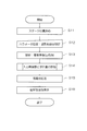
- FIG. 2 is a flowchart for explaining the procedure of the super-resolution reconstruction process.
- the super-resolution reconstruction process uses a plurality of images (image group having a positional deviation of one pixel or less) shifted from each other by a sub-pixel distance, and has a resolution higher than the resolution determined by the specifications of the X-ray detector 42. This is digital image processing for creating one high-resolution image (super-resolution image).
- the super-resolution reconstruction process includes the following three procedures.
- a plurality of images having a sub-pixel level displacement amount (an amount smaller than the size of one pixel of the X-ray detector 42) generated when the stage 43 is moved and returned to the original position (input) Image group)
- a step of calculating a displacement amount between each of the acquired input images and a reference image before moving the stage and thirdly, a displacement between each input image and the input image.
- the control unit 30 performs positioning of the stage 43 for determining the first X-ray imaging position (step S11).
- the control unit 30 that has received an input from the operation unit 46 creates a drive signal for the stage 43 by the movement control unit 35, and outputs the drive signal. It transmits to the stage moving mechanism 44.
- the stage 43 on which the workpiece W is placed is moved to the designated position by driving the stage moving mechanism 44, the position of the workpiece W in the casing 40 is determined. Thereby, the distance between the X-ray tube and the workpiece W and the distance between the workpiece W and the X-ray detector 42 are determined, and the geometric enlargement ratio is determined.
- step S12 the number of shots is set (step S12).
- M is an integer of 2 or more.
- the image processing unit 34 obtains a reference image (I when calculating an image shift amount caused by repeated positioning error of the stage 43 described later.
- the first input image that becomes 0 ) is acquired (step S13).
- an input image group and shift amount acquisition step for super-resolution reconstruction processing is executed (step S14).
- FIG. 3 is a flowchart for explaining a procedure for acquiring an input image group and a shift amount according to the first embodiment.
- Step S14 corresponds to the first and second processes of the super-resolution reconstruction process described above, and is a process of acquiring an input image group by executing continuous X-ray imaging for the super-resolution reconstruction process. .
- the image processing unit 34 displays the input image (I i ) and the shift amount ( ⁇ u i , ⁇ v i ) used for the reconstruction process (step S15) described later from the first sheet to M sheets. Get to the eye sequentially.
- i is an integer greater than or equal to zero
- the control unit 30 determines whether or not the number of input images i to be acquired is a value equal to or smaller than the number of captured images M (step S22). If the number of input images i is greater than the number of captured images M, image processing is performed. The operation of acquiring the input image group and the shift amount by the unit 34 is terminated. On the other hand, if the number of input images i is less than or equal to M, the following steps for acquiring the input image (I i ) and the amount of deviation ( ⁇ u i , ⁇ v i ) are executed. Note that the unit of the shift amount ( ⁇ u i , ⁇ v i ) may be a pixel or a unit of length such as mm (millimeter).
- the control unit 30 moves the stage 43 to an arbitrary position by (+ x, + y) by the action of the movement control unit 35 (step S23), and then moves the stage 43 by ( ⁇ x, ⁇ y). (Step S24).
- the stage 43 moves in accordance with a signal given from the movement control unit 35 to the motor of the stage moving mechanism 44.
- the operation of the X-ray control unit 36 performs X-ray imaging at the position of the stage 43 at that time, and the image processing unit 34 acquires an input image (I i ) (step S25).
- x and y representing the driving amount represent the number of pulses for driving the stage 43.
- + x means that the X axis of the stage 43 is driven by x pulses in the positive direction, and -x means that only x pulses are driven in the negative direction.
- + y means that the Y axis of the stage 43 is driven by y pulses in the positive direction, and -y is that y pulses are driven in the negative direction.
- the stage 43 When the stage 43 is moved by ⁇ x from a state where it is moved by + x from a certain position, it returns to the original position in terms of numbers.
- due to positioning errors caused by mechanical movement errors of the stage 43 even if a command to move to another position is given and then the opposite command is given, it will not return to the exact same position as the original position. It moves to a slightly different position every time.
- the variation in the moving position is a random result close to a normal distribution.
- this operation is repeated with two orthogonal axes such as the X direction and the Y direction, the moving positions are randomly distributed on the two-dimensional plane.
- the stage 43 is moved by (+ x, + y) to an arbitrary position perpendicular to the optical axis of the X-ray from the X-ray source 41 toward the X-ray detector 42, and then the stage 43 is moved therefrom.
- a random variation repetition positioning error
- the specific aspect of the repeated positioning is not only the driving that directly reciprocates between the two positions as described above, but the first position after the third point through two or more positions. You may employ
- the values of x and y are not particularly limited, but about 2 to 5 pulses are appropriate.
- the control unit 30 uses a registration method between the images by the image processing unit 34 to register the reference image (I 0 ) and the input image (I i ). ( ⁇ u i , ⁇ v i ) is obtained (step S26).
- the registration in step S26 measures how much the position when the input image (I i ) is photographed is translated from the position when the reference image (I 0 ) is photographed.
- a technique for example, a technique for obtaining a normalized cross-correlation between images can be used.
- step S27 When the shift amounts ( ⁇ u i , ⁇ v i ) are obtained, whether or not the shift amount ⁇ u i in the X direction is smaller than one pixel (pixel) of the X-ray detector 42, and the shift amount ⁇ v i in the Y direction is the X-ray. It is determined whether or not it is smaller than one pixel (pixel) of the detector 42 (step S27), and when both the deviation amount ⁇ u i in the X direction and the deviation amount ⁇ v i in the Y direction are smaller than one pixel, Returning to step S21 to acquire the next input image, 1 is added to i to update the value of i.
- step S28 the input image (I i ) is once discarded (step S28), and the process returns to step S23 to acquire the input image (I i ) and its deviation amount ( ⁇ u i , ⁇ v i ) again.
- the processes up to step S27 are repeated.
- Step S21 If the shift amount between images is smaller than one pixel in both the X direction and the Y direction, the image having the shift amount is stored as an input image having a sub pixel level shift amount, and the next input image Then, the process returns to step S21 to obtain the grazing amount. Steps S21 to S28 are repeated until the first to Mth input images (I i ) and their shift amounts ( ⁇ u i , ⁇ v i ) are acquired, and in step S22, the number of input images to be acquired from now on When i exceeds the number M of shots set in step S12, the input image group and shift amount acquisition step (step S14) ends.
- the image processing unit 34 performs a reconstruction process (step S15) using the input image group having the shift amount of the sub-pixel level.
- This reconstruction process is realized by a program of the image processing unit 34 in the control unit 30.
- an iterative backprojection method (IBP method) used for reconstruction of an X-ray CT image is used.
- IBP method iterative backprojection method
- N ⁇ N X-ray images having a positional shift of 1 / N pixels in the vertical and horizontal directions as input images.
- a plurality of images translated in parallel with each other are acquired using repeated positioning errors when the stage 43 is repeatedly moved to an arbitrary position. Is not exactly 1 / N pixel in the vertical and horizontal directions, but super-resolution reconstruction processing is possible if the positional shift amount can be accurately measured in the shift amount acquisition step (step S14). is there. Further, since it is not necessary to make the movement accuracy of the stage 43 of the stage moving mechanism 44 movable at the sub-pixel level, it is not necessary to employ parts with high positioning accuracy, and it is possible to prevent the apparatus from becoming expensive. Is possible.
- the super-resolution image created by the reconstruction process (step S15) is displayed on the display unit 45 by the action of the display control unit 33 and stored in the storage device 38. Thereby, the user can obtain an image having a higher resolution than the resolution determined by the pixel of the X-ray detector 42 and the geometric magnification.
- FIG. 4 is a flowchart for describing an acquisition procedure of an input image group and a shift amount according to the second embodiment.
- FIG. 5 and FIG. 6 are schematic diagrams for explaining a cut-out process of an image acquired as an input image group.
- an image (I ′ 0 ) is created from the reference image (I 0 ) acquired in step S13.
- Image (I'0) is the second reference image extracted from the reference image (I 0), in this embodiment, the image (I'0) and the input image of the same size (I'i) the deviation
- the amount ( ⁇ u ′ i , ⁇ v ′ i ) is acquired as an input image group for the super-resolution reconstruction process and its positional deviation amount.
- the control unit 30 uses the image processing unit 34 to set a distance w in the X direction and a distance h in the Y direction from a predetermined position (s, t) on the reference image (I 0 ).
- a rectangular image is cut out, and an image (I ′ 0 ) is created from the reference image (I 0 ) (step S31).
- the unit of s, t, w, h may be a pixel, or may be a unit of length such as mm (millimeter).
- the image (I ′ 0 ) is cut out when the user operates the mouse of the operation unit 46 to select a rectangular range from an arbitrary click position on the reference image (I 0 ) displayed on the display unit 45.
- s, t, w, and h may be set in advance by the user operating the keyboard of the operation unit 46 and inputting numerical values.
- the control unit 30 determines whether or not the number i of input images to be acquired by the image processing unit 34 is equal to or less than the number M of captured images set in step S13 (step S33), and the number i of input images is M. If the value is larger, the acquisition of the input image group and the shift amount is terminated.
- the following steps for acquiring the input image (I ′ i ) and the shift amount ( ⁇ u ′ i , ⁇ v ′ i ) are executed.
- the control unit 30 moves the stage 43 to the position (+ x, + y) by the action of the movement control unit 35 (step S34), and then moves the stage 43 to the position ( ⁇ x, ⁇ y) (step S35). Thereafter, X-ray imaging is performed at the position of the stage 43 at that time, and an image (I i ) is acquired (step S36).
- the image processing unit 34 functions to shift the amount ( ⁇ u i ) between the reference image (I 0 ) and the image (I i ) using the registration technique. , ⁇ v i ) (step S37). Thereafter, the deviation amount ( ⁇ u i, ⁇ v i) the integer part (u i, v i) and fraction part ( ⁇ u' i, ⁇ v' i) is separated into a (step S38).
- step S38 when the shift amount ( ⁇ u i , ⁇ v i ) and the unit of s, t, w, h are pixels, the integer part of the pixel unit separated from the shift amount ( ⁇ u i , ⁇ v i ) as it is The decimal part becomes an integer part (u i , v i ) and a decimal part ( ⁇ u ′ i , ⁇ v ′ i ).
- the shift amount ( ⁇ u i , ⁇ v i ) and the unit of s, t, w, h are units of length such as mm or ⁇ m (micrometer)
- the shift amount ( ⁇ u i , ⁇ v i ) is set.
- a value obtained by dividing the length of one pixel in the X direction and the Y direction is obtained, and the value is separated into an integer part and a decimal part, and an integer part (u i , v i ) and a decimal part ( ⁇ u ′) i , ⁇ v ′ i ).
- the decimal portion ( ⁇ u ′ i , ⁇ v ′ i ) is a sub-pixel level shift amount smaller than one pixel.
- the image processing unit 34 adds an integer part (u i , v i ) to the base point (s, t) when the image (I ′ 0 ) is previously cut out from the reference image (I 0 ). adding images (I i) on the (s + u i, t + v i) as base point, cut X-direction distance w, the rectangular image in the Y-direction distance h as an input image (I'i) (step S39). Then, the fractional part ( ⁇ u ′ i , ⁇ v ′ i ) is stored as a shift amount with respect to the input image (I ′ i ) after cutting (step S40).
- the input image (I ′ i ) is acquired as an input image having a sub-pixel level shift amount ( ⁇ u ′ i , ⁇ v ′ i ).
- the input image group and shift amount acquisition step (step S14) ends.
- the image processing unit 34 executes a reconstruction process (step S15) using the input image group having the shift amount of the sub-pixel level.
- the super-resolution image generated by the reconstruction process (step S15) is stored in the storage device 38 and displayed on the display unit 45 by the action of the display control unit 33. Thereby, the user can obtain an image having a higher resolution than the resolution determined by the pixel of the X-ray detector 42 and the geometric magnification.
- an image cut out from an X-ray image is used as the input image group in the next reconstruction process (step S15), and a deviation amount between the reference image (I 0 ) and the image (I i ) is used.
- ⁇ u i, ⁇ v i the integer part (u i, v i) and fraction part ( ⁇ u' i, ⁇ v' i) is separated into an integer part (u i, v i) is the input image (I'i ) Is reflected in the base point position on the image when cutting out.
- the shift amount ( ⁇ u i , ⁇ v i ) between the reference image (I 0 ) and the image (I i ).
- the X-ray imaging by discarding the reference image (I 0) image shift amount between the (I i) ( ⁇ u i, ⁇ v i) is not less than 1 pixel image (I i) Therefore, the shooting time may be long.
- the situation of redoing the X-ray does not occur, so that the time for acquiring the input image group and the shift amount does not become longer as compared with the first embodiment.
- the stage 43 is repeatedly moved in the direction (XY direction) perpendicular to the optical axis of the X-ray.
- a mechanical movement error is caused. May appear as a positional shift in the XY direction, so the moving direction of the stage 43 is not limited to the direction perpendicular to the optical axis of the X-ray.
- an example of acquiring an input image group having a sub-pixel level displacement amount for creating a super-resolution image using the repeated positioning error of the stage 43 has been shown.
- the component that is repeatedly positioned is not limited to the stage 43. That is, when the X-ray source 41 and the X-ray detector 42 constituting the X-ray imaging system are configured to be movable in a direction (XY direction) perpendicular to the optical axis of the X-ray by driving a motor, these Repeated positioning errors caused by repeated movement of the elements may be used.
- X-ray imaging is performed at randomly scattered positions on a two-dimensional plane using the repeated positioning error of the mechanical elements of the X-ray inspection apparatus, and an input image group necessary for super-resolution reconstruction is obtained. Therefore, it is not necessary to make the moving accuracy of the stage 43 of the stage moving mechanism 44 possible to move at the sub-pixel level. For this reason, it is possible to add a function of obtaining a super-resolution image without replacing the moving mechanism of the existing industrial X-ray inspection apparatus with a part having high positioning accuracy, and to suppress the increase in the cost of the apparatus. Is possible.
- the present invention can also be applied to an X-ray CT imaging apparatus.
- an X-ray CT imaging apparatus by applying the method of the present invention at the stage of acquiring X-ray fluoroscopic data before reconstructing a tomographic image, an image having a high resolution can be obtained even in a finally obtained tomographic image. Can do. That is, in order to change the relative positional relationship between the X-ray source, the X-ray detector, and the subject, any one of the X-ray source, the X-ray detector, and the table on which the subject is placed is moved by the moving mechanism. If it is the structure which carries out, it is possible to apply this invention and to obtain a super-resolution image.
Landscapes
- Health & Medical Sciences (AREA)
- Theoretical Computer Science (AREA)
- Engineering & Computer Science (AREA)
- General Physics & Mathematics (AREA)
- Physics & Mathematics (AREA)
- Radiology & Medical Imaging (AREA)
- Pulmonology (AREA)
- Life Sciences & Earth Sciences (AREA)
- Chemical & Material Sciences (AREA)
- Analytical Chemistry (AREA)
- Biochemistry (AREA)
- General Health & Medical Sciences (AREA)
- Nuclear Medicine, Radiotherapy & Molecular Imaging (AREA)
- Immunology (AREA)
- Pathology (AREA)
- Analysing Materials By The Use Of Radiation (AREA)
Abstract
Description
31 メモリ
32 演算装置
33 表示制御部
34 画像処理部
35 移動制御部
36 X線制御部
38 記憶装置
39 バス
40 ケーシング
41 X線源
42 X線検出器
43 ステージ
44 ステージ移動機構
45 表示部
46 操作部
Claims (4)
- X線源と、被検体を載置するテーブルと、前記X線源から照射され前記被検体を透過したX線を検出するX線検出器と、X線撮影により取得した画像を表示する表示部を備えたX線検査装置において、
前記X線源、前記X線検出器、または、前記テーブルを移動させることにより前記X線源と前記X線検出器と前記被検体との相対的位置関係を変更する移動機構と、
前記移動機構を制御する移動制御部と、前記X線源を制御するX線制御部と、前記X線検出器の出力を取り込んで前記被検体のX線画像を構築する画像処理部と、前記画像処理部により得られた画像を前記表示部に表示する表示制御部と、を有する制御部と、を備え、
前記画像処理部は、
前記X線源、前記X線検出器、前記テーブルのいずれか1つを、最初のX線画像を取得したときのX線撮影位置と任意の位置との間で往復移動させる位置決めを行った後に、X線撮影を実行する動作を繰り返して複数のX線画像を取得し、
前記位置決めを繰り返し行ったときの繰り返し位置決め誤差を利用して、前記複数のX線画像から互いにサブピクセルレベルの位置ずれ量を持つ画像を超解像再構成処理のための入力画像群として取得し、
前記入力画像群に対して超解像再構成処理を実行することにより超解像画像を生成することを特徴とするX線検査装置。 - 請求項1に記載のX線検査装置において、
前記画像処理部は、
画像間の位置合わせ手法を利用して、前記複数のX線画像の各々の前記位置ずれ量を求め、
前記複数のX線画像のうち前記位置ずれ量が前記X線検出器の1画素より小さい画像を、その位置ずれ量とともに前記入力画像群として取得するX線検査装置。 - 請求項1に記載のX線検査装置において、
前記画像処理部は、
前記最初のX線画像上の所定の位置を基点として切り出した第2の基準画像を作成し、
画像間の位置合わせ手法を利用して、前記複数のX線画像の各々の前記位置ずれ量を求め、
前記位置ずれ量を整数部分と小数部分に分離し、
前記複数のX線画像の各々の画像上の前記所定の位置に前記位置ずれ量の整数部分を加えた位置を基点として、前記第2の基準画像と同サイズの画像を切り出し、切り出した画像を前記位置ずれ量の小数部分とともに前記入力画像群として取得するX線検査装置。 - 請求項1から請求項3のいずれかに記載のX線検査装置において、
前記移動機構は、前記テーブルに接続され、前記X線源と前記X線検出器からなるX線撮影系に対して前記テーブルの位置を移動させるX線検査装置。
Priority Applications (6)
| Application Number | Priority Date | Filing Date | Title |
|---|---|---|---|
| JP2020520883A JP6973637B2 (ja) | 2018-05-21 | 2018-05-21 | X線検査装置 |
| US17/052,527 US11268917B2 (en) | 2018-05-21 | 2018-05-21 | X-ray inspection apparatus |
| PCT/JP2018/019543 WO2019224888A1 (ja) | 2018-05-21 | 2018-05-21 | X線検査装置 |
| KR1020207033474A KR102355657B1 (ko) | 2018-05-21 | 2018-05-21 | X선 검사 장치 |
| CN201880093071.7A CN112074727A (zh) | 2018-05-21 | 2018-05-21 | X射线检查装置 |
| EP18919604.1A EP3798623A4 (en) | 2018-05-21 | 2018-05-21 | X-RAY INSPECTION DEVICE |
Applications Claiming Priority (1)
| Application Number | Priority Date | Filing Date | Title |
|---|---|---|---|
| PCT/JP2018/019543 WO2019224888A1 (ja) | 2018-05-21 | 2018-05-21 | X線検査装置 |
Publications (1)
| Publication Number | Publication Date |
|---|---|
| WO2019224888A1 true WO2019224888A1 (ja) | 2019-11-28 |
Family
ID=68616868
Family Applications (1)
| Application Number | Title | Priority Date | Filing Date |
|---|---|---|---|
| PCT/JP2018/019543 Ceased WO2019224888A1 (ja) | 2018-05-21 | 2018-05-21 | X線検査装置 |
Country Status (6)
| Country | Link |
|---|---|
| US (1) | US11268917B2 (ja) |
| EP (1) | EP3798623A4 (ja) |
| JP (1) | JP6973637B2 (ja) |
| KR (1) | KR102355657B1 (ja) |
| CN (1) | CN112074727A (ja) |
| WO (1) | WO2019224888A1 (ja) |
Families Citing this family (3)
| Publication number | Priority date | Publication date | Assignee | Title |
|---|---|---|---|---|
| JP7698996B2 (ja) * | 2021-06-30 | 2025-06-26 | キヤノンメディカルシステムズ株式会社 | X線診断装置、x線診断方法、およびプログラム |
| EP4429554B1 (en) * | 2021-11-10 | 2025-12-31 | Carestream Health, Inc. | DEVICE FOR ENHANCING DIGITAL X-RAY IMAGING |
| CN114494416A (zh) * | 2021-12-31 | 2022-05-13 | 深圳市瑞图生物技术有限公司 | 载物平台的重复定位精度测量方法、系统及存储介质 |
Citations (6)
| Publication number | Priority date | Publication date | Assignee | Title |
|---|---|---|---|---|
| JP2002243663A (ja) * | 2001-02-09 | 2002-08-28 | Shimadzu Corp | X線透視装置 |
| JP2005134213A (ja) * | 2003-10-29 | 2005-05-26 | Sony Corp | X線断層撮像方法及び装置 |
| JP2005326260A (ja) * | 2004-05-14 | 2005-11-24 | Sony Corp | X線撮像装置 |
| JP2006317249A (ja) | 2005-05-12 | 2006-11-24 | Shimadzu Corp | X線撮影装置 |
| JP2016517961A (ja) * | 2013-04-12 | 2016-06-20 | イリノイ トゥール ワークス インコーポレイティド | 高解像度コンピュータートモグラフィー |
| JP2017223468A (ja) * | 2016-06-13 | 2017-12-21 | オムロン株式会社 | X線検査装置およびx線検査方法 |
Family Cites Families (7)
| Publication number | Priority date | Publication date | Assignee | Title |
|---|---|---|---|---|
| JP2621416B2 (ja) * | 1988-09-22 | 1997-06-18 | 松下電器産業株式会社 | 移動量の測定用プレート |
| US6459823B2 (en) * | 1998-10-28 | 2002-10-01 | Hewlett-Packard Company | Apparatus and method of increasing scanner resolution |
| JP4519434B2 (ja) | 2003-09-24 | 2010-08-04 | 株式会社東芝 | 超解像処理装置及び医用画像診断装置 |
| JP2013015426A (ja) * | 2011-07-05 | 2013-01-24 | Shimadzu Corp | 放射線ct装置 |
| JP6015404B2 (ja) * | 2012-12-11 | 2016-10-26 | 株式会社島津製作所 | 放射線検査装置 |
| JP6246936B2 (ja) * | 2014-07-28 | 2017-12-13 | 株式会社日立製作所 | X線撮像装置および画像再構成方法 |
| JP6624369B2 (ja) | 2015-01-23 | 2019-12-25 | パナソニックIpマネジメント株式会社 | 画像処理装置、画像処理方法、画像表示装置およびコンピュータプログラム |
-
2018
- 2018-05-21 EP EP18919604.1A patent/EP3798623A4/en not_active Withdrawn
- 2018-05-21 KR KR1020207033474A patent/KR102355657B1/ko active Active
- 2018-05-21 WO PCT/JP2018/019543 patent/WO2019224888A1/ja not_active Ceased
- 2018-05-21 US US17/052,527 patent/US11268917B2/en active Active
- 2018-05-21 CN CN201880093071.7A patent/CN112074727A/zh active Pending
- 2018-05-21 JP JP2020520883A patent/JP6973637B2/ja active Active
Patent Citations (6)
| Publication number | Priority date | Publication date | Assignee | Title |
|---|---|---|---|---|
| JP2002243663A (ja) * | 2001-02-09 | 2002-08-28 | Shimadzu Corp | X線透視装置 |
| JP2005134213A (ja) * | 2003-10-29 | 2005-05-26 | Sony Corp | X線断層撮像方法及び装置 |
| JP2005326260A (ja) * | 2004-05-14 | 2005-11-24 | Sony Corp | X線撮像装置 |
| JP2006317249A (ja) | 2005-05-12 | 2006-11-24 | Shimadzu Corp | X線撮影装置 |
| JP2016517961A (ja) * | 2013-04-12 | 2016-06-20 | イリノイ トゥール ワークス インコーポレイティド | 高解像度コンピュータートモグラフィー |
| JP2017223468A (ja) * | 2016-06-13 | 2017-12-21 | オムロン株式会社 | X線検査装置およびx線検査方法 |
Non-Patent Citations (1)
| Title |
|---|
| See also references of EP3798623A4 |
Also Published As
| Publication number | Publication date |
|---|---|
| JP6973637B2 (ja) | 2021-12-01 |
| JPWO2019224888A1 (ja) | 2021-03-11 |
| CN112074727A (zh) | 2020-12-11 |
| EP3798623A1 (en) | 2021-03-31 |
| US20210239626A1 (en) | 2021-08-05 |
| US11268917B2 (en) | 2022-03-08 |
| EP3798623A4 (en) | 2021-06-09 |
| KR20210002591A (ko) | 2021-01-08 |
| KR102355657B1 (ko) | 2022-02-08 |
Similar Documents
| Publication | Publication Date | Title |
|---|---|---|
| US10859513B2 (en) | Oblique CT apparatus | |
| US11189012B2 (en) | Arrangement having a coordinate measuring machine or microscope | |
| DE102014206309A1 (de) | System und Verfahren zum Erhalten von Bildern mit Versatz zur Verwendung für verbesserte Kantenauflösung | |
| DE102010000075A1 (de) | Messvorrichtung | |
| JP6973637B2 (ja) | X線検査装置 | |
| DE102017211328A1 (de) | Bildmessgerät | |
| CN108240998A (zh) | 计算机断层扫描 | |
| JP6153105B2 (ja) | Ct装置 | |
| CN110868932B (zh) | 放射线相位差摄影装置 | |
| JP6983704B2 (ja) | 計測用x線ctの測定計画生成方法及び装置 | |
| EP3911236B1 (en) | Estimation of full-field scattering for dax imaging | |
| JP2020186913A (ja) | X線ct装置、及びct画像再構成方法 | |
| US20210172885A1 (en) | X-ray imaging device | |
| KR101904788B1 (ko) | 컴퓨터 단층 촬영 장치 | |
| EP3605073A2 (en) | X-rax transmission inspection apparatus and x-ray transmission inspection method | |
| JP4818695B2 (ja) | 放射線画像撮像条件の補正装置 | |
| KR102286358B1 (ko) | X선 촬상 장치 | |
| KR100423967B1 (ko) | 엑스선 촬영장치의 3차원 영상 구현 방법 | |
| JP6185697B2 (ja) | X線分析装置 | |
| JP2022010384A (ja) | X線ct装置 | |
| JP2004219224A (ja) | コンピュータ断層撮影装置 | |
| JP2025001323A (ja) | X線ct装置及びx線ct装置の制御方法 | |
| EP4673732A1 (en) | Guidance for geometrical and optical magnification in x-ray microscope | |
| JPWO2020044581A1 (ja) | X線位相イメージング装置 | |
| JP2009128063A (ja) | 3次元形状測定装置及び該動作方法 |
Legal Events
| Date | Code | Title | Description |
|---|---|---|---|
| 121 | Ep: the epo has been informed by wipo that ep was designated in this application |
Ref document number: 18919604 Country of ref document: EP Kind code of ref document: A1 |
|
| ENP | Entry into the national phase |
Ref document number: 2020520883 Country of ref document: JP Kind code of ref document: A |
|
| ENP | Entry into the national phase |
Ref document number: 20207033474 Country of ref document: KR Kind code of ref document: A |
|
| NENP | Non-entry into the national phase |
Ref country code: DE |
|
| ENP | Entry into the national phase |
Ref document number: 2018919604 Country of ref document: EP Effective date: 20201221 |