WO2019225136A1 - 画像処理装置、表示装置、画像処理方法 - Google Patents
画像処理装置、表示装置、画像処理方法 Download PDFInfo
- Publication number
- WO2019225136A1 WO2019225136A1 PCT/JP2019/012181 JP2019012181W WO2019225136A1 WO 2019225136 A1 WO2019225136 A1 WO 2019225136A1 JP 2019012181 W JP2019012181 W JP 2019012181W WO 2019225136 A1 WO2019225136 A1 WO 2019225136A1
- Authority
- WO
- WIPO (PCT)
- Prior art keywords
- liquid crystal
- crystal cell
- image
- filter
- illuminance
- Prior art date
- Legal status (The legal status is an assumption and is not a legal conclusion. Google has not performed a legal analysis and makes no representation as to the accuracy of the status listed.)
- Ceased
Links
Images


Classifications
-
- G—PHYSICS
- G09—EDUCATION; CRYPTOGRAPHY; DISPLAY; ADVERTISING; SEALS
- G09G—ARRANGEMENTS OR CIRCUITS FOR CONTROL OF INDICATING DEVICES USING STATIC MEANS TO PRESENT VARIABLE INFORMATION
- G09G3/00—Control arrangements or circuits, of interest only in connection with visual indicators other than cathode-ray tubes
- G09G3/20—Control arrangements or circuits, of interest only in connection with visual indicators other than cathode-ray tubes for presentation of an assembly of a number of characters, e.g. a page, by composing the assembly by combination of individual elements arranged in a matrix no fixed position being assigned to or needed to be assigned to the individual characters or partial characters
- G09G3/34—Control arrangements or circuits, of interest only in connection with visual indicators other than cathode-ray tubes for presentation of an assembly of a number of characters, e.g. a page, by composing the assembly by combination of individual elements arranged in a matrix no fixed position being assigned to or needed to be assigned to the individual characters or partial characters by control of light from an independent source
- G09G3/36—Control arrangements or circuits, of interest only in connection with visual indicators other than cathode-ray tubes for presentation of an assembly of a number of characters, e.g. a page, by composing the assembly by combination of individual elements arranged in a matrix no fixed position being assigned to or needed to be assigned to the individual characters or partial characters by control of light from an independent source using liquid crystals
-
- G—PHYSICS
- G02—OPTICS
- G02F—OPTICAL DEVICES OR ARRANGEMENTS FOR THE CONTROL OF LIGHT BY MODIFICATION OF THE OPTICAL PROPERTIES OF THE MEDIA OF THE ELEMENTS INVOLVED THEREIN; NON-LINEAR OPTICS; FREQUENCY-CHANGING OF LIGHT; OPTICAL LOGIC ELEMENTS; OPTICAL ANALOGUE/DIGITAL CONVERTERS
- G02F1/00—Devices or arrangements for the control of the intensity, colour, phase, polarisation or direction of light arriving from an independent light source, e.g. switching, gating or modulating; Non-linear optics
- G02F1/01—Devices or arrangements for the control of the intensity, colour, phase, polarisation or direction of light arriving from an independent light source, e.g. switching, gating or modulating; Non-linear optics for the control of the intensity, phase, polarisation or colour
- G02F1/13—Devices or arrangements for the control of the intensity, colour, phase, polarisation or direction of light arriving from an independent light source, e.g. switching, gating or modulating; Non-linear optics for the control of the intensity, phase, polarisation or colour based on liquid crystals, e.g. single liquid crystal display cells
- G02F1/133—Constructional arrangements; Operation of liquid crystal cells; Circuit arrangements
- G02F1/1333—Constructional arrangements; Manufacturing methods
- G02F1/1347—Arrangement of liquid crystal layers or cells in which the final condition of one light beam is achieved by the addition of the effects of two or more layers or cells
-
- G—PHYSICS
- G09—EDUCATION; CRYPTOGRAPHY; DISPLAY; ADVERTISING; SEALS
- G09G—ARRANGEMENTS OR CIRCUITS FOR CONTROL OF INDICATING DEVICES USING STATIC MEANS TO PRESENT VARIABLE INFORMATION
- G09G2300/00—Aspects of the constitution of display devices
- G09G2300/02—Composition of display devices
- G09G2300/023—Display panel composed of stacked panels
-
- G—PHYSICS
- G09—EDUCATION; CRYPTOGRAPHY; DISPLAY; ADVERTISING; SEALS
- G09G—ARRANGEMENTS OR CIRCUITS FOR CONTROL OF INDICATING DEVICES USING STATIC MEANS TO PRESENT VARIABLE INFORMATION
- G09G2320/00—Control of display operating conditions
- G09G2320/02—Improving the quality of display appearance
- G09G2320/0233—Improving the luminance or brightness uniformity across the screen
-
- G—PHYSICS
- G09—EDUCATION; CRYPTOGRAPHY; DISPLAY; ADVERTISING; SEALS
- G09G—ARRANGEMENTS OR CIRCUITS FOR CONTROL OF INDICATING DEVICES USING STATIC MEANS TO PRESENT VARIABLE INFORMATION
- G09G2320/00—Control of display operating conditions
- G09G2320/02—Improving the quality of display appearance
- G09G2320/0238—Improving the black level
-
- G—PHYSICS
- G09—EDUCATION; CRYPTOGRAPHY; DISPLAY; ADVERTISING; SEALS
- G09G—ARRANGEMENTS OR CIRCUITS FOR CONTROL OF INDICATING DEVICES USING STATIC MEANS TO PRESENT VARIABLE INFORMATION
- G09G2320/00—Control of display operating conditions
- G09G2320/02—Improving the quality of display appearance
- G09G2320/0271—Adjustment of the gradation levels within the range of the gradation scale, e.g. by redistribution or clipping
-
- G—PHYSICS
- G09—EDUCATION; CRYPTOGRAPHY; DISPLAY; ADVERTISING; SEALS
- G09G—ARRANGEMENTS OR CIRCUITS FOR CONTROL OF INDICATING DEVICES USING STATIC MEANS TO PRESENT VARIABLE INFORMATION
- G09G2320/00—Control of display operating conditions
- G09G2320/06—Adjustment of display parameters
- G09G2320/0626—Adjustment of display parameters for control of overall brightness
- G09G2320/0646—Modulation of illumination source brightness and image signal correlated to each other
-
- G—PHYSICS
- G09—EDUCATION; CRYPTOGRAPHY; DISPLAY; ADVERTISING; SEALS
- G09G—ARRANGEMENTS OR CIRCUITS FOR CONTROL OF INDICATING DEVICES USING STATIC MEANS TO PRESENT VARIABLE INFORMATION
- G09G2330/00—Aspects of power supply; Aspects of display protection and defect management
- G09G2330/04—Display protection
- G09G2330/045—Protection against panel overheating
-
- G—PHYSICS
- G09—EDUCATION; CRYPTOGRAPHY; DISPLAY; ADVERTISING; SEALS
- G09G—ARRANGEMENTS OR CIRCUITS FOR CONTROL OF INDICATING DEVICES USING STATIC MEANS TO PRESENT VARIABLE INFORMATION
- G09G2340/00—Aspects of display data processing
-
- G—PHYSICS
- G09—EDUCATION; CRYPTOGRAPHY; DISPLAY; ADVERTISING; SEALS
- G09G—ARRANGEMENTS OR CIRCUITS FOR CONTROL OF INDICATING DEVICES USING STATIC MEANS TO PRESENT VARIABLE INFORMATION
- G09G2360/00—Aspects of the architecture of display systems
- G09G2360/14—Detecting light within display terminals, e.g. using a single or a plurality of photosensors
- G09G2360/144—Detecting light within display terminals, e.g. using a single or a plurality of photosensors the light being ambient light
Definitions
- the present technology relates to an image processing device, a display device, and an image processing method, and more particularly to processing of an image signal for a display panel in which a display image is generated by light passing through a rear liquid crystal cell and a front liquid crystal cell.
- a high contrast ratio can be realized by controlling gradation with a rear liquid crystal cell, but the luminance viewing angle tends to be narrower than that of a single liquid crystal cell.
- a technique for improving this there is a case where an image is blurred using a spatial filter in image generation of a rear liquid crystal cell close to a backlight.
- the visual sensitivity (how to perceive brightness) of the human eye changes depending on the ambient illuminance of the display device even if the display (brightness) is constant.
- the ambient illuminance is bright, the display device looks relatively dark, so the viewing angle feels narrower.
- An image processing apparatus provides a rear image signal for the rear liquid crystal cell and a front image for the front liquid crystal cell as an image signal for a display panel in which a display image is generated by light that has passed through the rear liquid crystal cell and the front liquid crystal cell.
- An image processing unit that generates an image signal, a filter control unit that controls a spatial filter process applied to a rear image signal in the image processing unit based on a detection value of an illuminance sensor that detects illuminance in the vicinity of the display panel; Is provided.
- An image signal to be processed by this image processing apparatus is an image signal used in a liquid crystal display panel of a dual liquid crystal cell type.
- the image processing apparatus performs image signal processing on each of a front liquid crystal cell and a rear liquid crystal cell of a dual liquid crystal cell type liquid crystal display panel.
- a spatial filter process may be performed on the rear image signal.
- the spatial filter process is controlled according to the illuminance.
- the image processing unit performs the spatial filter processing on the rear image signal to widen the transmission pixel range of the image in the rear liquid crystal cell more than the image of the front liquid crystal cell.
- spatial filter processing is performed so as to blur the rear image.
- a low-pass filter for the rear image signal is used so that the image of the front liquid crystal cell by the front image signal is widened so that the range of pixels transmitted on the rear liquid crystal cell side is widened. Apply processing.
- the filter control unit variably controls a parameter that changes a filter characteristic in the spatial filter processing based on a detection value of the illuminance sensor. That is, when the spatial filter processing is applied to the rear image signal so that the transmissive pixel range of the rear liquid crystal cell is wider than the transmissive pixel range of the front liquid crystal cell, the shape of the passing waveform (the shape of the gradation value spread) Is variable.
- the parameter may be a filter pass width of the rear image signal.
- the filter pass width is the width of the range of the rear image signal that becomes gentle by the spatial filter processing (the width including the tail portion of the signal by the low pass processing). That is, it corresponds to the range of transmission pixels (blurring range) when the range of transmission pixels of the rear liquid crystal cell by the rear image signal is wider than the range of transmission pixels of the front liquid crystal cell.
- the filter passing width is varied according to the illuminance.
- the parameter may be a peak width of the rear image signal.
- the peak width is the width of a range that is the original gradation value (peak value) of the pixel of the rear image signal that becomes gentle by the spatial filter processing.
- the peak width is varied according to the illuminance.
- the parameter may be a peak value of the rear image signal.
- the peak value is the gradation value of the peak of the rear image signal that becomes gentle by the spatial filter processing. Usually, this is the original gradation value of the corresponding pixel, but this peak value is made variable according to the illuminance.
- the filter control unit detects, as the detection value of the illuminance sensor, the lower the illuminance, the narrower the image blur range of the rear liquid crystal cell, and the higher the illuminance, It is conceivable to control the spatial filter processing so that the image blur range of the cell is widened.
- the image blur range is controlled by controlling the filter shape of the rear image signal, for example.
- the filter control unit detects, as the detection value of the illuminance sensor, the lower the illuminance, the smaller the light transmission amount of the rear liquid crystal cell, and the higher the illuminance, It is conceivable to control the spatial filter processing so that the amount of light transmitted through the liquid crystal cell increases.
- the light transmission amount is controlled by controlling the peak value of the gradation of the rear image signal, for example.
- the filter control unit controls the spatial filter processing so as to change the filter characteristics in a stepwise manner when an illuminance change is detected based on a detection value of the illuminance sensor. It is possible. That is, when a change in illuminance is detected, the filter shape corresponding to the new illuminance is not changed at once, but gradually changed.
- the filter control unit determines the illuminance when the detection value of the illuminance sensor becomes a value exceeding a predetermined change width from the value when the previous filter control is performed. It is conceivable to perform variable control of the spatial filter process according to the change. That is, the variable control of the spatial filter processing is not performed unnecessarily due to a slight change in illuminance.
- a display device includes a display panel that generates a display image by light that has passed through a rear liquid crystal cell and a front liquid crystal cell, an illuminance sensor that detects illuminance in the vicinity of the display panel, and the above-described image processing device. .
- a display device for example, a light source unit, a rear liquid crystal cell, a diffusion layer, and a front liquid crystal cell are arranged in this order to constitute a so-called dual liquid crystal cell type liquid crystal display panel. Spatial filter control corresponding to the illuminance is performed on the rear image signal for the dual liquid crystal cell type liquid crystal display panel.
- an image processing procedure and a filter control procedure are performed as processing performed by the image processing unit and the filter control unit in the image processing apparatus.
- the spatial filter processing that blurs the image of the rear liquid crystal cell in accordance with the ambient environment illuminance it is possible to realize image quality improvement with reduced image loss and flare (black floating).
- the effects described here are not necessarily limited, and may be any of the effects described in the present disclosure.
- Configuration of display device> ⁇ 2.
- Configuration of Dual Cell Image Processing Unit> ⁇ 3.
- Spatial Filter Control in Embodiment> ⁇ 4.
- Processing of First Embodiment> ⁇ 5.
- Processing of Second Embodiment> ⁇ 6.
- Summary and Modification> For the sake of explanation, the three primary colors red, green, and blue are denoted by R, G, and B, respectively, in alphabets.
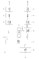
- FIG. 1 shows a configuration of a display device 90 according to the embodiment.
- the display device 90 includes the liquid crystal display panel 1, the image processing device 10, the front liquid crystal cell driving unit 20, and the rear liquid crystal cell driving unit 30.
- the liquid crystal display panel 1 is a dual cell type liquid crystal display panel, and includes a front liquid crystal cell 2, a diffusion layer 4, a rear liquid crystal cell 3, and a backlight 5.
- the rear liquid crystal cell 3, the diffusion layer 4, and the front liquid crystal cell 2 are arranged on the front side of the backlight 5 so as to overlap in this order, and the viewer sees the image displayed from the front side of the front liquid crystal cell 2. It will be.
- Each of the front liquid crystal cell 2 and the rear liquid crystal cell 3 forms one liquid crystal display panel.
- the entire dual liquid crystal cell type display panel is referred to as a liquid crystal display panel 1.
- the image processing apparatus 10 performs signal processing for display on the liquid crystal display panel 1 on the image signal S1 input as a color image signal (for example, a signal in the UHD (Ultra High Definition) format).
- the image processing apparatus 10 includes a display image processing unit 11, a dual cell image processing unit 12, and a filter control unit 15.
- the display image processing unit 11 performs necessary decoding processing, luminance processing, color processing, resolution conversion, and the like on the input image signal S1, and supplies the processed image signal Sig_in to the dual cell image processing unit 12. .
- a color image signal indicating the gradation value of each color of R, G, and B is used.
- the dual cell image processing unit 12 performs processing corresponding to the dual cell type liquid crystal display panel 1. That is, the dual cell image processing unit 12 performs signal processing on the input image signal Sig_in, and generates an image signal for the front liquid crystal cell 2 (front image signal Sig_FR) and an image signal for the rear liquid crystal cell 3 (rear image signal Sig_RE). And output.
- the front image signal Sig_FR is a color image signal including R, G, and B gradation values.
- the rear image signal Sig_RE is a black and white (grayscale) image signal including a gradation value as a grayscale.
- the filter control unit 15 is configured by, for example, a microprocessor that performs arithmetic processing.
- the filter control unit 15 controls the spatial filter processing in the dual cell image processing unit 12.
- the dual cell image processing unit 12 performs a spatial filter process on the rear image signal Sig_RE so as to blur the image.
- the filter control unit 15 controls the filter characteristics of this spatial filter processing.
- the filter control unit 15 performs a process of specifying a parameter that defines, for example, a filter characteristic by the control signal FC.
- the filter control unit 15 performs such filter control based on the detection value of the illuminance sensor 40.
- the illuminance sensor 40 is mounted on, for example, the display device 90, detects the illuminance due to ambient environmental light, and supplies the detection signal to the filter control unit 15.
- the illuminance sensor 40 is provided with a detection window on the surface of a housing as the display device 90 and detects illuminance.
- the liquid crystal display panel 1 is arranged so as to detect the illuminance on the front side.
- the illuminance sensor 40 may be separate from the display device 90.
- the front image signal Sig_FR output from the image processing apparatus 10 is supplied to the front liquid crystal cell driving unit 20.
- the front liquid crystal cell driving unit 20 drives the front liquid crystal cell 2 based on the front image signal Sig_FR to execute color image display.
- the rear image signal Sig_RE output from the image processing apparatus 10 is supplied to the rear liquid crystal cell driving unit 30.
- the rear liquid crystal cell driving unit 30 drives the rear liquid crystal cell 3 based on the rear image signal Sig_RE to execute monochrome image display.
- the front liquid crystal cell driving unit 20 includes a display control unit 21, a vertical driving unit 22, and a horizontal driving unit 23, and drives the front liquid crystal cell 2 with these configurations.
- the display control unit 21 supplies a control signal to the vertical drive unit 22 based on the front image signal Sig_FR, and also responds to the horizontal drive unit 23 in accordance with the image signals (R, G, and B gradation values). Signal) and control signals are supplied and controlled so as to operate in synchronization with each other.
- the vertical drive unit 22 Based on the control signal supplied from the display control unit 21, the vertical drive unit 22 sequentially selects one horizontal line as a display drive target in the front liquid crystal cell 2.
- the horizontal drive unit 23 generates a pixel voltage for one horizontal line based on the image signal and the control signal supplied from the display control unit 21, and sub-pixels 26 (for one horizontal line selected by the vertical drive unit 22 ( 26R, 26G, 26B).
- each pixel 25 has three sub-pixels 26R, 26G, and 26B.
- the sub-pixel 26R has a red color filter
- the sub-pixel 26G has a green color filter
- the sub-pixel 26B has a blue color filter.
- a pixel voltage is supplied to each of the sub-pixels 26R, 26G, and 26B from the horizontal driving unit 23.
- the sub-pixels 26R, 26G, and 26B change the light transmittance according to the pixel voltage.
- the rear liquid crystal cell driving unit 30 includes a display control unit 31, a vertical driving unit 32, and a horizontal driving unit 33, and drives the rear liquid crystal cell 3 with these configurations.
- the display control unit 31 supplies a control signal to the vertical drive unit 32 based on the rear image signal Sig_RE, and also outputs an image signal to the horizontal drive unit 33 (a signal corresponding to a gradation value as a gray scale). And a control signal is supplied to control them so as to operate in synchronization with each other.
- the vertical drive unit 32 Based on the control signal supplied from the display control unit 31, the vertical drive unit 32 sequentially selects one horizontal line as a display drive target in the front liquid crystal cell 2.
- the horizontal driving unit 33 generates a pixel voltage for one horizontal line based on the image signal and the control signal supplied from the display control unit 31, and supplies the pixel voltage for one horizontal line selected by the vertical driving unit 32. To supply.
- the rear liquid crystal cell 3 has a plurality of pixels 35 arranged in a matrix. Each pixel 35 has three sub-pixels 36. Each sub-pixel 36 does not have a color filter. That is, each sub pixel 26R, 26G, 26B in the front liquid crystal cell 2 has a color filter of a corresponding color, but each sub pixel 36 in the rear liquid crystal cell 3 does not have a color filter.
- the same pixel voltage is supplied from the horizontal drive unit 33 to the three sub-pixels 36 belonging to one pixel 35.
- the sub-pixel 36 changes the light transmittance according to the pixel voltage.
- the pixel 35 of the rear liquid crystal cell 3 may be configured with the above three sub-pixels as one electrode and one pixel of a black matrix.
- each liquid crystal structural element such as TFT, transparent electrode, wiring, and black matrix may have a structure having no sub-pixel.
- one pixel 35 corresponds to three sub-pixels 26R, 26G, and 26B in the front liquid crystal cell 2.
- Such a rear liquid crystal cell 3 can be manufactured by omitting a color filter forming step in a manufacturing process of a general-purpose liquid crystal display panel capable of displaying a color image. Thereby, in the display apparatus 90, development cost and manufacturing cost can be reduced compared with the case where a dedicated product is developed.
- the backlight 5 shown in FIG. 1 emits light based on a backlight control signal (not shown).
- the backlight 5 is disposed on the back side of the rear liquid crystal cell 3.
- the backlight 5 includes a light emitting unit such as an LED (Light Emitting Diode) and emits light.
- FIG. 3 shows an arrangement configuration of the liquid crystal display panel 1.
- a backlight 5, a rear liquid crystal cell 3, a diffusion layer 4, and a front liquid crystal cell 2 are arranged in this order, and the upper surface of the front liquid crystal cell 2 in FIG. It has become. That is, the light emitted from the backlight 5 passes through the backlight 5, the rear liquid crystal cell 3, the diffusion layer 4, and the front liquid crystal cell 2 in order, and reaches the viewer.
- the front liquid crystal cell 2 and the rear liquid crystal cell 3 are spaced apart from each other.
- a diffusion layer 4 is disposed in the gap 8 between the front liquid crystal cell 2 and the rear liquid crystal cell 3.
- the front liquid crystal cell 2 and the rear liquid crystal cell 3 are adhered to each other with an adhesive layer without a gap.
- the front liquid crystal cell 2 includes substrates 122 and 124, a liquid crystal layer 123, and polarizing plates 121 and 125.
- the substrates 122 and 124 are made of, for example, a glass substrate, and are disposed so as to face each other.
- a pixel electrode is formed for each sub-pixel 26 on the surface of the substrate 122 on the substrate 124 side, and a pixel voltage is applied by the horizontal drive unit 23 described above.
- An electrode common to the sub-pixels 26 is formed on the surface of the substrate 124 on the substrate 122 side.
- a color filter and a black matrix are formed on the substrate 124.
- the liquid crystal layer 123 is sealed between the substrate 122 and the substrate 124, and the light transmittance changes according to the pixel voltage applied to the pixel electrode of the substrate 122.
- the polarizing plate 121 is attached to the light incident side of the substrate 122, and the polarizing plate 125 is attached to the light emitting side of the substrate 124.
- the transmission axis of the polarizing plate 121 and the transmission axis of the polarizing plate 125 intersect each other.
- the rear liquid crystal cell 3 includes substrates 132 and 134, a liquid crystal layer 133, and polarizing plates 131 and 135.
- the substrates 132 and 134 are made of, for example, a glass substrate and are disposed so as to face each other.
- a pixel electrode is formed for each sub-pixel 26 on the surface of the substrate 132 on the substrate 134 side, and a pixel voltage is applied by the horizontal driving unit 33 described above. Note that a structure without sub-pixels as described above is also conceivable. In that case, a pixel electrode is formed for each pixel 35.
- An electrode common to the sub-pixels 36 is formed on the surface of the substrate 134 on the substrate 132 side.
- a black matrix is formed on the substrate 134.
- the substrate 134 Unlike the substrate 124 of the front liquid crystal cell 2, no color filter is formed on the substrate 134.
- the liquid crystal layer 133 is sealed between the substrate 132 and the substrate 134, and the light transmittance changes according to the pixel voltage applied to the pixel electrode of the substrate 132.
- the polarizing plate 131 is attached to the light incident side of the substrate 132, and the polarizing plate 135 is attached to the light emitting side of the substrate 134.
- the transmission axis of the polarizing plate 131 and the transmission axis of the polarizing plate 135 intersect each other.
- the diffusion layer 4 diffuses light incident from the rear liquid crystal cell 3 side.
- a diffusion film in which beads are randomly distributed on the resin film or in the resin film can be used.
- the diffusion layer 4 is for reducing moire in the display image. That is, since the liquid crystal display panel 1 includes the front liquid crystal cell 2 and the rear liquid crystal cell 3 which are two liquid crystal display panels, the liquid crystal display panel 1 may cause moire in the display image. Therefore, in the liquid crystal display panel 1, the diffusing layer 4 is disposed between the front liquid crystal cell 2 and the rear liquid crystal cell 3, thereby reducing moire and suppressing deterioration in image quality.
- Moire can be effectively suppressed as the diffusion degree (haze value) of the diffusion layer 4 is higher.
- the degree of freedom in designing the inter-panel distance dFR for obtaining a desired image quality can be increased.
- the haze value becomes high, there is a concern about a decrease in luminance. Therefore, it is desirable to reduce the resolution of the rear liquid crystal cell 3 and delete the color filter. Even when the haze value of the diffusion layer 4 is low, for example, the desired image quality can be obtained by disposing the diffusion layer 4 close to the front liquid crystal cell 2.
- the backlight 5 includes a diffusion plate 141 in addition to the light emitting array 42.
- the diffusion plate 141 diffuses the light emitted from the light emitting array 42.
- the light emitting array 42 is configured by arranging LEDs, for example.
- FIG. 4 is a block diagram of the dual cell image processing unit 12
- FIG. 5 is a block diagram showing in detail the interior of the rear image generation unit 51 in FIG.
- the dual cell image processing unit 12 includes an RGB input unit 50, a rear image generation unit 51, a front image generation unit 52, a light amount correction unit 53, panel gamma processing units 54 and 57, adjustment units 55 and 58, A rear output unit 56 and a front output unit 59 are provided.
- the image signal Sig_in from the display image processing unit 11 is input to the RGB input unit 50, and is supplied from the RGB input unit 50 to the rear image generation unit 51.
- the image signal Sig_in is, for example, a signal of 1024 gradations with 10 bits for each of R, G, and B.
- 1024 gradations (10 bits) is merely an example for explanation, and a signal having fewer or more gradations (number of bits) may be used.
- the rear image generation unit 51 generates a rear image signal Sig_RE by processing to be described later.
- the rear image signal Sig_RE is, for example, a signal of W (white) 1024 gradations (10 bits: 0 to 1023).
- the rear image signal Sig_RE is subjected to gamma processing corresponding to the rear liquid crystal cell 3 by the panel gamma processing unit 54 and then subjected to necessary adjustment processing by the adjustment unit 55.
- the rear output unit 56 performs delay adjustment processing, parallelization corresponding to the three sub-pixels 36, and the like, and supplies the rear liquid crystal cell driving unit 30 to the rear liquid crystal cell driving unit 30.
- the rear image signal Sig_RE is a front image signal Sig_FR at three timings corresponding to the three subpixels 26R, 26G, and 26B in the front liquid crystal cell 2. Corresponding output.
- the rear image signal Sig_RE generated by the rear image generation unit 51 is also supplied to the light amount correction unit 53.
- the light amount correction unit 53 multiplies the rear image signal Sig_RE by a light amount correction coefficient kLC for correcting the light amount component incident on the front liquid crystal cell 2 and outputs the result to the front image generation unit 52.
- the light quantity correction coefficient kLC is a fixed value, for example. However, the light quantity correction coefficient kLC may be a variable value. For example, the light amount correction coefficient kLC may be calculated adaptively according to the image.
- the front image generation unit 52 is supplied with an image signal Sig_in.
- the front image generation unit 52 includes a division unit 52a as shown in FIG. 5, and generates a front image signal Sig_FR by dividing the rear image signal Sig_RE from the input image signal Sig_in.
- the front image signal Sig_FR can be displayed according to the luminance of the original image signal Sig_in for each pixel by dividing the luminance by the amount of the rear image signal Sig_RE. For this reason, the front image signal Sig_FR is generated by dividing the rear image signal Sig_RE from the image signal Sig_in.
- the gradation values Sig_FR (R), Sig_FR (G), and Sig_FR (B) of R, G, and B are signals of, for example, 10 bits and 1024 gradations (0 to 1023).
- the front image signal Sig_FR generated by the front image generation unit 52 is subjected to gamma processing corresponding to the front liquid crystal cell 2 by the panel gamma processing unit 57 shown in FIG.
- the front output unit 59 performs parallelization and the like corresponding to the three sub-pixels 26R, 26G, and 26B, and supplies them to the front liquid crystal cell driving unit 20.
- the rear image generation unit 51 converts the input image signal Sig_in, which is a color image signal, into a gray scale signal (monochrome image signal) Gr by the gray scale conversion unit 70.
- the gray scale signal Gr has a gradation value (0 to 1023) as W (white).
- Such a gray scale signal Gr is supplied to the gradation converting unit 72 and subjected to gradation value conversion.
- the gradation conversion unit 72 includes an LUT (Look Up Table) 73 and a gamma conversion unit 74.
- the gamma conversion unit 74 refers to the LUT 73 with the gradation value of the input grayscale signal Gr as the LUT input signal LUT in, and obtains a corresponding output gradation value (LUT output signal LUTout). Then, the output gradation value LUTout is supplied to the synthesis unit 78.
- FIG. 6A shows an example of conversion characteristics in the gradation conversion unit 72. That is, the conversion curve of the LUT 73 as input gradation (horizontal axis) -output gradation (vertical axis) is shown.
- FIG. 6B shows the light transmittance in the front liquid crystal cell 2 and the rear liquid crystal cell 3.
- the horizontal axis indicates the gradation level of the signal supplied to the front liquid crystal cell 2 and the rear liquid crystal cell 3
- the vertical axis indicates the transmittances L2 and L3.
- the transmittance L2 indicates the transmittance in the front liquid crystal cell 2
- the transmittance L3 indicates the transmittance in the rear liquid crystal cell 3.
- the transmittance L2 changes according to the gradation level in a range where the gradation level is higher than a certain level (for example, a level of about 40 [%]). L2 becomes almost constant. That is, the transmittance L2 of the front liquid crystal cell 2 is not sufficiently lowered in the low gradation range. Therefore, in the liquid crystal display panel 1, the transmittance L3 in the rear liquid crystal cell 3 is constant (100%) in the range where the gradation level is high, and the rear level is in the range where the gradation level is lower than about 40 [%], for example. The transmittance L3 in the liquid crystal cell 3 is changed according to the gradation level.
- a certain level for example, a level of about 40 [%]
- the product Ltotal of the transmittance L2 in the front liquid crystal cell 2 and the transmittance L3 in the rear liquid crystal cell 3 is the same as in the high gradation level range even in the low gradation level range. , And can be changed according to the gradation level. Therefore, in the liquid crystal display panel 1, since the transmittance Ltotal can be lowered in the low gradation range, for example, compared with the case where it is configured using one liquid crystal cell, the contrast can be increased.
- the gradation converting unit 72 performs gamma conversion so that the transmittance L3 shown in FIG. 6B can be realized. The conversion characteristics in this case are as shown in FIG. 6A, for example.
- the output gradation value is set to the maximum gradation value in a range where the input gradation value is higher than a certain gradation value. That is, the output gradation value is set to the maximum gradation value in a range where the input gradation value is higher than a certain gradation value.
- the rear image generation unit 51 is provided with a gradation holding unit 75 for gradation reproducibility at the time of high gradation.
- the gradation holding unit 75 detects the maximum value among the respective gradation values Sig_in (R), Sig_in (G), and Sig_in (B) of R, G, and B in the image signal Sig_in, and sets the detected maximum value as a predetermined value. To generate a signal M. This signal M is supplied to the synthesis unit 78.
- the synthesizing unit 78 supplies the gradation value as the signal M and the gradation value as the LUT output signal LUTout at the same timing for the image signal Sig_in at a certain point in time, and selects the one with the larger gradation value.
- the gradation value is set as the rear image signal Sig_RE.
- the output (rear image signal Sig_RE) of the synthesis unit 78 is processed by the spatial processing unit 79 and then output from the rear image generation unit 51.
- the gradation value based on the signal M is easily reflected in the rear image signal Sig_RE
- the pixel value for the pixel in the low gradation region is
- the gradation value based on the LUT output signal LUTout is easily reflected in the rear image signal Sig_RE.
- the output gradation value of the LUT 73 does not simply correspond to the gradation of the image signal Sig_in, it cannot be said unconditionally.
- the signal M is used is that, for example, when a signal of 1023 gradations of R in a single color is input, it may not return to 1023 gradations by grayscale conversion or conversion by the LUT 73. This depends on the settings of the coefficients kR, kG, kB, and LUT 73. Assuming such a case, the signal M based on the maximum value may be used in order to maintain the gradation.
- the spatial processing unit 79 performs spatial filter processing on the output of the synthesis unit 78 and outputs the rear image signal Sig_RE.
- the spatial processing unit 79 performs filter processing using an FIR (Finite Impulse Response) filter.
- This FIR filter functions as a low-pass filter and blurs the image displayed on the rear liquid crystal cell 3.
- the number of taps of the FIR filter is set according to the target value ⁇ of the viewing angle that does not cause a missing image or a double image in the display image.
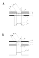
- FIG. 7 is for explaining the spatial filter processing by the spatial processing unit 79, and shows the gradation (luminance) in each of the liquid crystal cells 2, 3 along with the schematic sectional views of the front liquid crystal cell 2 and the rear liquid crystal cell 3. Yes.
- the front liquid crystal cell 2 displays the display element a11
- the rear liquid crystal cell 3 displays the display element a12 at a position corresponding to the display position of the display element a11 in the front liquid crystal cell 2. Since the display element a12 is blurred by the spatial filter process, the width w12 of the display element a12 is larger than the width w11 of the display element a12.
- the gradation of the display element a11 is constant at the original gradation value of the display element a11 within the transmission range.
- the gradation of the display element a11 has a mountainous distribution as indicated by a solid line.
- the rear image signal Sig_RE is processed so that the transmissive pixel range in the rear liquid crystal cell 3 is wider than that of the front liquid crystal cell 2 and the above-described gradual gradation change occurs and the image is blurred. become.
- FIG. 8A and 8B show schematic sectional views of the front liquid crystal cell 2 and the rear liquid crystal cell 3 and the gradation (luminance) in each of the liquid crystal cells 2 and 3 as in FIG.
- FIG. 8A shows the case where the rear image signal Sig_RE is subjected to the spatial filter processing
- FIG. 8B shows the case where the spatial filter processing is not performed.
- the display element a13 displayed on the rear liquid crystal cell 3 has the same width as the display element a11 displayed on the front liquid crystal cell 2, as shown in FIG. Is also steep.
- the display element a11 is observed in the range C11.
- the range C11 there is a portion where the light transmittance in the front liquid crystal cell 2 is high, but the light transmittance in the rear liquid crystal cell 3 is low. For this reason, a part of the display element a11 may be cut off and visually recognized.
- the light transmittance in the front liquid crystal cell 2 is low, but the light transmittance in the rear liquid crystal cell 3 is high. Then, when the transmittance of the front liquid crystal cell 2 in the range C13 is not sufficiently low, a double image may be generated in the display image.
- the display element a12 displayed on the rear liquid crystal cell 3 is blurred by the spatial filter processing, the display element a12 displayed on the front liquid crystal cell 2 becomes wider and wide. The brightness changes gently.
- the light transmittance of the display element a11 is high, and the light transmittance of the display element a12 is gentle. Since it changes, it is difficult for image defects to occur.
- the display device 1 can reduce the possibility that a double image will be generated in the display image. As a result, the display device 90 can improve the image quality.
- the spatial filter processing in the spatial processing unit 79 is controlled by the filter control unit 15.
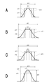
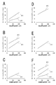
- examples of changing the filter characteristics of the spatial filter processing in the spatial processing unit 79 are shown in FIGS. 9A, 9B, 9C, and 9D.
- the control of the filter characteristics here refers to the filter characteristics for obtaining the gradation distribution shown in FIGS. 7 and 8A. That is, changing the filter characteristics and changing the filter passing waveform shape with respect to the rear image signal Sig_RE causes the rear image signal to be wider in the rear liquid crystal cell 3 than in the front liquid crystal cell 2. This means that the shape of how the gradation value spreads is varied when the spatial filter processing is applied to the.
- the waveform shape of the signal passing through the filter characteristic set by the filter coefficient that is, the shape of the gradation distribution shown in FIGS. 9A, 9B, 9C, and 9D will be referred to as a “filter shape”.
- the filter control unit 15 variably sets a parameter for setting the filter shape with respect to the spatial processing unit 79 by the control signal FC.
- a peak width d11, a filter pass width d12, and a peak value d13 are shown as parameters.
- the filter shape is varied by at least one or a combination of these three parameters.
- the peak width d11 is a width of a range in which the level of the rear image signal Sig_RE that becomes gentle by the spatial filter processing is substantially the original gradation value (peak value) of the pixel.
- the filter pass width d12 is the width of the range of the rear image signal Sig_RE that becomes gentle by the spatial filter processing (the width including the tail portion of the signal by the low pass processing). In other words, this corresponds to the transmission pixel range (blurring range) of the rear liquid crystal cell 3 when the transmission pixel range of the rear liquid crystal cell 3 is wider than the transmission pixel range of the front liquid crystal cell 2.
- the peak value d13 is a gradation value that is the peak of the corresponding pixel of the rear image signal Sig_RE that becomes gentle by the spatial filter processing.
- the filter characteristics of FIGS. 9A, 9B, 9C, and 9D are only examples, and the waveform shapes as the filter characteristics are not uniquely determined by the peak width d11, the filter pass width d12, and the peak value d13, but various. Filter characteristics are assumed. For example, even if the peak width d11, the filter passing width d12, and the peak value d13 are the same as those in FIG. 9A, the filter characteristics are not limited to the solid line filter characteristics, and examples shown by a one-dot chain line or a two-dot chain line are also conceivable.
- the image quality is improved by reducing image loss and flare (black floating) by variably controlling the shape of the filter that blurs the image of the rear liquid crystal cell 3 in accordance with the ambient illuminance.
- FIG. 10 shows the change in light receiving sensitivity depending on the eye's iris (aperture), with the horizontal axis representing the total amount of light entering the human eye (ambient ambient illuminance) and the vertical axis representing luminance.
- the luminance range of the image displayed by the liquid crystal display panel 1 is constant regardless of the ambient environment illuminance, as shown as the monitor display range.
- the dynamic range of the human eye changes depending on the ambient illuminance as shown by the range of the high-luminance line UL (upper limit of visibility) and the low-luminance side line LL (lower limit of visibility). To do. For this reason, when the ambient illuminance increases, it seems that the apparent brightness of the liquid crystal display panel 1 having a constant luminance is relatively dark. Since humans cannot recognize the gradation of the luminance below the line LL on the low luminance side, the luminance of the low gradation portion of the liquid crystal display panel 1, that is, the luminance of the shaded portion in the figure is identified when the ambient environment illuminance is high. Cannot be done (the shaded areas all look the same black).
- FIG. 11 shows how the display image is seen according to ambient illuminance. It is assumed that a white image with a small area is displayed on a black background as shown in FIG. 11A. In this case, the rear liquid crystal cell 3 side is blurred by spatial filter processing. The image on the front liquid crystal cell 2 side and the front image signal Sig_FR (display element a11), and the image on the rear liquid crystal cell 3 side and the rear image signal Sig_RE (display element a12) in this case are shown in FIG. 11B. In this way, the image is blurred and widened by the image processing of the rear liquid crystal cell 3 so that the image is not lost even when viewed obliquely when the front liquid crystal cell 2 and the rear liquid crystal cell 3 are viewed in an overlapping manner.
- Sig_FR display element a11
- Sig_RE display element a12
- FIG. 11D shows the difference in appearance due to the ambient illuminance with respect to the liquid crystal display panel 1 thus driven to display, including visual recognition from the front or oblique direction as shown in FIG. 11C.
- FIG. 11D the way the viewer sees when viewed from the front and obliquely from the left is shown in bold lines when the ambient light is dark and bright.
- the broken lines are the waveforms of the display elements a11 and a12 shown in FIG. 11B.
- the transmitted light of the blurred portion of the rear image is recognized as flare FL (black floating) through the front liquid crystal cell 2 in both the front view and the oblique view.
- the apparent contrast CM is lowered, and it is easy to perceive image quality degradation.
- the visual range of the entire display looks dark due to the shift of the visibility range described with reference to FIG. 10, and it becomes difficult to identify the low gradation side.
- the flare FL becomes difficult to see, but this time, the white image portion looks dark particularly when viewed from an oblique direction.
- the low gradation is raised by the influence of the external light reflection RF.
- FIG. 12 shows how the ambient environment illuminance and the rear image signal Sig_RE are viewed according to the filter shape of the spatial filter processing.
- FIG. 12A shows two types of filter shapes as shape (1) and shape (2).
- FIG. 12B the case where the shape (1) and the shape (2) are used as the filter shape is shown in the same manner as FIG. 11D in each of the front view and the oblique view.
- the shape (1) that is, the blur amount (transmitted light amount) of the rear image
- the flare FL is not noticeable and is good when the surroundings are dark. That is, the transmitted light in the blurred portion of the rear image is reduced.
- the apparent contrast CM may be lowered, particularly when viewed from an oblique direction, or the image may appear to be missing. This is because the effect of blurring the rear image described with reference to FIG.
- the blurring amount (transmitted light amount) of the shape (2) that is, the rear image
- the range of the flare FL becomes large, so that the image quality is easily deteriorated. This is because the transmitted light in the blurred portion of the rear image increases.
- the flare FL does not matter to the viewer due to the visibility described with reference to FIG. 10, and the transmitted light range is widened in oblique viewing, so the contrast CM is improved and the image is not easily lost.
- the amount of blur of the rear image processing appropriate for the ambient environment illuminance is different.
- the shape (1) small amount of blur
- the shape (2) large blur amount
- the filter control unit 15 variably controls the filter shape according to the detection value of the illuminance sensor 40.
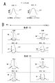
- FIG. 13 shows an example of filter control.
- FIG. 13A shows an input signal as a one-dot image.
- FIG. 13B shows the front image signal Sig_FR (display element a11) in this case.
- FIG. 13C shows the rear image signal Sig_RE (display element a12) in a state of being superimposed on the broken display element a11.
- a peak width d11, a filter pass width d12, and a peak value d13 are used as parameters for the filter processing.
- the spatial processing unit 79 sets a filter coefficient by instructing these three parameters, and performs spatial filtering processing of the instructed filter characteristic.
- the filter control unit 15 includes, for example, table data that stores a peak width d11, a filter passage width d12, and a peak value d13 corresponding to the value of the ambient environment illuminance. Then, the filter control unit 15 sequentially monitors the detection value of the illuminance sensor 40, reads the peak width d11 and the like corresponding to the detection value from the table, and supplies them as a control signal FC to the space processing unit 79.
- the filter control unit 15 may calculate parameters such as the peak width d11 by a predetermined calculation process using the detection value of the illuminance sensor 40 instead of the table.
- FIG. 13D shows an example in which the peak width d11 and the filter passage width d12 are changed in accordance with the ambient environment illuminance.
- the values of the peak width d11 and the filter passage width d12 may be stored according to each value of the ambient environment illuminance.
- the filter is so arranged that the darker the surroundings, the smaller the peak width d11 and the filter passing width d12 (the blurring amount becomes smaller), and the brighter the peak width d11 and the filter passing width d12 become larger (the blurring amount becomes larger).
- the shape is controlled. That is, as described with reference to FIG. 12B, filter control is performed so as to reduce image quality degradation in accordance with the ambient environment illuminance.
- FIG. 14 shows the same format as FIG. 13D.
- FIG. 14A shows an example in which the peak width d11 and the peak value d13 are variably controlled according to the ambient environment illuminance.
- FIG. 14B is an example in which the filter passage width d12 and the peak value d13 are variably controlled according to the ambient environment illuminance.
- FIG. 14C is an example in which only the peak width d11 is variably controlled according to the ambient environment illuminance.
- FIG. 14D is an example in which only the filter passage width d12 is variably controlled according to the ambient environment illuminance.
- FIG. 14E is an example in which only the peak value d13 is variably controlled according to the ambient environment illuminance.
- FIG. 14A shows an example in which the peak width d11 and the peak value d13 are variably controlled according to the ambient environment illuminance.
- FIG. 14B is an example in which the filter passage width d12 and the peak value d13 are variably controlled
- the peak width d11, the filter passage width d12, and the peak value d13 are variably controlled according to the ambient environment illuminance.
- the peak width d11 is variably controlled in each of the above cases, the darker the width, the smaller the brighter, the brighter the width.
- the filter passing width d12 is variably controlled, the width is narrowed as the darkness is increased, and the width is increased as the brightness is increased.
- the peak value d13 is variably controlled, the darker the peak value, the lower the bright value, and the brighter the peak value.
- the filter control unit 15 continuously performs the process of FIG. 15 while the image display is being performed on the liquid crystal display panel 1.
- the filter control unit 15 starts the process of FIG. 15 in response to the start of image display on the liquid crystal display panel 1, and ends the control from step S100 when the image display of the liquid crystal display panel 1 is turned off. It becomes.
- the filter control unit 15 acquires the detection value of the illuminance sensor 40 in step S101, and determines whether or not the illuminance change has occurred in step S102. In this case, a slight change in the detected value is ignored, and it is determined whether or not a significant change in illuminance has occurred so as to change the parameter of the spatial filter processing. Details will be described later. If no significant illuminance change has occurred, the filter control unit 15 returns from step S103 to S100, S101, and continues to monitor the detection value of the illuminance sensor 40.
- the filter control unit 15 proceeds from step S103 to S104, and acquires a filter parameter. That is, the table is referred to by the currently detected illuminance value, and a part or all of the peak width d11, the filter passing width d12, and the peak value d13 corresponding to the current illuminance is acquired.
- the filter control unit 15 supplies the acquired parameters to the spatial processing unit 79 in the rear image generation unit 51.
- the spatial processing unit 79 changes the filter parameter accordingly. That is, the filter shape of the spatial filter process is changed and controlled.
- the spatial filter processing is sequentially controlled based on the current illuminance, so that it is possible to reduce the deterioration in image quality due to the amount of ambient light.
- Steps S100, S101, and S102 are the same as those in FIG. If it is determined that there is a significant change in illuminance, the filter control unit 15 proceeds from step S103 to S104.
- step S102 for detecting a significant change in illuminance will be described with reference to FIG.
- the process of FIG. 17 can also be applied to step S102 of FIG.
- step S201 of FIG. 17 the filter control unit 15 substitutes the current detected illuminance value into the variable SDdet.
- step S202 the filter control unit 15 subtracts the variable SDdet from the variable SDnew to obtain the change amount ⁇ SD.
- the variable SDnew is a detected value of illuminance when the previous filter control was performed (that is, when it was determined that there was a significant change in illuminance last time), and is a value substituted in step S205 at that time. Therefore, the amount of change ⁇ SD indicates the amount of change from the illuminance value when the previous significant illuminance change has occurred with respect to the current illuminance value.
- the flag FSD is a flag indicating the presence or absence of a significant illuminance change.
- the filter control unit 15 assumes that there is a significant change in illuminance compared to the previous control, that is, an illuminance change in which the filter shape should be changed.
- step S205 the filter control unit 15 substitutes the value of the variable SDdet for the variable SDnew. This is a process in which the current illuminance value is the latest illuminance value for which filter shape control is performed, and can be used in the next step S202.
- the filter control unit 15 acquires a filter parameter. That is, the parameter corresponding to the current illuminance is acquired by referring to the table based on the currently detected illuminance value (value of the variable SDnew).
- value of the variable SDnew value of the variable
- step S111 the filter control unit 15 compares the currently controlled filter pass width d12 with the filter pass width d12 acquired according to the new illuminance value, and obtains the change width.
- step S112 the filter control unit 15 compares the change width with a preset maximum step width.
- the maximum step width is the maximum change amount to be changed by one control.
- the maximum step width is set to a change amount that does not cause a rapid parameter fluctuation.
- the filter control unit 15 proceeds to step S113, and supplies the parameter (filter passing width d12) acquired according to the detected value of the current illuminance to the spatial processing unit 79 in the rear image generation unit 51.
- the spatial processing unit 79 changes the filter parameter accordingly. That is, the filter shape of the spatial filter process is changed and controlled.
- the spatial processing unit 79 changes the filter parameter accordingly.
- the filter shape corresponding to the current illuminance has not been reached at one time.
- the process proceeds from step S103 to S110 to S115, and the parameter changed within the maximum step width is transmitted to the spatial processing unit 79 again.
- the filter shape is gradually changed by a plurality of times of control within the maximum step width until the target parameter is reached.
- step S104 the processing from step S104 is performed according to the new illuminance.
- the change width in step S111 is a difference from the parameter value during the stepwise control.
- variable control may be performed stepwise for each parameter that exceeds the maximum step width.
- the image processing apparatus 10 uses a rear image signal Sig_RE and a front image signal Sig_FR as image signals for the liquid crystal display panel 1 in which a display image is generated by light passing through the rear liquid crystal cell 3 and the front liquid crystal cell 2. Based on the detection values of the image processing unit (dual cell image processing unit 12) to be generated and the illuminance sensor 40 for detecting the illuminance in the vicinity of the display panel, the dual cell image processing unit 12 performs spatial filter processing applied to the rear image signal Sig_RE.
- the filter control part 15 to control is provided.
- the appearance of the user changes depending on the illuminance around the display device 90, so that the lack of image is easily visible or the influence of flare increases due to the illuminance (brightness or darkness).
- spatial filter control of the rear image signal Sig_RE According to, spatial filter processing corresponding to illuminance can be performed. Specifically, it becomes possible to make the flare in the dark state inconspicuous, to improve the image missing at the time of viewing from the oblique direction in the bright state, and to improve the contrast deterioration of the appearance.
- the dual cell image processing unit 12 uses the spatial processing unit 79 to expand the transmission pixel range of the image in the rear liquid crystal cell 3 relative to the image of the front liquid crystal cell 2 with respect to the rear image signal Sig_RE. Processing is performed. That is, spatial filter processing is performed so as to blur the rear image. Specifically, the low-pass filter for the rear image signal Sig_RE is set so that the transmission pixel range of the rear liquid crystal cell 3 by the rear image signal Sig_RE is wider than the transmission pixel range of the front liquid crystal cell by the front image signal Sig_FR. Apply the following process. By doing so, for example, it becomes difficult to generate a double image in the display image or the viewing angle can be improved. However, the spatial filter is controlled according to the illuminance. This makes it possible to deal with flare in a dark state, image loss in a bright state, and contrast deterioration when performing double image prevention and viewing angle improvement.
- the filter control unit 15 variably controls a parameter for changing the filter characteristics in the spatial filter processing based on the detection value of the illuminance sensor 40. That is, when performing spatial filter processing on the rear image signal so that the range of the transmissive pixel of the rear liquid crystal cell is wider than the range of the transmissive pixel of the front liquid crystal cell, the filter characteristics are changed, and the rear image signal is changed.
- the shape of the passage waveform (the shape of how the gradation value spreads) is varied.
- the filter passage width d12 is given as a parameter for changing the filter characteristics.
- the filter passing width is the width of the range of the rear image signal that becomes gentle by the spatial filter processing (the width including the bottom portion of the signal by the low-pass processing), and corresponds to the range of transmission pixels (blurring range).
- the filter passing width is varied according to the illuminance.
- the peak width d11 is given as a parameter for changing the filter characteristics.
- the peak width is the width of a range that is the original gradation value (peak value) of the pixel of the rear image signal that becomes gentle by the spatial filter processing. This peak width is varied according to the illuminance.
- the variable control of the peak width d11 (FIG. 14C)
- both the peak width d11 and the filter passage width d12 may be variably controlled (FIG. 13D). This can also cope with image degradation corresponding to light and dark.
- the peak value d13 is given as a parameter for changing the filter characteristics.
- the peak value is the gradation value of the peak of the rear image signal that becomes gentle by the spatial filter processing, and this peak value is made variable according to the illuminance.
- the variable control of the peak value d13 (FIG. 14E) it is possible to adjust the amount of transmitted light according to light and dark, and cope with image degradation according to light and dark.
- both the peak value d13 and the filter passage width d12 may be variably controlled (FIG. 14B).
- both the peak value d13 and the peak width d11 may be variably controlled (FIG. 14A).
- all of the peak value d13, the filter passing width d12, and the peak width d11 may be variably controlled (FIG. 14F). These can also cope with the deterioration of the image according to the brightness.
- the filter control unit 15 decreases the image blur range of the rear liquid crystal cell 3 as the illuminance decreases, and increases the image blur range of the rear liquid crystal cell 3 as the illuminance increases.
- the spatial filter process is controlled so as to be (see FIGS. 13 and 14).
- flare in a dark state can be made inconspicuous by narrowing the image blur range of the rear liquid crystal cell.
- the ambient illuminance is high, widening the image blur range of the rear liquid crystal cell can improve image loss and visual contrast degradation when viewed from an oblique direction in a bright state.
- the filter control unit 15 decreases the light transmission amount of the rear liquid crystal cell as the illuminance is lower, and the light transmission amount of the rear liquid crystal cell is higher as the illuminance is higher.
- the spatial filter processing is controlled so as to increase (see FIG. 14).
- the peak value d13 When the ambient illuminance is low, the flare in the dark state can be made inconspicuous by controlling the peak value d13 so as to reduce the transmission amount of the rear liquid crystal cell.
- the peak value d13 is controlled so as to increase the amount of transmission through the rear liquid crystal cell, thereby improving image loss and visual contrast degradation when viewed from an oblique direction in a bright state. it can.
- the filter control unit 15 changes the filter characteristics in a stepwise manner when a change in illuminance is detected based on the detection value of the illuminance sensor 40 (see FIG. 16). That is, when a change in illuminance is detected, the filter shape corresponding to the new illuminance is not changed at once, but gradually changed. If the filter shape is rapidly changed, screen flicker may occur due to a difference in response characteristics between the front liquid crystal cell 2 and the rear liquid crystal cell 3. Therefore, an event that the screen flickers can be prevented by not following the large illuminance change in a short time.
- variable control of the spatial filter process according to the illuminance change is performed. (See FIG. 17). That is, the variable control of the spatial filter processing is not performed unnecessarily due to a slight change in illuminance. As a result, control that does not excessively respond to a slight change in illuminance is realized, and flickering of the screen due to excessive spatial filter control can be prevented.
- the front image generation unit 52 generates the front image signal by dividing the rear image signal Sig_RE from the image signal Sig_in. That is, for example, R, G, B gradation values as the image signal Sig_in which is a color image signal, the gradation values of the rear image signal Sig_RE are respectively divided to obtain R, G, B gradations as the front image signal. Get the value.
- R, G, B gradation values as the image signal Sig_in which is a color image signal
- the gradation values of the rear image signal Sig_RE are respectively divided to obtain R, G, B gradations as the front image signal. Get the value.
- the dual cell image processing unit 12 includes a light amount correction unit 53 that multiplies the rear image signal Sig_RE by a correction coefficient kLC corresponding to a light amount component incident on the front liquid crystal cell 2, and the front image generation unit 52
- the front image signal Sig_FR is generated by dividing the rear image signal Sig_RE multiplied by the correction coefficient kLC from the signal Sig_in. It is possible to obtain a front image signal Sig_FR in consideration of a light amount component incident on the front liquid crystal cell 2 from the rear liquid crystal cell 3, and to obtain an appropriate gradation as an image obtained by overlapping the rear liquid crystal cell 3 and the front liquid crystal cell 2. can do.
- the display device 90 includes the dual cell type liquid crystal display panel 1 in which a display image is generated by light passing through the rear liquid crystal cell and the front liquid crystal cell, and the dual cell image processing unit 12 described above.
- the liquid crystal display panel 1 a backlight 5, a rear liquid crystal cell 3, a diffusion layer 4, and a front liquid crystal cell 2 are arranged in this order.
- a liquid crystal display panel 1 of the dual liquid crystal cell type it is possible to reduce image quality degradation caused by ambient environment illuminance.
- An image processing unit that generates a rear image signal for the rear liquid crystal cell and a front image signal for the front liquid crystal cell as an image signal for a display panel in which a display image is generated by light passing through the rear liquid crystal cell and the front liquid crystal cell.
- An image processing apparatus comprising: a filter control unit that controls a spatial filter process applied to a rear image signal in the image processing unit based on a detection value of an illuminance sensor that detects an illuminance near the display panel.
- the image processing apparatus performs the spatial filter processing for expanding a transmission pixel range of an image in a rear liquid crystal cell as compared with an image of a front liquid crystal cell with respect to a rear image signal.
- the filter control unit variably controls a parameter that changes a filter characteristic in the spatial filter processing based on a detection value of the illuminance sensor.
- the parameter is a filter passage width of a rear image signal.
- the parameter is a peak width of a rear image signal.
- the image processing apparatus according to any one of (3) to (5), wherein the parameter is a peak value of a rear image signal.
- the filter control unit is configured such that, as the detection value of the illuminance sensor, the lower the illuminance, the narrower the image blur range of the rear liquid crystal cell, and the higher the illuminance, the wider the image blur range of the rear liquid crystal cell.
- the image processing apparatus according to any one of (1) to (6), wherein the image processing apparatus controls filter processing.
- the filter control unit decreases the light transmission amount of the rear liquid crystal cell as the illuminance is lower, and increases the light transmission amount of the rear liquid crystal cell as the illuminance is higher.
- the image processing device according to any one of (1) to (7), wherein the spatial filter processing is controlled.
- the said filter control part controls the said spatial filter process so that a filter characteristic may be changed in steps, when an illuminance change is detected by the detection value of the said illuminance sensor. Any one of said (1) thru
- the filter control unit performs variable control of the spatial filter processing according to the illuminance change when the detection value of the illuminance sensor becomes a value exceeding a predetermined change width from the value when the previous filter control is performed.
- the image processing apparatus according to any one of (1) to (9).
- a display panel in which a display image is generated by light passing through the rear liquid crystal cell and the front liquid crystal cell;
- An image processing unit for generating a rear image signal for the rear liquid crystal cell and a front image signal for the front liquid crystal cell;
- An illuminance sensor for detecting illuminance in the vicinity of the display panel;
- a filter control unit that controls a spatial filter process applied to a rear image signal in the image processing unit based on a detection value of the illuminance sensor.
- Image processing procedure for generating a rear image signal for the rear liquid crystal cell and a front image signal for the front liquid crystal cell as an image signal for a display panel in which a display image is generated by light passing through the rear liquid crystal cell and the front liquid crystal cell
- a filter control procedure for controlling a spatial filter process applied to a rear image signal in the image processing procedure based on a detection value of an illuminance sensor that detects an illuminance near the display panel.
- SYMBOLS 1 Liquid crystal display panel, 2 ... Front liquid crystal cell, 3 ... Rear liquid crystal cell, 4 ... Diffusion layer, 5 ... Back light, 10 ... Image processing apparatus, 11 ... Display image processing part, 12 ... Dual cell image processing part, 15 DESCRIPTION OF SYMBOLS ... Filter control part, 20 ... Front liquid crystal cell drive part, 30 ... Rear liquid crystal cell drive part, 40 ... Illuminance sensor, 51 ... Rear image generation part, 52 ... Front image generation part, 53 ... Light quantity correction part, 54, 57 ... Panel gamma processing unit, 55, 58 ... adjustment unit, 56 ... rear output unit, 57 ... front output unit, 70 ... gray scale conversion unit, 72 ... gradation value conversion unit, 73 ... LUT, 74 ... gamma conversion unit, 75 ... Gradation holding section, 78 ... Composition section, 79 ... Spatial processing section, 90 ... Display device
Landscapes
- Physics & Mathematics (AREA)
- Engineering & Computer Science (AREA)
- Chemical & Material Sciences (AREA)
- Crystallography & Structural Chemistry (AREA)
- General Physics & Mathematics (AREA)
- Nonlinear Science (AREA)
- Theoretical Computer Science (AREA)
- Computer Hardware Design (AREA)
- Mathematical Physics (AREA)
- Optics & Photonics (AREA)
- Control Of Indicators Other Than Cathode Ray Tubes (AREA)
- Liquid Crystal Display Device Control (AREA)
- Liquid Crystal (AREA)
- Controls And Circuits For Display Device (AREA)
- Ultra Sonic Daignosis Equipment (AREA)
Abstract
Description
ところが、空間フィルタを用いてリア液晶セルの画像をぼかす場合、一定の表示(輝度)であっても表示装置の周囲環境照度によって人の目の視感度(明るさの感じ方)が変わり、周囲環境照度が明るい場合は、相対的に表示装置が暗く見えるため視野角がより狭く感じ、周囲環境照度が暗い場合は、輝度視野角はより広く感じるが、フレア(黒浮き)と呼ばれるコントラスト低下による画質劣化が強調するように見える場合がある。
本技術はこのデュアル液晶セル型の表示装置を用いる場合に、このような周囲環境照度による画質劣化を軽減できるようにすることを目的とする。
この画像処理装置が処理対象とする画像信号は、デュアル液晶セル型の液晶表示パネルで用いる画像信号である。画像処理装置は、デュアル液晶セル型の液晶表示パネルのフロント液晶セルとリア液晶セルのそれぞれに対する画像信号の処理を行う。この場合にリア画像信号に対する空間フィルタ処理を行うことがあるが、その空間フィルタ処理を、照度に応じて制御する。
即ちリア画像をぼかすように空間フィルタ処理を行う。具体的には、フロント画像信号によるフロント液晶セルの画像に対して、リア液晶セル側の透過する画素の範囲が広くされて画像がぼかされるように、リア画像信号に対する低域通過フィルタのような処理を施す。
即ちフロント液晶セルの透過画素の範囲よりもリア液晶セルの透過画素範囲が広くなるようにリア画像信号に対する空間フィルタ処理を施す場合に、その通過波形の形状(階調値の広がり方の形状)を可変する。
フィルタ通過幅は、空間フィルタ処理でなだらかになるリア画像信号の範囲の幅(低域通過処理による信号の裾野の部分を含めた幅)である。即ちフロント液晶セルの透過画素の範囲よりもリア画像信号によるリア液晶セルの透過画素の範囲が広くなるようにする場合の、透過画素の範囲(ぼかし範囲)に相当する。このフィルタ通過幅を照度に応じて可変する。
ピーク幅は空間フィルタ処理でなだらかになるリア画像信号の当該画素の本来の階調値(ピーク値)となる範囲の幅である。ピーク幅を照度に応じて可変する。
ピーク値は空間フィルタ処理でなだらかになるリア画像信号のピークの階調値である。通常は該当画素の本来の階調値であるが、このピーク値を照度に応じて可変するようにする。
画像ぼけ範囲の制御は、例えばリア画像信号のフィルタ形状の制御で行う。
光の透過量の制御は、例えばリア画像信号の階調のピーク値の制御で行う。
即ち、照度変化を検知したときに、一気に新たな照度に応じたフィルタ形状まで変化させるようにはせず、徐々に変化させるようにする。
即ち、微少な照度変化によりむやみに空間フィルタ処理の可変制御が行われないようにする。
この表示装置においては、表示パネルは、例えば光源部と、リア液晶セルと、拡散層と、フロント液晶セルが、この順番で配置され、いわゆるデュアル液晶セル型の液晶表示パネルを構成する。このようなデュアル液晶セル型の液晶表示パネルに対するリア画像信号について、照度に応じた空間フィルタ制御が行われるようにする。
本技術に係る画像処理方法は、上記の画像処理装置における画像処理部とフィルタ制御部で行われる処理として、画像処理手順と、フィルタ制御手順とが行われるものである。
なお、ここに記載された効果は必ずしも限定されるものではなく、本開示中に記載されたいずれかの効果であってもよい。
<1.表示装置の構成>
<2.デュアルセル画像処理部の構成>
<3.実施の形態における空間フィルタ制御>
<4.第1の実施の形態の処理>
<5.第2の実施の形態の処理>
<6.まとめ及び変形例>
なお説明上、3原色である赤色(red)、緑色(green)、青色(blue)は、それぞれアルファベットでR,G,Bと表記する。
図1は実施の形態の表示装置90の構成を示している。表示装置90は、液晶表示パネル1、画像処理装置10、フロント液晶セル駆動部20、リア液晶セル駆動部30を有する。
バックライト5の前面側に、リア液晶セル3、拡散層4、フロント液晶セル2がこの順番で重なるように配置されており、視認者はフロント液晶セル2の前面側から表示された画像を見ることになる。
フロント液晶セル2、リア液晶セル3はそれぞれ1つの液晶表示パネルを形成するが、本実施の形態では、デュアル液晶セル型の表示パネル全体を液晶表示パネル1と呼ぶこととする。
画像処理装置10は表示画像処理部11、デュアルセル画像処理部12、フィルタ制御部15を有する。
表示画像処理部11は、入力された画像信号S1に対して、必要なデコード処理、輝度処理、色処理、解像度変換等を行い、処理後の画像信号Sig_inをデュアルセル画像処理部12に供給する。少なくとも画像信号Sig_inの段階では、R、G、Bの各色の階調値を示すカラー画像信号とされている。
即ちデュアルセル画像処理部12は入力された画像信号Sig_inに対する信号処理を行い、フロント液晶セル2に対する画像信号(フロント画像信号Sig_FR)、及びリア液晶セル3に対する画像信号(リア画像信号Sig_RE)を生成して出力する。
フロント画像信号Sig_FRはR、G、Bの階調値を含むカラー画像信号である。一方、リア画像信号Sig_REはグレースケールとしての階調値を含む白黒(グレースケール)画像信号である。
このフィルタ制御部15は、デュアルセル画像処理部12における空間フィルタ処理についての制御を行う。これについても詳細は後述するが、デュアルセル画像処理部12では、リア画像信号Sig_REについては、画像をぼかすようにする空間フィルタ処理を施している。フィルタ制御部15は、この空間フィルタ処理のフィルタ特性を制御する。具体的にはフィルタ制御部15は、制御信号FCにより、例えばフィルタ特性を規定するパラメータを指定する処理を行う。
特にフィルタ制御部15は、このようなフィルタ制御を照度センサ40の検出値に基づいて行う。
例えば照度センサ40は表示装置90としての筐体の表面等に検出窓が設けられて照度を検出する。特には液晶表示パネル1の前面側の照度を検出するように配置されている。
なお、照度センサ40は表示装置90とは別体のものでもよい。
画像処理装置10から出力されるリア画像信号Sig_REはリア液晶セル駆動部30に供給される。リア液晶セル駆動部30はリア画像信号Sig_REに基づいてリア液晶セル3を駆動し、白黒画像表示を実行させる。
フロント液晶セル駆動部20は、表示制御部21と、垂直駆動部22と、水平駆動部23を有し、これらの構成でフロント液晶セル2を駆動する。
垂直駆動部22は、表示制御部21から供給される制御信号に基づいて、フロント液晶セル2における表示駆動の対象となる1水平ラインを順次選択する。
水平駆動部23は、表示制御部21から供給される画像信号および制御信号に基づいて、1水平ライン分の画素電圧を生成し、垂直駆動部22が選択した1水平ライン分のサブ画素26(26R,26G,26B)に供給する。
各画素25は、3つのサブ画素26R,26G,26Bを有している。
サブ画素26Rは、赤色のカラーフィルタを有するものであり、サブ画素26Gは、緑色のカラーフィルタを有するものであり、サブ画素26Bは青色のカラーフィルタを有するものである。
これらのサブ画素26R,26G,26Bには、水平駆動部23から画素電圧がそれぞれ供給される。そして、サブ画素26R,26G,26Bは、画素電圧に応じて、光の透過率をそれぞれ変化させるようになっている。
リア液晶セル駆動部30は、表示制御部31と、垂直駆動部32と、水平駆動部33を有し、これらの構成でリア液晶セル3を駆動する。
垂直駆動部32は、表示制御部31から供給される制御信号に基づいて、フロント液晶セル2における表示駆動の対象となる1水平ラインを順次選択する。
水平駆動部33は、表示制御部31から供給される画像信号および制御信号に基づいて、1水平ライン分の画素電圧を生成し、垂直駆動部32が選択した1水平ライン分のサブ画素36に供給するものである。
各画素35は、3つのサブ画素36を有している。各サブ画素36は、カラーフィルタを有しないものである。すなわち、フロント液晶セル2における各サブ画素26R,26G,26Bは、対応する色のカラーフィルタを有するようにしたが、リア液晶セル3における各サブ画素36は、カラーフィルタを有しない。
1つの画素35に属する3つのサブ画素36には、水平駆動部33から同じ画素電圧が供給される。そして、サブ画素36は、画素電圧に応じて、光の透過率を変化させるようになっている。
なお、リア液晶セル3の画素35は、上記の3つのサブ画素分を1つの電極、及びブラックマトリックスの1画素として構成してもよい。即ち、カラーフィルタレスだけでなく、TFT、透明電極、配線、ブラックマトリックスという各液晶構造要素についてもサブ画素を持たない構造とされることもある。その場合、1つの画素35は、フロント液晶セル2における3つのサブ画素26R,26G,26Bに対応することになる。
バックライト5は、例えばLED(Light Emitting Diode)による発光部を備えて発光を行う。
図示するように液晶表示パネル1では、バックライト5、リア液晶セル3、拡散層4、フロント液晶セル2が、この順に配置されており、図3におけるフロント液晶セル2の上面が、表示面DPになっている。
つまり、バックライト5から射出した光が、バックライト5、リア液晶セル3、拡散層4、フロント液晶セル2を順に通過し、視認者に届くようになっている。
フロント液晶セル2およびリア液晶セル3は、互いに離間して配置されている。そして、このフロント液晶セル2とリア液晶セル3の間の空隙8には、拡散層4が配置されている。
なお構成例としては、フロント液晶セル2とリア液晶セル3のセル間を隙間なく接着層で密着させる場合もある。
基板122,124は、例えばガラス基板により構成されるものであり、互いに対向するように配置されている。
基板122の基板124側の面には、サブ画素26ごとに画素電極が形成され、上述の水平駆動部23により画素電圧が印加されるようになっている。
基板124の基板122側の面には、各サブ画素26に共通の電極が形成されている。また、基板124には、カラーフィルタや、ブラックマトリクスが形成されている。
液晶層123は、基板122と基板124との間に封止されたものであり、基板122の画素電極に印加された画素電圧に応じて、光の透過率が変化するものである。
偏光板121は、基板122の光入射側に貼り付けられており、偏光板125は、基板124の光出射側に貼り付けられている。偏光板121の透過軸と偏光板125の透過軸とは、互いに交差するようになっている。
基板132,134は、例えばガラス基板により構成されるものであり、互いに対向するように配置されている。
基板132の基板134側の面には、サブ画素26ごとに画素電極が形成され、上述の水平駆動部33により画素電圧が印加されるようになっている。
なお上述のようにサブ画素を持たない構造も考えられ、その場合、画素35ごとに画素電極が形成される。
基板134の基板132側の面には、各サブ画素36に共通の電極が形成されている。また、基板134には、ブラックマトリクスが形成されている。そして基板134には、フロント液晶セル2の基板124とは異なり、カラーフィルタは形成されていない。
液晶層133は、基板132と基板134との間に封止されたものであり、基板132の画素電極に印加された画素電圧に応じて、光の透過率が変化するものである。
偏光板131は、基板132の光入射側に貼り付けられており、偏光板135は、基板134の光出射側に貼り付けられている。偏光板131の透過軸と偏光板135の透過軸とは、互いに交差するようになっている。
この拡散層4は、表示画像におけるモアレを低減するためのものである。すなわち、液晶表示パネル1は、2枚の液晶表示パネルであるフロント液晶セル2とリア液晶セル3を重ねて配置しているため、表示画像にモアレが生じてしまうおそれがある。そこで液晶表示パネル1では、拡散層4をフロント液晶セル2とリア液晶セル3の間に配置することにより、モアレを低減し、画質の低下を抑えるようにしている。
この場合、拡散層4とフロント液晶セル2との間、および拡散層4とリア液晶セル3との間のうちの一方または双方に透明材料層を形成してもよい。
また、拡散層4をフロント液晶セル2に隣接するように(dFR1=0)配置するのがより望ましい。拡散層4をフロント液晶セル2に近づけるほど、モアレをより効果的に抑制することができ、また鮮鋭度を高めることができるためである。
また、拡散層4のヘイズ値が低い場合でも、例えば、拡散層4をフロント液晶セル2に近付けて配置することにより所望の画質を得ることができる。
発光アレイ42は例えばLEDが配列されて構成されている。
デュアルセル画像処理部12の構成を図4,図5で説明する。
図4はデュアルセル画像処理部12のブロック図であり、図5は図4におけるリア画像生成部51内を詳細に示したブロック図である。
画像信号Sig_inは例えばR、G、Bについてそれぞれ10ビットによる1024階調の信号である。もちろん1024階調(10ビット)とするのは説明上の一例に過ぎず、より少ない又はより多い階調(ビット数)の信号としてもよい。
リア画像信号Sig_REはパネルガンマ処理部54でリア液晶セル3に応じたガンマ処理が施された後、調整部55で必要な調整処理が施される。そしてリア出力部56で遅延調整処理や3つのサブ画素36に対応する並列化等が行われ、リア液晶セル駆動部30に供給される。
なお、上述のようにリア液晶セル3にサブ画素が構成されない場合、リア画像信号Sig_REは、フロント液晶セル2における3つのサブ画素26R,26G,26Bに対応する3つのタイミングのフロント画像信号Sig_FRに対応して出力される。
光量補正係数kLCは例えば固定値である。但し光量補正係数kLCは可変値とすることも考えられる。例えば画像に応じて適応的に光量補正係数kLCが算出されるものとしてもよい。
但し、実際にはリア液晶セル3からの出射からフロント液晶セル2に入射されるまでには光量差が生ずるため、正確には単純な除算ではなく補正が必要である。そこで光量補正部53でリア画像信号Sig_REを補正している(Sig_RE・kLC)。
このため、フロント画像生成部52(除算部52a)では、フロント画像信号Sig_FRを、
Sig_FR=Sig_in/(Sig_RE・kLC)
として算出することとしている。
Sig_FR(R)=Sig_in(R)/(Sig_RE・kLC)
Sig_FR(G)=Sig_in(G)/(Sig_RE・kLC)
Sig_FR(B)=Sig_in(B)/(Sig_RE・kLC)
としてフロント画像信号Sig_FRを生成することになる。
R、G、Bの階調値Sig_FR(R)、Sig_FR(G)、Sig_FR(B)は、それぞれ例えば10ビットで1024階調(0~1023)の信号である。
リア画像生成部51では、入力されたカラー画像信号である画像信号Sig_inを、グレースケール変換部70でグレースケール信号(白黒画像信号)Grに変換する。
グレースケール変換は、係数kR,kG,kBを用いて、
Gr=kR・Sig_in(R)+kG・Sig_in(G)+kB・Sig_in(B)
として行う。
即ち、画像信号Sig_inに含まれるR、G、Bのそれぞれの階調値Sig_in(R)、Sig_in(G)、Sig_in(B)に対応してR用の係数kR、G用の係数kG、B用の係数kBを乗算し、それらを加算することでグレースケール信号Grとする。このグレースケール信号Grは、W(白色)としての階調値(0~1023)となる。
階調変換部72は、LUT(Look Up Table)73とガンマ変換部74で構成される。ガンマ変換部74は、入力されたグレースケール信号Grの階調値をLUT入力信号LUT inとしてLUT73を参照し、対応する出力階調値(LUT出力信号LUTout)を得る。そしてその出力階調値LUToutを合成部78に供給する。
また図6Bは、フロント液晶セル2,リア液晶セル3における光の透過率を表すものである。この図6Bにおいて、横軸は、フロント液晶セル2,リア液晶セル3へ供給される信号の階調レベルを示し、縦軸は、透過率L2,L3を示す。ここで、透過率L2は、フロント液晶セル2における透過率を示し、透過率L3は、リア液晶セル3における透過率を示す。
そこで、液晶表示パネル1では、階調レベルが高い範囲において、リア液晶セル3における透過率L3を一定(100%)にし、階調レベルが上記の例えば約40[%]より低い範囲において、リア液晶セル3における透過率L3を階調レベルに応じて変化させていくようにする。
これにより、液晶表示パネル1では、フロント液晶セル2における透過率L2とリア液晶セル3における透過率L3との積Ltotalが、階調レベルが低い範囲においても、階調レベルが高い範囲と同様に、階調レベルに応じて変化するようにすることができる。従って液晶表示パネル1では、例えば、1枚の液晶セルを用いて構成した場合に比べ、低階調範囲において透過率Ltotalを低くすることができるため、コントラストを高めることができる。
階調変換部72は、この図6Bに示した透過率L3を実現できるように、ガンマ変換を行う。この場合の変換特性が例えば図6Aのようになる。即ち入力階調値が或る階調値より高い範囲において、出力階調値が最高階調値となるようにしている。即ち入力階調値が或る階調値より高い範囲において、出力階調値が最高階調値となるようにしている。
階調保持部75は画像信号Sig_inにおけるR、G、Bのそれぞれの階調値Sig_in(R)、Sig_in(G)、Sig_in(B)のうちで最大値を検出し、検出した最大値に所定の処理を行って信号Mを生成する。この信号Mは合成部78に供給される。
この合成部78の出力(リア画像信号Sig_RE)は、空間処理部79で処理されたうえでリア画像生成部51から出力される。
このことから、大まかに言えば、高階調域の画素についての画像信号Sig_inが入力された場合は、信号Mによる階調値がリア画像信号Sig_REに反映されやすく、低階調域の画素についての画像信号Sig_inが入力された場合は、LUT出力信号LUToutによる階調値がリア画像信号Sig_REに反映されやすいことになる。但し、LUT73の出力階調値は、単純に画像信号Sig_inの階調に応じたものとはならないため一概には言えない。
このような場合を想定して、階調性を保持するために、最大値に基づく信号Mを用いる場合があるようにしている。
例えば空間処理部79はFIR(Finite Impulse Response)フィルタによりフィルタ処理を行うものである。このFIRフィルタは、低域通過フィルタとして機能するものであり、リア液晶セル3に表示する画像をぼかすものである。これにより、表示装置90では、観察者が表示画像を観察したときに、その表示画像に画欠けや2重画が生じるおそれを低減することができるようになっている。FIRフィルタのタップ数は、表示画像に画欠けや2重画が生じないような視野角の目標値θに応じて設定されるものである。
この例では、フロント液晶セル2は表示要素a11を表示し、リア液晶セル3はフロント液晶セル2における表示要素a11の表示位置に対応する位置に、表示要素a12を表示する。表示要素a12は、空間フィルタ処理によりぼかされているため、表示要素a12の幅w12は、表示要素a12の幅w11よりも大きい。
表示要素a11の階調は破線で示すように、透過範囲内で当該表示要素a11の本来の階調値で一定となる。一方、表示要素a11の階調は実線で示すように山なりな分布となる。空間フィルタ処理では、リア液晶セル3における透過画素範囲をフロント液晶セル2よりも広げ、しかも上記のような山なりな階調変化が生じて画像がぼけるような処理をリア画像信号Sig_REに施すことになる。
図8A、図8Bは、図7と同様にフロント液晶セル2,リア液晶セル3の断面模式図と、各液晶セル2,3における階調(輝度)を示している。図8Aはリア画像信号Sig_REに空間フィルタ処理を施した場合、図8Bは空間フィルタ処理を施していない場合である。
表示面の法線方向から角度φの方向にいるユーザが、このような表示画像を観察した場合、範囲C11において、表示要素a11を観察する。
このとき範囲C11において、フロント液晶セル2における光の透過率は高いが、リア液晶セル3における光の透過率は低い部分が生ずる。このため表示要素a11の一部が欠けて視認されしまうことが生じる場合がある。
また範囲C13においては、フロント液晶セル2における光の透過率は低いが、リア液晶セル3における光の透過率は高い。すると、この範囲C13におけるフロント液晶セル2の透過率が十分に低くない場合に、表示画像に2重画が生じてしまうおそれがある。
表示面の法線方向から角度φの方向にいるユーザが、範囲C11において、表示要素a11を観察すると、表示要素a11における光の透過率は高く、また表示要素a12における光の透過率はなだらかに変化するため、画欠けが生じにくいこととなる。
また範囲C12では、フロント液晶セル2における光の透過率は低く、かつリア液晶セル3における光の透過率はなだらかに変化する。よって、表示装置1では、表示画像に2重画が生じるおそれを低減することができる。これらの結果、表示装置90では画質を高めることができる。
本実施の形態では、空間処理部79における空間フィルタ処理がフィルタ制御部15によって制御されることになる。
例えば空間処理部79における空間フィルタ処理のフィルタ特性を変化させる例を図9A、図9B、図9C、図9Dに示している。
ここでいうフィルタ特性の制御は、特に先に図7や図8Aに示した階調分布を得るためのフィルタ特性のことである。即ちフィルタ特性を変化させ、リア画像信号Sig_REに対するフィルタ通過波形形状を変化させることは、フロント液晶セル2の透過画素の範囲よりもリア液晶セル3の透過画素の範囲が広くなるようにリア画像信号に対する空間フィルタ処理を施す場合に、その階調値の広がり方の形状を可変することを意味する。
フィルタ制御部15は、空間処理部79に対して制御信号FCによりフィルタ形状を設定するパラメータを可変設定することになる。
ここではパラメータとしてピーク幅d11、フィルタ通過幅d12、ピーク値d13を示している。この3つのパラメータの少なくとも1つもしくは複数の組み合わせでフィルタ形状を可変する。
フィルタ通過幅d12は、空間フィルタ処理でなだらかになるリア画像信号Sig_REの範囲の幅(低域通過処理による信号の裾野の部分を含めた幅)である。即ちフロント液晶セル2の透過画素の範囲よりもリア液晶セル3の透過画素の範囲が広くなるようにする場合の、リア液晶セル3の透過画素の範囲(ぼかし範囲)に相当する。
ピーク値d13は、空間フィルタ処理でなだらかになるリア画像信号Sig_REの該当画素のピークとなる階調値である。
なお図9A、図9B、図9C、図9Dのフィルタ特性は一例であるとともに、フィルタ特性としての波形形状は、ピーク幅d11、フィルタ通過幅d12、ピーク値d13によって一意に決まるわけではなく、多様なフィルタ特性が想定される。例えば図9Aと同じピーク幅d11、フィルタ通過幅d12、ピーク値d13であっても、フィルタ特性としての実線のフィルタ特性に限らず、一点鎖線や二点鎖線で示すような例も考えられる。
実施の形態では、周囲環境照度に応じてリア液晶セル3の画像をぼかすフィルタ形状を可変制御することにより、画欠けやフレア(黒浮き)を軽減した画質向上を実現するものである。
図10は横軸を人の目に入る総光量(周囲環境照度)、縦軸を輝度として、目の光彩(絞り)による受光感度の変化を示している。
まず、液晶表示パネル1により表示される画像の輝度範囲は、モニタ表示レンジとして示すように、周囲環境照度にかかわらず一定である。
一方で、人の目のダイナミックレンジは、高輝度側のラインUL(視感度の上限値)と低輝度側のラインLL(視感度の下限値)の範囲として示すように、周囲環境照度によって変化する。
このため、周囲環境照度が上がると、一定輝度である液晶表示パネル1の見た目の明るさが相対的に暗くなったように感じてしまう。そして人は低輝度側のラインLLより下の輝度は階調性を認識できないため、周囲環境照度が高いと、液晶表示パネル1の低階調部の輝度、即ち図の斜線部の輝度が識別できなくなる(斜線部の階調は全て同じ黒に見える)。
図11により周囲環境照度による表示画像の見え方について示す。
図11Aのような黒背景に小面積の白画像を表示するとする。この場合に空間フィルタ処理でリア液晶セル3側をぼかす。
この場合のフロント液晶セル2側の画像とフロント画像信号Sig_FR(表示要素a11)、及びリア液晶セル3側の画像とリア画像信号Sig_RE(表示要素a12)を図11Bに示す。このようにリア液晶セル3の画像処理で画像をぼかし広げることでフロント液晶セル2とリア液晶セル3を重ねて見た時に斜め視でも画欠けしないようにしている。
このため見た目のコントラストCMが低下し、画質劣化として知覚しやすくなる。
周囲が明るい場合は、図10で説明した視感度範囲のシフトにより表示全体の見た目が暗く見え、低階調側の識別がしにくくなる。このためフレアFLは見えにくくなるが、今度は白画像の部分が特に斜めから見た時に暗く見える。また外光反射RFの影響で低階調が持ち上げられる。これらにより視認者は、画欠けや見た目のコントラストCMの劣化を知覚しやすくなる。
図12Aに、形状(1)、形状(2)として2種類のフィルタ形状を示している。図12Bではフィルタ形状として形状(1)、形状(2)を用いた場合を、正面視と斜め視の各場合について先の図11Dと同様に示している。
ところが周囲が明るい時は、特に斜めから見た場合に見た目のコントラストCMが低下したり、画欠けしたように見える場合がある。これは図8Aで説明した、リア画像のぼかしによる効果が薄れるためである。
一方、周囲が明るい時は図10で説明した視感度の関係で、視認者にとってはフレアFLが気にならなくなり、また斜め視では透過光範囲が広くなるためコントラストCMが改善され画欠けしにくくなる。
即ちリア画像信号Sig_REについての空間フィルタ処理におけるフィルタ形状を制御することで、周囲環境照度に応じた画質劣化を軽減し、視認者にとって画質向上を知覚させることが可能となる。
そこで本実施の形態では、フィルタ制御部15が照度センサ40の検出値に応じて、フィルタ形状を可変制御することとする。
図13Aは1ドット画像としての入力信号を示している。この場合のフロント画像信号Sig_FR(表示要素a11)を図13Bに示す。図13Cには、破線の表示要素a11に重ねた状態でリア画像信号Sig_RE(表示要素a12)を示している。
空間フィルタ処理では、フィルタ処理のパラメータとしてピーク幅d11、フィルタ通過幅d12、ピーク値d13を用いる。
フィルタ制御部15は、例えば周囲環境照度の値に応じたピーク幅d11、フィルタ通過幅d12、ピーク値d13を記憶したテーブルデータを備えるようにする。そしてフィルタ制御部15は逐次照度センサ40の検出値を監視し、検出値に応じたピーク幅d11等をテーブルから読み出し、制御信号FCとして空間処理部79に供給する。
もちろんフィルタ制御部15は、テーブルではなく、照度センサ40の検出値を用いた所定の演算処理でピーク幅d11等のパラメータを算出してもよい。
この制御により、周囲が暗い場合ほど、ピーク幅d11、フィルタ通過幅d12が小さく(ぼかし量が小さく)なり、明るい程ピーク幅d11、フィルタ通過幅d12が大きく(ぼかし量が大きく)なるようにフィルタ形状が制御される。
つまり、図12Bで説明したように周囲環境照度に応じて画質劣化を軽減するようにフィルタ制御が行われることになる。
図14Aは周囲環境照度に応じてピーク幅d11とピーク値d13を可変制御する例である。
図14Bは周囲環境照度に応じてフィルタ通過幅d12とピーク値d13を可変制御する例である。
図14Cは周囲環境照度に応じてピーク幅d11のみを可変制御する例である。
図14Dは周囲環境照度に応じてフィルタ通過幅d12のみを可変制御する例である。
図14Eは周囲環境照度に応じてピーク値d13のみを可変制御する例である。
図14Fは周囲環境照度に応じてピーク幅d11、フィルタ通過幅d12、ピーク値d13を可変制御する例である。
以上の各場合においてピーク幅d11を可変制御する場合は、暗い程、幅が狭く、明るい程、幅が広くなるようにする。
フィルタ通過幅d12を可変制御する場合は、暗い程、幅が狭く、明るい程、幅が広くなるようにする。
ピーク値d13を可変制御する場合は、暗い程、ピーク値が低く、明るい程、ピーク値が高くなるようにする。
フィルタ制御部15の具体的な処理例として第1の実施の形態の処理を図15で説明する。
例えばフィルタ制御部15は、液晶表示パネル1で画像表示を行っている期間、図15の処理を継続的に行う。例えばフィルタ制御部15は、液晶表示パネル1での画像表示が開始されることに応じて図15の処理を開始し、液晶表示パネル1の画像表示がオフとされるときにステップS100から制御終了となる。
有意な照度変化が生じていなければ、フィルタ制御部15はステップS103からS100、S101に戻って、照度センサ40の検出値の監視を続ける。
そしてステップS105でフィルタ制御部15は、取得したパラメータをリア画像生成部51における空間処理部79に供給する。空間処理部79はこれに応じてフィルタパラメータを変更する。即ち空間フィルタ処理のフィルタ形状が変更制御されることになる。
図16によりフィルタ制御部15の処理としての第2の実施の形態の処理を説明する。
これは、急激なフィルタ形状変更を行わないようにした例である。
フロント液晶セル2とリア液晶セル3のそれぞれの応答特性により、フィルタ形状変更時に画面ちらつきになる可能性がある。そこで短時間での照度変化や変化量の小さい照度変化に対しては追従しないようにヒステリシス特性や時間フィルタを設けるようにする。
そして有意な照度変化があったと判定された場合は、フィルタ制御部15はステップS103からS104に進む。
ここで有意な照度変化の検出のためのステップS102の処理例を図17で説明しておく。なお、この図17の処理は、先の図15のステップS102でも適用できる。
ステップS202でフィルタ制御部15は、変数SDnewから変数SDdetを減算して変化量ΔSDを求める。
変数SDnewは、前回のフィルタ制御を行ったとき(つまり前回、有意な照度変化があったと判定されたとき)の照度の検出値であり、そのときのステップS205で代入された値である。
従って変化量ΔSDは、現在の照度値について、前回の有意な照度変化が生じたときの照度値からの変化量を示すことになる。
ΔSD≧thSDでなければ、即ち前回の制御時と比較して微少な照度の変化であれば、有意な照度変化はないとして、ステップS206でフラグFSD=0として、このステップS102の処理を終える。フラグFSDは有意な照度変化の有無を示すフラグである。
一方、ΔSD≧thSDであればフィルタ制御部15は、前回の制御時と比較して有意な照度の変化、つまりフィルタ形状を変更すべき照度変化があったとし、ステップS204でフラグFSD=1とする。
そしてフィルタ制御部15は、ステップS205で、変数SDnewに変数SDdetの値を代入する。これは、今回の照度値がフィルタ形状制御を行う最新の照度値であるようにし、次回のステップS202で使用できるようにする処理である。
またフラグFSD=0であればフィルタ制御部15は、照度変化はなかったとして、ステップS110を介してS100に戻る。
なお、ステップS110ではフラグFTを確認するが、フラグFTは、段階的な可変制御中であることを示すフラグである。通常はフラグFT=0であり、ステップS100に戻ることになる。
そしてステップS112でフィルタ制御部15は、変化幅と、予め設定された最大ステップ幅を比較する。最大ステップ幅とは、1回の制御での変化させる最大変化量である。この最大ステップ幅は、急激なパラメータ変動をおこさない変化量に設定される。
この場合、段階的な可変制御中に有意な照度変化が検出されなければ、ステップS103→S110→S115と進み、再び最大ステップ幅以内で変化させたパラメータを空間処理部79に送信する。
これが繰り返されることにより、目標のパラメータに達するまで、最大ステップ幅以内の複数回の制御により、徐々にフィルタ形状が変更されていくことになる。
目標のパラメータ(フィルタ通過幅d12)にまで制御を完了したら、ステップS117でフラグFT=0としてステップS100に戻る。
なお段階的な可変制御中にも照度値の監視は行われるが、照度変化があったと判定された場合は、新たな照度に応じてステップS104からの処理が行われることになる。この場合のステップS111での変化幅は、段階的な制御の途中のパラメータ値からの差分となる。
また複数のパラメータを変化させる場合は、それぞれについて最大ステップ幅を超えるパラメータについて、段階的に可変制御を行うようにすればよい。
このようにすることで、パラメータ変更に関して時間方向にフィルタをかけた処理が実現できる。もちろん処理例は他にも考えられる。
以上の実施の形態では次のような効果が得られる。
実施の形態の画像処理装置10は、リア液晶セル3とフロント液晶セル2を通過した光により表示画像が生成される液晶表示パネル1に対する画像信号として、リア画像信号Sig_REとフロント画像信号Sig_FRとを生成する画像処理部(デュアルセル画像処理部12)と、表示パネル近辺の照度を検出する照度センサ40の検出値に基づいて、デュアルセル画像処理部12においてリア画像信号Sig_REに施す空間フィルタ処理を制御するフィルタ制御部15を備える。
表示装置90の周囲の照度によってユーザの見え方が変化することで、照度(明暗)によって画欠けが見えやすくなったりフレアの影響が大きくなったりするが、本実施の形態の場合、周囲環境照度に応じてリア画像信号Sig_REの空間フィルタ制御を行うようにすることで、照度に対応した空間フィルタ処理を行うことができる。
具体的には暗い状態でのフレアを目立たなくしたり、また明るい状態での斜め方向からの視認時の画欠けや見た目のコントラスト劣化を改善することなどが可能となる。
このようにすることで、例えば表示画像に2重画が生じにくくなったり視野角を改善できるが、この空間フィルタについて、照度に応じた制御を行うようにする。これにより2重画防止や視野角改善を行う場合において、暗い状態でのフレアや明るい状態での画欠けやコントラスト劣化についての対応を行うことが可能となる。
即ちフロント液晶セルの透過画素の範囲よりもリア画像信号によるリア液晶セルの透過画素の範囲が広くなるようにリア画像信号に対する空間フィルタ処理を施す場合に、そのフィルタ特性を可変し、リア画像信号の通過波形の形状(階調値の広がり方の形状)を可変する。フィルタ特性の階調値の広がり方の形状を可変制御することにより、暗い状態でのフレアや明るい状態での画欠けやコントラスト劣化に適した対応を実現できる。
フィルタ通過幅d12の可変制御(図14D)により、明暗に応じた画像の劣化(暗い状態でのフレアや明るい状態での画欠けやコントラスト劣化)に対応することができる。
ピーク幅d11の可変制御(図14C)により、明暗に応じた画像の劣化に対応することができる。
なお、ピーク幅d11とフィルタ通過幅d12の両方を可変制御してもよい(図13D)。これによっても明暗に応じた画像の劣化に対応することができる。
ピーク値d13の可変制御(図14E)により、明暗に応じて光の透過量を調整し、明暗に応じた画像の劣化に対応することができる。
なお、ピーク値d13とフィルタ通過幅d12の両方を可変制御してもよい(図14B)。
また、ピーク値d13とピーク幅d11の両方を可変制御してもよい(図14A)。
また、ピーク値d13とフィルタ通過幅d12とピーク幅d11の全てを可変制御してもよい(図14F)。
これらによっても明暗に応じた画像の劣化に対応することができる。
周囲の照度が低い場合はリア液晶セルの画像ぼけ範囲を狭くすることで、暗い状態でのフレアを目立たなくすることができる。周囲の照度が高い場合はリア液晶セルの画像ぼけ範囲を広くすることで、明るい状態での斜め方向からの視認時の画欠けや見た目のコントラスト劣化を改善することができる。
周囲の照度が低い場合はリア液晶セルの透過量を少なくするようにピーク値d13を制御することで、暗い状態でのフレアを目立たなくすることができる。周囲の照度が高い場合はリア液晶セルの透過量を多くするようにピーク値d13を制御することで、明るい状態での斜め方向からの視認時の画欠けや見た目のコントラスト劣化を改善することができる。
即ち、照度変化を検知したときに、一気に新たな照度に応じたフィルタ形状まで変化させるようにはせず、徐々に変化させるようにする。フィルタ形状を急激に変更すると、フロント液晶セル2とリア液晶セル3の応答特性の違いにより画面ちらつきが生じる可能性がある。そこで短時間での大きな照度変化にそのまま追従しないようにすることで画面にちらつきが発生するという事象を防止できる。
即ち、微少な照度変化によりむやみに空間フィルタ処理の可変制御が行われないようにする。これにより微少な照度変化に過度に応答することがない制御が実現され、過度な空間フィルタ制御による画面のちらつき等を防止できる。
即ちカラー画像信号である画像信号Sig_inとしての例えばR、G、Bの各階調値について、それぞれリア画像信号Sig_REの階調値を除算して、フロント画像信号としてのR、G、Bの階調値を得る。
カラー画像信号からリア画像信号を除算することで、リア液晶セル3とフロント液晶セル2を重ねた画像として適切な階調が得られる状態とすることができる。
リア液晶セル3からフロント液晶セル2に入射する光量成分を考慮したフロント画像信号Sig_FRを得ることができ、リア液晶セル3とフロント液晶セル2を重ねた画像として適切な階調が得られる状態とすることができる。
液晶表示パネル1は、バックライト5と、リア液晶セル3と、拡散層4と、フロント液晶セル2が、この順番で配置されている。
このようなデュアル液晶セル型の液晶表示パネル1に対して、周囲環境照度によって生ずる画質劣化を軽減することができる。
(1)
リア液晶セルとフロント液晶セルを通過した光により表示画像が生成される表示パネルに対する画像信号として、前記リア液晶セルに対するリア画像信号と、前記フロント液晶セルに対するフロント画像信号とを生成する画像処理部と、
前記表示パネル近辺の照度を検出する照度センサの検出値に基づいて、前記画像処理部においてリア画像信号に施す空間フィルタ処理を制御するフィルタ制御部と、を備えた
画像処理装置。
(2)
前記画像処理部は、リア画像信号に対して、リア液晶セルにおける画像の透過画素範囲をフロント液晶セルの画像よりも広げる前記空間フィルタ処理を行う
上記(1)に記載の画像処理装置。
(3)
前記フィルタ制御部は、前記照度センサの検出値に基づいて、前記空間フィルタ処理におけるフィルタ特性を変化させるパラメータを可変制御する
上記(2)に記載の画像処理装置。
(4)
前記パラメータはリア画像信号のフィルタ通過幅である
上記(3)に記載の画像処理装置。
(5)
前記パラメータはリア画像信号のピーク幅である
上記(3)又は(4)に記載の画像処理装置。
(6)
前記パラメータはリア画像信号のピーク値である
上記(3)乃至(5)のいずれかに記載の画像処理装置。
(7)
前記フィルタ制御部は、前記照度センサの検出値として、照度が低い程、前記リア液晶セルの画像ぼけ範囲が狭く、照度が高い程、前記リア液晶セルの画像ぼけ範囲が広くなるように前記空間フィルタ処理を制御する
上記(1)乃至(6)のいずれかに記載の画像処理装置。
(8)
前記フィルタ制御部は、前記照度センサの検出値として、照度が低い程、前記リア液晶セルの光の透過量が少なく、照度が高い程、前記リア液晶セルの光の透過量が多くなるように前記空間フィルタ処理を制御する
上記(1)乃至(7)のいずれかに記載の画像処理装置。
(9)
前記フィルタ制御部は、前記照度センサの検出値により照度変化を検出した際に、段階的にフィルタ特性を変化させるように前記空間フィルタ処理を制御する
上記(1)乃至(8)のいずれかに記載の画像処理装置。
(10)
前記フィルタ制御部は、前記照度センサの検出値が、前回のフィルタ制御を行った際の値より所定変化幅を越える値となったときに、照度変化に応じた空間フィルタ処理の可変制御を行う
上記(1)乃至(9)のいずれかに記載の画像処理装置。
(11)
リア液晶セルとフロント液晶セルを通過した光により表示画像が生成される表示パネルと、
前記リア液晶セルに対するリア画像信号と、前記フロント液晶セルに対するフロント画像信号とを生成する画像処理部と、
前記表示パネル近辺の照度を検出する照度センサと、
前記照度センサの検出値に基づいて、前記画像処理部においてリア画像信号に施す空間フィルタ処理を制御するフィルタ制御部と、を備えた
表示装置。
(12)
リア液晶セルとフロント液晶セルを通過した光により表示画像が生成される表示パネルに対する画像信号として、前記リア液晶セルに対するリア画像信号と、前記フロント液晶セルに対するフロント画像信号とを生成する画像処理手順と、
前記表示パネル近辺の照度を検出する照度センサの検出値に基づいて、前記画像処理手順においてリア画像信号に施す空間フィルタ処理を制御するフィルタ制御手順と、
を画像処理装置が行う画像処理方法。
Claims (12)
- リア液晶セルとフロント液晶セルを通過した光により表示画像が生成される表示パネルに対する画像信号として、前記リア液晶セルに対するリア画像信号と、前記フロント液晶セルに対するフロント画像信号とを生成する画像処理部と、
前記表示パネル近辺の照度を検出する照度センサの検出値に基づいて、前記画像処理部においてリア画像信号に施す空間フィルタ処理を制御するフィルタ制御部と、を備えた
画像処理装置。 - 前記画像処理部は、リア画像信号に対して、リア液晶セルにおける画像の透過画素範囲をフロント液晶セルの画像よりも広げる前記空間フィルタ処理を行う
請求項1に記載の画像処理装置。 - 前記フィルタ制御部は、前記照度センサの検出値に基づいて、前記空間フィルタ処理におけるフィルタ特性を変化させるパラメータを可変制御する
請求項2に記載の画像処理装置。 - 前記パラメータはリア画像信号のフィルタ通過幅である
請求項3に記載の画像処理装置。 - 前記パラメータはリア画像信号のピーク幅である
請求項3に記載の画像処理装置。 - 前記パラメータはリア画像信号のピーク値である
請求項3に記載の画像処理装置。 - 前記フィルタ制御部は、前記照度センサの検出値として、照度が低い程、前記リア液晶セルの画像ぼけ範囲が狭く、照度が高い程、前記リア液晶セルの画像ぼけ範囲が広くなるように前記空間フィルタ処理を制御する
請求項1に記載の画像処理装置。 - 前記フィルタ制御部は、前記照度センサの検出値として、照度が低い程、前記リア液晶セルの光の透過量が少なく、照度が高い程、前記リア液晶セルの光の透過量が多くなるように前記空間フィルタ処理を制御する
請求項1に記載の画像処理装置。 - 前記フィルタ制御部は、前記照度センサの検出値により照度変化を検出した際に、段階的にフィルタ特性を変化させるように前記空間フィルタ処理を制御する
請求項1に記載の画像処理装置。 - 前記フィルタ制御部は、前記照度センサの検出値が、前回のフィルタ制御を行った際の値より所定変化幅を越える値となったときに、照度変化に応じた空間フィルタ処理の可変制御を行う
請求項1に記載の画像処理装置。 - リア液晶セルとフロント液晶セルを通過した光により表示画像が生成される表示パネルと、
前記リア液晶セルに対するリア画像信号と、前記フロント液晶セルに対するフロント画像信号とを生成する画像処理部と、
前記表示パネル近辺の照度を検出する照度センサと、
前記照度センサの検出値に基づいて、前記画像処理部においてリア画像信号に施す空間フィルタ処理を制御するフィルタ制御部と、を備えた
表示装置。 - リア液晶セルとフロント液晶セルを通過した光により表示画像が生成される表示パネルに対する画像信号として、前記リア液晶セルに対するリア画像信号と、前記フロント液晶セルに対するフロント画像信号とを生成する画像処理手順と、
前記表示パネル近辺の照度を検出する照度センサの検出値に基づいて、前記画像処理手順においてリア画像信号に施す空間フィルタ処理を制御するフィルタ制御手順と、
を画像処理装置が行う画像処理方法。
Priority Applications (5)
| Application Number | Priority Date | Filing Date | Title |
|---|---|---|---|
| KR1020207032473A KR102861391B1 (ko) | 2018-05-22 | 2019-03-22 | 화상 처리 장치, 표시 장치, 및 화상 처리 방법 |
| US17/046,140 US11289037B2 (en) | 2018-05-22 | 2019-03-22 | Image processing device, display device, and image processing method |
| CN201980032500.4A CN112119450B (zh) | 2018-05-22 | 2019-03-22 | 图像处理装置、显示装置和图像处理方法 |
| JP2020521057A JP7338622B2 (ja) | 2018-05-22 | 2019-03-22 | 画像処理装置、表示装置、画像処理方法 |
| EP19808386.7A EP3799025A4 (en) | 2018-05-22 | 2019-03-22 | IMAGE PROCESSING DEVICE, DISPLAY DEVICE, AND IMAGE PROCESSING METHODS |
Applications Claiming Priority (2)
| Application Number | Priority Date | Filing Date | Title |
|---|---|---|---|
| JP2018-097953 | 2018-05-22 | ||
| JP2018097953 | 2018-05-22 |
Publications (1)
| Publication Number | Publication Date |
|---|---|
| WO2019225136A1 true WO2019225136A1 (ja) | 2019-11-28 |
Family
ID=68615719
Family Applications (1)
| Application Number | Title | Priority Date | Filing Date |
|---|---|---|---|
| PCT/JP2019/012181 Ceased WO2019225136A1 (ja) | 2018-05-22 | 2019-03-22 | 画像処理装置、表示装置、画像処理方法 |
Country Status (7)
| Country | Link |
|---|---|
| US (1) | US11289037B2 (ja) |
| EP (1) | EP3799025A4 (ja) |
| JP (1) | JP7338622B2 (ja) |
| KR (1) | KR102861391B1 (ja) |
| CN (1) | CN112119450B (ja) |
| TW (1) | TWI807023B (ja) |
| WO (1) | WO2019225136A1 (ja) |
Cited By (1)
| Publication number | Priority date | Publication date | Assignee | Title |
|---|---|---|---|---|
| CN113296322A (zh) * | 2020-02-21 | 2021-08-24 | 松下液晶显示器株式会社 | 液晶显示装置 |
Families Citing this family (4)
| Publication number | Priority date | Publication date | Assignee | Title |
|---|---|---|---|---|
| US11263987B2 (en) * | 2019-04-04 | 2022-03-01 | Hisense Visual Technology Co., Ltd. | Method of enhancing contrast and a dual-cell display apparatus |
| JP7595525B2 (ja) * | 2021-06-03 | 2024-12-06 | 株式会社ジャパンディスプレイ | 表示装置 |
| JP7634459B2 (ja) * | 2021-10-08 | 2025-02-21 | 株式会社ジャパンディスプレイ | 表示装置 |
| US12315468B2 (en) * | 2022-02-14 | 2025-05-27 | Sharp Kabushiki Kaisha | Display device and display method |
Citations (9)
| Publication number | Priority date | Publication date | Assignee | Title |
|---|---|---|---|---|
| JP2004523001A (ja) * | 2001-02-27 | 2004-07-29 | ザ ユニバーシティ オブ ブリティッシュ コロンビア | 高ダイナミック・レンジ表示装置 |
| US20050248520A1 (en) * | 2004-05-04 | 2005-11-10 | Sharp Laboratories Of America, Inc. | Liquid crystal display with temporal black point |
| JP2007310376A (ja) * | 2006-04-18 | 2007-11-29 | Nec Lcd Technologies Ltd | 液晶表示装置 |
| JP2008191269A (ja) * | 2007-02-01 | 2008-08-21 | Sharp Corp | 液晶表示装置の駆動装置 |
| JP2011154224A (ja) * | 2010-01-28 | 2011-08-11 | Nec Corp | 携帯端末装置、輝度制御方法、及び輝度制御プログラム |
| JP2011203730A (ja) * | 2010-03-05 | 2011-10-13 | Sanyo Electric Co Ltd | 多層表示装置 |
| US20130215093A1 (en) * | 2012-02-17 | 2013-08-22 | Nokia Corporation | Power-Optimized Image Improvement In Transflective Displays |
| JP2014150498A (ja) * | 2013-02-04 | 2014-08-21 | Canon Inc | 画像処理方法、画像処理装置、画像処理プログラムおよび撮像装置 |
| JP2015191053A (ja) | 2014-03-27 | 2015-11-02 | ソニー株式会社 | 液晶表示装置 |
Family Cites Families (13)
| Publication number | Priority date | Publication date | Assignee | Title |
|---|---|---|---|---|
| EP0705043B1 (en) * | 1994-09-30 | 2001-03-07 | STMicroelectronics S.r.l. | Device and method for filtering video images |
| US6108455A (en) * | 1998-05-29 | 2000-08-22 | Stmicroelectronics, Inc. | Non-linear image filter for filtering noise |
| JP4082689B2 (ja) * | 2004-01-23 | 2008-04-30 | 株式会社 日立ディスプレイズ | 液晶表示装置 |
| JP2006235157A (ja) * | 2005-02-24 | 2006-09-07 | Seiko Epson Corp | 画像表示装置、画像表示方法、およびプログラム |
| KR100731048B1 (ko) * | 2005-10-20 | 2007-06-22 | 엘지.필립스 엘시디 주식회사 | 액정 표시장치의 구동장치 및 구동방법 |
| JP4131281B2 (ja) * | 2006-05-09 | 2008-08-13 | ソニー株式会社 | 画像表示装置、信号処理装置、および画像処理方法、並びにコンピュータ・プログラム |
| JP4772721B2 (ja) * | 2007-03-26 | 2011-09-14 | 株式会社東芝 | 画像処理装置及びその方法 |
| EP2425630B1 (en) * | 2009-04-30 | 2018-11-07 | Dolby Laboratories Licensing Corporation | High dynamic range projection system, method to operate a high dynamic range projection system and computer readable medium |
| US10453371B2 (en) * | 2014-02-07 | 2019-10-22 | Samsung Electronics Co., Ltd. | Multi-layer display with color and contrast enhancement |
| JP6452103B2 (ja) * | 2014-02-14 | 2019-01-16 | キヤノン株式会社 | 画像表示装置及びその制御方法 |
| US20160170702A1 (en) * | 2014-12-12 | 2016-06-16 | Apple Inc. | Devices and methods of image-splitting for dual-layer high dynamic range displays |
| TWI622914B (zh) * | 2017-07-24 | 2018-05-01 | 友達光電股份有限公司 | 顯示裝置及其影像處理方法 |
| JP2019144311A (ja) * | 2018-02-16 | 2019-08-29 | キヤノン株式会社 | 表示装置およびその制御方法 |
-
2019
- 2019-03-22 JP JP2020521057A patent/JP7338622B2/ja active Active
- 2019-03-22 US US17/046,140 patent/US11289037B2/en active Active
- 2019-03-22 CN CN201980032500.4A patent/CN112119450B/zh active Active
- 2019-03-22 EP EP19808386.7A patent/EP3799025A4/en active Pending
- 2019-03-22 KR KR1020207032473A patent/KR102861391B1/ko active Active
- 2019-03-22 WO PCT/JP2019/012181 patent/WO2019225136A1/ja not_active Ceased
- 2019-05-07 TW TW108115655A patent/TWI807023B/zh active
Patent Citations (9)
| Publication number | Priority date | Publication date | Assignee | Title |
|---|---|---|---|---|
| JP2004523001A (ja) * | 2001-02-27 | 2004-07-29 | ザ ユニバーシティ オブ ブリティッシュ コロンビア | 高ダイナミック・レンジ表示装置 |
| US20050248520A1 (en) * | 2004-05-04 | 2005-11-10 | Sharp Laboratories Of America, Inc. | Liquid crystal display with temporal black point |
| JP2007310376A (ja) * | 2006-04-18 | 2007-11-29 | Nec Lcd Technologies Ltd | 液晶表示装置 |
| JP2008191269A (ja) * | 2007-02-01 | 2008-08-21 | Sharp Corp | 液晶表示装置の駆動装置 |
| JP2011154224A (ja) * | 2010-01-28 | 2011-08-11 | Nec Corp | 携帯端末装置、輝度制御方法、及び輝度制御プログラム |
| JP2011203730A (ja) * | 2010-03-05 | 2011-10-13 | Sanyo Electric Co Ltd | 多層表示装置 |
| US20130215093A1 (en) * | 2012-02-17 | 2013-08-22 | Nokia Corporation | Power-Optimized Image Improvement In Transflective Displays |
| JP2014150498A (ja) * | 2013-02-04 | 2014-08-21 | Canon Inc | 画像処理方法、画像処理装置、画像処理プログラムおよび撮像装置 |
| JP2015191053A (ja) | 2014-03-27 | 2015-11-02 | ソニー株式会社 | 液晶表示装置 |
Cited By (2)
| Publication number | Priority date | Publication date | Assignee | Title |
|---|---|---|---|---|
| CN113296322A (zh) * | 2020-02-21 | 2021-08-24 | 松下液晶显示器株式会社 | 液晶显示装置 |
| CN113296322B (zh) * | 2020-02-21 | 2023-11-17 | 松下电器(美国)知识产权公司 | 液晶显示装置 |
Also Published As
| Publication number | Publication date |
|---|---|
| EP3799025A4 (en) | 2021-06-23 |
| EP3799025A1 (en) | 2021-03-31 |
| KR20210010453A (ko) | 2021-01-27 |
| TWI807023B (zh) | 2023-07-01 |
| US20210035511A1 (en) | 2021-02-04 |
| JPWO2019225136A1 (ja) | 2021-06-17 |
| TW202004730A (zh) | 2020-01-16 |
| KR102861391B1 (ko) | 2025-09-17 |
| JP7338622B2 (ja) | 2023-09-05 |
| US11289037B2 (en) | 2022-03-29 |
| CN112119450B (zh) | 2022-11-18 |
| CN112119450A (zh) | 2020-12-22 |
Similar Documents
| Publication | Publication Date | Title |
|---|---|---|
| KR102626767B1 (ko) | 화상 처리 장치, 표시 장치, 및 화상 처리 방법 | |
| JP7338622B2 (ja) | 画像処理装置、表示装置、画像処理方法 | |
| JP5122927B2 (ja) | 画像表示装置および画像表示方法 | |
| EP2320412B1 (en) | Image display device, and image display method | |
| WO2013035635A1 (ja) | 画像表示装置および画像表示方法 | |
| CN101127198A (zh) | 显示设备和调整显示设备的亮度的方法 | |
| CN110036436A (zh) | 光源控制装置、显示装置、图像处理装置、光源控制装置的控制方法以及控制程序 | |
| CN111684514B (zh) | 图像处理装置、显示装置以及图像处理方法 | |
| WO2016063675A1 (ja) | 画像処理装置および画像処理方法 | |
| CN103366712A (zh) | 用于减小像素组的像素相互影响的方法和设备 | |
| JP6616628B2 (ja) | 画像表示装置および画像表示方法 | |
| JP2019032403A (ja) | 表示装置及びその制御方法、プログラム、記憶媒体 | |
| JP2018036403A (ja) | 画像表示装置および画像表示方法 | |
| KR101961231B1 (ko) | 화상 표시 장치 및 화상 표시 방법 | |
| WO2013080907A1 (ja) | 画像表示装置および画像表示方法 |
Legal Events
| Date | Code | Title | Description |
|---|---|---|---|
| 121 | Ep: the epo has been informed by wipo that ep was designated in this application |
Ref document number: 19808386 Country of ref document: EP Kind code of ref document: A1 |
|
| ENP | Entry into the national phase |
Ref document number: 2020521057 Country of ref document: JP Kind code of ref document: A |
|
| ENP | Entry into the national phase |
Ref document number: 20207032473 Country of ref document: KR Kind code of ref document: A |
|
| NENP | Non-entry into the national phase |
Ref country code: DE |
|
| ENP | Entry into the national phase |
Ref document number: 2019808386 Country of ref document: EP Effective date: 20201222 |