WO2019225218A1 - 開錠システム - Google Patents
開錠システム Download PDFInfo
- Publication number
- WO2019225218A1 WO2019225218A1 PCT/JP2019/016235 JP2019016235W WO2019225218A1 WO 2019225218 A1 WO2019225218 A1 WO 2019225218A1 JP 2019016235 W JP2019016235 W JP 2019016235W WO 2019225218 A1 WO2019225218 A1 WO 2019225218A1
- Authority
- WO
- WIPO (PCT)
- Prior art keywords
- arm
- banknote
- storage container
- control device
- keyhole
- Prior art date
- Legal status (The legal status is an assumption and is not a legal conclusion. Google has not performed a legal analysis and makes no representation as to the accuracy of the status listed.)
- Ceased
Links
Images









Classifications
-
- G—PHYSICS
- G07—CHECKING-DEVICES
- G07D—HANDLING OF COINS OR VALUABLE PAPERS, e.g. TESTING, SORTING BY DENOMINATIONS, COUNTING, DISPENSING, CHANGING OR DEPOSITING
- G07D11/00—Devices accepting coins; Devices accepting, dispensing, sorting or counting valuable papers
- G07D11/10—Mechanical details
- G07D11/12—Containers for valuable papers
- G07D11/125—Secure containers
-
- G—PHYSICS
- G07—CHECKING-DEVICES
- G07D—HANDLING OF COINS OR VALUABLE PAPERS, e.g. TESTING, SORTING BY DENOMINATIONS, COUNTING, DISPENSING, CHANGING OR DEPOSITING
- G07D11/00—Devices accepting coins; Devices accepting, dispensing, sorting or counting valuable papers
- G07D11/10—Mechanical details
- G07D11/12—Containers for valuable papers
-
- B—PERFORMING OPERATIONS; TRANSPORTING
- B25—HAND TOOLS; PORTABLE POWER-DRIVEN TOOLS; MANIPULATORS
- B25J—MANIPULATORS; CHAMBERS PROVIDED WITH MANIPULATION DEVICES
- B25J13/00—Controls for manipulators
- B25J13/08—Controls for manipulators by means of sensing devices, e.g. viewing or touching devices
-
- E—FIXED CONSTRUCTIONS
- E05—LOCKS; KEYS; WINDOW OR DOOR FITTINGS; SAFES
- E05B—LOCKS; ACCESSORIES THEREFOR; HANDCUFFS
- E05B19/00—Keys; Accessories therefor
-
- E—FIXED CONSTRUCTIONS
- E05—LOCKS; KEYS; WINDOW OR DOOR FITTINGS; SAFES
- E05B—LOCKS; ACCESSORIES THEREFOR; HANDCUFFS
- E05B65/00—Locks or fastenings for special use
- E05B65/52—Other locks for chests, boxes, trunks, baskets, travelling bags, or the like
-
- G—PHYSICS
- G07—CHECKING-DEVICES
- G07D—HANDLING OF COINS OR VALUABLE PAPERS, e.g. TESTING, SORTING BY DENOMINATIONS, COUNTING, DISPENSING, CHANGING OR DEPOSITING
- G07D11/00—Devices accepting coins; Devices accepting, dispensing, sorting or counting valuable papers
- G07D11/10—Mechanical details
- G07D11/16—Handling of valuable papers
-
- G—PHYSICS
- G07—CHECKING-DEVICES
- G07D—HANDLING OF COINS OR VALUABLE PAPERS, e.g. TESTING, SORTING BY DENOMINATIONS, COUNTING, DISPENSING, CHANGING OR DEPOSITING
- G07D11/00—Devices accepting coins; Devices accepting, dispensing, sorting or counting valuable papers
- G07D11/40—Device architecture, e.g. modular construction
Definitions
- the present invention relates to a technology of an unlocking system for automatically unlocking a key.
- Patent Document 1 discloses an articulated robot built-in cash processing apparatus.
- a banknote insertion assortment unit having a mechanism for assembling inserted banknotes and passing it to a robot hand
- a banknote counting banknote confirmation unit having a mechanism for receiving banknotes from a robot hand and dividing them into the number and type of banknotes
- a cash cassette unit comprising a mechanism for storing banknotes from a robot hand and a mechanism for drawing banknotes from this unit, and a mechanism for delivering the banknotes to a robot hand, a banknote counter unit for checking the number of banknotes to be handed over to a robot
- a robot built-in cash processing apparatus having a mechanism for picking up banknotes, a banknote dispensing unit for sending banknotes to a dispensing port, and a mechanism for
- Patent Document 2 discloses a storage work device, a valuable medium storage system, and a storage work method.
- the work robot images the appearance of the cassette with a camera provided on the head, and identifies the type of the cassette by image processing.
- the work robot opens the cassette with jigs and procedures according to the type of cassette, images the inside of the cassette, and detects anomaly by image processing.
- the work robot images the banknote sorter, identifies banknotes that can be taken out by image processing, takes out banknotes from the banknote sorter, stores them in the cassette, and loads the cassette with jigs and procedures according to the type of cassette. close up.
- Patent Document 3 discloses a valuable medium processing system and a valuable medium processing method.
- the banknote handling system moves the banknote bundles bundled by banding to a position where the work robot holds and can remove the banding by the bundle opening unit, and the bundle opening unit cuts the banknote bundles. Then, since the work robot stores the banknote bundle in the cassette, the bundled banknote bundle can be used for replenishing banknotes in the cassette, and banknotes can be efficiently stored in the cassette. it can.
- An object of the present invention is to provide an unlocking system for automatically unlocking a key.
- a camera a first arm to which one or more keys are attached, a keyhole position is determined based on an image from the camera, and the key arm is controlled by controlling the first arm.
- an unlocking system comprising a control device for unlocking by inserting and rotating a key.
- an unlocking system for automatically unlocking a key is provided.
- FIG. It is a perspective view of the conveyance apparatus 200 of the state which the banknote storage container 10 based on this Embodiment was conveyed to the RFID antenna 220.
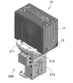
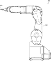
- FIG. It is a perspective view of the inversion apparatus 210 in the state in which the banknote storage container 10 was mounted based on this Embodiment. It is a perspective view of the inversion apparatus 210 of the state which the rotary table 211 raised based on this Embodiment. It is a perspective view of the inversion apparatus 210 in the state which the rotation table 211 rotated based on this Embodiment. It is a front view of the 1st arm 300 concerning this embodiment. It is a perspective view of the 1st arm 300 concerning this embodiment.
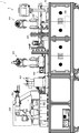
- the automatic banknote handling system 1 mainly includes a control device 100, a transport device 200, a first arm 300, a second arm 400, The banknote organizing device 500, the banknote organizing device 600, the third arm 700, the banding device 800, and the storage box 900 are provided.
- the transport device 200, the first arm 300, the second arm 400, the bill sorting device 500, the bill sorting device 600, the third arm 700, and the banding device. 800 and the storage box 900 are placed on the top of the table 50, and the control device 100 is stored under the table 50.
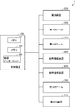
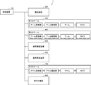
- the control device 100 includes a memory 120 for storing various programs and data, each part of the automatic banknote handling system 1, that is, a transport apparatus 200, a first arm 300, a second arm 400, and a banknote ordering apparatus 500.
- the third arm 700, the communication interface 160 that exchanges data with the banding device 800, and the like, the control device 100 is controlled according to a program, and each part of the automatic banknote handling system 1 is controlled via the communication interface 160.
- a CPU 110 or the like is installed.
- a bill storage container handling system 2 In the automatic bill handling system 1, elements relating to the conveyance, unlocking, opening, and taking out of bills of the bill storage container 10 are collectively referred to as a bill storage container handling system 2 or an unlocking system 2.
- the transport device 200 transports the banknote storage container 10 (see FIG. 5) based on a command from the control device 100 (step S102).
- the transport apparatus 200 transports the banknote storage container 10 brought from the outside of the room where the automatic banknote handling system 1 is arranged to the vicinity of the first arm 300.
- the transport apparatus 200 includes a first transport conveyor 201, a second transport conveyor 202, a reversing device 210, an RFID antenna 220, and a transfer device 230.
- the control device 100 identifies the surface having the keyhole 12, that is, the surface on the lid 11 side, based on the data from the RFID antenna 220 (step S104). Although details will be described later, in the present embodiment, an RFID tag is attached to the surface of the banknote storage container 10 that does not have the keyhole 12. When the RFID antenna 220 detects the RFID tag based on the signal from the RFID antenna 220, the control device 100 determines that the lid 11 and the keyhole 12 are on the opposite surface, and the banknote storage container 10 as it is. Is transferred to the transfer device 230.
- the transfer device 230 includes sliders 231 and 232 and transfers the banknote storage container 10 from the first transport conveyor 201 to the second transport conveyor 202.
- the control device 100 determines that the lid 11 and the keyhole 12 are on the surface on the RFID antenna 220 side, The banknote storage container 10 is rotated using the reversing device 210 so that the surface is on the first arm 300 side (step S106). And the control apparatus 100 delivers the banknote storage container 10 after rotation to the 2nd conveyance conveyor 202.
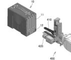
- the first arm 300 has a key 310 for unlocking the lid 11 of the banknote storage container 10. As will be described later, the first arm 300 moves the key 310 back and forth, right and left, up and down, and rotates the key 310 based on a command from the control device 100, thereby moving the key 310 to the bill storage container 10. Into the keyhole 12. The first arm 300 unlocks the banknote storage container 10 by rotating the key 310 based on a command from the control device 100 and opens the lid 11 as it is. More specifically, the control device 100 corrects the rotation angle of the key 310 (rotates the arm) using the vertical position data of the keyhole 12 and the rotation angle data of the keyhole 12 obtained from the camera, and then the keyhole. The first arm 300 is moved to the 12 position.
- the second arm 400 has a grip portion 410 for grasping a bill.
- the second arm 400 grabs the banknote in the banknote storage container 10 by moving the gripping part 410 back and forth, right and left, and up and down based on a command from the control device 100, takes out the banknote, and transfers the banknote to the banknote. Or placed on the tidy device 500.
- the control device 100 controls the first arm 300 to lock the banknote storage container 10.
- the control apparatus 100 controls the 2nd conveyance conveyor 202 of the conveying apparatus 200, and conveys the empty banknote storage container 10 to the exterior of a room.
- the camera 420 is attached to the second arm 400 in the vicinity of the grip portion 410. Then, the following control is executed. That is, the control device 100 moves the banknote storage container 10 to the front of the front of the first arm 300 using the transport device 200. The control apparatus 100 images the front of the banknote storage container 10 with the camera 420 of the second arm 400 (step S108). The control device 100 specifies the position of the keyhole 12 based on the image data (step S110). The control device 100 controls the first arm 300 to move the key 310 to the keyhole 12 and insert it. The control device 100 controls the first arm 300 to rotate the key 310 (step S112).
- the control device 100 controls the first arm 300 to open the cover of the banknote storage container 10 (step S114).
- the control device 100 controls the second arm 400 to put the grip portion 410 into the banknote storage container 10.
- the control device 100 controls the second arm 400 and sandwiches the banknote with the grip portion 410.
- the control device 100 controls the second arm 400 to draw out the banknote (step S116).
- the control apparatus 100 controls the 2nd arm 400, rotates the holding part 410 90 degree
- the control device 100 controls the second arm 400 to place the bill on the bill sorting device 500.
- the banknote sorting apparatus 500 sorts banknotes based on a command from the control apparatus 100. That is, the banknote sorting apparatus 500 aligns the positions of the ends of the banknote bundle (step S118). More specifically, in the present embodiment, the banknote sorting apparatus 500 is supported by a plate from the side so that the banknote does not fall down when the banknote set up vertically is placed by the second arm 400. To do. And the banknote sorting apparatus 500 aligns the position of the lower surface and side surface of the banknote stood
- the control device 100 controls the second arm 400 that has been waiting while the banknotes are in order to re-hold the banknotes in order.
- the control device 100 controls the second arm 400 to place the organized banknotes on the insertion port of the banknote sorting apparatus 600.
- the control device 100 controls the second arm 400 and pushes the banknote placed on the insertion slot into the back by the tip of the grip portion 410.
- the banknote organizing apparatus 600 discriminates each type of banknote delivered from the second arm 400, and stores it separately for each banknote type (step S120).
- the banknote sorting apparatus 600 may reject banknotes that have failed to be sorted.
- control device 100 controls third arm 700 to grip the banknote rejected by gripping unit 710.
- the control device 100 controls the second arm 400 and receives the banknote rejected from the third arm 700 by the grip portion 410.
- the control apparatus 100 mounts the said banknote in the insertion slot of the banknote rearrangement apparatus 600 again (step S120).
- the banknote sorting apparatus 600 displays the number of sheets sorted and stored for each ticket type when sorting banknotes.
- the banknote sorting apparatus 600 stops sorting when a predetermined number, for example, 100 sheets, is collected for each ticket type.
- a camera is also mounted on the third arm 700, and the control device 100 acquires the number of banknotes arranged for each ticket type from an image captured by the camera.
- the control device 100 controls the third arm 700 to grip the banknote by the grip portion 710 and receive it in the banding device 800 when a predetermined number of banknotes of any one of the bill types reaches a predetermined number. hand over.
- the banding device 800 winds the band around a bundle of a predetermined number of banknotes (step S124).
- the control device 100 controls the third arm 700 to grab a banknote wound with a band and put it into the storage box 900.
- the storage box 900 is divided for each ticket type, and the control device 100 controls the third arm 700 so that the banknote around which the band is wound corresponds to the ticket type. It puts in the storage box 900 (step S126).
- the banknotes of a plurality of types of stored banknotes are automatically set for each banknote type and predetermined from the state of the locked banknote storage container 10. Since it can be converted into a bundle of bundled banknotes for each number, it is possible to handle banknotes more safely and conveniently than before.
- the third arm 700 is equipped with a camera, and the control device 100 determines whether or not a predetermined number of banknotes are accumulated for each type of ticket based on the image from the camera. there were.
- the banknote sorting apparatus 600 may transmit to the control apparatus 100 data on the number of banknotes that have been sorted for each ticket type or a notification that a predetermined number of banknotes has been accumulated.
- the third arm 700 may not have a camera.
- the transport apparatus 200 includes a transport conveyor 201 on the input side of the banknote storage container 10, a transport conveyor 202 on the discharge side of the banknote storage container 10, a reversing device 210, a proximity sensor 221, an RFID antenna 220.
- the transport conveyors 201 and 202 transport the banknote storage container 10 in accordance with a command from the control device 100.
- the position of the banknote storage container 10 on the conveyors 201 and 202 is performed by a photoelectric sensor.
- the control apparatus 100 will control the conveyance conveyor 201 and will convey the banknote storage container 10. As shown in FIG. As shown in FIG. 9, the bill storage container 10 stops when it comes into contact with the guide 212 of the reversing device 210. In the present embodiment, when the proximity sensor 221 detects the presence of the banknote storage container 10, the proximity sensor 221 notifies the control device 100 accordingly. The control device 100 turns on the RFID antenna 220 to search for the RFID tag of the banknote storage container 10.
- the RFID tag 15 (see FIG. 12) is attached to the opposite surface of the lid 11 of the banknote storage container 10.
- the control device 100 controls the transport conveyor 201 to transport the banknote storage container 10 as it is and deliver it to the discharge-side transport conveyor 202.
- control device 100 rotates the rotary table 211 by 180 ° and then controls the transport conveyor 201 to transport the banknote storage container 10, Delivered to the conveyor 202.
- the banknote storage container 10 stops in contact with the guide 212 of the reversing device 210.
- the control device 100 drives the ascending cylinder 213 to raise the rotary table 211 and the bill storage container 10 as shown in FIG.
- the control device 100 drives the rotary cylinder 214 to rotate the rotary table 211 and the bill storage container 10 by 180 °.
- the control device 100 lowers the ascending cylinder 213 and lowers the rotary table 211 and the bill storage container 10 to the transport conveyor 201.
- control device 100 controls the conveyors 201 and 202 to move the banknote storage container 10 to the front surface of the first arm 300 or the second arm 400.
- the first arm 300 includes an arm main body 302 for controlling the position, angle, and posture of the key 310, and the key 310.
- the first arm 300 drives a motor or an actuator inside the arm main body 302 based on a command from the control device 100 to rotate or move the key 310 for the bill storage container 10 in six axial directions. can do.
- the second arm 400 includes an arm main body 402 for controlling the position, angle, and posture of the gripper 410, the gripper 410, and the camera 420.
- the second arm 400 drives a motor and an actuator inside the arm main body 402 based on a command from the control device 100, and includes a gripping portion 410 for gripping bills and a camera 420 for photographing the keyhole 12. It can be rotated or moved in the axial direction.
- the CPU 110 of the control device 100 controls the second arm 400 via the communication interface 160 to move the camera 420 to the front of the banknote storage container 10 as shown in FIG.
- the front of the banknote storage container 10 is photographed by (Step S202).
- the CPU 110 of the control device 100 reads the basic image of the keyhole 12 from the memory 120 (step S204).
- the CPU 110 specifies the position of the keyhole 12 by matching the image from the camera 420 with the basic image of the keyhole 12 (step S206).
- CPU 110 calculates the position of keyhole 12 with respect to the current position of key 310 based on the matching result (step S208).
- the CPU 110 moves the key 310 to the front of the keyhole 12 as shown in FIG. 20 by controlling the first arm 300 via the communication interface 160 (step S210).
- the CPU 110 controls the first arm 300 via the communication interface 160, thereby inserting the key 310 into the keyhole 12 (step S212) and rotating the key 310 in the unlocking direction as shown in FIG. (Step S214).
- CPU110 controls the 1st arm 300 via the communication interface 160, and as shown in FIG. 5, opens the key 310 and the lid
- CPU110 controls the 2nd arm 400 via the communication interface 160, and as shown in FIG. 22, after inserting the holding part 410 into the banknote storage container 10 and taking out a banknote (step S218), the said banknote Is transferred to the banknote sorting apparatus 500.
- the CPU 110 controls the first arm 300 via the communication interface 160, thereby closing the key 310 and the lid 11 of the bill storage container 10 (step S220).
- the CPU 110 controls the first arm 300 via the communication interface 160, thereby rotating the key 310 in the locking direction (step S222) and pulling out the key 310 from the key hole 12 of the banknote storage container 10 (step S224). .
- control device 100 controls the discharge-side transport conveyor 202 to move the locked empty banknote storage container 10 to the outside of the automatic banknote handling system 1.
- the banknote storage container handling system 2 automatically unlocks the banknote storage container 10, opens the cover 11 of the banknote storage container 10, and stores the banknotes in the banknote storage container 10. It can take out and the cover 11 of the banknote storage container 10 can be closed, and the banknote storage container 10 can be locked.
- the first arm 300 is mounted with one key 310.
- the automatic banknote handling system 1 and the banknote storage container handling system 2 can handle a plurality of types of keys. Good.
- the memory 120 of the control device 100 stores images of a plurality of types of keyholes corresponding to each of a plurality of types of keys.
- the CPU 110 compares the captured keyhole image with a plurality of types of keyhole images in the memory 120 to identify the keyhole type, the key type, and the keyhole position.
- the first arm 300 may be mounted so that a plurality of keys can be selected, or a plurality of keys may be placed in the vicinity of the first arm 300. 18, the CPU 110 exchanges the key 310 specified by controlling the first arm 300 via the communication interface 160. Then, the CPU 110 controls the first arm 300 via the communication interface 160 to move the identified key 310 to the front of the keyhole 12 as shown in FIG.
- the RFID tag 15 is attached to the opposite surface of the lid 11 of the banknote storage container 10.
- the RFID tag 15 is attached to the lid 11 of the banknote storage container 10, and the RFID tag 15 is attached.
- the antenna 220 may be disposed on the first arm 300 side.
- the RFID tag 15 may be attached to the opposite surface of the cover 11 of the banknote storage container 10 and the RFID antenna 220 may be disposed on the first arm 300 side.
- the control device 100 rotates the banknote storage container 10 and then advances it to the discharge-side transport conveyor 202.
- the control device 100 advances the banknote storage container 10 to the discharge-side transport conveyor 202 as it is without rotating.
- the RFID tag 15 may be attached to the surface of the lid 11 of the banknote storage container 10, and the RFID antenna 220 may be disposed on the side opposite to the first arm 300.
- the control device 100 rotates the banknote storage container 10 and then advances it to the discharge-side transport conveyor 202.
- the control device 100 advances the banknote storage container 10 to the discharge-side transport conveyor 202 as it is without rotating.
- the RFID tag 15 may be attached to both the surface of the lid 11 of the banknote storage container 10 and the opposite surface, and information for specifying the surface of the lid 11 or the keyhole 12 may be stored.
- the RFID tag 15 not only the RFID tag 15 but also a barcode or a specific image for identifying the surface of the lid 11 or the keyhole 12 is drawn on the upper surface or side surface of the banknote storage container 10, and the RFID antenna 220 can be used instead.
- the surface of the lid 11 or the keyhole 12 may be specified by an optical sensor or a camera.
- the RFID tag 15 not only the RFID tag 15, but also an uneven shape for identifying the surface of the lid 11 and the keyhole 12 is formed on the upper surface or side surface of the banknote storage container 10, and this shape is used as a contact sensor, proximity sensor, or image.
- the surface of the lid 11 or the keyhole 12 may be specified by detecting with a sensor or the like.
- the keyhole 12 was formed in the lid
- the keyhole 12 of the banknote storage container 10 is not limited to the form formed in the lid 11, and may be formed in a place other than the lid 11.
- the banknote storage container 10 is rotated by the reversing device 210 so that the lid 11 of the banknote storage container 10 faces the first arm 300.
- the control device 100 may move the key 310 of the first arm 300 to the surface of the keyhole 12 in accordance with the position of the surface of the keyhole 12 of the banknote storage container 10. That is, the form which moves the key 310 to the keyhole 12 across the banknote storage container 10 and the conveying apparatus 200 may be sufficient as the 1st arm 300.
- the 1st arm 300 may be arrange
- the role of each device may be played by another device, the role of one device may be shared by a plurality of devices, and the roles of a plurality of devices It may be carried by a single device.
- the role of the control device 100 may be played by the controller of the first arm 300 or the second arm 400.
- 18 may be executed by the CPU or memory of the camera 420, or the processing of step S208 or step S210 may be executed by the controller of the first arm 300.
- the camera 420 may be attached to the same first arm 300 as the key 310.
- the camera 420 may not move. That is, the camera 420 may be fixed to a support member placed on the table 50.
- an unlocking system 2 including a control device 100 for unlocking by inserting and rotating a key 310 into the keyhole 12 by control.
- the key 310 is a key for unlocking the banknote storage container 10 in which banknotes are stored.
- the control device 100 controls the first arm 300 after unlocking to open the cover of the banknote storage container 10, and controls the first arm 300 after taking out the banknote to lock the key 310 to rotate.
- control device 100 can refer to the image of the keyhole 12.
- the control device 100 specifies the position of the keyhole 12 based on the image acquired by the camera 420 and the image of the keyhole 12.
- control device 100 can refer to the images of the plurality of keyholes 12 corresponding to the plurality of keys 310, respectively.
- the control device 100 specifies the key 310 to be used for the keyhole 12 based on the image acquired by the camera 420.
- the unlocking system 2 further includes a second arm 400 to which the camera 420 is attached.
- the camera 420 is also provided on the first arm 300.
- the camera 420 is fixed.
Landscapes
- Physics & Mathematics (AREA)
- General Physics & Mathematics (AREA)
- Engineering & Computer Science (AREA)
- Human Computer Interaction (AREA)
- Robotics (AREA)
- Mechanical Engineering (AREA)
- Lock And Its Accessories (AREA)
- Pile Receivers (AREA)
- Manipulator (AREA)
Abstract
Description
<自動紙幣取扱いシステム1の全体構成>
図1から図3に示すように、本実施の形態にかかる自動紙幣取扱いシステム1は、主に、制御装置100と、搬送装置200と、第1のアーム300と、第2のアーム400と、紙幣整頓装置500と、紙幣整理装置600と、第3のアーム700と、帯付け装置800と、収納ボックス900とを有するものである。なお、本実施の形態においては、搬送装置200と、第1のアーム300と、第2のアーム400と、紙幣整頓装置500と、紙幣整理装置600と、第3のアーム700と、帯付け装置800と、収納ボックス900とが台50の上部に載置され、制御装置100が台50の下に収納される。
以下、図1~図4を参照して、本実施の形態にかかる自動紙幣取扱いシステム1の動作について説明する。
以下、本実施の形態にかかる紙幣格納容器取扱いシステム2の構成について説明する。
まず、搬送装置200について説明する。図6を参照して、搬送装置200は、紙幣格納容器10の投入側の搬送コンベア201と、紙幣格納容器10の排出側の搬送コンベア202と、反転装置210と、近接センサ221と、RFIDアンテナ220とを含む。
本実施の形態においては、図8に示すように、搬送コンベア201に紙幣格納容器10が載置されると、制御装置100が、搬送コンベア201を制御して紙幣格納容器10を搬送する。図9に示すように、紙幣格納容器10は、反転装置210のガイド212に当接すると停止する。本実施の形態においては、近接センサ221が、紙幣格納容器10の存在を検知すると、その旨を制御装置100に通知する。制御装置100は、RFIDアンテナ220をONして紙幣格納容器10のRFIDタグを探索させる。
次に、第1のアーム300の構成について説明する。図13および図14に示すように、第1のアーム300は、鍵310の位置や角度や姿勢を制御するためのアーム本体302と、鍵310とを有する。第1のアーム300は、制御装置100から指令に基づいて、アーム本体302内部のモータやアクチュエータを駆動させて、紙幣格納容器10用の鍵310を6軸方向に回動させたり、移動させたりすることができる。
次に、第2のアーム400の構成について説明する。図15~図17に示すように、第2のアーム400は、把持部410の位置や角度や姿勢を制御するためのアーム本体402と、把持部410と、カメラ420とを有する。第2のアーム400は、制御装置100から指令に基づいて、アーム本体402内部のモータやアクチュエータを駆動させて、紙幣を掴むための把持部410や、鍵穴12を撮影するためのカメラ420を6軸方向に回動させたり、移動させたりすることができる。
次に、図18を参照しながら、制御装置100による第1のアーム300と第2のアーム400の制御について説明する。本実施の形態においては、排出側の搬送コンベア202によって紙幣格納容器10が第1のアーム300または第2のアーム400の正面まで搬送されると、制御装置100が以下の処理を実行する。
上記の実施の形態においては、第1のアーム300が1つの鍵310を搭載するものであったが、自動紙幣取扱いシステム1および紙幣格納容器取扱いシステム2は、複数種類の鍵に対応できてもよい。
上記の実施の形態においては、RFIDタグ15が紙幣格納容器10の蓋11の反対面に取り付けられるものであったが、RFIDタグ15が紙幣格納容器10の蓋11の方に取り付けられて、RFIDアンテナ220が第1のアーム300側に配置されてもよい。
また、上記の実施の形態においては、紙幣格納容器10の蓋11に鍵穴12が形成されるものであった。しかしながら、紙幣格納容器10の鍵穴12は、蓋11に形成にされる形態には限られず、蓋11以外の個所に形成されてもよい。
また、上記の実施の形態においては、紙幣格納容器10の蓋11が第1のアーム300に対向するように、紙幣格納容器10を反転装置210によって回動するものであった。しかしながら、紙幣格納容器10の鍵穴12の面の位置に合わせて、制御装置100が、第1のアーム300の鍵310を、鍵穴12の面まで移動させてもよい。すなわち、第1のアーム300が、紙幣格納容器10や搬送装置200を跨いで、鍵310を鍵穴12まで移動させる形態であってもよい。
上記の実施の形態の構成に限らず、各装置の役割が別の装置によって担われてもよいし、1つの装置の役割が複数の装置によって分担されてもよいし、複数の装置の役割が1つの装置によって担われてもよい。たとえば、図23に示すように、制御装置100の役割が、第1のアーム300や第2のアーム400のコントローラによって担われてもよい。そして、図18のステップS204やステップS206の処理は、カメラ420のCPUやメモリが実行してもよいし、ステップS208やステップS210の処理は第1のアーム300のコントローラが実行してもよい。
また、上記の実施の形態においては、カメラ420が第2のアーム400に取り付けられるものであった。しかしながら、カメラ420は、把持部410とは別の第3のアームに取り付けられてもよい。
上記の実施の形態においては、カメラ420と、1または複数の鍵310が取り付けられた第1のアーム300と、カメラ420から画像に基づいて鍵穴12の位置を特定し、第1のアーム300を制御することによって鍵穴12に鍵310を挿入し回動させることによって開錠するための制御装置100と、を備える開錠システム2が提供される。
2 :紙幣格納容器取扱いシステム(開錠システム)
10 :紙幣格納容器
11 :蓋
12 :鍵穴
15 :RFIDタグ
50 :台
100 :制御装置
110 :CPU
120 :メモリ
160 :通信インターフェイス
200 :搬送装置
201 :第1の搬送コンベア
202 :第2の搬送コンベア
210 :反転装置
211 :回転テーブル
212 :ガイド
213 :上昇シリンダ
214 :回転シリンダ
215 :ガイドシリンダ
220 :RFIDアンテナ
221 :近接センサ
230 :移載装置
231 :スライド
232 :スライド
300 :第1のアーム
302 :アーム本体
310 :鍵
400 :第2のアーム
402 :アーム本体
410 :把持部
420 :カメラ
500 :紙幣整頓装置
600 :紙幣整理装置
700 :第3のアーム
710 :把持部
800 :帯付け装置
900 :収納ボックス
Claims (7)
- カメラと、
1または複数の鍵が取り付けられた第1のアームと、
前記カメラから画像に基づいて鍵穴の位置を特定し、前記第1のアームを制御することによって前記鍵穴に前記鍵を挿入し回動させることによって開錠するための制御装置と、を備える開錠システム。 - 前記鍵は、紙幣が格納される紙幣格納容器を開錠するための鍵であって、
前記制御装置は、前記開錠後に前記第1のアームを制御して前記紙幣格納容器の蓋を開け、紙幣取り出し後に前記第1のアームを制御することによって前記鍵を回動させることによって施錠する、請求項1に記載の開錠システム。 - 前記制御装置は、鍵穴の画像を参照可能であって、
前記制御装置は、前記カメラが取得した画像と前記鍵穴の画像とに基づいて前記鍵穴の位置を特定する、請求項1または2に記載の開錠システム。 - 前記制御装置は、複数の鍵それぞれに対応する複数の鍵穴の画像を参照可能であって、
前記制御装置は、前記カメラが取得した画像に基づいて、鍵穴に対して使用すべき鍵を特定する、請求項1から3のいずれか1項に記載の開錠システム。 - 前記カメラが取り付けられる、第2のアームをさらに備える、請求項1から4のいずれか1項に記載の開錠システム。
- 前記カメラも前記第1のアームに設けられる、請求項1から4のいずれか1項に記載の開錠システム。
- 前記カメラが固定されている、請求項1から4のいずれか1項に記載の開錠システム。
Priority Applications (5)
| Application Number | Priority Date | Filing Date | Title |
|---|---|---|---|
| CN201980008510.4A CN111602183B (zh) | 2018-05-22 | 2019-04-16 | 解锁系统 |
| CN202210172880.5A CN114530012A (zh) | 2018-05-22 | 2019-04-16 | 解锁系统及解锁方法 |
| CA3087704A CA3087704C (en) | 2018-05-22 | 2019-04-16 | Unlocking system |
| EP19806638.3A EP3799000A4 (en) | 2018-05-22 | 2019-04-16 | Unlocking system |
| AU2019273976A AU2019273976B2 (en) | 2018-05-22 | 2019-04-16 | Unlocking system |
Applications Claiming Priority (2)
| Application Number | Priority Date | Filing Date | Title |
|---|---|---|---|
| JP2018-097807 | 2018-05-22 | ||
| JP2018097807A JP6647596B2 (ja) | 2018-05-22 | 2018-05-22 | 開錠システム |
Publications (1)
| Publication Number | Publication Date |
|---|---|
| WO2019225218A1 true WO2019225218A1 (ja) | 2019-11-28 |
Family
ID=68616434
Family Applications (1)
| Application Number | Title | Priority Date | Filing Date |
|---|---|---|---|
| PCT/JP2019/016235 Ceased WO2019225218A1 (ja) | 2018-05-22 | 2019-04-16 | 開錠システム |
Country Status (6)
| Country | Link |
|---|---|
| EP (1) | EP3799000A4 (ja) |
| JP (1) | JP6647596B2 (ja) |
| CN (2) | CN114530012A (ja) |
| AU (1) | AU2019273976B2 (ja) |
| CA (1) | CA3087704C (ja) |
| WO (1) | WO2019225218A1 (ja) |
Cited By (1)
| Publication number | Priority date | Publication date | Assignee | Title |
|---|---|---|---|---|
| CN113898251A (zh) * | 2021-09-29 | 2022-01-07 | 珠海优特电力科技股份有限公司 | 机器人系统的闭锁方法和解锁方法以及机器人系统 |
Families Citing this family (3)
| Publication number | Priority date | Publication date | Assignee | Title |
|---|---|---|---|---|
| US10755522B1 (en) * | 2019-05-10 | 2020-08-25 | Jcm American Corporation | Drop cart with cashbox data reader array and autonomous drop cart processing system for automated casino accounting |
| JP7190466B2 (ja) | 2020-09-04 | 2022-12-15 | 日本金銭機械株式会社 | 施解錠装置 |
| CN113898252B (zh) * | 2021-09-29 | 2022-11-18 | 珠海优特电力科技股份有限公司 | 机器人及其对机柜锁的解闭锁方法以及机柜锁 |
Citations (4)
| Publication number | Priority date | Publication date | Assignee | Title |
|---|---|---|---|---|
| JPS6292095A (ja) | 1985-10-18 | 1987-04-27 | 日本電気株式会社 | 関節型ロボツト組込現金処理装置 |
| JP2015085497A (ja) * | 2013-11-01 | 2015-05-07 | セイコーエプソン株式会社 | ロボット、ロボットシステムおよび制御装置 |
| JP2016031619A (ja) | 2014-07-28 | 2016-03-07 | グローリー株式会社 | 収納作業装置、有価媒体収納システム及び収納作業方法 |
| JP2016224664A (ja) | 2015-05-29 | 2016-12-28 | グローリー株式会社 | 有価媒体処理システム及び有価媒体処理方法 |
Family Cites Families (13)
| Publication number | Priority date | Publication date | Assignee | Title |
|---|---|---|---|---|
| ES2393068T3 (es) * | 2003-03-10 | 2012-12-18 | Diebold, Incorporated | Sistema y método de aceptación de depósito de máquina bancaria automática de distribución de efectivo |
| CN2864011Y (zh) * | 2006-01-19 | 2007-01-31 | 深圳市亚略特生物识别科技有限公司 | 指纹锁 |
| CN101787824B (zh) * | 2010-01-28 | 2013-04-03 | 南京信息工程大学 | 智能防盗锁系统 |
| CN102635324B (zh) * | 2011-06-06 | 2015-04-22 | 黄江平 | 密匙孔控空转防盗锁及钥匙 |
| JP5788733B2 (ja) * | 2011-08-09 | 2015-10-07 | グローリー株式会社 | 貨幣処理装置、貨幣管理システム、及び貨幣管理方法 |
| JP5375909B2 (ja) * | 2011-09-20 | 2013-12-25 | 沖電気工業株式会社 | 施錠装置及び現金自動取引装置 |
| JP5928109B2 (ja) * | 2012-04-09 | 2016-06-01 | 沖電気工業株式会社 | 現金処理装置、及び、当該現金処理装置に用いるユニットロック機構 |
| JP6265004B2 (ja) * | 2014-03-31 | 2018-01-24 | 沖電気工業株式会社 | 入力キー配置構造および自動取引装置 |
| CN105427413A (zh) * | 2015-11-02 | 2016-03-23 | 北京奇虎科技有限公司 | 智能开锁方法和智能锁具 |
| CN106934264A (zh) * | 2015-12-31 | 2017-07-07 | 深圳先进技术研究院 | 一种智能解锁方法、装置和锁设备 |
| JP6440263B2 (ja) * | 2016-05-26 | 2018-12-19 | 株式会社日本パープル | 機密性を有する廃棄物の処理方法及び処理設備 |
| CN107092926A (zh) * | 2017-03-30 | 2017-08-25 | 哈尔滨工程大学 | 基于深度学习的服务机器人物体识别算法 |
| CN207847305U (zh) * | 2017-06-05 | 2018-09-11 | 浙江维融电子科技股份有限公司 | 一种应用于安全钱箱的安全锁组件 |
-
2018
- 2018-05-22 JP JP2018097807A patent/JP6647596B2/ja active Active
-
2019
- 2019-04-16 CN CN202210172880.5A patent/CN114530012A/zh active Pending
- 2019-04-16 CN CN201980008510.4A patent/CN111602183B/zh active Active
- 2019-04-16 EP EP19806638.3A patent/EP3799000A4/en not_active Withdrawn
- 2019-04-16 AU AU2019273976A patent/AU2019273976B2/en active Active
- 2019-04-16 WO PCT/JP2019/016235 patent/WO2019225218A1/ja not_active Ceased
- 2019-04-16 CA CA3087704A patent/CA3087704C/en active Active
Patent Citations (4)
| Publication number | Priority date | Publication date | Assignee | Title |
|---|---|---|---|---|
| JPS6292095A (ja) | 1985-10-18 | 1987-04-27 | 日本電気株式会社 | 関節型ロボツト組込現金処理装置 |
| JP2015085497A (ja) * | 2013-11-01 | 2015-05-07 | セイコーエプソン株式会社 | ロボット、ロボットシステムおよび制御装置 |
| JP2016031619A (ja) | 2014-07-28 | 2016-03-07 | グローリー株式会社 | 収納作業装置、有価媒体収納システム及び収納作業方法 |
| JP2016224664A (ja) | 2015-05-29 | 2016-12-28 | グローリー株式会社 | 有価媒体処理システム及び有価媒体処理方法 |
Cited By (1)
| Publication number | Priority date | Publication date | Assignee | Title |
|---|---|---|---|---|
| CN113898251A (zh) * | 2021-09-29 | 2022-01-07 | 珠海优特电力科技股份有限公司 | 机器人系统的闭锁方法和解锁方法以及机器人系统 |
Also Published As
| Publication number | Publication date |
|---|---|
| CN114530012A (zh) | 2022-05-24 |
| EP3799000A4 (en) | 2022-03-02 |
| CN111602183B (zh) | 2022-03-18 |
| CA3087704C (en) | 2023-03-28 |
| CA3087704A1 (en) | 2019-11-28 |
| AU2019273976B2 (en) | 2021-04-08 |
| EP3799000A1 (en) | 2021-03-31 |
| JP6647596B2 (ja) | 2020-02-14 |
| AU2019273976A1 (en) | 2020-07-30 |
| CN111602183A (zh) | 2020-08-28 |
| JP2019204205A (ja) | 2019-11-28 |
Similar Documents
| Publication | Publication Date | Title |
|---|---|---|
| JP6617314B2 (ja) | 自動紙幣取扱いシステム | |
| JP6965333B2 (ja) | 開錠システムおよび開錠方法 | |
| WO2019225218A1 (ja) | 開錠システム | |
| WO2019225217A1 (ja) | 紙幣格納容器取扱いシステム | |
| US12518585B2 (en) | Bill handling system | |
| CN113692607A (zh) | 自动纸币处理系统 | |
| JP6908673B2 (ja) | 自動紙幣取扱いシステムおよび自動紙幣取扱い方法 | |
| JP6952252B2 (ja) | 紙幣格納容器取扱いシステムおよび紙幣格納容器の開錠方法 | |
| CN113692606A (zh) | 自动纸币处理系统以及纸币的自动处理方法 | |
| JP6601885B1 (ja) | 紙幣整頓装置 | |
| HK40036625B (en) | Unlocking system | |
| HK40036625A (en) | Unlocking system | |
| HK40036626B (zh) | 纸币存放容器处理系统 | |
| HK40036626A (en) | Banknote storage container handling system | |
| HK40036208A (en) | Automatic banknote handling system |
Legal Events
| Date | Code | Title | Description |
|---|---|---|---|
| 121 | Ep: the epo has been informed by wipo that ep was designated in this application |
Ref document number: 19806638 Country of ref document: EP Kind code of ref document: A1 |
|
| ENP | Entry into the national phase |
Ref document number: 3087704 Country of ref document: CA |
|
| ENP | Entry into the national phase |
Ref document number: 2019273976 Country of ref document: AU Date of ref document: 20190416 Kind code of ref document: A |
|
| NENP | Non-entry into the national phase |
Ref country code: DE |
|
| ENP | Entry into the national phase |
Ref document number: 2019806638 Country of ref document: EP Effective date: 20201222 |