WO2019225573A1 - 元素分析装置及び元素分析方法 - Google Patents
元素分析装置及び元素分析方法 Download PDFInfo
- Publication number
- WO2019225573A1 WO2019225573A1 PCT/JP2019/020032 JP2019020032W WO2019225573A1 WO 2019225573 A1 WO2019225573 A1 WO 2019225573A1 JP 2019020032 W JP2019020032 W JP 2019020032W WO 2019225573 A1 WO2019225573 A1 WO 2019225573A1
- Authority
- WO
- WIPO (PCT)
- Prior art keywords
- component
- gas
- sample
- heating furnace
- mass spectrometer
- Prior art date
- Legal status (The legal status is an assumption and is not a legal conclusion. Google has not performed a legal analysis and makes no representation as to the accuracy of the status listed.)
- Ceased
Links
Images


Classifications
-
- G—PHYSICS
- G01—MEASURING; TESTING
- G01N—INVESTIGATING OR ANALYSING MATERIALS BY DETERMINING THEIR CHEMICAL OR PHYSICAL PROPERTIES
- G01N31/00—Investigating or analysing non-biological materials by the use of the chemical methods specified in the subgroup; Apparatus specially adapted for such methods
- G01N31/12—Investigating or analysing non-biological materials by the use of the chemical methods specified in the subgroup; Apparatus specially adapted for such methods using combustion
-
- G—PHYSICS
- G01—MEASURING; TESTING
- G01N—INVESTIGATING OR ANALYSING MATERIALS BY DETERMINING THEIR CHEMICAL OR PHYSICAL PROPERTIES
- G01N21/00—Investigating or analysing materials by the use of optical means, i.e. using sub-millimetre waves, infrared, visible or ultraviolet light
- G01N21/17—Systems in which incident light is modified in accordance with the properties of the material investigated
- G01N21/25—Colour; Spectral properties, i.e. comparison of effect of material on the light at two or more different wavelengths or wavelength bands
- G01N21/31—Investigating relative effect of material at wavelengths characteristic of specific elements or molecules, e.g. atomic absorption spectrometry
-
- G—PHYSICS
- G01—MEASURING; TESTING
- G01N—INVESTIGATING OR ANALYSING MATERIALS BY DETERMINING THEIR CHEMICAL OR PHYSICAL PROPERTIES
- G01N27/00—Investigating or analysing materials by the use of electric, electrochemical, or magnetic means
- G01N27/62—Investigating or analysing materials by the use of electric, electrochemical, or magnetic means by investigating the ionisation of gases, e.g. aerosols; by investigating electric discharges, e.g. emission of cathode
- G01N27/622—Ion mobility spectrometry
- G01N27/623—Ion mobility spectrometry combined with mass spectrometry
-
- G—PHYSICS
- G01—MEASURING; TESTING
- G01N—INVESTIGATING OR ANALYSING MATERIALS BY DETERMINING THEIR CHEMICAL OR PHYSICAL PROPERTIES
- G01N31/00—Investigating or analysing non-biological materials by the use of the chemical methods specified in the subgroup; Apparatus specially adapted for such methods
- G01N31/22—Investigating or analysing non-biological materials by the use of the chemical methods specified in the subgroup; Apparatus specially adapted for such methods using chemical indicators
- G01N31/223—Investigating or analysing non-biological materials by the use of the chemical methods specified in the subgroup; Apparatus specially adapted for such methods using chemical indicators for investigating presence of specific gases or aerosols
-
- G—PHYSICS
- G01—MEASURING; TESTING
- G01N—INVESTIGATING OR ANALYSING MATERIALS BY DETERMINING THEIR CHEMICAL OR PHYSICAL PROPERTIES
- G01N33/00—Investigating or analysing materials by specific methods not covered by groups G01N1/00 - G01N31/00
- G01N33/0004—Gaseous mixtures, e.g. polluted air
- G01N33/0009—General constructional details of gas analysers, e.g. portable test equipment
- G01N33/0027—General constructional details of gas analysers, e.g. portable test equipment concerning the detector
- G01N33/0036—General constructional details of gas analysers, e.g. portable test equipment concerning the detector specially adapted to detect a particular component
- G01N33/005—H2
-
- H—ELECTRICITY
- H01—ELECTRIC ELEMENTS
- H01J—ELECTRIC DISCHARGE TUBES OR DISCHARGE LAMPS
- H01J49/00—Particle spectrometers or separator tubes
- H01J49/02—Details
- H01J49/04—Arrangements for introducing or extracting samples to be analysed, e.g. vacuum locks; Arrangements for external adjustment of electron- or ion-optical components
- H01J49/0468—Arrangements for introducing or extracting samples to be analysed, e.g. vacuum locks; Arrangements for external adjustment of electron- or ion-optical components with means for heating or cooling the sample
-
- H—ELECTRICITY
- H01—ELECTRIC ELEMENTS
- H01J—ELECTRIC DISCHARGE TUBES OR DISCHARGE LAMPS
- H01J49/00—Particle spectrometers or separator tubes
- H01J49/26—Mass spectrometers or separator tubes
-
- G—PHYSICS
- G01—MEASURING; TESTING
- G01N—INVESTIGATING OR ANALYSING MATERIALS BY DETERMINING THEIR CHEMICAL OR PHYSICAL PROPERTIES
- G01N33/00—Investigating or analysing materials by specific methods not covered by groups G01N1/00 - G01N31/00
- G01N33/0004—Gaseous mixtures, e.g. polluted air
- G01N33/0009—General constructional details of gas analysers, e.g. portable test equipment
- G01N33/0011—Sample conditioning
- G01N33/0013—Sample conditioning by a chemical reaction
-
- G—PHYSICS
- G01—MEASURING; TESTING
- G01N—INVESTIGATING OR ANALYSING MATERIALS BY DETERMINING THEIR CHEMICAL OR PHYSICAL PROPERTIES
- G01N33/00—Investigating or analysing materials by specific methods not covered by groups G01N1/00 - G01N31/00
- G01N33/20—Metals
- G01N33/202—Constituents thereof
- G01N33/2022—Non-metallic constituents
- G01N33/2025—Gaseous constituents
Definitions
- the present invention relates to an elemental analysis apparatus and an elemental analysis method.
- a crucible containing a sample is heated while introducing a carrier gas, and at least a part of the sample is vaporized to generate a sample gas.
- Some include a heating furnace derived as a mixed gas with a carrier gas, and a mass spectrometer that quantitatively analyzes at least one element contained in a sample gas in the mixed gas derived from the heating furnace.
- the H element contained as the H 2 component in the mixed gas is quantitatively analyzed as the H element contained in the sample gas.
- the mass spectrometer cannot detect the H 2 component having a small mass number with high sensitivity, and as a result, there is a problem in that the H element contained in the sample gas cannot be quantitatively analyzed with high accuracy. there were.
- the main object of the present invention is to obtain an element analyzer capable of quantitatively analyzing H element contained in a sample gas with high accuracy.
- the elemental analyzer heats a crucible containing a sample while introducing a carrier gas, vaporizes at least a part of the sample to generate a sample gas containing H element,
- a heating furnace derived as a mixed gas with the carrier gas; and a mass spectrometer for quantitatively analyzing at least one element contained in the sample gas in the mixed gas derived from the heating furnace,
- the meter is characterized in that the H element contained as the H 2 O component in the mixed gas is quantitatively analyzed as the H element contained in the sample gas.
- the H element in order to quantitatively analyze the H element contained in the sample gas, the H element is introduced into the mass spectrometer as an H 2 O component having a large mass number.
- the contained elements can be detected with high sensitivity.
- H element contained in the sample gas can be quantitatively analyzed with high accuracy.
- the apparatus further includes an oxidation unit installed between the heating furnace and the mass spectrometer, and the heating furnace generates a sample gas containing H element as an H-containing component, and includes the H-containing component.
- a mixed gas is derived, and the oxidation unit oxidizes the H-containing component in the mixed gas to generate a H 2 O component, and the mass spectrometer is in the mixed gas after oxidation.
- the H element contained as the H 2 O component may be quantitatively analyzed as the H element contained in the sample gas.
- the heating furnace generates a sample gas containing the H element as an H-containing component and a plurality of other elements other than the H element as different other element-containing components, and the H-containing component and the plurality of other elements.
- a mixed gas containing an element-containing component wherein the oxidation unit oxidizes the H-containing component in the mixed gas to generate an H 2 O component, and the plurality of other components in the mixed gas Among the element-containing components, at least one of two other element-containing components having a mass number difference of 3 or less is oxidized, and the mass spectrometer is used as the H 2 O component in the mixed gas after oxidation.
- the H element contained is quantitatively analyzed as the H element contained in the sample gas, and other elements other than the H element contained as the other element-containing component in the mixed gas after oxidation are included in the sample gas. What is necessary is just to comprise so that a quantitative analysis may be carried out as an element.
- the difference in mass number after oxidation of the two other element-containing components is Greater than 3.
- the difference in mass number between the two other element-containing components having the closest mass numbers contained in the mixed gas after oxidation becomes larger than 3.
- He gas may be used as a carrier gas for this type of elemental analyzer.
- Ar gas may be used as a carrier gas for this type of elemental analyzer.
- the Ar atom has a relatively large molecular diameter, this causes the ionization of components including the analysis target element in the mass spectrometer.
- the He atom has a relatively small molecular diameter, it does not prevent ionization of components including the analysis target element in the mass spectrometer.
- He gas can set the chamber pressure higher than Ar gas. Therefore, by using He gas as the carrier gas, components including the analysis target element are efficiently ionized in the mass spectrometer. Thereby, it becomes possible to detect more ions of the component including the analysis target element in the mass spectrometer, and as a result, the H element contained in the sample gas can be quantitatively analyzed with high accuracy.
- the quadrupole mass spectrometer when using a quadrupole mass spectrometer as the mass spectrometer, includes a calculation unit, and the calculation unit introduces the carrier gas into the heating furnace, The crucible in which the sample is not charged is heated by the heating furnace, the carrier gas derived from the heating furnace is introduced into the quadrupole mass spectrometer, and reference data indicating a change in signal intensity with time is obtained.
- a measurement data creation unit that introduces a measurement data showing a change in signal intensity with time by introducing it into a quadrupole mass spectrometer, and includes an element contained in the sample gas in the mixed gas in the measurement data
- a peak time zone identifying unit that identifies a peak time zone in which a signal strength peak corresponding to a minute is detected, the reference data, and a time at which the signal strength in the reference data is not an extreme value, and the peak
- the correction value calculation unit that calculates the area of the portion surrounded by the straight line connecting the start point and the end point of the predetermined time zone determined to include the time zone, the sample based on the measurement data and the correction value What is necessary is just to comprise so that the analysis part which carries out the quantitative analysis of the element contained in
- the elements contained in the sample gas are quantitatively analyzed by correcting the numerical values obtained from the measurement data with the correction values obtained from the reference data.
- the correction value is surrounded by the reference data and a straight line connecting the start point and the end point of the predetermined time zone that does not include the time when the signal intensity in the reference data is an extreme value and includes the peak time zone. If the area of the portion to be used is adopted, the lower limit for quantitative analysis is extended, and this enables quantitative analysis over a wider range.
- the element analyzer when quantitative analysis of the elements contained in the sample gas is performed by the element analyzer, the inside of the chamber to which the mass spectrometer is connected is maintained at a pressure close to vacuum. It was discovered that there is a pressure that can be detected with high sensitivity for each element. Therefore, the elemental analyzer is installed on the downstream side of the heating furnace, and the chamber to which the mass spectrometer is connected and the pressure in the chamber can be adjusted according to the element to be quantitatively analyzed by the mass spectrometer. You may make it further provide the pressure regulation mechanism comprised in this way.
- the pressure regulating mechanism includes a valve installed between the heating furnace and the chamber, and an exhaust pump installed on the downstream side of the chamber, and based on the opening of the valve
- the pressure sensor which measures the pressure in the said chamber is further provided, and the pressure value measured by the said pressure sensor is the said mass spectrometry.
- the pressure control part which controls so that it may approach the preset pressure predetermined according to the element quantitatively analyzed with a meter.
- the set pressure is preferably 1.0 Pa or more, and more preferably 1.0 Pa or more and 3.5 Pa or less.
- the elemental analysis method according to the present invention is an elemental analysis method for quantitatively analyzing elements contained in a sample gas generated by vaporizing a sample, and the crucible containing the sample is introduced while introducing the carrier gas into the heating furnace. Heat, vaporize at least part of the sample to generate a sample gas containing H element, and use H element in the mixed gas of the sample gas and the carrier gas derived from the heating furnace as an H 2 O component This is introduced into a mass spectrometer, and H element contained as an H 2 O component in the mixed gas is quantitatively analyzed by the mass spectrometer.
- the carrier gas derived from the heating furnace is subjected to the quadrupole mass spectrometry.
- the reference data indicating the change over time of the signal intensity is created by introducing into the meter, and while the carrier gas is being introduced into the heating furnace, the crucible in which the sample has been charged is heated by the heating furnace, and the heating furnace.
- the mixed gas derived from is introduced into the quadrupole mass spectrometer to create measurement data indicating changes in signal intensity over time, and includes elements contained in the sample gas in the mixed gas in the measurement data
- a peak time zone in which a peak of the signal intensity corresponding to the component is detected does not include the reference data and a time when the signal intensity in the reference data is an extreme value, and
- the area of the portion surrounded by the straight line connecting the start point and end point of the predetermined time period determined to include the peak time period is calculated as a correction value, and is included
- the H element contained in the sample gas can be quantitatively analyzed with high accuracy.
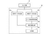
- FIG. 1 is a schematic diagram illustrating an overall configuration of an elemental analyzer according to Embodiment 1.
- FIG. It is a block diagram which shows the calculating part in the quadrupole mass spectrometer of the elemental analyzer which concerns on the same embodiment. It is a graph which shows the reference data and measurement data which were obtained by the analysis operation of the elemental analysis device concerning the embodiment. It is a graph which expands and shows the peak vicinity of the measurement data obtained by the analysis operation
- the elemental analysis apparatus of the present embodiment heats and melts a sample such as steel or ceramics put into a crucible, extracts elements contained in the sample gas generated at that time, and performs quantitative analysis.
- the elemental analyzer 100 is connected to a heating furnace 10, an upstream line L1 extending upstream from the heating furnace 10, and a starting end of the upstream line L1.
- a carrier gas supplier 20 a downstream line L2 extending downstream from the heating furnace 10, a chamber 30 connected to the end of the downstream line L2, a quadrupole mass spectrometer 40 connected to the chamber 30, and a chamber
- a pressure adjusting mechanism 50 that adjusts the pressure within 30.
- the heating furnace 10 is a so-called impulse furnace and houses a crucible 11 into which a sample is put. Note that the heating furnace 10 generates Joule heat by supplying an impulse current to the crucible 11 and thereby vaporizing at least a part of the sample put in the crucible 11 to generate a sample gas.
- a graphite crucible can be used as the crucible 11 as the crucible 11.
- the upstream line L1 introduces the carrier gas supplied from the carrier gas supplier 20 to the heating furnace 10.
- the upstream line L1 is provided with a purifier 60 for purifying the carrier gas in the middle thereof.
- the carrier gas it is preferable to use an inert gas, and in particular, to use He gas.
- the downstream line L2 introduces a mixed gas of the sample gas and the carrier gas derived from the heating furnace 10 into the chamber 30.
- the 1st exhaust line L3 branched and extended from the middle is connected to the downstream line L2.
- the end of the first exhaust line L3 is open to the atmosphere.
- the chamber 30 has a structure with four ports.
- the four ports are connected to a downstream line L3, a quadrupole mass spectrometer 40, a pressure sensor P for measuring the pressure in the chamber, and a second exhaust line L4.
- the quadrupole mass spectrometer 40 quantitatively analyzes an element (hereinafter also referred to as an analysis target element) contained in a sample gas in a mixed gas. Specifically, the quadrupole mass spectrometer 40 ionizes components including the element to be analyzed, refers to a sensor unit 41 that detects the ions, and changes with time in the signal intensity detected by the sensor unit 41. And an arithmetic unit 42 that quantitatively analyzes the element to be analyzed.
- the signal strength is, for example, current strength, electromagnetic strength, or the like.
- the quadrupole mass spectrometer 40 is connected to the chamber 30 so that the sensor unit 41 is inserted into the port.
- the calculation unit 42 is a so-called computer including a CPU, a memory, an A / D / D / A converter, and the like, and executes a program stored in the memory to realize a function of quantitatively analyzing an analysis target element. It is configured as follows.
- the calculation unit 42 includes a reference data creation unit 42a that creates reference data, a measurement data creation unit 42b that creates measurement data, and a peak time zone specification unit 42c that specifies a peak time zone in the measurement data.
- a correction value calculation unit 42d that calculates a correction value based on the reference data and the peak time zone, and an analysis unit 42e that quantitatively analyzes the analysis target element based on the reference data and the correction value.
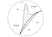
- the reference data creation unit 42a creates reference data through the following steps. More specifically, first, the crucible 11 in a state where a sample is not charged is heated by the heating furnace 10 while introducing the carrier gas from the upstream line L1 to the heating furnace 10. Next, the carrier gas led out from the heating furnace 10 in that state to the downstream line L ⁇ b> 2 is introduced into the quadrupole mass spectrometer 40. Then, the reference data creation unit 42a creates reference data D1 (data indicated by a solid line in FIG. 3) in which the change over time of the signal intensity detected by introducing the carrier gas into the quadrupole mass spectrometer 40 is plotted. To do.
- the measurement data creation unit 42b creates measurement data through the following steps. More specifically, first, the crucible 11 in which the sample has been charged is heated by the heating furnace 10 while introducing the carrier gas from the upstream line L1 to the heating furnace 10. Next, the mixed gas led out from the heating furnace 10 in that state to the downstream line L ⁇ b> 2 is introduced into the quadrupole mass spectrometer 40. Then, the measurement data creation unit 42b creates measurement data D2 (data indicated by a dotted line in FIG. 3) in which the change over time of the signal intensity detected by introducing the mixed gas into the quadrupole mass spectrometer 40 is plotted. To do.
- the peak time zone specifying unit 42c specifies the peak time zone Z in which the signal intensity peak P corresponding to the component including the analysis target element in the measurement data D2 is detected.
- the peak time zone Z is defined as a time zone between the start point SP and the end point EP, with the start time of the peak P as the start point SP, the end time as the end point EP.
- the starting point SP of the peak time zone Z is a transition point at which the tangent slope of the measurement data D2 changes from a state where it coincides with a slope of the tangent line passing through the reference data D1 at the rising edge of the peak P.
- the end point EP of the peak time zone Z is a transition point at which the slope of the tangent line of the measurement data D2 changes from a state that does not coincide with the slope of the tangent line that passes through the reference data D1 at the fall of the peak P. It's time. Therefore, the peak time zone Z is a time zone before and after the time when the signal intensity at the peak P is maximum (maximum value).
- the correction value calculation unit 42d does not include the reference data D1 and the time when the signal intensity in the reference data D1 is an extreme value and includes the peak time zone Z, and the start point SP1 of the predetermined time zone Z ′. And the area surrounded by the straight line l1 connecting the end points EP1 (the portion indicated by the diagonal line in FIG. 4) is calculated as a correction value.
- the predetermined time zone Z ′ is set to coincide with the peak time zone Z, but the predetermined time zone Z ′ may be set to include the peak time zone Z.
- the analysis unit 42e quantitatively analyzes the analysis target element based on the measurement data D2 and the correction value. Specifically, the analysis unit 42e is a portion surrounded by the measurement data D2 and a straight line l2 connecting the start point SP2 and the end point EP2 of the predetermined time zone Z in the measurement data D2 (portion indicated by a solid diagonal line in FIG. 4). And the concentration of ions of the component including the analysis target element is calculated by subtracting the correction value from the calculated value. Then, the analysis unit 42e refers to known numerical values such as the ion concentration of the component including the analysis target element and the mass number of the element included in the ion, and the concentration of the component including the analysis target element and the analysis target element Calculate the amount of.
- the start point SP1 and the end point EP1 of the predetermined time zone Z ′ in the reference data D1 and the start point SP2 and the end point EP2 of the predetermined time zone Z ′ in the measurement data D2 match each other.
- the straight line l1 and the straight line l2 are the same straight line.
- the start point SP1 and the end point EP1, and the start point SP2 and the end point EP2 may not match each other depending on the shape of the reference data D1 and the measurement data D2 and the setting method of the predetermined time zone Z ′.
- the straight line l1 and the straight line l2 are not the same straight line.
- the pressure regulating mechanism 50 includes a pressure regulating valve 51 installed downstream of a branch point with the first exhaust line L3 in the downstream line L2, an exhaust mechanism 52 installed in the second exhaust line L4, A pressure control unit (not shown) that controls the pressure in the chamber 30 by controlling the opening of the valve 51.
- a needle valve can be used as the pressure regulating valve 51.
- a turbo pump and a dry pump can be used as the exhaust mechanism 52.
- the exhaust mechanism 52 of the present embodiment is configured by arranging a turbo pump 52a disposed on the upstream side and a dry pump 52b disposed on the downstream side in series.
- the pressure control unit is a so-called computer including a CPU, a memory, an A / D / D / A converter, etc., and executes a program stored in the memory, and a pressure value of the pressure sensor P is determined in advance.
- a function of controlling the opening of the pressure regulating valve 51 so as to approach the set pressure is realized.
- the set pressure is a pressure determined in advance for each component including the analysis target element. More specifically, for example, when a signal intensity is measured by introducing an H 2 O component containing an H element as an element to be analyzed into the quadrupole mass spectrometer 40, conditions other than the pressure in the chamber 30 are the same. Then, as shown in FIG. 5, it turns out that the signal intensity
- the set pressure can be stored in a memory provided in the pressure control unit and can be switched as necessary.
- a dust filter 70, an oxidation unit 80, and an exhaust amount adjustment valve 90 are arranged in this order from the upstream side to the downstream side upstream from the branch point with the first exhaust line L3. Yes.
- the dust filter 70 is for removing dust such as soot from the mixed gas derived from the heating furnace 10.
- the oxidation unit 80 is for oxidizing the components contained in the mixed gas. Specifically, when CO or H 2 is contained in the sample gas generated in the heating furnace 10, these are oxidized and changed to CO 2 or H 2 O. More specifically, a high-temperature oxidizing agent such as copper oxide may be used as the oxidation part.
- the exhaust amount adjusting valve 90 is for adjusting the exhaust amount of the mixed gas exhausted from the first exhaust line L3.
- a needle valve can be used as the displacement control valve 90.
- the exhaust amount adjustment valve 90 may be installed in the first exhaust line L3.
- the downstream line L2 is provided with a heater (not shown) for heating a portion from the oxidation unit 80 to the chamber 30. Thereby, it is possible to prevent the H 2 O component flowing in the downstream line L2 from the oxidation unit 80 to the chamber 30 from becoming water droplets and staying in the downstream line L2.
- the operation in the case of quantitative analysis of the elements contained in the sample gas using the element analyzer 100 will be described.
- He gas is used as a carrier gas
- a sample is vaporized to generate a sample gas containing an H 2 component, a CO component, and an N 2 component, and an O element contained in the sample gas, N
- the H 2 component is an H-containing component in the claims
- the CO component and the N 2 component are other element-containing components in the claims.
- the reference data creation unit 42a creates reference data D1 in which the change with time of the signal intensity of the He gas introduced into the sensor unit 41 is plotted (reference data creation step).
- a sample is put into the crucible 11 of the heating furnace 10. Thereafter, while introducing He gas into the heating furnace 10, the crucible 11 in a state in which the sample is charged by the heating furnace 10 is heated. Thereby, the sample gas containing the CO component, the N 2 component, and the H 2 component is generated in the heating furnace 10. Subsequently, the mixed gas derived from the heating furnace 10 is passed through the dust filter 70 and the oxidation unit 80 and then introduced into the sensor unit 41 of the quadrupole mass spectrometer 40.
- components contained in the sample gas in the mixed gas derived from the heating furnace 10 are introduced into the sensor unit 41 of the quadrupole mass spectrometer 40 in a state of being oxidized by the oxidation unit 80.
- the CO component and H 2 component are oxidized to the CO 2 component and H 2 O component, respectively. It is introduced into the sensor unit 41 of the quadrupole mass spectrometer 40. Therefore, the H 2 component passes through the oxidation unit 80 and changes to an H 2 O component having a mass number larger than that of the H 2 component, and a CO component having the same mass number as the N 2 component passes through the oxidation unit 80.
- the N 2 component and the CO 2 component differ in mass number. That is, some components contained in the sample gas in the mixed gas are changed to components having a large mass number by the oxidation unit 80, and two other elements containing the same mass number in the sample gas in the mixed gas are contained. One of the components (in other words, the other element-containing component having a mass number difference of 3 or less) is different from the other element-containing component (specifically, the mass number of the other element-containing component of the other). The other element-containing component greater than 3). Therefore, the mixed gas containing the CO 2 component, the N 2 component, and the H 2 O component is introduced into the sensor unit 41 of the quadrupole mass spectrometer 40.
- the measurement data creation unit 42b creates the measurement data D2 in which the signal intensity change over time is plotted for each component in the mixed gas introduced into the sensor unit 41 (measurement data creation step).
- the component contained in the sample gas in the mixed gas derived from the heating furnace 10 varies depending on the sample introduced into the heating furnace 10, for example, CH 4 component (mass number 16), NH 3 component (mass) number 17) and H 2 or if the O gas mixture containing each component of the components (mass number 18) is derived, C 2 H 2 components (mass number 26), HCN component (mass number 27) and C 2 H 4
- a mixed gas containing each component (mass number 28) is derived.
- each said component contained in these mixed gas also has the difference of 3 or less in mass number mutually. Even such a mixed gas is included in the mixed gas introduced into the sensor unit 41 of the quadrupole mass spectrometer 40 by oxidizing at least a part of the components through the oxidation unit 80. The mass difference between the components can be increased.
- the measurement data D2 corresponding to each component is sequentially created while changing the detected component by changing the voltage applied to the quadrupole of the sensor unit 41.
- the pressure control unit adjusts the pressure in the chamber 30 by the pressure adjusting mechanism 50 to the component detected by the sensor unit 41 and sequentially adjusts the set pressure corresponding to the component.
- the peak time zone specifying unit 42c specifies the peak time zone Z in which the peak P is detected for each measurement data D2 corresponding to the CO 2 component, the N 2 component, and the H 2 O component.
- the correction value calculation unit 42d includes the reference data D1 and a predetermined time zone Z ′ determined to include the peak time zone Z without including the time when the signal intensity in the reference data D1 is an extreme value.
- the area of the portion surrounded by the straight line l1 connecting the start point SP1 and the end point EP1 is calculated as a correction value.
- the analysis unit 42e calculates, for each measurement data D, the area of the portion surrounded by the measurement data D2 and the straight line l2 connecting the start point SP2 and the end point EP2 of the predetermined time zone Z ′ in the measurement data D2. Then, the concentration of ions of each component is calculated by subtracting the correction value from the calculated value. Thereafter, the analysis unit 42e calculates the concentration of each component and the amount of the analysis target element contained in each component from the ions of each component.
- the gas (carrier gas and mixed gas) introduced from the heating furnace 10 includes a gas derived from the crucible.
- the elemental analyzer 100 shown in FIG. 6 is mentioned.
- the element analyzer 100 shown in FIG. 6 is provided with a first concentration meter 210 between the dust filter 70 and the oxidation unit 80 in the downstream line L2, as compared with the element analyzer 100 according to the first embodiment.
- the second concentration meter 220, the third concentration meter 230, the de-CO 2 unit 240, the de-H 2 O unit 250, and the TCD 260 are arranged in this order from the upstream side to the downstream side in the first exhaust line L3. Otherwise, the configuration is the same as that of the first embodiment.
- the first densitometer 210, the second densitometer, and the third densitometer are so-called NDIR, which are densitometers using a non-dispersive infrared absorption method.
- the first concentration meter is used to detect a relatively high concentration CO component contained in the sample gas in the mixed gas.
- the second concentration meter is used for detecting a relatively high concentration CO 2 component contained in the sample gas in the mixed gas.
- the third concentration meter is used to detect a relatively high concentration H 2 O component contained in the sample gas in the mixed gas.
- the de-CO 2 part 240 removes the CO 2 component contained in the mixed gas derived from the oxidation part 80, and the de-H 2 O part 250 is added to the mixed gas derived from the oxidation part 80. The H 2 O component contained is removed.
- the TCD 260 is a nitrogen detector. Then, TCD260 is derived from the oxidation unit 80, it is used to detect the N 2 component contained in the mixed gas passing through the de-CO 2 parts 240 and de H 2 O unit.
- the components having a relatively high concentration contained in the mixed gas derived from the heating furnace 10 are sequentially supplied by the first concentration meter 210, the second concentration meter 220, the third concentration meter 230, and the TCD 260. Quantitative analysis is possible. Further, by adjusting the opening degree of the pressure regulating valve 51, it is possible to sequentially quantitatively analyze the extremely small amount of each component contained in the mixed gas by the quadrupole mass spectrometer 40. As a result, the range width that can be measured by the entire apparatus is widened, and the sample gas containing more components can be analyzed.
- the elemental analyzer According to the elemental analyzer according to the present invention, it becomes possible to quantitatively analyze the H element contained in the sample gas with high accuracy.
Landscapes
- Chemical & Material Sciences (AREA)
- Life Sciences & Earth Sciences (AREA)
- Physics & Mathematics (AREA)
- Health & Medical Sciences (AREA)
- Analytical Chemistry (AREA)
- General Health & Medical Sciences (AREA)
- Immunology (AREA)
- Pathology (AREA)
- Spectroscopy & Molecular Physics (AREA)
- Biochemistry (AREA)
- General Physics & Mathematics (AREA)
- Molecular Biology (AREA)
- Engineering & Computer Science (AREA)
- Electrochemistry (AREA)
- Chemical Kinetics & Catalysis (AREA)
- Combustion & Propulsion (AREA)
- Food Science & Technology (AREA)
- Medicinal Chemistry (AREA)
- Dispersion Chemistry (AREA)
- Biophysics (AREA)
- Other Investigation Or Analysis Of Materials By Electrical Means (AREA)
- Investigating Or Analyzing Non-Biological Materials By The Use Of Chemical Means (AREA)
Abstract
試料ガスに含まれるH元素を高い精度で定量分析できる元素分析装置を得る。キャリアガスを導入しながら試料が入ったるつぼを加熱し、当該試料の少なくとも一部を気化してH元素を含む試料ガスを生成し、当該試料ガスを当該キャリアガスとの混合ガスとして導出する加熱炉と、前記加熱炉から導出される前記混合ガス中の前記試料ガスに含まれる少なくとも一つの元素を定量分析する質量分析計とを備え、前記質量分析計が、前記混合ガス中にH2O成分として含まれるH元素を前記試料ガスに含まれるH元素として定量分析する。
Description
本発明は、元素分析装置及び元素分析方法に関するものである。
従来の元素分析装置としては、特許文献1のように、キャリアガスを導入しながら試料が入ったるつぼを加熱し、その試料の少なくとも一部を気化して試料ガスを生成し、その試料ガスをキャリアガスとの混合ガスとして導出する加熱炉と、加熱炉から導出された混合ガス中の試料ガスに含まれる少なくとも一つの元素を定量分析する質量分析計と、を備えたものがある。
なお、前記従来の元素分析装置において、例えば、鉄鋼等を試料とし、その鉄鋼等に含まれる微量のH元素を定量分析する場合には、H元素をH2成分として含む試料ガスを生成し、その試料ガスをキャリアガスとの混合ガスとして質量分析計に導入して定量分析する。
すなわち、前記従来の元素分析装置においては、混合ガス中にH2成分として含まれるH元素を試料ガスに含まれるH元素として定量分析することになる。ところが、この場合、質量分析計は、質量数の小さいH2成分を感度良く検出することができず、その結果、試料ガスに含まれるH元素を高い精度で定量分析することができないという問題があった。
そこで、本発明は、試料ガスに含まれるH元素を高い精度で定量分析できる元素分析装置を得ることを主な課題とするものである。
すなわち、本発明に係る元素分析装置は、キャリアガスを導入しながら試料が入ったるつぼを加熱し、当該試料の少なくとも一部を気化してH元素を含む試料ガスを生成し、当該試料ガスを当該キャリアガスとの混合ガスとして導出する加熱炉と、前記加熱炉から導出される前記混合ガス中の前記試料ガスに含まれる少なくとも一つの元素を定量分析する質量分析計とを備え、前記質量分析計が、前記混合ガス中にH2O成分として含まれるH元素を前記試料ガスに含まれるH元素として定量分析することを特徴とするものである。
このようなものであれば、試料ガスに含まれるH元素を定量分析しようとする場合に、そのH元素を質量数の大きいH2O成分として質量分析計に導入するため、質量分析計においてH含有元素を感度良く検出できるようになる。その結果、試料ガスに含まれるH元素を高い精度で定量分析できるようになる。
具体的には、前記加熱炉及び前記質量分析計の間に設置された酸化部をさらに備え、前記加熱炉が、H元素をH含有成分として含む試料ガスを生成し、当該H含有成分を含む混合ガスを導出するものであり、前記酸化部が、前記混合ガス中の前記H含有成分を酸化してH2O成分を生成するものであり、前記質量分析計が、酸化後の混合ガス中に前記H2O成分として含まれるH元素を前記試料ガスに含まれるH元素として定量分析するものであるように構成すればよい。
さらに、例えば、加熱炉によってH元素をH2成分として含むと共に、当該H元素以外の他の元素であるN元素及びO元素をそれぞれN2成分及びCO成分として含む試料ガスが生成される場合には、酸化部によって混合ガス中のH2成分を酸化してH2O成分を生成するだけでなく、混合ガス中のCO成分を酸化してCO2成分を成分する必要がある。なぜなら、N2成分及びCO成分は、質量数が共に28で同一であるため、そのまま質量分析計に導入すると、質量分析計で検出される各成分を示すピークが現れる時間帯が重なり合ってピークを分離することが困難になるからである。
そこで、前記加熱炉が、H元素をH含有成分として含むと共に、当該H元素以外の複数の他元素をそれぞれ異なる他元素含有成分として含む試料ガスを生成し、当該H含有成分及び当該複数の他元素含有成分を含む混合ガスを導出するものであり、前記酸化部が、前記混合ガス中の前記H含有成分を酸化してH2O成分を生成すると共に、前記混合ガス中の前記複数の他元素含有成分のうちで質量数の差が3以下である二つの他元素含有成分の少なくとも一方を酸化するものであり、前記質量分析計が、酸化後の混合ガス中に前記H2O成分として含まれるH元素を前記試料ガスに含まれるH元素として定量分析すると共に、当該酸化後の混合ガス中に他元素含有成分として含まれる前記H元素以外の他元素を前記試料ガスに含まれる他元素として定量分析するように構成すればよい。
このようなものであれば、酸化部によって質量数の差が3以下である二つの他元素含有成分の少なくとも一方が酸化するため、当該二つの他元素含有成分の酸化後の質量数の差が3よりも大きくなる。言い換えれば、酸化後の混合ガスに含まれる最も質量数の近い二つの他元素含有成分の質量数の差が3よりも大きくなる。これにより、質量分析計によって検出される酸化後の二つの他元素含有成分を示すピークが現れる時間帯がずれる。
また、前記キャリアガスとしては、Heガスを使用することが好ましい。この種の元素分析装置のキャリアガスとしてArガスが使用される場合がある。しかし、Ar原子は、分子直径が比較的大きいことから、これが原因となって、質量分析計において分析対象元素を含む成分のイオン化が妨げられる。一方、He原子は、分子直径が比較的小さいことから、質量分析計において分析対象元素を含む成分のイオン化を妨げない。さらに、HeはArと比較して平均自由工程が長いので、HeガスのほうがArガスと比較してチャンバ圧をより高く設定することができる。よって、キャリアガスとしてHeガスを使用することにより、質量分析計において分析対象元素を含む成分が効率良くイオン化されるようになる。これにより、質量分析計において分析対象元素を含む成分のイオンをより多く検出できるようになり、その結果、試料ガスに含まれるH元素を高い精度で定量分析できるようになる。
また、前記質量分析計として四重極質量分析計を使用する場合には、前記四重極質量分析計が演算部を備え、前記演算部が、前記加熱炉に前記キャリアガスを導入しながら、当該加熱炉によって前記試料が投入されていない状態のるつぼを加熱し、当該加熱炉から導出される当該キャリアガスを前記四重極質量分析計に導入して信号強度の経時変化を示す基準データを作成する基準データ作成部と、前記加熱炉に前記キャリアガスを導入しながら、当該加熱炉によって前記試料が投入された状態のるつぼを加熱し、当該加熱炉から導出される前記混合ガスを前記四重極質量分析計に導入して信号強度の経時変化を示す測定データを作成する測定データ作成部と、前記測定データにおける前記混合ガス中の前記試料ガスに含まれる元素を含む成分に対応する信号強度のピークが検出されたピーク時間帯を特定するピーク時間帯特定部と、前記基準データと、前記基準データにおける信号強度が極値になる時間を含まず、かつ、前記ピーク時間帯を含むように定めた所定時間帯の始点及び終点を結ぶ直線とによって囲まれる部分の面積を補正値として算出する補正値算出部と、前記測定データと前記補正値とに基づき、前記試料ガスに含まれる元素を定量分析する分析部とを備えるように構成すればよい。
四重極質量分析計によって試料ガスに含まれる元素を定量分析する場合には、測定データから得た数値を基準データから得た補正値によって補正することにより、試料ガスに含まれる元素を定量分析する。この場合、補正値として、基準データと、基準データにおける信号強度が極値になる時間を含まず、かつ、ピーク時間帯を含むように定めた所定時間帯の始点及び終点を結ぶ直線とによって囲まれる部分の面積を採用すれば、定量分析可能な下限が伸び、これにより、より広い範囲で定量分析が可能となる。
また、元素分析装置によって試料ガスに含まれる元素を定量分析する場合には、質量分析計が接続されるチャンバ内を真空に近い圧力に保持するが、出願人は、この時、試料ガスに含まれる元素毎に感度良く検出される圧力が存在することを発見した。そこで、前記元素分析装置を、前記加熱炉の下流側に設置され、前記質量分析計が接続されるチャンバと、前記チャンバ内の圧力を前記質量分析計で定量分析される元素に合わせて調節できるように構成されている調圧機構とをさらに備えるようにしてもよい。
より具体的には、前記調圧機構が、前記加熱炉とチャンバとの間に設置されるバルブと、前記チャンバの下流側に設置される排気ポンプとを備え、前記バルブの開度に基づき前記チャンバ内の圧力を調節するように構成すればよく、さらに、前記チャンバ内の圧力を測定する圧力センサをさらに備え、前記調圧機構が、前記圧力センサで測定される圧力値が、前記質量分析計で定量分析される元素に合わせて予め定められた設定圧力に近づくように制御する圧力制御部とを備える構成すればよい。
なお、例えば、前記質量分析計でH元素を含むH2O成分を定量分析する場合における前記設定圧力は1.0Pa以上が好ましく、より好ましくは、1.0Pa以上3.5Pa以下である。
また、本発明に係る元素分析方法は、試料を気化して生成した試料ガスに含まれる元素を定量分析する元素分析方法であって、加熱炉にキャリアガスを導入しながら試料が入ったるつぼを加熱し、当該試料の少なくとも一部を気化してH元素を含む試料ガスを生成し、当該加熱炉から導出される当該試料ガス及び当該キャリアガスの混合ガス中のH元素をH2O成分として質量分析計に導入し、当該質量分析計によって当該混合ガス中にH2O成分として含まれるH元素を定量分析するものである。
この場合、前記加熱炉に前記キャリアガスを導入しながら、当該加熱炉によって前記試料が投入されていない状態のるつぼを加熱し、当該加熱炉から導出される当該キャリアガスを前記四重極質量分析計に導入して信号強度の経時変化を示す基準データを作成し、前記加熱炉に前記キャリアガスを導入しながら、当該加熱炉によって前記試料が投入された状態のるつぼを加熱し、当該加熱炉から導出される前記混合ガスを前記四重極質量分析計に導入して信号強度の経時変化を示す測定データを作成し、前記測定データにおける前記混合ガス中の前記試料ガスに含まれる元素を含む成分に対応する信号強度のピークが検出されたピーク時間帯を特定し、前記基準データと、前記基準データにおける信号強度が極値になる時間を含まず、かつ、前記ピーク時間帯を含むように定めた所定時間帯の始点及び終点を結ぶ直線とによって囲まれる部分の面積を補正値として算出し、前記測定データと前記補正値とに基づき、前記試料ガスに含まれる元素を定量分析してもよい。
このように構成した元素分析装置によれば、試料ガスに含まれるH元素を高い精度で定量分析できるようになる。
100 元素分析装置
10 加熱炉
11 るつぼ
20 キャリアガス供給器
30 チャンバ
40 四重極質量分析計
50 調圧機構
51 調圧バルブ
52 排気機構
80 酸化部
10 加熱炉
11 るつぼ
20 キャリアガス供給器
30 チャンバ
40 四重極質量分析計
50 調圧機構
51 調圧バルブ
52 排気機構
80 酸化部
以下に、本発明に係る元素分析装置を図面に基づいて説明する。
本実施形態の元素分析装置は、るつぼに投入した鉄鋼やセラミックスなどの試料を加熱溶融し、その際に発生する試料ガスに含まれる元素を抽出して定量分析するものである。
<実施形態1> 本実施形態に係る元素分析装置100は、図1に示すように、加熱炉10と、加熱炉10から上流側に延びる上流ラインL1と、上流ラインL1の始端に接続されるキャリアガス供給器20と、加熱炉10から下流側に延びる下流ラインL2と、下流ラインL2の終端に接続されるチャンバ30と、チャンバ30に接続される四重極型質量分析計40と、チャンバ30内の圧力を調節する調圧機構50と、を備えている。
前記加熱炉10は、所謂インパルス炉であり、炉内に試料を投入するるつぼ11を収納している。なお、加熱炉10は、るつぼ11にインパルス電流を流してジュール発熱させ、これにより、るつぼ11に投入された試料の少なくとも一部を気化させて試料ガスを生成するようになっている。るつぼ11としては、黒鉛るつぼを使用することができる。
前記上流ラインL1は、キャリアガス供給器20から供給されるキャリアガスを加熱炉10へ導入するものである。また、上流ラインL1には、その途中にキャリアガスを精製するための精製器60が設置されている。なお、キャリアガスとしては、不活性ガスを使用し、特にHeガスを使用することが好ましい。
前記下流ラインL2は、加熱炉10から導出される試料ガス及びキャリアガスの混合ガスをチャンバ30へ導入するものである。そして、下流ラインL2には、その途中から分岐して延びる第1排気ラインL3が接続されている。なお、第1排気ラインL3は、その終端が大気開放されている。
前記チャンバ30は、四つのポートを備えた構造になっている。そして、四つのポートには、下流ラインL3と、四重極型質量分析計40と、チャンバ内の圧力を測定する圧力センサPと、第2排気ラインL4と、がそれぞれ接続されている。
前記四重極質量分析計40は、混合ガス中の試料ガスに含まれる元素(以下、分析対象元素ともいう)を定量分析するものである。具体的には、四重極質量分析計40は、分析対象元素を含む成分をイオン化し、そのイオンを検出するセンサ部41と、センサ部41で検出された信号強度の経時変化を参照して分析対象元素を定量分析する演算部42と、を備えている。ここで、信号強度は、例えば、電流強度や電磁強度等である。なお、四重極質量分析計40は、センサ部41をポートに差し込むようにしてチャンバ30に接続されている。
前記演算部42は、CPU、メモリ、A/D・D/Aコンバータ等を備えた所謂コンピュータであり、当該メモリに格納されているプログラムを実行し、分析対象元素を定量分析する機能を実現するように構成されている。
具体的には、前記演算部42は、基準データを作成する基準データ作成部42aと、測定データを作成する測定データ作成部42bと、測定データにおけるピーク時間帯を特定するピーク時間帯特定部42cと、基準データ及びピーク時間帯に基づき補正値を算出する補正値算出部42dと、基準データ及び補正値に基づき分析対象元素を定量分析する分析部42eと、を備えている。
前記基準データ作成部42aは、次の工程を経て基準データを作成する。詳述すると、先ず、上流ラインL1から加熱炉10へキャリアガスを導入しながら、加熱炉10によって試料が投入されていない状態のるつぼ11を加熱する。次に、その状態の加熱炉10から下流ラインL2へ導出されたキャリアガスを四重極質量分析計40に導入する。そして、基準データ作成部42aは、四重極質量分析計40にキャリアガスを導入して検出される信号強度の経時変化をプロットした基準データD1(図3中、実線にて示すデータ)を作成する。
前記測定データ作成部42bは、次の工程を経て測定データを作成する。詳述すると、先ず、上流ラインL1から加熱炉10へキャリアガスを導入しながら、加熱炉10によって試料が投入された状態のるつぼ11を加熱する。次に、その状態の加熱炉10から下流ラインL2へ導出された混合ガスを四重極質量分析計40に導入する。そして、測定データ作成部42bは、四重極質量分析計40に混合ガスを導入して検出される信号強度の経時変化をプロットした測定データD2(図3中、点線にて示すデータ)を作成する。
前記ピーク時間帯特定部42cは、測定データD2における分析対象元素を含む成分に対応する信号強度のピークPが検出されたピーク時間帯Zを特定するものである。例えば、図3及び図4に示すように、測定データD2におけるピークPは、基準データD1に対して凸状に突出するように現れる。そこで、ピーク時間帯Zは、ピークPの立ち上がり始めの時間を始点SPとし、立ち下がり終りの時間を終点EPとし、その始点SP及び終点EPの間の時間帯とする。具体的には、ピーク時間帯Zの始点SPは、ピークPの立ち上がりにおいて、測定データD2の接線の傾きが基準データD1を通る接線の傾きと一致した状態から一致しない状態に変化する変移点の時間であり、ピーク時間帯Zの終点EPは、ピークPの立ち下がりにおいて、測定データD2の接線の傾きが基準データD1を通る接線の傾きと一致しない状態から一致した状態に変化する変移点の時間である。よって、ピーク時間帯Zは、ピークPにおける信号強度が最大(極大値)となる時間を含む前後の時間帯となる。
前記補正値算出部42dは、基準データD1と、その基準データD1における信号強度が極値になる時間を含まず、かつ、ピーク時間帯Zを含むように定めた所定時間帯Z´の始点SP1及び終点EP1を結ぶ直線l1と、によって囲まれる部分(図4中、点線斜線で示す部分)の面積を補正値として算出するものである。なお、本実施形態においては、所定時間帯Z´をピーク時間帯Zと一致させるように設定しているが、所定時間帯Z´をピーク時間帯Zを含むように設定してもよい。
前記分析部42eは、測定データD2及び補正値に基づき分析対象元素を定量分析するものである。具体的には、分析部42eは、測定データD2と、その測定データD2における前記所定時間帯Zの始点SP2及び終点EP2を結ぶ直線l2によって囲まれる部分(図4中、実線斜線で示す部分)の面積を算出し、その算出値から補正値を差し引いて分析対象元素を含む成分のイオンの濃度を算出する。そして、分析部42eは、当該分析対象元素を含む成分のイオンの濃度と、そのイオンに含まれる元素の質量数等の既知の数値を参照し、分析対象元素を含む成分の濃度や分析対象元素の量等を算出する。なお、本実施形態においては、基準データD1における所定時間帯Z´の始点SP1及び終点EP1と、測定データD2における所定時間帯Z´の始点SP2及び終点EP2と、がそれぞれ一致しているため、直線l1及び直線l2が同一直線となっている。因みに、基準データD1や測定データD2の形状や所定時間帯Z´の設定の仕方によっては、始点SP1及び終点EP1と、始点SP2及び終点EP2と、がそれぞれ一致しない場合もあり得る。この場合、当然に直線l1及び直線l2は同一直線とならない。
前記調圧機構50は、下流ラインL2における第1排気ラインL3との分岐点よりも下流側に設置される調圧バルブ51と、第2排気ラインL4に設置される排気機構52と、調圧バルブ51の開度を制御してチャンバ30内の圧力を制御する圧力制御部(図示せず)と、を備えている。なお、調圧バルブ51としては、ニードルバルブを使用できる。また、排気機構52としては、ターボポンプ及びドライポンプを使用できる。本実施形態の排気機構52は、上流側に配置されるターボポンプ52a及び下流側に配置されるドライポンプ52bを直列に並べて構成している。
前記圧力制御部は、CPU、メモリ、A/D・D/Aコンバータ等を備えた所謂コンピュータであり、当該メモリに格納されているプログラムを実行し、圧力センサPの圧力値が予め定められた設定圧力に近づくように調圧バルブ51の開度を制御する機能を実現するようになっている。
なお、前記設定圧力は、分析対象元素を含む成分毎に予め定められた圧力である。詳述すると、例えば、四重極質量分析計40に分析対象元素となるH元素を含むH2O成分を導入して信号強度を測定する場合に、チャンバ30内の圧力以外の条件を同一にすると、図5に示すように、1.5Pa以上において信号強度が大きくなっていることが分かる。これは、四重極質量分析計にH2O成分を導入して信号強度を測定する場合に、チャンバ内の圧力を1.5Pa以上に保つことによって四重極質量分析計40の感度が向上することを示している。そこで、予め分析対象元素を含む成分毎に感度が向上する圧力を検証し、その圧力を設定圧力とする。なお、設定圧力は、圧力制御部に設けられたメモリに記憶しておき、必要に応じて切り換えられるようにしておくこともできる。
次に、前記下流ラインL2に設置されるその他の機器について説明する。
前記下流ラインL2には、第1排気ラインL3との分岐点よりも上流側にダストフィルタ70、酸化部80及び排気量調節バルブ90が、上流側から下流側へ向かってこの順番で配置されている。
前記ダストフィルタ70は、加熱炉10から導出される混合ガスからすす等のダストを除去するためのものである。
前記酸化部80は、混合ガス中に含まれる成分を酸化するためのものである。具体的には、加熱炉10で生成された試料ガスにCOやH2が含まれている場合には、これらを酸化してCO2やH2Oに変化させるものである。より具体的には、酸化部としては、酸化銅等の高温酸化剤を使用すればよい。
前記排気量調節バルブ90は、第1排気ラインL3から排気される混合ガスの排気量を調節するものである。排気量調節バルブ90としては、ニードルバルブを使用することができる。なお、排気量調節バルブ90は、第1排気ラインL3に設置してもよい。
また、前記下流ラインL2には、酸化部80からチャンバ30へ至る部分を加熱するヒータ(図示せず)が設置されている。これにより、酸化部80からチャンバ30へ至る下流ラインL2を流れるH2O成分が水滴になって下流ラインL2内に滞留することを防止できる。
次に、前記元素分析装置100を用いて試料ガスに含まれる元素を定量分析する場合の動作を説明する。なお、動作の説明にあたっては、キャリアガスとしてHeガスを使用し、試料を気化してH2成分、CO成分及びN2成分を含む試料ガスを生成し、その試料ガスに含まれるO元素、N元素及びH元素を定量分析する場合を例示して説明する。よって、H2成分が、請求項におけるH含有成分となり、CO成分及びN2成分が、請求項における他元素含有成分となる。
先ず、加熱炉10にHeガスを導入しながら、加熱炉10によって試料が投入されていない状態のるつぼ11を加熱する。続いて、加熱炉10から導出されたHeガスをダストフィルタ70及び酸化部80に通した後、四重極質量分析計40のセンサ部41に導入する。これにより、基準データ作成部42aは、センサ部41に導入されたHeガスの信号強度の経時変化をプロットした基準データD1を作成する(基準データ作成工程)。
次に、加熱炉10のるつぼ11に試料を投入する。その後、加熱炉10にHeガスを導入しながら、加熱炉10によって試料が投入された状態のるつぼ11を加熱する。これにより、加熱炉10内にCO成分、N2成分及びH2成分を含む試料ガスが生成される。続いて、加熱炉10から導出された混合ガスをダストフィルタ70及び酸化部80に通した後、四重極質量分析計40のセンサ部41に導入する。
ここで、加熱炉10から導出される混合ガス中の試料ガスに含まれる成分は、酸化部80によって酸化された状態で四重極質量分析計40のセンサ部41に導入される。具体的には、混合ガス中の試料ガスに含まれるCO成分、N2成分及びH2成分のうちで、CO成分及びH2成分がそれぞれCO2成分及びH2O成分に酸化された状態で四重極質量分析計40のセンサ部41に導入される。よって、H2成分は、酸化部80を通過してH2成分よりも質量数が大きいH2O成分に変化し、N2成分と質量数が同一であるCO成分は、酸化部80を通過してN2成分と質量数が異なるCO2成分に変化する。すなわち、混合ガス中の試料ガスに含まれる一部の成分が、酸化部80によって質量数の大きい成分に変化し、また、混合ガス中の試料ガスに含まれる質量数が同じ二つの他元素含有成分(言い換えれば、質量数の差が3以下の他元素含有成分)の一方が、酸化部80によって質量数の異なる他元素含有成分(具体的には、他方の他元素含有成分との質量数の差が3よりも大きい他元素含有成分)に変化する。よって、四重極質量分析計40のセンサ部41には、CO2成分、N2成分及びH2O成分を含む混合ガスが導入されることになる。
これにより、測定データ作成部42bが、センサ部41に導入された混合ガス中の前記各成分について信号強度の経時変化をプロットした測定データD2を作成する(測定データ作成工程)。
ここで、加熱炉10から導出される混合ガス中の試料ガスに含まれる成分は、加熱炉10に導入される試料によって変わるため、例えば、CH4成分(質量数16)、NH3成分(質量数17)及びH2O成分(質量数18)の各成分を含む混合ガスが導出される場合や、C2H2成分(質量数26)、HCN成分(質量数27)及びC2H4成分(質量数28)の各成分を含む混合ガスが導出される場合等がある。なお、これらの混合ガスに含まれる前記各成分も互いに質量数の差が3以下になっている。そして、このような混合ガスであっても、酸化部80を通過させて少なくとも一部の成分を酸化させることにより、四重極質量分析計40のセンサ部41に導入される混合ガスに含まれる各成分の質量差を大きくすることができる。
なお、四重極質量分析計40においては、センサ部41の四重極に印加する電圧を変化させて検出される成分を変更しながら、前記各成分に対応する測定データD2を順次作成される。また、圧力制御部は、調圧機構50によってチャンバ30内の圧力をセンサ部41で検出される成分に合わせて、その成分に対応する設定圧力に順次調節する。
次に、ピーク時間帯特定部42cが、CO2成分、N2成分及びH2O成分に対応する各測定データD2についてピークPが検出されたピーク時間帯Zを特定する。
次に、補正値算出部42dが、基準データD1と、その基準データD1における信号強度が極値になる時間を含まず、かつ、ピーク時間帯Zを含むように定めた所定時間帯Z´の始点SP1及び終点EP1を結ぶ直線l1と、によって囲まれる部分の面積を補正値として算出する。
そして、分析部42eが、前記各測定データDについて、測定データD2と、その測定データD2における前記所定時間帯Z´の始点SP2及び終点EP2を結ぶ直線l2と、によって囲まれる部分の面積を算出し、その算出値から補正値を差し引いて前記各成分のイオンの濃度を算出する。その後、分析部42eは、前記各成分のイオンから当該各成分の濃度や当該各成分に含まれる分析対象元素の量を算出する。
因みに、より正確には、基準データ作成工程及び測定データ作成工程のいずれの場合であっても、加熱炉10によってるつぼ11を加熱すると、るつぼ由来のガスも生成される。よって、加熱炉10から導入されるガス(キャリアガス及び混合ガス)には、るつぼ由来のガスも含まれることになる。
<その他の実施形態> その他の実施形態としては、図6に示す元素分析装置100が挙げられる。図6に示す元素分析装置100は、前記実施形態1に係る元素分析装置100と比較すると、下流ラインL2におけるダストフィルタ70及び酸化部80の間に第1濃度計210が設置されており、また、また、第1排気ラインL3に第2濃度計220、第3濃度計230、脱CO2部240、脱H2O部250、及び、TCD260が上流側から下流側へ向かってこの順番に配置されている他は、実施形態1と同様の構成を有している。
前記第1濃度計210、前記第2濃度計及び前記第3濃度計は、所謂NDIRであり、非分散型赤外線吸収法を用いた濃度計である。具体的には、第1濃度計は、混合ガス中の試料ガスに含まれる比較的高濃度のCO成分を検出するために使用される。また、第2濃度計は、混合ガス中の試料ガスに含まれる比較的高濃度のCO2成分を検出するために使用される。また、第3濃度計は、混合ガス中の試料ガスに含まれる比較的高濃度のH2O成分を検出するために使用される。
前記脱CO2部240は、酸化部80から導出された混合ガスに含まれるCO2成分を取り除くものであり、また、前記脱H2O部250は、酸化部80から導出された混合ガスに含まれるH2O成分を取り除くものである。
前記TCD260は、窒素検出器である。そして、TCD260は、酸化部80から導出され、脱CO2部240及び脱H2O部を通過した混合ガスに含まれるN2成分を検出するために使用される。
このようなものであれば、加熱炉10から導出される混合ガス中に含まれる比較的高濃度の各成分を第1濃度計210、第2濃度計220、第3濃度計230及びTCD260によって順次定量分析することができる。また、調圧バルブ51の開度を調節することにより、当該混合ガス中に含まれる極微量の各成分を四重極質量分析計40によって順次定量分析することができる。これにより、装置全体で測定可能なレンジ幅が広がり、また、より多くの成分を含む試料ガスの分析が可能となる。
その他、本発明は前記各実施形態に限られず、その趣旨を逸脱しない範囲で種々の変形が可能であるのは言うまでもない。
本発明に係る元素分析装置によれば、試料ガスに含まれるH元素を高い精度で定量分析できるようになる。
Claims (10)
- キャリアガスを導入しながら試料が入ったるつぼを加熱し、当該試料の少なくとも一部を気化してH元素を含む試料ガスを生成し、当該試料ガスを当該キャリアガスとの混合ガスとして導出する加熱炉と、
前記加熱炉から導出される前記混合ガス中の前記試料ガスに含まれる少なくとも一つの元素を定量分析する質量分析計とを備え、
前記質量分析計が、前記混合ガス中にH2O成分として含まれるH元素を前記試料ガスに含まれるH元素として定量分析することを特徴とする元素分析装置。 - 前記加熱炉及び前記質量分析計の間に設置された酸化部をさらに備え、
前記加熱炉が、H元素をH含有成分として含む試料ガスを生成し、当該H含有成分を含む混合ガスを導出するものであり、
前記酸化部が、前記混合ガス中の前記H含有成分を酸化してH2O成分を生成するものであり、
前記質量分析計が、酸化後の混合ガス中に前記H2O成分として含まれるH元素を前記試料ガスに含まれるH元素として定量分析するものである請求項1記載の元素分析装置。 - 前記加熱炉が、H元素をH含有成分として含むと共に、当該H元素以外の複数の他元素をそれぞれ異なる他元素含有成分として含む試料ガスを生成し、当該H含有成分及び当該複数の他元素含有成分を含む混合ガスを導出するものであり、
前記酸化部が、前記混合ガス中の前記H含有成分を酸化してH2O成分を生成すると共に、前記混合ガス中の前記複数の他元素含有成分のうちで質量数の差が3以下である二つの他元素含有成分の少なくとも一方を酸化するものであり、
前記質量分析計が、酸化後の混合ガス中に前記H2O成分として含まれるH元素を前記試料ガスに含まれるH元素として定量分析すると共に、当該酸化後の混合ガス中に他元素含有成分として含まれる前記H元素以外の他元素を前記試料ガスに含まれる他元素として定量分析するものである請求項2記載の元素分析装置。 - 前記加熱炉が、H元素をH含有成分として含むと共に、当該H元素以外の他元素であるN元素及びO元素をそれぞれN2成分及びCO成分として含む試料ガスを生成し、当該H含有成分、N2成分及びCO成分を含む混合ガスを導出するものであり、
前記酸化部が、前記混合ガス中の前記H含有成分を酸化してH2O成分を生成すると共に、前記混合ガス中の前記CO成分を酸化してCO2成分を生成するものである請求項3記載の元素分析装置。 - 前記キャリアガスが、Heガスである請求項1記載の元素分析装置。
- 前記質量分析計が、四重極質量分析計であり、
前記四重極質量分析計が演算部を備え、
前記演算部が、
前記加熱炉に前記キャリアガスを導入しながら、当該加熱炉によって前記試料が投入されていない状態のるつぼを加熱し、当該加熱炉から導出される当該キャリアガスを前記四重極質量分析計に導入して信号強度の経時変化を示す基準データを作成する基準データ作成部と、
前記加熱炉に前記キャリアガスを導入しながら、当該加熱炉によって前記試料が投入された状態のるつぼを加熱し、当該加熱炉から導出される前記混合ガスを前記四重極質量分析計に導入して信号強度の経時変化を示す測定データを作成する測定データ作成部と、
前記測定データにおける前記混合ガス中の前記試料ガスに含まれる元素を含む成分に対応する信号強度のピークが検出されたピーク時間帯を特定するピーク時間帯特定部と、
前記基準データと、前記基準データにおける信号強度が極値になる時間を含まず、かつ、前記ピーク時間帯を含むように定めた所定時間帯の始点及び終点を結ぶ直線とによって囲まれる部分の面積を補正値として算出する補正値算出部と、
前記測定データと前記補正値とに基づき、前記試料ガスに含まれる元素を定量分析する分析部とを備える請求項1記載の元素分析装置。 - 前記加熱炉の下流側に設置され、前記質量分析計が接続されるチャンバと、
前記チャンバ内の圧力を前記質量分析計で定量分析される元素に合わせて調節できるように構成されている調圧機構とをさらに備える請求項1記載の元素分析装置。 - 前記チャンバ内の圧力を測定する圧力センサをさらに備え、
前記調圧機構が、
前記圧力センサで測定される圧力値が、前記質量分析計で定量分析される元素に合わせて予め定められた設定圧力に近づくように制御する圧力制御部とを備える請求項7記載の元素分析装置。 - 試料を気化して生成した試料ガスに含まれる元素を定量分析する元素分析方法であって、
加熱炉にキャリアガスを導入しながら試料が入ったるつぼを加熱し、当該試料の少なくとも一部を気化してH元素を含む試料ガスを生成し、当該加熱炉から導出される当該試料ガス及び当該キャリアガスの混合ガス中のH元素をH2O成分として質量分析計に導入し、当該質量分析計によって当該混合ガス中に当該H2O成分として含まれるH元素を定量分析する元素分析方法。 - 前記加熱炉に前記キャリアガスを導入しながら、当該加熱炉によって前記試料が投入されていない状態のるつぼを加熱し、当該加熱炉から導出される当該キャリアガスを前記四重極質量分析計に導入して信号強度の経時変化を示す基準データを作成し、
前記加熱炉に前記キャリアガスを導入しながら、当該加熱炉によって前記試料が投入された状態のるつぼを加熱し、当該加熱炉から導出される前記混合ガスを前記四重極質量分析計に導入して信号強度の経時変化を示す測定データを作成し、
前記測定データにおける前記混合ガス中の前記試料ガスに含まれる元素を含む成分に対応する信号強度のピークが検出されたピーク時間帯を特定し、
前記基準データと、前記基準データにおける信号強度が極値になる時間を含まず、かつ、前記ピーク時間帯を含むように定めた所定時間帯の始点及び終点を結ぶ直線とによって囲まれる部分の面積を補正値として算出し、
前記測定データと前記補正値とに基づき、前記試料ガスに含まれる元素を定量分析する請求項9記載の元素分析方法。
Priority Applications (4)
| Application Number | Priority Date | Filing Date | Title |
|---|---|---|---|
| CN201980035002.5A CN112166321A (zh) | 2018-05-25 | 2019-05-21 | 元素分析装置以及元素分析方法 |
| EP19807736.4A EP3786636A4 (en) | 2018-05-25 | 2019-05-21 | ELEMENTAL ANALYSIS DEVICE AND ELEMENTAL ANALYSIS METHOD |
| US17/057,094 US20210318267A1 (en) | 2018-05-25 | 2019-05-21 | Element analysis device and element analysis method |
| JP2020521238A JPWO2019225573A1 (ja) | 2018-05-25 | 2019-05-21 | 元素分析装置及び元素分析方法 |
Applications Claiming Priority (4)
| Application Number | Priority Date | Filing Date | Title |
|---|---|---|---|
| JP2018-100272 | 2018-05-25 | ||
| JP2018100272 | 2018-05-25 | ||
| JP2018-135772 | 2018-07-19 | ||
| JP2018135772 | 2018-07-19 |
Publications (1)
| Publication Number | Publication Date |
|---|---|
| WO2019225573A1 true WO2019225573A1 (ja) | 2019-11-28 |
Family
ID=68616902
Family Applications (1)
| Application Number | Title | Priority Date | Filing Date |
|---|---|---|---|
| PCT/JP2019/020032 Ceased WO2019225573A1 (ja) | 2018-05-25 | 2019-05-21 | 元素分析装置及び元素分析方法 |
Country Status (5)
| Country | Link |
|---|---|
| US (1) | US20210318267A1 (ja) |
| EP (1) | EP3786636A4 (ja) |
| JP (1) | JPWO2019225573A1 (ja) |
| CN (1) | CN112166321A (ja) |
| WO (1) | WO2019225573A1 (ja) |
Cited By (3)
| Publication number | Priority date | Publication date | Assignee | Title |
|---|---|---|---|---|
| WO2024019093A1 (ja) * | 2022-07-19 | 2024-01-25 | 日本製鉄株式会社 | 定量分析方法および定量分析装置 |
| WO2024181221A1 (ja) * | 2023-03-01 | 2024-09-06 | 株式会社堀場製作所 | 元素分析装置及び元素分析方法 |
| WO2025062997A1 (ja) * | 2023-09-21 | 2025-03-27 | 株式会社堀場製作所 | 分析装置及び分析方法 |
Citations (8)
| Publication number | Priority date | Publication date | Assignee | Title |
|---|---|---|---|---|
| JPS5540921A (en) * | 1978-09-18 | 1980-03-22 | Nippon Steel Corp | Method and unit for hydrogen analysis in metal |
| JPS55117961A (en) * | 1979-03-05 | 1980-09-10 | Nippon Steel Corp | Quantifying method and quantifying unit of heat-emitted hydrogen in solid sample |
| JPH11118763A (ja) * | 1997-08-14 | 1999-04-30 | Praxair Technol Inc | 大気圧イオン化質量分析を使用する超高純度ガスの測定 |
| JP2000002699A (ja) | 1998-06-12 | 2000-01-07 | Horiba Ltd | 試料中の元素分析装置 |
| JP2000055794A (ja) * | 1998-08-03 | 2000-02-25 | Horiba Ltd | 試料中の元素分析装置 |
| JP2004061321A (ja) * | 2002-07-29 | 2004-02-26 | Nippon Sanso Corp | ガス中の微量不純物の分析方法及び分析装置 |
| WO2018056419A1 (ja) * | 2016-09-23 | 2018-03-29 | 株式会社堀場製作所 | 元素分析装置及び元素分析方法 |
| WO2018110689A1 (ja) * | 2016-12-16 | 2018-06-21 | 株式会社堀場製作所 | 元素分析装置及び元素分析方法 |
Family Cites Families (10)
| Publication number | Priority date | Publication date | Assignee | Title |
|---|---|---|---|---|
| JP2000009694A (ja) * | 1998-06-29 | 2000-01-14 | Kawasaki Steel Corp | 定量分析方法および定量分析装置 |
| US6827903B2 (en) * | 2001-10-26 | 2004-12-07 | Leco Corporation | Inert gas fusion analyzer |
| GB0813060D0 (en) * | 2008-07-16 | 2008-08-20 | Micromass Ltd | Mass spectrometer |
| WO2013036885A1 (en) * | 2011-09-08 | 2013-03-14 | The Regents Of The University Of California | Metabolic flux measurement, imaging and microscopy |
| JP2013160594A (ja) * | 2012-02-03 | 2013-08-19 | Horiba Ltd | 元素分析装置 |
| JP6002404B2 (ja) * | 2012-02-24 | 2016-10-05 | 株式会社日本エイピーアイ | 質量分析装置及びその使用方法、並びにガス透過特性測定方法 |
| US10379017B2 (en) * | 2013-10-29 | 2019-08-13 | Horiba, Ltd. | Analysis apparatus |
| CN104764695A (zh) * | 2015-03-26 | 2015-07-08 | 中国船舶重工集团公司第七二五研究所 | 一种测定钛合金用中间合金氧氮氢含量的方法 |
| CN105403613B (zh) * | 2015-10-23 | 2018-12-14 | 中国科学技术大学 | 真空分步加热-元素-同位素富集分析装置 |
| CN205120657U (zh) * | 2015-10-23 | 2016-03-30 | 中国科学技术大学 | 真空分步加热-元素-同位素富集分析装置 |
-
2019
- 2019-05-21 CN CN201980035002.5A patent/CN112166321A/zh active Pending
- 2019-05-21 JP JP2020521238A patent/JPWO2019225573A1/ja active Pending
- 2019-05-21 US US17/057,094 patent/US20210318267A1/en not_active Abandoned
- 2019-05-21 WO PCT/JP2019/020032 patent/WO2019225573A1/ja not_active Ceased
- 2019-05-21 EP EP19807736.4A patent/EP3786636A4/en not_active Withdrawn
Patent Citations (8)
| Publication number | Priority date | Publication date | Assignee | Title |
|---|---|---|---|---|
| JPS5540921A (en) * | 1978-09-18 | 1980-03-22 | Nippon Steel Corp | Method and unit for hydrogen analysis in metal |
| JPS55117961A (en) * | 1979-03-05 | 1980-09-10 | Nippon Steel Corp | Quantifying method and quantifying unit of heat-emitted hydrogen in solid sample |
| JPH11118763A (ja) * | 1997-08-14 | 1999-04-30 | Praxair Technol Inc | 大気圧イオン化質量分析を使用する超高純度ガスの測定 |
| JP2000002699A (ja) | 1998-06-12 | 2000-01-07 | Horiba Ltd | 試料中の元素分析装置 |
| JP2000055794A (ja) * | 1998-08-03 | 2000-02-25 | Horiba Ltd | 試料中の元素分析装置 |
| JP2004061321A (ja) * | 2002-07-29 | 2004-02-26 | Nippon Sanso Corp | ガス中の微量不純物の分析方法及び分析装置 |
| WO2018056419A1 (ja) * | 2016-09-23 | 2018-03-29 | 株式会社堀場製作所 | 元素分析装置及び元素分析方法 |
| WO2018110689A1 (ja) * | 2016-12-16 | 2018-06-21 | 株式会社堀場製作所 | 元素分析装置及び元素分析方法 |
Non-Patent Citations (1)
| Title |
|---|
| See also references of EP3786636A4 |
Cited By (5)
| Publication number | Priority date | Publication date | Assignee | Title |
|---|---|---|---|---|
| WO2024019093A1 (ja) * | 2022-07-19 | 2024-01-25 | 日本製鉄株式会社 | 定量分析方法および定量分析装置 |
| JPWO2024019093A1 (ja) * | 2022-07-19 | 2024-01-25 | ||
| JP7832555B2 (ja) | 2022-07-19 | 2026-03-18 | 日本製鉄株式会社 | 定量分析方法および定量分析装置 |
| WO2024181221A1 (ja) * | 2023-03-01 | 2024-09-06 | 株式会社堀場製作所 | 元素分析装置及び元素分析方法 |
| WO2025062997A1 (ja) * | 2023-09-21 | 2025-03-27 | 株式会社堀場製作所 | 分析装置及び分析方法 |
Also Published As
| Publication number | Publication date |
|---|---|
| JPWO2019225573A1 (ja) | 2021-06-17 |
| US20210318267A1 (en) | 2021-10-14 |
| EP3786636A1 (en) | 2021-03-03 |
| CN112166321A (zh) | 2021-01-01 |
| EP3786636A4 (en) | 2022-03-09 |
Similar Documents
| Publication | Publication Date | Title |
|---|---|---|
| CN102803949B (zh) | 金属试样中的硫的分析方法和分析装置 | |
| WO2019225573A1 (ja) | 元素分析装置及び元素分析方法 | |
| CN109716481B (zh) | 元素分析装置和元素分析方法 | |
| JP5817738B2 (ja) | 全有機体炭素測定装置及び方法 | |
| EP3553491B1 (en) | Gas analyzing device and gas analyzing method | |
| JP2003065958A (ja) | 硫黄の分析方法および分析装置 | |
| JP7832555B2 (ja) | 定量分析方法および定量分析装置 | |
| EP3644344B1 (en) | Gas analysis device and gas analysis method | |
| JP2000002699A (ja) | 試料中の元素分析装置 | |
| Woskov et al. | Accurate and sensitive metals emissions monitoring with an atmospheric microwave-plasma having a real-time span calibration | |
| US5434665A (en) | Atomic absorption analyzing apparatus with adjustable carrier gas flow rate | |
| Oikari et al. | Continuous monitoring of toxic metals in gas flows using direct-current plasma excited atomic absorption spectroscopy | |
| WO2018110689A1 (ja) | 元素分析装置及び元素分析方法 | |
| JP2708236B2 (ja) | 金属試料中の微量炭素,硫黄,燐の分析方法 | |
| JPH0331762A (ja) | 固体試料の分解方法 | |
| EP4145126B1 (en) | Element analysis method, element analysis device, and program for element analysis device | |
| JP2010025749A (ja) | 元素分析方法または元素分析装置 | |
| JP2017058284A (ja) | 呼気分析装置 | |
| JP2023148343A (ja) | 元素分析方法、元素分析装置、及び、元素分析装置用プログラム | |
| US10989697B2 (en) | Breath analyzer | |
| KR100244921B1 (ko) | 반도체 제조용 가스분석장치 및 그를 이용한 분석방법 | |
| JPH0726952B2 (ja) | 金属試料中の微量炭素,硫黄,燐の分析方法およびその装置 | |
| WO2000031513A1 (en) | Method and apparatus for analysing substances by atomic absorption spectroscopy | |
| JPH04339255A (ja) | 金属試料中の微量炭素の分析方法 |
Legal Events
| Date | Code | Title | Description |
|---|---|---|---|
| 121 | Ep: the epo has been informed by wipo that ep was designated in this application |
Ref document number: 19807736 Country of ref document: EP Kind code of ref document: A1 |
|
| ENP | Entry into the national phase |
Ref document number: 2020521238 Country of ref document: JP Kind code of ref document: A |
|
| NENP | Non-entry into the national phase |
Ref country code: DE |
|
| ENP | Entry into the national phase |
Ref document number: 2019807736 Country of ref document: EP Effective date: 20201125 |