WO2019230734A1 - 背負い具および呼吸器 - Google Patents
背負い具および呼吸器 Download PDFInfo
- Publication number
- WO2019230734A1 WO2019230734A1 PCT/JP2019/021133 JP2019021133W WO2019230734A1 WO 2019230734 A1 WO2019230734 A1 WO 2019230734A1 JP 2019021133 W JP2019021133 W JP 2019021133W WO 2019230734 A1 WO2019230734 A1 WO 2019230734A1
- Authority
- WO
- WIPO (PCT)
- Prior art keywords
- pressure
- main body
- backpack
- wearer
- face
- Prior art date
- Legal status (The legal status is an assumption and is not a legal conclusion. Google has not performed a legal analysis and makes no representation as to the accuracy of the status listed.)
- Ceased
Links
Images


Classifications
-
- A—HUMAN NECESSITIES
- A62—LIFE-SAVING; FIRE-FIGHTING
- A62B—DEVICES, APPARATUS OR METHODS FOR LIFE-SAVING
- A62B7/00—Respiratory apparatus
- A62B7/02—Respiratory apparatus with compressed oxygen or air
- A62B7/04—Respiratory apparatus with compressed oxygen or air and lung-controlled oxygen or air valves
-
- A—HUMAN NECESSITIES
- A62—LIFE-SAVING; FIRE-FIGHTING
- A62B—DEVICES, APPARATUS OR METHODS FOR LIFE-SAVING
- A62B18/00—Breathing masks or helmets, e.g. affording protection against chemical agents or for use at high altitudes or incorporating a pump or compressor for reducing the inhalation effort
- A62B18/02—Masks
-
- A—HUMAN NECESSITIES
- A62—LIFE-SAVING; FIRE-FIGHTING
- A62B—DEVICES, APPARATUS OR METHODS FOR LIFE-SAVING
- A62B25/00—Devices for storing or holding or carrying respiratory or breathing apparatus
-
- A—HUMAN NECESSITIES
- A62—LIFE-SAVING; FIRE-FIGHTING
- A62B—DEVICES, APPARATUS OR METHODS FOR LIFE-SAVING
- A62B7/00—Respiratory apparatus
- A62B7/02—Respiratory apparatus with compressed oxygen or air
-
- A—HUMAN NECESSITIES
- A62—LIFE-SAVING; FIRE-FIGHTING
- A62B—DEVICES, APPARATUS OR METHODS FOR LIFE-SAVING
- A62B9/00—Component parts for respiratory or breathing apparatus
- A62B9/02—Valves
-
- A—HUMAN NECESSITIES
- A62—LIFE-SAVING; FIRE-FIGHTING
- A62B—DEVICES, APPARATUS OR METHODS FOR LIFE-SAVING
- A62B9/00—Component parts for respiratory or breathing apparatus
- A62B9/04—Couplings; Supporting frames
-
- B—PERFORMING OPERATIONS; TRANSPORTING
- B63—SHIPS OR OTHER WATERBORNE VESSELS; RELATED EQUIPMENT
- B63C—LAUNCHING, HAULING-OUT, OR DRY-DOCKING OF VESSELS; LIFE-SAVING IN WATER; EQUIPMENT FOR DWELLING OR WORKING UNDER WATER; MEANS FOR SALVAGING OR SEARCHING FOR UNDERWATER OBJECTS
- B63C11/00—Equipment for dwelling or working underwater; Means for searching for underwater objects
- B63C11/02—Divers' equipment
- B63C11/12—Diving masks
- B63C11/16—Diving masks with air supply by suction from diver, e.g. snorkels
-
- A—HUMAN NECESSITIES
- A62—LIFE-SAVING; FIRE-FIGHTING
- A62B—DEVICES, APPARATUS OR METHODS FOR LIFE-SAVING
- A62B9/00—Component parts for respiratory or breathing apparatus
- A62B9/02—Valves
- A62B9/022—Breathing demand regulators
-
- B—PERFORMING OPERATIONS; TRANSPORTING
- B63—SHIPS OR OTHER WATERBORNE VESSELS; RELATED EQUIPMENT
- B63C—LAUNCHING, HAULING-OUT, OR DRY-DOCKING OF VESSELS; LIFE-SAVING IN WATER; EQUIPMENT FOR DWELLING OR WORKING UNDER WATER; MEANS FOR SALVAGING OR SEARCHING FOR UNDERWATER OBJECTS
- B63C11/00—Equipment for dwelling or working underwater; Means for searching for underwater objects
- B63C11/02—Divers' equipment
- B63C2011/026—Diving harnesses, or the like, e.g. for carrying breathing air tanks
Definitions
- This disclosure relates to backpacks.
- Firefighters carry out rescue activities in dangerous places such as the scene of a fire. Therefore, firefighters wear respiratory equipment when performing rescue activities.
- Patent Document 1 discloses a positive pressure breathing apparatus.
- a cylinder is attached and is a backpack carried by the wearer, and includes a regulator integrated with a main body, a pressure reducing valve and a pressure demand valve attached to the main body.
- valve pressure valve and the pressure demand valve are provided in the main body, these valves are not attached to the belt or the face plate arranged on the chest of the wearer's backpack. As a result, the operation of the wearer is not hindered. Furthermore, since the pressure reducing valve and the pressure demand valve are integrally configured, they are not separated from each other, and the occurrence of a failure can be suppressed. Furthermore, the regulator can be made compact. When the pressure reducing valve and the pressure demand valve are separated, it is necessary to connect the pressure reducing valve and the pressure demand valve with a medium pressure hose. In that case, since the length which piled up the connection connector, the metal fitting which crimps the connector for connection, a hose, and a hose each is needed, space becomes large and mass will increase and activity will be impaired.
- the main body has an upper part located on the neck side of the wearer and a lower part located on the waist side of the wearer, and the pressure reducing valve and the pressure demand valve are provided at the lower part of the main body.
- the pressure reducing valve and the pressure demand valve which are heavy objects, are collected in the lower part, so that the operation of the wearer is not hindered.
- the main body is provided with a groove extending from the upper part to the lower part, and a pressure detection line for detecting the pressure in the face body and an air supply line for sending gas into the face body are arranged in the groove.
- a pressure detection line for detecting the pressure in the face body and an air supply line for sending gas into the face body are arranged in the groove.
- the pressure detection line and the air supply line are provided in the groove, it is possible to prevent the pressure detection line and the intake line from coming into contact with the wearer and the external article. As a result, the operation of the wearer is not hindered.
- a guide path is provided between the gas cylinder and the pressure reducing valve to guide the gas in the cylinder from the outside of the main body into the main body, and the guide path can rotate along a plurality of axes.
- the guide path can rotate along a plurality of axes, the gas cylinder and the guide path can be connected regardless of the size of the gas cylinder.
- the respirator includes any one of the above-mentioned backpacks and a face that is supplied with gas from the backpacks and covers the face of the wearer.
- FIG. 5 is a cross-sectional view taken along line VI-VI in FIG. 4.
- FIG. 6 is a cross-sectional view taken along line VII-VII in FIG. It is a disassembled perspective view of the rotation mechanism 100 according to the embodiment.
- FIG. 1 It is a perspective view of the front plate 31 to which the rotation mechanism 100 according to embodiment and the rotation mechanism 100 are attached. It is a perspective view of the backpack 300 according to embodiment. It is a figure which shows the state which mounted
- FIG. 3 is a cross-sectional view of an air supply line 210 and a pressure detection line 220.
- FIG. 3 is a perspective view of a backpack 300.
- FIG. It is a perspective view of the backpack 300 of the state which removed the drain plug cover 380.
- FIG. It is a perspective view which shows the internal structure of the backpack 300 of the state which removed the backplate 330b.
- FIG. 4 is a perspective view showing the internal structure of the backpack 300 with the drain plug 430 removed from the case 401.
- 3 is a cross-sectional view showing the internal structure of a pressure demand valve 400 and a pressure reducing valve 460.
- FIG. 23 is a cross-sectional view taken along line XXIV-XXIV in FIG. It is the figure of the wearer 201 of the state which lifted the cico 240.
- FIG. 23 is a cross-sectional view taken along line XXIV-XXIV in FIG. It is the figure of the wearer 201 of the state which lifted the cico 240.
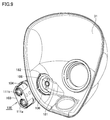
- FIG. 1 is a perspective view of a face piece 11 according to the embodiment.
- the face piece 11 is used by being worn on the head of a human body, and in the wearing state, the face piece main body 21 configured to cover the face of the wearer, and the face piece main body 21 fixed to the head of the wearer. It is comprised including the fastening string 22 for doing.
- the face body 21 includes a front plate 31 that is a colorless and transparent plate-like member having a size capable of covering the face of the human body, and the front plate 31 in the wearing state from the wearer's face in front of the wearer's face. And a support 32 that is supported at an appropriate interval.
- the front plate 31 is a member also called an eyepiece.
- one surface in the thickness direction of the front plate 31 and the surface facing the wearer's face in the wearing state is referred to as an inner surface
- the surface opposite to the inner surface is referred to as an outer surface.
- the front plate 31 is connected to an upper portion 36 that is disposed so as to face the upper half of the wearer's face, and a lower end portion of the upper portion 36, and is substantially on the lower half of the wearer's face. And a lower portion 37 arranged to face each other.
- the upper part 36 and the lower part 37 are formed to be bent and connected. Specifically, the lower portion 37 is formed to be bent toward the inner surface side with respect to the upper portion 36.
- Both the upper part 36 and the lower part 37 are formed in a smoothly curved shape so as to protrude in the direction away from the face of the wearer across the left and right end parts in the wearing state.
- a through hole is formed in the lower portion 37 so as to penetrate in the thickness direction in the center portion between the left and right end portions.
- a barrier holding portion to which one end of the barrier 33 is fixed is provided on the inner surface side thereof.
- the septum 33 is an annular seal member made of soft rubber having elasticity, and one end portion is fixed to the septum holding portion, and the other end portion is worn from the upper part of the wearer's nose to both cheeks and It is formed so as to cover the wearer's mouth and nose by elastic contact with the chin.
- an airtight breathing chamber is formed by the barrier 33 and the wearer's face, and inhalation gas is supplied to the breathing chamber.
- a rotating mechanism 100 is attached to the face piece 11.
- the rotation mechanism 100 is a member positioned between the air supply line 210 and the pressure detection line 220 and the front plate 31.
- One end of the rotation mechanism 100 is connected to the air supply line 210 and the pressure detection line 220.
- the other end of the rotation mechanism 100 is connected to the front plate 31.
- the face piece 11 covers the face of the wearer.
- the face plate 11 penetrates the front plate 31 which is a transparent plate member having a size capable of covering the face of the wearer, and the left and right of the wearer, and with respect to the front plate 31.
- a rotatable rotation mechanism 100 is attached to the face piece 11.
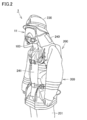
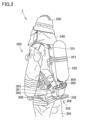
- FIGS. 2 and 3 are perspective views of the wearer 201 wearing the face piece 11 and the backpack 300 according to the embodiment.
- the wearer 201 wears protective clothing 200.
- the head of the wearer 201 is protected by the helmet 230, the face body 11, and the heart 240.
- the wearer 201 carries the backpack 300.
- a gas cylinder 250 is mounted on the backpack 300.
- the pressure demand valve is not provided on the body front surface 241 or the face body 11 of the protective clothing 200.
- the carrying device 300 extends from the upper part 331 to the lower part 332.
- a gas cylinder 250 having a shape extending from the upper part 331 toward the lower part 332 is fixed to the backpack 300 by a band 251.
- the tip of the gas cylinder 250 is inserted between the two rod-like portions 304 and 305 of the backpack 300.
- air which is a breathing gas containing oxygen, is compressed and filled in the gas cylinder 250 at a pressure higher than the atmospheric pressure as an intake gas.
- a bypass valve switch 301 and a positive pressure lock switch 302 are provided at the lower portion 332 of the backpack 300.
- the bypass valve switch 301 is a switch for guiding the high-pressure gas discharged from the gas cylinder 250 to the face body 11 without passing through the pressure demand valve 400 and the pressure reducing valve 460.
- the positive pressure lock switch 302 is for stopping the positive pressure supplied from the air supply line 210 to the face body 11. In a state where the wearer 201 has removed the face piece 11, the gas from the air supply line 210 continues to be supplied to the face piece 11, so that the supplied gas is not used at all and is released to the atmosphere. In order to prevent this, by operating the positive pressure lock switch 302 to cut off the supply of gas from the air supply line 210, it is possible to suppress wasteful consumption of gas.
- a guard bar 306 is provided at the lower portion 332 of the backpack 300.
- the guard bar 306 can protect the lower portion 332 of the backpack 300 and can make the backpack 300 stand on the ground.
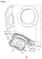
- FIG. 4 is a perspective view of rotating mechanism 100 according to the embodiment and front plate 31 to which rotating mechanism 100 is attached.
- the rotation mechanism 100 has a first main body 101.
- the first body 101 has a circular portion and a square portion.
- the upper body cover 103 and the lower body cover 104 are engaged with the rectangular portion of the first body 101.
- the main body lock 102 is engaged with the circular portion of the first main body 101.
- the body lock 102 is provided with notches 102a, 102b, and 102c.
- the main body lock 102 can rotate with respect to the front plate 31 together with the first main body 101.
- a pedestal 105 is provided in contact with the front plate 31.
- a leaf spring 118 is engaged with the pedestal 105.
- the engagement portion 118b provided at the tip of the leaf spring 118 is in contact with the main body lock 102.
- the pedestal 105 has an opening 105a.
- a connector 109 is provided between the base 105 and the main body lock 102.
- the pedestal 105 and the connector 109 do not rotate with respect to the front plate 31.
- the leaf spring 118 is fitted into one of the notches 102a, 102b, and 102c. Thereby, the rotation of the main body lock 102 can be stopped.
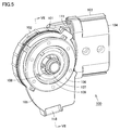
- FIG. 5 is a perspective view of rotation mechanism 100 according to the embodiment.
- the cylindrical member 108 is fitted to the first main body 101.
- a pedestal 105 is attached to the connector 109.
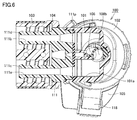
- FIG. 6 is a sectional view taken along the line VI-VI in FIG. As shown in FIG. 6, the second main body 111 is fitted to the first main body 101.
- the first main body 101 is provided with an internal space 101a.
- the second main body 111 is provided with protrusions 111c and 111d extending in parallel with each other.
- the protrusions 111c and 111d have a cylindrical shape, and the internal spaces 111a and 111b are provided to extend in the longitudinal direction.
- the internal spaces 111 a and 111 b communicate with the internal space 101 a of the first main body 101.
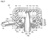
- FIG. 7 is a sectional view taken along line VII-VII in FIG. As shown in FIG. 7, the first main body 101 is sandwiched between the upper main body cover 103 and the lower main body cover 104. Circular internal spaces 111 a and 111 b are opened in the internal space 101 a of the first main body 101.
- a cylindrical member 108 is held in the first main body 101.
- the overhanging portion 108 c of the tubular member 108 is fitted to the tubular portion 101 c of the first main body 101.
- the cylindrical member 108 has a hollow shape and is positioned near the rotation axis of the first main body 101.
- the main body screw 107 is screwed to the outer periphery of the cylindrical portion 101c.
- the cylindrical member 108 is positioned in the first main body 101 by sandwiching a part of the protruding portion 108c between the main body screw 107 and the cylindrical portion 101c.
- the main body lock 102 is provided on the outer peripheral side of the cylindrical portion 101c.
- a collar 121 and a connector 109 are disposed between the cylindrical portion 101 c and the main body lock 102.
- a pedestal 105 is positioned below the flange portion 109f.
- a connector screw 106 is screwed into the end of the connector 109.
- a front plate 31 is sandwiched between the connector screw 106 and the base 105.
- the leaf spring 118 has an annular portion 118a sandwiched between the connector 109 and the pedestal 105, and an engaging portion 118b that is connected to the annular portion 118a and engages with the main body lock 102.
- the leaf spring 118 is made of an elastic material.
- the airtightness between the face body 11 and the rotation mechanism 100 is established by the following structure.
- Inner hoses 210a and 220a that constitute part of the metal serpentine for pressure detection and supply are connected to the protrusions 111c and 111d of the second main body 111 shown in FIG.
- the inner hoses 210a and 220a are made of rubber, and the airtightness between the protruding portions 111c and 111d and the inner hoses 210a and 220a is maintained by the contraction of the rubber.
- the second main body 111 is screwed to the first main body 101 via the packing 111p.
- the first main body 101 and the second main body 111 are kept airtight by crushing the packing 111p.
- the Y packing 131 is in contact with the first main body 101 and the collar 121.
- the Y packing 131 has little friction with respect to the outer diameter direction of the packing, and can rotate while maintaining the airtightness of the first main body 101 and the collar 121.
- the cylindrical member 108 is prevented from dropping from the first main body 101 by attaching the main body screw 107 to the first main body 101 by screw connection.
- a packing 132 is provided between the collar 121 and the connector 109. Further, by rotating the main body lock 102, the collar 121 is pressed against the connector 109 via the packing 132 and airtightness is maintained.
- FIG. 8 is an exploded perspective view of the rotation mechanism 100 according to the embodiment.
- the connector 109 is provided with a claw portion 109t extending in the circumferential direction.
- the main body lock 102 is provided with a groove 102n extending in the circumferential direction.
- the claw 109t fits in the groove 102n.
- the groove 102n is provided with a stopper (not shown), the end of the claw 109t in the circumferential direction hits the stopper, and the body lock 102 can be rotated by a predetermined angle with respect to the claw 109t. is there.
- the rotation mechanism 100 is fixed to the face plate 11 and has a pedestal 105 as a first member having an opening 105a.
- the rotation mechanism 100 is fitted to the opening 105a and can be rotated with respect to the pedestal 105. And a cylindrical member 108 as a second member having a passage therethrough.
- the rotation mechanism 100 includes a main body lock 102 as a rotatable third member and a leaf spring as a stop member that is fixed to the pedestal 105 and can stop the rotation of the main body lock 102 by engaging with the main body lock 102. 118.
- FIG. 9 is a perspective view of rotating mechanism 100 according to the embodiment and front plate 31 to which rotating mechanism 100 is attached.
- a connector screw 106 is provided inside the front plate 31.
- the claw portion 182 of the deflector 181 is engaged with the connector screw 106. Thereby, the deflector 181 is positioned in the front plate 31.
- FIG. 10 is a perspective view of the backpack 300 according to the embodiment.
- the backpack 300 has a main body 330.
- the main body 330 has a front plate 330a and a back plate 330b.
- the main body 330 extends from the upper part 331 to the lower part 332 in the longitudinal direction.
- a pair of belt holes 339 are provided in the upper portion 331.
- the upper part 331 refers to the upper half of the longitudinal direction
- the lower part 332 refers to the lower half of the longitudinal direction. That is, the main body 330 has an upper portion 331 located on the neck side of the wearer and a lower portion 332 located on the waist side of the wearer.
- the main body 330 is provided with four stoppers 307 for positioning the cylinder.
- a lid 335 is provided between the stoppers 307, and when the lid 335 is removed, a recess for allowing the air supply line and the pressure detection line to pass through is exposed.
- the body 330 is provided with a first joint 311.
- the first joint 311 is provided so as to be rotatable with respect to the main body 330 about the rotation shaft 311 a as a rotation center.
- a hose 312 is connected to the first joint 311.
- the hose 312 is provided so as to be rotatable with respect to the first joint 311 around the rotation shaft 312a.
- a second joint 313 is connected to the hose 312.
- the second joint 313 is provided so as to be rotatable with respect to the hose 312 around the rotation shaft 313a.
- a connector 314 provided at the tip of the second joint 313 can be screwed into the screwing portion 322 of the valve 320.
- the pair of rod-like portions 304 and 305 extend in a direction away from the front plate 330a.
- the pair of rod-like portions 304 and 305 are connected to the guard bar 306 in the main body 330.
- the rod-shaped parts 304 and 305 and the guard bar 306 are manufactured by bending a single bar.
- the main body 330 is provided with a protruding portion 303.
- a belt hole 309 is formed in the overhang portion 303.
- the overhang portion 303 is provided on the upper side 331 side of the bypass valve switch 301 and the positive pressure lock switch 302.
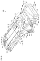
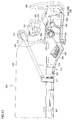
- FIG. 11 is a view showing a state in which the gas cylinder 250 is mounted on the backpack 300. As shown in FIG. 11, the position of the connector 314 in the longitudinal direction can be determined by rotating the first joint 311.
- FIG. 12 is a view showing a state in which the gas cylinder 250 is mounted on the backpack 300. By rotating the hose 312 as shown in FIG. 12, the position of the connector 314 in the height direction can be determined.
- FIG. 13 is a view showing a state in which the gas cylinder 250 is mounted on the backpack 300. As shown in FIG. 13, the angle of the connector 314 can be determined by rotating the second joint 313.
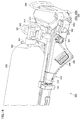
- FIG. 14 is a view showing a state in which the gas cylinder 250 is mounted on the backpack 300. As shown in FIG. 14, the valve 320 and the connector 314 can be connected by screwing the connector 314 to the valve 320.
- FIG. 15 is a diagram showing an air supply line 210 and a pressure detection line 220.
- FIG. 16 is a cross-sectional view of the air supply line 210 and the pressure detection line 220.
- the air supply line 210 and the pressure detection line 220 include inner hoses 210a and 220a made of rubber, and outer cases 210b and 220b that cover the inner hoses 210a and 220a.
- the outer cases 210b and 220b are flexible casing tubes, which are made of metal and can be bent.
- connectors 211 and 212 are provided at both ends of the air supply line 210 and the pressure detection line 220.
- FIG. 17 is a perspective view of the backpack 300. As shown in FIG. 17, the back plate 330 b extends from the upper part 331 to the lower part 332 of the backpack 300. A drain plug cover 380 is provided on the lower portion 332 of the back plate 330b. A cover 302 a covers the positive pressure lock switch 302.
- FIG. 18 is a perspective view of the backpack 300 with the drain plug cover 380 removed.
- the drain plug cover 380 is removed from the back plate 330b as shown in FIG. 18, the drain plug 430 is visible.
- FIG. 19 is a perspective view showing the internal structure of the backpack 300 with the back plate 330b removed.
- the adjuster 450 is accommodated in the front plate 330a.
- the regulator 450 includes a pressure reducing valve 460 and a pressure demand valve 400, and a drain plug 430 is provided in the pressure demand valve 400.
- the water 433 accumulated in the pressure demand valve 400 can be discharged from the drain plug 430.
- the pressure reducing valve 460 and the pressure demand valve 400 are provided in the lower part 332 of the main body.
- FIG. 20 is a perspective view showing the internal structure of the backpack 300 with the drain plug 430 removed from the case 401. As shown in FIG. 20, an opening 431 is provided in the case 401. A drain plug 430 is provided in the circular opening 431 so as to be fitted therein.
- FIG. 21 is a perspective view showing the internal structure of the backpack 300 with the adjuster 450 removed from the back plate 330b.
- the back plate 330b is provided with a groove 330c extending from the upper part 331 toward the lower part 332.
- An air supply line 210 and a pressure detection line 220 are disposed in the groove 330c.
- the case 401 has a dead end, so that water easily collects in this portion.
- the drain plug 430 the water 433 can be easily discharged.
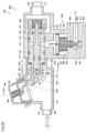
- FIG. 22 is a cross-sectional view showing the internal structure of the pressure demand valve 400.
- the pressure demand valve 400 has a regulator body 413.
- the adjuster main body 413 has an inlet 418 and an air supply port 423 which is an outlet.
- the pressure demand valve main body 415 is fitted to the adjuster main body 413.
- the pressure demand valve body 415 cannot move relative to the regulator body 413.
- a shaft 417 is slidably fitted to the cylindrical portion of the pressure demand valve main body 415.
- the case 401 is in contact with the adjuster body 413.
- the case 401 is provided with a diaphragm 403.
- a positive pressure spring 406 is provided on one side of the diaphragm 403, and a lever 405 is provided on the other side.
- the case 401 is provided with a pressure detection port 402.
- a pressure detection line 220 is inserted into the pressure detection port 402.
- a positive pressure lock shaft 410 is disposed in the case 401.
- the positive pressure lock shaft 410 is connected to the second auxiliary lever 409.
- the first auxiliary lever 408 is attached to the cap 426.
- the positive pressure lock shaft 410 is connected to the positive pressure lock switch 302.
- the pressure demand valve 400 has a function of supplying air having a pressure slightly higher than the atmospheric pressure to the face body 11 according to breathing.
- the pressure demand valve 400 realizes the function by the following structure.
- Medium pressure (1 MPa or less) air flows from the inlet 418 of the regulator body 413 to the pressure demand valve body 415.
- the medium pressure air is sealed between the pressure demand valve main body 415 and the regulator main body 413 by the first O-ring 412 and the second O-ring 414.
- a shaft 417 passes through the pressure demand valve main body 415, and a valve body 419 is connected to the shaft 417 by a nut 420.
- the valve body 419 is a composite material of metal and rubber. The rubber portion of the valve body 419 is pressed against the seat surface of the pressure demand valve main body 415 by the valve spring 422 fixed by the spring receiver 421, thereby stopping the flow of medium pressure air. Further, a U seal 416 is attached to the shaft 417 so that medium pressure air does not flow to the case 401 side.
- the case 401 and the pressure demand valve main body 415 are coupled, and an O-ring 411 is provided at the coupling portion to prevent the pressure in the case 401 from flowing into the atmosphere.
- the case 401 is connected to the face piece 11 by the pressure detection port 402, and the pressure fluctuation in the face piece 11 according to breathing is transmitted into the case 401.
- the diaphragm 403 is made of rubber and is sandwiched between the cover 404 and the case 401, and the air in the case 401 does not leak to the cover 404 side.
- the pressure in the case 401 fluctuates due to the breathing of the wearer 201.
- the pressure of the case 401 varies, the shape of the diaphragm 403 is deformed due to the variation in pressure.
- the lever 405 is connected to the diaphragm 403, and when the diaphragm 403 is deformed, the lever 405 rotates around the rotation shaft 407.
- the rotating shaft 407 is fixed by a cap 426, and the cap 426 is coupled to the pressure demand valve main body 415.
- the adjuster main body 413 constitutes a case (main body) of the pressure reducing valve 460.
- the pressure demand valve 400 and the pressure reducing valve 460 are integrally formed with the regulator 450.
- the backpack 300 includes the regulator 450 in which the pressure reducing valve 460 and the pressure demand valve 400 attached to the main body 330 are integrated.
- the high pressure air at the pressure P1 is reduced to the medium pressure air at the pressure P2.
- a high pressure valve seat 461 is embedded in the adjuster body 413.
- the shaft 462 of the piston 463 is in contact with the high pressure valve seat 461.
- the piston 463 is housed in the decompression chamber 470.
- a spring 465 pushes the piston 463.
- An O-ring 466 is provided between the shaft 462 and the adjuster body 413.
- An O-ring 467 is provided between the umbrella portion of the piston 463 and the adjuster body 413. Airtightness is maintained by these O-rings 466 and 467.
- FIG. 23 is a cross-sectional view showing a state in which the medium-pressure air flows into the air supply port 423 in the pressure demand valve 400 according to the respiration rate.
- the lever 405 rotates.
- the end 405 c of the lever 405 pushes the end 417 of the shaft 417.
- the valve body 419 moves in conjunction with the shaft 417, a gap is created between the pressure demand valve body 415 and the valve body 419, and medium pressure air flows to the air supply port 423 according to the respiration rate.
- the air supply port 423 is connected to the face body 11 through the air supply line 210.
- the pressure in the face body 11 fluctuates due to the air supplied to the face body 11, and the fluctuating pressure is detected by the pressure sensing port 402 via the pressure sensing line 220, and the diaphragm 403 moves by this pressure fluctuation.
- the positive pressure spring 406 fixed by the cover 404 applies a load corresponding to the compression amount to the diaphragm 403.
- the cover 404 has a hole for transmitting the atmosphere, and the vicinity of the positive pressure spring 406 is atmospheric pressure. Due to the load applied by the positive pressure spring 406, the pressure inside the case 401 is higher than the atmospheric pressure.
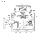
- FIG. 24 is a sectional view taken along the line XXIV-XXIV in FIG.
- the positive pressure lock shaft 410 is rotated.
- the second auxiliary lever 409 rotates in conjunction with the positive pressure lock shaft 410 and the shaft 410s.
- the second auxiliary lever 409 pushes up the first auxiliary lever 408, the first auxiliary lever 408 rides on the protrusion 426a provided on the cap 426, and the position of the first auxiliary lever 408 is fixed.
- the lever 405 cannot move the first auxiliary lever 408 over the protrusion 426a of the cap 426 and return to the original position with the force of only the positive pressure spring 406 transmitted through the diaphragm 403. Is fixed. Since the lever 405 is fixed, the valve body 419 is not opened and air does not flow into the face body 11 through the air supply port 423.
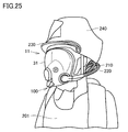
- FIG. 25 is a diagram of the wearer 201 in a state where the roller 240 is lifted. 2 and 3, the rotating mechanism 100 does not appear because the roller 240 has been lowered. However, since the roller 240 is lifted in FIG. 23, the rotating mechanism 100, the air supply line 210, and the pressure detection line 220 are exposed. To do.
- the air supply line 210 and the pressure detection line 220 are preferably arranged on the left side of the wearer 201. This is because the wearer 201 carries a fire hose on the right shoulder, and if the air supply line 210 and the pressure detection line 220 are provided on the right side, the wearer 201 interferes with the fire hose.
- the structure for rotating and locking the rotating mechanism 100 with respect to the face piece 11 is as follows. First, the annular portion 118 a of the leaf spring 118 is attached to the pedestal 105.
- the engaging portion 118b is pushed down to the pedestal 105 side. As a result, the engagement between the engagement portion 118b and any one of the notches 102a, 102b, and 102c is released. As a result, the main body lock 102 can be rotated.
- the respiratory apparatus 1 has the following characteristics.
- An adjuster 450 that is a component of the respirator 1 is disposed on the backpack 300. Thereby, compared with the case where the adjuster 450 is arrange
- the exposed portion of the arranged adjuster 450 is covered with a front plate 330a as a separate part. Further, a guard bar 306 is provided which is a metal fitting that can stand on its own without directly contacting the adjuster 450.
- the regulator 450 includes a decompression unit (decompression valve 460) that decompresses high-pressure air, and a supply unit (pulmonary force valve (pressure demand valve 400)) that supplies an appropriate amount of decompressed air to the wearer according to the respiration rate.
- a decompression unit decompression valve 460
- a supply unit pulmonary force valve (pressure demand valve 400)
- An air supply line 210 and a pressure detection line 220 which are breathing hoses (breathing hoses) connecting the face body 11 and the regulator 450, are connected to the face body 11 without passing through the front face 241 from the rear of the wearer. Is done.
- a part of the air supply line 210 and the pressure detection line 220 is housed in the backpack 300.
- the distance by which the neck is moved is expanded and contracted.
- the fitting (rotation mechanism 100) of the face piece 11, the air supply line 210, and the pressure detection line 220 is rotated with respect to the face piece 11 while maintaining the state of protection from the outside air in the face piece 11 when the respirator 1 is worn. It is a structure that can.
- the hose connecting the respirator 1 and the high-pressure air container (gas cylinder 250) varies in size due to the eccentricity during rotation by providing a multi-axis rotating shaft on the metal fitting for connecting the hose (hereinafter, high-pressure hose connecting metal fitting).
- the respirator 1 When using the respirator 1 for activities in a narrow area, there are situations where it is necessary to perform actions such as becoming hungry, squatting, or holding a ladder. If the regulator 450, the air supply line 210, and the pressure detection line 220 are present on the front surface 241, the activity is hindered due to interference by components.
- the respirator 1 does not have the adjuster 450, the air supply line 210, and the pressure detection line 220 on the front surface of the body, so that the body can be more closely attached to the ground or a ladder, and the activity is improved.
- the respirator 1 is provided with a part that covers the exposed portion of the adjuster 450 and a guard bar 306 that is a self-supporting metal fitting that does not come into direct contact with the adjuster 450, and protects the adjuster 450 from impact against collision and dropping. It has the structure to do.
- Integrating the regulator 450 eliminates the hose connecting the pressure reducing valve 460 and the pressure demand valve 400 (hereinafter, medium pressure hose). Since the medium pressure hose is made of rubber, it deteriorates over time, but maintenance is improved by the absence of the hose. Moreover, the regulator 450 is reduced in size by eliminating the intermediate pressure hose.
- the wearer 201 moves his / her neck when confirming left / right, top / bottom, and various postures.
- the neck moves beyond the elasticity of the hose, the hose is pulled against the swing of the neck.
- the hose may be caught during the activity.
- the supply line 210 and the pressure detection line 220 expand and contract in accordance with the movement of the neck to relieve stress on the neck, and the supply line 210 and the pressure detection line 220 are By storing it in the backpack 300, exposure of an extra hose is suppressed and activity is improved.
- Rotation mechanism 100 rotates to relieve stress on the neck by following up / down / left / right movements of the neck when worn.
- the respirator 1 is worn, when the face body 11 is taken off (standby state), when water enters the air supply line 210, the pressure detection line 220, and the adjuster 450 through the face body due to support drainage or the like, Corrosion and freezing at low temperatures may cause the respiratory apparatus 1 to fail.
- the face body 11 By rotating the rotation mechanism 100, the face body 11 can be rotated in a standby state in a direction in which the water for supporting and discharging water does not enter.
- the gas cylinder 250 has a different internal volume depending on the amount of air carried, and the size of the container itself is different.
- the hose connected to the gas cylinder 250 generally has a multilayer structure to withstand high-pressure air, and the hose itself is inferior in elasticity. For this reason, when connecting a hose to the gas cylinders 250 of different sizes, it is necessary to provide a high degree of freedom for the high-pressure hose connection fitting or to adjust the position where the gas cylinder 250 is fixed to the backpack.
- a high degree of freedom is provided in the high-pressure hose connection fitting, when the position is adjusted by sliding the high-pressure hose connection fitting, frictional force is applied depending on the mass of the component and the configuration of the component connected to the high-pressure hose connection fitting. Since the connection to the gas cylinder 250 is always performed when the respirator 1 is used, repeated operations lead to stress on the wearer 201 and wear of the equipment.
- a high-pressure hose connection fitting 310 is provided as a guide path for guiding the gas in the gas cylinder 250 from the outside of the main body 330 into the main body 330.
- the high-pressure hose connection fitting 310 has a first joint 311, a hose 312, and a second joint 313.
- the high-pressure hose connection fitting 310 can rotate along a plurality of axes.
- the connectivity to the gas cylinder 250 is improved by providing and connecting a multi-axis rotating shaft to the high-pressure hose connection fitting 310.
- the high-pressure hose connection fitting 310 has three rotation shafts 311a, 312a, and 313a, but may have more or fewer rotation shafts.
Landscapes
- Health & Medical Sciences (AREA)
- Pulmonology (AREA)
- General Health & Medical Sciences (AREA)
- Business, Economics & Management (AREA)
- Emergency Management (AREA)
- Emergency Medicine (AREA)
- Life Sciences & Earth Sciences (AREA)
- Zoology (AREA)
- Engineering & Computer Science (AREA)
- Mechanical Engineering (AREA)
- Ocean & Marine Engineering (AREA)
- Respiratory Apparatuses And Protective Means (AREA)
Abstract
着装者の動作を妨げない背負い具を提供する。 ガスボンベが取り付けられる、着装者が背負う背負い具(300)であって、ガスボンベが取り付けられる本体と、本体に取り付けられる減圧弁(460)およびプレッシャデマンド弁(450)とが一体となった調整器と、を備える。
Description
本開示は、背負い具に関するものである。
消防隊員は、火事が起こっている現場など危険な場所での救助活動を行う。そのため、消防隊員は、救助活動を行う際に呼吸器を着装しておく。
このような呼吸器に関し、米国特許明細書5000174号(特許文献1)では、陽圧呼吸装置が開示されている。
従来の呼吸器では、着装者である消防隊員は、動作が困難になることがあった。
ある局面に従うと、ボンベが取り付けられる、着装者が背負う背負い具であって、本体と、本体に取り付けられる減圧弁およびプレッシャデマンド弁とが一体となった調整器を備える。
このように構成された背負い具においては、本体に弁圧弁およびプレッシャデマンド弁が設けられるため、着装者の背負い具の胸部に配したベルトや面体にこれらの弁が取り付けられることがない。その結果、着装者の動作を妨げない。さらに減圧弁およびプレッシャデマンド弁が一体となって構成されているため、これらが互いに分離することが無く、故障の発生を抑制できる。さらに、調整器をコンパクトにすることができる。減圧弁とプレッシャデマンド弁を分離した場合中圧用ホースで減圧弁とプレッシャデマンド弁とを接続する必要がある。その場合には、接続コネクタと、接続用コネクタとホースをかしめる金具とホースとをそれぞれ積み上げた長さが必要となるため、スペースが大きくなり質量が増えて活動性が損なわれる。
好ましくは、本体は、着装者の首側に位置する上部と着装者の腰側に位置する下部とを有し、減圧弁およびプレッシャデマンド弁は、本体の下部に設けられる。この場合、重量物である減圧弁およびプレッシャデマンド弁が下部に集められるため、着装者の動作を妨げない。
好ましくは、本体には上部から下部に延びる溝が設けられており、面体内の圧力を検知する検圧ラインと、面体内にガスを送る給気ラインとが溝に配置される。この場合、溝内に検圧ラインと給気ラインとが設けられるため、検圧ラインおよび吸気ラインが着装者や外的物品に接触することを防止できる。その結果、着装者の動作を妨げない。
好ましくは、ガスボンベから減圧弁の間には本体外から本体内へボンベのガスを導く誘導路が設けられており、誘導路は、複数の軸に沿って回転することが可能である。この場合、誘導路は複数の軸に沿って回転することが可能であるため、ガスボンベの大きさにかかわらず、ガスボンベと誘導路とを接続することが可能である。
呼吸器は、上記のいずれかの背負い具と、背負い具からガスが供給されて着装者の顔面を覆う面体とを備える。
以下、図面を参照しつつ、本発明に従う各実施の形態について説明する。以下の説明では、同一の部品および構成要素には同一の符号を付してある。それらの名称および機能も同じである。したがって、これらについての詳細な説明は繰り返さない。
図1は、実施の形態に従う面体11の斜視図である。
面体11は、人体の頭部に着装されて使用されるものであり、着装状態において、着装者の顔面を覆うように構成される面体本体21と、面体本体21を着装者の頭部に固定するための締め紐22とを含んで構成される。
面体11は、人体の頭部に着装されて使用されるものであり、着装状態において、着装者の顔面を覆うように構成される面体本体21と、面体本体21を着装者の頭部に固定するための締め紐22とを含んで構成される。
面体本体21は、人体の顔面を被覆可能なサイズを有する無色透明の板状部材である前面板31と、着装状態において、前面板31を、着装者の顔面の前方に、着装者の顔面から適度な間隔をあけて支持する支持体32とを含んで構成される。この前面板31は、アイピースとも称される部材である。
以下、前面板31における厚み方向の一方の表面であって、着装状態において着装者の顔面に臨む側の表面を内表面と称することとし、内表面とは反対側の表面を外表面と称することとする。
前面板31は、着装状態において、着装者の顔面の大略的に上半分に対向するように配置される上部36と、上部36の下端部に連なり、着装者の顔面の大略的に下半分に対向するように配置される下部37とを有する。上部36と下部37とが屈曲して連なるように形成されている。詳細には、上部36に対して、下部37が内表面側に屈曲するように形成されている。
上部36および下部37はいずれも、着装状態において、その左右の両端部間にわたって、着装者の顔面から離反する方向に凸となるように滑らかに湾曲した形状に形成されている。また、下部37には、その左右の両端部間の中央部に、厚み方向に貫通するように透孔が形成されている。
この下部37の中央部にはその内表面側に、隔障33の一端部が固定される隔障保持部が設けられる。
隔障33は、弾力性を有する軟質ゴムから成る環状のシール部材であり、一端部は隔障保持部に固定され、他端部は、着装状態において、着装者の鼻の上部から両頬および顎にかけて弾発的に面接触することで、着装者の口および鼻を覆うように形成されている。このように着装状態では、隔障33と着装者の顔面とによって気密性を有する呼吸室が形成され、この呼吸室には、吸気ガスが供給される。
面体11には、回転機構100が取り付けられる。回転機構100は、給気ライン210および検圧ライン220と前面板31との中間に位置する部材である。給気ライン210および検圧ライン220に回転機構100の一方端が接続される。前面板31に回転機構100の他方が接続される。面体11は着装者の顔面を覆う。面体11は着装者の顔面を被覆可能なサイズを有する透明の板状部材である前面板31と、着装者の左右のいずれかにおいて前面板31を貫通して、かつ、前面板31に対して回転可能な回転機構100とを備える。
図2および図3は、実施の形態に従う面体11および背負い具300を着装した着装者201の斜視図である。着装者201は防護服200を着用している。着装者201の頭部は、ヘルメット230、面体11および、シコロ240により保護されている。着装者201は背負い具300を背負っている。背負い具300にはガスボンベ250が着装されている。防護服200の体前面241あるいは面体11にプレッシャデマンド弁が設けられていない。
背負い具300は上部331から下部332へ延びている。上部331から下部332に向かって延びる形状のガスボンベ250はバンド251により背負い具300に固定されている。背負い具300の2つの棒状部304,305の間にガスボンベ250の先端が挿入されている。酸素を含む呼吸用気体であるたとえば空気が、吸気ガスとして大気圧よりも高い圧力でガスボンベ250に圧縮充填される。
背負い具300の下部332にはバイパス弁スイッチ301および陽圧ロックスイッチ302が設けられている。バイパス弁スイッチ301はガスボンベ250から排出された高圧のガスを、プレッシャデマンド弁400および減圧弁460を経由せずに面体11へ導くためのスイッチである。
陽圧ロックスイッチ302は、給気ライン210から面体11へ供給される陽圧を停止するためのものである。着装者201が面体11を取り外した状態では、給気ライン210からのガスが面体11は供給され続けるため、供給されたガスは何ら利用されず大気に放出されることになる。これを防止するために、陽圧ロックスイッチ302を操作して給気ライン210からのガスの供給を遮断することで、ガスが無駄に消費されることを抑制できる。
背負い具300の下部332にはガードバー306が設けられる。ガードバー306は背負い具300の下部332を保護すると共に、背負い具300を地面上で自立させることができる。
図4は、実施の形態に従う回転機構100および回転機構100が取り付けられる前面板31の斜視図である。図4で示すように、回転機構100は第一本体101を有する。第一本体101は円形部分と角形部分とを有する。第一本体101の角形部分には上側本体カバー103および下側本体カバー104が係合する。
第一本体101の円形部分には本体ロック102が係合する。本体ロック102には切欠102a,102b,102cが設けられている。本体ロック102は第一本体101とともに前面板31に対して回転することが可能である。
前面板31と接触するように台座105が設けられている。台座105には板ばね118が係合している。板ばね118の先端に設けられた係合部118b本体ロック102に当接している。台座105は開口105aを有する。
台座105と本体ロック102との間にコネクタ109が設けられている。台座105およびコネクタ109は前面板31に対して回転しない。本体ロック102を回転させると、板ばね118は切欠102a,102b,102cのいずれかに嵌り合う。これにより本体ロック102の回転を停止させることができる。
図5は、実施の形態に従う回転機構100の斜視図である。図5で示すように、第一本体101に筒状部材108が嵌合している。筒状部材108の周りには、本体ネジ107、コネクタ109およびコネクタネジ106が存在する。コネクタ109に台座105が取り付けられている。
図6は、図4中のVI-VI線に沿った断面図である。図6で示すように、第一本体101に第二本体111が嵌合している。第一本体101には内部空間101aが設けられている。
第二本体111には互いに平行に延びる突出部111c,111dが設けられている。突出部111c,111dはそれぞれ円筒形状であり、その内部空間111a,111bは長手方向に延びるように設けられている。内部空間111a,111bは、第一本体101の内部空間101aに連通している。
図7は、図5中のVII-VII線に沿った断面図である。図7で示すように、第一本体101は、上側本体カバー103および下側本体カバー104で挟まれている。第一本体101の内部空間101aに円形状の内部空間111a,111bが開口している。
第一本体101内に筒状部材108が保持されている。筒状部材108の張出部108cが第一本体101の筒状部101cに嵌合している。筒状部材108は中空形状であり、第一本体101の回転軸付近に位置する。
本体ネジ107が筒状部101cの外周に螺合している。本体ネジ107と筒状部101cとの間に張出部108cの一部分が挟まれることで筒状部材108が第一本体101内で位置決めされる。
本体ロック102は筒状部101cの外周側に設けられる。筒状部101cと本体ロック102との間にはカラー121およびコネクタ109が配置されている。フランジ部109fの下側には台座105が位置している。コネクタ109の端部にコネクタネジ106が螺合している。コネクタネジ106と台座105との間に前面板31が挟まれている。
板ばね118は、コネクタ109および台座105で挟まれる環状部118aと、環状部118aに接続されて本体ロック102に係合する係合部118bとを有する。板ばね118は弾性材料により構成される。
面体11と回転機構100との気密は次の構造により成り立つ。
図6で示す第二本体111の突出部111c、111dに、検圧用、給気用の金属蛇管の一部分を構成するインナーホース210a,220aを接続する。インナーホース210a,220aはゴムで出来ており、ゴムの収縮で突出部111c、111dとインナーホース210a,220a間の気密は保たれる。
図6で示す第二本体111の突出部111c、111dに、検圧用、給気用の金属蛇管の一部分を構成するインナーホース210a,220aを接続する。インナーホース210a,220aはゴムで出来ており、ゴムの収縮で突出部111c、111dとインナーホース210a,220a間の気密は保たれる。
第二本体111は、第一本体101とパッキン111pを介してねじ結合される。第一本体101と第二本体111はパッキン111pのつぶしにより気密が保たれる。
図7で示すように、第一本体101とカラー121とにYパッキン131が接している。Yパッキン131はパッキンの外径方向に対して摩擦が少なく、第一本体101とカラー121の気密を保持しながら、回転することができる。また、本体ネジ107を第一本体101にねじ結合により取り付けることによって、筒状部材108が第一本体101から脱落するのを防ぐ。
カラー121とコネクタ109との間にはパッキン132が設けられている。また本体ロック102を回転させることにより、カラー121はパッキン132を介してコネクタ109に押し付けられ気密は保たれる。
図8は、実施の形態に従う回転機構100の分解斜視図である。図8で示すように、コネクタ109には円周方向に延びる爪部109tが設けられている。本体ロック102には円周方向に延びる溝102nが設けられている。溝102n内に爪部109tが嵌り合う。溝102nにはストッパ(図示せず)が設けられており、爪部109tの円周方向の端部がストッパに当たり、本体ロック102は爪部109tに対して所定の角度だけ回転することが可能である。回転機構100は、面体11に固定されて開口105aを有する第一部材としての台座105と、開口105aに嵌合して台座105に対して回転可能であり、前面板31を貫通してガスを通す経路を有する第二部材としての筒状部材108とを有する。回転機構100は、回転可能な第三部材としての本体ロック102と、台座105に固定され、本体ロック102に係合することで本体ロック102の回転を停止することができる停止部材としての板ばね118とをさらに備える。
図9は、実施の形態に従う回転機構100および回転機構100が取り付けられる前面板31の斜視図である。図9で示すように、前面板31の内側にコネクタネジ106が設けられる。コネクタネジ106にはデフレクタ181の爪部182が係合している。これにより、デフレクタ181が前面板31内で位置決めされる。
図10は、実施の形態に従う背負い具300の斜視図である。図10で示すように、背負い具300は、本体330を有する。本体330は、表板330aおよび背板330bを有する。
本体330は上部331から下部332へ長手方向に延びる。上部331には一対のベルト孔339が設けられている。上部331は長手方向の上半分をいい、下部332は長手方向の下半分をいう。すなわち、本体330は、着装者の首側に位置する上部331と着装者の腰側に位置する下部332とを有する。
本体330には、ボンベを位置決めするための4つのストッパ307が設けられている。ストッパ307の間には蓋体335が設けられており、蓋体335を外すと給気ラインおよび検圧ラインを通すための凹部が露出する。
本体330には、第一継手311が設けられる。第一継手311は本体330に対して回転軸311aを回転中心として回転可能に設けられる。ホース312が第一継手311に接続される。ホース312は第一継手311に対して回転軸312aを回転中心として回転可能に設けられる。第二継手313がホース312に接続される。第二継手313はホース312に対して回転軸313aを回転中心として回転可能に設けられる。第二継手313の先端に設けられたコネクタ314は、バルブ320の螺合部322に対して螺合可能である。
一対の棒状部304,305は、表板330aから離れる方向に延びている。一対の棒状部304,305は本体330内でガードバー306と接続されている。一本の棒を曲げることで棒状部304,305およびガードバー306が製造される。
本体330には張出部303が設けられている。張出部303にはベルト孔309が形成されている。張出部303は、バイパス弁スイッチ301および陽圧ロックスイッチ302よりも上部331側に設けられている。
図11は、背負い具300にガスボンベ250を着装した状態を示す図である。図11で示すように第一継手311を回転させることで、コネクタ314の長手方向の位置を決定することができる。
図12は、背負い具300にガスボンベ250を着装した状態を示す図である。図12で示すようにホース312を回転させることで、コネクタ314の高さ方向の位置を決定することができる。
図13は、背負い具300にガスボンベ250を着装した状態を示す図である。図13で示すように、第二継手313を回転させることで、コネクタ314の角度を決定することができる。
図14は、背負い具300にガスボンベ250を着装した状態を示す図である。図14で示すように、コネクタ314をバルブ320に螺合させることで、バルブ320とコネクタ314とを接続することができる。
図15は、給気ライン210および検圧ライン220を示す図である。図16は、給気ライン210および検圧ライン220の断面図である。図15および図16で示すように、給気ライン210および検圧ライン220は、ゴムにより構成されるインナーホース210a,220aと、インナーホース210a,220aを覆うアウターケース210b,220bとを有する。アウターケース210b,220bはフレキシブルケーシングチューブであり、金属製でありかつ曲げることができる。図15で示すように給気ライン210および検圧ライン220の両端にはコネクタ211,212が設けられている。
図17は、背負い具300の斜視図である。図17で示すように、背板330bは背負い具300の上部331から下部332まで延びる。背板330bの下部332にはドレンプラグカバー380が設けられている。カバー302aが陽圧ロックスイッチ302を覆う。
図18は、ドレンプラグカバー380を外した状態の背負い具300の斜視図である。図18で示すようにドレンプラグカバー380を背板330bから外すと、ドレンプラグ430が見える。
図19は、背板330bを外した状態の背負い具300の内部構造を示す斜視図である。図19で示すように、表板330aに調整器450が収納されている。調整器450は、減圧弁460と、プレッシャデマンド弁400とを有するプレッシャデマンド弁400にはドレンプラグ430が設けられている。プレッシャデマンド弁400内に溜まった水433をドレンプラグ430から排出することが可能である。減圧弁460およびプレッシャデマンド弁400は、本体の下部332に設けられる。
図20は、ドレンプラグ430をケース401から外した状態の背負い具300の内部構造を示す斜視図である。図20で示すように、ケース401に開口431が設けられている。円形の開口431にドレンプラグ430が嵌合可能に設けられている。
図21は、背板330bから調整器450を外した状態の背負い具300の内部構造を示す斜視図である。図21で示すように、背板330bには上部331から下部332へ向かって延びる溝330cが設けられている。溝330cには給気ライン210および検圧ライン220が配置される。検圧ライン220に水が浸入した場合には、ケース401で行き止まりとなるためこの部分に水がたまりやすい。ドレンプラグ430を設けることで、水433を容易に排出することが可能である。
図22は、プレッシャデマンド弁400の内部構造を示す断面図である。図22で示すように、プレッシャデマンド弁400は調整器本体413を有する。調整器本体413には、入口部418および出口である給気口423を有する。
調整器本体413にはプレッシャデマンド弁本体415が嵌合している。プレッシャデマンド弁本体415は調整器本体413に対して動くことができない。プレッシャデマンド弁本体415の筒状部分には軸417がスライド可能に嵌合している。
調整器本体413にはケース401が接触している。ケース401にはダイヤフラム403が設けられている。ダイヤフラム403の一方側には陽圧ばね406が設けられており、他方側にはレバー405が設けられている。
ケース401には検圧口402が設けられている。検圧口402には検圧ライン220が挿入されている。ケース401には陽圧ロック軸410が配置されている。陽圧ロック軸410は第二補助レバー409が接続されている。第一補助レバー408はキャップ426に取付けられている。陽圧ロック軸410は陽圧ロックスイッチ302に接続されている。
プレッシャデマンド弁400は呼吸に応じて、大気圧よりもわずかに高い圧力の空気を面体11に供給する機能を有する。プレッシャデマンド弁400は当該機能を次の構造により実現する。
調整器本体413の入口部418から中圧(1MPa以下)空気がプレッシャデマンド弁本体415に流れる。中圧空気は第一Oリング412と第二Oリング414でプレッシャデマンド弁本体415と調整器本体413間で密閉される。
プレッシャデマンド弁本体415の内部には、軸417が通っており、軸417には弁胴419がナット420により連結されている。弁胴419は金属とゴムの複合材である。ばね受け421で固定された弁ばね422で、プレッシャデマンド弁本体415のシート面に弁胴419のゴム部分が押えつけられることにより、中圧空気の流れを止める。また軸417にはUシール416が取り付けてあり、中圧空気がケース401側に流れないようにする。
ケース401とプレッシャデマンド弁本体415は結合されており、結合部にOリング411がありケース401内の圧力が大気に流れることを防いでいる。
ケース401は検圧口402により面体11とつながっており、呼吸に応じた面体11内の圧力変動がケース401内に伝達する。ダイヤフラム403はゴムで出来ており、カバー404とケース401で挟まれており、ケース401内の空気はカバー404側には漏れない。
ケース401は検圧ライン220により面体11と接続されているため、着装者201の呼吸によってケース401内の圧力が変動する。ケース401の圧力が変動すると、ダイヤフラム403が圧力の変動を受けて形状が変形する。
ダイヤフラム403には、レバー405がつながっており、ダイヤフラム403が変形するとレバー405は回転軸407を中心にして回転する。回転軸407はキャップ426によって固定されていて、キャップ426はプレッシャデマンド弁本体415と結合されている。
調整器本体413は、減圧弁460のケース(本体)を構成している。その結果、プレッシャデマンド弁400および減圧弁460は、調整器450に一体に形成されている。言い換えれば、背負い具300は、本体330に取り付けられる減圧弁460およびプレッシャデマンド弁400が一体となった調整器450を備える。
減圧弁460では、圧力P1の高圧の空気を減圧して圧力P2の中圧の空気とする。調整器本体413には高圧弁シート461が埋め込まれている。高圧弁シート461にピストン463の軸462が接触している。ピストン463は減圧室470に収納されている。ばね465がピストン463を押している。プレッシャデマンド弁400側の圧力P2が小さくなれば圧力P2がピストン463を押す力が小さくなり、ピストン463は図22で示す位置から軸417へ近づく方向に移動する。これにより軸462が高圧弁シート461から離れ、軸462に設けられた通路464内を空気が通過する。この空気により入口部418の圧力P2が高くなると圧力P2がピストン463を押す力が強くなり軸462が高圧弁シート461に押付けられる。
軸462と調整器本体413との間にはOリング466が設けられる。ピストン463の傘部分と調整器本体413との間にはOリング467が設けられる。これらのOリング466,467により気密が保たれる。
図23は、プレッシャデマンド弁400において、呼吸量に応じて中圧空気が給気口423に流れている状態を示す断面図である。図23で示すように、呼吸によりダイヤフラム403が変動すると、レバー405が回転する。レバー405の端部405cが軸417の端部417を押す。弁胴419が軸417と連動して動き、プレッシャデマンド弁本体415と弁胴419の間に隙間が出来て、呼吸量に応じて中圧空気が給気口423に流れる。
給気口423は、給気ライン210により面体11とつながっている。面体11に供給された空気によって面体11内の圧力が変動し、変動した圧力を検圧ライン220を介して検圧口402で検知し、この圧力変動によってダイヤフラム403が動く。
カバー404により固定された陽圧ばね406は、ダイヤフラム403に圧縮量に応じた荷重を与える。カバー404は大気を伝達する穴があいており、陽圧ばね406付近は大気圧となる。陽圧ばね406で与えた荷重によりケース401内は大気圧よりも高い圧力となる。
図24は、図22中の矢印XXIV-XXIV線に沿った断面図である。呼吸器を使用しない場合は、陽圧ロック軸410を回転させる。陽圧ロック軸410を矢印RSで示す方向に回転させると、陽圧ロック軸410およびシャフト410s連動して第二補助レバー409が回転する。第二補助レバー409の回転により、第二補助レバー409が第一補助レバー408を押し上げキャップ426に設けた突起426aを第一補助レバー408が乗り上げ第一補助レバー408の位置が固定される。固定されたことにより、ダイヤフラム403を通じて伝達される陽圧ばね406のみの力では、レバー405は第一補助レバー408をキャップ426の突起426aを乗り越えて元の位置に戻すことはできず、レバー405が固定される。レバー405が固定されたことにより弁胴419が開かず空気が給気口423を通して面体11に流れこまない。
また、この状態で吸気によりケース401の圧力を下げると、ダイヤフラム403を通じて伝達される力が増し、第一補助レバー408を固定しているキャップ426の突起426aを第一補助レバー408が乗り越え固定が解除される。
図25は、シコロ240を持ち上げた状態の着装者201の図である。図2および3ではシコロ240が下されていたので、回転機構100が現れなかったが、図23ではシコロ240が持ち上げられているため、回転機構100、給気ライン210および検圧ライン220が露出する。給気ライン210および検圧ライン220は、好ましくは着装者201の左側に配置される。これは、着装者201は右肩で消火用のホースを担ぐからであり、右側に給気ライン210および検圧ライン220を設けると消火用のホースに干渉するからである。
面体11に対して回転機構100を回転およびロックする構造は次により成り立つ。まず、台座105に板ばね118の環状部118aが取り付けられている。
台座105をコネクタ109に嵌め合わせる。本体ロック102を回転させると本体ロック102の切欠102a,102b,102cのいずれかと、板ばね118の係合部118bとが係合する。これにより、本体ロック102が回転しなくなる。
本体ロック102を回転させるためには、係合部118bを台座105側へ押し下げる。これにより係合部118bと切欠102a,102b,102cのいずれかとの係合が解除される。その結果、本体ロック102を回転させることができる。
呼吸器1は以下の特徴を有する。
呼吸器1の構成部品である調整器450を背負い具300に配置する。これにより、調整器450を着装者201の体前面241に配置した場合と比較して、着装者201が活動中に調整器450が配置された位置から外れない構造とされている。
呼吸器1の構成部品である調整器450を背負い具300に配置する。これにより、調整器450を着装者201の体前面241に配置した場合と比較して、着装者201が活動中に調整器450が配置された位置から外れない構造とされている。
背負い具300では、配置した調整器450の露出部を別部品としての表板330aで覆う。また調整器450と直接接触しない自立可能となる金具であるガードバー306が設けられる。
調整器450は、高圧空気を減圧する減圧部(減圧弁460)と、減圧した空気を呼吸量に応じて適切な量を着装者に供給する供給部(肺力弁(プレッシャデマンド弁400))が一体化した構造を有する。
面体11と調整器450を連結する呼吸のためのホース(呼吸ホース)である給気ライン210および検圧ライン220は、着装者の後方から体前面241を通らずに面体11と接続する構造とされる。
給気ライン210および検圧ライン220は、背負い具300に一部分が収納されている。着装者201の首の動きと連動して、首を動かした距離分が伸縮する構造とされる。
面体11と給気ライン210および検圧ライン220の接続金具(回転機構100)は、呼吸器1の着装時に面体11内の外気からの保護状態を保ったまま、面体11に対して回転することが出来る構造である。
呼吸器1と高圧空気容器(ガスボンベ250)を接続するホースは、ホースを接続する金具(以下、高圧ホース接続金具)に多軸の回転軸を設けて回転時の偏芯により、大きさの異なるガスボンベに接続ができる構造とする。
火災現場では、危険区域での活動のため迅速で安全な活動が要求されるが、火災により発生する煙により視界が悪くなる。足元の視界が狭められれば、段差のある現場では転倒の恐れがあるため迅速で安全な活動をすることが困難である。この状況で体前面に調整器450、給気ライン210および検圧ライン220があると、呼吸器1の構成部品により下方の視界が狭められる。本呼吸器は、体前面に調整器450がなく、給気ライン210および検圧ライン220が体後方から面体11と接続することにより、下方視界を遮る構成部品がないため視界が狭められない。
狭い箇所での活動に呼吸器1を使用する場合、腹ばいになる、しゃがむ、梯子を抱え込む等の動作が必要になる状況がある。体前面241に調整器450、給気ライン210および検圧ライン220があると、構成部品による干渉をうけるため活動性が阻害される。
実施の形態の呼吸器1は、体前面に調整器450と、給気ライン210および検圧ライン220がないためより地面や、梯子に体を密着することができ活動性が向上する。
実施の形態の呼吸器1は、調整器450の露出部を覆う部品と調整器450と直接接触しない自立可能な金具であるガードバー306を設けており、衝突と落下に対する衝撃から調整器450を保護する構造を有している。
調整器450を一体化することにより、減圧弁460とプレッシャデマンド弁400を接続するホース(以下、中圧ホース)がなくなった。中圧ホースはゴム製であるため、経年的に劣化するが、ホースがなくなることによりメンテナンス性が向上する。また、中圧ホースをなくすことにより調整器450が小型化する。
着装者201は左右や上下を確認する場合や、様々な姿勢により首が動く。ホースの伸縮性を超えた首の動きをした場合、首の振りに対してホースが引っ張られる。また、首の動きを想定してホースをたわませた設計の場合、体前面に余分に露出したホースがあると、活動中にホースを引っ掛ける場合がある。
実施の形態1の呼吸器1は、首の動きに合わせて給気ライン210および検圧ライン220が伸縮することで首部へのストレスを緩和し、また、給気ライン210および検圧ライン220を背負い具300内に収納することにより余分なホースの露出を抑え、活動性を向上させる。
回転機構100が回転することにより、着装時には首の上下左右の運動に追従して首部へのストレスを緩和する。
また、呼吸器1は着装しているが、面体11を脱いだ状態(待機状態)で、援護放水等により水が面体を通じて給気ライン210および検圧ライン220、調整器450に侵入すると部品の腐食や低温下での凍結により呼吸器1の故障の原因となる。回転機構100が回転することにより待機状態で、面体11を援護放水の水が浸入しない向きに回転させることが出来る。
ガスボンベ250は、携行する空気量によって内容積が異なり容器自体の大きさが異なる。一方、ガスボンベ250に接続するホースは、高圧空気に耐えるため一般的に多層構造を有しておりホース自体は伸縮性に劣る。このため、大きさの異なるガスボンベ250にホースを接続する場合、高圧ホース接続金具に自由度を設けるか、ガスボンベ250を背負い具に固定する位置を調整する必要がある。高圧ホース接続金具に自由度を設けた場合、高圧ホース接続金具をスライド移動させて位置を調整すると部品の質量および高圧ホース接続金具に接続される部品の構成により摩擦力をうける。ガスボンベ250への接続は、呼吸器1を使用する際に必ず行うため、繰り返しの動作は着装者201のストレスや機器の損耗につながる。
ガスボンベ250から減圧弁460の間には本体330外から本体330内へガスボンベ250のガスを導く誘導路としての高圧ホース接続金具310が設けられている。高圧ホース接続金具310は第一継手311、ホース312、および第二継手313を有する。高圧ホース接続金具310は、複数の軸に沿って回転することが可能である。高圧ホース接続金具310に多軸の回転軸を設けて、接続することによりガスボンベ250への接続性が向上する。この実施の形態では高圧ホース接続金具310は三軸の回転軸311a,312a,313aを有するが、さらに多いまたは少ない回転軸を有していてもよい。
今回開示された実施の形態はすべての点で例示であって制限的なものではないと考えられるべきである。本発明の範囲は上記した説明ではなくて請求の範囲によって示され、請求の範囲と均等の意味および範囲内でのすべての変更が含まれることが意図される。
1 呼吸器、11 面体、21 面体本体、22 締め紐、31 前面板、32 支持体、33 隔障、36,331 上部、37,332 下部、100 回転機構、101 第一本体、101a,111a,111b 内部空間、101c 筒状部、102 本体ロック、102a,102b,102c 切欠、102n,330c 溝、103 上側本体カバー、104 下側本体カバー、105 台座、106 コネクタネジ、107 本体ネジ、108 筒状部材、108c,303 張出部、109,314 コネクタ、109f フランジ部、109t,182 爪部、111 第二本体、111c,111d 突出部、118 板ばね、118a 環状部、118b 係合部、121 カラー、181 デフレクタ、200 防護服、201 着装者、210 給気ライン、210a,220a インナーホース、210b,220b アウターケース、211,212 コネクタ、220 検圧ライン、230 ヘルメット、240 シコロ、241 体前面、250 ガスボンベ、251 バンド、300 背負い具、301 バイパス弁スイッチ、302 陽圧ロックスイッチ、302a カバー、304,305 棒状部、306 ガードバー、307 ストッパ、309,339 ベルト孔、310 高圧ホース接続金具、311 第一継手、311a,312a,313a,407 回転軸、312 ホース、313 第二継手、320 バルブ、322 螺合部、330 本体、330a 表板、330b 背板、335 蓋体、380 ドレンプラグカバー、400 プレッシャデマンド弁、401 ケース、402 検圧口、403 ダイヤフラム、404 カバー、405 レバー、406 陽圧ばね、408 第一補助レバー、409 第二補助レバー、410 陽圧ロック軸、411,412,414 リング、413 調整器本体、415 プレッシャデマンド弁本体、416 シール、417 軸、418 入口部、419 弁胴、420 ナット、422 弁ばね、423 給気口、426 キャップ、430 ドレンプラグ、431 開口、433 水、450 調整器、460 減圧弁。
Claims (5)
- ガスボンベが取り付けられる、着装者が背負う背負い具であって、
前記ガスボンベが取り付けられる本体と、
前記本体に取り付けられる減圧弁およびプレッシャデマンド弁が一体となった調整器、を備えた、背負い具。 - 前記本体は、着装者の首側に位置する上部と着装者の腰側に位置する下部とを有し、前記減圧弁および前記プレッシャデマンド弁は、前記本体の下部に設けられる、請求項1に記載の背負い具。
- 前記本体には前記上部から前記下部に延びる溝が設けられており、前記面体内の圧力を検知する検圧ラインと、前記面体内にガスを送る給気ラインとが前記溝に配置される、請求項2に記載の背負い具。
- 前記ガスボンベから前記減圧弁の間には前記本体外から前記本体内へ前記ガスボンベのガスを導く誘導路が設けられており、前記誘導路は、複数の軸に沿って回転することが可能である、請求項1から3のいずれか1項に記載の背負い具。
- 請求項1から4のいずれか1項に記載の背負い具と、前記背負い具からガスが供給されて着装者の顔面を覆う面体とを備えた、呼吸器。
Priority Applications (2)
| Application Number | Priority Date | Filing Date | Title |
|---|---|---|---|
| US17/059,895 US20210205641A1 (en) | 2018-05-30 | 2019-05-28 | Back Carrier and Breathing Apparatus |
| EP19810668.4A EP3804814A4 (en) | 2018-05-30 | 2019-05-28 | BACK SUPPORT AND BREATHING DEVICE |
Applications Claiming Priority (2)
| Application Number | Priority Date | Filing Date | Title |
|---|---|---|---|
| JP2018-103688 | 2018-05-30 | ||
| JP2018103688A JP6755278B2 (ja) | 2018-05-30 | 2018-05-30 | 背負い具および呼吸器 |
Publications (1)
| Publication Number | Publication Date |
|---|---|
| WO2019230734A1 true WO2019230734A1 (ja) | 2019-12-05 |
Family
ID=68698823
Family Applications (1)
| Application Number | Title | Priority Date | Filing Date |
|---|---|---|---|
| PCT/JP2019/021133 Ceased WO2019230734A1 (ja) | 2018-05-30 | 2019-05-28 | 背負い具および呼吸器 |
Country Status (4)
| Country | Link |
|---|---|
| US (1) | US20210205641A1 (ja) |
| EP (1) | EP3804814A4 (ja) |
| JP (1) | JP6755278B2 (ja) |
| WO (1) | WO2019230734A1 (ja) |
Cited By (1)
| Publication number | Priority date | Publication date | Assignee | Title |
|---|---|---|---|---|
| WO2024071241A1 (ja) * | 2022-09-30 | 2024-04-04 | 株式会社重松製作所 | 呼吸器 |
Families Citing this family (7)
| Publication number | Priority date | Publication date | Assignee | Title |
|---|---|---|---|---|
| USD986409S1 (en) * | 2015-07-14 | 2023-05-16 | CleanSpace IP Pty Ltd | Breathing apparatus |
| US20220305300A1 (en) * | 2021-03-29 | 2022-09-29 | Cobham Mission Systems Orchard Park Inc. | Breathing regulator with dynamic dilution control |
| KR102344746B1 (ko) * | 2021-07-19 | 2021-12-31 | 주식회사 케이디펜스 | 공기호흡기용 등지게 |
| JP7275357B1 (ja) | 2022-05-11 | 2023-05-17 | エア・ウォーター防災株式会社 | 背負い具および呼吸器 |
| USD1022184S1 (en) * | 2022-08-08 | 2024-04-09 | Shenzhen Cp-Link Electronic Co., Ltd | Diving mask |
| JP7439222B1 (ja) | 2022-12-07 | 2024-02-27 | エア・ウォーター防災株式会社 | 呼吸器 |
| EP4684841A1 (en) * | 2024-07-26 | 2026-01-28 | Dräger Safety AG & Co. KGaA | Secure threaded connection |
Citations (3)
| Publication number | Priority date | Publication date | Assignee | Title |
|---|---|---|---|---|
| US5000174A (en) | 1989-10-03 | 1991-03-19 | Cairns & Brother Inc. | Positive pressure breathing assembly and demand regulator therefor |
| US5036841A (en) * | 1991-02-22 | 1991-08-06 | Computer Assisted Engineering | Self contained closed circuit breathing apparatus |
| JP2007236814A (ja) * | 2006-03-10 | 2007-09-20 | Air Water Safety Service Inc | 呼吸器 |
Family Cites Families (16)
| Publication number | Priority date | Publication date | Assignee | Title |
|---|---|---|---|---|
| DE1133251B (de) * | 1959-01-16 | 1962-07-12 | Auergesellschaft Ges Mit Besch | Druckgasatemschutzgeraet mit einer Rueckzugsignalvorrichtung |
| CA1039614A (en) * | 1975-02-19 | 1978-10-03 | John W. Henneman | Exhalation valve means |
| US4345593A (en) * | 1978-07-19 | 1982-08-24 | A-T-O Inc. | Pressure-demand breathing apparatus with automatic air shut-off |
| JPH01144058U (ja) * | 1988-03-25 | 1989-10-03 | ||
| JPH0646795Y2 (ja) * | 1988-04-27 | 1994-11-30 | ブリヂストンフローテック株式会社 | 潜水用レギュレータの呼吸装置 |
| CA2255040C (en) * | 1996-06-05 | 2003-04-01 | Scott Technologies, Inc. | Breathing apparatus |
| DE10030192B4 (de) * | 2000-06-19 | 2004-09-02 | Auergesellschaft Gmbh | Tragegestell für Atemluftbehälter |
| GB2368532B (en) * | 2000-11-02 | 2004-09-08 | Nick Foss | Breathing apparatus |
| AUPS192602A0 (en) * | 2002-04-23 | 2002-05-30 | Resmed Limited | Nasal mask |
| GB0701861D0 (en) * | 2007-01-31 | 2007-03-14 | Draeger Safety Uk Ltd | Adjustable harness |
| US8006877B2 (en) * | 2007-04-18 | 2011-08-30 | Sperian Respiratory Protection Usa, Llc | Backpack for self contained breathing apparatus |
| GB2470032B (en) * | 2009-05-06 | 2014-02-12 | Draeger Safety Uk Ltd | Improved harness for breathing apparatus |
| US8356692B1 (en) * | 2012-03-16 | 2013-01-22 | Mine Safety Appliances Company | Release mechanism for harness system |
| US10166415B2 (en) * | 2013-11-29 | 2019-01-01 | Msa Technology, Llc | Breathing apparatus with tank alignment system |
| US20180117372A1 (en) * | 2016-10-28 | 2018-05-03 | Jason Mesman | Firefighter air pack having an extendable handle |
| CN107823817B (zh) * | 2017-11-17 | 2023-06-30 | 芬安工贸(上海)有限公司 | 一种减压器内置气瓶固定座内的正压式空气呼吸器背具 |
-
2018
- 2018-05-30 JP JP2018103688A patent/JP6755278B2/ja active Active
-
2019
- 2019-05-28 US US17/059,895 patent/US20210205641A1/en not_active Abandoned
- 2019-05-28 WO PCT/JP2019/021133 patent/WO2019230734A1/ja not_active Ceased
- 2019-05-28 EP EP19810668.4A patent/EP3804814A4/en not_active Withdrawn
Patent Citations (3)
| Publication number | Priority date | Publication date | Assignee | Title |
|---|---|---|---|---|
| US5000174A (en) | 1989-10-03 | 1991-03-19 | Cairns & Brother Inc. | Positive pressure breathing assembly and demand regulator therefor |
| US5036841A (en) * | 1991-02-22 | 1991-08-06 | Computer Assisted Engineering | Self contained closed circuit breathing apparatus |
| JP2007236814A (ja) * | 2006-03-10 | 2007-09-20 | Air Water Safety Service Inc | 呼吸器 |
Non-Patent Citations (1)
| Title |
|---|
| See also references of EP3804814A4 |
Cited By (1)
| Publication number | Priority date | Publication date | Assignee | Title |
|---|---|---|---|---|
| WO2024071241A1 (ja) * | 2022-09-30 | 2024-04-04 | 株式会社重松製作所 | 呼吸器 |
Also Published As
| Publication number | Publication date |
|---|---|
| JP6755278B2 (ja) | 2020-09-16 |
| US20210205641A1 (en) | 2021-07-08 |
| EP3804814A1 (en) | 2021-04-14 |
| JP2019205784A (ja) | 2019-12-05 |
| EP3804814A4 (en) | 2022-03-09 |
Similar Documents
| Publication | Publication Date | Title |
|---|---|---|
| WO2019230734A1 (ja) | 背負い具および呼吸器 | |
| US7320722B2 (en) | Respiratory protection device that has rapid threaded clean air source attachment | |
| US8955514B2 (en) | Facepiece with open port | |
| CN104225835B (zh) | 呼吸器、呼吸器罩体的面部密封件和制造呼吸器的方法 | |
| KR102719141B1 (ko) | 통합형 매니폴드 시스템 | |
| US20130117912A1 (en) | Protective hood | |
| US5690095A (en) | Emergency escape breathing apparatus | |
| US10441827B2 (en) | Hybrid self-rescue equipment | |
| US6957653B2 (en) | Flushed-seal respirator | |
| WO2019230735A1 (ja) | 面体および呼吸器 | |
| JP2020127815A (ja) | 背負い具 | |
| KR20220052284A (ko) | 통합 매니폴드 시스템 | |
| KR101730831B1 (ko) | 방독 마스크 | |
| WO2012129737A1 (en) | Improved rotational waist pad for self contained breathing apparatus harnesses | |
| KR20210143087A (ko) | 개인 비상용 산소호흡기 | |
| US20030116156A1 (en) | Breathing apparatus | |
| KR20240000447U (ko) | 다기능 보조 호흡기 | |
| WO2012129736A1 (en) | Improved valve hand-wheel for self contained breathing apparatus | |
| KR102250848B1 (ko) | 개인 비상용 산소호흡기 | |
| US20210048131A1 (en) | Integrated manifold system | |
| HUT64244A (en) | Safety helmet | |
| JP7439222B1 (ja) | 呼吸器 | |
| JP7275357B1 (ja) | 背負い具および呼吸器 | |
| US20250177790A1 (en) | Hose Assembly | |
| US20240226616A1 (en) | Respirator |
Legal Events
| Date | Code | Title | Description |
|---|---|---|---|
| 121 | Ep: the epo has been informed by wipo that ep was designated in this application |
Ref document number: 19810668 Country of ref document: EP Kind code of ref document: A1 |
|
| NENP | Non-entry into the national phase |
Ref country code: DE |
|
| ENP | Entry into the national phase |
Ref document number: 2019810668 Country of ref document: EP Effective date: 20210111 |