WO2019230917A1 - イオン濃度計測装置 - Google Patents
イオン濃度計測装置 Download PDFInfo
- Publication number
- WO2019230917A1 WO2019230917A1 PCT/JP2019/021623 JP2019021623W WO2019230917A1 WO 2019230917 A1 WO2019230917 A1 WO 2019230917A1 JP 2019021623 W JP2019021623 W JP 2019021623W WO 2019230917 A1 WO2019230917 A1 WO 2019230917A1
- Authority
- WO
- WIPO (PCT)
- Prior art keywords
- measurement
- voltage
- membrane
- ion
- ions
- Prior art date
- Legal status (The legal status is an assumption and is not a legal conclusion. Google has not performed a legal analysis and makes no representation as to the accuracy of the status listed.)
- Ceased
Links
Images





Classifications
-
- G—PHYSICS
- G01—MEASURING; TESTING
- G01N—INVESTIGATING OR ANALYSING MATERIALS BY DETERMINING THEIR CHEMICAL OR PHYSICAL PROPERTIES
- G01N27/00—Investigating or analysing materials by the use of electric, electrochemical, or magnetic means
- G01N27/26—Investigating or analysing materials by the use of electric, electrochemical, or magnetic means by investigating electrochemical variables; by using electrolysis or electrophoresis
- G01N27/403—Cells and electrode assemblies
- G01N27/414—Ion-sensitive or chemical field-effect transistors, i.e. ISFETS or CHEMFETS
-
- G—PHYSICS
- G01—MEASURING; TESTING
- G01N—INVESTIGATING OR ANALYSING MATERIALS BY DETERMINING THEIR CHEMICAL OR PHYSICAL PROPERTIES
- G01N27/00—Investigating or analysing materials by the use of electric, electrochemical, or magnetic means
- G01N27/26—Investigating or analysing materials by the use of electric, electrochemical, or magnetic means by investigating electrochemical variables; by using electrolysis or electrophoresis
- G01N27/416—Systems
- G01N27/49—Systems involving the determination of the current at a single specific value, or small range of values, of applied voltage for producing selective measurement of one or more particular ionic species
Definitions
- the present invention relates to an ion concentration measuring apparatus.
- the hydrogen ion index (hereinafter referred to as “pH”) is an important physical quantity in the fields of agriculture and water quality inspection.
- pH means using a litmus test paper, means using a glass electrode, and means using an ion selective field effect transistor (Ion ⁇ ⁇ ⁇ ⁇ ⁇ ⁇ Sensitive Field Effect Transistor: ISFET) are known.
- ISFET ion selective field effect transistor
- Non-Patent Document 1 discloses a technique related to ISFET.
- Non-Patent Document 2 discloses that the output of an ISFET includes a characteristic variation (drift) over time. Therefore, in any of the means, it is difficult to obtain a signal corresponding to the ion concentration continuously and stably over a long period of time.
- the present invention provides an ion concentration measuring device capable of obtaining an ion concentration continuously and stably over a long period of time.
- the ion concentration measurement apparatus is installed in a measurement target including measurement ions and non-measurement ions, and obtains the concentration of measurement ions.
- the ion concentration measurement device includes a measurement target power source that controls a voltage to be measured, and a measurement sensor unit that includes a measurement ion sensitive film that selectively captures measurement ions and generates a voltage corresponding to the number of captured measurement ions. And a measurement membrane power source that controls the voltage of the measurement ion-sensitive membrane, and a power source control unit that controls the magnitude of the voltage output from each of the measurement target power source and the measurement membrane power source.
- the measurement target voltage to be measured is based on the voltage supplied from the measurement target power source.
- the voltage of the measurement ion-sensitive membrane is based on the voltage corresponding to the captured measurement ion and the measurement membrane voltage given from the measurement membrane power source.
- the power supply control unit controls the relationship between the voltage output from the measurement target power supply and the voltage output from the measurement membrane power supply. For example, when the power supply control unit controls the measurement target power supply and the measurement membrane power supply, the polarity of the measurement membrane voltage with respect to the measurement target voltage can be made the same as the polarity of the non-measurement ions. Moreover, according to control of a power supply control part, the difference of a measurement object voltage and a measurement film
- the ion concentration measurement apparatus can continuously and stably obtain a signal corresponding to the ion concentration over a long period of time.
- the ion concentration measurement device may further include a measurement membrane electrode connected to the measurement membrane power source and embedded in the measurement ion sensitive membrane.
- An electric field is generated inside the measurement ion sensitive film. According to this configuration, the gradient of the electric field can be increased. When the gradient of the electric field increases, non-measurement ions are less likely to approach the measurement ion-sensitive film. As a result, the drift included in the output of the ion selective field effect transistor due to non-measurement ions can be further suppressed.
- the measurement membrane electrode may include a plurality of electrode ridges. According to this configuration, infiltration of non-measurement ions into the measurement ion-sensitive membrane is suppressed. Furthermore, according to this configuration, the ion concentration can be measured.
- the sensor unit may be an ion selective field effect transistor having a substrate, an insulating film provided on the substrate, and a measurement ion sensitive film provided on the insulating film. According to this configuration, a change in ion concentration can be properly captured.
- the electrode ridges may extend in a direction intersecting with the direction of current flowing between the source and drain formed on the substrate and may be separated from each other along the direction of current. According to this configuration, the potential difference generated by the measurement ion-sensitive film can be suitably captured.
- the sensor unit is an ion-selective field effect transistor having a substrate, an insulating film provided on the substrate, and a measurement ion-sensitive film provided on the insulating film. You may further provide the board
- the power supply control unit may control the substrate power supply. According to this configuration, the relationship between the measurement target voltage and the measurement membrane voltage can be set to a relationship that can suppress infiltration of non-measurement ions into the measurement ion-sensitive membrane. Further, threshold control of the ion selective field effect transistor can be performed.
- the power supply control unit sets at least one of the measurement target power supply and the measurement membrane power supply so that the voltage of the measurement ion sensitive film is smaller than the voltage of the measurement target when the polarity of the non-measurement ions is negative. You may control. According to this configuration, drift included in the output of the ion selective field effect transistor due to non-measurement ions having a negative polarity can be suppressed.
- the power supply control unit sets at least one of the measurement target power supply and the measurement membrane power supply so that the voltage of the measurement ion-sensitive membrane is larger than the voltage of the measurement target when the polarity of the non-measurement ions is positive. You may control. According to this configuration, drift included in the output of the ion selective field effect transistor due to non-measurement ions having a positive polarity can be suppressed.
- the power source control unit controls the measurement ion sensitive membrane by controlling at least one of the measurement subject power source and the measurement membrane power source so that the difference between the voltage to be measured and the voltage of the measurement ion sensitive membrane is small.
- the suppression operation to suppress the infiltration of non-measurement ions and the voltage of the measurement target and the voltage of the measurement ion sensitive membrane are different from each other.
- the measurement operation for obtaining a voltage corresponding to the number of measurement ions captured from the measurement sensor unit may be repeated. According to this configuration, it is possible to suppress drift included in the output of the ion selective field effect transistor due to non-measurement ions having a positive or negative polarity.
- An ion concentration measurement apparatus includes a correction sensor unit including a correction ion-sensitive film that selectively captures measurement ions and generates a voltage corresponding to the number of captured measurement ions, and a voltage of the correction ion-sensitive film.
- a power supply control unit that controls at least one of the measurement target power supply and the measurement membrane power supply so that a difference between the voltage of the measurement target and the voltage of the measurement ion-sensitive membrane is small. Therefore, the measurement target power source and the measurement membrane are controlled so that the first suppression operation for suppressing the infiltration of non-measurement ions into the measurement ion-sensitive membrane and the voltage of the measurement target and the voltage of the measurement ion-sensitive membrane are different from each other.
- a first measurement operation for obtaining a voltage corresponding to the number of measurement ions captured from the measurement sensor unit by controlling at least one of the power sources is repeatedly performed, and the measurement target power
- the second measurement operation for obtaining the voltage to be performed may be repeated, and the second measurement operation may be performed every time the first measurement operation is executed n times (n is an integer of 2 or more).
- the correction sensor unit performs the second measurement operation every time the first measurement operation is executed n times (n is an integer of 2 or more). That is, the second suppression operation is performed during a period when the second measurement operation is not performed. Then, the correction sensor unit takes a longer time to perform the suppression operation than the measurement sensor unit. Therefore, according to the correction sensor unit, data in which the influence of drift is further suppressed can be obtained. On the other hand, since the measurement sensor unit has a larger number of measurement operations than the correction sensor unit, it can obtain more data than the correction sensor unit. However, when the number of measurement operations increases, the effect of drift is included.
- the output of the measurement sensor unit including the influence of drift but obtaining more measurement data can be corrected using the output of the correction sensor unit capable of obtaining measurement data having a small influence of drift. Is possible. Therefore, a large number of measurement data in which the influence of drift is suppressed can be obtained over a long period of time.
- an ion concentration measurement apparatus is installed on a measurement target including measurement ions and non-measurement ions, and obtains the concentration of measurement ions.
- the ion concentration measurement apparatus includes a measurement target power source that controls a voltage to be measured, a measurement sensor unit that includes an ion trapping film that selectively captures measurement ions and generates a voltage corresponding to the number of captured measurement ions.
- a measurement membrane power source that controls the voltage of the ion trapping membrane and a power source control unit that controls the magnitude of the voltage output from each of the measurement target power source and the measurement membrane power source may be provided.
- the measurement membrane electrode may be a stripe type.
- an ion concentration measuring apparatus capable of obtaining an ion concentration continuously and stably over a long period of time.
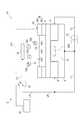
- FIG. 1 is a diagram illustrating the configuration of the pH sensor according to the first embodiment.
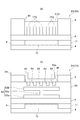
- FIG. 2 is an enlarged view of the measurement ion-sensitive membrane shown in FIG.
- FIG. 3 is a diagram showing the relationship between the voltage to be measured and the membrane voltage.
- Part (a) of FIG. 4 is a diagram schematically showing a membrane electrode.
- Part (b) of FIG. 4 is a diagram showing an equivalent circuit having the configuration shown in part (a) of FIG.
- FIG. 5 is a diagram illustrating the configuration of the pH sensor according to the second embodiment.
- FIG. 6 is a diagram for explaining the operation of the pH sensor of the third embodiment.
- FIG. 7 is a diagram illustrating the configuration of the pH sensor according to the fourth embodiment.
- FIG. 1 is a diagram illustrating the configuration of the pH sensor according to the first embodiment.
- FIG. 2 is an enlarged view of the measurement ion-sensitive membrane shown in FIG.
- FIG. 3 is a diagram showing the relationship between the voltage to be measured and the membrane
- FIG. 8 is a diagram for explaining the operation of the pH sensor according to the fourth embodiment.
- FIG. 9 is a diagram for explaining an operation flow of the pH sensor according to the fourth embodiment.
- FIG. 10 is a diagram illustrating a configuration of a pH sensor according to the first modification.
- FIG. 11 is a graph showing the results of Experimental Example 1 and Reference Example 1.
- FIG. 12 is a diagram schematically illustrating the apparatus configuration in Experimental Example 2 and Reference Example 2.
- FIG. 13 is a graph showing the results of Experimental Example 2 and Reference Example 2.
- FIG. 14 (a) is a diagram showing electrodes provided in the pH sensor of the second modification
- FIG. 14 (b) is a diagram showing electrodes provided in the pH sensor of the third modification.
- FIG. 15A is a diagram showing electrodes provided in the pH sensor of Modification Example 4, and FIG. 15B is a diagram showing electrodes provided in the pH sensor of Modification Example 5.
- FIG. 16A is a diagram showing an electrode provided in the pH sensor of Modification Example 6, and FIG. 16B is a diagram showing an electrode provided in the pH sensor of Modification Example 7.
- FIG. 17A is a diagram illustrating a measurement ISFET included in the pH sensor of the first embodiment
- FIG. 17B is a diagram illustrating a measurement ISFET included in the pH sensor of Modification 8.
- 18A is a diagram showing a measurement ISFET included in the pH sensor of Modification Example 9
- FIG. 18B is a diagram showing a measurement ISFET included in the pH sensor of Modification Example 10.
- FIG. 19A is a diagram showing a measurement ISFET included in the pH sensor of Modification Example 11, and FIG. 19B is a diagram showing a measurement ISFET included in the pH sensor of Modification Example 12.
- the ion concentration measurement apparatus shown in FIG. 1 is arranged on a measurement object 101 that is, for example, soil.
- the ion concentration measuring device is referred to as “pH sensor 1”.
- the pH sensor 1 directly and continuously obtains the concentration of hydrogen ions that are measurement ions 102.
- the hydrogen ion concentration is referred to as “pH”.
- the measurement object 101 includes measurement ions 102 and non-measurement ions 103.
- the measurement ions 102 are exemplified by hydrogen ions as described above.
- Non-measurement ions 103 are exemplified by hydroxide ions and the like.
- the pH sensor 1 includes an ion selective field effect transistor (ISFET).
- the pH sensor 1 including an ISFET connects a material that the measurement ions 102 specifically adsorb to the gate portion of the MOSFET as a sensitive film. And the pH sensor 1 reads the voltage change which generate
- FIG. According to this structure, it is possible to arrange the pH sensor 1 directly on the soil. In addition, according to this configuration, the pH sensor 1 can be reduced in size and increased in accuracy.
- the pH sensor 1 has a measurement ISFET 2 (measurement sensor unit) and a power supply unit 3 as main components.
- the measurement ISFET 2 includes a substrate 4, an insulating film 6, a measurement ion sensitive film 7 (ion trapping film), and a protective film 8.
- the substrate 4 is made of, for example, n-type silicon.
- a part of the substrate 4 is provided with a source 9 and a drain 11.
- the source 9 is p-type.
- the drain 11 is also p-type.
- the source 9 is electrically connected to the substrate 4 via the line L1. According to this connection, the source 9 is at the same potential as the substrate 4.
- the drain 11 is electrically connected to the substrate 4 via a line L 2 having a substrate power supply 12.
- the substrate power supply 12 provides the drain voltage to the measurement ISFET 2.
- the potential difference between the source 9 and the drain 11 is the drain voltage.
- the operation (threshold voltage) of the measurement ISFET 2 is determined by the potential difference between the measurement target power supply 16 and the substrate 4.
- the measurement ISFET 2 is in the ON state, a current flows between the drain 11 and the source 9. Therefore, the voltage of the channel 13 is an intermediate value between the voltage of the drain 11 and the voltage of the source 9.
- the voltage of the substrate power supply 12 is larger than the voltage of the measurement target power supply 16 (threshold voltage ⁇ voltage of the measurement target power supply 16 ⁇ voltage of the substrate power supply 12). As a result, there is a possibility that the measurement ISFET 2 cannot sufficiently suppress the drift described later.
- the measurement membrane power supply 18 it is possible to satisfy both a condition for suppressing drift of an output voltage, which will be described later, and a condition for operating the measurement ISFET 2.
- the condition for suppressing the drift of the output voltage is that the voltage of the measurement membrane power supply 18 is smaller than the voltage of the measurement target power supply 16 (the voltage of the measurement membrane power supply 18 ⁇ the voltage of the measurement target power supply 16).
- the conditions for operating the measurement ISFET 2 are that the threshold voltage is smaller than the voltage of the measurement film power supply 18 and the voltage of the measurement film power supply 18 is smaller than the voltage of the substrate power supply 12 (threshold voltage ⁇ voltage of measurement film power supply 18 ⁇ substrate voltage 12 Voltage).
- the nonuniformity in the measurement ion sensitive membrane 7 is eliminated.
- the voltage of the substrate power supply 12 as the drain 11 voltage can be set to a desired value.
- An insulating film 6 is provided on the main surface of the substrate 4. This main surface includes the main surfaces of the source 9, the drain 11, and the channel 13.
- the insulating film 6 is made of, for example, silicon oxide (SiO 2 ).
- the insulating film 6 is covered with a measurement ion sensitive film 7 and a protective film 8. That is, the measurement ion sensitive film 7 and the protective film 8 are provided on the main surface of the insulating film 6.
- the measurement ion sensitive film 7 is provided on the channel 13 through the insulating film 6. That is, the measurement ion sensitive film 7 functions as a gate in the FET.
- the measurement ion sensitive film 7 is in direct contact with the measurement object 101.
- the measurement ion sensitive film 7 selectively captures the measurement ions 102 included in the measurement target 101.
- the measurement ions 102 are hydrogen ions. Therefore, the measurement ion-sensitive film 7 is made of a material having OH groups on the film surface that promote specific adsorption for hydrogen ions.
- Si 3 N 4 or Ta 2 O 5 may be used for the measurement ion sensitive film 7.
- a protective film 8 is provided on the main surface of the insulating film 6 that is not covered with the measurement ion sensitive film 7.
- a silicon oxide film 8a (SiOx) and a silicon nitride film 8b (SiNx) may be used.
- the power supply unit 3 includes a measurement target electrode 14, a measurement target power supply 16, a measurement membrane electrode 17, a measurement membrane power supply 18, and a power supply control unit 19.
- the measurement target power supply 16 is electrically connected to the measurement target electrode 14 via the line L3.
- the measurement target power supply 16 is electrically connected to the source 9 by a line L4. Therefore, the voltage reference of the measurement target power supply 16 is the potential of the source 9 or the potential of the substrate 4. In the following description, the voltage reference of the measurement target power supply 16 is described as being the potential of the source 9.
- the measurement target electrode 14 and the measurement target power supply 16 keep the difference between the potential of the source 9 and the potential of the measurement target 101 constant. In other words, the measurement target electrode 14 and the measurement target power supply 16 keep the potential of the measurement target 101 constant with respect to the potential of the source 9. In the following description, the difference between the potential of the source 9 and the potential of the measurement target 101 is referred to as “measurement target voltage (V T )”.
- the measurement target voltage (V T ) may be referred to as a reference voltage.
- the measurement target electrode 14 is disposed on the measurement target 101. For example, when the measurement target 101 is soil, the measurement target electrode 14 is disposed on the soil.
- the measurement target electrode 14 applies a measurement target voltage (V T ) to the measurement target 101.
- the measurement target voltage (V T ) is output from the measurement target power supply 16 connected to the measurement target electrode 14.
- the measurement target power supply 16 controls the measurement target voltage (V T ) according to the control signal output from the power supply control unit 19. That is, the measurement target voltage (V T ) is variable.
- the measurement membrane power source 18 is electrically connected to the measurement membrane electrode 17 by a line L5. Further, the measurement membrane power source 18 is electrically connected to the source 9 by a line L6. Therefore, the voltage reference generated by the measurement membrane power supply 18 is the potential of the source 9 or the potential of the substrate 4. The reference of the voltage output from the measurement membrane power supply 18 may be the potential of the measurement target power supply 16.
- the measurement membrane electrode 17 and the measurement membrane power source 18 control the voltage of the measurement ion sensitive membrane 7. That is, the pH sensor 1 according to the embodiment actively controls the voltage of the measurement ion sensitive film 7.
- the voltage of the measurement ion sensitive membrane 7 is the difference between the potential of the measurement object 101 and the potential of the measurement ion sensitive membrane 7. In the following description, the difference between the potential of the measurement object 101 and the potential of the measurement ion sensitive membrane 7 is referred to as “membrane voltage (V F )”.
- the potential of the measurement ion sensitive membrane 7 is the sum of the potential applied from the measurement membrane electrode 17 and the potential generated when the measurement ions 102 are captured by the measurement ion sensitive membrane 7.
- membrane control voltage (V C ) the potential applied from the measurement membrane electrode 17 is referred to as “membrane control voltage (V C )”.
- the reference of the membrane control voltage (Vc) is the potential of the source 9.
- the measurement membrane electrode 17 and the measurement membrane power source 18 control the membrane control voltage (V C ).
- the measurement membrane electrode 17 is disposed inside the measurement ion sensitive membrane 7.
- the measurement membrane electrode 17 is embedded in the measurement ion sensitive membrane 7.
- the measurement membrane electrode 17 has a striped shape. In other words, the measurement membrane electrode 17 has a stripe shape.
- the measurement membrane electrode 17 includes a plurality of electrode ridges 17a.
- the plurality of electrode ridges 17a are electrically connected to each other.
- the plurality of electrode ridges 17a have the same potential.
- the electrode ridge 17 a is in contact with the main surface of the insulating film 6.
- the electrode ridge 17a extends in a predetermined direction. This predetermined direction is orthogonal to the direction of the drain current 200 flowing from the source 9 to the drain 11.
- the electrode ridges 17 a are separated from each other along the direction of the drain current 200. That is, a part of the measurement ion sensitive film 7 and the electrode ridge 17 a are alternately arranged along the direction of the drain current 200. For example, the interval between the adjacent electrode ridges 17a is 600 nm.
- the tip surface of the electrode ridge 17 a is covered with the measurement ion sensitive film 7.
- the tip surface of the electrode ridge 17a is not exposed to the measurement object 101.
- the tip surface of the electrode ridge 17a does not directly contact the measurement object 101.
- the pH sensor 1A is different from the pH sensor 1 of the embodiment in that it does not have the measurement membrane electrode 17 and the measurement membrane power source 18.
- the pH sensor 1A does not actively control the membrane voltage (V F ) of the measurement ion sensitive membrane. In other words, the pH sensor 1A does not independently control the membrane voltage (V F ) of the measurement ion sensitive membrane.
- the rest of the configuration of the pH sensor 1A other than the measurement membrane electrode 17 and the measurement membrane power supply 18 is the same as that of the pH sensor 1.
- the pH sensor 1A applies a measurement target voltage (V T ) from the measurement target electrode 14 to the solution. Therefore, the measurement target 101 has a measurement target voltage (V T ).
- V T measurement target voltage
- the membrane potential changes. Specifically, the membrane potential increases to the positive polarity side due to the positively charged hydrogen ions.
- V F membrane voltage
- the membrane voltage (V F ) is higher than the measurement target voltage (V T ) (V T ⁇ V F ).
- the measurement target 101 is used as a reference, the measurement ion sensitive film 7 appears to be positively charged.
- the hydroxide ion contained in the measurement object 101 has a negative charge.
- hydroxide ions are attracted to the measurement ion sensitive membrane 7. Furthermore, hydroxide ions infiltrate the measurement ion sensitive membrane 7. And hydroxide ion is attracted to the drain voltage which is a voltage higher than measurement object voltage (V T ). As a result, hydroxide ions infiltrate into the measurement ion sensitive membrane 7. According to the infiltration of hydroxide ions into the measurement ion-sensitive membrane 7, the membrane potential is lowered. Infiltration of the hydroxide ion into the measurement ion-sensitive membrane 7 proceeds with time. Then, the infiltration of the hydroxide ions into the measurement ion sensitive film 7 gradually converges.
- the output of the pH sensor 1A is based on the gate voltage (V G ).
- the gate voltage (V G ) is expressed by the following formula (1). That is, the gate voltage (V G ) is the sum of the voltage to be measured (V T ) and the membrane voltage (V F ).
- the membrane voltage (V F ) is based on the potential generated when hydrogen ions are trapped in the measurement ion sensitive membrane 7. Based on this potential, a “pH-dependent voltage (V PH )” is defined.
- the reference of the pH dependent voltage (V PH ) may be, for example, the potential of the source 9.
- Formula (1) is shown as Formula (2).
- drift voltage (V D ) is defined based on the electric potential caused by the infiltrated hydroxide ions.
- drift means that the non-measurement ions 103 permeate the measurement ion-sensitive film 7 with the passage of time, the electric charge is accumulated in the film, and the output voltage of the measurement ISFET 2 changes.
- the reference of the drift voltage (V D ) may be, for example, the potential of the source 9.
- the gate voltage (V G ) is expressed as Equation (3).
- the drift voltage (V D ) depends on the number of infiltrated hydroxide ions. That is, the drift voltage (V D ) increases as the number of invading hydroxide ions increases with time. As a result, even if the voltage to be measured (V T ) and the pH-dependent voltage (V PH ) are constant, the gate voltage (V G ) changes due to fluctuations in the drift voltage (V D ). That is, the output of the pH sensor 1A changes. The change in the output of the pH sensor 1A due to this drift voltage (V D ) is called “drift”.
- the pH sensor 1 suppresses infiltration of the non-measurement ions 103 by actively controlling the membrane voltage (V F ) of the measurement ion-sensitive membrane 7.
- the pH sensor 1 has a measurement membrane electrode 17 embedded in the measurement ion sensitive membrane 7.
- the measurement membrane electrode 17 provides a membrane control voltage (V C ).
- the membrane control voltage (V C ) is a bias voltage that actively sets the reference of the gate voltage (V G ).
- the measurement ISFET 2 operates when the gate voltage (V G ) is equal to or higher than the threshold voltage (V TH ).
- the membrane control voltage (V C ) is set to be equal to or higher than the threshold voltage (V TH ).
- the fluctuation of the voltage based on the membrane control voltage (V C ) is the pH dependent voltage (V PH ).
- the pH dependent voltage (V PH ) corresponds to the captured measurement ion 102.
- the membrane control voltage (V C ) is set to a value that satisfies the following formula (4). In other words, the membrane control voltage (V C ) is smaller than the measurement target voltage (V T ). In other words, the membrane control voltage (V C ) is smaller than the measurement target voltage (V T ). If the measurement object 101 is used as a reference, the measurement ion sensitive film 7 is negatively charged. For example, when the measurement target voltage (V T ) is 500 mV, the membrane control voltage (V C ) is 0 mV.
- the measurement ion sensitive film 7 in which the measurement film electrode 17 is embedded includes a sensitive region S1 and an electrode region S2.
- the sensitive region S1 is formed between the electrode ridges 17a.
- the sensitive region S1 does not include the electrode ridge 17a in the thickness direction of the measurement ion sensitive film 7. According to the sensitive region S1, it is possible to obtain a change in potential generated when the measurement ions 102 are captured on the main surface of the sensitive region S1. This change in potential is a change in pH-induced voltage (V PH ).
- the electrode region S2 includes an electrode ridge 17a.
- the electrode region S2 includes a part of the measurement ion sensitive film 7 in the thickness direction of the measurement ion sensitive film 7 and an electrode ridge 17a.
- V C membrane control voltage
- an electric field indicated by a broken line arrow in FIG. 2 is generated inside the measurement ion sensitive membrane 7.
- the electric field is generated in the portion of the measurement ion sensitive film 7 on the main surface of the electrode ridge 17a and the sensitive region S1.
- the voltage of the solution 303 in the pH sensor 1 is based on the measurement target voltage (V T ) given from the measurement target power supply 16.
- the membrane voltage (V F ) of the measurement ion sensitive membrane 7 is based on the pH-dependent voltage (V PH ) corresponding to the captured measurement ion 102 and the membrane control voltage (V C ) applied from the measurement membrane power source 18.
- the power supply control unit 19 controls the relationship between the measurement target voltage (V T ) output from the measurement target power supply 16 and the membrane control voltage (V C ) output from the measurement membrane power supply 18.
- the power supply control unit 19 controls the measurement membrane power supply 18 so that the polarity of the membrane control voltage (V C ) with respect to the measurement target voltage (V T ) is the same as the polarity of the non-measurement ions 103.
- the non-measurement ions 103 are not attracted to the measurement ion-sensitive membrane 7.
- the drift in the output of the measurement ISFET 2 caused by the non-measurement ions 103 acting on the measurement ion sensitive film 7 can be suppressed. Therefore, the pH sensor 1 can obtain the pH continuously and stably over a long period of time.
- the electrode ridge 17a of the measurement membrane electrode 17 that generates an electric field that suppresses the infiltration of the non-measurement ions 103 is a sensitive region that captures the potential difference between the potential of the measurement target 101 and the potential of the source 9 in the measurement ion sensitive membrane 7. It is provided adjacent to S1.
- the pH sensor 1 controls the potential difference between the measurement object 101 and the measurement ion sensitive film 7. As a result, infiltration of the non-measurement ions 103 into the measurement ion sensitive film 7 is suppressed. Furthermore, it is also possible to keep the potential of the threshold voltage (V TH ) at which pH can be measured. The drift is suppressed by suppressing the infiltration of the non-measurement ions 103. As a result, it is possible to suppress infiltration of the non-measurement ions 103 into the measurement ion-sensitive film 7 while measuring the pH. Therefore, stable measurement can be realized over a long period of time.
- the power supply control unit 19 controls the measurement membrane power supply 18 so that the membrane control voltage (V C ) is smaller than the measurement target voltage (V T ) when the polarity of the non-measurement ions 103 is negative. According to this configuration, drift due to non-measurement ions 103 having a negative polarity can be suppressed.
- the pH sensor 1 further includes a measurement membrane electrode 17 connected to the measurement membrane power source 18 and embedded in the measurement ion sensitive membrane 7.
- An electric field is generated inside the measurement ion sensitive film 7. According to this configuration, the gradient of the electric field can be increased. Accordingly, the non-measurement ions 103 are less likely to approach the measurement ion sensitive film 7. As a result, drift due to the non-measurement ions 103 can be further suppressed.
- the measurement membrane electrode 17 is a stripe-type electrode including a plurality of electrode ridges 17a. According to this configuration, infiltration of the non-measurement ions 103 into the measurement ion-sensitive film 7 can be suppressed. Furthermore, according to this structure, pH can be measured.
- the electrode ridge 17a extends in a direction crossing the direction of the drain current 200 flowing between the source 9 and the drain 11 of the measurement ISFET 2. As shown in FIG. The electrode ridges 17a are separated from each other along the direction of the drain current. According to this configuration, the potential difference generated by the measurement ion sensitive film 7 can be suitably captured.
- Part (b) of FIG. 4 is an equivalent model of an electric circuit having the configuration shown in part (a) of FIG.
- the measurement ion sensitive membrane 7 changes in pH-dependent voltage (V PH ) according to the capture of the measurement ions 102.
- the gate voltage (V G ) changes (see formula (3)).
- the ease of drain current flow that is, electric resistance
- the configuration shown in part (a) of FIG. 4 assumes that a plurality of resistance components R are connected in series in the electrical connection between the source 9 and the drain 11. Can be modeled.
- the resistance component R corresponds to the sensitive region S1 that does not include the electrode ridge 17a.
- the pH sensor 1A of the second embodiment will be described with reference to FIG.
- the pH sensor 1A of the second embodiment is different from the pH sensor 1 of the first embodiment in that the measurement membrane power supply 18 and the measurement membrane electrode 17 are not provided.
- the other configuration of the pH sensor 1A is the same as the configuration of the pH sensor 1 according to the first embodiment.
- the operation in which the pH sensor 1A does not control the membrane voltage (V F ) is exemplified.
- the infiltration of the non-measurement ions 103 is based on the difference between the measurement target voltage (V T ) and the membrane voltage (V F ). Therefore, the condition under which infiltration can be suppressed may be satisfied by actively controlling the measurement target voltage (V T ).
- the pH sensor 1A of the second embodiment suppresses infiltration of the non-measurement ions 103 by actively controlling the measurement target voltage (V T ).
- the power supply control unit 19 of the pH sensor 1A controls the measurement target voltage (V T ) output from the measurement target power supply 16.
- the power supply control unit 19 performs a first operation.
- the first measurement target voltage (V T1 ) is provided to the measurement target 101 via the measurement target electrode 14.
- the first operation is continued for a predetermined time set in advance.
- an output voltage is obtained from the measurement ISFET 2. Therefore, the first operation is a measurement operation.
- the output voltage depends on the degree of trapping of the measurement ions 102 on the measurement ion sensitive film 7.
- the first measurement target voltage (V T1 ) is larger than the threshold voltage (V TH ) of the measurement ISFET 2.
- the relationship between the first measurement target voltage (V T1 ) and the membrane voltage (V F ) is expressed by Expression (5).
- the membrane voltage (V F ) is larger than the first measurement target voltage (V T1 ).
- the power control unit 19 After the elapse of the predetermined time, the power control unit 19 performs the second operation.
- the power supply control unit 19 provides the second measurement target voltage (V T2 ) to the measurement target 101 via the measurement target electrode 14.
- V T2 the second measurement target voltage
- the difference between the voltage of the drain 11 electrode and the voltage of the source 9 electrode is reduced.
- the electrode of the drain 11 and the electrode of the source 9 are set to the same potential.
- the difference between the voltage of the drain 11 electrode and the voltage of the substrate 4 electrode is reduced.
- the electrode of the drain 11 and the electrode of the substrate 4 are set to the same potential.
- the second measurement target voltage (V T2 ) is the same potential as the source voltage (V S ).
- this state is a state in which the source 9 is directly connected to the measurement target electrode 14.
- the gate voltage (V G ) does not satisfy the threshold voltage (V TH ) of the measurement ISFET 2. Therefore, the output from the measurement ISFET 2 cannot be obtained.
- the relationship between the second measurement target voltage (V T2 ) and the membrane voltage (V F ) is expressed by Expression (6).
- the measurement target voltage (V T ) and the membrane voltage (V F ) have the same potential.
- V T the measurement target voltage
- V F the membrane voltage
- a pH sensor 1B of the third embodiment will be described with reference to FIG.
- the device configuration of the pH sensor 1B is the same as the device configuration of the pH sensor 1.
- the operation of the pH sensor 1B is different from that of the pH sensor 1.
- the pH sensor 1B sets the measurement target voltage (V T ) and the membrane voltage (V F ) to the same potential as a mode for suppressing the infiltration of the non-measurement ions 103.
- the pH sensor 1B reduces the difference between the measurement target voltage (V T ) and the membrane voltage (V F ) as a mode for suppressing the infiltration of the non-measurement ions 103.
- FIG. 6A shows the relationship between the voltage to be measured (V T ) (graph G6a) and the membrane voltage (V F ) (graph G6b).
- the vertical axis represents voltage.
- the horizontal axis indicates time.
- the power supply control unit 19 of the pH sensor 1B performs an operation (suppression operation) that makes the measurement target voltage (V T ) and the membrane voltage (V F ) the same potential, and the measurement target voltage (V T ) and the membrane voltage (V F ) And the operation (measuring operation) to be different.
- the power supply control unit 19 controls the measurement target power supply 16 so that the measurement target voltage (V T ) is constant (see graph G6a).
- the power supply control unit 19 controls the measurement membrane power supply 18 so that the measurement target voltage (V T ) and the membrane voltage (V F ) are different from each other (V T > V F ) (graph). (See section K1 of G6b).
- the measurement operation is executed by this control. More specifically, the membrane voltage (V F ) of the measurement membrane power supply 18 is controlled by the membrane control voltage (V C ) provided to the measurement ion sensitive membrane 7. As a result, an output voltage is obtained as shown in part (b) of FIG.
- the suppression operation is executed by this control. In this case, an output voltage cannot be obtained as shown in part (b) of FIG.
- the pH sensor of the fourth embodiment employs a configuration that can reduce the influence of drift and obtain more data.
- the pH sensor 1C includes a measurement ISFET 2, a correction ISFET 2C (correction sensor unit), a power supply unit 3C, and a data processing unit 30.
- the pH sensor 1C uses the measurement ISFET 2 to obtain more output. However, this output includes drift effects. Therefore, the pH sensor 1C corrects the drift component included in the output of the measurement ISFET 2 using the output of the correction ISFET 2C. According to this configuration, it is possible to grasp the progress of drift. In addition, data for correcting drift can be acquired. Furthermore, according to this configuration, measurement for a longer period is possible.
- the measurement ISFET 2 and the correction ISFET 2C each have the same configuration as the measurement ISFET 2 of the first embodiment.
- the power supply unit 3C includes a measurement target power supply 16, a measurement film power supply 18, a correction film power supply 18C, and substrate power supplies 12 and 12C.
- the correction film power source 18C is connected to the correction film electrode 17C.
- the correction film electrode 17C is embedded in the correction ion sensitive film 7C included in the correction ISFET 2C.
- the data processing unit 30 is connected to the measurement ISFET 2 via the voltage sensor 31.
- the data processing unit 30 is connected to the correction ISFET 2C via the voltage sensor 32.
- the data processing unit 30 calculates the pH of the measurement target 101 based on the output voltages of the measurement ISFET 2 and the correction ISFET 2C. More specifically, the data processing unit 30 corrects the drift component included in the output voltage of the measurement ISFET 2 using the output voltage of the correction ISFET 2C. Then, the data processing unit 30 obtains the pH of the measurement object 101 using the corrected output voltage of the measurement ISFET 2.
- the data processing unit 30 is realized, for example, by executing a program described so as to perform the following operation in a computer such as a personal computer or a microcomputer.
- the data processing unit 30 receives data relating to the output voltage from the measurement ISFET 2 and the correction ISFET 2C. These connection modes are not particularly limited.
- the data processing unit 30 may be wired to the measurement ISFET 2 and the correction ISFET 2C.
- the data processing unit 30 may be wirelessly connected to the measurement ISFET 2 and the correction ISFET 2C. Further, the data processing unit 30 may be connected to the measurement ISFET 2 and the correction ISFET 2C via an Internet line or the like. Further, data relating to the output voltage may be temporarily recorded on a data recording medium connected to the measurement ISFET 2 and the correction ISFET 2C. Data relating to the output voltage may be provided to the data processing unit 30 via the data recording medium.
- the operation of the pH sensor 1C is performed by the power control unit 19B and the data processing unit 30.
- the pH sensor 1C is installed on the measurement object 101 (step T10). At this time, the measurement ion sensitive film 7 of the measurement ISFET 2 and the correction ion sensitive film 7C of the correction ISFET 2C touch the same measurement object 101.
- the output characteristics of the measurement ISFET 2 and the correction ISFET 2C are known.
- the output characteristic may include a change in output voltage of the measurement ISFET 2 or the like with respect to a change in pH.
- the output characteristic may include an amplification factor of a circuit connected to the measurement ISFET 2.
- an initial state value at the start of measurement is obtained (step T20).
- the initial state value may include the ion concentration, the output voltage (V M ) of the measurement ISFET 2, and the output voltage (V R ) of the correction ISFET 2C.
- the ion concentration may be obtained using the measurement ISFET 2.
- the ion concentration may be obtained using another ion concentration measuring device. If the initial state value at the start of measurement is known, step T20 may be omitted.
- Measurement data and correction data are acquired (step T30).
- the power supply control unit 19B controls the measurement target power supply 16 to maintain the measurement target voltage (V T ) at a constant value (see the graph G8a in FIG. 8A).
- the power supply control unit 19B repeatedly executes control for making the measurement ISFET 2 a measurement operation and control for making the suppression operation (see the graph G8b in FIG. 8A). For example, in the measurement ISFET 2, the measurement operation for 15 seconds and the suppression operation for 30 minutes are repeated.
- the power supply control unit 19B controls the correction ISFET 2C. Specifically, the power supply control unit 19B repeatedly executes the control for setting the correction ISFET 2C as the measurement operation and the control for the suppression operation (see the part graph G8c in FIG. 8B).
- the cycle of the measurement operation and the suppression operation of the correction ISFET 2C is different from the cycle of the measurement ISFET 2.
- the pH sensor 1C corrects again when the measurement operation of the measurement ISFET 2 and the measurement operation of the correction ISFET 2C are performed simultaneously with the measurement operation of the measurement ISFET 2 of the nth time (n is an integer of 2 or more).
- the measurement operation of ISFET 2C is executed.
- the pH sensor 1C uses the sign (n) as a parameter for counting the measurement operation of the measurement ISFET 2.
- the measurement operation of the correction ISFET 2C is executed again.
- the correction ISFET 2C continues to maintain the suppression operation.
- the conditions such as are illustrative and do not limit the contents of the present invention.
- the measurement ISFET 2 may be operated while switching between the suppression operation for 30 minutes and the measurement operation for 15 seconds.
- the correction ISFET 2C is operated while switching between a continuous suppression operation for one month and a measurement operation for 15 seconds.
- the operation timing is controlled so that the measurement ISFET 2 also performs the measurement operation at the same time.
- the operation is switched between the measurement operation and the suppression operation.
- the measurement ISFET 2 may always be operated as a measurement operation.
- the progress of drift can be delayed by switching the measurement ISFET 2 between the measurement operation and the suppression operation. Therefore, it is possible to continue measuring the ion concentration over a longer period.
- Step T40 includes at least the following steps T41 to T44.
- the relationship between drift and measurement integration time can be predicted to some extent. Based on this predictable time range, the timing for obtaining the output voltage (V R ) of the correction ISFET 2C may be determined.
- the ion concentration measurement device may not have the measurement ISFET 2.
- the pH sensor 1D may have a simple structure.
- the pH sensor 1D includes a printed circuit board 22, a measurement ion sensitive film 2D, a measurement target electrode 14D, and a measurement target power source 16D.
- the printed circuit board 22 has a plate electrode 24 connected to the voltmeter 20.
- the measurement ion sensitive film 2D is provided on the plate electrode 24.
- An electrode 25 connected to the power source 21 is embedded in the measurement ion sensitive film 2D.
- the measurement target voltage (V T ) of the measurement target 101 and the membrane voltage of the measurement ion-sensitive membrane 2D are measured by the power source 21 and the electrode 25 as in the pH sensor 1 according to the first embodiment.
- the relationship between (V F ) and the desired relationship can be controlled. Therefore, by controlling the voltage relationship so that the non-measurement ions 103 do not infiltrate into the measurement ion-sensitive membrane 2D, the occurrence of drift due to the infiltration of the non-measurement ions 103 can be suppressed.
- the non-measurement ions 103 have a negative charge.
- Non-measurement ions 103 may have a positive charge.
- the power supply control unit 19 controls at least one of the measurement target power supply 16 and the measurement membrane power supply 18 so that the membrane control voltage (V C ) is larger than the measurement target voltage (V T ). According to this configuration, drift due to non-measurement ions 103 having a positive polarity can be suppressed.
- the application of the ion concentration measuring device is not limited to soil pH measurement.
- the ion concentration measurement device may be applied to measurement of pH measurement in a culture medium or concrete.
- the application of the ion concentration measuring device is not limited to pH measurement.
- it can be suitably applied to a sensor that adsorbs and desorbs ions, such as a potassium (K) ion sensor in soil.
- K potassium
- FIG. 11 shows the output of the pH sensor 1.
- the horizontal axis represents the elapsed time.
- the vertical axis represents the membrane voltage (V F ).
- the membrane voltage (V F ) at the start of measurement was about 65 mV.
- the membrane voltage (V F ) after 6 hours from the start of measurement was also about 65 mV. That is, no drift was confirmed. Therefore, it was found that drift can be suppressed by satisfying the condition shown in Expression (4).
- Reference Example 1 In Reference Example 1, it was confirmed that the drift could not be suppressed when it was not a condition satisfying Equation (4). That is, it was confirmed that drift occurs when the membrane voltage (V F ) is larger than the measurement target voltage (V T ).
- the conditions of Reference Example 1 are as follows.
- the membrane voltage (V F ) is the sum of the pH dependent voltage (V PH ) and the membrane control voltage (V C ). Therefore, the membrane voltage (V F ) is larger than 0 V that is the membrane control voltage (V C ).
- the measurement object 101 was a solution having a predetermined pH.
- the solution includes hydrogen ions as measurement ions 102 and hydroxide ions as non-measurement ions 103.
- V C Membrane control voltage
- V T Measurement target voltage
- S-drain voltage 1.5V.
- Solution pH 6.86.
- Measurement ion Hydrogen ion.
- Non-measurement ion hydroxide ion.
- pH sensor type Depletion type n-channel type.
- the membrane voltage (V F ) at the start of measurement was about 50 mV.
- the membrane voltage (V F ) after 6 hours from the start of measurement was about 45 mV. That is, when the membrane voltage (V F ) is larger than the measurement target voltage (V T ), a drift of about 0.83 mV / h was confirmed.
- the pH sensor 300 includes a measurement target electrode 301, a measurement target power supply 302, a measurement ISFET 304, and an ammeter 306.
- One end of the measurement target power supply 302 is grounded.
- the other end of the measurement target power supply 302 is connected to the measurement target electrode 301 via the switch 307.
- the source of the measurement ISFET 304 is connected to the measurement target electrode 301 via the switch 308.
- the source of the measurement ISFET 304 is connected to a predetermined potential 313 via the switch 309. Further, the drain of the measurement ISFET 304 is connected to the ammeter 306 via the switch 312.
- the drain of the measurement ISFET 304 is connected to the source via the switch 311.
- the pH sensor 300 can switch between the measurement operation and the suppression operation by the operation of the switches 307, 308, 309, 311 and 312. For example, as shown in part (a) of FIG. 12, the pH sensor 300 performs a measurement operation by turning on the switches 307, 309, and 312 and turning off the switches 308 and 311. As shown in part (b) of FIG. 12, the pH sensor 300 performs the suppression operation by turning off the switches 307, 309, and 312 and turning on the switches 308 and 311.
- the measurement target electrode 301 has the same potential as the measurement ISFET 304. A cycle including a 1-minute measurement operation and a 12-hour suppression operation was repeated a plurality of times to obtain an output voltage of the measurement ISFET 304.
- the experimental conditions other than the above are as follows.
- Graph G13a in FIG. 13 shows the result of Experimental Example 2. According to the graph G13a, the degree of drift was ⁇ 0.1 mV / h. That is, it was found that the degree of drift can be suitably reduced by introducing the suppression operation.
- Reference Example 2 For comparison with Experimental Example 2, the experiment of Reference Example 2 was also performed. In Reference Example 2, an output was obtained when the measurement operation was continued without switching to the suppression operation. Other experimental conditions are the same as in Experimental Example 2.
- the graph G13b in FIG. 8 shows the result of Reference Example 2. According to Reference Example 2, it was confirmed that a clear drift occurred with the passage of time. For example, when focusing on the period from 60 hours to 100 hours, the drift of Reference Example 2 was ⁇ 0.63 mV / h.
- the pH sensor of the present invention may further employ the following modifications.
- the measurement membrane electrode is not limited to the stripe type shown in FIG.
- the electrodes 51A, 51B, 51C, 51E, 51F and the electrode unit 51D of the modified examples 2 to 7 are used for controlling the potentials of the measurement ion sensitive membrane 7 and the ion selective membranes 61F, 61G, 65K, 65L described later. Also good.
- the electrode 51 ⁇ / b> A of the second modification has a plurality of electrode ridges 52 and a ridge connection part 53 that electrically connects the electrode ridges 52 to each other.
- the electrode 51A of the second modification is a so-called comb-shaped electrode.
- the base end of the electrode ridge 52 is connected to the ridge connection portion 53.
- the electrode ridge 52 extends linearly in a direction away from the ridge connection portion 53.
- the electrode ridge 52 is disposed so as to intersect the direction from the source 9 to the drain 11.
- Such an electrode 51 ⁇ / b> A can control the potential of the measurement ion-sensitive film 7 or the like with the same electrode. Further, according to the electrode 51A, it is possible to capture the pH change with high sensitivity in the current path.
- the electrode 51 ⁇ / b> B of Modification 3 includes a plurality of electrode ridges 52 ⁇ / b> B and a ridge connection part 53 that electrically connects the electrode ridges 52 ⁇ / b> B to each other.
- the base end of the electrode ridge 52 ⁇ / b> B is connected to the ridge connection portion 53.
- the electrode ridge 52 ⁇ / b> B extends in a direction away from the ridge connection portion 53.
- the electrode 51B of the third modification does not extend linearly in the direction away from the ridge connecting portion 53.
- the electrode 51B includes a portion extending in a direction away from the ridge connection portion 53 and a portion extending in a direction intersecting with the direction away from the ridge connection portion 53. These portions are alternately arranged along a direction away from the ridge connection portion 53. Such an electrode 51B can efficiently apply a voltage to a measurement object in a non-uniform state.
- the electrode 51 ⁇ / b> C of Modification 4 includes a plurality of electrode ridges 52 ⁇ / b> C and a ridge connection part 53 ⁇ / b> C that electrically connects the electrode ridges 52 ⁇ / b> C to each other.
- the electrode ridge 52C is disposed so as to extend linearly in the direction from the source 9 to the drain 11. That is, in the electrode 51C of the modification example 4, the direction of the electrode ridge 52C is different from the direction of the electrode ridge 52 of the modification example 2.
- Such an electrode 51C can form a uniform electric field distribution with respect to the direction of current flow. As a result, the electrode 51C can reduce noise at the interface between the silicon and the oxide film.
- the electrode unit 51D of Modification 5 has a pair of electrodes 51a and 51b.
- the electrodes 51a and 51b are electrically insulated from each other.
- a power source 18 is connected to each of the electrodes 51a and 51b.
- the electrode 51a includes a plurality of electrode ridges 52a and a ridge connection portion 53a that electrically connects the electrode ridges 52a to each other.
- the electrode 51b includes a plurality of electrode ridges 52b and a ridge connection portion 53b that electrically connects the electrode ridges 52b to each other.
- the electrode ridges 52 a and 52 b are arranged so as to intersect the direction from the source 9 to the drain 11.
- One electrode ridge 52b of the other electrode 51b is disposed between the pair of electrode ridges 52a of the one electrode 51a. That is, the electrode ridges 52a of one electrode 51a and the electrode ridges 52b of the other electrode 51b are alternately arranged from the source 9 to the drain 11.
- Such an electrode unit 51D can apply different voltages to the electrodes 51a and 51b. As a result, the electrode unit 51D can separately perform an operation for suppressing infiltration of ions and an operation for controlling the threshold voltage of the sensor.
- the direction in which the electrode ridges 52a and 52b extend may be the same direction as the current as shown in FIG.
- the electrode 51E of Modification 6 includes a plurality of electrode ridges 52E and a plurality of ridge coupling portions 54E that electrically connect the electrode ridges 52E to each other.
- the electrode ridge 52E is disposed so as to intersect the direction from the source 9 to the drain 11.
- the ridge coupling portion 54 ⁇ / b> E is disposed along the direction from the source 9 to the drain 11. That is, the electrode ridge 52E is orthogonal to the ridge connecting portion 54E.
- the electrode 51E has a lattice shape in plan view.
- a portion surrounded by the electrode ridge 52E and the ridge connecting portion 54E is used as a sensing hole.
- Such an electrode 51E can apply an electric field from four directions so as to surround a sensing hole. As a result, the electrode 51E can apply a voltage for more efficiently suppressing ion infiltration.
- the electrode 51 ⁇ / b> F of the modified example 7 includes a plurality of electrode chips 55 and wirings 56.
- the plurality of electrode tips 55 are separated from each other along the direction from the source 9 to the drain 11.
- the plurality of electrode chips 55 are also separated from each other in the direction intersecting with the direction from the source 9 to the drain 11.
- a wiring 56 is electrically connected to each of the plurality of electrode chips 55.
- the plurality of electrode chips 55 receive a voltage from the power source 18 through the wiring 56.
- Such an electrode 51F can apply an electric field for suppressing infiltration of ions in a wide range. Moreover, according to the electrode 51F, replacement
- the measurement sensor unit is not limited to the structure shown in FIG.
- the measurement sensor unit may employ the measurement ISFETs 2F, 2G, 2H, 2K, and 2L of Modifications 8 to 13 shown in FIGS.
- FIGS. 17, 18 and 19 show only the measurement ISFETs 2, 2F, 2G, 2H, 2K, and 2L. That is, in FIG. 17, FIG. 18, and FIG. 19, illustration of other components constituting the pH sensors 1, 1F, 1G, 1H, 1K, and 1L is omitted.
- the pH sensor 1 includes a measurement ISFET 2 and a power supply unit 3 (see FIG. 1 and the like).
- the measurement ISFET 2 includes a substrate 4, an insulating film 6, a measurement ion sensitive film 7, and a protective film 8.
- An insulating film 6 that is a gate oxide film is provided on the main surface of the substrate 4. This main surface includes the main surfaces of the source 9, the drain 11, and the channel 13.
- the insulating film 6 is made of, for example, silicon oxide (SiO 2 ).
- the insulating film 6 is covered with the measurement ion sensitive film 7 and the protective film 8.
- the measurement ion sensitive film 7 is, for example, a hydrogen sensitive film sensitive to hydrogen ions.
- the measurement ion sensitive film 7 is formed on the channel 13 via the insulating film 6.
- the protective film 8 is not provided on the main surface of the measurement ion sensitive film 7. In other words, the measurement ion sensitive film 7 is exposed from the opening 8 h provided in the protective film 8. That is, the measurement ion sensitive film 7 is in direct contact with the measurement object 101.
- the electrode 17 is disposed inside the measurement ion sensitive film 7. More specifically, the electrode 17 is embedded in the measurement ion sensitive film 7.
- the configuration of the electrode 17 may be striped, or may be the configuration shown in the above-described modified examples 2 to 7.
- the tip surface of the electrode 17 is covered with the measurement ion sensitive film 7. The tip surface of the electrode 17 is not exposed to the measurement target 101.
- the pH sensor 1F of the modified example 8 includes a measurement ISFET 2F and a power supply part 3 (see FIG. 1 and the like).
- the pH sensor 1F of Modification 8 further includes an ion selective membrane 61F (ion trapping membrane).
- the ion selective membrane 61F captures ions based on a principle different from that of the measurement ion sensitive membrane 7E.
- the measurement ion-sensitive film 7E captures ions by utilizing the property of specific adsorption of ions.
- the ion selective membrane 61F captures ions in small physical holes.
- the ion selective membrane 61F has a physically small hole (bore). The diameter of this hole corresponds to the ion radius of the ion to be detected. That is, desired ions can be selectively detected by setting the diameter of the hole to a predetermined dimension.
- the measurement target of the ion selective membrane 61F includes potassium (K) ions, sodium (Na) ions, magnesium (Mg) ions, nitrate nitrogen, phosphorus (P) ions, and the like.
- the ion selective membrane 61F is provided on the measurement ion sensitive membrane 7. More specifically, the ion selective film 61F is provided on the main surface of the measurement ion sensitive film 7 exposed from the opening 8h of the protective film 8. That is, the insulating film 6, the measurement ion sensitive film 7, and the ion selective film 61F are laminated on the channel 13 of the substrate 4.
- the pH sensor 1F of Modification 8 is different from the pH sensor 1 of Modification 8 in that it has an ion selective membrane 61F. According to the configuration of the modification 8, a sensor can be easily formed by adding the ion selective film 61F to the element that has completed the manufacturing process of the measurement ISFET 2 shown in FIG.
- the ion to be selected is selected. Drift may occur when ions having a polarity opposite to the polarity of the liquid infiltrate the membrane. When drift occurs, the detection potential shifts.
- the pH sensor 1F of Modification 8 includes an electrode 17 for controlling the potential. As a result, the pH sensor 1F of the modification 8 can suppress the occurrence of drift.
- the pH sensor 1G of the modification 9 includes a measurement ISFET 2G and a power supply part 3 (see FIG. 1 and the like).
- the measurement ISFET 2G includes a substrate 4, an insulating film 6, a protective film 8, and an ion selective film 61G. That is, the pH sensor 1 ⁇ / b> G according to Modification 9 does not include the measurement ion sensitive film 7. Accordingly, the pH sensor 1G captures ions that are selection targets by the ion selective membrane 61G.
- An insulating film 6 which is a gate oxide film is provided on the main surface of the substrate 4.
- a protective film 8 and an ion selective film 61G are provided on the main surface of the insulating film 6.
- the ion selective film 61 ⁇ / b> G is provided on the channel 13 of the substrate 4.
- An electrode 17G is embedded in the ion selective film 61G.
- the pH sensor 1G of Modification 9 is different from the pH sensor 1 of the first embodiment in that the measurement ion sensitive membrane 7 of the pH sensor 1 of the first embodiment is replaced with an ion selective membrane 61G.
- the ion selective film 61G is provided directly on the insulating film 6.
- the configuration of the modification 9 can strongly apply the electric field of the electrode 17G to the ion selective film 61G.
- the pH sensor 1H of the modified example 10 includes a measurement ISFET 2H and a power supply part 3 (see FIG. 1 and the like).
- the measurement ISFET 2H includes a substrate 4, an insulating film 6, a measurement ion sensitive film 7H, and a protective film 8. Further, the measurement ISFET 2H includes a buried film 62, a detection unit 63, and an electrode 64.
- An insulating film 6 which is a gate oxide film is provided on the main surface of the substrate 4.
- a buried film 62 is provided on the main surface of the insulating film 6.
- a protective film 8 and a part of the measurement ion sensitive film 7H are provided on the main surface of the protective film 8.
- another part of the measurement ion sensitive film 7H is provided on the main surface of the protective film 8.
- the step of providing the buried film 62 is an additional step for providing a detection film for detecting ions in the uppermost layer portion of the semiconductor element. This process is particularly effective for an element including multilayer wiring.
- a detection unit 63 and an electrode 64 are embedded in the embedded film 62.
- the embedded film 62 is a film different from the measurement ion sensitive film 7H. That is, the electrode 64 is not embedded in the measurement ion sensitive film 7H.
- the electrode 64 is provided on the main surface side of the buried film 62. More specifically, the buried film 62 has a measurement main surface 62 a exposed from the opening 8 h of the protective film 8. The upper surface of the electrode 64 is exposed from the measurement main surface 62a. The upper surface of the electrode 64 is in contact with the measurement ion sensitive film 7H. The lower surface of the electrode 64 does not reach the insulating film 6.
- a detection unit 63 is provided in a region between the electrode 64 and the insulating film 6.
- the detector 63 receives the change in the potential of the measurement ion sensitive film 7H caused by the change in ions, and transmits this change in potential to the insulating film 6.
- the detection unit 63 is an expansion type sensing unit.
- the detection unit 63 is provided on the channel 13 of the substrate 4. That is, the insulating film 6, the detection unit 63, the electrode 64, and the measurement ion sensitive film 7H are laminated on the channel 13 of the substrate 4.
- the detecting unit 63 includes a first part 63a, a second part 63b, and a connecting part 63c.
- the first portion 63 a is in contact with the main surface of the insulating film 6.
- the first portion 63 a covers the channel 13. Near the center of the first portion 63a, the base end of the connecting portion 63c is provided.
- the connecting portion 63c extends from the first portion 63a toward the electrode 64.
- a second portion 63b is provided at the tip of the connecting portion 63c. Similar to the first portion 63a, the second portion 63b covers the channel 13.
- a part of the buried film 62 exists between the second portion 63 b and the electrode 64.
- part of the buried film 62 exists between the first portion 63a and the second portion 63b.
- the pH sensor 1H of Modification 10 has an embedded film 62, and an electrode 64 and a detection unit 63 are embedded in the embedded film 62. According to such a structure, the level
- the pH sensor 1 ⁇ / b> K of the modification 11 includes a measurement ISFET 2 ⁇ / b> K and a power supply unit 3 (see FIG. 1 and the like).
- the pH sensor 1K of Modification Example 11 further includes an ion selective membrane 65K.
- the ion selective membrane 65K is provided on the main surface of the measurement ion sensitive membrane 7H.
- the height of the measurement ion sensitive film 7 ⁇ / b> H differs between the portion provided on the buried film 62 and the portion provided on the protective film 8. That is, the film thickness of the measurement ion sensitive film 7H is constant and includes a step corresponding to the height of the protective film 8.
- the ion selective membrane 65K has no step.
- the main surface of the ion selective membrane 65K is generally flat. That is, the film thickness of the ion selective film 65K is not constant.
- the film thickness of the region formed on the buried film 62 in the ion selective film 65K is larger than the film thickness of the region formed on the protective film 8.
- the pH sensor 1K of the modification 11 has an ion selective membrane 65K in addition to the configuration of the pH sensor 1H of the modification 10. According to such a configuration, after the measurement ISFET 2H shown in part (b) of FIG. 18 is manufactured, the type of ions to be detected can be changed.
- the pH sensor 1 ⁇ / b> L of the modification 12 includes a measurement ISFET 2 ⁇ / b> L and a power supply unit 3 (see FIG. 1 and the like).
- the pH sensor 1L of the modified example 12 has a configuration in which the measurement ion sensitive membrane 7H is replaced with the ion selective membrane 65L in the pH sensor 1H of the modified example 10.
- the ion selective film 65 ⁇ / b> L is provided on the main surfaces of the buried film 62 and the protective film 8. That is, the ion selective film 65 ⁇ / b> L is in contact with the buried film 62 and the protective film 8. More specifically, the ion selective membrane 65L is in contact with the electrode 64. The main surface of the ion selective membrane 65L has no step. That is, the film thickness of the ion selective film 65L is not constant. The film thickness of the region in contact with the buried film 62 in the ion selective film 65 ⁇ / b> L is larger than the film thickness in contact with the protective film 8.
- the pH sensor 1L of the modified example 12 has an ion selective membrane 65L instead of the measurement ion sensitive membrane 7H of the pH sensor 1H of the modified example 10. According to such a configuration, the electric field caused by the electrode 64 can be strongly transmitted to the ion selective film 65L.
Landscapes
- Life Sciences & Earth Sciences (AREA)
- Chemical & Material Sciences (AREA)
- Health & Medical Sciences (AREA)
- Physics & Mathematics (AREA)
- Molecular Biology (AREA)
- Chemical Kinetics & Catalysis (AREA)
- Electrochemistry (AREA)
- Analytical Chemistry (AREA)
- Biochemistry (AREA)
- General Health & Medical Sciences (AREA)
- General Physics & Mathematics (AREA)
- Immunology (AREA)
- Pathology (AREA)
- Microelectronics & Electronic Packaging (AREA)
- Engineering & Computer Science (AREA)
- Investigating Or Analyzing Materials By The Use Of Electric Means (AREA)
Abstract
pHセンサ1は、計測イオン102と非計測イオン103とを含む計測対象101に設置されて、計測イオン102の濃度を得る。pHセンサ1は、計測対象101の計測対象電圧(VT)を制御する計測対象電源16と、計測イオン102を選択的に捕捉して、捕捉した計測イオン102の数に対応するpH依存電圧(VPH)を生じさせる計測イオン感応膜7を含む計測ISFET2と、計測イオン感応膜7の膜制御電圧(VC)を制御する計測膜電源18と、計測対象電源16及び計測膜電源18のそれぞれから出力される電圧の大きさを制御する電源制御部19と、を備える。
Description
本発明は、イオン濃度計測装置に関する。
水素イオン指数(以下「pH」と呼ぶ)は、農業分野及び水質検査分野において重要な物理量である。pHを計測する手段として、リトマス試験紙を用いる手段、ガラス電極を用いる手段及びイオン選択性電界効果型トランジスタ(Ion Sensitive Field Effect Transistor:ISFET)を用いる手段が知られている。例えば、非特許文献1は、ISFETに関する技術を開示する。
タダユキ マツオ、マサヨシ エサシ(TADAYUKI MATSUO, MASAYOSHI ESASHI)、「ISFETの製造方法」(METHODS OF ISFET FABRICATION)、センサー・アンド・アクチュエーターズ(Sensors and Actuators)、 オランダ(Netherlands)、エルゼビア セコイア エス・エー(Elsevier Sequoia S.A.)、1981年、pp.77-96。
シャフリヤール ヤマス、スコット コリン、ローズマリー エル スミス(Shahriar Jamasb, Scott Collins, Rosemary L. Smith)、「pH ISFETにおけるドリフトの物理モデル」(A Physical model for drift in pH ISFETs)、センサー・アンド・アクチュエーターズ(Sensors and Actuators)、1998年、pp.146-155。
例えば、農業分野においては、作物ごとに適した土壌のpHの値が存在することが知られている。そこで、土壌などの細かな粒子が混在する対象物のpHを長期間に亘って連続的に計測する技術が望まれている。リトマス試験紙を用いる計測手段は、連続的な計測には不向きである。ガラス電極を用いる手段は、ガラス電極と比較電極とを有する。比較電極は、被計測液と電極との電気的接続を確保するための液落部を有する。この液落部は、詰まりやすい。非特許文献2は、ISFETの出力が経時的な特性変動(ドリフト)を含むことを開示する。従って、いずれの手段においても、イオン濃度に応じた信号を長期間に亘って連続的に安定して得ることが難しかった。
本発明は、イオン濃度を長期間に亘って連続的に安定して得ることが可能なイオン濃度計測装置を提供する。
本発明の一形態のイオン濃度計測装置は、計測イオンと非計測イオンとを含む計測対象に設置されて、計測イオンの濃度を得る。イオン濃度計測装置は、計測対象の電圧を制御する計測対象電源と、計測イオンを選択的に捕捉して、捕捉した計測イオンの数に対応する電圧を生じさせる計測イオン感応膜を含む計測センサ部と、計測イオン感応膜の電圧を制御する計測膜電源と、計測対象電源及び計測膜電源のそれぞれから出力される電圧の大きさを制御する電源制御部と、を備える。
このイオン濃度計測装置では、計測対象の計測対象電圧は計測対象電源から与えられる電圧に基づく。計測イオン感応膜の電圧は、捕捉した計測イオンに対応する電圧と計測膜電源から与えられる計測膜電圧とに基づく。電源制御部は、計測対象電源が出力する電圧と計測膜電源が出力する電圧との関係を制御する。例えば、電源制御部が計測対象電源及び計測膜電源を制御することにより、計測対象電圧に対する計測膜電圧の極性を非計測イオンの極性と同じにすることができる。また、電源制御部の制御によれば、計測対象電圧と計測膜電圧との差分を小さくすることもできる。このような計測対象電圧と計測膜電圧との関係によれば、非計測イオンを計測イオン感応膜に引き寄せることがない。その結果、非計測イオンが計測イオン感応膜に作用することで生じる計測イオン選択感応膜の出力におけるドリフトを抑制することができる。従って、イオン濃度計測装置は、イオン濃度に応じた信号を長期間に亘って連続的に安定して得ることができる。
一形態において、イオン濃度計測装置は、計測膜電源に接続され、計測イオン感応膜に埋め込まれた計測膜電極をさらに備えてもよい。計測イオン感応膜の内部には、電界が生じる。この構成によれば、当該電界の勾配を大きくすることができる。電界の勾配が大きくなると、非計測イオンが計測イオン感応膜により近づきにくくなる。その結果、非計測イオンに起因するイオン選択性電界効果型トランジスタの出力が含むドリフトをさらに抑制することができる。
一形態において、計測膜電極は、複数の電極リッジを含んでもよい。この構成によれば、非計測イオンの計測イオン感応膜への浸潤が抑制される。さらに、この構成によれば、イオン濃度を計測することができる。
一形態において、センサ部は、基板と、基板上に設けられた絶縁膜と、絶縁膜上に設けられた計測イオン感応膜と、を有するイオン選択性電界効果型トランジスタであってもよい。この構成によれば、イオン濃度の変化を好適に捉えることができる。
一形態において、電極リッジは、基板に形成されたソースとドレインとの間に流れる電流の方向と交差する方向に延びると共に、電流の方向に沿って互いに離間してもよい。この構成によれば、計測イオン感応膜が生じる電位差を好適に捉えることができる。
一形態において、センサ部は、基板と、基板上に設けられた絶縁膜と、絶縁膜上に設けられた計測イオン感応膜と、を有するイオン選択性電界効果型トランジスタであり、基板の電圧を制御する基板電源をさらに備えてもよい。また、電源制御部は、基板電源を制御してもよい。この構成によれば、計測対象電圧と計測膜電圧との関係を非計測イオンの計測イオン感応膜への浸潤を抑制し得る関係に設定できる。さらに、イオン選択性電界効果型トランジスタの閾値制御を行うことができる。
一形態において、電源制御部は、非計測イオンの極性が負であるときに、計測イオン感応膜の電圧が計測対象の電圧よりも小さくなるように、計測対象電源及び計測膜電源の少なくとも一方を制御してもよい。この構成によれば、極性が負である非計測イオンに起因するイオン選択性電界効果型トランジスタの出力が含むドリフトを抑制することができる。
一形態において、電源制御部は、非計測イオンの極性が正であるときに、計測イオン感応膜の電圧が計測対象の電圧よりも大きくなるように、計測対象電源及び計測膜電源の少なくとも一方を制御してもよい。この構成によれば、極性が正である非計測イオンに起因するイオン選択性電界効果型トランジスタの出力が含むドリフトを抑制することができる。
一形態において、電源制御部は、計測対象の電圧と計測イオン感応膜の電圧との差分が小さくなるように、計測対象電源及び計測膜電源の少なくとも一方を制御することにより、計測イオン感応膜への非計測イオンの浸潤を抑制する抑制動作と、計測対象の電圧と計測イオン感応膜の電圧とが互いに異なる電位となるように、計測対象電源及び計測膜電源の少なくとも一方を制御することにより、計測センサ部より捕捉された計測イオンの数に対応する電圧を得る計測動作と、を繰り返し行ってもよい。この構成によれば、極性が正又は負である非計測イオンに起因するイオン選択性電界効果型トランジスタの出力が含むドリフトを抑制することができる。
一形態におけるイオン濃度計測装置は、計測イオンを選択的に捕捉して、捕捉した計測イオンの数に対応する電圧を生じさせる補正イオン感応膜を含む補正センサ部と、補正イオン感応膜の電圧を制御する補正膜電源と、をさらに備え、電源制御部は、計測対象の電圧と計測イオン感応膜の電圧との差分が小さくなるように、計測対象電源及び計測膜電源の少なくとも一方を制御することにより、計測イオン感応膜への非計測イオンの浸潤を抑制する第1の抑制動作と、計測対象の電圧と計測イオン感応膜の電圧とが互いに異なる電位となるように、計測対象電源及び計測膜電源の少なくとも一方を制御することにより、計測センサ部より捕捉された計測イオンの数に対応する電圧を得る第1の計測動作と、を繰り返し行い、計測対象の電圧と補正イオン感応膜の電圧との差分が小さくなるように、計測対象電源及び補正膜電源の少なくとも一方を制御することにより、補正イオン感応膜への非計測イオンの浸潤を抑制する第2の抑制動作と、計測対象の電圧と補正イオン感応膜の電圧とが互いに異なる電位となるように、計測対象電源及び補正膜電源の少なくとも一方を制御することにより、補正センサ部より計測イオンの数に対応する電圧を得る第2の計測動作と、を繰り返し行い、第2の計測動作は、第1の計測動作がn回(nは2以上の整数)実行されるごとに行われてもよい。
この構成によれば、補正センサ部は、第2の計測動作を第1の計測動作がn回(nは2以上の整数)実行されるごとに行う。つまり、第2の計測動作を行わない期間は、第2の抑制動作を行っている。そうすると、補正センサ部は、計測センサ部と比べて、抑制動作を行う時間が長くなる。従って、補正センサ部によれば、ドリフトの影響がより抑制されたデータを得ることができる。一方、計測センサ部は、補正センサ部よりも計測動作の回数が多いので、補正センサ部と比べてより多くのデータを得ることができる。しかし、計測動作の回数が増加すると、ドリフトの影響を含んでしまう。そこで、上記の構成では、ドリフトの影響を含むがより多くの計測データが得られる計測センサ部の出力を、ドリフトの影響が小さい計測データが得られる補正センサ部の出力を使って補正することが可能である。従って、長期間に亘って、ドリフトの影響が抑制された多数の計測データを得ることができる。
また、別の形態におけるイオン濃度計測装置は、計測イオンと非計測イオンとを含む計測対象に設置されて、計測イオンの濃度を得る。イオン濃度計測装置は、計測対象の電圧を制御する計測対象電源と、計測イオンを選択的に捕捉して、捕捉した計測イオンの数に対応する電圧を生じさせるイオン捕捉膜を含む計測センサ部と、イオン捕捉膜の電圧を制御する計測膜電源と、計測対象電源及び計測膜電源のそれぞれから出力される電圧の大きさを制御する電源制御部と、を備えてもよい。
一形態において、計測膜電極は、ストライプ型としてもよい。
本発明によれば、イオン濃度を長期間に亘って連続的に安定して得ることが可能なイオン濃度計測装置が提供される。
以下、添付図面を参照しながら本発明を実施するための形態を詳細に説明する。図面の説明において同一の要素には同一の符号を付し、重複する説明を省略する。
[第1実施形態]
図1に示すイオン濃度計測装置は、例えば、土壌である計測対象101に配置される。以下の説明では、イオン濃度計測装置を「pHセンサ1」と呼ぶ。pHセンサ1は、計測イオン102である水素イオンの濃度を直接且つ連続的に得る。以下の説明では、水素イオンの濃度を「pH」と呼ぶ。計測対象101は、計測イオン102と非計測イオン103とを含む。計測イオン102は、上述したように水素イオンが例示される。非計測イオン103は、水酸化物イオンなどが例示される。pHセンサ1は、イオン選択性電界効果型トランジスタ(Ion Sensitive Field Effect Transistor:ISFET)を備える。ISFETを備えるpHセンサ1は、計測イオン102が特異的に吸着する材料をMOSFETのゲート部に感応膜として接続する。そして、pHセンサ1は、計測イオン102の吸着密度の違いで発生する電圧変化を読み取る。この構成によれば、pHセンサ1を土壌に直接に配置することが可能である。また、この構成によれば、pHセンサ1の小型化及び高精度化を図ることもできる。
図1に示すイオン濃度計測装置は、例えば、土壌である計測対象101に配置される。以下の説明では、イオン濃度計測装置を「pHセンサ1」と呼ぶ。pHセンサ1は、計測イオン102である水素イオンの濃度を直接且つ連続的に得る。以下の説明では、水素イオンの濃度を「pH」と呼ぶ。計測対象101は、計測イオン102と非計測イオン103とを含む。計測イオン102は、上述したように水素イオンが例示される。非計測イオン103は、水酸化物イオンなどが例示される。pHセンサ1は、イオン選択性電界効果型トランジスタ(Ion Sensitive Field Effect Transistor:ISFET)を備える。ISFETを備えるpHセンサ1は、計測イオン102が特異的に吸着する材料をMOSFETのゲート部に感応膜として接続する。そして、pHセンサ1は、計測イオン102の吸着密度の違いで発生する電圧変化を読み取る。この構成によれば、pHセンサ1を土壌に直接に配置することが可能である。また、この構成によれば、pHセンサ1の小型化及び高精度化を図ることもできる。
pHセンサ1は、主要な構成要素として、計測ISFET2(計測センサ部)と、電源部3と、を有する。
計測ISFET2は、基板4と、絶縁膜6と、計測イオン感応膜7(イオン捕捉膜)と、保護膜8と、を有する。基板4は、例えばn型シリコンにより構成されている。基板4の一部には、ソース9及びドレイン11が設けられている。ソース9は、p型である。ドレイン11も、p型である。ソース9は、線路L1を介して基板4と電気的に接続されている。この接続によれば、ソース9は、基板4と同電位である。一方、ドレイン11は、基板電源12を有する線路L2を介して基板4と電気的に接続されている。基板電源12は、ドレイン電圧を計測ISFET2に提供する。ソース9とドレイン11との間の電位差は、ドレイン電圧である。
例えば、計測膜電源18を接続しない構成であるとき、計測ISFET2の動作(閾値電圧)は、計測対象電源16と基板4との電位差により決まる。計測ISFET2がON状態であるとき、ドレイン11とソース9との間に電流が流れる。従って、チャネル13の電圧は、ドレイン11の電圧とソース9の電圧との中間値である。このとき、基板電源12の電圧は、計測対象電源16の電圧より大きい(閾値電圧<計測対象電源16の電圧<基板電源12の電圧)。その結果、計測ISFET2は、後述するドリフトを充分に抑制できない可能性が生じる。
計測膜電源18によれば、後述する出力電圧のドリフトを抑制する条件と、計測ISFET2を動作させる条件と、を両立させることができる。出力電圧のドリフトを抑制する条件とは、計測膜電源18の電圧が計測対象電源16の電圧より小さい(計測膜電源18の電圧<計測対象電源16の電圧)というものである。計測ISFET2を動作させる条件とは、閾値電圧が計測膜電源18の電圧より小さく、計測膜電源18の電圧が基板電源12の電圧より小さい(閾値電圧<計測膜電源18の電圧<基板電源12の電圧)というものである。従って、計測膜電源18によれば、計測イオン感応膜7における不均一さが解消される。その結果、ドリフトの抑制が容易になるので、ドリフトを充分に抑制することができる。さらに、ドレイン11の電圧としての基板電源12の電圧を所望の値に設定できる。
基板4の主面には、絶縁膜6が設けられている。この主面は、ソース9、ドレイン11及びチャネル13のそれぞれの主面を含む。絶縁膜6は、例えば酸化シリコン(SiO2)により構成されている。絶縁膜6は、計測イオン感応膜7と、保護膜8と、に覆われている。つまり、絶縁膜6の主面には、計測イオン感応膜7と保護膜8とが設けられている。計測イオン感応膜7は、絶縁膜6を介してチャネル13上に設けられている。つまり、計測イオン感応膜7は、FETにおけるゲートとして機能する。計測イオン感応膜7は、計測対象101に対して直接に接触する。計測イオン感応膜7は、計測対象101に含まれる計測イオン102を選択的に捕捉する。計測イオン102は、水素イオンである。従って、計測イオン感応膜7には、水素イオンに対して特異的な吸着を促すOH基を膜表面に有する材料が用いられる。例えば、計測イオン感応膜7には、Si3N4又はTa2O5などを用いてよい。計測イオン感応膜7に覆われていない絶縁膜6の主面には、保護膜8が設けられている。保護膜8として、例えば、酸化シリコン膜8a(SiOx)及び窒化シリコン膜8b(SiNx)を用いてよい。
電源部3は、計測対象電極14と、計測対象電源16と、計測膜電極17と、計測膜電源18と、電源制御部19と、を有する。
計測対象電源16は、線路L3によって計測対象電極14と電気的に接続されている。計測対象電源16は、線路L4によってソース9と電気的に接続されている。従って、計測対象電源16の電圧の基準は、ソース9の電位或いは基板4の電位である。以下の説明では、計測対象電源16の電圧の基準は、ソース9の電位であるとして説明する。
計測対象電極14及び計測対象電源16は、ソース9の電位と計測対象101の電位との差を一定に保つ。換言すると、計測対象電極14及び計測対象電源16は、ソース9の電位を基準とした計測対象101の電位を一定に保つ。以下の説明において、ソース9の電位と計測対象101の電位の差を「計測対象電圧(VT)」と称する。計測対象電圧(VT)は、参照電圧と称してもよい。計測対象電極14は、計測対象101に配置される。例えば、計測対象101が土壌である場合には、計測対象電極14は土壌に配置される。計測対象電極14は、計測対象101に対して計測対象電圧(VT)を印加する。計測対象電圧(VT)は、計測対象電極14に接続された計測対象電源16から出力される。計測対象電源16は、電源制御部19から出力される制御信号に応じて、計測対象電圧(VT)を制御する。つまり、計測対象電圧(VT)は、可変である。
計測膜電源18は、線路L5によって計測膜電極17と電気的に接続されている。また、計測膜電源18は、線路L6によってソース9と電気的に接続されている。従って、計測膜電源18が生じる電圧の基準は、ソース9の電位又は基板4の電位である。計測膜電源18が出力する電圧の基準は、計測対象電源16の電位であってもよい。
計測膜電極17及び計測膜電源18は、計測イオン感応膜7の電圧を制御する。つまり、実施形態に係るpHセンサ1は、計測イオン感応膜7の電圧を能動的に制御する。計測イオン感応膜7の電圧とは、計測対象101の電位と計測イオン感応膜7の電位との差である。以下の説明において、計測対象101の電位と計測イオン感応膜7の電位との差を「膜電圧(VF)」と称する。計測イオン感応膜7の電位は、計測膜電極17から与えられる電位と、計測イオン感応膜7に計測イオン102が捕捉されることにより生じる電位との和である。以下の説明において、計測膜電極17から与えられる電位を「膜制御電圧(VC)」と称する。膜制御電圧(Vc)の基準は、ソース9の電位である。計測膜電極17及び計測膜電源18は、膜制御電圧(VC)を制御する。
計測膜電極17は、計測イオン感応膜7の内部に配置されている。計測膜電極17は、計測イオン感応膜7に埋め込まれている。計測膜電極17は、縞状を呈する。換言すると、計測膜電極17は、ストライプ状を呈する。計測膜電極17は、複数の電極リッジ17aを含む。複数の電極リッジ17aは、互いに電気的に接続されている。複数の電極リッジ17aは、互いに同電位である。電極リッジ17aは、絶縁膜6の主面に接する。電極リッジ17aは、所定の方向に延びる。この所定の方向は、ソース9からドレイン11へ向けて流れるドレイン電流200の向きと直交する。電極リッジ17aは、ドレイン電流200の向きに沿って、互いに離間している。つまり、計測イオン感応膜7の一部および電極リッジ17aは、ドレイン電流200の向きに沿って交互に配置されている。例えば、互いに隣接する電極リッジ17aの間隔は、600nmである。電極リッジ17aの先端面は、計測イオン感応膜7に覆われている。電極リッジ17aの先端面は、計測対象101に対して露出しない。電極リッジ17aの先端面は、計測対象101に直接に接触しない。
以下、後述する第2実施形態のpHセンサ1A(図5参照)について説明した後に、上記の構成を有する第1実施形態のpHセンサ1の作用効果について詳細に説明する。以下の説明では、計測対象101として溶液を例示する。また、計測イオン102として水素イオンを例示する。さらに、非計測イオン103として水酸化物イオンを例示する。
pHセンサ1Aは、計測膜電極17及び計測膜電源18を有しない点で、実施形態のpHセンサ1と相違する。pHセンサ1Aは、能動的に計測イオン感応膜の膜電圧(VF)を制御しない。換言すると、pHセンサ1Aは、独立して計測イオン感応膜の膜電圧(VF)を制御しない。pHセンサ1Aにおける計測膜電極17及び計測膜電源18を除くその他の構成は、pHセンサ1と共通である。
pHセンサ1Aは、計測対象電極14から計測対象電圧(VT)を溶液に印加する。従って、計測対象101は、計測対象電圧(VT)を有する。計測イオン感応膜7に水素イオンが選択的に捕捉されると、膜電位が変化する。具体的には、正の電荷を有する水素イオンによって、膜電位は、正極性の側に高くなる。計測対象電圧(VT)と膜電圧(VF)とを比較すると、計測対象電圧(VT)より膜電圧(VF)が高い(VT<VF)。計測対象101を基準とすると、計測イオン感応膜7は、正に帯電しているように見える。計測対象101に含まれている水酸化物イオンは、負の電荷を有する。その結果、水酸化物イオンは、計測イオン感応膜7に引き寄せられる。さらには、水酸化物イオンは、計測イオン感応膜7に浸潤する。そして、水酸化物イオンは、計測対象電圧(VT)よりも高い電圧であるドレイン電圧に引き寄せられる。その結果、計測イオン感応膜7の中へ水酸化物イオンが浸潤する。計測イオン感応膜7への水酸化物イオンの浸潤によれば、膜電位が低下する。水酸化物イオンの計測イオン感応膜7への浸潤は、時間の経過と共に進行する。そして、水酸化物イオンの計測イオン感応膜7への浸潤は、徐々に収束する。
ところで、pHセンサ1Aの出力は、ゲート電圧(VG)に基づく。ゲート電圧(VG)は、下記式(1)によって示される。つまり、ゲート電圧(VG)は、計測対象電圧(VT)と、膜電圧(VF)との和である。

そして、膜電圧(VF)は、計測イオン感応膜7に水素イオンが捕捉されることによって生じる電位に基づく。この電位に基づいて「pH依存電圧(VPH)」を規定する。pH依存電圧(VPH)の基準は、例えばソース9の電位としてよい。そうすると、式(1)は、式(2)として示される。

上述のように、計測イオン感応膜7に水酸化物イオンが浸潤すると、水酸化物イオンの数に応じて、計測イオン感応膜7の電位が変化する。この浸潤した水酸化物イオンに起因する電位に基づいて、「ドリフト電圧(VD)」を規定する。ここで「ドリフト」とは、時間の経過と共に非計測イオン103が計測イオン感応膜7に浸透し、当該膜に電荷が蓄積されて、計測ISFET2の出力電圧が変化することを意味する。ドリフト電圧(VD)の基準は、例えばソース9の電位としてよい。ドリフト電圧(VD)を考慮すると、ゲート電圧(VG)は、式(3)として示される。

ドリフト電圧(VD)は、浸潤した水酸化物イオンの数に応じる。つまり、時間の経過と共に浸潤する水酸化物イオンの数が増えると、ドリフト電圧(VD)は大きくなる。その結果、計測対象電圧(VT)及びpH依存電圧(VPH)が一定であっても、ドリフト電圧(VD)の変動に起因して、ゲート電圧(VG)が変化する。つまり、pHセンサ1Aの出力が変化する。このドリフト電圧(VD)に起因するpHセンサ1Aの出力の変化を、「ドリフト」と呼ぶ。
上記の問題に対し、発明者らが鋭意検討した結果、ドリフトの要因が非計測イオン103の浸潤であるとすれば、非計測イオン103の浸潤を抑制することによってドリフトを抑制できるという着想を得た。そこで、実施形態に係るpHセンサ1は、計測イオン感応膜7の膜電圧(VF)を能動的に制御することにより、非計測イオン103の浸潤を抑制する。
図2に示すように、pHセンサ1は、計測イオン感応膜7に埋め込まれた計測膜電極17を有する。計測膜電極17は、膜制御電圧(VC)を提供する。計測膜電極17は、ドレイン電極より計測対象101に近い。従って、膜電圧(VF)は、当該膜制御電圧(VC)とpH依存電圧(VPH)との和(VF=VC+VPH)と規定できる(図3参照)。図3によれば、膜制御電圧(VC)は、ゲート電圧(VG)の基準を能動的に設定するバイアス電圧である。計測ISFET2は、ゲート電圧(VG)が閾値電圧(VTH)以上である場合に動作する。従って、膜制御電圧(VC)は、閾値電圧(VTH)以上に設定される。膜制御電圧(VC)を基準とした電圧の変動分は、pH依存電圧(VPH)である。pH依存電圧(VPH)は、捕捉した計測イオン102に対応する。
この規定の元に、膜制御電圧(VC)は、下記式(4)を満たす値に設定される。換言すると、膜制御電圧(VC)は、計測対象電圧(VT)より小さい。さらに換言すると、膜制御電圧(VC)は、計測対象電圧(VT)より小さい。また、計測対象101を基準とすれば、計測イオン感応膜7は、負に帯電している。例えば、計測対象電圧(VT)を500mVであるとき、膜制御電圧(VC)は0mVである。

計測膜電極17が埋め込まれた計測イオン感応膜7は、感応領域S1と、電極領域S2と、を含む。感応領域S1は、電極リッジ17aの間に形成される。感応領域S1は、計測イオン感応膜7の厚み方向において電極リッジ17aを含まない。感応領域S1によれば、感応領域S1の主面に計測イオン102が捕捉されて発生する電位の変化を、得ることができる。この電位の変化は、pH起因電圧(VPH)の変化である。
電極領域S2は、電極リッジ17aを含む。電極領域S2は、計測イオン感応膜7の厚み方向において計測イオン感応膜7の一部と、電極リッジ17aとを含む。電極リッジ17aに膜制御電圧(VC)が印加されると、図2の破線矢印に示す電界が計測イオン感応膜7の内部に生じる。具体的には、電界は、電極リッジ17aの主面上における計測イオン感応膜7の部分と、感応領域S1と、に生じる。
膜制御電圧(VC)が上記式(4)を満たすとき、膜制御電圧(VC)に起因する電界は、負の電荷を有する非計測イオン103に対して斥力を及ぼす。この斥力は、計測イオン感応膜7への非計測イオン103の近接を阻害する。つまり、非計測イオン103は、計測イオン感応膜7に近寄り難くなる。従って、計測イオン感応膜7への非計測イオン103の浸潤が抑制される。その結果、式(3)におけるドリフト電圧(VD)が変化しなくなるので、ドリフトが生じなくなる。従って、ゲート電圧(VG)が安定化する。
要するに、このpHセンサ1における溶液303の電圧は、計測対象電源16から与えられる計測対象電圧(VT)に基づく。計測イオン感応膜7の膜電圧(VF)は、捕捉した計測イオン102に対応するpH依存電圧(VPH)と計測膜電源18から与えられる膜制御電圧(VC)とに基づく。電源制御部19は、計測対象電源16が出力する計測対象電圧(VT)と計測膜電源18が出力する膜制御電圧(VC)との関係を制御する。具体的には、電源制御部19は、計測対象電圧(VT)に対する膜制御電圧(VC)の極性が非計測イオン103の極性と同じとなるように計測膜電源18を制御する。このような計測対象電圧(VT)と膜制御電圧(VC)との関係によれば、非計測イオン103を計測イオン感応膜7に対して引き寄せることがない。その結果、非計測イオン103が計測イオン感応膜7に作用することで生じる計測ISFET2の出力におけるドリフトを抑制することができる。従って、pHセンサ1は、pHを長期間に亘って連続的に安定して得ることができる。
換言すると、非計測イオン103の浸潤を抑制する電界を生じさせる計測膜電極17の電極リッジ17aは、計測イオン感応膜7において、計測対象101の電位とソース9の電位との電位差を捉える感応領域S1に隣接するように設けられる。pHセンサ1は、計測対象101と計測イオン感応膜7との間の電位差を制御する。その結果、計測イオン感応膜7への非計測イオン103の浸潤が抑制される。さらに、pHの計測が可能な閾値電圧(VTH)の電位を保つことも可能である。非計測イオン103の浸潤の抑制によって、ドリフトが抑制される。その結果、pHの計測を行いつつ、計測イオン感応膜7に対する非計測イオン103の浸潤を抑制することができる。従って、長期間に亘って安定した計測を実現できる。
電源制御部19は、非計測イオン103の極性が負であるときに、膜制御電圧(VC)が計測対象電圧(VT)よりも小さくなるように、計測膜電源18を制御する。この構成によれば、極性が負である非計測イオン103に起因するドリフトを抑制することができる。
pHセンサ1は、計測膜電源18と接続され、計測イオン感応膜7に埋め込まれた計測膜電極17をさらに備える。計測イオン感応膜7の内部には、電界が生じる。この構成によれば、当該電界の勾配を大きくすることができる。従って、非計測イオン103が計測イオン感応膜7により近づきにくくなる。その結果、非計測イオン103に起因するドリフトをさらに抑制することができる。
計測膜電極17は、複数の電極リッジ17aを含むストライプ型の電極である。この構成によれば、非計測イオン103の計測イオン感応膜7への浸潤を抑制することができる。さらに、この構成によれば、pHを計測することができる。
図4の(a)部に示すように、電極リッジ17aは、計測ISFET2のソース9とドレイン11との間に流れるドレイン電流200の方向と交差する方向に延びる。また、電極リッジ17aは、ドレイン電流の方向に沿って互いに離間する。この構成によれば、計測イオン感応膜7が生じる電位差を好適に捉えることができる。
図4の(b)部は、図4の(a)部に示す構成を電気回路の等価モデルである。計測イオン感応膜7は、計測イオン102の捕捉に応じてpH依存電圧(VPH)が変化する。その結果、ゲート電圧(VG)が変化する(式(3)参照)。そして、当該ゲート電圧(VG)に応じて、ソース9とドレイン11との間のチャネル13におけるドレイン電流の流れやすさ(つまり電気抵抗)が変化する。従って、図4の(b)部に示すように、図4の(a)部に示す構成は、ソース9とドレイン11と電気的接続において、複数の抵抗成分Rが直列に接続されたものとしてモデル化できる。抵抗成分Rは、電極リッジ17aを含まない感応領域S1に対応する。
図4の(b)部に示す直列接続モデルでは、各抵抗成分Rの大きさの変化が、ドレイン電流に敏感に反映される。従って、pH依存電圧(VPH)の変化を好適に捉えられる。その結果、精度の良いpHを得ることができる。
[第2実施形態]
図5を参照しつつ、第2実施形態のpHセンサ1Aについて説明する。第2実施形態のpHセンサ1Aは、計測膜電源18及び計測膜電極17を備えない点で、第1実施形態のpHセンサ1と相違する。pHセンサ1Aのその他の構成は、第1実施形態に係るpHセンサ1の構成と同じである。
図5を参照しつつ、第2実施形態のpHセンサ1Aについて説明する。第2実施形態のpHセンサ1Aは、計測膜電源18及び計測膜電極17を備えない点で、第1実施形態のpHセンサ1と相違する。pHセンサ1Aのその他の構成は、第1実施形態に係るpHセンサ1の構成と同じである。
第1実施形態の作用効果に説明では、pHセンサ1Aが膜電圧(VF)を制御しない動作を例示した。しかし、非計測イオン103の浸潤は、計測対象電圧(VT)と膜電圧(VF)との差に基づく。そこで、計測対象電圧(VT)を能動的に制御することにより、浸潤を抑制し得る条件を満たしてもよい。第2実施形態のpHセンサ1Aは、計測対象電圧(VT)を能動的に制御することにより、非計測イオン103の浸潤を抑制する。
pHセンサ1Aの電源制御部19は、計測対象電源16から出力する計測対象電圧(VT)を制御する。電源制御部19は、第1動作を行う。第1動作では、第1計測対象電圧(VT1)が計測対象電極14を介して計測対象101に提供される。第1動作は、予め設定された所定時間だけ継続される。第1計測対象電圧(VT1)が計測対象101に提供された状態では、計測ISFET2から出力電圧が得られる。従って、第1動作は、計測動作である。出力電圧は、計測イオン感応膜7への計測イオン102の捕捉の程度に応じる。第1計測対象電圧(VT1)は、計測ISFET2の閾値電圧(VTH)より大きい。このとき、第1計測対象電圧(VT1)と膜電圧(VF)との関係は、式(5)により示される。膜電圧(VF)は、第1計測対象電圧(VT1)より大きい。

所定時間の経過後、電源制御部19は、第2動作を行う。第2動作において、電源制御部19は、計測対象電極14を介して第2計測対象電圧(VT2)を計測対象101に提供する。第2動作は、ドレイン11の電極の電圧とソース9の電極の電圧との差分を小さくする。換言すると、第2動作は、ドレイン11の電極とソース9の電極とを互いに同電位とする。さらに、第2動作は、ドレイン11の電極の電圧と基板4の電極の電圧との差分を小さくする。換言すると、第2動作は、ドレイン11の電極と基板4の電極とを互いに同電位にする。第2計測対象電圧(VT2)は、ソース電圧(VS)と同電位である。第2動作であるとき、ソース電圧(VS)と第2計測対象電圧(VT2)との間には、電圧差が生じない。換言すると、この状態は、ソース9を計測対象電極14に直結した状態である。この状態では、ゲート電圧(VG)が計測ISFET2の閾値電圧(VTH)を満たさない。従って、計測ISFET2からの出力は得られない。一方、この状態では、第2計測対象電圧(VT2)と膜電圧(VF)との関係は、式(6)により示される。

つまり、計測対象電圧(VT)と膜電圧(VF)とは互いに同電位となる。この状態では、正の電荷又は負の電荷を有する非計測イオン103に対して、非計測イオン103を計測イオン感応膜7に引き寄せる力が生じない。従って、計測イオン感応膜7へ非計測イオン103が浸潤し難くなる。その結果、ドリフトの程度を低減することができる。
[第3実施形態]
図6を参照しつつ、第3実施形態のpHセンサ1Bについて説明する。pHセンサ1Bの装置構成は、pHセンサ1の装置構成と同じである。一方、pHセンサ1Bは、その動作がpHセンサ1と相違する。具体的には、pHセンサ1Bは、非計測イオン103の浸潤を抑制する態様として、計測対象電圧(VT)と膜電圧(VF)とを互いに同電位とする。換言すると、pHセンサ1Bは、非計測イオン103の浸潤を抑制する態様として、計測対象電圧(VT)と膜電圧(VF)との差分を小さくする。
図6を参照しつつ、第3実施形態のpHセンサ1Bについて説明する。pHセンサ1Bの装置構成は、pHセンサ1の装置構成と同じである。一方、pHセンサ1Bは、その動作がpHセンサ1と相違する。具体的には、pHセンサ1Bは、非計測イオン103の浸潤を抑制する態様として、計測対象電圧(VT)と膜電圧(VF)とを互いに同電位とする。換言すると、pHセンサ1Bは、非計測イオン103の浸潤を抑制する態様として、計測対象電圧(VT)と膜電圧(VF)との差分を小さくする。
図6の(a)部は、計測対象電圧(VT)(グラフG6a)と膜電圧(VF)(グラフG6b)との関係を示す。縦軸は、電圧を示す。横軸は時間を示す。pHセンサ1Bの電源制御部19は、計測対象電圧(VT)と膜電圧(VF)とを同電位とする動作(抑制動作)と、計測対象電圧(VT)と膜電圧(VF)とを異ならせる動作(計測動作)と、繰り返す。
具体的には、電源制御部19は、計測対象電圧(VT)が一定となるように計測対象電源16を制御する(グラフG6a参照)。これに対して、電源制御部19は、計測対象電圧(VT)と膜電圧(VF)とが互いに異なる電位(VT>VF)となるように計測膜電源18を制御する(グラフG6bの区間K1参照)。この制御によって、計測動作が実行される。より詳細には、計測膜電源18の膜電圧(VF)は、計測イオン感応膜7に提供する膜制御電圧(VC)によって制御される。その結果、図6の(b)部に示すように、出力電圧が得られる。さらに、電源制御部19は、計測対象電圧(VT)と膜電位(VF)とが同電位(VT=VF)となるように、計測膜電源18を制御する(グラフG6bの区間K2参照)。この制御によって、抑制動作が実行される。この場合には、図6の(b)部に示すように、出力電圧は得られない。
このような動作によっても、ドリフトの程度が低減されたデータを得ることができる。
[第4実施形態]
ところで、第3実施形態のpHセンサ1Bの動作において、計測動作のときには、計測ISFET2から出力が得られる(図6の(b)部、区間K1参照)。しかし、計測イオン感応膜7への非計測イオン103の浸潤は、抑制されない。一方、pHセンサ1Bが抑制動作を行うときには、計測イオン感応膜7への非計測イオン103の浸潤が抑制される。しかし、計測ISFET2から出力が得られない(図6の(b)部、区間K2参照)。つまり、ドリフトを抑制しようとすると、計測動作での動作回数(動作時間)が制限されてしまう。一方、より多くの計測ISFET2から出力を得ようとすると、ドリフトの抑制が不足する。
ところで、第3実施形態のpHセンサ1Bの動作において、計測動作のときには、計測ISFET2から出力が得られる(図6の(b)部、区間K1参照)。しかし、計測イオン感応膜7への非計測イオン103の浸潤は、抑制されない。一方、pHセンサ1Bが抑制動作を行うときには、計測イオン感応膜7への非計測イオン103の浸潤が抑制される。しかし、計測ISFET2から出力が得られない(図6の(b)部、区間K2参照)。つまり、ドリフトを抑制しようとすると、計測動作での動作回数(動作時間)が制限されてしまう。一方、より多くの計測ISFET2から出力を得ようとすると、ドリフトの抑制が不足する。
そこで、第4実施形態のpHセンサは、ドリフトの影響を低減すると共により多くのデータが得られる構成を採用する。
図7に示すように、第4実施形態のpHセンサ1Cは、計測ISFET2と、補正ISFET2C(補正センサ部)と、電源部3Cと、データ処理部30と、を有する。pHセンサ1Cは、計測ISFET2を用いて、より多くの出力を得る。しかし、この出力は、ドリフトの影響を含んでいる。そこで、pHセンサ1Cは、補正ISFET2Cの出力を利用して、計測ISFET2の出力に含まれるドリフト成分を補正する。この構成によれば、ドリフトの進行状況を把握することができる。そのうえ、ドリフトを補正するためのデータを取得することができる。さらに、この構成によれば、より長期間の計測を可能とする。
計測ISFET2及び補正ISFET2Cは、それぞれ、第1実施形態の計測ISFET2と同様の構成を有する。一方、電源部3Cは、計測対象電源16と、計測膜電源18と、補正膜電源18Cと、基板電源12、12Cと、を有する。補正膜電源18Cは、補正膜電極17Cに接続されている。補正膜電極17Cは、補正ISFET2Cが備える補正イオン感応膜7Cに埋め込まれている。
データ処理部30は、電圧センサ31を介して計測ISFET2に接続されている。データ処理部30は、電圧センサ32を介して補正ISFET2Cに接続されている。データ処理部30は、計測ISFET2及び補正ISFET2Cの出力電圧に基づいて、計測対象101のpHを算出する。より具体的には、データ処理部30は、補正ISFET2Cの出力電圧を利用して、計測ISFET2の出力電圧に含まれるドリフト成分を補正する。そして、データ処理部30は、補正された計測ISFET2の出力電圧を利用して、計測対象101のpHを得る。データ処理部30は、例えば、パーソナルコンピュータ、マイクロコンピュータといったコンピュータにおいて、以下に示す動作を行うように記述されたプログラムを実行することにより実現される。
データ処理部30は、計測ISFET2及び補正ISFET2Cから出力電圧に関するデータを受ける。これらの接続態様は、特に制限はない。データ処理部30は、計測ISFET2及び補正ISFET2Cに対して有線接続されてもよい。データ処理部30は、計測ISFET2及び補正ISFET2Cに対して無線接続されてもよい。また、データ処理部30は、計測ISFET2及び補正ISFET2Cに対してインターネット回線などを介して接続されてもよい。さらに、出力電圧に関するデータは、計測ISFET2及び補正ISFET2Cに接続されたデータ記録媒体に一時的に記録されてもよい。そして、出力電圧に関するデータは、当該データ記録媒体を介して、データ処理部30に出力電圧に関するデータが提供されてもよい。
以下、図8及び図9を参照しながら、pHセンサ1Cの動作について説明する。pHセンサ1Cの動作は、電源制御部19B及びデータ処理部30によって行われる。
pHセンサ1Cを計測対象101に設置する(ステップT10)。このとき、計測ISFET2の計測イオン感応膜7と補正ISFET2Cの補正イオン感応膜7Cとは、同じ計測対象101に触れている。計測ISFET2と補正ISFET2Cの出力特性は、既知である。例えば、出力特性は、pHの変化に対する計測ISFET2等の出力電圧の変化を含んでもよい。また、出力特性は、計測ISFET2に接続される回路の増幅率を含んでもよい。
次に、計測開始時における初期状態値を得る(ステップT20)。初期状態値には、イオン濃度、計測ISFET2の出力電圧(VM)、補正ISFET2Cの出力電圧(VR)を含んでもよい。例えば、イオン濃度は、計測ISFET2を用いて得てもよい。イオン濃度は、その他のイオン濃度計測装置を用いて得てもよい。また、計測開始時における初期状態値が既知の場合には、ステップT20を省略してもよい。
計測データと補正データとを取得する(ステップT30)。電源制御部19Bは、計測対象電源16を制御して、計測対象電圧(VT)を一定値に保つ(図8の(a)部グラフG8a参照)。電源制御部19Bは、計測ISFET2を計測動作とする制御と、抑制動作とする制御と、を繰り返し実行する(図8の(a)部グラフG8b参照)。例えば、計測ISFET2では、15秒の計測動作と、30分の抑制動作とが、繰り返される。
上記の計測ISFET2の動作と並行して、電源制御部19Bは、補正ISFET2Cを制御する。具体的には、電源制御部19Bは、補正ISFET2Cを計測動作とする制御と、抑制動作とする制御と、を繰り返し実行する(図8の(b)部グラフG8c参照)。
一方、補正ISFET2Cの計測動作及び抑制動作の周期は、計測ISFET2の周期と異なっている。pHセンサ1Cは、計測ISFET2の計測動作と補正ISFET2Cの計測動作とが同時に行われたときを基準として、n回目(nは2以上の整数)の計測ISFET2の計測動作であるときに、再び補正ISFET2Cの計測動作を実行する。
pHセンサ1Cは、計測ISFET2の計測動作をカウントするパラメータとして符号(n)を用いる。例えば、n=1は、1回目の計測ISFET2の計測動作であることを示す。n=10は、10回目の計測ISFET2の計測動作であることを示す。
補正ISFET2Cの計測動作と同時に行われた計測ISFET2の計測動作の数をn=1とする。そして、計測ISFET2の計測動作の回数がn=10であるとき、再び補正ISFET2Cの計測動作を実行する。換言すると、計測ISFET2の計測動作の回数がn=2~9であるとき、補正ISFET2Cは抑制動作を維持し続ける。
上述の動作により、計測データ及び補正データが得られる。なお、計測動作の継続時間(15秒)、計測ISFET2における抑制動作の継続時間(30分)、計測ISFET2の計測動作と同期する補正ISFET2Cの計測動作のタイミング(n=10、20、30…)などの条件は、例示であって、本発明の内容を限定するものではない。
例えば、計測ISFET2は、30分の抑制動作と15秒の計測動作とを切り替えながら動作させてよい。補正ISFET2Cは、1か月の連続的な抑制動作と、15秒の計測動作と、を切り替えながら動作させる。補正ISFET2Cを計測動作として動作させるとき、計測ISFET2も同時に計測動作となるように、動作タイミングを制御する。
例えば、計測ISFET2では、その動作を計測動作と抑制動作とで相互に切り替えている。しかし、原理的には、計測ISFET2を抑制動作に切り替える必要はなく、常に計測動作として動作させてもよい。その一方で、計測ISFET2を計測動作と抑制動作とで相互に切り替えることにより、ドリフトの進行を遅らせることができる。従って、より長期間に亘ってイオン濃度を計測し続けることが可能となる。
次に、補正データを用いて計測データを補正する(ステップT40)。ステップT40は、少なくとも以下のステップT41~T44を含む。
計測開始時(計測回数:n=1)に得た計測ISFET2の出力電圧(VM:n=1)と、補正ISFET2Cの出力電圧(VR:n=1)と、の差分(ΔVn=1=VM:n=1-VR:n=1)を得る(ステップT41)。
次に、ドリフトの大きさを算出する(ステップT42)。例えば、計測回数:n=10であるときの計測ISFET2の出力電圧(VM:n=10)と、補正ISFET2Cの出力電圧(VR:n=10)と、の差分(ΔVn=10)を得る。そして、当該差分(ΔVn=10)と、計測開始時の差分(ΔVn=1)との変化量(ΔVn=10-ΔVn=1)を得る。この変化量が、計測回数:n=1~10において生じたドリフトを示す。
次に、計測ISFET2の出力電圧(VM:n=10)を補正する(ステップT43)。すなわち、変化量(ΔVn=10-ΔVn=1)を用いて、計測回数:n=10であるときの計測ISFET2の出力電圧(VM:n=10)を補正する(VMR:n=10=VM:n=10+(ΔVn=10-ΔVn=1))。この計算によって得られる値が、ドリフト補正がなされた計測ISFET2の出力電圧(VMR:n=10)である。
補正ISFET2Cの出力電圧(VR)を同時に計測しないときの計測ISFET2の出力電圧(VM)は、直近に得た差分データを用いて補正してよい。例えば、計測回数:n=2~9における出力電圧(VM:n=2~9)は、1回目の差分データ(ΔVn=1)又は10回目の差分データ(ΔVn=10)を用いて補正してよい。ドリフトと計測積算時間との関係はある程度予測することが可能である。この予想可能な時間の範囲に基づいて、補正ISFET2Cの出力電圧(VR)を得るタイミングを決定してよい。例えば、計測ISFET2の出力電圧(VM)を10回取得するごとに、補正ISFET2Cの出力電圧(VR)を得てもよい。また、計測ISFET2の出力電圧(VM)を100回取得するごとに、補正ISFET2Cの出力電圧(VR)を得てもよい。例えば、pH感度(例えば59mV/pH)に対し十分小さなドリフト量(例えば1mVなど)であれば補正の必要性は相対的に低くなる。つまり、補正ISFET2Cの出力電圧(VR)を得る間隔を長く設定してよい(例えばn=100ごとなど)。
そして、計測ISFET2の出力電圧(VM)について、測定開始時(n=1)と、所定の計測点(n=10)との差分を得る(ステップT44)。ドリフト補正がなされたときの、初期状態からの変化量を得る(ΔVMR:n=10=VM:n=1-VMR:n=10)。
最後に、計測ISFET2の出力特性を用いて、当該補正された出力電圧(ΔVMR:n=10)をイオン濃度(pH)に換算する(ステップT50)。
以上の動作により、ドリフトの影響が抑制されると共により多くの補正計測データが得られる。
[変形例1]
本発明の実施形態について説明したが、本発明は上記実施形態に限定されない。
本発明の実施形態について説明したが、本発明は上記実施形態に限定されない。
例えば、イオン濃度計測装置は、計測ISFET2を有しなくてもよい。例えば、図10の(a)部及び同(b)部に示すように、pHセンサ1Dは、単純な構造を有していてもよい。pHセンサ1Dは、プリント基板22と、計測イオン感応膜2Dと、計測対象電極14Dと、計測対象電源16Dと、を有する。プリント基板22は、電圧計20と接続された平板電極24を有する。計測イオン感応膜2Dは、当該平板電極24の上に設けられる。計測イオン感応膜2Dの内部には、電源21に接続された電極25が埋め込まれている。このようなpHセンサ1Dによっても、第1実施形態に係るpHセンサ1のように、電源21及び電極25によって、計測対象101の計測対象電圧(VT)と、計測イオン感応膜2Dの膜電圧(VF)と、の関係を所望の関係に制御できる。従って、非計測イオン103が計測イオン感応膜2Dへ浸潤しないような電圧の関係に制御することにより、非計測イオン103の浸潤に起因するドリフトの発生を抑制できる。
また、例えば、上記第1実施形態では、非計測イオン103は、負の電荷を有する。非計測イオン103は、正の電荷を有してもよい。この場合には、電源制御部19は、膜制御電圧(VC)が計測対象電圧(VT)よりも大きくなるように、計測対象電源16及び計測膜電源18の少なくとも一方を制御する。この構成によれば、極性が正である非計測イオン103に起因するドリフトを抑制することができる。
また、イオン濃度計測装置の適用は、土壌のpH計測に限定されない。例えば、イオン濃度計測装置は、培地又はコンクリートにおけるpH計測の計測に適用されてもよい。
さらに、イオン濃度計測装置の適用は、pH計測に限定されることもない。例えば、土壌中のカリウム(K)イオンセンサのように、イオンの吸着及び脱着を行うセンサに対して好適に適用できる。
[実験例1]
実験例1では、式(4)を満たす条件であるとき、ドリフトを抑制できることを確認した。つまり、非計測イオン103の極性が負であるときに、膜電圧(VF)を計測対象電圧(VT)よりも低く設定する。この設定によれば、ドリフトを抑制できることを確認した。実験例1の条件は以下のとおりである。実験例1では、計測対象101を所定のpHを有する溶液とした。
膜制御電圧(VC):0V。
計測対象電圧(VT):0.5V。
ソース・ドレイン間電圧:1.5V。
溶液のpH:6.86。
計測イオン:水素イオン。
非計測イオン:水酸化物イオン。
pHセンサのタイプ:ディプレッション型nチャネルタイプ。
実験例1では、式(4)を満たす条件であるとき、ドリフトを抑制できることを確認した。つまり、非計測イオン103の極性が負であるときに、膜電圧(VF)を計測対象電圧(VT)よりも低く設定する。この設定によれば、ドリフトを抑制できることを確認した。実験例1の条件は以下のとおりである。実験例1では、計測対象101を所定のpHを有する溶液とした。
膜制御電圧(VC):0V。
計測対象電圧(VT):0.5V。
ソース・ドレイン間電圧:1.5V。
溶液のpH:6.86。
計測イオン:水素イオン。
非計測イオン:水酸化物イオン。
pHセンサのタイプ:ディプレッション型nチャネルタイプ。
図11は、pHセンサ1の出力を示す。図11において、横軸は経過時間を示す。縦軸は、膜電圧(VF)を示す。グラフG11aに示すように、計測開始時の膜電圧(VF)は約65mVであった。そして、計測開始から6時間経過後の膜電圧(VF)も約65mVであった。つまり、ドリフトは確認されなかった。従って、式(4)に示す条件を満たすことより、ドリフトを抑制できることがわかった。
[参考例1]
参考例1では、式(4)を満たす条件でないとき、ドリフトを抑制できないことを確認した。つまり、膜電圧(VF)が計測対象電圧(VT)よりも大きい場合に、ドリフトが生じることを確認した。参考例1の条件は以下のとおりである。なお、膜電圧(VF)は、pH依存電圧(VPH)と膜制御電圧(VC)との和である。従って、膜電圧(VF)は、膜制御電圧(VC)である0Vよりも大きい。参考例1も実験例1と同様に、計測対象101を所定のpHを有する溶液とした。溶液は、計測イオン102としての水素イオンと、非計測イオン103としての水酸化物イオンを含む。
膜制御電圧(VC):0V。
計測対象電圧(VT):0V。
ソース・ドレイン間電圧:1.5V。
溶液のpH:6.86。
計測イオン:水素イオン。
非計測イオン:水酸化物イオン。
pHセンサのタイプ:ディプレッション型nチャネルタイプ。
参考例1では、式(4)を満たす条件でないとき、ドリフトを抑制できないことを確認した。つまり、膜電圧(VF)が計測対象電圧(VT)よりも大きい場合に、ドリフトが生じることを確認した。参考例1の条件は以下のとおりである。なお、膜電圧(VF)は、pH依存電圧(VPH)と膜制御電圧(VC)との和である。従って、膜電圧(VF)は、膜制御電圧(VC)である0Vよりも大きい。参考例1も実験例1と同様に、計測対象101を所定のpHを有する溶液とした。溶液は、計測イオン102としての水素イオンと、非計測イオン103としての水酸化物イオンを含む。
膜制御電圧(VC):0V。
計測対象電圧(VT):0V。
ソース・ドレイン間電圧:1.5V。
溶液のpH:6.86。
計測イオン:水素イオン。
非計測イオン:水酸化物イオン。
pHセンサのタイプ:ディプレッション型nチャネルタイプ。
図11のグラフG11bに示すように、計測開始時の膜電圧(VF)は約50mVであった。そして、計測開始から6時間経過後の膜電圧(VF)は約45mVであった。つまり、膜電圧(VF)が計測対象電圧(VT)よりも大きい場合に、0.83mV/h程度のドリフトが確認できた。
[実験例2]
実験例2では、計測対象電圧(VT)と膜電圧(VF)とを等しくすることにより、ドリフトが低減されることを確認した。実験例2では、図12に示す回路構成を有するpHセンサ300を用いた。pHセンサ300は、計測対象電極301と、計測対象電源302と、計測ISFET304と、電流計306と、を有する。計測対象電源302の一端は接地されている。計測対象電源302の他端は、スイッチ307を介して計測対象電極301に接続されている。計測ISFET304のソースは、スイッチ308を介して計測対象電極301と接続されている。また、計測ISFET304のソースは、スイッチ309を介して所定の電位313に接続されている。さらに、計測ISFET304のドレインは、スイッチ312を介して電流計306に接続されている。また、計測ISFET304のドレインは、スイッチ311を介してソースに接続されている。
実験例2では、計測対象電圧(VT)と膜電圧(VF)とを等しくすることにより、ドリフトが低減されることを確認した。実験例2では、図12に示す回路構成を有するpHセンサ300を用いた。pHセンサ300は、計測対象電極301と、計測対象電源302と、計測ISFET304と、電流計306と、を有する。計測対象電源302の一端は接地されている。計測対象電源302の他端は、スイッチ307を介して計測対象電極301に接続されている。計測ISFET304のソースは、スイッチ308を介して計測対象電極301と接続されている。また、計測ISFET304のソースは、スイッチ309を介して所定の電位313に接続されている。さらに、計測ISFET304のドレインは、スイッチ312を介して電流計306に接続されている。また、計測ISFET304のドレインは、スイッチ311を介してソースに接続されている。
pHセンサ300は、スイッチ307、308、309、311、312の動作により、計測動作と、抑制動作とを、相互に切替可能である。例えば、図12の(a)部に示すように、pHセンサ300は、スイッチ307、309、312をONとし、スイッチ308、311をOFFとすることにより、計測動作を行う。また、図12の(b)部に示すように、pHセンサ300は、スイッチ307、309、312をOFFとし、スイッチ308、311をONとすることにより、抑制動作を行う。この接続構成では、計測対象電極301は、計測ISFET304と同電位となる。そして、1分間の計測動作と、12時間の抑制動作とを含むサイクルを、複数回繰り返し、計測ISFET304の出力電圧を得た。上記以外の実験条件は以下のとおりである。
計測対象電圧(VT):0V。
ソース・ドレイン間電圧:抑制動作は0V、計測動作は1.5V。
溶液のpH:6.86。
計測イオン:水素イオン。
非計測イオン:水酸化物イオン。
pHセンサのタイプ:ディプレッション型nチャネルタイプ。
ソース・ドレイン間電圧:抑制動作は0V、計測動作は1.5V。
溶液のpH:6.86。
計測イオン:水素イオン。
非計測イオン:水酸化物イオン。
pHセンサのタイプ:ディプレッション型nチャネルタイプ。
図13のグラフG13aは、実験例2の結果を示す。グラフG13aによれば、ドリフトの度合いは、-0.1mV/hであった。つまり、抑制動作を導入することにより、ドリフトの程度を好適に低減できることがわかった。
[参考例2]
実験例2との比較のため、参考例2の実験も行った。参考例2では、抑制動作に切り替えることなく、計測動作を継続した場合の出力を得た。その他の実験条件は、実験例2と同じである。
実験例2との比較のため、参考例2の実験も行った。参考例2では、抑制動作に切り替えることなく、計測動作を継続した場合の出力を得た。その他の実験条件は、実験例2と同じである。
図8のグラフG13bは、参考例2の結果を示す。参考例2によれば、時間の経過と共に明らかなドリフトが生じていることが確認できた。例えば、60時間から100時間の期間に注目すると、参考例2のドリフトは-0.63mV/hであった。
本発明のpHセンサは、さらに、以下の変形例を採用してもよい。
例えば、計測膜電極は、図4に示すストライプ型に限定されない。計測イオン感応膜7及び後述するイオン選択性膜61F、61G、65K、65Lの電位の制御には、変形例2~7の電極51A、51B、51C、51E、51F及び電極ユニット51Dを採用してもよい。
[変形例2]
図14の(a)部に示すように、変形例2の電極51Aは、複数の電極リッジ52と、電極リッジ52を互いに電気的に接続するリッジ接続部53と、を有する。変形例2の電極51Aは、いわゆる櫛歯型の電極である。電極リッジ52の基端は、リッジ接続部53に連結されている。電極リッジ52は、リッジ接続部53から離間する方向に直線状に延びる。電極リッジ52は、ソース9からドレイン11に向かう方向に対して交差するように配置される。このような電極51Aは、同一の電極で計測イオン感応膜7等の電位を制御できる。また、電極51Aによれば、電流経路を感度良くpH変化をとらえることができる。
図14の(a)部に示すように、変形例2の電極51Aは、複数の電極リッジ52と、電極リッジ52を互いに電気的に接続するリッジ接続部53と、を有する。変形例2の電極51Aは、いわゆる櫛歯型の電極である。電極リッジ52の基端は、リッジ接続部53に連結されている。電極リッジ52は、リッジ接続部53から離間する方向に直線状に延びる。電極リッジ52は、ソース9からドレイン11に向かう方向に対して交差するように配置される。このような電極51Aは、同一の電極で計測イオン感応膜7等の電位を制御できる。また、電極51Aによれば、電流経路を感度良くpH変化をとらえることができる。
[変形例3]
図14の(b)部に示すように、変形例3の電極51Bは、複数の電極リッジ52Bと、電極リッジ52Bを互いに電気的に接続するリッジ接続部53と、を有する。電極リッジ52Bの基端は、リッジ接続部53に連結されている。電極リッジ52Bは、リッジ接続部53から離間する方向に延びる。一方、変形例3の電極51Bは、変形例2の電極51Aとは異なり、リッジ接続部53から離間する方向に全体に亘って直線状に延びていない。電極51Bは、リッジ接続部53から離間する方向に延びる部分と、リッジ接続部53から離間する方向と交差する方向に延びる部分と、を含む。これらの部分は、リッジ接続部53から離間する方向に沿って交互に配置されている。このような電極51Bは、不均一な状態の計測対象物に効率よく電圧を印可できる。
図14の(b)部に示すように、変形例3の電極51Bは、複数の電極リッジ52Bと、電極リッジ52Bを互いに電気的に接続するリッジ接続部53と、を有する。電極リッジ52Bの基端は、リッジ接続部53に連結されている。電極リッジ52Bは、リッジ接続部53から離間する方向に延びる。一方、変形例3の電極51Bは、変形例2の電極51Aとは異なり、リッジ接続部53から離間する方向に全体に亘って直線状に延びていない。電極51Bは、リッジ接続部53から離間する方向に延びる部分と、リッジ接続部53から離間する方向と交差する方向に延びる部分と、を含む。これらの部分は、リッジ接続部53から離間する方向に沿って交互に配置されている。このような電極51Bは、不均一な状態の計測対象物に効率よく電圧を印可できる。
[変形例4]
図15の(a)部に示すように、変形例4の電極51Cは、複数の電極リッジ52Cと、電極リッジ52Cを互いに電気的に接続するリッジ接続部53Cと、を有する。電極リッジ52Cは、ソース9からドレイン11に向かう方向に直線状に延びるように配置される。つまり、変形例4の電極51Cは、電極リッジ52Cの方向が変形例2の電極リッジ52の方向と異なっている。このような電極51Cは、電流の流入方向に対し一様な電界分布を形成できる。その結果、電極51Cは、シリコンと酸化膜との界面のノイズを低減できる。
図15の(a)部に示すように、変形例4の電極51Cは、複数の電極リッジ52Cと、電極リッジ52Cを互いに電気的に接続するリッジ接続部53Cと、を有する。電極リッジ52Cは、ソース9からドレイン11に向かう方向に直線状に延びるように配置される。つまり、変形例4の電極51Cは、電極リッジ52Cの方向が変形例2の電極リッジ52の方向と異なっている。このような電極51Cは、電流の流入方向に対し一様な電界分布を形成できる。その結果、電極51Cは、シリコンと酸化膜との界面のノイズを低減できる。
[変形例5]
図15の(b)部に示すように、変形例5の電極ユニット51Dは、一対の電極51a、51bを有する。電極51a、51bは、それぞれ電気的に絶縁されている。そして、電極51a、51bには、それぞれ電源18が接続される。電極51aは、複数の電極リッジ52aと、電極リッジ52aを互いに電気的に接続するリッジ接続部53aと、を有する。同様に、電極51bは、複数の電極リッジ52bと、電極リッジ52bを互いに電気的に接続するリッジ接続部53bと、を有する。電極リッジ52a、52bは、ソース9からドレイン11に向かう方向に対して交差するように配置される。そして、一方の電極51aの一対の電極リッジ52aの間に、他方の電極51bの1本の電極リッジ52bが配置される。つまり、ソース9からドレイン11に向かって、一方の電極51aの電極リッジ52aと、他方の電極51bの電極リッジ52bと、が交互に配置される。このような電極ユニット51Dは、異なる電圧を電極51aと電極51bに印可できる。その結果、電極ユニット51Dは、イオンの浸潤を抑制する動作とセンサの閾値電圧を制御する動作と、を別々に行うことができる。なお、電極リッジ52a、52bが延びる方向は、図15の(a)部のように電流と同一の向きでも良い。
図15の(b)部に示すように、変形例5の電極ユニット51Dは、一対の電極51a、51bを有する。電極51a、51bは、それぞれ電気的に絶縁されている。そして、電極51a、51bには、それぞれ電源18が接続される。電極51aは、複数の電極リッジ52aと、電極リッジ52aを互いに電気的に接続するリッジ接続部53aと、を有する。同様に、電極51bは、複数の電極リッジ52bと、電極リッジ52bを互いに電気的に接続するリッジ接続部53bと、を有する。電極リッジ52a、52bは、ソース9からドレイン11に向かう方向に対して交差するように配置される。そして、一方の電極51aの一対の電極リッジ52aの間に、他方の電極51bの1本の電極リッジ52bが配置される。つまり、ソース9からドレイン11に向かって、一方の電極51aの電極リッジ52aと、他方の電極51bの電極リッジ52bと、が交互に配置される。このような電極ユニット51Dは、異なる電圧を電極51aと電極51bに印可できる。その結果、電極ユニット51Dは、イオンの浸潤を抑制する動作とセンサの閾値電圧を制御する動作と、を別々に行うことができる。なお、電極リッジ52a、52bが延びる方向は、図15の(a)部のように電流と同一の向きでも良い。
[変形例6]
図16の(a)部に示すように、変形例6の電極51Eは、複数の電極リッジ52Eと、電極リッジ52Eを互いに電気的に接続する複数のリッジ連結部54Eと、を有する。電極リッジ52Eは、ソース9からドレイン11に向かう方向に対して交差するように配置される。リッジ連結部54Eは、ソース9からドレイン11に向かう方向に沿って配置される。つまり、電極リッジ52Eは、リッジ連結部54Eに対して直交する。その結果、電極51Eは、平面視して、格子状を呈する。電極リッジ52Eとリッジ連結部54Eとに囲まれた部分は、センシング用の穴として用いられる。このような電極51Eは、センシング用の穴を囲うように四方から電界を印可できる。その結果、電極51Eは、より効率よくイオンの浸潤を抑制するための電圧を印可できる。
図16の(a)部に示すように、変形例6の電極51Eは、複数の電極リッジ52Eと、電極リッジ52Eを互いに電気的に接続する複数のリッジ連結部54Eと、を有する。電極リッジ52Eは、ソース9からドレイン11に向かう方向に対して交差するように配置される。リッジ連結部54Eは、ソース9からドレイン11に向かう方向に沿って配置される。つまり、電極リッジ52Eは、リッジ連結部54Eに対して直交する。その結果、電極51Eは、平面視して、格子状を呈する。電極リッジ52Eとリッジ連結部54Eとに囲まれた部分は、センシング用の穴として用いられる。このような電極51Eは、センシング用の穴を囲うように四方から電界を印可できる。その結果、電極51Eは、より効率よくイオンの浸潤を抑制するための電圧を印可できる。
[変形例7]
図16の(b)部に示すように、変形例7の電極51Fは、複数の電極チップ55と、配線56と、を有する。複数の電極チップ55は、ソース9からドレイン11に向かう方向に沿って互いに離間する。同様に、複数の電極チップ55は、ソース9からドレイン11に向かう方向と交差する方向にも互いに離間する。複数の電極チップ55には、それぞれ配線56が電気的に接続されている。複数の電極チップ55は、この配線56を介して、電源18から電圧を受ける。このような電極51Fは、イオンの浸潤を抑制するための電界を広範囲に印可できる。また、電極51Fによれば、計測溶液の入れ替わりが容易になる。
図16の(b)部に示すように、変形例7の電極51Fは、複数の電極チップ55と、配線56と、を有する。複数の電極チップ55は、ソース9からドレイン11に向かう方向に沿って互いに離間する。同様に、複数の電極チップ55は、ソース9からドレイン11に向かう方向と交差する方向にも互いに離間する。複数の電極チップ55には、それぞれ配線56が電気的に接続されている。複数の電極チップ55は、この配線56を介して、電源18から電圧を受ける。このような電極51Fは、イオンの浸潤を抑制するための電界を広範囲に印可できる。また、電極51Fによれば、計測溶液の入れ替わりが容易になる。
また、例えば、計測センサ部は、図1等に示す構造に限定されない。計測センサ部は、図17、図18及び図19に示す変形例8~13の計測ISFET2F、2G、2H、2K、2Lを採用してもよい。なお、図17、図18及び図19は、計測ISFET2、2F、2G、2H、2K、2Lのみを図示する。つまり、図17、図18及び図19は、pHセンサ1、1F、1G、1H、1K、1Lを構成するその他の構成要素の図示を省略する。
ここで、第1実施形態のpHセンサ1の構造について、図17の(a)部を参照しながら、再度簡単に説明する。pHセンサ1は、計測ISFET2と、電源部3(図1等参照)を有する。計測ISFET2は、基板4と、絶縁膜6と、計測イオン感応膜7と、保護膜8と、を有する。
基板4の主面には、ゲート酸化膜である絶縁膜6が設けられている。この主面は、ソース9、ドレイン11及びチャネル13のそれぞれの主面を含む。絶縁膜6は、例えば酸化シリコン(SiO2)により構成されている。絶縁膜6は、計測イオン感応膜7及び保護膜8に覆われている。
計測イオン感応膜7は、例えば、水素イオンに感応する水素感応膜である。計測イオン感応膜7は、絶縁膜6を介してチャネル13の上に形成されている。計測イオン感応膜7の主面には、保護膜8が設けられていない。換言すると、計測イオン感応膜7は、保護膜8に設けられた開口8hから露出する。つまり、計測イオン感応膜7は、計測対象101に対して直接に接触する。
電極17は、計測イオン感応膜7の内部に配置されている。より詳細には、電極17は、計測イオン感応膜7に埋め込まれている。電極17の構成は、縞状を採用してもよいし、上述した変形例2~7に示す構成を採用してもよい。電極17の先端面は、計測イオン感応膜7に覆われている。電極17の先端面は、計測対象101に対して露出しない。
[変形例8]
図17の(b)部に示すように変形例8のpHセンサ1Fは、計測ISFET2Fと、電源部3(図1等参照)を有する。変形例8のpHセンサ1Fは、変形例8のpHセンサ1の構成に加えて、さらにイオン選択性膜61F(イオン捕捉膜)を有する。
図17の(b)部に示すように変形例8のpHセンサ1Fは、計測ISFET2Fと、電源部3(図1等参照)を有する。変形例8のpHセンサ1Fは、変形例8のpHセンサ1の構成に加えて、さらにイオン選択性膜61F(イオン捕捉膜)を有する。
イオン選択性膜61Fは、計測イオン感応膜7Eとは異なる原理によってイオンを捉える。計測イオン感応膜7Eは、上述したように、イオンが特異的に吸着する性質を利用して、イオンを捕捉する。一方、イオン選択性膜61Fは、イオンを物理的な小さい孔(ボア)に捉える。具体的には、イオン選択性膜61Fは、物理的な小さい孔(ボア)を有する。この孔の直径は、検出対象であるイオンのイオン半径に対応する。つまり、孔の直径を所定の寸法とすることにより、所望のイオンを選択的に検出できる。例えば、イオン選択性膜61Fの計測対象として、カリウム(K)イオン、ナトリウム(Na)イオン、マグネシウム(Mg)イオン、硝酸態窒素(nitrate nitrogen)、リン(P)イオンなどが挙げられる。
イオン選択性膜61Fは、計測イオン感応膜7に設けられている。より詳細には、イオン選択性膜61Fは、保護膜8の開口8hから露出した計測イオン感応膜7の主面に設けられている。つまり、基板4のチャネル13の上には、絶縁膜6、計測イオン感応膜7及びイオン選択性膜61Fが積層されている。
変形例8のpHセンサ1Fは、イオン選択性膜61Fを有する点で変形例8のpHセンサ1と相違する。変形例8の構成によれば、図17の(a)部に示す計測ISFET2の製造工程を終えた素子に、イオン選択性膜61Fを追加することにより容易にセンサを形成できる。
ところで、イオンを捕捉する構成として、特異な吸着を利用する計測イオン感応膜7を備える場合、及び、孔によりイオンを捉えるイオン選択性膜61Fを備える場合のいずれであっても、選択対象のイオンが有する極性に対して逆極性のイオンが膜に浸潤すると、ドリフトが生じることがある。ドリフトが生じると、検出電位にずれが生じる。変形例8のpHセンサ1Fは、電位を制御するための電極17を備えている。その結果、変形例8のpHセンサ1Fは、ドリフトの発生を抑制することができる。
[変形例9]
図18の(a)部に示すように変形例9のpHセンサ1Gは、計測ISFET2Gと、電源部3(図1等参照)を有する。計測ISFET2Gは、基板4と、絶縁膜6と、保護膜8と、イオン選択性膜61Gと、を有する。つまり、変形例9のpHセンサ1Gは、計測イオン感応膜7を備えていない。従って、pHセンサ1Gは、イオン選択性膜61Gによって選択対象であるイオンを捕捉する。
図18の(a)部に示すように変形例9のpHセンサ1Gは、計測ISFET2Gと、電源部3(図1等参照)を有する。計測ISFET2Gは、基板4と、絶縁膜6と、保護膜8と、イオン選択性膜61Gと、を有する。つまり、変形例9のpHセンサ1Gは、計測イオン感応膜7を備えていない。従って、pHセンサ1Gは、イオン選択性膜61Gによって選択対象であるイオンを捕捉する。
基板4の主面には、ゲート酸化膜である絶縁膜6が設けられている。絶縁膜6の主面には、保護膜8と、イオン選択性膜61Gと、が設けられている。イオン選択性膜61Gは、基板4のチャネル13の上に設けられている。このイオン選択性膜61Gの内部には、電極17Gが埋め込まれている。
変形例9のpHセンサ1Gは、第1実施形態のpHセンサ1の計測イオン感応膜7をイオン選択性膜61Gに置き換えたものである点で、第1実施形態のpHセンサ1と相違する。変形例9の構成は、絶縁膜6に対して直接にイオン選択性膜61Gを設けている。その結果、変形例9の構成は、イオン選択性膜61Gに電極17Gの電界を強く与えることができる。
[変形例10]
図18の(b)部に示すように変形例10のpHセンサ1Hは、計測ISFET2Hと、電源部3(図1等参照)を有する。計測ISFET2Hは、基板4と、絶縁膜6と、計測イオン感応膜7Hと、保護膜8と、を有する。さらに、計測ISFET2Hは、埋め込み膜62と、検出部63と、電極64と、を有する。
図18の(b)部に示すように変形例10のpHセンサ1Hは、計測ISFET2Hと、電源部3(図1等参照)を有する。計測ISFET2Hは、基板4と、絶縁膜6と、計測イオン感応膜7Hと、保護膜8と、を有する。さらに、計測ISFET2Hは、埋め込み膜62と、検出部63と、電極64と、を有する。
基板4の主面には、ゲート酸化膜である絶縁膜6が設けられている。絶縁膜6の主面には、埋め込み膜62が設けられている。埋め込み膜62の主面には、保護膜8と、計測イオン感応膜7Hの一部と、が設けられている。保護膜8の主面には、計測イオン感応膜7Hの別の一部が設けられている。
埋め込み膜62を設ける工程は、半導体素子の最上層部にイオンを検出するための検出膜を設けるための追加工程である。この工程は、多層配線を含む素子では特に有効である。埋め込み膜62には、検出部63と、電極64と、が埋め込まれている。埋め込み膜62は、計測イオン感応膜7Hとは異なる膜である。つまり、電極64は、計測イオン感応膜7Hには埋め込まれていない。電極64は、埋め込み膜62の主面側に設けられている。より詳細には、埋め込み膜62は、保護膜8の開口8hから露出する計測主面62aを有する。電極64の上面は、計測主面62aから露出している。そして、電極64の上面は、計測イオン感応膜7Hに接している。電極64の下面は、絶縁膜6まで達しない。
埋め込み膜62において、電極64と絶縁膜6との間の領域には、検出部63が設けられている。検出部63は、イオンの変化に起因する計測イオン感応膜7Hの電位の変化を受けて、絶縁膜6にこの電位変化を伝える。検出部63は、拡張型のセンシング部である。検出部63は、基板4のチャネル13の上に設けられている。つまり、基板4のチャネル13の上には、絶縁膜6、検出部63、電極64及び計測イオン感応膜7Hが積層されている。
検出部63は、第1の部分63aと、第2の部分63bと、連結部63cと、を有する。第1の部分63aは、絶縁膜6の主面に接する。また、第1の部分63aは、チャネル13を覆っている。第1の部分63aの中央付近には、連結部63cの基端が設けられている。連結部63cは、第1の部分63aから電極64に向けて延びる。連結部63cの先端には、第2の部分63bが設けられている。第2の部分63bは、第1の部分63aと同様に、チャネル13を覆っている。第2の部分63bと電極64との間には、埋め込み膜62の一部が存在する。また、第1の部分63aと第2の部分63bとの間にも、埋め込み膜62の一部が存在する。
変形例10のpHセンサ1Hは、埋め込み膜62を有しており、当該埋め込み膜62には、電極64及び検出部63が埋め込まれている。このような構成によれば、検出部の段差が小さくなる。また、計測対象物の交換が容易になる。さらに、計測イオン感応膜7Hを製膜しやすくなる。
[変形例11]
図19の(a)部に示すように変形例11のpHセンサ1Kは、計測ISFET2Kと、電源部3(図1等参照)を有する。変形例11のpHセンサ1Kは、変形例10のpHセンサ1Hの構成に加えて、さらにイオン選択性膜65Kを有する。
図19の(a)部に示すように変形例11のpHセンサ1Kは、計測ISFET2Kと、電源部3(図1等参照)を有する。変形例11のpHセンサ1Kは、変形例10のpHセンサ1Hの構成に加えて、さらにイオン選択性膜65Kを有する。
イオン選択性膜65Kは、計測イオン感応膜7Hの主面に設けられている。計測イオン感応膜7Hは、埋め込み膜62の上に設けられた部分と、保護膜8の上に設けられた部分と、で高さが異なっている。つまり、計測イオン感応膜7Hの膜厚は一定であり、保護膜8の高さに対応する段差を含む。一方、イオン選択性膜65Kは、段差を有しない。イオン選択性膜65Kの主面は、おおむね平坦である。つまり、イオン選択性膜65Kの膜厚は一定ではない。イオン選択性膜65Kにおいて埋め込み膜62の上に形成された領域の膜厚は、保護膜8の上に形成された領域の膜厚よりも大きい。
変形例11のpHセンサ1Kは、変形例10のpHセンサ1Hの構成に加えて、さらに、イオン選択性膜65Kを有している。このような構成によれば、図18の(b)部に示す計測ISFET2Hを製造したのちに、検出対象とするイオンの種類を変更できる。
[変形例12]
図19の(b)部に示すように変形例12のpHセンサ1Lは、計測ISFET2Lと、電源部3(図1等参照)を有する。変形例12のpHセンサ1Lは、変形例10のpHセンサ1Hにおいて計測イオン感応膜7Hをイオン選択性膜65Lに置き換えた構成を有する。
図19の(b)部に示すように変形例12のpHセンサ1Lは、計測ISFET2Lと、電源部3(図1等参照)を有する。変形例12のpHセンサ1Lは、変形例10のpHセンサ1Hにおいて計測イオン感応膜7Hをイオン選択性膜65Lに置き換えた構成を有する。
イオン選択性膜65Lは、埋め込み膜62及び保護膜8の主面に設けられている。つまり、イオン選択性膜65Lは、埋め込み膜62及び保護膜8に接している。より詳細には、イオン選択性膜65Lは、電極64に接している。イオン選択性膜65Lの主面は、段差を有しない。つまり、イオン選択性膜65Lの膜厚は一定ではない。イオン選択性膜65Lにおいて埋め込み膜62に接する領域の膜厚は、保護膜8に接する膜厚よりも大きい。
変形例12のpHセンサ1Lは、変形例10のpHセンサ1Hの計測イオン感応膜7Hに代えて、イオン選択性膜65Lを有している。このような構成によれば、電極64に起因する電界を強くイオン選択性膜65Lに伝えることができる。
1,1A,1B,1C,1D…pHセンサ(イオン濃度計測装置)、2…計測ISFET(イオン選択性電界効果型トランジスタ、計測センサ部)、3…電源部、4…基板、6…絶縁膜、7…計測イオン感応膜、7C…補正イオン感応膜、8…保護膜、8a…酸化シリコン膜、8b…窒化シリコン膜、9…ソース、11…ドレイン、12…基板電源、13…チャネル、14…計測対象電極、16…計測対象電源、17…計測膜電極、17a…電極リッジ、17C…補正膜電極、18…計測膜電源、18C…補正膜電源、19…電源制御部、30…データ処理部、101…計測対象、102…計測イオン、103…非計測イオン、200…ドレイン電流、S1…感応領域、S2…電極領域、R…抵抗成分。
Claims (12)
- 計測イオンと非計測イオンとを含む計測対象に設置されて、前記計測イオンの濃度を得るイオン濃度計測装置であって、
前記計測対象の電圧を制御する計測対象電源と、
前記計測イオンを選択的に捕捉して、捕捉した前記計測イオンの数に対応する電圧を生じさせる計測イオン感応膜を含む計測センサ部と、
前記計測イオン感応膜の電圧を制御する計測膜電源と、
前記計測対象電源及び前記計測膜電源のそれぞれから出力される電圧の大きさを制御する電源制御部と、を備える、イオン濃度計測装置。 - 前記計測膜電源に接続され、前記計測イオン感応膜に埋め込まれた計測膜電極をさらに備える、請求項1に記載のイオン濃度計測装置。
- 前記計測膜電極は、複数の電極リッジを含む、請求項2に記載のイオン濃度計測装置。
- 前記計測センサ部は、基板と、前記基板上に設けられた絶縁膜と、前記絶縁膜上に設けられた前記計測イオン感応膜と、を有するイオン選択性電界効果型トランジスタである、請求項3に記載のイオン濃度計測装置。
- 前記電極リッジは、前記基板に形成されたソースとドレインとの間に流れる電流の方向と交差する方向に延びると共に、前記電流の方向に沿って互いに離間する、請求項4に記載のイオン濃度計測装置。
- 前記計測センサ部は、基板と、前記基板上に設けられた絶縁膜と、前記絶縁膜上に設けられた前記計測イオン感応膜と、を有するイオン選択性電界効果型トランジスタであり、
前記基板の電圧を制御する基板電源をさらに備え、
前記電源制御部は、前記基板電源を制御する、請求項2又は3に記載のイオン濃度計測装置。 - 前記電源制御部は、前記非計測イオンの極性が負であるときに、前記計測イオン感応膜の電圧が前記計測対象の電圧よりも小さくなるように、前記計測対象電源及び前記計測膜電源の少なくとも一方を制御する、請求項1~6の何れか一項に記載のイオン濃度計測装置。
- 前記電源制御部は、前記非計測イオンの極性が正であるときに、前記計測イオン感応膜の電圧が前記計測対象の電圧よりも大きくなるように、前記計測対象電源及び前記計測膜電源の少なくとも一方を制御する、請求項1~6の何れか一項に記載のイオン濃度計測装置。
- 前記電源制御部は、
前記計測対象の電圧と前記計測イオン感応膜の電圧との差分が小さくなるように、前記計測対象電源及び前記計測膜電源の少なくとも一方を制御することにより、前記計測イオン感応膜への前記非計測イオンの浸潤を抑制する抑制動作と、
前記計測対象の電圧と前記計測イオン感応膜の電圧とが互いに異なる電位となるように、前記計測対象電源及び前記計測膜電源の少なくとも一方を制御することにより、前記計測センサ部より捕捉された前記計測イオンの数に対応する電圧を得る計測動作と、を繰り返し行う、請求項1~6の何れか一項に記載のイオン濃度計測装置。 - 前記計測イオンを選択的に捕捉して、捕捉した前記計測イオンの数に対応する電圧を生じさせる補正イオン感応膜を含む補正センサ部と、
前記補正イオン感応膜の電圧を制御する補正膜電源と、をさらに備え、
前記電源制御部は、
前記計測対象の電圧と前記計測イオン感応膜の電圧との差分が小さくなるように、前記計測対象電源及び前記計測膜電源の少なくとも一方を制御することにより、前記計測イオン感応膜への前記非計測イオンの浸潤を抑制する第1の抑制動作と、
前記計測対象の電圧と前記計測イオン感応膜の電圧とが互いに異なる電位となるように、前記計測対象電源及び前記計測膜電源の少なくとも一方を制御することにより、前記計測センサ部より捕捉された前記計測イオンの数に対応する電圧を得る第1の計測動作と、を繰り返し行い、
前記計測対象の電圧と前記補正イオン感応膜の電圧との差分が小さくなるように、前記計測対象電源及び前記補正膜電源の少なくとも一方を制御することにより、前記補正イオン感応膜への前記非計測イオンの浸潤を抑制する第2の抑制動作と、
前記計測対象の電圧と前記補正イオン感応膜の電圧とが互いに異なる電位となるように、前記計測対象電源及び前記補正膜電源の少なくとも一方を制御することにより、前記補正センサ部より前記計測イオンの数に対応する電圧を得る第2の計測動作と、を繰り返し行い、
前記第2の計測動作は、前記第1の計測動作がn回(nは2以上の整数)実行されるごとに行われる、請求項1~6の何れか一項に記載のイオン濃度計測装置。 - 計測イオンと非計測イオンとを含む計測対象に設置されて、前記計測イオンの濃度を得るイオン濃度計測装置であって、
前記計測対象の電圧を制御する計測対象電源と、
前記計測イオンを選択的に捕捉して、捕捉した前記計測イオンの数に対応する電圧を生じさせるイオン捕捉膜を含む計測センサ部と、
前記イオン捕捉膜の電圧を制御する計測膜電源と、
前記計測対象電源及び前記計測膜電源のそれぞれから出力される電圧の大きさを制御する電源制御部と、を備える、イオン濃度計測装置。 - 前記計測膜電極は、ストライプ型である、請求項3~5の何れか一項に記載のイオン濃度計測装置。
Priority Applications (3)
| Application Number | Priority Date | Filing Date | Title |
|---|---|---|---|
| US17/058,886 US11828721B2 (en) | 2018-05-31 | 2019-05-30 | Ion concentration measuring device |
| EP19812633.6A EP3805747A4 (en) | 2018-05-31 | 2019-05-30 | Ion concentration measuring device |
| JP2020522605A JP7391382B2 (ja) | 2018-05-31 | 2019-05-30 | イオン濃度計測装置 |
Applications Claiming Priority (2)
| Application Number | Priority Date | Filing Date | Title |
|---|---|---|---|
| JP2018-104495 | 2018-05-31 | ||
| JP2018104495 | 2018-05-31 |
Publications (1)
| Publication Number | Publication Date |
|---|---|
| WO2019230917A1 true WO2019230917A1 (ja) | 2019-12-05 |
Family
ID=68696735
Family Applications (1)
| Application Number | Title | Priority Date | Filing Date |
|---|---|---|---|
| PCT/JP2019/021623 Ceased WO2019230917A1 (ja) | 2018-05-31 | 2019-05-30 | イオン濃度計測装置 |
Country Status (4)
| Country | Link |
|---|---|
| US (1) | US11828721B2 (ja) |
| EP (1) | EP3805747A4 (ja) |
| JP (1) | JP7391382B2 (ja) |
| WO (1) | WO2019230917A1 (ja) |
Cited By (4)
| Publication number | Priority date | Publication date | Assignee | Title |
|---|---|---|---|---|
| JP2023037900A (ja) * | 2021-09-06 | 2023-03-16 | 国立大学法人 東京大学 | 固体半導体イオンセンサー |
| JP2023049992A (ja) * | 2021-09-29 | 2023-04-10 | ラピスセミコンダクタ株式会社 | 測定装置、測定方法、イオン感応半導体デバイス |
| WO2023074348A1 (ja) | 2021-10-28 | 2023-05-04 | 国立大学法人静岡大学 | イオン濃度計測装置 |
| WO2025094760A1 (ja) * | 2023-10-31 | 2025-05-08 | 国立大学法人静岡大学 | イオンセンサ及びイオン濃度計測装置 |
Citations (5)
| Publication number | Priority date | Publication date | Assignee | Title |
|---|---|---|---|---|
| JPS57161541A (en) * | 1981-03-31 | 1982-10-05 | Toshiba Corp | Ion sensor |
| US20100273672A1 (en) * | 2007-07-18 | 2010-10-28 | Sophie Demoustier-Champagne | Method and device for high sensitivity and quantitative detection of chemical/biological molecules |
| JP2011215105A (ja) * | 2010-04-02 | 2011-10-27 | Seiko Epson Corp | 化学センサ及び検出方法 |
| JP2011220954A (ja) * | 2010-04-14 | 2011-11-04 | Seiko Epson Corp | 化学センサ及び検出方法 |
| JP2011220955A (ja) * | 2010-04-14 | 2011-11-04 | Seiko Epson Corp | 化学センサ及び検出方法 |
Family Cites Families (5)
| Publication number | Priority date | Publication date | Assignee | Title |
|---|---|---|---|---|
| US4322680A (en) * | 1980-03-03 | 1982-03-30 | University Of Utah Research Foundation | Chemically sensitive JFET transducer devices utilizing a blocking interface |
| JP4065855B2 (ja) * | 2004-01-21 | 2008-03-26 | 株式会社日立製作所 | 生体および化学試料検査装置 |
| US8776573B2 (en) * | 2009-05-29 | 2014-07-15 | Life Technologies Corporation | Methods and apparatus for measuring analytes |
| EP2588851B1 (en) * | 2010-06-30 | 2016-12-21 | Life Technologies Corporation | Ion-sensing charge-accumulation circuit and method |
| GB2500715A (en) | 2012-03-30 | 2013-10-02 | Gene Onyx Ltd | Single nucleotide polymorphism detection using an ISFET array |
-
2019
- 2019-05-30 WO PCT/JP2019/021623 patent/WO2019230917A1/ja not_active Ceased
- 2019-05-30 US US17/058,886 patent/US11828721B2/en active Active
- 2019-05-30 EP EP19812633.6A patent/EP3805747A4/en active Pending
- 2019-05-30 JP JP2020522605A patent/JP7391382B2/ja active Active
Patent Citations (5)
| Publication number | Priority date | Publication date | Assignee | Title |
|---|---|---|---|---|
| JPS57161541A (en) * | 1981-03-31 | 1982-10-05 | Toshiba Corp | Ion sensor |
| US20100273672A1 (en) * | 2007-07-18 | 2010-10-28 | Sophie Demoustier-Champagne | Method and device for high sensitivity and quantitative detection of chemical/biological molecules |
| JP2011215105A (ja) * | 2010-04-02 | 2011-10-27 | Seiko Epson Corp | 化学センサ及び検出方法 |
| JP2011220954A (ja) * | 2010-04-14 | 2011-11-04 | Seiko Epson Corp | 化学センサ及び検出方法 |
| JP2011220955A (ja) * | 2010-04-14 | 2011-11-04 | Seiko Epson Corp | 化学センサ及び検出方法 |
Non-Patent Citations (3)
| Title |
|---|
| See also references of EP3805747A4 |
| SHAHRIAR JAMASBSCOTT COLLINSROSEMARY L. SMITH: "A Physical model for drift in pH ISFETs", SENSORS AND ACTUATORS, 1998, pages 146 - 155, XP004141452, DOI: 10.1016/S0925-4005(98)00040-9 |
| TADAYUKI MATSUOMASAYOSHI ESASHI: "Sensors and Actuators, Netherlands", 1981, ELSEVIER SEQUOIA S.A., article "METHODS OF ISFET FABRICATION", pages: 77 - 96 |
Cited By (6)
| Publication number | Priority date | Publication date | Assignee | Title |
|---|---|---|---|---|
| JP2023037900A (ja) * | 2021-09-06 | 2023-03-16 | 国立大学法人 東京大学 | 固体半導体イオンセンサー |
| JP7705114B2 (ja) | 2021-09-06 | 2025-07-09 | 国立大学法人 東京大学 | 固体半導体イオンセンサー |
| JP2023049992A (ja) * | 2021-09-29 | 2023-04-10 | ラピスセミコンダクタ株式会社 | 測定装置、測定方法、イオン感応半導体デバイス |
| JP7611795B2 (ja) | 2021-09-29 | 2025-01-10 | ラピスセミコンダクタ株式会社 | 測定装置、測定方法、イオン感応半導体デバイス |
| WO2023074348A1 (ja) | 2021-10-28 | 2023-05-04 | 国立大学法人静岡大学 | イオン濃度計測装置 |
| WO2025094760A1 (ja) * | 2023-10-31 | 2025-05-08 | 国立大学法人静岡大学 | イオンセンサ及びイオン濃度計測装置 |
Also Published As
| Publication number | Publication date |
|---|---|
| EP3805747A1 (en) | 2021-04-14 |
| EP3805747A4 (en) | 2022-03-09 |
| JPWO2019230917A1 (ja) | 2021-08-19 |
| JP7391382B2 (ja) | 2023-12-05 |
| US20210199618A1 (en) | 2021-07-01 |
| US11828721B2 (en) | 2023-11-28 |
Similar Documents
| Publication | Publication Date | Title |
|---|---|---|
| JP7391382B2 (ja) | イオン濃度計測装置 | |
| JP5890423B2 (ja) | Isfet装置 | |
| Kaisti | Detection principles of biological and chemical FET sensors | |
| Shoorideh et al. | Optimization of the sensitivity of FET-based biosensors via biasing and surface charge engineering | |
| Chung et al. | ISFET interface circuit embedded with noise rejection capability | |
| KR101217576B1 (ko) | 바이오 센서 및 그의 구동 방법 | |
| US9518953B2 (en) | Ion sensitive detector | |
| US20170315086A1 (en) | Structures, Apparatuses and Methods for Fabricating Sensors in Multi-Layer Structures | |
| JP7336983B2 (ja) | イオンセンサ装置 | |
| Reddy Jr et al. | High-k dielectric Al2O3 nanowire and nanoplate field effect sensors for improved pH sensing | |
| WO2013049463A2 (en) | Double gate ion sensitive field effect transistor | |
| TW201224478A (en) | Methods and apparatus for testing ISFET arrays | |
| CN107064271A (zh) | 双栅极生物敏感场效应晶体管及阈值校准方法 | |
| JP4927785B2 (ja) | 電界効果型センサ | |
| EP3671199A1 (en) | Negative capacitance semiconductor sensor | |
| CN118215840A (zh) | 用于纳米孔应用的具有屏蔽件的低噪声放大器 | |
| CN104937402B (zh) | 包括原位校准装置的pH值测量设备 | |
| Fernandes et al. | Effect of back-gate biasing on floating electrolytes in silicon-on-insulator-based nanoribbon sensors | |
| JP7527476B2 (ja) | 移動度分析器 | |
| JP5188567B2 (ja) | 湿度センサ及びガス状の媒体の湿度を測定する方法 | |
| Yusof et al. | pH sensing characteristics of silicon nitride thin film and silicon nitride-based ISFET sensor | |
| WO2023074348A1 (ja) | イオン濃度計測装置 | |
| CN101573612B (zh) | 用于测量样品浓度的方法、检测器和系统 | |
| JP2007322270A (ja) | 半導体センサ及び同定方法 | |
| CN114624308B (zh) | 离子传感设备 |
Legal Events
| Date | Code | Title | Description |
|---|---|---|---|
| 121 | Ep: the epo has been informed by wipo that ep was designated in this application |
Ref document number: 19812633 Country of ref document: EP Kind code of ref document: A1 |
|
| DPE2 | Request for preliminary examination filed before expiration of 19th month from priority date (pct application filed from 20040101) | ||
| WWE | Wipo information: entry into national phase |
Ref document number: 2020522605 Country of ref document: JP |
|
| NENP | Non-entry into the national phase |
Ref country code: DE |
|
| ENP | Entry into the national phase |
Ref document number: 2019812633 Country of ref document: EP Effective date: 20210111 |