WO2019235436A1 - 受電装置、実験動物生体情報取得装置及び実験動物生体情報取得システム - Google Patents
受電装置、実験動物生体情報取得装置及び実験動物生体情報取得システム Download PDFInfo
- Publication number
- WO2019235436A1 WO2019235436A1 PCT/JP2019/022023 JP2019022023W WO2019235436A1 WO 2019235436 A1 WO2019235436 A1 WO 2019235436A1 JP 2019022023 W JP2019022023 W JP 2019022023W WO 2019235436 A1 WO2019235436 A1 WO 2019235436A1
- Authority
- WO
- WIPO (PCT)
- Prior art keywords
- power
- coil
- magnetic core
- power receiving
- receiving device
- Prior art date
- Legal status (The legal status is an assumption and is not a legal conclusion. Google has not performed a legal analysis and makes no representation as to the accuracy of the status listed.)
- Ceased
Links
Images


Classifications
-
- H—ELECTRICITY
- H02—GENERATION; CONVERSION OR DISTRIBUTION OF ELECTRIC POWER
- H02J—ELECTRIC POWER NETWORKS; CIRCUIT ARRANGEMENTS OR SYSTEMS FOR SUPPLYING OR DISTRIBUTING ELECTRIC POWER; SYSTEMS FOR STORING ELECTRIC ENERGY
- H02J50/00—Circuit arrangements or systems for wireless supply or distribution of electric power
- H02J50/40—Circuit arrangements or systems for wireless supply or distribution of electric power using two or more transmitting or receiving devices
- H02J50/402—Circuit arrangements or systems for wireless supply or distribution of electric power using two or more transmitting or receiving devices the two or more transmitting or the two or more receiving devices being integrated in the same unit, e.g. power mats with several coils or antennas with several sub-antennas
-
- H—ELECTRICITY
- H02—GENERATION; CONVERSION OR DISTRIBUTION OF ELECTRIC POWER
- H02J—ELECTRIC POWER NETWORKS; CIRCUIT ARRANGEMENTS OR SYSTEMS FOR SUPPLYING OR DISTRIBUTING ELECTRIC POWER; SYSTEMS FOR STORING ELECTRIC ENERGY
- H02J50/00—Circuit arrangements or systems for wireless supply or distribution of electric power
- H02J50/10—Circuit arrangements or systems for wireless supply or distribution of electric power using inductive coupling
- H02J50/12—Circuit arrangements or systems for wireless supply or distribution of electric power using inductive coupling of the resonant type
-
- A—HUMAN NECESSITIES
- A01—AGRICULTURE; FORESTRY; ANIMAL HUSBANDRY; HUNTING; TRAPPING; FISHING
- A01K—ANIMAL HUSBANDRY; AVICULTURE; APICULTURE; PISCICULTURE; FISHING; REARING OR BREEDING ANIMALS, NOT OTHERWISE PROVIDED FOR; NEW BREEDS OF ANIMALS
- A01K29/00—Other apparatus for animal husbandry
-
- H—ELECTRICITY
- H01—ELECTRIC ELEMENTS
- H01F—MAGNETS; INDUCTANCES; TRANSFORMERS; SELECTION OF MATERIALS FOR THEIR MAGNETIC PROPERTIES
- H01F5/00—Coils
-
- H—ELECTRICITY
- H02—GENERATION; CONVERSION OR DISTRIBUTION OF ELECTRIC POWER
- H02J—ELECTRIC POWER NETWORKS; CIRCUIT ARRANGEMENTS OR SYSTEMS FOR SUPPLYING OR DISTRIBUTING ELECTRIC POWER; SYSTEMS FOR STORING ELECTRIC ENERGY
- H02J50/00—Circuit arrangements or systems for wireless supply or distribution of electric power
- H02J50/10—Circuit arrangements or systems for wireless supply or distribution of electric power using inductive coupling
-
- H—ELECTRICITY
- H02—GENERATION; CONVERSION OR DISTRIBUTION OF ELECTRIC POWER
- H02J—ELECTRIC POWER NETWORKS; CIRCUIT ARRANGEMENTS OR SYSTEMS FOR SUPPLYING OR DISTRIBUTING ELECTRIC POWER; SYSTEMS FOR STORING ELECTRIC ENERGY
- H02J7/00—Circuit arrangements for charging or discharging batteries or for supplying loads from batteries
- H02J7/02—Circuit arrangements for charging or discharging batteries or for supplying loads from batteries for charging batteries from AC mains by converters
Definitions
- the present invention relates to a power receiving apparatus, experimental animal biological information acquisition apparatus, and experimental animal biological information acquisition system.
- a small animal is equipped with a biological information acquisition device for acquiring biological information such as body temperature, activity, heart rate, blood pressure, etc. over time.
- the biometric information acquisition apparatus has a method of externally attaching to a small animal and a method of embedding in a living body.
- An important point in the embedding method is power supply to the biological information acquisition apparatus. Since the operation of small animals is restricted in the wired system, some power supply system that does not depend on the wired system is required.
- the biometric information acquisition device When acquiring biological information, it is desired to acquire a large amount of biological information using a large number of experimental animals over a long period of time without depending on the measurement interval (for example, every several seconds). Moreover, in order to obtain reliable experimental data, it is necessary not to give stress to experimental animals. To that end, the biometric information acquisition device has a biocompatible shape, and the dimensional weight of the biometric information acquisition device is small and light (generally referred to as 1/10 or less of the weight of a laboratory animal). desired. Furthermore, there is a need to acquire the biological information in real time and to simultaneously observe the movement, posture, and the like at that time.
- the experimental animals are released into the cage and can stand up and walk around freely, so it is desirable to be able to continuously obtain biological information and observe the experimental animals without interruption, regardless of where the experimental animals are. It is. In addition, since a large amount of experimental animals are used, it is desirable that the power consumption (heat generation) of one biological information acquisition apparatus is small and that it is as inexpensive as possible.
- Non-Patent Document 1 As a power supply method that does not depend on a wired method.
- This product has a built-in primary battery and can acquire biological information of multiple experimental animals in a single cage.
- Non-Patent Document 2 As a conventional experimental animal biological information acquisition apparatus using a power supply method that does not depend on wires. Since this product supplies power to the power receiving side using a non-contact power transmission technology, it is possible to acquire and transmit biological information over a long period of time in real time.
- Patent Document 1 discloses a non-contact power transmission technique in an implantable medical device system. Power is transmitted and received by generating a rotating magnetic field by 90-degree out-of-phase driving using a dual-axis orthogonal dual coil in a primary coil. It is disclosed that extreme reduction in the amount of power supply due to coupling between the two is suppressed.
- Patent Document 2 in order to be able to supply energy efficiently in a non-contact manner regardless of the orientation of the body-retaining medical device in the body, it is installed so as to generate magnetic fields in different directions.
- a plurality of primary side coils helmholtz type coils are disclosed.
- Patent Document 3 at least one of the primary side coil and the secondary side coil is assembled into a spherical shape in order to realize high-efficiency power transmission regardless of the positional relationship between the power transmission coil and the power reception coil. It is disclosed that the effect of positional deviation between the primary side and the secondary side coil can be reduced by constituting the plurality of helical coils.
- Non-Patent Document 1 since it is embedded in a small experimental animal, it is necessary to reduce the size and weight, and the battery capacity is small. Therefore, there are problems that it is difficult to increase the frequency of data acquisition and increase the amount of data, it is difficult to shorten the data communication interval, and long-term operation cannot be performed if transmission is attempted in real time.
- the primary battery since the primary battery is built in, there is a problem that the shape of the device is limited and it is difficult to obtain a biocompatible shape, particularly a round shape.
- Non-Patent Document 2 it is only possible to obtain biological information of one or two experimental animals per cage for breeding.
- the present invention has been made in view of the above-described points, and the primary side coil can be configured by a spiral coil or a solenoid coil having a simple configuration on the power transmission side.
- the power receiving side has a simple configuration, is easy to make, and is inexpensive, and when embedded in multiple laboratory animals in one breeding cage, the amount of power supplied by rotation of the power receiving device suitable for a round cross-sectional shape with high biocompatibility.
- Power receiving device, implantable experimental animal living body that does not cause a drop, that is, can continuously supply power regardless of the direction and position of the experimental animal, and can observe the behavior of the experimental animal from outside without covering the breeding cage with the power transmission side It is an object of the present invention to provide an information acquisition apparatus and a laboratory animal biological information acquisition system.
- the invention according to claim 1 is a power receiving device having a secondary side coil portion that receives power transmitted in a non-contact manner from the primary side coil portion of the power transmitting device,
- the secondary coil portion has a magnetic core having a circular or polygonal cross section perpendicular to the longitudinal direction, and a plurality of spiral coils configured by winding a conductor,
- the plurality of spiral coils are arranged in an annular shape in the circumferential direction so as to be close to each other and cover the entire peripheral surface of the magnetic core.
- the plurality of spiral coils arranged in an annular shape is hereinafter referred to as an “annular coil array”.
- the spiral coil is a planar coil obtained by winding a conducting wire in a spiral shape.
- a coil in which spiral coils are laminated like an aligned winding is also included in the spiral coil.
- the solenoid coil described later is a coil in which a conductive wire is loosely or densely wound in a spiral shape, and is a coil having a cylindrical shape and an elongated shape. The number of windings is also appropriately set according to the required characteristics.
- the invention according to claim 2 is a power receiving device having a secondary side coil portion that receives power transmitted in a non-contact manner from the primary side coil portion of the power transmitting device,
- the secondary coil section has a magnetic core having a circular or polygonal cross-sectional shape perpendicular to the longitudinal direction, and a plurality of spiral coils configured by winding a conductor so that the outer shape is substantially square,
- the plurality of spiral coils are arranged in an annular shape in the circumferential direction of the magnetic core so as to cover the entire peripheral surface of the magnetic core with their sides close to each other.
- the invention according to claim 3 is the power reception device according to claim 1 or 2, wherein the number of the spiral coils is two, three, or four or more.
- the invention according to claim 4 is the power receiving device according to any one of claims 1 to 3, wherein a plurality of the annular coil arrays are provided in an axial direction of the magnetic core.
- the invention according to claim 5 is characterized in that the side in the annular coil array and the side in the other annular coil array are shifted in the circumferential direction as viewed from the vertical plane in the longitudinal direction.
- the invention according to claim 6 is characterized in that the number of the plurality of spiral coils constituting the annular coil row is different from the number of the plurality of spiral coils constituting the other annular coil row. Power receiving device.
- the invention according to claim 7 is characterized in that the number of the plurality of spiral coils constituting the annular coil row is the same as the number of the plurality of spiral coils constituting the other annular coil row. 5.
- the invention according to claim 8 is the power receiving device according to any one of claims 1 to 3, wherein a solenoid coil is provided on an outer side in the axial direction of the annular coil array.
- the invention according to claim 9 is characterized in that a part or the whole of the spiral coil is bent and arranged along the surface shape of the magnetic core. It is a power receiving device.
- the invention according to claim 10 is the power receiving device according to any one of claims 1 to 9, wherein the magnetic core is a polygon, and the side is located at a vertex of the polygon.
- the invention according to claim 11 is the power receiving device according to any one of claims 1 to 9, wherein the magnetic core is a polygon, and the side is located at a position other than the vertex of the polygon.
- the invention according to claim 12 is the power receiving device according to any one of claims 1 to 9, wherein the magnetic core is polygonal, and the number of spiral coils is less than the number of corners of the polygon. It is.
- the invention according to claim 13 is the power receiving device according to any one of claims 1 to 9, wherein the magnetic core is circular, and the spiral coil constituting one annular coil row is two to four.
- the invention according to claim 14 is a power receiving circuit that receives an induced electromotive force generated in the spiral coil according to any one of claims 1 to 13 or the solenoid coil according to any one of claims 8 to 13, and the power receiving circuit.
- the power receiving device includes an adding circuit that performs parallel addition, serial addition, or series-parallel addition of circuit outputs, and a power supply circuit that supplies power to the power consuming device.
- the invention according to claim 15 is the power receiving device in which the spiral coil according to any one of claims 1 to 14 or the solenoid coil according to any one of claims 8 to 14 is a flexible coil.
- the invention according to claim 16 is the power receiving device according to claim 14 or 15, wherein the power consuming device is a circuit that consumes power intermittently.
- the invention according to claim 17 is characterized in that the power supply circuit includes at least two circuits of a power supply circuit related to intermittent power consumption and a power supply circuit related to time average power consumption.
- the power receiving device according to any one of Items 16 to 16.
- the power supply circuit related to the intermittent power consumption includes a ceramic capacitor
- the power supply circuit related to the time-average power consumption includes an electric double layer capacitor.
- the power receiving device according to claim 17.
- the invention according to claim 19 is the power receiving device according to any one of claims 1 to 18, wherein the magnetic core is made of a material having an easy magnetization axis oriented substantially perpendicular to the outer surface of the magnetic core. It is.
- a twentieth aspect of the present invention is an experimental animal biological information acquisition device that includes the power receiving device and the power consuming device according to any one of the first to nineteenth aspects and is embedded in a laboratory animal.
- the power consuming device includes one or more sensors for acquiring biological information of a laboratory animal, a calculation / processing circuit and control circuit for the biological information, and a transmission / reception circuit for the biological information and control signal 21.
- the invention according to claim 22 is the laboratory animal biological information acquiring apparatus according to claim 20 or 21, wherein the power receiving device and the power consuming device are incorporated in a capsule.
- a transparent cage in which the experimental animal in which the experimental animal biological information acquiring device according to any one of claims 20 to 22 is embedded, and power to the experimental animal biological information acquiring device.
- a laboratory animal living body information acquisition system comprising: a power transmission device for transmission; a mounting table in which the power transmission device is incorporated and the transparent cage is mounted; and a server that processes and records transmitted information and controls the power transmission device. is there.
- the experimental animal biological information acquisition apparatus can be formed into a round cross-sectional shape having good biocompatibility.
- the spiral coil has a substantially quadrangular shape and the sides are arranged adjacent to each other, the arrangement is performed without a gap, and induced electromotive force induction is effectively performed. As a result, power can be received more effectively.
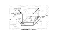
- FIG. 1 is a schematic configuration diagram of a laboratory animal biological information acquisition system 01 according to an embodiment of the present invention.
- the experimental animal biological information acquisition system 01 includes an electric power for the experimental animal biological information acquisition device 12, a transparent cage 14 in which the experimental animal biological information acquisition device 12 is embedded, and the experimental animal biological information acquisition device 12. Power transmission device 11 and a mounting table 15 in which the power transmission device 11 is incorporated and the transparent cage 14 is mounted.
- the experimental animal biological information acquisition system 01 further includes a server 13 that processes information transmitted from the power transmission device 11 in a wired or wireless manner, as shown in FIG.
- the server 13 records, calculates, processes, and displays information, and also controls the power transmission device.
- the power transmission device 11 controls the primary side coil (21 in FIG. 2) used for non-contact power transmission, an inverter circuit (not shown) that drives the primary side coil, and the experimental animal biological information acquisition device 12.
- a signal transmission / reception circuit (not shown) and a data reception circuit (not shown) for receiving data from the experimental animal biological information acquisition device 12 are included.
- the power transmission device 11 supplies power from the primary coil 21 to the experimental animal biological information acquisition device 12 having the secondary coil portion 22 by non-contact power transmission.
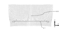
- FIG. 2 is an example of the magnetic field distribution 23 generated by the power transmission device 11 having the primary coil 21 according to the embodiment of the present invention.
- the primary coil 21 is a flat spiral coil or solenoid coil formed by a single wire or litz wire of a metal having electrical conductivity such as copper, aluminum, nickel, silver, gold, or an alloy thereof, or a printing method or an etching method. Etc., and a resonance circuit provided as necessary.
- the direction of the magnetic field generated by the power transmission device is the upward direction in the z direction, the forward direction in the x direction, and the right direction in the y direction.
- the generated magnetic field is a place in the breeding cage, the direction of the magnetic field changes, and for each place in the breeding cage 14, Become a specific orientation.
- most of the primary side coil and the like are oriented in the z direction, but depending on the position, the magnetic field is oriented in the x and y directions. Therefore, when the secondary coil unit 22 is a coil having a simple configuration such as a spiral coil or a solenoid coil similar to the primary coil, when the experimental animal biological information acquisition apparatus 12 is in an arbitrary position and orientation.
- the inductive coupling state between the primary side coil 21 and the secondary side coil part 22 changes greatly, and the amount of power transmission also changes greatly.
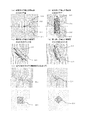
- FIG. 3 is a schematic diagram of the magnetic field distribution in the vicinity of the magnetic core 31 when the magnetic core 31 constituting the secondary coil portion 22 is near the center in FIG. 3A to 3D illustrate the case where the magnetic core 31 is cylindrical. It is understood that the magnetic field distribution varies greatly depending on the direction of the magnetic core 31 (in this embodiment, the direction of the experimental animal biological information acquisition device).
- FIG. 3A is a schematic diagram showing a magnetic field distribution in a cross section perpendicular to the axis 32 of the magnetic core 31 when the axis 32 of the magnetic core 31 is perpendicular to the magnetic field 23 by the primary coil 21. . It is understood that the magnetic field entering the magnetic core is opposite in the upper half 33 and the lower half 34 in the cross section.
- FIG. 3A is a schematic diagram showing a magnetic field distribution in a cross section perpendicular to the axis 32 of the magnetic core 31 when the axis 32 of the magnetic core 31 is perpendicular to the magnetic field 23 by the primary coil 21. . It is
- FIG. 3B is a schematic diagram showing a magnetic field distribution in the vicinity of the magnetic core 31 when the axis 32 of the magnetic core 31 is parallel to the magnetic field 23 generated by the primary coil 21. It is understood that the magnetic field entering the magnetic core 31 is opposite in the upper half 35 and the lower half 36 in the cross section.
- FIGS. 3C and 3D are schematic views showing the magnetic field distribution in the vicinity of the magnetic core 31 when the shaft 32 itself of the magnetic core 31 rotates in the vertical direction. It is understood that the direction of the magnetic field entering the magnetic core 31 gradually changes.
- FIG. 3E shows the magnetic field distribution when the cross-sectional shape of the magnetic core 31 is a triangle and a quadrangle when the arrangement angle is changed.
- the secondary coil portion 22 has a magnetic core 31 having a circular or polygonal cross-section perpendicular to the longitudinal direction, and a plurality of spiral coils 40a, 40b,.
- the plurality of spiral coils 40a, 40b,... are arranged side by side in the circumferential direction so as to be close to each other so as to cover the entire circumferential surface of the magnetic core 31. It is preferable that each coil of the spiral coil or the solenoid coil constituting the secondary side coil part is constituted not only by winding a conductor but also using a flexible coil.
- the flexible coil is a coil formed by forming a conductor in a thin film on a base material such as a flexible film by a printing method or an etching method. In that case, it is possible to form a plurality of coils on the same film or the like with less variation in characteristics and characteristics. Further, by laminating and connecting film-like coils formed on one side or both sides, the characteristic value can be adjusted and the coil can be easily bent. By aligning each laminated film coil with an adhesive or an adhesive, it is possible to prevent positional deviation of each laminated film coil.
- a system can be formed without adjustment due to the characteristics of the power receiving device.
- any power receiving device can be used without adjustment for any power transmission device.
- It can be easily attached to the power receiving circuit board, and can be bonded by thermocompression bonding using, for example, a solder paste, an anisotropic conductive film, or a metal-to-metal bond (Au gold-Au gold).
- Each circuit from the flexible coil and the power receiving circuit to the power consuming device can be constituted by an integrated flexible substrate, and the productivity is extremely high. Embodiments of the present invention will be described below in detail with reference to the drawings.
- FIG. 4A has a plurality of spirals formed by winding a magnetic core 31 having a circular cross-sectional shape perpendicular to the longitudinal direction and a conductor so that the outer shape is substantially square.
- the plurality of spiral coils 40a and 40b have their sides (40a1 and 40b1) and (40a2 and 40b2) close to each other so as to cover the entire peripheral surface of the magnetic core 31.
- the magnetic core 31 is arranged in an annular shape (to form a ring) in the circumferential direction.
- FIG. 4A shows an example using two spiral coils 40a and 40b.
- the spiral coils 40a and 40b are each formed to have a substantially square shape.
- the planar spiral coil formed so that the outer shape is formed in a substantially quadrangular shape by winding the winding is bent to form a shape along the outer peripheral surface of the magnetic core 31. Since the cross-sectional shape of the magnetic core 31 shown in FIG. 4 (a) is circular, the spiral coil is bent to have a curvature radius corresponding to the radius.
- the spiral coils 40a and 40b having a shape along the outer peripheral surface are arranged on the outer periphery of the magnetic core in such a manner that their sides are arranged close to each other and arranged in an annular shape.
- the one side 40a1 of the spiral coil 40a and the one side 40b1 of the spiral coil 40b are brought close to each other, and the other side 40a2 of the spiral coil 40a and the other side 40b2 of the spiral coil 40b are arranged adjacent to each other.
- the spiral coils 40a and 40b are viewed from the longitudinal direction of the magnetic core 31, they are arranged in a ring shape. In the present specification, this is called an annular coil array.
- the portion covering the magnetic core 31 contributes to the induced electromotive force, and the portion not covered does not contribute.
- a plurality of spiral coils are arranged so as to cover without a gap, and the induced electromotive force can be increased as compared with a case where a spiral coil having a circular outer shape is arranged.
- the polarity depends on the direction of winding the coil and the direction of the magnetic field, but both coils generate induced electromotive force.
- the state where power cannot be transmitted even if the two coils are rotated around the axis 32 of the magnetic core is only when the positions of the sides of the two coils are in the vertical direction. The occurrence of decline is suppressed.
- FIG. 3A the magnetic field distribution shown in FIG.
- FIG. 5A is a longitudinal sectional view in the longitudinal direction of the magnetic core 31 in FIG.
- FIG. 4B shows an example using three spiral coils 40a, 40b, and 40c.
- the spiral coils 40a, 40b, and 40c are each formed to have a substantially square shape.
- a planar spiral coil formed by winding a winding so as to form a substantially quadrangular shape is bent to form a shape along the outer peripheral surface of the magnetic core 31. Since the cross-sectional shape of the magnetic core 31 shown in FIG. 4B is circular, the spiral coil is given a curvature having a curvature radius corresponding to the radius.
- the spiral coils 40a, 40b, and 40c having a shape along the outer peripheral surface are arranged on the outer periphery of the magnetic core in such a manner that their respective sides are arranged close to each other in an annular shape.
- One side 40a1 of the spiral coil 40a is brought close to the one side 40b1 of the spiral coil 40b
- the other side 40b2 of the spiral coil 40b is brought close to the one side 40c1 of the spiral coil 40c
- the other side 40c2 of the spiral coil 40c is made to be close to the spiral coil 40a. Place it close to the other side.
- spiral coil 40a, 40b, 40c becomes a ring-shaped arrangement
- the polarity depends on the direction of winding the coil and the direction of the magnetic field, but all three coils generate induced electromotive force.
- the state in which power cannot be transmitted even if the three coils are rotated around the axis 32 of the magnetic core does not occur unless the positions of the three coils are symmetric to the left and right, thereby suppressing the occurrence of an extreme decrease in the amount of power supply. It is done.
- FIG. 5 is a schematic configuration diagram of the secondary coil portion 22 according to another embodiment.
- the structure of the coil of several various structures and the structure of various magnetic body cores 31 is illustrated.
- the magnetic core 31 has a circular cross-sectional shape, and the three spiral coils 40 a, 40 b, and 40 c extend along the peripheral surface of the magnetic core 31. It is curved.
- FIG. 5 (b) four spiral coils are used, and the spiral coils 40 a, 40 b, 40 c, and 40 d are also along the peripheral surface of the magnetic core 31.
- FIG. 3 (e) at least two or more coils generate induced electromotive force, so that a large decrease in the amount of power supply is eliminated.
- the magnetic core 31 in the upper half 35 and the lower half 36 in the cross section in the magnetic field distribution shown in FIG. 3B, the magnetic core 31 in the upper half 35 and the lower half 36 in the cross section. It is understood that the induced electromotive force cancels and is not output because the direction of the magnetic field entering is opposite. However, in the process of moving from the magnetic core shaft 32 itself to the magnetic field distribution shown in FIGS. 3 (a) to 3 (c) (d) and (b), the induced electromotive force is the number of magnetic bodies. It is understood that the magnetic field occurs until the angle formed by the direction of the magnetic field in the vicinity of the core and the axis 32 of the magnetic core becomes about 20 degrees.
- the secondary coil portion 22 is configured by arranging the two spiral coils 40 around the magnetic core 31 to form the secondary coil portion 22. Even if it rotates around 32, an extreme decrease in the amount of power supply can be suppressed. Therefore, when the experimental animal biological information acquiring apparatus 12 is configured, the magnetic core core 32 can be rotated around the axis 32, and the cross-sectional shape having a good biocompatibility can be obtained. Further, by arranging three or more spiral coils or solenoid coils 41 in an annular shape around the magnetic core to constitute the secondary coil portion 22, the secondary coil portion 22 is connected to the magnetic core shaft 32. Even if it rotates around, there is no significant decrease in the amount of power supply.
- the shape of the magnetic core 31 is not limited to the configuration illustrated in FIG.
- a cylindrical shape, a cylindrical shape, a triangular prism shape, a triangular cylindrical shape, a quadrangular prism shape, a quadrangular cylindrical shape, a polygonal cylindrical shape, a polygonal cylindrical shape, and the like are possible, but not limited thereto.
- the shape of a coil can be comprised planarly so that the outer surface of a core may be followed as illustrated in FIG.
- the magnetic core 31 can be formed into a cylindrical shape using a magnetic sheet that is formed into a columnar shape or a cylindrical shape by a method such as molding or cutting using a soft magnetic material typified by ferrite.
- the magnetic core 31 is made of a material having magnetic anisotropy, for example, flat magnetic fine particles, and a material having an easy magnetization axis oriented substantially perpendicular to the outer surface of the magnetic core, the magnetic field illustrated in FIG.
- the magnetic flux is nearly perpendicular to the outer surface of the magnetic core, and the interlinkage magnetic flux to the coil is increased
- the induced electromotive force can be generated more greatly.
- the demagnetizing field influences the end of the core to have a different magnetic field distribution from other locations.
- the position of the coil which comprises a secondary side coil part is needed.
- the performance is better when the coil outer shape is separated from the outer edge of the core material to the inside.
- the magnetic permeability is as small as 300 or less, the coil outer shape is The performance is better if it is configured to the end position. In terms of the interlinkage magnetic flux to the coil effective opening which is the source of the induced electromotive force, the performance is better when the magnetic permeability is increased.
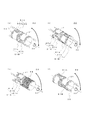
- FIG. 6A shows an embodiment in which the secondary coil portion 22 is configured using a plurality (two in this example) of annular coil arrays 51A and 51B on the peripheral surface of the magnetic core 31. Is illustrated.
- annular coil array 51A composed of two spiral coils 40a and 40b and an annular coil array 51B composed of two spiral coils 41a and 41b are used on the peripheral surface of the magnetic core 31.
- the secondary side coil part 22 is comprised.
- the spiral coils 40 a, 40 b, 41 a, 41 b shown in this example all have a substantially square shape and are curved so as to correspond to the outer peripheral surface of the magnetic core 31.
- the spiral coil 40a and the spiral coil 40b A ring-shaped annular coil array 51A is formed to cover half of the magnetic core 31.
- one side of the spiral coil 41a and one side of the spiral coil 41b are brought close to each other, and the other opposite side of the spiral coil 41a and the other opposite side of the spiral coil 41b are brought close to each other.
- a ring-shaped annular coil array 51B is formed with the coil 41b to cover the remaining half of the magnetic core 31.
- the terminals of the spiral coils 40a and 40b are provided on the left side in the drawing, and the terminals of the spiral coils 41a and 41b are provided on the right side in the drawing.
- the arrangement of the terminals may be determined as appropriate.
- an induced electromotive force is generated in any state, and the power supply amount does not significantly decrease with respect to the rotation of the magnetic core shaft 32 itself.
- an induced electromotive force is generated in the magnetic field of FIGS. 3A, 3C, and 3D.
- FIG. 6B shows an annular coil array 51 ⁇ / b> A composed of three spiral coils 40 a, 40 b and 40 c arranged on the peripheral surface of the magnetic core 31, and another three arranged on the peripheral surface of the magnetic core 31.
- An embodiment in which the secondary coil portion 22 is configured by two sets of annular coil arrays 51A and 51B of the annular coil array 51B configured by the spiral coils 41a, 41b, and 41c is illustrated.
- FIG. 6 (a) it is understood that this configuration has little reduction in the amount of power supply with respect to the rotation of the magnetic core shaft 32 itself. Considering the magnetic field distribution of FIG.
- the angle of the outer shape of each coil is estimated from the axis 32 of the magnetic core, and the configuration is made of three coils. Is formed by shifting the angles of the two annular coil arrays 51A and 51B by at least a quarter angle of about 120 degrees, that is, 30 degrees or more, and preferably by a half angle, that is, 60 degrees. When constituted by such two sets of coils, the fluctuation of the induced electromotive force can be minimized with respect to the rotation around the axis 32 of the magnetic core.
- the configuration of the coil is not limited to the configuration of three coils, and it is apparent from the description of the present invention that the same effect can be obtained if there are two sets of coils formed of three or more coils. is there.
- FIG. 6D Another embodiment of the present invention is illustrated in FIG.
- an annular coil array 51A composed of three spiral coils disposed on the peripheral surface of the magnetic core and a coil composed of a solenoid coil 56 having a magnetic core are disposed, and the secondary coil portion 22 is disposed.
- the spiral coil terminal 55 is disposed on the opposite side of 51A and 51B, but in the example shown in FIG. 6D, the spiral coil terminal 55 is both 51A and 51B. It is arranged on the right side in the drawing.
- the take-out direction may be determined as appropriate in consideration of assembly productivity.
- the secondary coil portion 22 is configured by two sets of annular coil arrays composed of a plurality of coils arranged on the peripheral surface of the magnetic core 31, so that the axis of the magnetic core
- the amount of power supply can be reduced with respect to the rotation of the magnetic core shaft 32 itself. Therefore, when the experimental animal biological information acquisition device 12 is configured, the magnetic core can be rotated around the axis 32 of the magnetic core, and can have a round cross-sectional shape with good biocompatibility.
- the shaft 32 itself can be rotated, and power can be supplied regardless of the position and posture.
- the secondary side coil portion is made up of a coil composed of a set of three or more coils arranged on the peripheral surface of the magnetic core and a solenoid coil having the magnetic core.
- the magnetic core can be rotated around the axis 32 of the magnetic core, and can have a round cross-sectional shape with good biocompatibility.
- the shaft 32 itself can be rotated, and power can be supplied regardless of the position and posture.
- the magnetic core 31 may be integrated, but the coil configured in the magnetic core configured separately can be configured to be magnetically strongly coupled using a magnetic adhesive or the like. . The convenience of manufacturing such as strongly coupling an integrated magnetic core or separate magnetic cores is increased.
- FIG. 7 is a schematic circuit block configuration diagram of the experimental animal biological information acquisition device 12, the power transmission device 11, and the experimental animal biological information acquisition system 01.
- the experimental animal biological information acquisition device 12 includes a power reception circuit 61 having a secondary coil portion 22 constituting a power reception device, a circuit block of an addition circuit 62, a power supply circuit 63, and each circuit block of a power consumption device 64. Embodiments of each circuit block will be described below.
- the power receiving circuit 61 includes the secondary coil unit 22 and includes a parallel, series, or series-parallel resonant circuit as necessary.
- the adding circuit 62 adds the output of the power receiving circuit 61 to the induced electromotive force of a plurality of coils constituting the secondary side coil unit 22, and supplies the necessary power to the power consuming device 64 via the power supply circuit 63. Supply.
- a circuit in which a capacitance 72 is connected in parallel to a rectifier circuit 71, and a circuit in which a parallel connection, a series connection, or a series-parallel connection are connected are illustrated in FIGS. .
- the rectifier circuit 71 can be a half-end rectifier circuit or a full-wave rectifier circuit.
- the capacitance 72 is about 0.1 to 100 ⁇ F, and preferably 1 to 10 ⁇ F.
- connection configuration depends on the characteristics of the power supply circuit 63 and the power consuming device 64 connected to the adder circuit 62, but when the power supply circuit 63 and the subsequent loads are taken as loads, if the load is heavy at 1 k ⁇ or less, it is connected in parallel.
- the load is lighter than 10 k ⁇ , series connection is suitable, and when the load is in the middle, series-parallel connection is suitable.
- the load is 100 to 1000 ⁇ , and a parallel connection type adder circuit 62 is suitable.
- the limit circuit 65 is configured in the final stage of the adder circuit 62. As shown in an example of implementation in FIGS.
- the limiting circuit 65 is used, for example, as a power supply circuit by using a Zener diode and a transistor, or by using a Zener diode. By doing in this way, the received electric power from the secondary side coil part 22 of this invention can be used effectively.
- the power supply circuit 63 is a circuit block that supplies power suitable for the power consuming device 64.
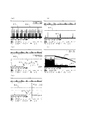
- FIG. 9 illustrates the voltage and current at the input unit of the power consuming device 64.
- the power consuming device 64 often consumes power intermittently with the recent progress of digitization.
- FIG. 9A is a 10-second diagram illustrating the current 81 and the voltage 82 in the power consuming device 64.
- the current 81 of about 20 mA is consumed intermittently at intervals of about 2 seconds at intervals of about 2 seconds (details are shown in FIG. 9 (c)), and otherwise about 0.7 milliseconds at intervals of about 80 milliseconds. (The details are shown in FIGS.
- the power supply 67 related to the intermittent power consumption and the power supply related to the time-average power consumption 66 are separately configured. With this configuration, the power supplied from the power reception circuit 61 and the addition circuit 62 to the power supply circuit 63 does not need to correspond to intermittent power consumption, and may correspond to time-average power consumption. . Therefore, the configuration of the power reception circuit 61, the addition circuit 62, and the power supply circuit 63 can be simplified and reduced.
- the power supply circuit 63 can be realized using, for example, a low-loss linear regulator or a DC-DC converter.
- a power supply 67 related to intermittent power consumption is supplied with a capacitor having a small equivalent series resistance, for example, a multilayer ceramic capacitor.
- the equivalent series resistance is preferably 20 m ⁇ or less. If the power peak of intermittent power consumption is, for example, 10 to 50 mW, a capacitor of 20 to 100 ⁇ F is suitable.
- the power supply 66 related to time-average power consumption is supplied with a capacitor having a large capacitance. For example, an electric double layer capacitor having a small equivalent series resistance is suitable. If the time average power consumption is about 3 mW, for example, it is desirable that the equivalent series resistance is 50 ⁇ or less and the capacitance is 2 to 10 mF.
- 9D illustrates changes in voltage and current at the input unit of the power consuming device when power supply to the power consuming device is stopped.
- the power supply to the power supply device 63 is interrupted, an instantaneous voltage drop may occur during intermittent power supply, resulting in a malfunction in the operation of the power consumption device.
- the equivalent series resistance of the electric double layer capacitor is 50 ⁇ or less.
- the power supply 67 related to intermittent power consumption due to the power consumption of the power consuming device 64 can be understood that a decrease in electrical energy can be compensated from the power supply 66 related to time-average power consumption, continuous power supply can be realized, and operation without stopping can be realized.
- the power consuming device 64 includes one or more sensors for acquiring biological information of a laboratory animal, such as a temperature sensor, an acceleration sensor, a pulsation sensor (such as a heart rate sensor or a pulse sensor), a pressure sensor, and bioelectricity. It includes at least a sensor, a measurement / calculation / processing circuit for biological information, a control circuit, a communication circuit for the biological information and control signals, and a communication antenna.
- the communication circuit is implemented by, for example, Bluetooth (registered trademark) with low power consumption.
- FIG. 10 illustrates an embodiment of a capsule configuration.
- a configuration may be adopted in which the secondary coil portion 22 is configured around the cylindrical magnetic core 31, and various circuits are disposed inside the cylindrical core.
- the secondary coil portion 22 is formed around the columnar magnetic core 31, and various circuits and the like for configuring the experimental animal biological information acquiring device 12 are provided around the secondary coil portion 22.
- the capsule 90 can be made of a biocompatible material such as glass, ceramics, biocompatible plastic, and the like.
- the capsule 90 When the capsule is made of glass or ceramics, the capsule 90 is divided into two or more, and after enclosing the secondary coil section and various circuits, it is adhered by biocompatible epoxy or the like. Can be configured. When the capsule 90 is made of biocompatible plastic, it is divided into two or more in the same manner, and the secondary coil portion 22 and various circuits are encapsulated, and then adhered and adhered with biocompatible epoxy or the like.
- the capsule 90 can be configured by a method such as bonding by ultrasonic fusion.
- a dome shape or the like is provided at least at one end of the cylindrical core.
- the capsule 90 may be formed by coating the whole with a liquid biocompatible plastic by a method such as dipping or spraying and then curing by a method such as dry curing, heat curing, ultraviolet curing, or electron beam curing. it can.
- the method of coating using the liquid biocompatible plastic is effective even when used for joining the capsule 90 divided in two. In that case, the material of the capsule 90 need not be biocompatible. With such a configuration, it is possible to obtain the experimental animal biological information acquisition apparatus 12 that is not affected by the body fluid of the experimental animal, does not adversely affect the experimental animal, and can have a round cross-sectional shape with high biocompatibility.
- FIG. 1 shows an outline of the overall configuration of the experimental animal biological information acquisition system.
- the power transmission device 11 having the primary side coil 21 is located below the rearing cage 14 in which the experimental animal embedded with the experimental animal biological information acquiring device 12 having the secondary side coil portion 22 is bred, and the power transmission device.
- the upper surface is substantially flat and constitutes a mounting table 15 for the breeding cage.
- the power transmission device 11 has a receiving device for data transmitted by the experimental animal biological information acquiring device 12, and further has a device for transmitting and receiving control signals.
- Direction of the magnetic field at the location of the secondary coil portion 22 by the primary side coil 21 Vertical direction Strength of the magnetic field at the location of the secondary side coil portion 22 by the primary side coil 21 100 ⁇ T AC drive frequency of primary coil 21 500 kHz
- the shape of the secondary side coil part 22 The coil which curved in the shape which followed the outer surface of a cross-section round core
- the load impedance seen from the addition circuit of the secondary side coil part 22 500 ⁇ Coil wire ⁇ 0.06-0.08mm Number of windings 30-50
- a cylindrical addition circuit having an outer shape of a magnetic core: ⁇ 5 mm ⁇ length 10 mm and thickness: 0.2 mm is an example of parallel connection.
- Characteristic example-1 The secondary coil is composed of two coils and two sets Load end voltage (V) Power (mW) Magnetic core axis perpendicular to magnetic field direction 3.2 19 Parallel 2 8 45 degrees 2.4 12
- Characteristic example-2 Secondary coil part is composed of 3 coils and 2 sets Load terminal voltage (V) Power (mW) Magnetic material core axis is perpendicular to magnetic field direction 3 17 Parallel 1.8 5.5 45 degrees 2.2 9
- the experimental animal living body information acquisition apparatus 12 of the present invention has an intermittent power consumption of about 50 mW at the peak and about 25 mW on the average of the intermittent consumption time. The overall average power consumption is about 3 mW. Therefore, according to the present invention, non-contact power transmission to the implantable experimental animal living body information acquiring apparatus 12 is possible, and the implantable experimental animal living body information acquiring apparatus 12 and the implantable experimental animal living body information acquiring system 01 can be realized.
- the power receiving device of the present invention power can be stably supplied regardless of the arrangement and orientation of the primary side coil and the secondary side coil part by the invention of the secondary side coil part and the circuit configuration. It can be omnidirectional.
- the use of the power receiving device of the present invention for the experimental animal biological information acquisition device eliminates the need for a power line for driving the biological information acquisition device, and does not limit the operation of the experimental animal as in the wired system.
- it can be made into a biocompatible shape that does not give stress to experimental animals, is small and lightweight, can acquire biological information in real time, and continuously biometric information without interruption, regardless of the posture and position of multiple moving small animals It can be acquired and can contribute to the development of drug development.
- the non-directional non-contact power feeding technology realized in the present invention is expected to be applied not only to experimental animal biological information acquisition devices but also to a wide range of devices where the position of the power receiving device is indefinite, contributing to industrial development. Can do.
Landscapes
- Engineering & Computer Science (AREA)
- Power Engineering (AREA)
- Life Sciences & Earth Sciences (AREA)
- Environmental Sciences (AREA)
- Computer Networks & Wireless Communication (AREA)
- Animal Husbandry (AREA)
- Biodiversity & Conservation Biology (AREA)
- Endoscopes (AREA)
- Magnetic Treatment Devices (AREA)
Abstract
飼育ケージ14内の複数匹の実験動物に埋め込まれた実験動物生体情報取得装置12に非接触で電力伝送する技術であり、飼育ケージ14を送電側が覆うことが無く外部から実験動物の行動を観察でき、実験動物の向きや位置によらず継続的に給電できる受電装置を提供すること。 2次側コイル部22は、長手方向に垂直な断面形状が円形の磁性体コア31と、外形が略四角形となるように導体を巻回して構成された複数のスパイラルコイル40a、40bを有し、複数のスパイラルコイル40a、40bは、それぞれその辺同士(40a1と40b1)、(40a2と40b2)を近接させて、磁性体コア31の周面全体を覆うようにして、磁性体コア31の周方向に環状に(リングを形成するように)配置されている。
Description
本発明は、受電装置、実験動物生体情報取得装置及び実験動物生体情報取得システムに関する。
医薬品開発等では、その効果を評価するために、飼育ケージ内で飼育されている多数のマウスなどの小動物を使った実験が日常的に実施されている。実験を実施する際、小動物には体温や活動量、心拍、血圧等の生体情報を経時的に取得する為の生体情報取得装置が装着される。生体情報取得装置は、小動物に外付けする方法と生体に埋め込む方法がとられているが、より正確な値を知るために、埋め込む方法が多くなっている。
埋め込む方法での重要なポイントは、生体情報取得装置への電力供給である。有線方式では小動物の動作が制限されるため、有線方式によらない何らかの電力供給方式が必要とされる。
埋め込む方法での重要なポイントは、生体情報取得装置への電力供給である。有線方式では小動物の動作が制限されるため、有線方式によらない何らかの電力供給方式が必要とされる。
生体情報を取得するに際しては、多数の実験動物を用いて、長期間にわたり、用途によっては計測間隔をあけずに(例えば数秒間隔)、多くの生体情報を取得することが望まれる。また、信頼性のある実験データを得るためには、実験動物にストレスを与えないようにする必要がある。そのためには、生体情報取得装置の形状は生体親和性のある形状であり、生体情報取得装置の寸法重量は小型軽量(一般的に実験動物の体重の1/10以下といわれる)であることが望まれる。
さらに、その生体情報をリアルタイムに取得したい、その際の動作や姿勢等の観察を同時に行いたいというニーズがある。実験動物は飼育ケージ内に放たれ、自由に立ち上がったり歩き回ったりするので、どこに、どんな姿勢で実験動物がいようと、途切れることなく、生体情報を継続的に取得でき、実験動物を観察ができることが望まれる。
また、実験動物を多量に使用するため、一つの生体情報取得装置の消費電力(発熱)が少なく、出来るだけ安価であることが望まれる。
さらに、その生体情報をリアルタイムに取得したい、その際の動作や姿勢等の観察を同時に行いたいというニーズがある。実験動物は飼育ケージ内に放たれ、自由に立ち上がったり歩き回ったりするので、どこに、どんな姿勢で実験動物がいようと、途切れることなく、生体情報を継続的に取得でき、実験動物を観察ができることが望まれる。
また、実験動物を多量に使用するため、一つの生体情報取得装置の消費電力(発熱)が少なく、出来るだけ安価であることが望まれる。
従来の埋め込み型の実験動物生体情報取得装置のうちの有線方式によらない電力供給方式によるものとして、例えば非特許文献1で開示される製品がある。この製品は一次電池を内蔵しており、一つの飼育ケージで複数の実験動物の生体情報の取得ができる。
他の有線によらない電力供給方式による従来の実験動物生体情報取得装置として、例えば非特許文献2で開示される製品がある。この製品は、非接触電力伝送技術を用いて受電側に給電しているので、生体情報をリアルタイムに長期間にわたって取得して送信することができる。
しかし、非接触電力伝送技術を用いる場合、実験動物の姿勢や位置により電磁誘導結合が変化して給電を行うことが出来なくなることがある。この課題の解決に関する先行技術として、例えば特許文献1がある。
特許文献1には、植え込み型医療器具システムにおける非接触電力伝送技術が開示されており、1次側コイルにおいて2軸直交のデュアルコイルを用いた90度位相外れ駆動による回転磁界の生成により送受電間の結合による給電量の極端な低下の抑制を行うことが開示されている。
特許文献1には、植え込み型医療器具システムにおける非接触電力伝送技術が開示されており、1次側コイルにおいて2軸直交のデュアルコイルを用いた90度位相外れ駆動による回転磁界の生成により送受電間の結合による給電量の極端な低下の抑制を行うことが開示されている。
特許文献2には、体内滞留型医療機器が体内でどのような向きであってもその機器に非接触にて効率的にエネルギーを供給できるように、それぞれ異なる方向に磁界を発生するように設置される複数の1次側コイル(ヘルムホルツ型コイル)が開示されている。
特許文献3には、送電コイルと受電コイルの位置関係によらず高効率での電力伝送を実現するために、1次側コイルと2次側コイルの少なくとも一方を、球形状に組みつけられた複数のヘリカルコイルから構成することで、1次側と2次側コイル間の位置ズレの影響を軽減できることが開示されている。
DATA SCIENCES INTERNATIONAL 社ホームページ
MILLAR社ホームページ User Manual for Millar Mouse Telemetry Systems
非特許文献1に記載の先行技術では、小型実験動物に埋め込むため、小型にしてかつ軽量にする必要があり、電池容量が小さい。そのためデータ取得頻度を高くすることやデータ量を多くすることが困難、データ通信間隔を短くすることが困難、リアルタイムに送信しようとすると長期間の動作が出来ない、という課題がある。また、1次電池を内蔵するために、装置の形状が制限され生体親和性のある形状、特に丸型形状とするのが困難であるという課題がある。
非特許文献2に記載の先行技術では、飼育用ケージあたり1~2匹の実験動物の生体情報の取得しか出来ない。そのため多数の送電装置が必要となり、コストや消費電力(発熱)で課題がある。受電側の重量が重いため(2.5g)小型マウスのような軽量な小動物の実験に用いることが出来ない、という課題がある。更に、本製品のユーザーズマニュアル(User Manual for Millar Mouse Telemetry Systems)によれば飼育ケージ内の高いところ、具体的にはケージの底面から高さ約70mmでは実験動物の姿勢等により給電出来なくなりデータ送受信ができなくなるという課題がある。
特許文献1に開示された先行技術では、送信側の駆動回路が複数必要であるため、送電電力が2倍必要、よって発熱も多い、送電側のコストが高い、2軸による回転磁場では、任意の姿勢に対する効果が不十分という課題がある。
特許文献2に開示された先行技術では、送電側の駆動回路が複数必要であるため、送電電力が3倍、よって発熱もより多い、送電側のコストが高い、また観察対象である受電側を囲み覆ってしまうため、実験動物を観察することが困難という課題がある。
特許文献3に開示された先行技術では、送受電ヘリカルコイルペアを常時監視調整する必要があり、送受電ともに複雑かつ高コストとなる、という課題がある。また、受電側にヘリカルコイルを用いると、受電側の体積が大きくなり小型軽量化が困難になる、という課題がある。
本発明は上述した点に鑑みてなされたものであり、送電側は構成の簡単なスパイラルコイルまたはソレノイドコイルなどで1次側コイルを構成できる。受電側は簡単な構成で、作りやすく安価であり、一つの飼育ケージ内の複数匹の実験動物への埋め込みに際して、生体親和性の高い丸型断面形状に適した受電装置の回転による給電量の低下が発生しない、すなわち実験動物の向きや位置によらず継続的に給電でき、飼育ケージを送電側が覆うことが無く外部から実験動物の行動を観察可能である、受電装置、埋め込み型実験動物生体情報取得装置および実験動物生体情報取得システムを提供することを課題とする。
請求項1に係る発明は、送電装置の1次側コイル部から非接触で伝送された電力を受電する2次側コイル部を有する受電装置であり、
前記2次側コイル部は、長手方向に垂直な断面形状が円形又は多角形の磁性体コアと、導体を巻回して構成された複数のスパイラルコイルを有し、
前記複数のスパイラルコイルは、相互に近接させて、前記磁性体コアの周面全体を覆うにして、周方向に環状に配置されていることを特徴とする受電装置である。環状に配置された前記複数のスパイラルコイルを以下「環状コイル列」という。
ここで、スパイラルコイルとは、導線を渦巻き状に巻いた平面状のコイルである。整列巻のようにスパイラルコイルを積層したコイルもスパイラルコイルに含まれる。後述のソレノイドコイルとは、導線を疎又は密にらせん状に巻いたコイルであり、筒状で細長い形状を有するコイルである。巻回数も要求特性に応じて適宜設定される。
請求項2に係る発明は、送電装置の1次側コイル部から非接触で伝送された電力を受電する2次側コイル部を有する受電装置であり、
前記2次側コイル部は、長手方向に垂直な断面形状が円形又は多角形の磁性体コアと、外形が略四角形となるように導体を巻回して構成された複数のスパイラルコイルを有し、
前記複数のスパイラルコイルは、それぞれその辺同士を近接させて、前記磁性体コアの周面全体を覆うようにして、前記磁性体コアの周方向に環状に配置されていることを特徴とする受電装置である。
請求項3に係る発明は、前記複数のスパイラルコイルは2個、3個、又は4個以上である請求項1又は2記載の受電装置である。
請求項4に係る発明は、前記環状コイル列が、前記磁性体コアの軸方向に、複数設けられている請求項1ないし3のいずれか1項記載の受電装置である。
請求項5に係る発明は、前記環状コイル列における前記辺と、前記他の環状コイル列における前記辺とは、長手方向垂直面からみて周方向にずれていることを特徴とする請求項4記載の受電装置である。
請求項6に係る発明は、前記環状コイル列を構成する複数のスパイラルコイルの数は、他の環状コイル列を構成する複数のスパイラルコイルの数と異なることを特徴とする請求項4又は5記載の受電装置である。
請求項7に係る発明は、前記環状コイル列を構成する複数のスパイラルコイルの数は、他の環状コイル列を構成する複数のスパイラルコイルの数と同じであることを特徴とする請求項4又は5記載の受電装置である。
請求項8に係る発明は、前記環状コイル列の軸方向外側に、ソレノイドコイルが設けられている請求項1ないし3のいずれか1項記載の受電装置である。
請求項9に係る発明は、前記磁性体コアの表面形状に沿うように前記スパイラルコイルをその一部又は全体を撓ませて配置したことを特徴する請求項1ないし8のいずれか1項記載の受電装置である。
請求項10に係る発明は、前記磁性体コアは多角形であり、前記辺は、前記多角形の頂点に位置する請求項1ないし9のいずれか1項記載の受電装置である。
請求項11に係る発明は、前記磁性体コアは多角形であり、前記辺は、前記多角形の頂点以外の位置に位置する請求項1ないし9のいずれか1項記載の受電装置である。
請求項12に係る発明は、前記磁性体コアは多角形であり、前記スパイラルコイルは、前記多角形の角数より少ない数配置されている請求項1ないし9のいずれか1項記載の受電装置である。
請求項13に係る発明は、前記磁性体コアは円形であり、前記環状コイル列1個を構成する前記スパイラルコイルは2ないし4個である請求項1ないし9のいずれか1項記載の受電装置である。
請求項14に係る発明は、請求項1ないし13のいずれか1項記載のスパイラルコイル又は請求項8ないし13のいずれか1項記載のソレノイドコイルに生じる誘導起電力を受ける受電回路と、前記受電回路の出力を並列加算、直列加算もしくは直並列加算する加算回路と、電力を電力消費装置に供給する電力供給回路を有する受電装置である。
請求項15に係る発明は、請求項1ないし14のいずれか1項記載のスパイラルコイル又は請求項8ないし14のいずれか1項記載のソレノイドコイルは、フレキシブルコイルである受電装置である。
請求項16に係る発明は、前記電力消費装置は、間歇的に電力消費がなされる回路である請求項14又は15記載の受電装置である。
請求項17に係る発明は、前記電力供給回路は、少なくとも、間歇的な電力消費に係わる給電回路と時間平均的な電力消費に係わる給電回路の2つの回路を含むことを特徴とする請求項14ないし16のいずれか1項記載の受電装置である。
請求項18に係る発明は、前記間歇的な電力消費に係わる給電回路には、セラミックコンデンサが含まれ、前記時間平均的な電力消費に係わる給電回路には、電気二重層コンデンサが含まれることを特徴とする請求項17記載の受電装置である。
請求項19に係る発明は、磁性体コアは、磁化容易軸を磁性体コア外面にほぼ垂直に配向させた材料からなることを特徴とする請求項1ないし18のいずれか1項記載の受電装置である。
請求項20に係る発明は、請求項1ないし19のいずれか1項記載の受電装置と電力消費装置とを含み、実験動物内に埋め込まれる実験動物生体情報取得装置である。
請求項21に係る発明は、前記電力消費装置は、実験動物の生体情報を取得する1つ以上のセンサ、前記生体情報の演算・処理回路と制御回路、および前記生体情報と制御信号の送受信回路であることを特徴とする請求項20記載の実験動物生体情報取得装置である。
請求項22に係る発明は、前記受電装置、前記電力消費装置は、カプセルに内蔵されていることを特徴とする請求項20又は21記載の実験動物生体情報取得装置である。
請求項23に係る発明は、請求項20ないし22のいずれか1項記載の実験動物生体情報取得装置が埋め込まれた実験動物が収納される透明ケージと、前記実験動物生体情報取得装置に電力を伝送する送電装置と、前記送電装置を内蔵し前記透明ケージを載置する載置台と、送信された情報を処理、記録するとともに送電装置を制御するサーバーと、を有する実験動物生体情報取得システムである。
本発明によれば、磁性体コアの軸の周りの回転に関して、給電量の大きな低下の発生がおさえられる。それゆえ、実験動物生体情報取得装置を生体親和性の良い断面丸型形状とできる効果がある。
スパイラルコイルを略四角形とし、辺同士を隣接させて配置した場合には、隙間なく配置が行われ、誘導起電力誘起が効果的に行われる。その結果、より効果的に受電を行うことが可能となる。
磁性体コアの軸方向に、環状コイル列を複数設けることにより、磁性体コアの軸周りの回転、および磁性体コア軸の立ち上がり変動に関して、給電量の大きな低下の発生がより一層少なくなり無くなり、位置や姿勢に関係なく給電できる効果がある。
01 実験動物生体情報取得システム
11 送電装置
12 実験動物生体情報取得装置
13 サーバー
14 飼育ケージ
15 載置台
21 1次側コイル
22 2次側コイル部
23 1次側コイルの発生する磁場
31 2次側コイル部を構成する磁性体コア
32 磁性体コアの軸
33 磁性体コアの断面の上半分
34 磁性体コアの断面の下半分
35 磁性体コアの断面の上半分
36 磁性体コアの断面の下半分
40a、40b、40c、40d 2次側コイル部を構成するスパイラルコイル
40a1、40a2、40b1、40b2、40c1、40c2 スパイラルコイルの辺
41a、41b、41c 2次側コイル部を構成するスパイラルコイル
51A、51B 環状コイル列
55 コイル端子
56 2次側コイル部のソレノイドコイル
61 2次側コイル部を有する受電回路
62 加算回路
63 電力供給回路
以下、本発明の実施の形態を図に基づいて説明する。
図1は、本発明の実施の一形態に係わる実験動物生体情報取得システム01の概略構成図である。この実験動物生体情報取得システム01は、実験動物生体情報取得装置12と、実験動物生体情報取得装置12が埋め込まれた実験動物が収納される透明ケージ14と、実験動物生体情報取得装置12に電力を伝送する送電装置11と、送電装置11を内蔵し、透明ケージ14を載置する載置台15とを有する。
この実験動物生体情報取得システム01は、さらに図7に示すように送電装置11から有線方式または無線方式で送信される情報を処理するサーバー13を有している。サーバー13は、情報を記録、演算、処理、表示するとともに、送電装置の制御も行う。
送電装置11は、非接触電力伝送に用いる1次側コイル(図2の21)と、1次側コイルを駆動するインバータ回路(図示せず)と、実験動物生体情報取得装置12を制御する制御信号の送受信回路(図示せず)と、実験動物生体情報取得装置12からのデータの受信を行うデータ受信回路(図示せず)を有する。送電装置11は、非接触電力伝送にて1次側コイル21から2次側コイル部22を有する実験動物生体情報取得装置12に電力を供給する。
図2は、本発明の実施の一形態に係り、1次側コイル21を有する送電装置11が発生する磁場分布23の一例である。
1次側コイル21は、銅、アルミニウム、ニッケル、銀、金などの電気導電性のある金属及びその合金の単線やリッツ線もしくは印刷法やエッチング法で形成された平面状のスパイラルコイルやソレノイドコイル等のコイルと、必要に応じて設けられる共振回路で構成されている。
送電装置の発生する磁場の向きを、z方向を上方向、x方向を手前方向、y方向を右方向とする。1次側コイル21が前記のような公知の簡単なコイルで構成されていると、その発生する磁場は飼育ケージ内の場所で、磁場の向きが変化し、飼育ケージ14内の場所毎に、特定の向きとなる。図2の実施の一形態では、1次側コイルの中央部など大部分がz方向を向いているが、位置によっては、x方向やy方向の磁場の向きとなる。その為、2次側コイル部22も1次側コイルと同様のスパイラルコイルやソレノイドコイル等の簡単な構成のコイルであると、実験動物生体情報取得装置12が任意の位置や向きであるときに、1次側コイル21と2次側コイル部22との誘導結合状態が大きく変化し、電力伝送量も大きく変化する。
図3は、図2における中央付近に2次側コイル部22を構成する磁性体コア31がある場合の磁性体コア31近傍の磁界分布の概略図である。
図3(a)~(d)では磁性体コア31が円筒型の場合を例示する。磁性体コア31の向き(本形態においては実験動物生体情報取得装置の向き)により磁界分布が大きく変わることが理解される。
図3(a)は、磁性体コア31の軸32が1次側コイル21による磁場23と垂直にあるときの磁性体コア31の軸32に垂直な断面での磁界分布を示す概略図である。断面の上半分33と下半分34で磁性体コアに入り込む磁界の向きが反対となることが理解される。
図3(b)は、磁性体コア31の軸32が1次側コイル21による磁場23と平行を向いている場合の磁性体コア31近傍磁界分布を示す概略図である。断面の上半分35と下半分36で磁性体コア31に入り込む磁界の向きが反対となることが理解される。
図3(c)、(d)は、磁性体コア31の軸32そのものが上下方向へ回転する場合の磁性体コア31近傍の磁界分布を示す概略図である。磁性体コア31に入り込む磁界の向きが徐々に変化することが理解される。
図3(e)は、磁性体コア31の断面形状が三角形の場合と四角形の場合における磁界分布を、配置角度を変えた場合とともに示している。
図4~図6に本発明の実施の形態に係る受電装置の2次側コイル部の例を示す。
2次側コイル部22は、長手方向に垂直な断面形状が円形又は多角形の磁性体コア31と、導体を巻回して構成された複数のスパイラルコイル40a、40b、・、・を有し、複数のスパイラルコイル40a、40b、・、・は、相互に近接させて、前記磁性体コア31の周面全体を覆うにして、周方向に並べて配置されている。
2次側コイル部を構成するスパイラルコイルあるいはソレノイドコイルの各コイルは、導体を巻回して構成することだけではなくフレキシブルコイルを用いて構成することが好ましい。フレキシブルコイルは、可とう性のあるフィルム等の下地材の上に、印刷法やエッチング法で導体を薄膜状に形成してコイルとしたものである。その場合には複数のコイルを同一のフィルム等に配置や特性のバラツキを少なく形成できる。また片面もしくは両面に形成したフィルム状のコイルを積層し接続することで、特性値の調整が可能となるとともに、コイルを撓ませることが容易に出来る。各積層フィルムコイルは接着剤や粘着剤で合わせる事で、各積層フィルムコイルの位置ズレを防ぐことが出来る。
フレキシブルコイルを、受電装置もしくは生体情報取得装置・システムに使用した場合、受電装置・生体情報取得装置においては、特性の調整が容易、特性再現性良好、生産性良好、撓ませるのが容易となり、性能バラツキが無くなる。より詳細に述べる。
(1)環状コイル列を構成する各々のスパイラルコイルの特性を制御(そろえる)必要があるが、巻回コイルでは特性の制御(そろえる)が困難である。フレキシブルコイルであれば特性を揃えることが容易であり、また、コイル毎に異なる特性に制御することが容易である。また、品質バラツキなく生産性がよい。
(2)巻回コイルでは、コイルを撓ませる際にバラツキが生じやすいが、フレキシブルコイルであれば撓ませることが容易であり、バラツキが生じない。
(3)例えば4層フレキシブルコイルでは撓ませることが困難なので両面フレキシブルコイル2枚もしくは両面フレキシブルコイルと片面フレキシブルコイル各1枚接着材、粘着剤で貼りあわせれば撓ませるのが容易で撓ませたときの特性バラツキを抑えられる
(4)受電回路基板への取り付けが容易であり、例えばハンダペースト、異方性導電フィルムや(Au金-Au金の)金属間結合等を利用して熱圧着等で接合できる。
(5)フレキシブルコイル及び受電回路から電力消費装置までの各回路を一体のフレキシブル基板で構成でき、生産性が極めて高い
生体情報取得システムについては、次のような利点がある。
(1)複数の送電装置に任意の受電装置を組み合わせる際に、上記受電装置の特徴から調整無しでシステム化できる。すなわち、いずれの受電装置もいずれの送伝装置に無調整で使用できる。
(2)受電回路基板への取り付けが容易であり、例えばハンダペースト、異方性導電フィルムや(Au金-Au金の)金属間結合等を利用して熱圧着等で接合できる。
(3)フレキシブルコイル及び受電回路から電力消費装置までの各回路を一体のフレキシブル基板で構成でき、生産性が極めて高い。
以下に本発明の実施の形態を図面に基づきより詳細に説明する。
図4(a)に示す2次側コイル部22は、長手方向に垂直な断面形状が円形の磁性体コア31と、外形が略四角形となるように導体を巻回して構成された複数のスパイラルコイル40a、40bを有し、複数のスパイラルコイル40a、40bは、それぞれその辺同士(40a1と40b1)、(40a2と40b2)を近接させて、磁性体コア31の周面全体を覆うようにして、磁性体コア31の周方向に環状に(リングを形成するように)配置されている。
図4(a)は、2個のスパイラルコイル40a、40bを用いた例を示している。
スパイラルコイル40a、40bはそれぞれ略四角形状をなすように形成されている。巻線を巻回して外形が略四角形状をなすように形成された平面状のスパイラルコイルに、撓みを与えて、磁性体コア31の外周面に沿った形状とする。図4(a)に示す磁性体コア31の断面形状は円形であるためその半径に対応した曲率半径となる撓みをスパイラルコイルに与える。外周面に沿った形状とされたスパイラルコイル40a、40bは、それぞれの辺同士を近接させて環状に並べて磁性体コアの外周に配置されている。スパイラルコイル40aの一辺40a1とスパイラルコイル40bの一辺40b1と近接させるとともに、スパイラルコイル40aの他の一辺40a2とスパイラルコイル40bの他の一辺40b2とを隣接配置する。これにより、スパイラルコイル40a、40bは磁性体コア31の長手方向から見た場合、リング状配列となる。本明細書においてはこれを環状コイル列と称する。
磁性体コア31を覆っている部分が誘導起電力に寄与し、覆わない部分は寄与しない。隙間無く覆うように複数のスパイラルコイルを配置することになり、外形が円状のスパイラルコイルを配置した場合に比べて誘導起電力を大きくすることが可能となる。
本構成で図3(a)の磁界分布を考えると、極性はコイルを巻く向きと磁場の向きに依存するが2つのコイルは共に誘導起電力を生じる。2つのコイルを磁性体コアの軸32の周りに回転しても電力伝送出来ない状態は、2つのコイルの各々の辺の位置が上下方向になった場合のみであるため、給電量の極端な低下の発生が抑えられる。
図3(b)に示す磁界分布を考えると、断面の上半分35と下半分36で磁性体コア31に入り込む磁界の向きが反対となるため誘導起電力が相殺して出力されないことが理解される。しかし、本構成では、磁性体コア31の軸32そのものの回転により図3(a)から(c)を経て(d)、さらに(b)に示す磁界分布に移っていく過程において、誘導起電力は、磁性体コア31近傍の磁界の向きと磁性体コア31の軸32のなす角度が20度程度になるまでは発生することが理解される。
スパイラルコイルを3つ用いて環状コイル列を形成した例を図4(b)、図5(a)に基づいて説明する。なお、図5(a)は、図4(b)における磁性体コア31の長手方向垂直断面図である。
図4(b)は、3個のスパイラルコイル40a、40b、40cを用いた例を示してい
る。
スパイラルコイル40a、40b、40cはそれぞれ略四角形状をなすように形成されている。
略四角形状をなすように巻線を巻回して形成された平面状のスパイラルコイルに、撓みを与えて、磁性体コア31の外周面に沿った形状とする。図4(b)に示す磁性体コア31の断面形状は円形であるためその半径に対応した曲率半径となる撓みをスパイラルコイルに与える。外周面に沿った形状とされたスパイラルコイル40a、40b、40cは、それぞれの辺同士を近接させて環状に並べて磁性体コアの外周に配置されている。スパイラルコイル40aの一辺40a1をスパイラルコイル40bの一辺40b1と近接させ、スパイラルコイル40bの他の一辺40b2をスパイラルコイル40cの一辺40c1と近接させ、さらに、スパイラルコイル40cの他の一辺40c2をスパイラルコイル40aの他の一辺と近接させて配置する。これにより、スパイラルコイル40a、40b、40cは磁性体コア31の長手方向から見た場合、リング状配列すなわち環状コイル列となる。
本構成で図3(a)の磁界分布を考えると、極性はコイルを巻く向きと磁場の向きに依存するが3つのコイルは共に誘導起電力を生じる。3つのコイルを磁性体コアの軸32の周りに回転しても電力伝送出来ない状態は3つのコイルの位置が左右に対称にならなければ発生しないので、給電量の極端な低下の発生が抑えられる。
図3(b)に示す磁界分布を考えると、断面の上半分35と下半分36で磁性体コア31に入り込む磁界の向きが反対となるため誘導起電力が相殺して出力されないことが理解される。しかし、本構成では、磁性体コア31の軸32そのものの回転により図3(a)から(c)を経て(d)、さらに(b)に示す磁界分布に移っていく過程において、誘導起電力は、磁性体コア31近傍の磁界の向きと磁性体コア31の軸32のなす角度が20度程度になるまでは発生することが理解される。
なお、図4(a)、図4(b)に示す例では、複数のスパイラルコイルの寸法、形状は同じ場合を示したが必ずしも同じにする必要はなく、異なった寸法、形状としてもよい。
図5は、他の形態に係る2次側コイル部22の構成概略図である。複数の種々の構成のコイルと、種々の磁性体コア31の構成を例示する。
図5(a)では、図4(b)に説明した通り、磁性体コア31の断面形状は円形であり、3つのスパイラルコイル40a、40b、40cは磁性体コア31の周面に沿わせて湾曲させてある。
図5(b)では、スパイラルコイルを4つ用いており、スパイラルコイル40a、40b、40c、40dも磁性体コア31の周面に沿わせてある。
本構成で図3(e)の磁界分布を考えると、少なくとも2つ以上のコイルが誘導起電力を生じるので、給電量の大きな低下は無くなる。
図5(a)では、図4(b)に説明した通り、磁性体コア31の断面形状は円形であり、3つのスパイラルコイル40a、40b、40cは磁性体コア31の周面に沿わせて湾曲させてある。
図5(b)では、スパイラルコイルを4つ用いており、スパイラルコイル40a、40b、40c、40dも磁性体コア31の周面に沿わせてある。
本構成で図3(e)の磁界分布を考えると、少なくとも2つ以上のコイルが誘導起電力を生じるので、給電量の大きな低下は無くなる。
更に、図5に例示する2次側コイル部22を構成する2つ以上の各コイルにおいて、図3(b)に示す磁界分布においては、断面の上半分35と下半分36で磁性体コア31に入り込む磁界の向きが反対となるため誘導起電力が相殺して出力されないことが理解される。しかし、磁性体コアの軸32そのものの回転により図3(a)から(c)を経て(d)、さらに(b)に示す磁界分布に移っていく過程において、誘導起電力は、磁性体個コア近傍の磁界の向きと磁性体コアの軸32のなす角度が20度程度になるまでは発生することが理解される。
以上例示したように、2個のスパイラルコイル40を、磁性体コア31の周囲に環状に配置して2次側コイル部22を構成することで、2次側コイル部22を磁性体コアの軸32の周りに回転しても給電量の極端な低下が抑えられる。そのため、実験動物生体情報取得装置12を構成した場合、磁性体コアの軸32の周りの回転が可能になり、生体親和性のよい断面丸型形状とすることが出来る。
また、3個以上のスパイラルコイルまたはソレノイドコイル41を、磁性体コアの周囲い環状に配置して2次側コイル部22を構成することで、2次側コイル部22を磁性体コアの軸32の周りに回転しても給電量の大きな低下は無くなる。そのため、実験動物生体情報取得装置12を構成した場合、コア軸周りの回転が可能になり、生体親和性のよい断面丸型形状とすることが出来る。磁性体コア31の形状は、図3に例示した構成には制限されない。例えば円柱型、円筒型、三角柱形、三角筒形、四角柱形、四角筒形、多角柱形、多角筒形等が可能であるが、それらに限定されるものではない。
またコイルの形状は、図5に例示したようにコアの外面に沿うように平面状に構成することや、断面が円形の一部を構成するように湾曲させて構成することができる。
またコイルを構成する導体部が重なるように構成しても良い。しかし、2次側コイル部22の同一体積での効果(コイルへの鎖交磁束)を考えると、磁性体コア31の外面に沿うように構成とするのが最も体積効率が高い(図5(a)~(e))。磁性体コア31の断面が多角形の場合、その辺数と同じ数のスパイラルコイルを用いればスパイラルコイルをベンドする手間は不要となる(図5(d)、(e))。ただ、この場合、スパイラルコイル同士が隣接する辺の部分が多角形の頂点の位置と一致するため、磁性体コアの位置、角度によってはその部分からの磁束を取込切れない場合が生ずる。一方、多角形の場合であっても、図5(c)に示すように、スパイラルコイルをベンドすれば、スパイラルコイル同士の隣接する辺を多角形の頂角がある位置からずらして配置することが可能となる。
また、磁性体コア31はフェライトに代表される軟磁性材料を用いて、成形や切削等の方法で柱状や筒状に構成する、磁性シートを用いて筒状に構成することができる。また磁性体コア31を磁気異方性のある材料、例えば扁平磁性微粒子を用いて構成し、磁化容易軸を磁性体コア外面にほぼ垂直に配向させた材料を用いると、図3に例示した磁場分布を改善する効果(磁束が磁性体コア外面に垂直に近くなり、コイルへの鎖交磁束が増える)があり、より誘導起電力を大きく生じさせることができる。
磁性体コアを構成する材料の透磁率には特に制限は無いが、コア材の透磁率が高いほど、反磁場の影響で、コアの端部はそれ以外の場所と異なる磁場分布となるため、2次側コイル部を構成するコイルの位置の適切な構成が必要となる。透磁率が、例えば1000以上のように大きい場合にはコイル外形をコア材の外形端部から内側に離したほうが性能はよく、例えば300以下のように小さい場合には、コイル外形をコア材の端部位置まで構成したほうが性能は良い。誘導起電力の源であるコイル有効開口部への鎖交磁束の面では、透磁率を高くした方が性能は良い。
つぎに、図6(a)に、磁性体コア31の周面上に複数(本例では2個)の環状コイル列51A、51Bを用いて、2次側コイル部22を構成した実施の形態を例示する。
この構成とすることで、前記した磁性体コアの軸32の周りの回転に加えて、磁性体コアの軸32そのものの回転による給電量の大きな低下を無くすことができる。
図6(a)に、磁性体コア31の周面に2個のスパイラルコイル40a、40bで構成した環状コイル列51Aと、2個のスパイラルコイル41aと41bで構成した環状コイル列51Bを用いて、2次側コイル部22を構成している。本例に示すスパイラルコイル40a、40b、41a、41bはともに、略四角形状をなしており、磁性体コア31の外周面に対応するように湾曲させてある。スパイラルコイル40aの一辺とスパイラルコイル40bの一辺を近接させるとともに、スパイラルコイル40aの他の対向する一辺とスパイラルコイル40bの他の対向する一辺とを近接させることにより、スパイラルコイル40aとスパイラルコイル40bとでリング状の環状コイル列51Aを構成して磁性体コア31の半分を覆っている。
同様に、スパイラルコイル41aの一辺とスパイラルコイル41bの一辺を近接させるとともに、スパイラルコイル41aの他の対向する一辺とスパイラルコイル41bの他の対向する一辺とを近接させることにより、スパイラルコイル41aとスパイラルコイル41bとでリング状の環状コイル列51Bを構成して磁性体コア31の残り半分を覆っている。
なお、本例では、スパイラルコイル40a、40bの端子は図面における左側に設け、スパイラルコイル41a、41bの端子は図面における右側に設けてある。端子の配置は適宜決めればよい。
本構成で図3(a)~(d)に示す磁界分布を考えと、どの状態においても誘導起電力が生じ、磁性体コアの軸32そのものの回転に関して給電量の大きな低下の発生しないことが理解される。前記の図4(a)、(b)のように1組のコイルで構成した場合には、図3(a)、(c)、(d)の磁界には誘導起電力が生じるが、図3(b)の磁界に関してだけは、誘導起電力が生じないことが理解される。
さらなる効果として、図4(a)の構成において、磁性体コアの軸32の周りの回転に関して、2つのコイルの各々の辺の位置が上下方向の場合には給電量の大きな低下が発生するが、図6(a)の構成においては、環状コイル列51A,51Bのコイルを全く同一の位置関係に配置しない限り、いずれかのコイルは誘導起電力を生じるという効果をあわせもつ。磁性体コアの軸32から各コイルの外形を見込んだ角度、2個のコイルで構成した場合には約180度、の少なくとも1/4の角度分すなわち45度以上、望ましくは1/2の角度分すなわち90度だけ2組の環状コイル列51A,51Bの角度をずらして構成する。このような角度関係の2組のコイルで構成すると、磁性体コア軸周りの回転に関して誘導起電力の変動を最小にできる。
本発明の実施の他の形態を図6(b)に例示する。
図6(b)に、磁性体コア31の周面に配置した3個のスパイラルコイル40a、40b、40cで構成した環状コイル列51Aと、磁性体コア31の周面に配置した別の3個のスパイラルコイル41a、41b、41cで構成した環状コイル列51Bの2組の環状コイル列51A,51Bで、2次側コイル部22を構成した実施形態を例示する。
この構成も前記の図6(a)と同様に、磁性体コアの軸32そのものの回転に関して、給電量の低下が少ないことが理解される。本構成で図3(a)の磁界分布を考えると、給電量の低下が生じることは少ないが、磁性体コアの軸32から各コイルの外形を見込んだ角度、3個のコイルで構成した場合には約120度、の少なくとも1/4の角度分すなわち30度以上、望ましくは1/2の角度分すなわち60度だけ2組の環状コイル列51A,51Bの角度をずらして構成する。
このような2組のコイルで構成すると、磁性体コアの軸32の周りの回転に関して誘導起電力の変動を最小にできる。本実施の形態で例示するように、種々の形態の構成が可能である。なおコイルの構成は、3個のコイルの構成に限定されるものではなく、3個以上のコイルで構成したコイルを2組であれば同様の効果を有することは、本発明の説明から明らかである。
さらに本発明の実施の他の形態を図6(c)に例示する。本構成は磁性体コアの周面に配置した3個のスパイラルコイルで構成した環状コイル列51Aと磁性体コアを有するソレノイドコイル56で構成したコイル1個を配置して2次側コイル部22を構成する。このように構成することで、磁性体コアの軸32の周りの回転に関して給電量の低下が無く、かつ磁性体コアの軸32そのものの回転に関して給電量の低下が少ないことが理解される。
図6(d)に示す例と図6(a)に示す例との相違は、スパイラルコイルの端子の配置である。図6(a)に示す例では、スパイラルコイルの端子55は51Aと51Bとでは反対側に配置されているが、図6(d)に示す例で、スパイラルコイルの端子55は51A,51Bとも図面における右側片側に配置されている。組立生産性を考慮して適宜取出し方向を決定すればよい。
図6(d)に示す例と図6(a)に示す例との相違は、スパイラルコイルの端子の配置である。図6(a)に示す例では、スパイラルコイルの端子55は51Aと51Bとでは反対側に配置されているが、図6(d)に示す例で、スパイラルコイルの端子55は51A,51Bとも図面における右側片側に配置されている。組立生産性を考慮して適宜取出し方向を決定すればよい。
以上例示したように本発明によれば、磁性体コア31の周面に配置した複数のコイルから成る環状コイル列を2組で2次側コイル部22を構成することで、磁性体コアの軸32の周りの回転に対してだけでなく、磁性体コアの軸32そのものの回転に関しても給電量の低下が少ない構成とすることができる。そのため、実験動物生体情報取得装置12を構成した場合、磁性体コアの軸32の周りの回転が可能になり、生体親和性のよい断面丸型形状とすることが出来るだけでなく、磁性体コアの軸32そのものの回転も可能となり、位置や姿勢に関係なく給電できる。
さらに、例示したように、磁性体コアの周面に配置した3つ以上の複数のコイルからなる環状コイル列1組と、磁性体コアを有するソレノイドコイルで構成したコイルで2次側コイル部を構成することで、磁性体コアの軸32の周りの回転に対して、かつ磁性体コアの軸32そのものの回転に関しても給電量の低下が少ない構成とすることができる。そのため、実験動物生体情報取得装置12を構成した場合、磁性体コアの軸32の周りの回転が可能になり、生体親和性のよい断面丸型形状とすることが出来るだけでなく、磁性体コアの軸32そのものの回転も可能となり、位置や姿勢に関係なく給電できる。
また、磁性体コア31は一体であってもよいが、別々に構成した磁性体コアに構成されたコイルを、磁性接着剤等を用いて、磁気的に強く結合するように構成することができる。一体型磁性体コアもしくは別々の磁性体コアを強く結合する等の製造上の利便性が増す。
以下、本発明の回路に関する実施の形態を図に基づいて説明する。
図7は、実験動物生体情報取得装置12、送電装置11、および実験動物生体情報取得システム01の回路ブロック構成概略図である。
実験動物生体情報取得装置12は、受電装置を構成する2次側コイル部22を有する受電回路61、加算回路62、電力供給回路63の回路ブロックと、電力消費装置64の各回路ブロックからなる。以下に各回路ブロックの実施の形態を説明する。
図7は、実験動物生体情報取得装置12、送電装置11、および実験動物生体情報取得システム01の回路ブロック構成概略図である。
実験動物生体情報取得装置12は、受電装置を構成する2次側コイル部22を有する受電回路61、加算回路62、電力供給回路63の回路ブロックと、電力消費装置64の各回路ブロックからなる。以下に各回路ブロックの実施の形態を説明する。
受電回路61は、2次側コイル部22を有してなり、必要に応じて並列または直列もしくは直並列共振回路を含む。
加算回路62は、2次側コイル部22を構成する複数のコイルの誘導起電力を、前記受電回路61の出力を加算して、電力供給回路63を介して電力消費装置64に必要な電力を供給する。
加算回路62の実施の形態の一例として、整流回路71に静電容量72を並列接続した回路を、並列接続または直列接続もしくは直並列接続した回路を図8(a)から(h)に例示する。整流回路71は半端整流回路や全波整流回路を用いることができる。静電容量72は0.1~100μF程度であり、望ましくは1~10μFである。
接続の構成は、加算回路62に接続する電力供給回路63や電力消費装置64の特性に依存するが、電力供給回路63以降を負荷としてみたときに、負荷が1kΩ以下の重い場合には並列接続、負荷が10kΩ以上の軽い場合には直列接続、負荷がその中間の場合には直並列接続が適する。
本発明の実験動物生体情報取得装置12の場合には、負荷として100~1000Ωであり、並列接続型の加算回路62が適する。また電力供給回路63の入力電圧の上限に制限のある場合には、加算回路62の最終段に制限回路65を構成する。制限回路65は図8(f)から(h)に実施の一例を示すように、例えばツェナーダイオードとトランジスタを用いて電力供給回路と兼用したり、ツェナーダイオードを用いて実施する。このようにすることで、本発明の2次側コイル部22からの受電電力を有効に使うことができる。
電力供給回路63は、電力消費装置64に適した電力を供給する回路ブロックである。
図9に電力消費装置64の入力部での電圧と電流を例示する。電力消費装置64は、近年のディジタル化の進展に伴い、間歇的に電力を消費する場合が多い。
図9(a)は、電力消費装置64における電流81および電圧82を説明する10秒間の図である。間歇的に約2秒間隔で約2m秒の間で約20mAの電流81を消費しており(詳細は図9(c)に示す)、それ以外には約80m秒間隔で約0.7m秒の間に約10mAの電流81を消費しており(詳細は図9(b)および(e)に示す)、それ以外の時間はほとんど電流81を消費せず、時間平均では約1.2mAの電流81を消費している。そこで間歇的な電力消費に係わる給電67と時間平均的な電力消費66に係わる給電を分けて構成することを実施する。このように構成することで、受電回路61および加算回路62が電力供給回路63に供給する電力は、間歇的な電力消費に対応させる必要が無く、時間平均的な電力消費に対応させればよい。そのため、受電回路61と加算回路62および電力供給回路63の構成を簡単かつ小さくできる。
電力供給回路63は、例えば低損失型リニアレギュレータやDC-DCコンバータを用いて実現できる。間歇的な電力消費に係わる給電67には等価直列抵抗の小さいコンデンサ、例えば積層セラミックコンデンサで電力供給することを実施する。等価直列抵抗は20mΩ以下が好ましい。間歇的な電力消費の電力ピークが例えば10~50mWであれば、20~100μFのコンデンサが適する。時間平均的な電力消費に係わる給電66には、静電容量の大きいコンデンサで電力供給することを実施する。例えば等価直列抵抗の小さい電気二重層コンデンサが適する。時間平均的な電力消費が例えば3mW程度であれば、等価直列抵抗が50Ω以下、静電容量は2~10mFが望ましい。
図9(d)は、電力消費装置への電力供給を止めた場合の電力消費装置の入力部での電圧と電流の変化を例示する。電力供給装置63への電力供給が途絶えた場合、間歇的な電力供給に際して瞬時電圧低下が発生して、電力消費装置の動作に不具合が生じることがある。そういった状態を回避するためには、電気二重層コンデンサの等価直列抵抗は50Ω以下であることが望ましい。さらに、このように構成することで、加算回路62から電力供給回路63への給電が、例えば40秒程度途絶えた場合でも、電力消費装置64の電力消費により、間歇的な電力消費に係わる給電67の電気エネルギーの低下を時間平均的な電力消費に係わる給電66から補填することができ、継続的な給電を実現でき、停止することの無い動作を可能にすることが理解できる。
以下、実験動物生体情報取得装置12に係わる実施の形態を図に基づいて説明する。図7において、電力消費装置64は、実験動物の生体情報を取得するための1つ以上のセンサ、例えば温度センサ、加速度センサ、拍動センサ(心拍センサや脈拍センサ等)、圧力センサ、生体電気センサ等と、前記生体情報の計測・演算・処理回路と制御回路および前記生体情報と制御信号の通信回路と通信アンテナを少なくとも有する。通信回路は例えば低消費電力のブルートゥース(登録商標)で実施する。
以下、実験動物生体情報取得装置12のカプセル構成に係わる実施の形態を図に基づいて説明する。
図10に、カプセル構成の実施の形態を例示する。図10(a)に図示するように、筒状の磁性体コア31の周りに2次側コイル部22を構成し、各種回路等を、筒状コアの内側に配置する構成もできる。また、図10(b)に図示するように柱状の磁性体コア31の周りに2次側コイル部22を構成し、実験動物生体情報取得装置12を構成するための各種回路等を、その周りに配置することができる。カプセル90は生体適合材料である、ガラス、セラミックス、生体適合プラスチック等で作ることができる。
ガラスやセラミックスでカプセルを構成した場合には、カプセル90を2つ以上に分割しておき、2次側コイル部や各種回路等を封入するようにしたのち、生体適合エポキシ等で接着させることで構成できる。
生体適合プラスチックでカプセル90を構成した場合には、同様に2つ以上に分割しておき、2次側コイル部22や各種回路等を封入するようにしたのち、生体適合エポキシ等で接着・密着させる、もしくは超音波融着にて接合する等の方法でカプセル90を構成できる。
さらに、筒状の磁性体コア31に2次側コイル部22を構成し、各種回路等をコアの内側に配置するように構成した場合には、筒状コアの少なくとも片側端部にドーム形状等のキャップを合わせ、全体を液状の生体適合プラスチックでディップ、スプレイ等の方法でコーティングし、その後乾燥硬化、熱硬化、紫外線硬化、電子線硬化等の方法で硬化してカプセル90を構成することもできる。
また、前記の液状の生体適合プラスチックを用いてコーティングする方法は2分割したカプセル90の接合に用いても効果が高い。その場合にはカプセル90の材質は生体適合性である必要は無い。このような構成により、実験動物の体液に侵されず、実験動物にも悪影響を及ぼさず、生体親和性の高い断面丸型形状が可能な実験動物生体情報取得装置12とすることができる。
以下、実験動物生体情報取得システム01に係わる実施の形態を図に基づいて説明する。
図1に実験動物生体情報取得システムの全体構成の概略を示す。1次側コイル21を有する送電装置11が2次側コイル部22を有する前記実験動物生体情報取得装置12を埋め込まれた実験動物が飼育される飼育用ケージ14の下側にあり、前記送電装置の上面は略平坦であり、飼育用ケージの載置台15を構成する。更に前記送電装置11は前記実験動物生体情報取得装置12が送信するデータの受信装置を有し、更に制御信号を送受信する装置を有する構成としている。
このような構成とすることで、2次側コイル部22の向きや位置に関わらず受電することが出来、複数匹の実験動物が飼育される飼育ケージ14を送電側が覆うことが無く外部から実験動物の行動を観察可能な実験動物生体情報取得システム01を構成することが出来る。なお一次側コイル21による前記飼育ケージ内の磁場の強さは、100μT(テスラ)以下であることが望ましい。
以下、本発明の実施例を例示する。
1次側コイル21による2次側コイル部22の場所での磁場の向き 上下方向
1次側コイル21による2次側コイル部22の場所での磁場の強さ 100μT
1次側コイル21の交流駆動周波数 500kHz
2次側コイル部22の形状 断面丸型コアの外面に沿う形に湾曲したコイル
2次側コイル部22の加算回路からみた負荷インピーダンス 500Ω
コイルの線材 φ0.06~0.08mm
巻回数 30~50
磁性体コアの外形:φ5mmx長さ10mm、厚さ:0.2mmの円筒形
加算回路は並列接続での実施例である
特性例-1 2次側コイル部を2つのコイル、2組で構成
負荷端電圧(V) 電力(mW)
磁性体コア軸が磁界の向きに垂直 3.2 19
平行 2 8
45度 2.4 12
特性例-2 2次側コイル部を3つのコイル、2組で構成
負荷端電圧(V) 電力(mW)
磁性体コア軸が磁界の向きに垂直 3 17
平行 1.8 5.5
45度 2.2 9
本発明の実験動物生体情報取得装置12は、間歇的な電力消費に関しては、ピークで50mW、間歇消費時間の平均で25mW程度である。全体時間平均的な電力消費は3mW程度である。よって、本発明により、埋め込み型実験動物生体情報取得装置12への非接触電力伝送が可能であり、埋め込み型実験動物生体情報取得装置12および埋め込み型実験動物生体情報取得システム01が実現できる。
本発明の受電装置によれば、2次側コイル部と回路構成の発明により、1次側コイルと2次側コイル部の配置や向きによらず安定に電力を供給でき、非接触電力伝送の無指向化が可能である。 本発明の受電装置を実験動物生体情報取得装置に用いることで、生体情報取得装置の駆動用の電源線が不要になり、有線方式のように実験動物の動作に制限を与えることが無くなる。また実験動物にストレスを与えない生体親和性のある形状にでき、小型軽量で、生体情報をリアルタイムに取得でき、動き回る複数の小動物の姿勢や位置に関わりなく、生体情報を途切れることなく継続的に取得でき、医薬品開発等の発展に寄与することができる。また、本発明で実現する無指向性非接触給電技術は、実験動物生体情報取得装置のみならず、受電装置の位置が不定な広範囲のデバイスへの展開も見込まれ、産業の発展に寄与することができる。
Claims (23)
- 送電装置の1次側コイル部から非接触で伝送された電力を受電する2次側コイル部を有する受電装置であり、
前記2次側コイル部は、長手方向に垂直な断面形状が円形又は多角形の磁性体コアと、導体を巻回して構成された複数のスパイラルコイルを有し、
前記複数のスパイラルコイルは、相互に近接させて、前記磁性体コアの周面全体を覆うにして、周方向に環状に配置されていることを特徴とする受電装置。環状に配置された前記複数のスパイラルコイルを以下「環状コイル列」という。 - 送電装置の1次側コイル部から非接触で伝送された電力を受電する2次側コイル部を有する受電装置であり、
前記2次側コイル部は、長手方向に垂直な断面形状が円形又は多角形の磁性体コアと、外形が略四角形となるように導体を巻回して構成された複数のスパイラルコイルを有し、
前記複数のスパイラルコイルは、それぞれその辺同士を近接させて、前記磁性体コアの周面全体を覆うようにして、前記磁性体コアの周方向に環状に配置されていることを特徴とする受電装置。 - 前記複数のスパイラルコイルは2個、3個、又は4個以上である請求項1又は2記載の受電装置。
- 前記環状コイル列が、前記磁性体コアの軸方向に、複数設けられている請求項1ないし3のいずれか1項記載の受電装置。
- 前記環状コイル列における前記辺と、前記他の環状コイル列における前記辺とは、長手方向垂直面からみて周方向にずれていることを特徴とする請求項4記載の受電装置。
- 前記環状コイル列を構成する複数のスパイラルコイルの数は、他の環状コイル列を構成する複数のスパイラルコイルの数と異なることを特徴とする請求項4又は5記載の受電装置。
- 前記環状コイル列を構成する複数のスパイラルコイルの数は、他の環状コイル列を構成する複数のスパイラルコイルの数と同じであることを特徴とする請求項4又は5記載の受電装置。
- 前記環状コイル列の軸方向外側に、ソレノイドコイルが設けられている請求項1ないし3のいずれか1項記載の受電装置。
- 前記磁性体コアの表面形状に沿うように前記スパイラルコイルをその一部又は全体を撓ませて配置したことを特徴する請求項1ないし8のいずれか1項記載の受電装置。
- 前記磁性体コアは多角形であり、前記辺は、前記多角形の頂点に位置する請求項1ないし9のいずれか1項記載の受電装置。
- 前記磁性体コアは多角形であり、前記辺は、前記多角形の頂点以外の位置に位置する請求項1ないし9のいずれか1項記載の受電装置。
- 前記磁性体コアは多角形であり、前記スパイラルコイルは、前記多角形の角数より少ない数配置されている請求項1ないし9のいずれか1項記載の受電装置。
- 前記磁性体コアは円形であり、前記環状コイル列1個を構成する前記スパイラルコイルは2ないし4個である請求項1ないし9のいずれか1項記載の受電装置。
- 請求項1ないし13のいずれか1項記載のスパイラルコイル又は請求項8ないし13のいずれか1項記載のソレノイドコイルに生じる誘導起電力を受ける受電回路と、前記受電回路の出力を並列加算、直列加算もしくは直並列加算する加算回路と、電力を電力消費装置に供給する電力供給回路を有する受電装置。
- 請求項1ないし14のいずれか1項記載のスパイラルコイル又は請求項8ないし14のいずれか1項記載のソレノイドコイルは、フレキシブルコイルである受電装置。
- 前記電力消費装置は、間歇的に電力消費がなされる電力消費装置である請求項14又は15記載の受電装置。
- 前記電力供給回路は、少なくとも、間歇的な電力消費に係わる給電回路と時間平均的な電力消費に係わる給電回路の2つの回路を含むことを特徴とする請求項14ないし16のいずれか1項記載の受電装置。
- 前記間歇的な電力消費に係わる給電回路には、セラミックコンデンサが含まれ、前記時間平均的な電力消費に係わる給電回路には、電気二重層コンデンサが含まれることを特徴とする請求項17記載の受電装置。
- 磁性体コアは、磁化容易軸を磁性体コア外面にほぼ垂直に配向させた材料からなることを特徴とする請求項1ないし18のいずれか1項記載の受電装置。
- 請求項1ないし19のいずれか1項記載の受電装置と電力消費装置とを含み、実験動物内に埋め込まれる実験動物生体情報取得装置。
- 前記電力消費装置は、実験動物の生体情報を取得する1つ以上のセンサ、前記生体情報の演算・処理回路と制御回路、および前記生体情報と制御信号の送受信回路であることを特徴とする請求項20記載の実験動物生体情報取得装置。
- 前記受電装置、前記電力消費装置は、カプセルに内蔵されていることを特徴とする請求項20又は21記載の実験動物生体情報取得装置。
- 請求項20ないし22のいずれか1項記載の実験動物生体情報取得装置が埋め込まれた実験動物が収納される透明ケージと、前記実験動物生体情報取得装置に電力を伝送する送電装置と、前記送電装置を内蔵し前記透明ケージを載置する載置台と、送信された情報を処理、記録するとともに送電装置を制御するサーバーと、を有する実験動物生体情報取得システム。
Priority Applications (4)
| Application Number | Priority Date | Filing Date | Title |
|---|---|---|---|
| CN202210931566.0A CN115173580A (zh) | 2018-06-07 | 2019-06-03 | 受电装置、实验动物生物体信息取得装置及系统 |
| US16/624,315 US11984730B2 (en) | 2018-06-07 | 2019-06-03 | Power receiving device, laboratory animal biological information acquisition device, and laboratory animal biological information acquisition system |
| EP19815288.6A EP3804511B1 (en) | 2018-06-07 | 2019-06-03 | Power reception device, experimental animal biological information acquisition device, and experimental animal biological information acquisition system |
| CN201980031639.7A CN112203507B (zh) | 2018-06-07 | 2019-06-03 | 受电装置、实验动物生物体信息取得装置及实验动物生物体信息取得系统 |
Applications Claiming Priority (4)
| Application Number | Priority Date | Filing Date | Title |
|---|---|---|---|
| JP2018109869 | 2018-06-07 | ||
| JP2018-109869 | 2018-06-07 | ||
| JP2019020009A JP6712337B2 (ja) | 2018-06-07 | 2019-02-06 | 受電装置、実験動物生体情報取得装置及び実験動物生体情報取得システム |
| JP2019-020009 | 2019-02-06 |
Publications (1)
| Publication Number | Publication Date |
|---|---|
| WO2019235436A1 true WO2019235436A1 (ja) | 2019-12-12 |
Family
ID=68770371
Family Applications (1)
| Application Number | Title | Priority Date | Filing Date |
|---|---|---|---|
| PCT/JP2019/022023 Ceased WO2019235436A1 (ja) | 2018-06-07 | 2019-06-03 | 受電装置、実験動物生体情報取得装置及び実験動物生体情報取得システム |
Country Status (2)
| Country | Link |
|---|---|
| CN (1) | CN115173580A (ja) |
| WO (1) | WO2019235436A1 (ja) |
Cited By (3)
| Publication number | Priority date | Publication date | Assignee | Title |
|---|---|---|---|---|
| CN113057584A (zh) * | 2021-03-12 | 2021-07-02 | 中国科学院电工研究所 | 一种用于小动物在体检测的磁声耦合支具 |
| CN113258686A (zh) * | 2021-06-29 | 2021-08-13 | 信维通信(江苏)有限公司 | 高功率防磁漏手机无线充电系统及磁力定位系统 |
| CN118589704A (zh) * | 2024-08-01 | 2024-09-03 | 天津大学 | 供电系统及可适应负载大范围阻值变化的单线供电方法 |
Citations (7)
| Publication number | Priority date | Publication date | Assignee | Title |
|---|---|---|---|---|
| JP2002058648A (ja) * | 2000-08-18 | 2002-02-26 | Jiinia & Aarei Kk | 動物の行動及び物品の移動観測装置 |
| JP2004159456A (ja) | 2002-11-07 | 2004-06-03 | Iden Videotronics:Kk | エネルギー供給装置 |
| JP2005052637A (ja) * | 2003-07-18 | 2005-03-03 | Pentax Corp | カプセル型装置及びカプセル型装置駆動制御システム |
| JP2010536532A (ja) | 2007-09-11 | 2010-12-02 | ボストン サイエンティフィック ニューロモデュレイション コーポレイション | 植え込み型医療器具システムにおける回転磁界誘導テレメトリ及び電力伝送 |
| JP2013005591A (ja) | 2011-06-16 | 2013-01-07 | Ihi Corp | 非接触給電装置 |
| JP2013038967A (ja) * | 2011-08-09 | 2013-02-21 | Fdk Corp | 非接触充電対応型二次電池、非接触充電器 |
| WO2017038797A1 (ja) * | 2015-09-02 | 2017-03-09 | 住友電工プリントサーキット株式会社 | フレキシブルプリント配線板及び非接触充電システム |
-
2019
- 2019-06-03 WO PCT/JP2019/022023 patent/WO2019235436A1/ja not_active Ceased
- 2019-06-03 CN CN202210931566.0A patent/CN115173580A/zh active Pending
Patent Citations (7)
| Publication number | Priority date | Publication date | Assignee | Title |
|---|---|---|---|---|
| JP2002058648A (ja) * | 2000-08-18 | 2002-02-26 | Jiinia & Aarei Kk | 動物の行動及び物品の移動観測装置 |
| JP2004159456A (ja) | 2002-11-07 | 2004-06-03 | Iden Videotronics:Kk | エネルギー供給装置 |
| JP2005052637A (ja) * | 2003-07-18 | 2005-03-03 | Pentax Corp | カプセル型装置及びカプセル型装置駆動制御システム |
| JP2010536532A (ja) | 2007-09-11 | 2010-12-02 | ボストン サイエンティフィック ニューロモデュレイション コーポレイション | 植え込み型医療器具システムにおける回転磁界誘導テレメトリ及び電力伝送 |
| JP2013005591A (ja) | 2011-06-16 | 2013-01-07 | Ihi Corp | 非接触給電装置 |
| JP2013038967A (ja) * | 2011-08-09 | 2013-02-21 | Fdk Corp | 非接触充電対応型二次電池、非接触充電器 |
| WO2017038797A1 (ja) * | 2015-09-02 | 2017-03-09 | 住友電工プリントサーキット株式会社 | フレキシブルプリント配線板及び非接触充電システム |
Non-Patent Citations (1)
| Title |
|---|
| "User Manual for Millar Mouse Telemetry Systems" |
Cited By (5)
| Publication number | Priority date | Publication date | Assignee | Title |
|---|---|---|---|---|
| CN113057584A (zh) * | 2021-03-12 | 2021-07-02 | 中国科学院电工研究所 | 一种用于小动物在体检测的磁声耦合支具 |
| CN113057584B (zh) * | 2021-03-12 | 2023-01-20 | 中国科学院电工研究所 | 一种用于小动物在体检测的磁声耦合支具 |
| CN113258686A (zh) * | 2021-06-29 | 2021-08-13 | 信维通信(江苏)有限公司 | 高功率防磁漏手机无线充电系统及磁力定位系统 |
| CN118589704A (zh) * | 2024-08-01 | 2024-09-03 | 天津大学 | 供电系统及可适应负载大范围阻值变化的单线供电方法 |
| CN118589704B (zh) * | 2024-08-01 | 2024-12-06 | 天津大学 | 供电系统及可适应负载大范围阻值变化的单线供电方法 |
Also Published As
| Publication number | Publication date |
|---|---|
| CN115173580A (zh) | 2022-10-11 |
Similar Documents
| Publication | Publication Date | Title |
|---|---|---|
| JP7270257B2 (ja) | 受電装置、実験動物生体情報取得装置及び実験動物生体情報取得システム | |
| EP2984731B1 (en) | Malleable tets coil with improved anatomical fit | |
| US8653927B2 (en) | System comprising a multi-layer-multi-turn structure for high efficiency wireless communication | |
| US20260051766A1 (en) | Multi-Layer-Multi-Turn Structure For High Efficiency Wireless Communication | |
| US9711272B2 (en) | Printed circuit for wireless power transfer | |
| WO2019235436A1 (ja) | 受電装置、実験動物生体情報取得装置及び実験動物生体情報取得システム | |
| US20130069748A1 (en) | Multi-Layer-Multi-Turn Structure for High Efficiency Wireless Communication | |
| US12213809B2 (en) | In-vivo implantable medical device | |
| WO2017151933A1 (en) | Receiver coil arrangements for inductive wireless power transfer for portable devices | |
| TW201616725A (zh) | 保形電子裝置 | |
| WO2017038797A1 (ja) | フレキシブルプリント配線板及び非接触充電システム | |
| US12364872B2 (en) | Vivo-implantable medical device | |
| CN113273052A (zh) | 无线功率传送 | |
| US20230047663A1 (en) | Metasurfaces for high efficiency wireless power transfer systems | |
| JP2007303860A (ja) | 磁気デバイス | |
| WO2017047498A1 (ja) | フレキシブルプリント配線板及び非接触充電システム | |
| JP6414650B2 (ja) | コイルアンテナ、給電装置、受電装置およびワイヤレス電力供給システム | |
| Li et al. | Omnidirectional Wireless Power Transfer via Magnetoelectric Composite Transducer Arrays for Untethered Bioelectronic Systems | |
| WO2017169709A1 (ja) | コイルアンテナ、給電装置、受電装置およびワイヤレス電力供給システム | |
| TW201616524A (zh) | 薄膜線圈元件、充電裝置以及製作元件的方法 | |
| JP2023175431A (ja) | 構造体および電子機器 | |
| TWM502239U (zh) | 薄膜線圈元件以及相關充電裝置 | |
| KR20210056281A (ko) | 무선 전력 전송 장치 및 코일 구조물 | |
| TW201606823A (zh) | 薄膜線圈、薄膜線圈元件以及充電裝置 |
Legal Events
| Date | Code | Title | Description |
|---|---|---|---|
| 121 | Ep: the epo has been informed by wipo that ep was designated in this application |
Ref document number: 19815288 Country of ref document: EP Kind code of ref document: A1 |
|
| NENP | Non-entry into the national phase |
Ref country code: DE |
|
| ENP | Entry into the national phase |
Ref document number: 2019815288 Country of ref document: EP Effective date: 20210111 |