WO2019237455A1 - 柔性显示装置、电子装置及柔性显示装置的制造方法 - Google Patents
柔性显示装置、电子装置及柔性显示装置的制造方法 Download PDFInfo
- Publication number
- WO2019237455A1 WO2019237455A1 PCT/CN2018/096872 CN2018096872W WO2019237455A1 WO 2019237455 A1 WO2019237455 A1 WO 2019237455A1 CN 2018096872 W CN2018096872 W CN 2018096872W WO 2019237455 A1 WO2019237455 A1 WO 2019237455A1
- Authority
- WO
- WIPO (PCT)
- Prior art keywords
- elastic
- display device
- flexible screen
- flexible display
- elastic adhesive
- Prior art date
- Legal status (The legal status is an assumption and is not a legal conclusion. Google has not performed a legal analysis and makes no representation as to the accuracy of the status listed.)
- Ceased
Links
Images


Classifications
-
- G—PHYSICS
- G09—EDUCATION; CRYPTOGRAPHY; DISPLAY; ADVERTISING; SEALS
- G09F—DISPLAYING; ADVERTISING; SIGNS; LABELS OR NAME-PLATES; SEALS
- G09F9/00—Indicating arrangements for variable information in which the information is built-up on a support by selection or combination of individual elements
- G09F9/30—Indicating arrangements for variable information in which the information is built-up on a support by selection or combination of individual elements in which the desired character or characters are formed by combining individual elements
- G09F9/301—Indicating arrangements for variable information in which the information is built-up on a support by selection or combination of individual elements in which the desired character or characters are formed by combining individual elements flexible foldable or roll-able electronic displays, e.g. thin LCD, OLED
-
- H—ELECTRICITY
- H04—ELECTRIC COMMUNICATION TECHNIQUE
- H04M—TELEPHONIC COMMUNICATION
- H04M1/00—Substation equipment, e.g. for use by subscribers
- H04M1/02—Constructional features of telephone sets
- H04M1/0202—Portable telephone sets, e.g. cordless phones, mobile phones or bar type handsets
- H04M1/026—Details of the structure or mounting of specific components
- H04M1/0266—Details of the structure or mounting of specific components for a display module assembly
- H04M1/0268—Details of the structure or mounting of specific components for a display module assembly including a flexible display panel
-
- G—PHYSICS
- G06—COMPUTING OR CALCULATING; COUNTING
- G06F—ELECTRIC DIGITAL DATA PROCESSING
- G06F1/00—Details not covered by groups G06F3/00 - G06F13/00 and G06F21/00
- G06F1/16—Constructional details or arrangements
- G06F1/1613—Constructional details or arrangements for portable computers
- G06F1/1615—Constructional details or arrangements for portable computers with several enclosures having relative motions, each enclosure supporting at least one I/O or computing function
- G06F1/1616—Constructional details or arrangements for portable computers with several enclosures having relative motions, each enclosure supporting at least one I/O or computing function with folding flat displays, e.g. laptop computers or notebooks having a clamshell configuration, with body parts pivoting to an open position around an axis parallel to the plane they define in closed position
-
- G—PHYSICS
- G06—COMPUTING OR CALCULATING; COUNTING
- G06F—ELECTRIC DIGITAL DATA PROCESSING
- G06F1/00—Details not covered by groups G06F3/00 - G06F13/00 and G06F21/00
- G06F1/16—Constructional details or arrangements
- G06F1/1613—Constructional details or arrangements for portable computers
- G06F1/1633—Constructional details or arrangements of portable computers not specific to the type of enclosures covered by groups G06F1/1615 - G06F1/1626
- G06F1/1637—Details related to the display arrangement, including those related to the mounting of the display in the housing
- G06F1/1652—Details related to the display arrangement, including those related to the mounting of the display in the housing the display being flexible, e.g. mimicking a sheet of paper, or rollable
-
- G—PHYSICS
- G06—COMPUTING OR CALCULATING; COUNTING
- G06F—ELECTRIC DIGITAL DATA PROCESSING
- G06F1/00—Details not covered by groups G06F3/00 - G06F13/00 and G06F21/00
- G06F1/16—Constructional details or arrangements
- G06F1/1613—Constructional details or arrangements for portable computers
- G06F1/1633—Constructional details or arrangements of portable computers not specific to the type of enclosures covered by groups G06F1/1615 - G06F1/1626
- G06F1/1656—Details related to functional adaptations of the enclosure, e.g. to provide protection against EMI, shock, water, or to host detachable peripherals like a mouse or removable expansions units like PCMCIA cards, or to provide access to internal components for maintenance or to removable storage supports like CDs or DVDs, or to mechanically mount accessories
-
- H—ELECTRICITY
- H05—ELECTRIC TECHNIQUES NOT OTHERWISE PROVIDED FOR
- H05K—PRINTED CIRCUITS; CASINGS OR CONSTRUCTIONAL DETAILS OF ELECTRIC APPARATUS; MANUFACTURE OF ASSEMBLAGES OF ELECTRICAL COMPONENTS
- H05K5/00—Casings, cabinets or drawers for electric apparatus
- H05K5/02—Details
- H05K5/0217—Mechanical details of casings
-
- H—ELECTRICITY
- H04—ELECTRIC COMMUNICATION TECHNIQUE
- H04M—TELEPHONIC COMMUNICATION
- H04M1/00—Substation equipment, e.g. for use by subscribers
- H04M1/02—Constructional features of telephone sets
- H04M1/0202—Portable telephone sets, e.g. cordless phones, mobile phones or bar type handsets
- H04M1/0206—Portable telephones comprising a plurality of mechanically joined movable body parts, e.g. hinged housings
- H04M1/0208—Portable telephones comprising a plurality of mechanically joined movable body parts, e.g. hinged housings characterized by the relative motions of the body parts
- H04M1/0214—Foldable telephones, i.e. with body parts pivoting to an open position around an axis parallel to the plane they define in closed position
- H04M1/0216—Foldable in one direction, i.e. using a one degree of freedom hinge
-
- H—ELECTRICITY
- H04—ELECTRIC COMMUNICATION TECHNIQUE
- H04M—TELEPHONIC COMMUNICATION
- H04M1/00—Substation equipment, e.g. for use by subscribers
- H04M1/02—Constructional features of telephone sets
- H04M1/18—Telephone sets specially adapted for use in ships, mines, or other places exposed to adverse environment
Definitions
- the present application relates to the field of display devices of electronic devices, and in particular, to a flexible display device, an electronic device provided with the flexible display device, and a method for manufacturing a flexible display device.
- the present application provides a flexible screen display device capable of preventing abrasion of the back of the flexible screen, an electronic device provided with the flexible screen display device, and a method for manufacturing the flexible display device.
- a flexible display device described in this application includes a support sheet and a flexible screen disposed on the support sheet.
- the flexible screen includes a bendable area, and a back surface of the flexible screen is in the bendable area.
- An elastic adhesive is disposed between the supporting sheets, and the elastic adhesive is located at or near the outer side of the flexible screen and the corresponding outer side of the supporting sheet.
- the present application also provides an electronic device including a housing and a flexible display device.
- the housing includes a first frame body, a second frame body, and a first frame body connected between the first frame body and the second frame body.
- a hinge the flexible display device is disposed on the first frame, the second frame, and the hinge, the flexible display device includes a support sheet and a flexible screen disposed on the support sheet, and the flexible screen includes In a bendable area, an elastic backing is provided between the back of the flexible screen and the support sheet in the bendable area, and the elastic backing is located at or near the outside of the flexible screen and the corresponding outside of the support sheet.
- the present application also provides a method for manufacturing a flexible display device, including:
- Providing a flexible display device including a flexible screen and a support sheet, the flexible screen including a bendable area;
- An elastic adhesive is provided on the back of the flexible screen between the bendable area and the support sheet, and the elastic adhesive is located at or near the outside of the flexible screen and the corresponding outside of the support sheet , Connecting the flexible screen and the support sheet through the elastic adhesive.
- An elastic adhesive is provided between the back of the flexible screen of the electronic device of the present application and the supporting sheet in the bendable area, and the elastic adhesive is located at or near the outside of the flexible screen and the corresponding outside of the supporting sheet. Therefore, the elastic adhesive can prevent dust, particles and other debris from entering between the support plate and the flexible screen. When the electronic device is bent or flattened through the hinge, it is not easy to cause the flexible screen. The back surface is worn, and the elastic adhesive can prevent the flexible screen from being separated from the supporting sheet.
- FIG. 1 is a schematic three-dimensional structure diagram of an electronic device in a first embodiment of the present application.
- FIG. 2 is a schematic diagram of a front structure of the electronic device in FIG. 1.
- FIG. 3 is a schematic cross-sectional view of the structure taken along the line III-III in FIG. 1.
- FIG. 4 is a partial cross-sectional structural diagram of an electronic device in a second embodiment of the present application.
- FIG. 5 is a partial cross-sectional structure diagram of an electronic device in a third embodiment of the present application.
- FIG. 6 is a partial cross-sectional structure diagram of an electronic device in a fourth embodiment of the present application.
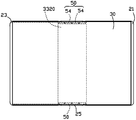
- FIG. 7 is a schematic front structural diagram of an electronic device in a fifth embodiment of the present application.
- FIG. 8 is a schematic front structural diagram of an electronic device in a sixth embodiment of the present application.
- FIG. 9 is a schematic front structural diagram of an electronic device in a seventh embodiment of the present application.
- FIG. 10 is a schematic front structural diagram of an electronic device in an eighth embodiment of the present application.
- FIG. 11 is a schematic front structural diagram of an electronic device in a ninth embodiment of the present application.
- FIG. 12 is a schematic front structural diagram of an electronic device in a tenth embodiment of the present application.
- FIG. 13 is a flowchart of a method of manufacturing a flexible display device of an electronic device of the present application.
- FIG. 1 is a schematic diagram of the three-dimensional structure of the electronic device in the first embodiment of the present application
- FIG. 2 is a schematic diagram of the front structure of the electronic device in FIG. 1; -Part III cross-section structure diagram.
- the electronic device 100 in the first embodiment of the present application includes a casing 20 and a flexible display device 30 disposed on the casing 20.
- the housing 20 includes a first frame body 21, a second frame body 23, and a hinge 25 connected between the first frame body 21 and the second frame body 23.
- the flexible display device 30 is disposed on the first frame body 21, the second frame body 23, and the hinge 25.
- the flexible display device 30 includes a support piece 31 disposed on the hinge 25, and is disposed on the hinge frame 25.
- the flexible screen 33 includes a screen body 332 and a protective layer 334 fixedly attached to the back of the screen body 332.
- the screen body 332 includes a bendable area 3320, and the back surface of the protective layer 334 is provided with an elastic adhesive 50 between the bendable area 3320 and the support sheet 31.
- the elastic adhesive 50 Located between or near the outside of the flexible screen 33 and the corresponding outside of the support sheet 31.
- the elastic adhesive 50 connects the support sheet 31 to the protective layer 334.
- the back surface of the flexible screen 332 can be prevented from being directly contacted with the support sheet 31 and abraded; in addition, the support sheet 31 and the protection layer 334 An elastic adhesive 50 is provided therebetween, which can also reduce external dust from entering between the support sheet 31 and the flexible screen 33.
- the front of the flexible screen 33 indicates a smooth surface
- the back of the flexible screen 33 refers to a surface facing away from the light-emitting surface
- the outside of the flexible screen 33 and the outside of the support sheet 31 both refer to a light surface. Includes the outermost edge and the area near the outermost edge.
- the supporting sheet 31 is a thin steel sheet that can be bent
- the elastic backing adhesive 50 is a double-sided adhesive tape, a solid adhesive, a glue, or the like.
- the electronic device 100 is a mobile phone. It can be understood that, in other embodiments, the electronic device 100 may be, but is not limited to, a PDA of a radio telephone, a pager, a web browser, a notepad, a calendar, and / or a global positioning system (GPS) receiver.
- a PDA of a radio telephone
- a pager a web browser
- a notepad a calendar
- / or a global positioning system (GPS) receiver GPS
- a protective layer 334 is provided on the back of the screen body 332 of the electronic device 100 of the present application.
- An elastic backing 50 is provided in the bendable area 3320 corresponding to the protective layer 334 and the support sheet 31.
- the adhesive 50 can seal the gap between the support plate 31 and the flexible screen 332 to prevent foreign matters such as dust and particles from entering between the support plate 31 and the flexible screen 332.
- the protective layer 334 can also prevent the back surface of the flexible screen 332 from abrasion, and the elastic adhesive 50 can prevent the flexible screen 33 from being separated from the supporting sheet 31 to prevent the flexible screen 33 from displaying failure or damage.
- the elastic adhesive 50 is sandwiched between the protective layer 334 and the support sheet 31 on the left and right sides of the region of the bendable region 3320.
- the protective layer 334 can be slidably laminated between the region corresponding to the bendable region 3320 and the support sheet 31 through the elastic backing 50.
- the protective layer 334 can prevent the support sheet 31 from abrading the screen body 332. the back of.
- the width of the support sheet 31 is smaller than the width of the protective layer 334, that is, the left and right sides of the protective layer 334 extend from the left and right sides of the support sheet 31, respectively.
- the left and right sides are two outer sides of the bendable area 3320 of the electronic device 100.
- the back surface of the protective layer 334 is provided with the elastic backing 50 adjacent to the left and right sides of the supporting sheet 31, and the two elastic backings 50 are respectively disposed on the supporting sheet 31 and the protective layer.
- the left and right sides of the bendable region 3320 between 334 can reduce dust from entering between the support sheet 31 and the protective layer 334.
- the protective layer 334 is a liquid metal sheet, and the liquid metal sheet is fixedly attached to the back of the screen body 332.
- the protective layer 334 may be a wear-resistant plastic sheet or a wear-resistant rubber sheet fixedly attached to the back of the screen body 332.
- the screen body 332 includes a flexible screen plate 3321, a cover plate 3323 laminated on the front surface of the flexible screen plate 3321, and a light-shielding black plastic layer 3325 laminated on the back surface of the flexible screen plate 3321.
- the protective layer 334 is attached to a side of the light-shielding black adhesive layer 3325 facing away from the flexible screen plate 3321.
- the width of the cover plate 3323 is greater than the width of the flexible screen plate 3321, that is, the left and right sides of the cover plate 3323 extend from the left and right sides of the flexible screen plate 3321, respectively.
- the light-shielding black layer 3325 and the flexible screen 3332 have the same width.
- the width of the screen body 332 is smaller than the width of the protection layer 334 and is retracted relative to the protection layer 334, which is beneficial to the protection layer 334 to better protect the screen body 332.
- the width of the supporting sheet 31 is the same as the width of the protective layer 334.
- the elastic backing adhesive 50 has a long shape, and the elastic backing adhesive 50 extends along the outer side of the supporting sheet 31, that is, the elastic backing adhesive 50 extends along the length direction of the screen body 332.
- the elastic adhesive 50 seals the gap between the support sheet 31 and the protective layer 334 to prevent dust from entering between the support sheet 31 and the protective layer 334.
- the elastic adhesive 50 is a fixed adhesive strip.
- each elastic adhesive 50 extends along the left and right outer sides of the support sheet 31 in the bendable area 3320; and the flexible screen 33 is laminated on the support sheet 31.
- the other side of the elastic adhesive 50 is adhered to the back surface of the protective layer 334, and the two elastic adhesives 50 are respectively adjacent to the left and right sides of the protective layer 334.
- the two elastic adhesives 50 are sandwiched between the support sheet 31 and the protective layer 334, and the elastic adhesive 50 connects the support sheet 31 and the flexible screen 33 to prevent The flexible screen 33 is separated from the supporting sheet 31.
- the elastic backing can also be pasted on the back of the protective layer, and then on the front of the support sheet to achieve the same effect.
- FIG. 4 is a schematic cross-sectional structure diagram of an electronic device in a second embodiment of the present application.
- the structure of the second embodiment of the electronic device of the present application is similar to that of the first embodiment, except that in the second embodiment, the surface of the support sheet 31 facing the protection layer 334 is adjacent to the protection layer.
- a receiving groove 312 is respectively provided at the left and right sides of the 334, and the two elastic adhesives 50 are respectively received and attached to the two receiving grooves 312.
- Each of the elastic adhesives 50 faces the protective layer 334.
- the surface of the support sheet 334 facing the protection layer 334 is exposed from the surface, so that each elastic adhesive 50 is attached to the protection layer 334.
- Each receiving groove 312 extends along a corresponding outer side of the supporting sheet 31, that is, each receiving groove 312 extends along a length direction of the screen body 332.
- the depth of each receiving groove 312 is slightly smaller than the thickness of the elastic adhesive 50.
- each receiving groove 312 is rectangular, and the cross section of the elastic adhesive 50 is also rectangular.
- the receiving groove 312 can increase the contact area between the elastic adhesive 50 and the supporting sheet 334, so that the elastic adhesive 50 can be more firmly adhered to the supporting sheet 31 and the protective layer 334; and
- the elastic adhesive 50 is partially accommodated in the receiving groove 312 so that the thickness of the flexible display device 30 can be reduced, so that the thickness of the electronic device 100 can be reduced, which is convenient to carry and use.
- each receiving groove 312 may be triangular, semi-circular, polygonal, or irregular in shape
- the cross-section of the elastic adhesive 50 may be triangular, semi-circular, polygonal, or irregular in shape.
- FIG. 5 is a schematic cross-sectional structure diagram of an electronic device according to a third embodiment of the present application.
- the structure of the third embodiment of the electronic device of the present application is similar to that of the first embodiment, except that in the third embodiment, the protective layer 334 faces the surface of the support sheet 31 and is adjacent to the support.
- the left and right sides of the sheet 31 are respectively provided with receiving grooves 3341, and the two elastic adhesives 50 are respectively received and attached to the two receiving grooves 3341, and each of the elastic adhesives 50 faces the supporting sheet.
- the surface of 31 is exposed to the surface of the protective layer 334 facing the supporting sheet 31, so that each elastic adhesive 50 is attached to the supporting sheet 31.
- Each receiving groove 3341 extends along the corresponding side of the protective layer 334, that is, the receiving groove 3341 extends along the length direction of the screen body 332.
- the depth of each receiving groove 3341 is slightly smaller than the thickness of the elastic adhesive 50.
- each receiving groove 3341 is rectangular, and the cross section of the elastic adhesive 50 is also rectangular.
- the receiving groove 3341 can increase the contact area of the elastic adhesive 50 and the protective layer 334, so that the adhesive of the elastic adhesive 50 to the protective layer 334 and the support sheet 31 is stronger; and
- the elastic adhesive 50 is partially contained in the receiving groove 3341, which can reduce the thickness of the flexible display device 30, thereby reducing the thickness of the electronic device 100, which is convenient to carry and use.
- each receiving slot 3341 may be triangular, semi-circular, polygonal, or irregular in shape
- the cross-section of the elastic adhesive 50 may be triangular, semi-circular, polygonal, or irregular in shape.
- FIG. 6 is a partial cross-sectional structural diagram of an electronic device in a fourth embodiment of the present application.
- the structure of the fourth embodiment of the electronic device of the present application is similar to that of the second embodiment, except that in the fourth embodiment, the protective layer 334 and the supporting sheet 31 are provided with corresponding sides on opposite sides. That is, the side of the protective layer 334 facing the supporting sheet 31 is provided with receiving grooves 3341 adjacent to the left and right sides, and the supporting sheet 31 is provided with a corresponding receiving side facing the side of the protective layer 334. Two receiving slots 312 of the slot 3341.
- each elastic adhesive 50 is received and attached to the receiving groove 3341 of the protective layer 334, and another portion of the elastic adhesive 50 is received and attached to the receiving groove 312 of the support sheet 31.
- the elastic adhesive 50 can increase the adhesion area with the protective layer 334 and the support sheet 31, so that the adhesive between the elastic adhesive 50 and the protective layer 334 and the support sheet 31 is stronger, and can be changed.
- the thickness of the flexible display device 30 is reduced, that is, the elastic adhesive 50 does not occupy the thickness of the flexible display device 30.
- FIG. 7 is a schematic diagram of a front structure of an electronic device in a fifth embodiment of the present application.
- the structure of the fifth embodiment of the electronic device of the present application is similar to that of the first embodiment, except that in the fifth embodiment, the back surface of the protective layer 334 is adjacent to the left and right sides of the support sheet 31
- Each of the elastic adhesive sheets 50 includes a plurality of elastic adhesive sheets 54, and a plurality of elastic adhesive sheets 54 on the same side are distributed along the corresponding side of the support sheet 31, that is, a plurality of elastic adhesive sheets 54 on the same side are along the screen body 332. Lengthwise.
- a plurality of elastic backing sheets 54 on the same side are linearly arranged along the sides of the support sheet 31, and adjacent elastic backing sheets 54 on the same side are separated from each other by a gap.
- the length of the gap ie, the distance between adjacent elastic backing sheets is smaller than the length of the elastic backing sheet 54.
- a plurality of elastic backing sheets 54 on the same side are arranged along the corresponding sides of the supporting sheet 31.
- the elastic backing sheets 54 in this embodiment can not only make the supporting sheet 31 and the protective layer 334 firmly connected, but also save the amount of the elastic backing sheet 50.
- the elastic backing sheets 54 are independent of each other, even if one elastic backing sheet 54 fails, the elastic backing sheet 54 in other positions will not be involved, thereby making the structure of the entire electronic device 100 more stable.
- the supporting sheet 31 faces the protective layer 334, and a plurality of receiving slots are respectively formed on the surface adjacent to the left and right sides of the protective layer 334.
- Each receiving slot receives and attaches an elastic back.
- a film 54, each of the elastic backing films 54 facing the surface of the protective layer 334 exposes the surface of the supporting sheet 31 facing the protective layer 334, so that each elastic backing film is attached to the protective layer 334 .
- a plurality of receiving slots are respectively formed on the surface of the protective layer 334 facing the supporting sheet 31 adjacent to the left and right sides of the supporting sheet 31.
- Each receiving slot receives and is attached with an elastic back.
- FIG. 8 is a schematic diagram of a front structure of an electronic device in a sixth embodiment of the present application.
- the structure of the sixth embodiment of the electronic device of the present application is similar to that of the first embodiment, except that in the sixth embodiment, the protective layer 334 and the support sheet 31 are in a bendable area 3320.
- a plurality of spaced-apart adhesives 50 are provided in the space.
- Each of the elastics 50 is an elastic-backed strip, and each of the elastic-backed strips extends along the side of the support sheet 31, that is, each of the elastic-backed strips. 50 extends along the length of the screen body 332.
- a plurality of the elastic backing strips are spaced apart from each other in the width direction of the supporting sheet 31.
- the plurality of elastic backing strips can make the supporting sheet 31 and the protective layer 334 more firmly connected, thereby preventing the protective layer 334 from being folded
- the curved area 3320 is arched.
- FIG. 9 is a schematic diagram of a front structure of an electronic device in a seventh embodiment of the present application.
- the structure of the seventh embodiment of the electronic device of the present application is similar to that of the first embodiment, except that in the seventh embodiment, except for the left and right sides between the support sheet 31 and the protective layer 334, respectively.
- a plurality of spaced elastic adhesives 50 are arranged between the support sheet 31 and the protective layer 334 in the bendable area 3320, and the elastic adhesives 50 are arranged along the screen body.
- 332 is distributed in the width direction.
- Each elastic adhesive 50 includes a plurality of spaced elastic films 54, and a plurality of the elastic films 54 are distributed along the side of the supporting sheet 31, that is, a plurality of the elastic films 54 are along the length direction of the screen body 332.
- Array
- each elastic film 54 is rectangular.
- the plurality of elastic films 54 in this embodiment can make the support sheet 31 and the protective layer 334 more firmly connected, and can save the amount of the elastic film 50. Since each elastic film 54 is independent of each other, even if one elastic film 54 fails Also, the elastic backing film 54 in other positions will not be involved, thereby making the structure of the entire electronic device 100 more stable.
- FIG. 10 is a schematic diagram of a front structure of an electronic device in an eighth embodiment of the present application.
- the structure of the eighth embodiment of the electronic device of the present application is similar to that of the fifth embodiment, except that in the eighth embodiment, the left and right sides of the support sheet 31 and the protective layer 334 are provided respectively.
- the elastic adhesive 50 composed of a plurality of elastic films 54
- a plurality of spaced elastic adhesives 50 are provided between the support sheet 31 and the protective layer 334 in a bendable area 3320, and a plurality of the elastic adhesives 50 are provided. Distributed along the length direction of the screen body 332.
- Each elastic adhesive 50 includes a plurality of spaced elastic films 54, and a plurality of the elastic films 54 are distributed along the side of the supporting sheet 31, that is, a plurality of the elastic films 54 are along the length direction of the screen body 332.
- Array
- each elastic film 54 has a rectangular shape, and a plurality of elastic films 54 can make the supporting sheet 31 and the protective layer 334 more firmly connected, and can save the amount of the elastic backing 50.
- FIG. 11 is a schematic diagram of a front structure of an electronic device in a ninth embodiment of the present application.
- the structure of the ninth embodiment of the electronic device of the present application is similar to that of the seventh embodiment, except that in the ninth embodiment, the support piece 31 and the protective layer 334 are in a bendable area 3320.
- Each of the spaced-apart elastic back adhesives 50 includes a plurality of spaced-apart prism-shaped elastic films 54.
- the plurality of elastic films 54 can make the support sheet 31 and the protective layer 334 more firmly connected, and can save the amount of the elastic adhesive 50.
- FIG. 12 is a schematic diagram of a front structure of an electronic device in a tenth embodiment of the present application.
- the structure of the tenth embodiment of the electronic device of the present application is similar to that of the seventh embodiment, except that in the tenth embodiment, the support piece 31 and the protective layer 334 are in a bendable area 3320.
- Each of the spaced-apart elastic back adhesives 50 includes a plurality of spaced-apart circular elastic films 54.
- the plurality of elastic films 54 can make the support sheet 31 and the protective layer 334 more firmly connected, and can save the amount of the elastic adhesive 50.
- each of the elastic films 54 may be a polygon, an ellipse, or an irregular figure.
- the flexible screen of the present invention may not include or only include any one or more or all of a light-shielding black rubber layer, a protective layer, and a cover plate.
- the elastic adhesive 50 in each of the above embodiments has elasticity, so that the tensile deformation can occur when the supporting sheet 31 slides relative to the flexible screen 33.
- the elastic adhesive 50 due to its own The elasticity will automatically shrink and deform and return to the original state without being broken.
- a is the sliding distance of the support sheet 31 relative to the flexible screen 33
- b is the distance between the support sheet 31 and the flexible screen 33 in the thickness direction.
- the stretch of the elastic adhesive 50 meets It is set that when the supporting sheet 31 slides in a direction X relative to the flexible screen 33, and the thickness direction of the supporting sheet 31 is Y, when the supporting sheet 31 slides in relation to the flexible screen 33, the elastic adhesive 50 is inclined along the relative X and the thickness direction Y.
- the stretching direction of the elastic backing 50 is inclined to the sliding direction of the flexible screen 33 relative to the supporting sheet 31.
- the present application further provides a method for manufacturing a flexible display device, which includes the following steps:
- S1 providing a flexible display device 30 including a flexible screen 33 and a support sheet 31, the flexible screen 33 including a bendable area 3320;
- An elastic adhesive 50 is provided on the back of the flexible screen 33 between the bendable area 3320 and the support sheet 31.
- the elastic adhesive 50 is located on or near the outside of the flexible screen 33 and supports Position between the respective outer sides of the sheet 31.
- the flexible screen 33 and the supporting sheet 31 are connected through the elastic adhesive 50, and the elastic sheet 50 seals a gap between the supporting sheet 31 and the flexible screen 33.
- the elastic backing adhesive 50 is pasted on the front surface of the supporting sheet 31 adjacent to the left and right sides, and the back of the flexible screen 33 is laminated on the front surface of the supporting sheet 31 so that the elastic backing adhesive 50 is adhered to the support. Between the sheet 31 and the flexible screen 33.
- the elastic adhesive 50 on the same side includes a plurality of elastic adhesive films 54 arranged linearly along the length direction of the flexible screen 33. Adjacent elastic adhesive films 54 are separated from each other by a gap. Adjacent two elastic adhesive films 54 The length of the gap is smaller than the length of the elastic backing film 54.
- the front surface of the supporting sheet 31 is provided with receiving grooves 312 adjacent to the left and right sides.
- Two elastic backing adhesives 50 are respectively received and attached to the corresponding receiving grooves 312.
- Each of the elastic backing adhesives 312 exposes the supporting sheet 31.
- the front surface of the flexible screen 33 is convenient for each elastic adhesive 50 to be adhered to the back surface of the flexible screen 33.
- Receiving slots 3341 are provided on the back of the flexible screen 33 adjacent to the left and right sides. Two elastic adhesives 50 are respectively received and attached to the corresponding receiving grooves 3341. Each of the elastic adhesives 50 exposes the flexible screen 33. The back surface, so that each elastic backing adhesive 50 is adhered to the front surface of the supporting sheet 31.
- the front surface of the support sheet 31 and the back surface of the flexible screen 33 are provided with receiving grooves connected to each other adjacent to the left and right sides, and an elastic adhesive 50 is received and attached to the receiving grooves.
Landscapes
- Engineering & Computer Science (AREA)
- Theoretical Computer Science (AREA)
- Computer Hardware Design (AREA)
- Physics & Mathematics (AREA)
- General Engineering & Computer Science (AREA)
- General Physics & Mathematics (AREA)
- Human Computer Interaction (AREA)
- Signal Processing (AREA)
- Microelectronics & Electronic Packaging (AREA)
- Devices For Indicating Variable Information By Combining Individual Elements (AREA)
- Mathematical Physics (AREA)
- Liquid Crystal (AREA)
- Laminated Bodies (AREA)
- Electroluminescent Light Sources (AREA)
Abstract
一种电子装置(100),包括壳体(20)及柔性显示装置(30),壳体(20)包括第一框体(21)、第二框体(23)及连接于第一框体(21)与第二框体(23)之间的铰链(25),柔性显示装置(30)设置于第一框体(21)、第二框体(23)及铰链(25)上,柔性显示装置(30)包括支撑片(31)及设置于支撑片(31)上的柔性屏(33),柔性屏(33)包括可折弯区域(3320),柔性屏(33)的背面于可折弯区域(3320)内与支撑片(31)之间设置有弹性背胶(50),弹性背胶(50)位于或靠近柔性屏(33)的外侧与支撑片(31)的相应外侧之间的位置。弹性背胶(50)能防止灰尘、微粒等杂物进入支撑片(31)与柔性屏(33)之间,不易造成柔性屏(33)的背面磨损,且弹性背胶(50)能防止柔性屏(33)与支撑片(31)分离。
Description
本申请涉及电子设备的显示装置领域,尤其涉及一种柔性显示装置、设置有所述柔性显示装置的电子装置,以及柔性显示装置的制造方法。
随着柔性屏的发展,现有技术中已经出现了折叠式显示屏的电子装置,现有的折叠式显示屏的电子装置一般通过铰链来实现柔性屏的弯折,通过支撑板与柔性屏的背面贴合以实现对柔性屏的支撑,所述支撑板与所述柔性屏之间是滑动贴合,以方便所述屏体的折弯或展平。然而,由于所述支撑板与所述柔性屏之间为滑动贴合,即,所述支撑板与所述柔性屏之间有细缝,因此,外部的灰尘、微粒等杂物容易进入所述支撑板与所述柔性屏之间,从而造成柔性屏的磨损,影响所述显示屏的性能。
发明内容
本申请提供一种能防止柔性屏的背面磨损的柔性屏显示装置,设置有所述柔性屏显示装置的电子装置,以及柔性显示装置的制造方法。
本申请所述的一种柔性显示装置,包括支撑片,以及设置于所述支撑片上的柔性屏,所述柔性屏包括可折弯区域,所述柔性屏的背面于可折弯区域内与所述支撑片之间设置有弹性背胶,弹性背胶位于或靠近柔性屏的外侧与支撑片的相应外侧之间的位置。
本申请还提供一种电子装置,包括壳体及柔性显示装置,所述壳体包括第一框体、第二框体及连接于所述第一框体与所述第二框体之间的铰链,所述柔性显示装置设置于所述第一框体、第二框体及所述铰链上,所述柔性显示装置包括支撑片及设置于所述支撑片上的柔性屏,所述柔性屏包括可折弯区域,所述柔性屏的背面于可折弯区域内与所述支撑片之间设置有弹性背胶,弹性背胶位于或靠近柔性屏的外侧与支撑片的相应外侧之间的位置。
本申请还提供一种柔性显示装置的制作方法,包括:
提供包括有柔性屏及支撑片的柔性显示装置,所述柔性屏包括可折弯区域;及
在所述柔性屏的背面于所述可折弯区域内与所述支撑片之间设置有弹性背胶,所述弹性背胶位于或靠近柔性屏的外侧与支撑片的相应外侧之间的位置,通过所述弹性背胶连接所述柔性屏与所述支撑片。
本申请电子装置的所述柔性屏的背面于可折弯区域内与所述支撑片之间设置有弹性背胶,弹性背胶位于或靠近柔性屏的外侧与支撑片的相应外侧之间的位置,因此,所述弹性背胶能防止灰尘、微粒等杂物进入所述支撑板与所述柔性屏之间,当所述电子装置通过所述铰链折弯或展平时,不易造成所述柔性屏的背面磨损,且所述弹性背胶能防止所述柔性屏与所述支撑片分离。
为了更清楚地说明本发明实施例中的技术方案,下面将对实施例中所需要使用的附图作简单地介绍,显而易见地,下面描述中的附图仅仅是本发明的一些实施例,对于本领域普通技术人员来讲,在不付出创造性劳动的前提下,还可以根据这些附图获得其他的附图。
图1是本申请第一实施例中的电子装置的立体结构示意图。
图2是图1中的电子装置的正面结构示意图。
图3是图1中沿III-III线的部分剖视结构示意图。
图4是本申请第二实施例中的电子装置的部分剖视结构示意图。
图5是本申请第三实施例中的电子装置的部分剖视结构示意图。
图6是本申请第四实施例中的电子装置的部分剖视结构示意图。
图7是本申请第五实施例中的电子装置的正面结构示意图。
图8是本申请第六实施例中的电子装置的正面结构示意图。
图9是本申请第七实施例中的电子装置的正面结构示意图。
图10是本申请第八实施例中的电子装置的正面结构示意图。
图11是本申请第九实施例中的电子装置的正面结构示意图。
图12是本申请第十实施例中的电子装置的正面结构示意图。
图13是本申请电子装置的柔性显示装置的制造方法的流程。
下面将结合本发明实施例中的附图,对本发明实施例中的技术方案进行清楚、完整地描述,显然,所描述的实施例仅是本发明一部分实施例,而不是全部的实施例。基于本发明中的实施例,本领域普通技术人员在没有做出创造性劳动前提下所获得的所有其他实施例,都属于本发明保护的范围。
本发明实施例的描述中,需要理解的是,术语“上”、“下”“左”“右”等指示的方位或位置关系为基于附图所示的方位或位置关系,仅是为了便于描述本发明和简化描述,而不是暗示或指示所指的装置或元件必须具有特定的方位、以特定的方位构造和操作,因此不能理解为对本发明的限制。
本发明实施例的描述中,需要理解的是,术语“厚度”等指示的方位或位置关系为基于附图所示的方位或位置关系,仅是为了便于描述本发明和简化描述,而不是暗示或指示所指的装置或元件必须具有特定的方位、以特定的方位构造和操作,因此不能理解为对本发明的限制。
请一并参阅图1至图3,图1是本申请第一实施例中的电子装置的立体结构示意图;图2是图1中的电子装置的正面结构示意图;图3是图1中沿III-III线的部分剖视结构示意图。本申请的第一实施例中的电子装置100,其包括一壳体20及设置于所述壳体20上的一柔性显示装置30。所述壳体20包括一第一框体21、一第二框体23及连接于所述第一框体21与所述第二框体23之间的一铰链25。所述柔性显示装置30设置于所述第一框体21、第二框体23及铰链25上,所述柔性显示装置30包括设置于所述铰链25上的一支撑片31,以及设置于所述支撑片31上的一柔性屏33。所述柔性屏33包括一屏体332及固定贴合于所述屏体332背面的一保护层334。所述屏体332包括一可折弯区域3320,所述保护层334的背面在所述可折弯区域3320内与所述支撑片31之间设置有弹性背胶50,所述弹性背胶50位于或靠近柔性屏33的外侧与支撑片31的相应外侧之间的位置。所述弹性背胶50将所述支撑片31与所述保护层334连接,当所述电子装置100通过所述铰链25折弯或展开时,所述支撑片31与所述柔性屏33的保护层334相对移动,所述弹性背胶50也发生弹性变形。由于所述屏体332的背面设置有保护层 334,因此,能防止所述柔性屏332的背面直接与所述支撑片31接触而被磨损;另外,所述支撑片31与所述保护层334之间设置有弹性背胶50,也能减少外部灰尘进入所述支撑片31与所述柔性屏33之间。本实施例中,所述柔性屏33的正面指出光面,所述柔性屏33的背面指背朝所述出光面的面;所述柔性屏33的外侧及所述支撑片31的外侧均指包括最外面的边缘及靠近最外面边缘的区域。
本实施例中,所述支撑片31是能弯曲的薄钢片,所述弹性背胶50为双面胶、固体胶、胶水等胶条。
本实施例中,所述电子装置100为手机。可以理解,在其它实施例中,电子装置100可以是但不限于无线电电话、寻呼机、Web浏览器、记事簿、日历以及/或全球定位系统(GPS)接收器的PDA。
本申请电子装置100的屏体332的背面设置有保护层334,所述保护层334对应的所述可折弯区域3320内与所述支撑片31之间设置有弹性背胶50,所述弹性背胶50能密封所述支撑板31与所述柔性屏332之间的间隙,以防止灰尘、微粒等杂物进入所述支撑板31与所述柔性屏332之间。当所述电子装置100通过所述铰链25折弯或展平时,不易造成柔性屏332的磨损,另外,所述保护层334也能防止所述柔性屏332的背面磨损,且所述弹性背胶50能防止所述柔性屏33与所述支撑片31分离,以防止所述柔性屏33显示失效或损坏。
如图3所示,所述保护层334与所述支撑片31之间于所述可折弯区域3320的区域的左右两侧分别夹持有所述弹性背胶50。所述保护层334对应所述可折弯区域3320的区域与所述支撑片31之间通过弹性背胶50可滑动层叠,所述保护层334能防止所述支撑片31磨损所述屏体332的背面。
本实施例中,所述支撑片31的宽度小于所述保护层334的宽度,即,所述保护层334的左右两侧分别延伸出所述支撑片31的左右两侧。所述左右两侧为所述电子装置100的可折弯区域3320的两外侧。所述保护层334的背面邻近所述支撑片31的左右两侧边处分别设置有所述弹性背胶50,两个所述弹性背胶50分别设置于所述支撑片31与所述保护层334之间的可折弯区域3320的左右两侧处,从而能减少灰尘进入所述支撑片31与所述保护层334之间。
本实施例中,所述保护层334是液态金属片,所述液态金属片固定贴合于 所述屏体332的背面。
在其他实施例中,所述保护层334可以是固定贴合于所述屏体332背面的耐磨塑胶片或耐磨橡胶片等。
所述屏体332包括一柔性屏板3321、层叠于所述柔性屏板3321正面的一盖板3323,以及层叠于所述柔性屏板3321的背面的一遮光黑胶层3325。所述保护层334贴合于所述遮光黑胶层3325背朝所述柔性屏板3321的侧面。所述盖板3323的宽度大于所述柔性屏板3321的宽度,即,所述盖板3323的左右两侧分别延伸出所述柔性屏板3321的左右两侧。所述遮光黑胶层3325及所述柔性屏板3321的宽度相同。
本实施例中,所述屏体332的宽度小于所述保护层334的宽度而相对于所述保护层334内缩,有利于所述保护层334更好地保护所述屏体332。
在其他实施例中,所述支撑片31的宽度与所述保护层334的宽度相同。
所述弹性背胶50为长条形状,所述弹性背胶50沿所述支撑片31的外侧边延伸,即,所述弹性背胶50沿所述屏体332的长度方向延伸。所述弹性背胶50密封所述支撑片31与所述保护层334之间的间隙,以防止灰尘进入所述支撑片31与所述保护层334之间。
所述弹性背胶50为固定胶条,安装所述弹性背胶50时,先将两个所述弹性背胶50的一侧分别粘贴于所述支撑片31的正面邻近所述支撑片31的左右侧边处,使每一弹性背胶50沿所述支撑片31的左右外侧边在所述可折弯区域3320内延伸;再将所述柔性屏33层叠于所述支撑片31上,使弹性背胶50的另一侧粘贴于所述保护层334的背面,且两个所述弹性背胶50分别邻近所述保护层334的左右侧边处。此时,两个所述弹性背胶50被夹持于所述支撑片31与所述保护层334之间,所述弹性背胶50连接所述支撑片31与所述柔性屏33,以防止所述柔性屏33与所述支撑片31分离。当然,在其他的实施方式当中,也可以先将弹性背胶贴在保护层的背面,再贴在支撑片的正面,可实现同样的效果。
请参阅图4,图4是本申请第二实施例中的电子装置的部分剖视结构示意图。本申请电子装置的第二实施例的结构与第一实施例的结构相似,不同之处在于:第二实施例中,所述支撑片31面朝所述保护层334的表面邻近所述保 护层334的左右侧边处分别开设有一收容槽312,两个所述弹性背胶50分别收容并贴接于两个所述收容槽312内,每一弹性背胶50面朝所述保护层334的表面外露出所述支撑片334面朝所述保护层334的表面,以便于每一弹性背胶50贴接于所述保护层334。
每一收容槽312沿所述支撑片31对应的外侧边延伸,即,每一收容槽312沿所述屏体332的长度方向延伸。每一收容槽312的深度略小于所述弹性背胶50的厚度,当所述弹性背胶50收容并贴接于所述收容槽312内时,所述弹性背胶50部分外露出所述支撑片31的面朝所述保护层334的表面。
本实施例中,每一收容槽312的横截面呈矩形,所述弹性背胶50的横截面也呈矩形。所述收容槽312能增大所述弹性背胶50与所述支撑片334的接触面积,从而使所述弹性背胶50与所述支撑片31及所述保护层334的粘贴更牢固;且所述弹性背胶50部分收容于所述收容槽312内能使所述柔性显示装置30的厚度变少,从而能使所述电子装置100的厚度变少,方便携带和使用。
在其他实施例中,每一收容槽312的横截面可以呈三角形、半圆形、多边形或不规则图形,弹性背胶50的横截面对应呈三角形、半圆形、多边形或不规则图形。
请参阅图5,图5是本申请第三实施例中的电子装置的部分剖视结构示意图。本申请电子装置的第三实施例的结构与第一实施例的结构相似,不同之处在于:第三实施例中,所述保护层334面朝所述支撑片31的表面于邻近所述支撑片31的左右两侧边处分别开设有一收容槽3341,两个所述弹性背胶50分别收容并贴接于两个所述收容槽3341内,每一弹性背胶50面朝所述支撑片31的表面外露出所述保护层334面朝所述支撑片31的表面,以便每一弹性背胶50贴接于所述支撑片31。
每一收容槽3341沿所述保护层334对应的侧边延伸,即,所述收容槽3341沿所述屏体332的长度方向延伸。每一收容槽3341的深度略小于所述弹性背胶50的厚度,当所述弹性背胶50收容并贴接于所述收容槽3341内时,所述弹性背胶50部分外露出所述保护层334面朝所述支撑片31的表面。
本实施例中,每一收容槽3341的横截面呈矩形,所述弹性背胶50的横截面也呈矩形。所述收容槽3341能增大所述弹性背胶50与所述保护层334的接 触面积,从而使所述弹性背胶50与所述保护层334及所述支撑片31的粘贴更牢固;且所述弹性背胶50部分收容于所述收容槽3341内能使所述柔性显示装置30的厚度变少,从而能使所述电子装置100的厚度变少,方便携带和使用。
在其他实施例中,每一收容槽3341的横截面可以呈三角形、半圆形、多边形或不规则图形,弹性背胶50的横截面对应呈三角形、半圆形、多边形或不规则图形。
请参阅图6,图6是本申请第四实施例中的电子装置的部分剖视结构示意图。本申请电子装置的第四实施例的结构与第二实施例的结构相似,不同之处在于:第四实施例中,所述保护层334与所述支撑片31相对的侧面上开设有相互对应的收容槽,即,所述保护层334面朝所述支撑片31的侧面邻近左右侧边处分别开设有收容槽3341,所述支撑片31面朝所述保护层334的侧面开设有对应收容槽3341的两个收容槽312。每一弹性背胶50的一部分收容并贴接于所述保护层334的收容槽3341内,所述弹性背胶50的另一部分收容并贴接于所述支撑片31的收容槽312内。所述弹性背胶50能增大与所述保护层334及所述支撑片31的粘贴面积,使弹性背胶50与所述保护层334及所述支撑片31的粘贴更牢固,且能变少所述柔性显示装置30的厚度,即,所述弹性背胶50不占用所述柔性显示装置30的厚度。
请参阅图7,图7是本申请第五实施例中的电子装置的正面结构示意图。本申请电子装置的第五实施例的结构与第一实施例的结构相似,不同之处在于:第五实施例中,所述保护层334的背面邻近所述支撑片31的左右两侧边处的所述弹性背胶50均包括若干弹性背胶片54,同一侧的若干弹性背胶片54沿支撑片31对应的侧边分布,即,同一侧的若干弹性背胶片54沿所述屏体332的长度方向延伸。同一侧的多个弹性背胶片54沿着支撑片31的侧边线性排列,同一侧相邻的弹性背胶片54之间通过间隙相互隔开。间隙的长度(即相邻弹性背胶片之间的距离)小于弹性背胶片54的长度。
本实施例中,同一侧的若干弹性背胶片54沿所述支撑片31对应的侧边排列。本实施例中的若干弹性背胶片54不仅能使支撑片31与保护层334连接牢固,且能节省弹性背胶50的用量。并且,由于各弹性背胶片54为相互独立,即使一个弹性背胶片54失效,也不会牵连其他位置的弹性背胶片54,从而使 得电子装置整体100的结构更为稳固。
在其他实施例中,所述支撑片31面朝所述保护层334的表面邻近所述保护层334的左右侧边处分别开设有若干收容槽,每一收容槽内收容并贴接有弹性背胶片54,每一弹性背胶片54面朝所述保护层334的表面外露出所述支撑片31面朝所述保护层334的表面,以便于每一弹性背胶片贴接于所述保护层334。
在其他实施例中,所述保护层334面朝所述支撑片31的表面邻近所述支撑片31的左右侧边处分别开设有若干收容槽,每一收容槽内收容并贴接有弹性背胶片54,每一弹性背胶片54面朝所述支撑片31的表面外露出所述保护层334面朝所述支撑片31的表面,以便每一弹性背胶片54贴接于所述支撑片31。
请参阅图8,图8是本申请第六实施例中的电子装置的正面结构示意图。本申请电子装置的第六实施例的结构与第一实施例的结构相似,不同之处在于:第六实施例中,所述保护层334与所述支撑片31之间在可折弯区域3320内设置有相互间隔的若干弹性背胶50,每一弹性背胶50是弹性背胶条,每一弹性背胶条沿所述支撑片31的侧边的方向延伸,即,每一弹性背胶50沿所述屏体332的长度方向延伸。
本实施例中,若干所述弹性背胶条沿所述支撑片31的宽度方向间隔阵列,若干弹性背胶条能使支撑片31与保护层334连接更牢固,从而防止保护层334在可折弯区域3320发生拱起的现象。
请参阅图9,图9是本申请第七实施例中的电子装置的正面结构示意图。本申请电子装置的第七实施例的结构与第一实施例的结构相似,不同之处在于:在第七实施例中,除了所述支撑片31与保护层334之间的左右侧边处分别设置有弹性背胶50外,所述支撑片31与保护层334之间于可折弯区域3320内还设置有若干相互间隔的弹性背胶50,若干所述弹性背胶50沿所述屏体332的宽度方向分布。每一弹性背胶50包括若干间隔的弹性胶片54,若干所述弹性胶片54沿所述支撑片31的侧边的方向分布,即,若干所述弹性胶片54沿所述屏体332的长度方向阵列。
本实施例中,每一弹性胶片54呈矩形。本实施例中的若干弹性胶片54 能使支撑片31与保护层334连接更牢固,且能节省弹性背胶50的用量,且由于各弹性背胶片54为相互独立,即使一个弹性背胶片54失效,也不会牵连其他位置的弹性背胶片54,从而使得电子装置整体100的结构更为稳固。
请参阅图10,图10是本申请第八实施例中的电子装置的正面结构示意图。本申请电子装置的第八实施例的结构与第五实施例的结构相似,不同之处在于:在第八实施例中,除了支撑片31与保护层334之间的左右侧边处分别设置有由若干弹性胶片54构成的弹性背胶50外,所述支撑片31与保护层334之间于可折弯区域3320内还设置有若干相互间隔的弹性背胶50,若干所述弹性背胶50沿所述屏体332的长度方向分布。每一弹性背胶50包括若干间隔的弹性胶片54,若干所述弹性胶片54沿所述支撑片31的侧边的方向分布,即,若干所述弹性胶片54沿所述屏体332的长度方向阵列。
本实施例中,每一弹性胶片54呈矩形,若干弹性胶片54能使支撑片31与保护层334连接更牢固,且能节省弹性背胶50的用量。
请参阅图11,图11是本申请第九实施例中的电子装置的正面结构示意图。本申请电子装置的第九实施例的结构与第七实施例的结构相似,不同之处在于:在第九实施例中,所述支撑片31与保护层334之间于可折弯区域3320内的若干相互间隔的弹性背胶50均包括若干相互间隔的棱形的弹性胶片54。若干弹性胶片54能使支撑片31与保护层334连接更牢固,且能节省弹性背胶50的用量。
请参阅图12,图12是本申请第十实施例中的电子装置的正面结构示意图。本申请电子装置的第十实施例的结构与第七实施例的结构相似,不同之处在于:在第十实施例中,所述支撑片31与保护层334之间于可折弯区域3320内的若干相互间隔的弹性背胶50均包括若干相互间隔的圆形的弹性胶片54。若干弹性胶片54能使支撑片31与保护层334连接更牢固,且能节省弹性背胶50的用量。
在其他实施例中,每一弹性胶片54还可以是多边形、椭圆形或不规则图形等。
可以理解地,除屏体外,本发明的柔性屏也可以不包含或仅包含遮光黑胶层、保护层及盖板其中的任一种或多种或所有。
上述各实施例的弹性背胶50具有弹性,因而可以在支撑片31相对柔性屏33滑动时产生拉伸形变,当支撑片31与柔性屏33的相对位置恢复时,弹性背胶50由于自身的弹性将自动收缩形变恢复初始状态,而不会出现被拉断的情况。进一步地,弹性背胶50的形变程度与支撑片31相对柔性屏33的滑动距离成比例关系,即满足c
2=a
2+b
2,其中c为弹性背胶50拉伸变形之后的长度,a为支撑片31相对于柔性屏33的滑动距离,b为支撑片31与柔性屏33之间在厚度方向上的距离。换句话说,弹性背胶50的拉伸幅度满足
 设定当支撑片31相对柔性屏33滑动方向为X,支撑片31的厚度方向为Y,当支撑片31相对柔性屏33滑动时,弹性背胶50沿着相对X及厚度方向Y均倾斜的方向拉伸变形,所述弹性背胶50的拉伸方向倾斜于柔性屏33相对支撑片31的滑动方向。
请参阅图13,本申请还提供一种柔性显示装置的制作方法,其包括如下步骤:
S1:提供包括有柔性屏33及支撑片31的柔性显示装置30,所述柔性屏33包括可折弯区域3320;及
S2:在所述柔性屏33的背面于所述可折弯区域3320内与所述支撑片31之间设置有弹性背胶50,所述弹性背胶50位于或靠近柔性屏33的外侧与支撑片31的相应外侧之间的位置。
通过所述弹性背胶50连接所述柔性屏33与所述支撑片31,且所述弹性背胶50密封所述支撑片31与所述柔性屏33之间的间隙。
在所述支撑片31的正面邻近左右侧边处粘贴有所述弹性背胶50,将所述柔性屏33的背面层叠于所述支撑片31的正面,使弹性背胶50粘贴于所述支撑片31与所述柔性屏33之间。
同一侧的弹性背胶50包括沿所述柔性屏33的长度方向线性排列的若干弹性背胶片54,相邻的弹性背胶片54之间通过间隙相互隔开,相邻的两个弹性背胶54之间的间隙的长度小于弹性背胶片54的长度。
所述支撑片31的正面邻近左右侧边处开设有收容槽312,两个弹性背胶50分别收容并贴接于对应的收容槽312内,每一弹性背胶外312露出所述支撑片31的正面,以便于每一弹性背胶50粘贴所述柔性屏33的背面。
在柔性屏33的背面邻近左右侧边处开设有收容槽3341,两个弹性背胶50分别收容并贴接于对应的收容槽3341内,每一弹性背胶50外露出所述柔性屏33的背面,以便于每一弹性背胶50粘贴所述支撑片31的正面。
所述支撑片31的正面与所述柔性屏33的背面于邻近左右侧边处开设有相互连通的收容槽,弹性背胶50收容并贴接于所述收容槽内。
以上所述是本发明的优选实施方式,应当指出,对于本技术领域的普通技术人员来说,在不脱离本发明原理的前提下,还可以做出若干改进和润饰,这些改进和润饰也视为本发明的保护范围。
Claims (25)
- 一种柔性显示装置,包括支撑片,以及设置于所述支撑片上的柔性屏,其特征在于,所述柔性屏包括可折弯区域,所述柔性屏的背面于可折弯区域内与所述支撑片之间设置有弹性背胶,弹性背胶位于或靠近柔性屏的外侧与支撑片的相应外侧之间的位置。
- 如权利要求1所述的柔性显示装置,其特征在于,所述柔性屏的背面邻近所述支撑片的左右两侧边处分别设置有弹性背胶。
- 如权利要求1所述的柔性显示装置,其特征在于,所述可折弯区域在弯曲时所述柔性屏的背面相对于支撑件滑动。
- 如权利要求2所述的柔性显示装置,其特征在于,所述弹性背胶为条形状,所述弹性背胶沿所述柔性屏的外侧的长度方向延伸。
- 如权利要求2所述的柔性显示装置,其特征在于,所述弹性背胶包括若干弹性背胶片,同一侧的若干所述弹性背胶片沿所述柔性屏的外侧的长度方向分布。
- 如权利要求5所述的柔性显示装置,其特征在于,同一侧的相邻弹性背胶片之间形成间隙,相邻弹性背胶片之间的距离小于弹性背胶片的长度。
- 如权利要求1所述的柔性显示装置,其特征在于,所述柔性屏包括柔性屏板及位于柔性屏板背面的保护层,保护层与支撑板滑动接触。
- 如权利要求7所述的柔性显示装置,其特征在于,所述支撑片面朝所述保护层的表面邻近所述保护层的左右两侧边处分别开设有收容槽,两个所述弹性背胶分别收容并贴接于对应的收容槽内,每一弹性背胶部分外露出所述支撑片面朝所述保护层的表面,以贴接于所述保护层。
- 如权利要求7所述的柔性显示装置,其特征在于,所述保护层面朝所述支撑片的表面邻近所述支撑片的左右两侧边处分别开设有收容槽,两个所述弹性背胶收容并贴接于所述收容槽内,每一弹性背胶部分外露出所述保护层面朝所述支撑片的表面,以贴接于所述支撑片。
- 如权利要求7至9任一所述的柔性显示装置,其特征在于,所述弹性背胶的厚度大于对应的收容槽的深度。
- 如权利要求7所述的柔性显示装置,其特征在于,所述保护层与所述 支撑片之间在所述可折弯区域内设置有相互间隔的若干弹性背胶。
- 如权利要求11所述的柔性显示装置,其特征在于,每一弹性背胶是弹性背胶条,所述弹性背胶条沿所述柔性屏的外侧的长度方向延伸。
- 如权利要求11所述的柔性显示装置,其特征在于,每一弹性背胶包括若干间隔的弹性胶片,若干所述弹性胶片沿所述柔性屏的外侧的长度方向分布。
- 如权利要求7所述的柔性显示装置,其特征在于,所述柔性屏弯曲时,所述支撑片与所述柔性屏的保护层在可折弯区域相对滑动,所述弹性背胶在柔性屏相对支撑片滑动时产生拉伸变形。
- 如权利要求1所述的柔性显示装置,其特征在于,所述弹性背胶拉伸变形的幅度满足其中a为柔性屏相对支撑片滑动的距离,b为柔性屏与支撑片之间沿着支撑片厚度方向的距离。

- 如权利要求7所述的柔性显示装置,其特征在于,所述弹性背胶的拉伸方向倾斜于保护层相对支撑片的滑动方向。
- 如权利要求7所述的柔性显示装置,其特征在于,所述保护层是液态金属片。
- 如权利要求1所述的柔性显示装置,其特征在于,所述弹性背胶为双面胶。
- 一种电子装置,包括壳体,其特征在于,所述电子装置还包括如权利要求1-18中任一项中所述的柔性显示装置,所述壳体包括第一框体、第二框体及连接于所述第一框体与所述第二框体之间的铰链,所述柔性显示装置设置于所述第一框体、第二框体及所述铰链上。
- 一种柔性显示装置的制作方法,包括:提供包括有柔性屏及支撑片的柔性显示装置,所述柔性屏包括可折弯区域;及在所述柔性屏的背面于所述可折弯区域内与所述支撑片之间设置有弹性背胶,所述弹性背胶位于或靠近柔性屏的外侧与支撑片的相应外侧之间的位置。
- 如权利要求20所述的柔性显示装置的制作方法,其特征在于,在所述支撑片的正面邻近左右侧边处粘贴有所述弹性背胶,将所述柔性屏的背面层 叠于所述支撑片的正面,使弹性背胶粘贴于所述支撑片与所述柔性屏之间。
- 如权利要求21所述的柔性显示装置的制作方法,其特征在于,同一侧的弹性背胶包括沿所述柔性屏的长度方向线性排列的若干弹性背胶片,相邻的弹性背胶片之间通过间隙相互隔开,间隙的长度小于弹性背胶片的长度。
- 如权利要求20所述的柔性显示装置的制作方法,其特征在于,所述支撑片的正面邻近左右侧边处开设有收容槽,两个弹性背胶分别收容并贴接于对应的收容槽内,每一弹性背胶外露出所述支撑片的正面,以便于每一弹性背胶粘贴所述柔性屏的背面。
- 如权利要求20所述的柔性显示装置的制作方法,其特征在于,所述柔性屏的背面邻近左右侧边处开设有收容槽,两个弹性背胶分别收容并贴接于对应的收容槽内,每一弹性背胶外露出所述柔性屏的背面,以便于每一弹性背胶粘贴所述支撑片的正面。
- 如权利要求20所述的柔性显示装置的制作方法,其特征在于,所述支撑片的正面与所述柔性屏的背面于邻近左右侧边处开设有相互连通的收容槽,弹性背胶收容并贴接于所述收容槽内。
Priority Applications (3)
| Application Number | Priority Date | Filing Date | Title |
|---|---|---|---|
| EP18922553.5A EP3809400A4 (en) | 2018-06-15 | 2018-07-24 | FLEXIBLE DISPLAY DEVICE, ELECTRONIC DEVICE AND METHOD FOR PRODUCING A FLEXIBLE DISPLAY DEVICE |
| CN201880093901.6A CN112585664A (zh) | 2018-06-15 | 2018-07-24 | 柔性显示装置、电子装置及柔性显示装置的制造方法 |
| US17/252,188 US11432415B2 (en) | 2018-06-15 | 2018-07-24 | Flexible display apparatus, electronic device and manufacturing method for flexible display apparatus |
Applications Claiming Priority (2)
| Application Number | Priority Date | Filing Date | Title |
|---|---|---|---|
| PCT/CN2018/091531 WO2019237340A1 (zh) | 2018-06-15 | 2018-06-15 | 柔性屏防尘机构、电子装置及柔性屏防尘机构的制造方法 |
| CNPCT/CN2018/091531 | 2018-06-15 |
Publications (1)
| Publication Number | Publication Date |
|---|---|
| WO2019237455A1 true WO2019237455A1 (zh) | 2019-12-19 |
Family
ID=65604305
Family Applications (8)
| Application Number | Title | Priority Date | Filing Date |
|---|---|---|---|
| PCT/CN2018/091531 Ceased WO2019237340A1 (zh) | 2018-06-15 | 2018-06-15 | 柔性屏防尘机构、电子装置及柔性屏防尘机构的制造方法 |
| PCT/CN2018/096872 Ceased WO2019237455A1 (zh) | 2018-06-15 | 2018-07-24 | 柔性显示装置、电子装置及柔性显示装置的制造方法 |
| PCT/CN2018/096871 Ceased WO2019237454A1 (zh) | 2018-06-15 | 2018-07-24 | 柔性显示装置、电子装置及柔性显示装置的制造方法 |
| PCT/CN2018/098644 Ceased WO2019237473A1 (zh) | 2018-06-15 | 2018-08-03 | 柔性显示装置、电子装置及柔性显示装置的制造方法 |
| PCT/CN2018/099730 Ceased WO2019237488A1 (zh) | 2018-06-15 | 2018-08-09 | 柔性显示装置及电子装置 |
| PCT/CN2018/110027 Ceased WO2019237598A1 (zh) | 2018-06-15 | 2018-10-12 | 显示装置、电子装置及电子装置的制造方法 |
| PCT/CN2018/112489 Ceased WO2019237632A1 (zh) | 2018-06-15 | 2018-10-29 | 柔性屏及其制备方法及柔性电子装置 |
| PCT/CN2018/122690 Ceased WO2019237706A1 (zh) | 2018-06-15 | 2018-12-21 | 柔性显示设备及柔性显示设备的制作方法 |
Family Applications Before (1)
| Application Number | Title | Priority Date | Filing Date |
|---|---|---|---|
| PCT/CN2018/091531 Ceased WO2019237340A1 (zh) | 2018-06-15 | 2018-06-15 | 柔性屏防尘机构、电子装置及柔性屏防尘机构的制造方法 |
Family Applications After (6)
| Application Number | Title | Priority Date | Filing Date |
|---|---|---|---|
| PCT/CN2018/096871 Ceased WO2019237454A1 (zh) | 2018-06-15 | 2018-07-24 | 柔性显示装置、电子装置及柔性显示装置的制造方法 |
| PCT/CN2018/098644 Ceased WO2019237473A1 (zh) | 2018-06-15 | 2018-08-03 | 柔性显示装置、电子装置及柔性显示装置的制造方法 |
| PCT/CN2018/099730 Ceased WO2019237488A1 (zh) | 2018-06-15 | 2018-08-09 | 柔性显示装置及电子装置 |
| PCT/CN2018/110027 Ceased WO2019237598A1 (zh) | 2018-06-15 | 2018-10-12 | 显示装置、电子装置及电子装置的制造方法 |
| PCT/CN2018/112489 Ceased WO2019237632A1 (zh) | 2018-06-15 | 2018-10-29 | 柔性屏及其制备方法及柔性电子装置 |
| PCT/CN2018/122690 Ceased WO2019237706A1 (zh) | 2018-06-15 | 2018-12-21 | 柔性显示设备及柔性显示设备的制作方法 |
Country Status (4)
| Country | Link |
|---|---|
| US (1) | US11432415B2 (zh) |
| EP (1) | EP3809400A4 (zh) |
| CN (14) | CN112513961A (zh) |
| WO (8) | WO2019237340A1 (zh) |
Families Citing this family (69)
| Publication number | Priority date | Publication date | Assignee | Title |
|---|---|---|---|---|
| WO2019237340A1 (zh) * | 2018-06-15 | 2019-12-19 | 深圳市柔宇科技有限公司 | 柔性屏防尘机构、电子装置及柔性屏防尘机构的制造方法 |
| WO2021007750A1 (zh) * | 2019-07-15 | 2021-01-21 | 深圳市柔宇科技有限公司 | 折叠装置及电子设备 |
| CN111866223B (zh) * | 2019-04-25 | 2021-06-01 | Oppo广东移动通信有限公司 | 折叠机壳及电子装置 |
| CN111930177B (zh) * | 2019-05-13 | 2023-04-04 | 华为技术有限公司 | 一种可折叠的电子设备 |
| BR112021023955B1 (pt) | 2019-05-31 | 2024-03-05 | Samsung Electronics Co., Ltd | Dispositivo eletrônico dobrável incluindo estrutura de proteção de exibidor |
| CN113330575A (zh) * | 2019-06-24 | 2021-08-31 | 深圳市柔宇科技股份有限公司 | 柔性显示设备与柔性显示模组 |
| CN110264888B (zh) * | 2019-07-02 | 2022-11-04 | 京东方科技集团股份有限公司 | 背膜结构、显示面板及显示装置 |
| CN110197624B (zh) * | 2019-07-09 | 2021-04-09 | 京东方科技集团股份有限公司 | 可折叠组件和可折叠显示装置 |
| CN112230713A (zh) * | 2019-07-15 | 2021-01-15 | 深圳市柔宇科技有限公司 | 折叠装置及电子设备 |
| CN111798758B (zh) * | 2019-07-16 | 2023-03-31 | 友达光电股份有限公司 | 显示装置 |
| WO2021007811A1 (zh) * | 2019-07-17 | 2021-01-21 | 深圳市柔宇科技有限公司 | 柔性显示装置、电子设备及柔性显示装置的制造方法 |
| CN113383379A (zh) * | 2019-07-23 | 2021-09-10 | 深圳市柔宇科技股份有限公司 | 电子设备及柔性装置 |
| CN113366558A (zh) * | 2019-07-25 | 2021-09-07 | 深圳市柔宇科技股份有限公司 | 柔性显示装置及终端 |
| CN110400520B (zh) * | 2019-07-25 | 2022-02-01 | 京东方科技集团股份有限公司 | 支撑件结构及其制作方法、折叠显示屏 |
| CN110444121B (zh) * | 2019-08-22 | 2022-02-08 | 京东方科技集团股份有限公司 | 一种柔性显示模组及其制备方法、柔性显示装置 |
| CN110728911B (zh) * | 2019-10-21 | 2021-09-14 | 云谷(固安)科技有限公司 | 显示基板、显示面板及其制作方法 |
| CN112767828A (zh) * | 2019-10-21 | 2021-05-07 | 深圳市柔宇科技有限公司 | 一种可弯折装置 |
| KR102751451B1 (ko) | 2019-10-22 | 2025-01-10 | 삼성전자주식회사 | 디스플레이 보호 구조를 포함하는 폴더블 전자 장치 |
| CN112711298A (zh) * | 2019-10-25 | 2021-04-27 | 深圳市柔宇科技有限公司 | 柔性装置及电子设备 |
| CN110767095B (zh) * | 2019-11-13 | 2022-02-08 | 京东方科技集团股份有限公司 | 一种柔性显示模组及其制备方法、柔性显示装置 |
| CN110913628B (zh) * | 2019-12-06 | 2022-04-15 | Oppo广东移动通信有限公司 | 壳体组件和可折叠电子设备 |
| CN113037896B (zh) * | 2019-12-24 | 2022-06-14 | Oppo广东移动通信有限公司 | 柔性屏组件及电子设备 |
| KR102793995B1 (ko) * | 2020-01-13 | 2025-04-14 | 삼성디스플레이 주식회사 | 유기 발광 표시 장치 |
| CN212061687U (zh) * | 2020-01-20 | 2020-12-01 | 华为技术有限公司 | 电子设备 |
| CN111105718B (zh) * | 2020-02-20 | 2022-04-19 | 京东方科技集团股份有限公司 | 柔性显示模组及其制备方法、折叠显示装置 |
| CN111188972B (zh) * | 2020-02-28 | 2022-01-18 | 联想(北京)有限公司 | 屏幕支架及电子设备 |
| CN111402727B (zh) * | 2020-03-12 | 2021-03-23 | 武汉华星光电半导体显示技术有限公司 | 可折叠显示模组 |
| CN113409683B (zh) * | 2020-03-17 | 2022-12-09 | 上海和辉光电股份有限公司 | 可折叠显示装置 |
| CN113628536B (zh) * | 2020-05-07 | 2025-11-04 | 北京小米移动软件有限公司 | 一种折叠屏幕及电子设备 |
| CN111724678A (zh) * | 2020-06-08 | 2020-09-29 | 武汉华星光电半导体显示技术有限公司 | 一种柔性显示装置及柔性显示设备 |
| KR20210156893A (ko) * | 2020-06-18 | 2021-12-28 | 삼성디스플레이 주식회사 | 표시 장치 |
| CN113824819B (zh) * | 2020-06-18 | 2022-11-22 | 华为技术有限公司 | 柔性屏幕总成及终端 |
| CN113851041B (zh) * | 2020-06-28 | 2023-06-09 | Oppo广东移动通信有限公司 | 显示装置和承载装置 |
| CN111667768B (zh) * | 2020-06-30 | 2021-11-16 | 联想(北京)有限公司 | 显示装置及其制作方法 |
| CN113948000A (zh) * | 2020-07-17 | 2022-01-18 | 深圳市柔宇科技股份有限公司 | 折叠装置及电子设备 |
| WO2022025671A1 (ko) * | 2020-07-29 | 2022-02-03 | 삼성전자 주식회사 | 롤러블 또는 슬라이더블 디스플레이를 포함하는 전자 장치 |
| CN114067672A (zh) * | 2020-07-31 | 2022-02-18 | 深圳市柔宇科技股份有限公司 | 可折叠显示装置及可折叠终端 |
| CN112037654B (zh) * | 2020-09-08 | 2022-05-31 | 武汉华星光电半导体显示技术有限公司 | 一种柔性显示面板支撑结构和显示装置 |
| CN112071204B (zh) * | 2020-09-11 | 2022-10-18 | 维沃移动通信有限公司 | 电子设备 |
| CN112037658B (zh) * | 2020-09-15 | 2022-07-12 | 武汉华星光电半导体显示技术有限公司 | 柔性显示装置 |
| KR102810222B1 (ko) * | 2020-09-28 | 2025-05-20 | 삼성디스플레이 주식회사 | 표시 장치 |
| CN112382201A (zh) * | 2020-11-17 | 2021-02-19 | 武汉华星光电半导体显示技术有限公司 | 柔性屏折叠模组及显示装置 |
| CN112930028B (zh) * | 2021-01-28 | 2022-11-29 | 优尔爱(常州)医疗科技有限公司 | 一种具有延展性的柔性电极及制备方法 |
| CN113098999B (zh) * | 2021-03-31 | 2023-05-26 | Oppo广东移动通信有限公司 | 滑动装置和电子设备 |
| CN113066385B (zh) * | 2021-04-09 | 2022-09-02 | 昆山国显光电有限公司 | 支撑结构件以及显示设备 |
| CN113194181B (zh) * | 2021-05-08 | 2023-07-25 | 维沃移动通信有限公司 | 一种电子设备 |
| EP4271151B1 (en) | 2021-05-27 | 2025-06-18 | Samsung Electronics Co., Ltd. | Electronic device comprising waterproof structure |
| CN113241011B (zh) | 2021-06-02 | 2022-05-31 | 武汉华星光电半导体显示技术有限公司 | 折叠显示装置 |
| KR20220165381A (ko) * | 2021-06-08 | 2022-12-15 | 엘지디스플레이 주식회사 | 표시 모듈 및 이를 포함하는 표시 장치 |
| CN113380148A (zh) * | 2021-06-22 | 2021-09-10 | 京东方科技集团股份有限公司 | 柔性屏幕模组、制备柔性屏幕模组的方法和显示装置 |
| CN113539102B (zh) * | 2021-07-20 | 2022-09-27 | 武汉华星光电半导体显示技术有限公司 | 支撑组件及柔性显示模组 |
| CN113539105B (zh) * | 2021-07-23 | 2022-04-26 | 武汉华星光电半导体显示技术有限公司 | 可折叠显示装置 |
| CN113938544B (zh) * | 2021-09-02 | 2024-11-08 | 深圳市长盈精密技术股份有限公司 | 支撑组件及移动设备 |
| CN116095204A (zh) * | 2021-11-08 | 2023-05-09 | Oppo广东移动通信有限公司 | 电子设备、显示屏组件、支撑组件、支撑件、制备方法 |
| CN113889011B (zh) * | 2021-11-09 | 2024-03-22 | 维信诺科技股份有限公司 | 可弯折支撑装置和显示装置 |
| CN114034577B (zh) * | 2021-11-09 | 2024-05-14 | 合肥维信诺科技有限公司 | 柔性屏弯折测试治具及测试设备 |
| CN114125101B (zh) * | 2021-11-09 | 2024-01-05 | Oppo广东移动通信有限公司 | 电子设备 |
| CN116266850B (zh) * | 2021-12-17 | 2025-11-18 | Oppo广东移动通信有限公司 | 电子设备及其屏幕伸展机构 |
| CN114220352A (zh) * | 2021-12-28 | 2022-03-22 | Oppo广东移动通信有限公司 | 电子设备 |
| CN114333607B (zh) * | 2022-02-25 | 2023-12-12 | 京东方科技集团股份有限公司 | 一种显示装置 |
| CN115150490B (zh) * | 2022-06-22 | 2025-02-07 | Oppo广东移动通信有限公司 | 支撑片及电子设备 |
| CN117437848A (zh) * | 2022-07-13 | 2024-01-23 | 荣耀终端有限公司 | 一种显示设备及显示设备的组装工艺 |
| CN115348751B (zh) * | 2022-07-20 | 2025-02-07 | 深圳市彤兴电子有限公司 | 一种显示屏用cof保护装置 |
| CN115460311B (zh) * | 2022-09-05 | 2025-12-02 | 维沃移动通信有限公司 | 折叠式电子设备 |
| CN218670173U (zh) * | 2022-09-15 | 2023-03-21 | 荣耀终端有限公司 | 折叠机构、电子设备及拆装结构 |
| CN117156026B (zh) * | 2023-01-04 | 2024-10-01 | 荣耀终端有限公司 | 屏幕组装结构及其组装方法、电子设备 |
| CN115881000B (zh) * | 2023-01-31 | 2025-01-28 | 武汉天马微电子有限公司 | 一种可折叠屏幕 |
| CN117133196B (zh) * | 2023-08-28 | 2026-02-27 | 京东方科技集团股份有限公司 | 一种折叠显示装置及光学胶 |
| CN118298718A (zh) * | 2024-05-10 | 2024-07-05 | 京东方科技集团股份有限公司 | 折叠结构及显示装置 |
Citations (6)
| Publication number | Priority date | Publication date | Assignee | Title |
|---|---|---|---|---|
| CN101398546A (zh) * | 2007-09-25 | 2009-04-01 | 富士通株式会社 | 液晶显示装置 |
| CN105513497A (zh) * | 2015-12-31 | 2016-04-20 | 京东方科技集团股份有限公司 | 一种柔性装置 |
| CN106486018A (zh) * | 2015-08-31 | 2017-03-08 | 乐金显示有限公司 | 可折叠显示设备 |
| CN107437378A (zh) * | 2017-09-20 | 2017-12-05 | 上海天马微电子有限公司 | 柔性显示模组 |
| US20180124931A1 (en) * | 2016-11-03 | 2018-05-03 | Samsung Display Co., Ltd. | Display device |
| CN208316809U (zh) * | 2018-06-15 | 2019-01-01 | 深圳市柔宇科技有限公司 | 电子装置及其柔性屏防尘机构 |
Family Cites Families (74)
| Publication number | Priority date | Publication date | Assignee | Title |
|---|---|---|---|---|
| JP4045026B2 (ja) * | 1997-08-21 | 2008-02-13 | セイコーエプソン株式会社 | 電気光学装置及びこれを備えた投射型表示装置 |
| JP3473752B2 (ja) * | 1999-12-09 | 2003-12-08 | Necアクセステクニカ株式会社 | 表示装置における防塵構造および防塵構造の組み立て方法 |
| JP3984980B2 (ja) * | 2004-07-27 | 2007-10-03 | 埼玉日本電気株式会社 | 電子機器の防塵構造 |
| JP4883523B2 (ja) * | 2006-03-22 | 2012-02-22 | Nltテクノロジー株式会社 | 液晶表示装置 |
| CN201066417Y (zh) * | 2007-06-15 | 2008-05-28 | 群康科技(深圳)有限公司 | 触控式液晶显示装置 |
| TWI434249B (zh) * | 2010-11-11 | 2014-04-11 | Au Optronics Corp | 顯示裝置及其製作方法 |
| KR101672345B1 (ko) * | 2010-12-08 | 2016-11-04 | 삼성전자주식회사 | 접이식 디스플레이 장치 |
| TWI457791B (zh) * | 2011-05-13 | 2014-10-21 | Wistron Corp | 擴充鍵盤裝置 |
| KR101876540B1 (ko) * | 2011-12-28 | 2018-07-10 | 삼성디스플레이 주식회사 | 가요성 표시 장치 및 가요성 표시 장치의 제조 방법 |
| KR20140005404A (ko) * | 2012-07-03 | 2014-01-15 | 인텔렉추얼디스커버리 주식회사 | 플렉서블 디스플레이 장치 |
| CN108615744A (zh) * | 2013-07-12 | 2018-10-02 | 株式会社半导体能源研究所 | 发光装置 |
| KR102076519B1 (ko) * | 2013-08-19 | 2020-02-12 | 엘지디스플레이 주식회사 | 플렉서블 표시장치 및 그 제조 방법 |
| KR20150034829A (ko) * | 2013-08-30 | 2015-04-06 | 주식회사 엔씰텍 | 플렉시블 정보 표시 소자 제조용 지지 기판, 이의 제조 방법, 이를 이용하여 제조된 플렉시블 정보 표시 소자 및 이의 제조방법 |
| US9811120B2 (en) * | 2013-11-28 | 2017-11-07 | Samsung Display Co., Ltd. | Flexible display device |
| KR20160103083A (ko) * | 2013-12-24 | 2016-08-31 | 폴리에라 코퍼레이션 | 탈부착형 2차원 플렉서블 전자 기기용 지지 구조물 |
| CN105336875B (zh) * | 2014-07-10 | 2017-10-13 | 上海和辉光电有限公司 | 柔性显示器件及其离型方法 |
| KR102015398B1 (ko) * | 2014-07-16 | 2019-08-29 | 엘지디스플레이 주식회사 | 접이식 디스플레이 장치 |
| KR102927888B1 (ko) * | 2014-10-28 | 2026-02-19 | 가부시키가이샤 한도오따이 에네루기 켄큐쇼 | 발광 장치 |
| JP6399926B2 (ja) * | 2014-12-25 | 2018-10-03 | アルパイン株式会社 | 表示装置 |
| KR20160116122A (ko) * | 2015-03-25 | 2016-10-07 | 삼성디스플레이 주식회사 | 표시 장치 |
| KR102369943B1 (ko) * | 2015-06-25 | 2022-03-03 | 삼성디스플레이 주식회사 | 폴더블 표시 장치 |
| CN105185239A (zh) * | 2015-08-27 | 2015-12-23 | 京东方科技集团股份有限公司 | 可弯曲显示面板及其制作方法、可弯曲显示装置 |
| CN106502319B (zh) * | 2015-09-08 | 2022-02-22 | Lg电子株式会社 | 移动终端及其控制方法 |
| CN105044957B (zh) * | 2015-09-10 | 2018-11-23 | 京东方科技集团股份有限公司 | 一种显示装置 |
| US10440840B2 (en) * | 2015-09-24 | 2019-10-08 | Sharp Kabushiki Kaisha | Flexible device |
| US9947882B2 (en) * | 2015-09-25 | 2018-04-17 | Apple Inc. | Electronic devices with robust flexible displays |
| CN105336878A (zh) * | 2015-09-29 | 2016-02-17 | 北京维信诺光电技术有限公司 | 一种oled显示器件及其封装工艺 |
| CN105425445B (zh) * | 2015-12-17 | 2018-12-28 | 魅族科技(中国)有限公司 | 显示屏、显示屏组件及终端 |
| CN105407194A (zh) * | 2015-12-29 | 2016-03-16 | 广东欧珀移动通信有限公司 | 具有柔性屏的移动终端 |
| CN113085302A (zh) * | 2016-01-15 | 2021-07-09 | 康宁股份有限公司 | 可折叠电子器件组装件和用于其的覆盖元件 |
| CN105872138B (zh) * | 2016-03-29 | 2019-04-26 | 联想(北京)有限公司 | 一种电子设备 |
| CN107403873A (zh) * | 2016-05-20 | 2017-11-28 | 上海和辉光电有限公司 | 一种显示面板及其制备方法、显示装置 |
| CN205809784U (zh) * | 2016-06-13 | 2016-12-14 | 厦门光莆显示技术有限公司 | 一种平板胶框结构 |
| CN205845416U (zh) * | 2016-06-18 | 2016-12-28 | 南昌欧菲光科技有限公司 | 显示设备 |
| CN107765907A (zh) * | 2016-08-22 | 2018-03-06 | 东莞市健耀烨电子科技有限公司 | 一种无需区分方向的数码装置 |
| KR102697976B1 (ko) * | 2016-08-29 | 2024-08-22 | 삼성디스플레이 주식회사 | 롤러블 표시 장치 |
| CN106297568A (zh) * | 2016-10-31 | 2017-01-04 | 昆山国显光电有限公司 | 柔性显示装置 |
| CN206112430U (zh) * | 2016-11-01 | 2017-04-19 | 京东方科技集团股份有限公司 | 一种折叠式柔性屏的支撑装置和显示装置 |
| US10465099B1 (en) * | 2016-11-04 | 2019-11-05 | Seagate Technology Llc | Adhesive for processing a microelectronic substrate, and related methods |
| CN108076171B (zh) * | 2016-11-17 | 2020-04-03 | 华为技术有限公司 | 折叠组件及移动终端 |
| CN108109527B (zh) * | 2016-11-24 | 2020-05-19 | 元太科技工业股份有限公司 | 可折叠显示装置及其承载结构 |
| KR101995977B1 (ko) * | 2016-11-28 | 2019-07-04 | 삼성디스플레이 주식회사 | 플렉서블 표시 장치 |
| CN106782091B (zh) * | 2016-12-19 | 2019-06-04 | 上海天马微电子有限公司 | 柔性显示面板及其制造方法、显示设备和便携式终端 |
| WO2018120139A1 (zh) * | 2016-12-30 | 2018-07-05 | 深圳市柔宇科技有限公司 | 柔性显示屏和显示装置 |
| CN106710452A (zh) * | 2017-03-24 | 2017-05-24 | 武汉华星光电技术有限公司 | 柔性显示设备及弯折支架 |
| CN107026920B (zh) * | 2017-04-19 | 2019-05-17 | 维沃移动通信有限公司 | 一种移动终端的组装方法及移动终端 |
| WO2018194604A1 (en) * | 2017-04-20 | 2018-10-25 | Hewlett-Packard Development Company, L.P. | Foldable mechanism for electronic devices |
| CN107102692B (zh) * | 2017-04-26 | 2019-08-23 | 京东方科技集团股份有限公司 | 折叠式显示装置 |
| CN106993385B (zh) * | 2017-04-28 | 2019-07-23 | 武汉华星光电技术有限公司 | 可弯折底壳及显示装置 |
| CN106910430B (zh) * | 2017-05-02 | 2020-04-10 | 京东方科技集团股份有限公司 | 显示组件及具有其的移动设备 |
| CN107193156A (zh) * | 2017-05-11 | 2017-09-22 | 青岛海信电器股份有限公司 | 一种背光模组及其显示装置 |
| WO2018213687A2 (en) * | 2017-05-19 | 2018-11-22 | E Ink Corporation | Foldable electro-optic display including digitization and touch sensing |
| CN107181838B (zh) * | 2017-05-26 | 2020-11-10 | 宇龙计算机通信科技(深圳)有限公司 | 一种柔性显示装置及具有该装置的移动终端 |
| KR102362080B1 (ko) * | 2017-05-31 | 2022-02-10 | 엘지디스플레이 주식회사 | 폴더블 표시장치 |
| CN107230429B (zh) * | 2017-06-08 | 2019-06-25 | 武汉天马微电子有限公司 | 柔性模组和柔性显示面板 |
| CN107146810A (zh) * | 2017-06-19 | 2017-09-08 | 合肥市惠科精密模具有限公司 | 一种柔性amoled显示面板 |
| US10082838B1 (en) * | 2017-06-21 | 2018-09-25 | Dell Products L.P. | Flexible information handling system display external hinge structure |
| KR101834793B1 (ko) * | 2017-07-28 | 2018-03-06 | 엘지디스플레이 주식회사 | 플렉서블 디스플레이 및 이를 포함하는 전자 장치 |
| CN207115888U (zh) * | 2017-08-03 | 2018-03-16 | 深圳市柔宇科技有限公司 | 折叠机构及终端 |
| CN207268852U (zh) * | 2017-08-03 | 2018-04-24 | 深圳市柔宇科技有限公司 | 折叠机构及终端 |
| CN107564415B (zh) * | 2017-08-28 | 2019-06-21 | 上海天马有机发光显示技术有限公司 | 柔性显示面板、显示装置及其制作方法 |
| CN107527556B (zh) * | 2017-08-31 | 2020-12-01 | 上海天马微电子有限公司 | 柔性显示面板、显示装置及柔性显示面板的成型方法 |
| CN107654484A (zh) * | 2017-09-26 | 2018-02-02 | 联想(北京)有限公司 | 一种连接部件及柔性显示屏、柔性电子设备 |
| KR102398331B1 (ko) * | 2017-11-01 | 2022-05-16 | 엘지전자 주식회사 | 플렉서블 디스플레이 유닛 및 이를 구비하는 이동 단말기 |
| CN107657895A (zh) * | 2017-11-07 | 2018-02-02 | 成都爱可信科技有限公司 | 一种可曲面变形的显示器装置 |
| CN107680489A (zh) * | 2017-11-07 | 2018-02-09 | 成都爱可信科技有限公司 | 一种可变形的圆形显示器装置 |
| US10777776B2 (en) * | 2017-11-10 | 2020-09-15 | Wuhan China Star Optoelectronics Semiconductor Display Technology Co., Ltd. | Flexible display apparatus and method for fabricating flexible display apparatus |
| KR20170130342A (ko) * | 2017-11-21 | 2017-11-28 | 김시환 | 휴대용 표시장치 |
| CN108124028A (zh) * | 2017-11-29 | 2018-06-05 | 努比亚技术有限公司 | 一种折叠终端 |
| CN108034373B (zh) * | 2017-12-15 | 2020-05-26 | 京东方科技集团股份有限公司 | 封框胶及其制备方法、显示面板及其制备方法 |
| KR102529148B1 (ko) * | 2017-12-27 | 2023-05-04 | 엘지디스플레이 주식회사 | 폴더블 디스플레이 장치 |
| KR102454623B1 (ko) * | 2017-12-29 | 2022-10-13 | 엘지디스플레이 주식회사 | 폴더블 표시 장치 및 그 제조 방법 |
| CN108282560A (zh) * | 2018-01-26 | 2018-07-13 | 努比亚技术有限公司 | 柔性屏组件以及移动终端 |
| WO2019237340A1 (zh) * | 2018-06-15 | 2019-12-19 | 深圳市柔宇科技有限公司 | 柔性屏防尘机构、电子装置及柔性屏防尘机构的制造方法 |
-
2018
- 2018-06-15 WO PCT/CN2018/091531 patent/WO2019237340A1/zh not_active Ceased
- 2018-06-15 CN CN201880093868.7A patent/CN112513961A/zh active Pending
- 2018-07-24 WO PCT/CN2018/096872 patent/WO2019237455A1/zh not_active Ceased
- 2018-07-24 EP EP18922553.5A patent/EP3809400A4/en not_active Withdrawn
- 2018-07-24 CN CN201821181478.9U patent/CN208737798U/zh not_active Expired - Fee Related
- 2018-07-24 CN CN201880093856.4A patent/CN112639659A/zh active Pending
- 2018-07-24 CN CN201880093901.6A patent/CN112585664A/zh active Pending
- 2018-07-24 US US17/252,188 patent/US11432415B2/en active Active
- 2018-07-24 WO PCT/CN2018/096871 patent/WO2019237454A1/zh not_active Ceased
- 2018-07-24 CN CN201821181438.4U patent/CN208737797U/zh not_active Expired - Fee Related
- 2018-08-03 WO PCT/CN2018/098644 patent/WO2019237473A1/zh not_active Ceased
- 2018-08-03 CN CN201880093850.7A patent/CN112602138A/zh active Pending
- 2018-08-03 CN CN201821254764.3U patent/CN208596508U/zh not_active Expired - Fee Related
- 2018-08-09 CN CN201880093853.0A patent/CN112740306A/zh active Pending
- 2018-08-09 CN CN201821300584.4U patent/CN208922656U/zh not_active Expired - Fee Related
- 2018-08-09 WO PCT/CN2018/099730 patent/WO2019237488A1/zh not_active Ceased
- 2018-10-12 WO PCT/CN2018/110027 patent/WO2019237598A1/zh not_active Ceased
- 2018-10-12 CN CN201821661943.9U patent/CN209199496U/zh not_active Expired - Fee Related
- 2018-10-12 CN CN201880093899.2A patent/CN112602308A/zh active Pending
- 2018-10-29 WO PCT/CN2018/112489 patent/WO2019237632A1/zh not_active Ceased
- 2018-10-29 CN CN201880093842.2A patent/CN112602137A/zh active Pending
- 2018-12-21 WO PCT/CN2018/122690 patent/WO2019237706A1/zh not_active Ceased
- 2018-12-21 CN CN201822181848.5U patent/CN209418053U/zh not_active Expired - Fee Related
- 2018-12-21 CN CN201880093851.1A patent/CN112602033A/zh active Pending
Patent Citations (6)
| Publication number | Priority date | Publication date | Assignee | Title |
|---|---|---|---|---|
| CN101398546A (zh) * | 2007-09-25 | 2009-04-01 | 富士通株式会社 | 液晶显示装置 |
| CN106486018A (zh) * | 2015-08-31 | 2017-03-08 | 乐金显示有限公司 | 可折叠显示设备 |
| CN105513497A (zh) * | 2015-12-31 | 2016-04-20 | 京东方科技集团股份有限公司 | 一种柔性装置 |
| US20180124931A1 (en) * | 2016-11-03 | 2018-05-03 | Samsung Display Co., Ltd. | Display device |
| CN107437378A (zh) * | 2017-09-20 | 2017-12-05 | 上海天马微电子有限公司 | 柔性显示模组 |
| CN208316809U (zh) * | 2018-06-15 | 2019-01-01 | 深圳市柔宇科技有限公司 | 电子装置及其柔性屏防尘机构 |
Non-Patent Citations (1)
| Title |
|---|
| See also references of EP3809400A4 * |
Also Published As
| Publication number | Publication date |
|---|---|
| WO2019237340A1 (zh) | 2019-12-19 |
| CN208737797U (zh) | 2019-04-12 |
| CN208737798U (zh) | 2019-04-12 |
| CN112740306A (zh) | 2021-04-30 |
| WO2019237706A1 (zh) | 2019-12-19 |
| CN112602308A (zh) | 2021-04-02 |
| CN208596508U (zh) | 2019-03-12 |
| CN112639659A (zh) | 2021-04-09 |
| CN112585664A (zh) | 2021-03-30 |
| CN209418053U (zh) | 2019-09-20 |
| EP3809400A4 (en) | 2021-08-04 |
| CN209199496U (zh) | 2019-08-02 |
| WO2019237598A1 (zh) | 2019-12-19 |
| WO2019237454A1 (zh) | 2019-12-19 |
| CN112602137A (zh) | 2021-04-02 |
| US20210267073A1 (en) | 2021-08-26 |
| CN112602138A (zh) | 2021-04-02 |
| CN112602033A (zh) | 2021-04-02 |
| US11432415B2 (en) | 2022-08-30 |
| WO2019237632A1 (zh) | 2019-12-19 |
| CN208922656U (zh) | 2019-05-31 |
| CN112513961A (zh) | 2021-03-16 |
| WO2019237488A1 (zh) | 2019-12-19 |
| EP3809400A1 (en) | 2021-04-21 |
| WO2019237473A1 (zh) | 2019-12-19 |
Similar Documents
| Publication | Publication Date | Title |
|---|---|---|
| WO2019237455A1 (zh) | 柔性显示装置、电子装置及柔性显示装置的制造方法 | |
| WO2019237337A1 (zh) | 电子装置及其柔性屏支撑机构 | |
| CN209765931U (zh) | 柔性叠层胶带及电子设备 | |
| CN208316809U (zh) | 电子装置及其柔性屏防尘机构 | |
| US20240157669A1 (en) | Display module and display apparatus | |
| CN112470096A (zh) | 柔性显示屏支撑机构及柔性显示装置 | |
| US20200251671A1 (en) | Display module and electronic apparatus | |
| WO2021007811A1 (zh) | 柔性显示装置、电子设备及柔性显示装置的制造方法 | |
| CN111131570B (zh) | 一种用于折叠屏的显示模组及其电子设备 | |
| US20240192727A1 (en) | Foldable display device and electronic apparatus | |
| US10641946B2 (en) | Back light module and display device | |
| CN209420084U (zh) | 电子设备及其3d盖板组件、3d盖板 | |
| CN112711298A (zh) | 柔性装置及电子设备 | |
| CN114822227B (zh) | 柔性支撑板和显示装置 | |
| CN216119317U (zh) | 一种显示装置及电子设备 | |
| US9706024B2 (en) | Electronic device | |
| CN211557295U (zh) | 显示屏及电子设备 | |
| KR101986688B1 (ko) | 휴대폰 보호필름 부착장치 | |
| CN218939156U (zh) | 一种显示屏及电子设备 | |
| US9912789B2 (en) | Electronic device | |
| CN204964951U (zh) | 背光源组件、显示装置 | |
| CN110646979B (zh) | 一种显示装置 | |
| CN114596783A (zh) | 保护膜、弯折屏及电子设备 | |
| CN220465905U (zh) | 一种辅助贴膜盒 | |
| CN111240089A (zh) | 一种底框、底框制作方法、背光模组和终端 |
Legal Events
| Date | Code | Title | Description |
|---|---|---|---|
| 121 | Ep: the epo has been informed by wipo that ep was designated in this application |
Ref document number: 18922553 Country of ref document: EP Kind code of ref document: A1 |
|
| NENP | Non-entry into the national phase |
Ref country code: DE |
|
| WWE | Wipo information: entry into national phase |
Ref document number: 2018922553 Country of ref document: EP |