WO2019239587A1 - 冷凍サイクル装置 - Google Patents
冷凍サイクル装置 Download PDFInfo
- Publication number
- WO2019239587A1 WO2019239587A1 PCT/JP2018/022956 JP2018022956W WO2019239587A1 WO 2019239587 A1 WO2019239587 A1 WO 2019239587A1 JP 2018022956 W JP2018022956 W JP 2018022956W WO 2019239587 A1 WO2019239587 A1 WO 2019239587A1
- Authority
- WO
- WIPO (PCT)
- Prior art keywords
- refrigerant
- expansion valve
- refrigeration cycle
- amount
- cycle apparatus
- Prior art date
- Legal status (The legal status is an assumption and is not a legal conclusion. Google has not performed a legal analysis and makes no representation as to the accuracy of the status listed.)
- Ceased
Links
Images


Classifications
-
- F—MECHANICAL ENGINEERING; LIGHTING; HEATING; WEAPONS; BLASTING
- F25—REFRIGERATION OR COOLING; COMBINED HEATING AND REFRIGERATION SYSTEMS; HEAT PUMP SYSTEMS; MANUFACTURE OR STORAGE OF ICE; LIQUEFACTION SOLIDIFICATION OF GASES
- F25B—REFRIGERATION MACHINES, PLANTS OR SYSTEMS; COMBINED HEATING AND REFRIGERATION SYSTEMS; HEAT PUMP SYSTEMS
- F25B49/00—Arrangement or mounting of control or safety devices
- F25B49/02—Arrangement or mounting of control or safety devices for compression type machines, plants or systems
-
- F—MECHANICAL ENGINEERING; LIGHTING; HEATING; WEAPONS; BLASTING
- F25—REFRIGERATION OR COOLING; COMBINED HEATING AND REFRIGERATION SYSTEMS; HEAT PUMP SYSTEMS; MANUFACTURE OR STORAGE OF ICE; LIQUEFACTION SOLIDIFICATION OF GASES
- F25B—REFRIGERATION MACHINES, PLANTS OR SYSTEMS; COMBINED HEATING AND REFRIGERATION SYSTEMS; HEAT PUMP SYSTEMS
- F25B41/00—Fluid-circulation arrangements
- F25B41/30—Expansion means; Dispositions thereof
- F25B41/39—Dispositions with two or more expansion means arranged in series, i.e. multi-stage expansion, on a refrigerant line leading to the same evaporator
-
- F—MECHANICAL ENGINEERING; LIGHTING; HEATING; WEAPONS; BLASTING
- F25—REFRIGERATION OR COOLING; COMBINED HEATING AND REFRIGERATION SYSTEMS; HEAT PUMP SYSTEMS; MANUFACTURE OR STORAGE OF ICE; LIQUEFACTION SOLIDIFICATION OF GASES
- F25B—REFRIGERATION MACHINES, PLANTS OR SYSTEMS; COMBINED HEATING AND REFRIGERATION SYSTEMS; HEAT PUMP SYSTEMS
- F25B2400/00—General features or devices for refrigeration machines, plants or systems, combined heating and refrigeration systems or heat-pump systems, i.e. not limited to a particular subgroup of F25B
- F25B2400/04—Refrigeration circuit bypassing means
- F25B2400/0409—Refrigeration circuit bypassing means for the evaporator
-
- F—MECHANICAL ENGINEERING; LIGHTING; HEATING; WEAPONS; BLASTING
- F25—REFRIGERATION OR COOLING; COMBINED HEATING AND REFRIGERATION SYSTEMS; HEAT PUMP SYSTEMS; MANUFACTURE OR STORAGE OF ICE; LIQUEFACTION SOLIDIFICATION OF GASES
- F25B—REFRIGERATION MACHINES, PLANTS OR SYSTEMS; COMBINED HEATING AND REFRIGERATION SYSTEMS; HEAT PUMP SYSTEMS
- F25B2400/00—General features or devices for refrigeration machines, plants or systems, combined heating and refrigeration systems or heat-pump systems, i.e. not limited to a particular subgroup of F25B
- F25B2400/04—Refrigeration circuit bypassing means
- F25B2400/0411—Refrigeration circuit bypassing means for the expansion valve or capillary tube
-
- F—MECHANICAL ENGINEERING; LIGHTING; HEATING; WEAPONS; BLASTING
- F25—REFRIGERATION OR COOLING; COMBINED HEATING AND REFRIGERATION SYSTEMS; HEAT PUMP SYSTEMS; MANUFACTURE OR STORAGE OF ICE; LIQUEFACTION SOLIDIFICATION OF GASES
- F25B—REFRIGERATION MACHINES, PLANTS OR SYSTEMS; COMBINED HEATING AND REFRIGERATION SYSTEMS; HEAT PUMP SYSTEMS
- F25B2400/00—General features or devices for refrigeration machines, plants or systems, combined heating and refrigeration systems or heat-pump systems, i.e. not limited to a particular subgroup of F25B
- F25B2400/05—Compression system with heat exchange between particular parts of the system
- F25B2400/053—Compression system with heat exchange between particular parts of the system between the storage receiver and another part of the system
-
- F—MECHANICAL ENGINEERING; LIGHTING; HEATING; WEAPONS; BLASTING
- F25—REFRIGERATION OR COOLING; COMBINED HEATING AND REFRIGERATION SYSTEMS; HEAT PUMP SYSTEMS; MANUFACTURE OR STORAGE OF ICE; LIQUEFACTION SOLIDIFICATION OF GASES
- F25B—REFRIGERATION MACHINES, PLANTS OR SYSTEMS; COMBINED HEATING AND REFRIGERATION SYSTEMS; HEAT PUMP SYSTEMS
- F25B2400/00—General features or devices for refrigeration machines, plants or systems, combined heating and refrigeration systems or heat-pump systems, i.e. not limited to a particular subgroup of F25B
- F25B2400/16—Receivers
-
- F—MECHANICAL ENGINEERING; LIGHTING; HEATING; WEAPONS; BLASTING
- F25—REFRIGERATION OR COOLING; COMBINED HEATING AND REFRIGERATION SYSTEMS; HEAT PUMP SYSTEMS; MANUFACTURE OR STORAGE OF ICE; LIQUEFACTION SOLIDIFICATION OF GASES
- F25B—REFRIGERATION MACHINES, PLANTS OR SYSTEMS; COMBINED HEATING AND REFRIGERATION SYSTEMS; HEAT PUMP SYSTEMS
- F25B2400/00—General features or devices for refrigeration machines, plants or systems, combined heating and refrigeration systems or heat-pump systems, i.e. not limited to a particular subgroup of F25B
- F25B2400/23—Separators
-
- F—MECHANICAL ENGINEERING; LIGHTING; HEATING; WEAPONS; BLASTING
- F25—REFRIGERATION OR COOLING; COMBINED HEATING AND REFRIGERATION SYSTEMS; HEAT PUMP SYSTEMS; MANUFACTURE OR STORAGE OF ICE; LIQUEFACTION SOLIDIFICATION OF GASES
- F25B—REFRIGERATION MACHINES, PLANTS OR SYSTEMS; COMBINED HEATING AND REFRIGERATION SYSTEMS; HEAT PUMP SYSTEMS
- F25B2500/00—Problems to be solved
- F25B2500/23—High amount of refrigerant in the system
-
- F—MECHANICAL ENGINEERING; LIGHTING; HEATING; WEAPONS; BLASTING
- F25—REFRIGERATION OR COOLING; COMBINED HEATING AND REFRIGERATION SYSTEMS; HEAT PUMP SYSTEMS; MANUFACTURE OR STORAGE OF ICE; LIQUEFACTION SOLIDIFICATION OF GASES
- F25B—REFRIGERATION MACHINES, PLANTS OR SYSTEMS; COMBINED HEATING AND REFRIGERATION SYSTEMS; HEAT PUMP SYSTEMS
- F25B2500/00—Problems to be solved
- F25B2500/24—Low amount of refrigerant in the system
-
- F—MECHANICAL ENGINEERING; LIGHTING; HEATING; WEAPONS; BLASTING
- F25—REFRIGERATION OR COOLING; COMBINED HEATING AND REFRIGERATION SYSTEMS; HEAT PUMP SYSTEMS; MANUFACTURE OR STORAGE OF ICE; LIQUEFACTION SOLIDIFICATION OF GASES
- F25B—REFRIGERATION MACHINES, PLANTS OR SYSTEMS; COMBINED HEATING AND REFRIGERATION SYSTEMS; HEAT PUMP SYSTEMS
- F25B2600/00—Control issues
- F25B2600/05—Refrigerant levels
-
- F—MECHANICAL ENGINEERING; LIGHTING; HEATING; WEAPONS; BLASTING
- F25—REFRIGERATION OR COOLING; COMBINED HEATING AND REFRIGERATION SYSTEMS; HEAT PUMP SYSTEMS; MANUFACTURE OR STORAGE OF ICE; LIQUEFACTION SOLIDIFICATION OF GASES
- F25B—REFRIGERATION MACHINES, PLANTS OR SYSTEMS; COMBINED HEATING AND REFRIGERATION SYSTEMS; HEAT PUMP SYSTEMS
- F25B2600/00—Control issues
- F25B2600/25—Control of valves
- F25B2600/2509—Economiser valves
-
- F—MECHANICAL ENGINEERING; LIGHTING; HEATING; WEAPONS; BLASTING
- F25—REFRIGERATION OR COOLING; COMBINED HEATING AND REFRIGERATION SYSTEMS; HEAT PUMP SYSTEMS; MANUFACTURE OR STORAGE OF ICE; LIQUEFACTION SOLIDIFICATION OF GASES
- F25B—REFRIGERATION MACHINES, PLANTS OR SYSTEMS; COMBINED HEATING AND REFRIGERATION SYSTEMS; HEAT PUMP SYSTEMS
- F25B2600/00—Control issues
- F25B2600/25—Control of valves
- F25B2600/2513—Expansion valves
-
- F—MECHANICAL ENGINEERING; LIGHTING; HEATING; WEAPONS; BLASTING
- F25—REFRIGERATION OR COOLING; COMBINED HEATING AND REFRIGERATION SYSTEMS; HEAT PUMP SYSTEMS; MANUFACTURE OR STORAGE OF ICE; LIQUEFACTION SOLIDIFICATION OF GASES
- F25B—REFRIGERATION MACHINES, PLANTS OR SYSTEMS; COMBINED HEATING AND REFRIGERATION SYSTEMS; HEAT PUMP SYSTEMS
- F25B2600/00—Control issues
- F25B2600/25—Control of valves
- F25B2600/2519—On-off valves
-
- F—MECHANICAL ENGINEERING; LIGHTING; HEATING; WEAPONS; BLASTING
- F25—REFRIGERATION OR COOLING; COMBINED HEATING AND REFRIGERATION SYSTEMS; HEAT PUMP SYSTEMS; MANUFACTURE OR STORAGE OF ICE; LIQUEFACTION SOLIDIFICATION OF GASES
- F25B—REFRIGERATION MACHINES, PLANTS OR SYSTEMS; COMBINED HEATING AND REFRIGERATION SYSTEMS; HEAT PUMP SYSTEMS
- F25B2700/00—Sensing or detecting of parameters; Sensors therefor
- F25B2700/04—Refrigerant level
-
- F—MECHANICAL ENGINEERING; LIGHTING; HEATING; WEAPONS; BLASTING
- F25—REFRIGERATION OR COOLING; COMBINED HEATING AND REFRIGERATION SYSTEMS; HEAT PUMP SYSTEMS; MANUFACTURE OR STORAGE OF ICE; LIQUEFACTION SOLIDIFICATION OF GASES
- F25B—REFRIGERATION MACHINES, PLANTS OR SYSTEMS; COMBINED HEATING AND REFRIGERATION SYSTEMS; HEAT PUMP SYSTEMS
- F25B2700/00—Sensing or detecting of parameters; Sensors therefor
- F25B2700/19—Pressures
- F25B2700/195—Pressures of the condenser
Definitions
- the present invention relates to a refrigeration cycle apparatus.
- Patent Document 1 discloses a bypass that guides at least a part of the liquid refrigerant stored in the refrigerant container to the suction side of the compressor via an expansion valve and a refrigerant heat exchanger.
- Patent Document 2 discloses a bypass that guides at least a part of the liquid refrigerant stored in the refrigerant container to the suction side of the compressor via an expansion valve and a refrigerant heat exchanger.
- a refrigeration cycle apparatus having a circuit is disclosed.
- the present invention has been made to solve the above-described problems, and an object thereof is to suppress a decrease in efficiency of the refrigeration cycle apparatus.
- the refrigerant circulates in the order of the compressor, the first heat exchanger, the first expansion valve, the refrigerant container, the second expansion valve, and the second heat exchanger.
- the refrigeration cycle apparatus includes a third expansion valve and a specific flow path.
- the specific channel communicates the third expansion valve and the refrigerant container.
- the third expansion valve communicates with the suction port of the compressor via the refrigerant container.
- the refrigerant amount per unit time passing through the specific flow path when the specific condition is satisfied is larger than the refrigerant amount per unit time passing through the specific flow path when the specific condition is not satisfied.
- the specific condition is a condition that the amount of refrigerant in the refrigerant container is smaller than the reference amount.
- the refrigerant circulates in the order of the compressor, the first heat exchanger, the first expansion valve, the refrigerant container, the second expansion valve, and the second heat exchanger.
- the refrigeration cycle apparatus includes a third expansion valve, a specific flow path, and a third heat exchanger.
- the specific channel communicates the third expansion valve and the refrigerant container.
- the third heat exchanger is connected between the third expansion valve and the suction port of the compressor.
- the third heat exchanger is disposed in the refrigerant container.
- the specific condition is a condition that the amount of refrigerant in the refrigerant container is larger than the reference amount.
- the heat exchange efficiency of the third heat exchanger when the specific condition is satisfied is smaller than the heat exchange efficiency when the refrigerant amount in the refrigerant container is the reference amount.
- the specific condition is a condition that the amount of refrigerant in the refrigerant container is smaller than the reference amount, and passes through the specific flow path when the specific condition is satisfied. Since the refrigerant amount per unit time is larger than the refrigerant amount per unit time passing through the specific flow path when the specific condition is not satisfied, it is possible to suppress a decrease in efficiency of the refrigeration cycle apparatus.
- the specific condition is a condition that the amount of refrigerant in the refrigerant container is larger than the reference amount, and the third heat exchange when the specific condition is satisfied.
- the heat exchange efficiency of the container is smaller than the heat exchange efficiency when the amount of refrigerant in the refrigerant container is the reference amount, and when the specific condition is satisfied, the amount of refrigerant flowing into the refrigerant container flows out of the refrigerant container.
- FIG. 2 is a functional block diagram showing a configuration of a refrigeration cycle apparatus according to Embodiment 1.
- FIG. It is a figure which shows the flow of a process of expansion valve control performed by the control apparatus of FIG. It is a flowchart which shows the flow of the specific process of the refrigerant
- coolant amount adjustment process of FIG. 6 is a functional block diagram showing a configuration of a refrigeration cycle apparatus according to Embodiment 2.
- FIG. It is a flowchart which shows the flow of the refrigerant
- FIG. 6 is a functional block diagram showing a configuration of a refrigeration cycle apparatus according to Embodiment 3.
- FIG. It is a flowchart which shows the flow of the refrigerant
- FIG. 10 is a functional block diagram showing a configuration of a refrigeration cycle apparatus according to Embodiment 4. It is a graph which shows the relationship between the height of the liquid level of the liquid refrigerant stored in the refrigerant container, and the heat exchange efficiency of the internal heat exchanger. It is a flowchart which shows the flow of the refrigerant
- FIG. 10 is a functional block diagram showing a configuration of a refrigeration cycle apparatus according to Embodiment 5. It is a flowchart which shows the flow of the refrigerant
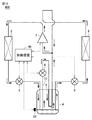
- FIG. 1 is a functional block diagram showing the configuration of the refrigeration cycle apparatus 100 according to the first embodiment.
- the refrigeration cycle apparatus 100 includes a compressor 1, a condenser 2 (first heat exchanger), an expansion valve 3 (first expansion valve), a refrigerant container 4, and an expansion valve 5. (Second expansion valve), evaporator 6 (second heat exchanger), pipe 71 (specific flow path), expansion valve 8 (third expansion valve), and internal heat exchanger 9 (third heat exchange) Device) and the control device 10.
- the refrigerant circulates in the order of the compressor 1, the condenser 2, the expansion valve 3, the refrigerant container 4, the expansion valve 5, and the evaporator 6.
- the refrigerant container 4 receives the refrigerant from the expansion valve 3 and stores the liquid refrigerant at the bottom.
- the pipe 71 communicates the expansion valve 8 and the refrigerant container 4.
- the internal heat exchanger 9 is connected between the expansion valve 8 and the suction port of the compressor 1 and is disposed in the refrigerant container 4.
- the control device 10 controls the amount of refrigerant discharged from the compressor 1 per unit time by controlling the drive frequency of the compressor 1.
- the control device 10 adjusts the opening degree of the expansion valves 3, 5, 8.
- FIG. 2 is a diagram showing a flow of processing of the expansion valve control performed by the control device 10 of FIG.
- the process shown in FIG. 2 is called by a main routine (not shown) that performs integrated control of the refrigeration cycle apparatus 100.
- the step is simply referred to as S.
- the control device 10 performs normal control on the expansion valves 3, 5, and 8 in S100, and advances the process to S200.
- the normal control includes, for example, superheat control that maintains the superheat of the refrigerant flowing out of the evaporator 6 within a certain range.
- the control device 10 performs a refrigerant amount adjustment process for adjusting the refrigerant amount in the refrigerant container 4, and then returns the process to the main routine.
- the refrigeration cycle apparatus 100 when the amount of refrigerant in the refrigerant container 4 decreases and wet steam flows out from the refrigerant container 4, the amount of refrigerant on the low pressure side (portion from the expansion valve 5 to the suction port of the compressor 1) decreases. As a result, the pressure on the low-pressure side of the refrigeration cycle apparatus 100 decreases. Therefore, the differential pressure between the pressure on the high pressure side of the refrigeration cycle apparatus 100 (the portion from the discharge port of the compressor 1 to the expansion valve 3) and the pressure on the low pressure side increases, and the efficiency of the refrigeration cycle apparatus 100 can be reduced.
- the opening of the expansion valve 5 When the opening of the expansion valve 5 is increased in order to increase the amount of refrigerant on the low pressure side by increasing the amount of refrigerant circulating in the refrigeration cycle apparatus 100 (circulating refrigerant amount), after the opening degree is fully opened, By controlling the opening degree of the expansion valve 5, the amount of refrigerant per unit time flowing out from the refrigerant container 4 to the expansion valve 5 cannot be increased. In such a case, the efficiency of the refrigeration cycle apparatus 100 cannot be suppressed by controlling the opening degree of the expansion valve 5. Further, when the opening degree of the expansion valve 5 is fully open, it is almost impossible to increase the amount of refrigerant flowing out of the refrigerant container 4, and therefore the decrease in the amount of refrigerant in the refrigerant container 4 is almost stopped.
- the opening amount of the expansion valve 8 is increased to increase the amount of refrigerant per unit time passing through the pipe 71. Since the amount of refrigerant flowing out from the refrigerant container 4 to the expansion valve 8 increases, the amount of refrigerant is added to the amount of refrigerant sucked into the compressor 1. As a result, the amount of circulating refrigerant increases, and a decrease in efficiency of the refrigeration cycle apparatus 100 can be suppressed.
- the opening degree of the expansion valve 5 is greater than or equal to the reference opening degree (for example, fully open). It is determined based on whether or not the condition is satisfied.
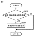
- FIG. 3 is a flowchart showing a specific process flow of the refrigerant quantity adjustment process (S200) of FIG.
- the control device 10 determines in S ⁇ b> 211 whether or not the opening degree of the expansion valve 5 is greater than or equal to the reference opening degree.
- the control device 10 increases the opening degree of the expansion valve 8 by a certain amount and returns the process to the main routine in S212.
- the opening degree of expansion valve 5 is less than the reference opening degree (NO in S211)
- control device 10 returns the process to the main routine.
- the fall of the efficiency of a refrigerating cycle apparatus can be controlled.
- Embodiment 2 FIG. In Embodiment 1, the structure which increases the opening amount of a 3rd expansion valve and increases the refrigerant
- FIG. 4 is a functional block diagram showing the configuration of the refrigeration cycle apparatus 200 according to the second embodiment.
- the configuration of the refrigeration cycle apparatus 200 in FIG. 4 is a configuration in which an opening / closing unit 80 is added to the configuration of the refrigeration cycle apparatus 100 in FIG. Since the configuration other than these is the same, the description will not be repeated.
- FIGS. 1 and 3 of the first embodiment are replaced with FIGS. 4 and 5, respectively.
- the opening / closing part 80 is connected between the pipe 71 and the suction port of the compressor 1.
- the control device 20 switches between opening and closing of the opening / closing unit 80.
- the opening / closing part 80 is opened, the refrigerant flowing into the pipe 71 is bypassed to the suction port of the compressor 1 via the opening / closing part 80.
- the expansion valve 8 can be downsized. By reducing the size of the expansion valve 8, the opening degree of the expansion valve 8 can be controlled in accordance with a relatively small resolution, so that the controllability of the expansion valve 8 can be improved.
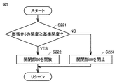
- FIG. 5 is a flowchart showing the flow of the refrigerant amount adjustment process performed by the control device 20 of FIG.
- the control device 20 determines whether or not the opening degree of the expansion valve 5 is greater than or equal to the reference opening degree in S ⁇ b> 221.
- the control device 20 opens the opening / closing part 80 and returns the process to the main routine in S222.
- the control device 20 closes the opening / closing part 80 and returns the process to the main routine in S223.
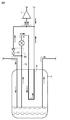
- FIG. 6 is a diagram illustrating an example of the configuration of the opening / closing unit 80 of FIG.
- the opening / closing part 80 includes an opening / closing valve 81.
- the on-off valve 81 is connected between the pipe 71 and the suction port of the compressor 1.
- the control device 20 opens the on-off valve 81 in S222 of FIG. 5 and closes the on-off valve 81 in S223.
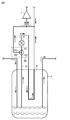
- FIG. 7 is a diagram showing another example of the configuration of the opening / closing unit 80 of FIG.
- the opening / closing part 80 includes a three-way valve 82.
- the three-way valve 82 has ports P1 to P3 that communicate with each other.
- the port P1 communicates with the expansion valve 8.
- the port P2 communicates with the refrigerant container 4.
- the port P3 communicates with the suction port of the compressor 1. Ports P1 and P2 are open.
- the port P3 is switched between opening and closing.
- the control device 20 opens the port P3 in S222 of FIG. 5, and closes the port P3 in S223.
- Embodiment 3 FIG.
- the configuration has been described in which the decrease in the efficiency of the refrigeration cycle apparatus due to the decrease in the amount of refrigerant in the refrigerant container and the outflow of wet steam from the refrigerant container has been described.
- the third embodiment a configuration that suppresses a decrease in efficiency of the refrigeration cycle apparatus due to an increase in the amount of refrigerant in the refrigerant container and a decrease in heat exchange efficiency of the third heat exchanger will be described.
- FIG. 8 is a functional block diagram showing the configuration of the refrigeration cycle apparatus 300 according to the third embodiment.
- the configuration of the refrigeration cycle apparatus 300 is a configuration in which a pressure sensor 91 is added to the refrigeration cycle apparatus 100 of FIG. 1, and the control device 10 is replaced with the control device 30. Since the configuration other than these is the same, the description will not be repeated.
- FIGS. 1 and 3 of the first embodiment are replaced with FIGS. 8 and 9, respectively.
- the pressure sensor 91 detects the pressure of the refrigerant (condensation pressure) in the condenser 2 and outputs a detection signal representing the condensation pressure to the control device 30.
- the control device 30 uses the detection signal from the pressure sensor 91 to control the opening degree of the expansion valve 3 to adjust the amount of refrigerant in the refrigerant container 4.
- the liquid level of the liquid refrigerant stored in the refrigerant container 4 increases as the amount of refrigerant in the refrigerant container 4 increases.
- the internal heat exchanger 9 is immersed in the liquid refrigerant, and the heat exchange efficiency of the internal heat exchanger 9 decreases.
- the efficiency of the refrigeration cycle apparatus 300 can be reduced.
- the smaller the amount of refrigerant in the condenser 2 the more the refrigerant distribution in the refrigeration cycle apparatus 300 is biased toward the low pressure side, so the amount of refrigerant in the refrigerant container 4 is larger. . Further, the smaller the amount of refrigerant in the condenser 2, the smaller the condensation pressure. Therefore, the smaller the condensation pressure, the greater the amount of refrigerant in the refrigerant container 4.
- the refrigeration cycle apparatus 300 when the amount of refrigerant in the refrigerant container 4 is larger than the reference amount, the liquid level rises, and the heat exchange efficiency of the internal heat exchanger 9 decreases from a desired level.
- the opening degree of the expansion valve 8 is decreased by a certain amount. Since the amount of refrigerant per unit time flowing from the expansion valve 3 into the refrigerant container 4 decreases and the liquid level of the liquid refrigerant stored in the refrigerant container 4 decreases, the heat exchange efficiency of the internal heat exchanger 9 is reduced. The decrease can be suppressed. As a result, a decrease in efficiency of the refrigeration cycle apparatus 300 can be suppressed.
- the refrigerating-cycle apparatus 300 can be reduced in size.
- whether the condition that the amount of refrigerant in the refrigerant container 4 is larger than the reference amount (specific condition) is satisfied, or whether the condition that the condensation pressure is smaller than the reference pressure is satisfied. Determine by.
- FIG. 9 is a flowchart showing the flow of the refrigerant amount adjustment process performed by the control device 30 of FIG.
- the control device 30 determines whether or not the condensation pressure is smaller than the reference pressure in S231. If the condensing pressure is smaller than the reference pressure (YES in S231), control device 30 decreases the opening of expansion valve 3 by a certain amount in S232, and returns the process to the main routine. If the condensing pressure is equal to or higher than the reference pressure (NO in S231), control device 30 increases the opening of expansion valve 3 by a certain amount in S233, and returns the process to the main routine.
- the refrigeration cycle apparatus when the amount of refrigerant in the refrigerant container increases and the heat exchange efficiency of the third heat exchanger decreases from a desired level, A decrease in efficiency can be suppressed. Moreover, according to the refrigeration cycle apparatus according to Embodiment 3, the refrigeration cycle apparatus can be reduced in size.
- Embodiment 4 FIG.
- the case where the opening of the second expansion valve is used as an index indicating the amount of refrigerant in the refrigerant container 4 has been described
- the case where the condensation pressure is used has been described
- the case where the height of the liquid refrigerant in the refrigerant container 4 is used as an index indicating the amount of refrigerant in the refrigerant container 4 will be described.
- FIG. 10 is a functional block diagram showing the configuration of the refrigeration cycle apparatus 400 according to the fourth embodiment.
- the configuration of the refrigeration cycle apparatus 400 is a configuration in which a liquid level sensor 92 is added to the refrigeration cycle apparatus 100 of FIG. 1 and the control device 10 is replaced with the control device 40. Since the configuration other than these is the same, the description will not be repeated.
- FIGS. 1 and 3 in the first embodiment are replaced with FIGS. 10 and 12, respectively.
- the liquid level sensor 92 detects the liquid level of the liquid refrigerant in the refrigerant container 4, and outputs a detection signal indicating the liquid level to the control device 40.
- the control device 30 uses the detection signal from the liquid level sensor 92 to control the opening degree of the expansion valve 8 to adjust the amount of refrigerant in the refrigerant container 4.
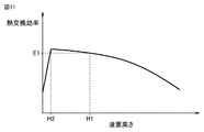
- FIG. 11 is a graph showing the relationship between the height of the liquid refrigerant stored in the refrigerant container 4 and the heat exchange efficiency of the internal heat exchanger 9.
- the liquid level height H1 is the maximum value of the liquid level that can maintain the differential pressure between the high pressure side pressure and the low pressure side pressure at an appropriate level. For example, when the condensation pressure is greater than the reference pressure.
- the liquid level height H2 is smaller than the liquid level height H1, and is the liquid level height when the heat exchange efficiency of the internal heat exchanger 9 is maximized.
- the end of the pipe 71 in the refrigerant container 4 approaches the liquid level as the liquid level stored in the refrigerant container 4 increases, and the dryness of the refrigerant flowing into the pipe 71 is increased. Decreases.
- the liquid refrigerant flows into the pipe 71, and the heat exchange efficiency of the internal heat exchanger 9 increases as compared with the case where the wet steam flows into the pipe 71.
- the internal heat exchanger 9 is immersed in the liquid refrigerant, and the internal heat exchanger 9 The heat exchange efficiency is reduced.
- the refrigeration cycle apparatus 400 by controlling the opening of the expansion valve 8 so as to suppress the liquid level of the liquid refrigerant stored in the refrigerant container 4 from deviating from the range of H2 to H1. And the fall of the heat exchange efficiency of the internal heat exchanger 9 is suppressed. As a result, a decrease in efficiency of the refrigeration cycle apparatus 400 can be suppressed. Moreover, since the internal heat exchanger 9 can be reduced in size by suppressing the fall of heat exchange efficiency, the refrigerating-cycle apparatus 400 can be reduced in size.
- the change in the liquid level of the liquid refrigerant stored in the refrigerant container 4 is within a certain range, the vibration of the liquid refrigerant in the refrigerant container 4 is suppressed, and the noise of the refrigeration cycle apparatus 400 is suppressed. . As a result, user comfort can be improved.
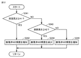
- FIG. 12 is a flowchart showing the flow of the refrigerant amount adjustment process performed by the control device 40 of FIG.
- the control device 40 determines in S241 whether or not the liquid level of the liquid refrigerant in the refrigerant container 4 is equal to or higher than the reference height H1 (first reference height).
- the control device 40 increases the opening of the expansion valve 8 by a certain amount in S242. Return to main routine.
- the controller 40 determines in S243 that the liquid level of the liquid refrigerant in the refrigerant container 4 is high. It is determined whether or not the height is equal to or higher than a reference height H2 (second reference height). When the liquid level of the liquid refrigerant in the refrigerant container 4 is equal to or higher than the reference height H2 (YES in S243), the control device 40 reduces the opening of the expansion valve 8 by a certain amount in S244. Return to main routine. When the liquid level of the liquid refrigerant in the refrigerant container 4 is less than the reference height H2 (NO in S243), the controller 40 increases the opening of the expansion valve 8 by a certain amount in S245 and performs processing. Return to main routine.
- the refrigeration cycle apparatus As described above, according to the refrigeration cycle apparatus according to Embodiment 4, a decrease in the efficiency of the refrigeration cycle apparatus can be suppressed. Moreover, according to the refrigeration cycle apparatus according to Embodiment 4, the refrigeration cycle apparatus can be reduced in size, and noise can be suppressed to improve user comfort.
- Embodiment 5 FIG.
- coolant amount per unit time which passes a specific flow path was demonstrated.
- the refrigerant per unit time passing through the specific flow path is bypassed from the specific flow path to the suction port of the compressor. A configuration for increasing the amount will be described.
- FIG. 13 is a functional block diagram showing the configuration of the refrigeration cycle apparatus 500 according to the fifth embodiment.
- the configuration of the refrigeration cycle apparatus 500 is a configuration in which an opening / closing part 80A is added to the refrigeration cycle apparatus 400 of FIG. Since the configuration other than these is the same, the description will not be repeated.
- FIGS. 10 and 12 of the fourth embodiment are replaced with FIGS. 13 and 14, respectively.
- the opening / closing part 80 ⁇ / b> A is connected between the pipe 71 and the suction port of the compressor 1.
- the control device 50 switches between opening and closing of the opening / closing part 80A.
- the specific configuration of the opening / closing part 80A is the same as that of the opening / closing part 80 of FIG. 6 or FIG.
- the expansion valve 8 can be downsized. By reducing the size of the expansion valve 8, the opening degree of the expansion valve 8 can be controlled in accordance with a relatively small resolution, so that the controllability of the expansion valve 8 can be improved.
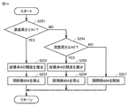
- FIG. 14 is a flowchart showing the flow of the refrigerant amount adjustment process performed by the control device 50 of FIG.
- the control device 50 determines whether or not the liquid level of the liquid refrigerant in the refrigerant container 4 is equal to or higher than the reference height H1.
- the controller 50 increases the opening of the expansion valve 8 by a certain amount in S252.
- the process proceeds to S253.
- the control device 50 closes the opening / closing part 80A and returns it to the main routine.
- the controller 50 determines in S254 that the liquid level of the liquid refrigerant in the refrigerant container 4 is high. It is determined whether the height is equal to or higher than the reference height H2.
- the controller 50 reduces the opening of the expansion valve 8 by a certain amount in S255. Proceed to S256.
- the control device 50 closes the opening / closing part 80A and returns the process to the main routine. If the liquid level of the liquid refrigerant in the refrigerant container 4 is less than the reference height H2 (NO in S254), the control device 50 opens the opening / closing part 80A and returns the process to the main routine in S257.
Landscapes
- Engineering & Computer Science (AREA)
- Physics & Mathematics (AREA)
- Mechanical Engineering (AREA)
- Thermal Sciences (AREA)
- General Engineering & Computer Science (AREA)
- Air Conditioning Control Device (AREA)
Abstract
Description
図1は、実施の形態1に係る冷凍サイクル装置100の構成を示す機能ブロック図である。図1に示されるように、冷凍サイクル装置100は、圧縮機1と、凝縮器2(第1熱交換器)と、膨張弁3(第1膨張弁)と、冷媒容器4と、膨張弁5(第2膨張弁)と、蒸発器6(第2熱交換器)と、配管71(特定流路)と、膨張弁8(第3膨張弁)と、内部熱交換器9(第3熱交換器)と、制御装置10とを備える。冷凍サイクル装置100において、冷媒は、圧縮機1、凝縮器2、膨張弁3、冷媒容器4、膨張弁5、および蒸発器6の順に循環する。
実施の形態1においては、第3膨張弁の開度を増加させて特定流路を通過する単位時間当たりの冷媒量を増加させる構成について説明した。実施の形態2においては、特定流路から圧縮機の吸入口へ冷媒をバイパスすることにより、特定流路を通過する単位時間当たりの冷媒量を増加させる構成について説明する。
実施の形態1,2においては、冷媒容器内の冷媒量が低下して冷媒容器から湿り蒸気が流出することによる冷凍サイクル装置の効率の低下を抑制する構成について説明した。実施の形態3においては、冷媒容器内の冷媒量が増加して第3熱交換器の熱交換効率が低下することによる冷凍サイクル装置の効率の低下を抑制する構成について説明する。
冷媒容器4内の冷媒量を示す指標として、実施の形態1,2においては第2膨張弁の開度を用いる場合について説明し、実施の形態3においては凝縮圧力を用いる場合について説明した。実施の形態4においては、冷媒容器4内の冷媒量を示す指標として冷媒容器4内の液冷媒の液面の高さを用いる場合について説明する。
実施の形態4においては、第3膨張弁の開度を増加させて特定流路を通過する単位時間当たりの冷媒量を増加させる構成について説明した。実施の形態5においては、第3膨張弁の開度を増加させることに加えて、特定流路から圧縮機の吸入口へ冷媒をバイパスすることによって、特定流路を通過する単位時間当たりの冷媒量を増加させる構成について説明する。
Claims (11)
- 冷媒が、圧縮機、第1熱交換器、第1膨張弁、冷媒容器、第2膨張弁、および第2熱交換器の順に循環する冷凍サイクル装置であって、
第3膨張弁と、
前記第3膨張弁および前記冷媒容器を連通する特定流路とを備え、
前記第3膨張弁は、前記冷媒容器を介して前記圧縮機の吸入口に連通し、
特定条件が満たされている場合の前記特定流路を通過する単位時間当たりの冷媒量は、前記特定条件が満たされていない場合の前記特定流路を通過する単位時間当たりの冷媒量よりも多く、
前記特定条件は、前記冷媒容器内の冷媒量が基準量よりも少ないという条件である、冷凍サイクル装置。 - 前記特定条件は、前記第2膨張弁の開度が基準開度以上という条件を含む、請求項1に記載の冷凍サイクル装置。
- 前記特定条件は、前記冷媒容器に貯留された液体の前記冷媒の液面の高さが基準高さより低いという条件を含む、請求項1に記載の冷凍サイクル装置。
- 前記特定条件が満たされている場合の前記第3膨張弁の開度は、前記特定条件が満たされていない場合の前記第3膨張弁の開度よりも大きい、請求項1~3のいずれか1項に記載の冷凍サイクル装置。
- 前記特定流路と前記吸入口との間に接続された開閉部をさらに備え、
前記特定条件が満たされている場合、前記開閉部は開放され、前記特定条件が満たされていない場合、前記開閉部は閉止される、請求項1~3のいずれか1項に記載の冷凍サイクル装置。 - 前記第3膨張弁と前記吸入口との間に接続され、前記冷媒容器内に配置された第3熱交換器をさらに備える、請求項1~5のいずれか1項に記載の冷凍サイクル装置。
- 冷媒が、圧縮機、第1熱交換器、第1膨張弁、冷媒容器、第2膨張弁、および第2熱交換器の順に循環する冷凍サイクル装置であって、
第3膨張弁と、
前記第3膨張弁および前記冷媒容器を連通する特定流路と、
前記第3膨張弁および前記圧縮機の吸入口の間に接続され、前記冷媒容器内に配置された第3熱交換器とを備え、
特定条件が満たされている場合、前記冷媒容器に流入する冷媒量は、前記冷媒容器から流出する冷媒量よりも少なく、
前記特定条件は、前記冷媒容器内の冷媒量が基準量よりも多いという条件であり、
前記特定条件が満たされている場合の前記第3熱交換器の熱交換効率は、前記冷媒容器内の冷媒量が基準量である場合の前記熱交換効率よりも小さい、冷凍サイクル装置。 - 前記特定条件は、前記第1熱交換器の圧力が基準圧力よりも小さいという条件を含み、
前記特定条件が成立している場合の前記第1膨張弁の開度は、前記特定条件が成立していない場合の前記第1膨張弁の開度よりも小さい、請求項7に記載の冷凍サイクル装置。 - 前記特定条件は、前記冷媒容器に貯留された液体の冷媒の液面の高さが第1基準高さよりも高いという条件を含み、
前記特定条件が満たされている場合、または前記高さが第2基準高さよりも低い場合の前記特定流路を通過する単位時間当たりの冷媒量は、前記高さが前記第2基準高さよりも高く、かつ前記第1基準高さよりも低い場合の前記特定流路を通過する単位時間当たりの冷媒量よりも多く、
前記第2基準高さは、前記第1基準高さよりも低い、請求項7に記載の冷凍サイクル装置。 - 前記高さが前記第1基準高さより高い場合、または前記高さが前記第2基準高さよりも低い場合の前記第3膨張弁の開度は、前記高さが前記第2基準高さよりも高く、かつ前記第1基準高さよりも低い場合の前記第3膨張弁の開度よりも大きい、請求項9に記載の冷凍サイクル装置。
- 前記特定流路と前記吸入口との間に接続された開閉部をさらに備え、
前記高さが前記第1基準高さより高い場合の前記第3膨張弁の開度は、前記高さが前記第2基準高さよりも高く、かつ前記第1基準高さよりも低い場合の前記第3膨張弁の開度よりも大きく、
前記高さが前記第2基準高さより低い場合、前記開閉部は開放され、
前記高さが前記第2基準高さよりも高く、かつ前記第1基準高さよりも低い場合、前記開閉部は閉止される、請求項9に記載の冷凍サイクル装置。
Priority Applications (4)
| Application Number | Priority Date | Filing Date | Title |
|---|---|---|---|
| JP2020525064A JP6925528B2 (ja) | 2018-06-15 | 2018-06-15 | 冷凍サイクル装置 |
| CN201880094106.9A CN112219074B9 (zh) | 2018-06-15 | 2018-06-15 | 冷冻循环装置 |
| EP18922598.0A EP3809064A4 (en) | 2018-06-15 | 2018-06-15 | COOLING CYCLE DEVICE |
| PCT/JP2018/022956 WO2019239587A1 (ja) | 2018-06-15 | 2018-06-15 | 冷凍サイクル装置 |
Applications Claiming Priority (1)
| Application Number | Priority Date | Filing Date | Title |
|---|---|---|---|
| PCT/JP2018/022956 WO2019239587A1 (ja) | 2018-06-15 | 2018-06-15 | 冷凍サイクル装置 |
Publications (1)
| Publication Number | Publication Date |
|---|---|
| WO2019239587A1 true WO2019239587A1 (ja) | 2019-12-19 |
Family
ID=68841937
Family Applications (1)
| Application Number | Title | Priority Date | Filing Date |
|---|---|---|---|
| PCT/JP2018/022956 Ceased WO2019239587A1 (ja) | 2018-06-15 | 2018-06-15 | 冷凍サイクル装置 |
Country Status (4)
| Country | Link |
|---|---|
| EP (1) | EP3809064A4 (ja) |
| JP (1) | JP6925528B2 (ja) |
| CN (1) | CN112219074B9 (ja) |
| WO (1) | WO2019239587A1 (ja) |
Cited By (2)
| Publication number | Priority date | Publication date | Assignee | Title |
|---|---|---|---|---|
| CN112611121A (zh) * | 2020-12-23 | 2021-04-06 | 青岛海信日立空调系统有限公司 | 一种制冷系统和两级节流阀的控制方法 |
| US20230134655A1 (en) * | 2020-06-02 | 2023-05-04 | Mitsubishi Electric Corporation | Refrigeration cycle device |
Citations (4)
| Publication number | Priority date | Publication date | Assignee | Title |
|---|---|---|---|---|
| JPS5544178U (ja) * | 1978-09-18 | 1980-03-22 | ||
| US20090019878A1 (en) * | 2005-02-18 | 2009-01-22 | Gupte Neelkanth S | Refrigeration circuit with improved liquid/vapour receiver |
| US20130145791A1 (en) * | 2011-06-16 | 2013-06-13 | Hill Phoenix, Inc. | Refrigeration system |
| WO2015198475A1 (ja) * | 2014-06-27 | 2015-12-30 | 三菱電機株式会社 | 冷凍サイクル装置 |
Family Cites Families (5)
| Publication number | Priority date | Publication date | Assignee | Title |
|---|---|---|---|---|
| WO2011117924A1 (ja) * | 2010-03-25 | 2011-09-29 | 三菱電機株式会社 | 冷凍サイクル装置及びその運転方法 |
| CN103380334B (zh) * | 2011-02-22 | 2016-03-16 | 日立空调·家用电器株式会社 | 冷冻循环装置 |
| WO2013080244A1 (ja) * | 2011-11-29 | 2013-06-06 | 三菱電機株式会社 | 冷凍空調装置 |
| JP6091399B2 (ja) * | 2013-10-17 | 2017-03-08 | 三菱電機株式会社 | 空気調和装置 |
| KR102242777B1 (ko) * | 2014-03-20 | 2021-04-20 | 엘지전자 주식회사 | 공기조화기 |
-
2018
- 2018-06-15 WO PCT/JP2018/022956 patent/WO2019239587A1/ja not_active Ceased
- 2018-06-15 JP JP2020525064A patent/JP6925528B2/ja not_active Expired - Fee Related
- 2018-06-15 EP EP18922598.0A patent/EP3809064A4/en not_active Withdrawn
- 2018-06-15 CN CN201880094106.9A patent/CN112219074B9/zh not_active Expired - Fee Related
Patent Citations (5)
| Publication number | Priority date | Publication date | Assignee | Title |
|---|---|---|---|---|
| JPS5544178U (ja) * | 1978-09-18 | 1980-03-22 | ||
| US20090019878A1 (en) * | 2005-02-18 | 2009-01-22 | Gupte Neelkanth S | Refrigeration circuit with improved liquid/vapour receiver |
| US20130145791A1 (en) * | 2011-06-16 | 2013-06-13 | Hill Phoenix, Inc. | Refrigeration system |
| WO2015198475A1 (ja) * | 2014-06-27 | 2015-12-30 | 三菱電機株式会社 | 冷凍サイクル装置 |
| JP5865561B1 (ja) | 2014-06-27 | 2016-02-17 | 三菱電機株式会社 | 冷凍サイクル装置 |
Cited By (3)
| Publication number | Priority date | Publication date | Assignee | Title |
|---|---|---|---|---|
| US20230134655A1 (en) * | 2020-06-02 | 2023-05-04 | Mitsubishi Electric Corporation | Refrigeration cycle device |
| CN112611121A (zh) * | 2020-12-23 | 2021-04-06 | 青岛海信日立空调系统有限公司 | 一种制冷系统和两级节流阀的控制方法 |
| CN112611121B (zh) * | 2020-12-23 | 2023-09-05 | 青岛海信日立空调系统有限公司 | 一种制冷系统和两级节流阀的控制方法 |
Also Published As
| Publication number | Publication date |
|---|---|
| EP3809064A4 (en) | 2021-09-22 |
| JP6925528B2 (ja) | 2021-08-25 |
| CN112219074B (zh) | 2022-12-06 |
| CN112219074B9 (zh) | 2023-01-20 |
| JPWO2019239587A1 (ja) | 2021-03-11 |
| EP3809064A1 (en) | 2021-04-21 |
| CN112219074A (zh) | 2021-01-12 |
Similar Documents
| Publication | Publication Date | Title |
|---|---|---|
| JP2537314B2 (ja) | 冷凍サイクル装置 | |
| US9151522B2 (en) | Air conditioner and control method thereof | |
| JPH11193967A (ja) | 冷凍サイクル | |
| CN106574813B (zh) | 用于控制可变能力喷射器单元的方法 | |
| JP2011208860A (ja) | 空気調和機 | |
| JP7150148B2 (ja) | 室外ユニット、冷凍サイクル装置および冷凍機 | |
| JP6925528B2 (ja) | 冷凍サイクル装置 | |
| JPH11142001A (ja) | 空気調和機 | |
| JP2002228282A (ja) | 冷凍装置 | |
| JP2001311567A (ja) | 冷凍装置およびそれを用いた環境試験装置 | |
| US8221104B2 (en) | Screw compressor having a slide valve with hot gas bypass port | |
| CN110686428A (zh) | 冷媒循环系统、空调机组和冷媒循环系统的控制方法 | |
| JP2017190938A (ja) | 冷凍サイクル装置 | |
| JP4599190B2 (ja) | 流量調整装置及び空気調和装置 | |
| CN109539614B (zh) | 一种空调系统及其能量调节方法 | |
| CN112513542B (zh) | 用于基于预估流量来控制蒸气压缩系统的方法 | |
| CN114165909A (zh) | 空调系统、空调系统的控制方法和计算机可读存储介质 | |
| JPH0651756U (ja) | 冷却装置 | |
| JP2008533428A (ja) | 遷臨界蒸気圧縮システムの高圧側圧力調整 | |
| JPH07294021A (ja) | ヒートポンプ式冷房除湿装置 | |
| JP2009236430A (ja) | 圧縮式冷凍機及びその容量制御方法 | |
| JP2010014386A (ja) | 冷凍装置 | |
| EP1235043A1 (en) | Refrigerating device | |
| KR100696712B1 (ko) | 멀티 에어컨의 압축기 보호 시스템 및 방법 | |
| JP7284381B2 (ja) | 冷凍装置 |
Legal Events
| Date | Code | Title | Description |
|---|---|---|---|
| 121 | Ep: the epo has been informed by wipo that ep was designated in this application |
Ref document number: 18922598 Country of ref document: EP Kind code of ref document: A1 |
|
| ENP | Entry into the national phase |
Ref document number: 2020525064 Country of ref document: JP Kind code of ref document: A |
|
| NENP | Non-entry into the national phase |
Ref country code: DE |
|
| WWE | Wipo information: entry into national phase |
Ref document number: 2018922598 Country of ref document: EP |
|
| WWW | Wipo information: withdrawn in national office |
Ref document number: 2018922598 Country of ref document: EP |