WO2019240038A1 - 検知装置及び検知方法 - Google Patents
検知装置及び検知方法 Download PDFInfo
- Publication number
- WO2019240038A1 WO2019240038A1 PCT/JP2019/022738 JP2019022738W WO2019240038A1 WO 2019240038 A1 WO2019240038 A1 WO 2019240038A1 JP 2019022738 W JP2019022738 W JP 2019022738W WO 2019240038 A1 WO2019240038 A1 WO 2019240038A1
- Authority
- WO
- WIPO (PCT)
- Prior art keywords
- log
- host
- detection
- network
- generation model
- Prior art date
- Legal status (The legal status is an assumption and is not a legal conclusion. Google has not performed a legal analysis and makes no representation as to the accuracy of the status listed.)
- Ceased
Links
Images


Classifications
-
- G—PHYSICS
- G06—COMPUTING OR CALCULATING; COUNTING
- G06F—ELECTRIC DIGITAL DATA PROCESSING
- G06F21/00—Security arrangements for protecting computers, components thereof, programs or data against unauthorised activity
- G06F21/50—Monitoring users, programs or devices to maintain the integrity of platforms, e.g. of processors, firmware or operating systems
- G06F21/55—Detecting local intrusion or implementing counter-measures
- G06F21/552—Detecting local intrusion or implementing counter-measures involving long-term monitoring or reporting
-
- H—ELECTRICITY
- H04—ELECTRIC COMMUNICATION TECHNIQUE
- H04L—TRANSMISSION OF DIGITAL INFORMATION, e.g. TELEGRAPHIC COMMUNICATION
- H04L43/00—Arrangements for monitoring or testing data switching networks
- H04L43/04—Processing captured monitoring data, e.g. for logfile generation
-
- G—PHYSICS
- G06—COMPUTING OR CALCULATING; COUNTING
- G06F—ELECTRIC DIGITAL DATA PROCESSING
- G06F21/00—Security arrangements for protecting computers, components thereof, programs or data against unauthorised activity
- G06F21/50—Monitoring users, programs or devices to maintain the integrity of platforms, e.g. of processors, firmware or operating systems
- G06F21/55—Detecting local intrusion or implementing counter-measures
- G06F21/554—Detecting local intrusion or implementing counter-measures involving event detection and direct action
-
- G—PHYSICS
- G16—INFORMATION AND COMMUNICATION TECHNOLOGY [ICT] SPECIALLY ADAPTED FOR SPECIFIC APPLICATION FIELDS
- G16Y—INFORMATION AND COMMUNICATION TECHNOLOGY SPECIALLY ADAPTED FOR THE INTERNET OF THINGS [IoT]
- G16Y30/00—IoT infrastructure
- G16Y30/10—Security thereof
-
- G—PHYSICS
- G16—INFORMATION AND COMMUNICATION TECHNOLOGY [ICT] SPECIALLY ADAPTED FOR SPECIFIC APPLICATION FIELDS
- G16Y—INFORMATION AND COMMUNICATION TECHNOLOGY SPECIALLY ADAPTED FOR THE INTERNET OF THINGS [IoT]
- G16Y40/00—IoT characterised by the purpose of the information processing
- G16Y40/10—Detection; Monitoring
-
- H—ELECTRICITY
- H04—ELECTRIC COMMUNICATION TECHNIQUE
- H04L—TRANSMISSION OF DIGITAL INFORMATION, e.g. TELEGRAPHIC COMMUNICATION
- H04L63/00—Network architectures or network communication protocols for network security
- H04L63/14—Network architectures or network communication protocols for network security for detecting or protecting against malicious traffic
- H04L63/1408—Network architectures or network communication protocols for network security for detecting or protecting against malicious traffic by monitoring network traffic
-
- H—ELECTRICITY
- H04—ELECTRIC COMMUNICATION TECHNIQUE
- H04L—TRANSMISSION OF DIGITAL INFORMATION, e.g. TELEGRAPHIC COMMUNICATION
- H04L63/00—Network architectures or network communication protocols for network security
- H04L63/14—Network architectures or network communication protocols for network security for detecting or protecting against malicious traffic
- H04L63/1441—Countermeasures against malicious traffic
Definitions
- the present invention relates to a detection device and a detection method.
- IoT In recent years, IoT has begun to spread, and until now, all devices are working cooperatively via a network to create various values. On the other hand, it creates vulnerabilities that you do not expect when various devices are connected via a network. In addition, there is also a dawn of the popularization of IoT, and a large number of devices with insufficient security measures are connected to the network.
- the anomaly detector can be divided into a list type detector and a learning type detector.
- the list type detector is a type in which a person designs detection conditions according to each IoT device.
- a learning type detector is a type that learns detection conditions from data.
- the learning type Since there are many types of IoT devices, the learning type is considered to become the mainstream. Furthermore, there are two types of learning-type detection methods: one that learns the normal state and detects an abnormality from a deviation from the normal state, and another type that learns the abnormal state and uses the proximity to the abnormal state to detect the abnormality. There is a thing.
- an anomaly detection type detection method using a detection model that learns a log of a normal state network to which an IoT device is connected is known as a detection method that detects an abnormality with a deviation from a normal state.
- an anomaly detection type detection method for learning a network log is effective in detecting anomalies due to a DoS attack or Arp spoofing, but may not be able to detect anomalies due to ransomware. This is because an abnormality caused by ransomware is less likely to appear as an abnormality on the network side and more likely to appear as an abnormality on the host side.
- the detection method for learning the host log log is effective for detecting anomalies by ransomware, but may not be effective for detecting anomalies by DoS attack or Arp spoofing.
- an abnormality of the IoT device can be detected with high accuracy.
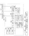
- FIG. 1 is a diagram illustrating an example of a configuration of a detection system according to the first embodiment.
- FIG. 2 is a diagram illustrating an example of the configuration of the detection device according to the first embodiment.
- FIG. 3 is a diagram for explaining the VAE.
- FIG. 4 is a diagram illustrating an example of a generation model according to the first embodiment.
- FIG. 5 is a diagram illustrating an example of a generation model according to the first embodiment.
- FIG. 6 is a diagram for explaining a method of aligning the granularity according to the first embodiment.
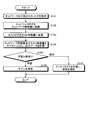
- FIG. 7 is a flowchart showing the flow of processing of the detection apparatus according to the first embodiment.
- FIG. 8 is a diagram for explaining the effect of the first embodiment.
- FIG. 9 is a diagram for explaining the effect of the first embodiment.
- FIG. 10 is a diagram for explaining the effect of the first embodiment.
- FIG. 11 is a diagram for explaining the effect of the first embodiment.
- FIG. 12 is a diagram illustrating an example
- FIG. 1 is a diagram illustrating an example of a configuration of a detection system according to the first embodiment.
- the detection system 1 includes a detection device 10, a gateway 20, and a device 30, and the gateway 20 is connected to an external network 40.
- the detection apparatus 10 acquires a log of communication between the device 30 and the external network 40 and passing through the gateway 20. For example, the detection apparatus 10 acquires the host log of the device 30. In addition, the detection device 10 detects an abnormality of the device 30 using the generation model learned using the acquired log.
- the device 30 is an IoT device such as a monitoring camera or a wearable device.
- the detection device 10 acquires a network log and a host log when the resolution of the monitoring camera is changed.
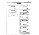
- FIG. 2 is a diagram illustrating an example of the configuration of the detection device according to the first embodiment.
- the detection device 10 includes an input / output unit 11, a communication unit 12, a storage unit 13, and a control unit 14.
- the detection apparatus 10 performs detection and learning using VAE (Variational Autoencoder). VAE will be described with reference to FIG. FIG. 3 is a diagram for explaining the VAE.
- VAE Vehicle Autoencoder
- the generation model of VAE is an auto encoder.
- the VAE generates a latent variable p (z) represented by a random variable by the encoder q ⁇ (z
- z) all assume distributions. Further, since the encoder q ⁇ (z
- the objective function is maximized by using the variation lower limit part obtained by subtracting the regularization term representing the constraint of p (z) by KL diversity from the reconstruction error term of logp (x).
- the detection device 10 of the present embodiment performs multimodal learning when learning the generation model.
- Multimodal learning is learning using data of different domains such as network logs and host logs. Note that learning using data of one domain is called single-modal learning.
- FIG. 4 is a diagram illustrating an example of a generation model according to the first embodiment.
- the detection apparatus 10 can input both learning data based on the network log and learning data based on the host log to the generation model.
- the detection apparatus 10 inputs a feature amount based on the network log to the layer 201a, and obtains data having an abstract meaning.
- the detection device 10 inputs a feature amount based on the host log to the layer 201b, and obtains data having an abstract meaning.
- the detection device 10 when a feature value is input to the layer 201a, the detection device 10 outputs output data via the layer 205a. On the other hand, when a feature amount is input to the layer 201b, the detection device 10 outputs output data via the layer 205b.
- the generation model feature values obtained from data in different domains are input to the layer corresponding to each domain, data output from the layer is merged in the intermediate layer, and data output from the intermediate layer Is provided with a neural network that branches to a layer corresponding to each domain in a layer before the output layer.
- the layer 201a, the layer 201b, the layer 205a, and the layer 205b may each be a plurality of layers.
- the layer 201a and the layer 201b may be referred to as an abstraction layer.
- the layer 205a and the layer 205b may be referred to as a materialized layer.
- the latent variable z is calculated as x ⁇ z ⁇ x.
- the latent variable z can be calculated using the abstracted data regardless of the domain of the data from which the input feature quantity x is based.
- the network log can obtain the feature quantity related to the number and size of packets
- the feature quantity related to the usage amount of the CPU (Central Processing Unit) and memory may not be obtained.
- a feature amount related to the usage amount of the CPU, memory, and the like is obtained, but a feature amount related to the number and size of packets may not be obtained. In this way, different feature amounts are obtained from data of different domains.
- each feature value is converted into data with abstract meanings such as “degree of rarity” and “degree of dispersion” by the abstraction layer, the feature values obtained from data in different domains are the same. It becomes possible to evaluate by the standard.
- the abstract meaning may be anything that can be interpreted in the generation model, and does not have to be something that can be expressed in a language as in the above example.
- the generation model of this embodiment is designed so that the number of dimensions of the abstraction layer and the materialization layer between the domains is as much as possible. Furthermore, the detection apparatus 10 adjusts the number of dimensions of the input feature value according to the generation model.
- FIG. 5 is a diagram illustrating an example of a generation model according to the first embodiment.
- the feature amount based on the network log is input, whereas the feature amount based on the host log is not input.
- the input / output unit 11 accepts data input from the user.
- the input / output unit 11 includes, for example, an input device such as a mouse and a keyboard, and a display device such as a display and a touch panel.
- the communication unit 12 performs data communication with other devices via a network.
- the communication unit 12 is a NIC (Network Interface Card).
- the communication unit 12 performs data communication with the gateway 20, for example.
- the storage unit 13 is a storage device such as an HDD (Hard Disk Drive), an SSD (Solid State Drive), or an optical disk.
- the storage unit 13 may be a semiconductor memory capable of rewriting data such as a RAM (Random Access Memory), a flash memory, and a NVSRAM (Non Volatile Static Random Access Memory).
- the storage unit 13 stores an OS (Operating System) executed by the detection apparatus 10 and various programs. Furthermore, the storage unit 13 stores various information used in executing the program.
- the storage unit 13 includes a model DB 131.
- the model DB 131 stores learned generation model parameters and the like.
- the control unit 14 controls the entire detection device 10.
- the control unit 14 is, for example, an electronic circuit such as a CPU, GPU (Graphics Processing Unit), TPU (Tensor Processing Unit), MPU (Micro Processing Unit), ASIC (Application Specific Integrated Circuit), FPGA (Field Programmable Gate Array). Or the like.
- the control unit 14 has an internal memory for storing programs and control data defining various processing procedures, and executes each process using the internal memory.
- the control unit 14 functions as various processing units when various programs are operated.
- the control unit 14 includes an acquisition unit 141, a first conversion unit 142, a second conversion unit 143, a calculation unit 144, a learning unit 145, and a detection unit 146.
- the acquisition unit 141 acquires the network log and host log of the device 30.
- the acquisition unit 141 can acquire an ipfix format network log using YAF (Yet Another Flowmeter) (for example, see Non-Patent Document 4).
- the OS of the device 30 is Linux (registered trademark)
- the acquisition unit 141 includes directories such as “/ proc / diskstats”, “/ proc / loadavg”, “/ proc / meminfo”, and “/ proc / stat”. Information relating to the CPU, memory, and disk I / O existing in the server can be acquired as a host log.
- the first conversion unit 142 is a generation model that generates output data based on a plurality of latent variables represented by random variables, and is a network feature quantity that can be input to a multimodal generation model. Convert to The network feature amount is an example of a first feature amount.
- the first conversion unit 142 can convert the quantitative data included in the network log into a predetermined statistical amount of the quantitative data.
- the quantitative data included in the network log includes the number of communication bytes, the number of packets, the number of flows, the packet size, and the like.
- the statistics are average, maximum, minimum, coefficient of variation, rate, and the like.
- the first conversion unit 142 converts qualitative data included in the network log into a k-hot (where k is an integer of 1 or more) vector.
- the first conversion unit 142 can convert the ip address, the mac address, and the port src and dst included in the network log into a 1-hot vector.
- the first conversion unit 142 can convert the protocol included in the network log into a k-hot vector. For example, when k is 2 and the four protocols from 0 to 3 are included in the network log, the first conversion unit 142 sets the protocol to [1, 0. , 0, 1].
- Examples of network feature amounts are shown below. “Up” indicates a direction from the device 30 toward the external network 40. Further, “down” indicates a direction from the external network 40 toward the device 30.
- -Number of bytes for up and down-Number of packets for up and down-Number of flows for up and down-Average packet size for up and down-Maximum packet size for up and down-Minimum packet for up and down Size • Average of the average packet size for each of up and down • Variation coefficient for each of up and down (standard deviation of average packet size divided by average of average packet size) ⁇ Average flow rate of up and down (divide the number of flows by time) -Average packet rate of up and down (divide the number of packets by time) ⁇ Ip address, mac address, protocol k-hot vector
- the first conversion unit 142 can adjust the network feature amount to a predetermined number of dimensions.
- the second conversion unit 143 converts the host log into a host feature amount in a format that can be input to the generated model.
- the host feature amount is an example of a second feature amount.
- the second conversion unit 143 can convert data that accumulates over time into an increase amount per unit time.
- the second conversion unit 143 can perform scale adjustment using a logarithm or the like.
- the second conversion unit 143 performs scale adjustment by logarithm for the following items that can be acquired by Linux. ⁇ SectorsRead ⁇ TimeSpentReading ⁇ SectorsWritten ⁇ TimeSpentWriting ⁇ TimeSpentDoing_I_Os ⁇ WeightedTimeSpentDoing_I_Os
- the second conversion unit 143 converts the time-series accumulated data included in the host log into data for each unit time, and further normalizes the data related to resource usage by dividing it by the total resource amount. For example, the second conversion unit 143 divides a value related to the memory by Total Mmory and converts it to 1 or less. In addition, the second conversion unit 143 divides the number of processes being executed by the total number of processes and converts the number to 1 or less.
- the second conversion unit 143 converts the sum of all items by the value of each item and converts it to 1 or less for the following items regarding the CPU usage status. ⁇ Cpu_user ⁇ Cpu_Nine ⁇ Cpu_system ⁇ Cpu_Idle ⁇ Cpu_Iowait ⁇ Cpu_Irq ⁇ Cpu_Softirq
- FIG. 6 is a diagram for explaining a method of aligning the granularity according to the first embodiment.
- the second conversion unit 143 calculates at least one of the maximum, minimum, average, and variance of each element of the plurality of host logs.
- the plurality of host logs are converted into one host feature amount.
- the output interval of the network log is different depending on the output interface.
- the second conversion unit 143 has at least one of the maximum, minimum, average, and variance of each element of the two host logs. Is calculated and converted into one host feature amount.
- the second conversion unit 143 does not convert the host feature amount. In this case, only the network feature amount is input to the generation model.
- the calculation unit 144 inputs at least one of the network feature amount and the host feature amount into the generation model, and calculates output data. Output data corresponding to the input data is obtained by the processing of the calculation unit 144.
- the detection apparatus 10 performs subsequent processing based on the degree of similarity between the input data and the output data.
- the learning unit 145 learns the generation model so that the difference between the output data and each feature amount input to the generation model becomes small. Specifically, the learning unit 145 updates the parameter of p (z) so that logp (x) in FIG. 3 is optimized.
- the detection unit 146 detects an abnormality of the device 30 using the anomaly score calculated based on the output data. For example, the detection unit 146 can determine that an abnormality has occurred in the device 30 when the value of logp (x) in FIG. 3 is an anomaly score and the anomaly score exceeds a threshold value.
- FIG. 7 is a flowchart showing the flow of processing of the detection apparatus according to the first embodiment. As shown in FIG. 7, first, the detection apparatus 10 acquires the network log and host log of the device 30 (step S101).
- the detection apparatus 10 converts the network log into a network feature amount (step S102). Further, the detection apparatus 10 converts the host log into a host feature amount (step S103). Then, the detection device 10 inputs the network feature amount and the host feature amount into the model, and calculates output data (step S104).
- step S105 learning
- step S106 learning
- step S107 detecting
- the detection device 10 acquires the network log and host log of the device 30.
- the detection device 10 is a generation model that generates output data on the basis of a plurality of latent variables represented by random variables and converts the network log into a network feature amount that can be input to a multimodal generation model. Convert.
- the detection apparatus 10 converts the host log into a host feature amount in a format that can be input to the generation model.
- the detection apparatus 10 inputs at least one of the network feature amount and the host feature amount into the generation model, and calculates output data.
- the detection apparatus 10 detects an abnormality of the device 30 using the anomaly score calculated based on the output data.
- the detection apparatus 10 detects an abnormality using the feature amount converted from both the network log and the host log, the abnormality of the IoT device can be detected with high accuracy.
- the detection device 10 can detect both an abnormality caused by a DoS attack or Arp spoofing and an abnormality caused by ransomware.
- the detection device 10 can learn the generation model so that the difference between the output data and each feature amount input to the generation model becomes small.
- the detection apparatus 10 can further learn a model used for detection.
- the detection device 10 converts the quantitative data included in the network log into a predetermined statistic of the quantitative data, and converts the qualitative data included in the network log into k-hot (where k is an integer of 1 or more). Can be converted to a vector. Thereby, the detection apparatus 10 can adjust the number of dimensions of the feature amount.
- the detection device 10 converts time-series accumulated data included in the host log into data for each unit time, and further normalizes by dividing the data regarding the resource usage by the total resource amount. Thereby, the detection apparatus 10 can normalize data and can adjust the dimension number of a feature-value.
- the detection device 10 calculates at least one of the maximum, minimum, average, and variance of each element of the plurality of host logs.
- a plurality of host logs can be converted into one host feature amount.
- the detection apparatus 10 can align the granularity of the network feature value and the host feature value.
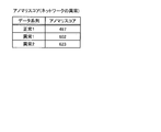
- FIG. 8 to FIG. 11 are diagrams for explaining the effect of the first embodiment.
- the device 30 is a small computer rasberry pi equipped with a video camera.
- the network log and the host log when the moving image was streamed using the device 30 were used as normal state data.
- FIG. 8 and FIG. 9 show the results when the network abnormality is simulated by changing the image quality of the moving image being streamed by the device 30.
- the image quality of the moving image is changed from high image quality to low image quality, and the anomaly score is calculated from the network log and the host log acquired at that time using the detection device 10, according to the change. Anomaly score increased.
- FIG. 10 and FIG. 11 show the results when the ransomware is simulated by executing file encryption during streaming by the device 30.
- the size of the file to be encrypted is increased from the state where the encryption is not performed, and the anomaly score is obtained from the network log and the host log obtained at that time using the detection device 10. As a result, the anomaly score increased as the size increased.
- the anomaly score calculated by the detection device 10 of the first embodiment increases in accordance with the abnormality that has occurred in the device 30. At this time, if an appropriate threshold value is set, the detection device 10 can detect an abnormality.
- each component of each illustrated device is functionally conceptual and does not necessarily need to be physically configured as illustrated.
- the specific form of distribution / integration of each device is not limited to the one shown in the figure, and all or a part of the distribution / integration is functionally or physically distributed in arbitrary units according to various loads or usage conditions. Can be integrated and configured.
- all or a part of each processing function performed in each device may be realized by a CPU and a program that is analyzed and executed by the CPU, or may be realized as hardware by wired logic.
- the detection apparatus 10 can be implemented by installing a detection program for executing the above detection as package software or online software on a desired computer.
- the information processing apparatus can function as the detection apparatus 10 by causing the information processing apparatus to execute the detection program.
- the information processing apparatus referred to here includes a desktop or notebook personal computer.
- the information processing apparatus includes mobile communication terminals such as smartphones, mobile phones and PHS (Personal Handyphone System), and slate terminals such as PDA (Personal Digital Assistant).
- the detection device 10 can also be implemented as a detection server device that uses a terminal device used by a user as a client and provides the client with the above-described detection-related services.
- the detection server device is implemented as a server device that provides a detection service that receives a network log and a host log and outputs a detection result.
- the detection server device may be implemented as a Web server, or may be implemented as a cloud that provides the above-described detection service by outsourcing.
- FIG. 12 is a diagram illustrating an example of a computer that executes a detection program.
- the computer 1000 includes a memory 1010 and a CPU 1020, for example.
- the computer 1000 also includes a hard disk drive interface 1030, a disk drive interface 1040, a serial port interface 1050, a video adapter 1060, and a network interface 1070. These units are connected by a bus 1080.
- the memory 1010 includes a ROM (Read Only Memory) 1011 and a RAM 1012.
- the ROM 1011 stores a boot program such as BIOS (Basic Input Output System).
- BIOS Basic Input Output System
- the hard disk drive interface 1030 is connected to the hard disk drive 1090.
- the disk drive interface 1040 is connected to the disk drive 1100.
- a removable storage medium such as a magnetic disk or an optical disk is inserted into the disk drive 1100.
- the serial port interface 1050 is connected to a mouse 1110 and a keyboard 1120, for example.
- the video adapter 1060 is connected to the display 1130, for example.
- the hard disk drive 1090 stores, for example, an OS 1091, an application program 1092, a program module 1093, and program data 1094. That is, a program that defines each process of the detection apparatus 10 is implemented as a program module 1093 in which a code executable by a computer is described.
- the program module 1093 is stored in the hard disk drive 1090, for example.
- a program module 1093 for executing processing similar to the functional configuration in the detection apparatus 10 is stored in the hard disk drive 1090.
- the hard disk drive 1090 may be replaced by an SSD.
- the setting data used in the processing of the above-described embodiment is stored as program data 1094 in, for example, the memory 1010 or the hard disk drive 1090. Then, the CPU 1020 reads the program module 1093 and the program data 1094 stored in the memory 1010 and the hard disk drive 1090 to the RAM 1012 and executes them as necessary.
- the program module 1093 and the program data 1094 are not limited to being stored in the hard disk drive 1090, but may be stored in, for example, a removable storage medium and read by the CPU 1020 via the disk drive 1100 or the like. Alternatively, the program module 1093 and the program data 1094 may be stored in another computer connected via a network (LAN (Local Area Network), WAN (Wide Area Network), etc.). Then, the program module 1093 and the program data 1094 may be read by the CPU 1020 from another computer via the network interface 1070.
- LAN Local Area Network
- WAN Wide Area Network
Landscapes
- Engineering & Computer Science (AREA)
- Computer Security & Cryptography (AREA)
- Computing Systems (AREA)
- Software Systems (AREA)
- Computer Hardware Design (AREA)
- General Engineering & Computer Science (AREA)
- Theoretical Computer Science (AREA)
- Signal Processing (AREA)
- Computer Networks & Wireless Communication (AREA)
- Physics & Mathematics (AREA)
- General Physics & Mathematics (AREA)
- Data Mining & Analysis (AREA)
- Debugging And Monitoring (AREA)
- Data Exchanges In Wide-Area Networks (AREA)
Abstract
Description
まず、図1を用いて、第1の実施形態に係る検知システムの構成について説明する。図1は、第1の実施形態に係る検知システムの構成の一例を示す図である。図1に示すように、検知システム1は、検知装置10、ゲートウェイ20、機器30を有し、ゲートウェイ20は外部ネットワーク40と接続されている。
・upとdownそれぞれのバイト数
・upとdownそれぞれのパケット数
・upとdownそれぞれのフロー数
・upとdownそれぞれの平均パケットサイズ
・upとdownそれぞれの最大パケットサイズ
・upとdownそれぞれの最小パケットサイズ
・upとdownそれぞれの平均パケットサイズの平均
・upとdownそれぞれの変動係数(平均パケットサイズの標準偏差を平均パケットサイズの平均で割ったもの)
・upとdownそれぞれの平均フローレート(フロー数を時間で割る)
・upとdownそれぞれの平均パケットレート(パケット数を時間で割る)
・ipアドレス、macアドレス、プロトコルのk-hotベクトル
・SectorsRead
・TimeSpentReading
・SectorsWritten
・TimeSpentWriting
・TimeSpentDoing_I_Os
・WeightedTimeSpentDoing_I_Os
・Cpu_user
・Cpu_Nine
・Cpu_system
・Cpu_Idle
・Cpu_Iowait
・Cpu_Irq
・Cpu_Softirq
図7を用いて検知装置10の処理について説明する。図7は、第1の実施形態に係る検知装置の処理の流れを示すフローチャートである。図7に示すように、まず、検知装置10は、機器30のネットワークログ及びホストログを取得する(ステップS101)。
第1の実施形態において、検知装置10は、機器30のネットワークログ及びホストログを取得する。また、検知装置10は、ネットワークログを、確率変数で表される複数の潜在変数を基に出力データを生成する生成モデルであって、マルチモーダルな生成モデルに入力可能な形式のネットワーク特徴量に変換する。また、検知装置10は、ホストログを、生成モデルに入力可能な形式のホスト特徴量に変換する。また、検知装置10は、ネットワーク特徴量及びホスト特徴量のうちの少なくとも一方を生成モデルに入力し、出力データを計算する。また、検知装置10は、出力データを基に計算したアノマリスコアを用いて、機器30の異常の検知を行う。このように、検知装置10は、ネットワークログ及びホストログの両方から変換した特徴量を使って異常の検知を行うため、IoT機器の異常を高い精度で検知することができる。例えば、検知装置10は、DoS攻撃やArp spoofingによる異常、及びランサムウェアによる異常の両方を検知することができる。
また、図示した各装置の各構成要素は機能概念的なものであり、必ずしも物理的に図示のように構成されていることを要しない。すなわち、各装置の分散・統合の具体的形態は図示のものに限られず、その全部又は一部を、各種の負荷や使用状況等に応じて、任意の単位で機能的又は物理的に分散・統合して構成することができる。さらに、各装置にて行われる各処理機能は、その全部又は任意の一部が、CPU及び当該CPUにて解析実行されるプログラムにて実現され、あるいは、ワイヤードロジックによるハードウェアとして実現され得る。
一実施形態として、検知装置10は、パッケージソフトウェアやオンラインソフトウェアとして上記の検知を実行する検知プログラムを所望のコンピュータにインストールさせることによって実装できる。例えば、上記の検知プログラムを情報処理装置に実行させることにより、情報処理装置を検知装置10として機能させることができる。ここで言う情報処理装置には、デスクトップ型又はノート型のパーソナルコンピュータが含まれる。また、その他にも、情報処理装置にはスマートフォン、携帯電話機やPHS(Personal Handyphone System)等の移動体通信端末、さらには、PDA(Personal Digital Assistant)等のスレート端末等がその範疇に含まれる。
11 入出力部
12 通信部
13 記憶部
14 制御部
20 ゲートウェイ
30 機器
40 外部ネットワーク
141 取得部
142 第1の変換部
143 第2の変換部
144 計算部
145 学習部
146 検知部
Claims (6)
- 機器のネットワークログ及びホストログを取得する取得部と、
前記ネットワークログを、確率変数で表される複数の潜在変数を基に出力データを生成する生成モデルであって、マルチモーダルな生成モデルに入力可能な形式の第1の特徴量に変換する第1の変換部と、
前記ホストログを、前記生成モデルに入力可能な形式の第2の特徴量に変換する第2の変換部と、
前記第1の特徴量及び前記第2の特徴量のうちの少なくとも一方を前記生成モデルに入力し、前記出力データを計算する計算部と、
前記出力データを基に計算したアノマリスコアを用いて、前記機器の異常の検知を行う検知部と、
を有することを特徴とする検知装置。 - 前記出力データと前記生成モデルに入力した各特徴量との差分が小さくなるように前記生成モデルの学習を行う学習部をさらに有することを特徴とする請求項1に記載の検知装置。
- 前記第1の変換部は、前記ネットワークログに含まれる量的データを前記量的データの所定の統計量に変換し、前記ネットワークログに含まれる質的データをk-hot(ただし、kは1以上の整数)ベクトルに変換することを特徴とする請求項1に記載の検知装置。
- 前記第2の変換部は、前記ホストログに含まれる時系列の累積データを単位時間ごとのデータに変換し、さらに、リソースの使用量に関するデータを全リソース量で割ることで正規化することを特徴とする請求項1に記載の検知装置。
- 前記第2の変換部は、
1つのネットワークログに複数のホストログが対応している場合、前記複数のホストログの各要素の最大、最小、平均及び分散のうちの少なくともいずれかを計算することで、前記複数のホストログを1つの前記第2の特徴量に変換することを特徴とする請求項1に記載の検知装置。 - コンピュータによって実行される検知方法であって、
機器からネットワークログ及びホストログを取得する取得工程と、
前記ネットワークログを、確率変数で表される複数の潜在変数を基に出力データを生成するマルチモーダルな生成モデルに入力可能な形式の第1の特徴量に変換する第1の変換工程と、
前記ホストログを、前記生成モデルに入力可能な形式の第2の特徴量に変換する第2の変換工程と、
を含むことを特徴とする検知方法。
Priority Applications (4)
| Application Number | Priority Date | Filing Date | Title |
|---|---|---|---|
| CN201980038762.1A CN112262387B (zh) | 2018-06-13 | 2019-06-07 | 检测装置和检测方法 |
| US16/973,433 US11563654B2 (en) | 2018-06-13 | 2019-06-07 | Detection device and detection method |
| AU2019287212A AU2019287212B2 (en) | 2018-06-13 | 2019-06-07 | Detection device and detection method |
| EP19820281.4A EP3816829B1 (en) | 2018-06-13 | 2019-06-07 | Detection device and detection method |
Applications Claiming Priority (2)
| Application Number | Priority Date | Filing Date | Title |
|---|---|---|---|
| JP2018113154A JP7014054B2 (ja) | 2018-06-13 | 2018-06-13 | 検知装置及び検知方法 |
| JP2018-113154 | 2018-06-13 |
Publications (1)
| Publication Number | Publication Date |
|---|---|
| WO2019240038A1 true WO2019240038A1 (ja) | 2019-12-19 |
Family
ID=68842801
Family Applications (1)
| Application Number | Title | Priority Date | Filing Date |
|---|---|---|---|
| PCT/JP2019/022738 Ceased WO2019240038A1 (ja) | 2018-06-13 | 2019-06-07 | 検知装置及び検知方法 |
Country Status (6)
| Country | Link |
|---|---|
| US (1) | US11563654B2 (ja) |
| EP (1) | EP3816829B1 (ja) |
| JP (1) | JP7014054B2 (ja) |
| CN (1) | CN112262387B (ja) |
| AU (1) | AU2019287212B2 (ja) |
| WO (1) | WO2019240038A1 (ja) |
Families Citing this family (7)
| Publication number | Priority date | Publication date | Assignee | Title |
|---|---|---|---|---|
| US11928208B2 (en) * | 2018-10-02 | 2024-03-12 | Nippon Telegraph And Telephone Corporation | Calculation device, calculation method, and calculation program |
| US11750629B2 (en) * | 2019-11-21 | 2023-09-05 | Hewlett Packard Enterprise Development Lp | Classification based anomaly detection |
| JP7234173B2 (ja) * | 2020-03-06 | 2023-03-07 | Kddi株式会社 | モデル学習装置、モデル学習方法及びコンピュータプログラム |
| JP7487769B2 (ja) * | 2020-03-27 | 2024-05-21 | 日本電気株式会社 | 異常アクセス予測システム、異常アクセス予測方法および異常アクセス予測プログラム |
| US12511533B2 (en) * | 2021-07-09 | 2025-12-30 | Robert Bosch Gmbh | Anomalous region detection with local neural transformations |
| JP2023173987A (ja) * | 2022-05-27 | 2023-12-07 | 三菱電機株式会社 | 学習装置、監視システム、学習方法およびプログラム |
| US20250094473A1 (en) * | 2023-09-19 | 2025-03-20 | Palantir Technologies Inc. | Systems and methods for windowed summarizations of event logs |
Citations (2)
| Publication number | Priority date | Publication date | Assignee | Title |
|---|---|---|---|---|
| JP2018025936A (ja) * | 2016-08-09 | 2018-02-15 | オークマ株式会社 | 工作機械 |
| JP2018073258A (ja) * | 2016-11-02 | 2018-05-10 | 日本電信電話株式会社 | 検知装置、検知方法および検知プログラム |
Family Cites Families (9)
| Publication number | Priority date | Publication date | Assignee | Title |
|---|---|---|---|---|
| KR100434205B1 (ko) * | 2001-07-26 | 2004-06-04 | 펜타시큐리티시스템 주식회사 | 다단계 침입 탐지 엔진 |
| KR20160095856A (ko) * | 2015-02-04 | 2016-08-12 | 한국전자통신연구원 | 새로운 공격 유형의 자동 탐지 및 공격 유형 모델 갱신을 통한 지능형 침입 탐지 시스템 및 방법 |
| US9876813B2 (en) * | 2015-02-11 | 2018-01-23 | Qualys, Inc. | System and method for web-based log analysis |
| CN106302350B (zh) * | 2015-06-01 | 2019-09-03 | 阿里巴巴集团控股有限公司 | Url监测方法、装置及设备 |
| US10154053B2 (en) * | 2015-06-04 | 2018-12-11 | Cisco Technology, Inc. | Method and apparatus for grouping features into bins with selected bin boundaries for use in anomaly detection |
| CN105468995A (zh) * | 2015-12-15 | 2016-04-06 | 吉林大学 | 以Oracle为核心的基于数据挖掘入侵检测系统 |
| JP6401424B2 (ja) * | 2016-06-23 | 2018-10-10 | 日本電信電話株式会社 | ログ分析装置、ログ分析方法およびログ分析プログラム |
| US10885165B2 (en) * | 2017-05-17 | 2021-01-05 | Forescout Technologies, Inc. | Account monitoring |
| CN107798235B (zh) * | 2017-10-30 | 2020-01-10 | 清华大学 | 基于one-hot编码机制的无监督异常访问检测方法及装置 |
-
2018
- 2018-06-13 JP JP2018113154A patent/JP7014054B2/ja active Active
-
2019
- 2019-06-07 WO PCT/JP2019/022738 patent/WO2019240038A1/ja not_active Ceased
- 2019-06-07 US US16/973,433 patent/US11563654B2/en active Active
- 2019-06-07 AU AU2019287212A patent/AU2019287212B2/en active Active
- 2019-06-07 EP EP19820281.4A patent/EP3816829B1/en active Active
- 2019-06-07 CN CN201980038762.1A patent/CN112262387B/zh active Active
Patent Citations (2)
| Publication number | Priority date | Publication date | Assignee | Title |
|---|---|---|---|---|
| JP2018025936A (ja) * | 2016-08-09 | 2018-02-15 | オークマ株式会社 | 工作機械 |
| JP2018073258A (ja) * | 2016-11-02 | 2018-05-10 | 日本電信電話株式会社 | 検知装置、検知方法および検知プログラム |
Non-Patent Citations (6)
| Title |
|---|
| CERT NETSA SECURITY SUITE, YAF, 4 June 2018 (2018-06-04), Retrieved from the Internet <URL:https://tools.netsa.cert.org/yaf/index.html>> |
| DIEDERIK P. KINGMAMAX WELLING, AUTO-ENCODING VARIATIONAL BAYES, 4 June 2018 (2018-06-04), Retrieved from the Internet <URL:https://arxiv.org/pdf/1312.6114.pdf>> |
| JINWON ANSUNGZOON CHO, VARIATIONAL AUTOENCODER BASED ANOMALY DETECTION USING RECONSTRUCTION PROBABILITY, 4 June 2018 (2018-06-04), Retrieved from the Internet <URL:http://dm.snu.ac.kr/static/docs/TR/SNUDM-TR-2015-03.pdf>> |
| KEITA KIKUCHI, MITSUHIRO MATSUNAGA, HISASHI KASHIMA: "Outlier Detection Model on the Failure Detection for IoT Home Appliance", DOCUMENTS OF RESEARCH GROUP OF THE INSTITUTE OF ELECTRICAL ENGINEERING OF JAPAN, vol. IS-18-013, 22 March 2018 (2018-03-22), pages 61 - 65, XP009524661 * |
| MASAHIRO SUZUKIKOTARO NAKAYAMAYUTAKA MATSUO, JOINT MULTIMODAL LEARNING WITH DEEP GENERATIVE MODELS, 4 June 2018 (2018-06-04), Retrieved from the Internet <URL:https://arxiv.org/pdf/1611.01891.pdf>> |
| See also references of EP3816829A4 |
Also Published As
| Publication number | Publication date |
|---|---|
| AU2019287212B2 (en) | 2022-07-14 |
| EP3816829B1 (en) | 2023-04-12 |
| EP3816829A1 (en) | 2021-05-05 |
| US20210250260A1 (en) | 2021-08-12 |
| EP3816829A4 (en) | 2022-01-19 |
| JP2019215757A (ja) | 2019-12-19 |
| JP7014054B2 (ja) | 2022-02-01 |
| CN112262387A (zh) | 2021-01-22 |
| CN112262387B (zh) | 2024-08-09 |
| US11563654B2 (en) | 2023-01-24 |
| AU2019287212A1 (en) | 2021-01-07 |
Similar Documents
| Publication | Publication Date | Title |
|---|---|---|
| JP7014054B2 (ja) | 検知装置及び検知方法 | |
| US12531890B2 (en) | Real-time cybersecurity status system with event ticker | |
| US11070582B1 (en) | Cloud-based cybersecurity portal with vulnerability data management | |
| CN110213227B (zh) | 一种网络数据流检测方法及装置 | |
| RU2697955C2 (ru) | Система и способ обучения модели обнаружения вредоносных контейнеров | |
| US10938783B2 (en) | Cluster-based determination of signatures for detection of anomalous data traffic | |
| US20230319099A1 (en) | Fuzz testing of machine learning models to detect malicious activity on a computer | |
| WO2019245006A1 (ja) | 検知装置及び検知方法 | |
| Kiran et al. | Detecting anomalous packets in network transfers: investigations using PCA, autoencoder and isolation forest in TCP | |
| JP7176635B2 (ja) | グラフ解析装置、グラフ解析方法及びグラフ解析プログラム | |
| CN116113960B (zh) | 学习装置、学习方法以及记录介质 | |
| JP6767312B2 (ja) | 検知システム、検知方法及び検知プログラム | |
| JP2019103069A (ja) | 特定システム、特定方法及び特定プログラム | |
| EP4105802A1 (en) | Method, computer-readable medium and system to detect malicious software in hierarchically structured files | |
| JP7444270B2 (ja) | 判定装置、判定方法及び判定プログラム | |
| JP7448022B2 (ja) | 検知装置、検知方法及び検知プログラム | |
| US11755398B2 (en) | Time series clustering to troubleshoot device problems based on missed and delayed data | |
| US20230237150A1 (en) | Structured data flow identification for proactive issue detection | |
| WO2020234977A1 (ja) | 情報処理装置、作成方法および作成プログラム | |
| JP7176630B2 (ja) | 検知装置、検知方法および検知プログラム | |
| JP2019101781A (ja) | 検知システム、学習方法及び学習プログラム | |
| WO2024247003A1 (ja) | 推定装置、推定方法及び推定プログラム | |
| HK40086407A (en) | Method, computer-readable medium and system to detect malicious software in hierarchically structured files | |
| WO2025104880A1 (ja) | 検知装置及び検知方法 |
Legal Events
| Date | Code | Title | Description |
|---|---|---|---|
| 121 | Ep: the epo has been informed by wipo that ep was designated in this application |
Ref document number: 19820281 Country of ref document: EP Kind code of ref document: A1 |
|
| ENP | Entry into the national phase |
Ref document number: 2019820281 Country of ref document: EP Effective date: 20201208 |
|
| NENP | Non-entry into the national phase |
Ref country code: DE |
|
| ENP | Entry into the national phase |
Ref document number: 2019287212 Country of ref document: AU Date of ref document: 20190607 Kind code of ref document: A |