WO2019242732A1 - 配置测量间隔的方法及设备 - Google Patents
配置测量间隔的方法及设备 Download PDFInfo
- Publication number
- WO2019242732A1 WO2019242732A1 PCT/CN2019/092281 CN2019092281W WO2019242732A1 WO 2019242732 A1 WO2019242732 A1 WO 2019242732A1 CN 2019092281 W CN2019092281 W CN 2019092281W WO 2019242732 A1 WO2019242732 A1 WO 2019242732A1
- Authority
- WO
- WIPO (PCT)
- Prior art keywords
- configure
- node
- terminal
- utran
- measurement
- Prior art date
- Legal status (The legal status is an assumption and is not a legal conclusion. Google has not performed a legal analysis and makes no representation as to the accuracy of the status listed.)
- Ceased
Links
Images


Classifications
-
- H—ELECTRICITY
- H04—ELECTRIC COMMUNICATION TECHNIQUE
- H04W—WIRELESS COMMUNICATION NETWORKS
- H04W24/00—Supervisory, monitoring or testing arrangements
- H04W24/10—Scheduling measurement reports ; Arrangements for measurement reports
-
- H—ELECTRICITY
- H04—ELECTRIC COMMUNICATION TECHNIQUE
- H04L—TRANSMISSION OF DIGITAL INFORMATION, e.g. TELEGRAPHIC COMMUNICATION
- H04L41/00—Arrangements for maintenance, administration or management of data switching networks, e.g. of packet switching networks
- H04L41/08—Configuration management of networks or network elements
- H04L41/0803—Configuration setting
-
- H—ELECTRICITY
- H04—ELECTRIC COMMUNICATION TECHNIQUE
- H04W—WIRELESS COMMUNICATION NETWORKS
- H04W24/00—Supervisory, monitoring or testing arrangements
- H04W24/02—Arrangements for optimising operational condition
-
- H—ELECTRICITY
- H04—ELECTRIC COMMUNICATION TECHNIQUE
- H04W—WIRELESS COMMUNICATION NETWORKS
- H04W24/00—Supervisory, monitoring or testing arrangements
- H04W24/08—Testing, supervising or monitoring using real traffic
-
- H—ELECTRICITY
- H04—ELECTRIC COMMUNICATION TECHNIQUE
- H04W—WIRELESS COMMUNICATION NETWORKS
- H04W76/00—Connection management
- H04W76/10—Connection setup
- H04W76/15—Setup of multiple wireless link connections
-
- H—ELECTRICITY
- H04—ELECTRIC COMMUNICATION TECHNIQUE
- H04W—WIRELESS COMMUNICATION NETWORKS
- H04W84/00—Network topologies
- H04W84/18—Self-organising networks, e.g. ad-hoc networks or sensor networks
-
- H—ELECTRICITY
- H04—ELECTRIC COMMUNICATION TECHNIQUE
- H04W—WIRELESS COMMUNICATION NETWORKS
- H04W88/00—Devices specially adapted for wireless communication networks, e.g. terminals, base stations or access point devices
- H04W88/02—Terminal devices
- H04W88/06—Terminal devices adapted for operation in multiple networks or having at least two operational modes, e.g. multi-mode terminals
Definitions
- the SN For the gap configuration of the UE, the SN needs to report the FR1 and FR2 frequency point information to be measured to the MN, so that the MN configures an appropriate gap pattern.
- the primary node receives first instruction information sent by the secondary node, where the first instruction information is used to indicate that the secondary node needs to configure a terminal for an evolved universal mobile communication system land radio access network E-UTRAN inter-frequency measurement, or is used for Request the master node to configure the measurement interval.
- the transceiver is configured to receive second instruction information sent by the secondary node, where the second instruction information is used to indicate that the secondary node does not need to configure a terminal for evolution of a universal mobile communication system land radio access network E-UTRAN inter-frequency Measurement, or for not requiring the master to configure the measurement interval.
- FIG. 5 is a schematic flowchart of a method for configuring a measurement interval according to an embodiment of the present disclosure
- FIG. 8 is a schematic structural diagram of a secondary node according to an embodiment of the present disclosure.
- FIG. 10 is a schematic structural diagram of a master node according to an embodiment of the present disclosure.
- UTRA includes Wideband CDMA (Wideband Code Division Multiple Access) and other CDMA variants.
- the TDMA system can implement a radio technology such as Global System for Mobile (Communication, GSM).
- OFDMA system can implement such as Ultra-Mobile Broadband (UMB), Evolution-UTRA (Evolution-UTRA, E-UTRA), IEEE 802.11 (Wi-Fi), IEEE 802.16 (WiMAX), IEEE 802.20, Flash-OFDM And other radio technologies.
- UMB Ultra-Mobile Broadband
- Evolution-UTRA Evolution-UTRA
- IEEE 802.11 Wi-Fi
- IEEE 802.16 WiMAX
- IEEE 802.20 Flash-OFDM And other radio technologies.
- UTRA and E-UTRA are part of Universal Mobile Telecommunications System (UMTS).
- LTE and more advanced LTE (such as LTE-A) are new UMTS versions using E-UTRA.
- UTRA, E-UTRA, UMTS, LTE, LTE-A and GSM are described in documents from an organization named "3rd Generation Partnership Project” (3GPP).
- CDMA2000 and UMB are described in documents from an organization named “3rd Generation Partnership Project 2" (3GPP2).
- the techniques described herein can be used for both the systems and radio technologies mentioned above as well as other systems and radio technologies.
- LTE and NR systems for example purposes, and uses LTE and NR terminology in much of the description below, although these techniques can also be applied to applications other than LTE and NR system applications.
- the frequency of inter-frequency measurement of gNB may include LTE frequency, FR1 or FR2 of NR system, and the frequency of inter-frequency measurement of LTE may only be LTE frequency, so one possible Measurement Gap configuration scheme is to configure all Measurement Gap schemes by the MN (gNB), including Per GUE and Per FR Measurement gap.
- Table 1 shows the application scenarios of 24 measurement patterns supported by the current NR system.
- the measurement pattern can only be configured with a pattern with IDs 0 to 3.
- the specific frequency point information that needs to be measured may not be notified to the MN, but it is necessary to inform the MN on the SN side (that is, the LTE eNB) through relevant instruction information, such as 1-bit instruction information. Inter-frequency measurement. In this way, the MN can configure a reasonable Measurement and GAP pattern for the terminal.
- an embodiment of the present disclosure provides a method for configuring a measurement interval, which is applied to a secondary node in an NE-DC scenario. As shown in FIG. 5, the method includes:
- the secondary node sends the first instruction information to the primary node when the terminal needs to configure the terminal to perform inter-frequency measurement of E-UTRAN, and further needs to measure the interval for the terminal.
- the first indication information may be indicated by using a predetermined 1-bit bit. For example, when the value of the 1-bit bit is 0, it indicates that the secondary node needs to configure the terminal to perform E -UTRAN inter-frequency measurement, or when the 1-bit value is 1, it means that the secondary node needs to configure the terminal to perform E-UTRAN inter-frequency measurement.
- the secondary node may send the first indication information to the primary node through the inter-node interface Xn.
- the first indication information may be carried in an SCG configuration message (SCG-Config) or a CG configuration message (CG-Config) or other custom message for transmission.
- the secondary node may further report to the secondary node.
- the master node sends second indication information, where the second indication information is used to indicate that the secondary node does not need to configure the terminal for inter-frequency measurement of E-UTRAN or is used to not request the master node to configure a measurement interval.
- the second indication information may also be indicated by a 1-bit bit of the first indication information. When the value of the 1-bit bit is 1, it indicates that the secondary node does not need to configure the terminal for E. -UTRAN inter-frequency measurement; or, when the value of the 1-bit bit is 0, it means that the secondary node does not need to configure the terminal to perform E-UTRAN inter-frequency measurement.
- the reason that the primary node is not requested to configure the measurement interval may be because the secondary node does not need to configure the terminal to perform inter-frequency measurement of E-UTRAN. Under this condition, the secondary node sends the second instruction information to the primary node for not requesting the primary node to configure a measurement interval.
- the secondary node may also abandon sending the second indication information to the primary node, that is, not sending information about whether the secondary node is The indication information of the inter-frequency measurement of E-UTRAN needs to be configured.
- the master node can decide how to configure the measurement interval mode of the terminal. Through the above processing, signaling overhead between nodes can be saved.
- a method for configuring a measurement interval provided by an embodiment of the present disclosure, which is applied to a master node in an NE-DC scenario, specifically includes:
- Step 61 The primary node receives first instruction information sent by the secondary node, where the first instruction information is used to indicate that the secondary node needs to configure a terminal for inter-frequency measurement of E-UTRAN, or is used to request the primary node to configure a measurement interval.
- the first indication information is indicated by a predetermined 1-bit bit.
- the 1-bit bit value is 0, it indicates that the secondary node needs to configure the terminal to perform inter-frequency measurement of E-UTRAN, or
- the 1-bit value is 1, it indicates that the secondary node needs to configure the terminal to perform inter-frequency measurement of E-UTRAN.
- the request for the primary node to configure the measurement interval may be because the secondary node needs to configure the terminal to perform inter-frequency measurement of E-UTRAN. Under this condition, the secondary node sends the first instruction information to the primary node to request the primary node to configure the measurement interval.
- another method for configuring a measurement interval provided by an embodiment of the present disclosure, which is applied to a master node in an NE-DC scenario, specifically includes:
- the master node can obtain the indication information of the inter-frequency measurement configuration of the secondary node, and accordingly configure a reasonable measurement interval pattern for the terminal according to this. For example, configure the Measurement pattern ID to one of 0 to 23. Measurement interval mode.
- the method may further include: the master node configures the terminal to perform inter-frequency measurement of E-UTRAN according to whether it needs to configure the terminal's measurement interval mode Measurement gap pattern, where When the master node needs to configure the terminal to perform inter-frequency measurement of E-UTRAN, and further needs to measure the interval to the terminal, configure the measurement interval mode Measurement of the terminal as one of the measurement interval mode identifiers 0 to 3.
- the method for configuring the measurement interval according to the embodiment of the present disclosure has been described above from the secondary node and the primary node side, respectively.
- the following will further provide a secondary node and a master node for implementing the above method.
- the secondary node in the embodiment of the present disclosure can implement the processes in the corresponding method embodiment applied to the secondary node, and has corresponding beneficial effects. To avoid repetition, details are not described herein again.
- the second indication information is indicated by the 1-bit bit, and when the value of the 1-bit bit is 1, it indicates that the secondary node does not need to configure the terminal to perform inter-frequency measurement of E-UTRAN; Alternatively, when the value of the 1-bit bit is 0, it indicates that the secondary node does not need to configure the terminal to perform inter-frequency measurement of E-UTRAN.
- the reason that the primary node is not requested to configure the measurement interval may be because the secondary node does not need to configure the terminal to perform inter-frequency measurement of E-UTRAN. Under this condition, the secondary node sends the second instruction information to the primary node for not requesting the primary node to configure a measurement interval.
- the secondary node is a RAN node gNB in a 5G system
- the primary node is an E-UTRAN node eNB.
- an embodiment of the present disclosure further provides another secondary node.
- the secondary node may be an eNB.
- the secondary node includes: a processor 901, a transceiver 902, a memory 903, and a bus interface. among them:
- the secondary node 900 further includes: a computer program stored in the memory 903 and executable on the processor 901.
- the computer program is executed by the processor 901, the following steps are implemented:
- first instruction information is sent to the master node, where the first instruction information is used to indicate that the secondary node needs to configure the terminal to perform E-UTRAN alienation. Frequency measurement, or used to request the master node to configure the measurement interval.
- the bus architecture may include any number of interconnected buses and bridges, and one or more processors specifically represented by the processor 901 and various circuits of the memory represented by the memory 903 are linked together.
- the bus architecture can also link various other circuits such as peripherals, voltage regulators, and power management circuits, which are well known in the art, so they are not described further herein.
- the bus interface provides an interface.
- the transceiver 902 may be multiple elements, including a transmitter and a receiver, providing a unit for communicating with various other devices over a transmission medium.
- the processor 901 is responsible for managing the bus architecture and general processing, and the memory 903 may store data used by the processor 901 when performing operations.
- the first indication information is indicated by a predetermined 1-bit bit.
- the 1-bit bit value is 0, it indicates that the secondary node needs to configure the terminal to perform inter-frequency measurement of E-UTRAN, or
- the 1-bit value is 1, it indicates that the secondary node needs to configure the terminal to perform inter-frequency measurement of E-UTRAN.
- the following steps may also be implemented: without the need to configure E-UTRAN inter-frequency measurement for the terminal, sending the second instruction information to the master node, the second instruction information It is used to indicate that the secondary node does not need to configure the terminal to perform inter-frequency measurement of E-UTRAN, or is used to not request the primary node to configure a measurement interval.
- the second indication information is indicated by the 1-bit bit, and when the value of the 1-bit bit is 1, it indicates that the secondary node does not need to configure the terminal to perform inter-frequency measurement of E-UTRAN; Alternatively, when the value of the 1-bit bit is 0, it indicates that the secondary node does not need to configure the terminal to perform inter-frequency measurement of E-UTRAN.
- the secondary node is an E-UTRAN node eNB
- the primary node is a radio access network RAN node gNB of a 5G system.
- the reason that the primary node is not requested to configure the measurement interval may be because the secondary node does not need to configure the terminal to perform inter-frequency measurement of E-UTRAN. Under this condition, the secondary node sends the second instruction information to the primary node for not requesting the primary node to configure a measurement interval.
- the transceiver is configured to receive first instruction information sent by a secondary node, where the first instruction information is used to indicate that the secondary node needs to configure a terminal for an evolved universal mobile communication system land radio access network E-UTRAN inter-frequency measurement. Or, it is used to request the master node to configure the measurement interval.
- the request for the primary node to configure the measurement interval may be because the secondary node needs to configure the terminal to perform inter-frequency measurement of E-UTRAN. Under this condition, the secondary node sends the first instruction information to the primary node to request the primary node to configure the measurement interval.
- the master node in the embodiment of the present disclosure can implement the respective processes in the foregoing method embodiment applied to the master node and has corresponding beneficial effects. To avoid repetition, details are not described herein again.
- the first indication information is indicated by a predetermined 1-bit bit.
- the 1-bit bit value is 0, it indicates that the secondary node needs to configure the terminal to perform inter-frequency measurement of E-UTRAN, or
- the 1-bit value is 1, it indicates that the secondary node needs to configure the terminal to perform inter-frequency measurement of E-UTRAN.
- the processor 101 may be used by the master node to configure the measurement interval pattern Measurement of the terminal as one of measurement interval pattern identifiers 0 to 3 according to the first instruction information.
- an embodiment of the present disclosure further provides another master node.
- the master node may be a gNB.
- the master node includes a processor 1101, a transceiver 1102, a memory 1103, and a bus interface. among them:
- the master node 1100 further includes: a computer program stored in the memory 1103 and executable on the processor 1101.
- the computer program is executed by the processor 1101, the following steps are implemented: receiving the first instruction sent by the secondary node Information, the first indication information is used to indicate that the secondary node needs to configure the terminal for inter-frequency measurement of the evolved universal mobile communication system terrestrial radio access network E-UTRAN, or is used to request the primary node to configure a measurement interval.
- the processor 1101 is responsible for managing the bus architecture and general processing, and the memory 1103 may store data used by the processor 1101 when performing operations.
- the first indication information is indicated by a predetermined 1-bit bit.
- the 1-bit bit value is 0, it indicates that the secondary node needs to configure the terminal to perform inter-frequency measurement of E-UTRAN, or
- the 1-bit value is 1, it indicates that the secondary node needs to configure the terminal to perform inter-frequency measurement of E-UTRAN.
- the following steps may also be implemented: according to the first instruction information, configure the measurement interval pattern Measurement of the terminal as one of measurement interval pattern identifiers 0 to 3.
- an embodiment of the present disclosure further provides a master node 120 in an NE-DC scenario.
- the master node may specifically be a gNB, including a processor 121 and a transceiver 122;
- the transceiver 122 is configured to receive second instruction information sent by the secondary node, where the second instruction information indicates a difference in a universal mobile communication system terrestrial radio access network E-UTRAN for which the secondary node does not need to be configured with a terminal for evolution. Frequency measurement, or for not requiring the master node to configure the measurement interval.
- the reason that the primary node is not requested to configure the measurement interval may be because the secondary node does not need to configure the terminal to perform inter-frequency measurement of E-UTRAN. Under this condition, the secondary node sends second instruction information to the primary node for not requesting the primary node to configure a measurement interval.
- the secondary node in the embodiment of the present disclosure can implement the respective processes in the foregoing method embodiment applied to the primary node, and has corresponding beneficial effects. To avoid repetition, details are not described herein again.
- the second indication information is indicated by the 1-bit bit, and when the value of the 1-bit bit is 1, it indicates that the secondary node does not need to configure the terminal to perform inter-frequency measurement of E-UTRAN; Alternatively, when the value of the 1-bit bit is 0, it indicates that the secondary node does not need to configure the terminal to perform inter-frequency measurement of E-UTRAN.
- the processor 121 may be configured to configure a measurement interval mode of the terminal according to whether the terminal needs to configure the terminal for an evolved universal mobile communication system land radio access network E-UTRAN inter-frequency measurement. Gap pattern, where when the master node needs to configure the terminal to perform inter-frequency measurement of E-UTRAN, and further needs to measure the terminal, configure the measurement interval mode of the terminal as the measurement interval pattern identifier 0 to 3. kind of.
- the primary node is a RAN node gNB of a 5G system
- the secondary node is an E-UTRAN node eNB.
- the master node may be a gNB.
- the master node includes a processor 1301, a transceiver 1302, a memory 1303, and a bus interface. among them:
- the master node 1300 further includes: a computer program stored in the memory 1303 and executable on the processor 1301.
- the computer program is executed by the processor 1301, the following steps are implemented: receiving the second instruction sent by the secondary node Information, the second indication information is used to indicate that the secondary node does not need to configure the terminal for the inter-frequency measurement of the evolved universal mobile communication system terrestrial radio access network E-UTRAN, or is used to not request the primary node to configure the measurement interval.
- the reason that the primary node is not requested to configure the measurement interval may be because the secondary node does not need to configure the terminal to perform inter-frequency measurement of E-UTRAN. Under this condition, the secondary node sends the second instruction information to the primary node for not requesting the primary node to configure a measurement interval.
- the bus architecture may include any number of interconnected buses and bridges, and one or more processors specifically represented by the processor 1301 and various circuits of the memory represented by the memory 1303 are linked together.
- the bus architecture can also link various other circuits such as peripherals, voltage regulators, and power management circuits, which are well known in the art, and therefore will not be described further herein.
- the bus interface provides an interface.
- the transceiver 1302 may be multiple elements, including a transmitter and a receiver, providing a unit for communicating with various other devices over a transmission medium.
- the processor 1301 is responsible for managing the bus architecture and general processing, and the memory 1303 can store data used by the processor 1301 when performing operations.
- the second indication information is indicated by the 1-bit bit, and when the value of the 1-bit bit is 1, it indicates that the secondary node does not need to configure the terminal to perform inter-frequency measurement of E-UTRAN; Alternatively, when the value of the 1-bit bit is 0, it indicates that the secondary node does not need to configure the terminal to perform inter-frequency measurement of E-UTRAN.
- the secondary node is an E-UTRAN node eNB
- the primary node is a radio access network RAN node gNB of a 5G system.
- the disclosed apparatus and method may be implemented in other ways.
- the device embodiments described above are only schematic.
- the division of the unit is only a logical function division.
- multiple units or components may be combined or Can be integrated into another system, or some features can be ignored or not implemented.
- the displayed or discussed mutual coupling or direct coupling or communication connection may be indirect coupling or communication connection through some interfaces, devices or units, which may be electrical, mechanical or other forms.
- the units described as separate components may or may not be physically separated, and the components displayed as units may or may not be physical units, that is, may be located in one place, or may be distributed on multiple network units. Some or all of the units may be selected according to actual needs to achieve the objectives of the solutions of the embodiments of the present disclosure.
- each functional unit in each embodiment of the present disclosure may be integrated into one processing unit, or each unit may exist separately physically, or two or more units may be integrated into one unit.
- the functions are implemented in the form of software functional units and sold or used as independent products, they can be stored in a computer-readable storage medium.
- the technical solution of the present disclosure is essentially a part that contributes to related technologies or a part of the technical solution can be embodied in the form of a software product.
- the computer software product is stored in a storage medium, including several
- the instructions are used to cause a computer device (which may be a personal computer, a server, or a network device, etc.) to perform all or part of the steps of the method for configuring a measurement interval described in various embodiments of the present disclosure.
- the foregoing storage medium includes various media that can store program codes, such as a U disk, a mobile hard disk, a ROM, a RAM, a magnetic disk, or an optical disk.
Landscapes
- Engineering & Computer Science (AREA)
- Computer Networks & Wireless Communication (AREA)
- Signal Processing (AREA)
- Mobile Radio Communication Systems (AREA)
Abstract
本公开实施例提供了一种配置测量间隔的方法及设备。该方法包括:辅节点向主节点发送第一指示信息或第二指示信息;主节点接收辅节点发送的第一指示信息或第二指示信息,第一指示信息用于表示辅节点需要配置终端进行E-UTRAN的异频测量,或者,用于请求主节点配置测量间隔,第二指示信息用于表示辅节点不需要配置终端进行E-UTRAN的异频测量,或者,用于不请求主节点配置测量间隔。
Description
相关申请的交叉引用
本申请主张在2018年6月21日在中国提交的中国专利申请No.201810644192.8的优先权,其全部内容通过引用包含于此。
本公开涉及移动通信技术领域,尤其涉及一种配置测量间隔的方法及设备。
请参照图1和图2,通用移动通信系统陆地无线接入(Evolved-UMTS Terrestrial Radio Access,E-UTRA)-新空口(New Radio,NR)双连接(EN-DC)场景下,主节点(Master Node,MN)为演进的通用移动通信系统陆地无线接入网络(E-UTRAN)节点eNB(即LTE eNB),辅节点为5G新空口系统的无线接入网(RAN)节点gNB。
EN-DC场景下的的测量间隔(Measurement gap)的配置方法包括:
1)对于不支持每频率范围间隔(per FR gap)、只支持每UE间隔(per UE gap)的UE,由MN配置gap并通知终端(UE)。
2)对于支持per FR gap的UE,如果配置的是Per UE的gap,由则由MN(LTE eNB)配置,并通知UE该gap是per UE的;如果配置的是Per FR的gap,MN负责配置NR系统的频率范围1(FR1)(6GHz以下)的gap,并通知UE该gap是for FR1的,另外SN负责配置NR系统的频率范围2(FR2)(6GHz以上)的gap,并发给UE。
对于per UE的gap配置,SN需要把将要测量的FR1和FR2频点信息上报给MN,以便MN配置合适的gap pattern。
对于per FR的gap配置,由于SN(gNB)节点可能需要做FR1的异频测量,为了便于MN配置FR1的gap pattern,SN需要把将要测量的FR1频点信息上报给MN;类似地,MN把需要测量的FR2频点信息发给SN,以便 SN配置FR2的gap pattern。
如图3和图4所示,在NE-DC场景下,MN为gNB,辅节点为eNB(即LTE eNB)。针对NE-DC场景下如何配置测量间隔,目前尚未有明确的解决方案。
发明内容
本公开提供一种配置测量间隔的方法及设备,提供了一种在NE-DC场景下的测量间隔的配置方案,可以使得主节点能够更为合理的配置测量间隔。
为解决上述技术问题,本公开的实施例提供如下方案:
一种配置测量间隔的方法,应用于新空口-演进的通用移动通信系统陆地无线接入-双连接NE-DC场景,所述方法包括:
辅节点在需要为终端配置演进的通用移动通信系统陆地无线接入网络E-UTRAN的异频测量的情况下,向主节点发送第一指示信息,所述第一指示信息用于表示辅节点需要配置所述终端进行E-UTRAN的异频测量,或者,用于请求主节点配置测量间隔。
本公开实施例还提供了另一种配置测量间隔的方法,应用于新空口-演进的通用移动通信系统陆地无线接入-双连接NE-DC场景,所述方法包括:
主节点接收辅节点发送的第一指示信息,所述第一指示信息用于表示辅节点需要配置终端进行演进的通用移动通信系统陆地无线接入网络E-UTRAN的异频测量,或者,用于请求主节点配置测量间隔。
本公开实施例还提供了另一种配置测量间隔的方法,应用于新空口-演进的通用移动通信系统陆地无线接入-双连接NE-DC场景,所述方法包括:
主节点接收辅节点发送的第二指示信息,所述第二指示信息用于表示辅节点不需要配置终端进行演进的通用移动通信系统陆地无线接入网络E-UTRAN的异频测量或用于不请求主节点配置测量间隔。
本公开实施例还提供了一种新空口-演进的通用移动通信系统陆地无线接入-双连接NE-DC场景中的辅节点,包括处理器和收发机;
所述处理器,用于确定需要为终端配置演进的通用移动通信系统陆地无线接入网络E-UTRAN的异频测量,从而需要配置测量间隔;
所述收发机,用于在需要为终端配置演进的通用移动通信系统陆地无线接入网络E-UTRAN的异频测量的情况下,向主节点发送第一指示信息,所述第一指示信息用于表示辅节点需要配置所述终端进行E-UTRAN的异频测量,或者,用于请求主节点配置测量间隔。
本公开实施例还提供了一种新空口-演进的通用移动通信系统陆地无线接入-双连接NE-DC场景中的主节点,包括处理器和收发机;
所述收发机,用于接收辅节点发送的第一指示信息,所述第一指示信息用于表示辅节点需要配置终端进行演进的通用移动通信系统陆地无线接入网络E-UTRAN的异频测量,或者,用于请求主节点配置测量间隔。
本公开实施例还提供了另一种新空口-演进的通用移动通信系统陆地无线接入-双连接NE-DC场景中的主节点,包括处理器和收发机;
所述收发机,用于接收辅节点发送的第二指示信息,所述第二指示信息用于表示辅节点不需要配置终端进行演进的通用移动通信系统陆地无线接入网络E-UTRAN的异频测量,或者,用于不请求主节点配置测量间隔。
本公开实施例还提供了一种通信设备,包括:处理器、存储有计算机程序的存储器,所述计算机程序被处理器运行时,执行如上所述的方法。
本公开实施例还提供了一种计算机可读存储介质,包括指令,当所述指令在计算机运行时,使得计算机执行如上所述的方法。
本公开实施例的上述技术方案的有益效果是:
本公开实施例可以在辅节点需要配置终端进行LTE系统下的异频测量、进而需要给终端测量间隔时向主节点进行指示,这样主节点在配置终端的测量间隔时,根据辅节点的指示,配置合适的测量间隔模式(Measurement gap pattern)。另外,本公开实施例可以采用1比特的指示信息进行信息指示,从而可以降低节点间的信令开销。
为了更清楚地说明本公开实施例的技术方案,下面将对本公开实施例的描述中所需要使用的附图作简单地介绍,显而易见地,下面描述中的附图仅仅是本公开的一些实施例,对于本领域普通技术人员来讲,在不付出创造性 劳动的前提下,还可以根据这些附图获得其他的附图。
图1表示相关技术的EN-DC场景的一种示意图;
图2表示相关技术的EN-DC场景的另一种示意图;
图3表示相关技术的NE-DC场景的一种示意图;
图4表示相关技术的NE-DC场景的另一种示意图;
图5表示本公开实施例提供的配置测量间隔的方法的一种流程示意图;
图6表示本公开实施例提供的配置测量间隔的方法的另一种流程示意图;
图7表示本公开实施例提供的配置测量间隔的方法的又一种流程示意图;
图8表示本公开实施例提供的辅节点的结构示意图;
图9表示本公开实施例提供的辅节点的另一结构示意图;
图10表示本公开实施例提供的主节点的结构示意图;
图11表示本公开实施例提供的主节点的另一结构示意图;
图12表示本公开实施例提供的主节点的又一结构示意图;
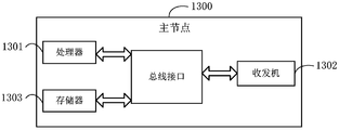
图13表示本公开实施例提供的主节点的再一结构示意图。
下面将参照附图更详细地描述本公开的示例性实施例。虽然附图中显示了本公开的示例性实施例,然而应当理解,可以以各种形式实现本公开而不应被这里阐述的实施例所限制。相反,提供这些实施例是为了能够更透彻地理解本公开,并且能够将本公开的范围完整的传达给本领域的技术人员。
本申请的说明书和权利要求书中的术语“第一”、“第二”等是用于区别类似的对象,而不必用于描述特定的顺序或先后次序。应该理解这样使用的数据在适当情况下可以互换,以便这里描述的本申请的实施例例如能够以除了在这里图示或描述的那些以外的顺序实施。此外,术语“包括”和“具有”以及他们的任何变形,意图在于覆盖不排他的包含,例如,包含了一系列步骤或单元的过程、方法、系统、产品或设备不必限于清楚地列出的那些步骤或单元,而是可包括没有清楚地列出的或对于这些过程、方法、产品或设备固有的其它步骤或单元。说明书以及权利要求中“和/或”表示所连接对象的至少其中之一。
本文所描述的技术不限于长期演进型(Long Time Evolution,LTE)/LTE的演进(LTE-Advanced,LTE-A)系统,并且也可用于各种无线通信系统,诸如码分多址(Code Division Multiple Access,CDMA)、时分多址(Time Division Multiple Access,TDMA)、频分多址(Frequency Division Multiple Access,FDMA)、正交频分多址(Orthogonal Frequency Division Multiple Access,OFDMA)、单载波频分多址(Single-carrier Frequency-Division Multiple Access,SC-FDMA)和其他系统。术语“系统”和“网络”常被可互换地使用。CDMA系统可实现诸如CDMA2000、通用地面无线电接入(Universal Terrestrial Radio Access,UTRA)等无线电技术。UTRA包括宽带CDMA(Wideband Code Division Multiple Access,WCDMA)和其他CDMA变体。TDMA系统可实现诸如全球移动通信系统(Global System for Mobile Communication,GSM)之类的无线电技术。OFDMA系统可实现诸如超移动宽带(Ultra-Mobile Broadband,UMB)、演进型UTRA(Evolution-UTRA,E-UTRA)、IEEE 802.11(Wi-Fi)、IEEE 802.16(WiMAX)、IEEE 802.20、Flash-OFDM等无线电技术。UTRA和E-UTRA是通用移动电信系统(Universal Mobile Telecommunications System,UMTS)的部分。LTE和更高级的LTE(如LTE-A)是使用E-UTRA的新UMTS版本。UTRA、E-UTRA、UMTS、LTE、LTE-A以及GSM在来自名为“第三代伙伴项目”(3rd Generation Partnership Project,3GPP)的组织的文献中描述。CDMA2000和UMB在来自名为“第三代伙伴项目2”(3GPP2)的组织的文献中描述。本文所描述的技术既可用于以上提及的系统和无线电技术,也可用于其他系统和无线电技术。然而,以下描述出于示例目的描述了LTE和NR系统,并且在以下大部分描述中使用LTE和NR术语,尽管这些技术也可应用于LTE和NR系统应用以外的应用。
以下描述提供示例而并非限定权利要求中阐述的范围、适用性或者配置。可以对所讨论的要素的功能和布置作出改变而不会脱离本公开的精神和范围。各种示例可适当地省略、替代、或添加各种规程或组件。例如,可以按不同于所描述的次序来执行所描述的方法,并且可以添加、省去、或组合各种步骤。另外,参照某些示例所描述的特征可在其他示例中被组合。
在NE-DC场景下,主节点为5G系统的无线接入网RAN节点gNB,辅 节点为E-UTRAN节点eNB。辅节点可以配置终端在自身制式下进行异频测量,即在LTE频点范围内进行异频测量,主节点可以配置终端进行NR频点(包括FR1和/或FR2)的异频测量,还可以配置终端对LTE频点进行异频测量。
在NE-DC场景下,由于MN变成了gNB,而gNB的异频测量频点可能包括LTE频点、NR系统的FR1频点或FR2频点,而LTE的异频测量频点只可能是LTE频点,因此一种可能的Measurement gap配置方案是由MN(gNB)来配置所有的Measurement gap方案,包括per UE和per FR的Measurement gap。
表1给出了目前NR系统支持的24种Measurement gap pattern的适用场景,其中,无论是per UE还是per FR的GAP配置,在双连接场景中,只要测量目标(Measurement Purpose)中出现了LTE(E-UTRA),Measurement gap pattern就只能配置ID为0~3的pattern。基于上述分析可以看出,对于SN来说,具体需要测量的频点信息可以不通知MN,但需要通过相关指示信息,如1bit的指示信息,告知MN在SN侧(即LTE eNB)也需要做异频测量。这样,MN才能给终端配置合理的Measurement GAP pattern。
表1


参见图5,本公开实施例提供了一种配置测量间隔的方法,应用于NE-DC场景下的辅节点,如图5所示,该方法包括:
步骤51,辅节点向主节点发送第一指示信息,所述第一指示信息用于表示辅节点需要配置所述终端进行E-UTRAN的异频测量或者用于请求主节点配置测量间隔。
这里,辅节点在需要配置所述终端进行E-UTRAN的异频测量、进而需要给终端测量间隔时,向主节点发送所述第一指示信息。为节约节点间的信令开销,所述第一指示信息可以采用预先约定的1比特位进行指示,例如,在所述1比特位取值为0时,表示辅节点需要配置所述终端进行E-UTRAN的异频测量,或者,所述1比特位取值为1时,表示辅节点需要配置所述终端进行E-UTRAN的异频测量。
请求主节点配置测量间隔可以是因为辅节点需要配置所述终端进行E-UTRAN的异频测量。在此条件下,辅节点向主节点发送第一指示信息,以请求主节点配置测量间隔。
具体地,辅节点可以通过节点间接口Xn,向主节点发送所述第一指示信息。所述第一指示信息,可以承载在SCG配置消息(SCG-Config)或CG配置消息(CG-Config)或其他自定义消息中进行传输。
通过以上步骤,本公开实施例可以在辅节点需要配置终端进行LTE系统下的异频测量、进而需要给终端测量间隔时向主节点进行指示,这样主节点在配置终端的测量间隔时,根据辅节点的指示,配置合适的测量间隔模式(Measurement gap pattern),例如,配置Measurement gap pattern ID为0~3中的一种测量间隔模式。
可选地,在辅节点不需要为终端配置演进的通用移动通信系统陆地无线 接入网络E-UTRAN的异频测量的情况下,本公开实施例的上述方法中,所述辅节点还可以向主节点发送第二指示信息,所述第二指示信息用于表示辅节点不需要配置所述终端进行E-UTRAN的异频测量或用于不请求主节点配置测量间隔。这里,所述第二指示信息,也可以通过所述第一指示信息的1比特位进行指示,其中,在所述1比特位取值为1时,表示辅节点不需要配置所述终端进行E-UTRAN的异频测量;或者,在所述1比特位取值为0时,表示辅节点不需要配置所述终端进行E-UTRAN的异频测量。
不请求主节点配置测量间隔可以是因为辅节点不需要配置所述终端进行E-UTRAN的异频测量。在此条件下,辅节点向主节点发送第二指示信息,用于不请求主节点配置测量间隔。
当然,本公开实施例在,辅节点在不需要为终端配置E-UTRAN的异频测量的情况下,还可以放弃向所述主节点发送所述第二指示信息,即不发送有关辅节点是否需要配置E-UTRAN的异频测量的指示信息,在这种情况下,主节点可以自行决定如何配置终端的测量间隔模式。通过上述处理,可以节约节点间信令开销。
以上从辅节点处介绍了本公开实施例的配置测量间隔的方法,接下来将结合图6进一步从主节点侧进行描述。
请参照图6,本公开实施例提供的配置测量间隔的方法,应用于NE-DC场景中的主节点,具体包括:
步骤61,主节点接收辅节点发送的第一指示信息,所述第一指示信息用于表示辅节点需要配置终端进行E-UTRAN的异频测量,或者,用于请求主节点配置测量间隔。
这里,所述第一指示信息通过预先约定的1比特位进行指示,其中,在所述1比特位取值为0时,表示辅节点需要配置所述终端进行E-UTRAN的异频测量,或者,所述1比特位取值为1时,表示辅节点需要配置所述终端进行E-UTRAN的异频测量。
请求主节点配置测量间隔可以是因为辅节点需要配置所述终端进行E-UTRAN的异频测量。在此条件下,辅节点向主节点发送第一指示信息,以请求主节点配置测量间隔。
通过以上步骤,主节点可以获得辅节点的异频测量配置的指示信息,从而据此为终端配置合理的测量间隔模式(Measurement gap pattern),例如,配置Measurement gap pattern ID为0~3中的一种测量间隔模式。
可选地,在上述步骤61之后,上述方法还可以包括:主节点根据所述第一指示信息,配置所述终端的Measurement gap pattern为测量间隔模式标识0~3中的一种。
请参照图7,本公开实施例提供的配置测量间隔的另一种方法,应用于NE-DC场景中的主节点,具体包括:
步骤71,主节点接收辅节点发送的第二指示信息,所述第二指示信息用于表示辅节点不需要配置终端进行E-UTRAN的异频测量,或者,用于不请求主节点配置测量间隔。
这里,所述第二指示信息,通过所述1比特位进行指示,其中,在所述1比特位取值为1时,表示辅节点不需要配置所述终端进行E-UTRAN的异频测量;或者,在所述1比特位取值为1时,表示辅节点不需要配置所述终端进行E-UTRAN的异频测量。
不请求主节点配置测量间隔可以是因为辅节点不需要配置所述终端进行E-UTRAN的异频测量。在此条件下,辅节点向主节点发送第二指示信息,用于不请求主节点配置测量间隔。
通过以上步骤,主节点可以获得辅节点的异频测量配置的指示信息,从而据此为终端配置合理的测量间隔模式(Measurement gap pattern),例如,配置Measurement gap pattern ID为0~23中的一种测量间隔模式。
可选地,在上述步骤71之后,上述方法还可以包括:主节点根据自身是否需要配置所述终端进行E-UTRAN的异频测量,配置所述终端的测量间隔模式Measurement gap pattern,其中,在主节点需要配置所述终端进行E-UTRAN的异频测量、进而需要给终端测量间隔时,配置所述终端的测量间隔模式Measurement gap pattern为测量间隔模式标识0~3中的一种。
以上分别从辅节点和主节点侧介绍了本公开实施例的配置测量间隔的方法。下面将进一步提供实施上述方法的辅节点和主节点。
参见图8,本公开的实施例还提供了一种NE-DC场景中的辅节点80,该 辅节点可以是eNB,包括处理器81和收发机82;
所述处理器81,用于确定需要为终端配置演进的通用移动通信系统陆地无线接入网络E-UTRAN的异频测量,从而需要配置测量间隔;
所述收发机82,用于在需要为终端配置演进的通用移动通信系统陆地无线接入网络E-UTRAN的异频测量的情况下,向主节点发送第一指示信息,所述第一指示信息用于表示辅节点需要配置所述终端进行E-UTRAN的异频测量,或者,用于请求主节点配置测量间隔。
请求主节点配置测量间隔可以是因为辅节点需要配置所述终端进行E-UTRAN的异频测量。在此条件下,辅节点向主节点发送第一指示信息,以请求主节点配置测量间隔。
本公开实施例的辅节点能够实现上述对应的应用于辅节点的方法实施例中的各个过程,并具有相应的有益效果,为避免重复,这里不再赘述。
这里,所述第一指示信息通过预先约定的1比特位进行指示,其中,在所述1比特位取值为0时,表示辅节点需要配置所述终端进行E-UTRAN的异频测量,或者,所述1比特位取值为1时,表示辅节点需要配置所述终端进行E-UTRAN的异频测量。
可选地,所述收发机82,还用于在不需要为终端配置E-UTRAN的异频测量的情况下,向主节点发送第二指示信息,或者,放弃向所述主节点发送所述第二指示信息,其中,所述第二指示信息用于表示辅节点不需要配置所述终端进行E-UTRAN的异频测量,或者,用于不请求主节点配置测量间隔。
这里,所述第二指示信息,通过所述1比特位进行指示,其中,在所述1比特位取值为1时,表示辅节点不需要配置所述终端进行E-UTRAN的异频测量;或者,在所述1比特位取值为0时,表示辅节点不需要配置所述终端进行E-UTRAN的异频测量。
不请求主节点配置测量间隔可以是因为辅节点不需要配置所述终端进行E-UTRAN的异频测量。在此条件下,辅节点向主节点发送第二指示信息,用于不请求主节点配置测量间隔。
这里,所述辅节点为5G系统的RAN节点gNB,所述主节点为E-UTRAN节点eNB。
请参照图9,本公开实施例还提供了另一种辅节点,该辅节点可以是eNB,如图9所示,该辅节点包括:处理器901、收发机902、存储器903和总线接口,其中:
在本公开实施例中,辅节点900还包括:存储在存储器上903并可在处理器901上运行的计算机程序,计算机程序被处理器901执行时实现如下步骤:在需要为终端配置演进的通用移动通信系统陆地无线接入网络E-UTRAN的异频测量的情况下,向主节点发送第一指示信息,所述第一指示信息用于表示辅节点需要配置所述终端进行E-UTRAN的异频测量,或者,用于请求主节点配置测量间隔。
请求主节点配置测量间隔可以是因为辅节点需要配置所述终端进行E-UTRAN的异频测量。在此条件下,辅节点向主节点发送第一指示信息,以请求主节点配置测量间隔。
在图9中,总线架构可以包括任意数量的互联的总线和桥,具体由处理器901代表的一个或多个处理器和存储器903代表的存储器的各种电路链接在一起。总线架构还可以将诸如外围设备、稳压器和功率管理电路等之类的各种其他电路链接在一起,这些都是本领域所公知的,因此,本文不再对其进行进一步描述。总线接口提供接口。收发机902可以是多个元件,即包括发送机和接收机,提供用于在传输介质上与各种其他装置通信的单元。
处理器901负责管理总线架构和通常的处理,存储器903可以存储处理器901在执行操作时所使用的数据。
这里,所述第一指示信息通过预先约定的1比特位进行指示,其中,在所述1比特位取值为0时,表示辅节点需要配置所述终端进行E-UTRAN的异频测量,或者,所述1比特位取值为1时,表示辅节点需要配置所述终端进行E-UTRAN的异频测量。
可选地,计算机程序被处理器903执行时还可实现如下步骤:在不需要为终端配置E-UTRAN的异频测量的情况下,向主节点发送第二指示信息,所述第二指示信息用于表示辅节点不需要配置所述终端进行E-UTRAN的异频测量,或者,用于不请求主节点配置测量间隔。
这里,所述第二指示信息,通过所述1比特位进行指示,其中,在所述 1比特位取值为1时,表示辅节点不需要配置所述终端进行E-UTRAN的异频测量;或者,在所述1比特位取值为0时,表示辅节点不需要配置所述终端进行E-UTRAN的异频测量。
这里,所述辅节点为E-UTRAN节点eNB,所述主节点为5G系统的无线接入网RAN节点gNB。
不请求主节点配置测量间隔可以是因为辅节点不需要配置所述终端进行E-UTRAN的异频测量。在此条件下,辅节点向主节点发送第二指示信息,用于不请求主节点配置测量间隔。
参见图10,本公开的实施例还提供了一种NE-DC场景中的主节点100,该主节点可以是gNB,包括处理器101和收发机102;
所述收发机,用于接收辅节点发送的第一指示信息,所述第一指示信息用于表示辅节点需要配置终端进行演进的通用移动通信系统陆地无线接入网络E-UTRAN的异频测量,或者,用于请求主节点配置测量间隔。
请求主节点配置测量间隔可以是因为辅节点需要配置所述终端进行E-UTRAN的异频测量。在此条件下,辅节点向主节点发送第一指示信息,以请求主节点配置测量间隔。
本公开实施例的主节点能够实现上述对应的应用于主节点的方法实施例中的各个过程,并具有相应的有益效果,为避免重复,这里不再赘述。
这里,所述第一指示信息通过预先约定的1比特位进行指示,其中,在所述1比特位取值为0时,表示辅节点需要配置所述终端进行E-UTRAN的异频测量,或者,所述1比特位取值为1时,表示辅节点需要配置所述终端进行E-UTRAN的异频测量。
这里,所述处理器101,可以用于主节点根据所述第一指示信息,配置所述终端的测量间隔模式Measurement gap pattern为测量间隔模式标识0~3中的一种。
请参照图11,本公开实施例还提供了另一种主节点,该主节点可以是gNB,如图11所示,该主节点包括:处理器1101、收发机1102、存储器1103和总线接口,其中:
在本公开实施例中,主节点1100还包括:存储在存储器上1103并可在 处理器1101上运行的计算机程序,计算机程序被处理器1101执行时实现如下步骤:接收辅节点发送的第一指示信息,所述第一指示信息用于表示辅节点需要配置终端进行演进的通用移动通信系统陆地无线接入网络E-UTRAN的异频测量,或者,用于请求主节点配置测量间隔。
请求主节点配置测量间隔可以是因为辅节点需要配置所述终端进行E-UTRAN的异频测量。在此条件下,辅节点向主节点发送第一指示信息,以请求主节点配置测量间隔。
在图11中,总线架构可以包括任意数量的互联的总线和桥,具体由处理器1101代表的一个或多个处理器和存储器1103代表的存储器的各种电路链接在一起。总线架构还可以将诸如外围设备、稳压器和功率管理电路等之类的各种其他电路链接在一起,这些都是本领域所公知的,因此,本文不再对其进行进一步描述。总线接口提供接口。收发机1102可以是多个元件,即包括发送机和接收机,提供用于在传输介质上与各种其他装置通信的单元。
处理器1101负责管理总线架构和通常的处理,存储器1103可以存储处理器1101在执行操作时所使用的数据。
这里,所述第一指示信息通过预先约定的1比特位进行指示,其中,在所述1比特位取值为0时,表示辅节点需要配置所述终端进行E-UTRAN的异频测量,或者,所述1比特位取值为1时,表示辅节点需要配置所述终端进行E-UTRAN的异频测量。
可选地,计算机程序被处理器1103执行时还可实现如下步骤:根据所述第一指示信息,配置所述终端的测量间隔模式Measurement gap pattern为测量间隔模式标识0~3中的一种。
参见图12,本公开一实施例还提供了一种NE-DC场景中的主节点120,该主节点具体可以是gNB,包括处理器121和收发机122;
所述收发机122,用于接收辅节点发送的第二指示信息,所述第二指示信息表示用于辅节点不需要配置终端进行演进的通用移动通信系统陆地无线接入网络E-UTRAN的异频测量,或者,用于不请求主节点配置测量间隔。
不请求主节点配置测量间隔可以是因为辅节点不需要配置所述终端进行E-UTRAN的异频测量。在此条件下,辅节点向主节点发送第二指示信息, 用于不请求主节点配置测量间隔。
本公开实施例的辅节点能够实现上述对应的应用于主节点的方法实施例中的各个过程,并具有相应的有益效果,为避免重复,这里不再赘述。
这里,所述第二指示信息,通过所述1比特位进行指示,其中,在所述1比特位取值为1时,表示辅节点不需要配置所述终端进行E-UTRAN的异频测量;或者,在所述1比特位取值为0时,表示辅节点不需要配置所述终端进行E-UTRAN的异频测量。
可选地,所述处理器121,可以用于根据自身是否需要配置所述终端进行演进的通用移动通信系统陆地无线接入网络E-UTRAN的异频测量,配置所述终端的测量间隔模式Measurement gap pattern,其中,在主节点需要配置所述终端进行E-UTRAN的异频测量、进而需要给终端测量间隔时,配置所述终端的测量间隔模式Measurement gap pattern为测量间隔模式标识0~3中的一种。
这里,所述主节点为5G系统的RAN节点gNB,所述辅节点为E-UTRAN节点eNB。
请参照图13,本公开实施例还提供了另一种主节点,该主节点可以是gNB,如图13所示,该主节点包括:处理器1301、收发机1302、存储器1303和总线接口,其中:
在本公开实施例中,主节点1300还包括:存储在存储器上1303并可在处理器1301上运行的计算机程序,计算机程序被处理器1301执行时实现如下步骤:接收辅节点发送的第二指示信息,所述第二指示信息用于表示辅节点不需要配置终端进行演进的通用移动通信系统陆地无线接入网络E-UTRAN的异频测量,或者,用于不请求主节点配置测量间隔。
不请求主节点配置测量间隔可以是因为辅节点不需要配置所述终端进行E-UTRAN的异频测量。在此条件下,辅节点向主节点发送第二指示信息,用于不请求主节点配置测量间隔。
在图13中,总线架构可以包括任意数量的互联的总线和桥,具体由处理器1301代表的一个或多个处理器和存储器1303代表的存储器的各种电路链接在一起。总线架构还可以将诸如外围设备、稳压器和功率管理电路等之类 的各种其他电路链接在一起,这些都是本领域所公知的,因此,本文不再对其进行进一步描述。总线接口提供接口。收发机1302可以是多个元件,即包括发送机和接收机,提供用于在传输介质上与各种其他装置通信的单元。
处理器1301负责管理总线架构和通常的处理,存储器1303可以存储处理器1301在执行操作时所使用的数据。
这里,所述第二指示信息,通过所述1比特位进行指示,其中,在所述1比特位取值为1时,表示辅节点不需要配置所述终端进行E-UTRAN的异频测量;或者,在所述1比特位取值为0时,表示辅节点不需要配置所述终端进行E-UTRAN的异频测量。
可选地,计算机程序被处理器1303执行时还可实现如下步骤:根据自身是否需要配置所述终端进行演进的通用移动通信系统陆地无线接入网络E-UTRAN的异频测量,配置所述终端的测量间隔模式Measurement gap pattern,其中,在主节点需要配置所述终端进行E-UTRAN的异频测量、进而需要给终端测量间隔时,配置所述终端的测量间隔模式Measurement gap pattern为测量间隔模式标识0~3中的一种。
这里,所述辅节点为E-UTRAN节点eNB,所述主节点为5G系统的无线接入网RAN节点gNB。
本领域普通技术人员可以意识到,结合本文中所公开的实施例描述的各示例的单元及算法步骤,能够以电子硬件、或者计算机软件和电子硬件的结合来实现。这些功能究竟以硬件还是软件方式来执行,取决于技术方案的特定应用和设计约束条件。专业技术人员可以对每个特定的应用来使用不同方法来实现所描述的功能,但是这种实现不应认为超出本公开的范围。
所属领域的技术人员可以清楚地了解到,为描述的方便和简洁,上述描述的系统、装置和单元的具体工作过程,可以参考前述方法实施例中的对应过程,在此不再赘述。
在本申请所提供的实施例中,应该理解到,所揭露的装置和方法,可以通过其它的方式实现。例如,以上所描述的装置实施例仅仅是示意性的,例如,所述单元的划分,仅仅为一种逻辑功能划分,实际实现时可以有另外的划分方式,例如多个单元或组件可以结合或者可以集成到另一个系统,或一 些特征可以忽略,或不执行。另一点,所显示或讨论的相互之间的耦合或直接耦合或通信连接可以是通过一些接口,装置或单元的间接耦合或通信连接,可以是电性,机械或其它的形式。
所述作为分离部件说明的单元可以是或者也可以不是物理上分开的,作为单元显示的部件可以是或者也可以不是物理单元,即可以位于一个地方,或者也可以分布到多个网络单元上。可以根据实际的需要选择其中的部分或者全部单元来实现本公开实施例方案的目的。
另外,在本公开各个实施例中的各功能单元可以集成在一个处理单元中,也可以是各个单元单独物理存在,也可以两个或两个以上单元集成在一个单元中。
所述功能如果以软件功能单元的形式实现并作为独立的产品销售或使用时,可以存储在一个计算机可读取存储介质中。基于这样的理解,本公开的技术方案本质上或者说对相关技术做出贡献的部分或者该技术方案的部分可以以软件产品的形式体现出来,该计算机软件产品存储在一个存储介质中,包括若干指令用以使得一台计算机设备(可以是个人计算机,服务器,或者网络设备等)执行本公开各个实施例所述配置测量间隔的方法的全部或部分步骤。而前述的存储介质包括:U盘、移动硬盘、ROM、RAM、磁碟或者光盘等各种可以存储程序代码的介质。
以上所述,仅为本公开的具体实施方式,但本公开的保护范围并不局限于此,任何熟悉本技术领域的技术人员在本公开揭露的技术范围内,可轻易想到变化或替换,都应涵盖在本公开的保护范围之内。因此,本公开的保护范围应以权利要求的保护范围为准。
Claims (28)
- 一种配置测量间隔的方法,应用于新空口-演进的通用移动通信系统陆地无线接入-双连接NE-DC场景,其中,所述方法包括:辅节点向主节点发送第一指示信息,所述第一指示信息用于表示辅节点需要配置所述终端进行E-UTRAN的异频测量,或者,用于请求主节点配置测量间隔。
- 根据权利要求1所述的方法,其中,所述第一指示信息通过预先约定的1比特位进行指示,其中,在所述1比特位取值为0时,表示辅节点需要配置所述终端进行E-UTRAN的异频测量,或者,在所述1比特位取值为1时,表示辅节点需要配置所述终端进行E-UTRAN的异频测量。
- 根据权利要求2所述的方法,其中,所述方法还包括:所述辅节点在不需要为终端配置E-UTRAN的异频测量的情况下,向主节点发送第二指示信息,或者,放弃向所述主节点发送所述第二指示信息,其中,所述第二指示信息用于表示辅节点不需要配置所述终端进行E-UTRAN的异频测量,或者,用于不请求主节点配置测量间隔。
- 根据权利要求3所述的方法,其中,所述第二指示信息,通过所述1比特位进行指示,其中,在所述1比特位取值为1时,表示辅节点不需要配置所述终端进行E-UTRAN的异频测量;或者,在所述1比特位取值为0时,表示辅节点不需要配置所述终端进行E-UTRAN的异频测量。
- 根据权利要求1所述的方法,其中,所述辅节点为E-UTRAN节点eNB,所述主节点为5G系统的无线接入网RAN节点gNB。
- 一种配置测量间隔的方法,应用于新空口-演进的通用移动通信系统陆地无线接入-双连接NE-DC场景,其中,所述方法包括:主节点接收辅节点发送的第一指示信息,所述第一指示信息用于表示辅节点需要配置终端进行演进的通用移动通信系统陆地无线接入网络E-UTRAN的异频测量,或者,用于请求主节点配置测量间隔。
- 根据权利要求6所述的方法,其中,在接收所述第一指示信息之后,所述方法还包括:主节点根据所述第一指示信息,配置所述终端的测量间隔模式Measurement gap pattern为测量间隔模式标识0~3中的一种。
- 根据权利要求6所述的方法,其中,所述第一指示信息通过预先约定的1比特位进行指示,其中,在所述1比特位取值为0时,表示辅节点需要配置所述终端进行E-UTRAN的异频测量,或者,所述1比特位取值为1时,表示辅节点需要配置所述终端进行E-UTRAN的异频测量。
- 根据权利要求6至8任一项所述的方法,其中,所述主节点为5G系统的无线接入网RAN节点gNB,所述辅节点为演进的通用移动通信系统陆地无线接入网络E-UTRAN节点eNB。
- 一种配置测量间隔的方法,应用于新空口-演进的通用移动通信系统陆地无线接入-双连接NE-DC场景,其中,所述方法包括:主节点接收辅节点发送的第二指示信息,所述第二指示信息用于表示辅节点不需要配置终端进行演进的通用移动通信系统陆地无线接入网络E-UTRAN的异频测量,或者,用于不请求主节点配置测量间隔。
- 根据权利要求10所述的方法,其中,在接收所述第二指示信息之后,所述方法还包括:主节点根据自身是否需要配置所述终端进行E-UTRAN的异频测量,配置所述终端的测量间隔模式Measurement gap pattern,其中,在主节点需要配置所述终端进行E-UTRAN的异频测量、进而需要给终端测量间隔时,配置所述终端的测量间隔模式Measurement gap pattern为测量间隔模式标识0~3中的一种。
- 根据权利要求10所述的方法,其中,所述第二指示信息,通过1比特位进行指示,其中,在所述1比特位取值为1时,表示辅节点不需要配置所述终端进行E-UTRAN的异频测量;或者,在所述1比特位取值为0时,表示辅节点不需要配置所述终端进行E-UTRAN的异频测量。
- 根据权利要求10至12任一项所述的方法,其中,所述主节点为5G系统的无线接入网RAN节点gNB,所述辅节点为演进的通用移动通信系统陆地无线接入网络E-UTRAN节点eNB。
- 一种新空口-演进的通用移动通信系统陆地无线接入-双连接NE-DC场景中的辅节点,其中,包括处理器和收发机;所述处理器,用于确定需要为终端配置演进的通用移动通信系统陆地无线接入网络E-UTRAN的异频测量,从而需要配置测量间隔;所述收发机,用于在需要为终端配置演进的通用移动通信系统陆地无线接入网络E-UTRAN的异频测量的情况下,向主节点发送第一指示信息,所述第一指示信息用于表示辅节点需要配置所述终端进行E-UTRAN的异频测量,或者,用于请求主节点配置测量间隔。
- 根据权利要求14所述的辅节点,其中,所述第一指示信息通过预先约定的1比特位进行指示,其中,在所述1比特位取值为0时,表示辅节点需要配置所述终端进行E-UTRAN的异频测量,或者,所述1比特位取值为1时,表示辅节点需要配置所述终端进行E-UTRAN的异频测量。
- 根据权利要求15所述的辅节点,其中,所述收发机,还用于在不需要为终端配置E-UTRAN的异频测量的情况下,向主节点发送第二指示信息,或者,放弃向所述主节点发送所述第二指示信息,其中,所述第二指示信息用于表示辅节点不需要配置所述终端进行E-UTRAN的异频测量,或者,用于不请求主节点配置测量间隔。
- 根据权利要求16所述的辅节点,其中,所述第二指示信息,通过1比特位进行指示,其中,在所述1比特位取值为1时,表示辅节点不需要配置所述终端进行E-UTRAN的异频测量;或者,在所述1比特位取值为0时,表示辅节点不需要配置所述终端进行E-UTRAN的异频测量。
- 根据权利要求14所述的辅节点,其中,所述辅节点为5G系统的无线接入网RAN节点gNB,所述主节点为演进的通用移动通信系统陆地无线接入网络E-UTRAN节点eNB。
- 一种新空口-演进的通用移动通信系统陆地无线接入-双连接NE-DC场景中的主节点,其中,包括处理器和收发机;所述收发机,用于接收辅节点发送的第一指示信息,所述第一指示信息用于表示辅节点需要配置终端进行演进的通用移动通信系统陆地无线接入网络E-UTRAN的异频测量,或者,用于请求主节点配置测量间隔。
- 根据权利要求19所述的主节点,其中,所述处理器,用于根据所述第一指示信息,配置所述终端的测量间隔模式Measurement gap pattern为测量间隔模式标识0~3中的一种。
- 根据权利要求19所述的主节点,其中,所述第一指示信息通过预先约定的1比特位进行指示,其中,在所述1比特位取值为0时,表示辅节点需要配置所述终端进行E-UTRAN的异频测量,或者,所述1比特位取值为1时,表示辅节点需要配置所述终端进行E-UTRAN的异频测量。
- 根据权利要求19至21任一项所述的主节点,其中,所述主节点为5G系统的无线接入网RAN节点gNB,所述辅节点为演进的通用移动通信系统陆地无线接入网络E-UTRAN节点eNB。
- 一种新空口-演进的通用移动通信系统陆地无线接入-双连接NE-DC场景中的主节点,其中,包括处理器和收发机;所述收发机,用于接收辅节点发送的第二指示信息,所述第二指示信息用于表示辅节点不需要配置终端进行演进的通用移动通信系统陆地无线接入网络E-UTRAN的异频测量,或者,用于不请求主节点配置测量间隔。
- 根据权利要求23所述的主节点,其中,所述处理器,用于根据自身是否需要配置所述终端进行演进的通用移动通信系统陆地无线接入网络E-UTRAN的异频测量,配置所述终端的测量间隔模式Measurement gap pattern,其中,在主节点需要配置所述终端进行E-UTRAN的异频测量、进而需要给终端测量间隔时,配置所述终端的测量间隔模式Measurement gap pattern为测量间隔模式标识0~3中的一种。
- 根据权利要求23所述的主节点,其中,所述第二指示信息,通过1比特位进行指示,其中,在所述1比特位取 值为1时,表示辅节点不需要配置所述终端进行E-UTRAN的异频测量;或者,在所述1比特位取值为0时,表示辅节点不需要配置所述终端进行E-UTRAN的异频测量。
- 根据权利要求23至25任一项所述的主节点,其中,所述主节点为5G系统的无线接入网RAN节点gNB,所述辅节点为演进的通用移动通信系统陆地无线接入网络E-UTRAN节点eNB。
- 一种通信设备,包括:处理器、存储有计算机程序的存储器,所述计算机程序被处理器运行时,执行如权利要求1至13任一项所述的方法。
- 一种计算机可读存储介质,包括指令,当所述指令在计算机运行时,使得计算机执行如权利要求1至13任一项所述的方法。
Priority Applications (2)
| Application Number | Priority Date | Filing Date | Title |
|---|---|---|---|
| US17/254,504 US11617098B2 (en) | 2018-06-21 | 2019-06-21 | Measurement gap configuration method and device |
| EP19822574.0A EP3813409A4 (en) | 2018-06-21 | 2019-06-21 | METHOD AND DEVICE FOR CONFIGURING A MEASUREMENT GAP |
Applications Claiming Priority (2)
| Application Number | Priority Date | Filing Date | Title |
|---|---|---|---|
| CN201810644192.8A CN110636519B (zh) | 2018-06-21 | 2018-06-21 | 一种配置测量间隔的方法及设备 |
| CN201810644192.8 | 2018-06-21 |
Publications (1)
| Publication Number | Publication Date |
|---|---|
| WO2019242732A1 true WO2019242732A1 (zh) | 2019-12-26 |
Family
ID=68966477
Family Applications (1)
| Application Number | Title | Priority Date | Filing Date |
|---|---|---|---|
| PCT/CN2019/092281 Ceased WO2019242732A1 (zh) | 2018-06-21 | 2019-06-21 | 配置测量间隔的方法及设备 |
Country Status (4)
| Country | Link |
|---|---|
| US (1) | US11617098B2 (zh) |
| EP (1) | EP3813409A4 (zh) |
| CN (1) | CN110636519B (zh) |
| WO (1) | WO2019242732A1 (zh) |
Families Citing this family (9)
| Publication number | Priority date | Publication date | Assignee | Title |
|---|---|---|---|---|
| CN110831053B (zh) * | 2018-08-07 | 2021-06-25 | 维沃移动通信有限公司 | 测量间隔的配置方法及网络节点 |
| WO2020031122A1 (en) * | 2018-08-09 | 2020-02-13 | Telefonaktiebolaget Lm Ericsson (Publ) | Measurement gap configuration in ne-dc and nr-nr dc |
| WO2020061984A1 (en) * | 2018-09-28 | 2020-04-02 | Qualcomm Incorporated | Measurement gap configuration and coordination |
| US20220338286A1 (en) * | 2019-09-09 | 2022-10-20 | Telefonaktiebolaget Lm Ericsson (Publ) | Methods and devices in a dual connectivity network |
| EP4075872B1 (en) | 2020-01-02 | 2024-10-09 | Guangdong Oppo Mobile Telecommunications Corp., Ltd. | Cell reselection method and apparatus, terminal device, and network device |
| WO2021212258A1 (zh) * | 2020-04-20 | 2021-10-28 | Oppo广东移动通信有限公司 | 一种上报指示信息的方法及装置、终端设备、网络设备 |
| WO2022006909A1 (zh) * | 2020-07-10 | 2022-01-13 | Oppo广东移动通信有限公司 | 测量间隔的配置方法、网络设备及终端设备 |
| CN116530131B (zh) * | 2020-10-16 | 2025-06-06 | 华为技术有限公司 | 测量间隔的配置方法及装置 |
| CN115499918B (zh) * | 2021-06-17 | 2026-02-27 | 维沃移动通信有限公司 | Gap请求消息的发送/接收方法和设备 |
Citations (2)
| Publication number | Priority date | Publication date | Assignee | Title |
|---|---|---|---|---|
| CN106233765A (zh) * | 2014-04-30 | 2016-12-14 | Lg电子株式会社 | 在无线通信系统中配置测量间隙的方法和装置 |
| CN106416350A (zh) * | 2014-02-24 | 2017-02-15 | 英特尔Ip公司 | 测量间隙模式 |
Family Cites Families (3)
| Publication number | Priority date | Publication date | Assignee | Title |
|---|---|---|---|---|
| CN107040956B (zh) * | 2016-02-03 | 2021-07-30 | 中国移动通信集团公司 | 一种物联网中测量上报管理方法、终端及基站 |
| CN118201001A (zh) * | 2018-01-11 | 2024-06-14 | 瑞典爱立信有限公司 | 第一基站、第二基站、用户设备以及由它们执行的用于处理一个或多个测量的改变的方法 |
| US11729782B2 (en) * | 2018-06-11 | 2023-08-15 | Apple Inc. | Enhanced uplink beam management |
-
2018
- 2018-06-21 CN CN201810644192.8A patent/CN110636519B/zh active Active
-
2019
- 2019-06-21 WO PCT/CN2019/092281 patent/WO2019242732A1/zh not_active Ceased
- 2019-06-21 EP EP19822574.0A patent/EP3813409A4/en active Pending
- 2019-06-21 US US17/254,504 patent/US11617098B2/en active Active
Patent Citations (2)
| Publication number | Priority date | Publication date | Assignee | Title |
|---|---|---|---|---|
| CN106416350A (zh) * | 2014-02-24 | 2017-02-15 | 英特尔Ip公司 | 测量间隙模式 |
| CN106233765A (zh) * | 2014-04-30 | 2016-12-14 | Lg电子株式会社 | 在无线通信系统中配置测量间隙的方法和装置 |
Non-Patent Citations (2)
| Title |
|---|
| RAN2: "Presentation of Specification TS 37.340, Version 1.0.0", 3GPP TSG-RAN MEETING #77, RP-171872, 4 September 2017 (2017-09-04), XP051668717 * |
| See also references of EP3813409A4 * |
Also Published As
| Publication number | Publication date |
|---|---|
| CN110636519B (zh) | 2021-07-13 |
| US20210136616A1 (en) | 2021-05-06 |
| CN110636519A (zh) | 2019-12-31 |
| US11617098B2 (en) | 2023-03-28 |
| EP3813409A4 (en) | 2022-04-06 |
| EP3813409A1 (en) | 2021-04-28 |
Similar Documents
| Publication | Publication Date | Title |
|---|---|---|
| CN110636519B (zh) | 一种配置测量间隔的方法及设备 | |
| BR112019019865A2 (pt) | método de transmissão de informação e dispositivo de rede | |
| WO2021023062A1 (zh) | 测量的方法、测量指示的方法和设备 | |
| CN112654052B (zh) | 一种pci冲突的检测、调整方法以及设备 | |
| BR112019026416A2 (pt) | método para a configuração de anr e dispositivo terminal | |
| BR112015025368B1 (pt) | Métodos para adquirir uma capacidade de equipamento de usuário e estação base | |
| CN111247828A (zh) | 用于主节点和辅节点测量的单个测量间隙 | |
| CN109792599B (zh) | 会话管理方法及网元 | |
| BR112020012794A2 (pt) | método de localização em uma rede de conectividade múltipla, dispositivo terminal e entidade de função de gerenciamento de localização | |
| CN112106399A (zh) | 用于确定测量间隙的方法、设备和计算机可读介质 | |
| BR112019026433A2 (pt) | método de comunicação de rádio, dispositivo de terminal e dispositivo de rede | |
| CA3055098C (en) | Data transmission method and device | |
| WO2020042981A1 (zh) | 空间相关信息的指示方法和设备 | |
| KR20210010498A (ko) | Rrm 측정 구성을 결정하는 방법 및 장치 | |
| WO2016045129A1 (zh) | 双连接中服务小区的配置方法、用户设备和基站 | |
| BR112019013671B1 (pt) | Método de transmissão de informações, dispositivo de rede e dispositivo terminal | |
| CN111417131B (zh) | 一种测量配置的方法及设备 | |
| CN110999517A (zh) | 用于设备到设备(d2d)通信的方法和设备 | |
| JP2013051549A (ja) | 通信システム、通信方法、基地局、および、移動局 | |
| CN111132217A (zh) | 通信方法与装置 | |
| CN110856187B (zh) | 一种测量配置的方法及设备 | |
| EP3175598A1 (en) | Message-based path selection for transport protocols supporting multiple transport paths | |
| CN110662269B (zh) | 一种系统消息的发送方法、接收方法及设备 | |
| US20200028641A1 (en) | Signal transmission method and apparatus | |
| WO2021032187A1 (zh) | 链路失败处理的方法和通信设备 |
Legal Events
| Date | Code | Title | Description |
|---|---|---|---|
| 121 | Ep: the epo has been informed by wipo that ep was designated in this application |
Ref document number: 19822574 Country of ref document: EP Kind code of ref document: A1 |
|
| NENP | Non-entry into the national phase |
Ref country code: DE |
|
| WWE | Wipo information: entry into national phase |
Ref document number: 2019822574 Country of ref document: EP |
|
| ENP | Entry into the national phase |
Ref document number: 2019822574 Country of ref document: EP Effective date: 20210121 |