WO2019244344A1 - 回転翼及びこの回転翼を備える遠心圧縮機 - Google Patents
回転翼及びこの回転翼を備える遠心圧縮機 Download PDFInfo
- Publication number
- WO2019244344A1 WO2019244344A1 PCT/JP2018/023830 JP2018023830W WO2019244344A1 WO 2019244344 A1 WO2019244344 A1 WO 2019244344A1 JP 2018023830 W JP2018023830 W JP 2018023830W WO 2019244344 A1 WO2019244344 A1 WO 2019244344A1
- Authority
- WO
- WIPO (PCT)
- Prior art keywords
- edge
- blade
- surface portion
- curved surface
- side edge
- Prior art date
- Legal status (The legal status is an assumption and is not a legal conclusion. Google has not performed a legal analysis and makes no representation as to the accuracy of the status listed.)
- Ceased
Links
Images






Classifications
-
- F—MECHANICAL ENGINEERING; LIGHTING; HEATING; WEAPONS; BLASTING
- F04—POSITIVE - DISPLACEMENT MACHINES FOR LIQUIDS; PUMPS FOR LIQUIDS OR ELASTIC FLUIDS
- F04D—NON-POSITIVE-DISPLACEMENT PUMPS
- F04D29/00—Details, component parts, or accessories
- F04D29/26—Rotors specially for elastic fluids
- F04D29/28—Rotors specially for elastic fluids for centrifugal or helico-centrifugal pumps for radial-flow or helico-centrifugal pumps
- F04D29/284—Rotors specially for elastic fluids for centrifugal or helico-centrifugal pumps for radial-flow or helico-centrifugal pumps for compressors
-
- F—MECHANICAL ENGINEERING; LIGHTING; HEATING; WEAPONS; BLASTING
- F04—POSITIVE - DISPLACEMENT MACHINES FOR LIQUIDS; PUMPS FOR LIQUIDS OR ELASTIC FLUIDS
- F04D—NON-POSITIVE-DISPLACEMENT PUMPS
- F04D17/00—Radial-flow pumps, e.g. centrifugal pumps; Helico-centrifugal pumps
- F04D17/08—Centrifugal pumps
- F04D17/10—Centrifugal pumps for compressing or evacuating
-
- F—MECHANICAL ENGINEERING; LIGHTING; HEATING; WEAPONS; BLASTING
- F04—POSITIVE - DISPLACEMENT MACHINES FOR LIQUIDS; PUMPS FOR LIQUIDS OR ELASTIC FLUIDS
- F04D—NON-POSITIVE-DISPLACEMENT PUMPS
- F04D29/00—Details, component parts, or accessories
- F04D29/26—Rotors specially for elastic fluids
- F04D29/28—Rotors specially for elastic fluids for centrifugal or helico-centrifugal pumps for radial-flow or helico-centrifugal pumps
- F04D29/30—Vanes
-
- F—MECHANICAL ENGINEERING; LIGHTING; HEATING; WEAPONS; BLASTING
- F04—POSITIVE - DISPLACEMENT MACHINES FOR LIQUIDS; PUMPS FOR LIQUIDS OR ELASTIC FLUIDS
- F04D—NON-POSITIVE-DISPLACEMENT PUMPS
- F04D29/00—Details, component parts, or accessories
- F04D29/26—Rotors specially for elastic fluids
- F04D29/32—Rotors specially for elastic fluids for axial flow pumps
- F04D29/38—Blades
- F04D29/384—Blades characterised by form
-
- F—MECHANICAL ENGINEERING; LIGHTING; HEATING; WEAPONS; BLASTING
- F05—INDEXING SCHEMES RELATING TO ENGINES OR PUMPS IN VARIOUS SUBCLASSES OF CLASSES F01-F04
- F05D—INDEXING SCHEME FOR ASPECTS RELATING TO NON-POSITIVE-DISPLACEMENT MACHINES OR ENGINES, GAS-TURBINES OR JET-PROPULSION PLANTS
- F05D2240/00—Components
- F05D2240/20—Rotors
- F05D2240/30—Characteristics of rotor blades, i.e. of any element transforming dynamic fluid energy to or from rotational energy and being attached to a rotor
- F05D2240/304—Characteristics of rotor blades, i.e. of any element transforming dynamic fluid energy to or from rotational energy and being attached to a rotor related to the trailing edge of a rotor blade
-
- F—MECHANICAL ENGINEERING; LIGHTING; HEATING; WEAPONS; BLASTING
- F05—INDEXING SCHEMES RELATING TO ENGINES OR PUMPS IN VARIOUS SUBCLASSES OF CLASSES F01-F04
- F05D—INDEXING SCHEME FOR ASPECTS RELATING TO NON-POSITIVE-DISPLACEMENT MACHINES OR ENGINES, GAS-TURBINES OR JET-PROPULSION PLANTS
- F05D2240/00—Components
- F05D2240/20—Rotors
- F05D2240/30—Characteristics of rotor blades, i.e. of any element transforming dynamic fluid energy to or from rotational energy and being attached to a rotor
- F05D2240/306—Characteristics of rotor blades, i.e. of any element transforming dynamic fluid energy to or from rotational energy and being attached to a rotor related to the suction side of a rotor blade
Definitions
- the present disclosure relates to a rotor and a centrifugal compressor including the rotor.
- Patent Document 1 describes a centrifugal compressor in which the operating range is expanded to a low flow rate side while ensuring sufficient structural strength of the impeller.
- a curved surface is formed on the pressure surface of each blade provided on the impeller so that the center of the edge portion of the trailing edge is moved toward the negative pressure surface side.
- the formation of the curved surface portion disclosed in Patent Document 1 on the pressure surface side of the blade can expand the operation range to the low flow rate side while ensuring sufficient structural strength of the impeller. It has been found that the pressure ratio drops. On the other hand, it has been clarified that the pressure ratio can be improved by forming a curved surface portion on the negative pressure surface side of the blade.
- At least one embodiment of the present disclosure has an object to provide a rotor that can improve a pressure ratio and a centrifugal compressor including the rotor.
- the rotor includes: Hub and A rotor comprising a plurality of blades provided on the hub, Each of the plurality of blades includes a suction surface, a pressure surface, a leading edge, a trailing edge, a tip side edge, and a hub side edge, The negative pressure surface is directed to the rear edge so as to bring the rear edge closer to the pressure surface side in a first region that is a part of the region connected to the rear edge in the blade height direction of the blade. And a first curved surface portion that is convexly curved.
- the flow direction of the fluid flowing from the leading edge to the trailing edge along the negative pressure surface is largely bent by flowing along the first curved surface portion, and around the trailing edge. It comes to approximate the direction of rotation of the rotor.
- Such a change in the flow direction of the air increases the work of the fluid on the rotor, so that the pressure ratio due to the rotation of the rotor can be improved.
- the first curved surface portion is connected to the hub side edge.
- the first curved surface portion is formed in a region which is equal to or less than 80% of a blade height from the hub side edge in a direction from the hub side edge to the chip side edge.
- the effect of improving the pressure ratio by forming the first curved surface portion on the negative pressure surface becomes greater as the first curved surface portion is closer to the hub side edge. According to the configurations of (2) and (3), since the first curved surface portion is formed near the hub side edge, the effect of improving the pressure ratio can be further enhanced.
- any one of the above (1) to (3) In a cross section perpendicular to the meridional plane of the blade, an angle formed by a tangent of the first curved surface portion with respect to a code line which is a straight line connecting the leading edge and the trailing edge increases toward the trailing edge.
- the first curved surface portion is configured.
- the flow direction of the fluid flowing from the leading edge to the trailing edge along the negative pressure surface is further greatly bent by flowing along the first curved surface portion, and around the trailing edge. With this, it becomes more approximate to the rotation direction of the rotor.
- Such a change in the flow direction of air further increases the work of the fluid on the rotor, so that the pressure ratio due to the rotation of the rotor can be further improved.
- the pressure surface is directed toward the trailing edge so as to bring the trailing edge closer to the suction surface side in a second region that is a part of the region connected to the trailing edge in the blade height direction of the blade. And a second curved surface portion curved in a convex shape.
- the boundary layer generated when the fluid flows along the pressure surface is reduced at the second curved surface portion, and the flow of the fluid along the pressure surface is promoted.
- the compression efficiency by rotation can be improved.
- the second curved surface portion is connected to the side edge of the chip.
- the second curved surface portion is formed in a region of 70% or less of the blade height from the tip side edge in a direction from the tip side edge to the hub side edge.
- the effect of improving the compression efficiency by the rotation of the rotating blade by forming the second curved surface portion on the pressure surface becomes greater as the second curved surface portion is closer to the tip side edge.
- the effect of improving the compression efficiency by the rotation of the rotary blade can be further enhanced.
- any one of the above (5) to (7) In a cross section perpendicular to the meridian plane of the blade, an angle between a tangent at the rear edge of the second curved surface portion to a code line that is a straight line connecting the front edge and the rear edge is Therefore, the angle is smaller than the angle formed by the tangent at the trailing edge of the first curved surface portion.
- the first curved surface portion is more greatly curved than the second curved surface portion. For this reason, the boundary layer area formed near the trailing edge of the blade is reduced by the fluid flowing along the second curved surface portion, and the compression efficiency due to the rotation of the rotary blade is improved.
- the trailing edge is straight from the hub side edge toward the chip side edge. According to the configuration (9), the trailing edge is straight from the hub side edge toward the tip side edge, so that the workability of blade manufacturing can be improved.
- the centrifugal compressor according to at least one embodiment of the present invention includes: The rotary wing according to any one of the above (1) to (9) is provided. According to the above configuration (10), the pressure ratio of the centrifugal compressor can be improved.
- the flow direction of the fluid flowing from the leading edge to the trailing edge along the suction surface is largely bent by flowing along the first curved surface portion, and passes the trailing edge. In the vicinity, it comes to approximate the direction of rotation of the rotor.
- Such a change in the flow direction of the air increases the work of the fluid on the rotor, so that the pressure ratio due to the rotation of the rotor can be improved.
- FIG. 1 is a meridional view of a centrifugal compressor including a rotor according to Embodiment 1 of the present disclosure.
- FIG. 2 is a cross-sectional view of blades provided on the rotor according to Embodiment 1 of the present disclosure at equal span heights.
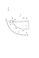
- FIG. 2 is a partial cross-sectional view perpendicular to the meridional plane near a trailing edge of a blade provided on the rotor according to the first embodiment of the present disclosure. It is a graph which shows the result obtained by CFD analysis about the relation between the volume flow rate of air, and a pressure ratio. 9 is a graph showing a result obtained by a CFD analysis on a change in a slip amount when a range of a first region is changed.
- FIG. 1 is a meridional view of a centrifugal compressor including a rotor according to Embodiment 1 of the present disclosure.
- FIG. 2 is a cross-sectional view of blades provided on the rotor according
- FIG. 11 is a meridional view on a pressure surface side near a trailing edge of a blade provided on a rotor according to a second embodiment of the present disclosure.
- FIG. 7 is a sectional view taken along the line VII-VII in FIG. 6. It is a perspective view near the trailing edge of the blade provided in the rotor according to Embodiment 2 of the present disclosure. It is a graph which shows the result obtained by CFD analysis about the relation between the volumetric flow rate of air and compression efficiency.
- FIG. 5 is a diagram showing a result obtained by CFD analysis on a flow velocity distribution in a boundary layer formed on a suction surface and a pressure surface of the blade (b) in FIG. 4.
- FIG. 5 is a diagram showing a result obtained by CFD analysis on a flow velocity distribution in a boundary layer formed on a suction surface and a pressure surface of the blade (b) in FIG. 4.
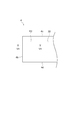
- FIG. 10 is a partial cross-sectional view illustrating a curved shape of each of a first curved surface portion and a second curved surface portion of a rotor according to a second embodiment of the present disclosure. It is a graph which shows the result obtained by CFD analysis about change of the flow velocity in a boundary layer when changing the range of the 2nd field. It is a front view near the trailing edge of the modification of the blade provided in the rotor according to Embodiment 2 of the present disclosure.
- the centrifugal compressor in the present disclosure is not limited to a turbocharger centrifugal compressor, and may be any centrifugal compressor that operates alone.
- the rotor of the present disclosure also includes a rotor used for a turbine or an axial flow pump.
- the fluid compressed by the centrifugal compressor is air, but can be replaced with any fluid.
- the centrifugal compressor 1 includes a housing 2 and an impeller 3 rotatably provided around a rotation axis L in the housing 2.
- the impeller 3 has a plurality of streamline-shaped blades 4 (only one blade 4 is illustrated in FIG. 1) provided on the hub 5 at predetermined intervals in the circumferential direction.
- Each blade 4 includes a leading edge 4a, a trailing edge 4b, a tip side edge 4c facing the housing 2, and a hub side edge 4d connecting to the hub 5.
- each blade 4 a part of the region connected to the trailing edge 4b in the blade height direction of the blade 4 is defined as a first region R1.
- the negative pressure surface 10 of each blade 4 has a first curved surface portion convexly curved toward the rear edge 4 b so as to move the rear edge 4 b toward the pressure surface 20 in the first region R ⁇ b> 1.
- 11 is included.
- a vertical line PL1 is drawn through the edge 11a on the front edge 4a side of the first curved surface portion 11 and perpendicular to the center line CL1 of the blade 4.
- a straight line obtained by extending the center line CL1 from the front edge 4a to the vertical line PL1 toward the rear edge 4b from the vertical line PL1 is an extension line EL1
- the rear edge 4b exerts a pressure on the extension line EL1. It is located on the surface 20 side.
- the convex curvature of the first curved surface portion 11 is different from that of the first curved surface portion 11 with respect to the code line CL2 which is a straight line connecting the front edge 4a (see FIG. 2) and the rear edge 4b.
- the shape is such that the angle between the tangents increases toward the trailing edge 4b. That is, when each of the tangent TL2 tangent TL1 and trailing edges 4b side from the tangential line TL1 of the first bending portion 11, respectively, and theta 1 and theta 2 the angle with respect to the code line CL2, a theta 1 ⁇ theta 2 Is preferred.
- the present inventors have confirmed the effect of the first curved surface portion 11 by CFD analysis.
- the result is shown in FIG.
- the pressure surface 20 shown in (b) is used in addition to the blade (shown in (a)) of Embodiment 1 having the first curved surface portion 11 on the suction surface 10.
- the volume flow rate of the air obtained by CFD analysis was obtained for a blade having a curved surface portion 9 and a blade having a substantially elliptical cross section near the trailing edge 4b as shown in FIG.
- the relationship with the pressure ratio is shown. From this relationship, it can be confirmed that the blade of the first embodiment having the first curved surface portion 11 on the negative pressure surface 10 has an effect of improving the pressure ratio with respect to the other two types of blades.
- the inventors have confirmed by CFD analysis a preferable range of the first region R1 for obtaining the effect of improving the pressure ratio.
- the result is shown in FIG.
- the blade of the first embodiment having the first curved surface portion 11 on the suction surface 10 (shown in (a)) has the blade in the direction from the hub side edge 4d toward the tip side edge 4c.
- the slip amount ⁇ C ⁇ is an index of the pressure ratio, and in each of FIGS. 5A to 5C, the smaller the slip amount ⁇ C ⁇ , the larger the pressure ratio.
- the hub with respect to the blade blade height H in the direction from the hub side edge 4d to the tip side edge 4c.
- the ratio of the height h3 of the portion 8 having a substantially elliptical cross section from the hub side edge 4d to the blade height H in the direction from the hub side edge 4d to the tip side edge 4c. shows the change in the slip amount [Delta] C theta when (h3 / H) by changing the.
- the blade (a) has a slip amount ⁇ C with respect to the blades (b) and (c). It can be seen that ⁇ is small, that is, the pressure ratio is large. Therefore, if the dimensionless height of the first region R1 from the hub side edge 4d is 80% or less, preferably 70% or less, and more preferably 50% or less, it can be said that there is an effect of improving the pressure ratio.
- the rotating blade according to the second embodiment is different from the first embodiment in that a curved surface is also formed on the pressure surface 20.
- the same components as those in the first embodiment are denoted by the same reference numerals, and a detailed description thereof will be omitted.
- a part of the area connected to the trailing edge 4 b in the blade height direction of the blade 4 is defined as a second area R ⁇ b> 2.
- the pressure surface 20 of each blade 4 has a second curved surface portion that is convexly curved toward the rear edge 4 b so as to move the rear edge 4 b toward the negative pressure surface 10 in the second region R ⁇ b> 2. 21.
- a vertical line PL ⁇ b> 2 passing through the edge 21 a on the front edge 4 a side of the second curved surface portion 21 and perpendicular to the center line CL ⁇ b> 1 of the blade 4 is drawn.
- the first region R1 is formed so as to extend from the hub side edge 4d toward the tip side edge 4c in the blade height direction on the suction surface 10, and the second region R2 is formed on the pressure surface 20. Is formed so as to extend from the tip side edge 4c toward the hub side edge 4d in the blade height direction.
- a cross section is formed between the first region R1 and the second region R2 in the blade height direction of the blade 4 by forming convex curved portions on the suction surface 10 side and the pressure surface 20 side, respectively.
- the intermediate portion 30 has a substantially elliptical shape. When the blade 4 is viewed from a direction facing the trailing edge 4b, the trailing edge 4b has a linear shape from the hub side edge 4d to the tip side edge 4c. Other configurations are the same as the first embodiment.
- the effect of improving the pressure ratio of the centrifugal compressor 1 (see FIG. 1) by forming the first curved surface portion 11 on the suction surface 10. See FIG. 4.
- the compression efficiency of the centrifugal compressor 1 could be the highest in the blade (b) having a curved surface portion on the pressure surface. From this, it is considered that the compression efficiency of the centrifugal compressor 1 can be improved by forming the curved surface portion also on the pressure surface 20.
- FIG. 10A shows a result obtained by performing a CFD analysis on the blade (b) of FIG. 4 to obtain a flow velocity distribution near a boundary layer formed on the negative pressure surface 10 and the pressure surface 20 of the blade.
- FIG. 10 (b) shows a result obtained by performing a CFD analysis on the blade (a) of FIG. 4 to obtain a flow velocity distribution near the boundary layer formed on the suction surface 10 and the pressure surface 20 of the blade. Is shown.
- FIG. 10A when the second curved surface portion 21 is present in the second region R2 of the pressure surface 20 of each blade 4, the front edge 4 a (see FIG. 1) is moved along the pressure surface 20 from the rear edge.
- the blade 4 according to the second embodiment has the first curved surface portion 11 formed in the first region R1 connected to the trailing edge 4b on the suction surface 10 and the trailing edge 4b on the pressure surface 20. Since the second curved surface portion 21 is formed in the second region R2 connected to the compressor, the pressure ratio of the centrifugal compressor 1 (see FIG. 1) can be improved and the compression efficiency of the centrifugal compressor 1 can be improved as in the first embodiment. Can be improved.
- the boundary layer region formed near the trailing edge 4b of the blade 4 by the air flowing along the first curved surface portion 11 is less than the force of the air flowing along the second curved surface portion 21 pushing the blade 4. Is reduced, the compression efficiency of the impeller 3 is improved.
- FIG. 12 shows the result.
- the graph of FIG. 12 shows the change in the flow velocity of air in the boundary layer (flow velocity in the boundary layer) when the dimensionless height of the second region R2 is changed for the blade (b) in FIG. .
- the graph of FIG. 12 further shows, for the blade (a) of FIG. 4, a change in the flow velocity in the boundary layer when the dimensionless height of the first region R1 is changed, and for the blade (c) of FIG. It shows a change in the flow velocity in the boundary layer when the dimensionless height of the portion 8 having the elliptical cross section is changed.
- the blade (b) is in the boundary layer with respect to the blades (a) and (c). It can be seen that the flow velocity is large. Therefore, if the dimensionless height of the second region R2 from the chip side edge 4c is 70% or less, preferably 40% or less, and more preferably 30% or less, it can be said that there is an effect of improving the compression efficiency.
- the trailing edge 4b when the blade 4 is viewed from a direction facing the trailing edge 4b, the trailing edge 4b has a linear shape from the hub side edge 4d to the tip side edge 4c.
- the present invention is not limited to this mode.
- the trailing edge 4b may be curved from the hub side edge 4d to the tip side edge 4c, or as shown in FIG. 13 (b), for example. May have a thickness in the blade height direction, and the trailing edge 4b may be configured by combining three linear portions.
- the trailing edge 4b if the trailing edge 4b is configured to be linear from the hub side edge 4d to the tip side edge 4c, the workability of manufacturing the blade 4 can be improved.
- the blade 4 has been described as a full blade, but is not limited to this embodiment.
- the blade 4 may be a splitter blade provided between two full blades.
Landscapes
- Engineering & Computer Science (AREA)
- Mechanical Engineering (AREA)
- General Engineering & Computer Science (AREA)
- Structures Of Non-Positive Displacement Pumps (AREA)
- Supercharger (AREA)
Abstract
Description
ハブと、
前記ハブに設けられた複数のブレードと
を備える回転翼であって、
前記複数のブレードのそれぞれは、負圧面と、圧力面と、前縁と、後縁と、チップ側縁と、ハブ側縁とを含み、
前記負圧面は、前記後縁に接続する領域のうち前記ブレードの翼高さ方向の一部の領域である第1領域において、前記後縁を前記圧力面側に寄せるように前記後縁に向かって凸状に湾曲した第1曲がり面部を含む。
前記第1曲がり面部は前記ハブ側縁に接続する。
前記第1曲がり面部は、前記ハブ側縁から前記チップ側縁に向かう方向において前記ハブ側縁から翼高さの80%以下の領域に形成されている。
前記ブレードの子午面に垂直な断面において、前記前縁と前記後縁とをつなぐ直線であるコード線に対して前記第1曲がり面部の接線のなす角度が前記後縁に向かって増加するように、前記第1曲がり面部は構成されている。
前記圧力面は、前記後縁に接続する領域のうち前記ブレードの翼高さ方向の一部の領域である第2領域において、前記後縁を前記負圧面側に寄せるように前記後縁に向かって凸状に湾曲した第2曲がり面部を含む。
前記第2曲がり面部は前記チップ側縁に接続する。
前記第2曲がり面部は、前記チップ側縁から前記ハブ側縁に向かう方向において前記チップ側縁から翼高さの70%以下の領域に形成されている。
前記ブレードの子午面に垂直な断面において、前記前縁と前記後縁とをつなぐ直線であるコード線に対して前記第2曲がり面部の前記後縁における接線のなす角度は、前記コード線に対して前記第1曲がり面部の前記後縁における接線のなす角度よりも小さい。
前記後縁は、前記ハブ側縁から前記チップ側縁に向かって直線状である。
上記(9)の構成によると、後縁がハブ側縁からチップ側縁に向かって直線状であるので、ブレードの製造作業性を向上することができる。
上記(1)~(9)のいずれか一項に記載の回転翼を備える。
上記(10)の構成によると、遠心圧縮機の圧力比を向上することができる。
図1に示されるように、遠心圧縮機1は、ハウジング2と、ハウジング2内において回転軸線Lを中心に回転可能に設けられたインペラ3とを備えている。インペラ3は、周方向に所定の間隔をあけてハブ5に設けられた流線形状の複数のブレード4(図1には1つのブレード4のみが描かれている)を有している。各ブレード4は、前縁4aと、後縁4bと、ハウジング2に面するチップ側縁4cと、ハブ5に接続するハブ側縁4dとを含んでいる。
次に、実施形態2に係る回転翼について説明する。実施形態2に係る回転翼は、実施形態1に対して、圧力面20にも曲がり面部を形成したものである。尚、実施形態2において、実施形態1の構成要件と同じものは同じ参照符号を付し、その詳細な説明は省略する。
2 ハウジング
3 インペラ(回転翼)
4 ブレード
4a 前縁
4b 後縁
4c チップ側縁
4d ハブ側縁
5 ハブ
8 略楕円形状の断面を有する部分
9 曲がり面部
10 負圧面
11 第1曲がり面部
11a (第1曲がり面部の)縁部
20 圧力面
21 第2曲がり面部
30 中間部分
40 境界層
CL1 中心線
CL2 コード線
EL1 延長線
EL2 延長線
L 回転軸線
PL1 垂直線
PL2 垂直線
R1 第1領域
R2 第2領域
TL1 接線
TL2 接線
TL3 接線
TL4 接線
Claims (10)
- ハブと、
前記ハブに設けられた複数のブレードと
を備える回転翼であって、
前記複数のブレードのそれぞれは、負圧面と、圧力面と、前縁と、後縁と、チップ側縁と、ハブ側縁とを含み、
前記負圧面は、前記後縁に接続する領域のうち前記ブレードの翼高さ方向の一部の領域である第1領域において、前記後縁を前記圧力面側に寄せるように前記後縁に向かって凸状に湾曲した第1曲がり面部を含む回転翼。 - 前記第1曲がり面部は前記ハブ側縁に接続する、請求項1に記載の回転翼。
- 前記第1曲がり面部は、前記ハブ側縁から前記チップ側縁に向かう方向において前記ハブ側縁から翼高さの80%以下の領域に形成されている、請求項2に記載の回転翼。
- 前記ブレードの子午面に垂直な断面において、前記前縁と前記後縁とをつなぐ直線であるコード線に対して前記第1曲がり面部の接線のなす角度が前記後縁に向かって増加するように、前記第1曲がり面部は構成されている、請求項1~3のいずれか一項に記載の回転翼。
- 前記圧力面は、前記後縁に接続する領域のうち前記ブレードの翼高さ方向の一部の領域である第2領域において、前記後縁を前記負圧面側に寄せるように前記後縁に向かって凸状に湾曲した第2曲がり面部を含む、請求項1~4のいずれか一項に記載の回転翼。
- 前記第2曲がり面部は前記チップ側縁に接続する、請求項5に記載の回転翼。
- 前記第2曲がり面部は、前記チップ側縁から前記ハブ側縁に向かう方向において前記チップ側縁から翼高さの70%以下の領域に形成されている、請求項6に記載の回転翼。
- 前記ブレードの子午面に垂直な断面において、前記前縁と前記後縁とをつなぐ直線であるコード線に対して前記第2曲がり面部の前記後縁における接線のなす角度は、前記コード線に対して前記第1曲がり面部の前記後縁における接線のなす角度よりも小さい、請求項5~7のいずれか一項に記載の回転翼。
- 前記後縁は、前記ハブ側縁から前記チップ側縁に向かって直線状である、請求項5~8のいずれか一項に記載の回転翼。
- 請求項1~9のいずれか一項に記載の回転翼を備える遠心圧縮機。
Priority Applications (5)
| Application Number | Priority Date | Filing Date | Title |
|---|---|---|---|
| JP2020525201A JP6998462B2 (ja) | 2018-06-22 | 2018-06-22 | 回転翼及びこの回転翼を備える遠心圧縮機 |
| PCT/JP2018/023830 WO2019244344A1 (ja) | 2018-06-22 | 2018-06-22 | 回転翼及びこの回転翼を備える遠心圧縮機 |
| EP18923649.0A EP3760875B1 (en) | 2018-06-22 | 2018-06-22 | Rotor and centrifugal compression machine provided with said rotor |
| US17/040,137 US11408435B2 (en) | 2018-06-22 | 2018-06-22 | Rotor and centrifugal compressor including the same |
| CN201880092689.1A CN112041566B (zh) | 2018-06-22 | 2018-06-22 | 旋转翼以及具备该旋转翼的离心压缩机 |
Applications Claiming Priority (1)
| Application Number | Priority Date | Filing Date | Title |
|---|---|---|---|
| PCT/JP2018/023830 WO2019244344A1 (ja) | 2018-06-22 | 2018-06-22 | 回転翼及びこの回転翼を備える遠心圧縮機 |
Publications (1)
| Publication Number | Publication Date |
|---|---|
| WO2019244344A1 true WO2019244344A1 (ja) | 2019-12-26 |
Family
ID=68983623
Family Applications (1)
| Application Number | Title | Priority Date | Filing Date |
|---|---|---|---|
| PCT/JP2018/023830 Ceased WO2019244344A1 (ja) | 2018-06-22 | 2018-06-22 | 回転翼及びこの回転翼を備える遠心圧縮機 |
Country Status (5)
| Country | Link |
|---|---|
| US (1) | US11408435B2 (ja) |
| EP (1) | EP3760875B1 (ja) |
| JP (1) | JP6998462B2 (ja) |
| CN (1) | CN112041566B (ja) |
| WO (1) | WO2019244344A1 (ja) |
Families Citing this family (1)
| Publication number | Priority date | Publication date | Assignee | Title |
|---|---|---|---|---|
| CN114893441A (zh) * | 2022-04-25 | 2022-08-12 | 珠海格力节能环保制冷技术研究中心有限公司 | 叶片、叶轮及通风设备 |
Citations (3)
| Publication number | Priority date | Publication date | Assignee | Title |
|---|---|---|---|---|
| JP2002021785A (ja) * | 2000-07-10 | 2002-01-23 | Mitsubishi Heavy Ind Ltd | 遠心圧縮機 |
| JP2013015101A (ja) | 2011-07-05 | 2013-01-24 | Ihi Corp | 遠心圧縮機 |
| JP2013181390A (ja) * | 2012-02-29 | 2013-09-12 | Mitsubishi Heavy Ind Ltd | インペラ、及び遠心圧縮機 |
Family Cites Families (29)
| Publication number | Priority date | Publication date | Assignee | Title |
|---|---|---|---|---|
| US3068801A (en) * | 1958-09-02 | 1962-12-18 | Murray William | Centrifugal impeller pumps |
| US3027845A (en) * | 1959-11-16 | 1962-04-03 | Worthington Corp | Impeller tip pocket |
| US3069072A (en) * | 1960-06-10 | 1962-12-18 | Birmann Rudolph | Impeller blading for centrifugal compressors |
| US3788765A (en) * | 1971-11-18 | 1974-01-29 | Laval Turbine | Low specific speed compressor |
| US4227855A (en) * | 1978-08-25 | 1980-10-14 | Cummins Engine Company, Inc. | Turbomachine |
| US4243357A (en) * | 1979-08-06 | 1981-01-06 | Cummins Engine Company, Inc. | Turbomachine |
| DE3275000D1 (en) * | 1981-08-07 | 1987-02-12 | Holset Engineering Co | Impeller for centrifugal compressor |
| JPS59185898A (ja) * | 1983-04-08 | 1984-10-22 | Aisin Seiki Co Ltd | フアンブレ−ド |
| US6331100B1 (en) * | 1999-12-06 | 2001-12-18 | General Electric Company | Doubled bowed compressor airfoil |
| JP3422008B2 (ja) * | 2001-02-19 | 2003-06-30 | 日本サーボ株式会社 | 軸流フアン |
| JP4308718B2 (ja) | 2004-06-15 | 2009-08-05 | 三星電子株式会社 | 遠心ファンおよびこれを用いた空気調和機 |
| US7686567B2 (en) | 2005-12-16 | 2010-03-30 | United Technologies Corporation | Airfoil embodying mixed loading conventions |
| JP2009041373A (ja) | 2007-08-06 | 2009-02-26 | Hitachi Plant Technologies Ltd | ターボ圧縮機 |
| EP2020509B1 (en) | 2007-08-03 | 2014-10-15 | Hitachi, Ltd. | Centrifugal compressor, impeller and operating method of the same |
| DE102008059874A1 (de) | 2008-12-01 | 2010-06-02 | Continental Automotive Gmbh | Geometrische Gestaltung der Laufradschaufeln eines Turboladers |
| JP5473457B2 (ja) * | 2009-07-29 | 2014-04-16 | 三菱重工業株式会社 | 遠心圧縮機のインペラ |
| FR2969230B1 (fr) | 2010-12-15 | 2014-11-21 | Snecma | Aube de compresseur a loi d'empilage amelioree |
| CN104641121B (zh) * | 2012-09-28 | 2016-08-31 | 大金工业株式会社 | 螺旋桨式风扇以及具备该螺旋桨式风扇的空调机 |
| CN105164426B (zh) | 2013-06-13 | 2017-05-17 | 三菱重工业株式会社 | 叶轮以及流体机械 |
| US9541098B2 (en) | 2013-06-28 | 2017-01-10 | Vyaire Medical Capital Llc | Low-noise blower |
| US20150007815A1 (en) * | 2013-06-28 | 2015-01-08 | Carefusion 303, Inc. | Ventilator system |
| JP5980180B2 (ja) * | 2013-08-08 | 2016-08-31 | 三菱電機株式会社 | 軸流ファン、及び、その軸流ファンを有する空気調和機 |
| EP2987956A1 (en) * | 2014-08-18 | 2016-02-24 | Siemens Aktiengesellschaft | Compressor aerofoil |
| US9765795B2 (en) * | 2014-08-27 | 2017-09-19 | Pratt & Whitney Canada Corp. | Compressor rotor airfoil |
| DE102014219058A1 (de) * | 2014-09-22 | 2016-03-24 | Siemens Aktiengesellschaft | Radialverdichterlaufrad und zugehöriger Radialverdichter |
| JP6607076B2 (ja) * | 2016-02-22 | 2019-11-20 | 株式会社豊田自動織機 | コンプレッサインペラ及びターボチャージャ |
| DE102016107656A1 (de) * | 2016-04-25 | 2017-10-26 | Ebm-Papst Mulfingen Gmbh & Co. Kg | Schaufelkantengeometrie einer Schaufel eines Luftförderrads |
| WO2018092262A1 (ja) * | 2016-11-18 | 2018-05-24 | 三菱電機株式会社 | プロペラファン及び冷凍サイクル装置 |
| JP6740271B2 (ja) * | 2018-03-05 | 2020-08-12 | 三菱重工業株式会社 | 羽根車及びこの羽根車を備えた遠心圧縮機 |
-
2018
- 2018-06-22 EP EP18923649.0A patent/EP3760875B1/en active Active
- 2018-06-22 JP JP2020525201A patent/JP6998462B2/ja active Active
- 2018-06-22 US US17/040,137 patent/US11408435B2/en active Active
- 2018-06-22 WO PCT/JP2018/023830 patent/WO2019244344A1/ja not_active Ceased
- 2018-06-22 CN CN201880092689.1A patent/CN112041566B/zh active Active
Patent Citations (3)
| Publication number | Priority date | Publication date | Assignee | Title |
|---|---|---|---|---|
| JP2002021785A (ja) * | 2000-07-10 | 2002-01-23 | Mitsubishi Heavy Ind Ltd | 遠心圧縮機 |
| JP2013015101A (ja) | 2011-07-05 | 2013-01-24 | Ihi Corp | 遠心圧縮機 |
| JP2013181390A (ja) * | 2012-02-29 | 2013-09-12 | Mitsubishi Heavy Ind Ltd | インペラ、及び遠心圧縮機 |
Non-Patent Citations (1)
| Title |
|---|
| See also references of EP3760875A4 |
Also Published As
| Publication number | Publication date |
|---|---|
| CN112041566B (zh) | 2022-07-26 |
| EP3760875A4 (en) | 2021-06-23 |
| EP3760875B1 (en) | 2022-06-15 |
| JP6998462B2 (ja) | 2022-01-18 |
| CN112041566A (zh) | 2020-12-04 |
| US11408435B2 (en) | 2022-08-09 |
| EP3760875A1 (en) | 2021-01-06 |
| JPWO2019244344A1 (ja) | 2021-04-30 |
| US20210018014A1 (en) | 2021-01-21 |
Similar Documents
| Publication | Publication Date | Title |
|---|---|---|
| CN104641121B (zh) | 螺旋桨式风扇以及具备该螺旋桨式风扇的空调机 | |
| CN111577655B (zh) | 叶片及使用其的轴流叶轮 | |
| JP4888436B2 (ja) | 遠心圧縮機とその羽根車およびその運転方法 | |
| EP2829733A1 (en) | Centrifugal fan | |
| WO2012161280A1 (ja) | ノズル翼 | |
| US11333165B2 (en) | Propeller fan | |
| JP2017002894A (ja) | 先端シュラウドを備えたブレード | |
| JP7386333B2 (ja) | インペラ、及び遠心圧縮機 | |
| WO2018116394A1 (ja) | ターボチャージャ及びターボチャージャのノズルベーン並びにタービン | |
| US11519422B2 (en) | Blade and axial flow impeller using same | |
| CN110939603A (zh) | 叶片及使用其的轴流叶轮 | |
| JP2006291735A (ja) | 送風機羽根車 | |
| JP5366532B2 (ja) | 軸流ファンおよび空気調和機の室外機 | |
| US11572890B2 (en) | Blade and axial flow impeller using same | |
| CN108350901B (zh) | 离心压缩机叶轮 | |
| JP6998462B2 (ja) | 回転翼及びこの回転翼を備える遠心圧縮機 | |
| WO2011065039A1 (ja) | 渦巻ポンプ | |
| CN110566500A (zh) | 一种离心通风机的叶轮 | |
| US11608835B2 (en) | Blade and axial flow impeller using same | |
| CN104131997A (zh) | 轴流风轮和具有其的轴流风机 | |
| JP5589989B2 (ja) | 遠心送風機 | |
| JP2019027751A5 (ja) | ||
| JP2015132183A (ja) | 遠心圧縮機 | |
| RU2362911C2 (ru) | Осевой вентилятор |
Legal Events
| Date | Code | Title | Description |
|---|---|---|---|
| 121 | Ep: the epo has been informed by wipo that ep was designated in this application |
Ref document number: 18923649 Country of ref document: EP Kind code of ref document: A1 |
|
| ENP | Entry into the national phase |
Ref document number: 2018923649 Country of ref document: EP Effective date: 20200928 |
|
| WWE | Wipo information: entry into national phase |
Ref document number: 18 923 649.0 Country of ref document: EP |
|
| WWE | Wipo information: entry into national phase |
Ref document number: 2020525201 Country of ref document: JP |
|
| NENP | Non-entry into the national phase |
Ref country code: DE |