WO2019244903A1 - 活性炭 - Google Patents
活性炭 Download PDFInfo
- Publication number
- WO2019244903A1 WO2019244903A1 PCT/JP2019/024169 JP2019024169W WO2019244903A1 WO 2019244903 A1 WO2019244903 A1 WO 2019244903A1 JP 2019024169 W JP2019024169 W JP 2019024169W WO 2019244903 A1 WO2019244903 A1 WO 2019244903A1
- Authority
- WO
- WIPO (PCT)
- Prior art keywords
- activated carbon
- pore
- pore volume
- less
- volume
- Prior art date
- Legal status (The legal status is an assumption and is not a legal conclusion. Google has not performed a legal analysis and makes no representation as to the accuracy of the status listed.)
- Ceased
Links
Images


Classifications
-
- C—CHEMISTRY; METALLURGY
- C02—TREATMENT OF WATER, WASTE WATER, SEWAGE, OR SLUDGE
- C02F—TREATMENT OF WATER, WASTE WATER, SEWAGE, OR SLUDGE
- C02F1/00—Treatment of water, waste water, or sewage
- C02F1/28—Treatment of water, waste water, or sewage by sorption
- C02F1/283—Treatment of water, waste water, or sewage by sorption using coal, charred products, or inorganic mixtures containing them
-
- B—PERFORMING OPERATIONS; TRANSPORTING
- B01—PHYSICAL OR CHEMICAL PROCESSES OR APPARATUS IN GENERAL
- B01J—CHEMICAL OR PHYSICAL PROCESSES, e.g. CATALYSIS OR COLLOID CHEMISTRY; THEIR RELEVANT APPARATUS
- B01J20/00—Solid sorbent compositions or filter aid compositions; Sorbents for chromatography; Processes for preparing, regenerating or reactivating thereof
- B01J20/02—Solid sorbent compositions or filter aid compositions; Sorbents for chromatography; Processes for preparing, regenerating or reactivating thereof comprising inorganic material
- B01J20/0203—Solid sorbent compositions or filter aid compositions; Sorbents for chromatography; Processes for preparing, regenerating or reactivating thereof comprising inorganic material comprising compounds of metals not provided for in B01J20/04
- B01J20/0225—Compounds of Fe, Ru, Os, Co, Rh, Ir, Ni, Pd, Pt
- B01J20/0229—Compounds of Fe
-
- B—PERFORMING OPERATIONS; TRANSPORTING
- B01—PHYSICAL OR CHEMICAL PROCESSES OR APPARATUS IN GENERAL
- B01J—CHEMICAL OR PHYSICAL PROCESSES, e.g. CATALYSIS OR COLLOID CHEMISTRY; THEIR RELEVANT APPARATUS
- B01J20/00—Solid sorbent compositions or filter aid compositions; Sorbents for chromatography; Processes for preparing, regenerating or reactivating thereof
- B01J20/02—Solid sorbent compositions or filter aid compositions; Sorbents for chromatography; Processes for preparing, regenerating or reactivating thereof comprising inorganic material
- B01J20/20—Solid sorbent compositions or filter aid compositions; Sorbents for chromatography; Processes for preparing, regenerating or reactivating thereof comprising inorganic material comprising free carbon; comprising carbon obtained by carbonising processes
-
- B—PERFORMING OPERATIONS; TRANSPORTING
- B01—PHYSICAL OR CHEMICAL PROCESSES OR APPARATUS IN GENERAL
- B01J—CHEMICAL OR PHYSICAL PROCESSES, e.g. CATALYSIS OR COLLOID CHEMISTRY; THEIR RELEVANT APPARATUS
- B01J20/00—Solid sorbent compositions or filter aid compositions; Sorbents for chromatography; Processes for preparing, regenerating or reactivating thereof
- B01J20/28—Solid sorbent compositions or filter aid compositions; Sorbents for chromatography; Processes for preparing, regenerating or reactivating thereof characterised by their form or physical properties
- B01J20/28054—Solid sorbent compositions or filter aid compositions; Sorbents for chromatography; Processes for preparing, regenerating or reactivating thereof characterised by their form or physical properties characterised by their surface properties or porosity
- B01J20/28057—Surface area, e.g. B.E.T specific surface area
- B01J20/28064—Surface area, e.g. B.E.T specific surface area being in the range 500-1000 m2/g
-
- B—PERFORMING OPERATIONS; TRANSPORTING
- B01—PHYSICAL OR CHEMICAL PROCESSES OR APPARATUS IN GENERAL
- B01J—CHEMICAL OR PHYSICAL PROCESSES, e.g. CATALYSIS OR COLLOID CHEMISTRY; THEIR RELEVANT APPARATUS
- B01J20/00—Solid sorbent compositions or filter aid compositions; Sorbents for chromatography; Processes for preparing, regenerating or reactivating thereof
- B01J20/28—Solid sorbent compositions or filter aid compositions; Sorbents for chromatography; Processes for preparing, regenerating or reactivating thereof characterised by their form or physical properties
- B01J20/28054—Solid sorbent compositions or filter aid compositions; Sorbents for chromatography; Processes for preparing, regenerating or reactivating thereof characterised by their form or physical properties characterised by their surface properties or porosity
- B01J20/28057—Surface area, e.g. B.E.T specific surface area
- B01J20/28066—Surface area, e.g. B.E.T specific surface area being more than 1000 m2/g
-
- B—PERFORMING OPERATIONS; TRANSPORTING
- B01—PHYSICAL OR CHEMICAL PROCESSES OR APPARATUS IN GENERAL
- B01J—CHEMICAL OR PHYSICAL PROCESSES, e.g. CATALYSIS OR COLLOID CHEMISTRY; THEIR RELEVANT APPARATUS
- B01J20/00—Solid sorbent compositions or filter aid compositions; Sorbents for chromatography; Processes for preparing, regenerating or reactivating thereof
- B01J20/28—Solid sorbent compositions or filter aid compositions; Sorbents for chromatography; Processes for preparing, regenerating or reactivating thereof characterised by their form or physical properties
- B01J20/28054—Solid sorbent compositions or filter aid compositions; Sorbents for chromatography; Processes for preparing, regenerating or reactivating thereof characterised by their form or physical properties characterised by their surface properties or porosity
- B01J20/28069—Pore volume, e.g. total pore volume, mesopore volume, micropore volume
- B01J20/28071—Pore volume, e.g. total pore volume, mesopore volume, micropore volume being less than 0.5 ml/g
-
- B—PERFORMING OPERATIONS; TRANSPORTING
- B01—PHYSICAL OR CHEMICAL PROCESSES OR APPARATUS IN GENERAL
- B01J—CHEMICAL OR PHYSICAL PROCESSES, e.g. CATALYSIS OR COLLOID CHEMISTRY; THEIR RELEVANT APPARATUS
- B01J20/00—Solid sorbent compositions or filter aid compositions; Sorbents for chromatography; Processes for preparing, regenerating or reactivating thereof
- B01J20/28—Solid sorbent compositions or filter aid compositions; Sorbents for chromatography; Processes for preparing, regenerating or reactivating thereof characterised by their form or physical properties
- B01J20/28054—Solid sorbent compositions or filter aid compositions; Sorbents for chromatography; Processes for preparing, regenerating or reactivating thereof characterised by their form or physical properties characterised by their surface properties or porosity
- B01J20/28069—Pore volume, e.g. total pore volume, mesopore volume, micropore volume
- B01J20/28073—Pore volume, e.g. total pore volume, mesopore volume, micropore volume being in the range 0.5-1.0 ml/g
-
- B—PERFORMING OPERATIONS; TRANSPORTING
- B01—PHYSICAL OR CHEMICAL PROCESSES OR APPARATUS IN GENERAL
- B01J—CHEMICAL OR PHYSICAL PROCESSES, e.g. CATALYSIS OR COLLOID CHEMISTRY; THEIR RELEVANT APPARATUS
- B01J20/00—Solid sorbent compositions or filter aid compositions; Sorbents for chromatography; Processes for preparing, regenerating or reactivating thereof
- B01J20/28—Solid sorbent compositions or filter aid compositions; Sorbents for chromatography; Processes for preparing, regenerating or reactivating thereof characterised by their form or physical properties
- B01J20/28054—Solid sorbent compositions or filter aid compositions; Sorbents for chromatography; Processes for preparing, regenerating or reactivating thereof characterised by their form or physical properties characterised by their surface properties or porosity
- B01J20/28078—Pore diameter
- B01J20/2808—Pore diameter being less than 2 nm, i.e. micropores or nanopores
-
- B—PERFORMING OPERATIONS; TRANSPORTING
- B01—PHYSICAL OR CHEMICAL PROCESSES OR APPARATUS IN GENERAL
- B01J—CHEMICAL OR PHYSICAL PROCESSES, e.g. CATALYSIS OR COLLOID CHEMISTRY; THEIR RELEVANT APPARATUS
- B01J20/00—Solid sorbent compositions or filter aid compositions; Sorbents for chromatography; Processes for preparing, regenerating or reactivating thereof
- B01J20/28—Solid sorbent compositions or filter aid compositions; Sorbents for chromatography; Processes for preparing, regenerating or reactivating thereof characterised by their form or physical properties
- B01J20/28054—Solid sorbent compositions or filter aid compositions; Sorbents for chromatography; Processes for preparing, regenerating or reactivating thereof characterised by their form or physical properties characterised by their surface properties or porosity
- B01J20/28078—Pore diameter
- B01J20/28083—Pore diameter being in the range 2-50 nm, i.e. mesopores
-
- B—PERFORMING OPERATIONS; TRANSPORTING
- B01—PHYSICAL OR CHEMICAL PROCESSES OR APPARATUS IN GENERAL
- B01J—CHEMICAL OR PHYSICAL PROCESSES, e.g. CATALYSIS OR COLLOID CHEMISTRY; THEIR RELEVANT APPARATUS
- B01J20/00—Solid sorbent compositions or filter aid compositions; Sorbents for chromatography; Processes for preparing, regenerating or reactivating thereof
- B01J20/28—Solid sorbent compositions or filter aid compositions; Sorbents for chromatography; Processes for preparing, regenerating or reactivating thereof characterised by their form or physical properties
- B01J20/28054—Solid sorbent compositions or filter aid compositions; Sorbents for chromatography; Processes for preparing, regenerating or reactivating thereof characterised by their form or physical properties characterised by their surface properties or porosity
- B01J20/28088—Pore-size distribution
- B01J20/28092—Bimodal, polymodal, different types of pores or different pore size distributions in different parts of the sorbent
-
- B—PERFORMING OPERATIONS; TRANSPORTING
- B01—PHYSICAL OR CHEMICAL PROCESSES OR APPARATUS IN GENERAL
- B01J—CHEMICAL OR PHYSICAL PROCESSES, e.g. CATALYSIS OR COLLOID CHEMISTRY; THEIR RELEVANT APPARATUS
- B01J20/00—Solid sorbent compositions or filter aid compositions; Sorbents for chromatography; Processes for preparing, regenerating or reactivating thereof
- B01J20/30—Processes for preparing, regenerating, or reactivating
-
- C—CHEMISTRY; METALLURGY
- C01—INORGANIC CHEMISTRY
- C01B—NON-METALLIC ELEMENTS; COMPOUNDS THEREOF; METALLOIDS OR COMPOUNDS THEREOF NOT COVERED BY SUBCLASS C01C
- C01B32/00—Carbon; Compounds thereof
- C01B32/30—Active carbon
- C01B32/306—Active carbon with molecular sieve properties
-
- C—CHEMISTRY; METALLURGY
- C01—INORGANIC CHEMISTRY
- C01B—NON-METALLIC ELEMENTS; COMPOUNDS THEREOF; METALLOIDS OR COMPOUNDS THEREOF NOT COVERED BY SUBCLASS C01C
- C01B32/00—Carbon; Compounds thereof
- C01B32/30—Active carbon
- C01B32/312—Preparation
- C01B32/336—Preparation characterised by gaseous activating agents
-
- C—CHEMISTRY; METALLURGY
- C01—INORGANIC CHEMISTRY
- C01B—NON-METALLIC ELEMENTS; COMPOUNDS THEREOF; METALLOIDS OR COMPOUNDS THEREOF NOT COVERED BY SUBCLASS C01C
- C01B32/00—Carbon; Compounds thereof
- C01B32/30—Active carbon
- C01B32/312—Preparation
- C01B32/342—Preparation characterised by non-gaseous activating agents
- C01B32/348—Metallic compounds
-
- D—TEXTILES; PAPER
- D01—NATURAL OR MAN-MADE THREADS OR FIBRES; SPINNING
- D01F—CHEMICAL FEATURES IN THE MANUFACTURE OF ARTIFICIAL FILAMENTS, THREADS, FIBRES, BRISTLES OR RIBBONS; APPARATUS SPECIALLY ADAPTED FOR THE MANUFACTURE OF CARBON FILAMENTS
- D01F9/00—Artificial filaments or the like of other substances; Manufacture thereof; Apparatus specially adapted for the manufacture of carbon filaments
- D01F9/08—Artificial filaments or the like of other substances; Manufacture thereof; Apparatus specially adapted for the manufacture of carbon filaments of inorganic material
- D01F9/12—Carbon filaments; Apparatus specially adapted for the manufacture thereof
- D01F9/14—Carbon filaments; Apparatus specially adapted for the manufacture thereof by decomposition of organic filaments
- D01F9/145—Carbon filaments; Apparatus specially adapted for the manufacture thereof by decomposition of organic filaments from pitch or distillation residues
- D01F9/15—Carbon filaments; Apparatus specially adapted for the manufacture thereof by decomposition of organic filaments from pitch or distillation residues from coal pitch
-
- C—CHEMISTRY; METALLURGY
- C01—INORGANIC CHEMISTRY
- C01P—INDEXING SCHEME RELATING TO STRUCTURAL AND PHYSICAL ASPECTS OF SOLID INORGANIC COMPOUNDS
- C01P2006/00—Physical properties of inorganic compounds
- C01P2006/12—Surface area
-
- C—CHEMISTRY; METALLURGY
- C01—INORGANIC CHEMISTRY
- C01P—INDEXING SCHEME RELATING TO STRUCTURAL AND PHYSICAL ASPECTS OF SOLID INORGANIC COMPOUNDS
- C01P2006/00—Physical properties of inorganic compounds
- C01P2006/14—Pore volume
-
- C—CHEMISTRY; METALLURGY
- C02—TREATMENT OF WATER, WASTE WATER, SEWAGE, OR SLUDGE
- C02F—TREATMENT OF WATER, WASTE WATER, SEWAGE, OR SLUDGE
- C02F2101/00—Nature of the contaminant
- C02F2101/30—Organic compounds
- C02F2101/36—Organic compounds containing halogen
-
- C—CHEMISTRY; METALLURGY
- C02—TREATMENT OF WATER, WASTE WATER, SEWAGE, OR SLUDGE
- C02F—TREATMENT OF WATER, WASTE WATER, SEWAGE, OR SLUDGE
- C02F2303/00—Specific treatment goals
- C02F2303/18—Removal of treatment agents after treatment
- C02F2303/185—The treatment agent being halogen or a halogenated compound
-
- C—CHEMISTRY; METALLURGY
- C02—TREATMENT OF WATER, WASTE WATER, SEWAGE, OR SLUDGE
- C02F—TREATMENT OF WATER, WASTE WATER, SEWAGE, OR SLUDGE
- C02F2307/00—Location of water treatment or water treatment device
- C02F2307/06—Mounted on or being part of a faucet, shower handle or showerhead
Definitions
- the present invention relates to activated carbon, and more particularly to activated carbon having an excellent trihalomethane filtration ability under a high superficial tower speed.
- Activated carbon having an excellent filtering ability for organic halogen compounds has a pore volume ratio of 20 to 100 mm (2 nm to 10 nm) to a pore volume of 100 mm (10 nm) or less, for example, 5 to 50%.
- an adsorbent containing porous carbon having a pore volume ratio of 45% or more with a pore diameter of 10 ° (1 nm) or less for example, see Patent Document 1).
- the ratio of the volume of pores having a pore size of 20 to 100 ° to 5 to 50% with respect to the volume of pores having a pore size of 100 ° or less is achieved by increasing the ratio of relatively large pores and increasing the dynamic volume. This is to increase the attractive force.
- the adsorbent since it is necessary to increase the equilibrium adsorption amount, which is the static adsorption force, it is necessary to set the effective pore volume ratio of the pore diameter of 10 mm or less to the static equilibrium adsorption amount to 45% or more. It has been disclosed. It is described that the adsorbent can achieve both a static adsorption force and a dynamic adsorption force by adopting such a configuration.
- the mesopore volume in the range of pore diameter of 30 ° to less than 50 ° is 0.02 to 0.40 cc / g
- Activated carbon in which the ratio of the mesopore volume in the above range to the pore volume is 5 to 45% is known (for example, see Patent Document 2).
- the activated carbon by controlling the volume of the mesopores (pores having a diameter of 2 to 50 nm) and the proportion within the above range, a material suitable for adsorption of various substances to be adsorbed (particularly, trihalomethanes) can be obtained. It is said that you can.
- water filters containing such activated carbon have been required to have a high total trihalomethane filtration capacity.
- a water purification filter is required to have a large total amount of filtered water of total trihalomethane (amount of water required until the removal rate of total trihalomethane is reduced to 80%) in the "test for filtering volatile organic compounds" in JIS S3201. ing.
- the longer the total filtered water amount the longer the usable period (replacement period) of the water purification filter.
- the water purification filter when the water purification filter is for a faucet-integrated water purifier, the water purification filter needs to be downsized. As the water purification filter becomes smaller, the superficial velocity (SV) increases, and it becomes difficult to maintain a high total trihalomethane filtration capacity.
- SV superficial velocity
- the activated carbons disclosed in Patent Documents 1 and 2 have been evaluated under the condition that the SV is 1000 h -1 , but the activated carbon has a high superficial velocity (for example, the SV is about 3000 h -1 ). Below, it turned out that there was a problem that the filtration capacity of the total trihalomethane could not be sufficiently exhibited.
- the main object of the present invention is to solve the above-mentioned problems and to provide an activated carbon having a high total trihalomethane filtration ability and a method for producing the same even in water treatment at a high superficial velocity (SV).
- SV superficial velocity
- trihalomethane molecules are easily adsorbed in pores of 1.0 nm or less.
- the present inventors have considered that the rate at which trihalomethane molecules diffuse into pores is also an important factor when examining the filtration of total trihalomethane molecules under high SV. Therefore, the present inventors have repeatedly studied from these viewpoints, and controlled the pore diameter and the pore volume of the activated carbon, set the pore volume of the pore diameter of 1.0 nm or less to a specific range, and 3.0 nm or more. It has been found that by setting the pore volume having a pore diameter of 3.5 nm or less to a specific range, it has a high total trihalomethane filtration ability even under a high SV.
- the invention disclosed in Patent Document 1 aims to increase the dynamic adsorption force by controlling the pore volume of 2 to 10 nm, which is a wide pore diameter range among the mesopores.
- the filtration capacity under a high SV such as 3000 h -1 is improved, and the pore volume having a pore diameter of 1.0 nm or less is set to a specific range, and 3 It has not been studied to control the volume of pores having a pore diameter in the range of from 0.0 nm to 3.5 nm.
- the activated carbon specifically disclosed as an example in the same document has developed a pore diameter in the range of 2 to 10 nm, but has a small pore volume of a pore diameter of 1 nm or less, and has a high empty space.
- the filtration capacity of total trihalomethane under the condition of speed cannot be fully exhibited.
- Patent Document 2 discloses that a relatively large pore diameter in a range of 3 to 5 nm is controlled.
- a pitch containing 0.01 to 5% by weight of at least one metal component of Mg, Mn, Fe, Y, Pt and Gd is used as an activated carbon precursor, and the precursor is infusibilized.
- the type of the metal component is changed to control the mesopore mode diameter of the obtained activated carbon.
- a method is disclosed in which activated carbon precursor contains a metal to activate steam.
- the present inventors further study and select iron (Fe) as a metal to be contained in the activated carbon precursor, and further select and activate CO 2 as a gas used when activating the activated carbon precursor.
- Fe iron
- CO 2 a gas used when activating the activated carbon precursor.
- the present invention has been completed by further study based on these findings.
- the present invention provides the following aspects of the invention.
- Item 1 Among the pore volumes calculated by the QSDFT method, the pore volume A having a pore diameter in a range of 1.0 nm or less is 0.3 cc / g or more, Activated carbon having a pore volume B having a pore diameter in the range of 3.0 nm to 3.5 nm of 0.009 cc / g or more in the pore volume calculated by the QSDFT method.
- Item 3 Of the pore volume calculated by the QSDFT method with respect to the total pore volume (cc / g) of the activated carbon calculated by the QSDFT method, of the pore volume (cc / g) having a pore diameter in a range of 1.5 nm or less, Item 3.
- the pore volume A having a pore diameter in the range of 1.0 nm or less is 0.3 cc / g or more, and is calculated by the QSDFT method. Since the pore volume B having a pore diameter in the range of 3.0 nm or more and 3.5 nm or less is 0.009 cc / g or more, the water passing treatment at a high superficial velocity (SV) is performed. In this case, activated carbon having a high total trihalomethane filtration ability can be obtained.
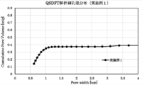
- 3 is a graph showing the pore size distribution of the activated carbon of Example 1 calculated by the QSDFT method.
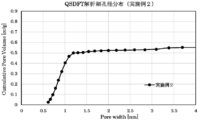
- 4 is a graph showing the pore size distribution of the activated carbon of Example 2 calculated by the QSDFT method.
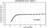
- 9 is a graph showing the pore size distribution of the activated carbon of Example 3 calculated by the QSDFT method.
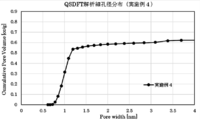
- 9 is a graph showing the pore size distribution of the activated carbon of Example 4 calculated by the QSDFT method.
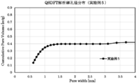
- 9 is a graph showing the pore size distribution of the activated carbon of Example 5 calculated by the QSDFT method.
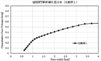
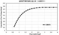
- 5 is a graph showing the pore size distribution of the activated carbon of Comparative Example 1 calculated by the QSDFT method.
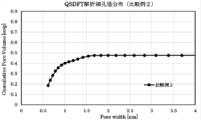
- 9 is a graph showing the pore size distribution of the activated carbon of Comparative Example 2 calculated by the QSDFT method.
- 9 is a graph showing the pore size distribution of the activated carbon of Comparative Example 3 calculated by the QSDFT method.
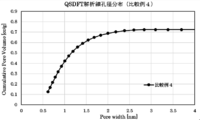
- 9 is a graph showing the pore size distribution of the activated carbon of Comparative Example 4 calculated by the QSDFT method.
- 11 is a graph showing the pore size distribution of the activated carbon of Comparative Example 5 calculated by the QSDFT method.
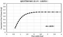
- 9 is a graph showing the pore size distribution of the activated carbon of Comparative Example 6 calculated by the QSDFT method.
- 9 is a graph showing the pore size distribution of the activated carbon of Comparative Example 7 calculated by the QSDFT method.
- the pore volume A having a pore diameter of 1.0 nm or less among the pore volumes calculated by the QSDFT method is 0.3 cc / g or more, and is calculated by the QSDFT method.
- the pore volume B having a pore diameter in the range of 3.0 nm to 3.5 nm is 0.009 cc / g or more.
- a pore volume having a pore diameter of 1.0 nm or less is specified as a specific volume, and a pore volume having a pore diameter of 3.0 nm or more and 3.5 nm or less is used. It is important that the volume be in a specific range.
- pores of 1.0 nm or less readily adsorb trihalomethane molecules
- pores of 3.0 nm or more and 3.5 nm or less have pores of trihalomethane molecules in addition to the adsorption of trihalomethane molecules.
- the activated carbon of the present invention iron (Fe) is selected as a metal to be contained in the activated carbon precursor, and CO 2 is selected and activated as a gas used when activating the activated carbon precursor.
- an activated carbon having a large pore volume with a pore diameter in the range of 3.0 nm or more and 3.5 nm or less can be obtained while maintaining a large pore volume with a pore diameter in the range of 1.0 nm or less. Therefore, even under a high SV, a high total trihalomethane filtration ability can be exhibited.
- the pore volume in a specific pore diameter range is calculated by the QSDFT method.
- the QSDFT method Quenched Solid Density Functional Method
- the QSDFT method is a pore size distribution from about 0.5 nm to about 40 nm for the analysis of the pore size of microporous and mesoporous carbon that is geometrically and chemically irregular. This is an analysis method that can calculate.
- the QSDFT method is a method in which the accuracy of the pore diameter distribution analysis has been greatly improved because the influence of the roughness and unevenness of the pore surface is clearly considered.
- a nitrogen adsorption isotherm is performed using “AUTOSORB-1-MP” manufactured by Quantachrome, and pore size distribution analysis is performed by a QSDFT method.
- a nitrogen desorption isotherm measured at a temperature of 77 K a specific pore size range is calculated by calculating a pore size distribution by applying N 2 at 77 K on carbon [slit pore, QSDFT equilibrium model] as a calculation model. The pore volume can be calculated.
- the activated carbon of the present invention has a pore volume A having a pore diameter of 1.0 nm or less in the pore volume calculated by the QSDFT method of 0.3 cc / g or more, and has a large superficial velocity (SV).
- the pore volume A is preferably 0.33 cc / g or more and 0.50 cc / g or less, and more preferably 0.35 cc / g or more and 0.30 cc / g or less, from the viewpoint of easily having a higher total trihalomethane filtration ability also in the water passing treatment. It is more preferably at most 45 cc / g.
- the pore volume A is preferably 0.35 cc / g or more and 0.50 cc / g or less, and more preferably 0.38 cc / g or more and 0.45 cc / g or less, from the viewpoint of further exhibiting the chloroform filtration ability. Is more preferred.
- the activated carbon of the present invention has a pore volume B of a pore diameter in a range of 3.0 nm to 3.5 nm of 0.009 cc / g or more in a pore volume calculated by the QSDFT method, and has a large superficial velocity.
- the pore volume B is preferably 0.009 cc / g or more and 0.025 cc / g or less, and 0.009 cc / g from the viewpoint of easily having a higher total trihalomethane filtration ability. g or more and 0.016 cc / g or less is more preferable.
- the pore volume A is preferably 0.009 cc / g or more and 0.025 cc / g or less, and 0.014 cc / g or more and 0.016 cc / g or less from the viewpoint of exhibiting more chloroform filtration ability. Is more preferred.
- the activated carbon of the present invention makes it easier to increase the pore volume A having a pore diameter in the range of 1.0 nm or less, and achieves a higher total trihalomethane filtration ability even in water treatment at a high superficial velocity (SV).
- the pore volume C having a pore diameter in the range of 2.0 nm or more and 3.0 nm or less in the pore volume calculated by the QSDFT method is preferably 0.05 cc / g or less.
- the conventional activated carbon as the pore volume of the mesopores is increased, the once activated pores having a pore diameter in the range of 1.0 nm or less are further promoted, and the pores have a pore diameter of 1.0 nm.
- the activated carbon of the present invention has a pore volume of 0.65 nm in the pore volume calculated by the QSDFT method from the viewpoint of easily having a higher total trihalomethane filtration ability even in a water passage treatment at a large superficial velocity (SV).
- the pore volume having a pore diameter in the following range is preferably from 0.03 cc / g to 0.25 cc / g.
- the pore volume of the pore diameter in the range of 0.65 nm or less is preferably 0.03 cc / g or more and 0.08 cc / g or less from the viewpoint of further exhibiting the chloroform filtration ability.
- the activated carbon of the present invention has a pore volume of 0.8 nm among pore volumes calculated by the QSDFT method from the viewpoint of easily having a higher total trihalomethane filtration ability even in water treatment at a high superficial velocity (SV).
- the pore volume having a pore diameter in the following range is from 0.03 cc / g to 0.40 cc / g, preferably from 0.15 cc / g to 0.40 cc / g.
- the pore volume of the pore diameter in the range of 0.8 nm or less is preferably 0.15 cc / g or more and 0.20 cc / g or less from the viewpoint of exhibiting the chloroform filtration ability more.
- the activated carbon of the present invention has 1.5 nm of the pore volume calculated by the QSDFT method from the viewpoint of easily having a higher total trihalomethane filtration ability even in the water flow treatment at a high superficial velocity (SV).
- the pore volume having a pore diameter in the following range is preferably from 0.3 cc / g to 0.6 cc / g, and more preferably from 0.3 cc / g to 0.53 cc / g.
- the pore volume of the pore diameter in the range of 1.5 nm or less is preferably 0.46 cc / g or more and 0.55 cc / g or less from the viewpoint of exhibiting the chloroform filtration ability more.
- the activated carbon of the present invention has 2.0 nm of the pore volume calculated by the QSDFT method from the viewpoint of making it easier to have a higher total trihalomethane filtration ability even in a water flow treatment at a large superficial velocity (SV).
- the pore volume having a pore diameter in the following range is preferably from 0.3 cc / g to 0.6 cc / g, and more preferably from 0.3 cc / g to 0.53 cc / g.
- the pore volume of the pore diameter in the range of 2.0 nm or less is preferably 0.46 cc / g or more and 0.55 cc / g or less from the viewpoint of exhibiting more chloroform filtering ability.
- the activated carbon of the present invention has 3.5 nm of the pore volume calculated by the QSDFT method from the viewpoint of easily having a higher total trihalomethane filtration ability even in the water passage treatment at a large superficial velocity (SV).
- the pore volume of the pore diameter in the above range is preferably 0.03 cc / g or less, more preferably 0.015 cc / g or less, and particularly preferably 0.001 cc / g or more and 0.015 cc / g or less.
- the pore volume of the pore diameter in the range of 3.5 nm or more is preferably 0.006 cc / g or more and 0.015 cc / g or less from the viewpoint of exhibiting the chloroform filtration ability more.
- the activated carbon of the present invention has 2.0 nm of the pore volume calculated by the QSDFT method from the viewpoint of making it easier to have a higher total trihalomethane filtration ability even in a water flow treatment at a large superficial velocity (SV).
- the pore volume of the pore diameter in the above range is preferably 0.08 cc / g or less, more preferably 0.01 cc / g or more and 0.05 cc / g or less.
- the pore volume of the pore diameter in the range of 2.0 nm or more is preferably 0.03 cc / g or more and 0.05 cc / g or less from the viewpoint of further exhibiting the chloroform filtration ability.
- the activated carbon of the present invention has a pore volume of 0.65 nm in the pore volume calculated by the QSDFT method from the viewpoint of easily having a higher total trihalomethane filtration ability even in a water flow treatment at a large superficial velocity (SV).
- the pore volume of the pore diameter in the range of not less than 1.0 nm and not more than 0.15 cc / g is preferably not more than 0.40 cc / g.
- the pore volume of the pore diameter in the range of 0.65 nm or more and 1.0 nm or less is preferably 0.33 cc / g or more and 0.40 cc / g or less from the viewpoint of further exhibiting the chloroform filtration ability. preferable.
- the activated carbon of the present invention preferably has a specific surface area (value measured by the BET method (one-point method) using nitrogen as a substance to be adsorbed) of about 500 to 1800 m 2 / g, more preferably 800 to 800 m 2 / g. About 1500 m 2 / g.
- the total pore volume of the activated carbon calculated by the QSDFT method is preferably about 0.33 to 1.50 cc / g, more preferably about 0.35 to 0.60 cc / g.
- the activated carbon of the present invention has a ratio of the fine pore volume A to the total fine pore volume (fine) in view of facilitating a higher total trihalomethane filtration ability even in a water flow treatment at a high superficial velocity (SV).
- (Pore volume A / total pore volume) is from 0.40 to 0.95, preferably from 0.60 to 0.89, more preferably from 0.70 to 0.85.
- the above ratio is preferably from 0.65 to 0.75 from the viewpoint of further exhibiting the chloroform filtration ability.
- the activated carbon of the present invention has a ratio (fineness) of the pore volume B to the total pore volume from the viewpoint of easily having a higher total trihalomethane filtration ability even in a water flow treatment at a high superficial velocity (SV).
- SV superficial velocity
- the activated carbon of the present invention has a ratio (fine) of the pore volume A and the pore volume B from the viewpoint of easily having a higher total trihalomethane filtration ability even in a water flow treatment at a high superficial velocity (SV).
- the pore volume B / pore volume A) is from 0.01 to 0.08, preferably from 0.02 to 0.05.
- the activated carbon of the present invention has a pore size calculated by the QSDFT method with respect to the total pore volume from the viewpoint of easily having a higher total trihalomethane filtration ability even in a water flow treatment at a large superficial velocity (SV).
- the ratio of the pore volume of the pore diameter in the range of 2.0 nm or less is 0.90 to 0.98. It is preferably mentioned, and more preferably 0.93 to 0.96. In addition, the above ratio may be more than 0.95 or 0.96 or more.
- the ratio is preferably from 0.92 to 0.94 from the viewpoint of further exhibiting the chloroform filtration ability.
- the activated carbon of the present invention has a pore size calculated by the QSDFT method with respect to the total pore volume from the viewpoint of easily having a higher total trihalomethane filtration ability even in a water flow treatment at a large superficial velocity (SV).
- the ratio of the pore volume of the pore diameter in the range of 2.0 nm or more is 0.02 to 0.10. And more preferably 0.04 to 0.07. Further, the ratio may be less than 0.05 or 0.04 or less.
- the above ratio is preferably from 0.06 to 0.08 from the viewpoint of further exhibiting the chloroform filtration ability.
- the activated carbon of the present invention has 2.0 nm of the pore volume calculated by the QSDFT method from the viewpoint of making it easier to have a higher total trihalomethane filtration ability even in a water flow treatment at a large superficial velocity (SV).
- Ratio of pore volume A having a pore diameter of 1.0 nm or less to pore volume having a pore diameter of the following range (pore volume A having a pore diameter of 1.0 nm or less / pore volume A of 2.0 nm or less)
- the pore volume having a pore diameter of 0.50 to 0.95 is mentioned, and preferably 0.70 to 0.89.
- the activated carbon of the present invention has a pore size calculated by the QSDFT method with respect to the total pore volume from the viewpoint of easily having a higher total trihalomethane filtration ability even in a water flow treatment at a large superficial velocity (SV).
- the ratio of the pore volume of the pore diameter in the range of 1.5 nm or less is 0.85 or more, 0.90 to 0.96 are more preferable.
- the above ratio is preferably from 0.90 to 0.92 from the viewpoint of further exhibiting the chloroform filtration ability.
- the main raw material of the activated carbon precursor (that is, the raw material from which the activated carbon of the present invention is derived) is not particularly limited.
- infusible or carbonized organic material phenol
- the material include infusible resins such as resins
- examples of the organic material include polyacrylonitrile, pitch, polyvinyl alcohol, and cellulose.
- the activated carbon of the present invention is preferably derived from pitch, and more preferably derived from coal pitch.
- the activated carbon of the present invention contains an iron compound as an activated carbon precursor in order to obtain the above-mentioned specific pore size distribution.
- the activated carbon of the present invention may contain simple iron and / or an iron compound derived from the iron compound contained in the activated carbon precursor.
- the ratio (total) of the mass of the simple substance of iron and the iron compound contained in the activated carbon to the total mass of the activated carbon of the present invention is, for example, 0.1 to 1.0% by mass, and 0.15 to 0%. 0.3% by mass.
- the above ratio is a ratio in terms of iron element (that is, iron content) measured by an ICP emission spectrometer (Model 715-ES manufactured by Varian).
- the activated carbon of the present invention can be washed after being activated. At that time, the concentration of the simple iron and / or iron compound present on the activated carbon surface can be lower than the concentration of the simple iron and / or iron compound existing inside the activated carbon. That is, the activated carbon of the present invention contains simple iron and / or an iron compound, and the concentration of the simple iron and the iron compound inside the activated carbon is higher than the concentrations of the simple iron and the iron compound on the surface of the activated carbon. Can be.
- the form of the activated carbon of the present invention is not particularly limited, and examples thereof include granular activated carbon, powdered activated carbon, and fibrous activated carbon. It is more preferable to use fibrous activated carbon from the viewpoints of workability when used after filtering and adsorption speed when used in a water purifier.
- the average fiber diameter of the fibrous activated carbon is preferably 30 ⁇ m or less, more preferably about 5 to 20 ⁇ m.
- the average fiber diameter of the fibrous activated carbon of the present invention is a value measured by an image processing fiber diameter measuring device (based on JIS K 1477).
- an integrated volume percentage D 50 measured by a laser diffraction / scattering method is 0.01 to 5 mm.
- the pore volume A having a pore diameter of 1.0 nm or less among the pore volumes calculated by the QSDFT method is 0.3 cc / g or more, and is calculated by the QSDFT method. Since the pore volume B having a pore diameter in the range of 3.0 nm to 3.5 nm in the pore volume is 0.009 cc / g or more, even in a water passage treatment at a high superficial velocity (SV), Activated carbon having high total trihalomethane filtration ability can be obtained.
- SV superficial velocity
- the total trihalomethane filtration capacity of the activated carbon of the present invention in the water treatment at a high superficial velocity (SV) includes, for example, 45 to 90 L / g in the case of SV 3000 h -1 , and preferably 60 to 80 L / g. No.
- the water temperature is controlled at 20 ° C. ⁇ 1 ° C., and water is passed through the activated carbon column at a superficial velocity of 3000 h ⁇ 1 .
- concentrations of the sample water and the filtered water are measured by a headspace method using a non-radiation source type electron capture detector (GC7000EN, manufactured by J-Science Laboratories).
- GC7000EN non-radiation source type electron capture detector
- the sample water is continuously passed until the total trihalomethane removal rate of the filtered water falls below 80%, and the flow rate (L / g) at a removal rate of 80% is defined as the total trihalomethane adsorption capacity of the activated carbon.
- the chloroform filtration capability of the activated carbon of the present invention in the water passage treatment at a high superficial velocity (SV) includes, for example, 45 to 90 L / g in the case of SV3000h- 1 , and 50 to 70 L / g. Preferred are mentioned.
- the chloroform filtration capacity (L / g) is measured by the following method. That is, the activated carbon is dried in a dryer at 105 ° C. for 2 hours or more, 3.0 g is collected, beaten with a mixer, and then filled in a glass column. A glass column having a diameter of 25 mm is used and packed so as to have a height of 41 mm. Prepare a sample water with a chloroform concentration of 60 ⁇ 12 ppb based on JIS-S-3201 “Test method for household water purifier”, control the water temperature at 20 ° C. ⁇ 1 ° C., and pass it through an activated carbon column at a superficial velocity of 3000 h ⁇ 1. Water.
- the concentrations of the sample water and the filtered water are measured by a headspace method using a non-radiation source type electron capture detector (GC7000EN, manufactured by J-Science Laboratories).
- GC7000EN non-radiation source type electron capture detector
- the sample water is continuously passed until the chloroform removal rate of the filtered water falls below 80%, and the flow rate (L / g) at the removal rate of 80% is defined as the chloroform adsorption capacity of the activated carbon.
- the method for producing activated carbon of the present invention includes a step of activating a activated carbon precursor containing 0.1 to 1.5% by mass of iron at a temperature of 900 to 1000 ° C. in an atmosphere having a CO 2 concentration of 90% by volume or more. Is preferred.
- Patent Document 2 also discloses an activated carbon precursor containing at least one metal component of Mg, Mn, Fe, Y, Pt and Gd in order to set the volume of pores having a pore diameter of 30 ° or more and less than 50 ° in a specific range.
- a method for activating a body under an atmosphere in which nitrogen and saturated steam are present is disclosed.
- the pore volume of a pore diameter of 1 nm or less is reduced in order to increase the volume of the mesopores, and the filtration capability of total trihalomethane under high superficial velocity conditions cannot be sufficiently exhibited. .
- an activated carbon precursor containing 0.1 to 1.5% by mass of iron is activated using an activation gas containing 90% by volume or more of CO 2 which reacts more slowly than steam.
- the main raw material of the activated carbon precursor is not particularly limited.
- an infusible or carbonized organic material an infusible resin such as a phenol resin, and the like can be used.
- the organic material include polyacrylonitrile, pitch, polyvinyl alcohol, and cellulose. From the viewpoint of the theoretical carbonization yield during carbonization, pitch is preferable, and among the pitches, coal pitch is particularly preferable.
- the iron content of the activated carbon precursor is preferably 0.5 to 1.0% by mass.
- Iron can be contained by mixing iron alone or an iron compound with a raw material.
- the iron compound include inorganic metal compounds such as metal oxides, metal hydroxides, metal halides, metal sulfates, and the like, salts of organic acids and metals such as acetic acid, and organic metal compounds containing iron as a constituent metal element. Is mentioned.
- the organic metal compound include metal acetylacetonate, an aromatic metal compound, and the like.
- an organometallic compound from the viewpoint of highly dispersing the metal in the activated carbon precursor and obtaining activated carbon having a high total trihalomethane filtration ability even in water passing treatment at a high superficial velocity (SV).
- a metal complex having a ⁇ -diketone compound as a ligand is more preferable.
- the ⁇ -diketone type compound include those having a structure represented by the following formulas (1) to (3), and specific examples include acetylacetone.
- the activation atmosphere has a CO 2 concentration of 90% by volume or more, preferably 95% by volume or more, more preferably 99% by volume or more.
- CO 2 when used as an activation gas, the reaction proceeds slowly. Therefore, the higher the CO 2 concentration, the easier it is to adjust the pore size distribution, and the easier it is to obtain the activated carbon of the present invention.
- the activation atmosphere temperature is usually about 900 to 1000 ° C., preferably about 900 to 980 ° C.
- the activation time may be adjusted so as to have a predetermined pore size distribution according to the main raw material of the activated carbon precursor, the content of the iron compound, the CO 2 concentration in the activation gas, and the like.
- a pitch having a softening point of 275 ° C. to 288 ° C. is used as the main raw material of the activated carbon precursor, and the content of the iron compound in the activated carbon precursor is 0.1 to 1.5 parts by mass, and the CO 2 concentration is Is 100% by volume
- the activation is performed at an activation atmosphere temperature of 900 to 1000 ° C. and an activation time of 20 to 70 minutes.
- Iron content (mass%) of activated carbon precursor (infusible pitch fiber)
- the pitch fiber was incinerated, the ash was dissolved in an acid, and the ratio of iron element as measured by an ICP emission spectrometer (Model 715-ES manufactured by Varian) was defined as the iron content.
- Pore volume (cc / g), specific surface area (m 2 / g), fiber diameter of fibrous activated carbon ( ⁇ m) The pore physical property values were measured from a nitrogen adsorption isotherm at 77 K using “AUTOSORB-1-MP” manufactured by Quantachrome. The specific surface area was calculated from the measurement point at a relative pressure of 0.1 by the BET method. The total pore volume and the pore volume in each pore diameter range described in Table 1 were determined by applying N 2 at 77K on carbon [slit pore, QSDFT equilibrium model] as a calculation model to the measured nitrogen desorption isotherm. It was analyzed by calculating the pore size distribution.
- the pore volume in each pore diameter range described in Table 1 is a read value of a graph showing the pore diameter distribution shown in FIGS. 1 to 11 or a value calculated from the read value. More specifically, the pore volume with a pore diameter of 0.65 nm or less is a reading of Cumulative Pore Volume (cc / g) when the horizontal axis Pore Width of the pore diameter distribution diagram is 0.65 nm.
- a pore volume with a pore size of 0.8 nm or less, a pore volume A with a pore size of 1.0 nm or less, a pore volume with a pore size of 1.5 nm or less, a pore volume with a pore size of 2.0 nm or less, a fine volume A pore volume with a pore size of 2.5 nm or less, a pore volume with a pore size of 3.0 nm or less, and a pore volume with a pore size of 3.5 nm or less were obtained.
- the pore volume B in the range of 3.0 to 3.5 nm was calculated by subtracting the pore volume of 3.0 nm or less from the pore volume of 3.5 nm or less.
- the pore volume C having a pore diameter in the range of 2.0 nm or more and 3.0 nm or less was calculated by subtracting the pore volume of 2.0 nm or less from the pore volume of 3.0 nm or less.
- the pore volume with a pore diameter of 3.5 nm or more was calculated by subtracting the pore volume with a pore diameter of 3.5 nm or less from the total pore volume obtained by the QSDFT method.
- the pore volume of the pore diameter in the range of 1.0 nm or more and 1.5 nm or less was calculated by subtracting the pore volume A of 1.0 nm or less from the pore volume of 1.5 nm or less.
- the pore volume of the pore diameter in the range of 1.0 nm or more and 2.0 nm or less was calculated by subtracting the pore volume A of 1.0 nm or less from the pore volume of 2.0 nm or less.
- the pore volume of the pore diameter in the range of 0.65 nm or more and 0.8 nm or less was calculated by subtracting the pore volume of the pore diameter of 0.65 nm or less from the pore volume of 0.8 nm or less.
- the pore volume of the pore diameter in the range of 0.65 nm or more and 1.0 nm or less was calculated by subtracting the pore volume of the pore diameter of 0.65 nm or less from the pore volume A of 1.0 nm or less.
- the pore volume of the pore diameter in the range of 0.8 nm or more and 1.5 nm or less was calculated by subtracting the pore volume of the pore diameter of 0.8 nm or less from the pore volume of 1.5 nm or less.
- the pore volume of the pore diameter in the range of 1.5 nm or more and 2.5 nm or less was calculated by subtracting the pore volume of the pore diameter of 1.5 nm or less from the pore volume of 2.5 nm or less.
- the pore volume with a pore size of 2.0 nm or more was calculated by subtracting the pore volume with a pore size of 2.0 nm or less from the total pore volume obtained by the QSDFT method.
- the pore volume with a pore diameter of 2.5 nm or more was calculated by subtracting the pore volume with a pore diameter of 2.5 nm or less from the total pore volume obtained by the QSDFT method.
- Fiber diameter of fibrous activated carbon ( ⁇ m) It was measured by an image processing fiber diameter measuring device (based on JIS K1277).
- Total trihalomethane filtration capacity (L / g) After drying the fibrous activated carbon with a dryer at 105 ° C. for 2 hours or more, 3.0 g was collected, beaten with a mixer, and filled in a glass column. The glass column used had a diameter of 25 mm and was packed to a height of 41 mm.
- Prepare a sample water having a concentration of 100 ⁇ 20 ppb in total trihalomethane (CHCl 3 : CHCl 2 Br: CHClBr 2 : CHBr 3 45: 30: 20: 5) based on JIS-S-3201 “Test method for household water purifier”. Then, the water temperature was controlled at 20 ° C.
- the concentrations of the sample water and the filtered water were measured by a headspace method using a non-radiation source type electron capture detector (GC7000EN, manufactured by J-Science Lab Co., Ltd.).
- GC7000EN non-radiation source type electron capture detector
- the sample water was continuously passed until the chloroform removal rate of the filtered water was less than 80%, and the flow rate (L / g) at the removal rate of 80% was taken as the chloroform adsorption capacity of the activated carbon.
- Example 1 As an organic material, a mixture of 0.9 parts by mass of tris (2,4-pentanedionato) iron (III) (metal species Fe) mixed with 100 parts by mass of granular coal pitch having a softening point of 280 ° C. is melted.
- the pitch fiber was supplied to an extruder, melt-mixed at a melting temperature of 320 ° C., and spun at a discharge rate of 16 g / min to obtain a pitch fiber.
- the obtained pitch fibers were heated in the air from room temperature to 354 ° C. at a rate of 1 to 30 ° C./min for 54 minutes to perform infusibilization treatment, and an activated carbon precursor as infusible pitch fibers was obtained.
- the content of iron (Fe) was 0.11% by mass.
- the activated carbon precursor thus obtained was activated by continuously introducing a gas having a CO 2 concentration of 100% by volume into the activation furnace and performing a heat treatment at an atmosphere temperature of 950 ° C. for 25 minutes to obtain the activated carbon of Example 1.
- the obtained activated carbon has a pore volume A of a pore diameter in a range of 1.0 nm or less of 0.350 cc / g, and a pore volume B of a pore diameter in a range of 3.0 nm to 3.5 nm of 0.012 cc / g. g, the iron content was 0.184% by mass, and the average fiber diameter was 13.9 ⁇ m.
- Example 2 As an organic material, a mixture of 0.9 parts by mass of tris (2,4-pentanedionato) iron (III) (metal species Fe) mixed with 100 parts by mass of granular coal pitch having a softening point of 280 ° C. is melted.
- the pitch fiber was supplied to an extruder, melt-mixed at a melting temperature of 320 ° C., and spun at a discharge rate of 16 g / min to obtain a pitch fiber.
- the obtained pitch fibers were heated in the air from room temperature to 354 ° C. at a rate of 1 to 30 ° C./min for 54 minutes to perform infusibilization treatment, and an activated carbon precursor as infusible pitch fibers was obtained.
- the content of iron (Fe) was 0.11% by mass.
- the activated carbon precursor thus obtained was activated by continuously introducing a gas having a CO 2 concentration of 100% by volume into the activation furnace and performing a heat treatment at an atmosphere temperature of 950 ° C. for 40 minutes to obtain the activated carbon of Example 2.
- the obtained activated carbon has a pore volume A of 0.396 cc / g in a pore diameter of 1.0 nm or less and a pore volume B of 0.016 cc / g in a pore diameter of 3.0 nm or more and 3.5 nm or less.
- the iron content was 0.251% by mass, and the average fiber diameter was 13.6 ⁇ m.
- Example 3 As an organic material, a mixture of 0.7 parts by mass of tris (2,4-pentanedionato) iron (III) (metal species Fe) mixed with 100 parts by mass of granular coal pitch having a softening point of 280 ° C. is melted.
- the pitch fiber was supplied to an extruder, melt-mixed at a melting temperature of 320 ° C., and spun at a discharge rate of 16 g / min to obtain a pitch fiber.
- the obtained pitch fibers were heated in the air from room temperature to 354 ° C. at a rate of 1 to 30 ° C./min for 54 minutes to perform infusibilization treatment, and an activated carbon precursor as infusible pitch fibers was obtained.
- the content of iron (Fe) was 0.094% by mass.
- the activated carbon precursor thus obtained was activated by continuously introducing a gas having a CO 2 concentration of 100% by volume into the activation furnace and performing a heat treatment at an atmosphere temperature of 950 ° C. for 40 minutes to obtain the activated carbon of Example 3.
- the obtained activated carbon has a pore volume A having a pore diameter in the range of 1.0 nm or less of 0.356 cc / g, and a pore volume B having a pore diameter in the range of 3.0 nm to 3.5 nm of 0.009 cc / g. g, the content of iron was 0.184% by mass, and the average fiber diameter was 13.8 ⁇ m.
- Example 4 As an organic material, a mixture of 0.9 parts by mass of tris (2,4-pentanedionato) iron (III) (metal species Fe) mixed with 100 parts by mass of granular coal pitch having a softening point of 280 ° C. is melted.
- the pitch fiber was supplied to an extruder, melt-mixed at a melting temperature of 320 ° C., and spun at a discharge rate of 16 g / min to obtain a pitch fiber.
- the obtained pitch fibers were heated in the air from room temperature to 354 ° C. at a rate of 1 to 30 ° C./min for 54 minutes to perform infusibilization treatment, and an activated carbon precursor as infusible pitch fibers was obtained.
- the content of iron (Fe) was 0.11% by mass.
- the activated carbon precursor thus obtained was activated by continuously introducing a gas having a CO 2 concentration of 100% by volume into the activation furnace and performing a heat treatment at an atmosphere temperature of 950 ° C. for 50 minutes to obtain the activated carbon of Example 3.
- the obtained activated carbon has a pore volume A having a pore diameter in a range of 1.0 nm or less of 0.303 cc / g, and a pore volume B having a pore diameter in a range of 3.0 nm to 3.5 nm of 0.018 cc / g. g, the iron content was 0.318% by mass, and the average fiber diameter was 13.2 ⁇ m.
- Example 5 As an organic material, a mixture of 0.9 parts by mass of tris (2,4-pentanedionato) iron (III) (metal species Fe) mixed with 100 parts by mass of granular coal pitch having a softening point of 280 ° C. is melted.
- the pitch fibers were supplied to an extruder, melt-mixed at a melting temperature of 325 ° C., and spun at a discharge rate of 16 g / min.
- the obtained pitch fiber was heated stepwise to 349 ° C. in the air and held for a total of 75 minutes to perform infusibilization treatment, thereby obtaining an activated carbon precursor as infusible pitch fiber.
- the content of iron (Fe) was 0.10% by mass.
- the activated carbon precursor thus obtained was activated by continuously introducing a gas having a CO 2 concentration of 100% by volume into the activation furnace and performing a heat treatment at an atmosphere temperature of 950 ° C. for 40 minutes to obtain the activated carbon of Example 5.
- the obtained activated carbon has a pore volume A having a pore diameter in the range of 1.0 nm or less of 0.346 cc / g, and a pore volume B having a pore diameter in the range of 3.0 nm to 3.5 nm of 0.019 cc / g. g, the iron content was 0.235% by mass, and the average fiber diameter was 13.4 ⁇ m.
- Example 1 A test simulating Example 5 of Patent Document 2 was performed. Specifically, a mixture of 1.3 parts by mass of trisacetylacetonatoittrium and 100 parts by mass of a granular coal pitch having a softening point of 280 ° C. as an organic material is supplied to a melt extruder, and a melting temperature of 320 ° C. , And spinning was performed at a discharge rate of 20 g / min to obtain pitch fibers. The obtained pitch fibers were heated in the air from room temperature to 354 ° C. at a rate of 1 to 30 ° C./min for 54 minutes to perform infusibilization treatment, and an activated carbon precursor as infusible pitch fibers was obtained. In the activated carbon precursor, the content of yttrium was 0.25% by mass.
- the activated carbon precursor thus obtained was activated by continuously introducing a gas having an H 2 O concentration of 100% by volume into the activation furnace and performing a heat treatment at an ambient temperature of 900 ° C. for 20 minutes to obtain the activated carbon of Comparative Example 1. Obtained.
- the obtained activated carbon has a pore volume A having a pore diameter in the range of 1.0 nm or less of 0.241 cc / g, and a pore volume B having a pore diameter in the range of 3.0 nm to 3.5 nm of 0.042 cc / g. g, the content of yttrium was 0.66% by mass, and the average fiber diameter was 16.5 ⁇ m.
- the activated carbon precursor thus obtained was activated by continuously introducing a gas having an H 2 O concentration of 100% by volume into the activation furnace and performing a heat treatment at an atmosphere temperature of 875 ° C. for 40 minutes to obtain the activated carbon of Comparative Example 2. Obtained.
- the obtained activated carbon has a pore volume A having a pore diameter in a range of 1.0 nm or less of 0.401 cc / g and a pore volume B of a pore diameter in a range of 3.0 nm to 3.5 nm of 0.000 cc / g. g, the iron content was 0% by mass, and the average fiber diameter was 16.7 ⁇ m.
- the activated carbon precursor thus obtained was activated by continuously introducing a gas having a CO 2 concentration of 100% by volume into the activation furnace and performing a heat treatment at an atmosphere temperature of 950 ° C. for 60 minutes to obtain an activated carbon of Comparative Example 3.
- the obtained activated carbon has a pore volume A having a pore diameter in a range of 1.0 nm or less of 0.311 cc / g and a pore volume B of a pore diameter in a range of 3.0 nm to 3.5 nm of 0.000 cc / g. g, the iron content was 0% by mass, and the average fiber diameter was 18.5 ⁇ m.
- the obtained activated carbon precursor was activated by continuously introducing a gas having a CO 2 concentration of 100% by volume into the activation furnace and heat-treating it at an atmosphere temperature of 950 ° C. for 67 minutes to obtain the activated carbon of Comparative Example 4.
- the obtained activated carbon has a pore volume A having a pore diameter in a range of 1.0 nm or less of 0.418 cc / g and a pore volume B of a pore diameter in a range of 3.0 nm to 3.5 nm of 0.000 cc / g. g, the content of yttrium was 0.17% by mass, and the average fiber diameter was 16.8 ⁇ m.
- the activated carbon precursor thus obtained was activated by continuously introducing a gas having a CO 2 concentration of 100% by volume into an activation furnace and performing a heat treatment at an atmosphere temperature of 950 ° C. for 70 minutes to obtain an activated carbon of Comparative Example 5.
- the obtained activated carbon has a pore volume A of a pore diameter in a range of 1.0 nm or less of 0.431 cc / g, and a pore volume B of a pore diameter in a range of 3.0 nm to 3.5 nm of 0.000 cc / g. g, the content of yttrium was 0.18% by mass, and the average fiber diameter was 16.8 ⁇ m.
- the activated carbon precursor thus obtained was activated by continuously introducing a gas having a CO 2 concentration of 100% by volume into an activation furnace and performing heat treatment at an atmosphere temperature of 950 ° C. for 60 minutes to obtain an activated carbon of Comparative Example 6.
- the obtained activated carbon has a pore volume A having a pore diameter of 1.0 nm or less of 0.429 cc / g and a pore volume B of a pore diameter ranging from 3.0 nm to 3.5 nm of 0.000 cc / g. g, the content of yttrium was 0.15% by mass, and the fiber diameter was 18.2 ⁇ m.
- Comparative Example 7 As an organic material, a mixture obtained by mixing 1.0 part by mass of trisacetylacetonatoittrium with 100 parts by mass of granular coal pitch having a softening point of 280 ° C. is supplied to a melt extruder and melt-mixed at a melting temperature of 320 ° C. By spinning at a discharge rate of 19 g / min, pitch fibers were obtained. The obtained pitch fibers were heated in the air from room temperature to 354 ° C. at a rate of 1 to 30 ° C./min for 54 minutes to perform infusibilization treatment, and an activated carbon precursor as infusible pitch fibers was obtained. In the activated carbon precursor, the content of yttrium was 0.16% by mass.
- the activated carbon precursor thus obtained was activated by continuously introducing a gas having a CO 2 concentration of 50% by volume and a H 2 O concentration of 50% by volume into an activation furnace and heat-treating it at an atmosphere temperature of 950 ° C. for 20 minutes.
- the activated carbon of Comparative Example 7 was obtained.
- the obtained activated carbon has a pore volume A having a pore diameter in a range of 1.0 nm or less of 0.255 cc / g, and a pore volume B having a pore diameter in a range of 3.0 nm to 3.5 nm of 0.034 cc / g. g, the content of yttrium was 0.46% by mass, and the average fiber diameter was 14.6 ⁇ m.
- the pore volume A having a pore diameter in the range of 1.0 nm or less was 0.3 cc / g or more, and the activated carbon was measured by the QSDFT method. Since the calculated pore volume has a pore volume B of a pore diameter in the range of 3.0 nm to 3.5 nm of 0.009 cc / g or more, water flow at a high superficial velocity (SV) is achieved. In the treatment, activated carbon having high total trihalomethane filtration ability could be obtained.
- the pore volume A having a pore diameter of 1.0 nm or less was less than 0.3 cc / g.
- the total trihalomethane filtration ability was inferior.
- the pore volume B having a pore diameter in the range of 3.0 nm to 3.5 nm was less than 0.009 cc / g among the pore volumes calculated by the QSDFT method. Therefore, the total trihalomethane filtration ability was inferior.
Landscapes
- Chemical & Material Sciences (AREA)
- Organic Chemistry (AREA)
- Chemical Kinetics & Catalysis (AREA)
- Analytical Chemistry (AREA)
- Inorganic Chemistry (AREA)
- Engineering & Computer Science (AREA)
- Water Supply & Treatment (AREA)
- Life Sciences & Earth Sciences (AREA)
- Environmental & Geological Engineering (AREA)
- Hydrology & Water Resources (AREA)
- Nanotechnology (AREA)
- General Chemical & Material Sciences (AREA)
- Textile Engineering (AREA)
- Solid-Sorbent Or Filter-Aiding Compositions (AREA)
- Carbon And Carbon Compounds (AREA)
- Water Treatment By Sorption (AREA)
- Inorganic Fibers (AREA)
Abstract
高い空塔速度(SV)での通水処理においても、高い総トリハロメタンろ過能力を有する活性炭を提供する 本発明の活性炭は、QSDFT法によって算出される細孔容積のうち、1.0nm以下の範囲の細孔径の細孔容積Aが0.3cc/g以上であり、 かつ、QSDFT法によって算出される細孔容積のうち、3.0nm以上3.5nm以下の範囲の細孔径の細孔容積Bが0.009cc/g以上である。
Description
本発明は、活性炭に関し、特に高空塔速度下におけるトリハロメタンのろ過能力に優れた、活性炭に関する。
従来、飲料用に供される水道水などには、殺菌を目的として塩素が添加されている。しかしながら、水道水中に含まれる塩素は、水道水中に含まれる有機物と反応して、有機ハロゲン系化合物を生成する。例えば、天然有機物であるフミン質が水道水中において塩素と反応すると、発がん性物質であるトリハロメタンを生成することが知られている。そして、水道水中に含まれるこれらの有機ハロゲン系化合物のろ過能力に優れた活性炭が提案されている。
有機ハロゲン系化合物のろ過能力に優れた活性炭として、例えば、細孔径が100Å(10nm)以下の細孔容積に対する、細孔径20Å~100Å(2nm~10nm)の細孔容積比率が5~50%であり、細孔径10Å(1nm)以下の細孔容積比率が45%以上である多孔質炭素を含有する吸着剤が知られている(例えば、特許文献1参照。)。該吸着剤において、細孔径が100Å以下の細孔容積に対して、細孔径20Å~100Åの細孔容積比率を5~50%とするのは、比較的大きな細孔の割合を高めて、動的吸着力を高めるためである。一方、該吸着剤においては、静的吸着力である平衡吸着量を高める必要もあることから、静的平衡吸着量に有効な細孔径10Å以下の細孔容積比率を45%以上とすることが開示されている。そして、該吸着剤は、このような構成とすることによって、静的吸着力と動的吸着力とを両立することができるとされている。
また、77.4Kにおける窒素吸着等温線よりBJH法で求めた細孔径分布において細孔直径30Å以上50Å未満の範囲のメソ細孔容積が0.02~0.40cc/gであり、かつ、全細孔容積に対する上記範囲のメソ細孔容積の割合が5~45%である活性炭が知られている(例えば、特許文献2参照)。該活性炭によれば、かかる範囲内に上記メソ細孔(直径2~50nmの細孔)容積及び上記割合を制御することによって、各種の被吸着物質(特にトリハロメタン類)の吸着に適した材料とすることができるとされている。
近年、このような活性炭を含む浄水フィルターには、高い総トリハロメタンろ過能力が求められている。例えば、浄水フィルターには、JIS S3201の「揮発性有機化合物のろ過能力試験」における総トリハロメタンの総ろ過水量(総トリハロメタンの除去率が80%に低下するまでの水量)が多いことが要求されてきている。該総ろ過水量が多いほど、浄水フィルターの使用可能期間(取替え期間)が長くなる。
加えて、浄水フィルターが水栓一体型浄水器用である場合などには、浄水フィルターは小型化する必要がある。浄水フィルターが小型になると、空塔速度(SV)が大きくなり、高い総トリハロメタンろ過能力を維持することが難しくなる。
本発明者等が検討した結果、特許文献1及び2に開示された活性炭は、SVが1000h-1の条件で評価されているところ、高い空塔速度(例えばSVが3000h-1程度)の条件下では、総トリハロメタンのろ過能力が十分発揮できないという問題があることが判明した。
本発明は、上記問題を解決し、高い空塔速度(SV)での通水処理においても、高い総トリハロメタンろ過能力を有する活性炭及びその製造方法を提供することを主な目的とする。
トリハロメタン分子は1.0nm以下の細孔に吸着しやすいと考えられる。しかしながら、本発明者等は、高SV下において総トリハロメタン分子のろ過を検討する場合には、トリハロメタン分子が細孔内に拡散する速度も重要な要素であると考えた。そこで、本発明者らはこれらの観点から検討を重ね、活性炭の細孔径及びその細孔容積を制御し、1.0nm以下の細孔径の細孔容積を特定の範囲とし、且つ3.0nm以上3.5nm以下の細孔径の細孔容積を特定範囲のものとすることで、高SV下においても高い総トリハロメタンろ過能力を有することを見出した。
例えば、特許文献1に開示された発明は、メソ孔のうちでも広範な細孔径範囲である2~10nmの細孔容積を制御することにより動的吸着力を高めることを図っている。しかし、該発明では、例えば3000h-1のような高いSV下でのろ過能力を向上すること、及び、1.0nm以下の範囲の細孔径の細孔容積を特定範囲のものとし、且つ、3.0nm以上3.5nm以下の範囲の細孔径の細孔容積を制御することは検討されていない。実際、同文献に実施例として具体的に開示された活性炭は、2~10nmの範囲の細孔径を発達させているものの、1nm以下の細孔径の細孔容積が小さくなっており、高い空塔速度の条件下での総トリハロメタンのろ過能力が十分発揮できない。
また、例えば、特許文献2に開示された発明は、比較的大きい細孔径3~5nmの範囲の細孔容積を制御することが開示されている。また、制御する方法として、Mg、Mn、Fe、Y、Pt及びGdの少なくとも1種の金属成分を0.01~5重量%含有するピッチを活性炭前駆体として用い、当該前駆体を不融化処理又は炭素化処理し、賦活処理する方法において、上記金属成分の種類を変えることによって、得られる活性炭のメソ細孔モード直径を制御することが開示されている。さらに、具体的に実施可能な態様としては、活性炭前駆体に金属を含有させ、水蒸気賦活をおこなう方法が開示されている。しかし、該発明においても、例えば3000h-1のような高いSV下でのろ過能力を向上すること、及び、1.0nm以下の範囲の細孔径の細孔容積を特定範囲のものとし、且つ、3.0nm以上3.5nm以下の範囲の細孔径の細孔容積を制御することは検討されていない。そして、本発明者等の検討によれば、特許文献2に実施例として具体的に開示された方法では、比較的大きい細孔径3~5nmの範囲の細孔容積は大きくすることができるものの、細孔径1nm以下の範囲の細孔容積を十分に大きいものとすることができず、高い空塔速度の条件下での総トリハロメタンのろ過能力が十分発揮できないことが判明した。
そして、本発明者等は、さらに検討し、活性炭前駆体に含有させる金属として鉄(Fe)を選択し、さらに該活性炭前駆体を賦活する際に用いるガスとしてCO2を選択して、賦活することにより、初めて、1.0nm以下の範囲の細孔径の細孔容積を大きくしたまま、且つ、3.0nm以上3.5nm以下の範囲の細孔径の細孔容積を大きくした活性炭が得られること、該活性炭が高SV下においても高い総トリハロメタンろ過能力を有すること、を見出した。
本発明は、これらの知見に基づいて、さらに検討を重ねることにより完成された発明である。
すなわち、本発明は、下記に掲げる態様の発明を提供する。
項1. QSDFT法によって算出される細孔容積のうち、1.0nm以下の範囲の細孔径の細孔容積Aが0.3cc/g以上であり、
かつ、QSDFT法によって算出される細孔容積のうち、3.0nm以上3.5nm以下の範囲の細孔径の細孔容積Bが0.009cc/g以上である、活性炭。
項2. QSDFT法によって算出される細孔容積のうち、2.0nm以上3.0nm以下の範囲の細孔径の細孔容積Cが0.05cc/g以下である、項1に記載の活性炭。
項3. QSDFT法によって算出される活性炭の全細孔容積(cc/g)に対する、QSDFT法によって算出される細孔容積のうち、1.5nm以下の範囲の細孔径の細孔容積(cc/g)の割合が0.85以上である、項1又は2に記載の活性炭。
項4. 比表面積が500~1800m2/gである、項1~3のいずれか1項に記載の活性炭。
項5. 総トリハロメタンろ過能力が45L/g以上である、項1~4のいずれか1項に記載の活性炭。
項6. 前記活性炭が繊維状活性炭である、項1~5のいずれか1項に記載の活性炭。
項7. 鉄を0.1~1.5質量%含む活性炭前駆体を、CO2濃度が90容積%以上の雰囲気下、温度900~1000℃で賦活する工程を含む、項1~6のいずれか1項に記載の活性炭の製造方法。
項1. QSDFT法によって算出される細孔容積のうち、1.0nm以下の範囲の細孔径の細孔容積Aが0.3cc/g以上であり、
かつ、QSDFT法によって算出される細孔容積のうち、3.0nm以上3.5nm以下の範囲の細孔径の細孔容積Bが0.009cc/g以上である、活性炭。
項2. QSDFT法によって算出される細孔容積のうち、2.0nm以上3.0nm以下の範囲の細孔径の細孔容積Cが0.05cc/g以下である、項1に記載の活性炭。
項3. QSDFT法によって算出される活性炭の全細孔容積(cc/g)に対する、QSDFT法によって算出される細孔容積のうち、1.5nm以下の範囲の細孔径の細孔容積(cc/g)の割合が0.85以上である、項1又は2に記載の活性炭。
項4. 比表面積が500~1800m2/gである、項1~3のいずれか1項に記載の活性炭。
項5. 総トリハロメタンろ過能力が45L/g以上である、項1~4のいずれか1項に記載の活性炭。
項6. 前記活性炭が繊維状活性炭である、項1~5のいずれか1項に記載の活性炭。
項7. 鉄を0.1~1.5質量%含む活性炭前駆体を、CO2濃度が90容積%以上の雰囲気下、温度900~1000℃で賦活する工程を含む、項1~6のいずれか1項に記載の活性炭の製造方法。
本発明の活性炭によれば、QSDFT法によって算出される細孔容積のうち、1.0nm以下の範囲の細孔径の細孔容積Aが0.3cc/g以上であり、かつ、QSDFT法によって算出される細孔容積のうち、3.0nm以上3.5nm以下の範囲の細孔径の細孔容積Bが0.009cc/g以上であることから、大きな空塔速度(SV)での通水処理においても、高い総トリハロメタンろ過能力を有する活性炭を得ることができる。
以下、本発明の活性炭について詳細に説明する。
本発明の活性炭は、QSDFT法によって算出される細孔容積のうち、1.0nm以下の範囲の細孔径の細孔容積Aが0.3cc/g以上であり、かつ、QSDFT法によって算出される細孔容積のうち、3.0nm以上3.5nm以下の範囲の細孔径の細孔容積Bが0.009cc/g以上である。
高SV下でも高い総トリハロメタンろ過能力を有するものとするには、1.0nm以下の範囲の細孔径の細孔容積を特定範囲とし、且つ3.0nm以上3.5nm以下の細孔径の細孔容積を特定範囲とすることが重要である。本発明者等が検討したところ、1.0nm以下の細孔はトリハロメタン分子を吸着しやすく、3.0nm以上3.5nm以下の細孔はトリハロメタン分子の吸着の他にもトリハロメタン分子の細孔内への拡散にも寄与すると考えられる。そして、本発明者等が検討を重ねたところ、従来技術は、3.0nm以上3.5nm以下の細孔径の細孔容積を大きくしようとすると、1.0nm以下の細孔径の細孔容積が小さくなってしまうという問題があった。すなわち、前述した、特許文献1及び2に開示された活性炭は、メソ細孔を大きくしようとしているが、一方で、1.0nm以下の細孔径の細孔容積が小さくなってしまい、これに起因して高SV下において高い総トリハロメタンろ過能力を十分発揮できないことが明らかとなった。
一方、本発明の活性炭によれば、活性炭前駆体に含有させる金属として鉄(Fe)を選択し、さらに該活性炭前駆体を賦活する際に用いるガスとしてCO2を選択して、賦活することにより、初めて、1.0nm以下の範囲の細孔径の細孔容積を大きくしたまま、且つ、3.0nm以上3.5nm以下の範囲の細孔径の細孔容積を大きくした活性炭が得られ、これにより、高SV下においても高い総トリハロメタンろ過能力を発揮できるのである。
本発明において、特定の細孔径範囲の細孔容積は、QSDFT法によって算出されるものである。QSDFT法(急冷固体密度汎関数法)とは、幾何学的・化学的に不規則なミクロポーラス・メソポーラスな炭素の細孔径解析を対象とした、約0.5nm~約40nmまでの細孔径分布の計算ができる解析手法である。QSDFT法では、細孔表面の粗さと不均一性による影響が明瞭に考慮されているため、細孔径分布解析の正確さが大幅に向上した手法である。本発明においては、Quantachrome社製「AUTOSORB-1-MP」を用いて窒素吸着等温線の測定、及びQSDFT法による細孔径分布解析をおこなう。77Kの温度において測定した窒素の脱着等温線に対し、Calculation modelとしてN2 at 77K on carbon[slit pore,QSDFT equilibrium model]を適用して細孔径分布を計算することで、特定の細孔径範囲の細孔容積を算出することができる。
本発明の活性炭は、QSDFT法によって算出される細孔容積のうち、1.0nm以下の範囲の細孔径の細孔容積Aが0.3cc/g以上であり、大きな空塔速度(SV)での通水処理においても、より高い総トリハロメタンろ過能力を有しやすくする観点から、当該細孔容積Aは0.33cc/g以上0.50cc/g以下が好ましく、0.35cc/g以上0.45cc/g以下がより好ましい。また、総トリハロメタンの中でも、クロロホルムろ過能力をより発揮させる観点から、当該細孔容積Aは0.35cc/g以上0.50cc/g以下が好ましく、0.38cc/g以上0.45cc/g以下がより好ましい。
本発明の活性炭は、QSDFT法によって算出される細孔容積のうち、3.0nm以上3.5nm以下の範囲の細孔径の細孔容積Bが0.009cc/g以上であり、大きな空塔速度(SV)での通水処理においても、より高い総トリハロメタンろ過能力を有しやすくする観点から、当該細孔容積Bは0.009cc/g以上0.025cc/g以下が好ましく、0.009cc/g以上0.016cc/g以下がより好ましい。また、総トリハロメタンの中でも、クロロホルムろ過能力をより発揮させる観点から、当該細孔容積Aは0.009cc/g以上0.025cc/g以下が好ましく、0.014cc/g以上0.016cc/g以下がより好ましい。
本発明の活性炭は、1.0nm以下の範囲の細孔径の細孔容積Aをより大きくしやすくして、大きな空塔速度(SV)での通水処理においても、より高い総トリハロメタンろ過能力を有しやすくする観点から、QSDFT法によって算出される細孔容積のうち、2.0nm以上3.0nm以下の範囲の細孔径の細孔容積Cが0.05cc/g以下であることが好ましい。従来の活性炭では、メソ細孔の細孔容積を大きくしようとするにつれて、一旦生じた1.0nm以下の範囲の細孔径の細孔のさらなる賦活が進み、当該細孔が細孔径1.0nmを超えるもの、例えば、2.0nm以上3.0nm以下の範囲の細孔径まで発達し、結果1.0nm以下の範囲の細孔径の細孔容積Aが減少する。従って、2.0nm以上3.0nm以下の範囲の細孔径の細孔容積Cが0.05cc/g以下とすることにより、一度生じた1.0nm以下の範囲の細孔径の細孔の細孔径が広がることを抑制でき、1.0nm以下の範囲の細孔径の細孔容積Aをより大きくすることができる。上記した細孔分布とするには、活性炭前駆体に含有させる金属として鉄(Fe)を選択し、さらに該活性炭前駆体を賦活する際に用いるガスとしてCO2を選択して、賦活することが挙げられる。
本発明の活性炭は、大きな空塔速度(SV)での通水処理においても、より高い総トリハロメタンろ過能力を有しやすくする観点から、QSDFT法によって算出される細孔容積のうち、0.65nm以下の範囲の細孔径の細孔容積は、0.03cc/g以上0.25cc/g以下が好ましい。また、総トリハロメタンの中でも、クロロホルムろ過能力をより発揮させる観点から、上記0.65nm以下の範囲の細孔径の細孔容積は、0.03cc/g以上0.08cc/g以下が好ましい。
本発明の活性炭は、大きな空塔速度(SV)での通水処理においても、より高い総トリハロメタンろ過能力を有しやすくする観点から、QSDFT法によって算出される細孔容積のうち、0.8nm以下の範囲の細孔径の細孔容積は、0.03cc/g以上0.40cc/g以下が挙げられ、0.15cc/g以上0.40cc/g以下が好ましい。また、総トリハロメタンの中でも、クロロホルムろ過能力をより発揮させる観点から、上記0.8nm以下の範囲の細孔径の細孔容積は、0.15cc/g以上0.20cc/g以下が好ましい。
本発明の活性炭は、大きな空塔速度(SV)での通水処理においても、より高い総トリハロメタンろ過能力を有しやすくする観点から、QSDFT法によって算出される細孔容積のうち、1.5nm以下の範囲の細孔径の細孔容積は、0.3cc/g以上0.6cc/g以下が好ましく、0.3cc/g以上0.53cc/g以下がより好ましい。また、総トリハロメタンの中でも、クロロホルムろ過能力をより発揮させる観点から、上記1.5nm以下の範囲の細孔径の細孔容積は、0.46cc/g以上0.55cc/g以下が好ましい。
本発明の活性炭は、大きな空塔速度(SV)での通水処理においても、より高い総トリハロメタンろ過能力を有しやすくする観点から、QSDFT法によって算出される細孔容積のうち、2.0nm以下の範囲の細孔径の細孔容積は、0.3cc/g以上0.6cc/g以下が好ましく、0.3cc/g以上0.53cc/g以下がより好ましい。また、総トリハロメタンの中でも、クロロホルムろ過能力をより発揮させる観点から、上記2.0nm以下の範囲の細孔径の細孔容積は、0.46cc/g以上0.55cc/g以下が好ましい。
本発明の活性炭は、大きな空塔速度(SV)での通水処理においても、より高い総トリハロメタンろ過能力を有しやすくする観点から、QSDFT法によって算出される細孔容積のうち、3.5nm以上の範囲の細孔径の細孔容積は、0.03cc/g以下が好ましく、0.015cc/g以下がより好ましく、0.001cc/g以上0.015cc/g以下が特に好ましい。また、総トリハロメタンの中でも、クロロホルムろ過能力をより発揮させる観点から、上記3.5nm以上の範囲の細孔径の細孔容積は、0.006cc/g以上0.015cc/g以下が好ましい。
本発明の活性炭は、大きな空塔速度(SV)での通水処理においても、より高い総トリハロメタンろ過能力を有しやすくする観点から、QSDFT法によって算出される細孔容積のうち、2.0nm以上の範囲の細孔径の細孔容積は、0.08cc/g以下が好ましく、0.01cc/g以上0.05cc/g以下がより好ましい。また、総トリハロメタンの中でも、クロロホルムろ過能力をより発揮させる観点から、上記2.0nm以上の範囲の細孔径の細孔容積は、0.03cc/g以上0.05cc/g以下が好ましい。
本発明の活性炭は、大きな空塔速度(SV)での通水処理においても、より高い総トリハロメタンろ過能力を有しやすくする観点から、QSDFT法によって算出される細孔容積のうち、0.65nm以上1.0nm以下の範囲の細孔径の細孔容積は、0.15cc/g以上0.40cc/g以下が好ましい。また、総トリハロメタンの中でも、クロロホルムろ過能力をより発揮させる観点から、上記0.65nm以上1.0nm以下の範囲の細孔径の細孔容積は、0.33cc/g以上0.40cc/g以下が好ましい。
本発明の活性炭は、活性炭の比表面積(窒素を被吸着物質として用いたBET法(1点法)により測定される値)としては、好ましくは500~1800m2/g程度、より好ましくは800~1500m2/g程度が挙げられる。また、QSDFT法によって算出される活性炭の全細孔容積としては、好ましくは0.33~1.50cc/g程度、より好ましくは0.35~0.60cc/g程度が挙げられる。
本発明の活性炭は、大きな空塔速度(SV)での通水処理においても、より高い総トリハロメタンろ過能力を有しやすくする観点から、前記全細孔容積に対する前記細孔容積Aの割合(細孔容積A/全細孔容積)は、0.40~0.95が挙げられ、0.60~0.89が好ましく挙げられ、0.70~0.85がより好ましく挙げられる。また、総トリハロメタンの中でも、クロロホルムろ過能力をより発揮させる観点から、上記割合は、0.65~0.75が好ましく挙げられる。
本発明の活性炭は、大きな空塔速度(SV)での通水処理においても、より高い総トリハロメタンろ過能力を有しやすくする観点から、前記全細孔容積に対する前記細孔容積Bの割合(細孔容積B/全細孔容積)は、0.015~0.04が挙げられる。
本発明の活性炭は、大きな空塔速度(SV)での通水処理においても、より高い総トリハロメタンろ過能力を有しやすくする観点から、前記細孔容積Aと前記細孔容積Bの比(細孔容積B/細孔容積A)は、0.01~0.08が挙げられ、0.02~0.05が好ましく挙げられる。
本発明の活性炭は、大きな空塔速度(SV)での通水処理においても、より高い総トリハロメタンろ過能力を有しやすくする観点から、前記全細孔容積に対する、QSDFT法によって算出される細孔容積のうち、2.0nm以下の範囲の細孔径の細孔容積の割合(上記2.0nm以下の範囲の細孔径の細孔容積/全細孔容積)は、0.90~0.98が好ましく挙げられ、0.93~0.96がより好ましく挙げられる。また、上記割合は、0.95を超えるもの、または0.96以上も挙げられる。また、総トリハロメタンの中でも、クロロホルムろ過能力をより発揮させる観点から、上記割合は、0.92~0.94が好ましく挙げられる。
本発明の活性炭は、大きな空塔速度(SV)での通水処理においても、より高い総トリハロメタンろ過能力を有しやすくする観点から、前記全細孔容積に対する、QSDFT法によって算出される細孔容積のうち、2.0nm以上の範囲の細孔径の細孔容積の割合(上記2.0nm以上の範囲の細孔径の細孔容積/全細孔容積)は、0.02~0.10が挙げられ、0.04~0.07とすることがより好ましく挙げられる。また、上記割合は、0.05未満、または0.04以下も挙げられる。また、総トリハロメタンの中でも、クロロホルムろ過能力をより発揮させる観点から、上記割合は、0.06~0.08が好ましく挙げられる。
本発明の活性炭は、大きな空塔速度(SV)での通水処理においても、より高い総トリハロメタンろ過能力を有しやすくする観点から、QSDFT法によって算出される細孔容積のうち、2.0nm以下の範囲の細孔径の細孔容積に対する、1.0nm以下の範囲の細孔径の細孔容積Aの割合(1.0nm以下の範囲の細孔径の細孔容積A/2.0nm以下の範囲の細孔径の細孔容積)は、0.50~0.95が挙げられ、0.70~0.89が好ましく挙げられる。
本発明の活性炭は、大きな空塔速度(SV)での通水処理においても、より高い総トリハロメタンろ過能力を有しやすくする観点から、前記全細孔容積に対する、QSDFT法によって算出される細孔容積のうち、1.5nm以下の範囲の細孔径の細孔容積の割合(上記1.5nm以下の範囲の細孔径の細孔容積/全細孔容積)は、0.85以上が挙げられ、0.90~0.96がより好ましく挙げられる。また、総トリハロメタンの中でも、クロロホルムろ過能力をより発揮させる観点から、上記割合は、0.90~0.92が好ましく挙げられる。
後述の通り、本発明の製造方法において、活性炭前駆体の主原料(すなわち、本発明の活性炭の由来となる原料)としては、特に制限されず、例えば、不融化或いは炭素化した有機質材料、フェノール樹脂等の不融性樹脂等が挙げられ、該有機質材料としては、例えば、ポリアクリロニトリル、ピッチ、ポリビニルアルコール、セルロース等が挙げられる。これらの中でも、本発明の活性炭は、ピッチに由来することが好ましく、石炭ピッチに由来することがより好ましい。
本発明の活性炭は、上記特定の細孔径分布とするために、活性炭前駆体として鉄化合物を含むものを用いる。そして、本発明の活性炭は、活性炭前駆体に含まれる鉄化合物に由来する鉄単体及び/又は鉄化合物を含むものであってもよい。本発明の活性炭の総質量における、該活性炭に含有される鉄単体及び鉄化合物の質量の割合(合計)としては、例えば、0.1~1.0質量%が挙げられ、0.15~0.3質量%が好ましく挙げられる。上記割合は、ICP発光分光分析装置(Varian社製型式715-ES)により測定される鉄元素換算の割合(すなわち、鉄の含有量)である。また、本発明の活性炭は、賦活した後、洗浄することができる。その際、活性炭表面に存在する鉄単体及び/又は鉄化合物の濃度は、活性炭内部に存在する鉄単体及び/又は鉄化合物の濃度より低いものとすることができる。すなわち、本発明の活性炭は、鉄単体及び/又は鉄化合物を含み、該活性炭表面における鉄単体及び鉄化合物の濃度よりも、該活性炭内部における鉄単体及び鉄化合物の濃度のほうが高いものとすることができる。
本発明の活性炭の形態は特に限定されないが、例えば、粒状活性炭、粉末状活性炭、繊維状活性炭等が挙げられる。フィルター加工して用いる場合の加工性や浄水器で使用する場合の吸着速度の観点から繊維状活性炭とすることがより好ましい。繊維状活性炭の平均繊維径としては、好ましくは30μm以下、より好ましくは5~20μm程度が挙げられる。なお、本発明の繊維状活性炭の平均繊維径は、画像処理繊維径測定装置(JIS K 1477に準拠)により測定した値である。また、粒状活性炭及び粉末状活性炭の粒径としては、レーザー回折/散乱式法で測定した積算体積百分率D50が0.01~5mmが挙げられる。
本発明の活性炭は、QSDFT法によって算出される細孔容積のうち、1.0nm以下の範囲の細孔径の細孔容積Aが0.3cc/g以上であり、かつ、QSDFT法によって算出される細孔容積のうち、3.0nm以上3.5nm以下の範囲の細孔径の細孔容積Bが0.009cc/g以上であることから、大きな空塔速度(SV)での通水処理においても、高い総トリハロメタンろ過能力を有する活性炭を得ることができる。本発明の活性炭が備える、大きな空塔速度(SV)での通水処理における総トリハロメタンろ過能力としては、例えば、SV3000h-1の場合45~90L/gが挙げられ、60~80L/gが好ましく挙げられる。
上記総トリハロメタンろ過能力(L/g)の測定は、以下の方法によりおこなう。すなわち、活性炭を105℃の乾燥機で2時間以上乾燥後、3.0gを採取し、ミキサーで叩解した後にガラスカラムに充填する。ガラスカラムは直径25mmのものを用い、高さ41mmになるように充填する。JIS-S-3201「家庭用浄水器試験方法」に基づいて総トリハロメタン(CHCl3:CHCl2Br:CHClBr2:CHBr3=45:30:20:5)濃度が100±20ppbの試料水を調製し、水温20℃±1℃に管理し、空塔速度3000h-1で活性炭カラムに通水する。試料水及び濾過水の濃度は、非放射線源式電子捕獲型検出器(GC7000EN、株式会社ジェイ・サイエンス・ラボ製)を使用しヘッドスペース法で測定する。濾過水の総トリハロメタン除去率が80%を下回るまで連続して試料水を通水し、除去率80%の通水量(L/g)を活性炭の総トリハロメタン吸着能力とする。
さらに、本発明の活性炭が備える、大きな空塔速度(SV)での通水処理におけるクロロホルムろ過能力としては、例えば、SV3000h-1の場合45~90L/gが挙げられ、50~70L/gが好ましく挙げられる。
上記クロロホルムろ過能力(L/g)の測定は、以下の方法によりおこなう。すなわち、活性炭を105℃の乾燥機で2時間以上乾燥後、3.0gを採取し、ミキサーで叩解した後にガラスカラムに充填する。ガラスカラムは直径25mmのものを用い、高さ41mmになるように充填する。JIS-S-3201「家庭用浄水器試験方法」に基づいてクロロホルム濃度が60±12ppbの試料水を調製し、水温20℃±1℃に管理し、空塔速度3000h-1で活性炭カラムに通水する。試料水及び濾過水の濃度は、非放射線源式電子捕獲型検出器(GC7000EN、株式会社ジェイ・サイエンス・ラボ製)を使用しヘッドスペース法で測定する。濾過水のクロロホルム除去率が80%を下回るまで連続して試料水を通水し、除去率80%の通水量(L/g)を活性炭のクロロホルム吸着能力とする。
次に、本発明の活性炭の製造方法について詳細に説明する。
本発明の活性炭の製造方法は、鉄を0.1~1.5質量%含む活性炭前駆体を、CO2濃度が90容積%以上の雰囲気下、温度900~1000℃で賦活する工程を含むことが好ましい。
従来、浄水用途、特にトリハロメタン等の低分子の有機ハロゲン系化合物を除去する活性炭においては、活性炭前駆体を、水蒸気を多く含む雰囲気下で賦活する方法が多くおこなわれている。例えば、特許文献1には、実施可能な方法として、フラーレンを活性炭前駆体とし、水蒸気/窒素=50/50(体積比)の雰囲気下で賦活をおこなうことが開示されている。また、特許文献2にも、細孔直径30Å以上50Å未満の細孔の容積を特定範囲とするため、Mg、Mn、Fe、Y、Pt及びGdの少なくとも1種の金属成分を含有する活性炭前駆体を、窒素及び飽和水蒸気が存在する雰囲気下、賦活をおこなう方法が開示されている。しかしながら、これらの方法では、メソ細孔の容積を大きくするために1nm以下の細孔径の細孔容積が小さくなってしまい、高い空塔速度の条件下での総トリハロメタンのろ過能力が十分発揮できない。
一方、本発明の活性炭の製造方法では、鉄を0.1~1.5質量%含む活性炭前駆体を、水蒸気よりもゆるやかに反応するCO2を90容量%以上含む賦活ガスを用いて賦活させることにより、細孔径1.0nm以下の範囲の細孔容積を維持しつつ、3.0nm以上3.5nm以下の範囲の細孔径の細孔容積を制御し特定範囲のものとすることが可能となる。
本発明の活性炭の製造方法において、活性炭前駆体の主原料としては、特に制限されない。例えば、不融化或いは炭素化した有機質材料、フェノール樹脂等の不融性樹脂等が挙げられ、該有機質材料としては、例えば、ポリアクリロニトリル、ピッチ、ポリビニルアルコール、セルロース等が挙げられる。炭素化時の理論炭素化収率の点で、ピッチが好ましく、ピッチの中でも特に石炭ピッチが好ましい。
本発明の活性炭の製造方法において、活性炭前駆体の前記鉄の含有量としては、0.5~1.0質量%が好ましい。鉄は、鉄単体或いは鉄化合物を原料と混合することにより含有させることができる。鉄化合物としては、鉄を構成金属元素とする、金属酸化物、金属水酸化物、金属ハロゲン化物、金属硫酸塩等の無機金属化合物、酢酸等の有機酸と金属との塩、有機金属化合物などが挙げられる。有機金属化合物としては、金属アセチルアセトナート、芳香族金属化合物等が挙げられる。中でも、活性炭前駆体中に金属を高分散させて、高い空塔速度(SV)での通水処理においても、高い総トリハロメタンろ過能力を有する活性炭を得る観点から、有機金属化合物とすることが好ましく、有機金属化合物としては、β-ジケトン型化合物を配位子とする金属錯体がより好ましく挙げられる。β-ジケトン型化合物としては、下記式(1)~(3)に示す構造を有するものが挙げられ、具体的にはアセチルアセトン等が挙げられる。

本発明の製造方法において、賦活の雰囲気は、CO2濃度が90容積%以上であり、好ましくは95容積%以上、より好ましくは99容積%以上である。前述のようにCO2を賦活ガスとするとゆるやかに反応が進むことから、CO2濃度が高くなるほど細孔径分布を調整しやすくなり、本発明の活性炭が得られやすくなる。
賦活の雰囲気において、CO2以外の他の成分としては、N2、O2、H2、H2O、COが挙げられる。
本発明の活性炭の製造方法において、賦活の雰囲気温度は通常900~1000℃程度であり、好ましくは900~980℃程度である。また、賦活時間としては、活性炭前駆体の主原料、鉄化合物の含有量、賦活ガス中のCO2濃度等に応じ、所定の細孔径分布となるよう調整すればよい。例えば、活性炭前駆体の主原料として軟化点が275℃~288℃のピッチを用い、活性炭前駆体の前記鉄化合物の含有量として0.1~1.5質量部含有するものとして、CO2濃度を100容量%とした場合は、賦活の雰囲気温度は900~1000℃、賦活時間は20~70分として賦活をすることが挙げられる。
以下に、実施例及び比較例を示して本発明を詳細に説明する。ただし、本発明は、実施例に限定されない。
各実施例及び比較例につき、以下の方法により評価した。
(1)活性炭前駆体(不融化したピッチ繊維)の鉄含有量(質量%)
ピッチ繊維を灰化処理し、灰分を酸に溶解しICP発光分光分析装置(Varian社製型式715-ES)により測定される鉄元素換算の割合を鉄含有量とした。
(1)活性炭前駆体(不融化したピッチ繊維)の鉄含有量(質量%)
ピッチ繊維を灰化処理し、灰分を酸に溶解しICP発光分光分析装置(Varian社製型式715-ES)により測定される鉄元素換算の割合を鉄含有量とした。
(2)活性炭の金属含有量(質量%)
繊維状活性炭を灰化処理し、灰分を酸に溶解しICP発光分光分析装置(Varian社製型式715-ES)により測定される鉄元素換算の割合を鉄含有量とした。
繊維状活性炭を灰化処理し、灰分を酸に溶解しICP発光分光分析装置(Varian社製型式715-ES)により測定される鉄元素換算の割合を鉄含有量とした。
(3)細孔容積(cc/g)、比表面積(m2/g)、繊維状活性炭の繊維径(μm)
細孔物性値は、Quantachrome社製「AUTOSORB-1-MP」を用いて77Kにおける窒素吸着等温線より測定した。比表面積はBET法によって相対圧0.1の測定点から計算した。全細孔容積及び表1に記載した各細孔径範囲における細孔容積は、測定した窒素脱着等温線に対し、Calculation modelとしてN2 at 77K on carbon[slit pore,QSDFT equilibrium model]を適用して細孔径分布を計算することで、解析した。具体的に、表1に記載した各細孔径範囲における細孔容積は、図1~11に示した細孔径分布を示すグラフの読み取り値又は該読み取り値から計算される値である。より具体的に、細孔径0.65nm以下の細孔容積は、細孔径分布図の横軸Pore Widthが0.65nmにおけるCumulative Pore Volume(cc/g)の読み取り値である。同様にして、細孔径0.8nm以下の細孔容積、細孔径1.0nm以下の細孔容積A、細孔径1.5nm以下の細孔容積、細孔径2.0nm以下の細孔容積、細孔径2.5nm以下の細孔容積、細孔径3.0nm以下の細孔容積、細孔径3.5nm以下の細孔容積を得た。細孔径3.0nm以上3.5nm以下の範囲の細孔容積Bは、上記細孔径3.5nm以下の細孔容積から上記細孔径3.0nm以下の細孔容積を減ずることで計算した。2.0nm以上3.0nm以下の範囲の細孔径の細孔容積Cは、上記細孔径3.0nm以下の細孔容積から上記細孔径2.0nm以下の細孔容積を減ずることで計算した。細孔径3.5nm以上の細孔容積は、QSDFT法により得られる全細孔容積から上記細孔径3.5nm以下の細孔容積を減ずることで計算した。1.0nm以上1.5nm以下の範囲の細孔径の細孔容積は、上記細孔径1.5nm以下の細孔容積から上記細孔径1.0nm以下の細孔容積Aを減ずることで計算した。1.0nm以上2.0nm以下の範囲の細孔径の細孔容積は、上記細孔径2.0nm以下の細孔容積から上記細孔径1.0nm以下の細孔容積Aを減ずることで計算した。0.65nm以上0.8nm以下の範囲の細孔径の細孔容積は、上記細孔径0.8nm以下の細孔容積から上記細孔径0.65nm以下の細孔容積を減ずることで計算した。0.65nm以上1.0nm以下の範囲の細孔径の細孔容積は、上記細孔径1.0nm以下の細孔容積Aから上記細孔径0.65nm以下の細孔容積を減ずることで計算した。0.8nm以上1.5nm以下の範囲の細孔径の細孔容積は、上記細孔径1.5nm以下の細孔容積から上記細孔径0.8nm以下の細孔容積を減ずることで計算した。1.5nm以上2.5nm以下の範囲の細孔径の細孔容積は、上記細孔径2.5nm以下の細孔容積から上記細孔径1.5nm以下の細孔容積を減ずることで計算した。細孔径2.0nm以上の細孔容積は、QSDFT法により得られる全細孔容積から上記細孔径2.0nm以下の細孔容積を減ずることで計算した。細孔径2.5nm以上の細孔容積は、QSDFT法により得られる全細孔容積から上記細孔径2.5nm以下の細孔容積を減ずることで計算した。
細孔物性値は、Quantachrome社製「AUTOSORB-1-MP」を用いて77Kにおける窒素吸着等温線より測定した。比表面積はBET法によって相対圧0.1の測定点から計算した。全細孔容積及び表1に記載した各細孔径範囲における細孔容積は、測定した窒素脱着等温線に対し、Calculation modelとしてN2 at 77K on carbon[slit pore,QSDFT equilibrium model]を適用して細孔径分布を計算することで、解析した。具体的に、表1に記載した各細孔径範囲における細孔容積は、図1~11に示した細孔径分布を示すグラフの読み取り値又は該読み取り値から計算される値である。より具体的に、細孔径0.65nm以下の細孔容積は、細孔径分布図の横軸Pore Widthが0.65nmにおけるCumulative Pore Volume(cc/g)の読み取り値である。同様にして、細孔径0.8nm以下の細孔容積、細孔径1.0nm以下の細孔容積A、細孔径1.5nm以下の細孔容積、細孔径2.0nm以下の細孔容積、細孔径2.5nm以下の細孔容積、細孔径3.0nm以下の細孔容積、細孔径3.5nm以下の細孔容積を得た。細孔径3.0nm以上3.5nm以下の範囲の細孔容積Bは、上記細孔径3.5nm以下の細孔容積から上記細孔径3.0nm以下の細孔容積を減ずることで計算した。2.0nm以上3.0nm以下の範囲の細孔径の細孔容積Cは、上記細孔径3.0nm以下の細孔容積から上記細孔径2.0nm以下の細孔容積を減ずることで計算した。細孔径3.5nm以上の細孔容積は、QSDFT法により得られる全細孔容積から上記細孔径3.5nm以下の細孔容積を減ずることで計算した。1.0nm以上1.5nm以下の範囲の細孔径の細孔容積は、上記細孔径1.5nm以下の細孔容積から上記細孔径1.0nm以下の細孔容積Aを減ずることで計算した。1.0nm以上2.0nm以下の範囲の細孔径の細孔容積は、上記細孔径2.0nm以下の細孔容積から上記細孔径1.0nm以下の細孔容積Aを減ずることで計算した。0.65nm以上0.8nm以下の範囲の細孔径の細孔容積は、上記細孔径0.8nm以下の細孔容積から上記細孔径0.65nm以下の細孔容積を減ずることで計算した。0.65nm以上1.0nm以下の範囲の細孔径の細孔容積は、上記細孔径1.0nm以下の細孔容積Aから上記細孔径0.65nm以下の細孔容積を減ずることで計算した。0.8nm以上1.5nm以下の範囲の細孔径の細孔容積は、上記細孔径1.5nm以下の細孔容積から上記細孔径0.8nm以下の細孔容積を減ずることで計算した。1.5nm以上2.5nm以下の範囲の細孔径の細孔容積は、上記細孔径2.5nm以下の細孔容積から上記細孔径1.5nm以下の細孔容積を減ずることで計算した。細孔径2.0nm以上の細孔容積は、QSDFT法により得られる全細孔容積から上記細孔径2.0nm以下の細孔容積を減ずることで計算した。細孔径2.5nm以上の細孔容積は、QSDFT法により得られる全細孔容積から上記細孔径2.5nm以下の細孔容積を減ずることで計算した。
(4)繊維状活性炭の繊維径(μm)
画像処理繊維径測定装置(JIS K 1477に準拠)により測定した。
画像処理繊維径測定装置(JIS K 1477に準拠)により測定した。
(5)総トリハロメタンろ過能力(L/g)
繊維状活性炭を105℃の乾燥機で2時間以上乾燥後、3.0gを採取し、ミキサーで叩解した後にガラスカラムに充填した。ガラスカラムは直径25mmのものを用い、高さ41mmになるように充填した。JIS-S-3201「家庭用浄水器試験方法」に基づいて総トリハロメタン(CHCl3:CHCl2Br:CHClBr2:CHBr3=45:30:20:5)濃度が100±20ppbの試料水を調製し、水温20℃±1℃に管理し、空塔速度3000h-1で活性炭カラムに通水した。試料水及び濾過水の濃度は、非放射線源式電子捕獲型検出器(GC7000EN、株式会社ジェイ・サイエンス・ラボ製)を使用しヘッドスペース法で測定した。濾過水の総トリハロメタン除去率が80%を下回るまで連続して試料水を通水し、除去率80%の通水量(L/g)を活性炭の総トリハロメタン吸着能力とした。
繊維状活性炭を105℃の乾燥機で2時間以上乾燥後、3.0gを採取し、ミキサーで叩解した後にガラスカラムに充填した。ガラスカラムは直径25mmのものを用い、高さ41mmになるように充填した。JIS-S-3201「家庭用浄水器試験方法」に基づいて総トリハロメタン(CHCl3:CHCl2Br:CHClBr2:CHBr3=45:30:20:5)濃度が100±20ppbの試料水を調製し、水温20℃±1℃に管理し、空塔速度3000h-1で活性炭カラムに通水した。試料水及び濾過水の濃度は、非放射線源式電子捕獲型検出器(GC7000EN、株式会社ジェイ・サイエンス・ラボ製)を使用しヘッドスペース法で測定した。濾過水の総トリハロメタン除去率が80%を下回るまで連続して試料水を通水し、除去率80%の通水量(L/g)を活性炭の総トリハロメタン吸着能力とした。
(6)クロロホルムろ過能力(L/g)
繊維状活性炭を105℃の乾燥機で2時間以上乾燥後、3.0gを採取し、ミキサーで叩解した後にガラスカラムに充填した。ガラスカラムは直径25mmのものを用い、高さ41mmになるように充填した。JIS-S-3201「家庭用浄水器試験方法」に基づいてクロロホルム濃度が60±12ppbの試料水を調製し、水温20℃±1℃に管理し、空塔速度3000h-1で活性炭カラムに通水した。試料水及び濾過水の濃度は、非放射線源式電子捕獲型検出器(GC7000EN、株式会社ジェイ・サイエンス・ラボ製)を使用しヘッドスペース法で測定した。濾過水のクロロホルム除去率が80%を下回るまで連続して試料水を通水し、除去率80%の通水量(L/g)を活性炭のクロロホルム吸着能力とした。
繊維状活性炭を105℃の乾燥機で2時間以上乾燥後、3.0gを採取し、ミキサーで叩解した後にガラスカラムに充填した。ガラスカラムは直径25mmのものを用い、高さ41mmになるように充填した。JIS-S-3201「家庭用浄水器試験方法」に基づいてクロロホルム濃度が60±12ppbの試料水を調製し、水温20℃±1℃に管理し、空塔速度3000h-1で活性炭カラムに通水した。試料水及び濾過水の濃度は、非放射線源式電子捕獲型検出器(GC7000EN、株式会社ジェイ・サイエンス・ラボ製)を使用しヘッドスペース法で測定した。濾過水のクロロホルム除去率が80%を下回るまで連続して試料水を通水し、除去率80%の通水量(L/g)を活性炭のクロロホルム吸着能力とした。
(実施例1)
有機質材料として、軟化点が280℃の粒状石炭ピッチ100質量部に対してトリス(2,4-ペンタンジオナト)鉄(III)(金属種Fe)0.9質量部を混合したものを、溶融押出機に供給し、溶融温度320℃で溶融混合し、吐出量16g/minで紡糸することによりピッチ繊維を得た。得られたピッチ繊維を空気中常温から354℃まで1~30℃/分の割合で54分間昇温することにより不融化処理をおこない、不融化されたピッチ繊維である活性炭前駆体を得た。該活性炭前駆体において、鉄(Fe)の含有量は0.11質量%であった。
有機質材料として、軟化点が280℃の粒状石炭ピッチ100質量部に対してトリス(2,4-ペンタンジオナト)鉄(III)(金属種Fe)0.9質量部を混合したものを、溶融押出機に供給し、溶融温度320℃で溶融混合し、吐出量16g/minで紡糸することによりピッチ繊維を得た。得られたピッチ繊維を空気中常温から354℃まで1~30℃/分の割合で54分間昇温することにより不融化処理をおこない、不融化されたピッチ繊維である活性炭前駆体を得た。該活性炭前駆体において、鉄(Fe)の含有量は0.11質量%であった。
得られた活性炭前駆体を、CO2濃度が100容量%のガスを賦活炉内に連続的に導入し、雰囲気温度950℃で25分間熱処理することにより賦活をおこない、実施例1の活性炭を得た。得られた活性炭は、1.0nm以下の範囲の細孔径の細孔容積Aが0.350cc/g、3.0nm以上3.5nm以下の範囲の細孔径の細孔容積Bが0.012cc/g、鉄の含有量は0.184質量%、平均繊維径は13.9μmであった。
(実施例2)
有機質材料として、軟化点が280℃の粒状石炭ピッチ100質量部に対してトリス(2,4-ペンタンジオナト)鉄(III)(金属種Fe)0.9質量部を混合したものを、溶融押出機に供給し、溶融温度320℃で溶融混合し、吐出量16g/minで紡糸することによりピッチ繊維を得た。得られたピッチ繊維を空気中常温から354℃まで1~30℃/分の割合で54分間昇温することにより不融化処理をおこない、不融化されたピッチ繊維である活性炭前駆体を得た。該活性炭前駆体において、鉄(Fe)の含有量は0.11質量%であった。
有機質材料として、軟化点が280℃の粒状石炭ピッチ100質量部に対してトリス(2,4-ペンタンジオナト)鉄(III)(金属種Fe)0.9質量部を混合したものを、溶融押出機に供給し、溶融温度320℃で溶融混合し、吐出量16g/minで紡糸することによりピッチ繊維を得た。得られたピッチ繊維を空気中常温から354℃まで1~30℃/分の割合で54分間昇温することにより不融化処理をおこない、不融化されたピッチ繊維である活性炭前駆体を得た。該活性炭前駆体において、鉄(Fe)の含有量は0.11質量%であった。
得られた活性炭前駆体を、CO2濃度が100容量%のガスを賦活炉内に連続的に導入し、雰囲気温度950℃で40分間熱処理することにより賦活をおこない、実施例2の活性炭を得た。得られた活性炭は、1.0nm以下の範囲の細孔径の細孔容積Aが0.396cc/g、3.0nm以上3.5nm以下の範囲の細孔径の細孔容積Bが0.016cc/g、鉄の含有量は0.251質量%、平均繊維径は13.6μmであった。
(実施例3)
有機質材料として、軟化点が280℃の粒状石炭ピッチ100質量部に対してトリス(2,4-ペンタンジオナト)鉄(III)(金属種Fe)0.7質量部を混合したものを、溶融押出機に供給し、溶融温度320℃で溶融混合し、吐出量16g/minで紡糸することによりピッチ繊維を得た。得られたピッチ繊維を空気中常温から354℃まで1~30℃/分の割合で54分間昇温することにより不融化処理をおこない、不融化されたピッチ繊維である活性炭前駆体を得た。該活性炭前駆体において、鉄(Fe)の含有量は0.094質量%であった。
有機質材料として、軟化点が280℃の粒状石炭ピッチ100質量部に対してトリス(2,4-ペンタンジオナト)鉄(III)(金属種Fe)0.7質量部を混合したものを、溶融押出機に供給し、溶融温度320℃で溶融混合し、吐出量16g/minで紡糸することによりピッチ繊維を得た。得られたピッチ繊維を空気中常温から354℃まで1~30℃/分の割合で54分間昇温することにより不融化処理をおこない、不融化されたピッチ繊維である活性炭前駆体を得た。該活性炭前駆体において、鉄(Fe)の含有量は0.094質量%であった。
得られた活性炭前駆体を、CO2濃度が100容量%のガスを賦活炉内に連続的に導入し、雰囲気温度950℃で40分間熱処理することにより賦活をおこない、実施例3の活性炭を得た。得られた活性炭は、1.0nm以下の範囲の細孔径の細孔容積Aが0.356cc/g、3.0nm以上3.5nm以下の範囲の細孔径の細孔容積Bが0.009cc/g、鉄の含有量は0.184質量%、平均繊維径は13.8μmであった。
(実施例4)
有機質材料として、軟化点が280℃の粒状石炭ピッチ100質量部に対してトリス(2,4-ペンタンジオナト)鉄(III)(金属種Fe)0.9質量部を混合したものを、溶融押出機に供給し、溶融温度320℃で溶融混合し、吐出量16g/minで紡糸することによりピッチ繊維を得た。得られたピッチ繊維を空気中常温から354℃まで1~30℃/分の割合で54分間昇温することにより不融化処理をおこない、不融化されたピッチ繊維である活性炭前駆体を得た。該活性炭前駆体において、鉄(Fe)の含有量は0.11質量%であった。
有機質材料として、軟化点が280℃の粒状石炭ピッチ100質量部に対してトリス(2,4-ペンタンジオナト)鉄(III)(金属種Fe)0.9質量部を混合したものを、溶融押出機に供給し、溶融温度320℃で溶融混合し、吐出量16g/minで紡糸することによりピッチ繊維を得た。得られたピッチ繊維を空気中常温から354℃まで1~30℃/分の割合で54分間昇温することにより不融化処理をおこない、不融化されたピッチ繊維である活性炭前駆体を得た。該活性炭前駆体において、鉄(Fe)の含有量は0.11質量%であった。
得られた活性炭前駆体を、CO2濃度が100容量%のガスを賦活炉内に連続的に導入し、雰囲気温度950℃で50分間熱処理することにより賦活をおこない、実施例3の活性炭を得た。得られた活性炭は、1.0nm以下の範囲の細孔径の細孔容積Aが0.303cc/g、3.0nm以上3.5nm以下の範囲の細孔径の細孔容積Bが0.018cc/g、鉄の含有量は0.318質量%、平均繊維径は13.2μmであった。
(実施例5)
有機質材料として、軟化点が280℃の粒状石炭ピッチ100質量部に対してトリス(2,4-ペンタンジオナト)鉄(III)(金属種Fe)0.9質量部を混合したものを、溶融押出機に供給し、溶融温度325℃で溶融混合し、吐出量16g/minで紡糸することによりピッチ繊維を得た。得られたピッチ繊維を空気中349℃まで段階的に昇温し、合計75分間保持することにより不融化処理をおこない、不融化されたピッチ繊維である活性炭前駆体を得た。該活性炭前駆体において、鉄(Fe)の含有量は0.10質量%であった。
有機質材料として、軟化点が280℃の粒状石炭ピッチ100質量部に対してトリス(2,4-ペンタンジオナト)鉄(III)(金属種Fe)0.9質量部を混合したものを、溶融押出機に供給し、溶融温度325℃で溶融混合し、吐出量16g/minで紡糸することによりピッチ繊維を得た。得られたピッチ繊維を空気中349℃まで段階的に昇温し、合計75分間保持することにより不融化処理をおこない、不融化されたピッチ繊維である活性炭前駆体を得た。該活性炭前駆体において、鉄(Fe)の含有量は0.10質量%であった。
得られた活性炭前駆体を、CO2濃度が100容量%のガスを賦活炉内に連続的に導入し、雰囲気温度950℃で40分間熱処理することにより賦活をおこない、実施例5の活性炭を得た。得られた活性炭は、1.0nm以下の範囲の細孔径の細孔容積Aが0.346cc/g、3.0nm以上3.5nm以下の範囲の細孔径の細孔容積Bが0.019cc/g、鉄の含有量は0.235質量%、平均繊維径13.4μmであった。
(比較例1)
特許文献2の実施例5を模擬した試験をおこなった。具体的に、有機質材料として、軟化点が280℃の粒状石炭ピッチ100質量部に対してトリスアセチルアセトナトイットリウム1.3質量部を混合したものを、溶融押出機に供給し、溶融温度320℃で溶融混合し、吐出量20g/minで紡糸することによりピッチ繊維を得た。得られたピッチ繊維を空気中常温から354℃まで1~30℃/分の割合で54分間昇温することにより不融化処理をおこない、不融化されたピッチ繊維である活性炭前駆体を得た。該活性炭前駆体において、イットリウムの含有量は0.25質量%であった。
特許文献2の実施例5を模擬した試験をおこなった。具体的に、有機質材料として、軟化点が280℃の粒状石炭ピッチ100質量部に対してトリスアセチルアセトナトイットリウム1.3質量部を混合したものを、溶融押出機に供給し、溶融温度320℃で溶融混合し、吐出量20g/minで紡糸することによりピッチ繊維を得た。得られたピッチ繊維を空気中常温から354℃まで1~30℃/分の割合で54分間昇温することにより不融化処理をおこない、不融化されたピッチ繊維である活性炭前駆体を得た。該活性炭前駆体において、イットリウムの含有量は0.25質量%であった。
得られた活性炭前駆体を、H2O濃度が100容量%のガスを賦活炉内に連続的に導入し、雰囲気温度900℃で20分間熱処理することにより賦活をおこない、比較例1の活性炭を得た。得られた活性炭は、1.0nm以下の範囲の細孔径の細孔容積Aが0.241cc/g、3.0nm以上3.5nm以下の範囲の細孔径の細孔容積Bが0.042cc/g、イットリウムの含有量は0.66質量%、平均繊維径は16.5μmであった。
(比較例2)
有機質材料として、軟化点が280℃の粒状石炭ピッチを、溶融押出機に供給し、溶融温度320℃で溶融混合し、吐出量20g/minで紡糸することによりピッチ繊維を得た。得られたピッチ繊維を空気中常温から354℃まで1~30℃/分の割合で54分間昇温することにより不融化処理をおこない、不融化されたピッチ繊維である活性炭前駆体を得た。該活性炭前駆体において、鉄の含有量は0質量%であった。
有機質材料として、軟化点が280℃の粒状石炭ピッチを、溶融押出機に供給し、溶融温度320℃で溶融混合し、吐出量20g/minで紡糸することによりピッチ繊維を得た。得られたピッチ繊維を空気中常温から354℃まで1~30℃/分の割合で54分間昇温することにより不融化処理をおこない、不融化されたピッチ繊維である活性炭前駆体を得た。該活性炭前駆体において、鉄の含有量は0質量%であった。
得られた活性炭前駆体を、H2O濃度が100容量%のガスを賦活炉内に連続的に導入し、雰囲気温度875℃で40分間熱処理することにより賦活をおこない、比較例2の活性炭を得た。得られた活性炭は、1.0nm以下の範囲の細孔径の細孔容積Aが0.401cc/g、3.0nm以上3.5nm以下の範囲の細孔径の細孔容積Bが0.000cc/g、鉄の含有量は0質量%、平均繊維径は16.7μmであった。
(比較例3)
有機質材料として、軟化点が280℃の粒状石炭ピッチを、溶融押出機に供給し、溶融温度320℃で溶融混合し、吐出量20g/minで紡糸することによりピッチ繊維を得た。得られたピッチ繊維を空気中常温から354℃まで1~30℃/分の割合で54分間昇温することにより不融化処理をおこない、不融化されたピッチ繊維である活性炭前駆体を得た。該活性炭前駆体において、鉄の含有量は0質量%であった。
有機質材料として、軟化点が280℃の粒状石炭ピッチを、溶融押出機に供給し、溶融温度320℃で溶融混合し、吐出量20g/minで紡糸することによりピッチ繊維を得た。得られたピッチ繊維を空気中常温から354℃まで1~30℃/分の割合で54分間昇温することにより不融化処理をおこない、不融化されたピッチ繊維である活性炭前駆体を得た。該活性炭前駆体において、鉄の含有量は0質量%であった。
得られた活性炭前駆体を、CO2濃度が100容量%のガスを賦活炉内に連続的に導入し、雰囲気温度950℃で60分間熱処理することにより賦活をおこない、比較例3の活性炭を得た。得られた活性炭は、1.0nm以下の範囲の細孔径の細孔容積Aが0.311cc/g、3.0nm以上3.5nm以下の範囲の細孔径の細孔容積Bが0.000cc/g、鉄の含有量は0質量%、平均繊維径は18.5μmであった。
(比較例4)
有機質材料として、軟化点が280℃の粒状石炭ピッチ100質量部に対してトリスアセチルアセトナトイットリウム0.3質量部を混合したものを、溶融押出機に供給し、溶融温度320℃で溶融混合し、吐出量20g/minで紡糸することによりピッチ繊維を得た。得られたピッチ繊維を空気中常温から354℃まで1~30℃/分の割合で54分間昇温することにより不融化処理をおこない、不融化されたピッチ繊維である活性炭前駆体を得た。該活性炭前駆体において、イットリウムの含有量は0.06質量%であった。
有機質材料として、軟化点が280℃の粒状石炭ピッチ100質量部に対してトリスアセチルアセトナトイットリウム0.3質量部を混合したものを、溶融押出機に供給し、溶融温度320℃で溶融混合し、吐出量20g/minで紡糸することによりピッチ繊維を得た。得られたピッチ繊維を空気中常温から354℃まで1~30℃/分の割合で54分間昇温することにより不融化処理をおこない、不融化されたピッチ繊維である活性炭前駆体を得た。該活性炭前駆体において、イットリウムの含有量は0.06質量%であった。
得られた活性炭前駆体を、CO2濃度が100容量%のガスを賦活炉内に連続的に導入し、雰囲気温度950℃で67分間熱処理することにより賦活をおこない、比較例4の活性炭を得た。得られた活性炭は、1.0nm以下の範囲の細孔径の細孔容積Aが0.418cc/g、3.0nm以上3.5nm以下の範囲の細孔径の細孔容積Bが0.000cc/g、イットリウムの含有量は0.17質量%、平均繊維径は16.8μmであった。
(比較例5)
有機質材料として、軟化点が280℃の粒状石炭ピッチ100質量部に対してトリスアセチルアセトナトイットリウム0.3質量部を混合したものを、溶融押出機に供給し、溶融温度320℃で溶融混合し、吐出量20g/minで紡糸することによりピッチ繊維を得た。得られたピッチ繊維を空気中常温から354℃まで1~30℃/分の割合で54分間昇温することにより不融化処理をおこない、不融化されたピッチ繊維である活性炭前駆体を得た。該活性炭前駆体において、イットリウムの含有量は0.06質量%であった。
有機質材料として、軟化点が280℃の粒状石炭ピッチ100質量部に対してトリスアセチルアセトナトイットリウム0.3質量部を混合したものを、溶融押出機に供給し、溶融温度320℃で溶融混合し、吐出量20g/minで紡糸することによりピッチ繊維を得た。得られたピッチ繊維を空気中常温から354℃まで1~30℃/分の割合で54分間昇温することにより不融化処理をおこない、不融化されたピッチ繊維である活性炭前駆体を得た。該活性炭前駆体において、イットリウムの含有量は0.06質量%であった。
得られた活性炭前駆体を、CO2濃度が100容量%のガスを賦活炉内に連続的に導入し、雰囲気温度950℃で70分間熱処理することにより賦活をおこない、比較例5の活性炭を得た。得られた活性炭は、1.0nm以下の範囲の細孔径の細孔容積Aが0.431cc/g、3.0nm以上3.5nm以下の範囲の細孔径の細孔容積Bが0.000cc/g、イットリウムの含有量は0.18質量%、平均繊維径は16.8μmであった。
(比較例6)
有機質材料として、軟化点が280℃の粒状石炭ピッチ100質量部に対してトリスアセチルアセトナトイットリウム0.3質量部を混合したものを、溶融押出機に供給し、溶融温度320℃で溶融混合し、吐出量20g/minで紡糸することによりピッチ繊維を得た。得られたピッチ繊維を空気中常温から354℃まで1~30℃/分の割合で54分間昇温することにより不融化処理をおこない、不融化されたピッチ繊維である活性炭前駆体を得た。該活性炭前駆体において、イットリウムの含有量は0.06質量%であった。
有機質材料として、軟化点が280℃の粒状石炭ピッチ100質量部に対してトリスアセチルアセトナトイットリウム0.3質量部を混合したものを、溶融押出機に供給し、溶融温度320℃で溶融混合し、吐出量20g/minで紡糸することによりピッチ繊維を得た。得られたピッチ繊維を空気中常温から354℃まで1~30℃/分の割合で54分間昇温することにより不融化処理をおこない、不融化されたピッチ繊維である活性炭前駆体を得た。該活性炭前駆体において、イットリウムの含有量は0.06質量%であった。
得られた活性炭前駆体を、CO2濃度が100容量%のガスを賦活炉内に連続的に導入し、雰囲気温度950℃で60分間熱処理することにより賦活をおこない、比較例6の活性炭を得た。得られた活性炭は、1.0nm以下の範囲の細孔径の細孔容積Aが0.429cc/g、3.0nm以上3.5nm以下の範囲の細孔径の細孔容積Bが0.000cc/g、イットリウムの含有量は0.15質量%、繊維径は18.2μmであった。
(比較例7)
有機質材料として、軟化点が280℃の粒状石炭ピッチ100質量部に対してトリスアセチルアセトナトイットリウム1.0質量部を混合したものを、溶融押出機に供給し、溶融温度320℃で溶融混合し、吐出量19g/minで紡糸することによりピッチ繊維を得た。得られたピッチ繊維を空気中常温から354℃まで1~30℃/分の割合で54分間昇温することにより不融化処理をおこない、不融化されたピッチ繊維である活性炭前駆体を得た。該活性炭前駆体において、イットリウムの含有量は0.16質量%であった。
有機質材料として、軟化点が280℃の粒状石炭ピッチ100質量部に対してトリスアセチルアセトナトイットリウム1.0質量部を混合したものを、溶融押出機に供給し、溶融温度320℃で溶融混合し、吐出量19g/minで紡糸することによりピッチ繊維を得た。得られたピッチ繊維を空気中常温から354℃まで1~30℃/分の割合で54分間昇温することにより不融化処理をおこない、不融化されたピッチ繊維である活性炭前駆体を得た。該活性炭前駆体において、イットリウムの含有量は0.16質量%であった。
得られた活性炭前駆体を、CO2濃度が50容量%、H2O濃度が50容量%のガスを賦活炉内に連続的に導入し、雰囲気温度950℃で20分間熱処理することにより賦活をおこない、比較例7の活性炭を得た。得られた活性炭は、1.0nm以下の範囲の細孔径の細孔容積Aが0.255cc/g、3.0nm以上3.5nm以下の範囲の細孔径の細孔容積Bが0.034cc/g、イットリウムの含有量は0.46質量%、平均繊維径は14.6μmであった。
得られた活性炭の物性を表1及び表2に示す。また、図1~12に、実施例1~5、比較例1~7の活性炭のQSDFT法によって算出される細孔径分布図を示す。
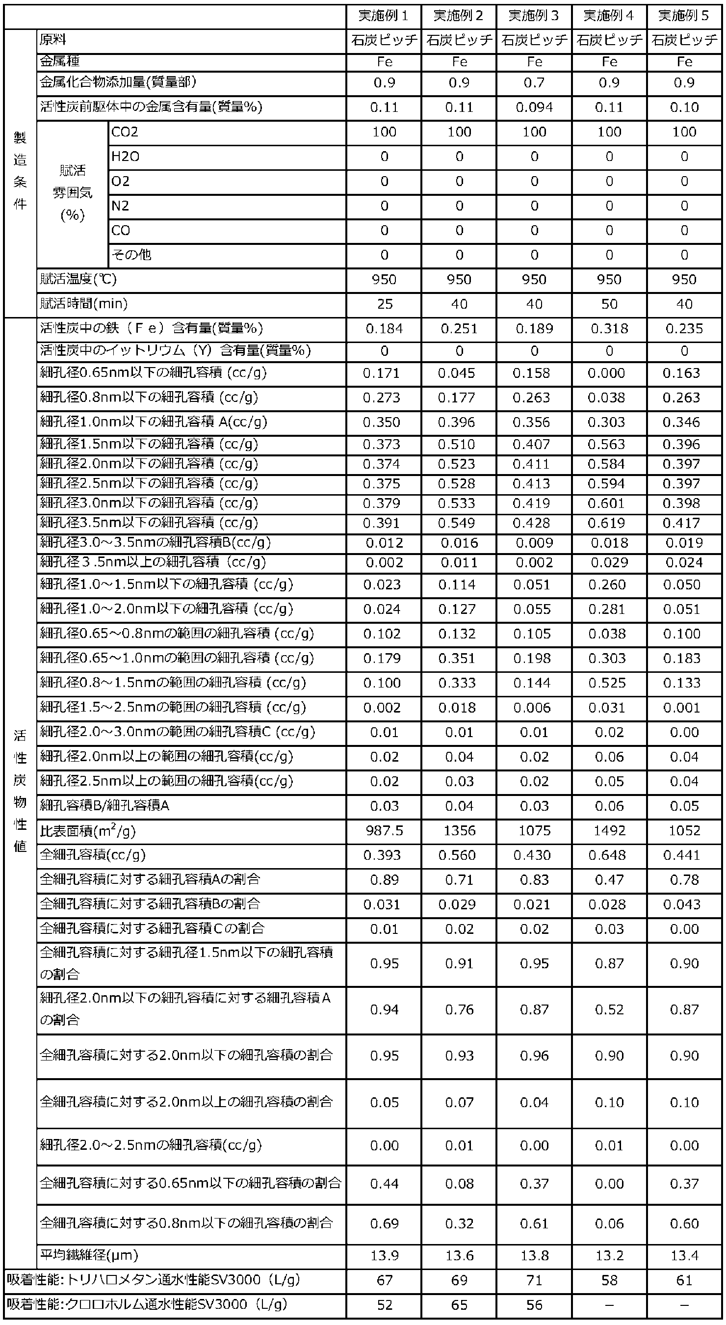
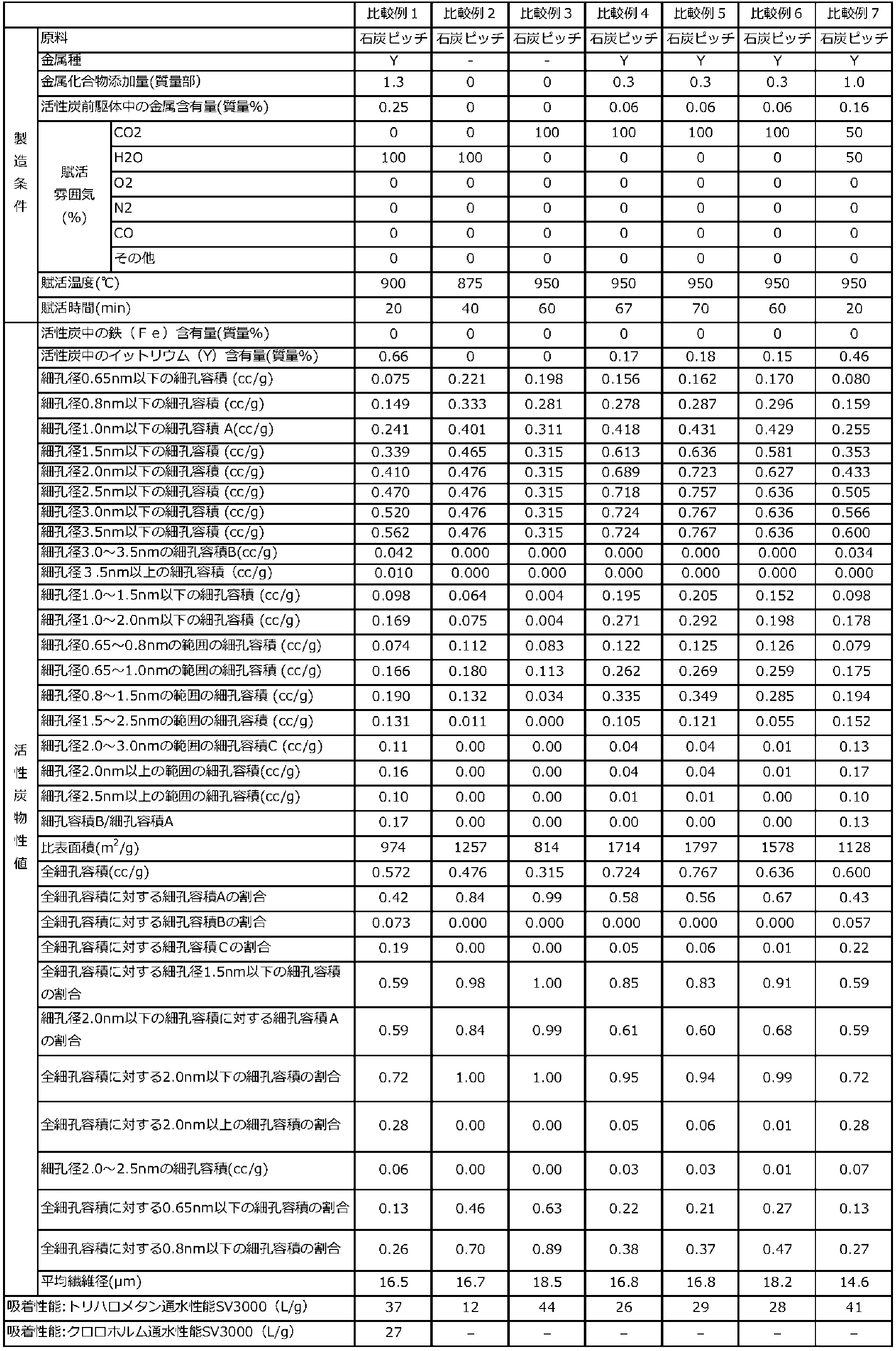
実施例1~5の活性炭は、QSDFT法によって算出される細孔容積のうち、1.0nm以下の範囲の細孔径の細孔容積Aが0.3cc/g以上であり、かつ、QSDFT法によって算出される細孔容積のうち、3.0nm以上3.5nm以下の範囲の細孔径の細孔容積Bが0.009cc/g以上であることから、大きな空塔速度(SV)での通水処理においても、高い総トリハロメタンろ過能力を有する活性炭を得ることができるものであった。
一方、比較例1及び7の活性炭は、QSDFT法によって算出される細孔容積のうち、1.0nm以下の範囲の細孔径の細孔容積Aが0.3cc/g未満であったことから、上記総トリハロメタンろ過能力が劣るものであった。
比較例2~6の活性炭は、QSDFT法によって算出される細孔容積のうち、3.0nm以上3.5nm以下の範囲の細孔径の細孔容積Bが0.009cc/g未満であったことから、上記総トリハロメタンろ過能力が劣るものであった。
Claims (7)
- QSDFT法によって算出される細孔容積のうち、1.0nm以下の範囲の細孔径の細孔容積Aが0.3cc/g以上であり、
かつ、QSDFT法によって算出される細孔容積のうち、3.0nm以上3.5nm以下の範囲の細孔径の細孔容積Bが0.009cc/g以上である、活性炭。 - QSDFT法によって算出される細孔容積のうち、2.0nm以上3.0nm以下の範囲の細孔径の細孔容積Cが0.05cc/g以下である、請求項1に記載の活性炭。
- QSDFT法によって算出される活性炭の全細孔容積(cc/g)に対する、QSDFT法によって算出される細孔容積のうち、1.5nm以下の範囲の細孔径の細孔容積(cc/g)の割合が0.85以上である、請求項1又は2に記載の活性炭。
- 比表面積が500~1800m2/gである、請求項1~3のいずれか1項に記載の活性炭。
- 総トリハロメタンろ過能力が45L/g以上である、請求項1~4のいずれか1項に記載の活性炭。
- 前記活性炭が繊維状活性炭である、請求項1~5のいずれか1項に記載の活性炭。
- 鉄を0.1~1.5質量%含む活性炭前駆体を、CO2濃度が90容積%以上の雰囲気下、温度900~1000℃で賦活する工程を含む、請求項1~6のいずれか1項に記載の活性炭の製造方法。
Priority Applications (3)
| Application Number | Priority Date | Filing Date | Title |
|---|---|---|---|
| JP2019563308A JP6683968B1 (ja) | 2018-06-19 | 2019-06-18 | 活性炭 |
| EP19822785.2A EP3812348A4 (en) | 2018-06-19 | 2019-06-18 | CHARCOAL |
| US17/253,154 US11873235B2 (en) | 2018-06-19 | 2019-06-18 | Activated carbon |
Applications Claiming Priority (2)
| Application Number | Priority Date | Filing Date | Title |
|---|---|---|---|
| JP2018-116188 | 2018-06-19 | ||
| JP2018116188 | 2018-06-19 |
Publications (1)
| Publication Number | Publication Date |
|---|---|
| WO2019244903A1 true WO2019244903A1 (ja) | 2019-12-26 |
Family
ID=68984071
Family Applications (1)
| Application Number | Title | Priority Date | Filing Date |
|---|---|---|---|
| PCT/JP2019/024169 Ceased WO2019244903A1 (ja) | 2018-06-19 | 2019-06-18 | 活性炭 |
Country Status (4)
| Country | Link |
|---|---|
| US (1) | US11873235B2 (ja) |
| EP (1) | EP3812348A4 (ja) |
| JP (2) | JP6683968B1 (ja) |
| WO (1) | WO2019244903A1 (ja) |
Cited By (2)
| Publication number | Priority date | Publication date | Assignee | Title |
|---|---|---|---|---|
| WO2023032633A1 (ja) | 2021-09-06 | 2023-03-09 | 株式会社アドール | 活性炭 |
| US11795066B2 (en) | 2020-06-30 | 2023-10-24 | Kuraray Co., Ltd. | Carbonaceous material and method for producing same, water purification filter, and water purifier |
Families Citing this family (4)
| Publication number | Priority date | Publication date | Assignee | Title |
|---|---|---|---|---|
| JP7300124B2 (ja) * | 2019-01-31 | 2023-06-29 | 株式会社タカギ | トリハロメタン除去用活性炭およびその製造方法 |
| JP7300656B2 (ja) * | 2021-05-31 | 2023-06-30 | 戸田工業株式会社 | 土壌・地下水浄化処理用浄化剤及びその製造方法、並びに土壌・地下水の浄化処理方法 |
| EP4656600A1 (en) * | 2023-01-25 | 2025-12-03 | Unitika Ltd. | Filter |
| WO2025141536A1 (en) * | 2023-12-28 | 2025-07-03 | Loam Bio Pty Ltd | Compositions, systems, and methods of reducing methane emissions |
Citations (9)
| Publication number | Priority date | Publication date | Assignee | Title |
|---|---|---|---|---|
| JPH07155589A (ja) * | 1993-12-09 | 1995-06-20 | Mitsubishi Gas Chem Co Inc | 高比表面積炭素材料の製造方法 |
| JPH10328563A (ja) * | 1997-05-30 | 1998-12-15 | Adall:Kk | 有害ガス除去用素材およびその製造方法 |
| JP2004182511A (ja) | 2002-12-02 | 2004-07-02 | Ad'all Co Ltd | 活性炭及びその製造方法 |
| JP2005001968A (ja) * | 2003-06-13 | 2005-01-06 | Nippon Steel Chem Co Ltd | 多孔質炭素の製造方法 |
| JP2006247527A (ja) | 2005-03-10 | 2006-09-21 | Kansai Coke & Chem Co Ltd | 吸着剤 |
| JP2017178635A (ja) * | 2016-03-28 | 2017-10-05 | 株式会社アドール | 炭素材料の製造方法 |
| JP2017179616A (ja) * | 2016-03-28 | 2017-10-05 | 株式会社アドール | 金属単体及び金属化合物の少なくとも一方を含有する活性炭の製造方法 |
| WO2017213057A1 (ja) * | 2016-06-06 | 2017-12-14 | 住友電気工業株式会社 | 電気二重層キャパシタ電極用の多孔質炭素材料、その製造方法および電気二重層キャパシタ電極 |
| JP2018039685A (ja) * | 2016-09-05 | 2018-03-15 | 旭化成株式会社 | 多孔質炭素材料及びその製造方法、複合体及びその製造方法、並びにリチウム硫黄電池用の正極材料 |
Family Cites Families (5)
| Publication number | Priority date | Publication date | Assignee | Title |
|---|---|---|---|---|
| JP3390649B2 (ja) * | 1997-06-02 | 2003-03-24 | カネボウ株式会社 | 球状炭素材及びその製造方法 |
| JPH11240707A (ja) * | 1998-02-27 | 1999-09-07 | Adooru:Kk | 活性炭 |
| JPWO2003026792A1 (ja) * | 2001-09-26 | 2005-01-06 | 株式会社アドール | 活性炭素繊維及びその製造方法 |
| WO2015152391A1 (ja) * | 2014-04-03 | 2015-10-08 | 関西熱化学株式会社 | 浄水器用活性炭 |
| DE102016101215A1 (de) * | 2015-12-10 | 2017-06-14 | BLüCHER GMBH | Verfahren zur Herstellung von Aktivkohle und auf diese Weise hergestellte Aktivkohle sowie deren Verwendung |
-
2019
- 2019-06-18 EP EP19822785.2A patent/EP3812348A4/en active Pending
- 2019-06-18 WO PCT/JP2019/024169 patent/WO2019244903A1/ja not_active Ceased
- 2019-06-18 JP JP2019563308A patent/JP6683968B1/ja active Active
- 2019-06-18 US US17/253,154 patent/US11873235B2/en active Active
-
2020
- 2020-03-11 JP JP2020042334A patent/JP7491506B2/ja active Active
Patent Citations (9)
| Publication number | Priority date | Publication date | Assignee | Title |
|---|---|---|---|---|
| JPH07155589A (ja) * | 1993-12-09 | 1995-06-20 | Mitsubishi Gas Chem Co Inc | 高比表面積炭素材料の製造方法 |
| JPH10328563A (ja) * | 1997-05-30 | 1998-12-15 | Adall:Kk | 有害ガス除去用素材およびその製造方法 |
| JP2004182511A (ja) | 2002-12-02 | 2004-07-02 | Ad'all Co Ltd | 活性炭及びその製造方法 |
| JP2005001968A (ja) * | 2003-06-13 | 2005-01-06 | Nippon Steel Chem Co Ltd | 多孔質炭素の製造方法 |
| JP2006247527A (ja) | 2005-03-10 | 2006-09-21 | Kansai Coke & Chem Co Ltd | 吸着剤 |
| JP2017178635A (ja) * | 2016-03-28 | 2017-10-05 | 株式会社アドール | 炭素材料の製造方法 |
| JP2017179616A (ja) * | 2016-03-28 | 2017-10-05 | 株式会社アドール | 金属単体及び金属化合物の少なくとも一方を含有する活性炭の製造方法 |
| WO2017213057A1 (ja) * | 2016-06-06 | 2017-12-14 | 住友電気工業株式会社 | 電気二重層キャパシタ電極用の多孔質炭素材料、その製造方法および電気二重層キャパシタ電極 |
| JP2018039685A (ja) * | 2016-09-05 | 2018-03-15 | 旭化成株式会社 | 多孔質炭素材料及びその製造方法、複合体及びその製造方法、並びにリチウム硫黄電池用の正極材料 |
Non-Patent Citations (1)
| Title |
|---|
| See also references of EP3812348A4 |
Cited By (2)
| Publication number | Priority date | Publication date | Assignee | Title |
|---|---|---|---|---|
| US11795066B2 (en) | 2020-06-30 | 2023-10-24 | Kuraray Co., Ltd. | Carbonaceous material and method for producing same, water purification filter, and water purifier |
| WO2023032633A1 (ja) | 2021-09-06 | 2023-03-09 | 株式会社アドール | 活性炭 |
Also Published As
| Publication number | Publication date |
|---|---|
| EP3812348A1 (en) | 2021-04-28 |
| EP3812348A4 (en) | 2022-02-09 |
| US20210261441A1 (en) | 2021-08-26 |
| JPWO2019244903A1 (ja) | 2020-06-25 |
| JP2020110801A (ja) | 2020-07-27 |
| JP7491506B2 (ja) | 2024-05-28 |
| JP6683968B1 (ja) | 2020-04-22 |
| US11873235B2 (en) | 2024-01-16 |
Similar Documents
| Publication | Publication Date | Title |
|---|---|---|
| JP6683968B1 (ja) | 活性炭 | |
| JP6379325B1 (ja) | 活性炭及びその製造方法 | |
| JP2022132348A (ja) | 活性炭及びその製造方法 | |
| JP6379324B1 (ja) | 活性炭及びその製造方法 | |
| JP7441296B2 (ja) | 活性炭の製造方法 | |
| JP7597901B1 (ja) | 炭素質材料及びその製造方法、吸着フィルター、浄水器カートリッジ、浄水器、並びに水浄化設備 | |
| JP2004182511A (ja) | 活性炭及びその製造方法 | |
| JP6719709B2 (ja) | 活性炭 | |
| JP7428347B2 (ja) | 活性炭 | |
| US20250121353A1 (en) | Activated carbon | |
| CN111247097B (zh) | 活性炭及该活性炭的制备方法 | |
| JP7300124B2 (ja) | トリハロメタン除去用活性炭およびその製造方法 | |
| JPWO2003026792A1 (ja) | 活性炭素繊維及びその製造方法 | |
| KR20260059600A (ko) | 탄소질 재료 및 그 제조 방법, 흡착 필터, 정수기 카트리지, 정수기, 그리고 물 정화 설비 | |
| JP2006315903A (ja) | 繊維状活性炭 |
Legal Events
| Date | Code | Title | Description |
|---|---|---|---|
| ENP | Entry into the national phase |
Ref document number: 2019563308 Country of ref document: JP Kind code of ref document: A |
|
| 121 | Ep: the epo has been informed by wipo that ep was designated in this application |
Ref document number: 19822785 Country of ref document: EP Kind code of ref document: A1 |
|
| NENP | Non-entry into the national phase |
Ref country code: DE |
|
| ENP | Entry into the national phase |
Ref document number: 2019822785 Country of ref document: EP Effective date: 20210119 |