WO2020003590A1 - 冷凍サイクル装置およびそれを備えた液体加熱装置 - Google Patents
冷凍サイクル装置およびそれを備えた液体加熱装置 Download PDFInfo
- Publication number
- WO2020003590A1 WO2020003590A1 PCT/JP2019/006195 JP2019006195W WO2020003590A1 WO 2020003590 A1 WO2020003590 A1 WO 2020003590A1 JP 2019006195 W JP2019006195 W JP 2019006195W WO 2020003590 A1 WO2020003590 A1 WO 2020003590A1
- Authority
- WO
- WIPO (PCT)
- Prior art keywords
- heat exchanger
- refrigerant
- side heat
- expansion device
- operation mode
- Prior art date
- Legal status (The legal status is an assumption and is not a legal conclusion. Google has not performed a legal analysis and makes no representation as to the accuracy of the status listed.)
- Ceased
Links
Images


Classifications
-
- F—MECHANICAL ENGINEERING; LIGHTING; HEATING; WEAPONS; BLASTING
- F25—REFRIGERATION OR COOLING; COMBINED HEATING AND REFRIGERATION SYSTEMS; HEAT PUMP SYSTEMS; MANUFACTURE OR STORAGE OF ICE; LIQUEFACTION SOLIDIFICATION OF GASES
- F25B—REFRIGERATION MACHINES, PLANTS OR SYSTEMS; COMBINED HEATING AND REFRIGERATION SYSTEMS; HEAT PUMP SYSTEMS
- F25B13/00—Compression machines, plants or systems, with reversible cycle
-
- F—MECHANICAL ENGINEERING; LIGHTING; HEATING; WEAPONS; BLASTING
- F25—REFRIGERATION OR COOLING; COMBINED HEATING AND REFRIGERATION SYSTEMS; HEAT PUMP SYSTEMS; MANUFACTURE OR STORAGE OF ICE; LIQUEFACTION SOLIDIFICATION OF GASES
- F25B—REFRIGERATION MACHINES, PLANTS OR SYSTEMS; COMBINED HEATING AND REFRIGERATION SYSTEMS; HEAT PUMP SYSTEMS
- F25B47/00—Arrangements for preventing or removing deposits or corrosion, not provided for in another subclass
- F25B47/02—Defrosting cycles
- F25B47/022—Defrosting cycles hot gas defrosting
-
- F—MECHANICAL ENGINEERING; LIGHTING; HEATING; WEAPONS; BLASTING
- F25—REFRIGERATION OR COOLING; COMBINED HEATING AND REFRIGERATION SYSTEMS; HEAT PUMP SYSTEMS; MANUFACTURE OR STORAGE OF ICE; LIQUEFACTION SOLIDIFICATION OF GASES
- F25B—REFRIGERATION MACHINES, PLANTS OR SYSTEMS; COMBINED HEATING AND REFRIGERATION SYSTEMS; HEAT PUMP SYSTEMS
- F25B47/00—Arrangements for preventing or removing deposits or corrosion, not provided for in another subclass
- F25B47/02—Defrosting cycles
- F25B47/022—Defrosting cycles hot gas defrosting
- F25B47/025—Defrosting cycles hot gas defrosting by reversing the cycle
-
- F—MECHANICAL ENGINEERING; LIGHTING; HEATING; WEAPONS; BLASTING
- F25—REFRIGERATION OR COOLING; COMBINED HEATING AND REFRIGERATION SYSTEMS; HEAT PUMP SYSTEMS; MANUFACTURE OR STORAGE OF ICE; LIQUEFACTION SOLIDIFICATION OF GASES
- F25B—REFRIGERATION MACHINES, PLANTS OR SYSTEMS; COMBINED HEATING AND REFRIGERATION SYSTEMS; HEAT PUMP SYSTEMS
- F25B49/00—Arrangement or mounting of control or safety devices
- F25B49/02—Arrangement or mounting of control or safety devices for compression type machines, plants or systems
-
- F—MECHANICAL ENGINEERING; LIGHTING; HEATING; WEAPONS; BLASTING
- F25—REFRIGERATION OR COOLING; COMBINED HEATING AND REFRIGERATION SYSTEMS; HEAT PUMP SYSTEMS; MANUFACTURE OR STORAGE OF ICE; LIQUEFACTION SOLIDIFICATION OF GASES
- F25B—REFRIGERATION MACHINES, PLANTS OR SYSTEMS; COMBINED HEATING AND REFRIGERATION SYSTEMS; HEAT PUMP SYSTEMS
- F25B1/00—Compression machines, plants or systems with non-reversible cycle
- F25B1/10—Compression machines, plants or systems with non-reversible cycle with multi-stage compression
-
- F—MECHANICAL ENGINEERING; LIGHTING; HEATING; WEAPONS; BLASTING
- F25—REFRIGERATION OR COOLING; COMBINED HEATING AND REFRIGERATION SYSTEMS; HEAT PUMP SYSTEMS; MANUFACTURE OR STORAGE OF ICE; LIQUEFACTION SOLIDIFICATION OF GASES
- F25B—REFRIGERATION MACHINES, PLANTS OR SYSTEMS; COMBINED HEATING AND REFRIGERATION SYSTEMS; HEAT PUMP SYSTEMS
- F25B2313/00—Compression machines, plants or systems with reversible cycle not otherwise provided for
- F25B2313/003—Indoor unit with water as a heat sink or heat source
-
- F—MECHANICAL ENGINEERING; LIGHTING; HEATING; WEAPONS; BLASTING
- F25—REFRIGERATION OR COOLING; COMBINED HEATING AND REFRIGERATION SYSTEMS; HEAT PUMP SYSTEMS; MANUFACTURE OR STORAGE OF ICE; LIQUEFACTION SOLIDIFICATION OF GASES
- F25B—REFRIGERATION MACHINES, PLANTS OR SYSTEMS; COMBINED HEATING AND REFRIGERATION SYSTEMS; HEAT PUMP SYSTEMS
- F25B2339/00—Details of evaporators; Details of condensers
- F25B2339/04—Details of condensers
- F25B2339/047—Water-cooled condensers
-
- F—MECHANICAL ENGINEERING; LIGHTING; HEATING; WEAPONS; BLASTING
- F25—REFRIGERATION OR COOLING; COMBINED HEATING AND REFRIGERATION SYSTEMS; HEAT PUMP SYSTEMS; MANUFACTURE OR STORAGE OF ICE; LIQUEFACTION SOLIDIFICATION OF GASES
- F25B—REFRIGERATION MACHINES, PLANTS OR SYSTEMS; COMBINED HEATING AND REFRIGERATION SYSTEMS; HEAT PUMP SYSTEMS
- F25B2600/00—Control issues
- F25B2600/13—Pump speed control
-
- F—MECHANICAL ENGINEERING; LIGHTING; HEATING; WEAPONS; BLASTING
- F25—REFRIGERATION OR COOLING; COMBINED HEATING AND REFRIGERATION SYSTEMS; HEAT PUMP SYSTEMS; MANUFACTURE OR STORAGE OF ICE; LIQUEFACTION SOLIDIFICATION OF GASES
- F25B—REFRIGERATION MACHINES, PLANTS OR SYSTEMS; COMBINED HEATING AND REFRIGERATION SYSTEMS; HEAT PUMP SYSTEMS
- F25B2600/00—Control issues
- F25B2600/25—Control of valves
- F25B2600/2509—Economiser valves
-
- F—MECHANICAL ENGINEERING; LIGHTING; HEATING; WEAPONS; BLASTING
- F25—REFRIGERATION OR COOLING; COMBINED HEATING AND REFRIGERATION SYSTEMS; HEAT PUMP SYSTEMS; MANUFACTURE OR STORAGE OF ICE; LIQUEFACTION SOLIDIFICATION OF GASES
- F25B—REFRIGERATION MACHINES, PLANTS OR SYSTEMS; COMBINED HEATING AND REFRIGERATION SYSTEMS; HEAT PUMP SYSTEMS
- F25B2600/00—Control issues
- F25B2600/25—Control of valves
- F25B2600/2513—Expansion valves
-
- F—MECHANICAL ENGINEERING; LIGHTING; HEATING; WEAPONS; BLASTING
- F25—REFRIGERATION OR COOLING; COMBINED HEATING AND REFRIGERATION SYSTEMS; HEAT PUMP SYSTEMS; MANUFACTURE OR STORAGE OF ICE; LIQUEFACTION SOLIDIFICATION OF GASES
- F25B—REFRIGERATION MACHINES, PLANTS OR SYSTEMS; COMBINED HEATING AND REFRIGERATION SYSTEMS; HEAT PUMP SYSTEMS
- F25B2700/00—Sensing or detecting of parameters; Sensors therefor
- F25B2700/19—Pressures
- F25B2700/193—Pressures of the compressor
- F25B2700/1933—Suction pressures
-
- F—MECHANICAL ENGINEERING; LIGHTING; HEATING; WEAPONS; BLASTING
- F25—REFRIGERATION OR COOLING; COMBINED HEATING AND REFRIGERATION SYSTEMS; HEAT PUMP SYSTEMS; MANUFACTURE OR STORAGE OF ICE; LIQUEFACTION SOLIDIFICATION OF GASES
- F25B—REFRIGERATION MACHINES, PLANTS OR SYSTEMS; COMBINED HEATING AND REFRIGERATION SYSTEMS; HEAT PUMP SYSTEMS
- F25B2700/00—Sensing or detecting of parameters; Sensors therefor
- F25B2700/21—Temperatures
- F25B2700/2117—Temperatures of an evaporator
-
- Y—GENERAL TAGGING OF NEW TECHNOLOGICAL DEVELOPMENTS; GENERAL TAGGING OF CROSS-SECTIONAL TECHNOLOGIES SPANNING OVER SEVERAL SECTIONS OF THE IPC; TECHNICAL SUBJECTS COVERED BY FORMER USPC CROSS-REFERENCE ART COLLECTIONS [XRACs] AND DIGESTS
- Y02—TECHNOLOGIES OR APPLICATIONS FOR MITIGATION OR ADAPTATION AGAINST CLIMATE CHANGE
- Y02B—CLIMATE CHANGE MITIGATION TECHNOLOGIES RELATED TO BUILDINGS, e.g. HOUSING, HOUSE APPLIANCES OR RELATED END-USER APPLICATIONS
- Y02B30/00—Energy efficient heating, ventilation or air conditioning [HVAC]
- Y02B30/70—Efficient control or regulation technologies, e.g. for control of refrigerant flow, motor or heating
Definitions
- the present invention relates to a refrigeration cycle device and a liquid heating device including the same.
- a refrigeration cycle device of this type a two-stage compressor is provided, a part of the refrigerant is expanded from the downstream side of the use side heat exchanger, and the intermediate refrigerant is bypassed during the compression of the two-stage compressor.
- a refrigeration cycle device is disclosed (for example, see Patent Document 1).
- FIG. 3 shows a conventional refrigeration cycle device described in Patent Document 1.
- the refrigeration cycle apparatus 100 includes a refrigerant circuit 110 for circulating a refrigerant, and a rear-stage injection pipe 120.
- a compression mechanism 111 having a plurality of compression rotation elements connected in series
- a heat source side heat exchanger 112 expansion mechanisms 113a and 113b
- a use side heat exchanger 114 are connected in a ring by piping.
- a switching mechanism 115 for switching between the heating operation and the cooling operation is provided.
- the refrigeration cycle apparatus 100 includes an intermediate refrigerant pipe 116 for allowing the refrigerant discharged from the upstream compression rotation element to be sucked into the downstream compression rotation element.
- An intercooler 117 is provided which functions as a cooler for the refrigerant discharged from the element and drawn into the compression rotary element on the subsequent stage.
- the intermediate refrigerant pipe 116 is provided with an intermediate cooler bypass pipe 130 that bypasses the intermediate cooler 117.
- the second-stage injection pipe 120 branches from the refrigerant circuit 110 between the heat-source-side heat exchanger 112 and the use-side heat exchanger 114, and is communicated so that the branched refrigerant returns to the second-stage compression rotating element of the compression mechanism 111. ing. Further, the injection pipe 120 is provided with a second-stage injection valve 121 capable of controlling the opening degree.
- the refrigeration cycle apparatus 100 when performing the reverse cycle defrosting operation of defrosting the heat source side heat exchanger 112 by switching the switching mechanism 115 to the cooling operation state, the refrigeration cycle apparatus 100 includes the heat source side heat exchanger 112 and the intercooler. After the refrigerant is passed through the intercooler 117 and the post-stage injection pipe 120 and the completion of the defrosting of the intercooler 117 is detected, the refrigerant is prevented from flowing into the intercooler 117 by using the intercooler bypass pipe 130. At the same time, control is performed such that the opening degree of the rear injection valve 121 is increased.
- the low-pressure / low-temperature refrigerant circulates in the use-side heat exchanger during the defrosting operation of the heat source-side heat exchanger. Therefore, there is a problem that the use side heat exchanger is cooled, and the increase in the heating capacity of the use side heat exchanger during the heating operation after the defrosting operation of the heat source side heat exchanger is completed is delayed.
- the present invention solves the above-mentioned conventional problems, even when performing the heating operation in the use-side heat exchanger after the execution of the defrosting operation of the heat source-side heat exchanger, the heating operation in the use-side heat exchanger. It is an object of the present invention to provide a refrigeration cycle device capable of suppressing a decrease in the heating capacity of a refrigeration cycle and a liquid heating device including the refrigeration cycle device.
- a refrigeration cycle apparatus includes a compression mechanism including a compression rotation element, and a usage-side heat exchanger that heats a usage-side heat medium with a refrigerant discharged from the compression rotation element.
- a main refrigerant circuit formed by sequentially connecting an intermediate heat exchanger, a first expansion device, and a heat source side heat exchanger with piping, and the piping from the use side heat exchanger to the first expansion device.
- the refrigerant that has been branched from the refrigerant is decompressed by the second expansion device, and then heat-exchanged with the refrigerant flowing through the main refrigerant circuit in the intermediate heat exchanger.
- a heating operation mode that includes a bypass refrigerant circuit to be joined, and a control device, wherein the refrigerant discharged from the compression rotary element heats the use-side heat medium in the use-side heat exchanger;
- a defrosting operation mode for performing defrosting of the heat source side heat exchanger by the refrigerant discharged from the element; and the control device includes an opening degree of the first expansion device and an opening degree of the second expansion device.
- the refrigerant flow rate is adjusted so as to make the flow rate of the refrigerant flowing through the first expansion device larger than the flow rate of the refrigerant flowing through the second expansion device during the execution of the defrosting operation mode.
- the first expansion device is operated during the defrosting operation mode. Since the flow rate of the refrigerant flowing through the second expansion device is higher than the flow rate of the refrigerant flowing through the second expansion device, the refrigerant passing through the use-side heat exchanger does not become low-temperature and low-pressure, so that a decrease in the temperature of the use-side heat exchanger can be suppressed. It is possible to provide a refrigeration cycle apparatus capable of suppressing a decrease in the heating capacity of the use side heat exchanger during the heating operation even when the use side heat exchanger performs the heating operation after the execution of the defrost operation of the side heat exchanger.
- the amount of refrigerant passing through the usage-side heat exchanger also increases. Since the heat of the use-side heat medium staying in the side heat exchanger can also be used for defrosting the heat source side heat exchanger, the defrosting ability in the defrost operation mode can be improved.
- ADVANTAGE OF THE INVENTION According to this invention, even at the time of performing the heating operation in the use side heat exchanger after the completion of the defrosting operation of the heat source side heat exchanger, it is possible to suppress a decrease in the heating capacity of the use side heat exchanger during the heating operation.
- a refrigeration cycle device and a liquid heating device including the same can be provided.
- a first invention provides a compression mechanism including a compression rotary element, a use side heat exchanger that heats a use side heat medium with a refrigerant discharged from the compression rotary element, an intermediate heat exchanger, a first expansion device, and a heat source.
- the main refrigerant circuit formed by sequentially connecting the side heat exchangers by pipes and the pipe from the use side heat exchanger to the first expansion device are branched from the pipe, and the branched refrigerant is subjected to the second expansion.
- the intermediate heat exchanger exchanges heat with the refrigerant flowing through the main refrigerant circuit, and includes a bypass refrigerant circuit that is joined to the refrigerant in the middle of compression of the compression rotary element, and a control device, A heating operation mode in which the use-side heat medium is heated in the use-side heat exchanger by the refrigerant discharged from the compression rotation element; and a removal of the heat-source-side heat exchanger by the refrigerant discharged from the compression rotation element.
- Do frost A defrost operation mode, wherein the control device adjusts an opening degree of the first expansion device and an opening degree of the second expansion device, and performs the first defrost operation mode during execution of the defrost operation mode.
- a refrigeration cycle apparatus characterized in that the flow rate of the refrigerant flowing through the expansion device is made larger than the flow amount of the refrigerant flowing through the second expansion device.
- the first expansion device is operated during the defrosting operation mode. Since the flow rate of the refrigerant flowing through the second expansion device is higher than the flow rate of the refrigerant flowing through the second expansion device, the refrigerant passing through the use-side heat exchanger does not have a low temperature and a low pressure, so that a decrease in the temperature of the use-side heat exchanger can be suppressed.
- the capacity can be quickly increased, and even when the heating operation in the use side heat exchanger is performed after the completion of the defrosting operation of the heat source side heat exchanger, the heating capacity of the use side heat exchanger during the heating operation is reduced.
- a refrigeration cycle device that can be suppressed can be provided.
- the amount of refrigerant passing through the usage-side heat exchanger also increases. Since the heat of the use-side heat medium staying in the side heat exchanger can also be used for defrosting the heat source side heat exchanger, the defrosting ability in the defrost operation mode can be improved.
- control device operates the first expansion device faster than the second expansion device, and the flow rate of the refrigerant flowing through the first expansion device is The opening degree is set to be larger than the flow rate of the refrigerant flowing through the second expansion device.
- the first expansion device to operate earlier than the second expansion device at an opening degree at which the flow rate of the refrigerant flowing through the first expansion device is greater than the flow rate of the refrigerant flowing through the second expansion device, so that the main refrigerant is quickly released.
- the difference between the high and low pressures of the refrigerant in the circuit can be reduced, and the refrigerant flow rate of the refrigerant discharged from the compression rotary element that can be supplied to the heat source side heat exchanger in the defrosting operation mode can be rapidly increased.
- the refrigerant discharged from the compression rotary element is the use-side heat exchanger and the first expansion device. , And flows in the order of the heat source side heat exchanger.
- the high-temperature discharge refrigerant flows through the use-side heat exchanger, so that the temperature of the use-side heat exchanger is prevented from lowering, and the heating performed after the execution of the defrost operation mode is completed.
- the temperature rise of the use side heat exchanger can be promoted, and the heating capacity can be quickly increased even in the heating operation mode after the execution of the defrosting operation mode under the high humidity outside air temperature condition with a large amount of frost.
- 4A fourth invention is characterized in that, in any one of the first to third inventions, carbon dioxide is used as the refrigerant.
- the temperature of the use-side heat medium can be increased.
- a fifth aspect of the present invention is a liquid heating apparatus, comprising: the refrigeration cycle device according to any one of the first to fourth aspects; and a use-side heat medium circuit that circulates the use-side heat medium by a transport device. It is.
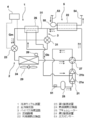
- FIG. 1 shows a configuration diagram of a liquid heating device according to a first embodiment of the present invention.
- the liquid heating device includes a refrigeration cycle device 1, a use-side heat medium circuit 5, and a control device 4 for controlling the operation of the liquid heating device.
- the refrigeration cycle device 1 includes a main refrigerant circuit 2 and a bypass refrigerant circuit 3.
- the main refrigerant circuit 2 includes a compression mechanism 21, a use-side heat exchanger 22 as a radiator, an intermediate heat exchanger 26 as a cooling heat exchanger, a first expansion device 23, and a heat source-side heat exchanger as an evaporator. 24 are formed by being sequentially connected by a pipe 16, and use carbon dioxide (CO2) as a refrigerant.
- CO2 carbon dioxide
- carbon dioxide is most preferably used as the refrigerant, for example, a non-azeotropic mixed refrigerant such as R407C, a pseudo-azeotropic mixed refrigerant such as R410A, or a single refrigerant such as R32 can also be used.
- a non-azeotropic mixed refrigerant such as R407C
- a pseudo-azeotropic mixed refrigerant such as R410A
- a single refrigerant such as R32
- the compression mechanism 21 for compressing the refrigerant includes a low-stage compression rotation element 21a and a high-stage compression rotation element 21b.
- the use-side heat exchanger 22 heats the use-side heat medium with the refrigerant discharged from the high-stage compression rotation element 21b.
- the volume ratio between the low-stage compression rotation element 21a and the high-stage compression rotation element 21b constituting the compression mechanism 21 is constant, and the drive shaft (not shown) is shared and arranged in one container. It is composed of one compressor.
- the description will be made using the compression mechanism 21 in which the compression rotation element includes the low-stage compression rotation element 21a and the high-stage compression rotation element 21b.
- the position where the refrigerant from the bypass refrigerant circuit 3 joins is set in the middle of compression of the compression rotary element, and the compression rotation to the position where the refrigerant from the bypass refrigerant circuit 3 joins is performed.
- the element can be used as the low-stage compression rotation element 21a, and the compression rotation element after the position where the refrigerant from the bypass refrigerant circuit 3 joins can be used as the high-stage compression rotation element 21b.
- the structure of the compression mechanism 21 in which the low-stage compression rotation element 21a and the high-stage compression rotation element 21b are each composed of two independent compressors may be used.
- the bypass refrigerant circuit 3 is branched from the pipe 16 between the use side heat exchanger 22 and the first expansion device 23, and is connected between the low-stage compression rotation element 21a and the high-stage compression rotation element 21b. I have.
- a second expansion device 31 is provided in the bypass refrigerant circuit 3.
- a part of the high-pressure refrigerant after passing through the use-side heat exchanger 22 or a part of the high-pressure refrigerant after passing through the intermediate heat exchanger 26 is decompressed by the second expansion device 31 and becomes an intermediate-pressure refrigerant.
- the intermediate heat exchanger 26 heat exchange is performed with the high-pressure refrigerant flowing through the main refrigerant circuit 2, and the refrigerant is merged with the refrigerant between the low-stage compression rotation element 21a and the high-stage compression rotation element 21b.
- an accumulator 25 for performing gas-liquid separation is provided between the outlet side of the heat source side heat exchanger 24 and the suction side of the compression mechanism 21, an accumulator 25 for performing gas-liquid separation is provided.
- the main refrigerant circuit 2 whether the high-pressure refrigerant discharged from the compression mechanism 21 flows to the use-side heat exchanger 22 or the heat-source-side heat exchanger 24 in the main refrigerant circuit 2.
- a four-way valve 27 for switching the path is provided.
- the use-side heat exchanger 22 is connected to a heat medium return pipe 53 and a heat medium going pipe 54.
- the heat medium return pipe 53 is provided with a transfer device 55 that is a transfer pump.
- the transfer device 55 operates, the use-side heat medium is supplied to the use-side heat exchanger 22 through the heat medium return pipe 53, and the use-side heat medium heated by the use-side heat exchanger 22 flows out of the heat medium.
- a heater not shown
- a hot water storage tank not shown
- the pipe 16 connecting the downstream side of the first expansion device 23 and the suction side of the compression mechanism 21 is a low pressure side circuit of the main refrigerant circuit 2, and the pipe 16 of the low pressure side circuit has a low pressure side detection unit as A pressure sensor 51 for detecting the evaporation pressure of the low pressure side circuit is provided.
- An evaporating temperature thermistor (not shown) is provided in the pipe 16 of the low pressure side circuit of the main refrigerant circuit 2 and detects the evaporating temperature of the refrigerant in the gas-liquid two-layer state flowing through the low pressure side circuit as the low pressure side detection unit. May be used.
- a temperature thermistor 28 is provided around the heat source side heat exchanger 24, and when the fan 29 is driven, the temperature thermistor 28 detects the temperature of the air that supplies heat to the heat source side heat exchanger 24. are doing.
- the refrigeration cycle apparatus 1 has a heating operation mode and a defrosting operation mode.
- the heating operation mode the use-side heat medium circulated in the use-side heat exchanger 22 is heated by the refrigerant discharged from the high-stage compression rotation element 21b of the compression mechanism 21.
- the transfer device 55 is operated to circulate the use side heat medium to the use side heat exchanger 22.
- the defrosting operation mode the refrigerant discharged from the high-stage compression rotating element 21b of the compression mechanism 21 performs defrosting on the heat source side heat exchanger 24.
- the control device 4 when the detected pressure detected by the pressure sensor 51 or the detected temperature detected by the evaporating temperature thermistor becomes equal to or less than a predetermined value, respectively, or the heat source side heat exchanger detected by the temperature thermistor 28 If the temperature of the air that supplies heat to the heat source 24 is equal to or lower than a predetermined value and the execution time of the heating operation mode continues for a predetermined time or more in that state, it is determined that the heat source side heat exchanger 24 is frosted. To execute the defrost operation mode. In the defrosting operation mode, the frost formed on the heat source side heat exchanger 24 is melted and removed by the heat of the refrigerant discharged from the high-stage compression rotating element 21b of the compression mechanism 21.
- the defrost operation mode is executed, and after the execution of the defrost operation mode, the heating operation mode is switched again. Execute.
- FIG. 1 the flow direction of the refrigerant during execution of the normal heating operation mode is indicated by solid arrows.
- a change in the state of the refrigerant when the normal heating operation mode is performed will be described.
- the high-pressure refrigerant discharged from the compression mechanism 21 flows into the use-side heat exchanger 22 through the four-way valve 27, and radiates heat to the use-side heat medium passing through the use-side heat exchanger 22.
- the high-pressure refrigerant flowing out of the use-side heat exchanger 22 is distributed to the intermediate heat exchanger 26 side and the second expansion device 31 side.
- the high-pressure refrigerant flowing into the intermediate heat exchanger 26 is cooled by the intermediate-pressure refrigerant depressurized by the second expansion device 31.
- the high-pressure refrigerant distributed to the first expansion device 23 is decompressed and expanded by the first expansion device 23, and then flows into the heat source side heat exchanger 24.
- the low-pressure refrigerant flowing into the heat source side heat exchanger 24 absorbs heat from the air in the heat source side heat exchanger 24.
- the high-pressure refrigerant distributed to the second expansion device 31 is decompressed and expanded by the second expansion device 31, and then flows into the intermediate heat exchanger 26.
- the intermediate-pressure refrigerant flowing into the intermediate heat exchanger 26 is heated by the high-pressure refrigerant flowing out of the use-side heat exchanger 22. Thereafter, the intermediate-pressure refrigerant flowing out of the intermediate heat exchanger 26 merges with the intermediate-pressure refrigerant discharged from the low-stage compression rotation element 21a of the compression mechanism 21, and is sucked into the high-stage compression rotation element 21b.
- the configuration of the refrigeration cycle apparatus 1 of the present embodiment reduces the compression power of the low-stage compression rotating element 21a by bypassing a part of the high-pressure refrigerant via the intermediate heat exchanger 26 during the heating operation.
- an increase in the refrigerant density due to a decrease in the enthalpy of the refrigerant sucked into the high-stage compression rotary element 21b of the compression mechanism 21 increases the refrigerant flow rate flowing through the use-side heat exchanger 22, thereby reducing the heating capacity or the coefficient of performance. It is to improve.
- the detected pressure detected by the pressure sensor 51 or the detected temperature detected by the evaporating temperature thermistor becomes equal to or less than a predetermined value, respectively, or when the heat source side heat exchanger 24 detected by the temperature thermistor 28 is used.
- the temperature of the air for supplying heat is equal to or lower than a predetermined value and the execution time of the heating operation mode continues for a predetermined time or more in that state, it is determined that the heat source side heat exchanger 24 is frosted, and the compression is performed. It is necessary to execute a defrosting operation mode in which the frost formed on the heat source side heat exchanger 24 is melted and removed by the heat of the refrigerant discharged from the high-stage compression rotation element 21b of the mechanism 21.
- the flow path through which the four-way valve 27 communicates with the heating operation mode is switched to reverse the circulation direction of the refrigerant, and the high temperature and high pressure discharged from the compression mechanism 21 are switched.
- the flow path communicating with the four-way valve 27 in the heating operation mode is the same, and the high-temperature and high-pressure refrigerant discharged from the compression mechanism 21 flows into the use-side heat exchanger 22, 1 to the expansion device 23, the opening degree of the first expansion device 23 is increased, and the high-temperature and high-pressure gas refrigerant discharged from the compression mechanism 21 is allowed to pass through the first expansion device 23 without being decompressed.
- a hot gas defrosting method in which the frost of the heat source side heat exchanger 24 is melted by flowing into the heat source side heat exchanger 24.
- the defrosting operation mode is executed using the hot gas defrosting method.
- a change in the state of the refrigerant in that case will be described with reference to FIG.
- a broken line arrow shown in FIG. 1 indicates the flow direction of the refrigerant when the defrosting operation mode is executed using the hot gas defrosting method.
- the high-pressure refrigerant discharged from the compression mechanism 21 flows into the use-side heat exchanger 22 via the four-way valve 27, and the refrigerant flowing out of the use-side heat exchanger 22 passes through the first expansion device 23 and then passes through the heat source-side heat exchanger. It flows into the exchanger 24 and dissipates heat to the accumulated frost to melt the frost.
- the gas-liquid two-phase refrigerant that has radiated heat in the heat source side heat exchanger 24 and flowed out enters the accumulator 25, where it is separated into gas and liquid, and the gas-phase refrigerant returns to the compression mechanism 21 again.
- the high-temperature discharge refrigerant flows through the use-side heat exchanger 22, so that the temperature decrease of the use-side heat exchanger 22 is suppressed, and the operation is started after the execution of the defrosting operation mode.
- the increase in the heating capacity in the heating operation mode is faster than in the reverse cycle defrosting operation.
- the circulation of the use-side heat medium flowing through the use-side heat exchanger 22, that is, the operation of the transfer device 55 is stopped, or the operation speed of the transfer device 55 is reduced.
- the first expansion device 23 is operated with the opening degree substantially fully opened and the reduced pressure amount reduced.
- the control device 4 determines that the flow rate of the refrigerant flowing through the first expansion device 23 is smaller than the flow amount of the refrigerant flowing through the second expansion device 31.
- the valve openings of the first expansion device 23 and the second expansion device 31 are adjusted so as to increase.
- control device 4 appropriately adjusts the flow rate ratio between the flow rate of the refrigerant flowing through the first expansion device 23 and the flow rate of the refrigerant flowing through the second expansion device 31;
- the valve opening of the device 23 is substantially fully opened, and the valve opening of the second expansion device 31 is substantially fully closed.
- the high-temperature and high-pressure refrigerant discharged from the compression mechanism 21, that is, the high-stage compression rotation element 21 b flows into the use-side heat exchanger 22 and flows into the first expansion device 23.
- the opening degree of the first expansion device 23 is increased (substantially fully open), and the high-temperature and high-pressure gas refrigerant discharged from the compression mechanism 21 is allowed to pass through the first expansion device 23 without being decompressed.
- the frost of the heat source side heat exchanger 24 is melted by flowing into the heat exchanger 24.
- the flow rate of the refrigerant flowing through the first expansion device 23 is greater than the flow rate of the refrigerant flowing through the second expansion device 31, so that the refrigerant passing through the use-side heat exchanger 22 has a low temperature and a low pressure. Therefore, a decrease in the temperature of the use side heat exchanger 22 can be suppressed, and as a result, the heating capacity can be quickly increased.
- control device 4 operates the first expansion device 23 earlier than the second expansion device 31 so that the flow rate of the refrigerant flowing through the first expansion device 23 becomes larger than the flow rate of the refrigerant flowing through the second expansion device 31. It is set to degree.
- the difference between the high and low pressures of the refrigerant in the main refrigerant circuit 2 can be quickly reduced, and the compression mechanism 21 that can supply the heat to the heat source side heat exchanger 24 in the defrosting operation mode, that is, the refrigerant discharged from the high-stage compression rotation element 21b
- the refrigerant flow rate can be quickly increased.
- the control device 4 detects the low pressure side pressure Ps of the main refrigerant circuit 2 with the pressure sensor 51 which is the low pressure side detection unit (Step S1).
- the pressure sensor 51 detects the low-pressure side pressure Ps of the main refrigerant circuit 2, that is, the suction pressure of the compression mechanism 21 (the suction pressure of the low-stage compression rotation element 21a), and the detected value is set to a predetermined value. The determination is made while monitoring whether or not the pressure is equal to or less than the value (predetermined pressure Pst) (step S2).
- step S2 that is, if the suction pressure Ps is equal to or higher than the predetermined value Pst, the control device 4 continues the execution of the heating operation mode by using the pressure sensor 51 serving as the low-pressure side detection unit.
- the low pressure side pressure Ps of the main refrigerant circuit 2 is detected.
- step S2 that is, if the suction pressure Ps is equal to or less than the predetermined value Pst, the control device 4 operates the transport device 55 while the pulling compression mechanism 21 is operating. Is stopped, that is, the execution of the heating operation mode is stopped, and the execution of the defrost operation mode is started (step S3).
- valve opening of the first expansion device 23 is set so as to be Om set in the control device 4 in advance (step S4).
- valve opening of the second expansion device 31 is set to Ob which is set in the control device 4 in advance (step S5).
- the valve opening degree Om of the first expansion device 23 and the valve opening Ob of the second expansion device 31 are determined by the flow rate Gm of the refrigerant flowing through the first expansion device 23 and the second expansion device 31.
- the opening degree is larger than the flowing refrigerant flow rate Gb. That is, the flow rate Gm of the refrigerant flowing through the first expansion device 23 is set to be larger than the flow amount Gb of the refrigerant flowing through the second expansion device 31.
- the high-temperature and high-pressure refrigerant discharged from the compression mechanism 21 is supplied to the first expansion device 23 by setting the valve opening Om to a substantially maximum opening degree and the second expansion device 31 Is set to a substantially minimum opening degree, and the high-temperature and high-pressure gas refrigerant discharged from the compression mechanism 21 flows into the heat source side heat exchanger 24.
- control device 4 operates the first expansion device 23 in the opening direction and the second expansion device 31 in the closing direction. Become.
- valve opening of the first expansion device 23 and the valve opening of the second expansion device 31 are set to be Om and Ob set in the control device 4 respectively, the operation of the transfer device 55 is immediately started. May be stopped and the execution of the defrosting operation mode may be started.
- the low-pressure side detection unit is provided on the low-pressure side of the main refrigerant circuit 2 that connects the downstream side of the first expansion device 23 of the main refrigerant circuit 2 and the suction side of the compression mechanism 21.
- An evaporation temperature thermistor (not shown) that is provided in the pipe 16 and detects the evaporation temperature of the refrigerant in the gas-liquid two-layer state on the low pressure side may be used.
- the valve opening degree of the first expansion device 23 and the second expansion device 31 during the period in which the detection value detected by the evaporation temperature thermistor is equal to or less than a predetermined value. Is set to an opening at which the flow rate of the refrigerant flowing through the first expansion device 23 is greater than the flow rate of the refrigerant flowing through the second expansion device 31.
- a temperature thermistor 28 is provided around the heat source side heat exchanger 24, and when the fan 29 is driven, the temperature of the air that supplies heat to the heat source side heat exchanger 24 is determined using the temperature thermistor 28. Has been detected.
- the control device 4 determines that the predetermined time from the start of the execution of the defrosting operation mode to the end of the execution of the defrosting operation mode depends on the valve opening degree of the first expansion device 23.
- the valve opening of the second expansion device 31 may be set to an opening at which the flow rate of the refrigerant flowing through the first expansion device 23 is larger than the flow rate of the refrigerant flowing through the second expansion device 31.
- the process shifts to the operation control of the valve opening of the first expansion device 23 and the valve opening of the second expansion device 31 in the normal heating operation mode. Then, the execution of the heating operation mode is continued.
- valve opening Om of the first expansion device 23 and the valve opening Ob of the second expansion device 31 are set in the control device 4 in advance.
- valve opening degree Ob may be controlled such that the main refrigerant flow rate Gm is larger than the bypass refrigerant flow rate Gb by actually detecting the flow rate.
- a flow meter may be provided in each of the refrigerant circuit and the bypass on the first expansion device 23 side, or the pressure difference and opening degree of the inlet and outlet of each expansion valve. May be calculated from the function of.
- bypass refrigerant circuit 3 does not necessarily need to be branched from the main refrigerant circuit 2 between the use side heat exchanger 22 and the intermediate heat exchanger 26, and may be connected between the intermediate heat exchanger 26 and the first expansion device 23. And may branch off from the main refrigerant circuit 2.
- first expansion device 23 and the second expansion device 31 of the present embodiment need not necessarily be expansion valves, but may be expansion devices that recover power from the expanding refrigerant.
- the rotational speed of the expander may be controlled by changing the load by a generator connected to the expander.
- the refrigeration cycle device includes the main refrigerant circuit including the intermediate heat exchanger and the bypass refrigerant circuit, and performs the heating operation after the completion of the defrosting operation of the heat source side heat exchanger. Also, since the decrease in the heating capacity of the heating operation can be suppressed, it is useful for refrigeration, air conditioning, hot water supply, heating equipment and the like using a refrigeration cycle device.
Landscapes
- Engineering & Computer Science (AREA)
- Physics & Mathematics (AREA)
- Mechanical Engineering (AREA)
- Thermal Sciences (AREA)
- General Engineering & Computer Science (AREA)
- Compression-Type Refrigeration Machines With Reversible Cycles (AREA)
- Air Conditioning Control Device (AREA)
Abstract
圧縮機構21の圧縮回転要素21bから吐出された冷媒により、利用側熱交換器22において利用側熱媒体を加熱する加熱運転モードと、圧縮回転要素21bから吐出された冷媒により、熱源側熱交換器24の除霜を行う除霜運転モードと、有し、制御装置4は、第1膨張装置23の開度と第2膨張装置31の開度とを調整して、除霜運転モードの実行中においては、第1膨張装置23を流れる冷媒流量を、第2膨張装置31を流れる冷媒流量より多くして、熱源側熱交換器24の除霜運転実行終了後の利用側熱交換器22における加熱運転の実行時においても、利用側熱交換器22における加熱運転時の加熱能力の低下を抑制できる冷凍サイクル装置およびそれを備えた液体加熱装置を提供する。
Description
本発明は、冷凍サイクル装置およびそれを備えた液体加熱装置に関するものである。
従来、この種の冷凍サイクル装置として、二段圧縮機講を備え、利用側熱交換器の下流側から冷媒の一部を膨張させて、二段圧縮機講の圧縮途中に中間冷媒をバイパスする冷凍サイクル装置が開示されている(例えば、特許文献1参照)。
図3は、特許文献1に記載された従来の冷凍サイクル装置を示すものである。
図3に示すように、冷凍サイクル装置100は、冷媒を循環させる冷媒回路110と、後段側インジェクション管120とを備えている。冷媒回路110は、直列に接続された複数の圧縮回転要素を有する圧縮機構111、熱源側熱交換器112、膨張機構113a、113b、利用側熱交換器114が配管により環状に接続されるとともに、加熱運転と冷却運転を切り換えるための切替機構115で構成されている。
また、冷凍サイクル装置100は、前段側の圧縮回転要素から吐出された冷媒を後段側の圧縮回転要素に吸入させるための中間冷媒管116を備え、中間冷媒管116には、前段側の圧縮回転要素から吐出されて後段側の圧縮回転要素に吸入される冷媒の冷却器として機能する中間冷却器117を設けている。また、中間冷媒管116には、中間冷却器117をバイパスする中間冷却器バイパス管130が設けられている。
後段側インジェクション管120は、熱源側熱交換器112と利用側熱交換器114の間で冷媒回路110から分岐し、分岐した冷媒が圧縮機構111の後段側の圧縮回転要素に戻るように連通されている。また、インジェクション管120には、開度制御が可能な後段側インジェクション弁121が設けられている。
さらに、冷凍サイクル装置100は、切替機構115を冷却運転状態に切り換えることで熱源側熱交換器112の除霜を行う逆サイクル除霜運転を行う際に、熱源側熱交換器112、中間冷却器117及び後段側インジェクション管120に冷媒を流し、中間冷却器117の除霜が完了したことを検知した後に、中間冷却器バイパス管130を用いて、中間冷却器117に冷媒が流れないようにするとともに、後段側インジェクション弁121の開度が大きくなるように制御している。
しかしながら、前記従来の冷凍サイクル装置においては、除霜能力による機器の性能低下は抑制できるが、熱源側熱交換器の除霜運転中に、低圧・低温の冷媒が利用側熱交換器を循環するため、利用側熱交換器が冷却され、熱源側熱交換器の除霜運転終了後の利用側熱交換器における加熱運転時の加熱能力の上昇が遅くなるという課題を有していた。
本発明は、前記従来の課題を解決するもので、熱源側熱交換器の除霜運転実行終了後の利用側熱交換器における加熱運転の実行時においても、利用側熱交換器における加熱運転
時の加熱能力の低下を抑制できる冷凍サイクル装置およびそれを備えた液体加熱装置を提供することを目的とする。
時の加熱能力の低下を抑制できる冷凍サイクル装置およびそれを備えた液体加熱装置を提供することを目的とする。
前記従来の課題を解決するために、本発明の冷凍サイクル装置は、圧縮回転要素から構成される圧縮機構、前記圧縮回転要素から吐出された冷媒により利用側熱媒体を加熱する利用側熱交換器、中間熱交換器、第1膨張装置、及び熱源側熱交換器が配管で順次接続されて形成される主冷媒回路と、前記利用側熱交換器から前記第1膨張装置までの間の前記配管から分岐され、分岐された冷媒は、第2膨張装置により減圧された後に、前記中間熱交換器で前記主冷媒回路を流れる前記冷媒と熱交換され、前記圧縮回転要素の圧縮途中の前記冷媒に合流されるバイパス冷媒回路と、制御装置と、を備え、前記圧縮回転要素から吐出された前記冷媒により、前記利用側熱交換器において前記利用側熱媒体を加熱する加熱運転モードと、前記圧縮回転要素から吐出された前記冷媒により、前記熱源側熱交換器の除霜を行う除霜運転モードと、有し、前記制御装置は、前記第1膨張装置の開度と前記第2膨張装置の開度とを調整して、前記除霜運転モードの実行中においては、前記第1膨張装置を流れる冷媒流量を、前記第2膨張装置を流れる冷媒流量より多くすることを特徴とするものである。
これにより、圧縮回転要素から吐出された冷媒が、主冷媒回路を循環し、熱源側熱交換器の除霜を行う除霜運転モードにおいて、除霜運転モードの実行中においては、第1膨張装置を流れる冷媒流量が、第2膨張装置を流れる冷媒流量より多いため、利用側熱交換器を通過する冷媒が低温低圧にならないため、利用側熱交換器の温度低下を抑制でき、その結果、熱源側熱交換器の除霜運転実行終了後の利用側熱交換器における加熱運転の実行時においても、利用側熱交換器における加熱運転時の加熱能力の低下を抑制できる冷凍サイクル装置を提供できる。
また、除霜運転モードの実行中においては、第1膨張装置を流れる冷媒流量が、第2膨張装置を流れる冷媒流量より多いため、利用側熱交換器を通過する冷媒量も増加するため、利用側熱交換器に滞留している利用側熱媒体が有する熱も、熱源側熱交換器の除霜に活用できるため、除霜運転モードにおける除霜能力を向上させることもできる。
本発明によれば、熱源側熱交換器の除霜運転実行終了後の利用側熱交換器における加熱運転の実行時においても、利用側熱交換器における加熱運転時の加熱能力の低下を抑制できる冷凍サイクル装置およびそれを備えた液体加熱装置を提供できる。
第1の発明は、圧縮回転要素から構成される圧縮機構、前記圧縮回転要素から吐出された冷媒により利用側熱媒体を加熱する利用側熱交換器、中間熱交換器、第1膨張装置、熱源側熱交換器が配管で順次接続されて形成される主冷媒回路と、前記利用側熱交換器から前記第1膨張装置までの間の前記配管から分岐され、分岐された冷媒は、第2膨張装置により減圧された後に、前記中間熱交換器で前記主冷媒回路を流れる冷媒と熱交換され、前記圧縮回転要素の圧縮途中の冷媒に合流されるバイパス冷媒回路と、制御装置と、を備え、前記圧縮回転要素から吐出された冷媒により、前記利用側熱交換器において前記利用側熱媒体を加熱する加熱運転モードと、前記圧縮回転要素から吐出された冷媒により、前記熱源側熱交換器の除霜を行う除霜運転モードと、有し、前記制御装置は、前記第1膨張装置の開度と前記第2膨張装置の開度とを調整して、前記除霜運転モードの実行中においては、前記第1膨張装置を流れる冷媒流量を、前記第2膨張装置を流れる冷媒流量より多くすることを特徴とする冷凍サイクル装置である。
これにより、圧縮回転要素から吐出された冷媒が、主冷媒回路を循環し、熱源側熱交換器の除霜を行う除霜運転モードにおいて、除霜運転モードの実行中においては、第1膨張装置を流れる冷媒流量が、第2膨張装置を流れる冷媒流量より多いため、利用側熱交換器を通過する冷媒が低温低圧にならないため、利用側熱交換器の温度低下を抑制でき、その結果、加熱能力を迅速に高めることでき、熱源側熱交換器の除霜運転実行終了後の利用側熱交換器における加熱運転の実行時においても、利用側熱交換器における加熱運転時の加熱能力の低下を抑制できる冷凍サイクル装置を提供できる。
また、除霜運転モードの実行中においては、第1膨張装置を流れる冷媒流量が、第2膨張装置を流れる冷媒流量より多いため、利用側熱交換器を通過する冷媒量も増加するため、利用側熱交換器に滞留している利用側熱媒体が有する熱も、熱源側熱交換器の除霜に活用できるため、除霜運転モードにおける除霜能力を向上させることもできる。
第2の発明は、特に、第1の発明において、前記制御装置は、前記第1膨張装置を、前記第2膨張装置よりも早く動作させて、前記第1膨張装置を流れる冷媒流量が、前記第2膨張装置を流れる冷媒流量より多くなる開度に設定することを特徴とするものである。
これにより、第1膨張装置を流れる冷媒流量が、第2膨張装置を流れる冷媒流量より多くなる開度に、第1膨張装置を、第2膨張装置よりも早く動作させることで、迅速に主冷媒回路の冷媒の高低圧差を小さくでき、除霜運転モードにおいて熱源側熱交換器に供給できる圧縮回転要素から吐出された冷媒の冷媒流量を、迅速に多くできるようにしている。
第3の発明は、特に、第1または第2のいずれかの発明において、前記除霜運転モードにおいて、前記圧縮回転要素から吐出された冷媒は、前記利用側熱交換器、前記第1膨張装置、前記熱源側熱交換器の順に流れることを特徴とするのである。
これにより、除霜運転モード実行中においても、利用側熱交換器に高温の吐出冷媒が流れるので、利用側熱交換器の温度低下が抑制され、除霜運転モードの実行終了後に実行される加熱運転モードにおいて、利用側熱交換器の温度上昇を促進でき、着霜量が多い高湿度の外気温度条件下における除霜運転モード実行後の加熱運転モードにおいても、加熱能力を早く高めることできる。
第4の発明は、特に、第1~第3のいずれかの発明において、前記冷媒として、二酸化炭素を用いることを特徴とするものである。
これにより、利用側熱交換器において、冷媒で利用側熱媒体を加熱したときの、利用側熱媒体の高温化を実現できる。
第5の発明は、第1~第4のいずれかの発明の冷凍サイクル装置と、搬送装置によって前記利用側熱媒体を循環させる利用側熱媒体回路とを備えたことを特徴とする液体加熱装置である。
これにより、冷媒で利用側熱媒体を加熱したときの、利用側熱媒体の高温化を実現できる液体加熱装置を提供できる。
以下、本発明の実施の形態について、図面を参照しながら説明する。なお、この実施の形態によって本発明が限定されるものではない。
(実施の形態1)
図1は、本発明の第1の実施の形態における液体加熱装置の構成図を示すものである。液体加熱装置は、冷凍サイクル装置1と、利用側熱媒体回路5と、液体加熱装置の運転動作を制御する制御装置4とから構成されている。
また、冷凍サイクル装置1は、主冷媒回路2、バイパス冷媒回路3とから構成されている。
図1は、本発明の第1の実施の形態における液体加熱装置の構成図を示すものである。液体加熱装置は、冷凍サイクル装置1と、利用側熱媒体回路5と、液体加熱装置の運転動作を制御する制御装置4とから構成されている。
また、冷凍サイクル装置1は、主冷媒回路2、バイパス冷媒回路3とから構成されている。
主冷媒回路2は、圧縮機構21、放熱器である利用側熱交換器22、冷却用熱交換器である中間熱交換器26、第1膨張装置23、及び蒸発器である熱源側熱交換器24が、配管16で順次接続されて形成され、冷媒として二酸化炭素(CO2)を用いている。
なお、冷媒としては、二酸化炭素を用いるのが最適だが、例えば、R407C等の非共沸混合冷媒、R410A等の擬似共沸混合冷媒、または、R32等の単一冷媒を用いることもできる。
冷媒を圧縮する圧縮機構21は、低段側圧縮回転要素21aと高段側圧縮回転要素21bとで構成される。利用側熱交換器22は、高段側圧縮回転要素21bから吐出された冷媒により利用側熱媒体を加熱する。なお、圧縮機構21を構成する低段側圧縮回転要素21aと高段側圧縮回転要素21bとの容積比は一定で、駆動軸(図示せず)を共通化させ、1つの容器内に配置した1台の圧縮機で構成されている。
なお、本実施の形態では、圧縮回転要素が、低段側圧縮回転要素21aと高段側圧縮回転要素21bとで構成される圧縮機構21を用いて説明するが、単一の圧縮回転要素においても適用でき、単一の圧縮回転要素の場合には、バイパス冷媒回路3からの冷媒が合流する位置を圧縮回転要素の圧縮途中とし、バイパス冷媒回路3からの冷媒が合流する位置までの圧縮回転要素を低段側圧縮回転要素21aとし、バイパス冷媒回路3からの冷媒が合流する位置以降の圧縮回転要素を高段側圧縮回転要素21bとして適用することができる。
また、低段側圧縮回転要素21aと高段側圧縮回転要素21bとが、それぞれが独立した2台の圧縮機から構成されている圧縮機構21の構成でもよい。
バイパス冷媒回路3は、利用側熱交換器22から第1膨張装置23までの間の配管16から分岐され、低段側圧縮回転要素21aと高段側圧縮回転要素21bとの間に接続されている。
バイパス冷媒回路3には、第2膨張装置31を設けている。利用側熱交換器22を通過後の一部の高圧冷媒、又は、中間熱交換器26を通過後の一部の高圧冷媒は、第2膨張装置31により減圧されて中間圧冷媒となった後に、中間熱交換器26で主冷媒回路2を流れる高圧冷媒と熱交換され、低段側圧縮回転要素21aと高段側圧縮回転要素21bとの間の冷媒と合流される。
また、熱源側熱交換器24の出口側と圧縮機構21の吸入側との間には、気液分離を行うアキュムレーター25が設けられている。また、主冷媒回路2には、主冷媒回路2において、圧縮機構21から吐出された高圧冷媒を利用側熱交換器22側に流すか、あるいは、熱源側熱交換器24側に流すかの流路を切り換えるための四方弁27が設けている。
利用側熱媒体回路5においては、利用側熱交換器22に、熱媒体戻り管53と熱媒体往き管54とが接続されている。熱媒体戻り管53には、搬送ポンプである搬送装置55が設けられている。この搬送装置55が動作することにより、熱媒体戻り管53を通じて利用側熱交換器22に利用側熱媒体が供給され、利用側熱交換器22で加熱された利用側熱媒体が、熱媒体往き管54から、例えば、床暖房等の暖房機(図示せず)や貯湯タンク(図示せず)に供給される。
これにより、暖房や給湯が行われる。その後、利用側熱媒体は、熱媒体戻り管53を介して再び利用側熱交換器22に戻る構成となっている。なお、利用側熱媒体としては、水または不凍液が用いられている。
また、第1膨張装置23の下流側と圧縮機構21の吸入側とを接続する配管16は主冷媒回路2の低圧側回路となり、この低圧側回路の配管16には、低圧側検出部として、低圧側回路の蒸発圧力を検出する圧力センサー51が設けられている。
なお、低圧側検出部としては、主冷媒回路2の低圧側回路の配管16に設けられ、低圧側回路を流れる気液二層状態の冷媒の蒸発温度を検出する蒸発温度サーミスタ(図示せず)を用いてもよい。
また、熱源側熱交換器24の周辺には温度サーミスタ28が設けられており、ファン29が駆動することで、温度サーミスタ28は、熱源側熱交換器24に熱を供給する空気の温度を検出している。
また、本実施の形態における冷凍サイクル装置1は、加熱運転モードと除霜運転モードとを有している。
加熱運転モードは、圧縮機構21の高段側圧縮回転要素21bから吐出された冷媒により、利用側熱交換器22で循環する利用側熱媒体を加熱する。そして、利用側熱媒体回路5においては、搬送装置55を動作させ、利用側熱媒体を利用側熱交換器22に循環させる。除霜運転モードは、圧縮機構21の高段側圧縮回転要素21bから吐出された冷媒により、熱源側熱交換器24の除霜を行う。
加熱運転モードは、圧縮機構21の高段側圧縮回転要素21bから吐出された冷媒により、利用側熱交換器22で循環する利用側熱媒体を加熱する。そして、利用側熱媒体回路5においては、搬送装置55を動作させ、利用側熱媒体を利用側熱交換器22に循環させる。除霜運転モードは、圧縮機構21の高段側圧縮回転要素21bから吐出された冷媒により、熱源側熱交換器24の除霜を行う。
制御装置4では、圧力センサー51で検出される検出圧力、または、蒸発温度サーミスタで検出される検出温度がそれぞれ所定値以下となった場合や、あるいは、温度サーミスタ28が検出する熱源側熱交換器24に熱を供給する空気の温度が所定値以下で、その状態で加熱運転モードの実行時間が、所定時間以上継続した場合には、熱源側熱交換器24が着霜していると判断して除霜運転モードを実行する。
除霜運転モードでは、圧縮機構21の高段側圧縮回転要素21bから吐出された冷媒の熱により、熱源側熱交換器24の着霜している霜を融解して除去する。
除霜運転モードでは、圧縮機構21の高段側圧縮回転要素21bから吐出された冷媒の熱により、熱源側熱交換器24の着霜している霜を融解して除去する。
なお、加熱運転モードの実行中に、熱源側熱交換器24への着霜を判断した場合には、除霜運転モードを実行し、除霜運転モードの実行終了後に、再び、加熱運転モードを実行する。
図1において、通常の加熱運転モード実行時の冷媒の流れ方向を実線矢印で示している。以下、通常の加熱運転モード実行時における冷媒の状態変化について説明する。
図1において、通常の加熱運転モード実行時の冷媒の流れ方向を実線矢印で示している。以下、通常の加熱運転モード実行時における冷媒の状態変化について説明する。
圧縮機構21から吐出された高圧冷媒は、四方弁27を介して利用側熱交換器22に流入し、利用側熱交換器22を通過する利用側熱媒体に放熱する。利用側熱交換器22から流出した高圧冷媒は、中間熱交換器26側と第2膨張装置31側とに分配される。中間熱交換器26に流入した高圧冷媒は、第2膨張装置31で減圧された中間圧冷媒によって冷却される。
第1膨張装置23側に分配された高圧冷媒は、第1膨張装置23によって減圧されて膨張した後に、熱源側熱交換器24に流入する。熱源側熱交換器24に流入した低圧冷媒は、熱源側熱交換器24において空気から吸熱する。
一方、第2膨張装置31側に分配された高圧冷媒は、第2膨張装置31によって減圧されて膨張した後に、中間熱交換器26に流入する。中間熱交換器26に流入した中間圧冷媒は、利用側熱交換器22から流出した高圧冷媒によって加熱される。その後、中間熱交換器26から流出した中間圧冷媒は、圧縮機構21の低段側圧縮回転要素21aから吐出された中間圧冷媒と合流し、高段側圧縮回転要素21bに吸入される。
本実施の形態の冷凍サイクル装置1の構成は、加熱運転時に高圧冷媒の一部を、中間熱交換器26を経由してバイパスさせることにより、低段側圧縮回転要素21aの圧縮動力を低減させるとともに、圧縮機構21の高段側圧縮回転要素21bの吸込み冷媒のエンタルピーが低下することによる冷媒密度の増大で、利用側熱交換器22を流れる冷媒流量を増加させて、加熱能力または成績係数を向上させるためのものである。
しかし、このように加熱運転モードを実行させると、空気中の水分等が熱源側熱交換器24で氷結して着霜し、熱源側熱交換器24の伝熱性能低下による加熱能力低下や成績係数の低下が生じる。
このため、圧力センサー51で検出される検出圧力、または、蒸発温度サーミスタで検出される検出温度がそれぞれ所定値以下となった場合や、あるいは、温度サーミスタ28が検出する熱源側熱交換器24に熱を供給する空気の温度が所定値以下で、その状態で加熱運転モードの実行時間が、所定時間以上継続した場合には、熱源側熱交換器24が着霜していると判断し、圧縮機構21の高段側圧縮回転要素21bから吐出された冷媒の熱により、熱源側熱交換器24の着霜している霜を融解して除去する除霜運転モードを実行する必要がある。
除霜運転モードの方式の代表的なものとしては、加熱運転モード時に対して四方弁27が連通する流路を切り替えて、冷媒の循環方向を逆転させ、圧縮機構21から吐出された高温高圧の冷媒を熱源側熱交換器24に流入させて、その凝縮熱で熱源側熱交換器24の霜を融解するリバースサイクル除霜方式がある。
一方、四方弁27を切り替えずに、加熱運転モード時と四方弁27が連通する流路は同様とし、圧縮機構21から吐出された高温高圧の冷媒を利用側熱交換器22に流入させ、第1膨張装置23へと流し、第1膨張装置23の開度を大きくして、圧縮機構21から吐出された高温高圧のガス冷媒を減圧せずに、第1膨張装置23を通過させ、その後、熱源側熱交換器24に流入させて、熱源側熱交換器24の霜を融解するホットガス除霜方式もある。
本実施の形態においては、ホットガス除霜方式を用いて、除霜運転モードを実行するが、その場合の冷媒の状態変化について、図1を用いて説明する。
図1に記載の破線矢印は、ホットガス除霜方式を用いて、除霜運転モードを実行した場合の冷媒の流れ方向を示している。
圧縮機構21から吐出された高圧冷媒は四方弁27を介して利用側熱交換器22に流入し、利用側熱交換器22から流出した冷媒は、第1膨張装置23を通過後、熱源側熱交換器24に流入し、堆積した霜に放熱して霜を融解する。熱源側熱交換器24で放熱し流出した気液二相冷媒は、アキュムレーター25に入り、ここで気液分離されて気相冷媒が、再び圧縮機構21に戻る。
この場合、除霜運転モード実行中においても、利用側熱交換器22に高温の吐出冷媒が流れるので、利用側熱交換器22の温度低下が抑制されて、除霜運転モード実行後に開始される加熱運転モードにおける加熱能力の上昇が、逆サイクル除霜運転と比較して速くなる。
また、除霜効率を向上させるために、利用側熱交換器22を流れる利用側熱媒体の循環、すなわち、搬送装置55の運転動作を停止したり、または、搬送装置55の運転回転数を低下させ利用側熱媒体の利用側熱交換器22を流れる流量を少なくして、利用側熱媒体に放熱する熱量を低減したり、熱源側熱交換器24に流入する冷媒の温度低下を抑制するために、第1膨張装置23の開度を略全開とし、減圧量を小さくして運転している。
なお、本実施の形態では、制御装置4は、冷凍サイクル装置1が除霜運転モードの実行時においては、第1膨張装置23側を流れる冷媒流量が第2膨張装置31側を流れる冷媒流量より多くなるように、第1膨張装置23と第2膨張装置31の弁開度を調整している。
このように、本実施の形態では、制御装置4が、第1膨張装置23側を流れる冷媒流量と第2膨張装置31側を流れる冷媒流量との流量比率を適切に調整、すなわち、第1膨張装置23の弁開度を略全開、第2膨張装置31の弁開度を略全閉としている。
そして、図1に示すように、圧縮機構21、すなわち、高段側圧縮回転要素21bから吐出された高温高圧の冷媒を利用側熱交換器22に流入させ、第1膨張装置23へと流し、第1膨張装置23の開度を大きくして(略全開)、圧縮機構21から吐出された高温高圧のガス冷媒を減圧せずに、第1膨張装置23を通過させ、その後、熱源側熱交換器24に流入させて、熱源側熱交換器24の霜を融解するようにしている。
これにより、除霜運転モードの実行中においては、第1膨張装置23を流れる冷媒流量が、第2膨張装置31を流れる冷媒流量より多いため、利用側熱交換器22を通過する冷媒が低温低圧にならないため、利用側熱交換器22の温度低下を抑制でき、その結果、加熱能力を迅速に高めることできる。
また、除霜運転モードの実行中においては、第1膨張装置23を流れる冷媒流量が、第2膨張装置31を流れる冷媒流量より多いため、利用側熱交換器22を通過する冷媒量も増加するため、利用側熱交換器22に滞留している利用側熱媒体が有する熱も、熱源側熱交換器24の除霜に活用できるため、除霜運転モードにおける除霜能力を向上させることもできる。
さらに、制御装置4は、第1膨張装置23を、第2膨張装置31よりも早く動作させて、第1膨張装置23を流れる冷媒流量が、第2膨張装置31を流れる冷媒流量より多くなる開度に設定している。
これにより、迅速に主冷媒回路2の冷媒の高低圧差を小さくでき、除霜運転モードにおいて熱源側熱交換器24に供給できる圧縮機構21、すなわち、高段側圧縮回転要素21bから吐出された冷媒の冷媒流量を、迅速に多くできるようにしている。
以下、加熱運転モードの実行中に、熱源側熱交換器24への着霜を判断した場合に実行する除霜運転モードにおける第1膨張装置23および第2膨張装置31の弁開度の動作について、図2に示すフローチャートに基づいて説明する。
まず、制御装置4は、加熱運転モードの実行中に、制御装置4は、低圧側検出部である圧力センサー51で、主冷媒回路2の低圧側圧力Psを検出する(ステップS1)。
そして、圧力センサー51で、主冷媒回路2の低圧側圧力Ps、すなわち、圧縮機構21の吸入圧力(低段側圧縮回転要素21aの吸入圧力)を検出し、その検出値が予め設定された所定値(所定圧力Pst)以下か否かを監視しながら判断する(ステップS2)。
ステップS2でNOの場合、すなわち、吸入圧力Psが所定値であるPst以上の場合には、加熱運転モードの実行を継続しながら、制御装置4は、低圧側検出部である圧力センサー51で、主冷媒回路2の低圧側圧力Psを検出する。
一方、ステップS2でYESの場合、すなわち、吸入圧力Psが所定値であるPst以下の場合には、引き継続き圧縮機構21が運転している状態で、制御装置4は、搬送装置55の動作を停止、すなわち、加熱運転モードの実行を停止し、除霜運転モードの実行を開始する(ステップS3)。
そして、第1膨張装置23の弁開度の弁開度を、予め制御装置4に設定されているOmとなるように設定する(ステップS4)。
さらに、その後、第2膨張装置31の弁開度を、予め制御装置4に設定されているObとなるように設定する(ステップS5)。
なお、第1膨張装置23の弁開度Omと第2膨張装置31の弁開度Obは、図1に示すように、第1膨張装置23を流れる冷媒流量Gmが、第2膨張装置31を流れる冷媒流量Gbより多くなる開度である。すなわち、第1膨張装置23を流れる冷媒流量Gmが、第2膨張装置31を流れる冷媒流量Gbより多くなるようにする。
詳細には、除霜運転モード実行中には、圧縮機構21から吐出された高温高圧の冷媒を、第1膨張装置23の弁開度Omを略最大の開度、かつ、第2膨張装置31の弁開度Obを略最小の開度とし、圧縮機構21から吐出された高温高圧のガス冷媒を熱源側熱交換器24に流入させている。
したがって、除霜運転モードの実行開始時において、制御装置4は、第1膨張装置23の弁開度は開方向に動作させ、第2膨張装置31の弁開度は閉方向に動作させることになる。
なお、第1膨張装置23の弁開度と第2膨張装置31の弁開度を、それぞれ予め制御装置4に設定されているOmとObとなるように設定した直後に、搬送装置55の動作を停止させて、除霜運転モードの実行を開始してもよい。
そして、圧力センサー51で検出される検出圧力、または、蒸発温度サーミスタで検出される検出温度がそれぞれ所定値より高くなった場合や、あるいは、温度サーミスタ28が検出する熱源側熱交換器24に熱を供給する空気の温度が所定値以下でも、その状態で除霜運転モードの実行時間が、所定時間以上継続した場合には、熱源側熱交換器24の着霜している霜を融解して除去する除霜運転モードを解除し、再び、制御装置4は、搬送装置55を運転させ、加熱運転モードの実行を開始する。
なお、低圧側検出部としては、圧力センサー51の代わりに、主冷媒回路2の第1膨張装置23の下流側と圧縮機構21の吸入側とを接続を接続する主冷媒回路2の低圧側の配管16に設けられ、低圧側の気液二層状態の冷媒の蒸発温度を検出する蒸発温度サーミスタ(図示せず)を用いてもよい。
この場合、圧力センサー51を用いた図2に示すフローチャートと同様に、蒸発温度サーミスタで検出される検出値が所定値以下の期間は、第1膨張装置23の弁開度と第2膨張装置31の弁開度とを、第1膨張装置23を流れる冷媒流量が、第2膨張装置31を流れる冷媒流量より多くなる開度に設定することとなる。
また、熱源側熱交換器24の周辺には温度サーミスタ28が設けられており、ファン29が駆動することで、熱源側熱交換器24に熱を供給する空気の温度を、温度サーミスタ28を用いて検出している。
そして、低圧側検出部の代わりにその温度サーミスタ28を用いて、制御装置4は、除霜運転モードの実行開始時より実行終了時までの所定時間は、第1膨張装置23の弁開度と第2膨張装置31の弁開度とを、第1膨張装置23を流れる冷媒流量が、第2膨張装置31を流れる冷媒流量より多くなる開度に設定するようにしてもよい。
この場合、除霜運転モードの実行開始時より所定時間を経過した後には、通常の加熱運転モードにおける第1膨張装置23の弁開度と第2膨張装置31の弁開度の動作制御に移行し、加熱運転モードの実行を継続することとなる。
なお、本実施の形態では、第1膨張装置23の弁開度Omと第2膨張装置31の弁開度Obとを、制御装置4に予め設定しておく構成としたが、弁開度Omと弁開度Obは、実際に流量を検出して主冷媒流量Gm>バイパス冷媒流量Gbとなるように制御してもよい。
その場合の流量検出装置(図示せず)としては、例えば、第1膨張装置23側の冷媒回路とバイパス路にそれぞれ流量計を設けてもよいし、各膨張弁の出入口の圧力差と開度の関数から、それぞれの冷媒流量を算出してもよい。
なお、バイパス冷媒回路3は、必ずしも利用側熱交換器22と中間熱交換器26の間で主冷媒回路2から分岐している必要はなく、中間熱交換器26と第1膨張装置23の間で主冷媒回路2から分岐していてもよい。
さらに、本実施の形態の第1膨張装置23および第2膨張装置31は、必ずしも膨張弁である必要はなく、膨張する冷媒から動力を回収する膨張機でもよい。この場合、例えば、膨張機と連結された発電機によって負荷を変化させることにより、膨張機の回転数を制御すればよい。
以上のように、本発明にかかる冷凍サイクル装置は、中間熱交換器を備えた主冷媒回路とバイパス冷媒回路からなり、熱源側熱交換器の除霜運転実行終了後の加熱運転の実行時においても、加熱運転の加熱能力の低下を抑制できるので、冷凍サイクル装置を用いた冷凍、空調、給湯、暖房機器等に有用である。
1 冷凍サイクル装置
2 主冷媒回路
3 バイパス冷媒回路
4 制御装置
5 利用側熱媒体回路
16 配管
21 圧縮機構
21a 低段側圧縮回転要素
21b 高段側圧縮回転要素
22 利用側熱交換器
23 第1膨張装置
24 熱源側熱交換器
25 アキュムレーター
26 中間熱交換器
28 温度サーミスタ
29 ファン
31 第2膨張装置
51 圧力センサー(低圧側検出部)
53 熱媒体戻り管
54 熱媒体往き管
55 搬送装置
2 主冷媒回路
3 バイパス冷媒回路
4 制御装置
5 利用側熱媒体回路
16 配管
21 圧縮機構
21a 低段側圧縮回転要素
21b 高段側圧縮回転要素
22 利用側熱交換器
23 第1膨張装置
24 熱源側熱交換器
25 アキュムレーター
26 中間熱交換器
28 温度サーミスタ
29 ファン
31 第2膨張装置
51 圧力センサー(低圧側検出部)
53 熱媒体戻り管
54 熱媒体往き管
55 搬送装置
Claims (5)
- 圧縮回転要素から構成される圧縮機構、前記圧縮回転要素から吐出された冷媒により利用側熱媒体を加熱する利用側熱交換器、中間熱交換器、第1膨張装置、及び熱源側熱交換器が配管で順次接続されて形成される主冷媒回路と、
前記利用側熱交換器から前記第1膨張装置までの間の前記配管から分岐され、分岐された冷媒は、第2膨張装置により減圧された後に、前記中間熱交換器で前記主冷媒回路を流れる前記冷媒と熱交換され、前記圧縮回転要素の圧縮途中の前記冷媒に合流されるバイパス冷媒回路と、
制御装置と、
を備え、
前記圧縮回転要素から吐出された前記冷媒により、前記利用側熱交換器において前記利用側熱媒体を加熱する加熱運転モードと、
前記圧縮回転要素から吐出された前記冷媒により、前記熱源側熱交換器の除霜を行う除霜運転モードと、有し、
前記制御装置は、前記第1膨張装置の開度と前記第2膨張装置の開度とを調整して、
前記除霜運転モードの実行中においては、
前記第1膨張装置を流れる冷媒流量を、前記第2膨張装置を流れる冷媒流量より多くすることを特徴とする冷凍サイクル装置。 - 前記制御装置は、前記第1膨張装置を、前記第2膨張装置よりも早く動作させて、前記第1膨張装置を流れる前記冷媒流量が、前記第2膨張装置を流れる前記冷媒流量より多くなる開度に設定することを特徴とする請求項1に記載の冷凍サイクル装置。
- 前記除霜運転モードにおいて、前記圧縮回転要素から吐出された前記冷媒は、前記利用側熱交換器、前記第1膨張装置、前記熱源側熱交換器の順に流れることを特徴とする請求項1または請求項2に記載の冷凍サイクル装置。
- 前記冷媒として、二酸化炭素を用いることを特徴とする請求項1~請求項3のいずれか1項に記載の冷凍サイクル装置。
- 請求項1~請求項4のいずれか1項に記載の冷凍サイクル装置と、搬送装置によって前記利用側熱媒体を循環させる利用側熱媒体回路とを備えたことを特徴とする液体加熱装置。
Priority Applications (2)
| Application Number | Priority Date | Filing Date | Title |
|---|---|---|---|
| JP2020502242A JP7133817B2 (ja) | 2018-06-29 | 2019-02-20 | 冷凍サイクル装置およびそれを備えた液体加熱装置 |
| EP19825461.7A EP3816545A4 (en) | 2018-06-29 | 2019-02-20 | COOLING CYCLE DEVICE AND LIQUID HEATING DEVICE INCLUDING IT |
Applications Claiming Priority (2)
| Application Number | Priority Date | Filing Date | Title |
|---|---|---|---|
| JP2018-124065 | 2018-06-29 | ||
| JP2018124065 | 2018-06-29 |
Publications (1)
| Publication Number | Publication Date |
|---|---|
| WO2020003590A1 true WO2020003590A1 (ja) | 2020-01-02 |
Family
ID=68986283
Family Applications (1)
| Application Number | Title | Priority Date | Filing Date |
|---|---|---|---|
| PCT/JP2019/006195 Ceased WO2020003590A1 (ja) | 2018-06-29 | 2019-02-20 | 冷凍サイクル装置およびそれを備えた液体加熱装置 |
Country Status (3)
| Country | Link |
|---|---|
| EP (1) | EP3816545A4 (ja) |
| JP (1) | JP7133817B2 (ja) |
| WO (1) | WO2020003590A1 (ja) |
Families Citing this family (1)
| Publication number | Priority date | Publication date | Assignee | Title |
|---|---|---|---|---|
| JP2024177890A (ja) * | 2023-06-12 | 2024-12-24 | パナソニックIpマネジメント株式会社 | 冷凍サイクル装置 |
Citations (3)
| Publication number | Priority date | Publication date | Assignee | Title |
|---|---|---|---|---|
| JP2009133581A (ja) | 2007-11-30 | 2009-06-18 | Daikin Ind Ltd | 冷凍装置 |
| JP2011137602A (ja) * | 2009-12-28 | 2011-07-14 | Daikin Industries Ltd | ヒートポンプユニットおよび暖房システム |
| JP2014134316A (ja) * | 2013-01-08 | 2014-07-24 | Mitsubishi Electric Corp | 冷凍装置 |
Family Cites Families (7)
| Publication number | Priority date | Publication date | Assignee | Title |
|---|---|---|---|---|
| JP4459776B2 (ja) * | 2004-10-18 | 2010-04-28 | 三菱電機株式会社 | ヒートポンプ装置及びヒートポンプ装置の室外機 |
| JP5144897B2 (ja) * | 2006-03-27 | 2013-02-13 | 三洋電機株式会社 | 冷凍サイクル装置 |
| JP2010236736A (ja) * | 2009-03-31 | 2010-10-21 | Sanyo Electric Co Ltd | ヒートポンプ式給湯機 |
| JP5929862B2 (ja) * | 2013-09-30 | 2016-06-08 | ダイキン工業株式会社 | 空気調和装置 |
| KR102242776B1 (ko) * | 2014-03-20 | 2021-04-20 | 엘지전자 주식회사 | 공기조화기 및 그 제어방법 |
| JP6402661B2 (ja) * | 2015-03-20 | 2018-10-10 | ダイキン工業株式会社 | 冷凍装置 |
| JP6477908B2 (ja) * | 2015-10-05 | 2019-03-06 | 株式会社デンソー | 冷凍サイクル装置 |
-
2019
- 2019-02-20 JP JP2020502242A patent/JP7133817B2/ja active Active
- 2019-02-20 EP EP19825461.7A patent/EP3816545A4/en not_active Withdrawn
- 2019-02-20 WO PCT/JP2019/006195 patent/WO2020003590A1/ja not_active Ceased
Patent Citations (3)
| Publication number | Priority date | Publication date | Assignee | Title |
|---|---|---|---|---|
| JP2009133581A (ja) | 2007-11-30 | 2009-06-18 | Daikin Ind Ltd | 冷凍装置 |
| JP2011137602A (ja) * | 2009-12-28 | 2011-07-14 | Daikin Industries Ltd | ヒートポンプユニットおよび暖房システム |
| JP2014134316A (ja) * | 2013-01-08 | 2014-07-24 | Mitsubishi Electric Corp | 冷凍装置 |
Non-Patent Citations (1)
| Title |
|---|
| See also references of EP3816545A4 |
Also Published As
| Publication number | Publication date |
|---|---|
| EP3816545A1 (en) | 2021-05-05 |
| JPWO2020003590A1 (ja) | 2021-07-08 |
| EP3816545A4 (en) | 2021-08-25 |
| JP7133817B2 (ja) | 2022-09-09 |
Similar Documents
| Publication | Publication Date | Title |
|---|---|---|
| JP5003440B2 (ja) | 冷凍装置 | |
| KR101873595B1 (ko) | 캐스케이드 히트펌프 장치 및 그 구동 방법 | |
| CN100585298C (zh) | 冷冻循环装置 | |
| JP4675927B2 (ja) | 空気調和装置 | |
| JP5430667B2 (ja) | ヒートポンプ装置 | |
| CN104114964B (zh) | 制冷循环装置和具备其的热水生成装置 | |
| JP5411643B2 (ja) | 冷凍サイクル装置および温水暖房装置 | |
| JP5003439B2 (ja) | 冷凍装置 | |
| CN102734969B (zh) | 冷冻循环装置和配备该冷冻循环装置的热水供暖装置 | |
| WO2010070828A1 (ja) | ヒートポンプ給湯装置およびその運転方法 | |
| EP3546850B1 (en) | Refrigeration device | |
| EP2645019B1 (en) | Heat pump hot-water supply device | |
| JP2009228979A (ja) | 空気調和装置 | |
| CN102419024A (zh) | 制冷循环装置和热水采暖装置 | |
| JP2015064169A (ja) | 温水生成装置 | |
| JP7038277B2 (ja) | 冷凍サイクル装置およびそれを備えた液体加熱装置 | |
| JP5573370B2 (ja) | 冷凍サイクル装置及びその制御方法 | |
| JP7117513B2 (ja) | ヒートポンプシステム | |
| EP3696478B1 (en) | Heat pump system | |
| JP7133817B2 (ja) | 冷凍サイクル装置およびそれを備えた液体加熱装置 | |
| JP2016125725A (ja) | 蓄熱式空気調和機 | |
| JP2016125724A (ja) | 蓄熱式空気調和機 | |
| CN111912140B (zh) | 制冷循环装置和具有其的液体加热装置 | |
| JP2020165552A (ja) | ヒートポンプ式給湯装置 | |
| JP6507635B2 (ja) | 蓄熱式空気調和機 |
Legal Events
| Date | Code | Title | Description |
|---|---|---|---|
| ENP | Entry into the national phase |
Ref document number: 2020502242 Country of ref document: JP Kind code of ref document: A |
|
| 121 | Ep: the epo has been informed by wipo that ep was designated in this application |
Ref document number: 19825461 Country of ref document: EP Kind code of ref document: A1 |
|
| NENP | Non-entry into the national phase |
Ref country code: DE |
|
| WWE | Wipo information: entry into national phase |
Ref document number: 2019825461 Country of ref document: EP |