WO2020004013A1 - 画像処理装置および画像処理方法 - Google Patents
画像処理装置および画像処理方法 Download PDFInfo
- Publication number
- WO2020004013A1 WO2020004013A1 PCT/JP2019/023107 JP2019023107W WO2020004013A1 WO 2020004013 A1 WO2020004013 A1 WO 2020004013A1 JP 2019023107 W JP2019023107 W JP 2019023107W WO 2020004013 A1 WO2020004013 A1 WO 2020004013A1
- Authority
- WO
- WIPO (PCT)
- Prior art keywords
- image
- viewpoint
- data
- viewing
- unit
- Prior art date
- Legal status (The legal status is an assumption and is not a legal conclusion. Google has not performed a legal analysis and makes no representation as to the accuracy of the status listed.)
- Ceased
Links
Images




Classifications
-
- H—ELECTRICITY
- H04—ELECTRIC COMMUNICATION TECHNIQUE
- H04N—PICTORIAL COMMUNICATION, e.g. TELEVISION
- H04N21/00—Selective content distribution, e.g. interactive television or video on demand [VOD]
- H04N21/20—Servers specifically adapted for the distribution of content, e.g. VOD servers; Operations thereof
- H04N21/21—Server components or server architectures
- H04N21/218—Source of audio or video content, e.g. local disk arrays
- H04N21/21805—Source of audio or video content, e.g. local disk arrays enabling multiple viewpoints, e.g. using a plurality of cameras
-
- G—PHYSICS
- G06—COMPUTING OR CALCULATING; COUNTING
- G06T—IMAGE DATA PROCESSING OR GENERATION, IN GENERAL
- G06T15/00—Three-dimensional [3D] image rendering
- G06T15/04—Texture mapping
-
- G—PHYSICS
- G06—COMPUTING OR CALCULATING; COUNTING
- G06T—IMAGE DATA PROCESSING OR GENERATION, IN GENERAL
- G06T15/00—Three-dimensional [3D] image rendering
- G06T15/10—Geometric effects
- G06T15/20—Perspective computation
-
- G—PHYSICS
- G06—COMPUTING OR CALCULATING; COUNTING
- G06T—IMAGE DATA PROCESSING OR GENERATION, IN GENERAL
- G06T17/00—Three-dimensional [3D] modelling for computer graphics
-
- G—PHYSICS
- G06—COMPUTING OR CALCULATING; COUNTING
- G06T—IMAGE DATA PROCESSING OR GENERATION, IN GENERAL
- G06T3/00—Geometric image transformations in the plane of the image
- G06T3/40—Scaling of whole images or parts thereof, e.g. expanding or contracting
- G06T3/4053—Scaling of whole images or parts thereof, e.g. expanding or contracting based on super-resolution, i.e. the output image resolution being higher than the sensor resolution
-
- G—PHYSICS
- G06—COMPUTING OR CALCULATING; COUNTING
- G06T—IMAGE DATA PROCESSING OR GENERATION, IN GENERAL
- G06T7/00—Image analysis
- G06T7/50—Depth or shape recovery
- G06T7/55—Depth or shape recovery from multiple images
-
- G—PHYSICS
- G06—COMPUTING OR CALCULATING; COUNTING
- G06T—IMAGE DATA PROCESSING OR GENERATION, IN GENERAL
- G06T9/00—Image coding
-
- H—ELECTRICITY
- H04—ELECTRIC COMMUNICATION TECHNIQUE
- H04N—PICTORIAL COMMUNICATION, e.g. TELEVISION
- H04N19/00—Methods or arrangements for coding, decoding, compressing or decompressing digital video signals
- H04N19/50—Methods or arrangements for coding, decoding, compressing or decompressing digital video signals using predictive coding
- H04N19/597—Methods or arrangements for coding, decoding, compressing or decompressing digital video signals using predictive coding specially adapted for multi-view video sequence encoding
-
- H—ELECTRICITY
- H04—ELECTRIC COMMUNICATION TECHNIQUE
- H04N—PICTORIAL COMMUNICATION, e.g. TELEVISION
- H04N21/00—Selective content distribution, e.g. interactive television or video on demand [VOD]
- H04N21/20—Servers specifically adapted for the distribution of content, e.g. VOD servers; Operations thereof
- H04N21/23—Processing of content or additional data; Elementary server operations; Server middleware
- H04N21/234—Processing of video elementary streams, e.g. splicing of video streams or manipulating encoded video stream scene graphs
- H04N21/2343—Processing of video elementary streams, e.g. splicing of video streams or manipulating encoded video stream scene graphs involving reformatting operations of video signals for distribution or compliance with end-user requests or end-user device requirements
- H04N21/234327—Processing of video elementary streams, e.g. splicing of video streams or manipulating encoded video stream scene graphs involving reformatting operations of video signals for distribution or compliance with end-user requests or end-user device requirements by decomposing into layers, e.g. base layer and one or more enhancement layers
-
- H—ELECTRICITY
- H04—ELECTRIC COMMUNICATION TECHNIQUE
- H04N—PICTORIAL COMMUNICATION, e.g. TELEVISION
- H04N21/00—Selective content distribution, e.g. interactive television or video on demand [VOD]
- H04N21/60—Network structure or processes for video distribution between server and client or between remote clients; Control signalling between clients, server and network components; Transmission of management data between server and client, e.g. sending from server to client commands for recording incoming content stream; Communication details between server and client
- H04N21/65—Transmission of management data between client and server
- H04N21/658—Transmission by the client directed to the server
- H04N21/6587—Control parameters, e.g. trick play commands, viewpoint selection
-
- H—ELECTRICITY
- H04—ELECTRIC COMMUNICATION TECHNIQUE
- H04N—PICTORIAL COMMUNICATION, e.g. TELEVISION
- H04N21/00—Selective content distribution, e.g. interactive television or video on demand [VOD]
- H04N21/80—Generation or processing of content or additional data by content creator independently of the distribution process; Content per se
- H04N21/81—Monomedia components thereof
- H04N21/8146—Monomedia components thereof involving graphical data, e.g. 3D object, 2D graphics
-
- G—PHYSICS
- G06—COMPUTING OR CALCULATING; COUNTING
- G06T—IMAGE DATA PROCESSING OR GENERATION, IN GENERAL
- G06T2207/00—Indexing scheme for image analysis or image enhancement
- G06T2207/10—Image acquisition modality
- G06T2207/10004—Still image; Photographic image
- G06T2207/10012—Stereo images
-
- G—PHYSICS
- G06—COMPUTING OR CALCULATING; COUNTING
- G06T—IMAGE DATA PROCESSING OR GENERATION, IN GENERAL
- G06T2207/00—Indexing scheme for image analysis or image enhancement
- G06T2207/10—Image acquisition modality
- G06T2207/10016—Video; Image sequence
-
- G—PHYSICS
- G06—COMPUTING OR CALCULATING; COUNTING
- G06T—IMAGE DATA PROCESSING OR GENERATION, IN GENERAL
- G06T2207/00—Indexing scheme for image analysis or image enhancement
- G06T2207/20—Special algorithmic details
- G06T2207/20004—Adaptive image processing
- G06T2207/20012—Locally adaptive
-
- G—PHYSICS
- G06—COMPUTING OR CALCULATING; COUNTING
- G06T—IMAGE DATA PROCESSING OR GENERATION, IN GENERAL
- G06T2207/00—Indexing scheme for image analysis or image enhancement
- G06T2207/30—Subject of image; Context of image processing
- G06T2207/30196—Human being; Person
- G06T2207/30201—Face
Definitions
- the present technology relates to an image processing apparatus and an image processing method, and more particularly, to an image processing apparatus and an image processing method capable of generating a high-quality 3D image while suppressing a data amount.
- Various technologies have been proposed for generating and transmitting 3D models. For example, there has been proposed a method of generating a 3D model shape of a subject and a color of each point on a shape surface of the subject from a plurality of texture images and a depth image obtained by photographing the subject from a plurality of viewpoints (for example, see Non-Patent Document 1). ).
- Non-Patent Document 1 the rendering result largely depends on the accuracy of the 3D model of the subject, and tends to be a distorted image particularly when the number of viewpoints to be photographed is small. On the other hand, when the number of viewpoints to be photographed is increased, the amount of information is increased, and the redundancy is also increased.
- the present technology has been made in view of such a situation, and is intended to generate a high-quality 3D image while suppressing the data amount.
- the image processing device captures the subject from 3D shape data representing a 3D shape of the subject, mapping data obtained by mapping texture information of the subject in two dimensions, and one or more viewpoint positions.
- a generating unit configured to generate area image data of a specific area of one or more captured images;
- An image processing method is characterized in that the image processing apparatus uses 3D shape data representing a 3D shape of a subject, mapping data obtained by mapping texture information of the subject in two dimensions, and one or more viewpoint positions. Area image data of a specific area of one or more captured images of the subject is generated.
- 3D shape data representing a 3D shape of a subject mapping data obtained by mapping texture information of the subject in two dimensions, and one or more images of the subject taken from one or more viewpoint positions are provided.
- Region image data of a specific region of the captured image is generated.
- the image processing device captures the subject from 3D shape data representing a 3D shape of the subject, mapping data obtained by mapping texture information of the subject in two dimensions, and one or more viewpoint positions.
- the image processing apparatus further includes a synthesizing unit that synthesizes area image data of a specific area of one or more captured images and generates a viewing viewpoint synthesized image obtained by viewing the 3D model of the subject from a predetermined viewing position.
- An image processing method is characterized in that the image processing apparatus uses 3D shape data representing a 3D shape of a subject, mapping data obtained by mapping texture information of the subject in two dimensions, and one or more viewpoint positions. Area image data of a specific area of one or more captured images of the subject is combined to generate a viewing viewpoint combined image of the 3D model of the subject viewed from a predetermined viewing position.
- 3D shape data representing a 3D shape of a subject mapping data obtained by mapping texture information of the subject in two dimensions, and one or more images of the subject captured from one or more viewpoint positions are provided.
- a viewing-viewpoint synthesized image in which the 3D model of the subject is viewed from a predetermined viewing position is generated.
- the image processing devices according to the first and second aspects of the present technology can be realized by causing a computer to execute a program.
- a program to be executed by a computer is provided by being transmitted via a transmission medium or being recorded on a recording medium. be able to.
- the image processing device may be an independent device or an internal block constituting one device.
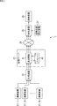
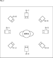
- FIG. 1 is a block diagram illustrating a configuration example of an image processing system to which the present technology is applied. It is a figure showing the example of arrangement of an imaging device.
- FIG. 3 is a diagram illustrating 3D model data.
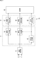
- FIG. 2 is a block diagram illustrating a configuration example of a first embodiment of a generation device.
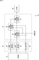
- FIG. 2 is a block diagram illustrating a configuration example of a first embodiment of the playback device.
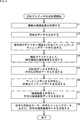
- 5 is a flowchart illustrating 3D model data generation processing according to the first embodiment.
- 5 is a flowchart illustrating a 3D model image generation process according to the first embodiment. It is a block diagram showing an example of composition of a 2nd embodiment of a generating device.
- FIG. 14 is a block diagram illustrating a configuration example of a second embodiment of the playback device.
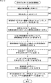
- 11 is a flowchart illustrating 3D model data generation processing according to the second embodiment.
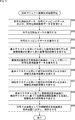
- 9 is a flowchart illustrating a 3D model image generation process according to the second embodiment.
- It is a block diagram showing an example of composition of a 3rd embodiment of a production device. It is a flow chart explaining 3D model data generation processing of a 3rd embodiment.
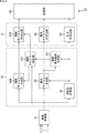
- FIG. 21 is a block diagram illustrating a configuration example of an embodiment of a computer to which the present technology is applied.
- FIG. 1 illustrates a configuration example of an image processing system to which the present technology is applied.
- the image processing system 1 of FIG. 1 includes a distribution side that generates and distributes 3D model image data from a plurality of captured images obtained from a plurality of imaging devices 21 and a 3D model image data transmitted from the distribution side. And a reproduction side for receiving and reproducing.
- the imaging devices 21-1 to 21-N (N> 1) are arranged at different positions on the outer periphery of the subject to capture an image of the subject, and generate a moving image obtained as a result. 22.
- FIG. 2 is an example in which eight imaging devices 21-1 to 21-8 are arranged. Each of the imaging devices 21-1 to 21-8 captures an image of a subject from a direction different from that of the other imaging devices 21. It is assumed that the position of each imaging device 21 on the world coordinate system is known.
- the moving image generated by each imaging device 21 is configured by a captured image (RGB image) including RGB wavelengths, but is a multispectral image including an IR (infrared) image. Is also good.
- the imaging devices 21 may perform imaging a plurality of times by changing imaging conditions such as an exposure condition, a light source position, or a light source color, and may supply a captured image obtained as a result to the generation device 22.
- each imaging device 21 is provided with a distance measurement sensor, measures the distance to the subject, and, in addition to the RGB captured image that is the texture information of the subject, sets the depth distance to the subject as a depth value, A depth image stored in association with each of the pixels may also be generated and supplied to the generation device 22. Further, the distance measurement sensor may exist independently of each imaging device 21.
- a distance measuring sensor for measuring a distance to a subject
- various methods such as a TOF (Timi Of Flight) method, a structured light method, a stereo matching method, and an SfM (Structure from Motion) method.
- a TOF method irradiates a target space with near-infrared light, receives reflected light from an object existing in the target space, and detects objects in the target space based on the time from irradiating near-infrared light to receiving reflected light.
- the stereo matching method is a method of obtaining a distance to a subject based on a parallax between two captured images of the subject captured from different positions.
- the SfM method is a method of detecting a depth by calculating and optimizing a relationship between images, such as alignment of feature points, using a plurality of captured images captured from different angles.
- each imaging device 21 also generates and generates information on the reflectance (albedo) of the object as an object, information on environmental light or shading, and additional information such as bump mapping, transmission mapping, normal mapping, and environmental mapping. It may be supplied to the device 22.
- Each imaging device 21 can be configured to arbitrarily combine the above-described image and additional information and supply the combination to the generation device 22.
- the generation device 22 includes a plurality of captured images supplied from each of the imaging devices 21-1 to 21-N, 3D shape data representing a 3D shape of the subject, mapping data obtained by mapping texture information of the subject in two dimensions, and Then, it generates area image data that is image data of a specific area in a plurality of captured images, and supplies the generated area image data to the distribution server 23.
- 3D shape data, the mapping data, and the area image data are collectively referred to as 3D model data.
- FIG. 3 is a diagram illustrating 3D model data generated by the generation device 22 and transmitted to the distribution server 23.
- captured images P1 to P8 are obtained by the imaging devices 21-1 to 21-8.
- the generation device 22 generates a 3D model of the subject from the captured images P1 to P8.
- the 3D model is composed of 3D shape data representing the 3D shape (geometry information) of the subject and mapping data obtained by mapping the texture information of the subject in two dimensions.
- the 3D shape data is, for example, data represented by a polygon mesh
- the mapping data is, for example, data represented by a UV map.
- the generation device 22 extracts one or more specific regions SP for which high image quality is desired from the captured images P1 to P8, and generates region image data. In the example of FIG. 3, three specific areas SP1 to SP3 including a face area of a person who is a subject are extracted from the captured images P1 to P8.
- the generation device 22 generates the 3D model data by obtaining the captured image once stored in a predetermined storage unit such as a data server instead of directly obtaining the captured image from the imaging devices 21-1 to 21-N. You can also.
- the distribution server 23 stores the 3D model data supplied from the generating device 22 and transmits the 3D model data to the reproducing device 25 via the network 24 in response to a request from the reproducing device 25. I do.
- the distribution server 23 includes a transmission / reception unit 41 and a storage 42.
- the transmission / reception unit 41 acquires the 3D model data supplied from the generation device 22 and stores the acquired 3D model data in the storage 42. In addition, the transmission / reception unit 41 transmits the 3D model data to the playback device 25 via the network 24 in response to a request from the playback device 25.
- the transmission / reception unit 41 can acquire the 3D model data from the storage 42 and transmit the acquired 3D model data to the playback device 25, or directly store the 3D model data supplied from the generation device 22 without storing the 3D model data in the storage 42. It can also be transmitted to the playback device 25 (real-time distribution).
- the network 24 is, for example, the Internet, a telephone network, a satellite communication network, various LANs (Local Area Network) including Ethernet (registered trademark), a WAN (WIde Area Network), and an IP-VPN (Internet Protocol-Virtual Network). And the like.
- LANs Local Area Network
- Ethernet registered trademark
- WAN Wide Area Network
- IP-VPN Internet Protocol-Virtual Network
- the reproducing device 25 generates (reproduces) a 3D model of the subject based on the 3D model data transmitted from the distribution server 23 via the network 24. More specifically, the playback device 25 pastes the texture information of the mapping data as a basic texture on the 3D shape represented by the 3D shape data, and further, attaches the area image of the specific area SP represented by the area image data to the auxiliary texture. To generate a 3D model of the subject. Then, the reproduction device 25 generates (reproduces) a 3D model image of the subject viewed from the viewer's viewing position supplied from the viewing position detection device 27 and supplies the 3D model image to the display device 26.
- the display device 26 displays the 3D model image supplied from the playback device 25.
- the viewer views the 3D model image displayed on the display device 26.
- the viewing position detecting device 27 detects the viewing position of the viewer and supplies the position to the reproducing device 25.
- the display device 26 and the viewing position detection device 27 may be configured as an integrated device.
- the display device 26 and the viewing position detection device 27 are configured by a head-mounted display, and detect the position where the viewer has moved, the movement of the head, and the like, and detect the viewing position of the viewer.
- the viewing position also includes the viewing direction of the viewer with respect to the 3D model generated by the playback device 25.
- the viewing position detection device 27 is configured, for example, with a controller or the like that operates the viewing position, and responds to the operation of the controller by the viewer.
- the playback position is supplied to the playback device 25, and the playback device 25 causes the display device 26 to display a 3D model image corresponding to the designated viewing position.
- the display device 26 or the viewing position detecting device 27 can also supply information relating to the display function of the display device 26, such as the image size and angle of view of the image displayed by the display device 26, to the playback device 25 as necessary.
- a free viewpoint image based on a basic texture independent of the viewpoint is used as an image in which the data amount is suppressed, and a specific image that the viewer pays attention to is specified.
- a high quality image is displayed by using an area image transmitted as an auxiliary texture. Thereby, high image quality can be realized while suppressing the amount of data to be transmitted.
- FIG. 4 is a block diagram illustrating a configuration example of the generation device 22 according to the first embodiment.
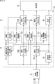
- the generation device 22 includes an image acquisition unit 61, a 3D shape calculation unit 62, a basic texture generation unit 63, an auxiliary texture generation unit 64, a shape encoding unit 65, a basic texture encoding unit 66, an auxiliary texture encoding unit 67, and The transmission unit 68 is configured.
- the 3D shape calculation unit 62, the basic texture generation unit 63, and the auxiliary texture generation unit 64 may be configured as one generation unit 71, and the shape encoding unit 65, the basic texture encoding unit 66, and the auxiliary texture
- the encoding unit 67 may be configured as one encoding unit 72.
- the image acquisition unit 61 acquires a plurality of captured images supplied from the plurality of imaging devices 21 and supplies the captured images to the 3D shape calculation unit 62, the basic texture generation unit 63, and the auxiliary texture generation unit 64.
- the 3D shape calculation unit 62 generates 3D shape data representing the 3D shape of the subject based on the plurality of captured images supplied from the image acquisition unit 61. For example, the 3D shape calculation unit 62 projects the silhouette of the subject at each viewpoint into a 3D space and sets the intersection area of the silhouette to a 3D shape, or a Multi view stereo using the consistency of texture information between viewpoints. For example, the 3D shape of the subject is acquired and 3D shape data is generated.
- the 3D shape calculation unit 62 needs camera parameters (internal parameters and external parameters) of each of the plurality of imaging devices 21, and the information thereof is It is input to the generation device 22 in advance and is known.
- the internal parameters are, for example, the focal length of the imaging device 21, the image center coordinates, the aspect ratio, and the like
- the external parameters are, for example, vectors indicating the direction and position of each imaging device 21 in the world coordinate system.
- the 3D shape calculation unit 62 includes, for example, a point cloud format in which the three-dimensional position of the subject is represented by a set of points, a 3D mesh format in which vertices (vertexes) called polygon meshes are connected to vertices, and voxels (voxel).
- 3D shape data can be generated in any format such as a voxel format represented by a set of called cubes.
- the 3D shape calculation unit 62 supplies the generated 3D shape data to the basic texture generation unit 63 and the shape encoding unit 65.
- the basic texture generation unit 63 generates a texture image that does not depend on the line-of-sight direction based on a plurality of captured images supplied from the image acquisition unit 61 and 3D shape data supplied from the 3D shape calculation unit 62. More specifically, the basic texture generation unit 63 generates mapping data in which texture information of a subject is two-dimensionally mapped. For example, the basic texture generation unit 63 performs UV mapping for mapping texture information to a polygon mesh, cube mapping for pasting on a cube, cylindrical coordinate projection mapping for pasting on a cylinder, parallel projection mapping for pasting parallel projection on the object surface, and the like. Generates mapping data mapped by any mapping method of The basic texture generator 63 supplies the generated mapping data to the basic texture encoder 66.
- the auxiliary texture generation unit 64 selects and cuts out (extracts) one or more specific regions SP from at least one of the plurality of captured images supplied from the image acquisition unit 61, so that the specific region SP is used as an auxiliary texture. Is generated.
- the auxiliary texture generation unit 64 supplies the area image of the specific area SP and the camera parameters of the imaging device 21 that has captured the area image to the auxiliary texture encoding unit 67.
- the auxiliary texture generating unit 64 may supply data converted to mapping data such as UV mapping, instead of the region image itself cut out from the captured image, to the auxiliary texture encoding unit 67 as a region image. In this case, no camera parameters are required.
- the shape of the selected specific area SP an arbitrary shape such as a rectangle, a circle, and a polygon can be set. Further, the shape may be determined by a free curve. Further, the number of specific regions SP selected for one captured image may be one (single) or plural.
- the size of the specific area SP to be selected may be a fixed size that is set in advance, or may be, for example, a size that is adaptively changed according to the size of an object of interest, such as a face area.
- the auxiliary texture generation unit 64 may select the specific area SP by a manual operation for each captured image, for example, by designating the specific area using a mouse, or automatically (without a user operation). SP may be selected.
- a method of automatically selecting a specific area SP there is a method of detecting a face area of a person as a subject or a specific object such as a person or a car by a recognition process.
- a plurality of types of texture images such as mapping data of a bump map expressing a texture (pores and wrinkles) in a human skin region are supplied from the imaging device 21 as additional information of the subject as well as the RGB captured image.
- the auxiliary texture generation unit 64 selects the specific area SP for each of the plurality of texture images, and supplies the specific area SP to the auxiliary texture encoding unit 67.
- By transmitting a plurality of types of texture images for the specific area SP it is possible to expect an improvement in the texture when reproduced and displayed by the reproducing device 25.
- a plurality of types of texture images having different exposure conditions are received from the imaging device 21 as the texture information of the subject, a wide dynamic range image with an increased dynamic range can be generated on the reproduction device 25 side. Thus, an improvement in the image quality when reproduced and displayed by the reproducing device 25 can be expected.
- the auxiliary texture generation unit 64 includes one of the plurality of captured images.
- the specific region SP of the plurality of captured images may be selected by reflecting the specific region SP selected by the manual operation or the recognition process in the corresponding region of the captured image captured at another imaging position.
- the area selected in one captured image first captured image
- second captured image the same position in the world coordinate system may be selected.
- the same subject may be selected with different coordinate positions.
- the selected specific area SP can be continuously selected for captured images that are continuous in the time direction, and can be made to track or change the size with reference to a predetermined object. Can be.
- the auxiliary texture generation unit 64 When the position and size of the specific area SP are changed depending on the captured image, the auxiliary texture generation unit 64 performs information on the position and size of the specific area SP, such as the coordinates of the upper left corner of the specific area SP and the specific area SP.
- the width and height of the SP can be transmitted as meta information.
- the auxiliary texture generation unit 64 may use, for example, an exposure time or a gain value.
- information for adjusting the brightness of a plurality of captured images can be transmitted as meta information.
- the shape encoding unit 65 encodes the 3D shape data supplied from the 3D shape calculation unit 62 by a predetermined encoding method, and supplies the encoded 3D shape data obtained as a result to the transmission unit 68.
- the encoding method is not particularly limited, and any method can be adopted.
- an encoding compression method called “Draco” developed by Google can be adopted (https://mag.osdn.jp/17/01/16/144500).
- the shape encoding unit 65 may encode and transmit information necessary for calculating the 3D shape. For example, as information necessary for calculating the 3D shape by Visual Hull, the silhouette image and camera parameters are encoded and transmitted, or instead of sending the 3D shape data in the point cloud format, the depth image and camera parameters are encoded. You may send it.
- the basic texture encoding unit 66 encodes the mapping data supplied from the basic texture generation unit 63 by a predetermined encoding method, and supplies the resulting encoded mapping data to the transmission unit 68.
- the encoding method is not particularly limited, and any method can be adopted.
- HEVC High Efficiency Video Coding
- HEVC High Efficiency Video Coding
- the auxiliary texture encoding unit 67 encodes the area image of the specific area SP supplied from the auxiliary texture generation unit 64 by a predetermined encoding method, and supplies the resulting encoded area image data to the transmission unit 68.
- the encoding method is not particularly limited, and an arbitrary method such as an MPEG2 method or an HEVC (High Efficiency Video Coding) method can be adopted.
- the camera parameters of the imaging device 21 that has captured the area image are stored as metadata in the encoded area image data, for example.
- the camera parameter may be transmitted for each frame, or may be transmitted only at the time of change after being transmitted in the first frame of the moving image.
- the MPEG2 method or the H.264 / AVC method By performing predictive encoding, which is also used in encoding, compression efficiency can be improved.
- the transmitting unit 68 converts the encoded 3D shape data, the encoded mapping data, and the encoded area image data supplied from the shape encoding unit 65, the basic texture encoding unit 66, and the auxiliary texture encoding unit 67. , To the distribution server 23.
- FIG. 5 is a block diagram illustrating a configuration example of the playback device 25 according to the first embodiment.
- the playback device 25 includes a receiving unit 81, a shape decoding unit 82, a basic texture decoding unit 83, an auxiliary texture decoding unit 84, a viewing viewpoint image generation unit 85, a viewing viewpoint image generation unit 86, a viewing viewpoint image synthesis unit 87, and an output. It is constituted by a unit 88.
- the shape decoding unit 82, the basic texture decoding unit 83, and the auxiliary texture decoding unit 84 may be configured as one decoding unit 91, and the viewing viewpoint image generation unit 85, the viewing viewpoint image generation unit 86, and the viewing viewpoint
- the image combining unit 87 may be configured as one combining unit 92.
- the decoding unit 91 decodes the encoded 3D shape data, the encoded mapping data, and the encoded area image data.
- the combining unit 92 combines the 3D shape data, the mapping data, and the region image data to generate an image viewed from a predetermined viewing position (viewing viewpoint combined image).
- the receiving unit 81 requests the distribution server 23 for the 3D model data at a predetermined timing, and in response to the request, the 3D model data transmitted from the distribution server 23, more specifically, the encoded 3D shape data, Receiving the encoded mapping data and the encoded area image data.
- the receiving unit 81 supplies the encoded 3D shape data to the shape decoding unit 82, supplies the encoded mapping data to the basic texture decoding unit 83, and supplies the encoded area image data to the auxiliary texture decoding unit 84.
- the shape decoding unit 82 decodes the encoded 3D shape data supplied from the receiving unit 81 by a method corresponding to the encoding method of the generation device 22.
- the shape decoding unit 82 supplies the 3D shape data obtained by decoding to the viewing viewpoint image generation unit 85 and the viewing viewpoint image generation unit 86.
- the basic texture decoding unit 83 decodes the coded mapping data supplied from the receiving unit 81 by a method corresponding to the coding method of the generation device 22.
- the basic texture decoding unit 83 supplies the mapping data obtained by decoding to the viewing viewpoint image generating unit 85.
- the auxiliary texture decoding unit 84 decodes the coded area image data supplied from the receiving unit 81 by a method corresponding to the coding method of the generation device 22.
- the auxiliary texture decoding unit 84 supplies one or more region images obtained by decoding to the viewing viewpoint image generating unit 86.
- the viewing position of the viewer is supplied from the viewing position detection device 27 (FIG. 1) to the viewing viewpoint image generation unit 85 and the viewing viewpoint image generation unit 86.
- the viewing viewpoint image generation unit 85 attaches the texture image of the mapping data supplied from the basic texture decoding unit 83 to the surface of the 3D shape of the 3D shape data supplied from the shape decoding unit 82, thereby forming a 3D model of the subject. Generate Then, the viewing viewpoint image generation unit 85 outputs the viewing viewpoint image (first viewing / listening image) which is a 2D image when the generated 3D model of the subject is viewed from the viewing position supplied from the viewing position detection device 27 (FIG. 1). (Viewpoint image) is generated (rendered). The viewing viewpoint image generation unit 85 supplies the generated viewing viewpoint image to the viewing viewpoint image synthesis unit 87.
- mapping method of the mapping data is the UV mapping
- the texture image of the mapping data can be pasted on the surface of the 3D shape.
- mapping method is parallel projection mapping, cube mapping, or the like
- the texture image pasting position can be geometrically determined from the 3D shape of the subject and the projection method.
- the viewing viewpoint image generation unit 86 attaches one or more region images supplied from the auxiliary texture decoding unit 84 to the surface of the 3D shape corresponding to the 3D shape data supplied from the shape decoding unit 82, and thereby Generate a 3D model.
- the viewing viewpoint image generation unit 86 geometrically determines the pasting position of the area image from the area image and the camera parameter.
- the area image data is composed of mapping data such as UV mapping, a texture image of the mapping data can be pasted on the surface of the 3D shape according to the mapping method, similarly to the basic texture.
- the viewing viewpoint image generation unit 86 is a viewing viewpoint image (second viewing viewpoint image) that is a 2D image when the generated 3D model of the subject is viewed from the viewing position supplied from the viewing position detection device 27 (FIG. 1). ) Is generated (rendered). Since the area image data is data of an image of only a specific area of the subject, there are areas (pixels) in the viewing viewpoint image generated by the viewing viewpoint image generation unit 86 where no texture is attached. The viewing viewpoint image generation unit 86 supplies the generated viewing viewpoint image to the viewing viewpoint image synthesis unit 87.
- the viewing viewpoint image based on the basic texture generated by the viewing viewpoint image generation unit 85 is referred to as a viewing viewpoint basic image
- the viewing viewpoint image based on the auxiliary texture generated by the viewing viewpoint image generation unit 86 is referred to as a viewing viewpoint image.
- the viewing viewpoint image generation unit 86 If the area image data includes two or more area images, the viewing viewpoint image generation unit 86 generates a viewing viewpoint auxiliary image for each area image. At this time, the viewing viewpoint image generation unit 86 generates and adds, for each pixel of the viewing viewpoint auxiliary image, the reliability required for the viewing viewpoint image synthesis unit 87 to synthesize a plurality of viewing viewpoint auxiliary images.
- the reliability can be generated, for example, as follows.
- the reliability of a pixel on which a texture is not pasted in the viewing viewpoint auxiliary image is set to 0, and is set as an invalid area. Thereby, it is possible to determine the region where the region image (texture) is pasted and the region where the region image (texture) is not pasted in the viewing viewpoint auxiliary image.
- the viewing viewpoint image generation unit 86 For each pixel to which the region image is pasted in the viewing viewpoint auxiliary image, for example, the viewing viewpoint image generation unit 86 increases the reliability of the viewing viewpoint auxiliary image as the pixel is closer to the imaging device 21 that has captured the region image. Can be set. As a result, the image becomes coarser as the distance from the imaging device 21 to the subject increases, so that it is possible to select the pixels of the viewing viewpoint auxiliary image cut out from the captured image captured from a position close to the subject.
- the viewing viewpoint image generation unit 86 sets the viewing viewpoint auxiliary image such that the closer the angle between the imaging direction of the imaging device 21 that has captured the region image and the normal of the subject shape of each pixel to the pixel is closer to 90 degrees. Can be set small. As a result, the region image that is obliquely oriented with respect to the imaging device 21 is stretched when pasting, so that it is possible to select a pixel of the viewing viewpoint auxiliary image that faces as much as possible.
- the viewing viewpoint image generation unit 86 can set the reliability of the viewing viewpoint auxiliary image to be higher for a pixel closer to the center of the captured image captured by the imaging device 21.
- the image is blurred at the outer peripheral portion (the position where the image height is high) of the imaging range of the imaging device 21 by the distortion correction.
- the above is a method of setting the reliability for each pixel of the viewing viewpoint auxiliary image.
- the reliability may be set for each viewing viewpoint auxiliary image.
- the viewing viewpoint image generation unit 86 compares the SN ratios of the region images, sets a large reliability of the viewing viewpoint auxiliary image with little noise, or sets the reliability of the viewing viewpoint auxiliary image cut out from the captured image with high resolution.
- the degree can be set higher. This makes it possible to select a viewing viewpoint auxiliary image with little noise or a high resolution viewing viewpoint auxiliary image.
- the viewpoint image generation unit 85 and the viewing viewpoint image generation unit 86 can generate a viewing viewpoint image based on the information.
- the viewing viewpoint image combining unit 87 combines the viewing viewpoint basic image based on the basic texture supplied from the viewing viewpoint image generating unit 85 and the viewing viewpoint auxiliary image based on the auxiliary texture supplied from the viewing viewpoint image generating unit 86. , And a resultant viewing viewpoint composite image is generated.
- the viewing viewpoint basic image based on the basic texture is directly used as the viewing viewpoint composite image.
- the viewing viewpoint auxiliary image is adopted, and is used as the viewing viewpoint combined image.
- the viewing viewpoint auxiliary image with the highest reliability is adopted and is set as a viewing viewpoint combined image.
- the viewing viewpoint image combining unit 87 supplies the generated viewing viewpoint combined image to the output unit 88 as a 3D model image.
- the output unit 88 converts the viewing viewpoint composite image as the 3D model image into a signal format corresponding to the input format of the display device 26 and outputs the signal.
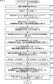
- step S1 the image acquisition unit 61 acquires a plurality of captured images supplied from the plurality of imaging devices 21 and sends the acquired images to the 3D shape calculation unit 62, the basic texture generation unit 63, and the auxiliary texture generation unit 64. Supply.
- step S2 the 3D shape calculation unit 62 generates 3D shape data representing the 3D shape of the subject based on the plurality of captured images supplied from the image acquisition unit 61.
- the 3D shape calculation unit 62 supplies the generated 3D shape data to the basic texture generation unit 63 and the shape encoding unit 65.
- step S3 the basic texture generation unit 63 converts the texture information of the subject into a two-dimensional image based on the plurality of captured images supplied from the image acquisition unit 61 and the 3D shape data supplied from the 3D shape calculation unit 62. Generate mapped data.
- the basic texture generator 63 supplies the generated mapping data to the basic texture encoder 66.
- step S4 the auxiliary texture generation unit 64 generates a region image of the specific region SP as an auxiliary texture by selecting and cutting out the specific region SP from at least one of the plurality of captured images.
- the auxiliary texture generation unit 64 supplies the area image of the specific area SP and the camera parameters of the imaging device 21 that has captured the area image to the auxiliary texture encoding unit 67 as area image data.
- the camera parameters may always be sent for each frame, or may be sent only at the time of change after being sent in the first frame of a moving image.
- steps S2 and S3 and the processing of S4 can be executed in any order, and can also be executed in parallel.
- step S5 the shape encoding unit 65 encodes the 3D shape data supplied from the 3D shape calculation unit 62 by a predetermined encoding method, generates encoded 3D shape data, and supplies the encoded data to the transmission unit 68. .
- step S6 the basic texture encoding unit 66 encodes the mapping data supplied from the basic texture generating unit 63 by a predetermined encoding method, generates encoded mapping data, and supplies the encoded mapping data to the transmitting unit 68.
- the auxiliary texture encoding unit 67 encodes the area image supplied from the auxiliary texture generation unit 64 by a predetermined encoding method, generates encoded area image data, and supplies the encoded area image data to the transmission unit 68.
- predictive encoding which is also used in encoding of the MPEG2 system or the H.264 / AVC system, is performed on a plurality of area images adjacent in the time direction.
- the camera parameters of the imaging device 21 that has captured the area image are stored as metadata in the encoded area image data, for example.
- steps S5 to S7 can be executed in an arbitrary order, and can also be executed in parallel.
- step S8 the transmitting unit 68 transmits the encoded 3D shape data, the encoded mapping data, and the encoded area image data to the distribution server 23.
- steps S1 to S8 are repeatedly executed while the captured images are supplied from each of the plurality of imaging devices 21. Then, when the supply of the captured image ends, the 3D model data generation processing ends.
- the receiving unit 81 requests the distribution server 23 for 3D model data, and the 3D model data transmitted from the distribution server 23 in response to the request, more specifically, the encoded 3D shape.
- Data, coded mapping data, and coded area image data are received.
- the receiving unit 81 supplies the encoded 3D shape data to the shape decoding unit 82, supplies the encoded mapping data to the basic texture decoding unit 83, and supplies the encoded area image data to the auxiliary texture decoding unit 84.
- step S22 the shape decoding unit 82 decodes the encoded 3D shape data supplied from the receiving unit 81 by a method corresponding to the encoding method of the generation device 22.
- the 3D shape data obtained by decoding is supplied to the viewing viewpoint image generation unit 85 and the viewing viewpoint image generation unit 86.
- step S23 the basic texture decoding unit 83 decodes the coded mapping data supplied from the receiving unit 81 by a method corresponding to the coding method of the generation device 22.
- the basic texture decoding unit 83 supplies the mapping data obtained by decoding to the viewing viewpoint image generating unit 85.
- step S ⁇ b> 24 the auxiliary texture decoding unit 84 decodes the coded area image data supplied from the receiving unit 81 using a method corresponding to the coding method of the generation device 22.
- One or more region images obtained by decoding are supplied to the viewing viewpoint image generation unit 86.
- steps S22 to S24 can be executed in an arbitrary order, and can also be executed in parallel.
- the viewing viewpoint image generation unit 85 generates a 3D model of the subject using the basic texture and generates a viewing viewpoint basic image. More specifically, the viewing viewpoint image generation unit 85 pastes the texture image of the mapping data supplied from the basic texture decoding unit 83 on the 3D shape surface of the 3D shape data supplied from the shape decoding unit 82. Generates a 3D model of the subject. Then, the viewing viewpoint image generation unit 85 generates a viewing viewpoint basic image that is a 2D image when the generated 3D model of the subject is viewed from the viewing position supplied from the viewing position detection device 27. The generated viewing viewpoint basic image is supplied to the viewing viewpoint image synthesis unit 87.
- the viewing viewpoint image generation unit 86 generates a 3D model of the subject using the auxiliary texture, and generates a viewing viewpoint auxiliary image. More specifically, the viewing viewpoint image generation unit 86 pastes one or more region images supplied from the auxiliary texture decoding unit 84 on the surface of the 3D shape corresponding to the 3D shape data supplied from the shape decoding unit 82. By attaching, a 3D model of the subject is generated.
- the viewing viewpoint image generation unit 86 generates a viewing viewpoint auxiliary image that is a 2D image when the generated 3D model of the subject is viewed from the viewing position supplied from the viewing position detection device 27.
- the generated viewing viewpoint auxiliary image is supplied to the viewing viewpoint image synthesis unit 87.
- steps S25 and S26 can be executed in the reverse order, or can be executed in parallel.
- the viewing viewpoint image synthesizing unit 87 converts the viewing viewpoint basic image based on the basic texture supplied from the viewing viewpoint image generating unit 85 and the viewing viewpoint auxiliary image based on the auxiliary texture supplied from the viewing viewpoint image generating unit 86. Are combined to generate a viewing viewpoint composite image.
- the generated viewing viewpoint composite image is supplied to the output unit 88 as a 3D model image.
- step S28 the output unit 88 outputs the viewing viewpoint composite image as a 3D model image to the display device 26 and causes the display device 26 to display it.
- steps S21 to S28 are repeatedly executed while the 3D model data is supplied from the distribution server 23. Then, when the supply of the 3D model data ends, the 3D model image generation processing ends.
- the generation device 22 includes a plurality of imaging devices together with 3D shape data representing a 3D shape of a subject and mapping data obtained by mapping texture information of the subject in two dimensions.
- Region image data of a specific region SP in which only a region where high image quality is particularly desired is selected from the image is generated.
- the playback device 25 generates a display image to be presented to the viewer by combining the 3D model image generated using the 3D shape data and the mapping data with the region image of the region image data.
- the viewing viewpoint image generation unit 86 converts all the generated viewing viewpoint auxiliary images into the viewing viewpoint image. This is supplied to the synthesizing unit 87, and the viewing viewpoint image synthesizing unit 87 employs the viewing viewpoint auxiliary image with the highest reliability and synthesizes it with the viewing viewpoint basic image to generate a viewing viewpoint synthesized image.
- the viewing viewpoint image generating unit 86 supplies only the viewing viewpoint auxiliary image with the highest reliability to the viewing viewpoint image combining unit 87 among all the viewing viewpoint auxiliary images generated, and the viewing viewpoint image combining unit 87
- the viewing viewpoint basic image is used as it is to provide a viewing viewpoint composite image
- the viewing viewpoint auxiliary image is used. It may be an image.
- the viewing viewpoint image synthesizing unit 87 generates a viewing viewpoint auxiliary combined image obtained by combining the plurality of viewing viewpoint auxiliary images supplied from the viewing viewpoint image generation unit 86 by weighting and adding them according to the reliability.
- the auxiliary combined image and the viewing viewpoint basic image based on the basic texture may be combined to generate a viewing viewpoint combined image.
- the viewing viewpoint image generation unit 85 and the viewing viewpoint image generation unit 86 generate a viewing viewpoint basic image and a viewing viewpoint auxiliary image when viewed from the viewing position, and thereafter,
- the viewing viewpoint image combining unit 87 combines the viewing viewpoint base image and the viewing viewpoint auxiliary image. That is, after the rendering, the synthesis of the viewing viewpoint images was performed.
- rendering may be performed after the viewing viewpoint images are combined first. That is, the viewing viewpoint image generation unit 85 supplies the viewing viewpoint image synthesis unit 87 with the 3D model of the subject generated by pasting the texture image of the mapping data on the surface of the 3D shape of the 3D shape data, and outputs the viewing viewpoint image.
- the generating unit 86 supplies the viewing viewpoint image synthesizing unit 87 with the 3D model of the subject generated by pasting the region image of the region image data on the surface of the 3D shape corresponding to the 3D shape data.
- the viewing viewpoint image synthesis unit 87 combines the 3D model from the viewing viewpoint image generation unit 85 and the 3D model from the viewing viewpoint image generation unit 86, and displays the synthesized 3D model when viewed from the viewing position. Generate an image.
- the viewing position supplied from the viewing position detection device 27 (FIG. 1) is supplied to the viewing viewpoint image combining unit 87.
- the playback device 25 acquires 3D model data corresponding to all viewing positions, The 3D model image corresponding to the viewing position supplied from 27 is displayed.
- the playback device 25 outputs the 3D model data of only a partial area required for display from the viewing position.
- the request can be obtained from the distribution server 23 and displayed.
- FIG. 8 is a block diagram illustrating a configuration example of the generation device 22 according to the second embodiment.
- the generating apparatus 22 according to the second embodiment shown in FIG. 8 has an auxiliary viewpoint image generating unit 101 and an auxiliary texture control unit 102 newly added. Further, the auxiliary texture generation unit 64 and the auxiliary texture encoding unit 67 are changed to an auxiliary texture generation unit 64A and an auxiliary texture encoding unit 67A. The other points are the same as in the first embodiment.
- the auxiliary viewpoint image generation unit 101 is supplied with 3D shape data representing the 3D shape of the subject from the 3D shape calculation unit 62, and is supplied with the mapping data obtained by mapping the texture information of the subject in two dimensions from the basic texture generation unit 63. Is done.
- the auxiliary viewpoint image generation unit 101 generates a 3D model of the subject by pasting a texture image of the mapping data on the surface of the 3D shape of the 3D shape data. Then, the auxiliary viewpoint image generation unit 101 generates a captured viewpoint image that is a 2D image when the generated 3D model of the subject is viewed from the position of each imaging device 21. The auxiliary viewpoint image generation unit 101 supplies the generated captured viewpoint image to the auxiliary texture control unit 102.
- the auxiliary viewpoint image generation unit 101 and the viewing viewpoint image generation unit 85 of the playback device 25 The same processing is performed.
- a general method of 3D CG processing for calculating a 2D image from the auxiliary viewpoint of the 3D model can be used to generate the imaging viewpoint image using the position of each imaging device 21 as an auxiliary viewpoint.
- the processing need not be the same as that of the image generation unit 85.
- the auxiliary viewpoint image generation unit 101 converts the captured viewpoint image delayed by several frames into the auxiliary texture control unit 102 May be adopted.
- the input image from the image acquisition unit 61 to the auxiliary texture generation unit 64A and the auxiliary viewpoint The adjustment may be made so that the image input from the image generation unit 101 to the auxiliary texture control unit 102 is an image captured at the same timing.
- the auxiliary texture control unit 102 is supplied with the captured viewpoint image as viewed from the position of each imaging device 21 from the auxiliary viewpoint image generation unit 101, and is also captured by each imaging device 21 from the image acquisition unit 61. A captured image is provided.
- the auxiliary texture control unit 102 determines whether or not to encode a region image for each of the one or more specific regions SP selected by the auxiliary texture generation unit 64A. Specifically, the auxiliary texture control unit 102 determines, for each of the one or more specific areas SP, the captured viewpoint image generated by the auxiliary viewpoint image generation unit 101 and the actual captured image supplied from the image acquisition unit 61. The difference is calculated, and if the difference is equal to or greater than a predetermined threshold, it is determined that the region image is to be encoded. For the difference, for example, a sum of absolute differences between the captured viewpoint image and the actual captured image, SSIM (Structural SIMlicarity), or the like is used.
- SSIM Structuretural SIMlicarity
- the auxiliary texture control unit 102 instructs the auxiliary texture generation unit 64A to generate an area image for the specific area SP determined to be encoded.
- the auxiliary texture control unit 102 supplies the captured viewpoint image of the specific area SP instructed to generate the area image to the auxiliary texture generation unit 64A to the auxiliary texture encoding unit 67A.
- the auxiliary texture generation unit 64A generates an area image of the specific area SP instructed to be generated by the auxiliary texture control unit 102, and sends the area image to the auxiliary texture encoding unit 67A together with the camera parameters of the imaging device 21 that has captured the area image. Supply.
- the other points are the same as those of the auxiliary texture generation unit 64 of the first embodiment.
- the selection of the specific area SP is performed manually or automatically by the auxiliary texture generation unit 64A, and information for identifying the specific area SP is supplied to the auxiliary texture control unit 102.
- the auxiliary texture control unit 102 may perform the processing and supply the result to the auxiliary texture generation unit 64A. Further, both the auxiliary texture generation unit 64A and the auxiliary texture control unit 102 may perform the processing.
- the auxiliary texture encoding unit 67A is supplied with the captured viewpoint image of the specific area SP for which the area image data is determined to be generated by the auxiliary texture control unit 102 from the auxiliary texture control unit 102, and the specific area SP Are supplied from the auxiliary texture generation unit 64A.
- the auxiliary texture encoding unit 67A encodes the area image of the specific area SP supplied from the auxiliary texture generation unit 64A by a predetermined encoding method, and supplies the resulting encoded area image data to the transmission unit 68. .
- the auxiliary texture encoding unit 67A sets the captured viewpoint image of the specific area SP supplied from the auxiliary texture control unit 102 as one of the candidates of the predicted image, and determines the captured viewpoint image with the area image supplied from the auxiliary texture generation unit 64A. Prediction coding for coding the difference may be performed, or coding may be performed using a captured image whose time direction is earlier or later as a predicted image, as in the first embodiment.
- the auxiliary texture encoding unit 67A supplies the transmission unit 68 with encoded area image data encoded using the predicted image.
- FIG. 9 is a block diagram illustrating a configuration example of the second embodiment of the playback device 25.
- FIG. 9 parts corresponding to those in the first embodiment shown in FIG. 5 are denoted by the same reference numerals, and description of parts common to the first embodiment will be omitted as appropriate, and different parts will be described. The description will be made by focusing on.
- the reproducing apparatus 25 according to the second embodiment of FIG. 9 has a new auxiliary viewpoint image generating unit 121. Also, the auxiliary texture decoding unit 84 has been changed to an auxiliary texture decoding unit 84A. The other points are the same as in the first embodiment.
- ⁇ External parameters of each imaging device 21 are supplied to the auxiliary viewpoint image generation unit 121 from the auxiliary texture decoding unit 84A. Further, the 3D shape data is supplied from the shape decoding unit 82 to the auxiliary viewpoint image generation unit 121, and the mapping data is supplied from the basic texture decoding unit 83.
- the auxiliary viewpoint image generation unit 121 generates a 3D model of the subject by pasting a texture image of the mapping data on the surface of the 3D shape of the 3D shape data. Then, the auxiliary viewpoint image generation unit 121 generates a captured viewpoint image that is a 2D image when the generated 3D model of the subject is viewed from the position of the imaging device 21 supplied from the auxiliary texture decoding unit 84A.
- the auxiliary viewpoint image generation unit 121 performs the same processing as the viewing viewpoint image generation unit 85 except that the position of the generated viewpoint is not the viewing position of the viewer but the position of each imaging device 21. Do.
- the auxiliary viewpoint image generation unit 121 supplies the generated one or more captured viewpoint images to the auxiliary texture decoding unit 84A.
- the auxiliary texture decoding unit 84A supplies the external parameters of the imaging device 21 included in the area image data to the auxiliary viewpoint image generation unit 121.
- the auxiliary texture decoding unit 84A decodes the coded area image data using the captured viewpoint image supplied from the auxiliary viewpoint image generation unit 121 as one of the candidates for the predicted image, and obtains a difference image. Then, the auxiliary texture decoding unit 84A performs the same processing as in the first embodiment from the difference image obtained by the decoding and the image used as the prediction image (the captured viewpoint image or the image preceding or following in the time direction). , One or more region images are generated and supplied to the viewing viewpoint image generation unit 86.
- Steps S41 to S43 are the same as steps S1 to S3 in FIG. 6 in the first embodiment, and a description thereof will be omitted.
- the auxiliary viewpoint image generation unit 101 generates a 3D model of the subject, and generates a captured viewpoint image obtained by viewing the generated 3D model from the position of each imaging device 21. More specifically, the auxiliary viewpoint image generation unit 101 generates a 3D model of the subject by pasting the texture image of the mapping data on the surface of the 3D shape of the 3D shape data. Then, the auxiliary viewpoint image generation unit 101 generates a captured viewpoint image that is a 2D image when the generated 3D model of the subject is viewed from the position of each imaging device 21. The generated captured viewpoint image is supplied to the auxiliary texture control unit 102.
- the auxiliary texture control unit 102 determines whether to encode a region image for each of the one or more specific regions SP selected by the auxiliary texture generation unit 64A. Specifically, the auxiliary texture control unit 102 determines, for each of the one or more specific areas SP, the captured viewpoint image generated by the auxiliary viewpoint image generation unit 101 and the actual captured image supplied from the image acquisition unit 61. The difference is calculated, and if the difference is equal to or greater than a predetermined threshold, it is determined that the region image is to be encoded. The auxiliary texture control unit 102 instructs the auxiliary texture generation unit 64A to generate an area image for the specific area SP determined to be encoded. The auxiliary texture control unit 102 supplies the captured viewpoint image of the specific area SP instructed to generate the area image to the auxiliary texture generation unit 64A to the auxiliary texture encoding unit 67A.
- the auxiliary texture generation unit 64A generates an area image of the specific area SP determined to encode the captured image. Specifically, the auxiliary texture generation unit 64A generates an area image of the specific area SP instructed to be generated by the auxiliary texture control unit 102. Then, the area image of the specific area SP as the auxiliary texture and the camera parameters of the imaging device 21 that has captured the area image are supplied to the auxiliary texture encoding unit 67A as area image data.
- the camera parameters may always be sent for each frame, or may be sent only at the time of change after being sent in the first frame of a moving image.
- Steps S47 and S48 are the same as steps S5 and S6 in FIG. 6 in the first embodiment, and a description thereof will be omitted.
- the auxiliary texture encoding unit 67A encodes the area image of the specific area SP supplied from the auxiliary texture generation unit 64A by a predetermined encoding method, generates encoded area image data, and 68.
- the auxiliary texture encoding unit 67A uses the captured viewpoint image of the specific area SP supplied from the auxiliary texture control unit 102 as one of the candidates for the prediction image, and uses the area image supplied from the auxiliary texture generation unit 64A as a candidate for the predicted image.
- Predictive coding for encoding can be performed.
- the camera parameters of the imaging device 21 that has captured the area image are stored as metadata in the encoded area image data, for example.
- step S50 the transmission unit 68 transmits the encoded 3D shape data, the encoded mapping data, and the encoded area image data to the distribution server 23.
- Steps S61 to S63 are the same as steps S21 to S23 in FIG. 6 in the first embodiment, and a description thereof will be omitted.
- the auxiliary viewpoint image generation unit 121 generates a 3D model of the subject using the basic texture, and generates a captured viewpoint image of the generated 3D model viewed from the position of the imaging device 21. That is, the external parameters of the imaging device 21 included in the area image data are supplied from the auxiliary texture decoding unit 84A to the auxiliary viewpoint image generating unit 121.
- the auxiliary viewpoint image generation unit 121 generates a 3D model of the subject by pasting the texture image of the mapping data on the surface of the 3D shape of the 3D shape data. Then, the auxiliary viewpoint image generation unit 121 generates a captured viewpoint image that is a 2D image when the generated 3D model of the subject is viewed from the position of the imaging device 21.
- the generated captured viewpoint image is supplied to the auxiliary texture decoding unit 84A.
- step S65 the auxiliary texture decoding unit 84A decodes the coded area image data using the captured viewpoint image supplied from the auxiliary viewpoint image generation unit 121 as one of the candidates for the predicted image, and obtains a difference image. Then, the auxiliary texture decoding unit 84A generates one or more region images similar to the first embodiment from the difference image obtained by the decoding and the image used as the prediction image, and generates a viewing viewpoint image. To the unit 86.
- Steps S66 to S69 are the same as steps S25 to S28 in FIG. 6 in the first embodiment, and a description thereof will be omitted.
- the generation device 22 generates a captured viewpoint image from the viewpoint of the imaging device 21 that is the same as the region image of the specific region SP generated as the auxiliary texture.
- An area image is generated only for the specific area SP where the difference between the image and the actual captured image is large, and transmitted to the distribution server 23.
- the playback device 25 When the playback device 25 generates a viewing viewpoint basic image when the 3D model of the subject generated using the basic texture is viewed from the viewing position, and when the 3D model of the subject generated using the auxiliary texture is viewed from the viewing position. Is similar to the first embodiment in that the viewing viewpoint auxiliary image is generated, and the viewing viewpoint basic image and the viewing viewpoint auxiliary image are combined to generate the viewing viewpoint combined image. Is data encoded using the captured viewpoint image as one of the candidates for the predicted image.
- the effect of the auxiliary texture image is small in the area where the difference is small (the area where the basic texture is sufficient).
- the data amount can be reduced and the compression efficiency can be improved.
- the region image (difference) is not transmitted for the specific region SP in which the difference between the captured viewpoint image and the actual captured image is small, but regardless of the size of the difference. Instead, an area image may be generated and transmitted. Even in this case, since the prediction encoding for encoding the difference is performed, a high-quality free viewpoint image can be realized while suppressing the amount of transfer data and the amount of calculation.
- the area size of the specific area SP is increased, or another area having a large difference is detected. Then, the number of specific regions SP may be increased by adding them as specific regions SP. Thereby, the image quality at the time of reproduction can be further improved.
- FIG. 12 is a block diagram illustrating a configuration example of the generating device 22 according to the third embodiment.
- the generating apparatus 22 according to the third embodiment of FIG. 12 includes a new auxiliary viewpoint high-quality image generating unit 141, an auxiliary texture control unit 142, and an auxiliary texture generating unit 143. Further, the auxiliary texture encoding section 67A has been changed to an auxiliary texture encoding section 67B. The other points are the same as in the second embodiment.
- a plurality of captured images are supplied from the image acquisition unit 61 to the auxiliary viewpoint high-quality image generation unit 141, and 3D shape data representing the 3D shape of the subject is supplied from the 3D shape calculation unit 62.
- the auxiliary-viewpoint high-quality image generation unit 141 generates a high-quality captured image whose characteristics are more improved than those of a captured image captured by the imaging device 21 alone.
- the auxiliary viewpoint high-quality image generation unit 141 generates a high-quality captured image by generating a viewpoint composite image obtained by combining a plurality of captured images supplied from the image acquisition unit 61.
- the auxiliary viewpoint high-quality image generation unit 141 increases the resolution as a high-quality captured image, such as changing the resolution from full HD to 4k by integrating sampling points having different spatial phases from the captured image of the imaging device 21 alone. It generates a resolution captured image, a low noise captured image with reduced noise, a wide dynamic range captured image with an expanded dynamic range, a wide angle captured image with an expanded FOV (angle of view), and the like.
- the auxiliary viewpoint high-quality image generation unit 141 generates a high-quality 3D model of the subject by pasting the generated high-quality captured image on the 3D shape surface of the 3D shape data. Then, the auxiliary viewpoint high quality image generation unit 141 generates a high quality imaging viewpoint image which is a 2D image when the generated high quality 3D model of the subject is viewed from the position of each imaging device 21. The auxiliary viewpoint high quality image generation unit 141 supplies the generated high quality captured viewpoint image to the auxiliary texture control unit 142 and the auxiliary texture generation unit 143.
- the auxiliary texture control unit 142 acquires a high-quality captured viewpoint image from the auxiliary viewpoint high-quality image generation unit 141, and acquires a captured viewpoint image viewed from the position of each imaging device 21 from the auxiliary viewpoint image generation unit 101. I do.
- the auxiliary texture control unit 142 determines whether to encode a high-quality captured viewpoint image for each of the one or more specific regions SP. Specifically, the auxiliary texture control unit 142 determines, for each of the one or more specific regions SP, the captured viewpoint image generated by the auxiliary viewpoint image generation unit 101 and the high image quality generated by the auxiliary viewpoint high image quality image generation unit 141. A difference from the captured viewpoint image is calculated, and when the difference is equal to or larger than a predetermined threshold, it is determined that the high-quality captured viewpoint image is encoded. The auxiliary texture control unit 142 instructs the auxiliary texture generation unit 143 to generate a high-quality captured viewpoint image for the specific area SP determined to be encoded.
- the auxiliary texture control unit 142 supplies the captured texture image of the specific area SP instructed to the auxiliary texture generation unit 143 to generate the high-quality captured viewpoint image to the auxiliary texture encoding unit 67B.
- information on the specific region SP determined by the auxiliary texture generating unit 64A may be obtained, or separately from the auxiliary texture generating unit 64A, the auxiliary texture generating unit 143 may be manually operated. Alternatively, it may be determined automatically.
- the auxiliary texture generation unit 143 generates a high-quality area image from the high-quality captured viewpoint image supplied from the auxiliary viewpoint high-quality image generation unit 141 for the specific area SP instructed to be generated by the auxiliary texture control unit 142. , Along with the camera parameters of the imaging device 21 corresponding to the high-quality area image, to the auxiliary texture encoding unit 67B. Other points are the same as those of the auxiliary texture generation unit 64A of the second embodiment.
- the auxiliary texture encoding unit 67B regards the captured viewpoint image supplied from the auxiliary texture control unit 142 as one of the predicted image candidates for the high-quality area image of the specific region SP supplied from the auxiliary texture generation unit 143.
- the predictive coding is performed, and the resulting coded area image data is supplied to the transmitting unit 68.
- auxiliary texture encoding unit 67B encodes the area image supplied from the auxiliary texture generation unit 64A, using the captured viewpoint image of the specific area SP supplied from the auxiliary texture control unit 102 as one of the candidates for the predicted image. Is performed, and the resulting encoded area image data is supplied to the transmission unit 68.
- the auxiliary texture encoding unit 67B performs a process of encoding a high-quality area image in addition to the process performed by the auxiliary texture encoding unit 67A.
- the playback device 25 according to the third embodiment can be realized with the same configuration as that of the second embodiment.
- Steps S81 to S86 are the same as steps S41 to S46 in FIG. 10 in the second embodiment, and a description thereof will be omitted.
- step S84 corresponding to step S44 in FIG. 10 the generated captured viewpoint image is supplied not only to the auxiliary texture control unit 102 but also to the auxiliary texture control unit 142.
- the auxiliary viewpoint high-quality image generation unit 141 generates a high-quality 3D model of the subject, and generates a high-quality captured viewpoint image obtained by viewing the generated high-quality 3D model from the position of each imaging device 21. More specifically, the auxiliary viewpoint high-quality image generation unit 141 generates a high-quality captured image with improved characteristics compared to a captured image captured by the imaging device 21 alone by combining a plurality of captured images. . Then, the auxiliary viewpoint high quality image generation unit 141 generates a high quality 3D model of the subject by pasting the generated high quality captured image on the 3D shape surface of the 3D shape data.
- the auxiliary viewpoint high quality image generation unit 141 generates a high quality imaging viewpoint image that is a 2D image when the generated high quality 3D model of the subject is viewed from the position of each imaging device 21.
- the generated high-quality captured viewpoint image is supplied to the auxiliary texture control unit 142 and the auxiliary texture generation unit 143.
- the auxiliary texture control unit 142 determines whether to encode a high-quality captured viewpoint image for each of the one or more specific areas SP selected by the auxiliary texture generation unit 143. Specifically, the auxiliary texture control unit 142 determines, for each of the one or more specific areas SP, the captured viewpoint image generated by the auxiliary viewpoint image generation unit 101 and the high image quality supplied from the auxiliary viewpoint high image quality image generation unit 141. A difference from the captured viewpoint image is calculated, and when the difference is equal to or larger than a predetermined threshold, it is determined that the high-quality captured viewpoint image is encoded. The auxiliary texture control unit 142 instructs the auxiliary texture generation unit 143 to generate a high-quality captured viewpoint image for the specific area SP to be encoded. The auxiliary texture control unit 142 supplies the captured texture image of the specific area SP instructed to the auxiliary texture generation unit 143 to generate the high-quality captured viewpoint image to the auxiliary texture encoding unit 67B.
- the auxiliary texture generation unit 143 generates a high-quality area image of the specific area SP determined to encode the high-quality captured viewpoint image. Specifically, the auxiliary texture generation unit 143 selects and cuts out the specific area SP from the high-quality captured viewpoint image for the specific area SP instructed to be generated by the auxiliary texture control unit 142, thereby increasing the height of the specific area SP. An image quality area image is generated. The high-quality area image of the specific area SP as the auxiliary texture and the camera parameters of the imaging device 21 corresponding to the high-quality area image are supplied to the auxiliary texture encoding unit 67B as area image data.
- Steps S90 and S91 are the same as steps S47 and S48 in FIG. 10 in the second embodiment, and a description thereof will be omitted.
- the auxiliary texture encoding unit 67B determines the captured viewpoint image of the specific region SP supplied from the auxiliary texture control unit 102 as one of the candidates for the predicted image and uses the area image supplied from the auxiliary texture generation unit 64A as a candidate.
- the predictive coding to be coded and the high-quality area image supplied from the auxiliary texture generation unit 143 are encoded using the captured viewpoint image of the specific area SP supplied from the auxiliary texture control unit 142 as one of the candidates for the predicted image.
- the coding area image data is generated and supplied to the transmission unit 68.
- the camera parameters of the imaging device 21 are stored as metadata in the coded area image data, for example.
- step S93 the transmitting unit 68 transmits the encoded 3D shape data, the encoded mapping data, and the encoded area image data to the distribution server 23.
- the 3D model image generation processing by the playback device 25 according to the third embodiment can be executed in the same manner as the 3D model image generation processing according to the second embodiment described with reference to FIG. 11, the description is omitted. . That is, the auxiliary texture decoding unit 84A decodes the captured viewpoint image as one of the candidates for the predicted image, regardless of whether the image that generated the difference image is an area image or a high-quality area image. An image or a high quality region image can be generated.
- the specific area SP of the high-quality captured image (high-quality captured viewpoint image) whose characteristics are improved compared to the captured image captured by the imaging device 21 alone is used.
- the clipped high-quality area image can be played back and displayed on the playback device 25 side, and the image quality of the displayed image can be improved.
- the high-quality captured image is a high-resolution captured image whose resolution has been improved by integrating sampling points having different spatial phases, for example, improvement in resolution can be expected.
- the high-quality captured image is, for example, a wide dynamic range captured image generated by integrating images under different exposure conditions, an increase in the dynamic range can be expected.
- the high-quality captured image is a low-noise captured image in which noise is reduced by integrating signals (such as IR images) having different exposure and sensitivity characteristics, an improvement in the SN ratio can be expected.
- the high-quality captured image is a wide-angle captured image in which the FOV (angle of view) is enlarged while eliminating redundancy by integrating images from the imaging devices 21 having different angles of view, postures, and positions. Can be expected to reproduce a wider-angle image.
- FOV angle of view
- the difference between the captured viewpoint image and the high-quality captured viewpoint image is not transmitted. Regardless, a high-quality image capturing viewpoint image may be generated and transmitted. Also in this case, since the predictive coding for coding the difference is performed, a high-quality free viewpoint image can be realized while suppressing the amount of transfer data and the amount of calculation.
- the auxiliary viewpoint high quality image generation unit 141 generates a high quality imaging viewpoint image when viewed from the position of the imaging device 21, and assists the high quality region image of the specific region SP.
- the texture generation unit 143 generates it.
- the auxiliary viewpoint high-quality image generation unit 141 generates a high-quality captured viewpoint image of an auxiliary viewpoint other than the position of the imaging device 21, and the auxiliary texture generation unit 143 generates a high-quality area image of the specific area SP. It may be.
- the auxiliary viewpoint image generation unit 101 generates a captured viewpoint image from the same viewpoint as the auxiliary viewpoint from which the auxiliary viewpoint high quality image generation unit 141 generates the high quality captured viewpoint image, and supplies the captured viewpoint image to the auxiliary texture control unit 142. .
- the texture image from the 3D model of the subject By integrating the texture image from the 3D model of the subject with a more effective auxiliary viewpoint, it is possible to reduce the area image of the specific area SP to be transmitted as the auxiliary texture, and to reduce the transfer data amount.
- FIG. 14 is a block diagram illustrating a configuration example of hardware of a computer that executes the series of processes described above by a program.
- a CPU Central Processing Unit
- ROM Read Only Memory
- RAM Random Access Memory
- the input / output interface 305 is further connected to the bus 304.
- the input unit 306, the output unit 307, the storage unit 308, the communication unit 309, and the drive 310 are connected to the input / output interface 305.
- the input unit 306 includes an operation button, a keyboard, a mouse, a microphone, a touch panel, an input terminal, and the like.
- the output unit 307 includes a display, a speaker, an output terminal, and the like.
- the storage unit 308 includes a hard disk, a RAM disk, a nonvolatile memory, and the like.
- the communication unit 309 includes a network interface and the like.
- the drive 310 drives a removable recording medium 311 such as a magnetic disk, an optical disk, a magneto-optical disk, or a semiconductor memory.
- the CPU 301 loads, for example, a program stored in the storage unit 308 into the RAM 303 via the input / output interface 305 and the bus 304 and executes the program. Is performed.
- the RAM 303 also appropriately stores data necessary for the CPU 1301 to execute various processes.
- the program executed by the computer (CPU 301) can be provided by being recorded on, for example, a removable recording medium 311 as a package medium or the like. Further, the program can be provided via a wired or wireless transmission medium such as a local area network, the Internet, or digital satellite broadcasting.
- the program can be installed in the storage unit 308 via the input / output interface 305 by attaching the removable recording medium 311 to the drive 310. Further, the program can be received by the communication unit 309 via a wired or wireless transmission medium and installed in the storage unit 308. In addition, the program can be installed in the ROM 302 or the storage unit 308 in advance.
- the program executed by the computer may be a program in which processing is performed in chronological order according to the order described in this specification, or may be performed in parallel or at a necessary timing such as when a call is made. It may be a program that performs processing.
- a system means a set of a plurality of components (devices, modules (parts), and the like), and it does not matter whether all components are in the same housing. Therefore, a plurality of devices housed in separate housings and connected via a network, and one device housing a plurality of modules in one housing are all systems. .
- the present technology can adopt a configuration of cloud computing in which one function is shared by a plurality of devices via a network and processed jointly.
- each step described in the above-described flowchart can be executed by one device, or can be shared and executed by a plurality of devices.
- one step includes a plurality of processes
- the plurality of processes included in the one step may be executed by one device or may be shared and executed by a plurality of devices.
- the present technology may also have the following configurations.
- 3D shape data representing the 3D shape of the subject, mapping data obtained by mapping texture information of the subject in two dimensions, and area image data of a specific area of one or more captured images of the subject captured from one or more viewpoint positions.
- An image processing device including a generation unit that generates the image.
- the mapping data is data obtained by one of UV mapping, cube mapping, parallel projection mapping, and cylindrical coordinate projection mapping.
- the generation unit detects the specific region by a recognition process and generates the region image data of the detected specific region.
- a viewpoint image generation unit that synthesizes and generates a viewpoint image viewed from the same viewpoint as the viewpoint position
- the image processing device according to any one of (1) to (3), further including a control unit configured to control generation of the area image data based on a difference between the viewpoint image and the captured image.
- the image processing device further including an encoding unit that encodes the difference.
- the image processing according to any one of (1) to (5), wherein the generation unit generates a viewpoint composite image obtained by combining a plurality of the captured images, and generates an image of the specific region from the viewpoint composite image. apparatus.
- the image processing device (7) The image processing device according to (6), wherein the viewpoint composite image is an image having a higher resolution than the captured image.
- the image processing device according to any one of (1) to (7), further including a transmission unit configured to transmit the 3D shape data, the mapping data, and the area image data.
- the image processing device according to any one of (1) to (8), further including an encoding unit that encodes the 3D shape data, the mapping data, and the area image data.
- the image processing method to generate.
- 3D shape data representing the 3D shape of the subject, mapping data obtained by mapping texture information of the subject in two dimensions, and area image data of a specific area of one or more captured images of the subject captured from one or more viewpoint positions.
- An image processing apparatus comprising: a synthesizing unit that synthesizes a 3D model of the subject from a predetermined viewing position to generate a viewing viewpoint synthesized image.
- the synthesizing unit is a first viewing viewpoint image of the first 3D model of the subject generated from the 3D shape data and the mapping data as viewed from the predetermined viewing position, the 3D shape data and the area image.
- the combining unit generates a first 3D model of the subject from the 3D shape data and the mapping data, and generates a second 3D model of the subject from the 3D shape data and the region image data.
- the image processing apparatus according to (11), wherein the viewing viewpoint combined image is generated by viewing the 3D model obtained by combining the first 3D model and the second 3D model from the predetermined viewing position.
- the combining unit combines a viewing viewpoint auxiliary combined image obtained by combining a plurality of specific region images, which are images of the plurality of specific regions, by weighted addition, and a viewing viewpoint basic image based on the mapping data, and The image processing device according to any one of (11) to (13), which generates an image.
- the combining unit combines the specific region image having the highest reliability among a plurality of specific region images that are images of the plurality of specific regions with a viewing viewpoint basic image based on the mapping data, and The image processing device according to any one of (11) to (14), which generates a composite image.
- a viewpoint image generation unit that generates a viewpoint image from the same viewpoint as the viewpoint position
- a decoding unit configured to decode, using the viewpoint image, the area image data in which a difference between the viewpoint image of the specific area and the captured image is encoded, any of (11) to (15).
- a first viewing viewpoint image generation unit that generates a viewing viewpoint basic image when viewing the 3D model of the subject generated from the 3D shape data and the mapping data from the predetermined viewing position
- a second viewing viewpoint image generation unit that generates a viewing viewpoint auxiliary image using the difference obtained by decoding the region image data and the viewpoint image
- the image processing apparatus according to (16), wherein the combining unit combines the viewing viewpoint basic image and the viewing viewpoint auxiliary image to generate the viewing viewpoint combined image.
- the image processing device according to any one of (11) to (17), further including a receiving unit configured to receive the 3D shape data, the mapping data, and the area image data.
- Processing equipment (20) The image processing device 3D shape data representing a 3D shape of a subject, mapping data obtained by mapping texture information of the subject in two dimensions, and area image data of a specific area of one or more captured images of the subject from one or more viewpoint positions. An image processing method for generating a viewing viewpoint composite image by combining the 3D model of the subject from a predetermined viewing position.
Landscapes
- Engineering & Computer Science (AREA)
- Physics & Mathematics (AREA)
- Theoretical Computer Science (AREA)
- General Physics & Mathematics (AREA)
- Computer Graphics (AREA)
- Multimedia (AREA)
- Signal Processing (AREA)
- Geometry (AREA)
- Computing Systems (AREA)
- Computer Vision & Pattern Recognition (AREA)
- Software Systems (AREA)
- Databases & Information Systems (AREA)
- Image Generation (AREA)
- Testing, Inspecting, Measuring Of Stereoscopic Televisions And Televisions (AREA)
- Image Processing (AREA)
- Two-Way Televisions, Distribution Of Moving Picture Or The Like (AREA)
- Processing Or Creating Images (AREA)
Abstract
本技術は、データ量を抑えつつ、高画質な3D画像を生成することができるようにする画像処理装置および画像処理方法に関する。 生成装置は、被写体の3D形状を表す3D形状データ、被写体のテクスチャ情報を2次元にマッピングしたマッピングデータ、および、1以上の視点位置から被写体を撮像した1以上の撮像画像の特定領域の領域画像データを生成する生成部を備える。本技術は、例えば、3Dモデルを所定の視聴位置から見た視聴視点画像を表示する画像処理システム等に適用できる。
Description
本技術は、画像処理装置および画像処理方法に関し、特に、データ量を抑えつつ、高画質な3D画像を生成することができるようにした画像処理装置および画像処理方法に関する。
3Dモデルの生成や伝送について、各種の技術が提案されている。例えば、被写体を複数の視点から撮影した複数のテクスチャ画像とデプス画像とから、被写体の3Dモデル形状と形状表面の各点の色を生成する方法が提案されている(例えば、非特許文献1参照)。
" High-Quality Streamable Free-Viewpoint Video@SIGGRAPH20152"、 Alvaro Collet, Ming Chuang, Pat Sweeney, Don Gillett, Dennis Evseev, David Calabrese, Hugues Hoppe, Adam Kirk, Steve Sullivan,ACM Trans. Graphics (SIGGRAPH), 34(4), 2015、インターネット<URL: http://hhoppe.com/proj/fvv/>
しかしながら、非特許文献1に開示の技術では、レンダリング結果が、被写体の3Dモデルの精度に大きく依存し、撮影する視点数が少ない場合などで特に、歪んだ画像となりやすい。一方で、撮影する視点数を増やすと、情報量が多くなり、冗長性も大きくなる。
本技術は、このような状況に鑑みてなされたものであり、データ量を抑えつつ、高画質な3D画像を生成することができるようにするものである。
本技術の第1の側面の画像処理装置は、被写体の3D形状を表す3D形状データ、前記被写体のテクスチャ情報を2次元にマッピングしたマッピングデータ、および、1以上の視点位置から前記被写体を撮像した1以上の撮像画像の特定領域の領域画像データを生成する生成部を備える。
本技術の第1の側面の画像処理方法は、画像処理装置が、被写体の3D形状を表す3D形状データ、前記被写体のテクスチャ情報を2次元にマッピングしたマッピングデータ、および、1以上の視点位置から前記被写体を撮像した1以上の撮像画像の特定領域の領域画像データを生成する。
本技術の第1の側面においては、被写体の3D形状を表す3D形状データ、前記被写体のテクスチャ情報を2次元にマッピングしたマッピングデータ、および、1以上の視点位置から前記被写体を撮像した1以上の撮像画像の特定領域の領域画像データが生成される。
本技術の第2の側面の画像処理装置は、被写体の3D形状を表す3D形状データ、前記被写体のテクスチャ情報を2次元にマッピングしたマッピングデータ、および、1以上の視点位置から前記被写体を撮像した1以上の撮像画像の特定領域の領域画像データを合成して、前記被写体の3Dモデルを所定の視聴位置から見た視聴視点合成画像を生成する合成部を備える。
本技術の第2の側面の画像処理方法は、画像処理装置が、被写体の3D形状を表す3D形状データ、前記被写体のテクスチャ情報を2次元にマッピングしたマッピングデータ、および、1以上の視点位置から前記被写体を撮像した1以上の撮像画像の特定領域の領域画像データを合成して、前記被写体の3Dモデルを所定の視聴位置から見た視聴視点合成画像を生成する。
本技術の第2の側面においては、被写体の3D形状を表す3D形状データ、前記被写体のテクスチャ情報を2次元にマッピングしたマッピングデータ、および、1以上の視点位置から前記被写体を撮像した1以上の撮像画像の特定領域の領域画像データを合成して、前記被写体の3Dモデルを所定の視聴位置から見た視聴視点合成画像が生成される。
なお、本技術の第1および第2の側面の画像処理装置は、コンピュータにプログラムを実行させることにより実現することができる。
また、本技術の第1および第2の側面の画像処理装置を実現するために、コンピュータに実行させるプログラムは、伝送媒体を介して伝送することにより、又は、記録媒体に記録して、提供することができる。
画像処理装置は、独立した装置であっても良いし、1つの装置を構成している内部ブロックであっても良い。
本技術の第1および第2の側面によれば、データ量を抑えつつ、高画質な3D画像を生成することができる。
なお、ここに記載された効果は必ずしも限定されるものではなく、本開示中に記載されたいずれかの効果であってもよい。
以下、本技術を実施するための形態(以下、実施の形態という)について説明する。なお、説明は以下の順序で行う。
1.画像処理システム
2.第1の実施の形態
3.第1の実施の形態のフローチャート
4.第2の実施の形態
5.第2の実施の形態のフローチャート
6.第3の実施の形態
7.第3の実施の形態のフローチャート
8.コンピュータ構成例
1.画像処理システム
2.第1の実施の形態
3.第1の実施の形態のフローチャート
4.第2の実施の形態
5.第2の実施の形態のフローチャート
6.第3の実施の形態
7.第3の実施の形態のフローチャート
8.コンピュータ構成例
<1.画像処理システム>
図1は、本技術を適用した画像処理システムの構成例を示している。
図1は、本技術を適用した画像処理システムの構成例を示している。
図1の画像処理システム1は、複数の撮像装置21から得られた複数の撮像画像から3Dモデルの画像データを生成して配信する配信側と、配信側から伝送されてくる3Dモデルの画像データを受け取り、再生表示する再生側とからなる。
撮像装置21-1乃至21-N(N>1)は、例えば、図2に示されるように、被写体の外周の異なる位置に配置されて被写体を撮像し、その結果得られる動画像を生成装置22に供給する。図2は、8台の撮像装置21-1乃至21-8を配置した例である。撮像装置21-1乃至21-8それぞれは、他の撮像装置21と異なる方向から被写体を撮像する。各撮像装置21のワールド座標系上の位置は既知とする。
本実施の形態では、各撮像装置21が生成する動画像は、RGBの波長を含む撮像画像(RGB画像)で構成されるものとするが、IR(赤外線)画像を含むマルチスペクトル画像であってもよい。
また、各撮像装置21は、露光条件、光源位置、または、光源色などの撮像条件を変えて複数回撮像を行い、その結果得られる撮像画像を生成装置22に供給してもよい。
さらに、各撮像装置21は、測距センサを備え、被写体までの距離も測定し、被写体のテクスチャ情報であるRGBの撮像画像に加えて、被写体までの奥行き方向の距離をデプス値として、撮像画像の各画素に対応させて格納したデプス画像も生成し、生成装置22に供給してもよい。また、測距センサは各撮像装置21とは独立に存在してもよい。
被写体までの距離を測定する測距センサの方式としては、例えば、TOF(Timi Of Flight)方式、ストラクチャードライト方式、ステレオマッチング方式、SfM(Structure from Motion)方式等、様々な方式があるが、特に限定されない。複数の方式を組み合わせたものでもよい。例えばTOF方式は、対象空間に近赤外線を照射し、その対象空間に存在する物体における反射光を受光し、近赤外線を照射してから反射光を受光するまでの時間に基づいて対象空間の物体までの距離を求める方式である。また、ストラクチャードライト方式は、対象空間に存在する物体に近赤外線の所定の投影パタンを投影し、その投影パタンの変形の様子に基づいて対象空間に存在する物体の形状(奥行き)を検出する方式である。ステレオマッチング方式は、被写体を互いに異なる位置から撮像した2つの撮像画像間の視差に基づいてその被写体までの距離を求める方式である。また、SfM方式は、互いに異なる角度から撮像された複数の撮像画像を用いて特徴点の位置合わせ等、画像間の関係を計算し、最適化を行うことで、奥行き検出を行う方式である。
さらに、各撮像装置21は、被写体としての物体の反射率(アルベド)に関する情報、環境光またはシェーディングに関する情報、バンプマッピング、透過マッピング、法線マッピング、環境マッピング等の付加情報なども生成し、生成装置22に供給してもよい。
各撮像装置21は、上述した画像および付加情報を任意に組み合わせて、生成装置22に供給する構成とすることができる。
生成装置22は、撮像装置21-1乃至21-Nそれぞれから供給される複数の撮像画像から、被写体の3D形状を表した3D形状データ、被写体のテクスチャ情報を2次元にマッピングしたマッピングデータ、および、複数の撮像画像のなかの特定領域の画像データである領域画像データを生成して、配信サーバ23に供給する。以下では、3D形状データ、マッピングデータ、および、領域画像データを、まとめて3Dモデルデータとも称する。
図3は、生成装置22によって生成され、配信サーバ23に送信される3Dモデルデータを説明する図である。
撮像装置21-1乃至21-8それぞれによって、例えば、撮像画像P1乃至P8が得られる。生成装置22は、撮像画像P1乃至P8から、被写体の3Dモデルを生成する。3Dモデルは、被写体の3D形状(ジオメトリ情報)を表した3D形状データと、被写体のテクスチャ情報を2次元にマッピングしたマッピングデータとで構成される。3D形状データは、例えば、ポリゴンメッシュで表現されたデータであり、マッピングデータは、例えば、UVマップで表現されたデータである。さらに、生成装置22は、撮像画像P1乃至P8のなかから、高画質化が望まれる1以上の特定領域SPを抽出し、領域画像データを生成する。図3の例では、被写体である人物の顔領域が含まれる3つの特定領域SP1乃至SP3が、撮像画像P1乃至P8から抽出されている。
なお、生成装置22は、撮像装置21-1乃至21-Nから撮像画像を直接取得する代わりに、データサーバなど所定の記憶部に一旦記憶された撮像画像を取得して、3Dモデルデータを生成することもできる。
図1に戻り、配信サーバ23は、生成装置22から供給される3Dモデルデータを記憶したり、再生装置25からの要求に応じて、3Dモデルデータを、ネットワーク24を介して再生装置25に送信する。
配信サーバ23は、送受信部41と、ストレージ42とを有する。
送受信部41は、生成装置22から供給される3Dモデルデータを取得し、ストレージ42に記憶する。また、送受信部41は、再生装置25からの要求に応じて、3Dモデルデータを、ネットワーク24を介して再生装置25に送信する。
なお、送受信部41は、ストレージ42から3Dモデルデータを取得して、再生装置25に送信することもできるし、生成装置22から供給された3Dモデルデータをストレージ42に記憶することなく、直接、再生装置25に送信(リアルタイム配信)することもできる。
ネットワーク24は、例えば、インターネット、電話回線網、衛星通信網、Ethernet(登録商標)を含む各種のLAN(Local Area Network)、WAN(WIDe Area Network)、IP-VPN(Internet Protocol-Virtual Private Network)などの専用回線網などで構成される。
再生装置25は、ネットワーク24を介して配信サーバ23から送信されてくる3Dモデルデータに基づいて、被写体の3Dモデルを生成(再生)する。より具体的には、再生装置25は、マッピングデータのテクスチャ情報を、基本テクスチャとして、3D形状データが表す3D形状に貼り付け、さらに、領域画像データが表す特定領域SPの領域画像を、補助テクスチャとして3D形状に貼り付けることで、被写体の3Dモデルを生成する。そして、再生装置25は、被写体の3Dモデルを、視聴位置検出装置27から供給される視聴者の視聴位置から見た3Dモデル画像を生成(再生)し、表示装置26に供給する。
表示装置26は、再生装置25から供給される3Dモデル画像を表示する。視聴者は、表示装置26に表示された3Dモデル画像を視聴する。視聴位置検出装置27は、視聴者の視聴位置を検出し、再生装置25に供給する。
表示装置26と視聴位置検出装置27は、一体の装置で構成されてもよい。例えば、表示装置26と視聴位置検出装置27は、ヘッドマウントディスプレイで構成され、視聴者が移動した位置、頭部の動き等を検出し、視聴者の視聴位置を検出する。視聴位置には、再生装置25が生成する3Dモデルに対する視聴者の視線方向も含む。
表示装置26と視聴位置検出装置27が別々の装置で構成される例として、例えば、視聴位置検出装置27は、例えば、視聴位置を操作するコントローラ等で構成され、視聴者によるコントローラの操作に応じた視聴位置が再生装置25に供給され、再生装置25は、指定された視聴位置に対応する3Dモデル画像を表示装置26に表示させる。
表示装置26または視聴位置検出装置27は、表示装置26が表示する画像の画像サイズや画角など、表示装置26の表示機能に関する情報を、必要に応じて再生装置25に供給することもできる。
以上のように構成される画像処理システム1では、被写体全体の撮像画像としては視点に依らない基本テクスチャによる自由視点画像を用いてデータ量を抑えた画像としつつ、視聴者が注目するような特定領域SPについては、補助テクスチャとして伝送される領域画像を用いることで、高画質の画像を表示する。これにより、伝送するデータ量を抑えつつ、高画質化を実現できる。
以下、生成装置22と再生装置25の詳細な構成について説明する。
<2.第1の実施の形態>
<生成装置の構成例>
図4は、生成装置22の第1の実施の形態の構成例を示すブロック図である。
<生成装置の構成例>
図4は、生成装置22の第1の実施の形態の構成例を示すブロック図である。
生成装置22は、画像取得部61、3D形状計算部62、基本テクスチャ生成部63、補助テクスチャ生成部64、形状符号化部65、基本テクスチャ符号化部66、補助テクスチャ符号化部67、および、送信部68により構成される。3D形状計算部62、基本テクスチャ生成部63、および、補助テクスチャ生成部64は、1つの生成部71として構成されてもよく、形状符号化部65、基本テクスチャ符号化部66、および、補助テクスチャ符号化部67は、1つの符号化部72として構成されてもよい。
画像取得部61は、複数の撮像装置21から供給される複数の撮像画像を取得し、3D形状計算部62、基本テクスチャ生成部63、および、補助テクスチャ生成部64に供給する。
3D形状計算部62は、画像取得部61から供給される複数の撮像画像に基づいて、被写体の3D形状を表す3D形状データを生成する。例えば、3D形状計算部62は、各視点における被写体のシルエットを3D空間へ投影し、そのシルエットの交差領域を3D形状とするVisual Hullや、視点間のテクスチャ情報の一致性を利用するMulti view stereoなどにより、被写体の3D形状を取得し、3D形状データを生成する。
なお、Visual HullやMulti view stereoなどの処理を実現するためには、3D形状計算部62は、複数の撮像装置21それぞれのカメラパラメータ(内部パラメータおよび外部パラメータ)が必要であり、それらの情報は生成装置22に予め入力されており、既知とされている。例えば、内部パラメータは、例えば、撮像装置21の焦点距離や、画像中心座標、アスペクト比などであり、外部パラメータは、ワールド座標系における各撮像装置21の向きおよび位置を示すベクトルなどである。
3D形状計算部62は、例えば、被写体の3次元位置を点の集合で表したポイントクラウド形式、ポリゴンメッシュと呼ばれる頂点(Vertex)と頂点間のつながりで表した3Dメッシュ形式、ボクセル(voxel)と呼ばれる立方体の集合で表したボクセル形式など、任意の形式により、3D形状データを生成することができる。3D形状計算部62は、生成した3D形状データを、基本テクスチャ生成部63および形状符号化部65に供給する。
基本テクスチャ生成部63は、画像取得部61から供給される複数の撮像画像と、3D形状計算部62から供給される3D形状データとに基づいて、視線方向に依らないテクスチャ画像を生成する。より具体的には、基本テクスチャ生成部63は、被写体のテクスチャ情報を2次元にマッピングしたマッピングデータを生成する。例えば、基本テクスチャ生成部63は、テクスチャ情報を、ポリゴンメッシュに対応付けるUVマッピング、立方体に貼り付けるキューブマッピング、円筒に貼り付ける円筒座標投影マッピング、物体表面に平行投影するように貼り付ける平行投影マッピング等の任意のマッピング方式によりマッピングしたマッピングデータを生成する。基本テクスチャ生成部63は、生成したマッピングデータを、基本テクスチャ符号化部66に供給する。
補助テクスチャ生成部64は、画像取得部61から供給される複数の撮像画像の少なくとも1つから、1以上の特定領域SPを選択して切り出す(抽出する)ことにより、補助テクスチャとして、特定領域SPの領域画像を生成する。補助テクスチャ生成部64は、特定領域SPの領域画像と、その領域画像を撮像した撮像装置21のカメラパラメータとを、補助テクスチャ符号化部67に供給する。あるいはまた、補助テクスチャ生成部64は、撮像画像から切り出した領域画像そのものではなく、UVマッピングなどのマッピングデータに変換したデータを、領域画像として、補助テクスチャ符号化部67に供給してもよい。この場合、カメラパラメータは不要となる。
選択される特定領域SPの形状としては、矩形、円形、多角形など任意の形状を設定することができる。また、自由曲線により決定される形状でもよい。また、1つの撮像画像に対して選択される特定領域SPの数は、1つ(単数)でもよいし、複数でもよい。また、選択される特定領域SPのサイズは、予め設定された固定サイズでもよいし、例えば、顔領域など、注目対象の物体サイズ等に応じて適応的に変化させたサイズでもよい。
また、補助テクスチャ生成部64は、例えば、ユーザがマウスを使って指定するなど、撮像画像ごとにマニュアル操作で特定領域SPを選択してもよいし、自動で(ユーザの操作なしで)特定領域SPを選択してもよい。例えば、自動で特定領域SPを選択する方法としては、被写体としての人物の顔領域や、人物や車など特定の物体を認識処理により検出する方法がある。
撮像装置21から、RGBの撮像画像だけでなく、被写体の付加情報として、例えば、人肌の領域に質感(毛穴やしわ)を表現したバンプマップのマッピングデータなど、複数種類のテクスチャ画像が供給された場合には、補助テクスチャ生成部64は、複数のテクスチャ画像のそれぞれについて、特定領域SPを選択し、補助テクスチャ符号化部67に供給する。特定領域SPについて複数種類のテクスチャ画像を送信することにより、再生装置25で再生表示される際の質感の向上などが期待できる。また、被写体のテクスチャ情報として、撮像装置21から、露光条件が異なる複数種類のテクスチャ画像を受信した場合には、ダイナミックレンジを拡大させた広ダイナミックレンジ画像を再生装置25側で生成することができ、再生装置25で再生表示される際の画質の向上が期待できる。
異なる撮像位置から撮像された複数の撮像画像のそれぞれに対してユーザが特定領域SPを指定する操作や認識処理を行ってもよいが、補助テクスチャ生成部64は、複数の撮像画像のうちの1つにおいてマニュアル操作や認識処理で選択された特定領域SPを、他の撮像位置で撮像された撮像画像の対応する領域に反映することにより、複数の撮像画像の特定領域SPを選択してもよい。1つの撮像画像(第1の撮像画像)で選択された領域を、他の撮像画像(第2の撮像画像)に反映する場合には、ワールド座標系における同一位置が選択されるようにしてもよいし、座標位置は異なるが同一の被写体が選択されるようにしてもよい。
また、選択された特定領域SPは、時間方向に連続する撮像画像に対して継続して選択されるようにすることができ、所定の物体を基準としてトラッキングさせたり、サイズを変更させたりすることができる。
特定領域SPの位置やサイズが撮像画像によって変更される場合には、補助テクスチャ生成部64は、特定領域SPの位置やサイズに関する情報、例えば、特定領域SPの左上端部の座標と、特定領域SPの幅と高さなどを、メタ情報として送信することができる。
また、各撮像装置21で露光条件が異なる場合や、同一の撮像装置21であっても、時間方向で露光条件を変える場合などには、補助テクスチャ生成部64は、例えば、露光時間やゲイン値など、複数の撮像画像で明るさを揃えるための情報を、メタ情報として送信することができる。
形状符号化部65は、3D形状計算部62から供給される3D形状データを、所定の符号化方式で符号化し、その結果得られる符号化3D形状データを送信部68に供給する。符号化方式は、特に限定されず、任意の方式を採用することができる。例えば、グーグル社により開発された「Draco」と呼ばれる符号化圧縮方式などを採用することができる(https://mag.osdn.jp/17/01/16/144500)。
また、形状符号化部65は、3D形状データそのものを符号化して送信する代わりに、3D形状の算出に必要な情報を符号化して送信してもよい。例えば、Visual Hullによる3D形状の算出に必要な情報として、シルエット画像とカメラパラメータを符号化して送信したり、ポイントクラウド形式の3D形状データを送る代わりに、デプス画像とカメラパラメータなどを符号化して送信してもよい。
基本テクスチャ符号化部66は、基本テクスチャ生成部63から供給されるマッピングデータを、所定の符号化方式で符号化し、その結果得られる符号化マッピングデータを送信部68に供給する。符号化方式は、特に限定されず、任意の方式を採用することができる。例えば、UVマッピングによるマッピングデータには、HEVC(High Efficiency Video Coding)方式等を採用することができる。また、3D形状データがポイントクラウド形式である場合には、各点の位置情報にRGB情報を付加する形式でもよい。
補助テクスチャ符号化部67は、補助テクスチャ生成部64から供給される特定領域SPの領域画像を、所定の符号化方式で符号化し、その結果得られる符号化領域画像データを送信部68に供給する。符号化方式は、特に限定されず、例えば、MPEG2方式や、HEVC(High Efficiency Video Coding)方式など、任意の方式を採用することができる。領域画像を撮像した撮像装置21のカメラパラメータは、例えば、符号化領域画像データ内にメタデータとして格納される。カメラパラメータは、フレームごとに送信してもよいし、動画像の先頭フレームで送信した後は、変更時のみ送るようにしてもよい。
撮像画像から選択される特定領域SPが時間方向において固定された領域である場合には、例えば、時間方向に隣接する複数枚の領域画像に対して、MPEG2方式や、H.264/AVC方式の符号化でも採用されている予測符号化を行うことで、圧縮効率を向上させることができる。
送信部68は、形状符号化部65、基本テクスチャ符号化部66、および、補助テクスチャ符号化部67から供給される、符号化3D形状データ、符号化マッピングデータ、および、符号化領域画像データを、配信サーバ23に送信する。
<再生装置の構成例>
図5は、再生装置25の第1の実施の形態の構成例を示すブロック図である。
図5は、再生装置25の第1の実施の形態の構成例を示すブロック図である。
再生装置25は、受信部81、形状復号部82、基本テクスチャ復号部83、補助テクスチャ復号部84、視聴視点画像生成部85、視聴視点画像生成部86、視聴視点画像合成部87、および、出力部88により構成される。
形状復号部82、基本テクスチャ復号部83、および、補助テクスチャ復号部84は、1つの復号部91として構成されてもよく、視聴視点画像生成部85、視聴視点画像生成部86、および、視聴視点画像合成部87は、1つの合成部92として構成されてもよい。復号部91は、符号化3D形状データ、符号化マッピングデータ、および、符号化領域画像データを復号する。合成部92は、3D形状データ、マッピングデータ、および、領域画像データを合成して、所定の視聴位置から見た画像(視聴視点合成画像)を生成する。
受信部81は、所定のタイミングで3Dモデルデータを配信サーバ23に要求し、その要求に応じて配信サーバ23から送信されてくる3Dモデルデータ、より具体的には、符号化3D形状データ、符号化マッピングデータ、および、符号化領域画像データを受信する。受信部81は、符号化3D形状データを形状復号部82に供給し、符号化マッピングデータを基本テクスチャ復号部83に供給し、符号化領域画像データを補助テクスチャ復号部84に供給する。
形状復号部82は、受信部81から供給される符号化3D形状データを、生成装置22の符号化方式に対応する方式で復号する。形状復号部82は、復号して得られた3D形状データを視聴視点画像生成部85および視聴視点画像生成部86に供給する。
基本テクスチャ復号部83は、受信部81から供給される符号化マッピングデータを、生成装置22の符号化方式に対応する方式で復号する。基本テクスチャ復号部83は、復号して得られたマッピングデータを視聴視点画像生成部85に供給する。
補助テクスチャ復号部84は、受信部81から供給される符号化領域画像データを、生成装置22の符号化方式に対応する方式で復号する。補助テクスチャ復号部84は、復号して得られた1以上の領域画像を視聴視点画像生成部86に供給する。
視聴視点画像生成部85および視聴視点画像生成部86には、視聴者の視聴位置が、視聴位置検出装置27(図1)から供給される。
視聴視点画像生成部85は、形状復号部82から供給される3D形状データの3D形状の表面に、基本テクスチャ復号部83から供給されるマッピングデータのテクスチャ画像を貼り付けることにより、被写体の3Dモデルを生成する。そして、視聴視点画像生成部85は、生成した被写体の3Dモデルを、視聴位置検出装置27(図1)から供給される視聴位置から見たときの2D画像である視聴視点画像(第1の視聴視点画像)を生成(レンダリング)する。視聴視点画像生成部85は、生成された視聴視点画像を視聴視点画像合成部87に供給する。
マッピングデータのマッピング方式がUVマッピングである場合には、被写体の3D形状の各位置とテクスチャ画像との対応が取れているので、3D形状の表面にマッピングデータのテクスチャ画像を貼り付けることができる。マッピング方式が平行投影マッピングやキューブマッピング等である場合には、被写体の3D形状と投影方法とから幾何学的にテクスチャ画像の貼り付け位置が求まる。
視聴視点画像生成部86は、形状復号部82から供給される3D形状データに対応する3D形状の表面に、補助テクスチャ復号部84から供給される1以上の領域画像を貼り付けることにより、被写体の3Dモデルを生成する。視聴視点画像生成部86は、領域画像データに領域画像とカメラパラメータとが含まれる場合には、領域画像とカメラパラメータとから幾何学的に領域画像の貼り付け位置が求まる。領域画像データがUVマッピングなどのマッピングデータで構成される場合には、基本テクスチャと同様に、マッピング方式に応じて、マッピングデータのテクスチャ画像を3D形状の表面に貼り付けることができる。
視聴視点画像生成部86は、生成した被写体の3Dモデルを、視聴位置検出装置27(図1)から供給される視聴位置から見たときの2D画像である視聴視点画像(第2の視聴視点画像)を生成(レンダリング)する。領域画像データは、被写体の特定の一部の領域のみの画像のデータであるので、視聴視点画像生成部86により生成される視聴視点画像においてテクスチャが貼られていない領域(画素)も存在する。視聴視点画像生成部86は、生成された視聴視点画像を視聴視点画像合成部87に供給する。
以下では、視聴視点画像生成部85によって生成される基本テクスチャに基づく視聴視点画像を、視聴視点基本画像と称し、視聴視点画像生成部86によって生成される補助テクスチャに基づく視聴視点画像を、視聴視点補助画像と称して区別する。
領域画像データに、2つ以上の領域画像が含まれている場合、視聴視点画像生成部86は、視聴視点補助画像を、領域画像ごとに生成する。その際、視聴視点画像生成部86は、視聴視点画像合成部87が複数枚の視聴視点補助画像を合成するために必要となる信頼度を視聴視点補助画像の画素単位に生成して付加する。
信頼度は、例えば、以下のようにして生成することができる。
まず、視聴視点補助画像においてテクスチャが貼られていない画素の信頼度は0に設定され、無効領域とされる。これにより、視聴視点補助画像において領域画像(テクスチャ)が貼られた領域と、貼られていない領域とを判別することができる。
視聴視点補助画像において領域画像が貼られた各画素において、例えば、視聴視点画像生成部86は、領域画像を撮像した撮像装置21からの距離が近い画素ほど、視聴視点補助画像の信頼度を大きく設定することができる。これにより、撮像装置21から被写体までの距離が遠いほど、画像は粗くなるので、被写体に近い位置から撮像した撮像画像から切り出した視聴視点補助画像の画素を選択することができる。
あるいはまた、例えば、視聴視点画像生成部86は、領域画像を撮像した撮像装置21の撮像方向と、各画素の被写体形状の法線とがなす角度が90度に近い画素ほど、視聴視点補助画像の信頼度を小さく設定することができる。これにより、撮像装置21に対して斜めに向いている領域画像は、貼り付ける際に引き伸ばされてしまうので、出来るだけ正面を向いた視聴視点補助画像の画素を選択することができる。
あるいはまた、例えば、視聴視点画像生成部86は、撮像装置21が撮像した撮像画像の中心に近い画素ほど、視聴視点補助画像の信頼度を大きく設定することができる。これにより、撮像装置21の撮像範囲の外周部(像高が高い位置)は歪み補正により画像がぼけるので、出来るだけ画像中心にある視聴視点補助画像の画素を選択することができる。
以上は、視聴視点補助画像の画素単位に信頼度を設定する方法であるが、視聴視点補助画像単位で信頼度を設定してもよい。
例えば、視聴視点画像生成部86は、領域画像のSN比を比較して、ノイズが少ない視聴視点補助画像の信頼度を大きく設定したり、解像度が高い撮像画像から切り出した視聴視点補助画像の信頼度を大きく設定することができる。これにより、ノイズの少ない視聴視点補助画像や解像度の高い視聴視点補助画像を選択することができる。
なお、視聴位置検出装置27(図1)から視聴視点画像生成部85または視聴視点画像生成部86に、視聴位置だけでなく、表示装置26の表示機能に関する情報も供給された場合には、視聴視点画像生成部85および視聴視点画像生成部86は、その情報にも基づいて視聴視点画像を生成することができる。
視聴視点画像合成部87は、視聴視点画像生成部85から供給される基本テクスチャに基づく視聴視点基本画像と、視聴視点画像生成部86から供給される補助テクスチャに基づく視聴視点補助画像とを合成し、その結果得られる視聴視点合成画像を生成する。
視聴視点合成画像の生成において、補助テクスチャに基づく視聴視点補助画像がない画素については、基本テクスチャに基づく視聴視点基本画像が、そのまま視聴視点合成画像とされる。視聴視点基本画像と、1つの視聴視点補助画像とが存在する画素については、視聴視点補助画像が採用され、視聴視点合成画像とされる。視聴視点基本画像と、2つ以上の視聴視点補助画像とが存在する画素については、信頼度が一番高い視聴視点補助画像が採用され、視聴視点合成画像とされる。視聴視点合成画像において、視聴視点補助画像が採用された画素と、視聴視点基本画像が採用された画素との境界では、段差ができるおそれがあるので、視聴視点画像合成部87は、信頼度が0の無効領域の境界付近で、視聴視点基本画像と視聴視点補助画像のアルファブレンド処理を行い、スムージングする。
視聴視点画像合成部87は、生成した視聴視点合成画像を3Dモデル画像として、出力部88に供給する。出力部88は、3Dモデル画像としての視聴視点合成画像を、表示装置26の入力形式に対応した信号フォーマットに変換し、出力する。
<3.第1の実施の形態のフローチャート>
次に、図6のフローチャートを参照して、第1の実施の形態の生成装置22による3Dモデルデータ生成処理について説明する。
次に、図6のフローチャートを参照して、第1の実施の形態の生成装置22による3Dモデルデータ生成処理について説明する。
初めに、ステップS1において、画像取得部61は、複数の撮像装置21から供給される複数の撮像画像を取得し、3D形状計算部62、基本テクスチャ生成部63、および、補助テクスチャ生成部64に供給する。
ステップS2において、3D形状計算部62は、画像取得部61から供給された複数の撮像画像に基づいて、被写体の3D形状を表す3D形状データを生成する。3D形状計算部62は、生成した3D形状データを、基本テクスチャ生成部63および形状符号化部65に供給する。
ステップS3において、基本テクスチャ生成部63は、画像取得部61から供給された複数の撮像画像と、3D形状計算部62から供給された3D形状データとに基づいて、被写体のテクスチャ情報を2次元にマッピングしたマッピングデータを生成する。基本テクスチャ生成部63は、生成したマッピングデータを、基本テクスチャ符号化部66に供給する。
ステップS4において、補助テクスチャ生成部64は、複数の撮像画像の少なくとも1つから、特定領域SPを選択して切り出すことにより、補助テクスチャとして、特定領域SPの領域画像を生成する。補助テクスチャ生成部64は、特定領域SPの領域画像と、その領域画像を撮像した撮像装置21のカメラパラメータとを、領域画像データとして、補助テクスチャ符号化部67に供給する。カメラパラメータは、フレームごとに常に送ってもよいし、動画像の先頭フレームで送信した後は、変更時のみ送るようにしてもよい。
ステップS2およびS3の処理とS4の処理は、任意の順番で実行することができ、また、並行して実行することもできる。
ステップS5において、形状符号化部65は、3D形状計算部62から供給された3D形状データを、所定の符号化方式で符号化し、符号化3D形状データを生成して、送信部68に供給する。
ステップS6において、基本テクスチャ符号化部66は、基本テクスチャ生成部63から供給されたマッピングデータを、所定の符号化方式で符号化し、符号化マッピングデータを生成して、送信部68に供給する。
ステップS7において、補助テクスチャ符号化部67は、補助テクスチャ生成部64から供給された領域画像を、所定の符号化方式で符号化し、符号化領域画像データを生成して、送信部68に供給する。符号化では、時間方向に隣接する複数枚の領域画像に対して、MPEG2方式やH.264/AVC方式の符号化でも採用されている予測符号化が行われる。領域画像を撮像した撮像装置21のカメラパラメータは、例えば、符号化領域画像データ内にメタデータとして格納される。
ステップS5乃至S7の処理は、任意の順番で実行することができ、また、並行して実行することもできる。
ステップS8において、送信部68は、符号化3D形状データ、符号化マッピングデータ、および、符号化領域画像データを、配信サーバ23に送信する。
以上のステップS1乃至S8の処理が、複数の撮像装置21それぞれから撮像画像が供給される間、繰り返し実行される。そして、撮像画像の供給が終了した場合、3Dモデルデータ生成処理は終了する。
次に、図7のフローチャートを参照して、第1の実施の形態の再生装置25による3Dモデル画像生成処理について説明する。
初めに、ステップS21において、受信部81は、3Dモデルデータを配信サーバ23に要求し、その要求に応じて配信サーバ23から送信されてくる3Dモデルデータ、より具体的には、符号化3D形状データ、符号化マッピングデータ、および、符号化領域画像データを受信する。受信部81は、符号化3D形状データを形状復号部82に供給し、符号化マッピングデータを基本テクスチャ復号部83に供給し、符号化領域画像データを補助テクスチャ復号部84に供給する。
ステップS22において、形状復号部82は、受信部81から供給された符号化3D形状データを、生成装置22の符号化方式に対応する方式で復号する。復号して得られた3D形状データは、視聴視点画像生成部85および視聴視点画像生成部86に供給される。
ステップS23において、基本テクスチャ復号部83は、受信部81から供給された符号化マッピングデータを、生成装置22の符号化方式に対応する方式で復号する。基本テクスチャ復号部83は、復号して得られたマッピングデータを視聴視点画像生成部85に供給する。
ステップS24において、補助テクスチャ復号部84は、受信部81から供給される符号化領域画像データを、生成装置22の符号化方式に対応する方式で復号する。復号して得られた1以上の領域画像は、視聴視点画像生成部86に供給される。
ステップS22乃至S24の処理は、任意の順番で実行することができ、また、並行して実行することもできる。
ステップS25において、視聴視点画像生成部85は、基本テクスチャを用いて被写体の3Dモデルを生成し、視聴視点基本画像を生成する。より具体的には、視聴視点画像生成部85は、形状復号部82から供給された3D形状データの3D形状の表面に、基本テクスチャ復号部83から供給されたマッピングデータのテクスチャ画像を貼り付けることにより、被写体の3Dモデルを生成する。そして、視聴視点画像生成部85は、生成した被写体の3Dモデルを、視聴位置検出装置27から供給された視聴位置から見たときの2D画像である視聴視点基本画像を生成する。生成された視聴視点基本画像は、視聴視点画像合成部87に供給される。
ステップS26において、視聴視点画像生成部86は、補助テクスチャを用いて被写体の3Dモデルを生成し、視聴視点補助画像を生成する。より具体的には、視聴視点画像生成部86は、形状復号部82から供給された3D形状データに対応する3D形状の表面に、補助テクスチャ復号部84から供給された1以上の領域画像を貼り付けることにより、被写体の3Dモデルを生成する。視聴視点画像生成部86は、生成した被写体の3Dモデルを、視聴位置検出装置27から供給された視聴位置から見たときの2D画像である視聴視点補助画像を生成する。生成された視聴視点補助画像は、視聴視点画像合成部87に供給される。
ステップS25とS26の処理は、反対の順番で実行することができ、また、並行して実行することもできる。
ステップS27において、視聴視点画像合成部87は、視聴視点画像生成部85から供給された基本テクスチャに基づく視聴視点基本画像と、視聴視点画像生成部86から供給された補助テクスチャに基づく視聴視点補助画像とを合成し、視聴視点合成画像を生成する。生成された視聴視点合成画像は、3Dモデル画像として、出力部88に供給される。
ステップS28において、出力部88は、3Dモデル画像としての視聴視点合成画像を、表示装置26に出力し、表示させる。
以上のステップS21乃至S28の処理が、配信サーバ23から3Dモデルデータが供給される間、繰り返し実行される。そして、3Dモデルデータの供給が終了した場合、3Dモデル画像生成処理は終了する。
上述した画像処理システム1の第1の実施の形態によれば、生成装置22は、被写体の3D形状を表す3D形状データと、被写体のテクスチャ情報を2次元にマッピングしたマッピングデータとともに、複数の撮像画像から、特に高画質化が望まれる領域のみを選択した特定領域SPの領域画像データを生成する。再生装置25は、3D形状データとマッピングデータとを用いて生成した3Dモデルの画像に、領域画像データの領域画像を合成することで、視聴者に提示する表示画像を生成する。
被写体において高画質化が望まれる一部の特定領域SPのみを選択して伝送することで、転送データ量および演算量を抑えつつ、高品質な自由視点画像を実現することができる。
(変形例)
上述した第1の実施の形態は、以下のような変形例も可能である。
上述した第1の実施の形態は、以下のような変形例も可能である。
上述した第1の実施の形態では、視聴視点画像生成部86において複数の視聴視点補助画像が生成された場合に、視聴視点画像生成部86が、生成した全ての視聴視点補助画像を視聴視点画像合成部87に供給し、視聴視点画像合成部87が、信頼度が一番高い視聴視点補助画像を採用して、視聴視点基本画像と合成し、視聴視点合成画像を生成した。
しかしながら、視聴視点画像生成部86が、生成した全ての視聴視点補助画像のうち、信頼度が一番高い視聴視点補助画像のみを視聴視点画像合成部87に供給し、視聴視点画像合成部87が、視聴視点補助画像が供給されない領域には視聴視点基本画像をそのまま利用して視聴視点合成画像とし、視聴視点補助画像が供給された領域には、その視聴視点補助画像を用いて、視聴視点合成画像としてもよい。
あるいはまた、視聴視点画像合成部87は、視聴視点画像生成部86から供給される複数の視聴視点補助画像を、信頼度に応じて重み付け加算により合成した視聴視点補助合成画像を生成し、視聴視点補助合成画像と、基本テクスチャに基づく視聴視点基本画像とを合成し、視聴視点合成画像を生成してもよい。
また、上述した第1の実施の形態では、まず、視聴視点画像生成部85と視聴視点画像生成部86が、視聴位置から見たときの視聴視点基本画像と視聴視点補助画像を生成し、その後、視聴視点画像合成部87が、視聴視点基本画像と視聴視点補助画像を合成した。すなわち、レンダリングしてから、視聴視点画像の合成が行われた。
しかしながら、視聴視点画像の合成を先に行った後で、レンダリングを行うようにしてもよい。すなわち、視聴視点画像生成部85が、3D形状データの3D形状の表面に、マッピングデータのテクスチャ画像を貼り付けることにより生成した被写体の3Dモデルを視聴視点画像合成部87に供給し、視聴視点画像生成部86が3D形状データに対応する3D形状の表面に、領域画像データの領域画像を貼り付けることにより生成した被写体の3Dモデルを視聴視点画像合成部87に供給する。視聴視点画像合成部87は、視聴視点画像生成部85からの3Dモデルと、視聴視点画像生成部86からの3Dモデルを合成し、合成後の3Dモデルを、視聴位置から見たときの視聴視点画像を生成する。この場合、視聴位置検出装置27(図1)から供給される視聴位置は、視聴視点画像合成部87に供給される。
上述した第1の実施の形態では、視聴者の視聴位置が事前には不明であることを前提として、再生装置25は、全ての視聴位置に対応した3Dモデルデータを取得し、視聴位置検出装置27から供給される視聴位置に応じた3Dモデル画像を表示した。
しかしながら、予め決定された視聴位置からの3Dモデル画像を時系列に表示するような場合には、再生装置25は、その視聴位置からの表示に必要となる一部の領域のみの3Dモデルデータを配信サーバ23に要求して取得し、表示することができる。
<4.第2の実施の形態>
<生成装置の構成例>
図8は、生成装置22の第2の実施の形態の構成例を示すブロック図である。
<生成装置の構成例>
図8は、生成装置22の第2の実施の形態の構成例を示すブロック図である。
図8においては、図4に示した第1の実施の形態と対応する部分については同一の符号を付してあり、第1の実施の形態と共通する部分の説明は適宜省略し、異なる部分に着目して説明する。
図8の第2の実施の形態に係る生成装置22は、補助視点画像生成部101および補助テクスチャ制御部102が新たに追加されている。また、補助テクスチャ生成部64および補助テクスチャ符号化部67が、補助テクスチャ生成部64Aおよび補助テクスチャ符号化部67Aに変更されている。その他の点は、第1の実施の形態と同様である。
補助視点画像生成部101には、3D形状計算部62から、被写体の3D形状を表す3D形状データが供給され、基本テクスチャ生成部63から、被写体のテクスチャ情報を2次元にマッピングしたマッピングデータが供給される。
補助視点画像生成部101は、3D形状データの3D形状の表面に、マッピングデータのテクスチャ画像を貼り付けることにより、被写体の3Dモデルを生成する。そして、補助視点画像生成部101は、生成した被写体の3Dモデルを、各撮像装置21の位置から見たときの2D画像である撮像視点画像を生成する。補助視点画像生成部101は、生成された撮像視点画像を、補助テクスチャ制御部102に供給する。
換言すれば、補助視点画像生成部101は、生成する視点の位置が視聴者の視聴位置ではなく、各撮像装置21の位置である点を除いて、再生装置25の視聴視点画像生成部85と同様の処理を行う。なお、撮像視点画像の生成には、各撮像装置21の位置を補助視点として、3Dモデルの補助視点からの2D画像を算出する3DのCG処理の一般的な手法を用いることができ、視聴視点画像生成部85と同様の処理でなくてもよい。
基本テクスチャ生成部63によるマッピングデータの生成や、被写体の3Dモデルの生成には、所定の処理時間がかかるため、補助視点画像生成部101は、数フレーム遅れた撮像視点画像を補助テクスチャ制御部102に供給する方法を採用してもよい。また、フレームメモリなどを用いて、補助テクスチャ生成部64Aおよび補助テクスチャ制御部102に入力される画像のタイミングを遅らせることで、画像取得部61から補助テクスチャ生成部64Aへの入力画像と、補助視点画像生成部101から補助テクスチャ制御部102への入力画像とが同じタイミングに撮像された画像になるよう調整してもよい。
補助テクスチャ制御部102には、補助視点画像生成部101から、各撮像装置21の位置から見たときの撮像視点画像が供給されるとともに、画像取得部61から、各撮像装置21で撮像された撮像画像が供給される。
補助テクスチャ制御部102は、補助テクスチャ生成部64Aが選択する1以上の特定領域SPそれぞれについて、領域画像を符号化するかを判断する。具体的には、補助テクスチャ制御部102は、1以上の特定領域SPそれぞれについて、補助視点画像生成部101で生成された撮像視点画像と、画像取得部61から供給された実際の撮像画像との差分を算出し、差分が所定の閾値以上である場合に、領域画像を符号化することを決定する。差分には、例えば、撮像視点画像と実際の撮像画像との差分絶対値和やSSIM(Structur al SIMilarity)などが用いられる。補助テクスチャ制御部102は、符号化することに決定した特定領域SPについて、領域画像を生成するように、補助テクスチャ生成部64Aに指示する。補助テクスチャ制御部102は、領域画像を生成するように補助テクスチャ生成部64Aに指示した特定領域SPの撮像視点画像を、補助テクスチャ符号化部67Aに供給する。
補助テクスチャ生成部64Aは、補助テクスチャ制御部102から生成が指示された特定領域SPの領域画像を生成して、その領域画像を撮像した撮像装置21のカメラパラメータとともに、補助テクスチャ符号化部67Aに供給する。その他の点は、第1の実施の形態の補助テクスチャ生成部64と同様である。
なお、特定領域SPの選択は、第1の実施の形態と同様に、補助テクスチャ生成部64Aがマニュアル操作または自動で行って、特定領域SPを識別する情報を補助テクスチャ制御部102に供給してもよいし、補助テクスチャ生成部64Aの代わりに、補助テクスチャ制御部102が行い、補助テクスチャ生成部64Aに供給してもよい。また、補助テクスチャ生成部64Aと補助テクスチャ制御部102の両方が行ってもよい。
補助テクスチャ符号化部67Aには、補助テクスチャ制御部102により領域画像データを生成することが決定された特定領域SPの撮像視点画像が、補助テクスチャ制御部102から供給されるとともに、その特定領域SPの領域画像とカメラパラメータが、補助テクスチャ生成部64Aから供給される。
補助テクスチャ符号化部67Aは、補助テクスチャ生成部64Aから供給される特定領域SPの領域画像を、所定の符号化方式で符号化し、その結果得られる符号化領域画像データを送信部68に供給する。ここで、補助テクスチャ符号化部67Aは、補助テクスチャ制御部102から供給される特定領域SPの撮像視点画像を予測画像の候補の一つとし、補助テクスチャ生成部64Aから供給される領域画像との差分を符号化する予測符号化を行ってもよいし、第1の実施の形態と同様、時間方向が前または後ろの撮像画像を予測画像とした符号化を行ってもよい。補助テクスチャ符号化部67Aは、予測画像を用いて符号化された符号化領域画像データを送信部68に供給する。
<再生装置の構成例>
図9は、再生装置25の第2の実施の形態の構成例を示すブロック図である。
図9は、再生装置25の第2の実施の形態の構成例を示すブロック図である。
図9においては、図5に示した第1の実施の形態と対応する部分については同一の符号を付してあり、第1の実施の形態と共通する部分の説明は適宜省略し、異なる部分に着目して説明する。
図9の第2の実施の形態に係る再生装置25は、補助視点画像生成部121が新たに追加されている。また、補助テクスチャ復号部84が、補助テクスチャ復号部84Aに変更されている。その他の点は、第1の実施の形態と同様である。
補助視点画像生成部121には、補助テクスチャ復号部84Aから、各撮像装置21の外部パラメータが供給される。また、補助視点画像生成部121には、形状復号部82から、3D形状データが供給されるとともに、基本テクスチャ復号部83から、マッピングデータが供給される。
補助視点画像生成部121は、3D形状データの3D形状の表面に、マッピングデータのテクスチャ画像を貼り付けることにより、被写体の3Dモデルを生成する。そして、補助視点画像生成部121は、生成した被写体の3Dモデルを、補助テクスチャ復号部84Aから供給される撮像装置21の位置から見たときの2D画像である撮像視点画像を生成する。
換言すれば、補助視点画像生成部121は、生成する視点の位置が視聴者の視聴位置ではなく、各撮像装置21の位置である点を除いて、視聴視点画像生成部85と同様の処理を行う。補助視点画像生成部121は、生成した1以上の撮像視点画像を補助テクスチャ復号部84Aに供給する。
補助テクスチャ復号部84Aは、領域画像データに含まれる撮像装置21の外部パラメータを補助視点画像生成部121に供給する。補助テクスチャ復号部84Aは、補助視点画像生成部121から供給される撮像視点画像を予測画像の候補の一つとして用いて、符号化領域画像データを復号し、差分画像を得る。そして、補助テクスチャ復号部84Aは、復号により得られた差分画像と、予測画像として用いた画像(撮像視点画像または時間方向に前または後ろの画像)とから、第1の実施の形態と同様の、1以上の領域画像を生成し、視聴視点画像生成部86に供給する。
<5.第2の実施の形態のフローチャート>
図10のフローチャートを参照して、第2の実施の形態の生成装置22による3Dモデルデータ生成処理について説明する。
図10のフローチャートを参照して、第2の実施の形態の生成装置22による3Dモデルデータ生成処理について説明する。
ステップS41乃至S43は、第1の実施の形態における図6のステップS1乃至S3と同様であるので、その説明は省略する。
ステップS44において、補助視点画像生成部101は、被写体の3Dモデルを生成し、生成した3Dモデルを各撮像装置21の位置から見た撮像視点画像を生成する。より具体的には、補助視点画像生成部101は、3D形状データの3D形状の表面に、マッピングデータのテクスチャ画像を貼り付けることにより、被写体の3Dモデルを生成する。そして、補助視点画像生成部101は、生成した被写体の3Dモデルを、各撮像装置21の位置から見たときの2D画像である撮像視点画像を生成する。生成された撮像視点画像は、補助テクスチャ制御部102に供給される。
ステップS45において、補助テクスチャ制御部102は、補助テクスチャ生成部64Aが選択する1以上の特定領域SPそれぞれについて、領域画像を符号化するかを判断する。具体的には、補助テクスチャ制御部102は、1以上の特定領域SPそれぞれについて、補助視点画像生成部101で生成された撮像視点画像と、画像取得部61から供給された実際の撮像画像との差分を算出し、差分が所定の閾値以上である場合に、領域画像を符号化することを決定する。補助テクスチャ制御部102は、符号化することに決定した特定領域SPについて、領域画像を生成するように、補助テクスチャ生成部64Aに指示する。補助テクスチャ制御部102は、領域画像を生成するように補助テクスチャ生成部64Aに指示した特定領域SPの撮像視点画像を、補助テクスチャ符号化部67Aに供給する。
ステップS46において、補助テクスチャ生成部64Aは、撮像画像を符号化すると判断された特定領域SPの領域画像を生成する。具体的には、補助テクスチャ生成部64Aは、補助テクスチャ制御部102から生成が指示された特定領域SPの領域画像を生成する。そして、補助テクスチャとしての特定領域SPの領域画像と、その領域画像を撮像した撮像装置21のカメラパラメータとが、領域画像データとして、補助テクスチャ符号化部67Aに供給される。カメラパラメータは、フレームごとに常に送ってもよいし、動画像の先頭フレームで送信した後は、変更時のみ送るようにしてもよい。
ステップS47およびS48は、第1の実施の形態における図6のステップS5およびS6と同様であるので、その説明は省略する。
ステップS49において、補助テクスチャ符号化部67Aは、補助テクスチャ生成部64Aから供給された特定領域SPの領域画像を、所定の符号化方式で符号化し、符号化領域画像データを生成して、送信部68に供給する。ここで、補助テクスチャ符号化部67Aは、補助テクスチャ制御部102から供給された特定領域SPの撮像視点画像を、予測画像の候補の一つとして、補助テクスチャ生成部64Aから供給された領域画像を符号化する予測符号化を行うことができる。領域画像を撮像した撮像装置21のカメラパラメータは、例えば、符号化領域画像データ内にメタデータとして格納される。
ステップS50において、送信部68は、符号化3D形状データ、符号化マッピングデータ、および、符号化領域画像データを、配信サーバ23に送信する。
次に、図11のフローチャートを参照して、第2の実施の形態の再生装置25による3Dモデル画像生成処理について説明する。
ステップS61乃至S63は、第1の実施の形態における図6のステップS21乃至S23と同様であるので、その説明は省略する。
ステップS64において、補助視点画像生成部121は、基本テクスチャを用いて被写体の3Dモデルを生成し、生成した3Dモデルを、撮像装置21の位置から見た撮像視点画像を生成する。すなわち、領域画像データに含まれる撮像装置21の外部パラメータが、補助テクスチャ復号部84Aから、補助視点画像生成部121に供給される。補助視点画像生成部121は、3D形状データの3D形状の表面に、マッピングデータのテクスチャ画像を貼り付けることにより、被写体の3Dモデルを生成する。そして、補助視点画像生成部121は、生成した被写体の3Dモデルを、撮像装置21の位置から見たときの2D画像である撮像視点画像を生成する。生成された撮像視点画像は、補助テクスチャ復号部84Aに供給される。
ステップS65において、補助テクスチャ復号部84Aは、補助視点画像生成部121から供給された撮像視点画像を予測画像の候補の一つとして用いて、符号化領域画像データを復号し、差分画像を得る。そして、補助テクスチャ復号部84Aは、復号により得られた差分画像と、予測画像として用いた画像とから、第1の実施の形態と同様の、1以上の領域画像を生成し、視聴視点画像生成部86に供給する。
ステップS66乃至S69は、第1の実施の形態における図6のステップS25乃至S28と同様であるので、その説明は省略する。
上述した画像処理システム1の第2の実施の形態によれば、生成装置22において、補助テクスチャとして生成する特定領域SPの領域画像と同じ撮像装置21の視点による撮像視点画像が生成され、撮像視点画像と、実際の撮像画像との差分が大きい特定領域SPについてのみ、領域画像が生成され、配信サーバ23に送信される。
再生装置25において、基本テクスチャを用いて生成した被写体の3Dモデルを視聴位置から見たときの視聴視点基本画像を生成し、補助テクスチャを用いて生成した被写体の3Dモデルを視聴位置から見たときの視聴視点補助画像を生成し、視聴視点基本画像と視聴視点補助画像を合成して視聴視点合成画像を生成する点は、第1の実施の形態と同様であるが、伝送される領域画像データは、撮像視点画像を予測画像の候補の一つとして用いて符号化したデータとされる。
形状の精度が悪い、基本テクスチャの解像度が低い、などの理由により基本テクスチャ画像が大きく破綻する領域では、撮像装置21で撮像された撮像画像と基本テクスチャ画像から作成した撮像視点画像の間で大きな差分が生まれる。そのような領域に対して、破綻のない補助テクスチャを使った画像の生成は大きな効果を生む。そのため、両者の差分が大きな領域(画像が破綻しているような領域)を予測して領域画像を生成することで、効率的に再生表示画像の画質を向上させることができる。
また、差分が小さな領域(基本テキスチャで十分な領域)については、補助テクスチャ画像の効果が小さい。そこで、そのような領域では画像を生成せず、送信しないことで、データ量を削減し、圧縮効率を向上させることができる。
(変形例)
上述した第2の実施の形態は、以下のような変形例も可能である。
上述した第2の実施の形態は、以下のような変形例も可能である。
上述した第2の実施の形態では、撮像視点画像と、実際の撮像画像との差分が小さい特定領域SPについては、領域画像(の差分)を送信しないようにしたが、差分の大きさに関わらず、領域画像を生成して送信するようにしてもよい。この場合でも、差分を符号化する予測符号化を行うので、転送データ量および演算量を抑えつつ、高品質な自由視点画像を実現することができる。
上述した第2の実施の形態において、特定領域SPにおける撮像視点画像と実際の撮像画像との差分が大きい場合には、特定領域SPの領域サイズを拡大したり、差分が大きい他の領域を検出して、特定領域SPとして追加するなどして、特定領域SPの個数を増大してもよい。これにより、再生される際の画質をさらに向上させることができる。
<6.第3の実施の形態>
<生成装置の構成例>
図12は、生成装置22の第3の実施の形態の構成例を示すブロック図である。
<生成装置の構成例>
図12は、生成装置22の第3の実施の形態の構成例を示すブロック図である。
図12においては、図8に示した第2の実施の形態と対応する部分については同一の符号を付してあり、第2の実施の形態と共通する部分の説明は適宜省略し、異なる部分に着目して説明する。
図12の第3の実施の形態に係る生成装置22は、補助視点高画質画像生成部141、補助テクスチャ制御部142、および、補助テクスチャ生成部143が新たに追加されている。また、補助テクスチャ符号化部67Aが補助テクスチャ符号化部67Bに変更されている。その他の点は、第2の実施の形態と同様である。
補助視点高画質画像生成部141には、画像取得部61から、複数の撮像画像が供給されるとともに、3D形状計算部62から、被写体の3D形状を表す3D形状データが供給される。
補助視点高画質画像生成部141は、撮像装置21単体で撮像された撮像画像よりも特性を向上させた高画質撮像画像を生成する。換言すれば、補助視点高画質画像生成部141は、画像取得部61から供給される複数の撮像画像を合成した視点合成画像を生成することにより高画質撮像画像を生成する。例えば、補助視点高画質画像生成部141は、高画質撮像画像として、撮像装置21単体の撮像画像よりも、空間位相の異なるサンプリング点の統合によりフルHDから4kにするなど解像度を向上させた高解像度撮像画像、ノイズを低減させた低ノイズ撮像画像、ダイナミックレンジを拡大させた広ダイナミックレンジ撮像画像、FOV(画角)を拡大させた広角撮像画像などを生成する。
そして、補助視点高画質画像生成部141は、3D形状データの3D形状の表面に、生成した高画質撮像画像を貼り付けることにより、被写体の高画質3Dモデルを生成する。そして、補助視点高画質画像生成部141は、生成した被写体の高画質3Dモデルを、各撮像装置21の位置から見たときの2D画像である高画質撮像視点画像を生成する。補助視点高画質画像生成部141は、生成した高画質撮像視点画像を、補助テクスチャ制御部142および補助テクスチャ生成部143に供給する。
補助テクスチャ制御部142は、補助視点高画質画像生成部141から、高画質撮像視点画像を取得し、補助視点画像生成部101から、各撮像装置21の位置から見たときの撮像視点画像を取得する。
補助テクスチャ制御部142は、1以上の特定領域SPそれぞれについて、高画質撮像視点画像を符号化するかを判断する。具体的には、補助テクスチャ制御部142は、1以上の特定領域SPそれぞれについて、補助視点画像生成部101で生成された撮像視点画像と、補助視点高画質画像生成部141で生成された高画質撮像視点画像との差分を算出し、差分が所定の閾値以上である場合に、高画質撮像視点画像を符号化することを決定する。補助テクスチャ制御部142は、符号化することに決定した特定領域SPについて、高画質撮像視点画像を生成するように、補助テクスチャ生成部143に指示する。補助テクスチャ制御部142は、高画質撮像視点画像を生成するように補助テクスチャ生成部143に指示した特定領域SPの撮像視点画像を、補助テクスチャ符号化部67Bに供給する。なお、1以上の特定領域SPは、補助テクスチャ生成部64Aで決定された特定領域SPの情報を取得してもよいし、補助テクスチャ生成部64Aとは別に、補助テクスチャ生成部143自身が、マニュアルまたは自動で決定してもよい。
補助テクスチャ生成部143は、補助テクスチャ制御部142から生成が指示された特定領域SPに関して、補助視点高画質画像生成部141から供給された高画質撮像視点画像から、高画質領域画像を生成して、その高画質領域画像に対応する撮像装置21のカメラパラメータとともに、補助テクスチャ符号化部67Bに供給する。その他の点は、第2の実施の形態の補助テクスチャ生成部64Aと同様である。
補助テクスチャ符号化部67Bは、補助テクスチャ生成部143から供給される特定領域SPの高画質領域画像に対して、補助テクスチャ制御部142から供給される撮像視点画像を予測画像の候補の一つとした予測符号化を行い、その結果得られる符号化領域画像データを送信部68に供給する。
また、補助テクスチャ符号化部67Bは、補助テクスチャ制御部102から供給される特定領域SPの撮像視点画像を予測画像の候補の一つとして、補助テクスチャ生成部64Aから供給される領域画像を符号化する予測符号化を行い、その結果得られる符号化領域画像データを送信部68に供給する。
すなわち、補助テクスチャ符号化部67Bは、補助テクスチャ符号化部67Aが行う処理に加えて、高画質領域画像を符号化する処理を行う。
第3の実施の形態に係る再生装置25は、第2の実施の形態と同様の構成で実現できる。
<7.第3の実施の形態のフローチャート>
図13のフローチャートを参照して、第3の実施の形態の生成装置22による3Dモデルデータ生成処理について説明する。
図13のフローチャートを参照して、第3の実施の形態の生成装置22による3Dモデルデータ生成処理について説明する。
ステップS81乃至S86は、第2の実施の形態における図10のステップS41乃至S46と同様であるので、その説明は省略する。ただし、図10のステップS44に対応するステップS84において、生成された撮像視点画像は、補助テクスチャ制御部102の他、補助テクスチャ制御部142にも供給される。
ステップS87において、補助視点高画質画像生成部141は、被写体の高画質3Dモデルを生成し、生成した高画質3Dモデルを各撮像装置21の位置から見た高画質撮像視点画像を生成する。より具体的には、補助視点高画質画像生成部141は、複数の撮像画像を合成することにより、撮像装置21単体で撮像された撮像画像よりも特性を向上させた高画質撮像画像を生成する。そして、補助視点高画質画像生成部141は、3D形状データの3D形状の表面に、生成した高画質撮像画像を貼り付けることにより、被写体の高画質3Dモデルを生成する。さらに、補助視点高画質画像生成部141は、生成した被写体の高画質3Dモデルを、各撮像装置21の位置から見たときの2D画像である高画質撮像視点画像を生成する。生成された高画質撮像視点画像は、補助テクスチャ制御部142および補助テクスチャ生成部143に供給される。
ステップS88において、補助テクスチャ制御部142は、補助テクスチャ生成部143が選択する1以上の特定領域SPそれぞれについて、高画質撮像視点画像を符号化するかを判断する。具体的には、補助テクスチャ制御部142は、1以上の特定領域SPそれぞれについて、補助視点画像生成部101で生成された撮像視点画像と、補助視点高画質画像生成部141から供給された高画質撮像視点画像との差分を算出し、差分が所定の閾値以上である場合に、高画質撮像視点画像を符号化することを決定する。補助テクスチャ制御部142は、符号化することとした特定領域SPについて、高画質撮像視点画像を生成するように、補助テクスチャ生成部143に指示する。補助テクスチャ制御部142は、高画質撮像視点画像を生成するように補助テクスチャ生成部143に指示した特定領域SPの撮像視点画像を、補助テクスチャ符号化部67Bに供給する。
ステップS89において、補助テクスチャ生成部143は、高画質撮像視点画像を符号化すると判断された特定領域SPの高画質領域画像を生成する。具体的には、補助テクスチャ生成部143は、補助テクスチャ制御部142から生成が指示された特定領域SPに関して、高画質撮像視点画像から特定領域SPを選択して切り出すことにより、特定領域SPの高画質領域画像を生成する。補助テクスチャとしての特定領域SPの高画質領域画像と、その高画質領域画像に対応する撮像装置21のカメラパラメータとが、領域画像データとして、補助テクスチャ符号化部67Bに供給される。
ステップS90およびS91は、第2の実施の形態における図10のステップS47およびS48と同様であるので、その説明は省略する。
ステップS92において、補助テクスチャ符号化部67Bは、補助テクスチャ制御部102から供給された特定領域SPの撮像視点画像を予測画像の候補の一つとして、補助テクスチャ生成部64Aから供給された領域画像を符号化する予測符号化と、補助テクスチャ制御部142から供給された特定領域SPの撮像視点画像を予測画像の候補の一つとして、補助テクスチャ生成部143から供給された高画質領域画像を符号化する予測符号化を行うことで、符号化領域画像データを生成し、送信部68に供給する。撮像装置21のカメラパラメータは、例えば、符号化領域画像データ内にメタデータとして格納される。
ステップS93において、送信部68は、符号化3D形状データ、符号化マッピングデータ、および、符号化領域画像データを、配信サーバ23に送信する。
第3の実施の形態の再生装置25による3Dモデル画像生成処理は、図11を参照して説明した第2の実施の形態の3Dモデル画像生成処理と同じに実行できるため、その説明は省略する。すなわち、補助テクスチャ復号部84Aは、差分画像を生成した画像が、領域画像か、または、高画質領域画像かに関わらず、撮像視点画像を予測画像の候補の一つとして復号することで、領域画像または高画質領域画像を生成することができる。
上述した画像処理システム1の第3の実施の形態によれば、撮像装置21単体で撮像された撮像画像よりも特性を向上させた高画質撮像画像(高画質撮像視点画像)の特定領域SPを切り出した高画質領域画像を、再生装置25側で再生、表示することができ、表示画像の画質を向上させることができる。
高画質撮像画像が、例えば、空間位相の異なるサンプリング点の統合により、解像度を向上させた高解像度撮像画像である場合には、解像度の向上が期待できる。
高画質撮像画像が、例えば、異なる露光条件の画像を統合して生成した広ダイナミックレンジ撮像画像である場合には、ダイナミックレンジの拡大が期待できる。
高画質撮像画像が、例えば、露光や感度特性の異なる信号(IR画像など)統合によりノイズを低減させた低ノイズ撮像画像である場合には、SN比の向上が期待できる。
高画質撮像画像が、例えば、異なる画角、姿勢、位置の撮像装置21からの画像を統合することで冗長性を排除しながらFOV(画角)を拡大させた広角撮像画像像である場合には、より広角な画像の再生が期待できる。
(変形例)
上述した第3の実施の形態は、以下のような変形例も可能である。
上述した第3の実施の形態は、以下のような変形例も可能である。
上述した第3の実施の形態では、撮像視点画像と、高画質撮像視点画像との差分が小さい特定領域については、高画質撮像視点画像(の差分)を送信しないようにしたが、差分の大きさに関わらず、高画質撮像視点画像を生成して送信するようにしてもよい。この場合でも、差分を符号化する予測符号化を行うので、転送データ量および演算量を抑えつつ、高品質な自由視点画像を実現することができる。
上述した第3の実施の形態では、補助視点高画質画像生成部141が、撮像装置21の位置から見たときの高画質撮像視点画像を生成し、その特定領域SPの高画質領域画像を補助テクスチャ生成部143が生成するようにした。しかし、補助視点高画質画像生成部141が、撮像装置21の位置以外の補助視点の高画質撮像視点画像を生成し、その特定領域SPの高画質領域画像を補助テクスチャ生成部143が生成するようにしてもよい。この場合、補助視点画像生成部101は、補助視点高画質画像生成部141が高画質撮像視点画像を生成する補助視点と同じ視点からの撮像視点画像を生成し、補助テクスチャ制御部142に供給する。被写体の3Dモデルに対して、より効果的な補助視点でテクスチャ画像を統合することで、補助テクスチャとして送信する特定領域SPの領域画像を削減し、転送データ量を削減することが期待できる。
<8.コンピュータ構成例>
上述した一連の処理は、ハードウエアにより実行することもできるし、ソフトウエアにより実行することもできる。一連の処理をソフトウエアにより実行する場合には、そのソフトウエアを構成するプログラムが、コンピュータにインストールされる。ここで、コンピュータには、専用のハードウエアに組み込まれているマイクロコンピュータや、各種のプログラムをインストールすることで、各種の機能を実行することが可能な、例えば汎用のパーソナルコンピュータなどが含まれる。
上述した一連の処理は、ハードウエアにより実行することもできるし、ソフトウエアにより実行することもできる。一連の処理をソフトウエアにより実行する場合には、そのソフトウエアを構成するプログラムが、コンピュータにインストールされる。ここで、コンピュータには、専用のハードウエアに組み込まれているマイクロコンピュータや、各種のプログラムをインストールすることで、各種の機能を実行することが可能な、例えば汎用のパーソナルコンピュータなどが含まれる。
図14は、上述した一連の処理をプログラムにより実行するコンピュータのハードウエアの構成例を示すブロック図である。
コンピュータにおいて、CPU(Central Processing Unit)301,ROM(Read Only Memory)302,RAM(Random Access Memory)303は、バス304により相互に接続されている。
バス304には、さらに、入出力インタフェース305が接続されている。入出力インタフェース305には、入力部306、出力部307、記憶部308、通信部309、及びドライブ310が接続されている。
入力部306は、操作ボタン、キーボード、マウス、マイクロホン、タッチパネル、入力端子などよりなる。出力部307は、ディスプレイ、スピーカ、出力端子などよりなる。記憶部308は、ハードディスク、RAMディスク、不揮発性のメモリなどよりなる。通信部309は、ネットワークインタフェースなどよりなる。ドライブ310は、磁気ディスク、光ディスク、光磁気ディスク、或いは半導体メモリなどのリムーバブル記録媒体311を駆動する。
以上のように構成されるコンピュータでは、CPU301が、例えば、記憶部308に記憶されているプログラムを、入出力インタフェース305及びバス304を介して、RAM303にロードして実行することにより、上述した一連の処理が行われる。RAM303にはまた、CPU1301が各種の処理を実行する上において必要なデータなども適宜記憶される。
コンピュータ(CPU301)が実行するプログラムは、例えば、パッケージメディア等としてのリムーバブル記録媒体311に記録して提供することができる。また、プログラムは、ローカルエリアネットワーク、インターネット、デジタル衛星放送といった、有線または無線の伝送媒体を介して提供することができる。
コンピュータでは、プログラムは、リムーバブル記録媒体311をドライブ310に装着することにより、入出力インタフェース305を介して、記憶部308にインストールすることができる。また、プログラムは、有線または無線の伝送媒体を介して、通信部309で受信し、記憶部308にインストールすることができる。その他、プログラムは、ROM302や記憶部308に、あらかじめインストールしておくことができる。
なお、コンピュータが実行するプログラムは、本明細書で説明する順序に沿って時系列に処理が行われるプログラムであっても良いし、並列に、あるいは呼び出しが行われたとき等の必要なタイミングで処理が行われるプログラムであっても良い。
本明細書において、フローチャートに記述されたステップは、記載された順序に沿って時系列的に行われる場合はもちろん、必ずしも時系列的に処理されなくとも、並列に、あるいは呼び出しが行われたとき等の必要なタイミングで実行されてもよい。
本明細書において、システムとは、複数の構成要素(装置、モジュール(部品)等)の集合を意味し、すべての構成要素が同一筐体中にあるか否かは問わない。したがって、別個の筐体に収納され、ネットワークを介して接続されている複数の装置、及び、1つの筐体の中に複数のモジュールが収納されている1つの装置は、いずれも、システムである。
本技術の実施の形態は、上述した実施の形態に限定されるものではなく、本技術の要旨を逸脱しない範囲において種々の変更が可能である。
例えば、上述した複数の実施の形態の全てまたは一部を組み合わせた形態を採用することができる。
例えば、本技術は、1つの機能をネットワークを介して複数の装置で分担、共同して処理するクラウドコンピューティングの構成をとることができる。
また、上述のフローチャートで説明した各ステップは、1つの装置で実行する他、複数の装置で分担して実行することができる。
さらに、1つのステップに複数の処理が含まれる場合には、その1つのステップに含まれる複数の処理は、1つの装置で実行する他、複数の装置で分担して実行することができる。
なお、本明細書に記載された効果はあくまで例示であって限定されるものではなく、本明細書に記載されたもの以外の効果があってもよい。
なお、本技術は以下のような構成も取ることができる。
(1)
被写体の3D形状を表す3D形状データ、前記被写体のテクスチャ情報を2次元にマッピングしたマッピングデータ、および、1以上の視点位置から前記被写体を撮像した1以上の撮像画像の特定領域の領域画像データを生成する生成部を備える
画像処理装置。
(2)
前記マッピングデータは、UVマッピング、キューブマッピング、平行投影マッピング、または、円筒座標投影マッピングのいずれかによるデータである
前記(1)に記載の画像処理装置。
(3)
前記生成部は、前記特定領域を認識処理により検出し、検出された前記特定領域の前記領域画像データを生成する
前記(1)または(2)に記載の画像処理装置。
(4)
前記3D形状データおよび前記マッピングデータから、前記視点位置と同じ視点から見た視点画像を合成生成する視点画像生成部と、
前記視点画像と前記撮像画像との差分に基づいて、前記領域画像データの生成を制御する制御部をさらに備える
前記(1)乃至(3)のいずれかに記載の画像処理装置。
(5)
前記差分を符号化する符号化部をさらに備える
前記(4)に記載の画像処理装置。
(6)
前記生成部は、複数の前記撮像画像を合成した視点合成画像を生成し、前記視点合成画像から、前記特定領域の画像を生成する
前記(1)乃至(5)のいずれかに記載の画像処理装置。
(7)
前記視点合成画像は、前記撮像画像よりも高解像度な画像である
前記(6)に記載の画像処理装置。
(8)
前記3D形状データ、前記マッピングデータ、および、前記領域画像データを送信する送信部をさらに備える
前記(1)乃至(7)のいずれかに記載の画像処理装置。
(9)
前記3D形状データ、前記マッピングデータ、および、前記領域画像データを符号化する符号化部をさらに備える
前記(1)乃至(8)のいずれかに記載の画像処理装置。
(10)
画像処理装置が、
被写体の3D形状を表す3D形状データ、前記被写体のテクスチャ情報を2次元にマッピングしたマッピングデータ、および、1以上の視点位置から前記被写体を撮像した1以上の撮像画像の特定領域の領域画像データを生成する
画像処理方法。
(11)
被写体の3D形状を表す3D形状データ、前記被写体のテクスチャ情報を2次元にマッピングしたマッピングデータ、および、1以上の視点位置から前記被写体を撮像した1以上の撮像画像の特定領域の領域画像データを合成して、前記被写体の3Dモデルを所定の視聴位置から見た視聴視点合成画像を生成する合成部を備える
画像処理装置。
(12)
前記合成部は、前記3D形状データと前記マッピングデータとから生成した前記被写体の第1の3Dモデルを前記所定の視聴位置から見た第1の視聴視点画像と、前記3D形状データと前記領域画像データとから生成した前記被写体の第2の3Dモデルを前記所定の視聴位置から見た第2の視聴視点画像とを合成し、前記視聴視点合成画像を生成する
前記(11)に記載の画像処理装置。
(13)
前記合成部は、前記3D形状データと前記マッピングデータとから前記被写体の第1の3Dモデルを生成するとともに、前記3D形状データと前記領域画像データとから前記被写体の第2の3Dモデルを生成し、前記第1の3Dモデルと前記第2の3Dモデルとを合成した後の3Dモデルを前記所定の視聴位置から見た前記視聴視点合成画像を生成する
前記(11)に記載の画像処理装置。
(14)
前記合成部は、複数の前記特定領域の画像である複数の特定領域画像を重み付け加算により合成した視聴視点補助合成画像と、前記マッピングデータに基づく視聴視点基本画像とを合成し、前記視聴視点合成画像を生成する
前記(11)乃至(13)のいずれかに記載の画像処理装置。
(15)
前記合成部は、複数の前記特定領域の画像である複数の特定領域画像のうち、信頼度が一番高い前記特定領域画像を、前記マッピングデータに基づく視聴視点基本画像と合成し、前記視聴視点合成画像を生成する
前記(11)乃至(14)のいずれかに記載の画像処理装置。
(16)
前記3D形状データおよび前記マッピングデータから、前記視点位置と同じ視点からの視点画像を生成する視点画像生成部と、
前記特定領域の前記視点画像と前記撮像画像との差分が符号化された前記領域画像データを、前記視点画像を用いて復号する復号部と
をさらに備える
前記(11)乃至(15)のいずれかに記載の画像処理装置。
(17)
前記3D形状データと前記マッピングデータとから生成した前記被写体の3Dモデルを前記所定の視聴位置から見た視聴視点基本画像を生成する第1の視聴視点画像生成部と、
前記領域画像データを復号して得られた前記差分と、前記視点画像とを用いて、視聴視点補助画像を生成する第2の視聴視点画像生成部と
をさらに備え、
前記合成部は、前記視聴視点基本画像と前記視聴視点補助画像とを合成し、前記視聴視点合成画像を生成する
前記(16)に記載の画像処理装置。
(18)
前記3D形状データ、前記マッピングデータ、および、前記領域画像データを受信する受信部をさらに備える
前記(11)乃至(17)のいずれかに記載の画像処理装置。
(19)
符号化された前記3D形状データ、符号化された前記マッピングデータ、および、符号化された前記領域画像データを復号する復号部をさらに備える
前記(11)乃至(18)のいずれかに記載の画像処理装置。
(20)
画像処理装置が、
被写体の3D形状を表す3D形状データ、前記被写体のテクスチャ情報を2次元にマッピングしたマッピングデータ、および、1以上の視点位置から前記被写体を撮像した1以上の撮像画像の特定領域の領域画像データを合成して、前記被写体の3Dモデルを所定の視聴位置から見た視聴視点合成画像を生成する
画像処理方法。
(1)
被写体の3D形状を表す3D形状データ、前記被写体のテクスチャ情報を2次元にマッピングしたマッピングデータ、および、1以上の視点位置から前記被写体を撮像した1以上の撮像画像の特定領域の領域画像データを生成する生成部を備える
画像処理装置。
(2)
前記マッピングデータは、UVマッピング、キューブマッピング、平行投影マッピング、または、円筒座標投影マッピングのいずれかによるデータである
前記(1)に記載の画像処理装置。
(3)
前記生成部は、前記特定領域を認識処理により検出し、検出された前記特定領域の前記領域画像データを生成する
前記(1)または(2)に記載の画像処理装置。
(4)
前記3D形状データおよび前記マッピングデータから、前記視点位置と同じ視点から見た視点画像を合成生成する視点画像生成部と、
前記視点画像と前記撮像画像との差分に基づいて、前記領域画像データの生成を制御する制御部をさらに備える
前記(1)乃至(3)のいずれかに記載の画像処理装置。
(5)
前記差分を符号化する符号化部をさらに備える
前記(4)に記載の画像処理装置。
(6)
前記生成部は、複数の前記撮像画像を合成した視点合成画像を生成し、前記視点合成画像から、前記特定領域の画像を生成する
前記(1)乃至(5)のいずれかに記載の画像処理装置。
(7)
前記視点合成画像は、前記撮像画像よりも高解像度な画像である
前記(6)に記載の画像処理装置。
(8)
前記3D形状データ、前記マッピングデータ、および、前記領域画像データを送信する送信部をさらに備える
前記(1)乃至(7)のいずれかに記載の画像処理装置。
(9)
前記3D形状データ、前記マッピングデータ、および、前記領域画像データを符号化する符号化部をさらに備える
前記(1)乃至(8)のいずれかに記載の画像処理装置。
(10)
画像処理装置が、
被写体の3D形状を表す3D形状データ、前記被写体のテクスチャ情報を2次元にマッピングしたマッピングデータ、および、1以上の視点位置から前記被写体を撮像した1以上の撮像画像の特定領域の領域画像データを生成する
画像処理方法。
(11)
被写体の3D形状を表す3D形状データ、前記被写体のテクスチャ情報を2次元にマッピングしたマッピングデータ、および、1以上の視点位置から前記被写体を撮像した1以上の撮像画像の特定領域の領域画像データを合成して、前記被写体の3Dモデルを所定の視聴位置から見た視聴視点合成画像を生成する合成部を備える
画像処理装置。
(12)
前記合成部は、前記3D形状データと前記マッピングデータとから生成した前記被写体の第1の3Dモデルを前記所定の視聴位置から見た第1の視聴視点画像と、前記3D形状データと前記領域画像データとから生成した前記被写体の第2の3Dモデルを前記所定の視聴位置から見た第2の視聴視点画像とを合成し、前記視聴視点合成画像を生成する
前記(11)に記載の画像処理装置。
(13)
前記合成部は、前記3D形状データと前記マッピングデータとから前記被写体の第1の3Dモデルを生成するとともに、前記3D形状データと前記領域画像データとから前記被写体の第2の3Dモデルを生成し、前記第1の3Dモデルと前記第2の3Dモデルとを合成した後の3Dモデルを前記所定の視聴位置から見た前記視聴視点合成画像を生成する
前記(11)に記載の画像処理装置。
(14)
前記合成部は、複数の前記特定領域の画像である複数の特定領域画像を重み付け加算により合成した視聴視点補助合成画像と、前記マッピングデータに基づく視聴視点基本画像とを合成し、前記視聴視点合成画像を生成する
前記(11)乃至(13)のいずれかに記載の画像処理装置。
(15)
前記合成部は、複数の前記特定領域の画像である複数の特定領域画像のうち、信頼度が一番高い前記特定領域画像を、前記マッピングデータに基づく視聴視点基本画像と合成し、前記視聴視点合成画像を生成する
前記(11)乃至(14)のいずれかに記載の画像処理装置。
(16)
前記3D形状データおよび前記マッピングデータから、前記視点位置と同じ視点からの視点画像を生成する視点画像生成部と、
前記特定領域の前記視点画像と前記撮像画像との差分が符号化された前記領域画像データを、前記視点画像を用いて復号する復号部と
をさらに備える
前記(11)乃至(15)のいずれかに記載の画像処理装置。
(17)
前記3D形状データと前記マッピングデータとから生成した前記被写体の3Dモデルを前記所定の視聴位置から見た視聴視点基本画像を生成する第1の視聴視点画像生成部と、
前記領域画像データを復号して得られた前記差分と、前記視点画像とを用いて、視聴視点補助画像を生成する第2の視聴視点画像生成部と
をさらに備え、
前記合成部は、前記視聴視点基本画像と前記視聴視点補助画像とを合成し、前記視聴視点合成画像を生成する
前記(16)に記載の画像処理装置。
(18)
前記3D形状データ、前記マッピングデータ、および、前記領域画像データを受信する受信部をさらに備える
前記(11)乃至(17)のいずれかに記載の画像処理装置。
(19)
符号化された前記3D形状データ、符号化された前記マッピングデータ、および、符号化された前記領域画像データを復号する復号部をさらに備える
前記(11)乃至(18)のいずれかに記載の画像処理装置。
(20)
画像処理装置が、
被写体の3D形状を表す3D形状データ、前記被写体のテクスチャ情報を2次元にマッピングしたマッピングデータ、および、1以上の視点位置から前記被写体を撮像した1以上の撮像画像の特定領域の領域画像データを合成して、前記被写体の3Dモデルを所定の視聴位置から見た視聴視点合成画像を生成する
画像処理方法。
1 画像処理システム, 21 撮像装置, 22 生成装置, 23 配信サーバ, 25 再生装置, 26 表示装置, 27 視聴位置検出装置, 62 3D形状計算部, 63 基本テクスチャ生成部, 64 補助テクスチャ生成部, 65 形状符号化部, 66 基本テクスチャ符号化部, 67 補助テクスチャ符号化部, 71 生成部, 72 符号化部, 82 形状復号部, 83 基本テクスチャ復号部, 84 補助テクスチャ復号部, 85 視聴視点画像生成部, 86 視聴視点画像生成部, 87 視聴視点画像合成部, 91 復号部, 92 合成部, 101 補助視点画像生成部, 102 補助テクスチャ制御部, 121 補助視点画像生成部, 141 補助視点高画質画像生成部, 142 補助テクスチャ制御部, 143 補助テクスチャ生成部, 301 CPU, 302 ROM, 303 RAM, 306 入力部, 307 出力部, 308 記憶部, 309 通信部, 310 ドライブ
Claims (20)
- 被写体の3D形状を表す3D形状データ、前記被写体のテクスチャ情報を2次元にマッピングしたマッピングデータ、および、1以上の視点位置から前記被写体を撮像した1以上の撮像画像の特定領域の領域画像データを生成する生成部を備える
画像処理装置。 - 前記マッピングデータは、UVマッピング、キューブマッピング、平行投影マッピング、または、円筒座標投影マッピングのいずれかによるデータである
請求項1に記載の画像処理装置。 - 前記生成部は、前記特定領域を認識処理により検出し、検出された前記特定領域の前記領域画像データを生成する
請求項1に記載の画像処理装置。 - 前記3D形状データおよび前記マッピングデータから、前記視点位置と同じ視点から見た視点画像を合成生成する視点画像生成部と、
前記視点画像と前記撮像画像との差分に基づいて、前記領域画像データの生成を制御する制御部をさらに備える
請求項1に記載の画像処理装置。 - 前記差分を符号化する符号化部をさらに備える
請求項4に記載の画像処理装置。 - 前記生成部は、複数の前記撮像画像を合成した視点合成画像を生成し、前記視点合成画像から、前記特定領域の画像を生成する
請求項1に記載の画像処理装置。 - 前記視点合成画像は、前記撮像画像よりも高解像度な画像である
請求項6に記載の画像処理装置。 - 前記3D形状データ、前記マッピングデータ、および、前記領域画像データを送信する送信部をさらに備える
請求項1に記載の画像処理装置。 - 前記3D形状データ、前記マッピングデータ、および、前記領域画像データを符号化する符号化部をさらに備える
請求項1に記載の画像処理装置。 - 画像処理装置が、
被写体の3D形状を表す3D形状データ、前記被写体のテクスチャ情報を2次元にマッピングしたマッピングデータ、および、1以上の視点位置から前記被写体を撮像した1以上の撮像画像の特定領域の領域画像データを生成する
画像処理方法。 - 被写体の3D形状を表す3D形状データ、前記被写体のテクスチャ情報を2次元にマッピングしたマッピングデータ、および、1以上の視点位置から前記被写体を撮像した1以上の撮像画像の特定領域の領域画像データを合成して、前記被写体の3Dモデルを所定の視聴位置から見た視聴視点合成画像を生成する合成部を備える
画像処理装置。 - 前記合成部は、前記3D形状データと前記マッピングデータとから生成した前記被写体の第1の3Dモデルを前記所定の視聴位置から見た第1の視聴視点画像と、前記3D形状データと前記領域画像データとから生成した前記被写体の第2の3Dモデルを前記所定の視聴位置から見た第2の視聴視点画像とを合成し、前記視聴視点合成画像を生成する
請求項11に記載の画像処理装置。 - 前記合成部は、前記3D形状データと前記マッピングデータとから前記被写体の第1の3Dモデルを生成するとともに、前記3D形状データと前記領域画像データとから前記被写体の第2の3Dモデルを生成し、前記第1の3Dモデルと前記第2の3Dモデルとを合成した後の3Dモデルを前記所定の視聴位置から見た前記視聴視点合成画像を生成する
請求項11に記載の画像処理装置。 - 前記合成部は、複数の前記特定領域の画像である複数の特定領域画像を重み付け加算により合成した視聴視点補助合成画像と、前記マッピングデータに基づく視聴視点基本画像とを合成し、前記視聴視点合成画像を生成する
請求項11に記載の画像処理装置。 - 前記合成部は、複数の前記特定領域の画像である複数の特定領域画像のうち、信頼度が一番高い前記特定領域画像を、前記マッピングデータに基づく視聴視点基本画像と合成し、前記視聴視点合成画像を生成する
請求項11に記載の画像処理装置。 - 前記3D形状データおよび前記マッピングデータから、前記視点位置と同じ視点からの視点画像を生成する視点画像生成部と、
前記特定領域の前記視点画像と前記撮像画像との差分が符号化された前記領域画像データを、前記視点画像を用いて復号する復号部と
をさらに備える
請求項11に記載の画像処理装置。 - 前記3D形状データと前記マッピングデータとから生成した前記被写体の3Dモデルを前記所定の視聴位置から見た視聴視点基本画像を生成する第1の視聴視点画像生成部と、
前記領域画像データを復号して得られた前記差分と、前記視点画像とを用いて、視聴視点補助画像を生成する第2の視聴視点画像生成部と
をさらに備え、
前記合成部は、前記視聴視点基本画像と前記視聴視点補助画像とを合成し、前記視聴視点合成画像を生成する
請求項16に記載の画像処理装置。 - 前記3D形状データ、前記マッピングデータ、および、前記領域画像データを受信する受信部をさらに備える
請求項11に記載の画像処理装置。 - 符号化された前記3D形状データ、符号化された前記マッピングデータ、および、符号化された前記領域画像データを復号する復号部をさらに備える
請求項11に記載の画像処理装置。 - 画像処理装置が、
被写体の3D形状を表す3D形状データ、前記被写体のテクスチャ情報を2次元にマッピングしたマッピングデータ、および、1以上の視点位置から前記被写体を撮像した1以上の撮像画像の特定領域の領域画像データを合成して、前記被写体の3Dモデルを所定の視聴位置から見た視聴視点合成画像を生成する
画像処理方法。
Priority Applications (4)
| Application Number | Priority Date | Filing Date | Title |
|---|---|---|---|
| EP19826478.0A EP3813024A4 (en) | 2018-06-25 | 2019-06-11 | IMAGE PROCESSING DEVICE AND METHOD |
| US15/734,765 US20210233303A1 (en) | 2018-06-25 | 2019-06-11 | Image processing apparatus and image processing method |
| JP2020527368A JPWO2020004013A1 (ja) | 2018-06-25 | 2019-06-11 | 画像処理装置および画像処理方法 |
| CN201980041420.5A CN112352264A (zh) | 2018-06-25 | 2019-06-11 | 图像处理装置和图像处理方法 |
Applications Claiming Priority (2)
| Application Number | Priority Date | Filing Date | Title |
|---|---|---|---|
| JP2018-119438 | 2018-06-25 | ||
| JP2018119438 | 2018-06-25 |
Publications (1)
| Publication Number | Publication Date |
|---|---|
| WO2020004013A1 true WO2020004013A1 (ja) | 2020-01-02 |
Family
ID=68984838
Family Applications (1)
| Application Number | Title | Priority Date | Filing Date |
|---|---|---|---|
| PCT/JP2019/023107 Ceased WO2020004013A1 (ja) | 2018-06-25 | 2019-06-11 | 画像処理装置および画像処理方法 |
Country Status (5)
| Country | Link |
|---|---|
| US (1) | US20210233303A1 (ja) |
| EP (1) | EP3813024A4 (ja) |
| JP (1) | JPWO2020004013A1 (ja) |
| CN (1) | CN112352264A (ja) |
| WO (1) | WO2020004013A1 (ja) |
Cited By (4)
| Publication number | Priority date | Publication date | Assignee | Title |
|---|---|---|---|---|
| JP2023515649A (ja) * | 2020-03-01 | 2023-04-13 | レイア、インコーポレイテッド | マルチビュースタイル変換のシステムおよび方法 |
| JP2023137080A (ja) * | 2022-03-17 | 2023-09-29 | 株式会社リコー | 表示端末、表示方法、撮像装置、撮影方法、情報処理システム、情報処理方法、通信システム、通信方法、及びプログラム |
| JPWO2024053288A1 (ja) * | 2022-09-07 | 2024-03-14 | ||
| WO2025047368A1 (ja) * | 2023-08-29 | 2025-03-06 | ソニーグループ株式会社 | 情報処理装置、情報処理方法、および、コンピュータ読み取り可能な非一時的記憶媒体 |
Families Citing this family (8)
| Publication number | Priority date | Publication date | Assignee | Title |
|---|---|---|---|---|
| US10733800B2 (en) * | 2018-09-17 | 2020-08-04 | Facebook Technologies, Llc | Reconstruction of essential visual cues in mixed reality applications |
| US11620789B2 (en) * | 2019-05-03 | 2023-04-04 | Novocure Gmbh | Methods, systems, and apparatuses for managing transducer array placement |
| KR102770795B1 (ko) * | 2019-09-09 | 2025-02-21 | 삼성전자주식회사 | 3d 렌더링 방법 및 장치 |
| JP7434032B2 (ja) * | 2020-03-31 | 2024-02-20 | キヤノン株式会社 | 情報処理装置、情報処理方法、およびプログラム |
| JP7809720B2 (ja) * | 2021-04-07 | 2026-02-02 | インターディジタル・シーイー・パテント・ホールディングス・ソシエテ・パ・アクシオンス・シンプリフィエ | 光効果をサポートする容積ビデオ |
| CN114627223B (zh) * | 2022-03-04 | 2025-03-18 | 华南师范大学 | 一种自由视点视频合成方法、装置、电子设备及存储介质 |
| US12175602B2 (en) | 2022-08-19 | 2024-12-24 | Meta Platforms Technologies, Llc | Method of generating a virtual environment by scanning a real-world environment with a first device and displaying the virtual environment on a second device |
| US12518307B1 (en) | 2022-09-07 | 2026-01-06 | Meta Platforms Technologies, Llc | Human body scanning for size recommendation |
Citations (1)
| Publication number | Priority date | Publication date | Assignee | Title |
|---|---|---|---|---|
| JP2010020487A (ja) * | 2008-07-09 | 2010-01-28 | Nippon Hoso Kyokai <Nhk> | 任意視点映像生成装置及び任意視点映像生成プログラム |
Family Cites Families (1)
| Publication number | Priority date | Publication date | Assignee | Title |
|---|---|---|---|---|
| US10484697B2 (en) * | 2014-09-09 | 2019-11-19 | Qualcomm Incorporated | Simultaneous localization and mapping for video coding |
-
2019
- 2019-06-11 JP JP2020527368A patent/JPWO2020004013A1/ja not_active Abandoned
- 2019-06-11 WO PCT/JP2019/023107 patent/WO2020004013A1/ja not_active Ceased
- 2019-06-11 CN CN201980041420.5A patent/CN112352264A/zh not_active Withdrawn
- 2019-06-11 EP EP19826478.0A patent/EP3813024A4/en not_active Withdrawn
- 2019-06-11 US US15/734,765 patent/US20210233303A1/en not_active Abandoned
Patent Citations (1)
| Publication number | Priority date | Publication date | Assignee | Title |
|---|---|---|---|---|
| JP2010020487A (ja) * | 2008-07-09 | 2010-01-28 | Nippon Hoso Kyokai <Nhk> | 任意視点映像生成装置及び任意視点映像生成プログラム |
Non-Patent Citations (2)
| Title |
|---|
| ALVARO COLLETMING CHUANGPAT SWEENEYDON GILLETTDENNIS EVSEEVDAVID CALABRESEHUGUES HOPPEADAM KIRKSTEVE SULLIVAN: "High-Quality Streamable Free-Viewpoint Video@SIGGRAPH20152", ACM TRANS. GRAPHICS (SIGGRAPH, vol. 34, no. 4, 2015, XP055424381, Retrieved from the Internet <URL:http://hhoppe.com/proj/fvv/>> DOI: 10.1145/2766945 |
| See also references of EP3813024A4 |
Cited By (9)
| Publication number | Priority date | Publication date | Assignee | Title |
|---|---|---|---|---|
| JP2023515649A (ja) * | 2020-03-01 | 2023-04-13 | レイア、インコーポレイテッド | マルチビュースタイル変換のシステムおよび方法 |
| JP7498288B2 (ja) | 2020-03-01 | 2024-06-11 | レイア、インコーポレイテッド | マルチビュースタイル変換のシステムおよび方法 |
| US12159372B2 (en) | 2020-03-01 | 2024-12-03 | Leia Inc. | Systems and methods of multiview style transfer |
| JP2023137080A (ja) * | 2022-03-17 | 2023-09-29 | 株式会社リコー | 表示端末、表示方法、撮像装置、撮影方法、情報処理システム、情報処理方法、通信システム、通信方法、及びプログラム |
| JP7501559B2 (ja) | 2022-03-17 | 2024-06-18 | 株式会社リコー | 表示端末、表示方法、通信システム、通信方法、及びプログラム |
| US12541834B2 (en) | 2022-03-17 | 2026-02-03 | Ricoh Company, Ltd. | Display terminal, display method, and recording medium |
| JPWO2024053288A1 (ja) * | 2022-09-07 | 2024-03-14 | ||
| WO2024053288A1 (ja) * | 2022-09-07 | 2024-03-14 | 株式会社Nttドコモ | 3次元データリダクション装置、及び非一過性の記録媒体 |
| WO2025047368A1 (ja) * | 2023-08-29 | 2025-03-06 | ソニーグループ株式会社 | 情報処理装置、情報処理方法、および、コンピュータ読み取り可能な非一時的記憶媒体 |
Also Published As
| Publication number | Publication date |
|---|---|
| EP3813024A1 (en) | 2021-04-28 |
| CN112352264A (zh) | 2021-02-09 |
| US20210233303A1 (en) | 2021-07-29 |
| EP3813024A4 (en) | 2022-01-05 |
| JPWO2020004013A1 (ja) | 2021-08-02 |
Similar Documents
| Publication | Publication Date | Title |
|---|---|---|
| WO2020004013A1 (ja) | 画像処理装置および画像処理方法 | |
| US10600233B2 (en) | Parameterizing 3D scenes for volumetric viewing | |
| US20250227297A1 (en) | Three-dimensional data encoding method, three-dimensional data decoding method, three-dimensional data encoding device, and three-dimensional data decoding device | |
| US10567464B2 (en) | Video compression with adaptive view-dependent lighting removal | |
| US10419737B2 (en) | Data structures and delivery methods for expediting virtual reality playback | |
| US10341632B2 (en) | Spatial random access enabled video system with a three-dimensional viewing volume | |
| US10469873B2 (en) | Encoding and decoding virtual reality video | |
| US11405643B2 (en) | Sequential encoding and decoding of volumetric video | |
| US20200302571A1 (en) | An Apparatus, a Method and a Computer Program for Volumetric Video | |
| US20180089903A1 (en) | Layered content delivery for virtual and augmented reality experiences | |
| KR102930021B1 (ko) | 체적 비디오 인코딩 및 디코딩을 위한 방법, 장치 및 컴퓨터 프로그램 | |
| US20210192796A1 (en) | An Apparatus, A Method And A Computer Program For Volumetric Video | |
| JPWO2019198501A1 (ja) | 画像処理装置、画像処理方法、プログラム、および画像伝送システム | |
| JP2020513703A (ja) | 自由視点映像ストリーミング用の復号器中心uvコーデック | |
| US11812066B2 (en) | Methods, devices and stream to encode global rotation motion compensated images | |
| US20180310025A1 (en) | Method and technical equipment for encoding media content | |
| CN109863754A (zh) | 用于直播流化的虚拟现实360度视频相机系统 | |
| JP2004187298A (ja) | パノラマ画像および全方位画像の描画および符号化 | |
| WO2019124248A1 (ja) | 画像処理装置、コンテンツ処理装置、コンテンツ処理システム、および画像処理方法 | |
| EP3756170A1 (en) | Encoding and decoding of volumetric video | |
| EP3729805B1 (en) | Method and apparatus for encoding and decoding volumetric video data | |
| JP2008510357A (ja) | 画像のエンコーディング方法、エンコーディング装置、画像のデコーディング方法及びデコーディング装置 | |
| JP6905184B2 (ja) | 画像圧縮プログラム、画像圧縮装置、及び画像圧縮方法 | |
| Graziosi et al. | Video-based coding of volumetric data | |
| WO2019008233A1 (en) | METHOD AND APPARATUS FOR ENCODING MULTIMEDIA CONTENT |
Legal Events
| Date | Code | Title | Description |
|---|---|---|---|
| 121 | Ep: the epo has been informed by wipo that ep was designated in this application |
Ref document number: 19826478 Country of ref document: EP Kind code of ref document: A1 |
|
| WWE | Wipo information: entry into national phase |
Ref document number: 2020527368 Country of ref document: JP |
|
| NENP | Non-entry into the national phase |
Ref country code: DE |
|
| ENP | Entry into the national phase |
Ref document number: 2019826478 Country of ref document: EP Effective date: 20210125 |