WO2020004116A1 - 抵抗スポット溶接方法および溶接部材の製造方法 - Google Patents
抵抗スポット溶接方法および溶接部材の製造方法 Download PDFInfo
- Publication number
- WO2020004116A1 WO2020004116A1 PCT/JP2019/023966 JP2019023966W WO2020004116A1 WO 2020004116 A1 WO2020004116 A1 WO 2020004116A1 JP 2019023966 W JP2019023966 W JP 2019023966W WO 2020004116 A1 WO2020004116 A1 WO 2020004116A1
- Authority
- WO
- WIPO (PCT)
- Prior art keywords
- energization
- welding
- main
- post
- per unit
- Prior art date
- Legal status (The legal status is an assumption and is not a legal conclusion. Google has not performed a legal analysis and makes no representation as to the accuracy of the status listed.)
- Ceased
Links
Images


Classifications
-
- B—PERFORMING OPERATIONS; TRANSPORTING
- B23—MACHINE TOOLS; METAL-WORKING NOT OTHERWISE PROVIDED FOR
- B23K—SOLDERING OR UNSOLDERING; WELDING; CLADDING OR PLATING BY SOLDERING OR WELDING; CUTTING BY APPLYING HEAT LOCALLY, e.g. FLAME CUTTING; WORKING BY LASER BEAM
- B23K11/00—Resistance welding; Severing by resistance heating
- B23K11/10—Spot welding; Stitch welding
- B23K11/11—Spot welding
-
- B—PERFORMING OPERATIONS; TRANSPORTING
- B23—MACHINE TOOLS; METAL-WORKING NOT OTHERWISE PROVIDED FOR
- B23K—SOLDERING OR UNSOLDERING; WELDING; CLADDING OR PLATING BY SOLDERING OR WELDING; CUTTING BY APPLYING HEAT LOCALLY, e.g. FLAME CUTTING; WORKING BY LASER BEAM
- B23K31/00—Processes relevant to this subclass, specially adapted for particular articles or purposes, but not covered by any single one of main groups B23K1/00 - B23K28/00
- B23K31/12—Processes relevant to this subclass, specially adapted for particular articles or purposes, but not covered by any single one of main groups B23K1/00 - B23K28/00 relating to investigating the properties, e.g. the weldability, of materials
- B23K31/125—Weld quality monitoring
-
- B—PERFORMING OPERATIONS; TRANSPORTING
- B23—MACHINE TOOLS; METAL-WORKING NOT OTHERWISE PROVIDED FOR
- B23K—SOLDERING OR UNSOLDERING; WELDING; CLADDING OR PLATING BY SOLDERING OR WELDING; CUTTING BY APPLYING HEAT LOCALLY, e.g. FLAME CUTTING; WORKING BY LASER BEAM
- B23K11/00—Resistance welding; Severing by resistance heating
- B23K11/24—Electric supply or control circuits therefor
- B23K11/25—Monitoring devices
- B23K11/252—Monitoring devices using digital means
- B23K11/257—Monitoring devices using digital means the measured parameter being an electrical current
-
- B—PERFORMING OPERATIONS; TRANSPORTING
- B23—MACHINE TOOLS; METAL-WORKING NOT OTHERWISE PROVIDED FOR
- B23K—SOLDERING OR UNSOLDERING; WELDING; CLADDING OR PLATING BY SOLDERING OR WELDING; CUTTING BY APPLYING HEAT LOCALLY, e.g. FLAME CUTTING; WORKING BY LASER BEAM
- B23K11/00—Resistance welding; Severing by resistance heating
- B23K11/10—Spot welding; Stitch welding
- B23K11/11—Spot welding
- B23K11/115—Spot welding by means of two electrodes placed opposite one another on both sides of the welded parts
-
- B—PERFORMING OPERATIONS; TRANSPORTING
- B23—MACHINE TOOLS; METAL-WORKING NOT OTHERWISE PROVIDED FOR
- B23K—SOLDERING OR UNSOLDERING; WELDING; CLADDING OR PLATING BY SOLDERING OR WELDING; CUTTING BY APPLYING HEAT LOCALLY, e.g. FLAME CUTTING; WORKING BY LASER BEAM
- B23K11/00—Resistance welding; Severing by resistance heating
- B23K11/16—Resistance welding; Severing by resistance heating taking account of the properties of the material to be welded
-
- B—PERFORMING OPERATIONS; TRANSPORTING
- B23—MACHINE TOOLS; METAL-WORKING NOT OTHERWISE PROVIDED FOR
- B23K—SOLDERING OR UNSOLDERING; WELDING; CLADDING OR PLATING BY SOLDERING OR WELDING; CUTTING BY APPLYING HEAT LOCALLY, e.g. FLAME CUTTING; WORKING BY LASER BEAM
- B23K11/00—Resistance welding; Severing by resistance heating
- B23K11/24—Electric supply or control circuits therefor
-
- B—PERFORMING OPERATIONS; TRANSPORTING
- B23—MACHINE TOOLS; METAL-WORKING NOT OTHERWISE PROVIDED FOR
- B23K—SOLDERING OR UNSOLDERING; WELDING; CLADDING OR PLATING BY SOLDERING OR WELDING; CUTTING BY APPLYING HEAT LOCALLY, e.g. FLAME CUTTING; WORKING BY LASER BEAM
- B23K11/00—Resistance welding; Severing by resistance heating
- B23K11/24—Electric supply or control circuits therefor
- B23K11/25—Monitoring devices
- B23K11/252—Monitoring devices using digital means
-
- B—PERFORMING OPERATIONS; TRANSPORTING
- B23—MACHINE TOOLS; METAL-WORKING NOT OTHERWISE PROVIDED FOR
- B23K—SOLDERING OR UNSOLDERING; WELDING; CLADDING OR PLATING BY SOLDERING OR WELDING; CUTTING BY APPLYING HEAT LOCALLY, e.g. FLAME CUTTING; WORKING BY LASER BEAM
- B23K2101/00—Articles made by soldering, welding or cutting
- B23K2101/006—Vehicles
-
- B—PERFORMING OPERATIONS; TRANSPORTING
- B23—MACHINE TOOLS; METAL-WORKING NOT OTHERWISE PROVIDED FOR
- B23K—SOLDERING OR UNSOLDERING; WELDING; CLADDING OR PLATING BY SOLDERING OR WELDING; CUTTING BY APPLYING HEAT LOCALLY, e.g. FLAME CUTTING; WORKING BY LASER BEAM
- B23K2103/00—Materials to be soldered, welded or cut
- B23K2103/02—Iron or ferrous alloys
- B23K2103/04—Steel or steel alloys
Definitions
- the present invention relates to a resistance spot welding method, and particularly, even when the influence of disturbances such as shunting and gaps is large, while ensuring a stable nugget diameter under a sheet set including a high-strength steel sheet, and joint strength.
- the goal is to improve the quality of the work.
- resistance spot welding which is a type of lap resistance welding, is used for joining superposed steel sheets.
- This welding method is a method in which a high current welding current is applied for a short time between upper and lower electrodes while two or more steel plates are sandwiched and pressed by a pair of electrodes from above and below the steel plates.
- a point-like welded portion can be obtained.
- the spot-like welded portion is called a nugget, and is a portion where both steel sheets are melted and solidified at a contact point of the steel sheets when an electric current is applied to the superposed steel sheets. With this nugget, the steel plates are joined in a point-like manner.
- the nugget diameter is determined by welding conditions such as a welding current, a conduction time, an electrode shape, and a pressing force. Therefore, in order to form an appropriate nugget diameter, it is necessary to appropriately set the above welding conditions in accordance with the conditions of the material to be welded, such as the material of the material to be welded, the plate thickness, and the number of overlaps.
- a resistance welding apparatus provided with a function (stepper function) of compensating for a decrease in current density due to electrode wear by increasing a welding current value when welding is performed a predetermined number of times is conventionally used.
- stepper function a function of compensating for a decrease in current density due to electrode wear by increasing a welding current value when welding is performed a predetermined number of times.
- it is necessary to appropriately set the above-described welding current change pattern in advance.
- the predetermined welding current change pattern cannot always be said to be appropriate.
- a contact point when there is disturbance during welding, for example, when there is a point already welded (welding point) near the point to be welded, or when the surface unevenness of the material to be welded is large near the point where welding is performed, If there is a contact point, the current is shunted to a welded point (hereinafter, also referred to as a hit point) or a contact point during welding. In such a state, even if welding is performed under predetermined conditions, the current density at the position to be welded immediately below the electrode is reduced, so that a nugget having a required diameter cannot be obtained. To compensate for this shortage of heat and obtain a nugget of a required diameter, it is necessary to set a high welding current in advance.
- the gap between the steel sheets may increase. As a result, the contact diameter between the steel sheets may be reduced, and scattering may easily occur.
- Patent Literature 1 discloses a first step of generating a nugget by gradually increasing a current flowing through a high-tensile steel sheet, a second step of decreasing the current after the first step, By performing spot welding by a process including a third step of gradually increasing the current and increasing the current after two steps, and gradually decreasing the conduction current, it is possible to suppress dispersion caused by poor adaptation at the beginning of the conduction. Is described.
- Patent Document 2 discloses that the surface of the work piece is softened by maintaining a current value that can suppress generation of spatter for a predetermined time at the beginning of the energization time, and thereafter, the current value is maintained high for a predetermined time to generate spatter. It describes a method for controlling the energization of spot welding in which a nugget is grown while suppressing the temperature.
- Patent Literature 3 discloses a control device for a resistance welding machine that attempts to obtain a set nugget diameter by controlling the output of the welding machine by comparing the estimated temperature distribution of a welded portion with a target nugget. .
- Patent Document 4 discloses that a welding current is simulated by detecting a welding current and a voltage between chips, performing a simulation of a welded portion by heat conduction calculation, and estimating a state of formation of a nugget of the welded portion during welding, thereby performing good welding. A method for controlling welding conditions of a resistance welding machine is described.
- Patent Literature 5 discloses that, based on the thickness and energization time of an object to be welded, the cumulative heat generation per unit volume at which the object to be welded can be satisfactorily welded is calculated.
- a welding system that performs a process of adjusting to a welding current or a voltage that generates a calorific value of the resistance
- a resistance welding system that attempts to perform good welding regardless of the type of an object to be welded or an abrasion state of an electrode is described. I have.
- JP-A-2003-236677 JP 2006-43731 A JP-A-9-216071 JP-A-10-94883 JP-A-11-33743
- Patent Literatures 1 to 5 have a problem that there is no discussion on a technique for improving the joint strength in welding a plate assembly including a high-strength steel sheet.
- the present invention is intended to solve the above problems, while obtaining a nugget of an appropriate diameter regardless of the presence or absence of disturbance, high-strength steel sheet (particularly, tensile strength is 590MPa or more, further 980MPa or more)
- a resistance spot welding method capable of improving the joint strength (hereinafter, also referred to as the joint strength of a high-strength steel sheet) in the welding of a sheet set including the above steel sheet.
- Another object of the present invention is to provide a method for manufacturing a welding member, in which a plurality of superposed metal plates are joined by the above-described resistance spot welding method.
- the inventors have conducted intensive studies to achieve the above object and obtained the following knowledge.
- a disturbance such as a shunt or a plate gap
- the obtained nugget diameter fluctuates even if welding is performed by constant current control under the same conditions as when there is no disturbance.
- test welding is performed in advance, and so-called adaptive control welding is performed in which the cumulative heating value obtained in the test welding is set to a target value and the amount of current (current and voltage between electrodes) is controlled. Therefore, it is possible to perform appropriate energization in consideration of the influence of disturbance, and as a result, it is possible to obtain a constant nugget diameter regardless of disturbance.
- the present inventors have studied this point in more detail, and have obtained the following findings.
- the study was focused on the electrode-to-electrode voltage, which is one of the important parameters for determining the current value in adaptive control welding.
- the gist configuration of the present invention is as follows. 1. A resistance spot welding method in which a material to be welded obtained by stacking a plurality of metal plates is sandwiched between a pair of electrodes and energized and joined while applying pressure, Main welding and test welding prior to the main welding shall be performed, (A) In the test welding, the main energization for forming a nugget and the post energization for post heat treatment are performed. In the main energization of the test welding, Energized by constant current control, calculated from the electrical characteristics between the electrodes when forming an appropriate nugget, the time change curve of the instantaneous heat generation per unit volume and the cumulative heat generation per unit volume are stored, respectively.
- the time change amount of the instantaneous heat generation amount per unit volume deviates from the time change curve of the instantaneous heat generation amount per unit volume set to the target value.
- the accumulated heat generation per unit volume in the main energization of the main welding is the accumulated heat generation per unit volume set to the target value.
- the accumulated heat generation per unit volume in the post-energization after the main welding is the accumulated heat generation per unit volume set to the target value.
- a method for manufacturing a welded member comprising joining a plurality of superposed metal plates by the resistance spot welding method according to any one of the above 1 to 4.
- the present invention it is possible to stably secure a constant nugget diameter regardless of the presence or absence of disturbance, and to obtain a high joint strength even in a plate assembly including a high-strength steel plate. Further, according to the present invention, there is a case where workpieces flowing one after another in an actual operation such as automobile manufacturing are continuously welded (the state of disturbance varies for each welding position or workpiece). However, it is possible to stably secure a desired nugget diameter in response to fluctuations in the state of disturbance, and as a result, it is extremely advantageous in terms of improving work efficiency and yield.
- One embodiment of the present invention is a resistance spot welding method in which a material to be welded in which a plurality of metal plates are superimposed is sandwiched between a pair of electrodes and energized and joined while applying pressure, Main welding and test welding prior to the main welding shall be performed, (A) In the test welding, the main energization for forming a nugget and the post energization for post heat treatment are performed. In the main energization of the test welding, Energized by constant current control, calculated from the electrical characteristics between the electrodes when forming an appropriate nugget, the time change curve of the instantaneous heat generation per unit volume and the cumulative heat generation per unit volume are stored, respectively.
- the welding device that can be used in the resistance spot welding method according to an embodiment of the present invention may be any device that includes a pair of upper and lower electrodes and that can control the pressing force and the welding current during welding, respectively.
- the pressure mechanism air cylinder, servomotor, etc.
- type stationary type, robot gun, etc.
- electrode shape etc.
- the electrical characteristics between the electrodes means resistance between electrodes or voltage between electrodes.
- test welding In test welding, the main current for forming the nugget and the post current for the post heat treatment are respectively performed by constant current control. Then, in the actual energization of the test welding, the time change curve of the instantaneous calorific value per unit volume and the time change curve per unit volume calculated from the electrical characteristics between the electrodes when energizing by constant current control to form an appropriate nugget. The accumulated heat value is stored. Note that the test welding may be performed in a state where there is no disturbance, or may be performed in a state where disturbance such as a shunt or a plate gap is present (a state where a disturbance is assumed).
- the energization pattern in the main energization of the test welding is divided into two or more steps as shown in FIGS. 1 (a) and (b), as well as the energization pattern in which the current value is constant during energization.
- An energization pattern in which a constant current value is set for each step may be used.
- an energization pattern of two or more steps in which a cooling time is provided between the steps may be used, or a slope-shaped energization pattern as shown in FIGS. 1 (d) to (f). Is also good.
- an energization pattern combining these may be used.
- the constant current control includes not only an energizing pattern in which the current value is kept constant during energization, but also an energizing pattern as shown in FIGS. 1A to 1F and an energizing pattern in which these are combined. Shall be considered. The same applies to constant current control performed by energization after test welding.
- the time change curve of the instantaneous heat generation per unit volume and the cumulative heat generation per unit volume in the post-energization of the test welding are stored, and the post-energization of the main welding described later is performed by adaptive control using these as target values. For example, even when there is a disturbance, it becomes possible to control the calorific value in the post-energization of the main welding in a range where a predetermined heat treatment effect can be obtained. Therefore, after energization after test welding, 0.2 ⁇ Vtp / Vtm ⁇ 1.5 It is important to satisfy this relationship.
- the preferable range of the current value of the main current in the test welding varies depending on the plate assembly to be welded.
- TS tensile strength
- the current value of the main current in the test welding is preferably in the range of 3.0 to 12.0 kA.
- the total energization time (excluding the energization suspension time) in the main energization of the test welding be 60 to 1000 ms.
- the energization time in the post-energization for each test welding is preferably set to 20 to 3000 ms. More preferably, it is 60 to 3000 ms.
- Main welding After the above test welding, perform the main welding.
- the time change curve of the instantaneous heat generation per unit volume and the accumulated heat generation per unit volume stored in the main energization of the test welding are set to target values, and the energization amount is set in accordance with the target value.
- welding is performed on the basis of the time change curve of the instantaneous heat generation per unit volume and the accumulated heat generation per unit volume set to the target value in the main energization of the test welding described above.
- the welding is performed as it is and the welding is completed.
- the time variation of the instantaneous heat generation per unit volume deviates from the reference time variation curve, in order to compensate for the deviation within the energization time of the remaining main welding,
- the energization amount is controlled such that the accumulated heat generation amount per unit volume in the main energization matches the accumulated heat generation amount per unit volume set as the target value.
- the method of calculating the heat value q per unit volume / time and the cumulative heat value Q per unit volume by this method is as follows.
- the total thickness of the material to be welded is t
- the electrical resistivity of the material to be welded is r
- the voltage between the electrodes is V
- the welding current is I
- the area where the electrode contacts the material to be welded is S.
- the welding current has a cross-sectional area of S and passes through a columnar portion having a thickness of t to generate resistance heat.
- the calorific value q per unit volume / time in the columnar portion is obtained by the following equation (1).
- the heat value q per unit volume / time can be calculated from the voltage V between the electrodes, the total thickness t of the workpiece and the electrical resistivity r of the workpiece. It is not affected by the area S where the workpiece contacts the workpiece.
- the calorific value is calculated from the voltage V between the electrodes.
- the calorific value q can be calculated from the current I between the electrodes. There is no need to use Then, by accumulating the calorific value q per unit volume / time over the energization period, the accumulated calorific value Q per unit volume added to welding can be obtained.
- the accumulated heat value Q per unit volume can also be calculated without using the area S where the electrode and the workpiece are in contact.
- the case where the accumulated heat value Q is calculated by the method described in Patent Document 5 has been described, but it goes without saying that other calculation formulas may be used.
- post-energization after the main welding adaptive control for controlling the amount of energization based on the time change curve of the instantaneous heat generation per unit volume and the accumulated heat generation stored in the post-energization after the test welding is performed.
- post-energization after test welding is performed by constant current control under more appropriate conditions, specifically, conditions satisfying the relationship of 0.2 ⁇ Vtp / Vtm ⁇ 1.5. .
- the post-energization of the main welding is performed by adaptive control. Even when a disturbance is present, a heat value suitable for the post heat treatment is obtained, and as a result, a predetermined heat treatment effect is obtained.
- an energization suspension time may be set between the main energization and the post-energization.
- the energization suspension time is preferably from 20 to 3000 ms.
- energization suspension and post-energization after main energization in test welding may be repeated two or more times. Thereby, a predetermined heat treatment effect can be obtained more advantageously. That is, even if excessive heat is generated in the first post-energization to cause re-melting, heat treatment is performed in the second post-current to obtain an effect of improving joint strength.
- the upper limit of the number of repetitions is not particularly limited, but is about 10 times.
- the energization time, the energization suspension time, and the current value may be set to different values each time.
- the current value Itp of the energization after the test welding is obtained by calculating the time integral value of the current in the energization after the energization (excluding the energization suspension time). Is divided by the total energizing time.
- the conditions of the main welding other than the above may be basically the same as the conditions of the test welding.
- the present invention can be applied to steel plates having various strengths from mild steel to ultra-high-strength steel plates and plated steel plates. Further, the present invention can be applied to a plate assembly in which three or more steel plates are stacked, but it is advantageous that at least one of the plate assemblies has a tensile strength of 590 MPa or more.
- the pressing force during energization may be constant or may be changed as appropriate.
- the preferred range of the applied pressure varies depending on the plate set as the material to be welded. For example, when two sheets of 980 MPa class steel sheets having a thickness of 1.2 to 1.6 mm are used for the plate set, The pressure is preferably in the range of 1.5 to 10.0 kN.
- the conditions in the example are one example of conditions adopted to confirm the operability and effect of the present invention. It is not limited to the example conditions.
- the present invention can employ various conditions as long as the object of the present invention is achieved without departing from the gist of the present invention.
- FIG. 2 shows the conduction pattern of the test welding.
- FIG. 2A shows the case where the main energization is one-stage energization
- FIG. 2B shows the case where the main energization is two-stage energization.
- the test welding is performed without any disturbance as shown in FIGS. 3 (a) and 4 (a), and the main welding is performed without any disturbance similar to the test welding, and FIG. ), As shown in FIG. 4 (b), in the presence of disturbance.
- FIG. 3 (a) shows a state in which there is no hit point in a two-ply stack
- FIG. 3 (b) shows a state in which there is a hit point in a two-ply stack.
- the hit point interval L (center-to-center distance) between the hit point and the welding point is as follows. Various changes were made.
- FIG. 4A shows a state in which three sheets are stacked and there is no hit point
- FIG. 4B shows a state where three sheets are stacked and there is a hit point.
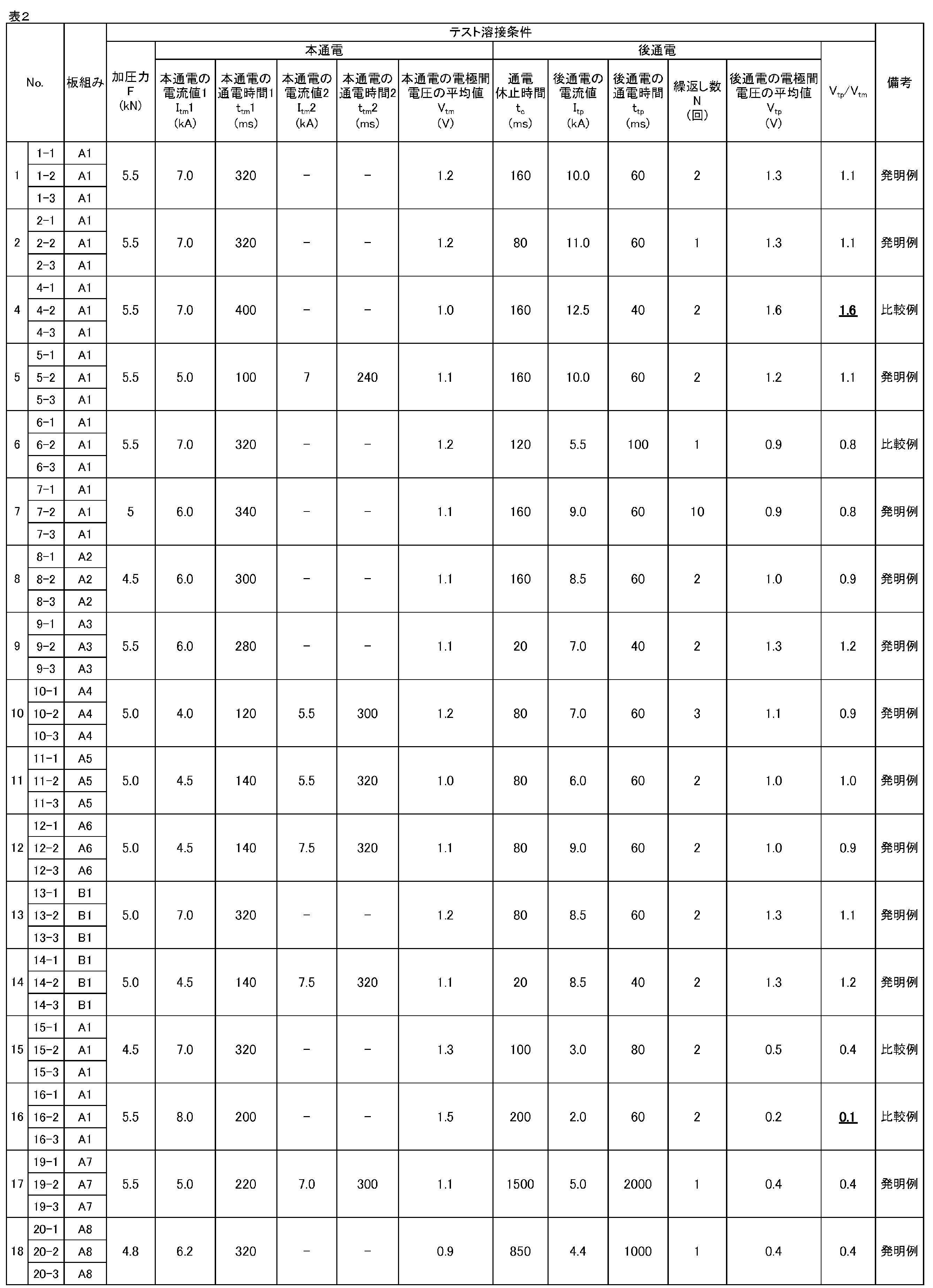
- the “energization time of post-energization” in the test welding conditions in Table 2 is the energization time of post-energization per cycle.
- the energization suspension time, the post-energization current value, and the post-energization energization time under the test welding conditions in Table 2 were the same in all times of the post-energization. Further, for those described as “constant current control” in the “main energization control method” and “post-energization control method” in the main welding conditions in Table 3, the constant current control under the same conditions as the test welding was performed. Was. In addition, when the main welding was performed in a state where there was a hit point, the hit point was cut off from the L-shaped tensile test piece, and a tensile test described later was performed.
- ⁇ B No hitting points or LTS of 2.0 kN or more with hitting interval L ⁇ 10 mm, LTS of less than 2.0 kN with hitting interval L ⁇ 10 mm, and no scattering.
- ⁇ F There is no hitting point or LTS is less than 2.0kN or hitting interval L ⁇ 10mm.
- the evaluation was either A or B.
- all the evaluations were A under the conditions in which the energization suspension after the main energization and the post-energization were repeated two or more times.
- all the comparative examples which did not satisfy the appropriate conditions were evaluated as F, and could not obtain sufficient joint strength.
Landscapes
- Engineering & Computer Science (AREA)
- Mechanical Engineering (AREA)
- Quality & Reliability (AREA)
- Resistance Welding (AREA)
- Manufacturing Of Electrical Connectors (AREA)
- Lining Or Joining Of Plastics Or The Like (AREA)
Abstract
Description
この溶接法は、重ね合わせた2枚以上の鋼板を挟んでその上下から一対の電極で加圧しつつ、上下電極間に高電流の溶接電流を短時間通電して接合する方法であり、高電流の溶接電流を流すことで発生する抵抗発熱を利用して、点状の溶接部が得られる。この点状の溶接部はナゲットと呼ばれ、重ね合わせた鋼板に電流を流した際に鋼板の接触箇所で両鋼板が溶融し、凝固した部分である。このナゲットにより、鋼板同士が点状に接合される。
例えば、特許文献1には、高張力鋼板への通電電流を漸変的に上昇させることによりナゲット生成を行なう第1ステップと、上記第1ステップの後に電流を下降させる第2ステップと、上記第2ステップ後に電流を上昇させて本溶接すると共に、漸変的に通電電流を下降させる第3ステップとを備えた工程によりスポット溶接を行なうことで、通電初期のなじみ不良に起因する散りを抑制しようとする高張力鋼板のスポット溶接方法が記載されている。
また、本発明は、上記の抵抗スポット溶接方法により、重ね合わせた複数枚の金属板を接合する、溶接部材の製造方法を提供することを目的とする。
前述したように、分流や板隙といった外乱が存在すると、外乱が無い場合と同じ条件で定電流制御による溶接を行ったとしても、得られるナゲット径は変動する。
この点、事前にテスト溶接を行い、本溶接を、当該テスト溶接で得られた累積発熱量を目標値に設定して通電量(電流および電極間電圧)を制御するいわゆる適応制御溶接を行うことで、外乱の影響を加味した適切な通電を行うことが可能となり、その結果、外乱によらず一定のナゲット径を得ることが可能となる。
しかし、外乱の存在下で適応制御による後通電を行うと、外乱により溶接部の電流密度分布、ひいては発熱形態が変化し、所定の熱処理効果が得られない場合がある。例えば、分流の影響が顕著な状態で適応制御による後通電を行うと、分流の影響で電極との接触端近傍での電流密度が過剰に増加して、表散りが生じ、所定の熱処理効果が得られない場合がある。また、適応制御による電流の制御が追い付かずに、目標とする発熱量が得られず、そのため、所定の熱処理効果が得られない場合もある。
外乱がある場合には、外乱が無い場合と比較して、より厳密に後通電の条件を設定することが必要となる。そこで、適応制御溶接における電流値を決定するための重要な指針となるパラメータのひとつである電極間電圧に着目して検討を進めた。
その結果、
・テスト溶接の本通電の電極間電圧の平均値に対する後通電の電極間電圧の平均値の比(以下、テスト溶接時の本通電と後通電の電圧比ともいう)を適正化したうえで、テスト溶接の後通電を定電流制御により行い、かつ、その適正な条件下で行う当該テスト溶接の後通電における単位体積当たりの瞬時発熱量の時間変化曲線および単位体積当たりの累積発熱量を記憶させ、
・本溶接の後通電では、上記のようにして記憶させたテスト溶接の後通電における単位体積当たりの瞬時発熱量の時間変化曲線および単位体積当たりの累積発熱量を目標値として、適応制御を行う、
ことによって、外乱がある状態で後通電を適応制御により行っても、十分な熱処理効果が得られ、初期した目的を達成できる、との知見を得た。
本発明は、上記の知見に基づき、さらに検討を加えて完成されたものである。
1.複数枚の金属板を重ね合わせた被溶接材を、一対の電極によって挟み、加圧しながら通電して接合する抵抗スポット溶接方法であって、
本溶接と、該本溶接に先立つテスト溶接とを行うものとし、
(a)上記テスト溶接では、ナゲットを形成するための本通電および後熱処理のための後通電を行い、
前記テスト溶接の本通電では、
定電流制御により通電して、適正なナゲットを形成する場合の電極間の電気特性から算出される、単位体積当たりの瞬時発熱量の時間変化曲線および単位体積当たりの累積発熱量をそれぞれ記憶させ、
前記テスト溶接の後通電では、
前記テスト溶接における本通電の電極間電圧の平均値をVtm、前記テスト溶接における後通電の電極間電圧の平均値をVtpとしたとき、
0.2≦Vtp/Vtm≦1.5
の関係を満足する条件で、定電流制御により通電し、
また、その際、電極間の電気特性から算出される、単位体積当たりの瞬時発熱量の時間変化曲線および単位体積当たりの累積発熱量を記憶させ、
(b)ついで、前記本溶接では、ナゲットを形成するための本通電および後熱処理のための後通電を行い、
前記本溶接の本通電および後通電では、それぞれ前記テスト溶接の本通電および後通電における単位体積当たりの瞬時発熱量の時間変化曲線および単位体積当たりの累積発熱量を目標値に設定し、該目標値に従って通電量を制御する適応制御溶接を行う、
抵抗スポット溶接方法。
また、本発明によれば、自動車の製造などの実作業において次々と流れてくる被処理材を連続的に溶接する(溶接位置や被処理材ごとに外乱の状態が変動する)場合であっても、外乱の状態の変動に有効に対応して所望のナゲット径を安定的に確保することが可能となり、その結果、作業効率や歩留まりの向上という点でも極めて有利となる。
本発明の一実施形態は、複数枚の金属板を重ね合わせた被溶接材を、一対の電極によって挟み、加圧しながら通電して接合する抵抗スポット溶接方法であって、
本溶接と、該本溶接に先立つテスト溶接とを行うものとし、
(a)上記テスト溶接では、ナゲットを形成するための本通電および後熱処理のための後通電を行い、
前記テスト溶接の本通電では、
定電流制御により通電して、適正なナゲットを形成する場合の電極間の電気特性から算出される、単位体積当たりの瞬時発熱量の時間変化曲線および単位体積当たりの累積発熱量をそれぞれ記憶させ、
前記テスト溶接の後通電では、
前記テスト溶接における本通電の電極間電圧の平均値をVtm、前記テスト溶接における後通電の電極間電圧の平均値をVtpとしたとき、
0.2≦Vtp/Vtm≦1.5
の関係を満足する条件で、定電流制御により通電し、
また、その際、電極間の電気特性から算出される、単位体積当たりの瞬時発熱量の時間変化曲線および単位体積当たりの累積発熱量を記憶させ、
(b)ついで、前記本溶接では、ナゲットを形成するための本通電および後熱処理のための後通電を行い、
前記本溶接の本通電および後通電では、それぞれ前記テスト溶接の本通電および後通電における単位体積当たりの瞬時発熱量の時間変化曲線および単位体積当たりの累積発熱量を目標値に設定し、該目標値に従って通電量を制御する適応制御溶接を行う、というものである。
テスト溶接では、ナゲットを形成するための本通電および後熱処理のための後通電をそれぞれ定電流制御により行う。
そして、テスト溶接の本通電では、定電流制御により通電して適正なナゲットを形成する場合の電極間の電気特性から算出される、単位体積当たりの瞬時発熱量の時間変化曲線および単位体積当たりの累積発熱量を記憶させる。
なお、テスト溶接は、外乱のない状態で行っても、分流や板隙などの外乱がある状態(外乱を想定した状態)で行ってもよい。
なお、定電流制御には、通電中にわたり電流値を一定とする通電パターンはもとより、上記した図1(a)~(f)に示すような通電パターン、さらに、これらを組み合わせた通電パターンも含むものとする。テスト溶接の後通電で行う定電流制御についても同様である。
0.2≦Vtp/Vtm≦1.5
の関係を満足する条件で、定電流制御により通電し、その際、電極間の電気特性から算出される、単位体積当たりの瞬時発熱量の時間変化曲線および単位体積当たりの累積発熱量を記憶させることが重要となる。
すなわち、前述したとおり、後述の本溶接において、外乱の存在下で適応制御による後通電を行うと、外乱により溶接部の電流密度分布、ひいては発熱形態が変化し、所定の熱処理効果が得られない場合がある。
この点、テスト溶接の後通電を、上記の関係を満足する条件で行えば、本溶接の適応制御による後通電において、溶接部の電流密度および発熱量が過大となるのを防止できる。例えば、本溶接において、分流が顕著な状態で適応制御による後通電を行ったとしても、電極表面近傍での過剰発熱を抑止することができ、表散りの発生を防止できる。そのため、当該テスト溶接の後通電における単位体積当たりの瞬時発熱量の時間変化曲線および単位体積当たりの累積発熱量を記憶させ、これらを目標値として、後述する本溶接の後通電を適応制御により行えば、外乱が存在する場合にも、当該本溶接の後通電における発熱量を、所定の熱処理効果が得られる範囲に制御することが可能となる。
そのため、テスト溶接の後通電では、
0.2≦Vtp/Vtm≦1.5
の関係を満足させることが重要となる。
0.4≦Vtp/Vtm≦1.4
の関係を満たすことがより好適である。
なお、本通電および後通電のいずれにおいても、通電中に冷却時間が設けられている場合は、冷却時間を除いた通電中における電極間電圧の時間平均を用いることとする。
すなわち、本通電および後通電における電極間電圧の時間積分値をそれぞれ、(通電休止時間を除いた)本通電および後通電における合計の通電時間で除した値を、本通電および後通電における電極間電圧の平均値とする。
加えて、テスト溶接の本通電における合計の通電時間(通電休止時間を除く)は、60~1000msとすることが好適である。
加えて、テスト溶接の1回あたりの後通電における通電時間は、20~3000msとすることが好適である。より好ましくは60~3000msである。
上記のテスト溶接後、本溶接を行う。
本溶接の本通電では、上記テスト溶接の本通電で記憶させた単位体積当たりの瞬時発熱量の時間変化曲線および単位体積当たりの累積発熱量を目標値に設定し、該目標値に従って通電量を制御する適応制御溶接を行う。
この本溶接の本通電における適応制御溶接では、例えば、上記のテスト溶接の本通電で目標値に設定した単位体積当たりの瞬時発熱量の時間変化曲線および累積発熱量を基準として溶接を行い、単位体積当たりの瞬時発熱量の時間変化量が基準である時間変化曲線に沿っている場合には、そのまま溶接を行って溶接を終了する。ただし、単位体積当たりの瞬時発熱量の時間変化量が基準である時間変化曲線から外れた場合には、その外れ量を残りの本溶接の本通電における通電時間内で補償すべく、本溶接の本通電での単位体積当たりの累積発熱量が、目標値として設定した単位体積当たりの累積発熱量と一致するように通電量を制御する。
被溶接材の合計厚みをt、被溶接材の電気抵抗率をr、電極間電圧をV、溶接電流をIとし、電極と被溶接材が接触する面積をSとする。この場合、溶接電流は横断面積がSで、厚みtの柱状部分を通過して抵抗発熱を発生させる。この柱状部分における単位体積・単位時間当たりの発熱量qは次式(1)で求められる。
q=(V・I)/(S・t) --- (1)
また、この柱状部分の電気抵抗Rは、次式(2)で求められる。
R=(r・t)/S --- (2)
(2)式をSについて解いてこれを(1)式に代入すると、発熱量qは次式(3)
q=(V・I・R)/(r・t2)
=(V2)/(r・t2) --- (3)
となる。
以上、特許文献5記載の方法によって、累積発熱量Qを算出する場合について説明したが、その他の算出式を用いても良いのは言うまでもない。
前述したように、本発明の一実施形態では、テスト溶接の後通電を、より適切な条件、具体的には、0.2≦Vtp/Vtm≦1.5の関係を満足する条件で、定電流制御により行う。
そのため、当該テスト溶接の後通電の単位体積当たりの瞬時発熱量の時間変化曲線および単位体積当たりの累積発熱量を記憶させ、これらを目標値として、本溶接の後通電を適応制御により行えば、外乱が存在する場合であっても、後熱処理に適した発熱量が得られ、その結果、所定の熱処理効果が得られるのである。
さらに、図2(a)および(b)に示すように、テスト溶接における本通電後の通電休止および後通電を2回以上繰り返してもよい。これにより、より有利に所定の熱処理効果が得られる。すなわち、仮に1回目の後通電で過剰発熱となり再溶融が生じたとしても、2回目の後通電で熱処理を行い、継手強度を向上させる効果が得られる。繰り返し回数の上限は特に限定されるものではないが、10回程度である。また、回ごとに、通電時間や通電休止時間、電流値をそれぞれ違う値に設定してもよい。
なお、本通電後の通電休止および後通電を2回以上繰り返す場合、テスト溶接の後通電の電流値Itpは、当該後通電における電流の時間積分値を、(通電休止時間を除いた)後通電における合計の通電時間で除した値とする。
テスト溶接の通電パターンを図2に示す。図2(a)は本通電を1段通電とした場合、図2(b)は本通電を2段通電とした場合である。
ここで、テスト溶接は、図3(a)、図4(a)に示すように、外乱の無い状態で行い、本溶接は、テスト溶接と同様の外乱の無い状態、および、図3(b)、図4(b)に示すように、外乱の存在する状態で行った。
図3(a)は2枚重ねで既打点が無い状態、図3(b)は2枚重ねで既打点がある状態であり、既打点と溶接点との打点間隔L(中心間距離)は種々変化させた。
また、図4(a)は3枚重ねで既打点が無い状態、図4(b)は3枚重ねで既打点がある状態である。
なお、表2のテスト溶接条件における「後通電の通電時間」は1回あたりの後通電の通電時間である。また、表2のテスト溶接条件における通電休止時間、後通電の電流値および後通電の通電時間は、後通電の全ての回で同じとした。
さらに、表3の本溶接条件における「本通電の制御方式」および「後通電の制御方式」で「定電流制御」と記載されているものについては、テスト溶接と同じ条件の定電流制御を行った。
なお、既打点がある状態で本溶接を行った場合には、L字引張試験片から既打点部分を切除したうえで、後述する引張試験を行った。
得られたL字引張試験片を用いて、引張速度(長手方向):10mm/minの条件で引張試験を行い、継手強度(LTS:L字引張強さ)を測定した。そして、溶接時の散り有無および継手強度から、以下の3段階で評価した。
・A: 打点間隔LによらずLTSが2.0kN以上、かつすべて散り無し。
・B: 既打点無しまたは打点間隔L≧10mmでLTSが2.0kN以上、打点間隔L<10mmでLTSが2.0kN未満、かつすべて散り無し。
・F: 既打点無しまたは打点間隔L≧10mmでLTSが2.0kN未満、または散りあり。


これに対し、適正条件を満たさない比較例はいずれも、評価はFであり、十分な継手強度を得ることができなかった。
Claims (5)
- 複数枚の金属板を重ね合わせた被溶接材を、一対の電極によって挟み、加圧しながら通電して接合する抵抗スポット溶接方法であって、
本溶接と、該本溶接に先立つテスト溶接とを行うものとし、
(a)上記テスト溶接では、ナゲットを形成するための本通電および後熱処理のための後通電を行い、
前記テスト溶接の本通電では、
定電流制御により通電して、適正なナゲットを形成する場合の電極間の電気特性から算出される、単位体積当たりの瞬時発熱量の時間変化曲線および単位体積当たりの累積発熱量をそれぞれ記憶させ、
前記テスト溶接の後通電では、
前記テスト溶接における本通電の電極間電圧の平均値をVtm、前記テスト溶接における後通電の電極間電圧の平均値をVtpとしたとき、
0.2≦Vtp/Vtm≦1.5
の関係を満足する条件で、定電流制御により通電し、
また、その際、電極間の電気特性から算出される、単位体積当たりの瞬時発熱量の時間変化曲線および単位体積当たりの累積発熱量を記憶させ、
(b)ついで、前記本溶接では、ナゲットを形成するための本通電および後熱処理のための後通電を行い、
前記本溶接の本通電および後通電では、それぞれ前記テスト溶接の本通電および後通電における単位体積当たりの瞬時発熱量の時間変化曲線および単位体積当たりの累積発熱量を目標値に設定し、該目標値に従って通電量を制御する適応制御溶接を行う、
抵抗スポット溶接方法。 - 前記本溶接の本通電における適応制御溶接において、単位体積当たりの瞬時発熱量の時間変化量が、前記目標値に設定した単位体積当たりの瞬時発熱量の時間変化曲線から外れた場合には、その外れ量を残りの前記本溶接の本通電における通電時間内で補償すべく、前記本溶接の本通電での単位体積当たりの累積発熱量が前記目標値に設定した単位体積当たりの累積発熱量と一致するように通電量を制御する、請求項1に記載の抵抗スポット溶接方法。
- 前記本溶接の後通電における適応制御溶接において、単位体積当たりの瞬時発熱量の時間変化量が、前記目標値に設定した単位体積当たりの瞬時発熱量の時間変化曲線から外れた場合には、その外れ量を残りの前記本溶接の後通電における通電時間内で補償すべく、前記本溶接の後通電での単位体積当たりの累積発熱量が前記目標値に設定した単位体積当たりの累積発熱量と一致するように通電量を制御する、請求項1または2に記載の抵抗スポット溶接方法。
- 前記テスト溶接の本通電と後通電の間に、通電休止時間を設定し、かつ、前記テスト溶接の本通電後の通電休止および後通電を2回以上繰り返す、請求項1~3のいずれかに記載の抵抗スポット溶接方法。
- 請求項1~4のいずれかに記載の抵抗スポット溶接方法により、重ね合わせた複数枚の金属板を接合する、溶接部材の製造方法。
Priority Applications (6)
| Application Number | Priority Date | Filing Date | Title |
|---|---|---|---|
| CN201980039788.8A CN112368101B (zh) | 2018-06-29 | 2019-06-17 | 电阻点焊方法和焊接构件的制造方法 |
| JP2019553149A JP6658993B1 (ja) | 2018-06-29 | 2019-06-17 | 抵抗スポット溶接方法および溶接部材の製造方法 |
| MX2020013758A MX2020013758A (es) | 2018-06-29 | 2019-06-17 | Metodo de soldadura por puntos de resistencia y metodo de produccion de miembro de soldadura. |
| US16/973,766 US11904404B2 (en) | 2018-06-29 | 2019-06-17 | Resistance spot welding method and weld member production method |
| EP19826067.1A EP3815834B1 (en) | 2018-06-29 | 2019-06-17 | Resistance spot welding method and method for manufacturing welded member |
| KR1020217002036A KR102415945B1 (ko) | 2018-06-29 | 2019-06-17 | 저항 스폿 용접 방법 및 용접 부재의 제조 방법 |
Applications Claiming Priority (2)
| Application Number | Priority Date | Filing Date | Title |
|---|---|---|---|
| JP2018125392 | 2018-06-29 | ||
| JP2018-125392 | 2018-06-29 |
Publications (1)
| Publication Number | Publication Date |
|---|---|
| WO2020004116A1 true WO2020004116A1 (ja) | 2020-01-02 |
Family
ID=68986510
Family Applications (1)
| Application Number | Title | Priority Date | Filing Date |
|---|---|---|---|
| PCT/JP2019/023966 Ceased WO2020004116A1 (ja) | 2018-06-29 | 2019-06-17 | 抵抗スポット溶接方法および溶接部材の製造方法 |
Country Status (7)
| Country | Link |
|---|---|
| US (1) | US11904404B2 (ja) |
| EP (1) | EP3815834B1 (ja) |
| JP (1) | JP6658993B1 (ja) |
| KR (1) | KR102415945B1 (ja) |
| CN (1) | CN112368101B (ja) |
| MX (1) | MX2020013758A (ja) |
| WO (1) | WO2020004116A1 (ja) |
Cited By (1)
| Publication number | Priority date | Publication date | Assignee | Title |
|---|---|---|---|---|
| WO2025159214A1 (ja) * | 2024-03-14 | 2025-07-31 | 日本製鉄株式会社 | スポット溶接継手の製造方法 |
Citations (10)
| Publication number | Priority date | Publication date | Assignee | Title |
|---|---|---|---|---|
| JPH09216071A (ja) | 1996-02-07 | 1997-08-19 | Matsushita Electric Ind Co Ltd | 抵抗溶接機の制御装置 |
| JPH1094883A (ja) | 1996-09-24 | 1998-04-14 | Matsushita Electric Ind Co Ltd | 抵抗溶接機の溶接条件制御方法 |
| JPH1133743A (ja) | 1997-07-14 | 1999-02-09 | Na Detsukusu:Kk | 単位体積当たりの累積発熱量を指標とする抵抗溶接システム |
| JP2003236674A (ja) | 2002-02-15 | 2003-08-26 | Mazda Motor Corp | 高張力鋼板のスポット溶接方法およびその装置 |
| JP2006043731A (ja) | 2004-08-04 | 2006-02-16 | Daihatsu Motor Co Ltd | スポット溶接の通電制御方法 |
| JP2010221284A (ja) * | 2009-03-25 | 2010-10-07 | Daihen Corp | 抵抗溶接制御方法 |
| WO2014136507A1 (ja) * | 2013-03-08 | 2014-09-12 | Jfeスチール株式会社 | 抵抗スポット溶接方法 |
| WO2016147551A1 (ja) * | 2015-03-16 | 2016-09-22 | Jfeスチール株式会社 | 抵抗スポット溶接方法および抵抗スポット溶接継手の製造方法 |
| WO2016174842A1 (ja) * | 2015-04-27 | 2016-11-03 | Jfeスチール株式会社 | 抵抗スポット溶接方法 |
| WO2017212916A1 (ja) * | 2016-06-09 | 2017-12-14 | Jfeスチール株式会社 | 抵抗スポット溶接方法 |
Family Cites Families (13)
| Publication number | Priority date | Publication date | Assignee | Title |
|---|---|---|---|---|
| US20100065533A1 (en) * | 2008-09-18 | 2010-03-18 | Square D Company | Adaptive Resistance Weld Control |
| US8357871B2 (en) | 2009-05-07 | 2013-01-22 | Innovative Weld Solutions Ltd. | Welding assembly and method |
| JP5052586B2 (ja) * | 2009-11-18 | 2012-10-17 | 株式会社豊田中央研究所 | 抵抗溶接方法、抵抗溶接部材、抵抗溶接機とその制御装置、抵抗溶接機の制御方法とその制御プログラム、抵抗溶接の評価方法とその評価プログラムおよび抵抗溶接の溶融開始時の検出方法 |
| US10391582B2 (en) | 2011-07-21 | 2019-08-27 | Ford Global Technologies, Llc | System and method of welding a workpiece |
| US8895887B2 (en) | 2011-08-05 | 2014-11-25 | General Electric Company | Resistance weld repairing of casing flange holes |
| JP5333560B2 (ja) | 2011-10-18 | 2013-11-06 | Jfeスチール株式会社 | 高張力鋼板の抵抗スポット溶接方法及び抵抗スポット溶接継手 |
| KR101584495B1 (ko) * | 2013-03-29 | 2016-01-13 | 제이에프이 스틸 가부시키가이샤 | 저항 스폿 용접 시스템 |
| US20160082543A1 (en) * | 2013-06-05 | 2016-03-24 | Nippon Steel & Sumitomo Metal Corporation | Spot-welded joint and spot welding method |
| EP3053693B1 (en) * | 2013-10-04 | 2018-02-21 | JFE Steel Corporation | Resistance spot welding method |
| MX349400B (es) * | 2013-12-27 | 2017-07-27 | Jfe Steel Corp | Método de soldadura por puntos de resistencia. |
| WO2015190082A1 (ja) | 2014-06-12 | 2015-12-17 | Jfeスチール株式会社 | 抵抗スポット溶接装置および抵抗スポット溶接方法 |
| US10272515B2 (en) * | 2015-09-15 | 2019-04-30 | GM Global Technology Operations LLC | Power pulse method for controlling resistance weld nugget growth and properties during steel spot welding |
| US10036731B2 (en) | 2016-03-31 | 2018-07-31 | Honda Motor Co., Ltd. | Weld testing system and method for a welding assembly |
-
2019
- 2019-06-17 US US16/973,766 patent/US11904404B2/en active Active
- 2019-06-17 MX MX2020013758A patent/MX2020013758A/es unknown
- 2019-06-17 JP JP2019553149A patent/JP6658993B1/ja active Active
- 2019-06-17 KR KR1020217002036A patent/KR102415945B1/ko active Active
- 2019-06-17 EP EP19826067.1A patent/EP3815834B1/en active Active
- 2019-06-17 WO PCT/JP2019/023966 patent/WO2020004116A1/ja not_active Ceased
- 2019-06-17 CN CN201980039788.8A patent/CN112368101B/zh active Active
Patent Citations (10)
| Publication number | Priority date | Publication date | Assignee | Title |
|---|---|---|---|---|
| JPH09216071A (ja) | 1996-02-07 | 1997-08-19 | Matsushita Electric Ind Co Ltd | 抵抗溶接機の制御装置 |
| JPH1094883A (ja) | 1996-09-24 | 1998-04-14 | Matsushita Electric Ind Co Ltd | 抵抗溶接機の溶接条件制御方法 |
| JPH1133743A (ja) | 1997-07-14 | 1999-02-09 | Na Detsukusu:Kk | 単位体積当たりの累積発熱量を指標とする抵抗溶接システム |
| JP2003236674A (ja) | 2002-02-15 | 2003-08-26 | Mazda Motor Corp | 高張力鋼板のスポット溶接方法およびその装置 |
| JP2006043731A (ja) | 2004-08-04 | 2006-02-16 | Daihatsu Motor Co Ltd | スポット溶接の通電制御方法 |
| JP2010221284A (ja) * | 2009-03-25 | 2010-10-07 | Daihen Corp | 抵抗溶接制御方法 |
| WO2014136507A1 (ja) * | 2013-03-08 | 2014-09-12 | Jfeスチール株式会社 | 抵抗スポット溶接方法 |
| WO2016147551A1 (ja) * | 2015-03-16 | 2016-09-22 | Jfeスチール株式会社 | 抵抗スポット溶接方法および抵抗スポット溶接継手の製造方法 |
| WO2016174842A1 (ja) * | 2015-04-27 | 2016-11-03 | Jfeスチール株式会社 | 抵抗スポット溶接方法 |
| WO2017212916A1 (ja) * | 2016-06-09 | 2017-12-14 | Jfeスチール株式会社 | 抵抗スポット溶接方法 |
Non-Patent Citations (1)
| Title |
|---|
| See also references of EP3815834A4 |
Cited By (3)
| Publication number | Priority date | Publication date | Assignee | Title |
|---|---|---|---|---|
| WO2025159214A1 (ja) * | 2024-03-14 | 2025-07-31 | 日本製鉄株式会社 | スポット溶接継手の製造方法 |
| JPWO2025159214A1 (ja) * | 2024-03-14 | 2025-07-31 | ||
| JP7842374B2 (ja) | 2024-03-14 | 2026-04-08 | 日本製鉄株式会社 | スポット溶接継手の製造方法 |
Also Published As
| Publication number | Publication date |
|---|---|
| JPWO2020004116A1 (ja) | 2020-07-02 |
| JP6658993B1 (ja) | 2020-03-04 |
| EP3815834A1 (en) | 2021-05-05 |
| CN112368101B (zh) | 2022-03-11 |
| US20210252629A1 (en) | 2021-08-19 |
| EP3815834A4 (en) | 2021-09-22 |
| KR20210021569A (ko) | 2021-02-26 |
| US11904404B2 (en) | 2024-02-20 |
| CN112368101A (zh) | 2021-02-12 |
| MX2020013758A (es) | 2021-03-02 |
| KR102415945B1 (ko) | 2022-06-30 |
| EP3815834B1 (en) | 2024-09-18 |
Similar Documents
| Publication | Publication Date | Title |
|---|---|---|
| KR101974298B1 (ko) | 저항 스폿 용접 방법 | |
| JP5999293B1 (ja) | 抵抗スポット溶接方法および抵抗スポット溶接継手の製造方法 | |
| JP6652228B1 (ja) | 抵抗スポット溶接方法および溶接部材の製造方法 | |
| JP6471841B1 (ja) | 抵抗スポット溶接方法および溶接部材の製造方法 | |
| JP6241580B1 (ja) | 抵抗スポット溶接方法 | |
| JP6590121B1 (ja) | 抵抗スポット溶接方法および溶接部材の製造方法 | |
| JPWO2016088319A1 (ja) | 抵抗スポット溶接方法 | |
| KR20160050085A (ko) | 저항 스폿 용접 방법 | |
| WO2020095847A1 (ja) | 抵抗スポット溶接方法および溶接部材の製造方法 | |
| JP6658992B1 (ja) | 抵抗スポット溶接方法および溶接部材の製造方法 | |
| JP6969649B2 (ja) | 抵抗スポット溶接方法および溶接部材の製造方法 | |
| JP6658993B1 (ja) | 抵抗スポット溶接方法および溶接部材の製造方法 | |
| JP6856181B1 (ja) | 抵抗スポット溶接方法および溶接部材の製造方法 |
Legal Events
| Date | Code | Title | Description |
|---|---|---|---|
| ENP | Entry into the national phase |
Ref document number: 2019553149 Country of ref document: JP Kind code of ref document: A |
|
| 121 | Ep: the epo has been informed by wipo that ep was designated in this application |
Ref document number: 19826067 Country of ref document: EP Kind code of ref document: A1 |
|
| NENP | Non-entry into the national phase |
Ref country code: DE |
|
| ENP | Entry into the national phase |
Ref document number: 20217002036 Country of ref document: KR Kind code of ref document: A |
|
| WWE | Wipo information: entry into national phase |
Ref document number: 2019826067 Country of ref document: EP |