WO2020004346A1 - 蓄熱材ユニット、およびこの蓄熱材ユニットを搭載した自動販売機 - Google Patents
蓄熱材ユニット、およびこの蓄熱材ユニットを搭載した自動販売機 Download PDFInfo
- Publication number
- WO2020004346A1 WO2020004346A1 PCT/JP2019/025004 JP2019025004W WO2020004346A1 WO 2020004346 A1 WO2020004346 A1 WO 2020004346A1 JP 2019025004 W JP2019025004 W JP 2019025004W WO 2020004346 A1 WO2020004346 A1 WO 2020004346A1
- Authority
- WO
- WIPO (PCT)
- Prior art keywords
- product
- heat storage
- storage material
- storage
- heat
- Prior art date
- Legal status (The legal status is an assumption and is not a legal conclusion. Google has not performed a legal analysis and makes no representation as to the accuracy of the status listed.)
- Ceased
Links
Images


Classifications
-
- F—MECHANICAL ENGINEERING; LIGHTING; HEATING; WEAPONS; BLASTING
- F25—REFRIGERATION OR COOLING; COMBINED HEATING AND REFRIGERATION SYSTEMS; HEAT PUMP SYSTEMS; MANUFACTURE OR STORAGE OF ICE; LIQUEFACTION SOLIDIFICATION OF GASES
- F25D—REFRIGERATORS; COLD ROOMS; ICE-BOXES; COOLING OR FREEZING APPARATUS NOT OTHERWISE PROVIDED FOR
- F25D11/00—Self-contained movable devices, e.g. domestic refrigerators
- F25D11/006—Self-contained movable devices, e.g. domestic refrigerators with cold storage accumulators
-
- F—MECHANICAL ENGINEERING; LIGHTING; HEATING; WEAPONS; BLASTING
- F28—HEAT EXCHANGE IN GENERAL
- F28D—HEAT-EXCHANGE APPARATUS, NOT PROVIDED FOR IN ANOTHER SUBCLASS, IN WHICH THE HEAT-EXCHANGE MEDIA DO NOT COME INTO DIRECT CONTACT
- F28D20/00—Heat storage plants or apparatus in general; Regenerative heat-exchange apparatus not covered by groups F28D17/00 or F28D19/00
- F28D20/02—Heat storage plants or apparatus in general; Regenerative heat-exchange apparatus not covered by groups F28D17/00 or F28D19/00 using latent heat
- F28D20/021—Heat storage plants or apparatus in general; Regenerative heat-exchange apparatus not covered by groups F28D17/00 or F28D19/00 using latent heat the latent heat storage material and the heat-exchanging means being enclosed in one container
-
- F—MECHANICAL ENGINEERING; LIGHTING; HEATING; WEAPONS; BLASTING
- F25—REFRIGERATION OR COOLING; COMBINED HEATING AND REFRIGERATION SYSTEMS; HEAT PUMP SYSTEMS; MANUFACTURE OR STORAGE OF ICE; LIQUEFACTION SOLIDIFICATION OF GASES
- F25D—REFRIGERATORS; COLD ROOMS; ICE-BOXES; COOLING OR FREEZING APPARATUS NOT OTHERWISE PROVIDED FOR
- F25D11/00—Self-contained movable devices, e.g. domestic refrigerators
-
- F—MECHANICAL ENGINEERING; LIGHTING; HEATING; WEAPONS; BLASTING
- F25—REFRIGERATION OR COOLING; COMBINED HEATING AND REFRIGERATION SYSTEMS; HEAT PUMP SYSTEMS; MANUFACTURE OR STORAGE OF ICE; LIQUEFACTION SOLIDIFICATION OF GASES
- F25D—REFRIGERATORS; COLD ROOMS; ICE-BOXES; COOLING OR FREEZING APPARATUS NOT OTHERWISE PROVIDED FOR
- F25D17/00—Arrangements for circulating cooling fluids; Arrangements for circulating gas, e.g. air, within refrigerated spaces
- F25D17/04—Arrangements for circulating cooling fluids; Arrangements for circulating gas, e.g. air, within refrigerated spaces for circulating air, e.g. by convection
- F25D17/06—Arrangements for circulating cooling fluids; Arrangements for circulating gas, e.g. air, within refrigerated spaces for circulating air, e.g. by convection by forced circulation
- F25D17/08—Arrangements for circulating cooling fluids; Arrangements for circulating gas, e.g. air, within refrigerated spaces for circulating air, e.g. by convection by forced circulation using ducts
-
- F—MECHANICAL ENGINEERING; LIGHTING; HEATING; WEAPONS; BLASTING
- F25—REFRIGERATION OR COOLING; COMBINED HEATING AND REFRIGERATION SYSTEMS; HEAT PUMP SYSTEMS; MANUFACTURE OR STORAGE OF ICE; LIQUEFACTION SOLIDIFICATION OF GASES
- F25D—REFRIGERATORS; COLD ROOMS; ICE-BOXES; COOLING OR FREEZING APPARATUS NOT OTHERWISE PROVIDED FOR
- F25D23/00—General constructional features
- F25D23/06—Walls
- F25D23/065—Details
- F25D23/066—Liners
-
- G—PHYSICS
- G07—CHECKING-DEVICES
- G07F—COIN-FREED OR LIKE APPARATUS
- G07F11/00—Coin-freed apparatus for dispensing, or the like, discrete articles
- G07F11/02—Coin-freed apparatus for dispensing, or the like, discrete articles from non-movable magazines
- G07F11/04—Coin-freed apparatus for dispensing, or the like, discrete articles from non-movable magazines in which magazines the articles are stored one vertically above the other
- G07F11/10—Coin-freed apparatus for dispensing, or the like, discrete articles from non-movable magazines in which magazines the articles are stored one vertically above the other two or more magazines having a common delivery chute
-
- G—PHYSICS
- G07—CHECKING-DEVICES
- G07F—COIN-FREED OR LIKE APPARATUS
- G07F11/00—Coin-freed apparatus for dispensing, or the like, discrete articles
- G07F11/02—Coin-freed apparatus for dispensing, or the like, discrete articles from non-movable magazines
- G07F11/04—Coin-freed apparatus for dispensing, or the like, discrete articles from non-movable magazines in which magazines the articles are stored one vertically above the other
- G07F11/16—Delivery means
-
- G—PHYSICS
- G07—CHECKING-DEVICES
- G07F—COIN-FREED OR LIKE APPARATUS
- G07F11/00—Coin-freed apparatus for dispensing, or the like, discrete articles
- G07F11/02—Coin-freed apparatus for dispensing, or the like, discrete articles from non-movable magazines
- G07F11/28—Coin-freed apparatus for dispensing, or the like, discrete articles from non-movable magazines in which the magazines are inclined
- G07F11/32—Coin-freed apparatus for dispensing, or the like, discrete articles from non-movable magazines in which the magazines are inclined two or magazines having a common delivery chute
-
- G—PHYSICS
- G07—CHECKING-DEVICES
- G07F—COIN-FREED OR LIKE APPARATUS
- G07F11/00—Coin-freed apparatus for dispensing, or the like, discrete articles
- G07F11/02—Coin-freed apparatus for dispensing, or the like, discrete articles from non-movable magazines
- G07F11/34—Coin-freed apparatus for dispensing, or the like, discrete articles from non-movable magazines in which the magazines are of zig-zag form
-
- G—PHYSICS
- G07—CHECKING-DEVICES
- G07F—COIN-FREED OR LIKE APPARATUS
- G07F11/00—Coin-freed apparatus for dispensing, or the like, discrete articles
- G07F11/46—Coin-freed apparatus for dispensing, or the like, discrete articles from movable storage containers or supports
-
- G—PHYSICS
- G07—CHECKING-DEVICES
- G07F—COIN-FREED OR LIKE APPARATUS
- G07F11/00—Coin-freed apparatus for dispensing, or the like, discrete articles
- G07F11/46—Coin-freed apparatus for dispensing, or the like, discrete articles from movable storage containers or supports
- G07F11/48—Coin-freed apparatus for dispensing, or the like, discrete articles from movable storage containers or supports the storage containers or supports, e.g. magazine, being pivotally mounted
-
- G—PHYSICS
- G07—CHECKING-DEVICES
- G07F—COIN-FREED OR LIKE APPARATUS
- G07F9/00—Details other than those peculiar to special kinds or types of apparatus
- G07F9/10—Casings or parts thereof, e.g. with means for heating or cooling
-
- G—PHYSICS
- G07—CHECKING-DEVICES
- G07F—COIN-FREED OR LIKE APPARATUS
- G07F9/00—Details other than those peculiar to special kinds or types of apparatus
- G07F9/10—Casings or parts thereof, e.g. with means for heating or cooling
- G07F9/105—Heating or cooling means, for temperature and humidity control, for the conditioning of articles and their storage
-
- F—MECHANICAL ENGINEERING; LIGHTING; HEATING; WEAPONS; BLASTING
- F25—REFRIGERATION OR COOLING; COMBINED HEATING AND REFRIGERATION SYSTEMS; HEAT PUMP SYSTEMS; MANUFACTURE OR STORAGE OF ICE; LIQUEFACTION SOLIDIFICATION OF GASES
- F25D—REFRIGERATORS; COLD ROOMS; ICE-BOXES; COOLING OR FREEZING APPARATUS NOT OTHERWISE PROVIDED FOR
- F25D2317/00—Details or arrangements for circulating cooling fluids; Details or arrangements for circulating gas, e.g. air, within refrigerated spaces, not provided for in other groups of this subclass
- F25D2317/06—Details or arrangements for circulating cooling fluids; Details or arrangements for circulating gas, e.g. air, within refrigerated spaces, not provided for in other groups of this subclass with forced air circulation
- F25D2317/068—Details or arrangements for circulating cooling fluids; Details or arrangements for circulating gas, e.g. air, within refrigerated spaces, not provided for in other groups of this subclass with forced air circulation characterised by the fans
- F25D2317/0681—Details thereof
-
- F—MECHANICAL ENGINEERING; LIGHTING; HEATING; WEAPONS; BLASTING
- F28—HEAT EXCHANGE IN GENERAL
- F28D—HEAT-EXCHANGE APPARATUS, NOT PROVIDED FOR IN ANOTHER SUBCLASS, IN WHICH THE HEAT-EXCHANGE MEDIA DO NOT COME INTO DIRECT CONTACT
- F28D20/00—Heat storage plants or apparatus in general; Regenerative heat-exchange apparatus not covered by groups F28D17/00 or F28D19/00
- F28D2020/0004—Particular heat storage apparatus
- F28D2020/0026—Particular heat storage apparatus the heat storage material being enclosed in mobile containers for transporting thermal energy
Definitions
- the present invention relates to a heat storage material unit provided with a heat storage material that stores heat by being physically or chemically changed, for example, installed inside a product storage in order to suppress power consumption of a vending machine. And a vending machine equipped with the heat storage material unit.
- This type of vending machine is a product storage that defines a product storage passage in which a plurality of products are stored in a row in a front-rear direction in a body storage cabinet of a main body cabinet constructed as an insulated housing.
- a shelf provided with a product storage rack (also referred to as a slant truck) in which a plurality of shelves are vertically arranged is known.
- the product storage shelves arranged in the product storage rack in upper and lower tiers are arranged so as to be inclined at a predetermined gradient so that the rear side as the product outlet is lower than the front side as the product input port.
- a product discharge device that cuts out and stores the products stored in the product storage passage in a sideways posture one by one.
- a product drop passage extending vertically is formed between the rear end of the product storage shelf and the back wall of the main body cabinet.
- An attitude control plate that pivots between a projecting position that protrudes into the article falling path and a retracted position that is pushed open by the falling article and retracts from the article falling path is provided in the article falling path.
- the plate is urged by a coil spring so as to protrude toward the product drop passage, and when the product is pushed open by the falling product and retreats from the product drop passage, the posture of the product is corrected to a sideways posture.
- the falling energy of the product is absorbed to reduce the falling speed.
- a product delivery shooter in which a plurality of ventilation holes are formed in the front surface of the product storage rack inclined downward and the entire surface of the product storage rack, and the product stored in the product storage passage.
- a cooling / heating unit having an internal fan for cooling or heating the product to a temperature suitable for sale.
- the cooling / heating unit includes an evaporator / heater, and the evaporator forms a refrigeration cycle together with a compressor and a condenser arranged in a machine room below the main cabinet.
- a duct member is provided vertically arranged along the back wall of the main body cabinet.
- the cool air or the heated warm air cooled by the cooling / heating unit (these are also collectively referred to as air in the refrigerator) are blown into the product storage via the duct member by the drive of the fan in the refrigerator, and the product is stored in the refrigerator. After descending inside the storage, it circulates through the ventilation hole of the product unloading shooter to return to the fan inside the storage, and in the process of descending inside the product storage, the products stored in the product storage rack are cooled to the appropriate temperature for sale or It is configured to heat.
- the product stored in the product storage rack When the product stored in the product storage rack is cooled or heated to an appropriate temperature for sale, the product becomes available for sale, and when a product selection button provided on an outer door openably and closably mounted on the front opening of the main body cabinet is pressed, the product is pressed.
- the product unloading device provided on the corresponding product storage shelf operates to unload one product stored in the product storage passage.
- the product carried out by the product carry-out device is corrected in posture by the posture control plate in the process of falling down the product fall path, and at the same time, after landing on the product carry-out shooter after the fall speed is reduced, the product carry-out shooter It is configured to be rolled or slid on the upper side and sent out to a product outlet (for example, Patent Document 1).
- the temperature in the product storage is detected by a temperature detection sensor such as a thermostat, and temperature information (detection temperature) of the temperature detection sensor and a first reference temperature (a predetermined temperature) are set in advance.
- a temperature detection sensor such as a thermostat
- temperature information (detection temperature) of the temperature detection sensor and a first reference temperature are set in advance.
- a first reference temperature a predetermined temperature
- the temperature detected by the temperature detection sensor has not reached the reference temperature
- the cooling / heating unit Is driven to cool or heat the product stored in the product storage rack to a suitable temperature for sale, and then the operation is shifted to a cooling operation or a temperature maintaining operation.
- the temperature detected by the temperature detection sensor is compared with a preset second reference temperature (the upper limit temperature in the case of cooling, and the lower limit temperature in the case of heating).
- a preset second reference temperature the upper limit temperature in the case of cooling, and the lower limit temperature in the case of heating.
- the cooling / heating unit that has been stopped when shifting to the cooling operation or the heating operation is driven to cool or heat the product to a temperature suitable for sale. Is repeated.
- the power consumption of the vending machine is increased. Is known to increase.
- a vending machine equipped with a heat storage material that stores energy (heat) by physically or chemically changing the inside of a product storage for example, Patent Document 2.
- a vending machine equipped with a heat storage material inside a product storage box operates while the cooling / heating unit is in operation (especially during the nighttime power hours when the power demand is small). If energy is stored in the heat storage material, even when the cooling / heating unit is stopped, the temperature in the product storage can be maintained at a temperature near a suitable temperature for sale by the heat storage material. This makes it possible to stop the cooling / heating unit during the time when the power demand peaks.
- JP-A-10-283556 (paragraphs 0002 and 0003 and FIG. 5) Japanese Patent No. 2910282
- Patent Literature 2 by installing a heat storage material that stores heat in a late-night power time zone where the power demand is small, the power consumption in a time zone where the power demand is high is installed inside the product storage. It is excellent in that vending machines with reduced volume can be provided.
- a heat storage material is attached to a heat insulating panel defining a product storage.
- the inside of the product storage of the vending machine is filled with product storage racks in order to maximize the internal volume of the product storage and increase the number of stored products, and the space for attaching the heat storage material is provided. The fact is that there is no space. Therefore, as shown in FIG.
- the fact that the heat storage material 102 takes a long time to dissipate heat means that only a part of the surface area of the heat storage material 102 is used for heat radiation when the temperature in the product storage is maintained at a temperature near the appropriate temperature for sale by the heat storage material 102. In addition, there is a problem that the number or capacity of the heat storage material 102 must be increased.
- the present invention has been made in view of the above points, and has as its object to solve the above-mentioned problems, and to mount a heat storage material unit capable of improving the efficiency of solidification and melting of the heat storage material, and to mount the heat storage material unit. It is to provide a vending machine.
- the invention according to claim 1 is characterized in that a heat storage material covered with a jacket material is stored in a metal storage container having high thermal conductivity.
- the storage container is made of aluminum.
- the storage container in the heat storage material unit according to the first aspect, has a thin box shape having one open side, and has a flange around the open side.
- a product storage rack in which products are stored in a product storage cabinet of a main body cabinet constructed as a heat-insulating housing by a heat-insulating panel, and a product delivery shooter inclined forward and downward.
- a vending machine in which cooling / heating means having an internal fan for cooling or heating a product stored in the product storage rack to a temperature suitable for sale is provided in a vertical order, the vending machine is covered with a covering material.
- a heat storage material unit in which a heat storage material is stored in a metal storage container having high thermal conductivity is embedded in an insulation panel so that the storage container is exposed in the product storage.
- a product storage passage for storing a plurality of products in a line in a front-rear direction in a sideways posture is defined in a product storage of a main body cabinet constructed as a heat insulating casing.
- a product storage rack in which a plurality of product storage shelves are vertically arranged, a product discharge shooter inclined forward and downward, and a refrigerator for cooling or heating a product stored in the product storage passage to a temperature suitable for sale.
- Cooling / heating means having a fan are arranged in the order of up and down, and the product storage shelf is inclined so that a rear side serving as a product outlet is lower than a front side serving as a product input port, and is provided near the product outlet.
- a heat storage material covered with a jacket material is formed of a metal having high thermal conductivity.
- the heat storage material unit formed by accommodating the container for, characterized in that arranged above the top of the article storage shelves of the vertical multistage commodity storage rack. According to a sixth aspect of the present invention, in the vending machine according to the fifth aspect, the heat storage material unit is arranged such that one open side of the storage container faces upward.
- the heat storage material unit converts the heat storage material covered with the jacket material into a metal having high thermal conductivity.
- the heat storage material unit is housed in an insulative storage container, and the heat storage material unit is mounted in a vending machine by being embedded in a heat insulating panel so that the storage container is exposed in the product storage, thereby installing the heat storage material unit. Even when the heat storage material unit is buried in the heat insulating panel to reduce the space required for storage, the storage container of the heat storage material unit is also in the surrounding atmosphere (for example, in a product storage when applied to a vending machine).
- heat storage material By exposing the heat storage material to the surface embedded in the heat insulation panel, it is possible to achieve the same effect as exposing the storage container as a heat transfer element in the product storage. An effect that solidification of the heat storage material (heat storage) and thawing (heat dissipation) efficiency can be improved.
- a product storage passage for storing a plurality of products in a side-by-side posture in a line in a front-rear direction in a product storage of a main body cabinet constructed as an insulated housing.
- a product storage rack in which a plurality of product storage shelves are vertically arranged, a product discharge shooter inclined forward and downward, or a product stored in the product storage passage cooled or cooled to a temperature suitable for sale.
- Cooling / heating means having an in-compartment fan for heating are arranged in the order of up and down, and the product storage shelf is inclined such that the rear side as the product outlet is lower than the front side as the product input port and the product is transported.
- thermoforming material covered with a jacket material is conducted.
- the heat storage material unit which is housed in a high metal storage container, is placed above the uppermost product storage shelf of the upper and lower multi-tiered product storage shelves. By placing it in a dead space caused by being arranged at a predetermined slope so that it becomes lower, the dead space can be used effectively, and the heat storage material is mounted without changing the external dimensions of the vending machine There is an effect that a vending machine can be provided.
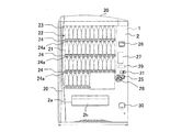
- FIG. 1 is a front view of a vending machine showing an embodiment of the present invention.
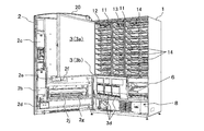
- FIG. 2 is a perspective view of the vending machine of FIG. 1 in a state where an outer door and a heat insulating inner door are opened.
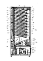
- FIG. 3 is a side sectional view of the vending machine of FIG.
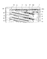
- FIG. 4 is an enlarged side sectional view showing an upper portion of the vending machine of FIG.
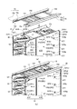
- FIG. 5 is a perspective view of the product storage rack and the guide fitting of FIG. 3 as viewed obliquely from the upper right. 6 is an enlarged view of an upper part of the guide fitting and the product storage rack of FIG.
- FIG. 5 is a perspective view showing a state where the product storage rack is removed from the guide fitting, and (b) is a product storage rack with the guide fitting.
- FIG. 3 is a perspective view of a state in which the device is suspended by being fixed to the device.
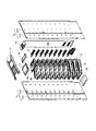
- FIG. 7 is an exploded view of the product storage rack.
- 8A and 8B show the product storage shelves to which the product carry-out device is attached, wherein FIG. 8A is a perspective view as viewed obliquely from the upper right, and FIG. 8B is a rear perspective view of FIG. 9A and 9B show a partition member, wherein FIG. 9A is a top perspective view, and FIG. 9B is a rear perspective view of FIG. 10A and 10B show a posture control plate, in which FIG.
- FIG. 10A is a perspective view as viewed from obliquely upper right on the rear side
- FIG. 10B is an exploded perspective view of FIG. 11A and 11B show the upper fan in the refrigerator
- FIG. 11A is an exploded view of the upper fan and the mounting member
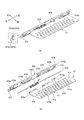
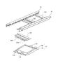
- FIG. 12A and 12B show the front and rear two heat storage material units and the upper fan in the refrigerator together with the guide metal fittings.
- FIG. 12A is a perspective view of the connected state as viewed obliquely from the upper right
- FIG. 12B is an exploded view thereof.
- . 13A and 13B show a heat storage material, wherein FIG. 13A is a side view and FIG. 13B is a plan view.
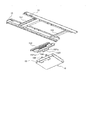
- FIG. 14A and 14B show the heat storage material unit on the rear side together with the holding hardware
- FIG. 14A is an exploded view
- FIG. 14B is an assembly view of the heat storage material unit
- FIG. 14C shows the cooperation between the heat storage material unit and the holding hardware.
- FIG. FIG. 15 is an exploded view showing a relationship between a holding metal member for holding the heat storage material unit on the rear side and a reinforcing metal member laid on the guide metal member, and the reinforcing metal member is disassembled from the guide metal member.
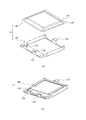
- 16A and 16B show the heat storage material unit on the front side, where FIG. 16A is an exploded view and FIG. 16B is an assembly view of the heat storage material unit.
- FIG. 17 is an exploded view showing the relationship between the heat storage material unit on the front side and the reinforcing metal mounted on the guide metal and exploding the reinforcing metal from the guide metal.
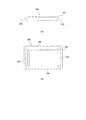
- 18A and 18B show a heat storage material unit according to a different embodiment of the present invention.
- FIG. 18A is a schematic cross-sectional view showing a state where the heat storage material unit is attached to a heat insulating panel
- FIG. 18B is a perspective view of the heat storage material unit.
- FIG. 19 is a schematic cross-sectional view showing a state where a conventional heat storage material is attached to a heat insulating panel.
- FIG. 1 is a front view of a vending machine that sells canned beverages and PET bottled beverages as an example of a vending machine according to an embodiment of the present invention.
- FIG. FIG. 3 is a side sectional view of the vending machine of FIG. 1
- FIG. 4 is an enlarged side sectional view showing an upper part of the vending machine of FIG. 3
- FIG. FIG. 6 is an enlarged perspective view of the product storage rack and the guide fitting as viewed from the upper right side
- FIG. 6 is an enlarged view of the upper part of the guide storage tool and the product storage rack of FIG. 5
- FIG. FIG. 3B is a perspective view of the state
- FIG. 4B is a perspective view of a state in which the product storage rack is suspended from guide fittings.
- “left and right” means left and right when viewed from the front of the vending machine.
- the vending machine has a main body cabinet 1 formed as an insulated housing with an open front surface, and is supported on the front surface of the main body cabinet 1 so as to be openable and closable so as to close the front opening of the main body cabinet 1. And an outer door 2 provided with a product outlet 2a.
- the main body cabinet 1 is provided with an insulating panel made of urethane foam on the inner side of an outer box made of a steel plate, that is, on an upper wall 1a, left and right side walls 1b, a back wall 1c, and a bottom wall 1d (see FIG. 3).
- a space surrounded by the heat insulating panels provided on the upper wall 1a, the left and right side walls 1b, the back wall 1c, and the bottom wall 1d is formed as a product storage, and a lower part of the product storage is formed as a machine room 8. ing.
- the interior of the product storage box surrounded by the heat insulating panels of the main body cabinet 1 is divided into three product storage rooms 12, 13, and 14 in the left and right direction by heat insulating partition plates 11 and 11 (see FIG. 2).
- a product storage rack 4 having product storage shelves 10 arranged in multiple stages in a vertical direction is stored and installed.
- the product storage room 12 is a product cooling store dedicated to cooling, and the product storage rooms 13 and 14 are both a cooling and heating store that can be switched between cooling and heating.
- the open front surface of the product storage in the main body cabinet 1 is closed by a heat-insulating inner door 3 (see FIG. 2) supported by the main body cabinet 1 by a hinge mechanism so as to be openable and closable.
- the heat-insulating inner door 3 is composed of an upper inner door 3a and a lower inner door 3b, and the lower inner door 3b has an outlet flapper 3d which is opened and closed by a product delivered from the product storage.
- 3c (see FIG. 3) is provided.
- the carry-out exit flapper 3d is supported at the upper end thereof to hang down and closes the commodity carry-out section 3c by its own weight to prevent the outflow of cool air or warm air, and is pushed and opened by the goods carried out through the commodity carry-out shooter 6.
- the product is formed so as to be delivered to the product receiving box 2g of the outer door 2.
- the product storage rack 4 includes a pair of left and right rack side plates 41, 41 made of a thin rectangular steel plate.
- the pair of left and right rack side plates 41, 41 are respectively divided into a front rack member 41F and a rear rack member 41R, and are connected to the front rack member 41F and the rear rack member 41R to form one rack side plate 41. Is formed.
- the product storage shelf 10 is erected on the pair of left and right rack side plates 41, 41.
- the product storage shelves 10 are vertically mounted on the left and right rack side plates 41, 41 in such a manner as to be inclined at a predetermined gradient so that the front side serving as the product input port 44 (see FIG. 3) is high and the rear side serving as the product exit port 45 is low.
- a MEC locking member 10A is provided on a pair of left and right rack side plates 41, 41.
- engagement portions 41F1, 41R1 are formed by bending the upper edges outward in a hook shape. 6 (see FIG. 6).
- These engaging portions 41F1 and 41R1 are configured to be able to engage and disengage with a pair of left and right guide fittings 15 laid on the ceiling surface of the product storage.
- the product storage rack 4 is housed in the product storage by engaging the engaging portions 41F1 and 41R1 with the guide fittings 15 and 15, respectively.
- the pair of left and right guide fittings 15, 15 are made of a thick steel plate having a horizontal surface 15a and a vertical surface 15b, and a front part of the horizontal surface 15a and a rear end of the vertical surface 15b are attached to the main body cabinet. 1 and fixed to front and rear reinforcing members RF1 and RF2 (see FIG. 4) extending in the left and right direction on the ceiling surface (the front end is fastened to the reinforcing member RF1 via bolts BT). The rear end is fixed to the reinforcing member RF2) to be laid on the ceiling surface of the product storage.
- rail portions 15 c bent in a hook shape in opposing inward directions, and the rail portions 15 c are engaged with the pair of left and right rack side plates 41, 41. 41F1 and 41R1 are configured to be engaged and disengaged.
- a plurality of reinforcing brackets 151, 152, 153 are horizontally mounted on the pair of left and right guide brackets 15, 15.
- the plurality of reinforcing brackets 151, 152, and 153 have increased mechanical strength by being bent in a manner that the cross section is concave, and are screwed to the horizontal surface 15a of the pair of left and right guide brackets 15, 15.
- a partition member 42 (see FIGS. 4 to 7) is attached to the product storage shelf 10.
- These partition members 42 define a product storage passage 43 (product column) for storing a plurality of products in a line in the front-rear direction in a sideways posture.
- a product unloading device 5 that cuts out products S stored in the product storage passage 43 one by one and discharges the products S is attached.
- an attachment (not shown) for adjusting the distance between the product carrying-out device 5 and the passage surface of the product storage passage 43 is laid on the product storage shelf 10 as necessary.
- the MEC locking member 10A installed above the uppermost product storage passage 43 is for mounting the product unloading device 5 that cuts out the products stored in the uppermost product storage passage 43 one by one.
- An internal upper fan F2 is provided above the rear end of the MEC locking member 10A.
- the upper region of the rear end of the MEC engaging member 10A is a portion that becomes a dead space when the MEC engaging member 10A is arranged with a predetermined inclination so that the rear side is lower than the front side.
- the inside upper fan F2 is provided using the dead space.
- the in-compartment upper fan F2 blows the in-compartment air that has risen through the upper duct member 70b downward, and is bridged between a pair of left and right rack side plates 41,41.
- the MEC locking member 10A and the product storage shelf 10 are arranged at a predetermined inclination so that the rear side is lower than the front side, and the front area of the in-compartment upper fan F2 which becomes a dead space is provided in the front area.
- Two heat storage material units 16 and 17 are arranged in the front-back direction. Although details of these heat storage material units 16 and 17 will be described later, a heat storage material 180 covered with a jacket material is stored in metal storage containers 160 and 170 having high thermal conductivity.
- the rear ends (commodity exits 45) of the commodity storage shelves 10 arranged in the upper and lower tiers in each of the commodity storage racks 4 are located on the same vertical line, and the product exits 45 and the upper duct member 70b are connected to each other.
- the space is formed as a commodity falling passage 46 (see FIG. 3) in which the commodity S falls.
- the product drop passage 46 has a center of rotation at a position close to the rear end of each of the product storage shelves 10 and protrudes into the product drop passage 46.
- a posture control plate 47 that rotates between a retreat position that retreats from the fall passage 46 is provided.
- the attitude control plate 47 is urged by a coil spring 470 (see FIG.
- the attitude control plate 47 is provided so as to span a pair of left and right rack side plates 41, 41.
- a cover member 48 (see FIG. 2) is provided below the pair of left and right rack side plates 41, 41 (front side rack members 41F, 41F).
- the cover member 48 is disposed in a region below the lowermost product storage shelf 10, and even if a hand is inserted from the product outlet 2 a of the outer door 2, the lowermost product storage shelf 10 can be reached. It fulfills the function of preventing it from reaching. Since the cover member 48 is formed in a concave shape in a vertical section, it can be used as a storage place for accessories (for example, an attachment (not shown) mounted on a product storage shelf).
- the lower region of the product drop passage 46 and the product carry-out portion 3c provided in the heat-insulating inner door 3 are connected in an inclined manner to the front lowering position and connected to the plate surface.
- a product carry-out shooter 6 having a plurality of ventilation holes, a cooling / heating unit 7 for cooling or heating the products stored in the product storage rack 4 to store them in a cold or hot state, and a temperature sensor (not shown) are provided.
- the product storage rack 4, the product unloading shooter 6, and the cooling / heating unit 7 are arranged in the product storage in the vertical order.
- the cooling / heating unit 7 is disposed in a space behind the commodity unloading shooter 6, which is arranged to be inclined downward and forward as shown in FIG.
- the cooling / heating unit 7 includes an evaporator 7a, a heater 7b, and a lower fan F1 in the refrigerator.
- the evaporator 7a, the heater 7b, and the lower fan F1 in the refrigerator are combined with the lower fan F1, the heater in the refrigerator from the front side. 7b and the evaporator 7a are juxtaposed in the front-rear direction.
- the rotation speed of the lower fan F1 in the refrigerator can be varied by voltage control and PWM control of the fan drive motor.
- the in-compartment lower fan F1, the heater 7b, and the evaporator 7a are arranged in a wind tunnel that surrounds and protects each, and a wind tunnel 70 for a spacer is provided in connection with the wind tunnel of the heater 7b.
- the respective wind tunnels and wind tunnels 70 in the in-compartment lower fan F1, heater 7b, and evaporator 7a are continuous in a tunnel shape as a whole. Further, a lower duct member 70a is provided so as to be continuous with the wind tunnel of the cooling / heating unit 7 and the wind tunnel 70.
- the lower duct member 70 a is disposed along the back of the product storage (the back wall 1 c of the main body cabinet 1), and is located at an entrance side opening (not shown) facing the outlet of the wind tunnel 70 and in a region below the product falling passage 46. An outlet side opening (not shown) for communication is provided.
- An upper duct member 70b is provided in communication with the outlet side opening of the lower duct member 70a.
- the upper duct member 70b is made of a thin steel plate having a U-shaped cross section extending in the up-down direction, and is installed on a pair of left and right rack side plates 41, 41 along the back wall 1c of the main body cabinet 1.
- the width of the upper duct member 70b in the left-right direction corresponds to the width of the pair of left and right rack side plates 41, 41.
- the U-shaped left and right leg pieces (flanges) are screwed to the rear rack member 41R constituting the pair of left and right rack side plates 41, 41 so as to be bridged between the pair of left and right rack side plates 41, 41.
- a refrigerator condensing unit 9 which forms a refrigeration cycle with the evaporator 7a of the cooling / heating unit 7 is disposed in the machine room 8 below the main body cabinet 1.
- the refrigerator condensing unit 9 includes a compressor 9a, a condenser 9b, an external fan 9c, a solenoid valve, an expansion valve (not shown), and the like.
- the condenser 9b disposed outside the product storage and the interior of the product storage. Is connected to the evaporator 7a via a solenoid valve and an expansion valve via a refrigerant pipe.
- the outer door 2 has a size sufficient to cover the front opening of the main body cabinet 1.
- a display room 22 for displaying a plurality of product samples 21 side by side on the front side of the outer door 2 is provided.
- a product selection button is provided on the front surface of a transparent plate 23 covering the display room 22.
- a product selection button unit 24 having 24a is provided.
- a coin insertion slot 25 In the right end area of the display room 22 on the front side of the outer door 2, a coin insertion slot 25, a bill insertion slot 26, an antenna for electronic settlement 27, a return lever 28, an integrated display 29, a coin return slot 30, and a handle lock device. 31 are provided. As shown in FIG.
- a coin processor 2b a banknote processor 2c, a coin collection box 2d, a control box 2e, a remote control setting device 2f, a product receiving box 2g, and the like are provided on the rear side of the outer door 2. .
- a decorative member 20 is attached to the outer door 2 on the left end side and the head.
- the product selection button 24a is a push button switch for the user to select a purchased product.
- the coin slot 25 is an opening through which a user inserts coins.
- the coin inserted through the coin slot 25 is discriminated by the coin processor 2b for authenticity and denomination, and in the case of a genuine coin, it is stored in a change cylinder corresponding to the denomination (the change cylinder is full). In this case, the coin is stored in the coin collection box 2d.) On the other hand, in the case of a counterfeit coin, the coin is returned to the coin return slot 30.
- the bill insertion slot 26 is an opening for a user to insert a bill.
- the banknotes inserted through the banknote insertion slot 26 are authenticated and denominated in the banknote handling machine 2c, and are accumulated in a storage portion of the banknote handling machine 2c in the case of genuine coins, and are bills in the case of counterfeit coins. It is returned to the insertion slot 26.
- the electronic payment antenna unit 27 exchanges electronic data by holding an IC card or a mobile phone over it, and performs payment through a network.
- the return lever 28 is operated when the user stops purchasing a product after inserting coins or bills. When the return lever 28 is operated, the inserted coins or bills are returned to the coin return slot 30 or the bill insertion. Returned to mouth 26.
- the integrated display 29 is for displaying various information to the user, such as the amount of money inserted, whether the money is on sale, whether there is a change, and the like.
- the handle lock device 31 can lock the outer door 2 to the main body cabinet 1 in a closed state and can release the lock by a key.
- the control box 2e controls the vending machine as a whole, and includes a compressor 9a of the refrigerator condensing unit 9, an electromagnetic valve (not shown) for supplying / stopping refrigerant to the evaporator 7a, and a heater 7b. , A lower fan F1 in the refrigerator, an upper fan F2 in the refrigerator, and a temperature sensor (not shown) in the refrigerator.
- control box 2e based on the temperature information from the internal temperature sensor, according to the program and initial data stored in the memory in advance, the compressor 9a, the solenoid valve, the internal lower fan F1, the internal upper fan F2, After controlling the heater 7b to cool or heat the products stored in the product storage rack 4 to a suitable temperature for sale, the operation shifts to a cooling operation or a heating operation, and maintains the temperature in the product storage at a desired temperature state. It is.
- the product receiving box 2g is formed as a rectangular parallelepiped box-shaped structure having front and rear sides that are open and long in the left-right direction.
- the open front faces the product outlet 2a, and the opened rear face has a plurality of product outlets of the lower inner door 3b. 3c, which receives the goods carried out of the goods storage rack 4.
- the product receiving box 2g has an outlet door 2h (see FIG. 1) for opening and closing a product outlet 2a provided in the outer door 2 for opening and closing the product delivered to the product receiving box 2g.
- An anti-theft plate 2j (see FIG. 2) and the like for suppressing entry of the arm from the exit 2a are integrally provided.
- the product storage shelf 10 includes a front shelf member 10F and a rear shelf member 10R divided in the front-rear direction.
- the front side shelf member 10F is mainly for adjusting the partition member 42.
- the rear side shelf member 10 ⁇ / b> R is mainly used for mounting the product discharging device 5, and the product discharging device 5 is mounted on the back surface.
- Each of the front side shelf member 10F and the rear side shelf member 10R is made of a rectangular flat plate-shaped thin steel plate.
- the front shelf member 10F and the rear shelf member 10R are reinforced by forming flanges 10F1 and 10F1 and flanges 10R1 and 10R1 bent downward from left and right edges of a rectangular plate surface, respectively.
- the left and right flanges 10R1 and 10R1 of the rear shelf member 10R are formed slightly wider in the left and right direction than the left and right flanges 10F1 and 10F1 of the front shelf member 10F.
- the left and right flanges 10F1 and 10F1 of the front shelf member 10F can be sandwiched between the flanges 10R1 and 10R1.
- the front end portion of the front shelf member 10F is bent downward to form a hanging portion 110.
- a guide groove 111 formed as a slit extending in the left-right direction and located near the front of the plate surface on the plate surface of the front shelf member 10F, and a guide groove 111 positioned on the rear side of the guide groove 111, respectively.
- Front and rear two-stage setting grooves 112 formed as slits extending in the front-rear direction and juxtaposed in six rows in the left-right direction, and an attachment (not shown) mounted on the product storage shelf 10 as necessary. 4) are provided with four slit-like mounting grooves 113 for mounting.
- the hanging portion 110, the guide groove 111, and the front and rear two-stage setting grooves 112 are for mounting and adjusting the partition member 42.
- a pin insertion portion 10F11 (see FIG. 8A) is formed by cutting out the front ends of the left and right flanges 10F1 of the front shelf member 10F to form a predetermined gap with the hanging portion 110.
- the pin insertion portion 10F11 is provided so as to straddle the left and right rack side plates 41, 41, and the pin P1 (see also FIGS. 5 and 6) that supports the product storage shelf 10 (front shelf member 10F) is inserted. Things.
- the rear ends of the left and right flanges 10F1 of the front shelf member 10F are cut out so as to be located slightly forward of the rear edge of the plate surface of the front shelf member 10F.
- the rear edge of the plate surface of the front shelf member 10F is formed so as to be located rearward from the rear ends of the left and right flanges 10F1 of the front shelf member 10F, so as to ride on the plate surface of the rear shelf member 10R. It is configured.
- Six fixing portions 124 to 129 are provided on the plate surface of the rear shelf member 10R near the rear of the plate surface, and are located on the right side in the left-right direction near the front of the rear shelf member 10R.
- a pair of left and right openings 130, 130 are provided.
- the six fixing portions 124 to 129 are formed as depressions by being pushed out to the rear side of the plate surface, and screw insertion holes 124a to 129a are formed in the bottom surface of the depressions.
- the six fixing portions 124 to 129 are arranged symmetrically with respect to an intermediate line between the fixing portions 126 and 127. These fixing portions 124 to 129 are for mounting the product carrying device 5.
- the pair of left and right openings 130, 130 is for mounting an attachment (not shown) mounted on the product storage shelf 10 as necessary.
- pin insertion portions 10R11, 10R11 are formed in the front edges of the left and right flanges 10R1, 10R1 of the rear side shelf member 10R by angular cutouts, and circles are formed at the rear ends of the left and right flanges 10R1, 10R1.
- the curled engagement portions 10R12, 10R12 are formed by the arc-shaped notches.
- the pin insertion portions 10R11, 10R11 are disposed so as to straddle the left and right rack side plates 41, 41, and the pins P2 (see also FIGS. 5 and 6) that support the product storage shelf 10 (the rear shelf member 10R) are inserted. Is what is done.
- the curl engaging portions 10R12, 10R12 hold a posture control plate 47, which will be described later with reference to FIG. 9, and have a cylindrical portion formed on a holding member 476 arranged so as to straddle the left and right rack side plates 41, 41. 477.
- the front ends of the left and right flanges 10R1 and 10R1 of the rear shelf member 10R are configured to be located forward of the front end portion of the plate surface of the rear shelf member 10R.
- the front ends of the left and right flanges 10R1 and 10R1 are bent inward to form mounting pieces 10R13 and 10R13 (see FIG. 8B). These mounting pieces 10R13, 10R13 are used for mounting the rear ends of the left and right flanges 10F1 of the front shelf member 10F and connecting to the front shelf member 10F.
- the width in the left-right direction of the left and right flanges 10R1 and 10R1 of the rear shelf member 10R is formed to be slightly wider than the left-right width of the left and right flanges 10F1 and 10F1 of the front shelf member 10F.
- the left and right flanges 10F1 and 10F1 of the front shelf member 10F can be sandwiched between the left and right flanges 10R1 and 10R1 of the side shelf member 10R.
- the rear ends of the left and right flanges 10F1 and 10F1 of the front shelf member 10F are fitted into the front ends of the left and right flanges 10R1 and 10R1 of the rear shelf member 10R, and then the mounting pieces 10R13 and 10R13 of the rear shelf member 10R.
- the front shelf member 10F and the rear shelf member 10R are connected by overlapping the rear ends of the left and right flanges 10F1 of the front shelf member 10F on the front shelf member 10F.
- the rear edge of the plate surface of the front shelf member 10F rides on the plate surface of the rear shelf member 10R, and the product that rolls or slides on the plate surface of the front shelf member 10F is the rear shelf member. It is configured not to collide with the front end portion of 10R.
- the front shelf member 10F and the rear shelf member 10R are attached to a pair of left and right rack side plates 41, 41 as shown in FIGS. That is, after a holding member 476 for holding the attitude control plate 47 is provided between the pair of left and right rack side plates 41, 41, both ends of the cylindrical portion 477 of the holding member 476 and the left and right locking pieces 478a are connected to the left and right pair of left and right.
- the holding member mounting hole OP4 (described in detail in FIG. 10) provided in the rack side plates 41 and 41 and erected, the pins P1 and P2 are inserted from outside the right rack side plate 41 into the pin insertion holes OP1 and OP2 ( 6 (see FIG.
- the rear side shelf member 10R is fitted with the arc-shaped curl engagement portions 10R12 and 10R12 formed at the rear ends of the left and right flanges 10R1 and 10R1, respectively, into the cylindrical portion 477 formed on the holding member 476, and the left and right flanges are joined together.
- the pin insertion portions 10R11 and 10R11 formed near the front of 10R1 and 10R1 are fitted to the pin P2.
- the rear ends of the left and right flanges 10F1 and 10F1 of the front shelf member 10F are fitted into the front ends of the left and right flanges 10R1 and 10R1 of the rear shelf member 10R, and then the mounting pieces 10R13 and 10R13 of the rear shelf member 10R.
- the rear ends of the left and right flanges 10F1 and 10F1 of the front shelf member 10F are superimposed on the 10R13, and the pin insertion portions 10F11 and 10F11 formed at the front ends of the left and right flanges 10F1 are fitted to the pins P1. .
- the front shelf member 10F and the rear shelf member 10R are connected to the left and right rack side plates 41, 41 in a connected state.
- the front side shelf member 10F can be removed in a procedure reverse to the procedure of attaching to the rack side plate 41 described above, and the product storage in the product storage passage 43, especially the product storage in which the product carrying-out device 5 is disposed. If the product is jammed on the side of the product exit 45 in the passage 43, the product can be eliminated by removing the front shelf member 10F.
- the product carrying-out device 5 is capable of appearing and retracting in the product storage passage 43 and releasing the projecting position protruding into the product storage passage 43 and holding the sales product in a mode of holding the product (sales product) with the highest sales order.
- the first stopper member 52 movably provided between the retracted position retracted from the product storage passage 43 and the retracted position retractable from the product storage passage 43 and retractable from the product storage passage 43 and the sold product.
- a second stopper member 53 provided movably between a projecting position and a projecting position protruding into the product storage passage 43 so as to hold a product (the next sales product) in the second sales order, and alternately appear and disappear in the product storage passage 43. Is a well-known product that carries out sales products.
- the partition member 42 is mounted on the product storage shelf 10 so as to extend in the front-rear direction, and defines a product storage passage 43.
- FIG. 9 shows the partition member 42, (a) is a perspective view seen from obliquely right above, and (b) is a perspective view seen from obliquely below right.
- the partition member 42 is formed of a thin steel plate bent in an L-shape, and includes a product mounting portion 421 parallel to a plate surface (passage surface) of the product storage shelf 10 including the front shelf member 10F and the rear shelf member 10R. And a regulating portion 422 perpendicular to the passage surface.
- An L-shaped fitting portion 4211 surrounding the hanging portion 110 at the front end of the front shelf member 10F is formed at the front end of the product placing portion 421. The fitting portion 4211 is loosely fitted so as to surround the hanging portion 110 of the front shelf member 10F.
- a hook piece 421a protruding toward the back side is formed by being cut and raised near the front of the plate surface of the product placing portion 421.
- the hook piece 421a is formed corresponding to the guide groove 111 formed as a slit extending in the left-right direction toward the front of the plate surface of the front shelf member 10F, and a rear edge of the guide groove 111 is formed. Is pressed down from above and the tip of the hook piece 421a is sunk under the plate surface of the front shelf member 10F in a state where the plate surface is bent downward, so that the hook piece 421a is loosely fitted into the guide groove 111. Things.
- a pair of front and rear engaging claws 421b, 421b protruding toward the rear side is formed by cutting and raising behind the hook piece 421a of the product placing portion 421.
- the engagement claws 421b, 421b are formed in a substantially inverted trapezoidal shape when viewed from the side.
- the pair of front and rear engaging claws 421b, 421b can be engaged with and disengaged from the front and rear setting grooves 112, 112 formed on the plate surface of the front shelf member 10F.
- a notch 4221 forms a step on the rear end side of the restricting portion 422 so as to avoid interference with a stopper member 52 of the product unloading device 5 to be described later, and a finger hole 4222 for hooking a finger near the front thereof. Is formed.
- the partition member 42 is mounted on the product storage shelf 10 as shown in FIG. 8 by being assembled to the product storage shelf 10 as follows. That is, the hook pieces 421a formed on the product placement portion 421 of the partition member 42 are located above the product storage shelves 10 (the front shelf member 10F and the rear shelf member 10R), and the plate surface of the front shelf member 10F. With the guide groove 111 formed at the front side, the rear edge of the guide groove 111 is pressed from above to deflect its plate surface downward, and then the tip of the hook piece 421a is bent. It is sunk under the plate surface of the front shelf member 10F.
- the base end (vertical portion) of the hook piece 421a is located in front of the guide groove 111, and the product placing portion 421 of the partition member 42 is separated from the plate surface of the product storage shelf 10, so that the hook piece
- the partition member 42 is moved rearward so that the base end (vertical portion) of 421a moves to the position of the guide groove 111.
- the base end portion (vertical portion) of the hook piece 421a can be fitted into the guide groove 111.
- the product placement section 421 approaches the plate surface of the product storage shelf 10.
- the tip (L-shaped short leg) of the L-shaped fitting portion 4211 of the partition member 42 interferes with the front end of the front shelf member 10F, so that the fitting portion 4211 is bent forward.
- the partition member 42 is moved downward until the product placement section 421 reaches the plate surface of the product storage shelf 10 while preventing interference with the front end of the front shelf member 10F.
- the tip (the leg in the L-shaped short direction) of the fitting portion 4211 has reached below the hanging portion 110 of the front shelf member 10F. .
- the external force applied to the fitting portion 4211 is released in this state, the fitting portion 4211 is restored, and the hanging portion 110 of the front shelf member 10F is wrapped from the front side.
- the partition member 42 is attached to the product storage shelf 10 so as to extend in the front-rear direction, defines a product storage passage 43, and changes the set position on the product storage shelf 10 to change the passage width of the product storage passage 43. (Width in the left-right direction) can be changed.
- the partition member 42 is set on the left end side of the product storage shelf 10 (set on the left end setting grooves 112, 112 of the front and rear setting grooves 112, 112 formed on the plate surface of the front shelf member 10F).
- a product storage passage 43 corresponding to a long-sized product is defined in the product storage shelf 10.
- a finger for example, a thumb
- a finger for example, an index finger
- an external force is applied to lift the partition member 42 upward by the finger hooked in the finger hook hole 4222.
- the corner (L-shaped corner) of the L-shaped fitting portion 4211 of the partition member 42 arranged so as to wrap the hanging portion 110 of the front shelf member 10F abuts on the lower end of the hanging portion 110.
- the rear end of the partition member 42 is pivoted so that the rear end side of the partition member 42 rises with the contact point as a fulcrum, and the product placing portion 421 is lifted away from the plate surface of the product storage shelf 10 (the front shelf member 10F and the rear shelf member 10R). I do.
- the rotation of the partition member 42 is limited by the tip of the hook piece 421a (the tip of the horizontal portion) abutting the rear surface of the front shelf member 10F. With the rotation restricted as described above, the pair of front and rear engaging claws 421b, 421b provided on the product placing portion 421 are separated from the front and rear setting grooves 112, 112 formed on the plate surface of the front shelf member 10F. are doing.
- the partition member 42 is slid rightward to a predetermined set position (for example, the fifth set groove 112 from the left) while maintaining the state in which the partition member 42 is rotated.
- a predetermined set position for example, the fifth set groove 112 from the left
- the partition member 42 pivots downward, and a pair of front and rear engagement claws 421 b provided on the product placing portion 421. 421b engages with the predetermined setting grooves 112,112.
- the partition member 42 has its product mounting portion 421 closely attached to the plate surface of the product storage shelf 10, and two rows of product storage between the regulating portion 422 of the partition member 42 and the left and right rack side plates 41, 41. Passages 43, 43 are defined.
- the width of the two rows of product storage passages 43, 43 is a width corresponding to a half-size product that is approximately half the length of the long-size product.
- FIG. 10A is a perspective view of a state in which the attitude control plate 47 is attached to the holding member 476
- FIG. 10B is an exploded view of FIG.
- the attitude control plate 47 is formed by processing a single flat plate made of a thin steel plate, and has a contact portion 471, support portions 472, 473, and a stopper portion 474.
- the contact portion 471 is a portion that comes into contact with a product falling in the product drop passage 46, has a substantially rectangular flat contact surface, and a plurality of ventilation holes 471a are formed in the contact surface.
- the support portions 472 and 473 and the stopper portion 474 are formed so as to extend from the contact portion 471 and be split into three branches.
- the support portions 472 and 473 are curved and extend in such a manner that their free ends are separated downward from the plane of the contact portion 471, while the stopper portion 474 extends on the same plane as the plane of the contact portion 471. are doing.
- the support portions 472 and 473 have a first shaft portion 472a and a second shaft portion 473a formed by rolling the free end side into a hollow cylindrical shape (curl shape).
- a rod-shaped shaft member 475 is inserted through the first shaft portion 472a and the second shaft portion 473a, and a coil spring 470 through which the shaft member 475 is inserted is provided between the bifurcated support portions 472 and 473.
- a stopper piece 474a is formed by bending the stopper 474 at right angles from the plane of the stopper 474 (same as the plane of the abutting part 471).
- the stopper piece 474a is located above the first shaft portion 472a and the second shaft portion 473a when the contact portion 471 of the attitude control plate 47 is in a horizontal state.
- the holding member 476 for holding the attitude control plate 47 is formed by processing a strip (a thin plate in the left-right direction) formed of a thin steel plate and rounding one of the long sides into a hollow cylindrical shape (curl shape). It has a cylindrical portion 477 and a flat plate portion 478. Engagement pieces 478a, 478a are formed at both left and right ends of the flat plate portion 478 by cuts having dimensions larger than the thickness of the rack side plate 41. Triangular bearings 478b, 478b and 478b are formed on the left and right sides and the center of the flat plate 478 by extrusion, and project to the rear side by extrusion. The bearings 478b on the right side (the left side in FIG. 10) and the center are formed.
- An opening 478c is formed between the opening 478c and the bearing 478b, and a triangular engaging portion 478d is formed diagonally above the opening 478c on the right side in a front view.
- the triangular bearing portions 478b, 478b, and 478b hold the shaft member 475, and are provided with slits on both left and right sides, and are pushed out rearward to form the flat plate portion 478 when viewed from the side. It is formed as a triangular insertion hole with the plate surface as the bottom side, and the shaft member 475 is inserted into this insertion hole.
- the locking portion 478d locks one end of the coil spring 470.
- the locking portion 478d also forms a slit on the left and right sides and pushes out the plate surface of the flat plate portion 478 when viewed from the side. It is formed as a triangular locking hole serving as the bottom side.
- the opening 478c is formed in a size that allows the coil spring 470 to be provided.
- a coil spring 470 is provided in the opening 478c of the holding member 476.
- a biasing force is applied to the coil spring 470 in advance, and one end of the coil spring 470 is inserted into the locking portion 478d of the holding member 476 and locked, and the other end abuts on the flat plate portion 478 of the holding member 476.
- the first shaft portion 472a of the attitude control plate 47 is positioned between the bearing portion 478b on the right side (the left side in FIG.
- the second shaft portion 473a is located between the bearing 478b at the center of the holding member 476 and the bearing 478b on the left (the right in FIG. 10).
- the center lines of the coil spring 470 and the first shaft portion 472a and the second shaft portion 473a of the attitude control plate 47 are positioned on the same line as the insertion holes of the bearing portions 478b, 478b, and 478b of the holding member 476.
- the shaft member 475 is inserted from the outside of the bearing portion 478b on the right side (the left side in FIG.
- the other end of the coil spring 470 is compressed toward the one end while the other end of the coil spring 470 is connected to the posture control plate.
- the lower part of the support part 473 of 47 is engaged with the lower part.
- the posture control plate 47 is provided with a biasing force by the coil spring 470 and receives a rotating force that rotates counterclockwise around the shaft member 475 when viewed from the right side.
- the rotation of the attitude control plate 47 is restricted by the stopper piece 474 a of the attitude control plate 47 abutting on the flat plate portion 478 of the holding member 476.
- the attitude control plate 47 is configured such that the abutting portion 471 has an attitude substantially perpendicular to the flat plate portion 478 of the holding member 476.
- the holding member 476 to which the attitude control plate 47 is attached has ten holding member mounting holes OP4 (FIG. 6) formed in the vertical direction at positions near the rear of the plate surfaces of the rear rack members 41R constituting the left and right rack side plates 41. See)).
- FIG. 10 shows the holding member mounting hole OP4 in an enlarged manner.
- the holding member mounting hole OP4 has a round hole OP41 into which the end of the cylindrical portion 477 of the holding member 476 is inserted, and engagement holes formed at both ends of the flat plate portion 478. It consists of a square hole OP42 into which the stop piece 478a is inserted.
- the holding member 476 inserts the end of the cylindrical portion 477 of the holding member 476 into the round hole OP41, and simultaneously inserts the locking piece 478a of the holding member 476 into the square hole OP42, and then inserts the outside of the rear rack member 41R.
- the protruding locking piece 478a is bent along the plate surface of the rear rack member 41R, and thus is mounted on the left and right rack side plates 41, 41.
- the posture control plate 47 projects to the commodity falling passage 46 by the urging force of the coil spring 470, and is in a standby state.
- attitude control plate 47 is pushed open by the product G falling down the product drop passage 46 by the urging force of the coil spring 470 and retreats from the product drop passage 46, and then automatically moves to the projecting position protruding into the product drop passage 46.
- the MEC locking member 10A (see FIGS. 3 and 4) disposed above the product storage passage 43 defined in the uppermost product storage shelf 10 is provided in the uppermost product storage shelf 10 in the product storage passage. This is for mounting a product carrying-out device 5 that cuts out the goods stored in 43 one by one.
- the MEC locking member 10A uses the rear side shelf member 10R as the product storage shelf 10. In this case, since the attitude control plate 47 is not provided near the rear end of the MEC locking member 10A, a holding member 476 to which the attitude control plate 47 is not attached may be used.
- the internal upper fan F2 disposed above the rear end of the MEC engaging member 10A is a box-type fan as shown in FIG.
- the box-type fan includes a mounting frame 420 having a ventilation port 4201 and a fan motor 430 having blades 431.
- the mounting frame 420 is located at the center of the outer peripheral frame 4202 and the ventilation port 4201, and the fan motor 430 is provided.
- the in-compartment upper fan F2 is mounted on a pair of left and right rack side plates 41, 41 via a mounting member 410 made of a thin steel plate. As shown in FIG. 3, the in-compartment upper fan F2 is installed on the pair of left and right rack side plates 41, 41 so as to face downward via the mounting member 410.
- the mounting member 410 has an opening 412 at a substantially central position of the base 411 corresponding to the width between the pair of left and right rack side plates 41, and outer right and left ends of the base 411. Engaging pieces 4111, 4111 protruding in the direction are provided.
- the width in the left-right direction of the opening 412 is formed slightly larger than the width of the rectangular mounting frame 420 of the upper fan F2 in the refrigerator, the opening 412 is formed with respect to the rectangular mounting frame 420 of the upper fan F2 in the refrigerator. It is formed in a trapezoidal shape so that the mounting frame 420 does not pass through.
- Stoppers 4121 and 4121 which are bent downward so as to sandwich the outer peripheral frame portion 4202 of the upper internal fan F2 from the left and right at the left and right edges of the opening 412, and both the left and right outer peripheral frame portions 4202 of the upper internal fan F2.
- Locking pieces 4122, 4122 facing each other inward are formed for locking the edges.
- a front flange 413 and a rear flange 414 are formed at both ends of the base 411 by bending.
- the front flange 413 is provided with an insertion portion 4130 that is cut out at the left and right center portions so as to open downward.
- the insertion portion 4130 is formed to have a size that allows the rectangular mounting frame 420 of the upper fan F2 in the refrigerator to pass therethrough, and both left and right edges of the insertion portion 4130 are located on an extension of the left and right stoppers 4121, 4121 of the base 411. are doing.
- the insertion portion 4130 is cut off at an open end that opens downward, leaving support pieces 4131 and 4131 extending inward from both left and right edges of the insertion portion 4130. Then, the free end (tip) of the front flange 413 including the support pieces 4131, 4131 is bent rearward.
- the support pieces 4131, 4131 face the plate surface of the base 411.
- the support pieces 4131, 4131 support the outer peripheral frame portion 4202 of the upper fan F2 in the refrigerator, and the interval (dimension) between the support pieces 4131, 4131 and the base 411 is the same as that of the upper fan F2 in the refrigerator.
- the dimensions are set to substantially match the thickness of the mounting frame 420.
- Slits 413a, 413a are provided on the plate surface of the front flange 413.
- hook-shaped engaging pieces 4132, 4132 are provided on outer edges of the left and right front flanges 413, respectively.
- the closing plate 440 is for closing the insertion portion 4130 of the front flange 413, and has a longitudinal cross-section concave shape that is slightly larger than the width of the front flange 413.
- the closing plate 440 is attached to the front flange 413 so as to cover the front flange 413 from the front, and is then screwed to the front flange 413.
- a draw-out portion 441 for drawing out the wire W of the fan motor 430 is formed in the closing plate 440 by a notch (the wire W is omitted in FIG. 11B).
- a locking piece 4141 is provided at a notched edge so as to open downward, and the locking piece 4141 is bent so as to protrude rearward from the plate surface of the rear flange 414.
- the upper end is bent so that the front end faces downward.
- hook-shaped engaging pieces 4142, 4142 are provided on both left and right ends of the rear flange 414, respectively.
- the rear flange 414 is provided with screw insertion holes 4143, 4143 dispersed in the left and right.
- the upper fan F2 (mounting frame 420) is mounted on the mounting member 410 in front of the insertion portion 4130 of the front flange 413 with the mounting member 410 and the upper fan F2 (mounting frame 420) turned upside down.
- the upper fan F2 (mounting frame 420) in the refrigerator is positioned and then inserted into the insertion portion 4130.
- the in-compartment upper fan F2 (mounting frame 420) is inserted into the insertion portion 4130 so as to be located between the base 411 of the mounting member 410 and the support pieces 4131, 4131 of the front flange 413.
- the upper fan F2 (mounting frame 420) in the refrigerator is slid rearward while being placed on the base 411 of the mounting member 410, and the stoppers 4121, 4121 provided on the left and right edges of the opening 412 of the base 411. Then, the inner fan F2 (mounting frame 420) is pushed in until it contacts the rear flange 414.
- the rear end of the outer peripheral frame 4202 on the upper side of the in-compartment upper fan F2 enters into the locking pieces 4122, 4122 provided on the left and right edges of the opening 412 of the base 411, while the upper end of the in-compartment
- the front end of the outer peripheral frame 4202 on the lower side of the fan F2 (mounting frame 420) vertically overlaps the support pieces 4131, 4131 of the front flange 413.
- the closing plate 440 is screwed over the front flange 413 so as to close the insertion portion 4130 of the front flange 413.
- the upper fan F2 (mounting frame 420) in the refrigerator is supported by the locking pieces 4122, 4122 and the support pieces 4131, 4131 of the mounting member 410, and the movement in the front-rear direction is suppressed by the rear flange 414 and the closing plate 440. At the same time, they are integrally attached to the attachment member 410 in a state where the movement in the left-right direction is suppressed by the stoppers 4121, 4121.
- the mounting member 410 to which the in-compartment upper fan F2 is attached has the locking piece 4141 provided on the rear flange 414 hooked on the upper end of the upper duct member 70b, and then the upper duct member 70b is inserted through the screw insertion holes 4143, 4143. And fixed to the upper duct member 70b.
- hook-shaped engaging pieces 4132, 4132 provided on the left and right ends of the front flange 413 of the mounting member 410 and hook-shaped engaging pieces 4142, 4142 provided on the left and right ends of the rear flange 414, respectively.
- the hook portions of the hook-shaped engagement pieces 4132, 4142 are connected to the rear rack member 41R.
- FIG. 12 shows the heat storage material units 16 and 17 arranged above the uppermost product storage shelf 10 of the upper and lower multi-stage product storage shelves 10.
- FIG. 12A shows a state in which the heat storage material units 16 and 17 are connected to each other
- FIG. 12B is an exploded view of FIG.
- the heat storage material units 16 and 17 are installed at a predetermined slope in the front area of the upper fan F2 in the refrigerator, so that the rear side of the MEC locking member 10A and the product storage shelf 10 is lower than the front side. Is a position that becomes a dead space formed between the guide fittings 15 and 15 by being arranged with the inclination.
- These heat storage material units 16 and 17 are obtained by storing heat storage materials 180 and 180 covered with a jacket material in metal storage containers 160 and 170 having high thermal conductivity.
- a case will be described in which the heat storage material units 16 and 17 are installed in the product storage room 13 which is both a cooling and heating storage and the product storage room 13 is switched to a cooling storage.
- the present invention is not limited to this. Not something.
- FIG. 13 shows the heat storage material 180, (a) is a side view of the heat storage material 180, and (b) is a plan view of (a).
- the heat storage material 180 has a plate-like shape in which a heat storage agent mainly composed of paraffin, which stores heat by physically or chemically changing, is covered with a jacket material 181 formed of a film formed in a plurality of layers by lamination.
- the fin portion 182 is formed on the periphery of the heat storage material 180 due to the characteristics of the manufacturing process in which the heat storage material is covered with the jacket material 181.
- FIG. 14 shows the heat storage material unit 16
- FIG. 14 (a) is an exploded view of the heat storage material unit 16
- FIG. 14 (b) is an assembly view of the heat storage material unit 16
- FIG. It is an assembly state figure which shows cooperation of (1).
- the heat storage material unit 16 includes a heat storage material 180 and a storage container 160 that stores the heat storage material 180 as shown in FIG.
- the storage container 160 is made of a metal having high heat conductivity, for example, a metal such as aluminum.
- the storage container 160 is formed in a flat box shape in an unfolded state, and has a thin box shape with one side (top surface) opened by bending the periphery and joining by welding.
- Engagement pieces 161 and 161 are provided on the rear wall of the storage container 160 so as to be distributed to the left and right and extend rearward from the upper edge of the rear wall. These engagement pieces 161 and 161 are formed in a size that can be inserted into slits 413a and 413a provided in the front flange 413 of the mounting member 410 of the in-compartment upper fan F2.
- a recess 162 is formed in the front wall of the storage container 160.
- the heat storage material 180 is stored in the storage container 160 with the peripheral fin portion 182 bent upward. In this case, one surface of the flat heat storage material 180 is exposed from the open surface of the storage container 160, and the other surface of the heat storage material 180 is in close contact with the bottom wall of the storage container 160. In order to increase the stability of the storage state of the heat storage material 180 in the storage container 160, it is preferable to attach an adhesive tape that presses the heat storage material 180 so as to straddle the front wall and the rear wall of the storage container 160.
- reference numeral 19 denotes a holding bracket for holding the front end of the heat storage material unit 16.
- the holding fitting 19 is made of a zinc steel plate including a mounting portion 191 and a regulating portion 192 along a bottom wall and a front wall of the storage container 160 of the heat storage material unit 16.
- the mounting portion 191 is for mounting the bottom wall of the storage container 160.
- the restricting portion 192 contacts the front wall of the storage container 160 and suppresses the forward movement of the heat storage material unit 16. Tongue pieces 193 and 193 that are bent rearward so as to cover the upper part of the front wall of the storage container 160 are provided on the left and right upper edges of the regulating portion 192.
- the central portion of the regulating portion 192 is formed one step lower than the tongue pieces 193 and 193 by a notch, and is formed on the front wall of the storage container 160 in an assembled state of the heat storage material unit 16 and the holding metal 19 (see FIG. 14C).
- the bottom of the formed recess 162 is closed to form an engagement recess 162a.
- connecting pieces 194 and 194 extending upward are formed inside the left and right tongue pieces 193 and 193 in the regulating portion 192, and the connecting pieces 194 and 194 are provided with screw insertion holes 194a and 194a. .
- the connecting pieces 194, 194 are screwed to reinforcing brackets 152 (see FIG.
- the connecting pieces 194 and 194 are bent so as to be inclined forward with respect to the plate surface of the regulating portion 192.
- the mounting portion 191 is inclined rearward. Have been to be.
- FIG. 15 shows the relationship between the holding bracket 19 and the reinforcing bracket 152 laid on the pair of left and right guide brackets 15 laid on the ceiling surface of the product storage, and in FIG. 15 shows a state where the reinforcing bracket 152 is disassembled from FIG.
- the reinforcing bracket 152 is bent so as to have a concave cross section in order to increase the mechanical strength, and is screwed to the horizontal surface 15a of the pair of left and right guide brackets 15, 15.
- a fastening portion 1521 extending downward is provided at the rear edge of the reinforcing bracket 152, and screw holes 1521a, 1521a are formed in the fastening portion 1521.
- the holding fitting 19 is fixed to the reinforcing fitting 152 by arranging the screw insertion holes 194a, 194a of the connecting pieces 194, 194 in such a manner as to overlap the screw holes 1521a, 1521a of the reinforcing fitting 152, and then screwing them.
- FIG. 16 shows the heat storage material unit 17.
- FIG. 16 (a) is an exploded view of the heat storage material unit 17, and
- FIG. 16 (b) is an assembly view of FIG.
- the heat storage material unit 17 includes a heat storage material 180 and a storage container 170 that stores the heat storage material 180.
- the storage container 170 is made of a metal having high thermal conductivity, for example, a metal such as aluminum.
- the storage container 170 is provided with an inclined portion 171 in which the front end of the bottom wall is inclined upward, but has a thin box shape with one surface (top surface) open as a whole.
- An engagement piece 172 extending rearward is provided on the rear wall of the storage container 170.
- the engagement piece 172 is formed to have a size that can be fitted into the engagement recess 162a formed in the assembled state of the heat storage material unit 16 and the holding fitting 19 as shown in FIG. ing.
- locking projections 173 and 173 are formed on the front wall of the storage container 170 so as to be divided into right and left. The distal ends of the locking projections 173 and 173 are bent rearward, and are formed as hooks in which the free ends bent rearward face downward.
- These locking projections 173, 173 are configured to engage with reinforcing brackets 151 (see FIG. 12) laid across a pair of left and right guide brackets 15, 15 laid on the ceiling surface of the product storage. I have.
- the front wall of the storage container 170 is formed low in order to secure a passage for cool air circulating in the product storage.
- the heat storage material 180 is formed by covering the heat storage agent with the outer cover material 181 and is stored in the storage container 170 with the peripheral fin portion 182 extended. In this case, one surface of the flat heat storage material 180 is exposed from the open surface of the storage container 170, and the other surface of the heat storage material 180 is in close contact with the bottom wall of the storage container 170. In order to increase the stability of the storage state of the heat storage material 180 in the storage container 170, it is preferable to attach an adhesive tape that presses the heat storage material 180 over the front wall and the rear wall of the storage container 170.
- FIG. 17 shows the relationship between the locking projections 173 and 173 provided on the front wall of the storage container 170 and the reinforcing bracket 151 laid on the pair of left and right guide brackets 15 laid on the ceiling surface of the product storage.
- FIG. 17 shows a state in which the reinforcing bracket 151 is disassembled from the pair of left and right guide brackets 15, 15.
- the reinforcing bracket 151 is bent so that the transverse cross section has a concave shape, and is screwed to the horizontal surface 15a of the pair of left and right guide brackets 15, 15.
- Engagement holes 1511, 1511 are formed on the front side of the reinforcing bracket 151 so as to be distributed to the left and right.
- One end (front end) of the storage container 170 is fixed to the reinforcing bracket 151 by engaging the hooks of the locking projections 173 and 173 with the engaging holes 1511 and 1511 of the reinforcing bracket 151 so as to be hooked.
- the heat storage material units 16 and 17 are disposed above the uppermost product storage shelf 10 of the upper and lower multi-stage product storage shelves 10, and the method of arranging them will be described below.
- the heat storage material unit 16 is temporarily fixed to the product storage rack 4 before the product storage rack 4 is stored in the product storage. That is, after the product storage shelf 10, the attitude control plate 47, the upper duct member 70b, the internal upper fan F2 (mounting frame 420), and the like are mounted on the pair of left and right rack side plates 41, the storage container 160 of the heat storage material unit 16 is mounted.
- the engaging pieces 161 and 161 provided on the wall are inserted into slits 413a and 413a provided on the front flange 413 of the mounting member 410 of the upper fan F2 in the refrigerator.
- the front end of the storage container 160 of the heat storage material unit 16 becomes the base of the engagement pieces 161 and 161.
- the heat storage material unit 16 is temporarily fixed in a state where it swings with the side as a fulcrum and abuts on the MEC locking member 10A and the engagement pieces 161 and 161 are engaged with the slits 413a and 413a. In this case, since the heat storage material unit 16 is inclined with a predetermined gradient such that the rear side is lower than the front side, the heat storage material unit 16 is suppressed from moving forward.
- the engagement pieces 161 and 161 are temporarily fixed to the product storage rack 4 in a state where the engagement pieces 161 and 161 are engaged with the slits 413a and 413a. In this way, with the heat storage material unit 16 temporarily fixed to the product storage rack 4, the product storage rack 4 is locked and fixed to a pair of left and right guide fittings 15, 15 laid on the ceiling surface of the product storage.
- the holding fixture 19 is inserted from the product insertion port 44 of the uppermost product storage shelf 10 provided on the product storage rack 4 stored in the product storage in such a manner that the mounting portion 191 faces rearward.
- the partition member 42 mounted on the uppermost product storage shelf 10 is removed.
- the front end of the heat storage material unit 16 storage container 160
- the mounting portion of the holding metal 19 is placed.
- 191 is sunk into the heat storage material unit 16 (the bottom of the storage container 160).
- the screw insertion holes 194a, 194a of the connecting pieces 194, 194 extending upward from the restricting portion 192 of the holding metal fitting 19 are laterally inserted into a pair of left and right guide fittings 15, 15 laid on the ceiling surface of the product storage.
- screws are screwed into the screw insertion holes 194a, 194a to fasten them.
- the heat storage material unit 16 (storage container 160) is installed with the rear end locked by the in-compartment upper fan F2 (mounting member 410) and the front end held by the holding fitting 19.
- the heat storage material unit 16 (storage container 160) thus constructed is separated from the MEC engaging member 10A and inclined along the MEC engaging member 10A, and circulates cool air with the MEC engaging member 10A. Form a passage.
- the heat storage material unit 17 (storage container 170) is installed with the rear end held by the holding metal fitting 19 and the front end fixed to the reinforcing metal fitting 151.
- the removed partition member 42 may be attached to the product storage shelf 10 after the heat storage material unit 17 (storage container 170) is erected.
- the vending machine having such a configuration sets the product stored in the product storage rack 4 to a suitable temperature for sale according to a program stored in advance in a memory (not shown) in the control box 2e based on the temperature information from the internal temperature sensor. After the cooling or the heating, the operation is shifted to the cooling operation or the heat maintaining operation, whereby the temperature in the product storage is maintained at a desired temperature state.
- the heat storage material 180 of the heat storage material units 16 and 17 is required during the operation of the compressor 9a and the cooling / heating unit 7 in the midnight power time zone (11:00 pm to 7:00 am) where the power demand is small. Store enough energy (heat).
- the lower storage fan F1 is driven to drive the heat storage material unit 16 , 17 are created. This suppresses an increase in temperature in the product storage due to energy (heat) stored in the heat storage materials 180, 180 of the heat storage material units 16, 17.
- the heat storage material units 16 and 17 are dead when the product storage shelves 10 are arranged with a predetermined inclination so that the rear side is lower than the front side.
- a vending machine equipped with the heat storage material 180 can be provided without changing the external dimensions of the vending machine.
- the heat storage agent is retained in the storage containers 160 and 170 even when the heat storage agent leaks due to damage to the jacket material 181 covering the heat storage agent. It is possible to prevent the heat storage agent from adhering to the product.
- FIG. 18A and 18B show a heat storage material unit according to another embodiment of the present invention.
- FIG. 18A is a schematic sectional view showing a state where the heat storage material unit is attached to a heat insulating panel
- FIG. 18B is a perspective view of the heat storage material unit.
- reference numeral 100 denotes a heat insulating panel having a recess 101
- reference numeral 200 denotes a heat storage material unit.
- the heat storage material unit 200 includes a heat storage material 180 and a storage container 210 that stores the heat storage material 180.
- the storage container 210 is made of a metal having high heat conductivity, for example, a metal such as aluminum.
- the heat storage material 180 is the same as the heat storage material 180 of the above-described embodiment, and a plurality of heat storage agents mainly composed of paraffin, which stores heat by physically or chemically changing, are laminated. It becomes a plate-like shape covered with a jacket material 181 made of a film formed in a layer.
- the storage container 210 has a concave shape in cross section, and has a thin box shape in which one surface (“top surface” when a closed portion of the concave shape is “bottom surface”) is open. A flange 211 is formed around the open surface. The size of the concave portion of the storage container 210 is formed so as to fit into the concave portion 101 formed in the heat insulating panel 100.
- the heat storage material unit 200 is configured by storing the heat storage material 180 in the storage container 210. In this case, one surface of the flat heat storage material 180 is exposed from the open surface of the storage container 210, and the other surface of the heat storage material 180 is in close contact with the bottom surface of the storage container 210. In addition, in order to increase the stability of the storage state of the heat storage material 180 in the storage container 210, an adhesive tape that presses the heat storage material 180 so as to cross the top surface of the storage container 210 is attached.
- the heat storage material unit 200 configured as described above is attached to the heat insulating panel 100 by fitting the storage container 210 into the recess 101 formed in the heat insulating panel 100.
- the heat insulation panel 100 defines a product storage of a vending machine
- one surface of the heat storage material 180 exposed in the product storage from the open surface of the storage container 210 is washed away by air in the storage
- the other surface of the heat storage material 180 stored in the storage container 210 is also exposed to the inside of the product storage via the flange 211 using the storage container 210 as a heat transfer element, and is washed away by the air in the storage.
- the heat storage material 180 is different from the conventional example shown in FIG.
- the solidification (heat storage) / melting (radiation) efficiency can be improved, and the quantity or capacity of the heat storage material 180 can be reduced.
- the space required for installing the heat storage material unit 200 is reduced, and the solidification (heat storage) / melting (radiation) efficiency of the heat storage material 180 is improved.
- This has the advantage that the quantity or capacity of the heat storage material 180 can be reduced.
- the heat storage material unit 200 transfers the heat storage material 180 covered with the jacket material 181 to the heat storage material 180.
- the heat storage material unit 200 is mounted in a vending machine by embedding the heat storage material unit 200 in the heat insulating panel 100 so that the storage container 210 is exposed in the product storage. Accordingly, even when the heat storage material unit 200 is arranged so as to be embedded in the heat insulating panel 100 in order to reduce the space required for installation of the heat storage material unit 200, the storage container 210 of the heat storage material unit 200 is placed in the surrounding atmosphere (for example, vending).
- a product in which a plurality of products are arranged in a line in a front-rear direction in a sideways posture and stored in a product storage of the main body cabinet 1 constructed as an insulated housing.
- a product storage rack 4 in which a plurality of product storage shelves 10 defining a storage passage 43 are vertically arranged, a product unloading shooter 6 inclined forward and downward, and a product stored in the product storage passage 43 are sold.
- a cooling / heating means 7 having an in-compartment lower fan F1 for cooling or heating to a temperature suitable for the product.
- a product unloading device 5 is provided near the product discharge port 45, which cuts out and stores the products stored in the product storage passage 43 side by side, one by one, in the vicinity of the product discharge port 45.
- a product storage rack having a meandering product storage passage also referred to as a serpentine rack
- the invention is not limited to the vending machine of the embodiment.
Landscapes
- Engineering & Computer Science (AREA)
- Physics & Mathematics (AREA)
- General Physics & Mathematics (AREA)
- Thermal Sciences (AREA)
- Mechanical Engineering (AREA)
- General Engineering & Computer Science (AREA)
- Chemical & Material Sciences (AREA)
- Combustion & Propulsion (AREA)
- Control Of Vending Devices And Auxiliary Devices For Vending Devices (AREA)
- Devices That Are Associated With Refrigeration Equipment (AREA)
Abstract
Description
また、請求項2にかかる発明は、請求項1に記載の蓄熱材ユニットにおいて、収納容器はアルミニウムからなることを特徴とする。
また、請求項3にかかる発明は、請求項1に記載の蓄熱材ユニットにおいて、収納容器は一面が開放した薄い箱型であり、開放面の周囲に鍔を有することを特徴とする。
また、請求項6に係る発明は、請求項5に記載の自動販売機において、蓄熱材ユニットは収納容器の開放した一面が上方を向く態様で配設してなることを特徴とする。
Claims (6)
- 外被材で被覆された蓄熱材を熱伝導性の高い金属性の収納容器に収納してなることを特徴とする蓄熱材ユニット。
- 請求項1に記載の蓄熱材ユニットにおいて、収納容器はアルミニウムからなることを特徴とする蓄熱材ユニット。
- 請求項1に記載の蓄熱材ユニットにおいて、収納容器は一面が開放した薄い箱型であり、開放面の周囲に鍔を有することを特徴とする蓄熱材ユニット。
- 断熱パネルにより断熱筐体として構築された本体キャビネットの商品収納庫内に商品を横倒し姿勢で収納した商品収納ラックと、前下がりに傾斜した商品搬出シュータと、前記商品収納ラックに収納された商品を販売に適した温度に冷却若しくは加熱する庫内ファンを有する冷却/加熱手段とが上下の順に配備されてなる自動販売機において、外被材で被覆された蓄熱材を熱伝導性の高い金属性の収納容器に収納してなる蓄熱材ユニットを、収納容器が商品収納庫内に露出する態様で断熱パネルに埋め込んで配設したことを特徴とする自動販売機。
- 断熱筐体として構築された本体キャビネットの商品収納庫内に、複数の商品を横倒し姿勢で前後方向に一列に整列して収納する商品収納通路を画成する商品収納棚が上下方向に複数段配設された商品収納ラックと、前下がりに傾斜した商品搬出シュータと、前記商品収納通路に収納された商品を販売に適した温度に冷却若しくは加熱する庫内ファンを有する冷却/加熱手段とが上下の順に配備され、前記商品収納棚は、商品投入口となる前方側に対し商品搬出口となる後方側が低くなるように傾斜するとともに商品搬出口近傍には商品収納通路に横倒し姿勢で収納された商品を一個ずつ切り出して搬出する商品搬出装置が設けられてなる自動販売機において、外被材で被覆された蓄熱材を熱伝導性の高い金属性の収納容器に収納してなる蓄熱材ユニットを、上下多段の商品収納棚のうちの最上部の商品収納棚の上方に配置したことを特徴とする自動販売機。
- 請求項5に記載の自動販売機において、蓄熱材ユニットは収納容器の開放した一面が上方を向く態様で配設してなることを特徴とする自動販売機。
Priority Applications (5)
| Application Number | Priority Date | Filing Date | Title |
|---|---|---|---|
| EP19826075.4A EP3816546B1 (en) | 2018-06-27 | 2019-06-24 | Automatic vending machine equipped with a heat storage material unit |
| US17/255,301 US11892244B2 (en) | 2018-06-26 | 2019-06-24 | Heat storage material unit, and automatic vending machine equipped with said heat storage material unit |
| KR1020217001931A KR102753369B1 (ko) | 2018-06-27 | 2019-06-24 | 축열재 유닛, 및 이 축열재 유닛을 탑재한 자동판매기 |
| JP2020527523A JP7076547B2 (ja) | 2018-06-27 | 2019-06-24 | 自動販売機 |
| CN201980042517.8A CN112703357B (zh) | 2018-06-27 | 2019-06-24 | 蓄热件单元和搭载有该蓄热件单元的自动售货机 |
Applications Claiming Priority (2)
| Application Number | Priority Date | Filing Date | Title |
|---|---|---|---|
| JP2018-121606 | 2018-06-26 | ||
| JP2018121606 | 2018-06-27 |
Publications (1)
| Publication Number | Publication Date |
|---|---|
| WO2020004346A1 true WO2020004346A1 (ja) | 2020-01-02 |
Family
ID=68986946
Family Applications (1)
| Application Number | Title | Priority Date | Filing Date |
|---|---|---|---|
| PCT/JP2019/025004 Ceased WO2020004346A1 (ja) | 2018-06-26 | 2019-06-24 | 蓄熱材ユニット、およびこの蓄熱材ユニットを搭載した自動販売機 |
Country Status (6)
| Country | Link |
|---|---|
| US (1) | US11892244B2 (ja) |
| EP (1) | EP3816546B1 (ja) |
| JP (1) | JP7076547B2 (ja) |
| KR (1) | KR102753369B1 (ja) |
| CN (1) | CN112703357B (ja) |
| WO (1) | WO2020004346A1 (ja) |
Families Citing this family (3)
| Publication number | Priority date | Publication date | Assignee | Title |
|---|---|---|---|---|
| CN113487797A (zh) * | 2021-07-05 | 2021-10-08 | 立讯精密工业股份有限公司 | 无人销售装置和销售方法 |
| TWI791294B (zh) * | 2021-09-24 | 2023-02-01 | 穩売自販有限公司 | 販賣機之出貨構造 |
| TWI793772B (zh) * | 2021-09-24 | 2023-02-21 | 穩売自販有限公司 | 販賣機出貨機構 |
Citations (7)
| Publication number | Priority date | Publication date | Assignee | Title |
|---|---|---|---|---|
| JPH0427368U (ja) * | 1990-06-28 | 1992-03-04 | ||
| JPH05296642A (ja) * | 1992-04-10 | 1993-11-09 | Sanden Corp | 冷却貯蔵庫 |
| JPH10283556A (ja) | 1997-03-31 | 1998-10-23 | Sanyo Electric Co Ltd | 自動販売機の冷却加温装置 |
| JP2910282B2 (ja) | 1991-03-20 | 1999-06-23 | 富士電機株式会社 | 蓄冷・蓄熱機能付自動販売機 |
| WO2013176169A1 (ja) * | 2012-05-23 | 2013-11-28 | シャープ株式会社 | 保管容器 |
| WO2014125878A1 (ja) * | 2013-02-13 | 2014-08-21 | 株式会社カネカ | 定温保管輸送容器及び輸送方法 |
| JP2018063686A (ja) * | 2016-10-07 | 2018-04-19 | 富士電機株式会社 | 自動販売機 |
Family Cites Families (13)
| Publication number | Priority date | Publication date | Assignee | Title |
|---|---|---|---|---|
| JPH057334Y2 (ja) | 1988-02-15 | 1993-02-24 | ||
| JPH0528447Y2 (ja) * | 1988-03-09 | 1993-07-21 | ||
| JP2701562B2 (ja) | 1991-02-21 | 1998-01-21 | 富士電機株式会社 | 自動販売機の冷却・加熱制御装置 |
| JPH05264153A (ja) * | 1992-03-19 | 1993-10-12 | Matsushita Electric Works Ltd | 冷蔵庫 |
| JP2000357267A (ja) * | 1999-06-15 | 2000-12-26 | Norio Watanabe | 冷却加温型自動販売機 |
| JP2002206844A (ja) * | 2001-01-12 | 2002-07-26 | Norio Watanabe | 蓄熱体及び自動販売機 |
| US8091374B2 (en) * | 2009-02-19 | 2012-01-10 | Dongguan Jiafeng Mechanical Equipment Co., Ltd | Weighing type ice vending machine |
| JP2015169413A (ja) * | 2014-03-10 | 2015-09-28 | 株式会社豊田自動織機 | 化学蓄熱装置 |
| JP2015175585A (ja) | 2014-03-18 | 2015-10-05 | 富士電機株式会社 | 自動販売機 |
| JP6577848B2 (ja) * | 2014-12-26 | 2019-09-18 | 三星電子株式会社Samsung Electronics Co.,Ltd. | ガス吸着材、及びこれを用いた真空断熱材 |
| CN104677160A (zh) * | 2015-03-19 | 2015-06-03 | 合肥美的电冰箱有限公司 | 蓄热器及冰箱 |
| CN206420356U (zh) * | 2016-12-02 | 2017-08-18 | 中节能六合天融环保科技有限公司 | 一种蓄热装置 |
| CN111727464B (zh) * | 2017-12-07 | 2022-05-10 | 富士电机株式会社 | 自动售货机 |
-
2019
- 2019-06-24 CN CN201980042517.8A patent/CN112703357B/zh active Active
- 2019-06-24 JP JP2020527523A patent/JP7076547B2/ja active Active
- 2019-06-24 US US17/255,301 patent/US11892244B2/en active Active
- 2019-06-24 WO PCT/JP2019/025004 patent/WO2020004346A1/ja not_active Ceased
- 2019-06-24 KR KR1020217001931A patent/KR102753369B1/ko active Active
- 2019-06-24 EP EP19826075.4A patent/EP3816546B1/en active Active
Patent Citations (7)
| Publication number | Priority date | Publication date | Assignee | Title |
|---|---|---|---|---|
| JPH0427368U (ja) * | 1990-06-28 | 1992-03-04 | ||
| JP2910282B2 (ja) | 1991-03-20 | 1999-06-23 | 富士電機株式会社 | 蓄冷・蓄熱機能付自動販売機 |
| JPH05296642A (ja) * | 1992-04-10 | 1993-11-09 | Sanden Corp | 冷却貯蔵庫 |
| JPH10283556A (ja) | 1997-03-31 | 1998-10-23 | Sanyo Electric Co Ltd | 自動販売機の冷却加温装置 |
| WO2013176169A1 (ja) * | 2012-05-23 | 2013-11-28 | シャープ株式会社 | 保管容器 |
| WO2014125878A1 (ja) * | 2013-02-13 | 2014-08-21 | 株式会社カネカ | 定温保管輸送容器及び輸送方法 |
| JP2018063686A (ja) * | 2016-10-07 | 2018-04-19 | 富士電機株式会社 | 自動販売機 |
Non-Patent Citations (1)
| Title |
|---|
| See also references of EP3816546A4 |
Also Published As
| Publication number | Publication date |
|---|---|
| US20210270541A1 (en) | 2021-09-02 |
| EP3816546A1 (en) | 2021-05-05 |
| KR20210022702A (ko) | 2021-03-03 |
| KR102753369B1 (ko) | 2025-01-10 |
| EP3816546A4 (en) | 2022-03-30 |
| JP7076547B2 (ja) | 2022-05-27 |
| CN112703357A (zh) | 2021-04-23 |
| EP3816546B1 (en) | 2024-11-20 |
| CN112703357B (zh) | 2022-08-09 |
| JPWO2020004346A1 (ja) | 2021-06-24 |
| US11892244B2 (en) | 2024-02-06 |
Similar Documents
| Publication | Publication Date | Title |
|---|---|---|
| WO2020004346A1 (ja) | 蓄熱材ユニット、およびこの蓄熱材ユニットを搭載した自動販売機 | |
| CN109147167B (zh) | 自动售货机 | |
| JP5720437B2 (ja) | 自動販売機の商品収納装置 | |
| JP2011008327A (ja) | 自動販売機 | |
| JP5316223B2 (ja) | 自動販売機 | |
| JP2020119191A (ja) | 自動販売機 | |
| JPWO2019189510A1 (ja) | 自動販売機 | |
| JP2019133390A (ja) | 自動販売機 | |
| CN203149719U (zh) | 自动售货机 | |
| JP5125892B2 (ja) | 自動販売機 | |
| JP5267313B2 (ja) | 自動販売機 | |
| JP2011018158A (ja) | 自動販売機の商品収納ラック | |
| JP3356535B2 (ja) | 自動販売機 | |
| JP2910282B2 (ja) | 蓄冷・蓄熱機能付自動販売機 | |
| JP3311692B2 (ja) | 自動販売機 | |
| JP4046050B2 (ja) | 自動販売機 | |
| JP2001143147A (ja) | 自動販売機の商品収納ラック | |
| JP3124082U (ja) | コインロッカー装置 | |
| JP5245585B2 (ja) | 自動販売機 | |
| JP2005078275A (ja) | 自動販売機用扉体 | |
| JP5381540B2 (ja) | 自動販売機 | |
| JP2010020396A (ja) | 自動販売機 | |
| JPH08129674A (ja) | 自動販売機 | |
| JPH10269436A (ja) | 自動販売機の商品収納装置 | |
| JPH09245243A (ja) | 自動販売機 |
Legal Events
| Date | Code | Title | Description |
|---|---|---|---|
| 121 | Ep: the epo has been informed by wipo that ep was designated in this application |
Ref document number: 19826075 Country of ref document: EP Kind code of ref document: A1 |
|
| ENP | Entry into the national phase |
Ref document number: 2020527523 Country of ref document: JP Kind code of ref document: A |
|
| NENP | Non-entry into the national phase |
Ref country code: DE |
|
| ENP | Entry into the national phase |
Ref document number: 20217001931 Country of ref document: KR Kind code of ref document: A |
|
| ENP | Entry into the national phase |
Ref document number: 2019826075 Country of ref document: EP Effective date: 20210127 |