WO2020004424A1 - 検知領域データベース作成装置 - Google Patents
検知領域データベース作成装置 Download PDFInfo
- Publication number
- WO2020004424A1 WO2020004424A1 PCT/JP2019/025250 JP2019025250W WO2020004424A1 WO 2020004424 A1 WO2020004424 A1 WO 2020004424A1 JP 2019025250 W JP2019025250 W JP 2019025250W WO 2020004424 A1 WO2020004424 A1 WO 2020004424A1
- Authority
- WO
- WIPO (PCT)
- Prior art keywords
- detection area
- railway vehicle
- unit
- image
- captured image
- Prior art date
- Legal status (The legal status is an assumption and is not a legal conclusion. Google has not performed a legal analysis and makes no representation as to the accuracy of the status listed.)
- Ceased
Links
Images






Classifications
-
- B—PERFORMING OPERATIONS; TRANSPORTING
- B61—RAILWAYS
- B61L—GUIDING RAILWAY TRAFFIC; ENSURING THE SAFETY OF RAILWAY TRAFFIC
- B61L23/00—Control, warning or like safety means along the route or between vehicles or trains
- B61L23/04—Control, warning or like safety means along the route or between vehicles or trains for monitoring the mechanical state of the route
- B61L23/041—Obstacle detection
-
- B—PERFORMING OPERATIONS; TRANSPORTING
- B61—RAILWAYS
- B61L—GUIDING RAILWAY TRAFFIC; ENSURING THE SAFETY OF RAILWAY TRAFFIC
- B61L15/00—Indicators provided on the vehicle or train for signalling purposes
- B61L15/009—On-board display devices
-
- B—PERFORMING OPERATIONS; TRANSPORTING
- B61—RAILWAYS
- B61L—GUIDING RAILWAY TRAFFIC; ENSURING THE SAFETY OF RAILWAY TRAFFIC
- B61L23/00—Control, warning or like safety means along the route or between vehicles or trains
- B61L23/04—Control, warning or like safety means along the route or between vehicles or trains for monitoring the mechanical state of the route
-
- B—PERFORMING OPERATIONS; TRANSPORTING
- B61—RAILWAYS
- B61L—GUIDING RAILWAY TRAFFIC; ENSURING THE SAFETY OF RAILWAY TRAFFIC
- B61L25/00—Recording or indicating positions or identities of vehicles or trains or setting of track apparatus
- B61L25/02—Indicating or recording positions or identities of vehicles or trains
- B61L25/025—Absolute localisation, e.g. providing geodetic coordinates
-
- B—PERFORMING OPERATIONS; TRANSPORTING
- B61—RAILWAYS
- B61L—GUIDING RAILWAY TRAFFIC; ENSURING THE SAFETY OF RAILWAY TRAFFIC
- B61L25/00—Recording or indicating positions or identities of vehicles or trains or setting of track apparatus
- B61L25/02—Indicating or recording positions or identities of vehicles or trains
- B61L25/026—Relative localisation, e.g. using odometer
Definitions
- the embodiment of the present invention relates to a detection area database creation device.
- an obstacle detection technology for detecting an obstacle using an image captured by capturing an image in front of the railway vehicle by an imaging unit mounted on the railway vehicle has been developed.
- an obstacle is detected from a preset detection area in a captured image.
- the detection area is expanded according to the traveling position of the railway vehicle, thereby increasing the detection area of the railway vehicle.
- detection area database that associates a traveling position of the traveling position of the railway vehicle that enlarges the detection area with detection area information indicating the shape of the detection area at the traveling position.
- a method of creating the detection area database a method has been developed in which a traveling position of a railway vehicle is created using an aerial photograph or the like captured from above. Since it is difficult to accurately grasp the width and height of the vehicle, it is difficult to create a detection area database that can detect obstacles existing in the path of the railway vehicle with high accuracy.
- the detection area database creation device includes an acquisition unit and a creation unit.
- the acquisition unit acquires, from the railway vehicle, an image obtained by imaging the traveling direction of the railway vehicle by an imaging unit of the railway vehicle, and a traveling position of the railway vehicle when the captured image is obtained.
- the creating unit is configured to, based on the captured image and the travel position, extend the detection area for detecting an obstacle that hinders the travel of the railway vehicle in the captured image to an enlarged area outside the vehicle limit or the building limit of the railway vehicle.
- a detection area database that associates a target position, which is a position, with detection area information indicating a three-dimensional shape of the enlarged area is created.
- FIG. 1 is a diagram illustrating an example of a configuration of a railway traveling safety support system according to the present embodiment.
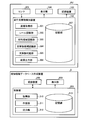
- FIG. 2 is a diagram illustrating an example of a functional configuration of a control unit of the traveling obstacle detection device and the detection area database creation device of the railway vehicle according to the present embodiment.
- FIG. 3 is a diagram for explaining an example of a detection area database creation process performed by the detection area database creation apparatus according to the present embodiment.
- FIG. 4 is a diagram for explaining an example of a detection area database creation process performed by the detection area database creation device according to the present embodiment.
- FIG. 5 is a diagram for explaining an example of a detection area database creation process performed by the detection area database creation device according to the present embodiment.
- FIG. 1 is a diagram illustrating an example of a configuration of a railway traveling safety support system according to the present embodiment.
- FIG. 2 is a diagram illustrating an example of a functional configuration of a control unit of the traveling obstacle detection device and the detection area database creation device of the railway vehicle according to the
- FIG. 6 is a diagram for explaining an example of a detection area database creation process performed by the detection area database creation apparatus according to the present embodiment.
- FIG. 7 is a diagram illustrating an example of a detection area database creation process performed by the detection area database creation apparatus according to the present embodiment.
- FIG. 8 is a diagram for explaining an example of a detection area database creation process performed by the detection area database creation apparatus according to the present embodiment.
- FIG. 9 is a diagram for explaining an example of a detection area database creation process performed by the detection area database creation device according to the present embodiment.
- FIG. 10 is a diagram illustrating an example of a database creation screen displayed on the detection area database creation device according to the present embodiment.
- FIG. 1 is a diagram showing an example of the configuration of the railway traveling safety support system according to the present embodiment.
- the railway traveling safety support system according to the present embodiment includes a railway vehicle RV and a detection area database creation device D, as shown in FIG.
- the railway vehicle RV and the detection area database creation device D can communicate various kinds of information with each other by wireless communication or the like.
- the railway vehicle RV includes a sensor 101, a traveling obstacle detection device 102, a recording device 103, a display unit 104, and a position measurement unit 105.
- the sensor 101 is an example of an imaging unit provided so as to be able to image the traveling direction of the railway vehicle RV.
- the traveling obstacle detection device 102 is an obstacle detection device that detects an object that obstructs traveling of the railway vehicle RV (hereinafter, referred to as an obstacle).
- the recording device 103 is a storage unit that stores detection results of obstacles by the traveling obstacle detection device 102.
- the display unit 104 displays various information such as a captured image obtained by capturing the traveling direction of the railway vehicle RV with the sensor 101 and a detection result of an obstacle by the traveling obstacle detection device 102.
- the position measuring unit 105 measures the traveling position of the railway vehicle RV.
- the travel of the railway vehicle RV is performed by using a speed generator (TG: Rate Generator), a satellite positioning system (GNSS: Global Navigation Satellite System), an acceleration sensor, a gyro sensor, or the like in the position measurement unit 105. Measure the position.
- the detection area database creation device D is a personal computer or the like. More specifically, the detection area database creation device D includes a control unit 201, a recording device 202, and a display unit 203, as shown in FIG.
- the control unit 201 controls the entire detection area database creation device D.
- the control unit 201 creates a database (hereinafter, referred to as a detection area database) that associates the target position with the detection area information.
- the target position is a traveling position of the railway vehicle RV that enlarges a region (hereinafter, referred to as a detection region) for detecting an obstacle in the captured image to a vehicle limit of the railway vehicle RV or an enlarged region outside the building limit. is there.
- the detection area information is information indicating the three-dimensional shape of the enlarged area at the target position.
- the recording device 202 stores various information such as a captured image obtained by capturing the image of the sensor 101 on which the railway vehicle RV is mounted.
- the display unit 203 is an LCD (Liquid Crystal Display) or the like, and displays a screen used for creating a detection area database (hereinafter, referred to as a database creation screen).
- FIG. 2 is a diagram illustrating an example of a functional configuration of the control unit of the traveling obstacle detection device and the detection area database creation device of the railway vehicle according to the present embodiment.
- the traveling obstacle detection device 102 included in the railway vehicle RV includes an image acquisition unit 301, a rail recognition unit 302, a detection area recognition unit 303, an obstacle candidate recognition unit 304, an obstacle determination unit 305, It has a result output unit 306.
- some or all of the image acquisition unit 301, the rail recognition unit 302, the detection area recognition unit 303, the obstacle candidate recognition unit 304, the obstacle determination unit 305, and the result output unit 306 are provided by the railway vehicle RV. Is realized by executing software stored in the recording device 103 or the like by a processor such as a CPU (Central Processing Unit) of the computer.
- a processor such as a CPU (Central Processing Unit) of the computer.
- Some or all of the image acquisition unit 301, the rail recognition unit 302, the detection region recognition unit 303, the obstacle candidate recognition unit 304, the obstacle determination unit 305, and the result output unit 306 are LSI (Large Scale Integration). , ASIC (Application Specific Integrated Circuit), FPGA (Field Programmable Gate Array), or other circuit board hardware.
- the image acquisition unit 301, the rail recognition unit 302, the detection area recognition unit 303, the obstacle candidate recognition unit 304, the obstacle determination unit 305, and the result output unit 306 cooperate with software executed by a processor and hardware. It may be realized by operation.
- the storage unit 307 includes a non-volatile storage medium such as a read only memory (ROM), a flash memory, a hard disk drive (HDD), and an SD card, and a volatile storage medium such as a random access memory (RAM) and a register. . Then, the storage unit 307 stores various information such as a detection area database.
- ROM read only memory
- HDD hard disk drive
- SD card Secure Digital Card
- RAM random access memory
- the image acquiring unit 301 acquires a captured image obtained by capturing the traveling direction of the railway vehicle RV by the sensor 101.
- the rail recognition unit 302 detects a rail on which the railway vehicle RV runs from the captured image.
- the detection area recognition unit 303 sets a three-dimensional detection area for a captured image with reference to the rail detected by the rail recognition unit 302.
- the detection area is a three-dimensional area including a specified area defined by a vehicle limit or a building limit of the railway vehicle RV in the captured image.
- the detection area recognition unit 303 enlarges the detection area to an enlarged area when the railway vehicle RV travels at the target position. Specifically, the detection area recognition unit 303 receives the detection area database from the detection area database creation device D in advance.
- the detection area database is a database that associates target positions (for example, kilometers or latitude and longitude) with detection area information indicating a three-dimensional shape of the enlarged area.
- the detection area database stores the positions of the turnouts (hereinafter, referred to as branch positions, for example, kilometers or latitude and longitude) existing on the route of the railway vehicle RV, and the railroads behind the turnouts.
- the route information indicating the route of the vehicle RV is associated with the route information.
- the detection area database includes a position of a tunnel existing on the route of the railway vehicle RV (hereinafter, referred to as a tunnel position; for example, about a kilometer or latitude and longitude).
- the detection area recognition unit 303 specifies, in the detection area database, detection area information that is associated with a target position that matches the travel position of the railway vehicle RV measured by the position measurement unit 105. Then, the detection area recognition unit 303 expands the detection area based on the specified detection area information so that the detection area includes the enlarged area at the target position.
- the detection region recognition unit 303 selects one of the plurality of routes after the branching device.
- the detection area is set only for the route indicated by the information.
- the detection region recognition unit 303 performs traveling by the position measurement unit 105.
- the position measurement method and the imaging conditions of the sensor 101 are changed.
- the detection region recognition unit 303 uses the method of measuring the traveling position by the position measuring unit 105 by using the satellite.
- the measurement method using the positioning system is switched to a measurement method using a speed generator, an acceleration sensor, or a gyro sensor.
- the detection area recognition unit 303 increases the sensitivity of the sensor 101 when the traveling position measured by the position measurement unit 105 matches the entrance of the tunnel included in the detection area database.
- the detection area recognition unit 303 sets the traveling position measurement method by the position measurement unit 105 to the satellite positioning system. Return to the measurement method used.
- the detection area recognition unit 303 lowers the sensitivity of the sensor 101.
- the obstacle candidate recognizing unit 304 extracts an object included in the detection area as an obstacle candidate (hereinafter, referred to as an obstacle candidate) based on the captured image in which the detection area is set.
- the obstacle determination unit 305 detects an obstacle from the obstacle candidates based on at least one of the size of the obstacle candidate extracted by the obstacle candidate recognition unit 304 and the movement vector of the obstacle candidate. I do.
- an object that is likely to be an obstacle can be detected as an obstacle, so that the detection accuracy of the obstacle can be improved.
- the result output unit 306 outputs the detection result of the obstacle by the obstacle determination unit 305.
- the result output unit 306 attaches the traveling position of the railway vehicle RV measured by the position measuring unit 105 when the captured image is obtained to the captured image obtained by the imaging of the sensor 101, and detects the captured image. It is transmitted to the area database creation device D.
- the detection area database creation device D includes an acquisition unit 310, a creation unit 311, an output unit 312, and a storage unit 313.
- some or all of the acquisition unit 310, the creation unit 311, and the output unit 312 are configured such that a processor such as a CPU included in the detection area database creation device D executes software stored in the recording device 202. Is realized by:
- the acquisition unit 310, the creation unit 311, and the output unit 312 may be realized by hardware that is a circuit board such as an LSI, an ASIC, and an FPGA.
- the acquisition unit 310, the creation unit 311, and the output unit 312 may be realized by cooperation of software executed by a processor and hardware.
- the storage unit 313 includes a non-volatile storage medium such as a ROM, a flash memory, an HDD, and an SD card, and a volatile storage medium such as a RAM and a register.
- the storage unit 313 stores various information such as a detection area database.
- the acquisition unit 310 acquires, from the railway vehicle RV, the captured image and the traveling position of the railway vehicle RV when the captured image is obtained. Then, the acquisition unit 310 associates the acquired captured image with the traveling position of the railway vehicle RV at the time when the captured image is obtained, and stores the acquired image in the recording device 202. For example, the acquisition of information from the railway vehicle RV may be performed off-line at a depot or a station after a predetermined travel has been performed, or may be performed in real time via a wireless line during travel. May be.
- the creation unit 311 creates a detection area database based on the captured image stored in the recording device 202 in association with the traveling position of the railway vehicle RV. Then, the creation unit 311 stores the created detection area database in the storage unit 313.
- a detection area database can be created based on information (for example, the height and width of the platform of the station) of a target position that cannot be confirmed from an image (for example, an aerial photograph) of the traveling section of the railway vehicle RV captured from above. Therefore, it is possible to create a detection area database that can detect obstacles of the railway vehicle RV with high accuracy.
- FIG. 3 is a diagram for explaining an example of a detection area database creation process performed by the detection area database creation apparatus according to the present embodiment.
- the detection area database associates target positions (for example, kilometers) with detection area information.
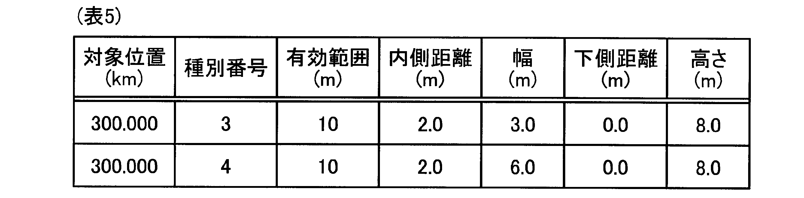
- the detection area information includes a type number, an effective range N1, an inner distance N2, a width N3, a lower distance N4, and a height N5.
- the detection area information may include position information of the enlarged area at the target position.
- the detection area information is position information indicating whether the enlarged area is located on the right side or the left side in the width direction X (see FIG. 3) of the railway vehicle RV with reference to the rail R on which the railway vehicle RV runs. May be included.
- the detection area database may include transmission position information that can specify a transmission position at which the detection area database is transmitted to the railway vehicle RV, in association with the target position.
- the type number indicates the station platform on the left side (opposite platform) in the traveling direction of the railway vehicle RV, the station platform on the right side (island platform) in the traveling direction of the railway vehicle RV, and the traveling direction of the railway vehicle RV.
- the number indicates the type of the target position, such as a circuit breaker on the left side, a circuit breaker on the right side in the traveling direction of the railway vehicle RV, a sign, a signal, a tunnel, an iron bridge, and the like.
- the detection area database creation device D stores in advance a type database (see Table 2 below) that associates the type number with the type of the target position in the storage unit 313 or the like. Then, when the user of the detection area database creation device D creates the detection area database, the creation unit 311 displays the type database on the display unit 203 so that the type database can be referred to.
- the effective range N1 is the depth of the enlarged area E existing outside the defined area T (the vehicle limit T1 or the building limit T2), in other words, the enlarged area E in the traveling direction Z of the railway vehicle RV.
- the inner distance N2 is a distance from an intermediate point between the rails R in the width direction X of the railway vehicle RV to an inner end of the enlarged area E, as shown in FIG.
- the width N3 is the width of the enlarged area E in the width direction X of the railway vehicle RV, as shown in FIG.
- the lower distance N4 is a distance from the rail R to the lower end of the enlarged area E in the height direction Y of the railway vehicle RV, as shown in FIG.
- the height N5 is the height of the enlarged area E in the height direction Y of the railway vehicle RV, as shown in FIG.
- the creation unit 311 causes the display unit 203 to display a screen including a captured image and an input field (hereinafter, referred to as a database creation screen).
- the input field is a field for displaying the target position and the detection area information input by the user of the detection area database creation device D.
- the user of the detection area database creation device D can input the target position and the detection area information while checking the captured image displayed on the display unit 203, thereby facilitating the creation of the detection area database. can do.
- the creating unit 311 creates a detection area database that associates the target position input using the input field with the detection area information.
- the creating unit 311 detects an image serving as a symbol of the target position (hereinafter, referred to as a target position image) from the captured image by the image recognition processing. Specifically, the creating unit 311 detects, as a target position image, a fence of a station platform, a railroad crossing, a dedicated sign, a signal, and the like, from the captured image. In the present embodiment, the creating unit 311 generates an image serving as a symbol of a target position existing a predetermined distance (for example, 30 m) from the tip of the railway vehicle RV in the traveling direction Z of the railway vehicle RV. It is detected as the target position image.
- a predetermined distance for example, 30 m
- the creating unit 311 causes the display unit 203 to display detection information indicating that the target position image has been detected (for example, a message indicating that the target position image has been detected).
- detection information indicating that the target position image has been detected for example, a message indicating that the target position image has been detected.
- the creating unit 311 causes the display unit 203 to display a preview image in which a detection area image, which is an image indicating the detection area, is superimposed on the captured image based on the created detection area database.
- a detection area image which is an image indicating the detection area
- the creating unit 311 causes the display unit 203 to display a preview image in which a detection area image, which is an image indicating the detection area, is superimposed on the captured image based on the created detection area database.
- the creation unit 311 causes the display unit 203 to display a database creation screen including map information.
- the map information is a map that can specify the traveling position of the railway vehicle RV when the captured image is obtained. Accordingly, the user of the detection area database creation device D can perform the creation work of the detection area database while checking the entire traveling section of the railway vehicle RV based on the map information displayed on the display unit 203. The work of creating the area database can be facilitated.
- the output unit 312 transmits (outputs) the detection area database stored in the storage unit 313 to the railway vehicle RV.
- the output unit 312 determines when the railway vehicle RV reaches the transmission position indicated by the transmission position information (for example, a position 200 m before the target position). Then, the detection area database including the target position and the detection area information associated with the transmission position information is transmitted to the railway vehicle RV.
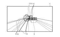
- FIG. 4 is a diagram for explaining an example of a detection area database creation process performed by the detection area database creation device according to the present embodiment.
- the creating unit 311 detects the platform fence of the station included in the captured image F as the target position image S, and displays detection information indicating that the target position image S has been detected on the display unit 203. To be displayed. Then, as illustrated in FIG. 4, when the detected target position image S is the image of the facing platform, the creating unit 311 determines the target position and the specified region T (the vehicle limit T1 or the vehicle limit T1) in the traveling direction Z of the railway vehicle RV.
- a detection area database (see Table 3 below) that associates the detection area information of the enlarged area E existing on the left side of the building limit T2) is created.
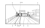
- FIG. 5 is a diagram for explaining an example of a detection area database creation process performed by the detection area database creation device according to the present embodiment.
- the creating unit 311 detects the platform fence included in the captured image F as the target position image S, and displays the detection information indicating that the target position image S has been detected on the display unit 203. To be displayed. Then, as illustrated in FIG. 5, when the detected target position image S is an image of the island-type platform, the creating unit 311 determines the target region and the specified region T (the vehicle limit T1 or the vehicle limit T1) in the traveling direction Z of the railway vehicle RV.
- a detection area database (see Table 4 below) that associates the detection area information of the enlarged area E existing on the right side of the building limit T2) is created.
- FIG. 6 is a diagram for explaining an example of a detection area database creation process performed by the detection area database creation apparatus according to the present embodiment.
- the creating unit 311 detects the circuit breaker included in the captured image F as the target position image S, and displays detection information indicating that the target position image S has been detected on the display unit 203. Let it. Then, as illustrated in FIG. 6, when the detected target position image S is a barrier, the creating unit 311 determines the target position and the enlarged area existing on both sides of the specified area T (the vehicle limit T1 or the building limit T2).
- a detection area database (see Table 5 below) that associates the detection area information with E is created.
- the creating unit 311 expands the rail side laid in parallel with the rail on which the railway vehicle RV runs. It is assumed that the width of the area E is longer than the width of the enlarged area E on the rail side on which the railroad vehicle RV runs. For example, when the left-hand traffic is adopted, the creating unit 311 increases the width of the enlarged area E existing on the right side in the traveling direction Z of the railway vehicle RV by increasing the width of the enlarged area E existing on the left side in the traveling direction Z of the railway vehicle RV. It is longer than the width of the region E.
- FIG. 7 is a diagram illustrating an example of a detection area database creation process performed by the detection area database creation apparatus according to the present embodiment.
- the creating unit 311 detects the branching device BG included in the captured image F as illustrated in FIG.
- the creating unit 311 includes route information (for example, a type number indicating straight ahead) that can specify a route on which the railroad vehicle RV travels among routes ahead of the branching device BG.
- route information for example, a type number indicating straight ahead
- a detection area database see Table 6 below
- the detection area recognition unit 303 included in the railway vehicle RV sets the detection area in the captured image F, it is possible to set the detection area only for the traveling path of the railway vehicle RV. It is possible to more accurately detect obstacles that may hinder the traveling of the vehicle.
- the branching position of the branching device BG is a preset distance (about km) from the station to the branching device.
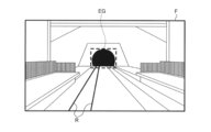
- FIG. 8 is a diagram for explaining an example of a detection area database creation process performed by the detection area database creation apparatus according to the present embodiment.
- the creating unit 311 detects the entrance EG of the tunnel included in the captured image F as illustrated in FIG.
- the creation unit 311 detects the tunnel area including tunnel information that associates the type number indicating the tunnel entrance EG with the tunnel entrance position that is the position of the tunnel entrance EG. Create a database (see Table 7 below).
- the sensitivity of the sensor 101 of the railway vehicle RV is increased to increase the detection accuracy of obstacles using the captured image F, and the traveling position of the railway vehicle RV can be measured by a method. It is possible to switch from a measurement method using a satellite positioning system to a measurement method using an acceleration sensor, a gyro sensor, or the like.
- FIG. 9 is a diagram for explaining an example of a detection area database creation process performed by the detection area database creation device according to the present embodiment.
- the creating unit 311 detects a tunnel exit OG included in the captured image F.
- the creation unit 311 detects the detection area including the tunnel information that associates the type number indicating the tunnel exit OG with the tunnel exit position that is the position of the tunnel exit OG. Create a database (see Table 8 below).
- the sensitivity of the sensor 101 of the railway vehicle RV is reduced to prevent overexposure of the captured image F, and a method of measuring the traveling position of the railway vehicle RV is implemented by a satellite positioning system. It is possible to return to the used measurement method.
- FIG. 10 is a diagram showing an example of a database creation screen displayed on the detection area database creation device according to the present embodiment.
- the creating unit 311 causes the display unit 203 to display a database creating screen G including a moving image G1, an input column G2, map information G3, and various buttons B1 to B7.
- the rewind button B1 is a button for instructing rewind of the moving image G1 (an example of a captured image) displayed on the database creation screen G.
- the frame return button B2 is a button for instructing frame return of the moving image G1.
- the stop button B3 is a button for instructing stop of reproduction of the moving image G1.
- the frame advance button B4 is a button for instructing frame advance of the moving image G1.
- the pause button B5 is a button for instructing a pause of the reproduction of the moving image G1.
- the fast forward button B6 is a button for instructing the fast forward of the moving image G1.
- the creation instruction button B7 is a button for instructing creation of a detection area database.
- the creation unit 311 causes the display unit 203 to display the database creation screen G including the moving image G1 according to the operation of the various buttons B1 to B6. At that time, as illustrated in FIG. 10, the creating unit 311 determines, for each frame forming the moving image G1, the traveling position of the railway vehicle RV when the frame is obtained by the sensor 101 of the railway vehicle RV (for example, , Latitude and longitude, kilometers) and location date and time information I1 indicating date and time.
- the creating unit 311 determines a position at which the target position image is detected in each frame configuring the moving image G1 (for example, from the tip of the railway vehicle RV in the traveling direction of the railway vehicle RV in advance).
- a reference line L drawn in the width direction X of the railway vehicle RV is displayed at a set distance (for example, 30 m ahead).
- the map information G3 is a map including the traveling position of the railway vehicle RV when the moving image G1 is obtained.
- the creating unit 311 includes a travel position display P indicating the travel position of the railroad vehicle RV in the map information G3, as shown in FIG. Thereby, the user of the detection area database creation device D can perform the creation work of the detection area database while confirming the entire traveling section of the railway vehicle RV based on the map information G3. It can be facilitated.
- the input field G2 includes an index of the detection area database, a target position (for example, latitude and longitude, kilometers), and detection area information (for example, type number, effective range, inside distance, width, lower distance, height, This is a column for displaying the station / facility information, which is information on the station or facility to which the target position belongs, and the transmission position information in association with each other.
- a target position for example, latitude and longitude, kilometers
- detection area information for example, type number, effective range, inside distance, width, lower distance, height
- the creating unit 311 sets the target position, the detection area information, And default values of the transmission position information.
- the default value of the target position is a traveling position that is a preset distance (for example, 30 m) away from the traveling position of the railway vehicle RV when the moving image G1 is obtained.
- the default value of the transmission position information is a traveling position that is a predetermined distance (for example, 200 m) before the traveling position of the railroad vehicle RV when the moving image G1 is obtained.
- the default value of the detection area information is the detection area information set in advance for each type of the target position.
- the user of the detection area database creation device D inputs the target position, the detection area information, and the transmission position information while referring to the target position, the detection area information, and the default value of the transmission position information displayed in the input field G2. G2 can be input. Thereafter, when the creation instruction button B7 is pressed to instruct creation of the detection area database, the creation unit 311 associates the target position input in the input field G2, the detection area information, and the transmission position information. Create the attached detection area database.
- the creation unit 311 creates the detection area database including the detection area information input to the input field G2. However, the creation unit 311 automatically creates the detection area database based on the captured image and the traveling position. Anything should do. For example, the creating unit 311 determines, as a target position, a traveling position that is a distance ahead of a traveling position of the railway vehicle RV when the captured image is obtained. Further, the creating unit 311 converts the shape of the enlarged area (for example, a rectangular area) specified by the user of the detection area database creating apparatus D into the actual size of the enlarged area in the real space on the captured image. Then, the creation unit 311 may create a database that associates the determined target position with the detection area information indicating the actual size of the enlarged area as the detection area database.
- the creating unit 311 may create a database that associates the determined target position with the detection area information indicating the actual size of the enlarged area as the detection area database.
- the detection region database can be created based on the information on the target position that cannot be confirmed from the image taken from above of the traveling section of the railway vehicle RV.
- the detection region database can be created based on the information on the target position that cannot be confirmed from the image taken from above of the traveling section of the railway vehicle RV.
Landscapes
- Engineering & Computer Science (AREA)
- Mechanical Engineering (AREA)
- Train Traffic Observation, Control, And Security (AREA)
- Information Retrieval, Db Structures And Fs Structures Therefor (AREA)
- Image Analysis (AREA)
Abstract
Description







Claims (6)
- 鉄道車両から、当該鉄道車両が有する撮像部によって前記鉄道車両の進行方向を撮像して得られる撮像画像、および当該撮像画像が得られた際の前記鉄道車両の走行位置を取得する取得部と、
前記撮像画像および前記走行位置に基づいて、前記撮像画像内において前記鉄道車両の走行の支障となる支障物を検知する検知領域を前記鉄道車両の車両限界または建築限界の外側の拡大領域まで拡大する前記走行位置である対象位置と、前記拡大領域の三次元の形状を示す検知領域情報と、を対応付ける検知領域データベースを作成する作成部と、
を備える検知領域データベース作成装置。 - 前記作成部は、前記撮像画像と、前記対象位置および前記検知領域情報を入力可能な入力欄と、を含む画面を表示部に表示させ、前記入力欄を用いて入力される前記検知領域情報と前記対象位置とを対応付ける前記検知領域データベースを作成する請求項1に記載の検知領域データベース作成装置。
- 前記作成部は、さらに、画像認識処理によって、前記撮像画像から、前記対象位置を示す対象位置画像を検出し、かつ前記対象位置画像が検出されたことを示す検出情報を前記表示部に表示させる請求項2に記載の検知領域データベース作成装置。
- 前記作成部は、さらに、作成した前記検知領域データベースに基づいて、前記撮像画像に対して、前記検知領域を示す検知領域画像を重畳したプレビュー画像を前記表示部に表示させる請求項2または3に記載の検知領域データベース作成装置。
- 前記作成部は、さらに、画像認識処理によって、前記撮像画像から、前記鉄道車両の進路に存在する分岐器を検出し、当該検出された分岐器の後の前記鉄道車両の進路を示す進路情報を含む前記検知領域データベースを作成する請求項1から4のいずれか一に記載の検知領域データベース作成装置。
- 前記作成部は、前記撮像画像が得られた際の前記走行位置を特定可能な地図情報を含む前記画面を前記表示部に表示させる請求項2から4のいずれか一に記載の検知領域データベース作成装置。
Priority Applications (3)
| Application Number | Priority Date | Filing Date | Title |
|---|---|---|---|
| SG11202012907UA SG11202012907UA (en) | 2018-06-26 | 2019-06-25 | Detection-region database creating device |
| CN201980042667.9A CN112399942B (zh) | 2018-06-26 | 2019-06-25 | 检测区域数据库制作装置 |
| EP19824624.1A EP3816013A4 (en) | 2018-06-26 | 2019-06-25 | DEVICE FOR GENERATION OF A DETECTION AREA |
Applications Claiming Priority (2)
| Application Number | Priority Date | Filing Date | Title |
|---|---|---|---|
| JP2018120441A JP7068068B2 (ja) | 2018-06-26 | 2018-06-26 | 検知領域データベース作成装置 |
| JP2018-120441 | 2018-06-26 |
Publications (1)
| Publication Number | Publication Date |
|---|---|
| WO2020004424A1 true WO2020004424A1 (ja) | 2020-01-02 |
Family
ID=68986689
Family Applications (1)
| Application Number | Title | Priority Date | Filing Date |
|---|---|---|---|
| PCT/JP2019/025250 Ceased WO2020004424A1 (ja) | 2018-06-26 | 2019-06-25 | 検知領域データベース作成装置 |
Country Status (5)
| Country | Link |
|---|---|
| EP (1) | EP3816013A4 (ja) |
| JP (1) | JP7068068B2 (ja) |
| CN (1) | CN112399942B (ja) |
| SG (1) | SG11202012907UA (ja) |
| WO (1) | WO2020004424A1 (ja) |
Cited By (2)
| Publication number | Priority date | Publication date | Assignee | Title |
|---|---|---|---|---|
| CN116128834A (zh) * | 2023-02-01 | 2023-05-16 | 河南理工大学 | 基于三维激光扫描的轨道交通站台限界快速检测方法 |
| CN117575443A (zh) * | 2024-01-17 | 2024-02-20 | 金华市浙中公铁联运港有限公司 | 一种铁路场站停靠区域智能管理方法及系统 |
Families Citing this family (4)
| Publication number | Priority date | Publication date | Assignee | Title |
|---|---|---|---|---|
| JP7721406B2 (ja) * | 2021-11-12 | 2025-08-13 | 株式会社東芝 | 情報処理装置及びプログラム |
| JP2024099137A (ja) * | 2023-01-12 | 2024-07-25 | 東芝インフラシステムズ株式会社 | 鉄道車両制御システム、及び鉄道車両制御方法 |
| WO2025069359A1 (ja) * | 2023-09-29 | 2025-04-03 | 日本電気株式会社 | 判定システム、判定方法及び記録媒体 |
| CN120440090B (zh) * | 2025-07-14 | 2025-11-25 | 湖南中车时代通信信号有限公司 | 一种列车进轨控制方法、装置、设备及介质 |
Citations (3)
| Publication number | Priority date | Publication date | Assignee | Title |
|---|---|---|---|---|
| JPH0710003A (ja) * | 1993-04-28 | 1995-01-13 | East Japan Railway Co | 鉄道車両用支障物検知装置 |
| JP2016052849A (ja) | 2014-09-04 | 2016-04-14 | 公益財団法人鉄道総合技術研究所 | 障害物検出装置及び方法 |
| JP2019084881A (ja) * | 2017-11-02 | 2019-06-06 | 株式会社東芝 | 支障物検知装置 |
Family Cites Families (7)
| Publication number | Priority date | Publication date | Assignee | Title |
|---|---|---|---|---|
| JPH07119560B2 (ja) * | 1991-05-27 | 1995-12-20 | 東海旅客鉄道株式会社 | トンネル断面管理装置 |
| JP2002008019A (ja) * | 2000-06-21 | 2002-01-11 | Fuji Heavy Ind Ltd | 軌道認識装置及び軌道認識装置を用いた鉄道車両 |
| DE102014206473A1 (de) * | 2014-04-03 | 2015-10-08 | Bombardier Transportation Gmbh | Automatische Assistenz eines Fahrers eines fahrspurgebundenen Fahrzeugs, insbesondere eines Schienenfahrzeugs |
| DE102014220778A1 (de) * | 2014-10-14 | 2016-04-14 | Robert Bosch Gmbh | Verfahren zum Überwachen von Gleisabschnitten bei einem Schienenfahrzeug |
| CN104777521A (zh) * | 2015-03-24 | 2015-07-15 | 广州市地下铁道总公司 | 一种基于双目视觉的列车车门与站台屏蔽门之间异物检测系统及其检测方法 |
| JP6346868B2 (ja) * | 2015-03-31 | 2018-06-20 | 公益財団法人鉄道総合技術研究所 | ステレオ画像処理方法およびその装置 |
| JP6428713B2 (ja) * | 2015-07-29 | 2018-11-28 | 株式会社デンソー | 情報表示装置 |
-
2018
- 2018-06-26 JP JP2018120441A patent/JP7068068B2/ja active Active
-
2019
- 2019-06-25 WO PCT/JP2019/025250 patent/WO2020004424A1/ja not_active Ceased
- 2019-06-25 SG SG11202012907UA patent/SG11202012907UA/en unknown
- 2019-06-25 CN CN201980042667.9A patent/CN112399942B/zh active Active
- 2019-06-25 EP EP19824624.1A patent/EP3816013A4/en active Pending
Patent Citations (3)
| Publication number | Priority date | Publication date | Assignee | Title |
|---|---|---|---|---|
| JPH0710003A (ja) * | 1993-04-28 | 1995-01-13 | East Japan Railway Co | 鉄道車両用支障物検知装置 |
| JP2016052849A (ja) | 2014-09-04 | 2016-04-14 | 公益財団法人鉄道総合技術研究所 | 障害物検出装置及び方法 |
| JP2019084881A (ja) * | 2017-11-02 | 2019-06-06 | 株式会社東芝 | 支障物検知装置 |
Cited By (4)
| Publication number | Priority date | Publication date | Assignee | Title |
|---|---|---|---|---|
| CN116128834A (zh) * | 2023-02-01 | 2023-05-16 | 河南理工大学 | 基于三维激光扫描的轨道交通站台限界快速检测方法 |
| CN116128834B (zh) * | 2023-02-01 | 2025-07-01 | 河南理工大学 | 基于三维激光扫描的轨道交通站台限界快速检测方法 |
| CN117575443A (zh) * | 2024-01-17 | 2024-02-20 | 金华市浙中公铁联运港有限公司 | 一种铁路场站停靠区域智能管理方法及系统 |
| CN117575443B (zh) * | 2024-01-17 | 2024-04-19 | 金华市浙中公铁联运港有限公司 | 一种铁路场站停靠区域智能管理方法及系统 |
Also Published As
| Publication number | Publication date |
|---|---|
| JP7068068B2 (ja) | 2022-05-16 |
| EP3816013A1 (en) | 2021-05-05 |
| JP2020001476A (ja) | 2020-01-09 |
| CN112399942B (zh) | 2023-09-08 |
| SG11202012907UA (en) | 2021-02-25 |
| EP3816013A4 (en) | 2022-03-23 |
| CN112399942A (zh) | 2021-02-23 |
Similar Documents
| Publication | Publication Date | Title |
|---|---|---|
| JP7068068B2 (ja) | 検知領域データベース作成装置 | |
| JP7062407B2 (ja) | 支障物検知装置 | |
| US8532917B2 (en) | Method, system, and recording medium for navigating vehicle | |
| CN101424538B (zh) | 车辆用导航装置以及车辆用导航方法 | |
| JP3958133B2 (ja) | 車両位置測定装置および方法 | |
| WO2016159171A1 (ja) | 自動運転支援システム、自動運転支援方法及びコンピュータプログラム | |
| CN105929190A (zh) | 确定车辆速度的方法和系统 | |
| WO2016159172A1 (ja) | 自動運転支援システム、自動運転支援方法及びコンピュータプログラム | |
| JP6855712B2 (ja) | 分岐器進入可否判定装置及び分岐器進入可否判定方法 | |
| JP2005207999A (ja) | ナビゲーション装置及び交差点案内方法 | |
| JPWO2014188536A1 (ja) | ナビゲーション装置 | |
| JP2016060336A (ja) | 自動運転支援システム、自動運転支援方法及びコンピュータプログラム | |
| JP2004257979A (ja) | ナビゲーション装置 | |
| JP7364093B2 (ja) | 路面管理装置、路面管理システム、端末装置、路面管理方法、及び、プログラム | |
| KR20100010298A (ko) | 경로 안내 방법 및 장치 | |
| JP5464878B2 (ja) | ナビゲーション装置および車線減少予測案内方法 | |
| JP2010032243A (ja) | ナビゲーション装置 | |
| WO2007088915A1 (ja) | 経路誘導装置、経路誘導方法、経路誘導プログラムおよび記録媒体 | |
| JP2018206014A (ja) | 交通情報取得装置、交通情報取得システム、交通情報取得方法、および交通情報取得プログラム | |
| JP2014173956A (ja) | 経路案内装置、及び経路案内プログラム | |
| JP2009156758A (ja) | ナビゲーション装置及びコンピュータプログラム | |
| WO2007123159A1 (ja) | 経路誘導装置、経路誘導方法、経路誘導プログラムおよびコンピュータに読み取り可能な記録媒体 | |
| JP2020075663A (ja) | 位置推定装置、位置推定方法、位置推定プログラム | |
| JP2023112536A (ja) | 路面損傷位置の算定方法 | |
| KR100818323B1 (ko) | 과속차량 검출시스템 및 과속차량 검출방법 |
Legal Events
| Date | Code | Title | Description |
|---|---|---|---|
| 121 | Ep: the epo has been informed by wipo that ep was designated in this application |
Ref document number: 19824624 Country of ref document: EP Kind code of ref document: A1 |
|
| NENP | Non-entry into the national phase |
Ref country code: DE |
|
| ENP | Entry into the national phase |
Ref document number: 2019824624 Country of ref document: EP Effective date: 20210126 |
|
| WWG | Wipo information: grant in national office |
Ref document number: 11202012907U Country of ref document: SG |
|
| WWP | Wipo information: published in national office |
Ref document number: 11202012907U Country of ref document: SG |