WO2020006709A1 - 视觉定位系统、无人机以及自检测无人机自身位置的方法 - Google Patents
视觉定位系统、无人机以及自检测无人机自身位置的方法 Download PDFInfo
- Publication number
- WO2020006709A1 WO2020006709A1 PCT/CN2018/094501 CN2018094501W WO2020006709A1 WO 2020006709 A1 WO2020006709 A1 WO 2020006709A1 CN 2018094501 W CN2018094501 W CN 2018094501W WO 2020006709 A1 WO2020006709 A1 WO 2020006709A1
- Authority
- WO
- WIPO (PCT)
- Prior art keywords
- module
- data
- series
- images
- drone
- Prior art date
- Legal status (The legal status is an assumption and is not a legal conclusion. Google has not performed a legal analysis and makes no representation as to the accuracy of the status listed.)
- Ceased
Links
Images


Classifications
-
- G—PHYSICS
- G01—MEASURING; TESTING
- G01C—MEASURING DISTANCES, LEVELS OR BEARINGS; SURVEYING; NAVIGATION; GYROSCOPIC INSTRUMENTS; PHOTOGRAMMETRY OR VIDEOGRAMMETRY
- G01C21/00—Navigation; Navigational instruments not provided for in groups G01C1/00 - G01C19/00
Definitions
- the invention relates to a visual positioning system, a drone, and a method for self-detecting the position of the drone.
- Unmanned aerial vehicle is a remotely controlled flight or autonomous aircraft carrying a camera, sensor, communication device or other payload.
- UAV Unmanned aerial vehicle
- GPS global positioning system
- the technical problem to be solved by the present disclosure is to provide a drone with a positioning system other than GPS to overcome the disadvantage that GPS positioning information may be inaccurate in many different situations.
- the present disclosure solves the above technical problems through the following technical solutions.
- a vision positioning system for a drone includes a lens module, a matching module, a sensor module, and a translation module.
- the lens module captures a series of fish-eye view images over time during the flight.
- the matching module derives the first data by comparing and contrasting at least one feature from the fisheye view image.
- the sensor module collects the second data, and the sensor module is electrically coupled to the lens module.
- the translation module is electrically coupled to the sensor module to generate positioning data by processing the first data in consideration of the second data.
- the sensor module includes one or more of a LiDAR sensor, an inertial measurement unit (IMU), a GPS receiver, and a radar.
- IMU inertial measurement unit
- the lens module includes a fisheye lens having a field of view of at least 180 degrees.
- the second data includes one or more of altitude data, GPS maps, GPS coordinates, positions relative to at least one surrounding physical object.
- the sensor module includes one or more of a LiDAR and a GPS receiver.
- an unmanned aerial vehicle (UAV)
- the drone includes a body, a fisheye lens module, a matching module, and a translation module.
- the body has a lower side.
- the fisheye lens module is disposed on the lower side of the drone.
- the fisheye lens module has a wide field of view and takes a series of images of the area under the drone over time during the flight.
- the matching module compares and contrasts the features of each of the series of images to derive the first data.
- the translation module translates the first data into positioning data.
- the drone further includes a verification module that compares the positioning data with a GPS map.
- the drone further includes a gimbal that connects the fisheye lens module to the body, the gimbal having at most 2 axes .
- the series of images taken over time are taken at a speed of at least 60 images per second.
- the drone further includes a sensor module, the sensor module is configured to collect second data, and the translation module is configured to consider the second data to derive the positioning data.
- the sensor module includes one or more of a LiDAR sensor, an inertial measurement unit (IMU), a GPS receiver, and a radar.
- a method for self-detecting the position of the drone when flying in an area with insufficient GPS signals includes: obtaining initial positioning data including altitude data; capturing a series of fish-eye view images during flight at a speed of more than 60 images per second; comparing relative changes between the series of fish-eye view images; The initial positioning data and the relative change calculate the position of the drone.
- the method further includes using data from the IMU.
- the method further includes comparing the relative change to a GPS map.
- a visual positioning system may be used in a drone to allow the drone to have additional / alternative positioning information.
- the UAV of the present invention uses the visual positioning system as a supplementary method on the existing positioning system, and can obtain more accurate positioning information.
- FIG. 1 is a side view of a UAV according to some embodiments of the present disclosure.
- FIG. 2 is a block diagram of a UAV according to some embodiments of the present disclosure.
- FIG. 3 is a side view of a lens module according to some embodiments of the present disclosure.
- FIG. 4 illustrates a two-dimensional view of diffusion of various points shown in a lens module according to some embodiments of the present disclosure.
- FIG. 5 illustrates four images taken by a lens module, which represent four views of the ground over time, according to some embodiments of the present disclosure.
- FIG. 6 is a perspective view of a lens module on a 2-axis universal joint according to some embodiments of the present disclosure.
- FIG. 7 is a block diagram of a UAV according to some embodiments of the present disclosure.
- FIG. 8 is a block diagram of a UAV according to some embodiments of the present disclosure.
- FIG. 9 is a method of self-detecting a position of a drone itself according to some embodiments of the present disclosure.
- the invention discloses a new way to improve the integrity and effectiveness of position detection of a drone by using a positioning system.
- the positioning system may be a visual positioning system.
- the visual positioning system may generate a visual position, such as a relative position with respect to a reference point or point block of the drone.
- the visual location may differ from the location defined by the Global Positioning System (GPS).
- GPS Global Positioning System
- a new method for self-detecting the relative position of the drone with respect to a reference point or a point block when flying over an area where GPS signals are insufficient is also provided.
- a visual positioning system may be used in an unmanned aerial vehicle (UAV) to obtain additional / alternative positioning information.
- UAV unmanned aerial vehicle
- additional / alternative positioning information can be used to locate the UAV.
- the visual positioning system may capture an image (photo and / or video) of the ground during the flight, and process the image (photo and / or video) in real time to obtain positioning information.
- the visual positioning system may select at least one reference object in the image and analyze the image to calculate the positioning information of the UAV based on the reference object.
- a visual positioning system can be used as a supplementary way to existing positioning systems, and therefore drones can acquire more Accurate positioning information.
- a drone having a visual positioning system according to one or more embodiments of the present disclosure can obtain accurate positioning even when flying in a place where GPS signals are limited or reception is poor, such as when flying between high-rise buildings and structures. information.
- FIG. 1 is a side view of an unmanned aerial vehicle (UAV) 100 according to some embodiments of the present disclosure.
- FIG. 2 is a block diagram of a UAV 100 according to some embodiments of the present disclosure.
- the UAV 100 or UAV is a multi-rotor aircraft.
- UAV 100 can be three-rotor, four-rotor, six-rotor, eight-rotor or other multi-rotor aircraft.
- the UAV 100 includes a body 101, a lens module 102, a matching module 103, and a translation module 104.
- the lens module 102 combined with the matching module 103 and the translation module 104 may be a visual positioning system.
- the matching module 103 and the translation module 104 may be arranged inside the body 101. In one or more embodiments, the matching module 103 and the translation module 104 may be arranged outside the body 101.
- the matching module 103 and the translation module 104 may be provided together with the lens module 102.
- the matching module 103 may be provided together with the lens module 102, and the translation module 104 may be provided within the body 101, and vice versa.
- the body 101 may have different shapes and structures according to the design or needs of the user.
- the body 101 has a lower side 1011.
- the underside 1011 is the bottom of the UAV 100 that faces the ground during the flight of the UAV 100.
- the lens module 102 is disposed on the lower side 1011 of the UAV 100 and is mounted on the bottom surface of the UAV 100.
- the lens module 102 may include a lens unit 1021 and an image sensor unit 1022 connected to each other.
- the image sensor unit 1022 is configured to sense an incident light signal from the lens unit 1021 to generate a series of fish-eye view images.
- the lens unit 1021 includes a wide-angle lens, an ultra-wide-angle lens, or a combination thereof.
- the wide-angle lens includes at least one lens having a field of view of at most 180 degrees.
- the ultra-wide-angle lens unit includes at least one lens having a field of view of at least 180 degrees.
- the ultra-wide-angle lens may be a fisheye lens.
- the lens module 102 may be considered a fisheye lens module.
- the image sensor unit 1022 may include a CCD (Charge Coupled Device) image sensor, a CMOS (Complementary Metal Oxide Semiconductor) image sensor, or a combination thereof.
- the lens module 102 may be controlled to capture or capture a series of images (photos and / or videos) I of the area (eg, the ground area) below the UAV 100 over time during the flight.
- Each image in the series of images I may include reference points or point blocks on the ground area.
- the reference point block may be a specific building or tree on the ground area.
- the series of images I may be a series of fish-eye view images.
- the series of images (photos and / or videos) I captures at least 60 images per second.
- the lens module 102 may start capturing images (photos and / or videos) I.
- the signal strength of the initial positioning information is lower than a predetermined factor.
- the lens module 102 may capture images (photos and / or videos) I from the beginning of the flight, or may not capture images (photos and / or videos) I from the beginning of the flight.
- the lens module 102 may take images (photos and / or videos) I during a predetermined period of time in flight.
- the lens module 102 may capture images (photos and / or videos) I when certain predetermined factors are met, such as when a predetermined height is reached.
- FIG. 3 is a side view of a lens module 102 according to some embodiments of the present disclosure.
- the lens module 102 may include an ultra-wide-angle lens, such as a fisheye lens.
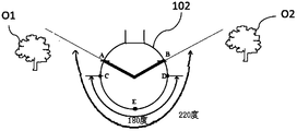
- the fisheye lens may have a field of view of 220 degrees (such as the coverage of points A to E to B along the circumference in FIG. 3).
- a fisheye lens may capture two distant objects O1 and O2 in FIG. 3.
- the lens module 102 can take a single image I with a 220-degree field of view.
- FIG. 4 illustrates an expanded two-dimensional view 400 of various points shown in the lens module 102 according to some embodiments of the present disclosure. As shown in FIG.
- a two-dimensional illustration of an image of the lens module 102 having a 220-degree field of view and points A, B (as shown in FIG. 3) are shown due to such a wide field of view.
- the lens module 102 can capture an image I having a wider field of view through an ultra-wide-angle lens such as a fisheye lens.
- the lens module 102 can also capture a single image I (such as coverage along points C to E to D along the circumference in FIG. 3) with a 180-degree field of view.
- the lens module 102 may include a wide-angle lens as needed.
- these are just examples and are not intended to be limiting.
- various field angles other than 220 degrees and 180 degrees are also considered.
- the UAV 100 may tilt during flight, which causes the lens module 102 to tilt as well.
- the lens module 102 has a wider field of view.
- the captured image I may contain sufficient ground information to calculate the additional / alternative positioning information of the UAV 100.
- reference point blocks on the ground area are always included in the series of images I, where the reference point blocks are used to calculate additional / alternative positioning information for UAV 100.
- the matching module 103 is electrically coupled with the lens module 102.
- the matching module 103 may be incorporated into a processor, such as a central processing unit (CPU), a digital signal processor (DSP), a programmable controller, an application specific integrated circuit (ASIC), a programmable logic device (PLD) or other similar devices, or a combination of these devices.
- the matching module 13 compares and contrasts features in each of the series of images (photos and / or videos) I to generate or derive first data D1. In other words, the matching module 103 can identify the features in each image I and compare the series of images I to distinguish the differences between the series of images I.
- the matching module 103 may obtain a flying distance or a motion vector of the UAV 100 based on the position of a predetermined reference point in the series of images I.
- the first data D1 may include image data, vector data, raster data, or other data forms, or a combination thereof.
- the translation module 104 is electrically coupled with the matching module 103.
- the translation module 104 may be incorporated into a processor, such as a central processing unit (CPU), a digital signal processor (DSP), a programmable controller, an application specific integrated circuit (ASIC), a programmable logic device ( PLD) or other similar devices, or a combination of these devices.
- the translation module 104 may be incorporated in the same processor as the matching module 103.
- the translation module 104 and the matching module 103 may be incorporated in different processors.
- the translation module 104 translates the first data D1 into positioning data.
- the translation module 104 may receive the first data D1 from the matching module 103, and the translation module 104 may calculate a relative change (e.g., direction / height / speed) of the UAV 100 based on the first data D1 to generate positioning data .
- the calculation may take into account many other known factors, such as time of flight, initial position of the UAV, or other useful factors.
- FIG. 2 and FIG. 5 illustrate four images 501-504 taken by the lens module 102 according to some embodiments of the present disclosure, which represent four views of the ground at different times t1-t4, for example.
- the lens module 102 can capture at least 60 images per second.
- UAV 100 has flown / moved from position P1 to position P4.
- the lens module 102 (for example, the image sensor unit 1022) is configured to capture respective images 501 to 504 in the order of time t1, t2, t3, and t4, respectively. It can be seen that the position of the reference point P in the images 501 to 504 changes according to the positions P1 to P4.
- the UAV 100 can calculate the relative changes of the drone itself in terms of direction / height / speed.
- the matching module 103 may identify the reference point P in a series of images, compare the relative position / position of the same reference point P, and compare the relative change of the relative position / position of the same reference point P.
- the matching module 103 may generate the first data D1 based on a change in the reference point P.
- the translation module 104 may receive the first data D1 and calculate a relative change (eg, direction / height / speed) of the UAV 100 based on the first data D1 to generate relative positioning data of the UAV 100.
- the UAV 100 may further include an antenna module (not shown) to transmit positioning data back to the remote controller (not shown) of the UAV 100.
- a small dot is used to represent a reference point or a point block P.
- the reference point P may be any stationary object (eg, a tree or a building) shown in the images 501-504.
- the UAV 100 with a visual positioning system may acquire additional / alternative positioning information in addition to traditional positioning information, such as GPS signals.
- the lens module 102 may capture an image (photo and / or video) of the ground area during the flight, and the matching module 103 and the translation module 104 may process the image (photo and // Or video) to obtain additional / alternative positioning information for UAV 100.
- UAV 100 using a visual positioning system as a supplementary method on top of existing positioning systems can have more accurate Location information.
- the UAV 100 according to one or more embodiments of the present disclosure with a visual positioning system is even when the UAV 100 is flying around a location where GPS signals are restricted or poorly received, such as flying between high-rise buildings and structures Can also obtain accurate positioning information.
- FIG. 6 is a perspective view of a lens module 102 on a gimbal 601 according to some embodiments of the present disclosure.
- the UAV 100 may include a gimbal 601.
- the gimbal 601 connects the lens module 102 to the body 1011 of the UAV 100.
- the universal joint 601 has at most 2 axes.
- the 2-axis gimbal 601 can also be used to stabilize the lens module 102.
- the pitch and roll angles of the UAV 100 can be compensated, and thus the images taken from the lens module 102 are not affected.
- a 1-axis universal joint may be used. Of course, these are just examples and are not intended to be limiting.
- FIG. 7 is a block diagram of a UAV 700 according to some embodiments of the present disclosure.
- the UAV 700 includes a body 701 and a lens module 702.
- the ontology 701 may include a matching module 703, a translation module 704, and a sensor module 705.
- the lens module 702 in combination with the matching module 703, the translation module 704, and the sensor module 705 may be regarded as a visual positioning system 709.
- the matching module 703, the translation module 704, and the sensor module 705 may be arranged inside the body 701. In one or more embodiments, the matching module 703, the translation module 704, and the sensor module 705 may be arranged together with the lens module 702. Alternatively, one of the matching module 703, the translation module 704, and the sensor module 705 may be arranged with the lens module 702, and the rest may be arranged within the body 701. Alternatively, two of the matching module 703, the translation module 704, and the sensor module 705 may be arranged with the lens module 702, and the other may be arranged within the body 701.
- the vision positioning system 709 of the UAV 700 also includes a sensor module 705.
- the sensor module 705 collects the second data D2, and the sensor module 705 is electrically coupled to the lens module 702 and the translation module 704.
- the sensor module 705 may be incorporated into a processor, such as a central processing unit (CPU), digital signal processor (DSP), programmable controller, application specific integrated circuit (ASIC), programmable logic Device (PLD) or other similar device, or a combination of these devices.
- the sensor module 705 may be incorporated into the same processor as the matching module 703 and the translation module 704. Alternatively, the sensor module 705 may be incorporated into a different processor than the matching module 703 or the translation module 704.
- the sensor module 705 may include a light detection and ranging (LiDAR) sensor, an inertial measurement unit (IMU), a GPS receiver or radar, or a combination thereof.
- the second data D2 includes altitude data, GPS maps, GPS coordinates, or positions relative to at least one surrounding physical object, or a combination thereof.
- the lens module 702 may start capturing an image (photograph and / or video) I.
- the signal strength of the second data D2 (for example, GPS data) is lower than a predetermined factor.
- the translation module 704 may receive the first data D1 from the matching module 703 and the second data D2 from the sensor module 705. In one or more embodiments, the translation module 704 calculates the relative change (eg, direction / height / speed) of the UAV 700 based on the first data D1 in consideration of the second data D2 to generate the relative positioning data of the UAV 700 . In one or more embodiments, the calculation may take into account many other known factors, such as time of flight, initial position of UAV given by GPS, initial height of UAV, speed of UAV, travel by other sensors such as LiDAR sensors, IMU or Data collected by radar. Of course, these are just examples and are not intended to be limiting. In one or more embodiments, the sensor module 705 may include an IMU to compensate or supplement the calculation / location of the translation module 704.
- the sensor module 705 may include an IMU to compensate or supplement the calculation / location of the translation module 704.
- the functions of the lens module 702, the matching module 703, and the translation module 704 may be similar to those of the lens module 102, the matching module 103, and the translation module 104, respectively. Therefore, a detailed description is omitted here for the sake of brevity.
- UAV 700 which uses a visual positioning system as a supplement to existing positioning systems, can have more accurate positioning information .
- the UAV 700 according to one or more embodiments of the present invention having a visual positioning system, even when the UAV 700 is flying in a place where GPS signals are restricted or poorly received, for example, when flying between high-rise buildings and structures Get accurate positioning information.
- FIG. 8 is a block diagram of a UAV 800 according to some embodiments of the present disclosure.
- the UAV 800 includes: a body 801, a lens module 802, a matching module 803, a translation module 804, and a verification module 806.
- the matching module 803, the translation module 804, and the verification module 806 may be arranged within the body 801. In one or more embodiments, the matching module 803, the translation module 804, and the verification module 806 may be arranged together with the lens module 802. Alternatively, one of the matching module 803, the translation module 804, and the verification module 806 may be arranged with the lens module 802, and the rest may be arranged in the body 801. Alternatively, two of the matching module 803, the translation module 804, and the verification module 806 may be arranged with the lens module 802, and the other may be arranged within the body 801.
- UAV 800 also includes a verification module 806.
- the verification module 806 is electrically coupled to the translation module 804.
- the verification module 806 may be incorporated into a processor, such as a central processing unit (CPU), digital signal processor (DSP), programmable controller, application specific integrated circuit (ASIC), programmable logic Device (PLD) or other similar device, or a combination of these devices.
- the verification module 806 may be incorporated into the same processor as the matching module 803 and the translation module 804. Alternatively, the verification module 806 may be incorporated into different processors with the matching module 803 and the translation module 804.
- the verification module 806 may compare the positioning data D3 generated by the translation module 804 with a GPS map (not shown), which may be a copy of the GPS map stored in the UAV 800 in advance. Therefore, the verification module 806 can further verify the position of the UAV 800 by using the visual positioning system as a supplementary method on the existing positioning system, and the UAV 800 can have more accurate positioning information. In one or more embodiments, the verification module 806 may also be used in the UAV 700 as described in FIG. 2 and receive a GPS map from the sensor module 705. For brevity, detailed description is omitted here.
- the functions of the lens module 802, the matching module 803, and the translation module 804 may be similar to those of the lens module 102, the matching module 103, and the translation module 104, respectively. Therefore, a detailed description is omitted here for the sake of brevity.
- FIG. 9 is a method 900 of self-detecting a position of a drone according to some embodiments of the present disclosure.
- the method 900 includes steps 901-904.
- the drone obtains initial positioning data including altitude data.
- the drone may also use many other known data, such as time of flight, speed of travel, data collected by other sensors such as LiDAR sensors, IMU or radar.
- the drone takes a series of fish-eye view images during flight at a rate of more than 60 images per second.
- the drone uses a lens module to capture a ground image.
- the lens module may include a wide-angle lens, an ultra-wide-angle lens, or a combination thereof.
- the wide-angle lens includes at least one lens having a field of view of at most 180 degrees.
- the ultra-wide-angle lens unit includes at least one lens having a field of view of at least 180 degrees.
- the ultra-wide-angle lens may be a fisheye lens.
- the series of fish-eye view images includes at least a first image at a first flight position and a second image at a second flight position.
- the drone may use a 2-axis gimbal to level the lens module to stabilize the lens module.
- the drone compares the relative changes between the series of fisheye view images. In one or more embodiments, the drone also compares this relative change to a GPS map. In one or more embodiments, the drone further measures the distance between the ground and the drone.
- the drone calculates the position of the drone based on the initial positioning data and relative changes.
- the drone converts or translates the image information into the speed and relative flight position / direction information of the drone to determine the drone's own position / position.
- the drone may send at least one of a LiDAR signal, a radar signal, an RF signal, a satellite signal, and the like to the controller.
- the drone may adjust / modify its own position by comparing and contrasting the speed and / or relative flight position / direction information of the converted drone with GPS positioning information.
- the operations of UAV 100, 700, 800 described in FIGS. 1 to 8 may be summarized as steps described in FIG. 9.
- a UAV / drone with a visual positioning system may acquire additional / alternative positioning information in addition to traditional positioning information.
- the UAV / drone can capture images (photos and / or videos) of the ground during the flight, and the UAV / drones can process the images (photos and / or Video) to obtain UAV / UAV positioning information.
- drones that use a visual positioning system as a supplement to existing positioning systems can have more accurate positioning information.
- a drone according to one or more embodiments of the present disclosure having a visual positioning system even when the UAV / drone is flying around a place where GPS reception is restricted or reception is poor, such as between high-rise buildings and structures It is also possible to obtain accurate positioning information.
- a visual positioning system for a drone includes a lens module, a matching module, a sensor module, and a translation module.
- the lens module captures a series of fish-eye view images over time during the flight.
- the matching module derives the first data by comparing and contrasting at least one feature from the fisheye view image.
- the sensor module collects the second data, and the sensor module is electrically coupled to the lens module.
- the translation module is electrically coupled to the sensor module to generate positioning data by processing the first data in consideration of the second data.
- the sensor module includes one or more of a LiDAR sensor, an inertial measurement unit (IMU), a GPS receiver, and a radar.
- IMU inertial measurement unit
- an unmanned aerial vehicle UAV
- UAV unmanned aerial vehicle
- An unmanned aerial vehicle includes a body, a fisheye lens module, a matching module, and a translation module.
- the body has a lower side.
- the fisheye lens module is disposed on the lower side.
- the fisheye lens module has a wide field of view and takes a series of images of the area under the drone over time during the flight.
- the matching module compares and contrasts features in each of the series of images to derive the first data.
- the translation module translates the first data into positioning data.
- a method for self-detecting the position of the drone when flying over an area with insufficient GPS signals.
- the method includes: (1) obtaining initial positioning data containing altitude data; (2) taking a series of fish-eye view images at a speed of more than 60 images per second during flight; (3) comparing the series of fish-eye view images (4) Calculate the position of the UAV based on the initial positioning data and relative changes.
Landscapes
- Engineering & Computer Science (AREA)
- Radar, Positioning & Navigation (AREA)
- Remote Sensing (AREA)
- Automation & Control Theory (AREA)
- Physics & Mathematics (AREA)
- General Physics & Mathematics (AREA)
- Studio Devices (AREA)
- Position Fixing By Use Of Radio Waves (AREA)
- Navigation (AREA)
Abstract
视觉定位系统、无人机以及自检测无人机自身位置的方法。该视觉定位系统(709)包括镜头模块(702)、匹配模块(703)、翻译模块(704)和传感器模块(705);该无人机(100)具有本体(101),本体(101)具有下侧(1011),镜头模块(702)设置在该下侧(1011);镜头模块(702)具有宽广的视场,并且在飞行期间随着时间拍摄无人机(100)下方的区域的一系列图像(I);匹配模块(703)比较和对比该系列图像(I)中的每一个图像(I)中的特征以导出第一数据(D1);翻译模块(704)将所述第一数据(D1)翻译成定位数据。采用该视觉定位系统,使无人机具有附加/替代的定位信息。
Description
本发明涉及一种视觉定位系统、无人机以及自检测无人机自身位置的方法。
无人机(UAV)是携带相机、传感器、通信设备或其他有效负载的遥控飞行或自主飞机。随着社会和产业的跨越式发展,无人机航拍已经应用到越来越多的领域,诸如电影和电视拍摄、消防巡逻拍摄、交通监控。
但是,仍然需要新的方法来提高无人机检测自身位置的能力。许多传统的无人机使用全球定位系统(GPS)的定位信息来确定飞行路线以及如何在建筑物和天空中的其他对象周围进行机动。然而,GPS定位信息由于例如雨、风、GPS定位信息失真或在高层建筑之间掉落、在GPS定位信息可能被限制的室内等诸多因素而可能不准确。
发明内容
本公开要解决的技术问题是为无人机提供GPS以外的定位系统,以克服GPS定位信息在许多不同情况下可能不准确的缺点。
本公开通过以下技术方案解决了上述技术问题。
在根据本公开的一个或多个实施例中,提供了一种用于无人机的视觉定位系统。该系统包括镜头模块,匹配模块,传感器模块和翻译模块。镜头模块在飞行期间随着时间拍摄一系列鱼眼视图图像。匹配模块通过比较和对比来自鱼眼视图图像的至少一个特征来导出第一数据。传感器模块收集第二个数据,传感器模块电耦合于镜头模块。翻译模块电耦合于传感器模块,以在考虑第二数据的情况下通过处理第一数据产生定位数据。传感器模块包括LiDAR传感器、惯性测量单元(IMU)、GPS接收器和雷达中的一个或多个。
在根据本公开的一个或多个实施例中,镜头模块包括具有至少180度的视场的鱼眼镜头。
在根据本公开的一个或多个实施例中,第二数据包括高度数据、GPS地图、GPS坐标、相对于至少一个周围物理对象的位置中的一个或多个。在根据本公开的一个或多个实施例中,传感器模块包括LiDAR和GPS接收器中的一个或多个。
在根据本公开的一个或多个实施例中,提供了一种无人机(UAV)。该无人机 包括本体、鱼眼镜头模块、匹配模块和翻译模块。本体具有下侧。鱼眼镜头模块设置在无人机的下侧。鱼眼镜头模块具有宽广的视场,并且在飞行期间,随着时间,拍摄无人机下方的区域的一系列图像。匹配模块比较和对比该系列图像中的每一个图像的特征以导出第一数据。翻译模块将所述第一数据翻译成定位数据。
在根据本公开的一个或多个实施例中,无人机还包括验证模块,该验证模块将定位数据与GPS地图进行比较。
在本发明的一个或多个实施例中,所述无人机还包括万向节,该万向节将所述鱼眼镜头模块连接到所述本体,所述万向节具有至多2个轴线。
在根据本公开的一个或多个实施例中,所述随着时间拍摄的所述系列图像是以每秒至少60个图像的速度拍摄的。
在本发明的一个或多个实施例中,无人机还包括传感器模块,所述传感器模块用于收集第二数据,并且所述翻译模块用于考虑所述第二数据以导出所述定位数据。所述传感器模块包括LiDAR传感器、惯性测量单元(IMU)、GPS接收器和雷达中的一个或多个。
在本发明的一个或多个实施例中,提供了一种在GPS信号不足的区域飞行时自检测无人机自身位置的方法。该方法包括:获得包括高度数据的初始定位数据;以每秒超过60个图像的速度在飞行期间拍摄一系列鱼眼视图图像;比较所述系列鱼眼视图图像之间的相对变化;以及根据所述初始定位数据和所述相对变化计算所述无人机的位置。
在根据本公开的一个或多个实施例中,该方法还包括使用来自IMU的数据。
在根据本公开的一个或多个实施例中,该方法还包括将相对变化与GPS地图进行比较。
根据本公开,可以在无人机中使用视觉定位系统以允许无人机具有附加/替代的定位信息。与仅使用GPS定位信息的传统无人机相比,本发明的无人机在现有的定位系统之上采用视觉定位系统作为补充方式,可以获得更准确的定位信息。
结合附图阅读下面的详细描述,可以最好地理解本发明的各个方面。值得注意的是,按照行业的标准做法,各种特征并不是按比例绘制的。事实上,为了讨论的清楚起见,各种特征的尺寸可以任意增加或减小。
图1是根据本公开的一些实施例的UAV的侧视图。
图2是根据本公开一些实施例的UAV的框图。
图3是根据本公开的一些实施例的镜头模块的侧视图。
图4示出根据本公开的一些实施例的镜头模块中所示的各种点的扩散二维图。
图5示出了根据本公开的一些实施例,由镜头模块拍摄的四个图像,其表示随着时间的推移,地面的四个视图。
图6是根据本公开的一些实施例的在2轴万向节上的镜头模块的立体图。
图7是根据本公开的一些实施例的UAV的框图。
图8是根据本公开的一些实施例的UAV的框图。
图9是根据本公开的一些实施例的自检测无人机自身的位置的方法。
现在可以通过转到下面的描述中更好地理解各种实施例。这些实施例如图示的例子所示。
许多变化和修改可以由那些具有本领域普通技术人员在不脱离实施例的主旨和范围的情况下做出。因此,必须理解的是,所阐述的实施例仅出于示例的目的而被阐述,并且它们不应被视为限制。
在本说明书中用于描述实施例的词语不仅应当被理解为其通常定义的含义,而且还应该被包括超出通常定义的含义的范围的在本说明书结构、材料或动作中的特殊定义。
因此,所附权利要求的词语或元素的定义不仅包括字面上阐述的元素的组合,而且包括以基本上相同的方式执行基本上相同的功能以获得基本上相同的结果的所有等同的结构、材料或动作。从这个意义上说,因此可以考虑,可以对所公开的任何一个元件进行两个或多个元件的等效替换,或者可以用一个元件代替两个或多个元件。虽然元件在本文中可能被描述为以某些组合的方式起作用,但是应该明确地理解,来自公开的组合的一个或多个元件在某些情况下可以从组合中排除,并且该组合可以针对子组合或子组合的变型。
此外,在本文中可以使用诸如“在...之下”,“在...下方”,“下”,“在...上方”,“上”,“下”,“左”,“右”以便于描述一个元件或特征与另一个元件或特征(一个或多个)的关系,如图所示。除了图中所示的方位之外,空间相对术语意在包含使用或操作中的装置的不同方位。装置可以以其他方式定向(旋转90度或在其他方位),并且同样可以相应地解释这里使用的空间相对描述语。应该理解的是,当元件被称为“连接到” 或“联结到”另一元件时,其可以直接连接到或联结到另一元件,或者可以存在中间元件。
本发明揭示了利用定位系统提高无人机位置检测完整性和有效性的新方式。定位系统可以是视觉定位系统。根据一些实施例,视觉定位系统可以产生视觉位置,例如,相对于无人机的参考点或点块的相对位置。视觉位置可能不同于全球定位系统(GPS)定义的位置。根据本公开的一些实施例,还提供了一种在飞过GPS信号不足的区域时自检测无人机相对于参考点或点块的相对位置的新方法。
在根据本公开的一个或多个实施例中,视觉定位系统可以用于无人机(UAV)中以获取附加的/替代的定位信息。当GPS信号较差时,可以使用附加的/替代的定位信息来定位UAV。在根据本公开的一个或多个实施例中,视觉定位系统可以在飞行期间拍摄地面的图像(照片和/或视频),并且实时处理图像(照片和/或视频)以获得定位信息。根据一些实施例,视觉定位系统可以选择图像中的至少一个参考对象,并且分析图像以基于参考对象来计算UAV的定位信息。
与仅使用GPS定位信息的传统无人机相比,在本公开的一个或多个实施例中,视觉定位系统可以用作现有定位系统之上的补充方式,并且因此无人机可以获取更准确的定位信息。此外,具有根据本公开的一个或多个实施例的视觉定位系统的无人机即使在GPS信号受限或接收不良的地方飞行时例如在高层建筑和结构之间飞行时也能够获得准确的定位信息。
参照图1和图2,图1是根据本公开的一些实施例的无人机(UAV)100的侧视图。图2是根据本公开的一些实施例的UAV 100的框图。在一个或多个实施例中,UAV 100或无人机是多旋翼飞机。UAV 100可以是三旋翼、四旋翼、六旋翼、八旋翼飞机或其他多旋翼飞机。在一个或多个实施例中,UAV 100包括本体101、镜头模块102、匹配模块103和翻译模块104。在一个或多个实施例中,镜头模块102结合匹配模块103和翻译模块104可以是视觉定位系统。在一个或多个实施例中,匹配模块103和翻译模块104可以布置在本体101内部。在一个或多个实施例中,匹配模块103和翻译模块104可以布置在本体101的外部。例如,匹配模块103和翻译模块104可以与镜头模块102一起设置。可选择地,匹配模块103可以与镜头模块102一起设置,翻译模块104可以设置在本体101内,反之亦然。
在一个或多个实施例中,根据用户的设计或需求,本体101可具有不同的形状和结构。本体101具有下侧1011。在一个或多个实施例中,下侧1011是UAV100在UAV100的飞行期间面向地面的底部。
在一个或多个实施例中,镜头模块102设置在UAV 100的下侧1011上,并安装到UAV 100的底面。在一个或多个实施例中,镜头模块102可以包括相互连接的镜头单元1021和图像传感器单元1022。图像传感器单元1022被设置为感应来自镜头单元1021的入射光信号以生成一系列鱼眼视图图像。在一个或多个实施例中,镜头单元1021包括广角镜头,超广角镜头或其组合。广角镜头包括至少一个具有至多180度的视场的镜头。超广角镜头单元包括至少一个具有至少180度的视场的透镜。在一个或多个实施例中,超广角镜头可以是鱼眼镜头。在一个或多个实施例中,镜头模块102可以被认为是鱼眼镜头模块。在一个或多个实施例中,图像传感器单元1022可以包括CCD(电荷耦合器件)图像传感器,CMOS(互补金属氧化物半导体)图像传感器或其组合。
在一个或多个实施例中,可以控制镜头模块102以在飞行期间随时间捕获或拍摄UAV 100下方的区域(例如地面区域)的一系列图像(照片和/或视频)I。系列图像I中的每一个图像可以包括地面区域上的参考点或点块。例如,参考点块可以是地面区域上的特定建筑物或树。在一个或多个实施例中,该系列图像I可以是一系列鱼眼视图图像。在一个或多个实施例中,该系列图像(照片和/或视频)I至少每秒拍摄60个图像。在一个或多个实施例中,当由UAV接收的初始定位信息(例如,GPS信号)受限时,镜头模块102可以开始拍摄图像(照片和/或视频)I。例如,初始定位信息的信号强度低于预定因素。值得注意的是,镜头模块102可以从飞行开始时拍摄图像(照片和/或视频)I,也可以不从飞行开始时拍摄图像(照片和/或视频)I。在一个或多个实施例中,镜头模块102可以在飞行中的预定时间段期间拍摄图像(照片和/或视频)I。在一个或多个实施例中,镜头模块102可以在满足某些预定因素,例如达到预定的高度时,拍摄图像(照片和/或视频)I。当然,这些仅仅是示例,并不意在限制。
参照图1和图3,图3是根据本公开的一些实施例的镜头模块102的侧视图。在一个或多个实施例中,镜头模块102可以包括超广角镜头,例如鱼眼镜头。鱼眼镜头可具有220度的视场(如图3中沿圆周的点A至E至B的覆盖范围)。例如,鱼眼镜头可以捕获图3中的两个远离的对象O1和O2。换句话说,镜头模块102可以拍摄具有220度视场的单个图像I。参考图4,图4示出了根据本公开的一些实施例的镜头模块102中示出的各个点的展开的二维视图400。如图4所示,具有220度视场的镜头模块102的图像的二维图示和点A、B(如图3所示)由于如此宽的视场而被示出。换句话说,镜头模块102可以通过诸如鱼眼镜头的超广角镜头来拍摄具有更宽视场的图像I。
再参照图3,可选地,镜头模块102还可以拍摄具有180度视场的单个图像I(如沿着图3中的圆周的点C到E到D的覆盖)。换句话说,镜头模块102可以根据需 要包括广角镜头。当然,这些仅仅是示例,并不意在限制。在一个或多个实施例中,除220度和180度之外的各种视场角度也被考虑。
另一方面,再次参照图1,UAV 100在飞行期间可能会倾斜,从而导致镜头模块102也倾斜。例如,当UAV 100向前移动时,将自然向前倾斜,镜头模块102将与本体101一起倾斜。因此,在一个或多个实施例中,镜头模块102具有较宽的视场。当镜头模块102具有较宽的视场时,当GPS信号较差时,捕获的图像I可包含足够的地面信息以计算UAV 100的附加/替代定位信息。例如,当镜头模块102具有较宽的视野时,地面区域上的参考点块总是包括在该系列图像I中,其中参考点块用于计算UAV 100的附加/替代定位信息。
再次参照图2,在一个或多个实施例中,匹配模块103与镜头模块102电耦合。在一个或多个实施例中,匹配模块103可以并入处理器,例如中央处理单元(CPU),数字信号处理器(DSP),可编程控制器,专用集成电路(ASIC),可编程逻辑器件(PLD)或其他类似器件,或这些器件的组合。在一个或多个实施例中,匹配模块13比较和对比系列图像(照片和/或视频)I中的每一个图像中的特征以生成或导出第一数据D1。换句话说,匹配模块103可识别每一个图像I中的特征,并比较系列图像I以区分系列图像I之间的差异。例如,匹配模块103可以基于系列图像I中的预定参考点的位置获得UAV 100的飞行距离或移动矢量。在一个或多个实施例中,第一数据D1可以包括图像数据,矢量数据,栅格数据或其他数据形式,或其组合。
再次参照图2,在一个或多个实施例中,翻译模块104与匹配模块103电耦合。在一个或多个实施例中,翻译模块104可以并入处理器,例如中央处理单元CPU),数字信号处理器(DSP),可编程控制器,专用集成电路(ASIC),可编程逻辑器件(PLD)或其他类似器件,或这些器件的组合。在一个或多个实施例中,翻译模块104可以与匹配模块103并入在同一处理器中。可选择地,翻译模块104可以与匹配模块103并入在不同的处理器中。
在一个或多个实施例中,翻译模块104将第一数据D1翻译成定位数据。在一个或多个实施例中,翻译模块104可以从匹配模块103接收第一数据D1,翻译模块104可以基于第一数据D1计算UAV 100的相对变化(例如方向/高度/速度)来生成定位数据。在一个或多个实施例中,计算可以考虑许多其他已知因素,例如飞行时间,UAV的初始位置或其他有用因素。
请参考图2和图5,图5示出了根据本公开的一些实施例,镜头模块102拍摄的四个图像501~504,其表示例如地面在不同时间t1~t4的四个视图。在一个或多个 实施例中,镜头模块102可以至少拍摄每秒60个图像。参考图5,UAV 100已经从位置P1飞行/移动到位置P4。镜头模块102(例如图像传感器单元1022)被配置为分别以时间t1,t2,t3和t4的顺序捕捉相应的图像501~504。可以看出,图像501~504中的参考点P的位置根据位置P1~P4而改变。通过比较同一个参考点P在系列图像501~504中位置/位置的相对变化,UAV 100可以计算出无人机本身在方向/高度/速度等方面的相对变化。在一个或多个实施例中,匹配模块103可以识别一系列图像中的参考点P,并比较相同参考点P的相对位置/位置,并对比相同参考点P的相对位置/位置的相对变化。在一个或多个实施例中,匹配模块103可以基于参考点P的变化来生成第一数据D1。
在一个或多个实施例中,翻译模块104可以接收第一数据D1并基于第一数据D1计算UAV 100的相对变化(例如,方向/高度/速度),以生成UAV 100的相对定位数据。在一个或多个实施例中,UAV 100还可以包括天线模块(未示出),以将定位数据传送回UAV 100的遥控器(未示出)。在图5中,用小圆点来表示参考点或点块P。当然,这些仅仅是示例,并不意在限制。在操作中,参考点P可以是图像501~504中所示的任何静止对象(例如,树或建筑物)。
在根据本公开的一个或多个实施例中,具有视觉定位系统的UAV 100可以获取除传统定位信息,例如,GPS信号之外的附加/替代定位信息。在根据本公开的一个或多个实施例中,镜头模块102可以在飞行期间拍摄地面区域的图像(照片和/或视频)I,并且匹配模块103和翻译模块104可以实时处理图像(照片和/或视频)I以获取UAV 100的附加/替代定位信息。
与仅使用GPS定位信息的传统无人机相比,在本发明的一个或多个实施例中,在现有的定位系统之上,使用视觉定位系统为补充方式的UAV 100可以具有更加准确的定位信息。此外,具有视觉定位系统的根据本公开的一个或多个实施例的UAV 100即使UAV 100正在围绕GPS信号的被限制接收或接收不良的位置周围飞行时,例如,在高层建筑和结构之间飞行时,也能够获得准确的定位信息,。
参考图6,图6是根据本公开的一些实施例的万向节601上的镜头模块102的立体图。在一个或多个实施例中,UAV 100可以包括万向节601。万向节601将镜头模块102连接到UAV 100的本体1011。在一个或多个实施例中,万向节601具有至多2个轴线。2轴万向节601还可以用于稳定镜头模块102。在一个或多个实施例中,通过使用2轴万向节601,UAV 100的俯仰角和滚动角可以被补偿,并且因此从镜头模块102拍摄的图像不受影响。在一个或多个实施例中,可以使用1轴万向节。当然,这些仅仅是示例,并不意在限制。
参考图7,图7是根据本公开的一些实施例的UAV 700的框图。在一个或多个实施例中,UAV 700包括本体701和镜头模块702。在一个或多个实施例中,本体701可以包括匹配模块703、翻译模块704和传感器模块705。根据一些实施例,镜头模块702结合匹配模块703、翻译模块704和传感器模块705可被视为视觉定位系统709。
在一个或多个实施例中,匹配模块703、翻译模块704和传感器模块705可以布置在本体701内部。在一个或多个实施例中,匹配模块703、翻译模块704和传感器模块705可与镜头模块702一起布置。可选择地,匹配模块703、翻译模块704和传感器模块705中的一个可与镜头模块702一起布置,而其余的可布置在本体701内。可选择地,匹配模块703、翻译模块704和传感器模块705中的两个可以与镜头模块702一起布置,而另一个可以布置在本体701内。
与图2中的UAV 100相比,UAV 700的视觉定位系统709还包括传感器模块705。在一个或多个实施例中,传感器模块705收集第二数据D2,传感器模块705电耦合于镜头模块702和翻译模块704。在一个或多个实施例中,传感器模块705可以被并入处理器,诸如中央处理单元(CPU),数字信号处理器(DSP),可编程控制器,专用集成电路(ASIC),可编程逻辑器件(PLD)或其他类似器件,或这些器件的组合。在一个或多个实施例中,传感器模块705可以与匹配模块703和翻译模块704并入同一个处理器中。可选择地,传感器模块705可以与匹配模块703或翻译模块704并入不同的处理器中。
在一个或多个实施例中,传感器模块705可以包括光检测和测距(LiDAR)传感器,惯性测量单元(IMU),GPS接收器或雷达,或其组合。在一个或多个实施例中,第二数据D2包括高度数据、GPS地图、GPS坐标、或相对于至少一个周围的物理对象的位置、或其组合。
在一个或多个实施例中,当由UAV 700接收到的第二数据D2与预定因素匹配时,镜头模块702(或图像传感器单元1022)可以开始拍摄图像(照片和/或视频)I。例如,第二数据D2(例如,GPS数据)的信号强度低于预定的因素。
在一个或多个实施例中,翻译模块704可以接收来自匹配模块703的第一数据D1和来自传感器模块705的第二数据D2。在一个或多个实施例中,翻译模块704在考虑到第二数据D2的情况下基于第一数据D1计算UAV 700的相对变化(例如方向/高度/速度),以产生UAV 700的相对定位数据。在一个或多个实施例中,计算可考虑许多其他已知因素,例如飞行时间、GPS给出的UAV的初始位置、UAV的初始高度、UAV的行驶速度、由其他传感器如LiDAR传感器、IMU或雷达收集的数据。当然,这些仅仅 是示例,并不意在限制。在一个或多个实施例中,传感器模块705可以包括IMU以补偿或补充翻译模块704的计算/定位。
值得注意的是,镜头模块702,匹配模块703和翻译模块704的功能可分别与镜头模块102、匹配模块103和翻译模块104的功能类似。因此,为了简洁起见,这里省略了详细描述。
与仅使用GPS定位信息的传统无人机相比,在本发明的一个或多个实施例中,使用视觉定位系统作为现有定位系统之上的补充方式的UAV 700可以具有更准确的定位信息。此外,具有视觉定位系统的根据本发明的一个或多个实施例的UAV 700即使UAV 700在GPS信号的受限或接收不良的地方飞行时,例如,在高层建筑和结构之间飞行时,也可以获得准确的定位信息,。
参考图8,图8是根据本公开的一些实施例的UAV 800的框图。在一个或多个实施例中,UAV 800包括:本体801、镜头模块802、匹配模块803、翻译模块804和验证模块806。
在一个或多个实施例中,匹配模块803、翻译模块804和验证模块806可以布置在本体801内。在一个或多个实施例中,匹配模块803、翻译模块804和验证模块806可以与镜头模块802一起布置。可选择地,匹配模块803、翻译模块804和验证模块806中的一个可以与镜头模块802一起布置,而其余的可以布置在本体801内。可选择地,匹配模块803、翻译模块804和验证模块806中的两个可以与镜头模块802一起布置,而另一个可以布置在本体801内。
与UAV 100或700相比,UAV 800还包括验证模块806。在一个或多个实施例中,验证模块806电耦合于翻译模块804。在一个或多个实施例中,验证模块806可以并入处理器中,例如中央处理单元(CPU),数字信号处理器(DSP),可编程控制器,专用集成电路(ASIC),可编程逻辑器件(PLD)或其它类似的器件,或这些器件的组合。在一个或多个实施例中,验证模块806可以与匹配模块803和翻译模块804并入同一处理器中。可选择地,验证模块806可以与匹配模块803和翻译模块804并入不同的处理器中。
在一个或多个实施例中,验证模块806可以将由翻译模块804生成的定位数据D3与GPS地图(未示出)进行比较,该GPS地图可以是预先存储在UAV 800中的GPS地图的副本。因此,验证模块806可以通过使用视觉定位系统作为现有定位系统之上的补充方式而进一步验证UAV 800的位置,并且UAV 800可以具有更准确的定位信息。在一个或多个实施例中,验证模块806也可以在如图2中所描述的UAV 700中使用,并 且从传感器模块705接收GPS地图。为了简洁,在此省略了详细描述。
值得注意的是,镜头模块802、匹配模块803和翻译模块804的功能可分别与镜头模块102、匹配模块103和翻译模块104的功能类似。因此,为了简洁起见,这里省略了详细描述。
参照图9,图9是根据本公开的一些实施例的自检测无人机自身的位置的方法900。在一个或多个实施例中,方法900包括步骤901-904。在步骤901中,无人机获取包含高度数据的初始定位数据。在一个或多个实施例中,无人机还可以使用许多其他已知的数据,例如飞行时间、行驶速度、由其他传感器如LiDAR传感器、IMU或雷达收集的数据。
在步骤902中,无人机在飞行中以每秒超过60个图像的速度拍摄一系列鱼眼视图图像。在一个或多个实施例中,无人机使用镜头模块来捕捉地面图像。镜头模块可以包括广角镜头,超广角镜头或其组合。广角镜头包括至少一个具有至多180度视场的镜头。超广角镜头单元包括至少一个具有至少180度视场的镜头。在一个或多个实施例中,超广角镜头可以是鱼眼镜头。在一个或多个实施例中,该系列鱼眼视图图像包括在第一飞行位置处的至少第一图像和在第二飞行位置处的第二图像。在一个或多个实施例中,无人机可以使用2轴万向节调平镜头模块以稳定镜头模块。
在步骤903中,无人机比较该系列鱼眼视图图像之间的相对变化。在一个或多个实施例中,无人机还将该相对变化与GPS地图进行比较。在一个或多个实施例中,无人机进一步测量地面和无人机之间的距离。
在步骤904中,无人机根据初始定位数据和相对变化计算无人机的位置。在一个或多个实施例中,无人机将图像信息转换或翻译为无人机的速度和相对飞行位置/方向信息,以确定无人机的自身位置/位置。在一个或多个实施例中,无人机可以向控制器发送LiDAR信号、雷达信号、RF信号、卫星信号等中的至少一个。在一个或多个实施例中,无人机可以通过将转换的无人机的速度和/或相对飞行位置/方向信息与GPS定位信息进行比较和对比来调整/修改其自身位置。
在一个或多个实施例中,图1至图8中描述的UAV 100、700、800的操作可以概括为如图9所述的步骤。
在根据本公开的一个或多个实施例中,具有视觉定位系统的UAV/无人机可以获取除传统定位信息之外的附加/替代定位信息。在根据本公开的一个或多个实施例中,UAV/无人机可以在飞行期间拍摄地面的图像(照片和/或视频),并且UAV/无人机可以实时处理图像(照片和//或视频)以获取UAV/无人机的定位信息。
与仅使用GPS定位信息的传统无人机相比,在本发明的一个或多个实施例中,使用视觉定位系统作为现有定位系统之上的补充方式的无人机可以具有更准确的定位信息。此外,具有视觉定位系统的根据本公开的一个或多个实施例的无人机即使UAV/无人机在GPS被限制接收或者接收差的地方周围飞行时,例如在高层建筑和结构之间飞行时,也能够获得准确的定位信息。
根据一些实施例,提供了一种用于无人机的视觉定位系统。一种用于无人机的视觉定位系统,该系统包括镜头模块、匹配模块、传感器模块和翻译模块。镜头模块在飞行期间随着时间拍摄一系列鱼眼视图图像。匹配模块通过比较和对比来自鱼眼视图图像的至少一个特征来导出第一数据。传感器模块收集第二数据,传感器模块电耦合于镜头模块。翻译模块电耦合于传感器模块以在考虑到第二数据的情况下通过处理第一数据来产生定位数据。传感器模块包括LiDAR传感器、惯性测量单元(IMU)、GPS接收器和雷达中的一个或多个。
根据一些实施例,提供了一种无人机(UAV)。一种无人机(UAV),UAV包括本体、鱼眼镜头模块、匹配模块和翻译模块。本体具有下侧。鱼眼镜头模块设置在下侧上。鱼眼镜头模块具有宽广的视场,并且在飞行期间,随着时间的推移,拍摄无人机下方的区域的一系列图像。匹配模块比较和对比系列图像中的每一个图像中的特征以导出第一个数据。翻译模块将所述第一数据翻译成定位数据。
根据一些实施例,提供了一种在飞过GPS信号不足的区域时自检测无人机自身位置的方法。该方法包括:(1)获取包含高度数据的初始定位数据;(2)在飞行期间以每秒超过60个图像的速度拍摄一系列鱼眼视图图像;(3)比较该系列鱼眼视图图像之间的相对变化;(4)根据初始定位数据和相对变化计算无人机的位置。
因此,公开了视觉定位系统的具体实施例和应用。然而,对于本领域技术人员而言显而易见的是,在不脱离这里公开的概念的情况下,除了已经描述的那些之外的更多的修改也是可能的。明确地将本领域普通技术人员根据看到的公开内容的非实质性变化认为是等效于在本公开的范围内。因此,本领域普通技术人员现在或以后知道的显而易见的替换被定义为在本公开的范围内。因此,所公开的发明主题被理解为包括以上具体示出和描述的内容,概念上等同的内容,可以显而易见地取代的内容以及实质上结合了实施例的基本思想的内容。
以上概述了若干实施例的特征,以使得本领域技术人员可以更好地理解本公开的各方面。本领域的技术人员应该理解,他们可以容易地使用本公开作为用于设计或修改用于执行相同目的和/或实现这里介绍的实施例的相同优点的其他处理和结构的基 础。本领域的技术人员也应该认识到,这样的等同构造不脱离本公开的主旨和范围,并且可以在不脱离本公开的主旨和范围的情况下进行各种改变,替换和变更。
Claims (20)
- 一种视觉定位系统(709),所述视觉定位系统用于无人机,其特征在于,该视觉定位系统包括:镜头模块(702),所述镜头模块(702)用于在飞行期间随着时间拍摄一系列鱼眼视图图像(I);匹配模块(703),所述匹配模块(702)用于通过比较和对比来自所述鱼眼视图图像(I)的至少一个特征来导出第一数据;传感器模块(705),所述传感器模块(705)用于收集第二数据(D2),并且所述传感器模块(705)电耦合于所述镜头模块(702);以及翻译模块(704),所述翻译模块(704)电耦合于所述传感器模块(705),以在考虑到第二数据(D2)的情况下通过处理第一数据(D1)来产生定位数据;其中,所述传感器模块(705)包括从LiDAR传感器、惯性测量单元、GPS接收器和雷达中的一个或多个。
- 如权利要求1所述的视觉定位系统,其中,所述镜头模块包括镜头单元(1021)和图像传感器单元(1022),并且所述图像传感器单元用于感应来自所述镜头单元的入射光信号,以生成所述系列鱼眼视图图像。
- 如权利要求2所述的视觉定位系统,其中,所述镜头单元包括具有至少180度的视场的鱼眼镜头。
- 如权利要求2所述的视觉定位系统,其中,所述图像传感器单元在飞行期间在一系列时间生成所述系列鱼眼视图图像。
- 如权利要求2所述的视觉定位系统,其中,在飞行期间,当所述第二数据与一预定因素匹配时,所述图像传感器单元生成所述系列鱼眼视图图像。
- 如权利要求1-5中至少一项所述的视觉定位系统,其中,所述第二数据包括高度数据、GPS地图、GPS坐标和相对于至少一个周围物理对象的位置中的一个或多个。
- 如权利要求6所述的视觉定位系统,其中,所述传感器模块(705)包括LiDAR传感器和GPS接收器中的一个或多个。
- 一种无人机(100),其特征在于,所述无人机包括:本体(101),所述本体(101)具有下侧(1011);鱼眼镜头模块(102),所述鱼眼镜头模块(102)设置在所述下侧(1011)上;其中,所述鱼眼镜头模块(102)具有宽广的视场并且在飞行期间随着时间拍摄所述 无人机(100)下方的区域的一系列图像(I)匹配模块(103),所述匹配模块(103)用于比较和对比所述系列图像(I)中的每一个图像中的特征以导出第一数据(D1);以及翻译模块(104),所述翻译模块(104)用于将所述第一数据(D1)翻译成定位数据。
- 如权利要求8所述的无人机,其中,所述鱼眼镜头模块包括镜头单元(1021)和图像传感器单元(1022),所述图像传感器单元被设置成感应来自所述镜头单元的入射光信号,以生成一系列鱼眼视图图像。
- 如权利要求9所述的无人机,其中,所述图像传感器单元在飞行期间在一系列时间生成所述系列图像。
- 如权利要求8-10中至少一项所述的无人机,还包括验证模块,所述验证模块将所述定位数据与GPS地图进行比较。
- 如权利要求8-11中至少一项所述的无人机,还包括万向节,所述万向节用于将所述鱼眼镜头模块连接到所述本体,其中,所述万向节具有至多2个轴线。
- 如权利要求8-12中至少一项所述的无人机,其中,所述随着时间拍摄的所述系列图像是以每秒至少60个图像的速度拍摄的。
- 如权利要求8-13中至少一项所述的无人机,还包括传感器模块(705),所述传感器模块(705)用于收集第二数据(D2),并且所述翻译模块用于考虑所述第二数据以导出所述定位数据;其中,所述传感器模块包括LiDAR传感器、惯性测量单元、GPS接收器和雷达中的一个或多个。
- 如权利要求14所述的无人机,其中,在飞行期间,当所述第二数据与一预定因素匹配时,所述鱼眼镜头模块生成所述系列图像。
- 一种在GPS信号不足的区域飞行时自检测无人机自身位置的方法,其特征在于,所述方法包括:获得包括高度数据的初始定位数据;(901)以每秒超过60个图像的速度在飞行期间拍摄一系列鱼眼视图图像;(902)比较所述系列鱼眼视图图像之间的相对变化;(903)以及根据所述初始定位数据和所述相对变化计算所述无人机的位置(904)。
- 如权利要求16所述的方法,还包括使用来自惯性测量单元的数据。
- 如权利要求16或17所述的方法,还包括将所述相对变化与存储的GPS地图副本进行比较。
- 如权利要求16-18中至少一项所述的方法,其中,以每秒超过60个图像的速度在飞行期间拍摄所述系列鱼眼视图图像包括:收集数据;和在飞行期间,当所述数据与一预定因素匹配时,生成所述系列鱼眼视图图像。
- 如权利要求16-19中至少一项所述的方法,其中,以每秒超过60个图像的速度在飞行期间拍摄所述系列鱼眼视图图像包括:在飞行期间,在一系列时间生成所述系列鱼眼视图图像。
Priority Applications (1)
| Application Number | Priority Date | Filing Date | Title |
|---|---|---|---|
| PCT/CN2018/094501 WO2020006709A1 (zh) | 2018-07-04 | 2018-07-04 | 视觉定位系统、无人机以及自检测无人机自身位置的方法 |
Applications Claiming Priority (1)
| Application Number | Priority Date | Filing Date | Title |
|---|---|---|---|
| PCT/CN2018/094501 WO2020006709A1 (zh) | 2018-07-04 | 2018-07-04 | 视觉定位系统、无人机以及自检测无人机自身位置的方法 |
Publications (1)
| Publication Number | Publication Date |
|---|---|
| WO2020006709A1 true WO2020006709A1 (zh) | 2020-01-09 |
Family
ID=69060710
Family Applications (1)
| Application Number | Title | Priority Date | Filing Date |
|---|---|---|---|
| PCT/CN2018/094501 Ceased WO2020006709A1 (zh) | 2018-07-04 | 2018-07-04 | 视觉定位系统、无人机以及自检测无人机自身位置的方法 |
Country Status (1)
| Country | Link |
|---|---|
| WO (1) | WO2020006709A1 (zh) |
Cited By (3)
| Publication number | Priority date | Publication date | Assignee | Title |
|---|---|---|---|---|
| CN111208526A (zh) * | 2020-01-17 | 2020-05-29 | 西北工业大学 | 基于激光雷达与定位向量匹配的多无人机协同定位方法 |
| KR20220156342A (ko) * | 2021-05-18 | 2022-11-25 | 인천대학교 산학협력단 | 지면충격 저감형 드론 |
| EP4246268A1 (de) | 2022-03-16 | 2023-09-20 | Spleenlab GmbH | Verfahren zum sicheren bestimmen eines flugpfads eines unbemannten fluggeräts und unbemanntes fluggerät |
Citations (6)
| Publication number | Priority date | Publication date | Assignee | Title |
|---|---|---|---|---|
| CN104360688A (zh) * | 2014-11-19 | 2015-02-18 | 云南电网公司电力科学研究院 | 一种巡线无人机的导向装置及其控制方法 |
| CN204594468U (zh) * | 2015-05-15 | 2015-08-26 | 零度智控(北京)智能科技有限公司 | 飞行器飞行误差矫正装置及无人飞行器 |
| CN104932523A (zh) * | 2015-05-27 | 2015-09-23 | 深圳市高巨创新科技开发有限公司 | 一种无人飞行器的定位方法及装置 |
| US20160227197A1 (en) * | 2011-09-28 | 2016-08-04 | Kabushiki Kaisha Topcon | Image Acquiring Device And Image Acquiring System |
| CN106325305A (zh) * | 2015-06-29 | 2017-01-11 | 优利科技有限公司 | 对地定位或导航用相机、飞行器及其导航方法和系统 |
| CN108195359A (zh) * | 2017-12-12 | 2018-06-22 | 北京建筑大学 | 空间数据的采集方法及系统 |
-
2018
- 2018-07-04 WO PCT/CN2018/094501 patent/WO2020006709A1/zh not_active Ceased
Patent Citations (6)
| Publication number | Priority date | Publication date | Assignee | Title |
|---|---|---|---|---|
| US20160227197A1 (en) * | 2011-09-28 | 2016-08-04 | Kabushiki Kaisha Topcon | Image Acquiring Device And Image Acquiring System |
| CN104360688A (zh) * | 2014-11-19 | 2015-02-18 | 云南电网公司电力科学研究院 | 一种巡线无人机的导向装置及其控制方法 |
| CN204594468U (zh) * | 2015-05-15 | 2015-08-26 | 零度智控(北京)智能科技有限公司 | 飞行器飞行误差矫正装置及无人飞行器 |
| CN104932523A (zh) * | 2015-05-27 | 2015-09-23 | 深圳市高巨创新科技开发有限公司 | 一种无人飞行器的定位方法及装置 |
| CN106325305A (zh) * | 2015-06-29 | 2017-01-11 | 优利科技有限公司 | 对地定位或导航用相机、飞行器及其导航方法和系统 |
| CN108195359A (zh) * | 2017-12-12 | 2018-06-22 | 北京建筑大学 | 空间数据的采集方法及系统 |
Cited By (6)
| Publication number | Priority date | Publication date | Assignee | Title |
|---|---|---|---|---|
| CN111208526A (zh) * | 2020-01-17 | 2020-05-29 | 西北工业大学 | 基于激光雷达与定位向量匹配的多无人机协同定位方法 |
| KR20220156342A (ko) * | 2021-05-18 | 2022-11-25 | 인천대학교 산학협력단 | 지면충격 저감형 드론 |
| KR102538809B1 (ko) * | 2021-05-18 | 2023-06-02 | 주식회사 라스트마일 | 지면충격 저감형 드론 |
| EP4246268A1 (de) | 2022-03-16 | 2023-09-20 | Spleenlab GmbH | Verfahren zum sicheren bestimmen eines flugpfads eines unbemannten fluggeräts und unbemanntes fluggerät |
| DE102022106110A1 (de) | 2022-03-16 | 2023-09-21 | Spleenlab GmbH | Verfahren zum sicheren Bestimmen eines Flugpfads eines unbemannten Fluggeräts und unbemanntes Fluggerät |
| US12451019B2 (en) | 2022-03-16 | 2025-10-21 | Spleenlab GmbH | Method for safely determining a flight path of an unmanned aerial vehicle, and unmanned aerial vehicle |
Similar Documents
| Publication | Publication Date | Title |
|---|---|---|
| US12405113B2 (en) | System and method for auto-return | |
| US10650235B2 (en) | Systems and methods for detecting and tracking movable objects | |
| US10802509B2 (en) | Selective processing of sensor data | |
| CN110537365B (zh) | 信息处理装置、信息处理方法、信息处理程序、图像处理装置以及图像处理系统 | |
| CN205353774U (zh) | 一种伴随拍摄飞行器的无人机航拍系统 | |
| US20140192193A1 (en) | Method for acquiring images from arbitrary perspectives with uavs equipped with fixed imagers | |
| CN112650267B (zh) | 一种飞行器的飞行控制方法、装置及飞行器 | |
| JP6138326B1 (ja) | 移動体、移動体の制御方法、移動体を制御するプログラム、制御システム、及び情報処理装置 | |
| CN105956081B (zh) | 地面站地图更新方法及装置 | |
| CN104007767A (zh) | 无人机空间导航方法、无人机控制系统及控制装置 | |
| CN110716586A (zh) | 无人机的拍照控制方法、装置、无人机和存储介质 | |
| WO2020198963A1 (zh) | 关于拍摄设备的数据处理方法、装置及图像处理设备 | |
| WO2020006709A1 (zh) | 视觉定位系统、无人机以及自检测无人机自身位置的方法 | |
| WO2018059295A1 (zh) | 多旋翼飞行器的控制方法、装置和系统 | |
| CN203204299U (zh) | 空中360°全景照片拍摄装置 | |
| US20230316939A1 (en) | Collision detection and avoidance for unmanned aerial vehicle systems and methods | |
| CN111857188A (zh) | 一种空中远距离目标跟拍系统和方法 | |
| JP6949930B2 (ja) | 制御装置、移動体および制御方法 | |
| CN110686664A (zh) | 视觉定位系统、无人机以及自检测无人机自身位置的方法 | |
| CN116222514A (zh) | 一种圆迹飞行地面态势监测方法及装置 |
Legal Events
| Date | Code | Title | Description |
|---|---|---|---|
| 121 | Ep: the epo has been informed by wipo that ep was designated in this application |
Ref document number: 18925354 Country of ref document: EP Kind code of ref document: A1 |
|
| NENP | Non-entry into the national phase |
Ref country code: DE |
|
| 122 | Ep: pct application non-entry in european phase |
Ref document number: 18925354 Country of ref document: EP Kind code of ref document: A1 |