WO2020008649A1 - ユーザ端末及び無線通信方法 - Google Patents
ユーザ端末及び無線通信方法 Download PDFInfo
- Publication number
- WO2020008649A1 WO2020008649A1 PCT/JP2018/025789 JP2018025789W WO2020008649A1 WO 2020008649 A1 WO2020008649 A1 WO 2020008649A1 JP 2018025789 W JP2018025789 W JP 2018025789W WO 2020008649 A1 WO2020008649 A1 WO 2020008649A1
- Authority
- WO
- WIPO (PCT)
- Prior art keywords
- processing time
- capability
- transmission
- signal
- processing
- Prior art date
- Legal status (The legal status is an assumption and is not a legal conclusion. Google has not performed a legal analysis and makes no representation as to the accuracy of the status listed.)
- Ceased
Links
Images


Classifications
-
- H—ELECTRICITY
- H04—ELECTRIC COMMUNICATION TECHNIQUE
- H04W—WIRELESS COMMUNICATION NETWORKS
- H04W8/00—Network data management
- H04W8/22—Processing or transfer of terminal data, e.g. status or physical capabilities
- H04W8/24—Transfer of terminal data
-
- H—ELECTRICITY
- H04—ELECTRIC COMMUNICATION TECHNIQUE
- H04L—TRANSMISSION OF DIGITAL INFORMATION, e.g. TELEGRAPHIC COMMUNICATION
- H04L1/00—Arrangements for detecting or preventing errors in the information received
- H04L1/12—Arrangements for detecting or preventing errors in the information received by using return channel
- H04L1/16—Arrangements for detecting or preventing errors in the information received by using return channel in which the return channel carries supervisory signals, e.g. repetition request signals
- H04L1/18—Automatic repetition systems, e.g. Van Duuren systems
- H04L1/1829—Arrangements specially adapted for the receiver end
- H04L1/1854—Scheduling and prioritising arrangements
-
- H—ELECTRICITY
- H04—ELECTRIC COMMUNICATION TECHNIQUE
- H04L—TRANSMISSION OF DIGITAL INFORMATION, e.g. TELEGRAPHIC COMMUNICATION
- H04L1/00—Arrangements for detecting or preventing errors in the information received
- H04L1/12—Arrangements for detecting or preventing errors in the information received by using return channel
- H04L1/16—Arrangements for detecting or preventing errors in the information received by using return channel in which the return channel carries supervisory signals, e.g. repetition request signals
- H04L1/18—Automatic repetition systems, e.g. Van Duuren systems
- H04L1/1867—Arrangements specially adapted for the transmitter end
- H04L1/1887—Scheduling and prioritising arrangements
-
- H—ELECTRICITY
- H04—ELECTRIC COMMUNICATION TECHNIQUE
- H04W—WIRELESS COMMUNICATION NETWORKS
- H04W72/00—Local resource management
- H04W72/04—Wireless resource allocation
- H04W72/044—Wireless resource allocation based on the type of the allocated resource
- H04W72/0446—Resources in time domain, e.g. slots or frames
-
- H—ELECTRICITY
- H04—ELECTRIC COMMUNICATION TECHNIQUE
- H04W—WIRELESS COMMUNICATION NETWORKS
- H04W72/00—Local resource management
- H04W72/20—Control channels or signalling for resource management
- H04W72/23—Control channels or signalling for resource management in the downlink direction of a wireless link, i.e. towards a terminal
-
- H—ELECTRICITY
- H04—ELECTRIC COMMUNICATION TECHNIQUE
- H04W—WIRELESS COMMUNICATION NETWORKS
- H04W72/00—Local resource management
- H04W72/50—Allocation or scheduling criteria for wireless resources
- H04W72/53—Allocation or scheduling criteria for wireless resources based on regulatory allocation policies
-
- H—ELECTRICITY
- H04—ELECTRIC COMMUNICATION TECHNIQUE
- H04L—TRANSMISSION OF DIGITAL INFORMATION, e.g. TELEGRAPHIC COMMUNICATION
- H04L1/00—Arrangements for detecting or preventing errors in the information received
- H04L1/0001—Systems modifying transmission characteristics according to link quality, e.g. power backoff
- H04L1/0023—Systems modifying transmission characteristics according to link quality, e.g. power backoff characterised by the signalling
- H04L1/0026—Transmission of channel quality indication
-
- H—ELECTRICITY
- H04—ELECTRIC COMMUNICATION TECHNIQUE
- H04L—TRANSMISSION OF DIGITAL INFORMATION, e.g. TELEGRAPHIC COMMUNICATION
- H04L1/00—Arrangements for detecting or preventing errors in the information received
- H04L1/12—Arrangements for detecting or preventing errors in the information received by using return channel
- H04L1/16—Arrangements for detecting or preventing errors in the information received by using return channel in which the return channel carries supervisory signals, e.g. repetition request signals
- H04L1/18—Automatic repetition systems, e.g. Van Duuren systems
- H04L1/1829—Arrangements specially adapted for the receiver end
- H04L1/1864—ARQ related signaling
-
- H—ELECTRICITY
- H04—ELECTRIC COMMUNICATION TECHNIQUE
- H04L—TRANSMISSION OF DIGITAL INFORMATION, e.g. TELEGRAPHIC COMMUNICATION
- H04L1/00—Arrangements for detecting or preventing errors in the information received
- H04L1/12—Arrangements for detecting or preventing errors in the information received by using return channel
- H04L1/16—Arrangements for detecting or preventing errors in the information received by using return channel in which the return channel carries supervisory signals, e.g. repetition request signals
- H04L1/18—Automatic repetition systems, e.g. Van Duuren systems
- H04L1/1867—Arrangements specially adapted for the transmitter end
- H04L1/1896—ARQ related signaling
Definitions
- the present disclosure relates to a user terminal and a wireless communication method in a next-generation mobile communication system.
- LTE Long Term Evolution
- LTE-A LTE Advanced, LTE @ Rel. 10, 11, 12, 13
- LTE @ Rel. 8, 9 LTE @ Rel. 8, 9
- a user terminal transmits downlink control information (DCI) transmitted via a downlink control channel (for example, PDCCH: Physical @ Downlink @ Control @ Channel).
- DCI downlink control information
- a downlink control channel for example, PDCCH: Physical @ Downlink @ Control @ Channel
- Control of downlink shared channel for example, PDSCH: Physical downlink shared channel
- the UE controls transmission of an uplink shared channel (for example, PUSCH: Physical Uplink Shared Channel) based on DCI (also referred to as UL grant or the like). Further, the UE transmits uplink control information such as retransmission control information (also referred to as HARQ-ACK, ACK / NACK, A / N, etc.) for DL data (eg, PDSCH) to an uplink control channel (PUCCH: Physical Uplink Control Channel). Alternatively, transmission is performed at a predetermined timing using an uplink shared channel.
- uplink shared channel for example, PUSCH: Physical Uplink Shared Channel
- DCI also referred to as UL grant or the like.
- uplink control information such as retransmission control information (also referred to as HARQ-ACK, ACK / NACK, A / N, etc.) for DL data (eg, PDSCH) to an uplink control channel (PUCCH: Physical Uplink Control Channel).
- PUCCH Physical Uplink Control Channel
- E-UTRA Evolved Universal Terrestrial Radio Access
- E-UTRAN Evolved Universal Terrestrial Radio Access Network
- the requirement may be, for example, at least one of delay, reliability, capacity (capacity), speed, and performance.
- the communication having different requirements includes, for example, high speed and large capacity (eMBB: enhanced Mobile Broad Band), very large number of terminals (eg, massive MTC: massive Machine Type Communication), ultra-high reliability and low delay (eg, URLLC : Ultra Reliable and Low Latency Communications).
- processing time is applied to a predetermined operation according to the processing capability (also referred to as UE capability or UE @ capability) of each UE. Is also assumed.
- an object of the present disclosure is to provide a user terminal and a wireless communication method that can appropriately perform communication even when a plurality of processing times are introduced.
- a user terminal transmits a UE capability information indicating that a second operation time shorter than a first processing time is supported for a predetermined operation, and transmits the UE capability information. And a control unit that applies the second processing time to the predetermined operation after the setting or application of the second processing time is set.
- communication can be appropriately performed even when a plurality of processing times are introduced.
- FIG. 1A and 1B are diagrams illustrating an example of a case where different processing times are applied.
- 2A and 2B are diagrams illustrating another example in which different processing times are applied.
- FIG. 3 is a diagram illustrating an example of application timing of UE capability # 2.
- FIG. 4 is a diagram illustrating another example of the application timing of the UE capability # 2.
- FIG. 5 is a diagram illustrating an example of skip control for a predetermined operation.
- FIG. 6 is a diagram illustrating another example of the skip control for the predetermined operation.
- 1 is a diagram illustrating an example of a schematic configuration of a wireless communication system according to the present embodiment.
- FIG. 3 is a diagram illustrating an example of an overall configuration of a wireless base station according to the present embodiment.
- FIG. 3 is a diagram illustrating an example of a functional configuration of a wireless base station according to the present embodiment.
- FIG. 2 is a diagram illustrating an example of an overall configuration of a user terminal according to the present embodiment.
- FIG. 3 is a diagram illustrating an example of a functional configuration of a user terminal according to the present embodiment.
- FIG. 3 is a diagram illustrating an example of a hardware configuration of a radio base station and a user terminal according to the present embodiment.
- a future wireless communication system for example, NR
- application of a plurality of processing times as a processing time (processing @ time) of a UE is being studied.
- a first processing time and a second processing time shorter than the first processing time are introduced.
- a UE having only a UE capability that supports the first processing time and a UE having a UE capability that supports the second processing time may be referred to as a first UE capability, UE capability # 1, UE @ capability # 1, fast UE capability, normal UE capability, or normal UE capability.
- UE capabilities that support a second processing time may also be referred to as a second UE capability, UE capability # 2, UE capability # 2, second UE capability, low delay UE capability, extended UE capability, or extended UE capability. Good.
- the UE capability that supports the second processing time (hereinafter, also referred to as UE capability # 2) necessarily has the UE capability that supports the first processing time (hereinafter, also referred to as UE capability # 1). Good.
- all terminals may have at least UE capability # 1.
- the second processing time is set shorter than the first processing time.
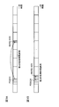
- the feedback timing of HARQ-ACK for the downlink shared channel (PDSCH) may be controlled based on the processing time (or UE capability) supported by the UE. That is, the period N1 (for example, the minimum period) from when the UE transmits the PDSCH to when the HARQ-ACK is transmitted is set differently based on the first processing time and the second processing time (FIG. 1). reference).
- FIG. 1A shows an example in which the first processing time is applied
- FIG. 1B shows an example in which the second processing time is applied.
- the UE transmits the HARQ-ACK after receiving the PDSCH when applying (or supporting) the second processing time, as compared with the case of applying the first processing time.
- the time period N1 until the operation is completed can be shortened.
- a UE having UE capability # 2 has a processing capability of completing preparation for HARQ-ACK transmission after a second processing time (N1) after receiving the PDSCH.
- the value of the second processing time is not limited to this, and may be appropriately set according to other parameters or the like.
- the transmission timing of the uplink shared channel (PUSCH) indicated by the downlink control information (DCI) may be controlled based on the processing time (or UE capability) supported by the UE. That is, the period N2 (for example, the minimum period) from when the UE receives the DCI to when the UE transmits the PUSCH is set differently based on the first processing time and the second processing time (see FIG. 2). .
- FIG. 2A shows an example in which the first processing time is applied
- FIG. 2B shows an example in which the second processing time is applied.
- the UE when the UE applies (or supports) the second processing time, the UE receives the DCI and transmits the PUSCH compared with the case of applying the first processing time.
- Period N2 can be shortened.
- a UE having UE capability # 2 has a processing capability capable of completing preparation for PUSCH transmission after a second processing time (N2) after receiving DCI.
- the value of the second processing time is not limited to this, and may be appropriately set according to other parameters or the like.
- a UE that supports the second processing time may transmit the fact to the base station as UE capability information.
- the problem is how to control it.
- communication using a plurality of processing times is not properly performed, there is a possibility that a decrease in throughput or a deterioration in communication quality may occur.
- the present inventors focus on the point that the UE notifies the base station of UE capability information (for example, UE capability # 2) as one aspect of the present embodiment, and perform the second processing based on a predetermined condition.
- the idea was to control the timing of applying time.
- the present inventors have noted that, as another aspect of the present embodiment, there are a plurality of different operations as operations for applying the processing time of the UE, and apply the first processing time and the second processing time.
- the idea is to control each action that takes place.
- first processing time or UE capability # 1
- second processing time or UE capability # 2
- the number of possible processing times is not limited to two, but may be three or more.
- the first processing time and the second processing time may be defined as the same processing time for some operations in communication (for example, UE operation).
- the first aspect controls the application timing of the second processing time corresponding to UE capability # 2 based on a predetermined condition.
- the predetermined condition for applying the second processing time is when the application of the second processing time is set (or requested) by the base station to the UE (case 1), or when the UE transmits the UE capability information to the base station. May be notified (case 2). In case 2, the base station does not need to set (or request) the application of the second processing time to the UE.
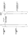
- FIG. 3 shows an example of a case where the UE controls a predetermined operation using the second processing time after at least the application of the second processing time corresponding to UE capability # 2 is set from the base station. I have.
- the UE supporting UE capability # 2 transmits the support to the base station (or network) as UE capability information (step 1A).
- the fact that UE capability # 1 is supported may be separately transmitted to the base station as UE capability information, or the UE capability information related to UE capability # 1 may not be transmitted to the base station.
- UEA UE that does not support UE capability # 2 transmits to the base station that it does not support it or that it supports UE capability # 1, or does not transmit anything to the base station as UE capability information relating to processing capability.
- the base station that has received the UE capability information (for example, UE capability # 2) from the UE sets the application of the second processing time corresponding to the UE capability # 2 to the UE (step 1B).
- UE capability information for example, UE capability # 2
- the UE transmits a message (for example, Reconf complete message) indicating that the setting (or reconfiguration) is completed to the base station based on the setting (or notification) from the base station (step 1C).
- a message for example, Reconf complete message
- the UE performs control such that the second processing time corresponding to the UE capability # 2 is applied to the predetermined operation in step 1C and thereafter.
- the UE may perform control such that the second processing time is applied to the predetermined operation after the application of the second processing time is set by the base station (for example, after step 1B).
- the base station sets the UE until the timing for setting the application of the second processing time corresponding to the UE capability # 2 to the UE (step 1B) or the timing for receiving the setting completion message from the UE (step 1C).
- the scheduling may be controlled on the assumption that the first processing time corresponding to the capability # 1 is applied. Further, the base station may control the scheduling on the assumption that the second processing time can be applied after step 1C (or step 1B).
- the UE by applying the second processing time after at least the application of the second processing time is set by the base station, the UE needs to always perform the transmission / reception processing in consideration of the second processing time. Gone. As a result, it is possible to reduce the load of the transmission / reception processing on the UE.
- the UE corresponding to the UE capability # 1 It may be assumed that the same processing time as the first processing time is applied.
- the second processing time may be set commonly for DL and UL, or may be set separately. Further, the second processing time may be set for each UE operation.
- the second processing time may be set commonly for a plurality of CCs included in a plurality of cell groups (for example, PUCCH groups) in the carrier aggregation (CA), or may be separately set for each CC. Good.
- the second processing time may be set commonly for a plurality of CCs included in a plurality of cell groups, or may be separately set for each CC.
- FIG. 4 illustrates an example of a case where the UE controls the predetermined operation using the second processing time after the UE transmits UE capability information (UE capability # 2) to the base station.
- UE capability # 2 UE capability information
- the UE supporting the UE capability # 2 transmits the support to the base station (or the network) as UE capability information (step 2A).
- the fact that UE capability # 1 is supported may be separately transmitted to the base station as UE capability information, or the UE capability information related to UE capability # 1 may not be transmitted to the base station.
- UEA UE that does not support UE capability # 2 transmits to the base station that it does not support it or that it supports UE capability # 1, or does not transmit anything to the base station as UE capability information relating to processing capability.
- the UE may perform control such that the second processing time corresponding to the UE capability # 2 is applied to the predetermined operation after step 2A.
- the UE may control the transmission / reception processing on the assumption that the base station performs scheduling for a predetermined operation based on the second processing time.
- the base station After receiving the UE capability information (UE capability # 2) from the UE (step 2A and thereafter), the base station controls the scheduling by assuming that the second processing time can be applied to the predetermined operation. Is also good.
- the second processing time based on the notification of the UE capability information (UE capability # 2) from the UE to the base station the amount of information transmitted from the base station to the UE (for example, , Steps 1B and 1C in FIG. 3) can be reduced.
- the UE may be configured to perform at least one of the operation related to the PDSCH and the operation related to the PUSCH within the second processing time corresponding to the UE capability # 2 when the predetermined condition is satisfied.
- the operation for the PDSCH may be, for example, HARQ-ACK feedback for the PDSCH.
- the operation related to the PUSCH may be, for example, PUSCH transmission based on DCI instructing UL transmission.
- the predetermined condition may be a case where at least one of the following conditions (or all conditions) is satisfied.
- -When carrier aggregation is not applied -When one numerology is applied to PDCCH, PDSCH and PUSCH in the serving cell-When PDSCH or PUSCH is based on a predetermined mapping type (for example, mapping types A and B) When allocation is controlled.
- mapping types A and B For example, mapping types A and B
- UCI is not multiplexed on PUSCH.
- C-RNTI is applied to PDCCH transmitting DCI (CRC scrambled by C-RNTI).
- the UE may assume that it is not required to apply the second processing time to the operation related to the PDSCH and the operation related to the PUSCH.
- the UE may be configured to perform at least one of the operation related to the PDSCH and the operation related to the PUSCH within the first processing time corresponding to the UE capability # 1.
- Case 1 and case 2 described above may be used in combination.
- the UE after transmitting UE capability information (UE capability # 2) to the base station, the UE applies case 1 above when the application of the second processing time is set by the base station.
- the UE after transmitting the UE capability information (UE capability # 2) to the base station, the UE applies case 2 if the base station does not set the application of the second processing time within a predetermined period. It may be.
- N1 corresponds to the processing time of the operation related to the PDSCH
- N2 corresponds to the processing time of the operation related to the PUSCH.
- the operation regarding the PDSCH may be, for example, HARQ-ACK feedback for the PDSCH.
- the operation related to the PUSCH may be, for example, PUSCH transmission based on DCI instructing UL transmission.
- the UE controls the processing time applied to the processing related to the HARQ-ACK feedback for the PDSCH or the processing related to the PUSCH transmission based on DCI indicating UL transmission is an issue.
- how to control the processing time applied to the operation other than the operation related to the PDSCH and the operation related to the PUSCH becomes a problem.
- the processing time applied by the UE will be described.
- the UE may perform processing related to HARQ-ACK feedback for PDSCH or DCI instructing UL transmission.
- the second processing time is not applied to the processing related to the PUSCH transmission based on the second processing time.
- Processing related to HARQ-ACK feedback for PDSCH or processing related to PUSCH transmission based on DCI includes application of UCI ⁇ on ⁇ PUSCH that multiplexes and transmits UCI (eg, HARQ-ACK) to PUSCH, timing advance (TA). At least one of command application and TPC command application may be used.
- the $ TA command is a command indicating the transmission timing value of the uplink channel, and is included in the MAC control element.
- the TA command may be signaled at the MAC layer from the radio base station to the user terminal.
- the TPC command indicates an increase / decrease value of UL transmission power (for example, PUSCH, PUCCH, SRS, or the like), and may be included in, for example, DCI transmitted on the PDCCH.
- the second processing time is not applied to the HARQ-ACK feedback timing and the PUSCH transmission (or PUSCH schedule) timing.
- the UE may apply the same time as the first processing time (or a time longer than the first processing time) to the HARQ-ACK feedback timing and the PUSCH transmission (or PUSCH schedule) timing.
- the UE may also control the application of the TA command based on the first processing time. Similarly, the UE may control the application of the TPC command based on the first processing time.
- the second processing time is used to improve the communication throughput, while the transmission condition uses the first processing time to use the processing load of the UE. Increase can be suppressed.
- the network controls scheduling and the like in consideration of UE capability information (UE capability # 2) reported from the UE. For example, when the UCI is transmitted without being multiplexed on the PUSCH, the base station transmits HARQ-ACK for the PDSCH based on the second processing time of the UE capability # 2, and transmission timing of the PUSCH based on the UL grant. Control. In other cases (eg, using UCI @ on @ PUSCH), the base station transmits HARQ-ACK to PDSCH based on the first processing time of UE capability # 1, and transmits PUSCH based on UL grant. The transmission timing may be controlled.
- UE capability # 2 UE capability information
- the base station performs the same timing (for example, the timing based on the first processing time) for at least one of the TA command and the TPC command. ) May be applied.
- the UE has a processing time (eg, a second processing time) in which at least one (or all) of the HARQ-ACK transmission using the PUSCH, the application of the TA command, and the application of the TPC command is shorter than the first processing time. It is not necessary to assume to apply.
- a processing time eg, a second processing time
- the second processing time is applied to HARQ-ACK feedback timing and PUSCH transmission (or PUSCH schedule) timing.
- HARQ-ACK is multiplexed and transmitted to the PUSCH based on the second processing time (N1, N2) corresponding to UE capability # 2.
- the UE does not assume that HARQ-ACK is multiplexed on the PUSCH based on the second processing time (N1, N2) corresponding to UE capability # 2.
- the UE may multiplex and transmit the HARQ-ACK to the PUSCH based on the first processing time corresponding to the UE capability # 1.
- the UE for example, case 2 above
- the UE for example, case 2 above
- the UE for example, case 2 above
- the UE for example, case 2 above
- At least the UE for which the second processing time corresponding to the UE capability # 2 is set for the UL transmits at least one of the TA command and the TPC command based on the UE capability # 2 (the second processing time). May be applied.
- the UE for which the second processing time is set is controlled such that at least one of the application timing of the TA command and the application timing of the TPC command is shorter than the UE for which the second processing time is not set. May be.
- the base station notifies the process from the base station. Communication conditions can be quickly reflected, so that communication quality can be improved.
- a UE having UE capability # 2 may be configured to perform at least one (or all) of SS block detection, a random access procedure (eg, PRACH transmission, etc.), system information (eg, SIB), and paging process.
- the processing time of 2 is not applied.
- the UE may apply the first processing time to these processes.
- a common processing time for example, the first processing time
- all UEs for processing (or signals and channels) used for initial connection and the like suppresses an increase in processing load. be able to.
- the UE capability (or processing time) is switched and applied.
- the second processing time is applied to a predetermined operation and apply the first processing time other than the predetermined operation. Also, depending on the communication environment or the timing of setting the second processing time for the UE, for the same operation, the first processing time is applied in the first period, and the second processing time is set in the second period. It is also conceivable to apply.
- the UE may be configured to switch between the UE capability # 1 (or the first processing time) and the UE capability # 2 (or the second processing time). For example, the UE dynamically sets the first processing time and the second processing time for a process (or signal, channel) having the same TTI length or the same transmission characteristic in a predetermined cell (CC or BWP). Switch to and apply.
- the process having the same transmission characteristics may be a process in which at least one of the mapping type of the demodulation reference signal (for example, DMRS) and the transport block size (TBS) are the same.
- a predetermined RNTI when a predetermined RNTI is set (or when a downlink control channel (or DCI) to which a predetermined RTNI is applied is received), the UE has UE capability # 1 (or a first processing time). And UE capability # 2 (or second processing time).
- UE capability # 1 or a first processing time
- UE capability # 2 or second processing time
- the UE responds to the reception of the DCI (or DCI format) to which the RNTI is applied, Control may be performed to apply UE capability # 2 (or the second processing time).
- the predetermined RNTI may be, for example, an RNTI used for a DCI (PDCCH) for selecting a modulation and coding scheme (MCS) table.
- the predetermined RNTI may be an RNTI used for DCI instructing an operation for low delay and high reliability (for example, URLLC).
- the UE may be configured such that, when a predetermined RNTI is not set, a UE capability (UE capability # 1 or UE capability # 2) to be applied is determined by quasi-static (for example, an upper layer such as RRC signaling). Good.
- a UE capability UE capability # 1 or UE capability # 2 to be applied is determined by quasi-static (for example, an upper layer such as RRC signaling). Good.
- the UE when receiving the DCI transmitted in the common search space (CSS: Common Search Space), the UE applies a predetermined UE capability (for example, UE capability # 1 (or first processing time)). Is also good. By this means, the same processing time is applied between UEs as in the existing system, for DCI that is commonly transmitted to UEs, so that it is possible to suppress processing complexity.
- a predetermined UE capability for example, UE capability # 1 (or first processing time)
- the UE corresponds to the UE capability # 2 for at least one of the operation related to the PDSCH and the operation related to the PUSCH. Control may be performed within the processing time of 2.
- a predetermined time period for example, a slot
- the UE determines a UE capability (or processing time) to be applied. You may switch. For example, when DCI is detected in four or more symbols of a slot, UE capability # 1 (for example, first processing time) may be switched to UE capability # 2 (for example, second processing time).
- UE capability # 1 for example, first processing time
- UE capability # 2 for example, second processing time
- the UE capability (or processing time) can be dynamically and flexibly switched according to the time period for transmitting and receiving DCI. Therefore, when the data size is large, UE capability # 1 (for example, first processing time) ) Can be controlled, and if low delay is required, the DCI time period that switches to UE capability # 2 (for example, the second processing time) can be used.
- the UE is configured to apply the UE capability # 2 (for example, the second processing time) in a specific situation (switch from the first processing time to the second processing time), and in other situations, the UE is configured to use the UE capability # 2.
- a configuration may be adopted in which the capability # 1 (for example, the first processing time) is applied.
- ⁇ Skip control> When the UE switches from the UE capability # 1 (for example, the first processing time) to the UE capability # 2 (for example, the second processing time) for the predetermined operation, the UE performs the predetermined operation for applying the UE capability # 1. At least a part (for example, operation for a predetermined period) may be controlled to be skipped.
- skip control when the predetermined operation is an operation related to PDSCH (PDSCH processing) and when the predetermined operation is an operation related to PUSCH (PUSCH processing / transmission) will be described.
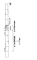
- FIG. 5 shows an example of switching from UE capability # 1 (for example, first processing time) to UE capability # 2 (for example, second processing time) in slot n. That is, the UE applies the second processing time to HARQ-ACK feedback for the PDSCH received in slot n. For example, the UE transmits HARQ-ACK for the PDSCH received in slot n in a slot (slot n or slot n + 1) corresponding to a predetermined symbol (eg, three symbols).
- a predetermined symbol eg, three symbols
- the UE may skip operations related to the PDSCH for a predetermined period (for example, decoding of a transport block (TB), etc.) among operations related to the PDSCH to which the UE capability # 1 is applied.
- the predetermined period may be, for example, at least a part (or all) of the slot nWDL to the slot n-1. Note that the predetermined period is not limited to this, and may be a period specified in symbol units or subframe units.
- the W DL may be, for example, a value determined from a UE capability having a value in a range from 0 to k ⁇ 1. Note that k corresponds to the DL HARQ process time. Further, WDL may be a value set from the base station to the UE.
- FIG. 5 shows a case where the WDL is 4 as an example.
- the timing of transmitting HARQ-ACK for the PDSCH received in slot n-W DL may be slot n.
- the timing of transmitting the HARQ-ACK for the PDSCH received from slot n-W DL +1 to slot n-1 may be after slot n. That is, the UE needs to perform HARQ-ACK transmission processing for the PDSCH received before slot n-1 in slot n.
- the HARQ-ACK may be transmitted in slot n or slot n + 1. Therefore, by skipping an operation (for example, decoding of a TB, etc.) related to the PDSCH for a predetermined period in which the first processing time is applied, the HARQ-ACK in which the processing load on the UE is reduced and the second processing time is applied is appropriately performed Can be done. In addition, it is possible to suppress a collision between the transmission timing of the HARQ-ACK to which the first processing time is applied and the transmission timing of the HARQ-ACK to which the second processing time is applied.
- the UE may autonomously determine whether the skip operation is applied to the predetermined period or the period in which the skip operation is applied.
- skipping the operation related to the PDSCH for example, skipping the decoding of the TB
- the UE indicates that the TB could not be decoded (the decoding of the TB failed) from the physical layer (physical layer) to the upper layer (higher layer). You may be notified.
- whether or not a skip operation is applied for a predetermined period, or a period during which the skip operation is applied may be set from the base station to the UE, or may be determined in advance by specifications.
- the UE may perform control such that the number of PDSCHs to be skipped is reduced as much as possible in consideration of, for example, a period in which the second processing time is applied. Further, when skipping the operation related to the PDSCH for a predetermined period to which the UE capability # 1 is applied, the UE may skip the operation in all CCs. As a result, the processing load on the UE can be reduced as much as possible, so that the operation using the UE capability # 2 can be appropriately performed. Note that some CCs (for example, PCell, PSCell) and the like may not be skipped.
- the UE when the UE skips the operation related to the PDSCH for a predetermined period in which the UE capability # 1 is applied, the UE may skip the operation in the predetermined CC (for example, the CC in which the UE capability # 2 is applied). Thereby, communication can be performed without affecting operations of other CCs.
- the predetermined CC for example, the CC in which the UE capability # 2 is applied.
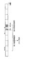
- FIG. 6 shows an example of switching from UE capability # 1 (for example, first processing time) to UE capability # 2 (for example, second processing time) in slot n. That is, the UE applies the second processing time to the PUSCH transmission based on the DCI received in slot n. For example, the UE transmits a PUSCH based on DCI received in slot n in a slot (slot n or slot n + 1) corresponding to a predetermined symbol (for example, 5 symbols).
- UE capability # 1 for example, first processing time
- UE capability # 2 for example, second processing time
- the UE applies the second processing time to the PUSCH transmission based on the DCI received in slot n.
- the UE transmits a PUSCH based on DCI received in slot n in a slot (slot n or slot n + 1) corresponding to a predetermined symbol (for example, 5 symbols).
- the UE may skip the operation related to the PUSCH for a predetermined period (for example, the monitoring of the DCI or the PDCCH corresponding to the predetermined DCI format) among the operations related to the PUSCH to which the UE capability # 1 is applied.
- the predetermined period may be, for example, at least a part (or all) of the slot nW UL to the slot n-1. Note that the predetermined period is not limited to this, and may be a period specified in symbol units or subframe units.
- W UL may be, for example, a value determined from UE capability having a value in the range of 0 to k ⁇ 1. Note that k corresponds to the UL scheduling time. WUL may be a value set by the base station to the UE.
- FIG. 6 shows a case where W UL is 4 as an example.
- the transmission timing of the PUSCH based on the DCI received in slot n-W UL may be slot n.
- the PUSCH transmission timing based on the DCI received from slot n ⁇ W UL +1 to slot n ⁇ 1 may be after slot n. That is, the UE needs to perform a PUSCH transmission process based on the DCI received before slot n-1 in slot n.
- the PUSCH when the second processing time is applied to the PUSCH transmission based on the DCI received in the slot n, the PUSCH may be transmitted in the slot n or the slot n + 1. Therefore, by skipping the operation (for example, decoding of a TB, etc.) related to the PUSCH in the predetermined period in which the first processing time is applied, the processing load on the UE is reduced, and the PUSCH in which the second processing time is applied is appropriately performed. be able to. Further, it is possible to suppress a collision between the transmission timing of the PUSCH to which the first processing time is applied and the transmission timing of the PUSCH to which the second processing time is applied.
- the operation for example, decoding of a TB, etc.
- the UE may autonomously determine whether the skip operation is applied to the predetermined period or the period in which the skip operation is applied.
- the UE requests data from an upper layer based on the issued PUSCH transmission instruction (PUSCH grant). Is also good. For example, the same processing as that performed at the time of skipping in a LAA base to which listening is applied before transmission may be performed.
- whether or not a skip operation is applied for a predetermined period from the base station to the UE, or a period in which the skip operation is applied may be set, or may be predetermined in the specification.
- the UE may control so as to reduce the number of skipped PUSCHs as much as possible in consideration of a period in which the second processing time is applied. Further, when skipping the operation related to the PUSCH for a predetermined period to which the UE capability # 1 is applied, the UE may skip the operation in all CCs. As a result, the processing load on the UE can be reduced as much as possible, so that the operation using the UE capability # 2 can be appropriately performed. Note that some CCs (for example, PCell, PSCell) and the like may not be skipped.
- the UE when the UE skips the operation related to the PUSCH for a predetermined period in which the UE capability # 1 is applied, the UE may skip the operation in the predetermined CC (for example, the CC in which the UE capability # 2 is applied). Thereby, communication can be performed without affecting operations of other CCs.
- the predetermined CC for example, the CC in which the UE capability # 2 is applied.
- the UE When CA is applied, the UE bases on at least one of UE capability # 2 (for example, second processing time) support, UL support, and DL support for each subcarrier interval (SCS). Send to the station.
- UE capability # 2 for example, second processing time
- UL support for example, UL support
- DL support for each subcarrier interval (SCS).
- the UE may transmit a CA configuration in which UE capability (eg, UE capability # 2) can be set.
- the CA configuration may be a combination of CA bands in which UE capability can be set, a maximum number of CCs, a combination of subcarrier intervals in a plurality of CCs, a maximum number of bits of a transport block in a slot or a 1 ms in a plurality of CCs.
- the CC may be a CC to which all frame configuration types can be applied.
- the UE capability # 2 when UE capability # 2 is set in any of the secondary cells included in the PUCCH group, the UE capability # 2 may be set for a cell that transmits the PUCCH (PUCCH cell, also referred to as PUCCH @ SCell). Good.
- the UE capability # 2 can be applied to the HARQ-ACK feedback for the PDSCH received on the predetermined SCell, and the HARQ-ACK feedback can be transmitted on the PUCCH cell.
- the PUCCH group is a group including a plurality of cells including a secondary cell associated with a cell (PCell or PUCCH SCell) that transmits a PUCCH.
- a secondary cell associated with a cell PCell or PUCCH SCell
- the UCI of the secondary cell associated with PUCCH @ SCell is multiplexed and transmitted on the PUCCH of PUCCH @ SCell.
- the UE capability # 2 when UE capability # 2 is set in any of the secondary cells included in the PUCCH group, the UE capability # 2 may not necessarily be set in the cell that transmits the PUCCH. If UE capability # 2 is not set in the PUCCH cell, the UE capability # 2 may be applied to the HARQ-ACK feedback for the PDSCH received in a predetermined SCell and transmitted in the PUCCH cell. Alternatively, when UE capability # 2 is not set in the PUCCH cell, the UE capability # 2 may not be applied to HARQ-ACK feedback for the PDSCH received by a predetermined SCell.
- UE capability # 2 may be set to a cell that performs only DL and a cell that performs only UL (also referred to as a SUL (Supplemental UpLink) cell).
- the configuration may be such that cross-carrier scheduling is not supported.
- scheduling can be controlled in consideration of UE capability # 1 (for example, the first processing time), so that complication of processing can be suppressed.
- cross-carrier scheduling may be supported.
- a configuration in which cross carrier scheduling is applied in the same PUCCH group may be adopted.
- UE capability # 2 When cross-carrier scheduling is supported when UE capability # 2 is applied, UE capability # 2 is set for both the scheduling cell (cell in which DCI is transmitted) and the cell to be scheduled (cell in which PDSCH is transmitted).
- the configuration may be set.
- the UE capability # 1 may be set for one cell and the UE capability # 2 may be set for the other cell.
- the UE reports the maximum number of CSI processes for each reporting mode (eg, type 1, 2 etc.) as UE capability information.
- UE capability # 2 for example, the second processing time
- the maximum number of CSI processes may be changed. Therefore, when applying UE capability # 2, the UE (or base station) may update (update) the maximum number of CSI processes based on the UE capability # 2.
- a parameter whose condition is changed by application of UE capability # 2 may be appropriately updated according to application of UE capability # 2.
- the UE when the UE reports a predetermined UE capability, the UE may be configured to allow simultaneous transmission using different TTI lengths over different carriers.
- the simultaneous transmission may be configured to be allowed only in the cell group or the PUCCH cell group.
- Wireless communication system Hereinafter, the configuration of the wireless communication system according to the present embodiment will be described.
- communication is performed using at least one combination of the above-described plurality of aspects.
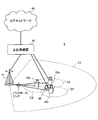
- FIG. 7 is a diagram showing an example of a schematic configuration of the wireless communication system according to the present embodiment.
- carrier aggregation (CA) and / or dual connectivity (DC) in which a plurality of basic frequency blocks (component carriers) each having a system bandwidth (for example, 20 MHz) of the LTE system as one unit are applied. can do.
- DC dual connectivity
- the wireless communication system 1 includes LTE (Long Term Evolution), LTE-A (LTE-Advanced), LTE-B (LTE-Beyond), SUPER 3G, IMT-Advanced, 4G (4th generation mobile communication system), and 5G. (5th generation mobile communication system), NR (New Radio), FRA (Future Radio Access), New-RAT (Radio Access Technology), etc., or a system for realizing these.
- LTE Long Term Evolution
- LTE-A LTE-Advanced
- LTE-B LTE-Beyond
- SUPER 3G IMT-Advanced
- 4G 4th generation mobile communication system
- 5G 5th generation mobile communication system
- NR New Radio
- FRA Full Radio Access
- New-RAT Radio Access Technology
- the radio communication system 1 includes a radio base station 11 forming a macro cell C1 having a relatively wide coverage, and a radio base station 12 (12a-12c) arranged in the macro cell C1 and forming a small cell C2 smaller than the macro cell C1. , Is provided. Further, user terminals 20 are arranged in the macro cell C1 and each small cell C2. The arrangement, number, and the like of each cell and the user terminals 20 are not limited to the modes shown in the figure.
- the user terminal 20 can be connected to both the radio base station 11 and the radio base station 12. It is assumed that the user terminal 20 uses the macro cell C1 and the small cell C2 simultaneously using CA or DC. Also, the user terminal 20 may apply CA or DC using a plurality of cells (CCs) (for example, five or less CCs, six or more CCs).
- CCs cells
- Communication between the user terminal 20 and the radio base station 11 can be performed using a carrier having a relatively low frequency band (for example, 2 GHz) and a narrow bandwidth (also referred to as an existing carrier or a legacy carrier).
- a carrier having a relatively high frequency band for example, 3.5 GHz, 5 GHz or the like
- the same carrier as that between may be used.
- the configuration of the frequency band used by each wireless base station is not limited to this.
- the user terminal 20 can perform communication using time division duplex (TDD: Time Division Duplex) and / or frequency division duplex (FDD: Frequency Division Duplex) in each cell.
- TDD Time Division Duplex
- FDD Frequency Division Duplex
- a single numerology may be applied, or a plurality of different numerologies may be applied.
- Numerology may be a communication parameter applied to transmission and / or reception of a certain signal and / or channel, for example, subcarrier interval, bandwidth, symbol length, cyclic prefix length, subframe length. , TTI length, number of symbols per TTI, radio frame configuration, filtering process, windowing process, and the like.
- the wireless base station 11 and the wireless base station 12 are connected by wire (for example, an optical fiber compliant with CPRI (Common Public Radio Interface), an X2 interface, or the like) or wirelessly. May be done.
- the wireless base station 11 and each wireless base station 12 are connected to the upper station device 30 and connected to the core network 40 via the upper station device 30.
- the higher station apparatus 30 includes, for example, an access gateway apparatus, a radio network controller (RNC), and a mobility management entity (MME), but is not limited thereto.
- RNC radio network controller
- MME mobility management entity
- each wireless base station 12 may be connected to the higher station apparatus 30 via the wireless base station 11.
- the radio base station 11 is a radio base station having relatively wide coverage, and may be called a macro base station, an aggregation node, an eNB (eNodeB), a transmission / reception point, or the like.
- the radio base station 12 is a radio base station having local coverage, and includes a small base station, a micro base station, a pico base station, a femto base station, a HeNB (Home eNodeB), an RRH (Remote Radio Head), and transmission / reception. It may be called a point or the like.
- the wireless base stations 11 and 12 are not distinguished, they are collectively referred to as a wireless base station 10.
- Each user terminal 20 is a terminal corresponding to various communication systems such as LTE and LTE-A, and may include not only mobile communication terminals (mobile stations) but also fixed communication terminals (fixed stations).
- Orthogonal Frequency Division Multiple Access (OFDMA) is applied to the downlink as a wireless access scheme, and Single-Carrier Frequency Division Multiple Access (SC-FDMA: Single Carrier) is applied to the uplink. Frequency Division Multiple Access) and / or OFDMA is applied.
- OFDMA Orthogonal Frequency Division Multiple Access
- SC-FDMA Single Carrier Frequency Division Multiple Access
- OFDMA is a multicarrier transmission scheme in which a frequency band is divided into a plurality of narrow frequency bands (subcarriers), and data is mapped to each subcarrier to perform communication.
- SC-FDMA divides a system bandwidth into bands each composed of one or a continuous resource block for each terminal, and a single carrier transmission that reduces interference between terminals by using different bands for a plurality of terminals. It is a method.
- the uplink and downlink radio access schemes are not limited to these combinations, and other radio access schemes may be used.
- a downlink shared channel (PDSCH: Physical Downlink Shared Channel), a broadcast channel (PBCH: Physical Broadcast Channel), a downlink L1 / L2 control channel, and the like shared by each user terminal 20 are used. Used.
- the PDSCH transmits user data, upper layer control information, SIB (System Information Block), and the like.
- SIB System Information Block
- MIB Master ⁇ Information ⁇ Block
- Downlink L1 / L2 control channels are downlink control channels (PDCCH (Physical Downlink Control Channel) and / or EPDCCH (Enhanced Physical Downlink Control Channel)), PCFICH (Physical Control Format Indicator Channel), and PHICH (Physical Hybrid-ARQ Indicator Channel).
- PDCH Physical Downlink Control Channel
- EPDCCH Enhanced Physical Downlink Control Channel
- PCFICH Physical Control Format Indicator Channel
- PHICH Physical Hybrid-ARQ Indicator Channel
- DCI Downlink Control Information
- DCI Downlink Control Information
- the scheduling information may be notified by DCI.
- a DCI that schedules DL data reception may be called a DL assignment
- a DCI that schedules UL data transmission may be called an UL grant.
- PCFICH transmits the number of OFDM symbols used for PDCCH.
- the PHICH transmits acknowledgment information (for example, retransmission control information, HARQ-ACK, ACK / NACK, etc.) of HARQ (Hybrid Automatic Repeat Repeat request) for the PUSCH.
- the EPDCCH is frequency-division multiplexed with a PDSCH (Downlink Shared Data Channel) and used for transmission of DCI and the like like the PDCCH.
- PDSCH Downlink Shared Data Channel
- an uplink shared channel (PUSCH: Physical Uplink Shared Channel), an uplink control channel (PUCCH: Physical Uplink Control Channel), a random access channel (PRACH: Physical Random Access Channel) or the like is used.
- PUSCH Physical Uplink Shared Channel
- PUCCH Physical Uplink Control Channel
- PRACH Physical Random Access Channel
- user data higher layer control information, etc. are transmitted.
- downlink radio link quality information CQI: Channel Quality Indicator
- delivery confirmation information delivery confirmation information
- scheduling request (SR: Scheduling Request), and the like are transmitted by PUCCH.
- the PRACH transmits a random access preamble for establishing a connection with a cell.
- a cell-specific reference signal CRS: Cell-specific Reference Signal
- CSI-RS Channel State Information-Reference Signal
- DMRS Demodulation Reference Signal
- PRS Positioning Reference Signal
- a measurement reference signal SRS: Sounding Reference Signal
- DMRS demodulation reference signal
- PRS Positioning Reference Signal
- the transmitted reference signal is not limited to these.
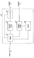
- FIG. 8 is a diagram showing an example of the overall configuration of the radio base station according to the present embodiment.
- the wireless base station 10 includes a plurality of transmitting / receiving antennas 101, an amplifier unit 102, a transmitting / receiving unit 103, a baseband signal processing unit 104, a call processing unit 105, and a transmission path interface 106.
- the transmitting / receiving antenna 101, the amplifier unit 102, and the transmitting / receiving unit 103 may be configured to include at least one each.
- the baseband signal processing unit 104 regarding user data, processing of a PDCP (Packet Data Convergence Protocol) layer, division / combination of user data, transmission processing of an RLC layer such as RLC (Radio Link Control) retransmission control, and MAC (Medium Access) Control)
- the transmission / reception unit performs retransmission control (for example, HARQ transmission processing), scheduling, transmission format selection, channel coding, inverse fast Fourier transform (IFFT) processing, precoding processing, and so on.
- HARQ transmission processing for example, HARQ transmission processing
- IFFT inverse fast Fourier transform
- precoding processing precoding processing
- the downlink control signal is also subjected to transmission processing such as channel coding and inverse fast Fourier transform, and transferred to the transmission / reception unit 103.
- the transmission / reception section 103 converts the baseband signal output from the baseband signal processing section 104 after precoding for each antenna into a radio frequency band, and transmits the radio frequency band.
- the radio frequency signal frequency-converted by the transmitting / receiving section 103 is amplified by the amplifier section 102 and transmitted from the transmitting / receiving antenna 101.
- the transmission / reception unit 103 can be configured from a transmitter / receiver, a transmission / reception circuit, or a transmission / reception device described based on common recognition in the technical field according to the present disclosure. Note that the transmission / reception unit 103 may be configured as an integrated transmission / reception unit, or may be configured from a transmission unit and a reception unit.
- a radio frequency signal received by the transmission / reception antenna 101 is amplified by the amplifier unit 102.
- the transmitting / receiving section 103 receives the upstream signal amplified by the amplifier section 102.
- Transmitting / receiving section 103 frequency-converts the received signal into a baseband signal and outputs the baseband signal to baseband signal processing section 104.
- fast Fourier transform FFT: Fast Fourier Transform
- IDFT inverse discrete Fourier transform
- error correction is performed on user data included in the input uplink signal.
- Decoding, reception processing of MAC retransmission control, reception processing of the RLC layer and PDCP layer are performed, and the data is transferred to the upper station apparatus 30 via the transmission path interface 106.
- the call processing unit 105 performs call processing (setting, release, etc.) of a communication channel, state management of the wireless base station 10, management of wireless resources, and the like.
- the transmission path interface 106 transmits and receives signals to and from the higher-level station device 30 via a predetermined interface.
- the transmission path interface 106 transmits and receives signals (backhaul signaling) to and from another wireless base station 10 via an interface between base stations (for example, an optical fiber compliant with CPRI (Common Public Radio Interface), an X2 interface). You may.
- CPRI Common Public Radio Interface
- X2 interface X2 interface
- the transmission / reception unit 103 may further include an analog beamforming unit that performs analog beamforming.
- the analog beamforming unit includes an analog beamforming circuit (for example, a phase shifter, a phase shift circuit) or an analog beamforming device (for example, a phase shifter) described based on common recognition in the technical field according to the present invention. can do.
- the transmitting / receiving antenna 101 can be constituted by, for example, an array antenna.
- the transmission / reception unit 103 is configured to be able to apply single BF and multi BF.
- Transceiving section 103 may transmit a signal using a transmission beam or may receive a signal using a reception beam.
- the transmission / reception unit 103 may transmit and / or receive a signal using a predetermined beam determined by the control unit 301.
- the transmitting / receiving section 103 transmits a downlink (DL) signal (including at least one of a DL data signal (downlink shared channel), a DL control signal (downlink control channel), and a DL reference signal) to the user terminal 20.
- DL downlink
- UL uplink
- the transmission / reception unit 103 receives UE capability information (for example, UE capability # 2) indicating that the second operation time shorter than the first processing time is supported for the predetermined operation. Further, when receiving the information on UE capability # 2, transmitting / receiving section 103 may transmit information for setting a second processing time corresponding to the UE capability # 2. Further, the transmission / reception unit 103 may receive a (re) configuration complete message (Reconf @ complete @ message).
- UE capability information for example, UE capability # 2
- transmitting / receiving section 103 may transmit information for setting a second processing time corresponding to the UE capability # 2.
- the transmission / reception unit 103 may receive a (re) configuration complete message (Reconf @ complete @ message).
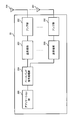
- FIG. 9 is a diagram showing an example of a functional configuration of the radio base station according to the present embodiment.
- functional blocks of characteristic portions in the present embodiment are mainly shown, and it may be assumed that wireless base station 10 also has other functional blocks necessary for wireless communication.
- the baseband signal processing unit 104 includes at least a control unit (scheduler) 301, a transmission signal generation unit 302, a mapping unit 303, a reception signal processing unit 304, and a measurement unit 305. Note that these configurations may be included in the radio base station 10, and some or all of the configurations need not be included in the baseband signal processing unit 104.
- the control unit (scheduler) 301 controls the entire wireless base station 10.
- the control unit 301 can be configured from a controller, a control circuit, or a control device described based on common recognition in the technical field according to the present disclosure.
- the control unit 301 controls, for example, signal generation in the transmission signal generation unit 302, signal assignment in the mapping unit 303, and the like. Further, the control unit 301 controls a signal reception process in the reception signal processing unit 304, a signal measurement in the measurement unit 305, and the like.
- the control unit 301 performs scheduling (for example, resources) of system information, a downlink data signal (for example, a signal transmitted on the PDSCH), and a downlink control signal (for example, a signal transmitted on the PDCCH and / or the EPDCCH; acknowledgment information and the like). Allocation). Further, control section 301 controls generation of a downlink control signal, a downlink data signal, and the like based on a result of determining whether or not retransmission control is required for an uplink data signal.
- scheduling for example, resources
- a downlink data signal for example, a signal transmitted on the PDSCH
- a downlink control signal for example, a signal transmitted on the PDCCH and / or the EPDCCH; acknowledgment information and the like. Allocation.
- control section 301 controls generation of a downlink control signal, a downlink data signal, and the like based on a result of determining whether or not retransmission control is required for an uplink data signal.
- the control unit 301 may control scheduling in consideration of a second processing time corresponding to UE capability # 2.
- Transmission signal generation section 302 generates a downlink signal (downlink control signal, downlink data signal, downlink reference signal, etc.) based on an instruction from control section 301, and outputs the generated downlink signal to mapping section 303.
- the transmission signal generation unit 302 can be configured from a signal generator, a signal generation circuit, or a signal generation device described based on common recognition in the technical field according to the present disclosure.
- the transmission signal generation unit 302 generates a DL assignment for notifying downlink data allocation information and / or a UL grant for notifying uplink data allocation information, based on an instruction from the control unit 301, for example.
- the DL assignment and the UL grant are both DCI and follow the DCI format.
- the downlink data signal is subjected to an encoding process, a modulation process, and the like according to an encoding rate, a modulation method, and the like determined based on channel state information (CSI: Channel ⁇ State ⁇ Information) from each user terminal 20 or the like.
- CSI Channel ⁇ State ⁇ Information
- Mapping section 303 maps the downlink signal generated by transmission signal generating section 302 to a predetermined radio resource based on an instruction from control section 301, and outputs it to transmitting / receiving section 103.
- the mapping unit 303 can be configured from a mapper, a mapping circuit, or a mapping device described based on common recognition in the technical field according to the present disclosure.
- the reception signal processing unit 304 performs reception processing (for example, demapping, demodulation, decoding, and the like) on the reception signal input from the transmission / reception unit 103.
- the received signal is, for example, an uplink signal (uplink control signal, uplink data signal, uplink reference signal, etc.) transmitted from the user terminal 20.
- the reception signal processing unit 304 can be configured from a signal processor, a signal processing circuit, or a signal processing device described based on common recognition in the technical field according to the present disclosure.
- the reception signal processing unit 304 outputs the information decoded by the reception processing to the control unit 301. For example, when a PUCCH including HARQ-ACK is received, HARQ-ACK is output to control section 301. Further, the reception signal processing unit 304 outputs the reception signal and / or the signal after the reception processing to the measurement unit 305.
- the measurement unit 305 performs measurement on the received signal.
- the measurement unit 305 can be configured from a measurement device, a measurement circuit, or a measurement device described based on common recognition in the technical field according to the present disclosure.
- the measurement unit 305 may perform RRM (Radio Resource Management) measurement, CSI (Channel State Information) measurement, or the like based on the received signal.
- the measurement unit 305 is configured to receive power (for example, RSRP (Reference Signal Received Power)), reception quality (for example, RSRQ (Reference Signal Received Quality), SINR (Signal to Interference plus Noise Ratio, SNR (Signal to Noise Ratio)). , Signal strength (for example, RSSI (Received @ Signal @ Strength @ Indicator)), channel information (for example, CSI), and the like.
- the measurement result may be output to the control unit 301.
- FIG. 10 is a diagram showing an example of the overall configuration of the user terminal according to the present embodiment.
- the user terminal 20 includes a plurality of transmitting / receiving antennas 201, an amplifier unit 202, a transmitting / receiving unit 203, a baseband signal processing unit 204, and an application unit 205.
- the transmitting / receiving antenna 201, the amplifier unit 202, and the transmitting / receiving unit 203 may be configured to include at least one each.
- the radio frequency signal received by the transmitting / receiving antenna 201 is amplified by the amplifier unit 202.
- the transmission / reception unit 203 receives the downlink signal amplified by the amplifier unit 202.
- the transmission / reception section 203 converts the frequency of the received signal into a baseband signal, and outputs the baseband signal to the baseband signal processing section 204.
- the transmission / reception unit 203 can be configured from a transmitter / receiver, a transmission / reception circuit, or a transmission / reception device described based on common recognition in the technical field according to the present disclosure. Note that the transmission / reception unit 203 may be configured as an integrated transmission / reception unit, or may be configured from a transmission unit and a reception unit.
- the baseband signal processing unit 204 performs FFT processing, error correction decoding, reception processing for retransmission control, and the like on the input baseband signal.
- the downlink user data is transferred to the application unit 205.
- the application unit 205 performs processing related to layers higher than the physical layer and the MAC layer. Also, of the downlink data, broadcast information may be transferred to the application unit 205.
- uplink user data is input from the application unit 205 to the baseband signal processing unit 204.
- the baseband signal processing unit 204 performs retransmission control transmission processing (eg, HARQ transmission processing), channel coding, precoding, discrete Fourier transform (DFT) processing, IFFT processing, and the like, and performs transmission / reception processing. Transferred to 203.
- the transmission / reception unit 203 converts the baseband signal output from the baseband signal processing unit 204 into a radio frequency band and transmits the radio frequency band.
- the radio frequency signal frequency-converted by the transmitting / receiving section 203 is amplified by the amplifier section 202 and transmitted from the transmitting / receiving antenna 201.
- the transmission / reception unit 203 may further include an analog beamforming unit that performs analog beamforming.
- the analog beamforming unit includes an analog beamforming circuit (for example, a phase shifter, a phase shift circuit) or an analog beamforming device (for example, a phase shifter) described based on common recognition in the technical field according to the present invention. can do.
- the transmitting / receiving antenna 201 can be constituted by, for example, an array antenna.
- the transmission / reception unit 203 is configured so that a single BF and a multi BF can be applied.
- the transmission / reception unit 203 may transmit a signal using a transmission beam or may receive a signal using a reception beam.
- the transmission / reception unit 203 may transmit and / or receive a signal using a predetermined beam determined by the control unit 401.
- the transmitting / receiving section 203 receives a downlink (DL) signal (including at least one of a DL data signal (downlink shared channel), a DL control signal (downlink control channel), and a DL reference signal) from the radio base station 10,
- DL downlink
- DL control signal downlink control channel
- UL uplink
- the transmission / reception unit 203 transmits UE capability information (for example, UE capability # 2) indicating that the second operation time shorter than the first processing time is supported for the predetermined operation.
- UE capability information for example, UE capability # 2
- the transmission / reception unit 203 may receive the setting information of the second processing time corresponding to the UE capability # 2.
- the transmission / reception unit 203 may transmit a (re) configuration complete message (Reconf ⁇ complete ⁇ message).
- FIG. 11 is a diagram showing an example of a functional configuration of the user terminal according to the present embodiment. Note that, in this example, functional blocks of characteristic portions in the present embodiment are mainly shown, and it may be assumed that the user terminal 20 also has other functional blocks necessary for wireless communication.
- the baseband signal processing unit 204 of the user terminal 20 includes at least a control unit 401, a transmission signal generation unit 402, a mapping unit 403, a reception signal processing unit 404, and a measurement unit 405. Note that these configurations need only be included in the user terminal 20, and some or all of the configurations need not be included in the baseband signal processing unit 204.
- the control unit 401 controls the entire user terminal 20.
- the control unit 401 can be configured by a controller, a control circuit, or a control device described based on common recognition in the technical field according to the present disclosure.
- the control unit 401 controls, for example, signal generation in the transmission signal generation unit 402, signal assignment in the mapping unit 403, and the like. Further, the control unit 401 controls signal reception processing in the reception signal processing unit 404, signal measurement in the measurement unit 405, and the like.
- the control unit 401 acquires the downlink control signal and the downlink data signal transmitted from the radio base station 10 from the reception signal processing unit 404.
- the control unit 401 controls generation of an uplink control signal and / or an uplink data signal based on a result of determining whether or not retransmission control is required for a downlink control signal and / or a downlink data signal.
- the control unit 401 controls the second processing time to be applied to the predetermined operation after the UE capability information is transmitted or after the application of the second processing time is set.
- the control unit 401 may apply the first processing time to an operation other than the predetermined operation even when the application of the second processing time is set.
- the control unit 401 may switch between the first processing time and the second processing time based on the downlink control information.
- control unit 401 when switching the processing time applied to the predetermined operation from the first processing time to the second processing time, the control unit 401 skips the predetermined operation applying the first processing time in the predetermined period. May be controlled.
- control unit 401 may separately report the application of the second processing time for each cell or each predetermined cell group. That is, when communication is performed using a plurality of cells, the application of the second processing time may be separately set for each cell or each predetermined cell group.
- Transmission signal generating section 402 generates an uplink signal (uplink control signal, uplink data signal, uplink reference signal, etc.) based on an instruction from control section 401 and outputs the generated signal to mapping section 403.
- the transmission signal generation unit 402 can be configured from a signal generator, a signal generation circuit, or a signal generation device described based on common recognition in the technical field according to the present disclosure.
- the transmission signal generation unit 402 generates an uplink control signal related to acknowledgment information, channel state information (CSI), and the like, based on an instruction from the control unit 401, for example. Further, transmission signal generating section 402 generates an uplink data signal based on an instruction from control section 401. For example, the transmission signal generation unit 402 is instructed by the control unit 401 to generate an uplink data signal when the downlink control signal notified from the radio base station 10 includes an UL grant.
- CSI channel state information
- Mapping section 403 maps the uplink signal generated by transmission signal generation section 402 to a radio resource based on an instruction from control section 401, and outputs the result to transmission / reception section 203.
- the mapping unit 403 can be configured from a mapper, a mapping circuit, or a mapping device described based on common recognition in the technical field according to the present disclosure.
- the reception signal processing unit 404 performs reception processing (for example, demapping, demodulation, and decoding) on the reception signal input from the transmission / reception unit 203.
- the received signal is, for example, a downlink signal (a downlink control signal, a downlink data signal, a downlink reference signal, etc.) transmitted from the radio base station 10.
- the reception signal processing unit 404 can be configured from a signal processor, a signal processing circuit, or a signal processing device described based on common recognition in the technical field according to the present disclosure.
- the reception signal processing unit 404 can configure a reception unit according to the present disclosure.
- the reception signal processing unit 404 outputs the information decoded by the reception processing to the control unit 401.
- the reception signal processing unit 404 outputs, for example, broadcast information, system information, RRC signaling, DCI, and the like to the control unit 401. Further, the reception signal processing unit 404 outputs the reception signal and / or the signal after the reception processing to the measurement unit 405.
- the measurement unit 405 performs measurement on the received signal.
- the measurement unit 405 can be configured from a measurement device, a measurement circuit, or a measurement device described based on common recognition in the technical field according to the present disclosure.
- the measurement unit 405 may perform RRM measurement, CSI measurement, and the like based on the received signal.
- the measurement unit 405 may measure reception power (for example, RSRP), reception quality (for example, RSRQ, SINR, SNR), signal strength (for example, RSSI), channel information (for example, CSI), and the like.
- the measurement result may be output to the control unit 401.
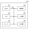
- each functional block may be realized using one device physically or logically coupled, or directly or indirectly (for example, two or more devices physically or logically separated from each other). , Wired, wireless, etc.) and using these multiple devices.
- the functional block may be realized by combining one device or the plurality of devices with software.
- the functions include judgment, decision, judgment, calculation, calculation, processing, derivation, investigation, search, confirmation, reception, transmission, output, access, resolution, selection, selection, establishment, comparison, assumption, expectation, and deemed. , Broadcasting, notifying, communicating, forwarding, configuring, reconfiguring, allocating, mapping, assigning, etc.
- a functional block that makes transmission function may be referred to as a transmitting unit (transmitting unit), a transmitter (transmitter), or the like.
- the realization method is not particularly limited.
- a base station, a user terminal, and the like may function as a computer that performs processing of the wireless communication method according to the present disclosure.
- FIG. 12 is a diagram illustrating an example of a hardware configuration of the base station and the user terminal according to the embodiment.
- the above-described base station 10 and user terminal 20 may be physically configured as a computer device including a processor 1001, a memory 1002, a storage 1003, a communication device 1004, an input device 1005, an output device 1006, a bus 1007, and the like. .
- the term “apparatus” can be read as a circuit, a device, a unit, or the like.
- the hardware configuration of the base station 10 and the user terminal 20 may be configured to include one or more of the devices illustrated in the drawing, or may be configured to exclude some of the devices.
- processor 1001 may be implemented by one or more chips.
- the functions of the base station 10 and the user terminal 20 are performed, for example, by reading predetermined software (program) on hardware such as the processor 1001 and the memory 1002 so that the processor 1001 performs an operation and communicates via the communication device 1004. And controlling at least one of reading and writing of data in the memory 1002 and the storage 1003.
- predetermined software program
- the processor 1001 controls the entire computer by operating an operating system, for example.
- the processor 1001 may be configured by a central processing unit (CPU: Central Processing Unit) including an interface with a peripheral device, a control device, an arithmetic device, a register, and the like.
- CPU Central Processing Unit
- the above-described baseband signal processing unit 104 (204), call processing unit 105, and the like may be realized by the processor 1001.
- the processor 1001 reads out a program (program code), a software module, data, and the like from at least one of the storage 1003 and the communication device 1004 to the memory 1002, and executes various processes according to these.
- a program program code
- a program that causes a computer to execute at least a part of the operation described in the above embodiment is used.
- the control unit 401 of the user terminal 20 may be implemented by a control program stored in the memory 1002 and operated by the processor 1001, and other functional blocks may be similarly implemented.
- the memory 1002 is a computer-readable recording medium, for example, at least one of ROM (Read Only Memory), EPROM (Erasable Programmable ROM), EEPROM (Electrically EPROM), RAM (Random Access Memory), and other appropriate storage media. It may be constituted by one.
- the memory 1002 may be called a register, a cache, a main memory (main storage device), or the like.
- the memory 1002 can store a program (program code), a software module, and the like that can be executed to implement the wireless communication method according to an embodiment of the present disclosure.
- the storage 1003 is a computer-readable recording medium such as a flexible disk, a floppy (registered trademark) disk, a magneto-optical disk (for example, a compact disk (CD-ROM (Compact Disc) ROM, etc.)), a digital versatile disc, At least one of a Blu-ray (registered trademark) disk, a removable disk, a hard disk drive, a smart card, a flash memory device (eg, a card, a stick, a key drive), a magnetic stripe, a database, a server, and other suitable storage media. May be configured.
- the storage 1003 may be called an auxiliary storage device.
- the communication device 1004 is hardware (transmission / reception device) for performing communication between computers via at least one of a wired network and a wireless network, and is also referred to as, for example, a network device, a network controller, a network card, a communication module, or the like.
- the communication device 1004 includes, for example, a high-frequency switch, a duplexer, a filter, a frequency synthesizer, and the like in order to realize at least one of frequency division duplex (FDD: Frequency Division Duplex) and time division duplex (TDD: Time Division Duplex). May be configured.
- FDD Frequency Division Duplex
- TDD Time Division Duplex
- the transmission / reception antenna 101 (201), the amplifier unit 102 (202), the transmission / reception unit 103 (203), the transmission line interface 106, and the like may be realized by the communication device 1004.
- the transmission / reception unit 103 may be physically or logically separated by the transmission unit 103a and the reception unit 103b.
- the input device 1005 is an input device (for example, a keyboard, a mouse, a microphone, a switch, a button, a sensor, and the like) that receives an external input.
- the output device 1006 is an output device that performs output to the outside (for example, a display, a speaker, an LED (Light Emitting Diode) lamp, and the like). Note that the input device 1005 and the output device 1006 may have an integrated configuration (for example, a touch panel).
- the devices such as the processor 1001 and the memory 1002 are connected by a bus 1007 for communicating information.
- the bus 1007 may be configured using a single bus, or may be configured using a different bus for each device.
- the base station 10 and the user terminal 20 include hardware such as a microprocessor, a digital signal processor (DSP), an ASIC (Application Specific Integrated Circuit), a PLD (Programmable Logic Device), and an FPGA (Field Programmable Gate Array). It may be configured to include hardware, and some or all of the functional blocks may be realized using the hardware.
- the processor 1001 may be implemented using at least one of these hardware.
- the channel and the symbol may be a signal (signaling).
- the signal may be a message.
- the reference signal may be abbreviated as RS (Reference Signal), and may be referred to as a pilot, a pilot signal, or the like according to an applied standard.
- a component carrier (CC: Component Carrier) may be called a cell, a frequency carrier, a carrier frequency, or the like.
- the radio frame may be configured by one or a plurality of periods (frames) in the time domain.
- the one or more respective periods (frames) forming the radio frame may be referred to as a subframe.
- a subframe may be configured by one or more slots in the time domain.
- the subframe may be of a fixed length of time (eg, 1 ms) that does not depend on numerology.
- the new melology may be a communication parameter applied to at least one of transmission and reception of a certain signal or channel.
- Numerology includes, for example, subcarrier interval (SCS: SubCarrier @ Spacing), bandwidth, symbol length, cyclic prefix length, transmission time interval (TTI: Transmission @ Time @ Interval), number of symbols per TTI, radio frame configuration, transmission and reception.
- SCS SubCarrier @ Spacing
- TTI Transmission @ Time @ Interval
- TTI Transmission @ Time @ Interval
- radio frame configuration transmission and reception.
- At least one of a specific filtering process performed by the transceiver in the frequency domain and a specific windowing process performed by the transceiver in the time domain may be indicated.
- the slot may be configured by one or more symbols (OFDM (Orthogonal Frequency Division Multiplexing) symbol, SC-FDMA (Single Carrier Frequency Division Multiple Access) symbol, etc.) in the time domain. Further, the slot may be a time unit based on numerology.
- OFDM Orthogonal Frequency Division Multiplexing
- SC-FDMA Single Carrier Frequency Division Multiple Access
- the slot may include a plurality of mini slots.
- Each minislot may be constituted by one or more symbols in the time domain.
- minislots may be called subslots.
- a minislot may be made up of a smaller number of symbols than slots.
- a PDSCH (or PUSCH) transmitted in time units larger than minislots may be referred to as PDSCH (PUSCH) mapping type A.
- a PDSCH (or PUSCH) transmitted using minislots may be referred to as PDSCH (PUSCH) mapping type B.
- Radio frames, subframes, slots, minislots, and symbols all represent time units when transmitting signals.
- the radio frame, the subframe, the slot, the minislot, and the symbol may have different names corresponding thereto. Note that time units such as frames, subframes, slots, minislots, and symbols in the present disclosure may be interchanged with each other.
- one subframe may be called a transmission time interval (TTI: Transmission @ Time @ Interval)
- TTI Transmission @ Time @ Interval
- TTI Transmission Time interval
- TTI Transmission @ Time @ Interval
- TTI Transmission Time interval
- TTI Transmission @ Time @ Interval
- TTI Transmission Time interval
- TTI Transmission @ Time @ Interval
- TTI Transmission Time interval
- TTI Transmission @ Time @ Interval
- TTI Transmission Time interval
- TTI Transmission @ Time @ Interval
- one slot or one minislot is called a TTI.
- TTI means, for example, a minimum time unit of scheduling in wireless communication.
- the base station performs scheduling for allocating radio resources (frequency bandwidth, transmission power, and the like that can be used in each user terminal) to each user terminal in TTI units.
- radio resources frequency bandwidth, transmission power, and the like that can be used in each user terminal
- the TTI may be a transmission time unit such as a channel-encoded data packet (transport block), a code block, a code word, or a processing unit such as scheduling and link adaptation. Note that when a TTI is given, a time section (for example, the number of symbols) in which a transport block, a code block, a codeword, and the like are actually mapped may be shorter than the TTI.
- one slot or one minislot is called a TTI
- one or more TTIs may be the minimum time unit for scheduling. Further, the number of slots (mini-slot number) constituting the minimum time unit of the scheduling may be controlled.
- a TTI having a time length of 1 ms may be called a normal TTI (TTI in LTE@Rel.8-12), a normal TTI, a long TTI, a normal subframe, a normal subframe, a long subframe, a slot, and the like.
- a TTI shorter than the normal TTI may be called a shortened TTI, a short TTI, a partial TTI (partial or fractional TTI), a shortened subframe, a short subframe, a minislot, a subslot, a slot, and the like.
- a long TTI (for example, a normal TTI, a subframe, etc.) may be read as a TTI having a time length exceeding 1 ms, and a short TTI (for example, a shortened TTI, etc.) may be replaced with a TTI shorter than the long TTI and 1 ms.
- the TTI having the TTI length described above may be replaced with the TTI.
- the resource block (RB: Resource Block) is a resource allocation unit in the time domain and the frequency domain, and may include one or a plurality of continuous subcarriers (subcarriers) in the frequency domain.
- the number of subcarriers included in the RB may be the same irrespective of the numerology, and may be, for example, 12.
- the number of subcarriers included in the RB may be determined based on numerology.
- the RB may include one or more symbols in the time domain, and may have a length of one slot, one minislot, one subframe, or one TTI.
- One TTI, one subframe, and the like may each be configured by one or a plurality of resource blocks.
- one or a plurality of RBs include a physical resource block (PRB: Physical @ RB), a subcarrier group (SCG: Sub-Carrier @ Group), a resource element group (REG: Resource @ Element @ Group), a PRB pair, an RB pair, and the like. May be called.
- PRB Physical @ RB
- SCG Sub-Carrier @ Group
- REG Resource @ Element @ Group
- PRB pair an RB pair, and the like. May be called.
- a resource block may be composed of one or more resource elements (RE: Resource @ Element).
- RE Resource @ Element
- one RE may be a radio resource area of one subcarrier and one symbol.
- a bandwidth part (which may also be referred to as a partial bandwidth or the like) may represent a subset of contiguous common RBs (common @ resource @ blocks) for a certain numerology in a certain carrier. Good.
- the common RB may be specified by an index of the RB based on the common reference point of the carrier.
- a PRB may be defined in a BWP and numbered within the BWP.
- $ BWP may include a BWP for UL (UL @ BWP) and a BWP for DL (DL @ BWP).
- BWP for a UE, one or more BWPs may be configured in one carrier.
- At least one of the configured BWPs may be active, and the UE may not have to assume transmitting and receiving a given signal / channel outside the active BWP.
- “cell”, “carrier”, and the like in the present disclosure may be replaced with “BWP”.
- the structures of the above-described radio frame, subframe, slot, minislot, and symbol are merely examples.
- the number of subframes included in a radio frame, the number of slots per subframe or radio frame, the number of minislots included in a slot, the number of symbols and RBs included in a slot or minislot, included in an RB The number of subcarriers, the number of symbols in a TTI, the symbol length, the configuration such as the cyclic prefix (CP) length can be variously changed.
- the information, parameters, and the like described in the present disclosure may be represented using an absolute value, may be represented using a relative value from a predetermined value, or may be represented using another corresponding information. May be represented.
- a radio resource may be indicated by a predetermined index.
- Names used for parameters and the like in the present disclosure are not limited in any way. Further, the formulas and the like using these parameters may be different from those explicitly disclosed in the present disclosure.
- the various channels (PUCCH (Physical Uplink Control Channel), PDCCH (Physical Downlink Control Channel), etc.) and information elements can be identified by any suitable name, so the various names assigned to these various channels and information elements Is not a limiting name in any way.
- the information, signals, etc. described in this disclosure may be represented using any of a variety of different technologies.
- data, instructions, commands, information, signals, bits, symbols, chips, etc. that can be referred to throughout the above description are not limited to voltages, currents, electromagnetic waves, magnetic or magnetic particles, optical or photons, or any of these. May be represented by a combination of
- information, signals, etc. can be output from the upper layer to at least one of the lower layer and the lower layer to the upper layer.
- Information, signals, and the like may be input and output via a plurality of network nodes.
- Information and signals input and output may be stored in a specific location (for example, a memory) or may be managed using a management table. Information and signals that are input and output can be overwritten, updated, or added. The output information, signal, and the like may be deleted. The input information, signal, and the like may be transmitted to another device.
- Notification of information is not limited to the aspect / embodiment described in the present disclosure, and may be performed using another method.
- the information is notified by physical layer signaling (for example, downlink control information (DCI: Downlink Control Information), uplink control information (UCI: Uplink Control Information)), upper layer signaling (for example, RRC (Radio Resource Control) signaling, It may be implemented by broadcast information (master information block (MIB: Master Information Block), system information block (SIB: System Information Block), etc.), MAC (Medium Access Control) signaling), other signals, or a combination thereof.
- DCI Downlink Control Information
- UCI Uplink Control Information
- RRC Radio Resource Control
- MIB Master Information Block
- SIB System Information Block
- MAC Medium Access Control
- the physical layer signaling may be called L1 / L2 (Layer 1 / Layer 2) control information (L1 / L2 control signal), L1 control information (L1 control signal), or the like.
- the RRC signaling may be called an RRC message, and may be, for example, an RRC connection setup (RRCConnectionSetup) message, an RRC connection reconfiguration (RRCConnectionReconfiguration) message, or the like.
- the MAC signaling may be notified using, for example, a MAC control element (MAC @ CE (Control @ Element)).
- the notification of the predetermined information is not limited to an explicit notification, and is implicit (for example, by not performing the notification of the predetermined information or by another information). May be performed).
- the determination may be made by a value represented by 1 bit (0 or 1) or by a boolean value represented by true or false. , May be performed by comparing numerical values (for example, comparison with a predetermined value).
- Software whether called software, firmware, middleware, microcode, hardware description language, or any other name, instructions, instruction sets, codes, code segments, program codes, programs, subprograms, software modules , Applications, software applications, software packages, routines, subroutines, objects, executables, threads of execution, procedures, functions, and the like.
- software, instructions, information, and the like may be transmitted and received via a transmission medium.
- a transmission medium For example, if the software uses at least one of wired technology (coaxial cable, fiber optic cable, twisted pair, digital subscriber line (DSL), etc.) and wireless technology (infrared, microwave, etc.), the website, When transmitted from a server or other remote source, at least one of these wired and / or wireless technologies is included within the definition of a transmission medium.
- system and “network” may be used interchangeably.
- precoding In the present disclosure, “precoding”, “precoder”, “weight (precoding weight)”, “pseudo collocation (QCL: Quasi-Co-Location)”, “transmission power”, “phase rotation”, “antenna port” , “Antenna port group”, “layer”, “number of layers”, “rank”, “beam”, “beam width”, “beam angle”, “antenna”, “antenna element”, “panel”, etc. The terms may be used interchangeably.
- base station (BS: Base @ Station)”, “wireless base station”, “fixed station (fixed @ station)”, “NodeB”, “eNodeB (eNB)”, “gNodeB (gNB)”, “ “Access point (access @ point)”, “transmission point (TP: Transmission @ Point)”, “reception point (RP: Reception @ Point)”, “transmission / reception point (TRP: Transmission / Reception @ Point)", “panel”, “cell” Terms such as, “sector”, “cell group”, “carrier”, “component carrier” may be used interchangeably.
- a base station may be referred to by a term such as a macro cell, a small cell, a femto cell, a pico cell, and the like.
- a base station can accommodate one or more (eg, three) cells. If the base station accommodates multiple cells, the entire coverage area of the base station can be partitioned into multiple smaller areas, each smaller area being a base station subsystem (eg, a small indoor base station (RRH: Communication services can also be provided by Remote Radio ⁇ Head)).
- a base station subsystem eg, a small indoor base station (RRH: Communication services can also be provided by Remote Radio ⁇ Head).
- RRH Small indoor base station
- the term “cell” or “sector” refers to part or all of the coverage area of at least one of a base station and a base station subsystem that provides communication services in this coverage.
- MS mobile station
- UE user equipment
- terminal terminal
- a mobile station is a subscriber station, mobile unit, subscriber unit, wireless unit, remote unit, mobile device, wireless device, wireless communication device, remote device, mobile subscriber station, access terminal, mobile terminal, wireless terminal, remote terminal. , A handset, a user agent, a mobile client, a client or some other suitable terminology.
- At least one of the base station and the mobile station may be called a transmitting device, a receiving device, a communication device, or the like.
- at least one of the base station and the mobile station may be a device mounted on the mobile unit, the mobile unit itself, or the like.
- the moving object may be a vehicle (for example, a car, an airplane, etc.), an unmanned moving object (for example, a drone, a self-driving car, etc.), or a robot (maned or unmanned). ).
- at least one of the base station and the mobile station includes a device that does not necessarily move during a communication operation.
- at least one of the base station and the mobile station may be an IoT (Internet of Things) device such as a sensor.
- IoT Internet of Things
- the base station in the present disclosure may be replaced with a user terminal.
- communication between a base station and a user terminal is replaced with communication between a plurality of user terminals (for example, it may be called D2D (Device-to-Device), V2X (Vehicle-to-Everything), etc.).
- D2D Device-to-Device
- V2X Vehicle-to-Everything
- each aspect / embodiment of the present disclosure may be applied.
- the configuration may be such that the user terminal 20 has the function of the base station 10 described above.
- words such as “up” and “down” may be read as words corresponding to communication between terminals (for example, “side”).
- an uplink channel, a downlink channel, and the like may be replaced with a side channel.
- the user terminal in the present disclosure may be replaced with a base station.
- the base station 10 may have the function of the user terminal 20 described above.
- an operation performed by the base station may be performed by an upper node (upper node) in some cases.
- various operations performed for communication with a terminal include a base station, one or more network nodes other than the base station (eg, Obviously, it can be performed by MME (Mobility @ Management @ Entity), S-GW (Serving-Gateway), etc., but not limited thereto, or a combination thereof.
- Each aspect / embodiment described in the present disclosure may be used alone, may be used in combination, or may be switched and used in execution.
- the order of the processing procedure, sequence, flowchart, and the like of each aspect / embodiment described in the present disclosure may be changed as long as there is no inconsistency.
- elements of the various steps are presented in an exemplary order, and are not limited to the specific order presented.
- LTE Long Term Evolution
- LTE-A Long Term Evolution
- LTE-B Long Term Evolution-Beyond
- SUPER 3G IMT-Advanced
- 4G 4th generation mobile communication
- system 5G (5th generation mobile communication system)
- FRA Fluture Radio Access
- New-RAT Radio Access Technology
- NR New Radio
- NX New radio access
- FX Fluture generation radio access
- GSM Registered trademark
- CDMA2000 Code Division Multiple Access
- UMB Ultra Mobile Broadband
- IEEE 802.11 Wi-Fi (registered trademark)
- IEEE 802.16 WiMAX (registered trademark)
- UWB Ultra-WideBand
- Bluetooth registered trademark
- a system using other appropriate wireless communication methods a next-generation system extended based on these systems, and the like.
- a plurality of systems may be combined (for example, a combination of LTE or LTE-A and 5G) and applied.
- any reference to elements using designations such as "first,” “second,” etc., as used in this disclosure, does not generally limit the quantity or order of those elements. These designations may be used in the present disclosure as a convenient way to distinguish between two or more elements. Thus, reference to a first and second element does not mean that only two elements can be employed or that the first element must precede the second element in some way.
- determining means judging, calculating, computing, processing, deriving, investigating, searching (up, search, inquiry) ( For example, a search in a table, database, or another data structure), ascertaining, etc., may be regarded as "deciding".
- determination includes receiving (eg, receiving information), transmitting (eg, transmitting information), input (input), output (output), and access ( accessing) (e.g., accessing data in a memory) or the like.
- judgment (decision) is regarded as “judgment (decision)” of resolving, selecting, selecting, establishing, comparing, and the like. Is also good. That is, “judgment (decision)” may be regarded as “judgment (decision)” of any operation.
- “judgment (decision)” may be read as “assuming”, “expecting”, “considering”, or the like.
- connection refers to any direct or indirect connection or coupling between two or more elements. And may include the presence of one or more intermediate elements between two elements “connected” or “coupled” to each other.
- the coupling or connection between the elements may be physical, logical, or a combination thereof. For example, “connection” may be read as “access”.
- the radio frequency domain, microwave It can be considered to be “connected” or “coupled” to each other using electromagnetic energy having a wavelength in the region, the light (both visible and invisible) regions, and the like.
- the term “A and B are different” may mean that “A and B are different from each other”.
- the term may mean that “A and B are different from C”.
- Terms such as “separate” and “coupled” may be construed similarly to “different.”
Landscapes
- Engineering & Computer Science (AREA)
- Computer Networks & Wireless Communication (AREA)
- Signal Processing (AREA)
- Databases & Information Systems (AREA)
- Mobile Radio Communication Systems (AREA)
Abstract
複数の処理時間が導入される場合であっても通信を適切に行うために、本開示のユーザ端末の一態様は、所定動作に対して第1の処理時間より短い第2の処理時間をサポートすることを示すUE能力情報を送信する送信部と、前記UE能力情報を送信した後、又は前記第2の処理時間の適用が設定された後に前記所定動作に対して前記第2の処理時間を適用する制御部と、を有する。
Description
本開示は、次世代移動通信システムにおけるユーザ端末及び無線通信方法に関する。
UMTS(Universal Mobile Telecommunications System)ネットワークにおいて、更なる高速データレート、低遅延などを目的としてロングタームエボリューション(LTE:Long Term Evolution)が仕様化された(非特許文献1)。また、LTE(LTE Rel.8、9)の更なる大容量、高度化などを目的として、LTE-A(LTEアドバンスト、LTE Rel.10、11、12、13)が仕様化された。
LTEの後継システム(例えば、FRA(Future Radio Access)、5G(5th generation mobile communication system)、5G+(plus)、NR(New Radio)、NX(New radio access)、FX(Future generation radio access)、LTE Rel.14又は15以降などともいう)も検討されている。
既存のLTEシステム(例えば、LTE Rel.8-14)では、ユーザ端末(UE:User Equipment)は、下り制御チャネル(例えば、PDCCH:Physical Downlink Control Channel)を介して伝送される下り制御情報(DCI:Downlink Control Information、DLアサインメント等ともいう)に基づいて、下り共有チャネル(例えば、PDSCH:Physical Downlink Shared Channel)の受信を制御する。
また、UEは、DCI(ULグラント等ともいう)に基づいて、上り共有チャネル(例えば、PUSCH:Physical Uplink Shared Channel)の送信を制御する。また、UEは、DLデータ(例えば、PDSCH)に対する再送制御情報(HARQ-ACK、ACK/NACK、A/Nなどともいう)等の上り制御情報を、上り制御チャネル(PUCCH:Physical Uplink Control Channel)又は上り共有チャネルを利用して所定タイミングで送信する。
将来の無線通信システム(例えば、5G、5G+、NR、Rel.15以降などともいう)では、要求条件(requirement)が異なる複数の通信(ユースケース、サービス、通信タイプ等ともいう)の送信を同一のUEが行うことが想定される。
なお、要求条件は、例えば、遅延、信頼性、容量(キャパシティ)、速度、性能(performance)の少なくとも一つに関するものであればよい。また、要求条件が異なる通信とは、例えば、高速及び大容量(eMBB:enhanced Mobile Broad Band)、超多数端末(例えば、massive MTC:massive Machine Type Communication)、超高信頼及び低遅延(例えば、URLLC:Ultra Reliable and Low Latency Communications)等である。
このように、要求条件が異なる通信を行う場合、各UEの処理能力(UE能力、又はUE capabilityとも呼ぶ)等に応じて、所定の動作に対して異なる処理時間(processing time)を適用することも想定される。
しかし、複数の処理時間を利用して通信を行う場合、どのように制御するかが問題となるが、具体的な動作等については十分に検討されていない。複数の処理時間を利用した通信が適切に行われない場合、スループットの低下又は通信品質の劣化等が生じるおそれがある。
そこで、本開示は、複数の処理時間が導入される場合であっても通信を適切に行うことができるユーザ端末及び無線通信方法を提供することを目的の1つとする。
本開示の一態様に係るユーザ端末は、所定動作に対して第1の処理時間より短い第2の処理時間をサポートすることを示すUE能力情報を送信する送信部と、前記UE能力情報を送信した後、又は前記第2の処理時間の適用が設定された後に前記所定動作に対して前記第2の処理時間を適用する制御部と、を有することを特徴とする。
本開示の一態様によれば、複数の処理時間が導入される場合であっても通信を適切に行うことができる。
将来の無線通信システム(例えば、NR)では、UEの処理時間(processing time)として複数の処理時間を適用することが検討されている。一例として、第1の処理時間と、当該第1の処理時間より短い第2の処理時間が導入されることが考えられる。
この場合、無線通信システムにおいて、第1の処理時間をサポートするUE能力のみ有するUEと、第2の処理時間をサポートするUE能力を有するUEとが存在していてもよい。第1の処理時間をサポートするUE能力は、第1のUE能力、UE能力#1、UE capability#1、ファーストUE能力、ノーマルUE能力、又は通常UE能力と呼ばれてもよい。第2の処理時間をサポートするUE能力は、第2のUE能力、UE能力#2、UE capability#2、セカンドUE能力、低遅延UE能力、エクステンドUE能力、又は拡張UE能力と呼ばれてもよい。
なお、第2の処理時間をサポートするUE能力(以下、UE能力#2とも記す)は、第1の処理時間をサポートするUE能力(以下、UE能力#1とも記す)を必ず有する構成としてもよい。また、無線通信システムにおいて、全ての端末は少なくともUE能力#1を有する構成としてもよい。
第2の処理時間は、第1の処理時間より短く設定される。例えば、UEがサポートする処理時間(又は、UE能力)に基づいて、下り共有チャネル(PDSCH)に対するHARQ-ACKのフィードバックタイミングが制御されてもよい。つまり、UEがPDSCHを送信してからHARQ-ACKを送信するまでの期間N1(例えば、最小期間)は、第1の処理時間と第2の処理時間に基づいて異なって設定される(図1参照)。
図1Aは第1の処理時間を適用する場合の一例を示し、図1Bは第2の処理時間を適用する場合の一例を示している。図1に示すように、UEは、第2の処理時間を適用(又は、サポートする)場合、第1の処理時間を適用する場合と比較して、PDSCHを受信してからHARQ-ACKを送信するまでの期間N1を短くすることができる。
例えば、UE能力#2を有するUEは、PDSCHを受信してから第2の処理時間(N1)後には、HARQ-ACKの送信準備を完了できる処理能力を有する。第2の処理時間(N1)は、サブキャリア間隔(SCS)毎に定義されてもよく、一例としてSCSが15kHzの場合に第2の処理時間は3シンボル(N1=3)、SCSが30kHzの場合に第2の処理時間は4.5シンボル(N1=4.5)であってもよい。もちろん、第2の処理時間の値はこれに限られず、他のパラメータ等に応じて適宜設定されてもよい。
また、UEがサポートする処理時間(又は、UE能力)に基づいて、下り制御情報(DCI)で指示された上り共有チャネル(PUSCH)の送信タイミングが制御されてもよい。つまり、UEがDCIを受信してからPUSCHを送信するまでの期間N2(例えば、最小期間)は、第1の処理時間と第2の処理時間に基づいて異なって設定される(図2参照)。
図2Aは第1の処理時間を適用する場合の一例を示し、図2Bは第2の処理時間を適用する場合の一例を示している。図2に示すように、UEは、第2の処理時間を適用(又は、サポートする)場合、第1の処理時間を適用する場合と比較して、DCIを受信してからPUSCHを送信するまでの期間N2を短くすることができる。
例えば、UE能力#2を有するUEは、DCIを受信してから第2の処理時間(N2)後には、PUSCHの送信準備を完了できる処理能力を有する。第2の処理時間(N2)は、サブキャリア間隔(SCS)毎に定義されてもよく、一例としてSCSが15kHzの場合に第2の処理時間は5シンボル(N2=5)、SCSが30kHzの場合に第2の処理時間は5.5シンボル(N2=5.5)であってもよい。もちろん、第2の処理時間の値はこれに限られず、他のパラメータ等に応じて適宜設定されてもよい。
このように、複数の処理時間を導入してUEがサポートする処理時間(又は、UE能力)に基づいて通信を制御することにより、要求条件に応じてUE毎に柔軟な制御が可能となる。
しかし、複数の処理時間を導入して通信を行う場合、どのように制御するかが問題となるが、具体的な動作等については十分に検討されていない。例えば、第2の処理時間(又は、UE能力#2)をサポートするUEは、その旨を基地局にUE能力情報として送信することが考えられるが、第2の処理時間の適用タイミングをどのように制御するかが問題となる。複数の処理時間を利用した通信が適切に行われない場合、スループットの低下又は通信品質の劣化等が生じるおそれがある。
そこで、本発明者らは、本実施の形態の一態様として、UEがUE能力情報(例えば、UE能力#2)を基地局に通知する点に着目し、所定条件に基づいて第2の処理時間を適用するタイミングを制御することを着想した。
また、本発明者らは、本実施の形態の他の態様として、UEの処理時間を適用する動作として異なる動作が複数ある点に着目し、第1の処理時間と第2の処理時間を適用する動作をそれぞれ制御することを着想した。
以下、本開示に係る実施形態について、図面を参照して詳細に説明する。各実施の態様は、それぞれ単独で適用されてもよいし、組み合わせて適用されてもよい。また、以下の説明では、第1の処理時間(又は、UE能力#1)と、当該第1の処理時間より短い第2の処理時間(又は、UE能力#2)を例に挙げるが、適用可能な処理時間(又は、UE能力)の数は2種類に限られず、3種類以上であってもよい。また、第1の処理時間と第2の処理時間は、通信における一部の動作(例えば、UE動作)に対しては処理時間が同じ値に定義されてもよい。
(第1の態様)
第1の態様は、所定条件に基づいてUE能力#2に対応する第2の処理時間の適用タイミングを制御する。
第1の態様は、所定条件に基づいてUE能力#2に対応する第2の処理時間の適用タイミングを制御する。
第2の処理時間を適用するための所定条件は、基地局から第2の処理時間の適用がUEに設定(又は、要求)された場合(ケース1)、又はUEが基地局にUE能力情報を通知した場合(ケース2)のいずれかであってもよい。ケース2では、UEに対して基地局から第2の処理時間の適用の設定(又は、要求)は不要となる。
<ケース1>
図3は、少なくとも基地局からUE能力#2に対応する第2の処理時間の適用が設定された後に、UEが第2の処理時間を利用して所定動作を制御する場合の一例を示している。
図3は、少なくとも基地局からUE能力#2に対応する第2の処理時間の適用が設定された後に、UEが第2の処理時間を利用して所定動作を制御する場合の一例を示している。
図3において、UE能力#2をサポートするUEは、サポートする旨をUE能力情報として基地局(又は、ネットワーク)に送信する(ステップ1A)。この場合、UE能力#1をサポートする旨をUE能力情報として別途基地局に送信してもよいし、UE能力#1に関するUE能力情報については基地局に送信しなくてもよい。
UE能力#2をサポートしないUEは、サポートしない旨、又はUE能力#1をサポートする旨を基地局に送信する、あるいは、処理能力に関するUE能力情報として何も基地局に送信しない。
UEからUE能力情報(例えば、UE能力#2)を受信した基地局は、当該UEに対してUE能力#2に対応する第2の処理時間の適用を設定する(ステップ1B)。
UEは、基地局からの設定(又は、通知)に基づいて、設定(又は、再設定)が完了した旨のメッセージ(例えば、Reconf complete message)を基地局に送信する(ステップ1C)。
UEは、ステップ1C以降において、所定動作に対してUE能力#2に対応する第2の処理時間を適用するように制御する。あるいは、UEは、基地局から第2の処理時間の適用が設定された後(例えば、ステップ1B以降)に所定動作に対して第2の処理時間を適用するように制御してもよい。
基地局は、UEに対してUE能力#2に対応する第2の処理時間の適用を設定するタイミング(ステップ1B)、又はUEから設定完了のメッセージを受信するタイミング(ステップ1C)までは、UE能力#1に対応する第1の処理時間が適用されると想定してスケジューリングを制御すればよい。また、基地局は、ステップ1C(又は、ステップ1B)以降に第2の処理時間の適用が可能であると想定してスケジューリングを制御してもよい。
このように、少なくとも基地局から第2の処理時間の適用が設定された後に第2の処理時間を適用することにより、UEは、第2の処理時間を常に考慮して送受信処理を行う必要がなくなる。その結果、UEにおける送受信処理の負荷を低減することができる。
UEは、基地局から第2の処理時間の適用が設定されない場合(例えば、ステップ1Bが行われない、又はステップ1Bで第2の処理時間が設定されない場合)、UE能力#1に対応する第1の処理時間と同じ処理時間が適用されると想定してもよい。
また、第2の処理時間は、DLとULに対して共通に設定されてもよいし、別々に設定されてもよい。また、第2の処理時間は、UE動作毎に設定されてもよい。
また、第2の処理時間は、キャリアアグリゲーション(CA)において、複数のセルグループ(例えば、PUCCHグループ)に含まれる複数CCにわたって共通に設定されてもよいし、CC毎に別々に設定されてもよい。あるいは、第2の処理時間は、デュアルコネクティビティ(DC)において、複数のセルグループに含まれる複数CCにわたって共通に設定されてもよいし、CC毎に別々に設定されてもよい。
<ケース2>
図4は、UEが基地局にUE能力情報(UE能力#2)を送信した後に、UEが第2の処理時間を利用して所定動作を制御する場合の一例を示している。
図4は、UEが基地局にUE能力情報(UE能力#2)を送信した後に、UEが第2の処理時間を利用して所定動作を制御する場合の一例を示している。
図4において、UE能力#2をサポートするUEは、サポートする旨をUE能力情報として基地局(又は、ネットワーク)に送信する(ステップ2A)。この場合、UE能力#1をサポートする旨をUE能力情報として別途基地局に送信してもよいし、UE能力#1に関するUE能力情報については基地局に送信しなくてもよい。
UE能力#2をサポートしないUEは、サポートしない旨、又はUE能力#1をサポートする旨を基地局に送信する、あるいは、処理能力に関するUE能力情報として何も基地局に送信しない。
UEは、ステップ2A以降において、所定動作に対してUE能力#2に対応する第2の処理時間を適用するように制御してもよい。この場合、UEは、UE能力情報を通知した後に、基地局が所定動作に対して第2の処理時間に基づいてスケジューリングを行うと想定して送受信処理を制御してもよい。
基地局は、UEからUE能力情報(UE能力#2)を受信した後(ステップ2A以降)、所定動作に対して第2の処理時間の適用が可能であると想定してスケジューリングを制御してもよい。
このように、UEから基地局に対するUE能力情報(UE能力#2)の通知に基づいて第2の処理時間の適用を行う構成とすることにより、基地局からUEへの送信する情報量(例えば、図3におけるステップ1B、1C等)を削減することができる。
また、UEは、所定条件が満たされた場合に、UE能力#2に対応する第2の処理時間内でPDSCHに関する動作、及びPUSCHに関する動作の少なくとも一方を行う構成としてもよい。PDSCHに関する動作は、例えば、PDSCHに対するHARQ-ACKフィードバックであってもよい。また、PUSCHに関する動作は、例えば、UL送信を指示するDCIに基づくPUSCH送信であってもよい。
所定条件は、少なくとも以下の少なくとも一つの条件(又は、全ての条件)を満たす場合としてもよい。
・キャリアアグリゲーションが非適用の場合
・サービングセルにおけるPDCCH、PDSCH及びPUSCHに対して1つのニューメロロジーが適用される場合
・所定のマッピングタイプ(例えば、マッピングタイプA、B)に基づいてPDSCH又はPUSCHの割当てが制御される場合
・UCIがPUSCHに多重されない場合
・DCIを送信するPDCCHにC-RNTIが適用される(C-RNTIによりCRCスクランブルされる)場合
・キャリアアグリゲーションが非適用の場合
・サービングセルにおけるPDCCH、PDSCH及びPUSCHに対して1つのニューメロロジーが適用される場合
・所定のマッピングタイプ(例えば、マッピングタイプA、B)に基づいてPDSCH又はPUSCHの割当てが制御される場合
・UCIがPUSCHに多重されない場合
・DCIを送信するPDCCHにC-RNTIが適用される(C-RNTIによりCRCスクランブルされる)場合
UEは、所定条件が満たされない場合、PDSCHに関する動作、及びPUSCHに関する動作に対して第2の処理時間を適用することは要求されないと想定してもよい。この場合、UEは、UE能力#1に対応する第1の処理時間内でPDSCHに関する動作、及びPUSCHに関する動作の少なくとも一方を行う構成としてもよい。
<他ケース>
上述したケース1とケース2を組み合わせて利用してもよい。例えば、UEは、基地局にUE能力情報(UE能力#2)を送信した後に、第2の処理時間の適用について基地局から設定された場合に上記ケース1を適用する。一方で、UEは、基地局にUE能力情報(UE能力#2)を送信した後、所定期間内に第2の処理時間の適用について基地局から設定されない場合には上記ケース2を適用する構成としてもよい。
上述したケース1とケース2を組み合わせて利用してもよい。例えば、UEは、基地局にUE能力情報(UE能力#2)を送信した後に、第2の処理時間の適用について基地局から設定された場合に上記ケース1を適用する。一方で、UEは、基地局にUE能力情報(UE能力#2)を送信した後、所定期間内に第2の処理時間の適用について基地局から設定されない場合には上記ケース2を適用する構成としてもよい。
(第2の態様)
第2の態様では、UE能力#2に対応する第2の処理時間を適用するUE動作について説明する。なお、以下に示す構成は、第1の態様のケース1、ケース2、他ケースに対してそれぞれ適用できる。
第2の態様では、UE能力#2に対応する第2の処理時間を適用するUE動作について説明する。なお、以下に示す構成は、第1の態様のケース1、ケース2、他ケースに対してそれぞれ適用できる。
UEは、第2の処理時間(又は、UE能力#2)を有する場合、UE能力#2に対応する第2の処理時間(N1、N2)に基づいてPDSCHに関する動作、及びPUSCHに関する動作の少なくとも一方を行う。N1は、PDSCHに関する動作の処理時間に対応し、N2は、PUSCHに関する動作の処理時間に対応する。
PDSCHに関する動作は、例えば、PDSCHに対するHARQ-ACKフィードバックであってもよい。また、PUSCHに関する動作は、例えば、UL送信を指示するDCIに基づくPUSCH送信であってもよい。
一方で、UEは、PDSCHに対するHARQ-ACKフィードバックに関連する処理、又はUL送信を指示するDCIに基づくPUSCH送信に関連する処理に適用する処理時間をどのように制御するかが問題となる。あるいは、PDSCHに関する動作、及びPUSCHに関する動作以外の動作に適用する処理時間をどのように制御するかが問題となる。以下に、UEが適用する処理時間について説明する。
<態様1>
DL又はULに対してUE能力#2に対応する第2の処理時間が設定された場合であっても、UEは、PDSCHに対するHARQ-ACKフィードバックに関連する処理、又はUL送信を指示するDCIに基づくPUSCH送信に関連する処理に対して第2の処理時間を適用しない。
DL又はULに対してUE能力#2に対応する第2の処理時間が設定された場合であっても、UEは、PDSCHに対するHARQ-ACKフィードバックに関連する処理、又はUL送信を指示するDCIに基づくPUSCH送信に関連する処理に対して第2の処理時間を適用しない。
PDSCHに対するHARQ-ACKフィードバックに関連する処理、又はDCIに基づくPUSCH送信に関連する処理は、UCI(例えば、HARQ-ACK)をPUSCHに多重して送信するUCI on PUSCHの適用、タイミングアドバンス(TA)コマンドの適用、及びTPCコマンドの適用の少なくとも一つであってもよい。
TAコマンドは、上りチャネルの送信タイミング値を示すコマンドであり、MAC制御要素に含まれる。TAコマンドは、無線基地局からユーザ端末に対してMACレイヤでシグナリングされてもよい。TPCコマンドは、ULの送信電力(例えば、PUSCH、PUCCH又はSRS等)の増減値を示し、例えば、PDCCHで送信されるDCIに含まれてもよい。
例えば、UEは、UCI(例えばHARQ-ACK)をPUSCHに多重して送信する場合、HARQ-ACKフィードバックタイミングと、PUSCH送信(又は、PUSCHスケジュール)タイミングについて、第2の処理時間は適用しない。この場合、UEは、第1の処理時間と同じ時間(又は、第1の処理時間より長い時間)をHARQ-ACKフィードバックタイミングと、PUSCH送信(又は、PUSCHスケジュール)タイミング適用してもよい。
また、UEは、TAコマンドの適用についても第1の処理時間に基づいて制御してもよい。同様に、UEは、TPCコマンドの適用についても第1の処理時間に基づいて制御してもよい。この場合、HARQ-ACKフィードバック、及びDCIに基づくPUSCH送信については第2の処理時間を利用して通信のスループットを向上しつつ、送信条件については第1の処理時間を利用するためUEの処理負荷の増加を抑制することができる。
ネットワーク(例えば、基地局)は、UEから報告されたUE能力情報(UE能力#2)を考慮してスケジューリング等を制御する。例えば、基地局は、UCIがPUSCHに多重されないで送信される場合、UE能力#2の第2の処理時間に基づいて、PDSCHに対するHARQ-ACKの送信タイミング、及びULグラントに基づくPUSCHの送信タイミングを制御する。それ以外(例えば、UCI on PUSCHを利用)の場合には、基地局は、UE能力#1の第1の処理時間に基づいて、PDSCHに対するHARQ-ACKの送信タイミング、及びULグラントに基づくPUSCHの送信タイミングを制御してもよい。
また、基地局は、UEから能力情報(UE能力#2)が報告されるか否かに関わらず、TAコマンド及びTPCコマンドの少なくとも一方について、同じタイミング(例えば、第1の処理時間に基づくタイミング)を適用してもよい。
UEは、PUSCHを利用したHARQ-ACK送信、TAコマンドの適用、及びTPCコマンドの適用の少なくとも一つ(又は、全て)が第1の処理時間より短い処理時間(例えば、第2の処理時間)を適用することは想定しなくてもよい。
<態様2>
DL又はULに対してUE能力#2に対応する第2の処理時間が設定された場合、UEは、PDSCHに対するHARQ-ACKフィードバックに関連する処理、又はUL送信を指示するDCIに基づくPUSCH送信に関連する処理に対しても第2の処理時間を適用する。
DL又はULに対してUE能力#2に対応する第2の処理時間が設定された場合、UEは、PDSCHに対するHARQ-ACKフィードバックに関連する処理、又はUL送信を指示するDCIに基づくPUSCH送信に関連する処理に対しても第2の処理時間を適用する。
例えば、UE能力#2をサポートするUEは、UCIをPUSCHに多重して送信する場合、HARQ-ACKフィードバックタイミングと、PUSCH送信(又は、PUSCHスケジュール)タイミングについて、第2の処理時間を適用する。この場合、UE能力#2に対応する第2の処理時間(N1、N2)に基づいてPUSCHに対してHARQ-ACKを多重して送信する。
一方で、UEがUE能力#2をサポートしない場合、UEは、UE能力#2に対応する第2の処理時間(N1、N2)に基づいてPUSCHにHARQ-ACKを多重することは想定しない。この場合、UEは、UE能力#1に対応する第1の処理時間に基づいてPUSCHにHARQ-ACKを多重して送信してもよい。
また、UE能力#2をサポートするUEであっても、UE能力#2に対応する第2の処理時間の適用が基地局から設定されないUE(例えば、上記ケース2)は、第2の処理時間を適用したUCI on PUSCHを行わない構成としてもよい。
また、少なくともULに対してUE能力#2に対応する第2の処理時間が設定されたUEは、UE能力#2(第2の処理時間)に基づいてTAコマンド、及びTPCコマンドの少なくとも一方を適用してもよい。あるいは、第2の処理時間が設定されたUEは、当該第2の処理時間が設定されないUEと比較して、TAコマンドの適用タイミング、及びTPCコマンドの適用タイミングの少なくとも一方を短くなるように制御してもよい。
このように、PDSCHに対するHARQ-ACKフィードバックに関連する処理、又はUL送信を指示するDCIに基づくPUSCH送信に関連する処理に対しても第2の処理時間を適用することにより、基地局から通知される通信条件も早く反映できるため、通信品質を向上することができる。
<態様3>
DL又はULに対してUE能力#2に対応する第2の処理時間が設定される(又は、サポートする)場合であっても、特定の処理又は動作に対しては第2の処理時間を適用しない。特定の処理又は特定の動作は、特定の信号又はチャネルを利用した処理と読み替えてもよい。
DL又はULに対してUE能力#2に対応する第2の処理時間が設定される(又は、サポートする)場合であっても、特定の処理又は動作に対しては第2の処理時間を適用しない。特定の処理又は特定の動作は、特定の信号又はチャネルを利用した処理と読み替えてもよい。
例えば、UE能力#2を有するUEは、SSブロック検出、ランダムアクセス手順(例えば、PRACH送信等)、システム情報(例えば、SIB)、及びページング処理の少なくとも一つ(又は、全部)に対して第2の処理時間を適用しない。UEは、これらの処理に対して第1の処理時間を適用してもよい。
初期接続等に利用する処理(又は、信号、チャネル)に対しては全てのUEに対して共通の処理時間(例えば、第1の処理時間)を適用することにより、処理負荷の増大を抑制することができる。
(第3の態様)
第3の態様では、UE能力(又は、処理時間)を切り替えて適用する。
第3の態様では、UE能力(又は、処理時間)を切り替えて適用する。
第2の態様(例えば、態様3)で示したように、所定の動作に対して第2の処理時間を適用し、当該所定の動作以外に第1の処理時間を適用することも考えられる。また、通信環境又はUEに対する第2の処理時間の設定タイミング等によっては、同じ動作に対して、第1の期間で第1の処理時間を適用し、第2の期間で第2の処理時間を適用することも考えられる。
そのため、UEは、UE能力#1(又は、第1の処理時間)と、UE能力#2(又は、第2の処理時間)と切り替えて適用する構成としてもよい。例えば、UEは、所定のセル(CC又はBWP)において、同じ長さのTTI長又は同じ送信特性を有する処理(又は、信号、チャネル)について第1の処理時間と第2の処理時間を動的に切り替えて適用する。同じ送信特性を有する処理は、復調用参照信号(例えば、DMRS)のマッピングタイプ、及びトランスポートブロックサイズ(TBS)の少なくとも一方が同じである処理であってもよい。
例えば、UEは、所定のRNTIが設定された場合(又は、所定のRTNIが適用された下り制御チャネル(又は、DCI)を受信した場合)にUE能力#1(又は、第1の処理時間)と、UE能力#2(又は、第2の処理時間)と切り替えてもよい。一例として、UEは、所定のRNTIが設定された場合(又は、所定のRTNIが適用されたDCIを受信した場合)、当該RNTIが適応されたDCI(又は、DCIフォーマット)の受信に応じて、UE能力#2(又は、第2の処理時間)を適用するように制御してもよい。
所定のRNTIは、例えば、変調・符号化方式(MCS:Modulation and Coding Scheme)テーブルの選択するためのDCI(PDCCH)に利用されるRNTIであってもよい。あるいは、所定のRNTIは、低遅延及び高信頼性(例えば、URLLC)向けの動作を指示するDCIに利用されるRNTIであってもよい。
また、UEは、所定のRNTIが設定されない場合、適用するUE能力(UE能力#1又はUE能力#2)は、準静的(例えば、RRCシグナリング等の上位レイヤ)により決定される構成としてもよい。
また、UEは、共通サーチスペース(CSS:Common Search Space)で送信されるDCIを受信した場合、所定のUE能力(例えば、UE能力#1(又は、第1の処理時間))を適用してもよい。これにより、UEに共通に送信されるDCIに対しては、既存システムと同様にUE間で同じ処理時間が適用されるため、処理が複雑になることを抑制できる。
あるいは、UEは、第1の態様のケース2で示した所定条件の少なくとも一つ(又は、全て)を満たす場合に、PDSCHに関する動作及びPUSCHに関する動作の少なくとも一方についてUE能力#2に対応する第2の処理時間内で行うように制御してもよい。
また、UEは、所定の時間期間(例えば、スロット)において、先頭から所定シンボル(例えば、3シンボル)以外の時間領域の位置でDCIを検出した場合、適用するUE能力(又は、処理時間)を切り替えてもよい。例えば、スロットの4シンボル以降でDCIを検出した場合、UE能力#1(例えば、第1の処理時間)からUE能力#2(例えば、第2の処理時間)に切り替えてもよい。これにより、DCIを送受信する時間期間に応じてUE能力(又は、処理時間)を動的かつ柔軟に切り替えることができるため、データサイズが大きい場合はUE能力#1(例えば、第1の処理時間)に切り替わるDCI時間期間を用い、低遅延が必要な場合はUE能力#2(例えば、第2の処理時間)に切り替わるDCI時間期間を使う、と言った制御が可能となる。
このように、UEは、特定の状況においてUE能力#2(例えば、第2の処理時間)を適用する(第1の処理時間から第2の処理時間へ切り替える)構成とし、その他の状況ではUE能力#1(例えば、第1の処理時間)を適用する構成としてもよい。
<スキップ制御>
UEは、所定の動作について、UE能力#1(例えば、第1の処理時間)からUE能力#2(例えば、第2の処理時間)に切り替える場合、UE能力#1を適用する所定の動作の少なくとも一部(例えば、所定期間の動作)をスキップするように制御してもよい。以下に、所定の動作がPDSCHに関する動作(PDSCH processing)である場合と、PUSCHに関する動作(PUSCH processing/transmission)である場合のスキップ制御について説明する。
UEは、所定の動作について、UE能力#1(例えば、第1の処理時間)からUE能力#2(例えば、第2の処理時間)に切り替える場合、UE能力#1を適用する所定の動作の少なくとも一部(例えば、所定期間の動作)をスキップするように制御してもよい。以下に、所定の動作がPDSCHに関する動作(PDSCH processing)である場合と、PUSCHに関する動作(PUSCH processing/transmission)である場合のスキップ制御について説明する。
[PDSCHに関する動作]
図5は、スロットnにおいてUE能力#1(例えば、第1の処理時間)からUE能力#2(例えば、第2の処理時間)に切り替える場合の一例を示す。つまり、UEは、スロットnにおいて受信したPDSCHに対するHARQ-ACKフィードバックに対して第2の処理時間を適用する。例えば、UEは、スロットnにおいて受信したPDSCHに対するHARQ-ACKを所定シンボル(例えば、3シンボル)後に相当するスロット(スロットn又はスロットn+1)で送信する。
図5は、スロットnにおいてUE能力#1(例えば、第1の処理時間)からUE能力#2(例えば、第2の処理時間)に切り替える場合の一例を示す。つまり、UEは、スロットnにおいて受信したPDSCHに対するHARQ-ACKフィードバックに対して第2の処理時間を適用する。例えば、UEは、スロットnにおいて受信したPDSCHに対するHARQ-ACKを所定シンボル(例えば、3シンボル)後に相当するスロット(スロットn又はスロットn+1)で送信する。
UEは、UE能力#1を適用するPDSCHに関する動作のうち、所定期間のPDSCHに関する動作(例えば、トランスポートブロック(TB)の復号処理等)をスキップしてもよい。所定期間は、例えば、スロットn-WDLからスロットn-1の少なくとも一部(又は、全部)であってもよい。なお、所定期間はこれに限られず、シンボル単位又はサブフレーム単位で特定される期間であってもよい。
WDLは、例えば、0からk-1の範囲の値を有するUE能力(UE capability)から定まる値であってもよい。なお、kは、DL HARQプロセスタイムに相当する。また、WDLは基地局からUEに設定される値であってもよい。
図5では、一例としてWDLが4である場合を示している。この場合、スロットn-WDLにおいて受信したPDSCHに対するHARQ-ACKを送信するタイミングは、スロットnとなるケースも生じる。同様に、スロットn-WDL+1からスロットn-1おいて受信したPDSCHに対するHARQ-ACKを送信するタイミングは、スロットn以降となるケースも生じる。つまり、UEは、スロットnにおいて、スロットn-1以前に受信したPDSCHに対するHARQ-ACKの送信処理を行う必要がある。
一方で、上述したように、スロットnにおいて受信したPDSCHに対するHARQ-ACKフィードバックに対して第2の処理時間を適用する場合、当該HARQ-ACKをスロットn又はスロットn+1で送信することも考えられる。したがって、第1の処理時間を適用する所定期間のPDSCHに関する動作(例えば、TBの復号等)をスキップすることにより、UEの処理負荷を低減し第2の処理時間を適用したHARQ-ACKを適切に行うことができる。また、第1の処理時間を適用したHARQ-ACKと、第2の処理時間を適用したHARQ-ACKの送信タイミングが衝突することを抑制できる。
所定期間に対するスキップ動作の適用有無、又はスキップ動作を適用する期間は、UEが自律的に決定してもよい。PDSCHに関する動作をスキップ(例えば、TBの復号をスキップ)する場合、UEは、TBが復号できなかった(TBの復号が失敗した)ことを物理レイヤ(physical layer)から上位レイヤ(higher layer)に通知してもよい。あるいは、基地局からUEに対して、所定期間に対するスキップ動作の適用有無、又はスキップ動作を適用する期間を設定してもよいし、仕様であらかじめ定めてもよい。
また、UEは、第2の処理時間が適用される期間等を考慮して、スキップするPDSCHの数が出来るだけ少なくなるように制御してもよい。また、UEは、UE能力#1を適用する所定期間のPDSCHに関する動作をスキップする場合、全てのCCにおける動作をスキップしてもよい。これにより、UEにおける処理負荷を出来るだけ低減できるため、UE能力#2を利用した動作を適切に行うことができる。なお、一部のCC(例えば、PCell、PSCell)等はスキップしない構成としてもよい。
あるいは、UEは、UE能力#1を適用する所定期間のPDSCHに関する動作をスキップする場合、所定CC(例えば、UE能力#2を適用するCC)における動作をスキップしてもよい。これにより、他のCCの動作に影響させずに通信を行うことができる。
[PUSCHに関する動作]
図6は、スロットnにおいてUE能力#1(例えば、第1の処理時間)からUE能力#2(例えば、第2の処理時間)に切り替える場合の一例を示す。つまり、UEは、スロットnにおいて受信したDCIに基づくPUSCH送信に対して第2の処理時間を適用する。例えば、UEは、スロットnにおいて受信したDCIに基づくPUSCHを所定シンボル(例えば、5シンボル)後に相当するスロット(スロットn又はスロットn+1)で送信する。
図6は、スロットnにおいてUE能力#1(例えば、第1の処理時間)からUE能力#2(例えば、第2の処理時間)に切り替える場合の一例を示す。つまり、UEは、スロットnにおいて受信したDCIに基づくPUSCH送信に対して第2の処理時間を適用する。例えば、UEは、スロットnにおいて受信したDCIに基づくPUSCHを所定シンボル(例えば、5シンボル)後に相当するスロット(スロットn又はスロットn+1)で送信する。
UEは、UE能力#1を適用するPUSCHに関する動作のうち、所定期間のPUSCHに関する動作(例えば、DCI又は所定DCIフォーマットに対応するPDCCHのモニタ等)をスキップしてもよい。所定期間は、例えば、スロットn-WULからスロットn-1の少なくとも一部(又は、全部)であってもよい。なお、所定期間はこれに限られず、シンボル単位又はサブフレーム単位で特定される期間であってもよい。
WULは、例えば、0からk-1の範囲の値を有するUE能力(UE capability)から定まる値であってもよい。なお、kは、ULスケジューリングタイムに相当する。また、WULは基地局からUEに設定される値であってもよい。
図6では、一例としてWULが4である場合を示している。この場合、スロットn-WULにおいて受信したDCIに基づくPUSCHの送信タイミングは、スロットnとなるケースも生じる。同様に、スロットn-WUL+1からスロットn-1おいて受信したDCIに基づくPUSCH送信タイミングは、スロットn以降となるケースも生じる。つまり、UEは、スロットnにおいて、スロットn-1以前に受信したDCIに基づくPUSCHの送信処理を行う必要がある。
一方で、上述したように、スロットnにおいて受信したDCIに基づくPUSCH送信に対して第2の処理時間を適用する場合、当該PUSCHをスロットn又はスロットn+1で送信することも考えられる。したがって、第1の処理時間を適用する所定期間のPUSCHに関する動作(例えば、TBの復号等)をスキップすることにより、UEの処理負荷を低減し第2の処理時間を適用したPUSCHを適切に行うことができる。また、第1の処理時間を適用したPUSCHと、第2の処理時間を適用したPUSCHの送信タイミングが衝突することを抑制できる。
所定期間に対するスキップ動作の適用有無、又はスキップ動作を適用する期間は、UEが自律的に決定してもよい。PUSCHに関する動作をスキップ(例えば、所定のDCIフォーマットに対応するPDCCHのモニタをスキップ)する場合、UEは、発行されたPUSCHの送信指示(PUSCHグラント)に基づいて上位レイヤからのデータを要求してもよい。例えば、送信前にリスニングを適用するLAAづさにおけるスキップ時と同様の処理を行ってもよい。
あるいは、基地局からUEに対して、所定期間に対するスキップ動作の適用有無、又はスキップ動作を適用する期間を設定してもよいし、仕様であらかじめ定めてもよい。
また、UEは、第2の処理時間が適用される期間等を考慮して、スキップするPUSCHの数が出来るだけ少なくなるように制御してもよい。また、UEは、UE能力#1を適用する所定期間のPUSCHに関する動作をスキップする場合、全てのCCにおける動作をスキップしてもよい。これにより、UEにおける処理負荷を出来るだけ低減できるため、UE能力#2を利用した動作を適切に行うことができる。なお、一部のCC(例えば、PCell、PSCell)等はスキップしない構成としてもよい。
あるいは、UEは、UE能力#1を適用する所定期間のPUSCHに関する動作をスキップする場合、所定CC(例えば、UE能力#2を適用するCC)における動作をスキップしてもよい。これにより、他のCCの動作に影響させずに通信を行うことができる。
(第4の態様)
第4の態様では、複数のセルを利用して通信を行う場合(例えば、CA利用時)におけるUE能力情報の通知方法、設定方法等について説明する。なお、以下の説明ではキャリアアグリゲーション(CA)を適用する場合を示すが、デュアルコネクティビティ(DC)場合にも同様に適用してもよい。
第4の態様では、複数のセルを利用して通信を行う場合(例えば、CA利用時)におけるUE能力情報の通知方法、設定方法等について説明する。なお、以下の説明ではキャリアアグリゲーション(CA)を適用する場合を示すが、デュアルコネクティビティ(DC)場合にも同様に適用してもよい。
CAを適用する場合、UEは、各サブキャリア間隔(SCS)についてUE能力#2(例えば、第2の処理時間)のサポート有無、ULに対するサポート有無、及びDLに対するサポート有無の少なくとも一つを基地局に送信する。
これに加えて、UEは、UE能力(例えば、UE能力#2)が設定可能なCA構成を送信してもよい。例えば、CA構成は、UE能力が設定可能なCAバンドの組み合わせ、最大CC数、複数CCにおけるサブキャリア間隔の組み合わせ、複数CCにおけるスロット又は1ms毎のトランスポートブロックの最大ビット数であってもよい。CCは全てのフレーム構成タイプを適用可能なCCとしてもよい。
また、UE能力#2がPUCCHグループに含まれるいずれかのセカンダリセルに設定された場合、PUCCHを送信するセル(PUCCHセル、PUCCH SCellとも呼ぶ)についてもUE能力#2が設定される構成としてもよい。この場合、所定のSCellで受信したPDSCHに対するHARQ-ACKフィードバックに対して、UE能力#2を適用してPUCCHセルで送信することができる。
PUCCHグループは、PUCCHの送信を行うセル(PCell又はPUCCH SCell)に対応づけられるセカンダリセルを含む複数のセルで構成されるグループである。例えば、PUCCH SCellに対応づけられるセカンダリセルのUCIは、PUCCH SCellのPUCCHに多重して送信を行う。
あるいは、UE能力#2がPUCCHグループに含まれるいずれかのセカンダリセルに設定された場合、PUCCHを送信するセルにはUE能力#2が必ずしも設定されない構成としてもよい。PUCCHセルにUE能力#2が設定されない場合、所定のSCellで受信したPDSCHに対するHARQ-ACKフィードバックに対して、UE能力#2を適用してPUCCHセルで送信してもよい。あるいは、PUCCHセルにUE能力#2が設定されない場合、所定のSCellで受信したPDSCHに対するHARQ-ACKフィードバックに対して、UE能力#2を適用しない構成としてもよい。
また、UE能力#2は、DLのみ行うセル、ULのみ行うセル(SUL(Supplemental UpLink)セルとも呼ぶ)に設定されてもよい。
UE能力#2(例えば、第2の処理時間)を適用する場合、クロスキャリアスケジューリングはサポートされない構成としてもよい。これにより、クロスキャリアスケジューリングを行う場合には、UE能力#1(例えば、第1の処理時間)を考慮してスケジューリングを制御すればよいため、処理の複雑化を抑制できる。
あるいは、UE能力#2(例えば、第2の処理時間)を適用する場合、クロスキャリアスケジューリングはサポートされる構成としてもよい。この場合、同じPUCCHグループ内でクロスキャリアスケジューリングが適用される構成としてもよい。
また、UE能力#2の適用時にクロスキャリアスケジューリングをサポートする場合、スケジューリングセル(DCIが送信されるセル)とスケジューリングされるセル(PDSCHが送信されるセル)の両方に対してUE能力#2が設定される構成としてもよい。あるいは、一方のセルに対してUE能力#1が設定され、他方のセルに対してUE能力#2が設定される構成としてもよい。
UEは、UE能力情報として報告モード(例えば、タイプ1、2等)毎にCSIプロセスの最大数を報告する。UE能力#2(例えば、第2の処理時間)を適用する場合には、CSIプロセスの最大数等が変更される場合がある。そのため、UE(又は、基地局)は、UE能力#2を適用する場合、当該UE能力#2に基づいてCSIプロセスの最大数を更新(アップデート)してもよい。なお、CSIプロセス数に限らず、UE能力#2の適用により条件が変更されるパラメータについては、UE能力#2の適用に応じて適宜アップデートする構成としてもよい。
また、UEは、所定のUE能力を報告した場合、異なるキャリアにわたる異なるTTI長を利用した同時送信が許容される構成としてもよい。当該同時送信は、セルグループ又はPUCCHセルグループ内でのみ許容される構成としてもよい。
(無線通信システム)
以下、本実施の形態に係る無線通信システムの構成について説明する。この無線通信システムでは、上記複数の態様の少なくとも一つの組み合わせを用いて通信が行われる。
以下、本実施の形態に係る無線通信システムの構成について説明する。この無線通信システムでは、上記複数の態様の少なくとも一つの組み合わせを用いて通信が行われる。
図7は、本実施の形態に係る無線通信システムの概略構成の一例を示す図である。無線通信システム1では、LTEシステムのシステム帯域幅(例えば、20MHz)を1単位とする複数の基本周波数ブロック(コンポーネントキャリア)を一体としたキャリアアグリゲーション(CA)及び/又はデュアルコネクティビティ(DC)を適用することができる。
なお、無線通信システム1は、LTE(Long Term Evolution)、LTE-A(LTE-Advanced)、LTE-B(LTE-Beyond)、SUPER 3G、IMT-Advanced、4G(4th generation mobile communication system)、5G(5th generation mobile communication system)、NR(New Radio)、FRA(Future Radio Access)、New-RAT(Radio Access Technology)などと呼ばれてもよいし、これらを実現するシステムと呼ばれてもよい。
無線通信システム1は、比較的カバレッジの広いマクロセルC1を形成する無線基地局11と、マクロセルC1内に配置され、マクロセルC1よりも狭いスモールセルC2を形成する無線基地局12(12a-12c)と、を備えている。また、マクロセルC1及び各スモールセルC2には、ユーザ端末20が配置されている。各セル及びユーザ端末20の配置、数などは、図に示す態様に限定されない。
ユーザ端末20は、無線基地局11及び無線基地局12の双方に接続することができる。ユーザ端末20は、マクロセルC1及びスモールセルC2を、CA又はDCを用いて同時に使用することが想定される。また、ユーザ端末20は、複数のセル(CC)(例えば、5個以下のCC、6個以上のCC)を用いてCA又はDCを適用してもよい。
ユーザ端末20と無線基地局11との間は、相対的に低い周波数帯域(例えば、2GHz)で帯域幅が狭いキャリア(既存キャリア、legacy carrierなどとも呼ばれる)を用いて通信を行うことができる。一方、ユーザ端末20と無線基地局12との間は、相対的に高い周波数帯域(例えば、3.5GHz、5GHzなど)で帯域幅が広いキャリアが用いられてもよいし、無線基地局11との間と同じキャリアが用いられてもよい。なお、各無線基地局が利用する周波数帯域の構成はこれに限られない。
また、ユーザ端末20は、各セルで、時分割複信(TDD:Time Division Duplex)及び/又は周波数分割複信(FDD:Frequency Division Duplex)を用いて通信を行うことができる。また、各セル(キャリア)では、単一のニューメロロジーが適用されてもよいし、複数の異なるニューメロロジーが適用されてもよい。
ニューメロロジーとは、ある信号及び/又はチャネルの送信及び/又は受信に適用される通信パラメータであってもよく、例えば、サブキャリア間隔、帯域幅、シンボル長、サイクリックプレフィックス長、サブフレーム長、TTI長、TTIあたりのシンボル数、無線フレーム構成、フィルタリング処理、ウィンドウイング処理などの少なくとも1つを示してもよい。
無線基地局11と無線基地局12との間(又は、2つの無線基地局12間)は、有線(例えば、CPRI(Common Public Radio Interface)に準拠した光ファイバ、X2インターフェースなど)又は無線によって接続されてもよい。
無線基地局11及び各無線基地局12は、それぞれ上位局装置30に接続され、上位局装置30を介してコアネットワーク40に接続される。なお、上位局装置30には、例えば、アクセスゲートウェイ装置、無線ネットワークコントローラ(RNC)、モビリティマネジメントエンティティ(MME)などが含まれるが、これに限定されない。また、各無線基地局12は、無線基地局11を介して上位局装置30に接続されてもよい。
なお、無線基地局11は、相対的に広いカバレッジを有する無線基地局であり、マクロ基地局、集約ノード、eNB(eNodeB)、送受信ポイント、などと呼ばれてもよい。また、無線基地局12は、局所的なカバレッジを有する無線基地局であり、スモール基地局、マイクロ基地局、ピコ基地局、フェムト基地局、HeNB(Home eNodeB)、RRH(Remote Radio Head)、送受信ポイントなどと呼ばれてもよい。以下、無線基地局11及び12を区別しない場合は、無線基地局10と総称する。
各ユーザ端末20は、LTE、LTE-Aなどの各種通信方式に対応した端末であり、移動通信端末(移動局)だけでなく固定通信端末(固定局)を含んでもよい。
無線通信システム1においては、無線アクセス方式として、下りリンクに直交周波数分割多元接続(OFDMA:Orthogonal Frequency Division Multiple Access)が適用され、上りリンクにシングルキャリア-周波数分割多元接続(SC-FDMA:Single Carrier Frequency Division Multiple Access)及び/又はOFDMAが適用される。
OFDMAは、周波数帯域を複数の狭い周波数帯域(サブキャリア)に分割し、各サブキャリアにデータをマッピングして通信を行うマルチキャリア伝送方式である。SC-FDMAは、システム帯域幅を端末毎に1つ又は連続したリソースブロックによって構成される帯域に分割し、複数の端末が互いに異なる帯域を用いることで、端末間の干渉を低減するシングルキャリア伝送方式である。なお、上り及び下りの無線アクセス方式は、これらの組み合わせに限らず、他の無線アクセス方式が用いられてもよい。
無線通信システム1では、下りリンクのチャネルとして、各ユーザ端末20で共有される下り共有チャネル(PDSCH:Physical Downlink Shared Channel)、ブロードキャストチャネル(PBCH:Physical Broadcast Channel)、下りL1/L2制御チャネルなどが用いられる。PDSCHによって、ユーザデータ、上位レイヤ制御情報、SIB(System Information Block)などが伝送される。また、PBCHによって、MIB(Master Information Block)が伝送される。
下りL1/L2制御チャネルは、下り制御チャネル(PDCCH(Physical Downlink Control Channel)及び/又はEPDCCH(Enhanced Physical Downlink Control Channel))、PCFICH(Physical Control Format Indicator Channel)、PHICH(Physical Hybrid-ARQ Indicator Channel)の少なくとも一つを含む。PDCCHによって、PDSCH及び/又はPUSCHのスケジューリング情報を含む下り制御情報(DCI:Downlink Control Information)などが伝送される。
なお、DCIによってスケジューリング情報が通知されてもよい。例えば、DLデータ受信をスケジューリングするDCIは、DLアサインメントと呼ばれてもよいし、ULデータ送信をスケジューリングするDCIは、ULグラントと呼ばれてもよい。
PCFICHによって、PDCCHに用いるOFDMシンボル数が伝送される。PHICHによって、PUSCHに対するHARQ(Hybrid Automatic Repeat reQuest)の送達確認情報(例えば、再送制御情報、HARQ-ACK、ACK/NACKなどともいう)が伝送される。EPDCCHは、PDSCH(下り共有データチャネル)と周波数分割多重され、PDCCHと同様にDCIなどの伝送に用いられる。
無線通信システム1では、上りリンクのチャネルとして、各ユーザ端末20で共有される上り共有チャネル(PUSCH:Physical Uplink Shared Channel)、上り制御チャネル(PUCCH:Physical Uplink Control Channel)、ランダムアクセスチャネル(PRACH:Physical Random Access Channel)などが用いられる。PUSCHによって、ユーザデータ、上位レイヤ制御情報などが伝送される。また、PUCCHによって、下りリンクの無線リンク品質情報(CQI:Channel Quality Indicator)、送達確認情報、スケジューリングリクエスト(SR:Scheduling Request)などが伝送される。PRACHによって、セルとの接続確立のためのランダムアクセスプリアンブルが伝送される。
無線通信システム1では、下り参照信号として、セル固有参照信号(CRS:Cell-specific Reference Signal)、チャネル状態情報参照信号(CSI-RS:Channel State Information-Reference Signal)、復調用参照信号(DMRS:DeModulation Reference Signal)、位置決定参照信号(PRS:Positioning Reference Signal)などが伝送される。また、無線通信システム1では、上り参照信号として、測定用参照信号(SRS:Sounding Reference Signal)、復調用参照信号(DMRS)などが伝送される。なお、DMRSはユーザ端末固有参照信号(UE-specific Reference Signal)と呼ばれてもよい。また、伝送される参照信号は、これらに限られない。
<無線基地局>
図8は、本実施の形態に係る無線基地局の全体構成の一例を示す図である。無線基地局10は、複数の送受信アンテナ101と、アンプ部102と、送受信部103と、ベースバンド信号処理部104と、呼処理部105と、伝送路インターフェース106と、を備えている。なお、送受信アンテナ101、アンプ部102、送受信部103は、それぞれ1つ以上を含むように構成されればよい。
図8は、本実施の形態に係る無線基地局の全体構成の一例を示す図である。無線基地局10は、複数の送受信アンテナ101と、アンプ部102と、送受信部103と、ベースバンド信号処理部104と、呼処理部105と、伝送路インターフェース106と、を備えている。なお、送受信アンテナ101、アンプ部102、送受信部103は、それぞれ1つ以上を含むように構成されればよい。
下りリンクによって無線基地局10からユーザ端末20に送信されるユーザデータは、上位局装置30から伝送路インターフェース106を介してベースバンド信号処理部104に入力される。
ベースバンド信号処理部104では、ユーザデータに関して、PDCP(Packet Data Convergence Protocol)レイヤの処理、ユーザデータの分割・結合、RLC(Radio Link Control)再送制御などのRLCレイヤの送信処理、MAC(Medium Access Control)再送制御(例えば、HARQの送信処理)、スケジューリング、伝送フォーマット選択、チャネル符号化、逆高速フーリエ変換(IFFT:Inverse Fast Fourier Transform)処理、プリコーディング処理などの送信処理が行われて送受信部103に転送される。また、下り制御信号に関しても、チャネル符号化、逆高速フーリエ変換などの送信処理が行われて、送受信部103に転送される。
送受信部103は、ベースバンド信号処理部104からアンテナ毎にプリコーディングして出力されたベースバンド信号を無線周波数帯に変換して送信する。送受信部103で周波数変換された無線周波数信号は、アンプ部102によって増幅され、送受信アンテナ101から送信される。送受信部103は、本開示に係る技術分野での共通認識に基づいて説明されるトランスミッター/レシーバー、送受信回路又は送受信装置から構成することができる。なお、送受信部103は、一体の送受信部として構成されてもよいし、送信部及び受信部から構成されてもよい。
一方、上り信号については、送受信アンテナ101で受信された無線周波数信号がアンプ部102で増幅される。送受信部103はアンプ部102で増幅された上り信号を受信する。送受信部103は、受信信号をベースバンド信号に周波数変換して、ベースバンド信号処理部104に出力する。
ベースバンド信号処理部104では、入力された上り信号に含まれるユーザデータに対して、高速フーリエ変換(FFT:Fast Fourier Transform)処理、逆離散フーリエ変換(IDFT:Inverse Discrete Fourier Transform)処理、誤り訂正復号、MAC再送制御の受信処理、RLCレイヤ及びPDCPレイヤの受信処理がなされ、伝送路インターフェース106を介して上位局装置30に転送される。呼処理部105は、通信チャネルの呼処理(設定、解放など)、無線基地局10の状態管理、無線リソースの管理などを行う。
伝送路インターフェース106は、所定のインターフェースを介して、上位局装置30と信号を送受信する。また、伝送路インターフェース106は、基地局間インターフェース(例えば、CPRI(Common Public Radio Interface)に準拠した光ファイバ、X2インターフェース)を介して他の無線基地局10と信号を送受信(バックホールシグナリング)してもよい。
なお、送受信部103は、アナログビームフォーミングを実施するアナログビームフォーミング部をさらに有してもよい。アナログビームフォーミング部は、本発明に係る技術分野での共通認識に基づいて説明されるアナログビームフォーミング回路(例えば、位相シフタ、位相シフト回路)又はアナログビームフォーミング装置(例えば、位相シフト器)から構成することができる。また、送受信アンテナ101は、例えばアレーアンテナにより構成することができる。また、送受信部103は、シングルBF、マルチBFを適用できるように構成されている。
送受信部103は、送信ビームを用いて信号を送信してもよいし、受信ビームを用いて信号を受信してもよい。送受信部103は、制御部301によって決定された所定のビームを用いて信号を送信及び/又は受信してもよい。
また、送受信部103は、ユーザ端末20に対して下り(DL)信号(DLデータ信号(下り共有チャネル)、DL制御信号(下り制御チャネル)、DL参照信号の少なくとも一つを含む)を送信し、当該ユーザ端末20からの上り(UL)信号(ULデータ信号、UL制御信号、UL参照信号の少なくとも一つを含む)を受信する。
また、送受信部103は、所定動作に対して第1の処理時間より短い第2の処理時間をサポートすることを示すUE能力情報(例えば、UE能力#2)を受信する。また、送受信部103は、UE能力#2に関する情報を受信した場合、当該UE能力#2に対応する第2の処理時間を設定する情報を送信してもよい。また、送受信部103は、(再)設定完成メッセージ(Reconf complete message)を受信してもよい。
図9は、本実施の形態に係る無線基地局の機能構成の一例を示す図である。なお、本例では、本実施の形態における特徴部分の機能ブロックを主に示しており、無線基地局10は、無線通信に必要な他の機能ブロックも有すると想定されてもよい。
ベースバンド信号処理部104は、制御部(スケジューラ)301と、送信信号生成部302と、マッピング部303と、受信信号処理部304と、測定部305と、を少なくとも備えている。なお、これらの構成は、無線基地局10に含まれていればよく、一部又は全部の構成がベースバンド信号処理部104に含まれなくてもよい。
制御部(スケジューラ)301は、無線基地局10全体の制御を実施する。制御部301は、本開示に係る技術分野での共通認識に基づいて説明されるコントローラ、制御回路又は制御装置から構成することができる。
制御部301は、例えば、送信信号生成部302における信号の生成、マッピング部303における信号の割り当てなどを制御する。また、制御部301は、受信信号処理部304における信号の受信処理、測定部305における信号の測定などを制御する。
制御部301は、システム情報、下りデータ信号(例えば、PDSCHで送信される信号)、下り制御信号(例えば、PDCCH及び/又はEPDCCHで送信される信号。送達確認情報など)のスケジューリング(例えば、リソース割り当て)を制御する。また、制御部301は、上りデータ信号に対する再送制御の要否を判定した結果などに基づいて、下り制御信号、下りデータ信号などの生成を制御する。
制御部301は、UEから送信されるUE能力情報(例えば、UE能力#2)に基づいて、UE能力#2に対応する第2の処理時間を考慮してスケジューリングを制御してもよい。
送信信号生成部302は、制御部301からの指示に基づいて、下り信号(下り制御信号、下りデータ信号、下り参照信号など)を生成して、マッピング部303に出力する。送信信号生成部302は、本開示に係る技術分野での共通認識に基づいて説明される信号生成器、信号生成回路又は信号生成装置から構成することができる。
送信信号生成部302は、例えば、制御部301からの指示に基づいて、下りデータの割り当て情報を通知するDLアサインメント及び/又は上りデータの割り当て情報を通知するULグラントを生成する。DLアサインメント及びULグラントは、いずれもDCIであり、DCIフォーマットに従う。また、下りデータ信号には、各ユーザ端末20からのチャネル状態情報(CSI:Channel State Information)などに基づいて決定された符号化率、変調方式などに従って符号化処理、変調処理などが行われる。
マッピング部303は、制御部301からの指示に基づいて、送信信号生成部302で生成された下り信号を、所定の無線リソースにマッピングして、送受信部103に出力する。マッピング部303は、本開示に係る技術分野での共通認識に基づいて説明されるマッパー、マッピング回路又はマッピング装置から構成することができる。
受信信号処理部304は、送受信部103から入力された受信信号に対して、受信処理(例えば、デマッピング、復調、復号など)を行う。ここで、受信信号は、例えば、ユーザ端末20から送信される上り信号(上り制御信号、上りデータ信号、上り参照信号など)である。受信信号処理部304は、本開示に係る技術分野での共通認識に基づいて説明される信号処理器、信号処理回路又は信号処理装置から構成することができる。
受信信号処理部304は、受信処理によって復号された情報を制御部301に出力する。例えば、HARQ-ACKを含むPUCCHを受信した場合、HARQ-ACKを制御部301に出力する。また、受信信号処理部304は、受信信号及び/又は受信処理後の信号を、測定部305に出力する。
測定部305は、受信した信号に関する測定を実施する。測定部305は、本開示に係る技術分野での共通認識に基づいて説明される測定器、測定回路又は測定装置から構成することができる。
例えば、測定部305は、受信した信号に基づいて、RRM(Radio Resource Management)測定、CSI(Channel State Information)測定などを行ってもよい。測定部305は、受信電力(例えば、RSRP(Reference Signal Received Power))、受信品質(例えば、RSRQ(Reference Signal Received Quality)、SINR(Signal to Interference plus Noise Ratio)、SNR(Signal to Noise Ratio))、信号強度(例えば、RSSI(Received Signal Strength Indicator))、伝搬路情報(例えば、CSI)などについて測定してもよい。測定結果は、制御部301に出力されてもよい。
<ユーザ端末>
図10は、本実施の形態に係るユーザ端末の全体構成の一例を示す図である。ユーザ端末20は、複数の送受信アンテナ201と、アンプ部202と、送受信部203と、ベースバンド信号処理部204と、アプリケーション部205と、を備えている。なお、送受信アンテナ201、アンプ部202、送受信部203は、それぞれ1つ以上を含むように構成されればよい。
図10は、本実施の形態に係るユーザ端末の全体構成の一例を示す図である。ユーザ端末20は、複数の送受信アンテナ201と、アンプ部202と、送受信部203と、ベースバンド信号処理部204と、アプリケーション部205と、を備えている。なお、送受信アンテナ201、アンプ部202、送受信部203は、それぞれ1つ以上を含むように構成されればよい。
送受信アンテナ201で受信された無線周波数信号は、アンプ部202で増幅される。送受信部203は、アンプ部202で増幅された下り信号を受信する。送受信部203は、受信信号をベースバンド信号に周波数変換して、ベースバンド信号処理部204に出力する。送受信部203は、本開示に係る技術分野での共通認識に基づいて説明されるトランスミッター/レシーバー、送受信回路又は送受信装置から構成することができる。なお、送受信部203は、一体の送受信部として構成されてもよいし、送信部及び受信部から構成されてもよい。
ベースバンド信号処理部204は、入力されたベースバンド信号に対して、FFT処理、誤り訂正復号、再送制御の受信処理などを行う。下りリンクのユーザデータは、アプリケーション部205に転送される。アプリケーション部205は、物理レイヤ及びMACレイヤより上位のレイヤに関する処理などを行う。また、下りリンクのデータのうち、ブロードキャスト情報もアプリケーション部205に転送されてもよい。
一方、上りリンクのユーザデータについては、アプリケーション部205からベースバンド信号処理部204に入力される。ベースバンド信号処理部204では、再送制御の送信処理(例えば、HARQの送信処理)、チャネル符号化、プリコーディング、離散フーリエ変換(DFT:Discrete Fourier Transform)処理、IFFT処理などが行われて送受信部203に転送される。
送受信部203は、ベースバンド信号処理部204から出力されたベースバンド信号を無線周波数帯に変換して送信する。送受信部203で周波数変換された無線周波数信号は、アンプ部202によって増幅され、送受信アンテナ201から送信される。
なお、送受信部203は、アナログビームフォーミングを実施するアナログビームフォーミング部をさらに有してもよい。アナログビームフォーミング部は、本発明に係る技術分野での共通認識に基づいて説明されるアナログビームフォーミング回路(例えば、位相シフタ、位相シフト回路)又はアナログビームフォーミング装置(例えば、位相シフト器)から構成することができる。また、送受信アンテナ201は、例えばアレーアンテナにより構成することができる。また、送受信部203は、シングルBF、マルチBFを適用できるように構成されている。
送受信部203は、送信ビームを用いて信号を送信してもよいし、受信ビームを用いて信号を受信してもよい。送受信部203は、制御部401によって決定された所定のビームを用いて信号を送信及び/又は受信してもよい。
また、送受信部203は、無線基地局10から下り(DL)信号(DLデータ信号(下り共有チャネル)、DL制御信号(下り制御チャネル)、DL参照信号の少なくとも一つを含む)を受信し、無線基地局10に対して上り(UL)信号(ULデータ信号、UL制御信号、UL参照信号の少なくとも一つを含む)を送信する。
また、送受信部203は、所定動作に対して第1の処理時間より短い第2の処理時間をサポートすることを示すUE能力情報(例えば、UE能力#2)を送信する。また、送受信部203は、UE能力#2に関する情報を送信した場合、当該UE能力#2に対応する第2の処理時間の設定情報を受信してもよい。また、送受信部203は、(再)設定完成メッセージ(Reconf complete message)を送信してもよい。
図11は、本実施の形態に係るユーザ端末の機能構成の一例を示す図である。なお、本例においては、本実施の形態における特徴部分の機能ブロックを主に示しており、ユーザ端末20は、無線通信に必要な他の機能ブロックも有すると想定されてもよい。
ユーザ端末20が有するベースバンド信号処理部204は、制御部401と、送信信号生成部402と、マッピング部403と、受信信号処理部404と、測定部405と、を少なくとも備えている。なお、これらの構成は、ユーザ端末20に含まれていればよく、一部又は全部の構成がベースバンド信号処理部204に含まれなくてもよい。
制御部401は、ユーザ端末20全体の制御を実施する。制御部401は、本開示に係る技術分野での共通認識に基づいて説明されるコントローラ、制御回路又は制御装置から構成することができる。
制御部401は、例えば、送信信号生成部402における信号の生成、マッピング部403における信号の割り当てなどを制御する。また、制御部401は、受信信号処理部404における信号の受信処理、測定部405における信号の測定などを制御する。
制御部401は、無線基地局10から送信された下り制御信号及び下りデータ信号を、受信信号処理部404から取得する。制御部401は、下り制御信号及び/又は下りデータ信号に対する再送制御の要否を判定した結果などに基づいて、上り制御信号及び/又は上りデータ信号の生成を制御する。
制御部401は、UE能力情報を送信した後、又は第2の処理時間の適用が設定された後に所定動作に対して第2の処理時間を適用するように制御する。
また、制御部401は、第2の処理時間の適用が設定された場合であっても、前記所定動作以外の動作に対して前記第1の処理時間を適用してもよい。
また、制御部401は、第1の処理時間と前記第2の処理時間を下り制御情報に基づいて切り替えてもよい。
また、制御部401は、所定動作に適用する処理時間を前記第1の処理時間から前記第2の処理時間に切り替える場合、所定期間において前記第1の処理時間を適用する所定動作をスキップするように制御してもよい。
また、制御部401は、複数のセルを利用して通信を行う場合、セル毎又は所定のセルグループ毎に第2の処理時間の適用について別々に報告してもよい。つまり、複数のセルを利用して通信を行う場合、セル毎又は所定のセルグループ毎に第2の処理時間の適用が別々に設定されてもよい。
送信信号生成部402は、制御部401からの指示に基づいて、上り信号(上り制御信号、上りデータ信号、上り参照信号など)を生成して、マッピング部403に出力する。送信信号生成部402は、本開示に係る技術分野での共通認識に基づいて説明される信号生成器、信号生成回路又は信号生成装置から構成することができる。
送信信号生成部402は、例えば、制御部401からの指示に基づいて、送達確認情報、チャネル状態情報(CSI)などに関する上り制御信号を生成する。また、送信信号生成部402は、制御部401からの指示に基づいて上りデータ信号を生成する。例えば、送信信号生成部402は、無線基地局10から通知される下り制御信号にULグラントが含まれている場合に、制御部401から上りデータ信号の生成を指示される。
マッピング部403は、制御部401からの指示に基づいて、送信信号生成部402で生成された上り信号を無線リソースにマッピングして、送受信部203へ出力する。マッピング部403は、本開示に係る技術分野での共通認識に基づいて説明されるマッパー、マッピング回路又はマッピング装置から構成することができる。
受信信号処理部404は、送受信部203から入力された受信信号に対して、受信処理(例えば、デマッピング、復調、復号など)を行う。ここで、受信信号は、例えば、無線基地局10から送信される下り信号(下り制御信号、下りデータ信号、下り参照信号など)である。受信信号処理部404は、本開示に係る技術分野での共通認識に基づいて説明される信号処理器、信号処理回路又は信号処理装置から構成することができる。また、受信信号処理部404は、本開示に係る受信部を構成することができる。
受信信号処理部404は、受信処理によって復号された情報を制御部401に出力する。受信信号処理部404は、例えば、ブロードキャスト情報、システム情報、RRCシグナリング、DCIなどを、制御部401に出力する。また、受信信号処理部404は、受信信号及び/又は受信処理後の信号を、測定部405に出力する。
測定部405は、受信した信号に関する測定を実施する。測定部405は、本開示に係る技術分野での共通認識に基づいて説明される測定器、測定回路又は測定装置から構成することができる。
例えば、測定部405は、受信した信号に基づいて、RRM測定、CSI測定などを行ってもよい。測定部405は、受信電力(例えば、RSRP)、受信品質(例えば、RSRQ、SINR、SNR)、信号強度(例えば、RSSI)、伝搬路情報(例えば、CSI)などについて測定してもよい。測定結果は、制御部401に出力されてもよい。
(ハードウェア構成)
なお、上記実施形態の説明に用いたブロック図は、機能単位のブロックを示している。これらの機能ブロック(構成部)は、ハードウェア及びソフトウェアの少なくとも一方の任意の組み合わせによって実現される。また、各機能ブロックの実現方法は特に限定されない。すなわち、各機能ブロックは、物理的又は論理的に結合した1つの装置を用いて実現されてもよいし、物理的又は論理的に分離した2つ以上の装置を直接的又は間接的に(例えば、有線、無線などを用いて)接続し、これら複数の装置を用いて実現されてもよい。機能ブロックは、上記1つの装置又は上記複数の装置にソフトウェアを組み合わせて実現されてもよい。
なお、上記実施形態の説明に用いたブロック図は、機能単位のブロックを示している。これらの機能ブロック(構成部)は、ハードウェア及びソフトウェアの少なくとも一方の任意の組み合わせによって実現される。また、各機能ブロックの実現方法は特に限定されない。すなわち、各機能ブロックは、物理的又は論理的に結合した1つの装置を用いて実現されてもよいし、物理的又は論理的に分離した2つ以上の装置を直接的又は間接的に(例えば、有線、無線などを用いて)接続し、これら複数の装置を用いて実現されてもよい。機能ブロックは、上記1つの装置又は上記複数の装置にソフトウェアを組み合わせて実現されてもよい。
ここで、機能には、判断、決定、判定、計算、算出、処理、導出、調査、探索、確認、受信、送信、出力、アクセス、解決、選択、選定、確立、比較、想定、期待、みなし、報知(broadcasting)、通知(notifying)、通信(communicating)、転送(forwarding)、構成(configuring)、再構成(reconfiguring)、割り当て(allocating、mapping)、割り振り(assigning)などがあるが、これらに限られない。例えば、送信を機能させる機能ブロック(構成部)は、送信部(transmitting unit)、送信機(transmitter)などと呼称されてもよい。いずれも、上述したとおり、実現方法は特に限定されない。
例えば、本開示の一実施形態における基地局、ユーザ端末などは、本開示の無線通信方法の処理を行うコンピュータとして機能してもよい。図12は、一実施形態に係る基地局及びユーザ端末のハードウェア構成の一例を示す図である。上述の基地局10及びユーザ端末20は、物理的には、プロセッサ1001、メモリ1002、ストレージ1003、通信装置1004、入力装置1005、出力装置1006、バス1007などを含むコンピュータ装置として構成されてもよい。
なお、以下の説明では、「装置」という文言は、回路、デバイス、ユニットなどに読み替えることができる。基地局10及びユーザ端末20のハードウェア構成は、図に示した各装置を1つ又は複数含むように構成されてもよいし、一部の装置を含まずに構成されてもよい。
例えば、プロセッサ1001は1つだけ図示されているが、複数のプロセッサがあってもよい。また、処理は、1のプロセッサによって実行されてもよいし、処理が同時に、逐次に、又はその他の手法を用いて、2以上のプロセッサによって実行されてもよい。なお、プロセッサ1001は、1以上のチップによって実装されてもよい。
基地局10及びユーザ端末20における各機能は、例えば、プロセッサ1001、メモリ1002などのハードウェア上に所定のソフトウェア(プログラム)を読み込ませることによって、プロセッサ1001が演算を行い、通信装置1004を介する通信を制御したり、メモリ1002及びストレージ1003におけるデータの読み出し及び書き込みの少なくとも一方を制御したりすることによって実現される。
プロセッサ1001は、例えば、オペレーティングシステムを動作させてコンピュータ全体を制御する。プロセッサ1001は、周辺装置とのインターフェース、制御装置、演算装置、レジスタなどを含む中央処理装置(CPU:Central Processing Unit)によって構成されてもよい。例えば、上述のベースバンド信号処理部104(204)、呼処理部105などは、プロセッサ1001によって実現されてもよい。
また、プロセッサ1001は、プログラム(プログラムコード)、ソフトウェアモジュール、データなどを、ストレージ1003及び通信装置1004の少なくとも一方からメモリ1002に読み出し、これらに従って各種の処理を実行する。プログラムとしては、上述の実施形態において説明した動作の少なくとも一部をコンピュータに実行させるプログラムが用いられる。例えば、ユーザ端末20の制御部401は、メモリ1002に格納され、プロセッサ1001において動作する制御プログラムによって実現されてもよく、他の機能ブロックについても同様に実現されてもよい。
メモリ1002は、コンピュータ読み取り可能な記録媒体であり、例えば、ROM(Read Only Memory)、EPROM(Erasable Programmable ROM)、EEPROM(Electrically EPROM)、RAM(Random Access Memory)、その他の適切な記憶媒体の少なくとも1つによって構成されてもよい。メモリ1002は、レジスタ、キャッシュ、メインメモリ(主記憶装置)などと呼ばれてもよい。メモリ1002は、本開示の一実施形態に係る無線通信方法を実施するために実行可能なプログラム(プログラムコード)、ソフトウェアモジュールなどを保存することができる。
ストレージ1003は、コンピュータ読み取り可能な記録媒体であり、例えば、フレキシブルディスク、フロッピー(登録商標)ディスク、光磁気ディスク(例えば、コンパクトディスク(CD-ROM(Compact Disc ROM)など)、デジタル多用途ディスク、Blu-ray(登録商標)ディスク)、リムーバブルディスク、ハードディスクドライブ、スマートカード、フラッシュメモリデバイス(例えば、カード、スティック、キードライブ)、磁気ストライプ、データベース、サーバ、その他の適切な記憶媒体の少なくとも1つによって構成されてもよい。ストレージ1003は、補助記憶装置と呼ばれてもよい。
通信装置1004は、有線ネットワーク及び無線ネットワークの少なくとも一方を介してコンピュータ間の通信を行うためのハードウェア(送受信デバイス)であり、例えばネットワークデバイス、ネットワークコントローラ、ネットワークカード、通信モジュールなどともいう。通信装置1004は、例えば周波数分割複信(FDD:Frequency Division Duplex)及び時分割複信(TDD:Time Division Duplex)の少なくとも一方を実現するために、高周波スイッチ、デュプレクサ、フィルタ、周波数シンセサイザなどを含んで構成されてもよい。例えば、上述の送受信アンテナ101(201)、アンプ部102(202)、送受信部103(203)、伝送路インターフェース106などは、通信装置1004によって実現されてもよい。送受信部103は、送信部103aと受信部103bとで、物理的に又は論理的に分離された実装がなされてもよい。
入力装置1005は、外部からの入力を受け付ける入力デバイス(例えば、キーボード、マウス、マイクロフォン、スイッチ、ボタン、センサなど)である。出力装置1006は、外部への出力を実施する出力デバイス(例えば、ディスプレイ、スピーカー、LED(Light Emitting Diode)ランプなど)である。なお、入力装置1005及び出力装置1006は、一体となった構成(例えば、タッチパネル)であってもよい。
また、プロセッサ1001、メモリ1002などの各装置は、情報を通信するためのバス1007によって接続される。バス1007は、単一のバスを用いて構成されてもよいし、装置間ごとに異なるバスを用いて構成されてもよい。
また、基地局10及びユーザ端末20は、マイクロプロセッサ、デジタル信号プロセッサ(DSP:Digital Signal Processor)、ASIC(Application Specific Integrated Circuit)、PLD(Programmable Logic Device)、FPGA(Field Programmable Gate Array)などのハードウェアを含んで構成されてもよく、当該ハードウェアを用いて各機能ブロックの一部又は全てが実現されてもよい。例えば、プロセッサ1001は、これらのハードウェアの少なくとも1つを用いて実装されてもよい。
(変形例)
なお、本開示において説明した用語及び本開示の理解に必要な用語については、同一の又は類似する意味を有する用語と置き換えてもよい。例えば、チャネル及びシンボルの少なくとも一方は信号(シグナリング)であってもよい。また、信号はメッセージであってもよい。参照信号は、RS(Reference Signal)と略称することもでき、適用される標準によってパイロット(Pilot)、パイロット信号などと呼ばれてもよい。また、コンポーネントキャリア(CC:Component Carrier)は、セル、周波数キャリア、キャリア周波数などと呼ばれてもよい。
なお、本開示において説明した用語及び本開示の理解に必要な用語については、同一の又は類似する意味を有する用語と置き換えてもよい。例えば、チャネル及びシンボルの少なくとも一方は信号(シグナリング)であってもよい。また、信号はメッセージであってもよい。参照信号は、RS(Reference Signal)と略称することもでき、適用される標準によってパイロット(Pilot)、パイロット信号などと呼ばれてもよい。また、コンポーネントキャリア(CC:Component Carrier)は、セル、周波数キャリア、キャリア周波数などと呼ばれてもよい。
無線フレームは、時間領域において1つ又は複数の期間(フレーム)によって構成されてもよい。無線フレームを構成する当該1つ又は複数の各期間(フレーム)は、サブフレームと呼ばれてもよい。さらに、サブフレームは、時間領域において1つ又は複数のスロットによって構成されてもよい。サブフレームは、ニューメロロジー(numerology)に依存しない固定の時間長(例えば、1ms)であってもよい。
ここで、ニューメロロジーは、ある信号又はチャネルの送信及び受信の少なくとも一方に適用される通信パラメータであってもよい。ニューメロロジーは、例えば、サブキャリア間隔(SCS:SubCarrier Spacing)、帯域幅、シンボル長、サイクリックプレフィックス長、送信時間間隔(TTI:Transmission Time Interval)、TTIあたりのシンボル数、無線フレーム構成、送受信機が周波数領域において行う特定のフィルタリング処理、送受信機が時間領域において行う特定のウィンドウイング処理などの少なくとも1つを示してもよい。
スロットは、時間領域において1つ又は複数のシンボル(OFDM(Orthogonal Frequency Division Multiplexing)シンボル、SC-FDMA(Single Carrier Frequency Division Multiple Access)シンボルなど)によって構成されてもよい。また、スロットは、ニューメロロジーに基づく時間単位であってもよい。
スロットは、複数のミニスロットを含んでもよい。各ミニスロットは、時間領域において1つ又は複数のシンボルによって構成されてもよい。また、ミニスロットは、サブスロットと呼ばれてもよい。ミニスロットは、スロットよりも少ない数のシンボルによって構成されてもよい。ミニスロットより大きい時間単位で送信されるPDSCH(又はPUSCH)は、PDSCH(PUSCH)マッピングタイプAと呼ばれてもよい。ミニスロットを用いて送信されるPDSCH(又はPUSCH)は、PDSCH(PUSCH)マッピングタイプBと呼ばれてもよい。
無線フレーム、サブフレーム、スロット、ミニスロット及びシンボルは、いずれも信号を伝送する際の時間単位を表す。無線フレーム、サブフレーム、スロット、ミニスロット及びシンボルは、それぞれに対応する別の呼称が用いられてもよい。なお、本開示におけるフレーム、サブフレーム、スロット、ミニスロット、シンボルなどの時間単位は、互いに読み替えられてもよい。
例えば、1サブフレームは送信時間間隔(TTI:Transmission Time Interval)と呼ばれてもよいし、複数の連続したサブフレームがTTIと呼ばれてよいし、1スロット又は1ミニスロットがTTIと呼ばれてもよい。つまり、サブフレーム及びTTIの少なくとも一方は、既存のLTEにおけるサブフレーム(1ms)であってもよいし、1msより短い期間(例えば、1-13シンボル)であってもよいし、1msより長い期間であってもよい。なお、TTIを表す単位は、サブフレームではなくスロット、ミニスロットなどと呼ばれてもよい。
ここで、TTIは、例えば、無線通信におけるスケジューリングの最小時間単位のことをいう。例えば、LTEシステムでは、基地局が各ユーザ端末に対して、無線リソース(各ユーザ端末において使用することが可能な周波数帯域幅、送信電力など)を、TTI単位で割り当てるスケジューリングを行う。なお、TTIの定義はこれに限られない。
TTIは、チャネル符号化されたデータパケット(トランスポートブロック)、コードブロック、コードワードなどの送信時間単位であってもよいし、スケジューリング、リンクアダプテーションなどの処理単位となってもよい。なお、TTIが与えられたとき、実際にトランスポートブロック、コードブロック、コードワードなどがマッピングされる時間区間(例えば、シンボル数)は、当該TTIよりも短くてもよい。
なお、1スロット又は1ミニスロットがTTIと呼ばれる場合、1以上のTTI(すなわち、1以上のスロット又は1以上のミニスロット)が、スケジューリングの最小時間単位となってもよい。また、当該スケジューリングの最小時間単位を構成するスロット数(ミニスロット数)は制御されてもよい。
1msの時間長を有するTTIは、通常TTI(LTE Rel.8-12におけるTTI)、ノーマルTTI、ロングTTI、通常サブフレーム、ノーマルサブフレーム、ロングサブフレーム、スロットなどと呼ばれてもよい。通常TTIより短いTTIは、短縮TTI、ショートTTI、部分TTI(partial又はfractional TTI)、短縮サブフレーム、ショートサブフレーム、ミニスロット、サブスロット、スロットなどと呼ばれてもよい。
なお、ロングTTI(例えば、通常TTI、サブフレームなど)は、1msを超える時間長を有するTTIで読み替えてもよいし、ショートTTI(例えば、短縮TTIなど)は、ロングTTIのTTI長未満かつ1ms以上のTTI長を有するTTIで読み替えてもよい。
リソースブロック(RB:Resource Block)は、時間領域及び周波数領域のリソース割当単位であり、周波数領域において、1つ又は複数個の連続した副搬送波(サブキャリア(subcarrier))を含んでもよい。RBに含まれるサブキャリアの数は、ニューメロロジーに関わらず同じであってもよく、例えば12であってもよい。RBに含まれるサブキャリアの数は、ニューメロロジーに基づいて決定されてもよい。
また、RBは、時間領域において、1つ又は複数個のシンボルを含んでもよく、1スロット、1ミニスロット、1サブフレーム又は1TTIの長さであってもよい。1TTI、1サブフレームなどは、それぞれ1つ又は複数のリソースブロックによって構成されてもよい。
なお、1つ又は複数のRBは、物理リソースブロック(PRB:Physical RB)、サブキャリアグループ(SCG:Sub-Carrier Group)、リソースエレメントグループ(REG:Resource Element Group)、PRBペア、RBペアなどと呼ばれてもよい。
また、リソースブロックは、1つ又は複数のリソースエレメント(RE:Resource Element)によって構成されてもよい。例えば、1REは、1サブキャリア及び1シンボルの無線リソース領域であってもよい。
帯域幅部分(BWP:Bandwidth Part)(部分帯域幅などと呼ばれてもよい)は、あるキャリアにおいて、あるニューメロロジー用の連続する共通RB(common resource blocks)のサブセットのことを表してもよい。ここで、共通RBは、当該キャリアの共通参照ポイントを基準としたRBのインデックスによって特定されてもよい。PRBは、あるBWPで定義され、当該BWP内で番号付けされてもよい。
BWPには、UL用のBWP(UL BWP)と、DL用のBWP(DL BWP)とが含まれてもよい。UEに対して、1キャリア内に1つ又は複数のBWPが設定されてもよい。
設定されたBWPの少なくとも1つがアクティブであってもよく、UEは、アクティブなBWPの外で所定の信号/チャネルを送受信することを想定しなくてもよい。なお、本開示における「セル」、「キャリア」などは、「BWP」で読み替えられてもよい。
なお、上述した無線フレーム、サブフレーム、スロット、ミニスロット及びシンボルなどの構造は例示に過ぎない。例えば、無線フレームに含まれるサブフレームの数、サブフレーム又は無線フレームあたりのスロットの数、スロット内に含まれるミニスロットの数、スロット又はミニスロットに含まれるシンボル及びRBの数、RBに含まれるサブキャリアの数、並びにTTI内のシンボル数、シンボル長、サイクリックプレフィックス(CP:Cyclic Prefix)長などの構成は、様々に変更することができる。
また、本開示において説明した情報、パラメータなどは、絶対値を用いて表されてもよいし、所定の値からの相対値を用いて表されてもよいし、対応する別の情報を用いて表されてもよい。例えば、無線リソースは、所定のインデックスによって指示されてもよい。
本開示においてパラメータなどに使用する名称は、いかなる点においても限定的な名称ではない。さらに、これらのパラメータを使用する数式などは、本開示において明示的に開示したものと異なってもよい。様々なチャネル(PUCCH(Physical Uplink Control Channel)、PDCCH(Physical Downlink Control Channel)など)及び情報要素は、あらゆる好適な名称によって識別できるので、これらの様々なチャネル及び情報要素に割り当てている様々な名称は、いかなる点においても限定的な名称ではない。
本開示において説明した情報、信号などは、様々な異なる技術のいずれかを使用して表されてもよい。例えば、上記の説明全体に渡って言及され得るデータ、命令、コマンド、情報、信号、ビット、シンボル、チップなどは、電圧、電流、電磁波、磁界若しくは磁性粒子、光場若しくは光子、又はこれらの任意の組み合わせによって表されてもよい。
また、情報、信号などは、上位レイヤから下位レイヤ及び下位レイヤから上位レイヤの少なくとも一方へ出力され得る。情報、信号などは、複数のネットワークノードを介して入出力されてもよい。
入出力された情報、信号などは、特定の場所(例えば、メモリ)に保存されてもよいし、管理テーブルを用いて管理してもよい。入出力される情報、信号などは、上書き、更新又は追記をされ得る。出力された情報、信号などは、削除されてもよい。入力された情報、信号などは、他の装置へ送信されてもよい。
情報の通知は、本開示において説明した態様/実施形態に限られず、他の方法を用いて行われてもよい。例えば、情報の通知は、物理レイヤシグナリング(例えば、下り制御情報(DCI:Downlink Control Information)、上り制御情報(UCI:Uplink Control Information))、上位レイヤシグナリング(例えば、RRC(Radio Resource Control)シグナリング、ブロードキャスト情報(マスタ情報ブロック(MIB:Master Information Block)、システム情報ブロック(SIB:System Information Block)など)、MAC(Medium Access Control)シグナリング)、その他の信号又はこれらの組み合わせによって実施されてもよい。
なお、物理レイヤシグナリングは、L1/L2(Layer 1/Layer 2)制御情報(L1/L2制御信号)、L1制御情報(L1制御信号)などと呼ばれてもよい。また、RRCシグナリングは、RRCメッセージと呼ばれてもよく、例えば、RRC接続セットアップ(RRCConnectionSetup)メッセージ、RRC接続再構成(RRCConnectionReconfiguration)メッセージなどであってもよい。また、MACシグナリングは、例えば、MAC制御要素(MAC CE(Control Element))を用いて通知されてもよい。
また、所定の情報の通知(例えば、「Xであること」の通知)は、明示的な通知に限られず、暗示的に(例えば、当該所定の情報の通知を行わないことによって又は別の情報の通知によって)行われてもよい。
判定は、1ビットで表される値(0か1か)によって行われてもよいし、真(true)又は偽(false)で表される真偽値(boolean)によって行われてもよいし、数値の比較(例えば、所定の値との比較)によって行われてもよい。
ソフトウェアは、ソフトウェア、ファームウェア、ミドルウェア、マイクロコード、ハードウェア記述言語と呼ばれるか、他の名称で呼ばれるかを問わず、命令、命令セット、コード、コードセグメント、プログラムコード、プログラム、サブプログラム、ソフトウェアモジュール、アプリケーション、ソフトウェアアプリケーション、ソフトウェアパッケージ、ルーチン、サブルーチン、オブジェクト、実行可能ファイル、実行スレッド、手順、機能などを意味するよう広く解釈されるべきである。
また、ソフトウェア、命令、情報などは、伝送媒体を介して送受信されてもよい。例えば、ソフトウェアが、有線技術(同軸ケーブル、光ファイバケーブル、ツイストペア、デジタル加入者回線(DSL:Digital Subscriber Line)など)及び無線技術(赤外線、マイクロ波など)の少なくとも一方を使用してウェブサイト、サーバ、又は他のリモートソースから送信される場合、これらの有線技術及び無線技術の少なくとも一方は、伝送媒体の定義内に含まれる。
本開示において使用する「システム」及び「ネットワーク」という用語は、互換的に使用され得る。
本開示において、「プリコーディング」、「プリコーダ」、「ウェイト(プリコーディングウェイト)」、「擬似コロケーション(QCL:Quasi-Co-Location)」、「送信電力」、「位相回転」、「アンテナポート」、「アンテナポートグル-プ」、「レイヤ」、「レイヤ数」、「ランク」、「ビーム」、「ビーム幅」、「ビーム角度」、「アンテナ」、「アンテナ素子」、「パネル」などの用語は、互換的に使用され得る。
本開示においては、「基地局(BS:Base Station)」、「無線基地局」、「固定局(fixed station)」、「NodeB」、「eNodeB(eNB)」、「gNodeB(gNB)」、「アクセスポイント(access point)」、「送信ポイント(TP:Transmission Point)」、「受信ポイント(RP:Reception Point)」、「送受信ポイント(TRP:Transmission/Reception Point)」、「パネル」、「セル」、「セクタ」、「セルグループ」、「キャリア」、「コンポーネントキャリア」などの用語は、互換的に使用され得る。基地局は、マクロセル、スモールセル、フェムトセル、ピコセルなどの用語で呼ばれる場合もある。
基地局は、1つ又は複数(例えば、3つ)のセルを収容することができる。基地局が複数のセルを収容する場合、基地局のカバレッジエリア全体は複数のより小さいエリアに区分でき、各々のより小さいエリアは、基地局サブシステム(例えば、屋内用の小型基地局(RRH:Remote Radio Head))によって通信サービスを提供することもできる。「セル」又は「セクタ」という用語は、このカバレッジにおいて通信サービスを行う基地局及び基地局サブシステムの少なくとも一方のカバレッジエリアの一部又は全体を指す。
本開示においては、「移動局(MS:Mobile Station)」、「ユーザ端末(user terminal)」、「ユーザ装置(UE:User Equipment)」、「端末」などの用語は、互換的に使用され得る。
移動局は、加入者局、モバイルユニット、加入者ユニット、ワイヤレスユニット、リモートユニット、モバイルデバイス、ワイヤレスデバイス、ワイヤレス通信デバイス、リモートデバイス、モバイル加入者局、アクセス端末、モバイル端末、ワイヤレス端末、リモート端末、ハンドセット、ユーザエージェント、モバイルクライアント、クライアント又はいくつかの他の適切な用語で呼ばれる場合もある。
基地局及び移動局の少なくとも一方は、送信装置、受信装置、通信装置などと呼ばれてもよい。なお、基地局及び移動局の少なくとも一方は、移動体に搭載されたデバイス、移動体自体などであってもよい。当該移動体は、乗り物(例えば、車、飛行機など)であってもよいし、無人で動く移動体(例えば、ドローン、自動運転車など)であってもよいし、ロボット(有人型又は無人型)であってもよい。なお、基地局及び移動局の少なくとも一方は、必ずしも通信動作時に移動しない装置も含む。例えば、基地局及び移動局の少なくとも一方は、センサなどのIoT(Internet of Things)機器であってもよい。
また、本開示における基地局は、ユーザ端末で読み替えてもよい。例えば、基地局及びユーザ端末間の通信を、複数のユーザ端末間の通信(例えば、D2D(Device-to-Device)、V2X(Vehicle-to-Everything)などと呼ばれてもよい)に置き換えた構成について、本開示の各態様/実施形態を適用してもよい。この場合、上述の基地局10が有する機能をユーザ端末20が有する構成としてもよい。また、「上り」、「下り」などの文言は、端末間通信に対応する文言(例えば、「サイド(side)」)で読み替えられてもよい。例えば、上りチャネル、下りチャネルなどは、サイドチャネルで読み替えられてもよい。
同様に、本開示におけるユーザ端末は、基地局で読み替えてもよい。この場合、上述のユーザ端末20が有する機能を基地局10が有する構成としてもよい。
本開示において、基地局によって行われるとした動作は、場合によってはその上位ノード(upper node)によって行われることもある。基地局を有する1つ又は複数のネットワークノード(network nodes)を含むネットワークにおいて、端末との通信のために行われる様々な動作は、基地局、基地局以外の1つ以上のネットワークノード(例えば、MME(Mobility Management Entity)、S-GW(Serving-Gateway)などが考えられるが、これらに限られない)又はこれらの組み合わせによって行われ得ることは明らかである。
本開示において説明した各態様/実施形態は単独で用いてもよいし、組み合わせて用いてもよいし、実行に伴って切り替えて用いてもよい。また、本開示において説明した各態様/実施形態の処理手順、シーケンス、フローチャートなどは、矛盾の無い限り、順序を入れ替えてもよい。例えば、本開示において説明した方法については、例示的な順序を用いて様々なステップの要素を提示しており、提示した特定の順序に限定されない。
本開示において説明した各態様/実施形態は、LTE(Long Term Evolution)、LTE-A(LTE-Advanced)、LTE-B(LTE-Beyond)、SUPER 3G、IMT-Advanced、4G(4th generation mobile communication system)、5G(5th generation mobile communication system)、FRA(Future Radio Access)、New-RAT(Radio Access Technology)、NR(New Radio)、NX(New radio access)、FX(Future generation radio access)、GSM(登録商標)(Global System for Mobile communications)、CDMA2000、UMB(Ultra Mobile Broadband)、IEEE 802.11(Wi-Fi(登録商標))、IEEE 802.16(WiMAX(登録商標))、IEEE 802.20、UWB(Ultra-WideBand)、Bluetooth(登録商標)、その他の適切な無線通信方法を利用するシステム、これらに基づいて拡張された次世代システムなどに適用されてもよい。また、複数のシステムが組み合わされて(例えば、LTE又はLTE-Aと、5Gとの組み合わせなど)適用されてもよい。
本開示において使用する「に基づいて」という記載は、別段に明記されていない限り、「のみに基づいて」を意味しない。言い換えれば、「に基づいて」という記載は、「のみに基づいて」と「に少なくとも基づいて」の両方を意味する。
本開示において使用する「第1の」、「第2の」などの呼称を使用した要素へのいかなる参照も、それらの要素の量又は順序を全般的に限定しない。これらの呼称は、2つ以上の要素間を区別する便利な方法として本開示において使用され得る。したがって、第1及び第2の要素の参照は、2つの要素のみが採用され得ること又は何らかの形で第1の要素が第2の要素に先行しなければならないことを意味しない。
本開示において使用する「判断(決定)(determining)」という用語は、多種多様な動作を包含する場合がある。例えば、「判断(決定)」は、判定(judging)、計算(calculating)、算出(computing)、処理(processing)、導出(deriving)、調査(investigating)、探索(looking up、search、inquiry)(例えば、テーブル、データベース又は別のデータ構造での探索)、確認(ascertaining)などを「判断(決定)」することであるとみなされてもよい。
また、「判断(決定)」は、受信(receiving)(例えば、情報を受信すること)、送信(transmitting)(例えば、情報を送信すること)、入力(input)、出力(output)、アクセス(accessing)(例えば、メモリ中のデータにアクセスすること)などを「判断(決定)」することであるとみなされてもよい。
また、「判断(決定)」は、解決(resolving)、選択(selecting)、選定(choosing)、確立(establishing)、比較(comparing)などを「判断(決定)」することであるとみなされてもよい。つまり、「判断(決定)」は、何らかの動作を「判断(決定)」することであるとみなされてもよい。
また、「判断(決定)」は、「想定する(assuming)」、「期待する(expecting)」、「みなす(considering)」などで読み替えられてもよい。
本開示において使用する「接続された(connected)」、「結合された(coupled)」という用語、又はこれらのあらゆる変形は、2又はそれ以上の要素間の直接的又は間接的なあらゆる接続又は結合を意味し、互いに「接続」又は「結合」された2つの要素間に1又はそれ以上の中間要素が存在することを含むことができる。要素間の結合又は接続は、物理的であっても、論理的であっても、あるいはこれらの組み合わせであってもよい。例えば、「接続」は「アクセス」で読み替えられてもよい。
本開示において、2つの要素が接続される場合、1つ以上の電線、ケーブル、プリント電気接続などを用いて、並びにいくつかの非限定的かつ非包括的な例として、無線周波数領域、マイクロ波領域、光(可視及び不可視の両方)領域の波長を有する電磁エネルギーなどを用いて、互いに「接続」又は「結合」されると考えることができる。
本開示において、「AとBが異なる」という用語は、「AとBが互いに異なる」ことを意味してもよい。なお、当該用語は、「AとBがそれぞれCと異なる」ことを意味してもよい。「離れる」、「結合される」などの用語も、「異なる」と同様に解釈されてもよい。
本開示において、「含む(include)」、「含んでいる(including)」及びこれらの変形が使用されている場合、これらの用語は、用語「備える(comprising)」と同様に、包括的であることが意図される。さらに、本開示において使用されている用語「又は(or)」は、排他的論理和ではないことが意図される。
本開示において、例えば、英語でのa, an及びtheのように、翻訳によって冠詞が追加された場合、本開示は、これらの冠詞の後に続く名詞が複数形であることを含んでもよい。
以上、本開示に係る発明について詳細に説明したが、当業者にとっては、本開示に係る発明が本開示中に説明した実施形態に限定されないということは明らかである。本開示に係る発明は、請求の範囲の記載に基づいて定まる発明の趣旨及び範囲を逸脱することなく修正及び変更態様として実施することができる。したがって、本開示の記載は、例示説明を目的とし、本開示に係る発明に対して何ら制限的な意味をもたらさない。
Claims (6)
- 所定動作に対して第1の処理時間より短い第2の処理時間をサポートすることを示すUE能力情報を送信する送信部と、
前記UE能力情報を送信した後、又は前記第2の処理時間の適用が設定された後に前記所定動作に対して前記第2の処理時間を適用する制御部と、を有することを特徴とするユーザ端末。 - 前記制御部は、前記第2の処理時間の適用が設定された場合であっても、前記所定動作以外の動作に対して前記第1の処理時間を適用することを特徴とする請求項1に記載のユーザ端末。
- 前記制御部は、前記第1の処理時間と前記第2の処理時間を下り制御情報に基づいて切り替えることを特徴とする請求項1又は請求項2に記載のユーザ端末。
- 前記制御部は、前記所定動作に適用する処理時間を前記第1の処理時間から前記第2の処理時間に切り替える場合、所定期間において前記第1の処理時間を適用する所定動作をスキップすることを特徴とする請求項1から請求項3のいずれかに記載のユーザ端末。
- 複数のセルを利用して通信を行う場合、セル毎又は所定のセルグループ毎に前記第2の処理時間の適用が別々に設定されることを特徴とする請求項1から請求項4のいずれかに記載のユーザ端末。
- 所定動作に対して第1の処理時間より短い第2の処理時間をサポートすることを示すUE能力情報を送信する工程と、
前記UE能力情報を送信した後、又は前記第2の処理時間の適用が設定された後に前記所定動作に対して前記第2の処理時間を適用する工程と、を有することを特徴とするユーザ端末の無線通信方法。
Priority Applications (5)
| Application Number | Priority Date | Filing Date | Title |
|---|---|---|---|
| JP2020528670A JP7426171B2 (ja) | 2018-07-06 | 2018-07-06 | 端末、無線通信方法、基地局及びシステム |
| PCT/JP2018/025789 WO2020008649A1 (ja) | 2018-07-06 | 2018-07-06 | ユーザ端末及び無線通信方法 |
| CN201880097242.3A CN112673672A (zh) | 2018-07-06 | 2018-07-06 | 用户终端以及无线通信方法 |
| US17/258,018 US20210235258A1 (en) | 2018-07-06 | 2018-07-06 | User terminal and radio communication method |
| EP18925577.1A EP3820195A4 (en) | 2018-07-06 | 2018-07-06 | USER DEVICE AND WIRELESS COMMUNICATION METHOD |
Applications Claiming Priority (1)
| Application Number | Priority Date | Filing Date | Title |
|---|---|---|---|
| PCT/JP2018/025789 WO2020008649A1 (ja) | 2018-07-06 | 2018-07-06 | ユーザ端末及び無線通信方法 |
Publications (1)
| Publication Number | Publication Date |
|---|---|
| WO2020008649A1 true WO2020008649A1 (ja) | 2020-01-09 |
Family
ID=69059510
Family Applications (1)
| Application Number | Title | Priority Date | Filing Date |
|---|---|---|---|
| PCT/JP2018/025789 Ceased WO2020008649A1 (ja) | 2018-07-06 | 2018-07-06 | ユーザ端末及び無線通信方法 |
Country Status (5)
| Country | Link |
|---|---|
| US (1) | US20210235258A1 (ja) |
| EP (1) | EP3820195A4 (ja) |
| JP (1) | JP7426171B2 (ja) |
| CN (1) | CN112673672A (ja) |
| WO (1) | WO2020008649A1 (ja) |
Cited By (8)
| Publication number | Priority date | Publication date | Assignee | Title |
|---|---|---|---|---|
| WO2021202357A1 (en) * | 2020-03-30 | 2021-10-07 | Convida Wireless, Llc | Channel access for nr in 52.6-71 ghz |
| JP2021531698A (ja) * | 2018-07-23 | 2021-11-18 | 華為技術有限公司Huawei Technologies Co., Ltd. | リソース構成方法および装置 |
| WO2022074842A1 (ja) * | 2020-10-09 | 2022-04-14 | 株式会社Nttドコモ | 端末 |
| JP2023535805A (ja) * | 2020-08-06 | 2023-08-21 | アップル インコーポレイテッド | マルチtrpのためのpdsch/pusch処理用技術 |
| WO2023195183A1 (ja) * | 2022-04-08 | 2023-10-12 | 株式会社Nttドコモ | 端末、基地局、及び通信方法 |
| JP2025020419A (ja) * | 2020-04-01 | 2025-02-12 | 株式会社Nttドコモ | 端末 |
| EP4535700A3 (en) * | 2020-02-07 | 2025-06-25 | Fraunhofer-Gesellschaft zur Förderung der angewandten Forschung e.V. | Dynamic processing time and dynamic blind decoding capability for nr user devices |
| JP7852036B2 (ja) | 2022-04-08 | 2026-04-27 | 株式会社Nttドコモ | 端末、基地局、及び通信方法 |
Families Citing this family (7)
| Publication number | Priority date | Publication date | Assignee | Title |
|---|---|---|---|---|
| US12022464B2 (en) * | 2018-07-16 | 2024-06-25 | Huawei Technologies Co., Ltd. | Apparatus and methods of scheduling for low power consumption |
| WO2020146896A1 (en) * | 2019-01-11 | 2020-07-16 | Apple Inc. | Cross-carrier scheduling with different numerologies |
| WO2020199221A1 (zh) * | 2019-04-04 | 2020-10-08 | Oppo广东移动通信有限公司 | 一种资源配置方法、网络设备、终端设备 |
| WO2021062609A1 (zh) * | 2019-09-30 | 2021-04-08 | Oppo广东移动通信有限公司 | 通信方法和通信装置 |
| US12519495B2 (en) * | 2020-04-30 | 2026-01-06 | Qualcomm Incorporated | Digital post-distortion signaling |
| US12267836B2 (en) * | 2021-09-20 | 2025-04-01 | Qualcomm Incorporated | Techniques for bandwidth-limited envelope tracking using digital post distortion |
| EP4413757A4 (en) * | 2021-11-05 | 2024-12-04 | Apple Inc. | CROSS-PUCCHO GROUP CSI REPORTING |
Citations (1)
| Publication number | Priority date | Publication date | Assignee | Title |
|---|---|---|---|---|
| WO2017014074A1 (ja) * | 2015-07-17 | 2017-01-26 | 株式会社Nttドコモ | ユーザ端末、無線基地局及び無線通信方法 |
Family Cites Families (21)
| Publication number | Priority date | Publication date | Assignee | Title |
|---|---|---|---|---|
| US9668167B2 (en) * | 2012-03-16 | 2017-05-30 | Qualcomm Incorporated | Transport block size limitation for enhanced control channel operation in LTE |
| JP7182876B2 (ja) * | 2015-12-25 | 2022-12-05 | 株式会社Nttドコモ | 端末、無線通信方法、基地局及びシステム |
| JPWO2017142031A1 (ja) * | 2016-02-19 | 2018-12-13 | 株式会社Nttドコモ | ユーザ端末、無線基地局及び無線通信方法 |
| CN109314982B (zh) * | 2016-06-10 | 2022-03-01 | Lg 电子株式会社 | 无线通信系统中减少时延的信号发送和接收方法及其装置 |
| WO2018010143A1 (zh) * | 2016-07-14 | 2018-01-18 | 广东欧珀移动通信有限公司 | 通信方法、基站和用户设备 |
| US10595166B2 (en) * | 2016-07-18 | 2020-03-17 | Sharp Kabushiki Kaisha | Systems and methods for processing time reduction signaling |
| CN109661848A (zh) * | 2016-07-21 | 2019-04-19 | 诺基亚技术有限公司 | 针对缩减的处理时间的下行链路控制信道的搜索空间定义 |
| JP6855701B2 (ja) * | 2016-08-10 | 2021-04-07 | ソニー株式会社 | 通信装置、通信方法及び記録媒体 |
| WO2018031083A1 (en) * | 2016-08-12 | 2018-02-15 | Intel IP Corporation | Downlink transmissions with variable processing times |
| EP4221026A1 (en) * | 2016-09-21 | 2023-08-02 | Ntt Docomo, Inc. | User terminal and radio communication method |
| JP6820412B2 (ja) * | 2016-09-29 | 2021-01-27 | エルジー エレクトロニクス インコーポレイティド | 無線通信システムにおいて複数のプロセス時間又は複数の送信時間間隔のための方法及びそのための装置 |
| WO2018085075A1 (en) * | 2016-11-04 | 2018-05-11 | Intel IP Corporation | Apparatuses for signaling to indicate support of reduced processing time |
| CN108023714A (zh) * | 2016-11-04 | 2018-05-11 | 电信科学技术研究院 | 一种短传输时间间隔的监听指示及监听方法、装置 |
| CN108076455A (zh) * | 2016-11-14 | 2018-05-25 | 北京信威通信技术股份有限公司 | 一种配置最小处理时延的方法及装置 |
| CN106357372A (zh) * | 2016-11-15 | 2017-01-25 | 珠海市魅族科技有限公司 | 避免反馈消息资源冲突的方法、装置、基站及终端 |
| US10863496B2 (en) * | 2016-12-06 | 2020-12-08 | Lg Electronics Inc. | Method and user equipment for receiving downlink signals |
| US11153866B2 (en) * | 2017-05-05 | 2021-10-19 | Qualcomm Incorporated | Shortened transmission time interval configuration based on user equipment capabilities |
| US11457351B2 (en) * | 2017-11-09 | 2022-09-27 | Mediatek Inc. | Flexible signaling of capability of UE processing time in wireless communications |
| US10812968B2 (en) * | 2017-11-09 | 2020-10-20 | Mediatek Inc. | Flexible signaling of capability of UE processing time in wireless communications |
| US11259309B2 (en) * | 2018-03-30 | 2022-02-22 | Mediatek Singapore Pte. Ltd. | Method and apparatus for reporting hybrid automatic repeat request-acknowledgement information in mobile communications |
| US10813116B2 (en) * | 2018-05-11 | 2020-10-20 | Apple Inc. | Support of advanced user equipment (UE) minimum processing times in new radio (NR) systems |
-
2018
- 2018-07-06 US US17/258,018 patent/US20210235258A1/en not_active Abandoned
- 2018-07-06 CN CN201880097242.3A patent/CN112673672A/zh active Pending
- 2018-07-06 EP EP18925577.1A patent/EP3820195A4/en active Pending
- 2018-07-06 JP JP2020528670A patent/JP7426171B2/ja active Active
- 2018-07-06 WO PCT/JP2018/025789 patent/WO2020008649A1/ja not_active Ceased
Patent Citations (1)
| Publication number | Priority date | Publication date | Assignee | Title |
|---|---|---|---|---|
| WO2017014074A1 (ja) * | 2015-07-17 | 2017-01-26 | 株式会社Nttドコモ | ユーザ端末、無線基地局及び無線通信方法 |
Non-Patent Citations (2)
| Title |
|---|
| "Evolved Universal Terrestrial Radio Access (E-UTRA) and Evolved Universal Terrestrial Radio Access Network (E-UTRAN); Overall description; Stage 2 (Release 8", 3GPP TS 36.300, April 2010 (2010-04-01) |
| See also references of EP3820195A4 |
Cited By (12)
| Publication number | Priority date | Publication date | Assignee | Title |
|---|---|---|---|---|
| JP2021531698A (ja) * | 2018-07-23 | 2021-11-18 | 華為技術有限公司Huawei Technologies Co., Ltd. | リソース構成方法および装置 |
| JP7217338B2 (ja) | 2018-07-23 | 2023-02-02 | 華為技術有限公司 | リソース構成方法および装置 |
| US11611871B2 (en) | 2018-07-23 | 2023-03-21 | Huawei Technologies Co., Ltd. | Resource configuration method and apparatus |
| EP4535700A3 (en) * | 2020-02-07 | 2025-06-25 | Fraunhofer-Gesellschaft zur Förderung der angewandten Forschung e.V. | Dynamic processing time and dynamic blind decoding capability for nr user devices |
| US12549963B2 (en) | 2020-02-07 | 2026-02-10 | Fraunhofer-Gesellschaft Zur Foerderung Der Angewandten Forschung E.V. | Dynamic processing time and dynamic blind decoding capability for NR user devices |
| WO2021202357A1 (en) * | 2020-03-30 | 2021-10-07 | Convida Wireless, Llc | Channel access for nr in 52.6-71 ghz |
| JP2025020419A (ja) * | 2020-04-01 | 2025-02-12 | 株式会社Nttドコモ | 端末 |
| JP2023535805A (ja) * | 2020-08-06 | 2023-08-21 | アップル インコーポレイテッド | マルチtrpのためのpdsch/pusch処理用技術 |
| WO2022074842A1 (ja) * | 2020-10-09 | 2022-04-14 | 株式会社Nttドコモ | 端末 |
| WO2023195183A1 (ja) * | 2022-04-08 | 2023-10-12 | 株式会社Nttドコモ | 端末、基地局、及び通信方法 |
| JPWO2023195183A1 (ja) * | 2022-04-08 | 2023-10-12 | ||
| JP7852036B2 (ja) | 2022-04-08 | 2026-04-27 | 株式会社Nttドコモ | 端末、基地局、及び通信方法 |
Also Published As
| Publication number | Publication date |
|---|---|
| JPWO2020008649A1 (ja) | 2021-07-08 |
| EP3820195A1 (en) | 2021-05-12 |
| JP7426171B2 (ja) | 2024-02-01 |
| EP3820195A4 (en) | 2022-03-09 |
| US20210235258A1 (en) | 2021-07-29 |
| CN112673672A (zh) | 2021-04-16 |
Similar Documents
| Publication | Publication Date | Title |
|---|---|---|
| JP7426171B2 (ja) | 端末、無線通信方法、基地局及びシステム | |
| WO2019244218A1 (ja) | ユーザ端末 | |
| WO2019244207A1 (ja) | ユーザ端末及び無線通信方法 | |
| WO2020026296A1 (ja) | ユーザ端末及び無線通信方法 | |
| WO2020026297A1 (ja) | 基地局及び無線通信方法 | |
| WO2019244221A1 (ja) | ユーザ端末 | |
| WO2020026305A1 (ja) | ユーザ端末 | |
| WO2020026424A1 (ja) | ユーザ端末 | |
| WO2020012618A1 (ja) | ユーザ端末 | |
| WO2020021725A1 (ja) | ユーザ端末及び無線通信方法 | |
| WO2020039484A1 (ja) | ユーザ端末 | |
| WO2020026292A1 (ja) | 基地局 | |
| WO2020053940A1 (ja) | ユーザ端末 | |
| WO2020008644A1 (ja) | ユーザ端末及び基地局 | |
| WO2020031353A1 (ja) | ユーザ端末及び無線通信方法 | |
| WO2020053941A1 (ja) | ユーザ端末及び無線通信方法 | |
| WO2020012661A1 (ja) | ユーザ端末及び基地局 | |
| WO2020031387A1 (ja) | ユーザ端末及び無線通信方法 | |
| WO2020012662A1 (ja) | ユーザ端末及び基地局 | |
| WO2020031354A1 (ja) | ユーザ端末及び無線通信方法 | |
| WO2020031388A1 (ja) | ユーザ端末及び無線通信方法 | |
| WO2020026291A1 (ja) | ユーザ端末 | |
| WO2020035954A1 (ja) | ユーザ端末及び無線通信方法 | |
| WO2020003541A1 (ja) | ユーザ端末 | |
| WO2020016938A1 (ja) | ユーザ端末 |
Legal Events
| Date | Code | Title | Description |
|---|---|---|---|
| 121 | Ep: the epo has been informed by wipo that ep was designated in this application |
Ref document number: 18925577 Country of ref document: EP Kind code of ref document: A1 |
|
| ENP | Entry into the national phase |
Ref document number: 2020528670 Country of ref document: JP Kind code of ref document: A |
|
| NENP | Non-entry into the national phase |
Ref country code: DE |