WO2020012540A1 - ユーザ装置及び基地局装置 - Google Patents
ユーザ装置及び基地局装置 Download PDFInfo
- Publication number
- WO2020012540A1 WO2020012540A1 PCT/JP2018/025921 JP2018025921W WO2020012540A1 WO 2020012540 A1 WO2020012540 A1 WO 2020012540A1 JP 2018025921 W JP2018025921 W JP 2018025921W WO 2020012540 A1 WO2020012540 A1 WO 2020012540A1
- Authority
- WO
- WIPO (PCT)
- Prior art keywords
- base station
- user
- side link
- user device
- user apparatus
- Prior art date
- Legal status (The legal status is an assumption and is not a legal conclusion. Google has not performed a legal analysis and makes no representation as to the accuracy of the status listed.)
- Ceased
Links
Images


Classifications
-
- H—ELECTRICITY
- H04—ELECTRIC COMMUNICATION TECHNIQUE
- H04W—WIRELESS COMMUNICATION NETWORKS
- H04W56/00—Synchronisation arrangements
- H04W56/001—Synchronization between nodes
- H04W56/002—Mutual synchronization
-
- H—ELECTRICITY
- H04—ELECTRIC COMMUNICATION TECHNIQUE
- H04W—WIRELESS COMMUNICATION NETWORKS
- H04W56/00—Synchronisation arrangements
- H04W56/001—Synchronization between nodes
-
- H—ELECTRICITY
- H04—ELECTRIC COMMUNICATION TECHNIQUE
- H04L—TRANSMISSION OF DIGITAL INFORMATION, e.g. TELEGRAPHIC COMMUNICATION
- H04L5/00—Arrangements affording multiple use of the transmission path
- H04L5/003—Arrangements for allocating sub-channels of the transmission path
- H04L5/0048—Allocation of pilot signals, i.e. of signals known to the receiver
-
- H—ELECTRICITY
- H04—ELECTRIC COMMUNICATION TECHNIQUE
- H04L—TRANSMISSION OF DIGITAL INFORMATION, e.g. TELEGRAPHIC COMMUNICATION
- H04L5/00—Arrangements affording multiple use of the transmission path
- H04L5/003—Arrangements for allocating sub-channels of the transmission path
- H04L5/0053—Allocation of signalling, i.e. of overhead other than pilot signals
- H04L5/0055—Physical resource allocation for ACK/NACK
-
- H—ELECTRICITY
- H04—ELECTRIC COMMUNICATION TECHNIQUE
- H04W—WIRELESS COMMUNICATION NETWORKS
- H04W24/00—Supervisory, monitoring or testing arrangements
- H04W24/10—Scheduling measurement reports ; Arrangements for measurement reports
-
- H—ELECTRICITY
- H04—ELECTRIC COMMUNICATION TECHNIQUE
- H04W—WIRELESS COMMUNICATION NETWORKS
- H04W72/00—Local resource management
- H04W72/12—Wireless traffic scheduling
-
- H—ELECTRICITY
- H04—ELECTRIC COMMUNICATION TECHNIQUE
- H04W—WIRELESS COMMUNICATION NETWORKS
- H04W72/00—Local resource management
- H04W72/50—Allocation or scheduling criteria for wireless resources
- H04W72/54—Allocation or scheduling criteria for wireless resources based on quality criteria
-
- H—ELECTRICITY
- H04—ELECTRIC COMMUNICATION TECHNIQUE
- H04W—WIRELESS COMMUNICATION NETWORKS
- H04W76/00—Connection management
- H04W76/10—Connection setup
- H04W76/14—Direct-mode setup
-
- H—ELECTRICITY
- H04—ELECTRIC COMMUNICATION TECHNIQUE
- H04W—WIRELESS COMMUNICATION NETWORKS
- H04W92/00—Interfaces specially adapted for wireless communication networks
- H04W92/04—Interfaces between hierarchically different network devices
- H04W92/10—Interfaces between hierarchically different network devices between terminal device and access point, i.e. wireless air interface
-
- H—ELECTRICITY
- H04—ELECTRIC COMMUNICATION TECHNIQUE
- H04W—WIRELESS COMMUNICATION NETWORKS
- H04W92/00—Interfaces specially adapted for wireless communication networks
- H04W92/16—Interfaces between hierarchically similar devices
- H04W92/18—Interfaces between hierarchically similar devices between terminal devices
Definitions
- the present invention relates to a user apparatus and a base station apparatus in a wireless communication system.
- LTE Long Term Evolution
- LTE-A Long Term Evolution Advanced
- NR New Radio
- D2D reduces traffic between a user apparatus and a base station apparatus, and enables communication between user apparatuses even when the base station apparatus becomes unable to communicate at the time of disaster or the like.
- D2D is referred to as a "sidelink", but in this specification, a more general term D2D is used. However, in the description of the embodiment described later, a side link is also used as needed.
- D2D is D2D discovery (D2D @ discovery, also referred to as D2D discovery) for discovering another communicable user device, and D2D communication (D2D @ direct @ communication, D2D communication, terminal-to-terminal communication) for direct communication between user devices. Direct communication etc.).
- D2D communication, D2D discovery, and the like are simply referred to as D2D unless otherwise distinguished.
- a signal transmitted and received in D2D is called a D2D signal.
- Various use cases of services related to V2X (Vehicle to Everything) in NR are being studied (for example, Non-Patent Document 2).
- 3GPP TS 36.211 V15.1.0 (2018-03) 3GPP TR 22.886 V15.1.0 (2017-03)
- the present invention has been made in view of the above points, and has as its object to appropriately control communication quality in direct communication between terminals.
- a user apparatus that communicates with a first user apparatus or a base station apparatus, and receives a synchronization signal or a reference signal used on a side link transmitted from the first user apparatus.
- a receiving unit a control unit that measures a channel state of a side link based on the synchronization signal or the reference signal, and information indicating the channel state of the side link, to the base station apparatus or the first user apparatus.
- a user device having a transmitting unit for transmitting is provided.
- communication quality in direct communication between terminals, communication quality can be appropriately controlled.
- FIG. 9 is a diagram for describing an example (1) of HARQ retransmission according to the embodiment of the present invention.
- FIG. 9 is a diagram for describing an example (2) of HARQ retransmission according to the embodiment of the present invention.
- FIG. 5 is a diagram for describing an example (1) of an operation of the wireless communication system according to the embodiment of the present invention.
- FIG. 9 is a diagram for describing an example (2) of an operation of the wireless communication system in the embodiment of the present invention.
- FIG. 9 is a diagram for describing an example (3) of an operation of the wireless communication system in the embodiment of the present invention.
- FIG. 2 is a diagram illustrating an example of a functional configuration of a base station device 10 according to an embodiment of the present invention.
- FIG. 2 is a diagram illustrating an example of a functional configuration of a user device 20 according to the embodiment of the present invention.
- FIG. 2 is a diagram illustrating an example of a hardware configuration of a base station device 10 or a user device 20 according to an embodiment of the present invention.
- LTE Long Term Evolution
- NR NR
- the duplex method may be a TDD (Time Division Duplex) method, an FDD (Frequency Division Duplex) method, or any other method (for example, Flexible Duplex). May be used.
- a method of transmitting a signal using a transmission beam may be digital beamforming for transmitting a signal multiplied by a precoding vector (precoded with a precoding vector), Analog beamforming that realizes beamforming using a variable phase shifter in an RF (Radio Frequency) circuit may be used.
- the method of receiving a signal using a reception beam may be digital beamforming that multiplies a received signal by a predetermined weight vector, or realizes beamforming using a variable phase shifter in an RF circuit.
- Analog beam forming. Hybrid beamforming combining digital beamforming and analog beamforming may be applied.
- transmitting a signal using a transmission beam may be transmitting a signal at a specific antenna port.
- receiving a signal using a receive beam may be receiving a signal at a particular antenna port.
- An antenna port refers to a logical antenna port or a physical antenna port defined in the 3GPP standard.
- the above precoding or beamforming may be called a precoder or a spatial domain filter (Spatial domain filter).
- the method of forming the transmission beam and the reception beam is not limited to the above method.
- a method of changing the angle of each antenna may be used, or a method of combining a method using a precoding vector and a method of changing the angle of the antenna may be used.
- a different antenna panel may be used by switching, a method of combining a plurality of antenna panels may be used, or another method may be used.
- a plurality of different transmission beams may be used in a high frequency band. The use of multiple transmission beams is referred to as multi-beam operation, and the use of one transmission beam is referred to as single beam operation.
- the term “configure” of the wireless parameter or the like may mean that a predetermined value is set in advance (Pre-configure), or the base station apparatus 10 Alternatively, a wireless parameter notified from the user device 20 may be set.
- FIG. 1 is a diagram for explaining V2X.
- V2X Vehicle to Everything
- eV2X enhanced V2X
- FIG. 1 V2X is a part of ITS (Intelligent Transport Systems) and means V2V (Vehicle to Vehicle), which means a form of communication performed between vehicles, and a roadside installed on the side of a vehicle and a vehicle.
- V2I Vehicle-to-Infrastructure
- RSU Rad-Side Unit
- V2N Vehicle-to-infrastructure
- V2P Vehicle to Pedestrian meaning a form of communication between a car and a mobile terminal carried by a pedestrian.
- 3GPP is studying V2X using LTE or NR cellular communication and terminal-to-terminal communication. It is assumed that studies on L2 or NR V2X not limited to the 3GPP specifications will be made in the future. For example, securing interoperability, reducing costs by implementing upper layers, using or switching multiple RATs (Radio Access Technology), supporting regulations in each country, acquiring data from LTE or NR V2X platforms, distributing, managing databases, It is assumed that usage methods will be considered.
- RATs Radio Access Technology
- the communication device may be a terminal held by a person, the communication device may be a device mounted on a drone or an aircraft, the communication device may be a base station, an RSU, a relay station (relay node), or the like. It may be.
- SL may be distinguished from UL (Uplink) or DL (Downlink) based on any one or combination of the following 1) -4).
- SL may be another name. 1) Resource allocation in time domain 2) Resource allocation in frequency domain 3) Reference synchronization signal (including SLSS (Sidelink Synchronization Signal)) 4) Reference signal used for path loss measurement for transmission power control
- Mode 3 and Mode 4 are defined for SL resource allocation to the user device 20.
- transmission resources are dynamically allocated by DCI (Downlink ⁇ Control ⁇ Information) transmitted from the base station apparatus 10 to the user apparatus 20.
- DCI Downlink ⁇ Control ⁇ Information
- SPS Semi ⁇ Persistent ⁇ Scheduling
- the user device 20 autonomously selects a transmission resource from the resource pool.
- SLSS In LTE SL, SLSS is supported. On the other hand, in LTE SL, feedback in the PHY (Physical) layer, MAC (Media Access Control) layer, and RRC (Radio Resource Control) layer was not supported. That is, reporting of RSRP (Reference ⁇ Signals ⁇ Received ⁇ Power) or RSRQ (Reference ⁇ Signals ⁇ Received ⁇ Quality) of layer 1 and reporting of CSI (Channel ⁇ State ⁇ Information) were not supported.
- RSRP Reference ⁇ Signals ⁇ Received ⁇ Power
- RSRQ Reference ⁇ Signals ⁇ Received ⁇ Quality
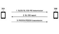
- FIG. 2 is a diagram illustrating an example (1) of a CSI report according to the embodiment of the present invention. It is assumed that QoS is managed in SL of NR. Therefore, it is assumed that SLSS and SL-CSI-RS (Reference @ Signal) are supported. SL-CSI-RS may be called SL-SRS (Sounding Reference Signal) or the like. It is also assumed that feedback in the PHY layer, MAC layer, and RRC layer is supported.
- the CSI may be reported to the base station device 10 or the user device 20.
- the CSI report includes RI (Rank Indicator), LI (Layer Indicator), wideband or sub-band CQI (Channel quality indicator), CRI (CSI-RS Resource Indicator), SSB (Synchronization signal block) index, SRI (Scheduling request indicator), other indexes associated with SS or RS, RSRP, RSRQ, RSSI (Received Signal Strength Indicator), and SNR (signal-to-noise ratio) may be included.
- RSRP, RSRQ, RSSI and SNR may be measured at unfiltered layer 1 or after a layer 3 filter is applied.
- the parameters included in the above CSI report are determined based on SL measurements.
- the measurement or report using the SLSS and SL-CSI-RS signals is set in the user device 20.
- the base station apparatus 10 or the user apparatus 20 Based on the report, the base station apparatus 10 or the user apparatus 20 performs at least one of MCS (Modulation and Coding Scheme), TBS (Transport and block size), rank or number of transmission layers, resource allocation, transmission power, and transmission timing. To determine.
- MCS Modulation and Coding Scheme
- TBS Transmission and block size
- rank or number of transmission layers resource allocation, transmission power, and transmission timing.
- step 1 the user device 20A transmits SLSS or SL-CSI-RS to the user device 20B.
- step 2 the user device 20B transmits an SL-CSI report to the base station device 10 based on the received SLSS or SL-CSI-RS measurement result.
- step 3 the base station apparatus 10 determines SL scheduling information of the user apparatus 20A based on the received SL-CSI report, and transmits the SL scheduling information to the user apparatus 20A via DCI as in Mode3.
- Step 4 the user device 20A transmits the PSCCH (Physical Sidelink Control Channel) or / and the PSSCH (Physical Sidelink Shared Channel) to the user device 20B based on the received SL scheduling information.
- PSCCH Physical Sidelink Control Channel
- / and the PSSCH Physical Sidelink Shared Channel
- the base station apparatus 10 can transmit the SL scheduling information determined based on the SL-CSI report including the measurement result of the SLSS or SL-CSI-RS to the user apparatus 20 via DCI.
- the base station device 10 shown in FIG. 2 may be replaced with a user device 20 having scheduling capability.
- the user device 20 having the scheduling capability is defined as an MCS (Modulation and Coding Scheme), a TBS (Transport block size), a rank or a transmission layer based on an instruction from the base station apparatus 10 or autonomously with respect to another user apparatus 20.
- the user apparatus 20 determines and notifies at least one of the number, resource allocation, transmission power, and transmission timing.
- the transmission of the SL scheduling information in step 3 may be performed via the SCI.
- FIG. 3 is a diagram illustrating an example (2) of a CSI report according to the embodiment of the present invention.
- a form of the SL-CSI report different from that in FIG. 2 will be described.
- step 1 the user device 20B transmits SLSS or SL-CSI-RS to the user device 20A.
- step 2 the user device 20A transmits an SL-CSI report to the base station device 10 based on the received SLSS or SL-CSI-RS measurement result.
- step 3 the base station apparatus 10 determines SL scheduling information of the user apparatus 20A based on the received SL-CSI report, and transmits the SL scheduling information to the user apparatus 20A via DCI as in Mode3.
- Step 4 the user device 20A transmits the PSCCH and / or PSSCH to the user device 20B based on the received SL scheduling information.
- Steps 2 and 3 may be omitted.
- the SL-CSI report transmitted from the user apparatus 20A to the base station apparatus 10 in Step 2 is, for example, a beam match (Beam correspondence) based on a result of receiving a signal from the user apparatus 20B by applying reception beamforming.
- Beam matching is also referred to as “Tx / Rx beam correspondence”, and a UE (User Equipment) capable of “beam matching” satisfies at least one of the following conditions 1) and 2).
- the following 1) and 2) are conditions when the device A and the device B perform communication, and correspond to a UE in which the device A can perform “beam matching”.
- the device A or the device B may be the user device 20 or the base station device 10.
- 1) Apparatus A can determine a transmission beam to be transmitted to apparatus B based on a measurement result of a signal received from apparatus B by applying one or a plurality of apparatus A-side reception beamforming.
- the device A can determine the reception beamforming for receiving the signal from the device B based on the notification from the device B including the measurement result of one or a plurality of device A-side transmission beams.
- the “beam matching” of the user device 20A satisfies at least the above condition 1).
- the base station apparatus 10 can transmit the SL scheduling information determined based on the SL-CSI report including the measurement result of the SLSS or SL-CSI-RS to the user apparatus 20 via DCI.
- the base station device 10 shown in FIG. 3 may be replaced with a user device 20 having scheduling capability.
- the transmission of the SL scheduling information in step 3 may be performed via the SCI.
- FIG. 4 is a diagram illustrating an example (3) of a CSI report according to the embodiment of the present invention.
- a mode in which the SL-CSI report is transmitted from the user device 20B to the user device 20A will be described.
- step 1 the user device 20A transmits SLSS or SL-CSI-RS to the user device 20B.
- step 2 the user device 20B transmits an SL-CSI report to the user device 20A based on the received SLSS or SL-CSI-RS measurement result.
- step 3 the user apparatus 20A autonomously determines SL scheduling information like Mode 4 based on the received SL-CSI report, and sets the PSCCH and / or PSSCH based on the SL scheduling information. Transmit to the user device 20B.
- the user device 20A can perform SL transmission to the user device 20B with SL scheduling information determined based on the SL-CSI report including the measurement result of the SLSS or SL-CSI-RS.
- FIG. 5 is a diagram for describing an example (1) of HARQ retransmission according to the embodiment of the present invention.
- ACK / NACK signaling to the base station apparatus 10 or the user apparatus 20 by HARQ may be supported.
- HARQ Hybrid automatic repeat request
- ACK / NACK is signaled to base station apparatus 10 or user apparatus 20.
- the base station apparatus 10 or the user apparatus 20 requests the transmitting user apparatus 20 to retransmit the PSCCH and / or the PSSCH.
- step 1 the user device 20A transmits the PSCCH and / or the PSSCH to the user device 20B.
- the user device 20A transmits SL-ACK / NACK signaling to the base station device 10 based on the received result of the received PSCCH and / or PSSCH.
- step 3 the base station apparatus 10 determines SL scheduling information for retransmission to the user apparatus 20A based on the received SL-ACK / NACK signaling, and transmits the SL scheduling information to the user apparatus 20A in Mode 3 Is transmitted via DCI as shown in FIG.
- step 4 the user device 20A retransmits the PSCCH and / or PSSCH to the user device 20B based on the received SL scheduling information for retransmission.
- the base station device 10 can transmit the SL scheduling information for retransmission determined based on SL-ACK / NACK signaling to the user device 20 via DCI.
- the base station device 10 shown in FIG. 5 may be replaced with a user device 20 having scheduling capability.
- the transmission of the SL scheduling information in step 3 may be performed via the SCI.
- FIG. 6 is a diagram illustrating an example (2) of HARQ retransmission according to the embodiment of the present invention.
- FIG. 6 a mode in which SL-ACK / NACK signaling is transmitted from user apparatus 20B to user apparatus 20A will be described.
- step 1 the user device 20A transmits the PSCCH and / or the PSSCH to the user device 20B.
- the user device 20B transmits SL-ACK / NACK signaling to the user device 20A based on the received result of the received PSCCH and / or PSSCH.
- Step 3 the user device 20A autonomously determines SL scheduling information for retransmission as in Mode 4 based on the received SL-ACK / NACK signaling, and based on the SL scheduling information, Retransmit the PSCCH and / or PSSCH to the user equipment 20B.
- the user apparatus 20A can execute retransmission of the SL to the user apparatus 20B with the SL scheduling information for retransmission determined based on the SL-ACK / NACK signaling.
- CSI or HARQ-ACK / NACK in SL is determined based on SL measurement results and transport block decoding results.
- the base station apparatus 10 or the user apparatus 20 determines the details of the SL scheduling information based on a report from the user apparatus 20 not performing the SL transmission or the user apparatus 20 performing the SL transmission.
- the user device 20 not performing the SL transmission corresponds to the user device 20B in FIG. 2, and the user device 20 performing the SL transmission corresponds to the user device 20A in FIG.
- Information other than CSI or HARQ-ACK / NACK for example, BSR (Buffer status report), PHR (Power head room), Tx / Rx timing, and the like are transmitted from the user device 20 via the UL similarly to FIG. 2 or FIG. It may be transmitted to the base station device 10.
- the TPC Transmit power control
- TA Timing Advance
- TCI Transmission Configuration Indicator
- SRI SRI
- indexes related to other beams are used to transmit DL from the base station apparatus 10 as in FIG. 2 or FIG. It may be transmitted to the user device 20 via the Internet.
- the structure of UCI (Uplink control information) in NR or related operations may be similarly used.
- the structure of the DCI in the NR or the related operation may be similarly used.
- the SL-CSI report or HARQ signaling described in FIGS. 2 to 6 may be similarly applied to transmission using another channel, for example, a Physical Side Link Broadcast Channel (PSBCH) or a Physical Side Link Discovery Channel (PSDCH).
- PSBCH Physical Side Link Broadcast Channel
- PSDCH Physical Side Link Discovery Channel
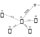
- FIG. 7 is a diagram illustrating an example (1) of an operation of the wireless communication system according to the embodiment of the present invention.
- the SL link ID may be added to the SL-CSI report and HARQ-ACK / NACK signaling and transmitted.
- the SL link ID may be explicitly notified by the ID of the destination UE and the ID of the source UE, or the ID associated with them.
- SL # 0, which is the SL link ID
- SL # 1 corresponds to the SL between the user device 20A and the user device 20B
- SL # 2 corresponds to the SL between the user device 20A and the user device 20D
- SL # 3 corresponds to the SL between the user device 20A and the user device 20C
- the user device 20A transmits the SL of the destination UE corresponding to the SL link ID.
- the ID and / or the ID of the source UE may be assigned and a report on the SL may be transmitted to the base station device 10.
- Part or all of the ID of the destination UE or the ID of the source UE may be derived from an RNTI (Radio Network Temporary Identifier) used for scrambling.
- RNTI Radio Network Temporary Identifier
- a group ID indicating a plurality of SL link IDs may be used as the SL link ID.
- the measurement / report ID may be used instead of or in addition to the SL link ID.
- the measurement / report ID may be given from the measurement settings or report settings for the SL.
- the measurement / report ID may be an ID in the RRC layer.
- an SS / RS resource ID may be used.
- the SS / RS resource ID is an ID associated with the resource to which the SS is transmitted or the resource to which the RS is transmitted.
- the SL link ID may be indexed by the user apparatus 20 performing the SL transmission and reported to the base station apparatus 10 or the user apparatus 20 performing the scheduling. .
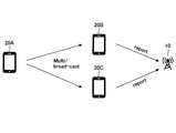
- FIG. 8 is a diagram illustrating an example (2) of an operation of the wireless communication system according to the embodiment of the present invention.
- the SL-CSI report or HARQ-ACK / NACK signaling may be performed by a plurality of user devices 20.
- the user device 20A multicasts or broadcasts the SLSS, SL-CSI-RS, PSCCH or PSSCH, and the user device 20B and the user device 20C receive.
- the user device 20B and the user device 20C may each execute the SL-CSI report to the base station device 10.
- the base station apparatus 10 may perform SL scheduling on the user apparatus 20A based on the received plurality of SL-CSI reports.
- the setting of the SL-CSI report or measurement may be set to be performed by a plurality of user devices 20.
- the setting of the SL-CSI report or measurement for the plurality of user devices 20 may be set via any of PBCH (Physical Broadcast Channel), PDCCH (Physical Downlink Control Channel) or PDSCH (Physical Downlink Shared Channel), It may be set via any signaling of the PHY layer, MAC layer or RRC layer.
- a group common RNTI group-common @ RNTI
- group-common @ RNTI may be used to identify multiple user devices 20.
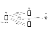
- FIG. 9 is a diagram illustrating an example (3) of an operation of the wireless communication system according to the embodiment of the present invention.
- the reported parameter of the SL-CSI report may be a value averaged in a plurality of SLs.
- the user device 20A performs multicast or broadcast of the SLSS, SL-CSI-RS, PSCCH or PSSCH, and the user device 20B and the user device 20C receive.
- the user device 20B and the user device 20C each execute an SL-CSI report to the user device 20A.
- the user apparatus 20A creates an SL-CSI report based on the result of averaging two or more values for each parameter included in the received plurality of SL-CSI reports, and reports the SL-CSI report to the base station apparatus 10. Good.
- the SL-CSI report transmitted by the user device 20A to the base station device 10 may include information indicating whether the report is an SL-CSI report corresponding to unicast or an SL-CSI report corresponding to broadcast. .
- the SL link ID corresponding to the unicast or the broadcast may be given an index from the user apparatus 20A that transmits the SL-CSI report to the base station apparatus 10.
- the user device 20A may execute the scheduling without reporting the SL-CSI to the base station device 10.
- the user apparatus 20 can transmit the SL-CSI report or the HARQ feedback of the SL to the base station apparatus 10 or another user apparatus 20. Based on the received SL-CSI report or HARQ feedback, the base station apparatus 10 or the user apparatus 20 having the scheduling capability can perform more accurate scheduling or scheduling for retransmission.
- the base station device 10 and the user device 20 include a function for implementing the above-described embodiment. However, each of the base station device 10 and the user device 20 may include only some of the functions in the embodiment.
- FIG. 10 is a diagram illustrating an example of a functional configuration of the base station device 10.
- base station apparatus 10 includes transmitting section 110, receiving section 120, setting section 130, and control section 140.
- the functional configuration shown in FIG. 10 is only an example. As long as the operation according to the embodiment of the present invention can be executed, the names of the functional divisions and the functional units may be any.
- the transmission unit 110 has a function of generating a signal to be transmitted to the user device 20 and transmitting the signal wirelessly.
- the receiving unit 120 includes a function of receiving various signals transmitted from the user device 20 and acquiring, for example, information of a higher layer from the received signals.
- transmitting section 110 has a function of transmitting NR-PSS, NR-SSS, NR-PBCH, DL / UL control signal, and the like to user apparatus 20. Further, for example, the transmitting unit 110 transmits information indicating that another terminal is approaching the user device 20, and the receiving unit 120 receives terminal information from the user device 20.
- the setting unit 130 stores in the storage device the setting information set in advance and various setting information to be transmitted to the user device 20, and reads out the setting information from the storage device as needed.
- the content of the setting information is, for example, information related to scheduling of D2D communication.
- control unit 140 performs the process related to the setting for the user device 20 to perform the D2D communication. Further, the control unit 140 performs processing related to scheduling of D2D communication according to the CSI report from the user device 20.
- a function unit related to signal transmission in control unit 140 may be included in transmission unit 110, and a function unit related to signal reception in control unit 140 may be included in reception unit 120.
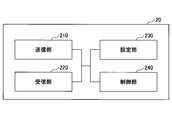
- FIG. 11 is a diagram illustrating an example of a functional configuration of the user device 20.
- the user device 20 includes a transmitting unit 210, a receiving unit 220, a setting unit 230, and a control unit 240.
- the functional configuration shown in FIG. 11 is only an example. As long as the operation according to the embodiment of the present invention can be executed, the names of the functional divisions and the functional units may be any.
- the transmission unit 210 creates a transmission signal from transmission data, and transmits the transmission signal wirelessly.
- the receiving unit 220 wirelessly receives various signals, and obtains a higher layer signal from the received physical layer signal.
- the receiving unit 220 has a function of receiving NR-PSS, NR-SSS, NR-PBCH, a DL / UL / SL control signal, and the like transmitted from the base station device 10.
- the transmitting unit 210 transmits the PSCCH (Physical Sidelink Shared Channel), the PSSCH (Physical Sidelink Shared Channel), the PSDCH (Physical Sidelink Discovery Channel), and the PSBCH (Physical Sidelink Broadcast Channel) to other user devices 20 as D2D communication. )
- the receiving unit 120 receives a PSCCH, a PSSCH, a PSDCH, a PSBCH, or the like from another user apparatus 20.
- the setting unit 230 stores various setting information received from the base station device 10 or the user device 20 by the receiving unit 220 in a storage device, and reads out the setting information from the storage device as needed.
- the setting unit 230 also stores preset setting information.
- the content of the setting information is, for example, information related to scheduling of D2D communication.
- the control unit 240 controls the D2D communication performed with another user device 20 as described in the embodiment. Further, the control unit 240 measures the quality of the D2D communication and reports the quality to the base station device 10 or another user device 20. In addition, the control unit 240 performs processing related to scheduling of D2D communication according to a CSI report from another user device 20.
- a function unit related to signal transmission in the control unit 240 may be included in the transmission unit 210, and a function unit related to signal reception in the control unit 240 may be included in the reception unit 220.
- each functional block may be realized by one device in which a plurality of elements are physically and / or logically combined, or two or more devices physically and / or logically separated from each other directly and directly. And / or indirectly (for example, wired and / or wireless), and may be implemented by these multiple devices.
- both the base station device 10 and the user device 20 according to an embodiment of the present invention may function as a computer that performs processing according to the embodiment of the present invention.
- FIG. 12 is a diagram illustrating an example of a hardware configuration of a wireless communication device that is the base station device 10 or the user device 20 according to the embodiment of the present invention.
- Each of the above-described base station apparatus 10 and user apparatus 20 is physically a computer device including a processor 1001, a storage device 1002, an auxiliary storage device 1003, a communication device 1004, an input device 1005, an output device 1006, a bus 1007, and the like. It may be configured.
- the term “apparatus” can be read as a circuit, a device, a unit, or the like.
- the hardware configuration of the base station device 10 and the user device 20 may be configured to include one or more devices indicated by 1001 to 1006 illustrated in the drawing, or may be configured without including some devices. May be done.
- the functions of the base station device 10 and the user device 20 are performed by reading predetermined software (program) on hardware such as the processor 1001 and the storage device 1002, so that the processor 1001 performs an arithmetic operation. This is realized by controlling reading and / or writing of data in the storage device 1002 and the auxiliary storage device 1003.
- the processor 1001 controls the entire computer by operating an operating system, for example.
- the processor 1001 may be configured by a central processing unit (CPU: Central Processing Unit) including an interface with a peripheral device, a control device, an arithmetic device, a register, and the like.
- CPU Central Processing Unit
- the processor 1001 reads out a program (program code), a software module, or data from the auxiliary storage device 1003 and / or the communication device 1004 to the storage device 1002, and executes various processes according to these.
- a program program that causes a computer to execute at least a part of the operation described in the above embodiment is used.
- the transmission unit 110, the reception unit 120, the setting unit 130, and the control unit 140 of the base station device 10 illustrated in FIG. 10 may be realized by a control program stored in the storage device 1002 and operated by the processor 1001. Further, for example, the transmission unit 210, the reception unit 220, the setting unit 230, and the control unit 240 of the user device 20 illustrated in FIG.
- Process 11 are realized by a control program stored in the storage device 1002 and operated by the processor 1001. Is also good. Although it has been described that the above-described various processes are executed by one processor 1001, the processes may be executed simultaneously or sequentially by two or more processors 1001. Processor 1001 may be implemented with one or more chips. Note that the program may be transmitted from a network via a telecommunication line.
- the storage device 1002 is a computer-readable recording medium and is, for example, at least one of a ROM (Read Only Memory), an EPROM (Erasable Programmable ROM), an EEPROM (Electrically Erasable Programmable ROM), and a RAM (Random Access Memory). It may be configured.
- the storage device 1002 may be called a register, a cache, a main memory (main storage device), or the like.
- the storage device 1002 can store a program (program code), a software module, and the like that can be executed to execute the processing according to an embodiment of the present invention.
- the auxiliary storage device 1003 is a computer-readable recording medium, for example, an optical disk such as a CD-ROM (Compact Disc), a hard disk drive, a flexible disk, a magneto-optical disk (for example, a compact disk, a digital versatile disk, Blu -Ray (registered trademark) disk), smart card, flash memory (eg, card, stick, key drive), floppy (registered trademark) disk, magnetic strip, or the like.
- the auxiliary storage device 1003 may be called an auxiliary storage device.
- the storage medium described above may be, for example, a database including the storage device 1002 and / or the auxiliary storage device 1003, a server, or any other suitable medium.
- the communication device 1004 is hardware (transmitting / receiving device) for performing communication between computers via a wired and / or wireless network, and is also referred to as, for example, a network device, a network controller, a network card, a communication module, and the like.
- the transmitting unit 110 and the receiving unit 120 of the base station device 10 may be realized by the communication device 1004.
- the transmission unit 210 and the reception unit 220 of the user device 20 may be realized by the communication device 1004.
- the input device 1005 is an input device (for example, a keyboard, a mouse, a microphone, a switch, a button, a sensor, and the like) that receives an external input.
- the output device 1006 is an output device that performs output to the outside (for example, a display, a speaker, an LED lamp, and the like). Note that the input device 1005 and the output device 1006 may have an integrated configuration (for example, a touch panel).
- the devices such as the processor 1001 and the storage device 1002 are connected by a bus 1007 for communicating information.
- the bus 1007 may be configured by a single bus, or may be configured by a different bus between devices.
- the base station device 10 and the user device 20 are respectively a microprocessor, a digital signal processor (DSP: Digital Signal Processor), an ASIC (Application Specific Integrated Circuit), a PLD (Programmable Logic Device), an FPGA (Field Programmable Gate Array), and the like. , And some or all of the functional blocks may be realized by the hardware.
- the processor 1001 may be implemented by at least one of these hardware.
- a user apparatus that communicates with a first user apparatus or a base station apparatus, and is used in a side link transmitted from the first user apparatus.
- a receiving unit that receives a synchronization signal or a reference signal to be received, a control unit that measures a channel state of a side link based on the synchronization signal or the reference signal, and information indicating the channel state of the side link,
- a user apparatus having a station apparatus or a transmission unit for transmitting to the first user apparatus.
- the user device 20 can transmit the SL-CSI report to the base station device 10 or another user device 20. Based on the received SL-CSI report, the base station apparatus 10 or the user apparatus 20 having the scheduling capability can perform more accurate scheduling or scheduling for retransmission. That is, in direct communication between terminals, communication quality can be appropriately controlled.
- the transmitting unit may transmit a side link channel to the first user apparatus.
- the user apparatus 20 that has received the side link synchronization signal or the reference signal transmits an SL-CSI report to the base station apparatus 10 or another user apparatus 20, and performs scheduling based on the SL-CSI report.
- the transmission efficiency of the own device can be improved.
- the transmitting unit transmits a synchronization signal or a reference signal used in a side link to a second user device
- the receiving unit receives information indicating a channel state of the side link from the second user device
- the control unit may determine scheduling information of a side link to be transmitted to the second user apparatus based on the received information indicating the channel state of the side link.
- the user device 20 can transmit the SL-CSI report to another user device 20.
- the user apparatus 20 having the scheduling capability can perform more accurate scheduling or scheduling for retransmission based on the received SL-CSI report.
- the receiving unit receives a side link channel from the first user apparatus, and transmits information indicating whether data included in the side link channel has been successfully decoded to the base station apparatus or the first user. It may be transmitted to the device.
- the user apparatus 20 can improve communication quality by applying HARQ feedback to SL.
- the transmitting unit transmits a synchronization signal or a reference signal used in a side link to a plurality of user devices
- the receiving unit receives information indicating a channel state of the side link from each of the plurality of user devices
- the control unit may transmit, to the base station apparatus, information indicating a channel state of the side link obtained by averaging parameters included in the received information indicating the channel states of the plurality of side links.
- the user apparatus 20 can transmit the SL-CSI report reflecting the channel state of the side link of the plurality of user apparatuses 20 to the base station apparatus 10.
- a base station apparatus for communicating with a user apparatus, wherein information indicating a channel state of the side link measured based on a synchronization signal or a reference signal used in the side link. And a control unit that determines scheduling information of the side link based on the information indicating the channel state of the side link, and a transmitting unit that transmits the scheduling information of the side link to the user device. Is provided.
- the user device 20 can transmit the SL-CSI report to the base station device 10 or another user device 20. Based on the received SL-CSI report, the base station apparatus 10 or the user apparatus 20 having the scheduling capability can perform more accurate scheduling or scheduling for retransmission. That is, in direct communication between terminals, communication quality can be appropriately controlled.
- the operations of a plurality of functional units may be physically performed by one component, or the operations of one functional unit may be physically performed by a plurality of components. In the processing procedure described in the embodiment, the order of the processing may be changed as long as there is no contradiction.
- the base station device 10 and the user device 20 have been described using a functional block diagram for convenience of processing description, such a device may be implemented by hardware, software, or a combination thereof.
- the software operated by the processor of the base station device 10 according to the embodiment of the present invention and the software operated by the processor of the user device 20 according to the embodiment of the present invention are a random access memory (RAM), a flash memory, and a read memory, respectively.
- the data may be stored in a dedicated memory (ROM), an EPROM, an EEPROM, a register, a hard disk (HDD), a removable disk, a CD-ROM, a database, a server, or any other suitable storage medium.
- the notification of information is not limited to the aspect / embodiment described in this specification, and may be performed by another method.
- the notification of information includes physical layer signaling (for example, DCI (Downlink Control Information), UCI (Uplink Control Information)), upper layer signaling (for example, RRC (Radio Resource Control) signaling, MAC (Medium Access Control) signaling, It may be implemented by broadcast information (MIB (Master Information Block), SIB (System Information Block)), other signals, or a combination thereof, and RRC signaling may be called an RRC message, for example, RRC message.
- a connection setup (RRC (Connection Setup) message, an RRC connection reconfiguration (RRC Connection Reconfiguration) message, or the like may be used.
- Each aspect / embodiment described in this specification includes LTE (Long Term Evolution), LTE-A (LTE-Advanced), SUPER 3G, IMT-Advanced, 4G, 5G, FRA (Future Radio Access), W-CDMA.
- LTE Long Term Evolution
- LTE-A Long Term Evolution-Advanced
- SUPER 3G IMT-Advanced
- 4G 5G
- FRA Full Radio Access
- W-CDMA Wideband
- GSM registered trademark
- CDMA2000 Code Division Multiple Access 2000
- UMB User Mobile Broadband
- IEEE 802.11 Wi-Fi
- IEEE 802.16 WiMAX
- IEEE 802.20 UWB (Ultra-WideBand
- the present invention may be applied to a system using Bluetooth (registered trademark), another appropriate system, and / or a next-generation system extended based on the system.
- the specific operation described as being performed by the base station apparatus 10 in this specification may be performed by an upper node (upper @ node) in some cases.
- an upper node upper @ node
- various operations performed for communication with the user device 20 are different from the base station device 10 and / or the base station device 10. It should be clear that this can be done by other network nodes (for example, but not limited to MME or S-GW etc.).
- MME Mobility Management Entity
- the user equipment 20 may be provided by one of ordinary skill in the art to a subscriber station, mobile unit, subscriber unit, wireless unit, remote unit, mobile device, wireless device, wireless communication device, remote device, mobile subscriber station, access terminal, mobile terminal, It may also be called a wireless terminal, a remote terminal, a handset, a user agent, a mobile client, a client, or some other suitable term.
- Base station device 10 may also be referred to by those skilled in the art as NB (NodeB), eNB (evolved NodeB), gNB, Base Station (Base Station), or some other suitable terminology.
- NB NodeB
- eNB evolved NodeB
- gNB Base Station
- Base Station Base Station
- determining may encompass a wide variety of actions.
- the “judgment” and “decision” are, for example, judgment (judging), calculation (computing), processing (processing), deriving (investigating), investigating (looking up) (for example, table , A search in a database or another data structure), ascertaining a thing as “determining", “determining", and the like.
- “determining” and “determining” include receiving (eg, receiving information), transmitting (eg, transmitting information), input (input), output (output), and accessing. (Accessing) (for example, accessing data in a memory) may be regarded as “determined” or “determined”.
- judgment and “decision” mean that resolving, selecting, selecting, establishing, establishing, comparing, etc. are regarded as “judgment” and “determined”. May be included. That is, “judgment” and “decision” may include deeming any operation as “judgment” and “determined”.
- SLSS or SL-CSI-RS is an example of a synchronization signal or a reference signal used in a side link.
- the SL-CSI report is an example of information indicating a channel state of a side link.
- HARQ-ACK / NACK signaling is an example of information indicating whether data has been successfully decoded.
- the destination UE is an example of a destination UE.
- the source UE is an example of a source UE.
Landscapes
- Engineering & Computer Science (AREA)
- Signal Processing (AREA)
- Computer Networks & Wireless Communication (AREA)
- Quality & Reliability (AREA)
- Mobile Radio Communication Systems (AREA)
Abstract
ユーザ装置は、第1のユーザ装置又は基地局装置と通信を行うユーザ装置であって、前記第1のユーザ装置から送信されるサイドリンクで使用される同期信号又は参照信号を受信する受信部と、前記同期信号又は前記参照信号に基づいて、サイドリンクのチャネル状態を測定する制御部と、前記サイドリンクのチャネル状態を示す情報を、前記基地局装置又は前記第1のユーザ装置に送信する送信部とを有する。
Description
本発明は、無線通信システムにおけるユーザ装置及び基地局装置に関する。
LTE(Long Term Evolution)及びLTEの後継システム(例えば、LTE-A(LTE Advanced)、NR(New Radio)(5Gともいう。))では、ユーザ装置同士が無線基地局を介さないで直接通信を行うD2D(Device to Device)技術が検討されている(例えば非特許文献1)。
D2Dは、ユーザ装置と基地局装置との間のトラフィックを軽減し、災害時等に基地局装置が通信不能になった場合でもユーザ装置間の通信を可能とする。なお、3GPP(3rd Generation Partnership Project)では、D2Dを「サイドリンク(sidelink)」と称しているが、本明細書では、より一般的な用語であるD2Dを使用する。ただし、後述する実施の形態の説明では必要に応じてサイドリンクも使用する。
D2Dは、通信可能な他のユーザ装置を発見するためのD2Dディスカバリ(D2D discovery、D2D発見ともいう。)と、ユーザ装置間で直接通信するためのD2Dコミュニケーション(D2D direct communication、D2D通信、端末間直接通信等ともいう。)と、に大別される。以下では、D2Dコミュニケーション、D2Dディスカバリ等を特に区別しないときは、単にD2Dと呼ぶ。また、D2Dで送受信される信号を、D2D信号と呼ぶ。NRにおけるV2X(Vehicle to Everything)に係るサービスの様々なユースケースが検討されている(例えば非特許文献2)。
3GPP TS 36.211 V15.1.0(2018-03)
3GPP TR 22.886 V15.1.0(2017-03)
D2D通信において、QoS(Quality of service)を管理する場合、D2D通信の品質を測定して送信側ユーザ装置に適切なフィードバックを行うことが要求される。しかしながら、従来のD2D通信においては、測定結果のフィードバックはサポートされていなかった。
本発明は上記の点に鑑みてなされたものであり、端末間直接通信において、通信品質を適切に制御することを目的とする。
開示の技術によれば、第1のユーザ装置又は基地局装置と通信を行うユーザ装置であって、前記第1のユーザ装置から送信されるサイドリンクで使用される同期信号又は参照信号を受信する受信部と、前記同期信号又は前記参照信号に基づいて、サイドリンクのチャネル状態を測定する制御部と、前記サイドリンクのチャネル状態を示す情報を、前記基地局装置又は前記第1のユーザ装置に送信する送信部とを有するユーザ装置が提供される。
開示の技術によれば、端末間直接通信において、通信品質を適切に制御することができる。
以下、図面を参照して本発明の実施の形態を説明する。なお、以下で説明する実施の形態は一例であり、本発明が適用される実施の形態は、以下の実施の形態に限られない。
本発明の実施の形態の無線通信システムの動作にあたっては、適宜、既存技術が使用される。ただし、当該既存技術は、例えば既存のLTEであるが、既存のLTEに限られない。また、本明細書で使用する用語「LTE」は、特に断らない限り、LTE-Advanced、及び、LTE-Advanced以降の方式(例:NR)を含む広い意味を有するものとする。
また、本発明の実施の形態において、複信(Duplex)方式は、TDD(Time Division Duplex)方式でもよいし、FDD(Frequency Division Duplex)方式でもよいし、又はそれ以外(例えば、Flexible Duplex等)の方式でもよい。
また、以下の説明において、送信ビームを用いて信号を送信する方法は、プリコーディングベクトルが乗算された(プリコーディングベクトルでプリコードされた)信号を送信するデジタルビームフォーミングであってもよいし、RF(Radio Frequency)回路内の可変移相器を用いてビームフォーミングを実現するアナログビームフォーミングであってもよい。同様に、受信ビームを用いて信号を受信する方法は、所定の重みベクトルを受信した信号に乗算するデジタルビームフォーミングであってもよいし、RF回路内の可変位相器を用いてビームフォーミングを実現するアナログビームフォーミングであってもよい。デジタルビームフォーミングとアナログビームフォーミングを組み合わせたハイブリッドビームフォーミングが適用されてもよい。また、送信ビームを用いて信号を送信することは、特定のアンテナポートで信号を送信することであってもよい。同様に、受信ビームを用いて信号を受信することは、特定のアンテナポートで信号を受信することとであってもよい。アンテナポートとは、3GPPの規格で定義されている論理アンテナポート又は物理アンテナポートを指す。また、上記プリコーディング又はビームフォーミングは、プリコーダ又は空間領域フィルタ(Spatial domain filter)等と呼ばれてもよい。
なお、送信ビーム及び受信ビームの形成方法は、上記の方法に限られない。例えば、複数アンテナを備える基地局装置10又はユーザ装置20において、それぞれのアンテナの角度を変える方法を用いてもよいし、プリコーディングベクトルを用いる方法とアンテナの角度を変える方法を組み合わせる方法を用いてもよいし、異なるアンテナパネルを切り替えて利用してもよいし、複数のアンテナパネルを合わせて使う方法を組み合わせる方法を用いてもよいし、その他の方法を用いてもよい。また、例えば、高周波数帯において、複数の互いに異なる送信ビームが使用されてもよい。複数の送信ビームが使用されることを、マルチビーム運用といい、ひとつの送信ビームが使用されることを、シングルビーム運用という。
また、本発明の実施の形態において、無線パラメータ等が「設定される(Configure)」とは、所定の値が予め設定(Pre-configure)されることであってもよいし、基地局装置10又はユーザ装置20から通知される無線パラメータが設定されることであってもよい。
図1は、V2Xを説明するための図である。3GPPでは、D2D機能を拡張することでV2X(Vehicle to Everything)あるいはeV2X(enhanced V2X)を実現することが検討され、仕様化が進められている。図1に示されるように、V2Xとは、ITS(Intelligent Transport Systems)の一部であり、自動車間で行われる通信形態を意味するV2V(Vehicle to Vehicle)、自動車と道路脇に設置される路側機(RSU:Road-Side Unit)との間で行われる通信形態を意味するV2I(Vehicle to Infrastructure)、自動車とドライバが所持するモバイル端末との間で行われる通信形態を意味するV2N(Vehicle to Nomadic device)、及び、自動車と歩行者が所持するモバイル端末との間で行われる通信形態を意味するV2P(Vehicle to Pedestrian)の総称である。
また、3GPPにおいて、LTE又はNRのセルラ通信及び端末間通信を用いたV2Xが検討されている。LTE又はNRのV2Xについて、今後3GPP仕様に限られない検討も進められることが想定される。例えば、インターオペラビリティの確保、上位レイヤの実装によるコストの低減、複数RAT(Radio Access Technology)の併用又は切替方法、各国におけるレギュレーション対応、LTE又はNRのV2Xプラットフォームのデータ取得、配信、データベース管理及び利用方法が検討されることが想定される。
本発明の実施の形態において、通信装置が車両に搭載される形態を主に想定するが、本発明の実施の形態は、当該形態に限定されない。例えば、通信装置は人が保持する端末であってもよいし、通信装置がドローンあるいは航空機に搭載される装置であってもよいし、通信装置が基地局、RSU、中継局(リレーノード)等であってもよい。
なお、SL(Sidelink)は、UL(Uplink)又はDL(Downlink)と以下1)-4)のいずれか又は組み合わせに基づいて区別されてもよい。また、SLは、他の名称であってもよい。
1)時間領域のリソース配置
2)周波数領域のリソース配置
3)参照する同期信号(SLSS(Sidelink Synchronization Signal)を含む)
4)送信電力制御のためのパスロス測定に用いる参照信号
1)時間領域のリソース配置
2)周波数領域のリソース配置
3)参照する同期信号(SLSS(Sidelink Synchronization Signal)を含む)
4)送信電力制御のためのパスロス測定に用いる参照信号
LTEのSLにおいて、ユーザ装置20へのSLのリソース割り当てに関してMode3とMode4が規定されている。Mode3では、基地局装置10からユーザ装置20に送信されるDCI(Downlink Control Information)によりダイナミックに送信リソースが割り当てられる。また、Mode3ではSPS(Semi Persistent Scheduling)も可能である。Mode4では、ユーザ装置20はリソースプールから自律的に送信リソースを選択する。
また、LTEのSLにおいて、SLSSがサポートされる。一方、LTEのSLにおいて、PHY(Physical)レイヤ、MAC(Media Access Control)レイヤ、RRC(Radio Resource Control)レイヤにおけるフィードバックはサポートされていなかった。すなわち、レイヤ1のRSRP(Reference Signals Received Power)又はRSRQ(Reference Signal Received Quality)の報告、CSI(Channel State Information)の報告はサポートされていなかった。
図2は、本発明の実施の形態におけるCSI報告の例(1)を説明するための図である。NRのSLにおいて、QoSが管理されることが想定される。そのため、SLSS及びSL-CSI-RS(Reference Signal)がサポートされることが想定される。SL-CSI-RSはSL-SRS(Sounding Reference Signal)等と呼ばれてもよい。また、PHYレイヤ、MACレイヤ、RRCレイヤにおけるフィードバックがサポートされることが想定される。
そこで、SL送信において、基地局装置10又はユーザ装置20にCSIの報告が行われてもよい。CSIの報告には、RI(Rank Indicator)、LI(Layer Indicator)、ワイドバンド又はサブバンドCQI(Channel quality indicator)、CRI(CSI-RS Resource Indicator)、SSB(Synchronization signal block)インデックス、SRI(Scheduling request indicator)、その他のSS又はRSに関連付けられるインデックス、RSRP、RSRQ、RSSI(Received Signal Strength Indicator)、SNR(signal-to-noise ratio)が含まれてもよい。RSRP、RSRQ、RSSI及びSNRは、フィルタされていないレイヤ1で測定されてもよいし、レイヤ3フィルタが適用された後に測定されてもよい。
上記のCSIの報告に含まれるパラメータは、SL測定に基づいて決定される。SLSS、SL-CSI-RSの信号を使用した測定又は報告が、ユーザ装置20に設定される。当該報告に基づいて、基地局装置10又はユーザ装置20は、MCS(Modulation and Coding Scheme)、TBS(Transport block size)、ランク又は送信レイヤ数、リソース配置、送信電力、送信タイミングのうち少なくとも1つを決定する。
図2に示されるように、ステップ1において、ユーザ装置20Aは、SLSS又はSL-CSI-RSをユーザ装置20Bに送信する。続いて、ステップ2において、ユーザ装置20Bは、受信したSLSS又はSL-CSI-RSの測定結果に基づいて、SL-CSI報告を基地局装置10に送信する。続いて、ステップ3において、基地局装置10は、受信したSL-CSI報告に基づいて、ユーザ装置20AのSLスケジューリング情報を決定し、当該SLスケジューリング情報をユーザ装置20AにMode3のようにDCIを介して送信する。続いて、ステップ4において、ユーザ装置20Aは、受信したSLスケジューリング情報に基づいて、PSCCH(Physical Sidelink Control Channel)又は/及びPSSCH(Physical Sidelink Shared Channel)をユーザ装置20Bに送信する。
上記のように、基地局装置10は、SLSS又はSL-CSI-RSの測定結果を含むSL-CSI報告に基づいて決定したSLスケジューリング情報を、DCIを介してユーザ装置20に送信することができる。なお、図2に示される基地局装置10は、スケジューリング能力を有するユーザ装置20に置換されてもよい。スケジューリング能力を有するユーザ装置20とは、基地局装置10からの指示に基づき又は自律的に他のユーザ装置20に対し、MCS(Modulation and Coding Scheme)、TBS(Transport block size)、ランク又は送信レイヤ数、リソース配置、送信電力、送信タイミングのうち少なくとも1つを決定し、通知するユーザ装置20である。図2において基地局装置10がユーザ装置20に置換された場合、ステップ3のSLスケジューリング情報の送信はSCIを介して行われてもよい。
図3は、本発明の実施の形態におけるCSI報告の例(2)を説明するための図である。図3において、図2と異なるSL-CSI報告の形態を説明する。
図3に示されるように、ステップ1において、ユーザ装置20Bは、SLSS又はSL-CSI-RSをユーザ装置20Aに送信する。続いて、ステップ2において、ユーザ装置20Aは、受信したSLSS又はSL-CSI-RSの測定結果に基づいて、SL-CSI報告を基地局装置10に送信する。続いて、ステップ3において、基地局装置10は、受信したSL-CSI報告に基づいて、ユーザ装置20AのSLスケジューリング情報を決定し、当該SLスケジューリング情報をユーザ装置20AにMode3のようにDCIを介して送信する。続いて、ステップ4において、ユーザ装置20Aは、受信したSLスケジューリング情報に基づいて、PSCCH又は/及びPSSCHをユーザ装置20Bに送信する。ユーザ装置20AがSLSS又はSL-CSI-RSの測定値に基づいて、Mode4のように自律的にSLスケジューリング情報を決定する場合、ステップ2及びステップ3は省略されてもよい。
ここで、ステップ2においてユーザ装置20Aから基地局装置10に送信されるSL-CSI報告は、例えば、ユーザ装置20Bから信号を、受信ビームフォーミングを適用して受信した結果からビーム一致(Beam correspondence)によって算出されたユーザ装置20Aからユーザ装置20Bに送信するチャネルの状態を示す情報を含んでもよい。
「ビーム一致」は、「Tx/Rx beam correspondence」ともいい、「ビーム一致」が可能であるUE(User Equipment)とは、下記の1)2)の条件の少なくともひとつを満たすものとする。下記の1)2)は、装置Aと装置Bとが通信を行う場合の条件であり、装置Aが「ビーム一致」が可能であるUEに対応する。装置A又は装置Bは、ユーザ装置20であってもよいし基地局装置10であってもよい。
1)装置Aは、1又は複数の装置A側受信ビームフォーミングを適用して装置Bから受信した信号の測定結果に基づいて、装置Bに送信するための送信ビームを決定することができる。
2)装置Aは、1又は複数の装置A側送信ビームの測定結果を含む装置Bからの通知に基づいて、装置Bからの信号を受信するための受信ビームフォーミングを決定することができる。
図3においては、ユーザ装置20Aの「ビーム一致」は少なくとも上記1)の条件が満たされるものとする。
1)装置Aは、1又は複数の装置A側受信ビームフォーミングを適用して装置Bから受信した信号の測定結果に基づいて、装置Bに送信するための送信ビームを決定することができる。
2)装置Aは、1又は複数の装置A側送信ビームの測定結果を含む装置Bからの通知に基づいて、装置Bからの信号を受信するための受信ビームフォーミングを決定することができる。
図3においては、ユーザ装置20Aの「ビーム一致」は少なくとも上記1)の条件が満たされるものとする。
上記のように、基地局装置10は、SLSS又はSL-CSI-RSの測定結果を含むSL-CSI報告に基づいて決定したSLスケジューリング情報を、DCIを介してユーザ装置20に送信することができる。なお、図3に示される基地局装置10は、スケジューリング能力を有するユーザ装置20に置換されてもよい。図3において基地局装置10がユーザ装置20に置換された場合、ステップ3のSLスケジューリング情報の送信はSCIを介して行われてもよい。
図4は、本発明の実施の形態におけるCSI報告の例(3)を説明するための図である。図4において、SL-CSI報告がユーザ装置20Bからユーザ装置20Aに送信される形態を説明する。
図4に示されるように、ステップ1において、ユーザ装置20Aは、SLSS又はSL-CSI-RSをユーザ装置20Bに送信する。続いて、ステップ2において、ユーザ装置20Bは、受信したSLSS又はSL-CSI-RSの測定結果に基づいて、SL-CSI報告をユーザ装置20Aに送信する。続いて、ステップ3において、ユーザ装置20Aは、受信したSL-CSI報告に基づいて、Mode4のように自律的にSLスケジューリング情報を決定し、当該SLスケジューリング情報に基づいて、PSCCH又は/及びPSSCHをユーザ装置20Bに送信する。
上記のように、ユーザ装置20Aは、SLSS又はSL-CSI-RSの測定結果を含むSL-CSI報告に基づいて決定したSLスケジューリング情報で、ユーザ装置20BにSL送信することができる。
図5は、本発明の実施の形態におけるHARQ再送の例(1)を説明するための図である。SL送信において、HARQ(Hybrid automatic repeat request)による基地局装置10又はユーザ装置20へのACK/NACKシグナリングがサポートされてもよい。SL送信において、ACK/NACKが基地局装置10又はユーザ装置20にシグナリングされる。NACKが受信された場合、基地局装置10又はユーザ装置20は、送信したユーザ装置20にPSCCH又は/及びPSSCHの再送を要求する。
図5に示されるように、ステップ1において、ユーザ装置20Aは、PSCCH又は/及びPSSCHをユーザ装置20Bに送信する。続いて、ステップ2において、ユーザ装置20Aは、受信したPSCCH又は/及びPSSCHの受信結果に基づいて、SL-ACK/NACKシグナリングを基地局装置10に送信する。続いて、ステップ3において、基地局装置10は、受信したSL-ACK/NACKシグナリングに基づいて、ユーザ装置20Aに再送のためのSLスケジューリング情報を決定し、当該SLスケジューリング情報をユーザ装置20AにMode3のようにDCIを介して送信する。続いて、ステップ4において、ユーザ装置20Aは、受信した再送のためのSLスケジューリング情報に基づいて、PSCCH又は/及びPSSCHをユーザ装置20Bに再送する。
上記のように、基地局装置10は、SL-ACK/NACKシグナリングに基づいて決定した再送のためのSLスケジューリング情報を、DCIを介してユーザ装置20に送信することができる。なお、図5に示される基地局装置10は、スケジューリング能力を有するユーザ装置20に置換されてもよい。図5において基地局装置10がユーザ装置20に置換された場合、ステップ3のSLスケジューリング情報の送信はSCIを介して行われてもよい。
図6は、本発明の実施の形態におけるHARQ再送の例(2)を説明するための図である。図6において、SL-ACK/NACKシグナリングがユーザ装置20Bからユーザ装置20Aに送信される形態を説明する。
図6に示されるように、ステップ1において、ユーザ装置20Aは、PSCCH又は/及びPSSCHをユーザ装置20Bに送信する。続いて、ステップ2において、ユーザ装置20Bは、受信したPSCCH又は/及びPSSCHの受信結果に基づいて、SL-ACK/NACKシグナリングをユーザ装置20Aに送信する。続いて、ステップ3において、ユーザ装置20Aは、受信したSL-ACK/NACKシグナリングに基づいて、Mode4のように自律的に再送のためのSLスケジューリング情報を決定し、当該SLスケジューリング情報に基づいて、PSCCH又は/及びPSSCHをユーザ装置20Bに再送する。
上記のように、ユーザ装置20Aは、SL-ACK/NACKシグナリングに基づいて決定した再送のためのSLスケジューリング情報で、ユーザ装置20BにSLの再送を実行することができる。
図2から図6で説明したように、SLにおけるCSI又はHARQ-ACK/NACKは、SL測定結果及びトランスポートブロックの復号結果に基づいて決定される。基地局装置10又はユーザ装置20は、SL送信していないユーザ装置20又はSL送信しているユーザ装置20からの報告に基づいて、SLスケジューリング情報の詳細を決定する。SL送信していないユーザ装置20とは、図2のユーザ装置20Bに対応し、SL送信しているユーザ装置20とは、図3のユーザ装置20Aに対応する。
CSI又はHARQ-ACK/NACK以外の情報、例えば、BSR(Buffer status report)、PHR(Power head room)、Tx/Rxタイミング等が、図2又は図3と同様にユーザ装置20からULを介して基地局装置10に送信されてもよい。また、TPC(Transmit power control)コマンド、TA(Timing Advance)コマンド、TCI(Transmission Configuration Indicator)、SRI、他のビームに関連するインデックスが、図2又は図3と同様に基地局装置10からDLを介してユーザ装置20に送信されてもよい。
図2から図6で説明したユーザ装置20又は基地局装置10の動作において、NRにおけるUCI(Uplink control information)の構造又は関連する動作が同様に使用されてもよい。図2から図6で説明した基地局装置10又はユーザ装置20の動作において、NRにおけるDCIの構造又は関連する動作が同様に使用されてもよい。図2から図6で説明したSL-CSI報告又はHARQシグナリングは、他のチャネル、例えばPSBCH(Physical Sidelink Broadcast Channel)又はPSDCH(Physical Sidelink Discovery Channel)を使用する送信において同様に適用されてもよい。
図7は、本発明の実施の形態における無線通信システムの動作の例(1)を説明するための図である。基地局装置10又はスケジューリングを行うユーザ装置20にSLに係る報告が送信されるとき、SLリンクIDがSL-CSI報告及びHARQ-ACK/NACKシグナリングに付与されて送信されてもよい。
SLリンクIDは、デスティネーションUEのIDとソースUEのID又はそれらに紐づけられたIDによって、明示的に通知されてもよい。図7に示される例では、SLリンクIDであるSL#0はユーザ装置20Aとユーザ装置20EとのSLに対応し、SL#1はユーザ装置20Aとユーザ装置20BとのSLに対応し、SL#2はユーザ装置20Aとユーザ装置20DとのSLに対応し、SL#3はユーザ装置20Aとユーザ装置20CとのSLに対応し、ユーザ装置20Aは、SLリンクIDに対応するデスティネーションUEのID及び/又はソースUEのIDを付与してSLに係る報告を基地局装置10に送信してもよい。
デスティネーションUEのID又はソースUEのIDの一部又は全部は、スクランブルに使用するRNTI(Radio Network Temporary Identifier)から派生してもよい。SLリンクIDとして、複数のSLリンクIDを示すグループIDが使用されてもよい。
SLリンクIDに代えて又は追加して、測定/報告IDが使用されてもよい。測定/報告IDは、SLに係る測定の設定又は報告の設定から与えられてもよい。測定/報告IDは、RRCレイヤにおけるIDであってもよい。さらに、SS/RSリソースIDが使用されてもよい。SS/RSリソースIDは、SSが送信されるリソース又はRSが送信されるリソースに関連付けられるIDである。
SL送信を行うユーザ装置20が報告を実行する場合、SLリンクIDは、SL送信を行うユーザ装置20によってインデックスが付与されて、基地局装置10又はスケジューリングを行うユーザ装置20に報告されてもよい。
図8は、本発明の実施の形態における無線通信システムの動作の例(2)を説明するための図である。SL-CSI報告又はHARQ-ACK/NACKシグナリングは、複数のユーザ装置20によって実行されてもよい。
図8に示されるように、ユーザ装置20AがSLSS、SL-CSI-RS、PSCCH又はPSSCHのマルチキャスト又はブロードキャストを行い、ユーザ装置20B及びユーザ装置20Cが受信する。ユーザ装置20B及びユーザ装置20Cは、それぞれSL-CSI報告を基地局装置10に実行してもよい。基地局装置10は、受信した複数のSL-CSI報告に基づいて、ユーザ装置20AにSLスケジューリングを行ってもよい。
SL-CSI報告又は測定の設定は、複数のユーザ装置20が実行するように設定されてもよい。複数のユーザ装置20に対するSL-CSI報告又は測定の設定は、PBCH(Physical Broadcast Channel)、PDCCH(Physical Downlink Control Channel)又はPDSCH(Physical Downlink Shared Channel)のいずれを介して設定されてもよいし、PHYレイヤ、MACレイヤ又はRRCレイヤのいずれのシグナリングを介して設定されてもよい。PDCCHを介して設定される場合、グループ共通RNTI(group-common RNTI)が複数のユーザ装置20を特定するために使用されてもよい。
図9は、本発明の実施の形態における無線通信システムの動作の例(3)を説明するための図である。SLを送信するユーザ装置20が、マルチキャスト又はブロードキャストを実行するとき、報告されるSL-CSI報告のパラメータは、複数のSLにおいて平均化された値であってもよい。
図9に示されるように、ユーザ装置20AがSLSS、SL-CSI-RS、PSCCH又はPSSCHのマルチキャスト又はブロードキャストを行い、ユーザ装置20B及びユーザ装置20Cが受信する。ユーザ装置20B及びユーザ装置20Cは、それぞれユーザ装置20AにSL-CSI報告を実行する。ユーザ装置20Aは、受信した複数のSL-CSI報告に含まれる各パラメータについて、2つ以上の値を平均化した結果に基づいてSL-CSI報告を作成し、基地局装置10に報告してもよい。
ユーザ装置20Aが、基地局装置10に送信するSL-CSI報告に、ユニキャストに対応するSL-CSI報告であるかブロードキャストに対応するSL-CSI報告であるかを示す情報が含まれてもよい。
ユニキャスト又はブロードキャストに対応するSLリンクIDは、基地局装置10にSL-CSI報告を送信するユーザ装置20Aから、インデックスを付与されてもよい。
なお、ユーザ装置20Aがスケジューリング能力を有する場合、基地局装置10にSL-CSI報告をせずに、ユーザ装置20Aがスケジューリングを実行してもよい。
上述の実施例により、ユーザ装置20は、SL-CSI報告又はSLのHARQフィードバックを基地局装置10又は他のユーザ装置20に送信することができる。基地局装置10又はスケジューリング能力を有するユーザ装置20は、受信したSL-CSI報告又はHARQフィードバックに基づいて、より正確なスケジューリング又は再送のためのスケジューリングが可能となる。
すなわち、端末間直接通信において、通信品質を適切に制御することができる。
(装置構成)
次に、これまでに説明した処理及び動作を実行する基地局装置10及びユーザ装置20の機能構成例を説明する。基地局装置10及びユーザ装置20は上述した実施例を実施する機能を含む。ただし、基地局装置10及びユーザ装置20はそれぞれ、実施例の中の一部の機能のみを備えることとしてもよい。
次に、これまでに説明した処理及び動作を実行する基地局装置10及びユーザ装置20の機能構成例を説明する。基地局装置10及びユーザ装置20は上述した実施例を実施する機能を含む。ただし、基地局装置10及びユーザ装置20はそれぞれ、実施例の中の一部の機能のみを備えることとしてもよい。
<基地局装置10>
図10は、基地局装置10の機能構成の一例を示す図である。図10に示されるように、基地局装置10は、送信部110と、受信部120と、設定部130と、制御部140とを有する。図10に示される機能構成は一例に過ぎない。本発明の実施の形態に係る動作を実行できるのであれば、機能区分及び機能部の名称はどのようなものでもよい。
図10は、基地局装置10の機能構成の一例を示す図である。図10に示されるように、基地局装置10は、送信部110と、受信部120と、設定部130と、制御部140とを有する。図10に示される機能構成は一例に過ぎない。本発明の実施の形態に係る動作を実行できるのであれば、機能区分及び機能部の名称はどのようなものでもよい。
送信部110は、ユーザ装置20側に送信する信号を生成し、当該信号を無線で送信する機能を含む。受信部120は、ユーザ装置20から送信された各種の信号を受信し、受信した信号から、例えばより上位のレイヤの情報を取得する機能を含む。また、送信部110は、ユーザ装置20へNR-PSS、NR-SSS、NR-PBCH、DL/UL制御信号等を送信する機能を有する。また、例えば、送信部110は、ユーザ装置20に他端末が近接していることを示す情報を送信し、受信部120は、ユーザ装置20から端末情報を受信する。
設定部130は、予め設定される設定情報、及び、ユーザ装置20に送信する各種の設定情報を記憶装置に格納し、必要に応じて記憶装置から読み出す。設定情報の内容は、例えば、D2D通信のスケジューリングに係る情報等である。
制御部140は、実施例において説明したように、ユーザ装置20がD2D通信を行うための設定に係る処理を行う。また、制御部140は、ユーザ装置20からのCSI報告に応じたD2D通信のスケジューリングに係る処理を行う。制御部140における信号送信に関する機能部を送信部110に含め、制御部140における信号受信に関する機能部を受信部120に含めてもよい。
<ユーザ装置20>
図11は、ユーザ装置20の機能構成の一例を示す図である。図11に示されるように、ユーザ装置20は、送信部210と、受信部220と、設定部230と、制御部240とを有する。図11に示される機能構成は一例に過ぎない。本発明の実施の形態に係る動作を実行できるのであれば、機能区分及び機能部の名称はどのようなものでもよい。
図11は、ユーザ装置20の機能構成の一例を示す図である。図11に示されるように、ユーザ装置20は、送信部210と、受信部220と、設定部230と、制御部240とを有する。図11に示される機能構成は一例に過ぎない。本発明の実施の形態に係る動作を実行できるのであれば、機能区分及び機能部の名称はどのようなものでもよい。
送信部210は、送信データから送信信号を作成し、当該送信信号を無線で送信する。受信部220は、各種の信号を無線受信し、受信した物理レイヤの信号からより上位のレイヤの信号を取得する。また、受信部220は、基地局装置10から送信されるNR-PSS、NR-SSS、NR-PBCH、DL/UL/SL制御信号等を受信する機能を有する。また、例えば、送信部210は、D2D通信として、他のユーザ装置20に、PSCCH(Physical Sidelink Control Channel)、PSSCH(Physical Sidelink Shared Channel)、PSDCH(Physical Sidelink Discovery Channel)、PSBCH(Physical Sidelink Broadcast Channel)等を送信し、受信部120は、他のユーザ装置20から、PSCCH、PSSCH、PSDCH又はPSBCH等を受信する。
設定部230は、受信部220により基地局装置10又はユーザ装置20から受信した各種の設定情報を記憶装置に格納し、必要に応じて記憶装置から読み出す。また、設定部230は、予め設定される設定情報も格納する。設定情報の内容は、例えば、D2D通信のスケジューリングに係る情報等である。
制御部240は、実施例において説明したように、他のユーザ装置20と実行されるD2D通信を制御する。また、制御部240は、D2D通信の品質を測定し基地局装置10又は他のユーザ装置20に報告する。また、制御部240は、制御部140は、他のユーザ装置20からのCSI報告に応じたD2D通信のスケジューリングに係る処理を行う。制御部240における信号送信に関する機能部を送信部210に含め、制御部240における信号受信に関する機能部を受信部220に含めてもよい。
(ハードウェア構成)
上述の本発明の実施の形態の説明に用いた機能構成図(図10及び図11)は、機能単位のブロックを示している。これらの機能ブロック(構成部)は、ハードウェア及び/又はソフトウェアの任意の組み合わせによって実現される。また、各機能ブロックの実現手段は特に限定されない。すなわち、各機能ブロックは、物理的及び/又は論理的に複数要素が結合した1つの装置により実現されてもよいし、物理的及び/又は論理的に分離した2つ以上の装置を直接的及び/又は間接的に(例えば、有線及び/又は無線)で接続し、これら複数の装置により実現されてもよい。
上述の本発明の実施の形態の説明に用いた機能構成図(図10及び図11)は、機能単位のブロックを示している。これらの機能ブロック(構成部)は、ハードウェア及び/又はソフトウェアの任意の組み合わせによって実現される。また、各機能ブロックの実現手段は特に限定されない。すなわち、各機能ブロックは、物理的及び/又は論理的に複数要素が結合した1つの装置により実現されてもよいし、物理的及び/又は論理的に分離した2つ以上の装置を直接的及び/又は間接的に(例えば、有線及び/又は無線)で接続し、これら複数の装置により実現されてもよい。
また、例えば、本発明の一実施の形態における基地局装置10及びユーザ装置20はいずれも、本発明の実施の形態に係る処理を行うコンピュータとして機能してもよい。図12は、本発明の実施の形態に係る基地局装置10又はユーザ装置20である無線通信装置のハードウェア構成の一例を示す図である。上述の基地局装置10及びユーザ装置20はそれぞれ、物理的には、プロセッサ1001、記憶装置1002、補助記憶装置1003、通信装置1004、入力装置1005、出力装置1006、バス1007等を含むコンピュータ装置として構成されてもよい。
なお、以下の説明では、「装置」という文言は、回路、デバイス、ユニット等に読み替えることができる。基地局装置10及びユーザ装置20のハードウェア構成は、図に示した1001~1006で示される各装置を1つ又は複数含むように構成されてもよいし、一部の装置を含まずに構成されてもよい。
基地局装置10及びユーザ装置20における各機能は、プロセッサ1001、記憶装置1002等のハードウェア上に所定のソフトウェア(プログラム)を読み込ませることで、プロセッサ1001が演算を行い、通信装置1004による通信、記憶装置1002及び補助記憶装置1003におけるデータの読み出し及び/又は書き込みを制御することで実現される。
プロセッサ1001は、例えば、オペレーティングシステムを動作させてコンピュータ全体を制御する。プロセッサ1001は、周辺装置とのインタフェース、制御装置、演算装置、レジスタ等を含む中央処理装置(CPU:Central Processing Unit)で構成されてもよい。
また、プロセッサ1001は、プログラム(プログラムコード)、ソフトウェアモジュール又はデータを、補助記憶装置1003及び/又は通信装置1004から記憶装置1002に読み出し、これらに従って各種の処理を実行する。プログラムとしては、上述の実施の形態で説明した動作の少なくとも一部をコンピュータに実行させるプログラムが用いられる。例えば、図10に示した基地局装置10の送信部110、受信部120、設定部130、制御部140は、記憶装置1002に格納され、プロセッサ1001で動作する制御プログラムによって実現されてもよい。また、例えば、図11に示したユーザ装置20の送信部210と、受信部220と、設定部230、制御部240は、記憶装置1002に格納され、プロセッサ1001で動作する制御プログラムによって実現されてもよい。上述の各種処理は、1つのプロセッサ1001で実行される旨を説明してきたが、2以上のプロセッサ1001により同時又は逐次に実行されてもよい。プロセッサ1001は、1以上のチップで実装されてもよい。なお、プログラムは、電気通信回線を介してネットワークから送信されてもよい。
記憶装置1002は、コンピュータ読み取り可能な記録媒体であり、例えば、ROM(Read Only Memory)、EPROM(Erasable Programmable ROM)、EEPROM(Electrically Erasable Programmable ROM)、RAM(Random Access Memory)等の少なくとも1つで構成されてもよい。記憶装置1002は、レジスタ、キャッシュ、メインメモリ(主記憶装置)等と呼ばれてもよい。記憶装置1002は、本発明の一実施の形態に係る処理を実施するために実行可能なプログラム(プログラムコード)、ソフトウェアモジュール等を保存することができる。
補助記憶装置1003は、コンピュータ読み取り可能な記録媒体であり、例えば、CD-ROM(Compact Disc ROM)等の光ディスク、ハードディスクドライブ、フレキシブルディスク、光磁気ディスク(例えば、コンパクトディスク、デジタル多用途ディスク、Blu-ray(登録商標)ディスク)、スマートカード、フラッシュメモリ(例えば、カード、スティック、キードライブ)、フロッピー(登録商標)ディスク、磁気ストリップ等の少なくとも1つで構成されてもよい。補助記憶装置1003は、補助記憶装置と呼ばれてもよい。上述の記憶媒体は、例えば、記憶装置1002及び/又は補助記憶装置1003を含むデータベース、サーバその他の適切な媒体であってもよい。
通信装置1004は、有線及び/又は無線ネットワークを介してコンピュータ間の通信を行うためのハードウェア(送受信デバイス)であり、例えばネットワークデバイス、ネットワークコントローラ、ネットワークカード、通信モジュール等ともいう。例えば、基地局装置10の送信部110及び受信部120は、通信装置1004で実現されてもよい。また、ユーザ装置20の送信部210及び受信部220は、通信装置1004で実現されてもよい。
入力装置1005は、外部からの入力を受け付ける入力デバイス(例えば、キーボード、マウス、マイクロフォン、スイッチ、ボタン、センサ等)である。出力装置1006は、外部への出力を実施する出力デバイス(例えば、ディスプレイ、スピーカー、LEDランプ等)である。なお、入力装置1005及び出力装置1006は、一体となった構成(例えば、タッチパネル)であってもよい。
また、プロセッサ1001及び記憶装置1002等の各装置は、情報を通信するためのバス1007で接続される。バス1007は、単一のバスで構成されてもよいし、装置間で異なるバスで構成されてもよい。
また、基地局装置10及びユーザ装置20はそれぞれ、マイクロプロセッサ、デジタル信号プロセッサ(DSP:Digital Signal Processor)、ASIC(Application Specific Integrated Circuit)、PLD(Programmable Logic Device)、FPGA(Field Programmable Gate Array)等のハードウェアを含んで構成されてもよく、当該ハードウェアにより、各機能ブロックの一部又は全てが実現されてもよい。例えば、プロセッサ1001は、これらのハードウェアの少なくとも1つで実装されてもよい。
(実施の形態のまとめ)
以上、説明したように、本発明の実施の形態によれば、第1のユーザ装置又は基地局装置と通信を行うユーザ装置であって、前記第1のユーザ装置から送信されるサイドリンクで使用される同期信号又は参照信号を受信する受信部と、前記同期信号又は前記参照信号に基づいて、サイドリンクのチャネル状態を測定する制御部と、前記サイドリンクのチャネル状態を示す情報を、前記基地局装置又は前記第1のユーザ装置に送信する送信部とを有するユーザ装置が提供される。
以上、説明したように、本発明の実施の形態によれば、第1のユーザ装置又は基地局装置と通信を行うユーザ装置であって、前記第1のユーザ装置から送信されるサイドリンクで使用される同期信号又は参照信号を受信する受信部と、前記同期信号又は前記参照信号に基づいて、サイドリンクのチャネル状態を測定する制御部と、前記サイドリンクのチャネル状態を示す情報を、前記基地局装置又は前記第1のユーザ装置に送信する送信部とを有するユーザ装置が提供される。
上記の構成により、ユーザ装置20は、SL-CSI報告を基地局装置10又は他のユーザ装置20に送信することができる。基地局装置10又はスケジューリング能力を有するユーザ装置20は、受信したSL-CSI報告に基づいて、より正確なスケジューリング又は再送のためのスケジューリングが可能となる。すなわち、端末間直接通信において、通信品質を適切に制御することができる。
前記送信部は、サイドリンクのチャネルを前記第1のユーザ装置に送信してもよい。当該構成により、サイドリンクの同期信号又は参照信号を受信したユーザ装置20が、SL-CSI報告を基地局装置10又は他のユーザ装置20に送信して、当該SL-CSI報告に基づいたスケジューリングを受けることで、自装置の送信の効率を向上させることができる。
前記送信部は、サイドリンクで使用される同期信号又は参照信号を第2のユーザ装置に送信し、前記受信部は、サイドリンクのチャネル状態を示す情報を前記第2のユーザ装置から受信し、前記制御部は、前記受信したサイドリンクのチャネル状態を示す情報に基づいて、前記第2のユーザ装置に送信するサイドリンクのスケジューリング情報を決定してもよい。当該構成により、ユーザ装置20は、SL-CSI報告を他のユーザ装置20に送信することができる。スケジューリング能力を有するユーザ装置20は、受信したSL-CSI報告に基づいて、より正確なスケジューリング又は再送のためのスケジューリングが可能となる。
前記受信部は、サイドリンクのチャネルを前記第1のユーザ装置から受信し、前記サイドリンクのチャネルに含まれるデータを復号できたか否かを示す情報を、前記基地局装置又は前記第1のユーザ装置に送信してもよい。当該構成により、ユーザ装置20は、SLにHARQフィードバックを適用して、通信品質を向上させることができる。
前記送信部は、サイドリンクで使用される同期信号又は参照信号を複数のユーザ装置に送信し、前記受信部は、サイドリンクのチャネル状態を示す情報を前記複数のユーザ装置からそれぞれ受信し、前記制御部は、前記受信した複数のサイドリンクのチャネル状態を示す情報に含まれるパラメータを平均化したサイドリンクのチャネル状態を示す情報を前記基地局装置に送信してもよい。当該構成により、ユーザ装置20は、複数のユーザ装置20のサイドリンクのチャネル状態を反映するSL-CSI報告を基地局装置10に送信することができる。
また、本発明の実施の形態によれば、ユーザ装置と通信を行う基地局装置であって、サイドリンクで使用される同期信号又は参照信号に基づいて測定されたサイドリンクのチャネル状態を示す情報をユーザ装置から受信する受信部と、前記サイドリンクのチャネル状態を示す情報に基づいて、サイドリンクのスケジューリング情報を決定する制御部と、前記サイドリンクのスケジューリング情報をユーザ装置に送信する送信部とを有する基地局装置が提供される。
上記の構成により、ユーザ装置20は、SL-CSI報告を基地局装置10又は他のユーザ装置20に送信することができる。基地局装置10又はスケジューリング能力を有するユーザ装置20は、受信したSL-CSI報告に基づいて、より正確なスケジューリング又は再送のためのスケジューリングが可能となる。すなわち、端末間直接通信において、通信品質を適切に制御することができる。
(実施形態の補足)
以上、本発明の実施の形態を説明してきたが、開示される発明はそのような実施形態に限定されず、当業者は様々な変形例、修正例、代替例、置換例等を理解するであろう。発明の理解を促すため具体的な数値例を用いて説明がなされたが、特に断りのない限り、それらの数値は単なる一例に過ぎず適切な如何なる値が使用されてもよい。上記の説明における項目の区分けは本発明に本質的ではなく、2以上の項目に記載された事項が必要に応じて組み合わせて使用されてよいし、ある項目に記載された事項が、別の項目に記載された事項に(矛盾しない限り)適用されてよい。機能ブロック図における機能部又は処理部の境界は必ずしも物理的な部品の境界に対応するとは限らない。複数の機能部の動作が物理的には1つの部品で行われてもよいし、あるいは1つの機能部の動作が物理的には複数の部品により行われてもよい。実施の形態で述べた処理手順については、矛盾の無い限り処理の順序を入れ替えてもよい。処理説明の便宜上、基地局装置10及びユーザ装置20は機能的なブロック図を用いて説明されたが、そのような装置はハードウェアで、ソフトウェアで又はそれらの組み合わせで実現されてもよい。本発明の実施の形態に従って基地局装置10が有するプロセッサにより動作するソフトウェア及び本発明の実施の形態に従ってユーザ装置20が有するプロセッサにより動作するソフトウェアはそれぞれ、ランダムアクセスメモリ(RAM)、フラッシュメモリ、読み取り専用メモリ(ROM)、EPROM、EEPROM、レジスタ、ハードディスク(HDD)、リムーバブルディスク、CD-ROM、データベース、サーバその他の適切な如何なる記憶媒体に保存されてもよい。
以上、本発明の実施の形態を説明してきたが、開示される発明はそのような実施形態に限定されず、当業者は様々な変形例、修正例、代替例、置換例等を理解するであろう。発明の理解を促すため具体的な数値例を用いて説明がなされたが、特に断りのない限り、それらの数値は単なる一例に過ぎず適切な如何なる値が使用されてもよい。上記の説明における項目の区分けは本発明に本質的ではなく、2以上の項目に記載された事項が必要に応じて組み合わせて使用されてよいし、ある項目に記載された事項が、別の項目に記載された事項に(矛盾しない限り)適用されてよい。機能ブロック図における機能部又は処理部の境界は必ずしも物理的な部品の境界に対応するとは限らない。複数の機能部の動作が物理的には1つの部品で行われてもよいし、あるいは1つの機能部の動作が物理的には複数の部品により行われてもよい。実施の形態で述べた処理手順については、矛盾の無い限り処理の順序を入れ替えてもよい。処理説明の便宜上、基地局装置10及びユーザ装置20は機能的なブロック図を用いて説明されたが、そのような装置はハードウェアで、ソフトウェアで又はそれらの組み合わせで実現されてもよい。本発明の実施の形態に従って基地局装置10が有するプロセッサにより動作するソフトウェア及び本発明の実施の形態に従ってユーザ装置20が有するプロセッサにより動作するソフトウェアはそれぞれ、ランダムアクセスメモリ(RAM)、フラッシュメモリ、読み取り専用メモリ(ROM)、EPROM、EEPROM、レジスタ、ハードディスク(HDD)、リムーバブルディスク、CD-ROM、データベース、サーバその他の適切な如何なる記憶媒体に保存されてもよい。
また、情報の通知は、本明細書で説明した態様/実施形態に限られず、他の方法で行われてもよい。例えば、情報の通知は、物理レイヤシグナリング(例えば、DCI(Downlink Control Information)、UCI(Uplink Control Information))、上位レイヤシグナリング(例えば、RRC(Radio Resource Control)シグナリング、MAC(Medium Access Control)シグナリング、ブロードキャスト情報(MIB(Master Information Block)、SIB(System Information Block))、その他の信号又はこれらの組み合わせによって実施されてもよい。また、RRCシグナリングは、RRCメッセージと呼ばれてもよく、例えば、RRC接続セットアップ(RRC Connection Setup)メッセージ、RRC接続再構成(RRC Connection Reconfiguration)メッセージ等であってもよい。
本明細書で説明した各態様/実施形態は、LTE(Long Term Evolution)、LTE-A(LTE-Advanced)、SUPER 3G、IMT-Advanced、4G、5G、FRA(Future Radio Access)、W-CDMA(登録商標)、GSM(登録商標)、CDMA2000、UMB(Ultra Mobile Broadband)、IEEE 802.11(Wi-Fi)、IEEE 802.16(WiMAX)、IEEE 802.20、UWB(Ultra-WideBand)、Bluetooth(登録商標)、その他の適切なシステムを利用するシステム及び/又はこれらに基づいて拡張された次世代システムに適用されてもよい。
本明細書で説明した各態様/実施形態の処理手順、シーケンス、フローチャート等は、矛盾の無い限り、順序を入れ替えてもよい。例えば、本明細書で説明した方法については、例示的な順序で様々なステップの要素を提示しており、提示した特定の順序に限定されない。
本明細書において基地局装置10によって行われるとした特定動作は、場合によってはその上位ノード(upper node)によって行われることもある。基地局装置10を有する1つ又は複数のネットワークノード(network nodes)からなるネットワークにおいて、ユーザ装置20との通信のために行われる様々な動作は、基地局装置10及び/又は基地局装置10以外の他のネットワークノード(例えば、MME又はS-GW等が考えられるが、これらに限られない)によって行われ得ることは明らかである。上記において基地局装置10以外の他のネットワークノードが1つである場合を例示したが、複数の他のネットワークノードの組み合わせ(例えば、MME及びS-GW)であってもよい。
本明細書で説明した各態様/実施形態は単独で用いてもよいし、組み合わせて用いてもよいし、実行に伴って切り替えて用いてもよい。
ユーザ装置20は、当業者によって、加入者局、モバイルユニット、加入者ユニット、ワイヤレスユニット、リモートユニット、モバイルデバイス、ワイヤレスデバイス、ワイヤレス通信デバイス、リモートデバイス、モバイル加入者局、アクセス端末、モバイル端末、ワイヤレス端末、リモート端末、ハンドセット、ユーザエージェント、モバイルクライアント、クライアント、又はいくつかの他の適切な用語で呼ばれる場合もある。
基地局装置10は、当業者によって、NB(NodeB)、eNB(evolved NodeB)、gNB、ベースステーション(Base Station)、又はいくつかの他の適切な用語で呼ばれる場合もある。
本明細書で使用する「判断(determining)」、「決定(determining)」という用語は、多種多様な動作を包含する場合がある。「判断」、「決定」は、例えば、判定(judging)、計算(calculating)、算出(computing)、処理(processing)、導出(deriving)、調査(investigating)、探索(looking up)(例えば、テーブル、データベース又は別のデータ構造での探索)、確認(ascertaining)した事を「判断」「決定」したとみなす事等を含み得る。また、「判断」、「決定」は、受信(receiving)(例えば、情報を受信すること)、送信(transmitting)(例えば、情報を送信すること)、入力(input)、出力(output)、アクセス(accessing)(例えば、メモリ中のデータにアクセスすること)した事を「判断」「決定」したとみなす事等を含み得る。また、「判断」、「決定」は、解決(resolving)、選択(selecting)、選定(choosing)、確立(establishing)、比較(comparing)等した事を「判断」「決定」したとみなす事を含み得る。つまり、「判断」「決定」は、何らかの動作を「判断」「決定」したとみなす事を含み得る。
本明細書で使用する「に基づいて」という記載は、別段に明記されていない限り、「のみに基づいて」を意味しない。言い換えれば、「に基づいて」という記載は、「のみに基づいて」と「に少なくとも基づいて」の両方を意味する。
「含む(include)」、「含んでいる(including)」、及びそれらの変形が、本明細書あるいは特許請求の範囲で使用されている限り、これら用語は、用語「備える(comprising)」と同様に、包括的であることが意図される。さらに、本明細書あるいは特許請求の範囲において使用されている用語「又は(or)」は、排他的論理和ではないことが意図される。
本開示の全体において、例えば、英語でのa、an及びtheのように、翻訳により冠詞が追加された場合、これらの冠詞は、文脈から明らかにそうではないことが示されていなければ、複数のものを含み得る。
なお、本発明の実施の形態において、SLSS又はSL-CSI-RSは、サイドリンクで使用される同期信号又は参照信号の一例である。SL-CSI報告は、サイドリンクのチャネル状態を示す情報の一例である。HARQ-ACK/NACKシグナリングは、データを復号できたか否かを示す情報の一例である。デスティネーションUEは、送信先UEの一例である。ソースUEは、送信元UEの一例である。
以上、本発明について詳細に説明したが、当業者にとっては、本発明が本明細書中に説明した実施形態に限定されるものではないということは明らかである。本発明は、特許請求の範囲の記載により定まる本発明の趣旨及び範囲を逸脱することなく修正及び変更態様として実施することができる。したがって、本明細書の記載は、例示説明を目的とするものであり、本発明に対して何ら制限的な意味を有するものではない。
10 基地局装置
110 送信部
120 受信部
130 設定部
140 制御部
20 ユーザ装置
210 送信部
220 受信部
230 設定部
240 制御部
1001 プロセッサ
1002 記憶装置
1003 補助記憶装置
1004 通信装置
1005 入力装置
1006 出力装置
110 送信部
120 受信部
130 設定部
140 制御部
20 ユーザ装置
210 送信部
220 受信部
230 設定部
240 制御部
1001 プロセッサ
1002 記憶装置
1003 補助記憶装置
1004 通信装置
1005 入力装置
1006 出力装置
Claims (6)
- 第1のユーザ装置又は基地局装置と通信を行うユーザ装置であって、
前記第1のユーザ装置から送信されるサイドリンクで使用される同期信号又は参照信号を受信する受信部と、
前記同期信号又は前記参照信号に基づいて、サイドリンクのチャネル状態を測定する制御部と、
前記サイドリンクのチャネル状態を示す情報を、前記基地局装置又は前記第1のユーザ装置に送信する送信部とを有するユーザ装置。 - 前記送信部は、サイドリンクのチャネルを前記第1のユーザ装置に送信する請求項1記載のユーザ装置。
- 前記送信部は、サイドリンクで使用される同期信号又は参照信号を第2のユーザ装置に送信し、
前記受信部は、サイドリンクのチャネル状態を示す情報を前記第2のユーザ装置から受信し、
前記制御部は、前記受信したサイドリンクのチャネル状態を示す情報に基づいて、前記第2のユーザ装置に送信するサイドリンクのスケジューリング情報を決定する請求項1記載のユーザ装置。 - 前記受信部は、サイドリンクのチャネルを前記第1のユーザ装置から受信し、
前記サイドリンクのチャネルに含まれるデータを復号できたか否かを示す情報を、前記基地局装置又は前記第1のユーザ装置に送信する請求項1記載のユーザ装置。 - 前記送信部は、サイドリンクで使用される同期信号又は参照信号を複数のユーザ装置に送信し、
前記受信部は、サイドリンクのチャネル状態を示す情報を前記複数のユーザ装置からそれぞれ受信し、
前記制御部は、前記受信した複数のサイドリンクのチャネル状態を示す情報に含まれるパラメータを平均化したサイドリンクのチャネル状態を示す情報を前記基地局装置に送信する請求項1記載のユーザ装置。 - ユーザ装置と通信を行う基地局装置であって、
サイドリンクで使用される同期信号又は参照信号に基づいて測定されたサイドリンクのチャネル状態を示す情報をユーザ装置から受信する受信部と、
前記サイドリンクのチャネル状態を示す情報に基づいて、サイドリンクのスケジューリング情報を決定する制御部と、
前記サイドリンクのスケジューリング情報をユーザ装置に送信する送信部とを有する基地局装置。
Priority Applications (6)
| Application Number | Priority Date | Filing Date | Title |
|---|---|---|---|
| US17/257,885 US12063603B2 (en) | 2018-07-09 | 2018-07-09 | User equipment and base station apparatus |
| PCT/JP2018/025921 WO2020012540A1 (ja) | 2018-07-09 | 2018-07-09 | ユーザ装置及び基地局装置 |
| CN201880095279.2A CN112369063A (zh) | 2018-07-09 | 2018-07-09 | 用户装置和基站装置 |
| JP2020529864A JPWO2020012540A1 (ja) | 2018-07-09 | 2018-07-09 | ユーザ装置及び基地局装置 |
| EP18925890.8A EP3823340A4 (en) | 2018-07-09 | 2018-07-09 | USER EQUIPMENT AND BASE STATION DEVICE |
| JP2022122936A JP2022153597A (ja) | 2018-07-09 | 2022-08-01 | 端末、通信方法及び無線通信システム |
Applications Claiming Priority (1)
| Application Number | Priority Date | Filing Date | Title |
|---|---|---|---|
| PCT/JP2018/025921 WO2020012540A1 (ja) | 2018-07-09 | 2018-07-09 | ユーザ装置及び基地局装置 |
Publications (1)
| Publication Number | Publication Date |
|---|---|
| WO2020012540A1 true WO2020012540A1 (ja) | 2020-01-16 |
Family
ID=69141518
Family Applications (1)
| Application Number | Title | Priority Date | Filing Date |
|---|---|---|---|
| PCT/JP2018/025921 Ceased WO2020012540A1 (ja) | 2018-07-09 | 2018-07-09 | ユーザ装置及び基地局装置 |
Country Status (5)
| Country | Link |
|---|---|
| US (1) | US12063603B2 (ja) |
| EP (1) | EP3823340A4 (ja) |
| JP (2) | JPWO2020012540A1 (ja) |
| CN (1) | CN112369063A (ja) |
| WO (1) | WO2020012540A1 (ja) |
Cited By (2)
| Publication number | Priority date | Publication date | Assignee | Title |
|---|---|---|---|---|
| WO2022177686A1 (en) * | 2021-02-17 | 2022-08-25 | Qualcomm Incorporated | Layer one sidelink channel state information reporting |
| US12413278B2 (en) * | 2019-09-12 | 2025-09-09 | Qualcomm Incorporated | CSI report setting by the CSI-transmitting user equipment |
Families Citing this family (11)
| Publication number | Priority date | Publication date | Assignee | Title |
|---|---|---|---|---|
| US11589371B2 (en) * | 2018-08-28 | 2023-02-21 | Apple Inc. | Methods for network assisted beamforming for sidelink unicast communication |
| WO2020077745A1 (zh) * | 2018-10-19 | 2020-04-23 | Oppo广东移动通信有限公司 | 一种连接配置方法、设备及存储介质 |
| US10833812B2 (en) * | 2019-02-15 | 2020-11-10 | At&T Intellectual Property I, L.P. | Configurable hybrid automatic repeat request feedback types for sidelink communication for 5G or other next generation network |
| CN111757375A (zh) * | 2019-03-29 | 2020-10-09 | 华为技术有限公司 | 无线通信的方法、终端设备、接入网设备 |
| US11233607B2 (en) * | 2019-04-18 | 2022-01-25 | Samsung Electronics Co., Ltd. | Method and apparatus for configuration of resource sensing in NR V2X resource allocation |
| WO2021071314A1 (ko) * | 2019-10-11 | 2021-04-15 | 엘지전자 주식회사 | 무선통신시스템에서 단말의 신호 송수신 방법 |
| US12256418B2 (en) * | 2019-12-05 | 2025-03-18 | Qualcomm Incorporated | Measurement for sidelink communications |
| US11838080B2 (en) * | 2020-06-12 | 2023-12-05 | Qualcomm Incorporated | Sidelink channel state information reporting for sidelink relaying that uses multiple transmit receive points |
| US20200328789A1 (en) * | 2020-06-26 | 2020-10-15 | Intel Corporation | Constraints-Based Phased Array Calibration |
| EP4376538A3 (en) | 2020-07-10 | 2024-09-04 | Telefonaktiebolaget LM Ericsson (publ) | Co-existence operations involving a radar-enabled user equipment and radio network nodes |
| JP7510563B2 (ja) * | 2020-07-10 | 2024-07-03 | テレフオンアクチーボラゲット エルエム エリクソン(パブル) | レーダ対応ユーザ機器と他のユーザ機器との共存動作 |
Citations (1)
| Publication number | Priority date | Publication date | Assignee | Title |
|---|---|---|---|---|
| JP2011244458A (ja) * | 2010-05-20 | 2011-12-01 | Ntt Docomo Inc | パケットをスケジューリングする方法及び装置 |
Family Cites Families (25)
| Publication number | Priority date | Publication date | Assignee | Title |
|---|---|---|---|---|
| JP5003757B2 (ja) * | 2007-04-18 | 2012-08-15 | 富士通株式会社 | 無線中継システムにおける再送制御方法並びに無線中継局 |
| US9319931B2 (en) * | 2011-08-25 | 2016-04-19 | Lg Electronics Inc. | Method of performing direct communication between terminals, method of supporting same, and apparatus for same |
| CN103108405B (zh) * | 2011-11-15 | 2017-09-08 | 中兴通讯股份有限公司 | 无线通信方法和系统 |
| JP2013211749A (ja) * | 2012-03-30 | 2013-10-10 | Ntt Docomo Inc | 無線通信方法、無線基地局、ユーザ端末及び無線通信システム |
| CN103457690B (zh) * | 2012-05-31 | 2017-11-03 | 中兴通讯股份有限公司 | 探测参考信号的传输方法、装置及系统和用户设备 |
| US9398560B2 (en) * | 2012-06-10 | 2016-07-19 | Lg Electronics Inc. | Method for performing paging in wireless communication system supporting direct communication between terminals, and D2D terminal for the method |
| WO2013191353A1 (ko) * | 2012-06-17 | 2013-12-27 | 엘지전자 주식회사 | 단말 간 통신에서의 버퍼 상태 보고 방법 및 이를 위한 장치 |
| CN103716117B (zh) * | 2012-09-29 | 2018-08-24 | 中兴通讯股份有限公司 | 一种信道状态信息的处理方法、装置和系统 |
| US9485797B2 (en) * | 2013-06-20 | 2016-11-01 | Electronics And Telecommunications Research Institute | Method and apparatus for device-to-device direct communication |
| WO2015002432A1 (ko) * | 2013-07-01 | 2015-01-08 | 엘지전자 주식회사 | 신호 전송 방법 및 전송 장치 |
| CN104349470B (zh) * | 2013-08-02 | 2018-11-30 | 华为终端有限公司 | 一种发送信息方法和装置 |
| US9838163B2 (en) * | 2013-08-06 | 2017-12-05 | Lg Electronics Inc. | Method for transmitting D2D signal and apparatus for same |
| US10200159B2 (en) * | 2014-04-29 | 2019-02-05 | Nec Corporation | Method and system for configuring device-to-device communication |
| JP2017163173A (ja) * | 2014-07-24 | 2017-09-14 | シャープ株式会社 | 無線通信システム、基地局装置、端末装置、無線通信方法および集積回路 |
| WO2016182601A1 (en) * | 2015-05-14 | 2016-11-17 | Intel Corporation | Reduction of concurrent signaling in a relay user equipment (ue) |
| KR20160134367A (ko) * | 2015-05-15 | 2016-11-23 | 주식회사 아이티엘 | 단말간 직접 통신에서 단말과 네트워크 간 릴레이 구성 방법 및 장치 |
| DE112015006793B4 (de) * | 2015-08-11 | 2023-08-03 | Apple Inc. | Messung für eine Kommunikation von Gerät zu Gerät (D2D, Device-to-Device) |
| DE112015006791B4 (de) * | 2015-08-12 | 2024-02-22 | Apple Inc. | Verfahren zur Ermöglichung eines Relaisvorgangs mit hoher Datenrate unter Verwendung einer D2D-Luftschnittstelle |
| US20190058515A1 (en) * | 2015-09-24 | 2019-02-21 | Ntt Docomo, Inc. | User terminal, radio base station and radio communication method |
| US10880897B2 (en) * | 2016-05-13 | 2020-12-29 | Apple Inc. | Apparatus of a user equipment (UE) to select resources in a vehicle to vehicle (V2V) communication system |
| KR102420198B1 (ko) * | 2017-04-03 | 2022-07-13 | 삼성전자주식회사 | 장치 대 장치 간 통신에서 송신 전력을 제어하기 위한 전자 장치 및 방법 |
| WO2018201448A1 (en) * | 2017-05-05 | 2018-11-08 | Motorola Mobility Llc | Sidelink control information indication |
| EP3649814B1 (en) * | 2017-07-04 | 2020-12-30 | Telefonaktiebolaget LM Ericsson (publ) | Methods and devices for scheduling group uplink communication |
| US11576059B2 (en) * | 2017-12-19 | 2023-02-07 | Sony Corporation | Communication device, communication method, and communication system |
| CN113261349B (zh) * | 2019-01-10 | 2024-09-27 | 株式会社Ntt都科摩 | 用户装置及基站装置 |
-
2018
- 2018-07-09 EP EP18925890.8A patent/EP3823340A4/en active Pending
- 2018-07-09 US US17/257,885 patent/US12063603B2/en active Active
- 2018-07-09 CN CN201880095279.2A patent/CN112369063A/zh active Pending
- 2018-07-09 JP JP2020529864A patent/JPWO2020012540A1/ja not_active Revoked
- 2018-07-09 WO PCT/JP2018/025921 patent/WO2020012540A1/ja not_active Ceased
-
2022
- 2022-08-01 JP JP2022122936A patent/JP2022153597A/ja active Pending
Patent Citations (1)
| Publication number | Priority date | Publication date | Assignee | Title |
|---|---|---|---|---|
| JP2011244458A (ja) * | 2010-05-20 | 2011-12-01 | Ntt Docomo Inc | パケットをスケジューリングする方法及び装置 |
Non-Patent Citations (4)
| Title |
|---|
| 3GPP TR 22.886, March 2017 (2017-03-01) |
| 3GPP TS 36.211, March 2018 (2018-03-01) |
| PANASONIC: "Synchronization for D2D communication", 3GPP TSG-RAN WG1#74B R1-134376, 27 September 2013 (2013-09-27), XP050717180, Retrieved from the Internet <URL:http://www.3gpp.org/ftp/tsg_ran/WGl_RLl/TSGR1_74b/Docs/R1-134376.zip>> [retrieved on 20180904] * |
| ZTE: "Study on D2D Communication", 3GPP TSG-RAN WG1#74 R1-133148, 10 August 2013 (2013-08-10), XP050716360, Retrieved from the Internet <URL:http://www.3gpp.org/ftp/tsg_ran/WG1_RL1/TSGR1_74/Docs/R1-133148.zip> [retrieved on 20180904] * |
Cited By (3)
| Publication number | Priority date | Publication date | Assignee | Title |
|---|---|---|---|---|
| US12413278B2 (en) * | 2019-09-12 | 2025-09-09 | Qualcomm Incorporated | CSI report setting by the CSI-transmitting user equipment |
| WO2022177686A1 (en) * | 2021-02-17 | 2022-08-25 | Qualcomm Incorporated | Layer one sidelink channel state information reporting |
| US11700610B2 (en) | 2021-02-17 | 2023-07-11 | Qualcomm Incorporated | Layer one sidelink channel state information reporting |
Also Published As
| Publication number | Publication date |
|---|---|
| US20210282099A1 (en) | 2021-09-09 |
| EP3823340A4 (en) | 2022-03-16 |
| JPWO2020012540A1 (ja) | 2021-07-15 |
| JP2022153597A (ja) | 2022-10-12 |
| EP3823340A1 (en) | 2021-05-19 |
| CN112369063A (zh) | 2021-02-12 |
| US12063603B2 (en) | 2024-08-13 |
Similar Documents
| Publication | Publication Date | Title |
|---|---|---|
| US12063603B2 (en) | User equipment and base station apparatus | |
| JP7219768B2 (ja) | 端末、無線通信システム及び通信方法 | |
| WO2020049669A1 (ja) | ユーザ装置及び基地局装置 | |
| WO2020136854A1 (ja) | ユーザ装置 | |
| US11903055B2 (en) | Terminal and communication method for controlling transmission based on transmission density | |
| WO2020008542A1 (ja) | ユーザ装置 | |
| KR20210112335A (ko) | 유저장치, 및 피드백 정보 송신 방법 | |
| JP7685538B2 (ja) | 端末及び通信方法 | |
| JP7179856B2 (ja) | 端末及び通信方法 | |
| JP7105883B2 (ja) | 端末及び基地局 | |
| WO2019163142A1 (ja) | ユーザ装置及び基地局装置 | |
| WO2019155632A1 (ja) | ユーザ装置及び基地局装置 | |
| WO2020039515A1 (ja) | ユーザ装置及び基地局装置 | |
| JP2025148574A (ja) | 端末、通信方法及びネットワーク装置 | |
| CN120642233A (zh) | 用于针对波束预测的高效信令的技术 | |
| CN121014227A (zh) | 针对移动性场景的相邻小区波束信息 | |
| WO2020174772A1 (ja) | ユーザ装置および通信方法 | |
| WO2019239499A1 (ja) | ユーザ装置及び基地局装置 |
Legal Events
| Date | Code | Title | Description |
|---|---|---|---|
| 121 | Ep: the epo has been informed by wipo that ep was designated in this application |
Ref document number: 18925890 Country of ref document: EP Kind code of ref document: A1 |
|
| ENP | Entry into the national phase |
Ref document number: 2020529864 Country of ref document: JP Kind code of ref document: A |
|
| NENP | Non-entry into the national phase |
Ref country code: DE |