WO2020016911A1 - 回転電機 - Google Patents
回転電機 Download PDFInfo
- Publication number
- WO2020016911A1 WO2020016911A1 PCT/JP2018/026631 JP2018026631W WO2020016911A1 WO 2020016911 A1 WO2020016911 A1 WO 2020016911A1 JP 2018026631 W JP2018026631 W JP 2018026631W WO 2020016911 A1 WO2020016911 A1 WO 2020016911A1
- Authority
- WO
- WIPO (PCT)
- Prior art keywords
- electric machine
- rotating electric
- load
- cover
- machine according
- Prior art date
- Legal status (The legal status is an assumption and is not a legal conclusion. Google has not performed a legal analysis and makes no representation as to the accuracy of the status listed.)
- Ceased
Links
Images



Classifications
-
- H—ELECTRICITY
- H02—GENERATION; CONVERSION OR DISTRIBUTION OF ELECTRIC POWER
- H02K—DYNAMO-ELECTRIC MACHINES
- H02K5/00—Casings; Enclosures; Supports
- H02K5/04—Casings or enclosures characterised by the shape, form or construction thereof
- H02K5/20—Casings or enclosures characterised by the shape, form or construction thereof with channels or ducts for flow of cooling medium
- H02K5/207—Casings or enclosures characterised by the shape, form or construction thereof with channels or ducts for flow of cooling medium with openings in the casing specially adapted for ambient air
-
- H—ELECTRICITY
- H02—GENERATION; CONVERSION OR DISTRIBUTION OF ELECTRIC POWER
- H02K—DYNAMO-ELECTRIC MACHINES
- H02K11/00—Structural association of dynamo-electric machines with electric components or with devices for shielding, monitoring or protection
- H02K11/30—Structural association with control circuits or drive circuits
- H02K11/33—Drive circuits, e.g. power electronics
-
- H—ELECTRICITY
- H02—GENERATION; CONVERSION OR DISTRIBUTION OF ELECTRIC POWER
- H02K—DYNAMO-ELECTRIC MACHINES
- H02K3/00—Details of windings
- H02K3/46—Fastening of windings on the stator or rotor structure
- H02K3/50—Fastening of winding heads, equalising connectors, or connections thereto
-
- H—ELECTRICITY
- H02—GENERATION; CONVERSION OR DISTRIBUTION OF ELECTRIC POWER
- H02K—DYNAMO-ELECTRIC MACHINES
- H02K9/00—Arrangements for cooling or ventilating
- H02K9/02—Arrangements for cooling or ventilating by ambient air flowing through the machine
- H02K9/04—Arrangements for cooling or ventilating by ambient air flowing through the machine having means for generating a flow of cooling medium
- H02K9/06—Arrangements for cooling or ventilating by ambient air flowing through the machine having means for generating a flow of cooling medium with fans or impellers driven by the machine shaft
-
- H—ELECTRICITY
- H02—GENERATION; CONVERSION OR DISTRIBUTION OF ELECTRIC POWER
- H02K—DYNAMO-ELECTRIC MACHINES
- H02K11/00—Structural association of dynamo-electric machines with electric components or with devices for shielding, monitoring or protection
- H02K11/04—Structural association of dynamo-electric machines with electric components or with devices for shielding, monitoring or protection for rectification
- H02K11/049—Rectifiers associated with stationary parts, e.g. stator cores
- H02K11/05—Rectifiers associated with casings, enclosures or brackets
-
- H—ELECTRICITY
- H02—GENERATION; CONVERSION OR DISTRIBUTION OF ELECTRIC POWER
- H02K—DYNAMO-ELECTRIC MACHINES
- H02K2203/00—Specific aspects not provided for in the other groups of this subclass relating to the windings
- H02K2203/09—Machines characterised by wiring elements other than wires, e.g. bus rings, for connecting the winding terminations
Definitions
- the present invention relates to a rotating electric machine that is mounted on, for example, an automobile, and in which a rotating electric machine main body and a power conversion device are integrated.
- the vehicular rotating electric machine includes a rotating electric machine main body and a control device.
- the control device exchanges electric power and signals with the rotating electric machine main body. From the viewpoints of space saving and ease of mounting, and reduction in the size of the wiring harness that connects the rotating electric machine body and the control device, the development of a rotating electric machine that integrates the rotating electric machine body and the control device has been promoted. ing.
- the control device is integrated with the rotating electric machine body on the non-load side. Cooling air is drawn into the heat sink from a radial direction by a fan mounted on the shaft end of the rotor, flows along fins formed on the heat sink, and flows into the rotating electric machine main body through ventilation holes in the rear housing. Then, it is swung by the fan and discharged to the outside of the rear housing.
- Patent Literature 1 the cooling air is sucked from the radial outside to the heat sink of the power unit of the control device by the fan attached to the shaft end of the rotor. For this reason, there has been a problem that a foreign matter such as a screw enters the gap between the heat sink and the rear housing from the radial outside, and reaches the rotating portion in the rotary electric machine main body through the ventilation hole of the rear housing.
- the present invention has been made in order to solve the above-described problems, and provides a rotating electric machine capable of suppressing entry of foreign matter into the rotating electric machine main body.
- a rotating electric machine includes: a rotating electric machine main body; and a power converter that is arranged in a line with the rotating electric machine main body in an axial direction and is integrated with the rotating electric machine main body.
- a housing having a load-side bracket and a non-load-side bracket, a rotor rotatably provided in the housing, a fan fixed to an axially non-load-side end of the rotor,
- a stator which is held by a housing and is coaxial with the rotor and disposed on the outer diameter side of the rotor.
- a cover having a bottom portion and a tubular portion, the cover being disposed opposite to the load-side bracket and attached to the anti-load-side bracket, wherein the intake port is axially opposed to the rotor of the anti-load-side bracket; Is formed in that region, the exhaust port is formed in the region of the radially outside of the fan of the anti-load side bracket, closing member, closes the gap between the cover and the load-side bracket.
- the gap between the cover and the load-side bracket is closed by the closing member, it is possible to prevent foreign matter from entering the inside of the rotary electric machine body from the intake port formed in the non-load-side bracket. Can be suppressed.
- FIG. 2 is a one-side cross-sectional view showing the rotating electric machine according to Embodiment 1 of the present invention.
- FIG. 14 is a cross-sectional view of a principal part showing a rotary electric machine according to Embodiment 2 of the present invention;
- FIG. 14 is a cross-sectional view of a principal part showing a rotary electric machine according to Embodiment 3 of the present invention.
- FIG. 14 is a cross-sectional view of a principal part showing a rotary electric machine according to Embodiment 4 of the present invention.
- FIG. 14 is a cross-sectional view of a principal part showing a rotary electric machine according to Embodiment 5 of the present invention.
- FIG. 15 is a cross-sectional view of a principal part showing a rotary electric machine according to Embodiment 6 of the present invention.
- FIG. 1 is a one-side sectional view showing a rotary electric machine according to Embodiment 1 of the present invention.
- the rotating electric machine includes a rotating electric machine main body 200 and a power supply unit 300 as a power conversion device arranged in the axial direction with respect to the rotating electric machine main body 200 and on the non-load side of the rotating electric machine main body 200.
- the rotating electrical machine is installed with the power supply unit 300 positioned upward with the axial direction of the rotating electrical machine body 200 being the vertical direction.
- the rotating electric machine main body 200 includes a housing including a front bracket 1 as a load-side bracket and a rear bracket 2 as a non-load-side bracket, a stator 3 having a stator core 31 and a stator winding 32, a shaft 4, A rotor 6 having a field winding 5.
- the front bracket 1 is made of a metal material such as iron, and is formed in a bowl shape having a bottom portion and a cylindrical portion.
- a bearing 71 is mounted on the bottom of the front bracket 1 at an axial position.
- a plurality of intake ports 11 are formed at the bottom of the front bracket 1 so as to surround the bearing 71.
- a plurality of exhaust ports 12 are formed in the cylindrical portion of the front bracket 1 over the entire circumference.
- the rear bracket 2 is made of a metal material such as iron, and is formed in a bowl shape having a bottom portion and a cylindrical portion.
- a bearing 72 is mounted on the bottom of the rear bracket 2 at an axial center position.
- a plurality of intake ports 21 are formed at the bottom of the rear bracket 2 so as to surround the bearing 72.
- a plurality of exhaust ports 22 are formed in the cylindrical portion of the rear bracket 2 over the entire circumference.
- the stator 3 includes an annular stator core 31 and a stator winding 32 attached to the stator core 31.
- the stator 3 is held in a fixed state in the housing with the stator core 31 sandwiched between the bowl-shaped opening edges of the front bracket 1 and the rear bracket 2 from both sides in the axial direction. Thereby, the exhaust ports 12 and 22 are arranged radially outward of the coil ends of the stator winding 32.
- the rotor 6 has the shaft 4 supported by a bearing 71 provided on the front bracket 1 and a bearing 72 provided on the rear bracket 2, and is rotatably housed in a housing.
- the rotor 6 is coaxially arranged on the inner diameter side of the stator 3 with a small gap between the rotor 6 and the stator 3.
- the intake ports 11 and 21 are arranged to face the rotor 6 in the axial direction.
- the fan 81 is fixed to the front end face, which is the load side of the rotor 6 in the axial direction. Further, the fan 82 is fixed to the rear end face of the rotor 6 which is the non-load side in the axial direction.
- a pulley 9 is mounted on a load-side end of the shaft 4 that projects forward from the front bracket 1. Although not shown, the pulley 9 is connected to a rotating shaft of the engine via a belt. Thereby, it is possible to transfer rotational energy between the engine and the rotary electric machine main body 200.
- the power supply unit 300 includes an inverter circuit unit 150 including a plurality of semiconductor switching elements, a control board 151 on which a CPU for controlling driving of the inverter circuit unit 150 is mounted, a brush 100, a rotation sensor 110, a cover 130, and the like. Prepare. Then, power supply unit 300 converts the DC power of an external power supply such as a battery into AC power, supplies the AC power to stator winding 32, and supplies the DC power of the external power supply to field winding 5.
- an external power supply such as a battery into AC power
- the inverter circuit section 150 is fixed to a region surrounded by the case 126 on one surface of the heat sink 140 in a state where the semiconductor switching element is bonded to a metal substrate such as aluminum or copper or a ceramic substrate with solder or the like.
- a metal substrate such as aluminum or copper or a ceramic substrate with solder or the like.
- the heat transfer material can be made thin.
- the heat sink 140 and the substrate to which the semiconductor switching element of the inverter circuit unit 150 is joined can be fixed using a conductive material such as solder.
- the lead frame of the inverter circuit section 150 is fixed to the heat sink 140 via a heat transfer material such as a sheet-like adhesive or a gel-like adhesive.
- a heat transfer material such as a sheet-like adhesive or a gel-like adhesive.
- the fixing member and the joining step can be omitted, and the thermal resistance of the fixing portion can be reduced.
- the lead frame and the heat sink 140 can be fixed by members such as solder, springs and screws, so that not only the thermal resistance of the fixing portion can be reduced, but also the high temperature Fixing reliability can be improved.
- the control board 151 is attached to a region surrounded by the case 126 on one surface of the heat sink 140. Then, the inverter circuit section 150 and the control board 151 are embedded in the potting material 152 filled in the case 126. Thereby, waterproofness, dustproofness, and vibration resistance of the inverter circuit unit 150 and the control board 151 are improved.
- the heat sink 140 to which the inverter circuit section 150 and the control board 151 are attached is disposed on the rear side of the rotary electric machine main body 200 so as to face the bottom of the rear bracket 2 and is fixed to the rear bracket 2 by a fixing member.
- the brush 100 is disposed on the rear side of the rear bracket 2 so as to contact the opposite end of the shaft 4 protruding rearward from the rear bracket 2.
- the rotation sensor 110 is disposed at the non-load side end of the shaft 4 that projects rearward from the rear bracket 2.
- the rotation sensor 110 is configured by a hall element, a resolver, and the like.
- the cover 130 is formed in a bowl shape including a bottom portion 130a and a cylindrical portion 130b.
- the cover 130 is disposed so as to cover the heat sink 140 to which the inverter circuit unit 150 and the control board 151 are attached, the brush 100, the rotation sensor 110, and the like from the rear side, and is fixed to the rear bracket 2. This protects the electronic components from water, dust, and the like.
- the case 126 and the cover 130 can have electrical insulation and lightweight by using a resin, and can have heat radiation by using a metal.
- the intake hole 144 is formed on the inner diameter side of the position where the case 126 of the heat sink 140 is attached.
- the intake hole 131 is formed in the bottom 130 a of the cover 130 so as to be located on the rear side of the intake hole 144.
- the power supply unit 300 and the stator winding 32 are electrically connected by the bus bar 212.
- the bus bar 212 is insert-molded and integrated with the resin.
- the insert molded body 201 is a composite component in which the bus bar 212 and the molding resin 211 are integrated. Thereby, the bus bar 212 is improved in waterproofness, and secures electrical insulation with respect to members having different potentials such as the rear bracket 2 and the heat sink 140.
- the insert molded body 210 of the bus bar 212 is attached to the rear bracket 2 by screws or the like.
- the insert molded body 210 protrudes radially outward from the rear bracket 2 and is in contact with the opening edge of the cylindrical portion 130b of the cover 130.
- the insert molded body 210 is disposed at a position where the insert molded body 210 is exposed to the cooling air discharged from the exhaust port 22 of the rear bracket 2.
- the cooling operation of the rotating electric machine configured as described above will be described.
- the fans 81 and 82 are rotationally driven in conjunction with each other.
- the cooling air W ⁇ b> 1 is sucked into the front bracket 1 from the intake port 11, is bent in the centrifugal direction by the fan 81, and cools the rotor 6 and the stator 3. It is discharged from the exhaust port 12.
- the cooling air W ⁇ b> 2 is sucked into the cover 130 through the intake hole 131, and flows into the rear bracket 2 through the intake hole 144.
- the brush 100 and the rotation sensor 110 are cooled by the cooling air W2.
- the cooling air W2 flowing into the rear bracket 2 flows along the surface of the heat sink 140 on the rear bracket 2 side, and flows into the rear bracket 2 from the intake port 21. Then, the cooling air W2 is bent in the centrifugal direction by the fan 82, cools the rotor 6 and the stator 3, and is discharged from the exhaust port 22.
- the cooling air W2 hits the brush 100 and the rotation sensor 110, and the temperature rise of the brush 100 due to friction with the shaft 4 is suppressed, and the life of the brush 100 is extended. Further, the rotation sensor 110 is cooled, and the temperature rise of the rotation sensor 110 is suppressed.
- the intake hole 131 of the cover 130 is formed at the center of the bottom 130 a of the cover 130, but may be formed at the outer diameter side of the bottom 130 a of the cover 130.
- the path of the cooling air W2 flowing into the cover 130 from the intake hole 131 and reaching the intake hole 144 becomes longer, and many components can be cooled.
- the intake hole 131 may be formed in the cylindrical portion 130b of the cover 130.
- the cooling air W ⁇ b> 2 flowing into the cover 130 from the intake hole 131 flows along the surface of the heat sink 140 facing the rear bracket 2, and flows into the rear bracket 2 from the intake port 21. Thereby, the components connected to the heat sink 140 are effectively cooled.
- the cylindrical portion 130b of the cover 130 is formed by the insert molding 210 formed by integrally molding the bus bar 212 and the molding resin 211 for electrically connecting the power supply unit 300 and the stator winding 32.
- the gap between the opening edge and the rear bracket 2 is closed. This suppresses the occurrence of a situation in which a foreign substance such as a screw enters the cover 130 and flows into the rear bracket 2 from the intake port 21. That is, the insert molded body 210 constitutes a closing member.
- the gap between the opening edge of the cylindrical portion 130b of the cover 130 and the rear bracket 2 is closed using an insert molded body 210 obtained by integrally molding the bus bar 212 and the molding resin 211. Therefore, there is no need to prepare a new closing member.
- the gap between the opening edge of the cylindrical portion 130b of the cover 130 and the rear bracket 2 which is close to the exhaust port 22 is closed.
- An intake hole 131 is formed at the center of the bottom 130 a of the cover 130 far away from the exhaust port 22. Therefore, the occurrence of a situation in which the warmed cooling air W2 exhausted from the exhaust port 22 flows back into the cover 130 and reduces the cooling performance of the rotary electric machine body 200 and the power supply unit 300 is suppressed.
- the intake hole 131 is preferably formed in the bottom 130a of the cover 130. Further, it is more preferable that the intake hole 131 is formed at the center of the bottom 130 a of the cover 130.
- the gap between the cover 130 and the rear bracket 2 is closed by the insert molding 210 formed by integrally molding the bus bar 212 and the molding resin 211, it is necessary to provide the heat sink 140 with a projection for preventing inflow of foreign matter. Absent. Therefore, the surface of the heat sink 140 on the rear bracket side can be formed as a flat surface, and the gap between the heat sink 140 and the rear bracket 2 can be reduced. As a result, the shaft length of the rotating electric machine is shortened, the weight of the rotating electric machine is reduced, and the mountability to the vehicle is improved. Further, the weight of the heat sink 140 can be reduced, and the cost can be reduced.
- the length of the bus bar 212 is shortened, the resistance of the bus bar 212 is reduced, and the amount of heat generation is reduced. As a result, heat loss can be suppressed. Furthermore, since the surface of the heat sink 140 is a flat surface, pressure loss at the heat sink 140 is reduced. Thereby, the flow rate of the cooling air W2 increases, and the temperature rise of the heat generating components is suppressed.
- the cover 130 made of metal, noise entering the power supply unit 300 can be reflected or absorbed. This can reduce the influence of the external noise on the rotating electric machine.
- the cover 130 reflects or absorbs the noise emitted from the power supply unit 300, thereby reducing the influence on the absorbing peripheral device.
- the bus bar 212 made of metal closes the gap between the cover 130 and the rear bracket 2, the effect of reducing the influence of noise can be obtained. Since the insert molding 210 formed by integrally molding the bus bar 212 and the molding resin 211 is in contact with the cover 130, heat generated in the bus bar 212 is effectively radiated through the cover 130.
- a plurality of bus bars 212 are provided according to the number of phases of the windings.
- the bus bars 212 having different electrical angular phases are integrally formed on the same insert molded body 210.
- the bus bars 212 having different electrical angular phases are integrally formed on the same insert molded body 210, so that the peak timing of heat generation in each of the integrally formed bus bars 212 is dispersed. This suppresses a temperature rise in the insert molded body 210 of the bus bar 212.
- the bus bars 212 having an electrical angle phase difference of 90 ° are integrally formed into one insert molded body 210.
- the insert molded body 210 obtained by integrally molding the bus bar 212 and the molding resin 211 is attached to the rear bracket 2, but the insert molded body 210 may be attached to the heat sink 140. .
- the insert molded body 210 is made to protrude radially outward from the cover 130, so that the inflow of foreign matter into the cover 130 can be further suppressed. Further, when the gap between the cylindrical portion 130b of the cover 130 and the rear bracket 2 is closed by the insert molded body 210, only the portion into which foreign matter flows may be closed, but it is closed over the entire circumference. Is preferred.
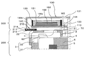
- FIG. FIG. 2 is a main part sectional view showing a rotating electric machine according to Embodiment 2 of the present invention.
- an opening edge of the cylindrical portion 130 b of the cover 130 is inserted into a groove 214 formed at a connection portion of the molding resin 211 of the insert molded body 210 with the opening edge of the cover 130.
- the other configuration is the same as that of the first embodiment.
- the opening edge of the cylindrical portion 130b of the cover 130 is inserted into the groove 214 formed in the molding resin 211 of the insert molded body 210 to form a labyrinth structure. Therefore, also in the second embodiment, it is possible to suppress foreign substances from flowing into cover 130.
- FIG. 3 is a fragmentary cross-sectional view showing a rotating electric machine according to Embodiment 3 of the present invention.
- a filler 215 such as a tape or an adhesive is filled in the groove 214 into which the opening edge of the cylindrical portion 130b of the cover 130 is inserted.
- the other configuration is the same as that of the second embodiment.
- the filler 215 is filled in the groove 214 into which the opening edge of the cylindrical portion 130b of the cover 130 is inserted. Therefore, according to the third embodiment, even a small foreign substance can be further prevented from flowing into cover 130.
- FIG. 4 is a fragmentary cross-sectional view showing a rotary electric machine according to Embodiment 4 of the present invention.
- an insert molded body 210 obtained by integrally molding a bus bar 212 and a molding resin 211 is in contact with the inner peripheral wall surface of the cylindrical portion 130 b of the cover 130.
- the other configuration is the same as that of the first embodiment.
- the insert molded body 210 is in contact with the inner peripheral wall surface of the cylindrical portion 130b of the cover 130, and closes the gap between the cover 130 and the rear bracket 2. Therefore, also in the fourth embodiment, it is possible to prevent foreign substances from flowing into cover 130.
- FIG. 5 is a fragmentary cross-sectional view showing a rotary electric machine according to Embodiment 5 of the present invention.
- an intake hole 132 is formed on the outer diameter side of the bottom 130a of the cover 130.
- a plurality of heat sink fins 145 having a small thickness in the circumferential direction extend radially outward from the outer diameter end of the heat sink 140 and are arranged in a plurality in the circumferential direction.
- the intake hole 132 faces the heat sink fin 145 in the axial direction.
- a plurality of bus bar radiating fins 213 having a small thickness in the circumferential direction extend from the bus bar 212 to the front side in the axial direction through the molding resin 21 and are arranged in a plurality in the circumferential direction.
- the bus bar radiating fins 213 are partially inserted into the exhaust ports 22. As a result, the bus bar radiation fins 213 are exposed to the flow of the cooling air exhausted from the exhaust port 22.
- the other configuration is the same as that of the first embodiment.
- the insert molded body 210 is in contact with the opening edge of the cylindrical portion 130b of the cover 130 to close the gap between the cover 130 and the rear bracket 2. Therefore, also in the fifth embodiment, the inflow of foreign matter into cover 130 is suppressed.
- the intake holes 131 and 132 are formed on the center side and the outer diameter side of the bottom portion 130a of the cover 130, the flow rates of the cooling air W2 and W3 are increased, and the heat-generating components can be effectively cooled.
- the intake hole 132 is formed on the outer diameter side of the bottom portion 130 a of the cover 130, and the heat sink fins 145 project radially outward from the outer diameter end of the heat sink 140. Therefore, the heat sink fins 145 are present in the ventilation path of the cooling air W3 sucked from the intake holes 132, and heat generated by the heat generating components is effectively radiated to the cooling air W3 via the heat sink fins 145. Further, since the insert molded body of the bus bar 212 exists in the ventilation path of the cooling air W3 sucked from the intake hole 132, heat generated in the bus bar 212 is effectively radiated.
- bus bar radiation fins 213 are exposed to the cooling air W2 and W3 discharged from the exhaust port 22, the heat generated in the bus bar 212 is effectively radiated. Since the bus bar radiating fins 213 can be formed integrally with the bus bar 212 when the bus bar 212 is formed, it is not necessary to add a step during insert molding in order to add the bus bar radiating fins 213.
- the heat sink fins 145 may be formed over the entire circumference of the heat sink 140 or may be formed partially in accordance with the location of the heating element to be cooled.
- the bus bar radiating fins 213 are made of the same material as the bus bar 212 and are formed integrally with the bus bar 212. However, the bus bar radiating fins may be made of the same material as the molding resin 211 and formed integrally with the molding resin 211. .
- FIG. 6 is a fragmentary cross-sectional view showing a rotary electric machine according to Embodiment 6 of the present invention.
- a flow path 146 through which a liquid refrigerant flows is formed in the heat sink 140.
- the other configuration is the same as that of the second embodiment.
- the opening edge of the cylindrical portion 130b of the cover 130 is inserted into the groove 214 formed in the insert molded body 210 to form a labyrinth structure. Therefore, also in the sixth embodiment, it is possible to suppress foreign substances from flowing into cover 130.
- the flow path 146 through which the liquid refrigerant flows is formed in the heat sink 140, even when the heat generation in the power supply unit 300 is large, the heat generation of the heat sink 140 can be effectively radiated. it can.
- the flow path 146 is formed in the heat sink 140 of the rotating electric machine according to the second embodiment.
- the flow path 146 may be formed in the heat sink 140 of the rotating electric machine according to another embodiment.
- the claw-pole type rotor using the field winding as the field means is used, but the embedded permanent magnet type rotor using the permanent magnet as the field means may be used.
- the insert molded body of the bus bar is used as the closing member, but the closing member is not limited to the insert molded body of the bus bar, and may close the gap between the cover and the rear bracket. Any member that can be used may be used.
- the rotating electric machine main body that operates as a motor is described, but the rotating electric machine main body may operate as a generator.
Landscapes
- Engineering & Computer Science (AREA)
- Power Engineering (AREA)
- Microelectronics & Electronic Packaging (AREA)
- Motor Or Generator Frames (AREA)
- Motor Or Generator Cooling System (AREA)
Abstract
本発明による回転電機は、回転電機本体と、上記回転電機本体と軸方向に1列に並んで配置されて、上記回転電機本体と一体化された電力変換装置と、を備え、上記電力変換装置は、反負荷側ブラケットの軸方向外側に上記反負荷側ブラケットと相対して配置されて上記反負荷側ブラケットに取り付けられ、底部および筒状部を有するカバーを備え、吸気口が、上記反負荷側ブラケットの回転子と軸方向に相対する領域に形成され、排気口が、上記反負荷側ブラケットのファンの径方向外方の領域に形成され、閉塞部材が、上記カバーと上記負荷側ブラケットとの間の隙間を塞いでいる。
Description
本発明は、例えば自動車などに搭載され、回転電機本体と電力変換装置とが一体化された回転電機に関するものである。
車両用回転電機は、回転電機本体と、制御装置と、を備えている。ここで、制御装置は、回転電機本体との間で電力、信号の授受を行う。省スペース性と搭載性の容易さ、さらに、回転電機本体と制御装置とを接続する配線ハーネスの縮小化の観点から、回転電機本体と制御装置とを一体化させた回転電機の開発が進められている。
特許文献1に記載の回転電機では、制御装置が回転電機本体の反負荷側に一体化されて構成されていた。そして、冷却風が、ロータの軸端に装着されたファンにより、径方向からヒートシンクに吸入され、ヒートシンクに形成されたフィンに沿って流れ、リヤハウジングの通風孔を通って回転電機本体内に流入し、ファンにより旋回されて、リヤハウジングの外部に排出される。
しかし、特許文献1においては、ロータの軸端に装着されたファンにより、冷却風を径方向外方から制御装置のパワー部のヒートシンクに吸入させていた。このため、ねじなどの異物が、径方向外方からヒートシンクとリヤハウジングとの間の隙間に入り、リヤハウジングの通風孔を通って回転電機本体内の回転部に到達するという問題があった。
この発明は、上記課題を解決するためになされたもので、回転電機本体内部への異物の侵入を抑制することができる回転電機を提供する。
この発明による回転電機は、回転電機本体と、上記回転電機本体と軸方向に1列に並んで配置されて、上記回転電機本体と一体化された電力変換装置と、を備え、上記回転電機本体は、負荷側ブラケットおよび反負荷側ブラケットを有するハウジングと、上記ハウジング内に回転可能に設けられた回転子と、上記回転子の軸方向の反負荷側の端部に固定されたファンと、上記ハウジングに保持されて、上記回転子と同軸に、かつ上記回転子の外径側に配置された固定子と、を備え、上記電力変換装置は、上記反負荷側ブラケットの軸方向外側に上記反負荷側ブラケットと相対して配置されて上記反負荷側ブラケットに取り付けられ、底部および筒状部を有するカバーを備え、吸気口が、上記反負荷側ブラケットの上記回転子と軸方向に相対する領域に形成され、排気口が、上記反負荷側ブラケットの上記ファンの径方向外方の領域に形成され、閉塞部材が、上記カバーと上記負荷側ブラケットとの間の隙間を塞いでいる。
本発明によれば、閉塞部材によりカバーと負荷側ブラケットとの間の隙間が塞がれているので、反負荷側ブラケットに形成された吸気口から回転電機本体の内部に異物が侵入することを抑制することができる。
実施の形態1.
図1は、この発明の実施の形態1に係る回転電機を示す片側断面図である。
図1は、この発明の実施の形態1に係る回転電機を示す片側断面図である。
図1において、回転電機は、回転電機本体200と、回転電機本体200と軸方向に並んで回転電機本体200の反負荷側に配設された電力変換装置としての電力供給ユニット300と、備える。回転電機は、回転電機本体200の軸方向を鉛直方向として、電力供給ユニット300を上方に位置させて、設置される。
回転電機本体200は、負荷側ブラケットであるフロントブラケット1および反負荷側ブラケットであるリヤブラケット2とからなるハウジングと、固定子鉄心31および固定子巻線32を有する固定子3と、シャフト4および界磁巻線5を有する回転子6と、を備えている。
フロントブラケット1は、鉄などの金属材料を用いて、底部と筒状部とからなる椀状に作製される。ベアリング71が、フロントブラケット1の底部の軸心位置に装着されている。吸気口11が、フロントブラケット1の底部に、ベアリング71を取り囲むように複数形成されている。排気口12が、フロントブラケット1の筒状部に、全周に渡って複数形成されている。
リヤブラケット2は、鉄などの金属材料を用いて、底部と筒状部とからなる椀状に作製される。ベアリング72が、リヤブラケット2の底部の軸心位置に装着されている。吸気口21が、リヤブラケット2の底部に、ベアリング72を取り囲むように複数形成されている。排気口22が、リヤブラケット2の筒状部に、全周に渡って複数形成されている。
固定子3は、円環状の固定子鉄心31と、固定子鉄心31に装着された固定子巻線32とを備える。固定子3は、固定子鉄心31を軸方向の両側からフロントブラケット1とリヤブラケット2との椀状の開口縁部に挟まれて、ハウジングに固定状態に保持されている。これにより、排気口12,22が、固定子巻線32のコイルエンドの径方向外方に配置される。
回転子6は、フロントブラケット1に設けられたベアリング71と、リヤブラケット2に設けられたベアリング72と、によりシャフト4が支持されて、ハウジング内に回転可能に収納されている。これにより、回転子6は、固定子3の内径側に、固定子3との間に微少な空隙を介して、同軸に配置されている。吸気口11,21は、回転子6と軸方向に相対するように配置される。
ファン81は、回転子6の軸方向の負荷側であるフロント側端面に固着されている。また、ファン82は、回転子6の軸方向の反負荷側であるリヤ側端面に固着されている。プーリー9が、フロントブラケット1からフロント側に突出するシャフト4の負荷側端部に装着されている。図示されていないが、プーリー9は、ベルトを介してエンジンの回転軸に連結されている。これにより、エンジンと回転電機本体200との間での回転エネルギーの授受が可能となっている。
電力供給ユニット300は、複数の半導体スイッチング素子により構成されたインバータ回路部150、インバータ回路部150の駆動を制御するCPUなどが実装された制御基板151、ブラシ100、回転センサ110、カバー130などを備える。そして、電力供給ユニット300は、バッテリなどの外部電源の直流電力を交流電力に変換して固定子巻線32に供給し、外部電源の直流電力を界磁巻線5に供給する。
インバータ回路部150は、半導体スイッチング素子がアルミ、銅などの金属基板、又はセラミック基板に、はんだなどで接合された状態で、ヒートシンク140の一面のケース126により囲まれた領域に固定される。これにより、インバータ回路部150とヒートシンク140との間の電気絶縁性が確保される。グリース、接着剤などの伝熱材を用いて、インバータ回路部150の半導体スイッチング素子が接合された基板とヒートシンク140とを固定した場合、伝熱材を薄くすることができる。また、はんだなどの導電材を用いて、インバータ回路部150の半導体スイッチング素子が接合された基板とヒートシンク140とを固定することができる。
一方、インバータ回路部150のリードフレームは、シート状の接着剤、ゲル状の接着剤などの伝熱材を介してヒートシンク140に固定される。これにより、固定部材および接合工程を省略できるとともに、固定部の熱抵抗を低減できる。ここで、リードフレームとヒートシンク140が同電位の場合には、はんだ、ばね、ねじなどの部材でリードフレームとヒートシンク140とを固定できるので、固定部の熱抵抗を低減できるだけでなく、高温での固定信頼性を向上できる。
制御基板151は、ヒートシンク140の一面のケース126で囲まれた領域に取り付けられる。そして、インバータ回路部150および制御基板151が、ケース126内に充填されたポッティング材152内に埋め込まれる。これにより、インバータ回路部150および制御基板151の防水性、防塵性、および耐振性が向上される。
インバータ回路部150および制御基板151が取り付けられたヒートシンク140は、回転電機本体200のリヤ側に、リヤブラケット2の底部と相対するように配置され、固定部材によりリヤブラケット2に固定される。
ブラシ100は、リヤブラケット2からリヤ側に突出するシャフト4の反負荷側端部に接触するように、リヤブラケット2のリヤ側に配置されている。回転センサ110は、リヤブラケット2からリヤ側に突出するシャフト4の反負荷側端部に配置されている。なお、回転センサ110は、ホール素子、レゾルバなどで構成される。
カバー130は、底部130aと筒状部130bとからなる椀状に形成されている。カバー130は、リヤ側から、インバータ回路部150および制御基板151が取り付けられたヒートシンク140、ブラシ100、回転センサ110などを覆うように配置され、リヤブラケット2に固定される。これにより、水、粉塵などから電子部品が保護される。ケース126およびカバー130は、樹脂を用いることで電気絶縁性および軽量性を得ることができ、金属を用いることで放熱性を得ることができる。
吸気穴144は、ヒートシンク140のケース126が取り付けられている位置より内径側に形成される。また、吸気穴131は、吸気穴144のリヤ側に位置するようにカバー130の底部130aに形成される。
電力供給ユニット300と固定子巻線32とは、バスバー212により電気的に接続される。バスバー212は、インサート成形されて、樹脂と一体化されている。インサート成形体201は、バスバー212と成形樹脂211とを一体化した複合部品である。これにより、バスバー212は、防水性が高められるとともに、リヤブラケット2、ヒートシンク140などの異電位の部材に対する電気絶縁性が確保される。バスバー212のインサート成形体210は、リヤブラケット2にねじなどにより取り付けられる。そして、インサート成形体210は、リヤブラケット2から径方向外方に突出し、カバー130の筒状部130bの開口縁部に接している。インサート成形体210は、リヤブラケット2の排気口22から排出される冷却風に曝される位置に配置されている。
つぎに、このように構成された回転電機における冷却動作について説明する。まず、回転子6が回転駆動されると、ファン81,82が連動して回転駆動される。これにより、図1の矢印で示すように、冷却風W1は、吸気口11からフロントブラケット1内に吸入され、ファン81により遠心方向に曲げられ、回転子6および固定子3を冷却した後、排気口12から排出される。一方、冷却風W2は、吸気穴131からカバー130内に吸入され、吸気穴144を通ってリヤブラケット2側に流入する。これにより、ブラシ100および回転センサ110が、冷却風W2によって冷却される。リヤブラケット2側に流入した冷却風W2は、ヒートシンク140のリヤブラケット2側の面に沿って流れ、吸気口21からリヤブラケット2内に流入する。そこで、冷却風W2は、ファン82により遠心方向に曲げられ、回転子6および固定子3を冷却して排気口22から排出される。
これにより、冷却風W2がブラシ100および回転センサ110に当たり、シャフト4との摩擦によるブラシ100の温度上昇が抑制され、ブラシ100の長寿命化が図られる。また、回転センサ110が冷却され、回転センサ110の温度上昇が抑制される。
ここで、カバー130の吸気穴131は、カバー130の底部130aの中央側に形成されているが、カバー130の底部130aの外径側に形成されてもよい。この場合、吸気穴131からカバー130内に流入して吸気穴144に至る冷却風W2の経路が長くなり、多くの部品を冷却することができる。また、吸気穴131は、カバー130の筒状部130bに形成されてもよい。この場合、吸気穴131からカバー130内に流入した冷却風W2は、ヒートシンク140のリヤブラケット2と相対する面に沿って流れ、吸気口21からリヤブラケット2内に流入する。これにより、ヒートシンク140に接続された部品が効果的に冷却される。
従来技術では、制御ユニットが回転電機本体から離れて配置されていたので、制御ユニットのカバーと回転電機本体のリヤハウジングとの間に隙間が形成されていた。そこで、ねじなどの異物が、当該隙間から制御ユニットのヒートシンクとリヤハウジングとの間を通り、リヤハウジングの通風孔を通って回転電機本体内の回転部に到達していた。これにより、ファンなどの部品が損傷するおそれがあった。
実施の形態1では、電力供給ユニット300と固定子巻線32とを電気的に接続するバスバー212と成形樹脂211とを一体成形してなるインサート成形体210により、カバー130の筒状部130bの開口縁部とリヤブラケット2との間の隙間を塞いでいる。これにより、ねじなどの異物が、カバー130内に入り込み、吸気口21からリヤブラケット2内に流入する事態の発生が抑制される。すなわち、インサート成形体210は、閉塞部材を構成している。
実施の形態1では、バスバー212と成形樹脂211とを一体成形してなるインサート成形体210を用いてカバー130の筒状部130bの開口縁部とリヤブラケット2との間の隙間を塞いているので、新たな閉塞部材を用意する必要がない。
さらに、実施の形態1では、排気口22に近接する、カバー130の筒状部130bの開口縁部とリヤブラケット2との間の隙間が塞がれている。吸気穴131が排気口22から遠く離れたカバー130の底部130aの中央側に形成されている。そこで、排気口22から排出された、暖まった冷却風W2がカバー130内に再流入し、回転電機本体200および電力供給ユニット300の冷却性を低下させるような事態の発生が抑制される。ここで、暖まった冷却風W2のカバー内への再流入を抑制する観点から、吸気穴131は、カバー130の底部130aに形成されることが好ましい。また、吸気穴131は、カバー130の底部130aの中央側に形成されることがより好ましい。
カバー130とリヤブラケット2との間の隙間がバスバー212と成形樹脂211とを一体成形してなるインサート成形体210により塞がれているので、ヒートシンク140に異物流入防止用の突起を設ける必要がない。そこで、ヒートシンク140のリヤブラケット側の面を平坦面として形成でき、ヒートシンク140とリヤブラケット2との間の隙間を小さくすることができる。これにより、回転電機の軸長が短くなり、回転電機の軽量化、および車両への搭載性の向上が図られる。また、ヒートシンク140の軽量化が可能となり、低コスト化が図られる。さらに、バスバー212の長さが短くなるので、バスバー212の抵抗が小さくなり、発熱量が低減される、これにより、熱損失を抑制することができる。さらにまた、ヒートシンク140の面が平坦面となることで、ヒートシンク140での圧損が少なくなる。これにより、冷却風W2の風量が増加し、発熱部品の温度上昇が抑制される。
ここで、カバー130を金属製とすることで、電力供給ユニット300に入るノイズを反射あるいは吸収することができる。これにより、外部ノイズによる回転電機への影響を軽減できる。また、カバー130が電力供給ユニット300から出るノイズを反射あるいは吸収し、吸収周辺機器への影響を軽減できる。さらに、金属製であるバスバー212がカバー130とリヤブラケット2との間の隙間を塞いでいるので、ノイズの影響をより軽減できる効果が得られる。バスバー212と成形樹脂211とを一体成形してなるインサート成形体210がカバー130に接しているので、バスバー212での発熱がカバー130を介して効果的に放熱される。
回転電機本体200において、固定子巻線32が複数相の巻線で構成されている場合、バスバー212も巻線の相数に応じて複数となる。このとき、電気角位相の異なるバスバー212同士を同じインサート成形体210に一体成形することが好ましい。つまり、電気角位相の異なるバスバー212同士を同じインサート成形体210に一体成形することにより、一体成形された各バスバー212での発熱のピークのタイミングが分散される。これにより、バスバー212のインサート成形体210での温度上昇が抑制される。特に、電気角位相差が90°の時に最も発熱のピークのタイミングが分散されて均一化できる。このため、電気角位相差が90°のバスバー212同士を1つのインサート成形体210に一体成形することが好ましい。
なお、実施の形態1では、バスバー212と成形樹脂211とを一体成形してなるインサート成形体210がリヤブラケット2に取り付けられているが、インサート成形体210は、ヒートシンク140に取り付けられてもよい。
また、インサート成形体210は、カバー130より径方向外方に突出させることにより、異物のカバー130内への流入を、より抑制することができる。
また、インサート成形体210によりカバー130の筒状部130bとリヤブラケット2との間の隙間を閉塞する場合は、異物が流入する箇所のみを閉塞してもよいが、全周に渡って閉塞することが好ましい。
また、インサート成形体210によりカバー130の筒状部130bとリヤブラケット2との間の隙間を閉塞する場合は、異物が流入する箇所のみを閉塞してもよいが、全周に渡って閉塞することが好ましい。
実施の形態2.
図2は、この発明の実施の形態2に係る回転電機を示す要部断面図である。
図2は、この発明の実施の形態2に係る回転電機を示す要部断面図である。
図2において、カバー130の筒状部130bの開口縁部は、インサート成形体210の成形樹脂211の、カバー130の開口縁部との接続部に形成された溝214に挿入されている。
なお、他の構成は、上記実施の形態1と同様に構成されている。
なお、他の構成は、上記実施の形態1と同様に構成されている。
この実施の形態2では、カバー130の筒状部130bの開口縁部が、インサート成形体210の成形樹脂211に形成された溝214に挿入されて、ラビリンス構造となっている。したがって、実施の形態2においても、異物のカバー130内への流入を抑制することができる。
実施の形態3.
図3は、この発明の実施の形態3に係る回転電機を示す要部断面図である。
図3は、この発明の実施の形態3に係る回転電機を示す要部断面図である。
図3において、カバー130の筒状部130bの開口縁部が挿入された溝214内に、テープ、接着剤などの充填剤215が充填されている。
なお、他の構成は、上記実施の形態2と同様に構成されている。
なお、他の構成は、上記実施の形態2と同様に構成されている。
この実施の形態3では、カバー130の筒状部130bの開口縁部が挿入された溝214内に充填剤215が充填されている。したがって、実施の形態3によれば、小さな異物でも、カバー130内への流入をより抑制することができる。
実施の形態4.
図4は、この発明の実施の形態4に係る回転電機を示す要部断面図である。
図4は、この発明の実施の形態4に係る回転電機を示す要部断面図である。
図4において、バスバー212と成形樹脂211とを一体成形してなるインサート成形体210が、カバー130の筒状部130bの内周壁面に接している。
なお、他の構成は、上記実施の形態1と同様に構成されている。
なお、他の構成は、上記実施の形態1と同様に構成されている。
この実施の形態4では、インサート成形体210が、カバー130の筒状部130bの内周壁面に接して、カバー130とリヤブラケット2との間の隙間を塞いでいる。したがって、実施の形態4においても、異物のカバー130内への流入を抑制することができる。
この場合、電力供給ユニット300が機能追加により大型化した場合においても、インサート成形体210をカバー130より径方向外方に突出させる必要がなく、カバー130とリヤブラケット2との隙間を効果的に閉塞できる。
実施の形態5.
図5は、この発明の実施の形態5に係る回転電機を示す要部断面図である。
図5は、この発明の実施の形態5に係る回転電機を示す要部断面図である。
図5において、吸気穴132が、カバー130の底部130aの外径側に形成されている。周方向厚みの薄いヒートシンク放熱フィン145は、ヒートシンク140の外径側端部から径方向外方向に延びて、周方向に複数配置されている。吸気穴132は、ヒートシンク放熱フィン145と軸方向に相対している。周方向厚みの薄いバスバー放熱フィン213は、バスバー212から成形樹脂21を貫通して軸方向フロント側に延びて、周方向に複数配置されている。バスバー放熱フィン213は、その一部が、排気口22内に挿入されている。これにより、バスバー放熱フィン213は、排気口22から排気される冷却風の流れに曝される。
なお、他の構成は、上記実施の形態1と同様に構成されている。
なお、他の構成は、上記実施の形態1と同様に構成されている。
この実施の形態5では、インサート成形体210がカバー130の筒状部130bの開口縁部に接して、カバー130とリヤブラケット2との間の隙間を塞いでいる。したがって、実施の形態5においても、カバー130内への異物の流入が抑制される。
吸気穴131および132が、カバー130の底部130aの中央側と外径側とに形成されているので、冷却風W2およびW3の風量が増大し、発熱部品を効果的に冷却することができる。
吸気穴132は、カバー130の底部130aの外径側に形成され、ヒートシンク放熱フィン145は、ヒートシンク140の外径側端部から径方向外方に突出している。そこで、ヒートシンク放熱フィン145は、吸気穴132から吸入された冷却風W3の通風路に存在し、発熱部品での発熱がヒートシンク放熱フィン145を介して効果的に冷却風W3に放熱される。また、バスバー212のインサート成形体が吸気穴132から吸入された冷却風W3の通風路に存在するので、バスバー212での発熱が効果的に放熱される。
吸気穴132は、カバー130の底部130aの外径側に形成され、ヒートシンク放熱フィン145は、ヒートシンク140の外径側端部から径方向外方に突出している。そこで、ヒートシンク放熱フィン145は、吸気穴132から吸入された冷却風W3の通風路に存在し、発熱部品での発熱がヒートシンク放熱フィン145を介して効果的に冷却風W3に放熱される。また、バスバー212のインサート成形体が吸気穴132から吸入された冷却風W3の通風路に存在するので、バスバー212での発熱が効果的に放熱される。
バスバー放熱フィン213は、排気口22から排出される冷却風W2およびW3に曝されるので、バスバー212での発熱が効果的に放熱される。
バスバー放熱フィン213は、バスバー212の形成時にバスバー212と一体に形成できるので、バスバー放熱フィン213を付加するために、インサート成形時に工程を追加する必要が無い。
バスバー放熱フィン213は、バスバー212の形成時にバスバー212と一体に形成できるので、バスバー放熱フィン213を付加するために、インサート成形時に工程を追加する必要が無い。
なお、ヒートシンク放熱フィン145は、ヒートシンク140の全周に渡って形成してもよく、冷却すべき発熱体の場所に合わせて部分的に形成してもよい。
また、バスバー放熱フィン213は、バスバー212と同一材料で、バスバー212と一体に形成されているが、バスバー放熱フィンは、成形樹脂211と同一材料で、成形樹脂211と一体に形成されてもよい。
また、バスバー放熱フィン213は、バスバー212と同一材料で、バスバー212と一体に形成されているが、バスバー放熱フィンは、成形樹脂211と同一材料で、成形樹脂211と一体に形成されてもよい。
実施の形態6.
図6は、この発明の実施の形態6に係る回転電機を示す要部断面図である。
図6は、この発明の実施の形態6に係る回転電機を示す要部断面図である。
図6において、液冷媒を流通させる流路146がヒートシンク140に形成されている。
なお、他の構成は、上記実施の形態2と同様に構成されている。
なお、他の構成は、上記実施の形態2と同様に構成されている。
実施の形態6では、カバー130の筒状部130bの開口縁部が、インサート成形体210に形成された溝214に挿入されて、ラビリンス構造となっている。したがって、実施の形態6においても、異物のカバー130内への流入を抑制することができる。
実施の形態6では、液冷媒を流通させる流路146がヒートシンク140の中に形成されているので、電力供給ユニット300での発熱が大きい場合でも、ヒートシンク140の発熱を効果的に放熱することができる。
実施の形態6では、液冷媒を流通させる流路146がヒートシンク140の中に形成されているので、電力供給ユニット300での発熱が大きい場合でも、ヒートシンク140の発熱を効果的に放熱することができる。
実施の形態6では、実施の形態2の回転電機のヒートシンク140に流路146を形成しているが、他の実施の形態の回転電機のヒートシンク140に流路146を形成してもよい。
なお、上記各実施の形態では、界磁巻線を界磁手段とするクローポール型の回転子を用いているが、永久磁石を界磁手段とする永久磁石埋込型回転子を用いてもよい。
また、上記各実施の形態では、バスバーのインサート成形体を閉塞部材として用いているが、閉塞部材は、バスバーのインサート成形体に限定されず、カバーとリヤブラケットとの間の隙間を塞ぐことができる部材であればよい。
また、上記各実施の形態では、電動機として動作する回転電機本体について説明しているが、回転電機本体は、発電機として動作するものでもよい。
また、上記各実施の形態では、バスバーのインサート成形体を閉塞部材として用いているが、閉塞部材は、バスバーのインサート成形体に限定されず、カバーとリヤブラケットとの間の隙間を塞ぐことができる部材であればよい。
また、上記各実施の形態では、電動機として動作する回転電機本体について説明しているが、回転電機本体は、発電機として動作するものでもよい。
なお、本発明の実施の形態を詳述したが、本発明は上記実施の形態に限定されるものではなく、種々の設計変更を行うことが可能である。
1 フロントブラケット(負荷側ブラケット)、2 リヤブラケット(反負荷側ブラケット)、3 固定子、6 回転子、21 吸気口、22 排気口、82 ファン、130 カバー、130a 底部、130b 筒状部、140 ヒートシンク、145 ヒートシンク放熱フィン、146 流路、150 インバータ回路部、200 回転電機本体、210 インサート成形体、211 成形樹脂、212 バスバー、213 バスバー放熱フィン、214 溝、300 電力供給ユニット(電力変換装置)。
Claims (16)
- 回転電機本体と、上記回転電機本体と軸方向に1列に並んで配置されて、上記回転電機本体と一体化された電力変換装置と、を備え、
上記回転電機本体は、負荷側ブラケットおよび反負荷側ブラケットを有するハウジングと、上記ハウジング内に回転可能に設けられた回転子と、上記回転子の軸方向の反負荷側の端部に固定されたファンと、上記ハウジングに保持されて、上記回転子と同軸に、かつ上記回転子の外径側に配置された固定子と、を備え、
上記電力変換装置は、上記反負荷側ブラケットの軸方向外側に上記反負荷側ブラケットと相対して配置されて上記反負荷側ブラケットに取り付けられ、底部および筒状部を有するカバーを備え、
吸気口が、上記反負荷側ブラケットの上記回転子と軸方向に相対する領域に形成され、
排気口が、上記反負荷側ブラケットの上記ファンの径方向外方の領域に形成され、
閉塞部材が、上記カバーと上記負荷側ブラケットとの間の隙間を塞いでいる回転電機。 - 上記閉塞部材は、上記カバーの上記筒状部に接する状態で、上記反負荷側ブラケットに固定されている請求項1記載の回転電機。
- 上記閉塞部材は、上記カバーの上記筒状部の上記反負荷側ブラケット側の端面に接している請求項2記載の回転電機。
- 上記カバーの上記筒状部の開口縁部が、上記閉塞部材に形成された溝内に挿入されている請求項3記載の回転電機。
- 上記閉塞部材は、上記カバーの上記筒状部の内周壁面に接している請求項2記載の回転電機。
- 上記カバーと上記閉塞部材とが接着されている請求項1から請求項5のいずれか1項に記載の回転電機。
- 上記カバーの上記筒状部の開口縁部は、上記反負荷側ブラケットより径方向外側に配置されている請求項1から請求項6のいずれか1項に記載の回転電機。
- 上記閉塞部材は、上記電力変換装置と上記固定子の固定子巻線とを電気的に接続するバスバーのインサート成形体である請求項1から請求項7のいずれか1項に記載の回転電機。
- 上記バスバーは、位相の異なる電流が通電される複数のバスバーである請求項8記載の回転電機。
- 上記複数のバスバーに通電される電流の位相差は90°である請求項9記載の回転電機。
- 上記インサート成形体は、上記排気口から排出される冷却風に曝されるように配置されている請求項8から請求項10のいずれか1項に記載の回転電機。
- 上記インサート成形体は、上記バスバー又は上記インサート成形体の成形樹脂から突出するバスバー放熱フィンを有し、上記バスバー放熱フィンが、上記排気口から排出される冷却風に曝されるように配置されている請求項11記載の回転電機。
- 上記電力変換装置は、上記反負荷側ブラケットの軸方向外側に上記反負荷側ブラケットと相対して配置されたヒートシンクを備え、上記ヒートシンクの上記反負荷側ブラケットと相対する面が平坦面である請求項1から請求項12のいずれか1項に記載の回転電機。
- 上記ヒートシンクは、上記ヒートシンクから径方向外方に突出するヒートシンク放熱フィンを有し、
吸気穴が、上記カバーの上記底部130aの上記ヒートシンク放熱フィンと相対する領域に形成されている請求項13記載の回転電機。 - 液冷媒の流路が上記ヒートシンクに形成されている請求項13又は請求項14記載の回転電機。
- 上記カバーは、金属製である請求項1から請求項15のいずれか1項に記載の回転電機。
Priority Applications (4)
| Application Number | Priority Date | Filing Date | Title |
|---|---|---|---|
| EP18926789.1A EP3826148B1 (en) | 2018-07-17 | 2018-07-17 | Rotating electric machine |
| JP2020530749A JP6918242B2 (ja) | 2018-07-17 | 2018-07-17 | 回転電機 |
| PCT/JP2018/026631 WO2020016911A1 (ja) | 2018-07-17 | 2018-07-17 | 回転電機 |
| CN201880095561.0A CN112385123B (zh) | 2018-07-17 | 2018-07-17 | 旋转电机 |
Applications Claiming Priority (1)
| Application Number | Priority Date | Filing Date | Title |
|---|---|---|---|
| PCT/JP2018/026631 WO2020016911A1 (ja) | 2018-07-17 | 2018-07-17 | 回転電機 |
Publications (1)
| Publication Number | Publication Date |
|---|---|
| WO2020016911A1 true WO2020016911A1 (ja) | 2020-01-23 |
Family
ID=69165037
Family Applications (1)
| Application Number | Title | Priority Date | Filing Date |
|---|---|---|---|
| PCT/JP2018/026631 Ceased WO2020016911A1 (ja) | 2018-07-17 | 2018-07-17 | 回転電機 |
Country Status (4)
| Country | Link |
|---|---|
| EP (1) | EP3826148B1 (ja) |
| JP (1) | JP6918242B2 (ja) |
| CN (1) | CN112385123B (ja) |
| WO (1) | WO2020016911A1 (ja) |
Cited By (2)
| Publication number | Priority date | Publication date | Assignee | Title |
|---|---|---|---|---|
| JP2022070400A (ja) * | 2020-10-27 | 2022-05-13 | 三菱電機株式会社 | 回転電機 |
| JPWO2022239484A1 (ja) * | 2021-05-14 | 2022-11-17 |
Citations (4)
| Publication number | Priority date | Publication date | Assignee | Title |
|---|---|---|---|---|
| JP4229947B2 (ja) | 2006-01-16 | 2009-02-25 | 三菱電機株式会社 | 制御装置一体型回転電機およびその製造方法 |
| JP2014143833A (ja) * | 2013-01-24 | 2014-08-07 | Mitsubishi Electric Corp | 回転電機 |
| JP2016042770A (ja) * | 2014-08-19 | 2016-03-31 | 三菱電機株式会社 | 電力供給ユニット一体型回転電機 |
| JP2017221083A (ja) * | 2016-06-10 | 2017-12-14 | 株式会社豊田自動織機 | インバータ一体形回転電機 |
Family Cites Families (8)
| Publication number | Priority date | Publication date | Assignee | Title |
|---|---|---|---|---|
| JP4123436B2 (ja) * | 2003-02-18 | 2008-07-23 | 株式会社デンソー | インバータ一体型交流モータ |
| JP4156542B2 (ja) * | 2004-03-03 | 2008-09-24 | 三菱電機株式会社 | 車両用回転電機装置 |
| JP5368532B2 (ja) * | 2011-11-08 | 2013-12-18 | 三菱電機株式会社 | 電力供給ユニット一体型回転電機 |
| DE102011087602B4 (de) * | 2011-12-01 | 2021-06-02 | Seg Automotive Germany Gmbh | Elektrische Maschine |
| US9467030B2 (en) * | 2013-03-15 | 2016-10-11 | Regal Beloit Australia Pty Ltd | Air-cooled electric machine and method of assembling the same |
| US20150042213A1 (en) * | 2013-08-07 | 2015-02-12 | Remy Technologies, Llc | Electric machine having venturi effect cooling enhancement |
| JP5661167B1 (ja) * | 2013-11-08 | 2015-01-28 | 三菱電機株式会社 | 電力供給ユニット一体型回転電機 |
| JP6129286B1 (ja) * | 2015-12-02 | 2017-05-17 | 三菱電機株式会社 | 電力供給ユニット一体型回転電機 |
-
2018
- 2018-07-17 CN CN201880095561.0A patent/CN112385123B/zh active Active
- 2018-07-17 EP EP18926789.1A patent/EP3826148B1/en active Active
- 2018-07-17 WO PCT/JP2018/026631 patent/WO2020016911A1/ja not_active Ceased
- 2018-07-17 JP JP2020530749A patent/JP6918242B2/ja active Active
Patent Citations (4)
| Publication number | Priority date | Publication date | Assignee | Title |
|---|---|---|---|---|
| JP4229947B2 (ja) | 2006-01-16 | 2009-02-25 | 三菱電機株式会社 | 制御装置一体型回転電機およびその製造方法 |
| JP2014143833A (ja) * | 2013-01-24 | 2014-08-07 | Mitsubishi Electric Corp | 回転電機 |
| JP2016042770A (ja) * | 2014-08-19 | 2016-03-31 | 三菱電機株式会社 | 電力供給ユニット一体型回転電機 |
| JP2017221083A (ja) * | 2016-06-10 | 2017-12-14 | 株式会社豊田自動織機 | インバータ一体形回転電機 |
Non-Patent Citations (1)
| Title |
|---|
| See also references of EP3826148A4 |
Cited By (3)
| Publication number | Priority date | Publication date | Assignee | Title |
|---|---|---|---|---|
| JP2022070400A (ja) * | 2020-10-27 | 2022-05-13 | 三菱電機株式会社 | 回転電機 |
| JPWO2022239484A1 (ja) * | 2021-05-14 | 2022-11-17 | ||
| WO2022239484A1 (ja) * | 2021-05-14 | 2022-11-17 | 株式会社アイシン | ポンプ装置 |
Also Published As
| Publication number | Publication date |
|---|---|
| EP3826148A4 (en) | 2021-07-14 |
| CN112385123B (zh) | 2024-06-28 |
| JP6918242B2 (ja) | 2021-08-11 |
| EP3826148A1 (en) | 2021-05-26 |
| CN112385123A (zh) | 2021-02-19 |
| EP3826148B1 (en) | 2023-05-10 |
| JPWO2020016911A1 (ja) | 2020-12-17 |
Similar Documents
| Publication | Publication Date | Title |
|---|---|---|
| JP6621491B2 (ja) | 回転電機 | |
| JP5542977B1 (ja) | 回転電機 | |
| CN108141107B (zh) | 电动机 | |
| CN113141088B (zh) | 旋转电机 | |
| CN104505987B (zh) | 旋转电机 | |
| JP5893099B1 (ja) | 電力供給ユニット一体型回転電機 | |
| JP6312093B2 (ja) | 回転電機 | |
| JP4340305B2 (ja) | 車両用交流発電機 | |
| CN107852071A (zh) | 旋转电机 | |
| CN111869057B (zh) | 带电刷的旋转电机 | |
| JP2015092800A (ja) | 電力供給ユニット一体型回転電機 | |
| JP2004312852A (ja) | 車両用回転電機 | |
| JP6918242B2 (ja) | 回転電機 | |
| JP6207650B2 (ja) | 回転電機 | |
| JP5270718B2 (ja) | 電力供給ユニット一体型回転電機 | |
| JP3774863B2 (ja) | 回転電機 | |
| JP5430211B2 (ja) | 駆動モータ | |
| JP4879772B2 (ja) | 電気機器 | |
| CN112994362B (zh) | 旋转电机 | |
| JP2003274606A (ja) | 回転電機 | |
| JP7086238B1 (ja) | 制御装置一体型回転電機 | |
| JP6890651B1 (ja) | 回転電機 | |
| JP2006352946A (ja) | 車両用回転電機 | |
| CN110024270A (zh) | 具有液体冷却功能的电机 | |
| JP2004312960A (ja) | インバータ一体型電動機 |
Legal Events
| Date | Code | Title | Description |
|---|---|---|---|
| 121 | Ep: the epo has been informed by wipo that ep was designated in this application |
Ref document number: 18926789 Country of ref document: EP Kind code of ref document: A1 |
|
| ENP | Entry into the national phase |
Ref document number: 2020530749 Country of ref document: JP Kind code of ref document: A |
|
| NENP | Non-entry into the national phase |
Ref country code: DE |
|
| ENP | Entry into the national phase |
Ref document number: 2018926789 Country of ref document: EP Effective date: 20210217 |