WO2020017003A1 - 摺動部材 - Google Patents
摺動部材 Download PDFInfo
- Publication number
- WO2020017003A1 WO2020017003A1 PCT/JP2018/027156 JP2018027156W WO2020017003A1 WO 2020017003 A1 WO2020017003 A1 WO 2020017003A1 JP 2018027156 W JP2018027156 W JP 2018027156W WO 2020017003 A1 WO2020017003 A1 WO 2020017003A1
- Authority
- WO
- WIPO (PCT)
- Prior art keywords
- metal material
- particles
- corrosion
- material particles
- sliding member
- Prior art date
- Legal status (The legal status is an assumption and is not a legal conclusion. Google has not performed a legal analysis and makes no representation as to the accuracy of the status listed.)
- Ceased
Links
Images


Classifications
-
- C—CHEMISTRY; METALLURGY
- C23—COATING METALLIC MATERIAL; COATING MATERIAL WITH METALLIC MATERIAL; CHEMICAL SURFACE TREATMENT; DIFFUSION TREATMENT OF METALLIC MATERIAL; COATING BY VACUUM EVAPORATION, BY SPUTTERING, BY ION IMPLANTATION OR BY CHEMICAL VAPOUR DEPOSITION, IN GENERAL; INHIBITING CORROSION OF METALLIC MATERIAL OR INCRUSTATION IN GENERAL
- C23C—COATING METALLIC MATERIAL; COATING MATERIAL WITH METALLIC MATERIAL; SURFACE TREATMENT OF METALLIC MATERIAL BY DIFFUSION INTO THE SURFACE, BY CHEMICAL CONVERSION OR SUBSTITUTION; COATING BY VACUUM EVAPORATION, BY SPUTTERING, BY ION IMPLANTATION OR BY CHEMICAL VAPOUR DEPOSITION, IN GENERAL
- C23C24/00—Coating starting from inorganic powder
- C23C24/08—Coating starting from inorganic powder by application of heat or pressure and heat
- C23C24/082—Coating starting from inorganic powder by application of heat or pressure and heat without intermediate formation of a liquid in the layer
- C23C24/085—Coating with metallic material, i.e. metals or metal alloys, optionally comprising hard particles, e.g. oxides, carbides or nitrides
-
- F—MECHANICAL ENGINEERING; LIGHTING; HEATING; WEAPONS; BLASTING
- F01—MACHINES OR ENGINES IN GENERAL; ENGINE PLANTS IN GENERAL; STEAM ENGINES
- F01L—CYCLICALLY OPERATING VALVES FOR MACHINES OR ENGINES
- F01L3/00—Lift-valve, i.e. cut-off apparatus with closure members having at least a component of their opening and closing motion perpendicular to the closing faces; Parts or accessories thereof
- F01L3/02—Selecting particular materials for valve-members or valve-seats; Valve-members or valve-seats composed of two or more materials
- F01L3/04—Coated valve members or valve-seats
-
- B—PERFORMING OPERATIONS; TRANSPORTING
- B22—CASTING; POWDER METALLURGY
- B22F—WORKING METALLIC POWDER; MANUFACTURE OF ARTICLES FROM METALLIC POWDER; MAKING METALLIC POWDER; APPARATUS OR DEVICES SPECIALLY ADAPTED FOR METALLIC POWDER
- B22F7/00—Manufacture of composite layers, workpieces, or articles, comprising metallic powder, by sintering the powder, with or without compacting wherein at least one part is obtained by sintering or compression
- B22F7/06—Manufacture of composite layers, workpieces, or articles, comprising metallic powder, by sintering the powder, with or without compacting wherein at least one part is obtained by sintering or compression of composite workpieces or articles from parts, e.g. to form tipped tools
- B22F7/08—Manufacture of composite layers, workpieces, or articles, comprising metallic powder, by sintering the powder, with or without compacting wherein at least one part is obtained by sintering or compression of composite workpieces or articles from parts, e.g. to form tipped tools with one or more parts not made from powder
-
- C—CHEMISTRY; METALLURGY
- C23—COATING METALLIC MATERIAL; COATING MATERIAL WITH METALLIC MATERIAL; CHEMICAL SURFACE TREATMENT; DIFFUSION TREATMENT OF METALLIC MATERIAL; COATING BY VACUUM EVAPORATION, BY SPUTTERING, BY ION IMPLANTATION OR BY CHEMICAL VAPOUR DEPOSITION, IN GENERAL; INHIBITING CORROSION OF METALLIC MATERIAL OR INCRUSTATION IN GENERAL
- C23C—COATING METALLIC MATERIAL; COATING MATERIAL WITH METALLIC MATERIAL; SURFACE TREATMENT OF METALLIC MATERIAL BY DIFFUSION INTO THE SURFACE, BY CHEMICAL CONVERSION OR SUBSTITUTION; COATING BY VACUUM EVAPORATION, BY SPUTTERING, BY ION IMPLANTATION OR BY CHEMICAL VAPOUR DEPOSITION, IN GENERAL
- C23C24/00—Coating starting from inorganic powder
- C23C24/08—Coating starting from inorganic powder by application of heat or pressure and heat
- C23C24/082—Coating starting from inorganic powder by application of heat or pressure and heat without intermediate formation of a liquid in the layer
- C23C24/085—Coating with metallic material, i.e. metals or metal alloys, optionally comprising hard particles, e.g. oxides, carbides or nitrides
- C23C24/087—Coating with metal alloys or metal elements only
-
- C—CHEMISTRY; METALLURGY
- C23—COATING METALLIC MATERIAL; COATING MATERIAL WITH METALLIC MATERIAL; CHEMICAL SURFACE TREATMENT; DIFFUSION TREATMENT OF METALLIC MATERIAL; COATING BY VACUUM EVAPORATION, BY SPUTTERING, BY ION IMPLANTATION OR BY CHEMICAL VAPOUR DEPOSITION, IN GENERAL; INHIBITING CORROSION OF METALLIC MATERIAL OR INCRUSTATION IN GENERAL
- C23C—COATING METALLIC MATERIAL; COATING MATERIAL WITH METALLIC MATERIAL; SURFACE TREATMENT OF METALLIC MATERIAL BY DIFFUSION INTO THE SURFACE, BY CHEMICAL CONVERSION OR SUBSTITUTION; COATING BY VACUUM EVAPORATION, BY SPUTTERING, BY ION IMPLANTATION OR BY CHEMICAL VAPOUR DEPOSITION, IN GENERAL
- C23C30/00—Coating with metallic material characterised only by the composition of the metallic material, i.e. not characterised by the coating process
-
- F—MECHANICAL ENGINEERING; LIGHTING; HEATING; WEAPONS; BLASTING
- F01—MACHINES OR ENGINES IN GENERAL; ENGINE PLANTS IN GENERAL; STEAM ENGINES
- F01L—CYCLICALLY OPERATING VALVES FOR MACHINES OR ENGINES
- F01L3/00—Lift-valve, i.e. cut-off apparatus with closure members having at least a component of their opening and closing motion perpendicular to the closing faces; Parts or accessories thereof
- F01L3/02—Selecting particular materials for valve-members or valve-seats; Valve-members or valve-seats composed of two or more materials
-
- F—MECHANICAL ENGINEERING; LIGHTING; HEATING; WEAPONS; BLASTING
- F16—ENGINEERING ELEMENTS AND UNITS; GENERAL MEASURES FOR PRODUCING AND MAINTAINING EFFECTIVE FUNCTIONING OF MACHINES OR INSTALLATIONS; THERMAL INSULATION IN GENERAL
- F16C—SHAFTS; FLEXIBLE SHAFTS; ELEMENTS OR CRANKSHAFT MECHANISMS; ROTARY BODIES OTHER THAN GEARING ELEMENTS; BEARINGS
- F16C33/00—Parts of bearings; Special methods for making bearings or parts thereof
- F16C33/02—Parts of sliding-contact bearings
- F16C33/04—Brasses; Bushes; Linings
- F16C33/06—Sliding surface mainly made of metal
- F16C33/12—Structural composition; Use of special materials or surface treatments, e.g. for rust-proofing
- F16C33/121—Use of special materials
-
- F—MECHANICAL ENGINEERING; LIGHTING; HEATING; WEAPONS; BLASTING
- F16—ENGINEERING ELEMENTS AND UNITS; GENERAL MEASURES FOR PRODUCING AND MAINTAINING EFFECTIVE FUNCTIONING OF MACHINES OR INSTALLATIONS; THERMAL INSULATION IN GENERAL
- F16C—SHAFTS; FLEXIBLE SHAFTS; ELEMENTS OR CRANKSHAFT MECHANISMS; ROTARY BODIES OTHER THAN GEARING ELEMENTS; BEARINGS
- F16C33/00—Parts of bearings; Special methods for making bearings or parts thereof
- F16C33/02—Parts of sliding-contact bearings
- F16C33/04—Brasses; Bushes; Linings
- F16C33/06—Sliding surface mainly made of metal
- F16C33/12—Structural composition; Use of special materials or surface treatments, e.g. for rust-proofing
- F16C33/128—Porous bearings, e.g. bushes of sintered alloy
-
- B—PERFORMING OPERATIONS; TRANSPORTING
- B22—CASTING; POWDER METALLURGY
- B22F—WORKING METALLIC POWDER; MANUFACTURE OF ARTICLES FROM METALLIC POWDER; MAKING METALLIC POWDER; APPARATUS OR DEVICES SPECIALLY ADAPTED FOR METALLIC POWDER
- B22F7/00—Manufacture of composite layers, workpieces, or articles, comprising metallic powder, by sintering the powder, with or without compacting wherein at least one part is obtained by sintering or compression
- B22F7/02—Manufacture of composite layers, workpieces, or articles, comprising metallic powder, by sintering the powder, with or without compacting wherein at least one part is obtained by sintering or compression of composite layers
- B22F7/04—Manufacture of composite layers, workpieces, or articles, comprising metallic powder, by sintering the powder, with or without compacting wherein at least one part is obtained by sintering or compression of composite layers with one or more layers not made from powder, e.g. made from solid metal
- B22F2007/042—Manufacture of composite layers, workpieces, or articles, comprising metallic powder, by sintering the powder, with or without compacting wherein at least one part is obtained by sintering or compression of composite layers with one or more layers not made from powder, e.g. made from solid metal characterised by the layer forming method
-
- B—PERFORMING OPERATIONS; TRANSPORTING
- B22—CASTING; POWDER METALLURGY
- B22F—WORKING METALLIC POWDER; MANUFACTURE OF ARTICLES FROM METALLIC POWDER; MAKING METALLIC POWDER; APPARATUS OR DEVICES SPECIALLY ADAPTED FOR METALLIC POWDER
- B22F2998/00—Supplementary information concerning processes or compositions relating to powder metallurgy
- B22F2998/10—Processes characterised by the sequence of their steps
-
- C—CHEMISTRY; METALLURGY
- C22—METALLURGY; FERROUS OR NON-FERROUS ALLOYS; TREATMENT OF ALLOYS OR NON-FERROUS METALS
- C22C—ALLOYS
- C22C33/00—Making ferrous alloys
- C22C33/02—Making ferrous alloys by powder metallurgy
-
- C—CHEMISTRY; METALLURGY
- C23—COATING METALLIC MATERIAL; COATING MATERIAL WITH METALLIC MATERIAL; CHEMICAL SURFACE TREATMENT; DIFFUSION TREATMENT OF METALLIC MATERIAL; COATING BY VACUUM EVAPORATION, BY SPUTTERING, BY ION IMPLANTATION OR BY CHEMICAL VAPOUR DEPOSITION, IN GENERAL; INHIBITING CORROSION OF METALLIC MATERIAL OR INCRUSTATION IN GENERAL
- C23C—COATING METALLIC MATERIAL; COATING MATERIAL WITH METALLIC MATERIAL; SURFACE TREATMENT OF METALLIC MATERIAL BY DIFFUSION INTO THE SURFACE, BY CHEMICAL CONVERSION OR SUBSTITUTION; COATING BY VACUUM EVAPORATION, BY SPUTTERING, BY ION IMPLANTATION OR BY CHEMICAL VAPOUR DEPOSITION, IN GENERAL
- C23C24/00—Coating starting from inorganic powder
- C23C24/02—Coating starting from inorganic powder by application of pressure only
- C23C24/04—Impact or kinetic deposition of particles
-
- F—MECHANICAL ENGINEERING; LIGHTING; HEATING; WEAPONS; BLASTING
- F01—MACHINES OR ENGINES IN GENERAL; ENGINE PLANTS IN GENERAL; STEAM ENGINES
- F01L—CYCLICALLY OPERATING VALVES FOR MACHINES OR ENGINES
- F01L2301/00—Using particular materials
-
- F—MECHANICAL ENGINEERING; LIGHTING; HEATING; WEAPONS; BLASTING
- F01—MACHINES OR ENGINES IN GENERAL; ENGINE PLANTS IN GENERAL; STEAM ENGINES
- F01L—CYCLICALLY OPERATING VALVES FOR MACHINES OR ENGINES
- F01L2303/00—Manufacturing of components used in valve arrangements
-
- F—MECHANICAL ENGINEERING; LIGHTING; HEATING; WEAPONS; BLASTING
- F01—MACHINES OR ENGINES IN GENERAL; ENGINE PLANTS IN GENERAL; STEAM ENGINES
- F01L—CYCLICALLY OPERATING VALVES FOR MACHINES OR ENGINES
- F01L2820/00—Details on specific features characterising valve gear arrangements
- F01L2820/01—Absolute values
-
- F—MECHANICAL ENGINEERING; LIGHTING; HEATING; WEAPONS; BLASTING
- F16—ENGINEERING ELEMENTS AND UNITS; GENERAL MEASURES FOR PRODUCING AND MAINTAINING EFFECTIVE FUNCTIONING OF MACHINES OR INSTALLATIONS; THERMAL INSULATION IN GENERAL
- F16C—SHAFTS; FLEXIBLE SHAFTS; ELEMENTS OR CRANKSHAFT MECHANISMS; ROTARY BODIES OTHER THAN GEARING ELEMENTS; BEARINGS
- F16C2202/00—Solid materials defined by their properties
- F16C2202/02—Mechanical properties
- F16C2202/04—Hardness
-
- F—MECHANICAL ENGINEERING; LIGHTING; HEATING; WEAPONS; BLASTING
- F16—ENGINEERING ELEMENTS AND UNITS; GENERAL MEASURES FOR PRODUCING AND MAINTAINING EFFECTIVE FUNCTIONING OF MACHINES OR INSTALLATIONS; THERMAL INSULATION IN GENERAL
- F16C—SHAFTS; FLEXIBLE SHAFTS; ELEMENTS OR CRANKSHAFT MECHANISMS; ROTARY BODIES OTHER THAN GEARING ELEMENTS; BEARINGS
- F16C2204/00—Metallic materials; Alloys
- F16C2204/10—Alloys based on copper
-
- F—MECHANICAL ENGINEERING; LIGHTING; HEATING; WEAPONS; BLASTING
- F16—ENGINEERING ELEMENTS AND UNITS; GENERAL MEASURES FOR PRODUCING AND MAINTAINING EFFECTIVE FUNCTIONING OF MACHINES OR INSTALLATIONS; THERMAL INSULATION IN GENERAL
- F16C—SHAFTS; FLEXIBLE SHAFTS; ELEMENTS OR CRANKSHAFT MECHANISMS; ROTARY BODIES OTHER THAN GEARING ELEMENTS; BEARINGS
- F16C2204/00—Metallic materials; Alloys
- F16C2204/52—Alloys based on nickel, e.g. Inconel
-
- F—MECHANICAL ENGINEERING; LIGHTING; HEATING; WEAPONS; BLASTING
- F16—ENGINEERING ELEMENTS AND UNITS; GENERAL MEASURES FOR PRODUCING AND MAINTAINING EFFECTIVE FUNCTIONING OF MACHINES OR INSTALLATIONS; THERMAL INSULATION IN GENERAL
- F16C—SHAFTS; FLEXIBLE SHAFTS; ELEMENTS OR CRANKSHAFT MECHANISMS; ROTARY BODIES OTHER THAN GEARING ELEMENTS; BEARINGS
- F16C2206/00—Materials with ceramics, cermets, hard carbon or similar non-metallic hard materials as main constituents
- F16C2206/40—Ceramics, e.g. carbides, nitrides, oxides, borides of a metal
- F16C2206/42—Ceramics, e.g. carbides, nitrides, oxides, borides of a metal based on ceramic oxides
-
- F—MECHANICAL ENGINEERING; LIGHTING; HEATING; WEAPONS; BLASTING
- F16—ENGINEERING ELEMENTS AND UNITS; GENERAL MEASURES FOR PRODUCING AND MAINTAINING EFFECTIVE FUNCTIONING OF MACHINES OR INSTALLATIONS; THERMAL INSULATION IN GENERAL
- F16C—SHAFTS; FLEXIBLE SHAFTS; ELEMENTS OR CRANKSHAFT MECHANISMS; ROTARY BODIES OTHER THAN GEARING ELEMENTS; BEARINGS
- F16C2223/00—Surface treatments; Hardening; Coating
- F16C2223/30—Coating surfaces
- F16C2223/42—Coating surfaces by spraying the coating material, e.g. plasma spraying
-
- F—MECHANICAL ENGINEERING; LIGHTING; HEATING; WEAPONS; BLASTING
- F16—ENGINEERING ELEMENTS AND UNITS; GENERAL MEASURES FOR PRODUCING AND MAINTAINING EFFECTIVE FUNCTIONING OF MACHINES OR INSTALLATIONS; THERMAL INSULATION IN GENERAL
- F16C—SHAFTS; FLEXIBLE SHAFTS; ELEMENTS OR CRANKSHAFT MECHANISMS; ROTARY BODIES OTHER THAN GEARING ELEMENTS; BEARINGS
- F16C2240/00—Specified values or numerical ranges of parameters; Relations between them
- F16C2240/06—Temperature
-
- F—MECHANICAL ENGINEERING; LIGHTING; HEATING; WEAPONS; BLASTING
- F16—ENGINEERING ELEMENTS AND UNITS; GENERAL MEASURES FOR PRODUCING AND MAINTAINING EFFECTIVE FUNCTIONING OF MACHINES OR INSTALLATIONS; THERMAL INSULATION IN GENERAL
- F16C—SHAFTS; FLEXIBLE SHAFTS; ELEMENTS OR CRANKSHAFT MECHANISMS; ROTARY BODIES OTHER THAN GEARING ELEMENTS; BEARINGS
- F16C2240/00—Specified values or numerical ranges of parameters; Relations between them
- F16C2240/12—Force, load, stress, pressure
- F16C2240/22—Fluid pressure
-
- F—MECHANICAL ENGINEERING; LIGHTING; HEATING; WEAPONS; BLASTING
- F16—ENGINEERING ELEMENTS AND UNITS; GENERAL MEASURES FOR PRODUCING AND MAINTAINING EFFECTIVE FUNCTIONING OF MACHINES OR INSTALLATIONS; THERMAL INSULATION IN GENERAL
- F16C—SHAFTS; FLEXIBLE SHAFTS; ELEMENTS OR CRANKSHAFT MECHANISMS; ROTARY BODIES OTHER THAN GEARING ELEMENTS; BEARINGS
- F16C2240/00—Specified values or numerical ranges of parameters; Relations between them
- F16C2240/40—Linear dimensions, e.g. length, radius, thickness, gap
- F16C2240/48—Particle sizes
-
- F—MECHANICAL ENGINEERING; LIGHTING; HEATING; WEAPONS; BLASTING
- F16—ENGINEERING ELEMENTS AND UNITS; GENERAL MEASURES FOR PRODUCING AND MAINTAINING EFFECTIVE FUNCTIONING OF MACHINES OR INSTALLATIONS; THERMAL INSULATION IN GENERAL
- F16C—SHAFTS; FLEXIBLE SHAFTS; ELEMENTS OR CRANKSHAFT MECHANISMS; ROTARY BODIES OTHER THAN GEARING ELEMENTS; BEARINGS
- F16C2240/00—Specified values or numerical ranges of parameters; Relations between them
- F16C2240/40—Linear dimensions, e.g. length, radius, thickness, gap
- F16C2240/60—Thickness, e.g. thickness of coatings
- F16C2240/64—Thickness, e.g. thickness of coatings in the nanometer range
-
- F—MECHANICAL ENGINEERING; LIGHTING; HEATING; WEAPONS; BLASTING
- F16—ENGINEERING ELEMENTS AND UNITS; GENERAL MEASURES FOR PRODUCING AND MAINTAINING EFFECTIVE FUNCTIONING OF MACHINES OR INSTALLATIONS; THERMAL INSULATION IN GENERAL
- F16C—SHAFTS; FLEXIBLE SHAFTS; ELEMENTS OR CRANKSHAFT MECHANISMS; ROTARY BODIES OTHER THAN GEARING ELEMENTS; BEARINGS
- F16C2360/00—Engines or pumps
- F16C2360/22—Internal combustion engines
Definitions
- the present invention relates to a sliding member, and more particularly, to a sliding member containing hard metal particles and having improved wear resistance.
- Patent Document 1 discloses that a hard alloy particle, a solid lubricant and ceramic particles are dispersed in a martensite structure of an iron-based alloy to improve abrasion resistance, and A sintered alloy for valve seats with reduced aggression is disclosed.
- a sintered alloy has a large number of holes between alloy particles of a material, and when corrosion occurs in holes inside a sliding member, a new surface is not renewed inside the holes unlike a sliding surface. Therefore, the corrosion progresses, and the vicinity of the grain boundary where the particles are bonded to each other is corroded, whereby the bonding strength between the particles is reduced, and the wear resistance is reduced.
- the present invention has been made in view of such problems of the related art, and an object of the present invention is to provide a sliding member having high corrosion resistance and preventing a decrease in wear resistance over time. It is in.
- the present inventors have conducted intensive studies to achieve the above object, and as a result, have found that the above object can be achieved by covering most of the hard metal material particles with the corrosion-resistant metal material particles, and have completed the present invention. .
- the sliding member of the present invention has a coating on the base material.
- the coating contains hard metal material particles and corrosion-resistant metal material particles having a lower hardness than the hard metal material particles,
- the hard metal material particles contain at least particles having a Vickers hardness of 600 Hv or more,
- the corrosion-resistant metal material particles are made of at least one metal selected from the group consisting of copper (Cu), cobalt (Co), chromium (Cr), and nickel (Ni), or an alloy containing the metal;
- the cross section of the coating is characterized in that the hard metal particles are dispersed in the form of islands in the particle mass of the corrosion resistant metal particles, and the area ratio of the corrosion resistant metal particles is 30% or more.
- the hard metal material particles are dispersed in the form of islands in the particle mass of the corrosion-resistant metal material particles, so that the hard metal material particles inside the coating are prevented from being corroded, and the wear resistance is maintained over a long period of time.
- a maintained sliding member can be provided.
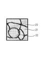
- the sliding member 1 includes a coating 2 including a hard metal material particle 22 and a corrosion-resistant metal material particle 21 having a lower hardness than the hard metal material particle 22 on a base material 3.
- the cross section of No. 2 shows that the hard metal material particles 22 are dispersed in the form of islands in the particle mass of the corrosion-resistant metal material particles 21.
- the particle mass means that the surface of the particles forming the coating is locally melted and solidified, and the particles of the entire coating are combined and integrated, and the above-mentioned particles are not completely integrated. It refers to an aggregate of particles forming an interface, and does not refer to an aggregate that is completely integrated by completely melting or melting and solidifying the particles.
- the corrosion-resistant metal material particles are made of a metal material having more excellent corrosion resistance than iron, and include at least one metal selected from the group consisting of copper (Cu), cobalt (Co), chromium (Cr), and nickel (Ni); Alternatively, it is made of an alloy containing the metal.
- chromium is a metal having a greater ionization tendency than iron, chromium is not only an alloy containing chromium such as stainless steel but also a simple metal because it forms a passivated oxide film of Cr 2 O 3 on the surface. Even it has excellent corrosion resistance.
- an alloy containing 50% by mass or more of copper can be preferably used because of its high spontaneous potential and excellent corrosion resistance.
- Cu—Ni—Si alloy, Cu—Co—Si alloy, Cu -Ag alloy, Cu-Al alloy, Cu-Ni alloy, Cu-Ti alloy, and the like can be preferably used because of its high spontaneous potential and excellent corrosion resistance.
- Cu—Ni—Si alloy, Cu—Co—Si alloy, Cu -Ag alloy, Cu-Al alloy, Cu-Ni alloy, Cu-Ti alloy, and the like can be preferably used because of its high spontaneous potential and excellent corrosion resistance.
- Si diffuses into the surface to form an oxide film of SiO 2 , and the oxide film acts like a passivation film. It can be preferably used to improve corrosion resistance.
- the film has a sea-island structure in which the cross section of the hard metal material particles is dispersed in an island shape in a particle mass of the corrosion-resistant metal material particles, and most of the hard metal material particles are covered with the corrosion-resistant metal material particles, Since it is not exposed on the inner surface of the pores inside the coating, corrosion occurring inside the coating can be prevented.
- a soft metal material generally has a low melting point and is easily melted and strongly bonded. Since the corrosion-resistant metal material particles are lower in hardness than the hard metal material particles described below and have a Vickers hardness of less than 600 Hv, when forming the particle mass, the corrosion-resistant metal material particles are strongly bonded to each other, and the strength and strength of the coating are improved. The wear resistance is improved.
- the lower limit of the Vickers hardness of the corrosion-resistant metal material particles is not particularly limited, but when it is 80 Hv or more, the wear resistance is improved.
- the area ratio of the corrosion-resistant metal material particles in the cross section is 30% or more, preferably 50% or more, more preferably 80% or more.
- the hard metal material particles are particles having a higher hardness than the corrosion-resistant metal material particles, and may be used as long as they contain particles having a Vickers hardness of 600 Hv or more. In order to form a local battery with the metal material particles, it is preferable to include the same type of metal material as the corrosion-resistant metal material particles.
- At least one metal selected from the group consisting of cobalt (Co), chromium (Cr), and nickel (Ni), or an alloy containing the metal can be used.
- the alloy examples include hard cobalt-based alloys such as TRIBALOY (registered trademark) T-400 and STELLITE (registered trademark) 6, TRIBAROY (registered trademark) T-700, and Ni700 (registered trademark) (Ni-32Mo-16Cr). -3.1Si) and the like.
- hard cobalt-based alloys such as TRIBALOY (registered trademark) T-400 and STELLITE (registered trademark) 6, TRIBAROY (registered trademark) T-700, and Ni700 (registered trademark) (Ni-32Mo-16Cr). -3.1Si) and the like.
- the Vickers hardness of the hard metal material particles is preferably 700 Hv or more and 1500 Hv or less. When the Vickers hardness of the hard metal material particles is in the above range, both abrasion resistance and counterpart aggression can be achieved.
- the area ratio of the hard metal material particles in the cross section of the coating is preferably 5% or more and 50% or less, more preferably 5% or more and 30% or less, and preferably 10% or more and 15% or less. More preferred.
- the coating may have an amorphous layer 23 at at least a part of the interface between the corrosion-resistant metal material particles 21 and the interface between the corrosion-resistant metal material particle 21 and the hard metal material particle 22. preferable.
- Amorphous has a random structure with no regular arrangement of atoms like crystals, is homogeneous and isotropic without inclusions and segregation, and has lattice defects such as grain boundaries and dislocations, which are the starting points of corrosion. As a result, corrosion resistance is generally excellent.
- the interface between the particles forming the coating that is, having an amorphous on the surface of the particles, improves the corrosion resistance of the particles themselves, and even if there is a void between the particles, the inside of the coating The generation of corrosion from steel can be suppressed.
- the above amorphous can be formed by forming a film by a cold spray method described later.
- the average particle size of the crystal grains in the particles is preferably 10 ⁇ m or less, and more preferably 5 ⁇ m or less. When the crystal grains in the particles are fine, the film strength is improved.
- the amorphous at the particle interface and the crystal grains in the particles project a diffraction pattern on the detector surface by electron beam back scattering diffraction (EBSD) using a scanning electron microscope (SEM), and determine the crystal orientation from the projected pattern. It can be confirmed by analysis.
- EBSD electron beam back scattering diffraction
- SEM scanning electron microscope
- the coating preferably has a cross-sectional porosity of 10 area% or less, and more preferably 5 area% or less.
- the pores are small and dense, condensed water hardly accumulates in the coating film and crevice corrosion hardly occurs, so that a decrease in wear resistance can be suppressed over a long period of time.
- the coating preferably has few pores. However, when the coating is a sintered body and the pores inevitably occur, the pores are preferably independent pores. Since the pores are independent, condensed water does not enter the pores inside the coating, and an oxygen concentration cell is not formed inside the coating, thereby suppressing the occurrence of crevice corrosion.
- the area ratio of the corrosion-resistant metal material particles, the area ratio of the hard metal material particles, and the porosity in the cross section of the coating film are calculated by binarizing a scanning electron microscope image (SEM image) by image processing and performing image analysis. Can be.
- SEM image scanning electron microscope image
- the average particle size (equivalent circle diameter: diameter of a circle having the same area as the projected area of the particle image) of the corrosion-resistant metal material particles and the hard metal material particles in the cross section of the coating is preferably 5 ⁇ m to 100 ⁇ m, and more preferably 5 ⁇ m. It is preferably about 40 ⁇ m.
- a dense coating can be formed by the small average particle size of the particles, but if the particle size is too small, the kinetic energy of the particles will be small in the cold spray method described below, and the particles will be less likely to be plastically deformed. In some cases, the film properties may decrease and the coating strength may decrease.
- the natural potential of the coating is preferably -600 mV or more, more preferably 0 mV or more.
- the thickness of the coating depends on the temperature at the place where the sliding member is used and the sliding environment, but is preferably, for example, 0.05 to 5.0 mm, and 0.1 to 2.0 mm. Is more preferred.
- the thickness is less than 0.05 mm, the strength of the coating film itself is insufficient, and when the strength of the base material is low, plastic deformation may occur. On the other hand, when the thickness exceeds 10 mm, the coating may be easily peeled off due to the relationship between the residual stress generated at the time of film formation and the interface adhesion.
- the relative difference in the natural potential between the film and the substrate is 1100 mV or less. Since the natural potential difference between the coating and the substrate is small, contact corrosion between different metals can be prevented.
- the substrate is not particularly limited, and metals conventionally used as sliding members for internal combustion engines can be used, but aluminum alloys are preferably used because of their high thermal conductivity.
- Examples of the aluminum alloy include AC2A, AC8A, and ADC12 specified by Japanese Industrial Standards.
- the sliding member has excellent corrosion resistance and wear resistance, and can be suitably used for, for example, a piston, a piston ring, a piston pin, a cylinder, a crankshaft, a camshaft, and a valve lifter.
- the sliding member may be formed by spraying mixed particles of corrosion-resistant metal material particles and hard metal material particles onto a base material surface by cold spray to form a coating, or by sintering a compact obtained by solidifying the mixed particles. It can be manufactured by, for example, a method in which the compact is pressed into a base material.
- Cold spraying is a method of forming a coating by colliding a substrate in a solid state in a supersonic flow with an inert gas without melting or gasifying the metal particles of the material. Unlike a method of forming a film by melting, it is possible to minimize the change in characteristics of the metal particles due to heat and oxidation in the film.
- the metal particles in the solid state collide with the base material, the metal particles themselves are plastically deformed, and a part of the kinetic energy is converted into heat energy, and the surface of the metal particles is locally melted and solidified. As a result, the metal particles are bonded to each other to form a film.
- the surface of the locally melted metal particles is quenched to form amorphous at the interface between the particles and the metal particles. Is plastically deformed and the crystal grains in the metal particles are refined.
- the relatively soft corrosion-resistant metal material particles are plastically deformed, deposited without gaps and bonded, and amorphous at the interface between the particles.
- a coating film in which the hard metal material particles are dispersed in an island shape in the particle mass is formed.
- the speed at which the mixed particles are sprayed is preferably 300 to 1200 m / s, and more preferably 500 to 1000 m / s.
- the pressure of the working gas for spraying the mixed particles is preferably 2 to 5 MPa, more preferably 3.5 to 5 MPa. If the pressure of the working gas is less than 2 MPa, the particle velocity cannot be obtained, and the porosity may increase.
- the temperature of the working gas depends on the mixed particles, but is preferably 400 to 800 ° C., and more preferably 600 to 800 ° C. If the temperature of the working gas is lower than 400 ° C., the corrosion-resistant metal material particles are unlikely to undergo plastic deformation, the porosity increases, and the corrosion resistance may decrease. On the other hand, when the temperature of the working gas exceeds 800 ° C., the corrosion-resistant metal material particles colliding with the base material become too soft, the residual stress becomes small, and the coating may be easily peeled off.
- working gas examples include a nitrogen gas and a helium gas. These may be used alone or as a mixture.
- the sintering is a method in which a compact formed by solidifying metal particles is baked and solidified at a temperature lower than the temperature at which the metal particles are melted. Can be reduced. Therefore, by strongly processing the metal particles to refine the crystal grains in the metal particles, the crystal grains in the metal particles are refined, and a high-strength film can be formed.
- the molded body obtained by solidifying the metal particles is formed by putting the metal particles into a mold, compression molding, or molding a pellet obtained by kneading the metal particles and a binder in the same manner as plastic injection molding, and removing the binder by heating or the like. That is, it can be formed by a so-called metal powder injection molding method.
- the temperature for sintering the compact is preferably 900 ° C to 1100 ° C, depending on the type of the mixed particles.
- Example 1 In the completed state of the seating portion of the engine valve in the cylinder head, assuming a target coating thickness of 0.2 mm, the aluminum base material (Japanese Industrial Standard H 4040 A5056) is pre-processed to form a groove. Produced.
- Japanese Industrial Standard H 4040 A5056 Japanese Industrial Standard H 4040 A5056
- MI After injection molding of MIM raw material pellets containing the following mixed particles and binder, a degreased ⁇ 40 ⁇ L14 mm degreased body by heating was heated at 1000 ° C. for 1 hour to obtain a sintered body.
- Corrosion-resistant metal material particles CaF 2 added hard-worked Cu-2.9Ni-0.7Si alloy particles (average particle size 10 ⁇ m)
- Hard metal material particles Heavy-worked Co alloy particles (Triballoy T-400 manufactured by Kennametal Co., Ltd .: average particle size 45 ⁇ m)
- the sintered body was cut into a valve seat shape, pressed into the groove of the aluminum base, and finished into a shape of a seating portion of an engine valve by machining to obtain a sliding member having a coating thickness of 0.5 mm.
- Example 2 The following mixed particles were cold sprayed under the following conditions while rotating the aluminum substrate to form a film having a thickness of 1 mm.
- Corrosion-resistant metal material particles Cu-2.9Ni-0.7Si alloy particles (average particle size 30 ⁇ m)
- Hard metal material particles Co alloy particles (Triballoy T-400 manufactured by Kennametal Co., Ltd .: average particle size 45 ⁇ m)
- High-pressure cold spray device Kinetiks 4000, manufactured by CGT Working gas: Nitrogen gas Gas temperature: 600 ° C, Gas pressure: 4 MPa, Particle velocity: 680-720 m / s
- the aluminum substrate on which the coating was formed was finished into a shape of a seating portion of an engine valve of a cylinder head by machining to obtain a sliding member having a coating thickness of 0.5 mm.
- Example 3 A sliding member was obtained in the same manner as in Example 2, except that the following mixed particles were cold sprayed under the following conditions while rotating the aluminum substrate.
- Corrosion-resistant metal material particles Cu-2.9Ni-0.7Si alloy particles (average particle size 30 ⁇ m) Hard metal material particles: Fe alloy particles (SKH51: average particle size 45 ⁇ m) Corrosion resistant metal material particles / hard metal material particles (volume ratio): 80/18
- High-pressure cold spray device Kinetiks 4000, manufactured by CGT Working gas: Nitrogen gas Gas temperature: 600 ° C, Gas pressure: 3.5 MPa, Particle velocity: 650-690 m / s
- Example 4 A sliding member was obtained in the same manner as in Example 2, except that the following mixed particles were cold sprayed under the following conditions while rotating the aluminum substrate.
- Corrosion resistant metal material particles SUS440C particles (average particle size 30 ⁇ m)
- Hard metal material particles Co alloy particles (Triballoy T-400 manufactured by Kennametal Co., Ltd .: average particle size 45 ⁇ m)
- High-pressure cold spray device Kinetiks 4000, manufactured by CGT Working gas: Nitrogen gas Gas temperature: 750 ° C, Gas pressure: 4 MPa, Particle speed: 740 to 780 m / s
- Example 5 The following mixed particles were placed in a ⁇ 40 mold and molded at 1000 kN, and a ⁇ 40 ⁇ L14 mm compression molded body was heated at 1000 ° C. for 1 hour to obtain a sintered body.
- Corrosion-resistant metal material particles Cu-2.9Ni-0.7Si alloy particles with CaF 2 added (average particle size 80 ⁇ m)
- Hard metal material particles Ni alloy particles (Triballoy T-700, manufactured by Kennametal): average particle size 45 ⁇ m
- the sintered body was cut into a valve seat shape, pressed into the groove of the aluminum base, and finished into a shape of a seating portion of an engine valve by machining to obtain a sliding member having a coating thickness of 0.5 mm.
- Example 6 A sliding member was obtained in the same manner as in Example 5, except that the following mixed particles were used.
- Corrosion-resistant metal material particles Cu-2.9Ni-0.7Si alloy particles with CaF 2 added (average particle size 80 ⁇ m)
- Hard metal material particles Co alloy particles (Triballoy T-400 manufactured by Kennametal Co., Ltd .: average particle size 45 ⁇ m)
- Example 7 A sliding member was obtained in the same manner as in Example 5, except that the following mixed particles were used.
- Corrosion-resistant metal material particles Cu-2.9Ni-0.7Si alloy particles with CaF 2 added (average particle size 80 ⁇ m)
- Hard metal material particles Fe alloy particles (SKH51: average particle size 45 ⁇ m)
- Example 8 A sliding member was obtained in the same manner as in Example 5, except that the following mixed particles were used.
- Corrosion-resistant metal material particles Cu-2.9Ni-0.7Si alloy particles with CaF 2 added (average particle size 80 ⁇ m)
- Hard metal material particles Fe alloy particles (SKH51: average particle size 45 ⁇ m)
- Corrosion resistant metal material particles Cu alloy particles (average particle size 80 ⁇ m)
- Hard metal material particles Co alloy particles (Triballoy T-400 manufactured by Kennametal Co., Ltd .: average particle size 45 ⁇ m)
- Hard metal material particles Fe + graphite-diffused Fe alloy particles (average particle size 45 ⁇ m)
- Example 5 A sliding member was obtained in the same manner as in Example 5 except that copper for infiltration was arranged on the upper part of the compression molded body, and a sintered body heated at 1000 ° C for one hour in an ammonia decomposition gas atmosphere was used.
- Example 2 A sliding member was obtained in the same manner as in Example 5, except that the following mixed particles were used.
- Corrosion-resistant metal material particles Cu-2.9Ni-0.7Si alloy particles with CaF 2 added (average particle size 80 ⁇ m)
- Example 3 A sliding member was obtained in the same manner as in Example 5, except that the following mixed particles were used.
- Corrosion resistant metal material particles Cu alloy particles (average particle size 80 ⁇ m)
- Hard metal material particles Co alloy particles (Triballoy T-400 manufactured by Kennametal Co., Ltd .: average particle size 45 ⁇ m)
- Hard metal material particles Fe + graphite-diffused Fe alloy particles (average particle size 45 ⁇ m)
- Example 4 A sliding member was obtained in the same manner as in Example 5, except that the following mixed particles were used.
- Hard metal material particles Co alloy particles (Triballoy T-400 manufactured by Kennametal Co., Ltd .: average particle size 45 ⁇ m)
- Hard metal material particles Fe + graphite-diffused Fe alloy particles (average particle size 45 ⁇ m)
- Example 5 A sliding member was obtained in the same manner as in Example 5, except that the following mixed particles were used.
- Hard metal material particles Co alloy particles (Triballoy T-400 manufactured by Kennametal Co., Ltd .: average particle size 45 ⁇ m)
- Hard metal material particles Fe + graphite-diffused Fe alloy particles (average particle size 45 ⁇ m)
- FIG. 3 shows a cross-sectional SEM image of the sliding member of the second embodiment.
- the Vickers hardness of the corrosion-resistant metal material particle portion and the hard metal material particle portion in the coating was measured and calculated based on a Vickers hardness test (JIS Z 2244).
- a film is formed on the surface of the aluminum alloy base material with a thickness of 8 mm, and the coating part is cut out. ⁇ 15 mm
- One side of a 5 mm thick sample is polished on one side with a # 1000 water-resistant paper, leaving a ⁇ 10 mm square sample electrode.
- the self potential was measured in 0.5 wt% nitric acid (25 ° C.) using platinum as a counter electrode.
- Weight resistance Using a valve seat wear tester manufactured by Takachiho Seiki Co., Ltd., the wear amount of the sliding member after the corrosion resistance test was measured under the following conditions. Specifically, the shape of the seating portion of the engine valve in the cylinder head before and after the test is acquired using a shape measuring device, the amount of wear at four locations is measured, and the average value is calculated. Amount.
- Mating valve material SUH35 Test temperature: 300 ° C Vertical speed: 3000 times / min Valve rotation speed: 5 rpm Seating frequency: 540000 times
- the sliding member of the embodiment in which the hard metal particles are dispersed in the form of islands in the particle mass of the corrosion-resistant metal particles and the area ratio of the corrosion-resistant metal material particles is 30% or more. It can be seen that the sample has excellent corrosion resistance and excellent wear resistance over time as compared with the sliding member of the comparative example. Further, the sliding members of Examples 2 to 4 having an amorphous surface at the interface between the particles have excellent corrosion resistance as compared with the sliding members of Examples 5 to 8, and have an amorphous state at the interface between the particles, so that the coating in the coating film can be obtained. It has been confirmed that corrosion can be prevented even if condensed water infiltrates into the water. Further, it can be seen that in the sliding members of Examples 2 to 4, the corrosion-resistant metal material particles are plastically deformed during the formation of the film, the crystals in the particles are refined, and a high-hardness film can be formed.
Landscapes
- Engineering & Computer Science (AREA)
- Chemical & Material Sciences (AREA)
- Mechanical Engineering (AREA)
- General Engineering & Computer Science (AREA)
- Metallurgy (AREA)
- Materials Engineering (AREA)
- Organic Chemistry (AREA)
- Chemical Kinetics & Catalysis (AREA)
- Manufacturing & Machinery (AREA)
- Composite Materials (AREA)
- Powder Metallurgy (AREA)
- Sliding-Contact Bearings (AREA)
- Other Surface Treatments For Metallic Materials (AREA)
Abstract
本発明の摺動部材は、基材上に被膜を備える。 そして、上記被膜が、硬質金属材粒子と該硬質金属材粒子よりも硬度が低い耐食性金属材粒子とを含み、 上記硬質金属材粒子が、少なくともビッカース硬度が600Hv以上の粒子を含有し、 上記耐食性金属材粒子が、銅(Cu)、コバルト(Co)、クロム(Cr)、及びニッケル(Ni)から成る群から選ばれた少なくとも一種の金属、または該金属を含む合金から成り、 上記被膜の断面が、上記耐食性金属材粒子の粒子塊中に上記硬質金属材粒子が島状に分散し、上記耐食性金属材粒子の面積率が30%以上であるため、被膜内部の硬質金属材粒子の腐食が防止されて、長期に亘り耐摩耗性が維持された摺動部材を提供することができる。
Description
本発明は、摺動部材に係り、更に詳細には、硬質金属材粒子を含有し耐摩耗性が向上した摺動部材に関する。
自動車などの内燃機関に用いられる摺動部材は、耐摩耗性に優れ、かつ相手攻撃性も小さいことが要求される。
特許文献1の日本国特開平6-179937号公報には、鉄系合金のマルテンサイト組織中に、硬質合金粒子、固体潤滑剤およびセラミックス粒子を分散させて、耐摩耗性を向上させ、かつ相手攻撃性を小さくしたバルブシート用焼結合金が開示されている。
しかしながら、一般的に焼結合金は材料の合金粒子間に多数の空孔を有し、摺動部材内部の空孔で腐食が生じると、空孔内は摺動面とは異なり新生面が更新されないため、腐食が進行して粒子同士が結合している粒界付近を腐食させるに至り、粒子同士の結合強度が低下し、耐摩耗性が低下してしまう。
近年においては、省燃費化の要求から断続運転の割合が多くなっており、排気ガス等に含まれる水分が凝縮した凝縮水が空孔内に滞留し易く、この凝縮水と排気ガス中に含まれる窒素酸化物や硫黄酸化物とが反応して上記空孔内で酸が生成される。
また、焼結合金の合金粒子間に形成される空孔が狭小であるため、被膜内部に酸素濃淡電池が形成され、上記空孔が腐食の起点となって被膜内部で腐食が進行し、耐摩耗性を低下させる。
また、焼結合金の合金粒子間に形成される空孔が狭小であるため、被膜内部に酸素濃淡電池が形成され、上記空孔が腐食の起点となって被膜内部で腐食が進行し、耐摩耗性を低下させる。
したがって、内燃機関に用いられる摺動部材は、耐摩耗性や相手攻撃性だけでなく、耐腐食性をも向上させる必要がある。
本発明は、このような従来技術の有する課題に鑑みてなされたものであり、その目的とするところは、耐腐食性が高く経時による耐摩耗性の低下が防止された摺動部材を提供することにある。
本発明者は、上記目的を達成すべく鋭意検討を重ねた結果、硬質金属材粒子の大半を耐食性金属材粒子で覆うことにより、上記目的が達成できることを見出し、本発明を完成するに至った。
即ち、本発明の摺動部材は、基材上に被膜を備える。
そして、上記被膜が、硬質金属材粒子と該硬質金属材粒子よりも硬度が低い耐食性金属材粒子とを含み、
上記硬質金属材粒子が、少なくともビッカース硬度が600Hv以上の粒子を含有し、
上記耐食性金属材粒子が、銅(Cu)、コバルト(Co)、クロム(Cr)、及びニッケル(Ni)から成る群から選ばれた少なくとも一種の金属、または該金属を含む合金から成り、
上記被膜の断面が、上記耐食性金属材粒子の粒子塊中に上記硬質金属材粒子が島状に分散し、上記耐食性金属材粒子の面積率が30%以上であることを特徴とする。
そして、上記被膜が、硬質金属材粒子と該硬質金属材粒子よりも硬度が低い耐食性金属材粒子とを含み、
上記硬質金属材粒子が、少なくともビッカース硬度が600Hv以上の粒子を含有し、
上記耐食性金属材粒子が、銅(Cu)、コバルト(Co)、クロム(Cr)、及びニッケル(Ni)から成る群から選ばれた少なくとも一種の金属、または該金属を含む合金から成り、
上記被膜の断面が、上記耐食性金属材粒子の粒子塊中に上記硬質金属材粒子が島状に分散し、上記耐食性金属材粒子の面積率が30%以上であることを特徴とする。
本発明によれば、耐食性金属材粒子の粒子塊中に硬質金属材粒子を島状に分散させることとしたため、被膜内部の硬質金属材粒子の腐食が防止されて、長期に亘り耐摩耗性が維持された摺動部材を提供することができる。
<摺動部材>
本発明の摺動部材について詳細に説明する。
上記摺動部材1は、図1に示すように、硬質金属材粒子22と該硬質金属材粒子22よりも硬度が低い耐食性金属材粒子21を含む被膜2を基材3上に備え、上記被膜2の断面が、上記耐食性金属材粒子21の粒子塊中に上記硬質金属材粒子22が島状に分散している。
本発明の摺動部材について詳細に説明する。
上記摺動部材1は、図1に示すように、硬質金属材粒子22と該硬質金属材粒子22よりも硬度が低い耐食性金属材粒子21を含む被膜2を基材3上に備え、上記被膜2の断面が、上記耐食性金属材粒子21の粒子塊中に上記硬質金属材粒子22が島状に分散している。
本発明において粒子塊とは、被膜を形成する粒子の表面が局所的に溶融して固化し、被膜全体の粒子同士が結合して一体化しており、上記粒子同士が渾然一体とはならずに界面を形成している粒子の集合体をいい、粒子が完全に溶融又は溶解し固化することで渾然一体となった集合体をいわない。
上記耐食性金属材粒子は、鉄よりも耐食性が優れる金属材で成り、銅(Cu)、コバルト(Co)、クロム(Cr)、及びニッケル(Ni)から成る群から選ばれた少なくとも一種の金属、または該金属を含む合金から成る。
なお、クロムは、鉄よりもイオン化傾向が大きい金属であるが、表面に不動態であるCr2O3の酸化被膜を形成するため、ステンレスのようなクロムを含む合金だけでなく金属単体であっても耐食性が優れる。
なお、クロムは、鉄よりもイオン化傾向が大きい金属であるが、表面に不動態であるCr2O3の酸化被膜を形成するため、ステンレスのようなクロムを含む合金だけでなく金属単体であっても耐食性が優れる。
上記合金としては、例えば、銅を50質量%以上含有する合金は、自然電位が高く耐食性に優れるため好ましく使用することができ、例えば、Cu-Ni-Si合金、Cu-Co-Si合金、Cu-Ag合金や、Cu-Al合金、Cu-Ni合金、Cu-Ti合金などを挙げることができる。
特に、Cu-Ni-Si合金やCu-Co-Si合金などのSiを含む合金は、表面にSiが拡散してSiO2の酸化被膜を形成し、該酸化被膜が不動態膜のようにふるまって耐腐食性を向上させるため、好ましく使用できる。
上記被膜は、その断面が耐食性金属材粒子の粒子塊中に硬質金属材粒子が島状に分散した海島構造を形成しており、硬質金属材粒子の大半が耐食性金属材粒子で覆われて、被膜内部の空孔の内表面に露出していないため、被膜内部で生じる腐食を防止できる。
また、軟らかい金属材料は一般的に融点が低く容易に溶融して強固に結合する。上記耐食性金属材粒子は、後述する硬質金属材粒子よりも硬度が低く、ビッカース硬度が600Hv未満であることから、粒子塊形成の際、耐食性金属材粒子同士が強固に結合し、被膜の強度や耐摩耗性が向上する。
上記耐食性金属材粒子のビッカース硬度の下限は、特に制限はないが80Hv以上であることで、耐摩耗性が向上する。
上記耐食性金属材粒子のビッカース硬度の下限は、特に制限はないが80Hv以上であることで、耐摩耗性が向上する。
上記被膜は、断面の耐食性金属材粒子の面積率が30%以上であり、さらに50%以上であることが好ましく、80%以上であることがより好ましい。耐食性金属材粒子の面積率が大きくなることで、硬質金属材粒子を覆って耐食性が向上すると共に、耐食性金属材粒子同士が強固に結合して被膜強度が向上する。
上記硬質金属材粒子としては、上記耐食性金属材粒子よりも高硬度の粒子であり、ビッカース硬度が600Hv以上の粒子を含有すれば使用できるが、被膜中で上記耐食性金属材粒子と接触し、耐食性金属材粒子との間で局部電池を形成するため、耐食性金属材粒子と同種の金属材を含むことが好ましい。
具体的には、コバルト(Co)、クロム(Cr)、及びニッケル(Ni)から成る群から選ばれた少なくとも一種の金属、又は該金属を含む合金を使用できる。
上記合金としては、例えば、TRIBALOY(登録商標)T-400、Stellite(登録商標)6などの硬質コバルト基合金や、TRIBALOY(登録商標)T-700、Ni700(登録商標)(Ni-32Mo-16Cr-3.1Si)などの硬質ニッケル基合金を挙げることができる。
上記硬質金属材粒子のビッカース硬度は、さらに700Hv以上1500Hv以下であることが好ましい。硬質金属材粒子のビッカース硬度が上記範囲であることで耐摩耗性と相手攻撃性とを両立させることができる。
上記被膜は、その断面の硬質金属材粒子の面積率が5%以上50%以下であることが好ましく、さらに5%以上30%以下であることが好ましく、10%以上15%以下であることがより好ましい。
硬質金属材粒子の面積率が上記範囲であることで、上記耐食性金属材粒子と相俟って耐摩耗性が向上すると共に被膜強度が向上する。
上記被膜は、図2に示すように、上記耐食性金属材粒子21同士の界面、及び、上記耐食性金属材粒子21と上記硬質金属材粒子22との界面の少なくとも一部にアモルファス23を有することが好ましい。
アモルファスは、結晶のような原子の規則的な配列がないランダムな構造であり、介在物や偏析がなく均質かつ等方的であり、腐食の起点となる結晶粒界や転位などの格子欠陥がないため、一般に耐食性が優れる。
上記被膜を形成する粒子同士の界面、すなわち、上記粒子の表面にアモルファスを有することで、粒子自体の耐食性が向上し、粒子と粒子との間に空孔を有する場合であっても、被膜内部からの腐食の発生を抑制できる。
上記アモルファスは、後述するコールドスプレー法で成膜することで形成できる。
また、上記粒子中の結晶粒の平均粒径は、10μm以下であることが好ましく、5μm以下であることが好ましい。粒子中の結晶粒が微細であることで、被膜強度が向上する。
上記粒子界面のアモルファスや粒子中の結晶粒は、走査電子顕微鏡(SEM)による電子線後方散乱回折(EBSD)により、回折パターンを検出器面上に投影し、その投影されたパターンから結晶方位を解析することで確認できる。
上記被膜は、断面の空孔率が10面積%以下であることが好ましく、5面積%以下であることが好ましい。空孔が少なく密実であることで被膜中に凝縮水が溜まり難くなり、また隙間腐食が生じ難くなって、長期に亘り耐摩耗性の低下を抑制できる。
上記被膜は、空孔が少ないことが好ましいが、被膜が焼結体である場合など、空孔が不可避的に生じる場合は空孔が独立孔であることが好ましい。空孔が独立していることで、被膜内部の空孔に凝縮水が侵入することがなく、また被膜内部で酸素濃淡電池が形成されず隙間腐食の発生が抑制される。
上記被膜の断面における耐食性金属材粒子の面積率、硬質金属材粒子の面積率、及び空孔率は、走査型電子顕微鏡像(SEM像)を画像処理により2値化し、画像解析により算出することができる。
上記被膜の断面における耐食性金属材粒子及び硬質金属材粒子の平均粒径(円相当径:粒子像の投影面積と同じ面積を持つ円の直径)は、5μm~100μmであることが好ましく、さらに5μm~40μmであることが好ましい。
粒子の平均粒径が小さいことで密実な被膜を形成できるが、粒子径が小さすぎると後述するコールドスプレー法では粒子の運動エネルギーが小さくなって粒子が塑性変形し難くなり、粒子同士の密着性が低下して被膜強度が低下することがある。
上記被膜の自然電位は、-600mV以上であることが好ましく、0mV以上であることがより好ましい。被膜の自然電位が高いことで、腐食が進み難く長期に亘り耐摩耗性の低下を抑制できる。
上記被膜の厚さは、摺動部材が用いられる箇所の温度や摺動環境にもよるが、例えば、0.05~5.0mmとすることが好ましく、0.1~2.0mmとすることがより好ましい。
0.05mm未満であると、被膜自体の強度が不足し、基材の強度が低い場合に塑性変形を起こすことがある。また、10mmを超えると、成膜時に発生する残留応力と界面密着力の関係により被膜が剥離し易くなることがある。
また、上記被膜と上記基材との自然電位の相対差は、1100mV以下であることが好ましい。被膜と基材との自然電位差が小さいことで異種金属間の接触腐食を防止できる。
上記基材としては、特に制限はなく、内燃機関の摺動部材として従来から用いられている金属を使用できるがアルミ合金は熱伝導性が高く好ましく使用できる。
上記アルミ合金としては、例えば、日本工業規格で規定されているAC2A、AC8A、ADC12などを挙げることができる。
上記摺動部材は、耐食性及び耐摩耗性に優れ、例えば、ピストン、ピストンリング、ピストンピン、シリンダ、クランクシャフト、カムシャフト、及び、バルブリフタなどに好適に使用できる。
<摺動部材の製造方法>
上記摺動部材は、コールドスプレーにより、耐食性金属材粒子と硬質金属材粒子との混合粒子を基材表面に吹き付けて被膜を形成する方法や、上記混合粒子を固めた成形体を焼結した焼結体を基材に圧入する方法等により製造することができる。
上記摺動部材は、コールドスプレーにより、耐食性金属材粒子と硬質金属材粒子との混合粒子を基材表面に吹き付けて被膜を形成する方法や、上記混合粒子を固めた成形体を焼結した焼結体を基材に圧入する方法等により製造することができる。
コールドスプレーは、材料の金属粒子を溶融またはガス化させることなく不活性ガスと共に超音速流で固相状態のまま基材に衝突させて被膜を形成する方法であり、溶射法などの金属粒子を溶融させて被膜を形成する方法とは異なり、熱による金属粒子の特性変化、被膜中の酸化を最小限にすることができる。
上記コールドスプレーにより、固相状態の金属粒子が基材に衝突すると金属粒子自体が塑性変形すると共に、運動エネルギーの一部が熱エネルギーに変換されて金属粒子の表面が局所的に溶融し固化することで金属粒子同士が結合して被膜が形成される。
このとき、基材及び金属粒子の温度が上記金属粒子の融点以下であるため、局所的に溶融した金属粒子の表面が急冷されて粒子と粒子との界面にアモルファスが形成される共に、金属粒子が塑性変形して金属粒子中の結晶粒が微細化される。
本発明においては、耐食性金属材粒子と硬質金属材粒子との混合粒子を吹き付けるため、比較的軟らかい耐食性金属材粒子が塑性変形して隙間なく堆積して結合し、粒子と粒子との界面にアモルファスを有する耐食性金属材粒子の粒子塊を形成する。そして、硬質金属材粒子が上記粒子塊にめり込むため、上記粒子塊中に上記硬質金属材粒子が島状に分散した被膜が形成される。
上記混合粒子を吹き付ける速度は、300~1200m/sであることが好ましく、500~1000m/sとであることが好ましい。
また、上記混同粒子を吹き付ける作動ガスの圧力は、2~5MPaであることが好ましく、3.5~5MPaであることがより好ましい。作動ガスの圧力が2MPa未満であると、粒子速度が得られず、空孔率が大きくなることがある。
また、作動ガスの温度は、混合粒子にもよるが、400~800℃であることが好ましく、600~800℃であることがより好ましい。
作動ガスの温度が400℃未満であると、耐食性金属材粒子が塑性変形し難く空孔率が大きくなって耐食性が低下することがある。また、作動ガスの温度が800℃を超えると、基材に衝突する耐食性金属材粒子が軟らかくなり過ぎ、残留応力が小さくなって被膜が剥離し易くなることがある。
作動ガスの温度が400℃未満であると、耐食性金属材粒子が塑性変形し難く空孔率が大きくなって耐食性が低下することがある。また、作動ガスの温度が800℃を超えると、基材に衝突する耐食性金属材粒子が軟らかくなり過ぎ、残留応力が小さくなって被膜が剥離し易くなることがある。
上記、作動ガスとしては、例えば、窒素ガス、ヘリウムガスなどを挙げることができ、これらは、1種を単独で用いてもよく、混合して用いてもよい。
また、上記焼結は、金属粒子を固めた成形体を上記金属粒子が溶融する温度より低い温度で焼き固める方法であり、金属粒子を溶融させずに結合させるため、熱による金属粒子の特性変化を減少させることができる。したがって、金属粒子を強加工し、金属粒子中の結晶粒を微細化しておくことで、金属粒子中の結晶粒が微細化し、高強度の被膜を形成できる。
上記金属粒子を固めた成形体は、金属粒子を型に入れて圧縮成形法や、また金属粒子とバインダーとを混練したペレットをプラスチックの射出成形と同様の方法で成形し加熱等によりバインダーを除去する、所謂、金属粉末射出成型法により形成することができる。
上記成形体を焼結する温度は、混合粒子の種類にもよるが900℃~1100℃であることが好ましい。
以下、本発明を実施例により詳細に説明するが、本発明は下記実施例に限定されるものではない。
[実施例1]
シリンダヘッドにおけるエンジンバルブの着座部の加工完了状態で、狙い被膜厚み0.2mmを想定して、アルミニウム基材(日本工業規格 H 4040 A5056)に溝形成の前加工を行って、アルミニウム基材を作製した。
シリンダヘッドにおけるエンジンバルブの着座部の加工完了状態で、狙い被膜厚み0.2mmを想定して、アルミニウム基材(日本工業規格 H 4040 A5056)に溝形成の前加工を行って、アルミニウム基材を作製した。
以下の混合粒子とバインダーとを含有するMIM原料ペレットを射出成形した後、加熱して脱脂したφ40×L14mmの脱脂体を1000℃で1時間加熱して焼結体を得た。
耐食性金属材粒子:CaF2添加強加工Cu-2.9Ni-0.7Si合金粒子(平均粒径10μm)
硬質金属材粒子:強加工Co合金粒子(Kennametal社製 Tribaloy T-400:平均粒径45μm)
耐食性金属材粒子/硬質金属材粒子(体積比):89/10
硬質金属材粒子:強加工Co合金粒子(Kennametal社製 Tribaloy T-400:平均粒径45μm)
耐食性金属材粒子/硬質金属材粒子(体積比):89/10
上記焼結体をバルブシート形状に切り出し、上記アルミニウム基材の溝に圧入し、機械加工によりエンジンバルブの着座部の形状に仕上げ、被膜の厚さが0.5mmの摺動部材を得た。
[実施例2]
以下の混合粒子を、上記アルミニウム基材を回転させながらに下記条件でコールドスプレーし、厚さ1mmの被膜を形成した。
以下の混合粒子を、上記アルミニウム基材を回転させながらに下記条件でコールドスプレーし、厚さ1mmの被膜を形成した。
耐食性金属材粒子:Cu-2.9Ni-0.7Si合金粒子(平均粒径30μm)
硬質金属材粒子:Co合金粒子(Kennametal社製 Tribaloy T-400:平均粒径45μm)
耐食性金属材粒子/硬質金属材粒子(体積比):89/10
硬質金属材粒子:Co合金粒子(Kennametal社製 Tribaloy T-400:平均粒径45μm)
耐食性金属材粒子/硬質金属材粒子(体積比):89/10
高圧型コールドスプレー装置:CGT社製、Kinetiks4000
作動ガス:窒素ガス
ガス温度:600℃、
ガス圧力:4MPa、
粒子速度:680~720m/s
作動ガス:窒素ガス
ガス温度:600℃、
ガス圧力:4MPa、
粒子速度:680~720m/s
上記被膜を形成したアルミニウム基材を、機械加工によりシリンダヘッドのエンジンバルブの着座部の形状に仕上げ、被膜の厚さが0.5mmの摺動部材を得た。
[実施例3]
以下の混合粒子を、上記アルミニウム基材を回転させながらに下記条件でコールドスプレーする他は実施例2と同様にして摺動部材を得た。
以下の混合粒子を、上記アルミニウム基材を回転させながらに下記条件でコールドスプレーする他は実施例2と同様にして摺動部材を得た。
耐食性金属材粒子:Cu-2.9Ni-0.7Si合金粒子(平均粒径30μm)
硬質金属材粒子:Fe合金粒子(SKH51:平均粒径45μm)
耐食性金属材粒子/硬質金属材粒子(体積比):80/18
硬質金属材粒子:Fe合金粒子(SKH51:平均粒径45μm)
耐食性金属材粒子/硬質金属材粒子(体積比):80/18
高圧型コールドスプレー装置:CGT社製、Kinetiks4000
作動ガス:窒素ガス
ガス温度:600℃、
ガス圧力:3.5MPa、
粒子速度:650~690m/s
作動ガス:窒素ガス
ガス温度:600℃、
ガス圧力:3.5MPa、
粒子速度:650~690m/s
[実施例4]
以下の混合粒子を、上記アルミニウム基材を回転させながらに下記条件でコールドスプレーする他は実施例2と同様にして摺動部材を得た。
以下の混合粒子を、上記アルミニウム基材を回転させながらに下記条件でコールドスプレーする他は実施例2と同様にして摺動部材を得た。
耐食性金属材粒子:SUS440C粒子(平均粒径30μm)
硬質金属材粒子:Co合金粒子(Kennametal社製 Tribaloy T-400:平均粒径45μm)
耐食性金属材粒子/硬質金属材粒子(体積比):81/18
硬質金属材粒子:Co合金粒子(Kennametal社製 Tribaloy T-400:平均粒径45μm)
耐食性金属材粒子/硬質金属材粒子(体積比):81/18
高圧型コールドスプレー装置:CGT社製、Kinetiks4000
作動ガス:窒素ガス
ガス温度:750℃、
ガス圧力:4MPa、
粒子速度:740~780m/s
作動ガス:窒素ガス
ガス温度:750℃、
ガス圧力:4MPa、
粒子速度:740~780m/s
[実施例5]
以下の混合粒子を、φ40の型に入れて1000kNで成形し、φ40×L14mmの圧縮成形体を1000℃で1時間加熱して焼結体を得た。
以下の混合粒子を、φ40の型に入れて1000kNで成形し、φ40×L14mmの圧縮成形体を1000℃で1時間加熱して焼結体を得た。
耐食性金属材粒子:CaF2添加Cu-2.9Ni-0.7Si合金粒子(平均粒径80μm)
硬質金属材粒子:Ni合金粒子(Kennametal社製 Tribaloy T-700:平均粒径45μm)
耐食性金属材粒子/硬質金属材粒子(体積比):82/14
硬質金属材粒子:Ni合金粒子(Kennametal社製 Tribaloy T-700:平均粒径45μm)
耐食性金属材粒子/硬質金属材粒子(体積比):82/14
上記焼結体をバルブシート形状に切り出し、上記アルミニウム基材の溝に圧入し、機械加工によりエンジンバルブの着座部の形状に仕上げ、被膜の厚さが0.5mmの摺動部材を得た。
[実施例6]
以下の混合粒子を用いる他は実施例5と同様にして摺動部材を得た。
耐食性金属材粒子:CaF2添加Cu-2.9Ni-0.7Si合金粒子(平均粒径80μm)
硬質金属材粒子:Co合金粒子(Kennametal社製 Tribaloy T-400:平均粒径45μm)
耐食性金属材粒子/硬質金属材粒子(体積比):57/42
以下の混合粒子を用いる他は実施例5と同様にして摺動部材を得た。
耐食性金属材粒子:CaF2添加Cu-2.9Ni-0.7Si合金粒子(平均粒径80μm)
硬質金属材粒子:Co合金粒子(Kennametal社製 Tribaloy T-400:平均粒径45μm)
耐食性金属材粒子/硬質金属材粒子(体積比):57/42
[実施例7]
以下の混合粒子を用いる他は実施例5と同様にして摺動部材を得た。
耐食性金属材粒子:CaF2添加Cu-2.9Ni-0.7Si合金粒子(平均粒径80μm)
硬質金属材粒子:Co合金粒子(Kennametal社製 Tribaloy T-400:平均粒径45μm、ビッカース硬度905Hv)
硬質金属材粒子:Fe合金粒子(SKH51:平均粒径45μm)
耐食性金属材粒子/Co合金粒子/Fe合金粒子(体積比):46/17/28
以下の混合粒子を用いる他は実施例5と同様にして摺動部材を得た。
耐食性金属材粒子:CaF2添加Cu-2.9Ni-0.7Si合金粒子(平均粒径80μm)
硬質金属材粒子:Co合金粒子(Kennametal社製 Tribaloy T-400:平均粒径45μm、ビッカース硬度905Hv)
硬質金属材粒子:Fe合金粒子(SKH51:平均粒径45μm)
耐食性金属材粒子/Co合金粒子/Fe合金粒子(体積比):46/17/28
[実施例8]
以下の混合粒子を用いる他は実施例5と同様にして摺動部材を得た。
耐食性金属材粒子:CaF2添加Cu-2.9Ni-0.7Si合金粒子(平均粒径80μm)
硬質金属材粒子:Fe合金粒子(SKH51:平均粒径45μm)
耐食性金属材粒子/硬質金属材粒子(体積比):39/51
以下の混合粒子を用いる他は実施例5と同様にして摺動部材を得た。
耐食性金属材粒子:CaF2添加Cu-2.9Ni-0.7Si合金粒子(平均粒径80μm)
硬質金属材粒子:Fe合金粒子(SKH51:平均粒径45μm)
耐食性金属材粒子/硬質金属材粒子(体積比):39/51
[比較例1]
以下の混合粒粒子にステアリン酸亜鉛を1質量%添加して混合し、φ40の型に入れて1000kNで成形し、φ40×L14mmの圧縮成形体を得た。
以下の混合粒粒子にステアリン酸亜鉛を1質量%添加して混合し、φ40の型に入れて1000kNで成形し、φ40×L14mmの圧縮成形体を得た。
耐食性金属材粒子:Cu合金粒子(平均粒径80μm)
硬質金属材粒子:Co合金粒子(Kennametal社製 Tribaloy T-400:平均粒径45μm)
硬質金属材粒子:Fe+黒鉛拡散Fe合金粒子(平均粒径45μm)
耐食性金属材粒子/Co合金粒子/Fe合金粒子(体積比):15/36/38
硬質金属材粒子:Co合金粒子(Kennametal社製 Tribaloy T-400:平均粒径45μm)
硬質金属材粒子:Fe+黒鉛拡散Fe合金粒子(平均粒径45μm)
耐食性金属材粒子/Co合金粒子/Fe合金粒子(体積比):15/36/38
この圧縮成形体の上部に溶浸用銅を配置し、アンモニア分解ガス雰囲気中で、1000℃で1時間加熱した焼結体を用いる他は実施例5と同様にして摺動部材を得た。
[比較例2]
以下の混合粒子を用いる他は実施例5と同様にして摺動部材を得た。
耐食性金属材粒子:CaF2添加Cu-2.9Ni-0.7Si合金粒子(平均粒径80μm)
硬質金属材粒子:Fe+黒鉛拡散Fe合金粒子(平均粒径45μm)
耐食性金属材粒子/硬質金属材粒子(体積比):48/42
以下の混合粒子を用いる他は実施例5と同様にして摺動部材を得た。
耐食性金属材粒子:CaF2添加Cu-2.9Ni-0.7Si合金粒子(平均粒径80μm)
硬質金属材粒子:Fe+黒鉛拡散Fe合金粒子(平均粒径45μm)
耐食性金属材粒子/硬質金属材粒子(体積比):48/42
[比較例3]
以下の混合粒子を用いる他は実施例5と同様にして摺動部材を得た。
耐食性金属材粒子:Cu合金粒子(平均粒径80μm)
硬質金属材粒子:Co合金粒子(Kennametal社製 Tribaloy T-400:平均粒径45μm)
硬質金属材粒子:Fe+黒鉛拡散Fe合金粒子(平均粒径45μm)
耐食性金属材粒子/Co合金粒子/Fe合金粒子(体積比):10/27/53
以下の混合粒子を用いる他は実施例5と同様にして摺動部材を得た。
耐食性金属材粒子:Cu合金粒子(平均粒径80μm)
硬質金属材粒子:Co合金粒子(Kennametal社製 Tribaloy T-400:平均粒径45μm)
硬質金属材粒子:Fe+黒鉛拡散Fe合金粒子(平均粒径45μm)
耐食性金属材粒子/Co合金粒子/Fe合金粒子(体積比):10/27/53
[比較例4]
以下の混合粒子を用いる他は実施例5と同様にして摺動部材を得た。
硬質金属材粒子:Co合金粒子(Kennametal社製 Tribaloy T-400:平均粒径45μm)
硬質金属材粒子:Fe+黒鉛拡散Fe合金粒子(平均粒径45μm)
Co合金粒子/Fe合金粒子(体積比):36/55
以下の混合粒子を用いる他は実施例5と同様にして摺動部材を得た。
硬質金属材粒子:Co合金粒子(Kennametal社製 Tribaloy T-400:平均粒径45μm)
硬質金属材粒子:Fe+黒鉛拡散Fe合金粒子(平均粒径45μm)
Co合金粒子/Fe合金粒子(体積比):36/55
[比較例5]
以下の混合粒子を用いる他は実施例5と同様にして摺動部材を得た。
硬質金属材粒子:Co合金粒子(Kennametal社製 Tribaloy T-400:平均粒径45μm)
硬質金属材粒子:Fe+黒鉛拡散Fe合金粒子(平均粒径45μm)
Co合金粒子/Fe合金粒子(体積比):22/68
以下の混合粒子を用いる他は実施例5と同様にして摺動部材を得た。
硬質金属材粒子:Co合金粒子(Kennametal社製 Tribaloy T-400:平均粒径45μm)
硬質金属材粒子:Fe+黒鉛拡散Fe合金粒子(平均粒径45μm)
Co合金粒子/Fe合金粒子(体積比):22/68
<評価>
実施例1~8、比較例1~5の摺動部材を以下の方法で評価した。
評価結果を表1、表2に示す。
実施例1~8、比較例1~5の摺動部材を以下の方法で評価した。
評価結果を表1、表2に示す。
(被膜組織の観察)
走査電子顕微鏡(SEM)による電子線後方散乱回折(EBSD)を行い、って被膜組織中の、海島構造の有無、アモルファスの有無、粒子中の結晶粒径、空孔率、腐食箇所を観察した。実施例2の摺動部材の断面SEM像を図3に示す。
走査電子顕微鏡(SEM)による電子線後方散乱回折(EBSD)を行い、って被膜組織中の、海島構造の有無、アモルファスの有無、粒子中の結晶粒径、空孔率、腐食箇所を観察した。実施例2の摺動部材の断面SEM像を図3に示す。
(硬度)
被膜中の耐食性金属材粒子部分及び硬質金属材粒子部分のビッカース硬度を、ビッカース硬さ試験(JIS Z 2244)に準拠して測定・算出した。
被膜中の耐食性金属材粒子部分及び硬質金属材粒子部分のビッカース硬度を、ビッカース硬さ試験(JIS Z 2244)に準拠して測定・算出した。
(耐食性)
0.5質量%の硝酸(液温25℃)中に20時間浸漬し、腐食生成物を除去して重量を測定し、耐食性試験前後の質量から質量減少率を算出した。
0.5質量%の硝酸(液温25℃)中に20時間浸漬し、腐食生成物を除去して重量を測定し、耐食性試験前後の質量から質量減少率を算出した。
(自然電位の測定)
アルミ合金基材表面に厚さ8mmで成膜し、被膜部分を切り出した□15mm 厚さ5mmの試料の片面に#1000の耐水ペーパーで研磨を施し、□10mm角を残して、試料極を作製し、白金を対極として、0.5wt%硝酸(25℃)中で、自然電位を測定した。
(耐摩耗性)
高千穂精機株式会社製のバルブシート摩耗試験機を用いて、下記の条件で耐食性試験後の摺動部材の摩耗量を測定した。
具体的には、形状測定装置を用いて試験前と試験後のシリンダヘッドにおけるエンジンバルブの着座部の形状を取得し、4カ所の摩耗量を測定し、平均値を算出して、これを摩耗量とした。
アルミ合金基材表面に厚さ8mmで成膜し、被膜部分を切り出した□15mm 厚さ5mmの試料の片面に#1000の耐水ペーパーで研磨を施し、□10mm角を残して、試料極を作製し、白金を対極として、0.5wt%硝酸(25℃)中で、自然電位を測定した。
(耐摩耗性)
高千穂精機株式会社製のバルブシート摩耗試験機を用いて、下記の条件で耐食性試験後の摺動部材の摩耗量を測定した。
具体的には、形状測定装置を用いて試験前と試験後のシリンダヘッドにおけるエンジンバルブの着座部の形状を取得し、4カ所の摩耗量を測定し、平均値を算出して、これを摩耗量とした。
相手バルブ材:SUH35
試験温度 :300℃
上下速度 :3000回/min
バルブ回転数:5rpm
着座回数 :540000回
試験温度 :300℃
上下速度 :3000回/min
バルブ回転数:5rpm
着座回数 :540000回


表1と表2との結果から、耐食性金属材粒子の粒子塊中に硬質金属材粒子が島状に分散し、かつ耐食性金属材粒子の面積率が30%以上である実施例の摺動部材は、比較例の摺動部材に比して、耐食性が優れ、経時での耐摩耗性が優れることがわかる。
また、粒子同士の界面にアモルファスを有する実施例2~4の摺動部材は、実施例5~8の摺動部材に比して耐食性が優れ、粒子同士の界面にアモルファスを有することで被膜中に凝縮水が侵入しても腐食を防止できることが確認された。
さらに、実施例2~4の摺動部材は、被膜形成時に耐食性金属材粒子が塑性変形し、該粒子中の結晶が微細化し高硬度の被膜を形成できることがわかる。
また、粒子同士の界面にアモルファスを有する実施例2~4の摺動部材は、実施例5~8の摺動部材に比して耐食性が優れ、粒子同士の界面にアモルファスを有することで被膜中に凝縮水が侵入しても腐食を防止できることが確認された。
さらに、実施例2~4の摺動部材は、被膜形成時に耐食性金属材粒子が塑性変形し、該粒子中の結晶が微細化し高硬度の被膜を形成できることがわかる。
1 摺動部材
2 被膜
21 耐食性金属材粒子
22 硬質金属材粒子
23 アモルファス
3 基材
2 被膜
21 耐食性金属材粒子
22 硬質金属材粒子
23 アモルファス
3 基材
Claims (13)
- 基材上に被膜を備える摺動部材であって、
上記被膜が、硬質金属材粒子と該硬質金属材粒子よりも硬度が低い耐食性金属材粒子とを含み、
上記硬質金属材粒子が、少なくともビッカース硬度が600Hv以上の粒子を含有し、
上記耐食性金属材粒子が、銅(Cu)、コバルト(Co)、クロム(Cr)、及びニッケル(Ni)から成る群から選ばれた少なくとも一種の金属、または該金属を含む合金から成り、
上記被膜の断面が、上記耐食性金属材粒子の粒子塊中に上記硬質金属材粒子が島状に分散し、上記耐食性金属材粒子の面積率が30%以上であることを特徴とする摺動部材。 - 上記硬質金属材粒子が、コバルト(Co)、クロム(Cr)、及びニッケル(Ni)から成る群から選ばれた少なくとも一種の金属、又は該金属を含む合金から成り、
上記硬質金属材粒子のビッカース硬度が700Hv以上であることを特徴とする請求項1に記載の摺動部材。 - 上記耐食性金属材粒子の面積率が50%以上であることを特徴とする請求項1又は2に記載の摺動部材。
- 上記耐食性金属材粒子の面積率が80%以上であることを特徴とする請求項1~3のいずれか1つの項に記載の摺動部材。
- 上記硬質金属材粒子の面積率が、5%以上50%以下であることを特徴とする請求項1~4のいずれか1つの項に記載の摺動部材。
- 上記耐食性金属材粒子同士の界面、及び、上記耐食性金属材粒子と上記硬質金属材粒子との界面の少なくとも一部にアモルファスを有することを特徴とする請求項1~5のいずれか1つの項に記載の摺動部材。
- 空孔率が10面積%以下であることを特徴とする請求項1~6のいずれか1つの項に記載の摺動部材。
- 空孔率が5面積%以下であることを特徴とする請求項1~7のいずれか1つの項に記載の摺動部材。
- 空孔が独立孔であることを特徴とする請求項1~8のいずれか1つの項に記載の摺動部材。
- 上記被膜の自然電位が-600mV以上であることを特徴とする請求項1~9のいずれか1つの項に記載の摺動部材。
- 上記被膜の自然電位が0mV以上であることを特徴とする請求項1~10のいずれか1つの項に記載の摺動部材。
- 上記被膜と上記基材との自然電位の相対差が、1100mV以下であることを特徴とする1~11のいずれか1つの項に記載の摺動部材。
- 上記基材が、アルミ合金であることを特徴とする請求項1~12のいずれか1つの項に記載の摺動部材。
Priority Applications (5)
| Application Number | Priority Date | Filing Date | Title |
|---|---|---|---|
| JP2020530822A JP7041407B2 (ja) | 2018-07-19 | 2018-07-19 | 摺動部材 |
| EP18926745.3A EP3825442A4 (en) | 2018-07-19 | 2018-07-19 | SLIDING ELEMENT |
| US17/260,308 US11680499B2 (en) | 2018-07-19 | 2018-07-19 | Sliding member |
| CN201880095759.9A CN112449657A (zh) | 2018-07-19 | 2018-07-19 | 滑动部件 |
| PCT/JP2018/027156 WO2020017003A1 (ja) | 2018-07-19 | 2018-07-19 | 摺動部材 |
Applications Claiming Priority (1)
| Application Number | Priority Date | Filing Date | Title |
|---|---|---|---|
| PCT/JP2018/027156 WO2020017003A1 (ja) | 2018-07-19 | 2018-07-19 | 摺動部材 |
Publications (1)
| Publication Number | Publication Date |
|---|---|
| WO2020017003A1 true WO2020017003A1 (ja) | 2020-01-23 |
Family
ID=69163704
Family Applications (1)
| Application Number | Title | Priority Date | Filing Date |
|---|---|---|---|
| PCT/JP2018/027156 Ceased WO2020017003A1 (ja) | 2018-07-19 | 2018-07-19 | 摺動部材 |
Country Status (5)
| Country | Link |
|---|---|
| US (1) | US11680499B2 (ja) |
| EP (1) | EP3825442A4 (ja) |
| JP (1) | JP7041407B2 (ja) |
| CN (1) | CN112449657A (ja) |
| WO (1) | WO2020017003A1 (ja) |
Families Citing this family (3)
| Publication number | Priority date | Publication date | Assignee | Title |
|---|---|---|---|---|
| CN113737170A (zh) * | 2021-09-08 | 2021-12-03 | 广东省科学院新材料研究所 | 一种铜合金受电弓及其制备方法 |
| FR3131746A1 (fr) * | 2022-01-13 | 2023-07-14 | Renault S.A.S | Pièce revêtue d’un matériau composite à matrice métallique et procédé d’obtention d’une telle pièce |
| WO2024202237A1 (ja) * | 2023-03-30 | 2024-10-03 | Jx金属株式会社 | 金属材料及び摺動部品 |
Citations (2)
| Publication number | Priority date | Publication date | Assignee | Title |
|---|---|---|---|---|
| JPH06179937A (ja) | 1992-12-11 | 1994-06-28 | Teikoku Piston Ring Co Ltd | バルブシート用焼結合金 |
| WO2017022505A1 (ja) * | 2015-08-06 | 2017-02-09 | 日産自動車株式会社 | 摺動部材及びその製造方法 |
Family Cites Families (8)
| Publication number | Priority date | Publication date | Assignee | Title |
|---|---|---|---|---|
| US5993978A (en) | 1997-06-21 | 1999-11-30 | Volvo Construction Equipment Korea Co., Ltd. | Engine tappet of high abrasion resistance and method for manufacturing the same |
| JP2002012960A (ja) * | 2000-06-28 | 2002-01-15 | Aisin Seiki Co Ltd | 摺動部材 |
| CN101056999A (zh) * | 2004-09-30 | 2007-10-17 | 株式会社东芝 | 高硬度、高耐蚀和高耐磨的合金 |
| US10563548B2 (en) | 2015-10-02 | 2020-02-18 | Kabushiki Kaisha Riken | Sintered valve seat |
| JP6802079B2 (ja) * | 2017-02-03 | 2020-12-16 | 日産自動車株式会社 | 積層部材の製造方法 |
| KR20190099456A (ko) * | 2017-02-03 | 2019-08-27 | 닛산 지도우샤 가부시키가이샤 | 미끄럼 이동 부재, 및 내연 기관의 미끄럼 이동 부재 |
| JP6868412B2 (ja) * | 2017-02-03 | 2021-05-12 | 日産自動車株式会社 | 摺動部材、内燃機関の摺動部材、及び摺動部材の製造方法 |
| WO2018142225A1 (ja) * | 2017-02-03 | 2018-08-09 | 日産自動車株式会社 | 摺動部材及び内燃機関の摺動部材 |
-
2018
- 2018-07-19 WO PCT/JP2018/027156 patent/WO2020017003A1/ja not_active Ceased
- 2018-07-19 CN CN201880095759.9A patent/CN112449657A/zh active Pending
- 2018-07-19 EP EP18926745.3A patent/EP3825442A4/en active Pending
- 2018-07-19 US US17/260,308 patent/US11680499B2/en active Active
- 2018-07-19 JP JP2020530822A patent/JP7041407B2/ja active Active
Patent Citations (2)
| Publication number | Priority date | Publication date | Assignee | Title |
|---|---|---|---|---|
| JPH06179937A (ja) | 1992-12-11 | 1994-06-28 | Teikoku Piston Ring Co Ltd | バルブシート用焼結合金 |
| WO2017022505A1 (ja) * | 2015-08-06 | 2017-02-09 | 日産自動車株式会社 | 摺動部材及びその製造方法 |
Non-Patent Citations (1)
| Title |
|---|
| See also references of EP3825442A4 |
Also Published As
| Publication number | Publication date |
|---|---|
| JPWO2020017003A1 (ja) | 2021-08-02 |
| JP7041407B2 (ja) | 2022-03-24 |
| CN112449657A (zh) | 2021-03-05 |
| US20210293158A1 (en) | 2021-09-23 |
| EP3825442A4 (en) | 2021-06-30 |
| EP3825442A1 (en) | 2021-05-26 |
| US11680499B2 (en) | 2023-06-20 |
Similar Documents
| Publication | Publication Date | Title |
|---|---|---|
| JP6519962B2 (ja) | 摺動部材及びその製造方法 | |
| CN108026800B (zh) | 烧结阀座 | |
| JP6802079B2 (ja) | 積層部材の製造方法 | |
| EP3578687B1 (en) | Laminate, sliding member, and method for manufacturing laminate | |
| WO2020017003A1 (ja) | 摺動部材 | |
| JP7057830B2 (ja) | 摺動部材及び内燃機関用部材 | |
| KR102458781B1 (ko) | 활주 부재, 및 내연 기관의 활주 부재 | |
| JP6905689B2 (ja) | 摺動部材及び内燃機関の摺動部材 | |
| JP7036242B2 (ja) | 摺動部材及び内燃機関の摺動部材 | |
| JP7030199B2 (ja) | 摺動部材及び内燃機関用部材 | |
| CA3054677C (en) | Sliding member, and sliding member of internal combustion engine | |
| WO2023223782A1 (ja) | 摺動部材及び内燃機関 | |
| JP2017223116A (ja) | 内燃機関用鍛造ピストンおよびその製造方法 |
Legal Events
| Date | Code | Title | Description |
|---|---|---|---|
| 121 | Ep: the epo has been informed by wipo that ep was designated in this application |
Ref document number: 18926745 Country of ref document: EP Kind code of ref document: A1 |
|
| ENP | Entry into the national phase |
Ref document number: 2020530822 Country of ref document: JP Kind code of ref document: A |
|
| NENP | Non-entry into the national phase |
Ref country code: DE |
|
| WWE | Wipo information: entry into national phase |
Ref document number: 2018926745 Country of ref document: EP |