WO2020017073A1 - 粉砕機 - Google Patents
粉砕機 Download PDFInfo
- Publication number
- WO2020017073A1 WO2020017073A1 PCT/JP2018/044983 JP2018044983W WO2020017073A1 WO 2020017073 A1 WO2020017073 A1 WO 2020017073A1 JP 2018044983 W JP2018044983 W JP 2018044983W WO 2020017073 A1 WO2020017073 A1 WO 2020017073A1
- Authority
- WO
- WIPO (PCT)
- Prior art keywords
- blade
- rotation axis
- blades
- fixed
- crushed
- Prior art date
- Legal status (The legal status is an assumption and is not a legal conclusion. Google has not performed a legal analysis and makes no representation as to the accuracy of the status listed.)
- Ceased
Links
Images













Classifications
-
- B—PERFORMING OPERATIONS; TRANSPORTING
- B02—CRUSHING, PULVERISING, OR DISINTEGRATING; PREPARATORY TREATMENT OF GRAIN FOR MILLING
- B02C—CRUSHING, PULVERISING, OR DISINTEGRATING IN GENERAL; MILLING GRAIN
- B02C18/00—Disintegrating by knives or other cutting or tearing members which chop material into fragments
- B02C18/06—Disintegrating by knives or other cutting or tearing members which chop material into fragments with rotating knives
- B02C18/14—Disintegrating by knives or other cutting or tearing members which chop material into fragments with rotating knives within horizontal containers
- B02C18/148—Disintegrating by knives or other cutting or tearing members which chop material into fragments with rotating knives within horizontal containers specially adapted for disintegrating plastics, e.g. cinematographic films
-
- B—PERFORMING OPERATIONS; TRANSPORTING
- B02—CRUSHING, PULVERISING, OR DISINTEGRATING; PREPARATORY TREATMENT OF GRAIN FOR MILLING
- B02C—CRUSHING, PULVERISING, OR DISINTEGRATING IN GENERAL; MILLING GRAIN
- B02C18/00—Disintegrating by knives or other cutting or tearing members which chop material into fragments
- B02C18/06—Disintegrating by knives or other cutting or tearing members which chop material into fragments with rotating knives
- B02C18/14—Disintegrating by knives or other cutting or tearing members which chop material into fragments with rotating knives within horizontal containers
- B02C18/146—Disintegrating by knives or other cutting or tearing members which chop material into fragments with rotating knives within horizontal containers with a rotor comprising a plurality of axially contiguous disc-like segments each having at least one radially extending cutting element
-
- B—PERFORMING OPERATIONS; TRANSPORTING
- B02—CRUSHING, PULVERISING, OR DISINTEGRATING; PREPARATORY TREATMENT OF GRAIN FOR MILLING
- B02C—CRUSHING, PULVERISING, OR DISINTEGRATING IN GENERAL; MILLING GRAIN
- B02C18/00—Disintegrating by knives or other cutting or tearing members which chop material into fragments
- B02C18/06—Disintegrating by knives or other cutting or tearing members which chop material into fragments with rotating knives
- B02C18/16—Details
- B02C18/18—Knives; Mountings thereof
- B02C18/182—Disc-shaped knives
-
- B—PERFORMING OPERATIONS; TRANSPORTING
- B02—CRUSHING, PULVERISING, OR DISINTEGRATING; PREPARATORY TREATMENT OF GRAIN FOR MILLING
- B02C—CRUSHING, PULVERISING, OR DISINTEGRATING IN GENERAL; MILLING GRAIN
- B02C18/00—Disintegrating by knives or other cutting or tearing members which chop material into fragments
- B02C18/06—Disintegrating by knives or other cutting or tearing members which chop material into fragments with rotating knives
- B02C18/16—Details
- B02C18/18—Knives; Mountings thereof
- B02C2018/188—Stationary counter-knives; Mountings thereof
-
- Y—GENERAL TAGGING OF NEW TECHNOLOGICAL DEVELOPMENTS; GENERAL TAGGING OF CROSS-SECTIONAL TECHNOLOGIES SPANNING OVER SEVERAL SECTIONS OF THE IPC; TECHNICAL SUBJECTS COVERED BY FORMER USPC CROSS-REFERENCE ART COLLECTIONS [XRACs] AND DIGESTS
- Y02—TECHNOLOGIES OR APPLICATIONS FOR MITIGATION OR ADAPTATION AGAINST CLIMATE CHANGE
- Y02W—CLIMATE CHANGE MITIGATION TECHNOLOGIES RELATED TO WASTEWATER TREATMENT OR WASTE MANAGEMENT
- Y02W30/00—Technologies for solid waste management
- Y02W30/50—Reuse, recycling or recovery technologies
- Y02W30/62—Plastics recycling; Rubber recycling
Definitions
- the present invention relates to a crusher.
- sprue runners that are taken out as unnecessary materials during plastic injection molding or defective moldings (also referred to as crushed objects) that have failed to be molded are ground again so that they can be used as molding materials.
- pulverizing the material to be pulverized it is said that it is better to pulverize the material into a shape close to the shape of the pellet before molding, and a low-speed pulverizer is mainly used.
- Patent Document 1 in order to make it easy for a sprue runner supplied from a charging hopper to bite into a crushing blade, the crushing blade is first crushed, and the crushed sprue runner is crushed into a crushed material having a predetermined particle shape by a crushing blade.
- a crusher is disclosed.
- the crushing blades are formed such that blade rows around the rotation axis are formed at an appropriate distance in the rotation axis direction on the outer periphery of the cylindrical portion fixed to the rotation shaft, and the blade rows are arranged between the blade rows.
- powder may be generated when the material to be ground rubs against the groove, and the particle size of the material to be ground may be non-uniform.
- the present invention has been made in view of such circumstances, and it is an object of the present invention to provide a pulverizer capable of improving the pulverization processing capacity and suppressing the generation of powder to make the particle size of the pulverized product uniform. .
- a crusher according to the present invention includes a housing having an opening on an upper side, a rotating blade mounted on a rotating shaft placed horizontally in the housing, and a fixed member disposed in the housing and engaged with the rotating blade.
- each of the plurality of blade group comprises a plurality of blades formed around the rotation axis on the outer periphery of a cylindrical body fitted to the rotation shaft, the plurality of blades, A blade edge is formed at a tip portion around the rotation axis, and a radial dimension of the plurality of blade portions from a center of the rotation shaft is stepwise for each of the plurality of blade groups along the rotation axis direction. Become smaller.
- the pulverization processing capacity is improved, the generation of powder is suppressed, and the particle size of the pulverized material is uniform.
- FIG. 5 is a vertical cross-sectional view of a main part taken along line AA ′ in FIG. 4. It is a schematic diagram which shows an example of the state in which the to-be-crushed material S was caught between the grinding blade and the fixed blade of this Embodiment.
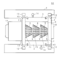
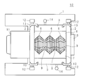
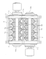
- FIG. 1 is a plan view of a main part showing a first example of the configuration of the crusher 50 of the present embodiment
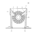
- FIG. 2 is a side view of a main part showing an example of the configuration of the crusher 50 of the present embodiment.
- the charging hopper is omitted.
- a pair of metal fixed side walls 2, 2 which are appropriately spaced apart from each other are provided on the upper surface of the support base 1.
- the pair of swinging side walls 3, 3 made of metal are arranged so as to be sandwiched between the fixed side walls 2, 2, and the fixed side walls 2, 2, and the swinging side walls 3, 3 constitute a housing.
- the housing of the crusher 50 has openings on the upper and lower sides.
- a bearing 10 is attached to a substantially central portion of one of the fixed side walls 2, and a reduction gear 11 to which an electric motor is attached is mounted to the other fixed side wall 2.
- a rotating shaft 25 interlocking with the motor shaft of the motor is suspended between the fixed side walls 2 and 2.
- crushing blades 6, 6 and 6 serving as rotary blades fitted on the rotating shaft 25 are accommodated.
- a cylindrical spacer 9 is fixed between the crushing blades 6 provided at an appropriate distance. Details of the crushing blade 6 will be described later.
- a fulcrum shaft 21 is suspended substantially vertically below the rotation shaft 25 and on a surface adjacent to the fixed side wall 2 of the swinging side wall 3 in parallel with the axial direction of the rotation shaft 25.
- the swing side walls 3, 3 are swingable around the fulcrum shaft 21, and opening the swing side walls 3, 3 opens the inside of the housing upward.
- the inside of one swinging side wall 3 is used for pulverizing the object to be pulverized (for example, a defective molded article or an excess molded article, but may include a sprue runner) in cooperation with each of the pulverizing blades 6.
- pulverizing the object to be pulverized for example, a defective molded article or an excess molded article, but may include a sprue runner
- a fall prevention plate 8 for preventing the object to be ground from falling down is bolted (not shown) so as to be inclined downward toward the inside. It is fixed inside the swinging side wall 3.
- lock members 13, each having a tapered surface are attached to fix the swing side walls 3, 3 to the fixed side walls 2, 2.
- the end portions of the fixed side wall 2 and the oscillating side wall 3 are sandwiched by one surface of the tapered shape, and the lever 12 screwed to the lock member 13 is tightened. Fix to 2.
- Each swing side wall 3 can be opened and closed by holding a handle 14 fixed to the swing side wall 3.
- the swing side walls 3 are fixed to the fixed side walls 2 by tightening the lever 12.
- the rotating shaft 25 rotates at a predetermined number of revolutions, and the crushing blade 6 rotates.
- the rotation direction is a direction in which the crushing blade 6 meshes with the fixed blade 7 from the upper side to the lower side.
- the object to be crushed is crushed into crushed material of a predetermined size by the cooperation of the crushing blade 6 and the fixed blade 7, and is sent to the lower side of the housing with the rotation of the crushing blade 6. Is discharged to the department.
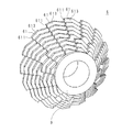
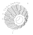
- FIG. 3 is an external perspective view showing a first example of the configuration of the crushing blade 6 of the present embodiment
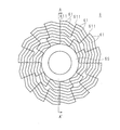
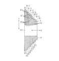
- FIG. 4 is a front view showing a first example of the configuration of the crushing blade 6 of the present embodiment
- FIG. 5 is a vertical sectional view of a main part taken along the line AA 'in FIG.
- the crushing blade 6 includes a plurality of blade unit groups 60 arranged so as to be adjacent to each other along the rotation axis direction (the direction indicated by the symbol X in the figure).
- the number of the blade portion groups 60 is eight, but is not limited to eight.
- Each of the plurality of blade groups 60 includes a plurality of blades 61 formed around the rotation axis on the outer periphery of the cylindrical body 62 fitted on the rotation shaft 25.
- the plurality of blades 61 are also referred to as blade rows.
- the blade portion 61 has a blade edge 611 formed at a tip portion around the rotation axis (see FIG. 3 or FIG. 4). That is, since the plurality of blade portions 60, that is, the plurality of blade portions 61 (blade rows) are arranged so as to be adjacent to each other along the rotation axis direction, there is no groove between the blade rows. (See FIG. 5).
- the second blade unit group 60 from the leftmost side from the center of the rotation axis of the blade unit 61 of the leftmost blade unit group 60 in the radial direction (the direction indicated by the symbol Y in the drawing).
- the dimension of the blade 61 in the radial direction from the center of the rotation axis is reduced by the height of the blade 61 (dimension in the Y direction).
- the center of the rotation axis of the blade 61 of the third blade group 60 from the left is larger than the radial dimension from the center of the rotation axis of the blade 61 of the second blade group 60 from the leftmost.
- the dimension in the radial direction is smaller by the height dimension of the blade 61.
- the eighth blade group from the left that is, the rightmost than the radial dimension from the center of the rotation axis of the blade 61 of the seventh blade group 60 from the leftmost.
- the radial dimension from the center of the rotation axis of the blade section 61 of the 60 is reduced by the height dimension of the blade section 61.
- the radial dimension from the center of the rotation axis of the spacer 9 is smaller by the height of the blade 61 of the eighth blade group 60 from the leftmost (that is, the rightmost).
- the radial dimension of the plurality of blades 61 from the center of the rotation axis is reduced stepwise for each of the plurality of blade groups 60 along the rotation axis direction.
- the dimension of the blade row in the radial direction from the center of the rotation axis gradually decreases along the direction from one end side to the other end side in the rotation axis direction.
- the radial dimension from the center of the rotation axis of the blade row gradually increases along the direction from the other end to the one end in the rotation axis direction.
- one side end 612 of the blade 61 of the second blade group 60 from the leftmost comes into contact with the cylindrical body 62 of the leftmost blade group 60. ing. Further, the other side end portion 613 of the blade portion 61 of the second blade portion group 60 from the leftmost side is located radially from the center of the rotation axis of the blade portion 61 of the third blade portion group 60 from the leftmost side. As a result of the size being reduced by the height of the blade portion 61, the blade is exposed.
- the exposure of the side end portion 613 means that the surface of the side end portion 613 is not in contact with anywhere and is not closed.
- one side end 612 of the blade 61 of the third blade group 60 from the leftmost comes into contact with the cylindrical body 62 of the second blade group 60 from the left, and 3 from the left.
- the other side end portion 613 of the blade portion 61 of the second blade portion group 60 is exposed.
- one side end 612 of the blade portion 61 of the eighth blade portion group 60 from the leftmost comes into contact with the cylindrical body 62 of the seventh blade portion group 60 from the leftmost.
- the other side end 613 of the blade 61 of the eighth blade group 60 from the left is exposed.
- one side end 612 in the rotation axis direction of the plurality of blades 61 of one blade group 60 is connected to the other edge adjacent to the one blade group 60. It comes into contact with the cylindrical body 62 of the blade group.
- the other side end portion 613 of the plurality of blade portions 61 of the one blade portion group 60 in the rotation axis direction is exposed. That is, one side end 612 of the blade row contacts the cylindrical body 62 on which the adjacent blade row is formed, and the other side end 613 of the blade row (that is, the radial dimension of the blade row is the rotation axis).
- the side end portion on the smaller side is exposed gradually in the direction.
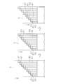
- FIG. 6 is a schematic diagram showing an example of a state in which the object S is caught between the crushing blade 6 and the fixed blade 7 of the present embodiment
- FIG. It is a schematic diagram which shows an example of a mode that the pulverized material S is pulverized.
- FIGS. 6 and 7 show a state in which a plate-like material S is ground for convenience.
- FIG. 6 shows that an object S to be ground supplied from a charging hopper (not shown) moves toward the fixed blade 7 with the rotation of the grinding blade 6, and is crushed by the cooperation of the grinding blade 6 and the fixed blade 7. Indicates a state that is about to be performed.
- FIG. 7 shows a case where it is viewed toward the fixed blade 7 in FIG.
- the cutting edge 611 of each of the plurality of blade portions 61 (blade row) of each blade portion group 60 crushes the material S to be crushed.
- one side end of each blade 61 is exposed (opened). Can be moved (dropped) in the direction of the arrow along the arrow, and as a result, the object to be crushed S falls downward toward the crushing blade 6, as shown in the center diagram of FIG. 7.
- each blade portion 61 is exposed.
- the object S can move (fall) in the direction of the arrow along the side end of the blade portion 61, and as a result, the object S falls downward toward the crushing blade 6, as shown in the right-hand diagram in FIG. Finally, it is pulverized to a predetermined size (particle size), and falls below the pulverizer 50.
- each blade portion 61 (blade row) decreases stepwise in the rotation axis direction, the object to be crushed easily moves toward the blade portion 61, By moving the object to be crushed, the object to be crushed can be further crushed.
- the blade portion group 60 is provided instead of the cylindrical groove between the blade rows, it is possible to prevent a part of the object to be ground from being stopped in the groove, and to improve the pulverization processing ability. Can be. In addition, it is possible to prevent the object to be ground from being retained and rubbed to generate powder, thereby making the particle size of the object to be ground uniform.
- each blade 61 (blade row) is exposed, the object to be crushed can move (fall) along the side end of each blade 61, and the crushing blade
- the crushed material crushed by the cooperation of the fixed blade 6 and the fixed blade 7 can be freely dropped away from each blade portion 61 (blade row) and collected in a predetermined collection box or the like.
- a plate-shaped scraper for scraping the crushed material crushed to a predetermined size (granular shape) by the crushing blade and discharging the crushed material to the material receiving portion on the lower side of the housing is provided.
- a scraper may be omitted in the present embodiment.
- FIG. 8 is a plan view of a main part showing an example of the configuration of a crusher 100 as a comparative example.
- a crusher 100 as a comparative example has a large rotating blade fitted on a rotating shaft in a space (crushing chamber) surrounded by fixed side walls 2 and 2 and swinging side walls 3 and 3.
- Crushing blades 104, 104 and crushing blades 106, 106, 106 as small rotating blades are accommodated.
- the coarse crushing blades 104, 104 protrude in an arc shape from the peripheral surface of the rotating shaft.
- the coarse crushing blades 104, 104 have an arm shape with a tip end (blade tip) curved in the rotation direction, and are disposed at an appropriate distance in the axial direction of the rotation shaft.
- the crushing blades 106, 106, 106 are disposed between the fixed side wall 2 and the coarse crushing blade 104, and between the coarse crushing blades 104, 104, and are formed with annular grooves at predetermined intervals in the rotation axis direction and are adjacent to each other.
- the outer peripheral surface of the annular projection between the annular grooves is formed in a sawtooth shape.
- first fixed blades 107a Inside the one swinging side wall 3, rectangular plate-shaped first fixed blades 107a,..., And second fixed blades for crushing the sprue runner in cooperation with each of the coarse crushing blades 104 and each of the crushing blades 106.
- the fixed blade 107 constituted by 107b is fixed so as to be inclined downward toward the inside.
- the first fixed blade 107a has substantially the same length in the longitudinal direction as the size in the axial direction of the crushing blade 106, and one edge on the long side is formed in an uneven shape so as to mesh with the cutting edge of the crushing blade 106. And is fixed to the inside of the swinging side wall 3 with bolts (not shown). Further, a tooth portion for crushing the sprue runner in cooperation with the coarse crushing blade 104 is formed on an edge portion on the short side of the first fixed blade 107a and close to the coarse crushing blade 104.
- the length of the second fixed blade 107b in the longitudinal direction is substantially the same as the dimension in the axial direction of the oscillating side wall 3, and at one edge on the long side and in the vicinity of the coarse crushing blade 104, A tooth portion for crushing the sprue runner is formed in cooperation with the coarse crushing blade 104.
- the second fixed blade 107b is fixed to the inside of the oscillating side wall 3 by a bolt (not shown) so as to contact the other edge of the first fixed blade 107a,.
- the inside of the other swinging side wall 3 is used to scrape the crushed material crushed to a predetermined size (grain shape) by the crushing blade 106 and discharge the crushed material to a material receiving portion (not shown) on the lower side of the housing. Is fixed by a bolt (not shown) so as to incline downward toward the inside.
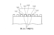
- FIG. 9 is a schematic diagram illustrating an example of a state in which the object S is caught between the crushing blade 106 and the fixed blade 107 as a comparative example
- FIG. 10 is a diagram illustrating the object to be crushed by the crushing blade 106 as a comparative example. It is a schematic diagram which shows an example of a mode that S is crushed. Actually, there are various shapes such as sprue runners and defective molded products, but FIGS. 9 and 10 show a state in which a plate-like material S is ground for convenience.
- FIG. 9 shows that the crushed object S input from an input hopper (not shown) moves toward the fixed blade 107 with the rotation of the crushing blade 106, and is crushed by the cooperation of the crushing blade 106 and the fixed blade 107. Indicates a state that is about to be performed.
- FIG. 10 shows a case when viewed toward the fixed blade 107 in FIG.
- a pulverizing blade 106 as a comparative example, a plurality of blade portions 161 (blade rows) are formed on the outer periphery of a cylindrical body at an appropriate distance. That is, the groove 162 exists between the adjacent blade rows.
- FIG. 10 when the material to be crushed S is supplied, a portion of the material to be crushed that hits the blade portion 161 is crushed by the crushing blade 106, whereas a portion of the material to be crushed S that crushes the groove 162 is crushed. Instead, there is a possibility that a part of the crushed object S fits between the grooves 162 and stops.
- each blade portion 61 (blade row) gradually decreases in the rotation axis direction. This facilitates the movement of the object to be crushed, and the object to be crushed moves, whereby the object to be crushed can be further crushed.
- there is no groove between the blade rows it is possible to prevent a part of the object to be ground from remaining in the groove. Thereby, it is possible to prevent the material to be crushed from being retained and rubbed to generate powder, and to make the particle size of the crushed material uniform.
- a blade surface can be formed at the other side end 613 of the plurality of blades 61. That is, as shown in FIG. 5, a blade surface can be formed at the exposed side end 613 of the blade row. This allows the object to be crushed to be crushed even with the blade surface of the side end portion 613, so that the crushing ability is increased.
- a plurality (three in the example of FIG. 1) of crushing blades 6 are arranged at an appropriate distance along the rotation axis direction. As a result, the processing amount of the object to be ground can be increased.
- the fixed blade 7 has a fixed blade surface 71 that engages with the crushing blade 6, and the fixed blade surface 71 has a plurality of blade portions 61 (each of the plurality of blade portion groups 60). It is formed stepwise corresponding to the tip of the blade row.
- the crushing blade 6 and the fixed blade 7 cooperate to crush the object to be crushed, the object to be crushed can be stopped and rubbed to prevent generation of powder, and the particle size of the crushed object can be made uniform. Can be.
- FIG. 11 is an external perspective view showing a second example of the configuration of the crushing blade 6 of the present embodiment
- FIG. 12 is a longitudinal sectional view of a main part showing a second example of the configuration of the crushing blade 6 of the present embodiment. is there.
- the difference from the first example illustrated in FIGS. 3 to 5 is that a plurality of blade portions 91 (blade rows) are provided on the outer periphery of the cylindrical spacer 9.
- the shape of the blade portion 91 may be the same shape as the blade portion 61, or may be a different shape.
- the dimension of the blade portion 91 of the spacer 9 in the radial direction from the center of the rotation axis is the height of the blade portion 61 of the eighth blade group 60 from the leftmost (that is, the rightmost). It is smaller by the dimensions.
- FIG. 13 is a schematic diagram showing an example of a state in which the crushed object S is crushed by the crushing blade 6 of the present embodiment.
- FIG. 13 shows a state in which the plate-like material S to be crushed is crushed for convenience.
- the blade portions 911 of the spacers 9 and the blade tips 611 of the plurality of blade portions 61 (blade rows) of each blade portion group 60 pulverize the material S to be ground.
- the lower portion of the crushed object S is crushed by the crushing blade 6, one side end of each blade 61 is exposed (opened). Can be moved (dropped) in the direction of the arrow along the arrow, and as a result, the object to be crushed S falls downward toward the crushing blade 6, as shown in the center diagram of FIG. 13.
- each blade portion 61 is exposed. It is possible to move (fall) in the direction of the arrow along the side end of the blade portion 61, and as a result, the crushed object S falls downward toward the crushing blade 6, and as shown in the right side diagram of FIG. Finally, it is pulverized to a predetermined size (particle size), and falls below the pulverizer 50.
- each blade portion 61 (blade row) decreases stepwise in the rotation axis direction, the object to be crushed easily moves toward the blade portion 61, By moving the object to be crushed, the object to be crushed can be further crushed. Further, since there is no groove between the blade rows, it is possible to prevent a part of the material to be crushed from stagnating in the groove, and to improve the pulverization processing ability. In addition, it is possible to prevent the object to be ground from being retained and rubbed to generate powder, thereby making the particle size of the object to be ground uniform.
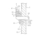
- FIG. 14 is a schematic view showing an example of the configuration of the inner side wall 22 of the fixed side wall 2 of the present embodiment
- FIG. 15 is a longitudinal sectional view showing a main part of the fixed side wall 2 of the present embodiment
- FIG. 14 shows the rotating shaft 25, the spacer 9 of the crushing blade 6, the fixed blade 7, and the fall prevention plate 8 for clarifying the positional relationship
- FIG. 14 shows the fixed side wall 2 as viewed from the crushing blade 6 side, and shows the inner side wall 22 of the fixed side wall 2.
- the inner wall 22 of the fixed side wall 2 is provided with a groove 23 that forms a part of an arc. That is, the groove 23 can have a shape that forms a part of an arc shape.
- FIG. 14 shows the rotating shaft 25, the spacer 9 of the crushing blade 6, the fixed blade 7, and the fall prevention plate 8 for clarifying the positional relationship
- FIG. 14 shows the fixed side wall 2 as viewed from the crushing blade 6 side, and shows the inner side wall 22 of the fixed side wall 2.
- the groove 23 has a semicircular shape, and includes a line segment from the center of the rotating shaft 25 to one end of the groove 23 and a line segment from the center of the rotating shaft 25 to the other end of the groove 23. Is 180 degrees at the center of the rotation axis 25 at which the two intersect, but is not limited to this, and the angle formed is, for example, 190 degrees, 200 degrees, 210 degrees, and the like. It may be.
- the inner wall 22 is an opposing wall of the housing that opposes the end of the crushing blade 6 that has the smallest radial dimension from the center of the rotating shaft 25.
- the term “end” refers to a case where the cylindrical spacer 9 is arranged between the blade group 60 having the smallest radial dimension and the fixed side wall 2 (housing) as shown in FIG. Can be a spacer 9.
- the blade 91 is provided on the outer periphery of the spacer 9, but the blade 91 may not be provided.
- the semicircular groove 23 is provided along the outer periphery of the end of the crushing blade 6, that is, along the movement trajectory along which the blade 91 moves as the crushing blade 6 rotates. As shown in FIG. 15, the groove 23 is surrounded by a bottom surface 230, an inner surface 231 bent from the bottom surface 230 in the direction of the rotation axis 25, and an outer surface 232. The inner side surface 231 is closer to the rotation shaft 25 than the outer side surface 232 is. That is, the outer surface 232 is a lower surface of the groove 23.
- the groove 23 is provided in the outer peripheral portion 911 of the blade portion 91 so as to be located between the inner side surface 231 and the outer side surface 232. That is, a space (gap) is formed between the blade portion 91 and the inner side wall 22 of the fixed side wall 2 by the groove 23.
- the semicircular arc-shaped groove 23 is provided along the outer periphery (the blade portion 91) of the end portion (spacer 9), the pulverized pulverized by the end portion and the inner wall 22 (opposing wall) is provided. Even if the object is caught, the crushed material can easily move through the space formed by the groove 23, and thus the crushed material can be removed.
- the outer side surface 232 is inclined so that the width of the groove 23 increases from the bottom surface 230 toward the opening of the groove 23. As a result, the crushed material that has entered the groove 23 slides downward on the outer side surface 232 and moves more easily, so that the crushed material can be more effectively removed.
- the end portion can be a blade portion group having the smallest radial dimension among the plurality of blade portion groups 60 of the crushing blade 6.
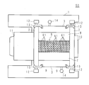
- FIG. 16 is a plan view of a principal part showing a second example of the configuration of the crusher 50 of the present embodiment.
- the crushing blade 6 has a configuration in which the diameter from the center of the rotating shaft to the blade portion 61 gradually decreases from one side to the other side in the rotating shaft direction.
- the diameter from the center of the rotating shaft to the blade portion 61 may gradually decrease from the center of the crushing blade 6 toward both ends in the rotating shaft direction.
- the diameter from the center of the rotating shaft to the blade portion 61 increases stepwise from both ends in the direction of the rotating shaft of the crushing blade 6 toward the center.
- each blade portion 61 (blade row) gradually decreases in the direction of the rotation axis, the object to be crushed easily moves toward the blade portion 61. By moving the object to be crushed, the object to be crushed can be further crushed.
- the blade portion group 60 is provided instead of the cylindrical groove between the blade rows, it is possible to prevent a part of the object to be ground from being stopped in the groove, and to improve the pulverization processing ability. Can be. In addition, it is possible to prevent the object to be ground from being retained and rubbed to generate powder, thereby making the particle size of the object to be ground uniform.
- FIG. 17 is a schematic view showing another example of the shape of the blade 61 of the crushing blade 6.
- each of the plurality of blades 61 has not only a blade 611 provided at a front end portion around a rotation axis (in a direction indicated by a symbol B in the drawing) but also a blade edge 615 at a rear end portion. Can be.
- the cutting edge 615 is formed not only at the front end portion but also at the rear end portion of the blade row. be able to.
- the fixed blade 7 may be attached instead of the fall prevention plate 8.
- FIG. 18 is a plan view of a principal part showing a third example of the configuration of the crusher 50 of the present embodiment.
- the difference from the above-described first example is that a coarse crushing blade 4 is provided between adjacent crushing blades 6.
- the coarse crushing blade 4 (referred to as a large rotary blade) has an arm shape with a distal end curved about a rotation axis.
- the crusher 50 includes two coarse crushing blades 4. By providing the coarse crushing blade 4, a sprue runner having a large shape can be crushed. Since the coarse crushing blade 4 is not essential, it may not be provided.
- the coarse crushing blade 4 may be attached, if necessary, according to the type of the object to be crushed. However, when the coarse crushing blade 4 is attached, it is necessary to limit the amount of the material to be crushed to be charged into the crushing chamber so as not to exceed a predetermined amount.
- FIG. 19 is a plan view of a principal part showing a fourth example of the configuration of the crusher 50 of the present embodiment.
- the difference from the above-described second example is that the coarse crushing blade 4 is provided between the adjacent crushing blades 6 as in the third example.
- the coarse crushing blade 4 has an arm shape with a tip portion around the rotation axis curved.
- the crusher 50 includes two coarse crushing blades 4. By providing the coarse crushing blade 4, a sprue runner having a large shape can be crushed.
- the coarse crushing blade 4 is not essential. If necessary, depending on the type of the object to be crushed, the amount of the object to be crushed into the crushing chamber may be limited, and then the coarse crushing blade 4 may be attached.
- the object to be crushed does not stay on the crushing blade, for example, in a groove, so that the object to be crushed rubs on the surface of the groove or the like to generate powder. Can be prevented, and the particle size of the pulverized material can be made uniform.
- one side end of the blade portion can be exposed, and by forming a blade surface on the side end portion, the object to be ground can be crushed not only at the tip end portion of the blade portion but also at the side end portion. Therefore, the crushing ability can be increased. Further, as exemplified in FIGS. 1 and 16, the combination of the blade rows can be changed, so that the crushed object in various modes such as the type and shape of the crushed object (for example, a block such as a defective molded product). Mass) can be ground.
- the crusher 50 does not need to crush the crushed object that is stagnated by the crushing blade (large rotary blade) unlike the conventional crusher because the crushed object does not stay. As a result, no crushing blade is required. This eliminates the need for a large cutting torque required for coarse crushing by the large rotating blade having a large shape, and allows the crusher to be downsized. Also, it is not necessary to provide a semi-circular cover below the rotating shaft so that a relatively large crushed material having a shape crushed by the large rotary blade is not collected. As a result, the crusher can be reduced in weight and size. And cost can be reduced.
- the capacity of the motor can be reduced to about 1/3 of the capacity of the motor in the case of a pulverizer having a large rotating blade, and the reduction gear torque is sufficient, and the strength is reduced. It becomes unnecessary.
- power consumption can be reduced.
- the crushing blade 6 can be rotated in the reverse direction to crush the object to be crushed. 6 can be extended. In addition, by repeating the normal rotation and the reverse rotation of the crushing blade 6 at an appropriate time interval or frequency, it is possible to further prevent the object to be crushed from remaining.
- the large rotating blade has a larger shape than the crushing blade and takes in a large amount of crushed material at a time. Cannot be stored. For this reason, it is necessary to provide an interval when charging the crushed material from the charging hopper to limit the amount of the crushed material to be supplied to a certain amount or more. Since the object does not stay and does not have the large rotary blade, there is no need to provide such an interval, and the processing time can be reduced.
- the number of rotations of the crushing blade 6 can be increased (for example, a rotation speed of about 25 to 30 rpm in the related art is further increased) according to the input amount of the crushed object.
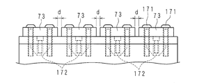
- FIGS. 20A, 20B, and 20C are explanatory views showing an example of a main part near the fixed blade 7.
- FIG. FIG. 20A is a plan view showing an engagement state between the fixed blade 7 and the crushing blade 6, and FIG. 20B is a plan view in which the crushing blade 6 is omitted for easy understanding of the structure of the fixed blade 7.
- 20C is a front view as seen from the direction indicated by reference numeral C in FIG. 20B.
- Reference numeral 72 denotes a fixing plate.
- the fixed plate 72 is a plate that is long along the rotation axis direction (the direction indicated by the symbol X in the drawing), and is fixed to the housing by bolts 172.
- the fixed blade 7 has a fixed plate 72 and a plurality of small fixed blades 73.
- the small fixed blade 73 has a fixed blade surface that engages with the crushing blade 6, and the fixed blade surface is formed by a plurality of blade portions 61 (blade row) of each of the plurality of blade portion groups 60. It is formed stepwise corresponding to the tip.
- the small fixed blades 73 are fixed to the fixed plate 72 by bolts 171 at an appropriate distance from each other (indicated by d).
- the small fixed blade 73 is attached so as to be able to move minutely along the rotation axis direction, and can be fixed by the bolt 171 after finely adjusting the position. Since the small fixed blades 73 are fixed to the fixed plate 72 at an appropriate distance in the direction of the rotation axis, it is possible to adjust the distance between adjacent small fixed blades 73 and fix the small fixed blades 73 to the fixed plate 72.
- the fixed position of the small fixed blade 73 is fixed. Can be adjusted, so that the crushing blade 6 and the small fixed blade 73 can be appropriately engaged.
- a spacer for dimension adjustment may be mounted between the small fixed blades 73.
- a member for dimension adjustment such as a skimmer gauge, may be mounted at a desired position in a blade group adjacent to the crushing blade 6.
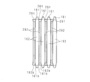
- FIG. 21 is a side view showing an example of a main part of the crushing blade 6 of the second embodiment.
- FIG. 22 is a side view showing an example of a main part near the crushing blade 6 of the crusher of the second embodiment.
- the radial dimension of the plurality of blades from the center of the rotation axis differs between adjacent blade groups. Since the radial dimension of each blade portion (blade row) is different in the adjacent blade portion group, the object to be crushed is easily moved toward the blade portion, and the object to be crushed is moved by the movement of the object to be crushed. The object can be further crushed. Thereby, it is possible to prevent the material to be crushed from being retained and rubbed to generate powder, and to make the particle size of the crushed material uniform.
- a specific description will be given.
- the first blade group includes a plurality of blades 161 formed around the rotation axis on the outer periphery of the cylindrical body 162 fitted on the rotation shaft 25.
- the blade portion 161 has a blade edge formed at a tip portion around the rotation axis.
- the second blade group includes a plurality of blades 261 formed around the rotation axis on the outer periphery of the cylindrical body 262 fitted on the rotation shaft 25.
- the blade portion 261 has a blade edge formed at a tip portion around the rotation axis.
- the radial dimension of the plurality of blades 161 of the first blade group from the center of the rotation axis is larger than the radial dimension of the plurality of blades 261 of the second blade group from the center of the rotation axis.
- first blade portion group and the second blade portion group are arranged adjacently (closely) along the rotation axis direction, there is no groove between the blade rows. It has become.
- each of the plurality of blade portions 261 of the second blade portion group around the rotation shaft 25 decreases in the radial direction from the center of the rotation shaft 25.
- the front end side or the rear end side of the blade portion 261 formed on the outer periphery 262a of the cylindrical body of the second blade portion group, the center of the rotating shaft 25 and the front end portion or the rear end portion 261a of the blade portion 261. Is 0 ° or more.
- the angle ⁇ formed with the surface connecting the end 161a may be 0 ° or more.
- FIGS. 23 and 24 are schematic diagrams showing an example of a state in which the material to be ground is discharged.
- the dimension of each of the plurality of blade portions 261 of the second blade portion group around the rotation axis decreases in the radial direction from the center of the rotation shaft.
- the first blade unit group has a large radial dimension from the center of the rotation axis of the plurality of blade units 161, and the second blade unit group has the rotation shaft of the plurality of blade units 261. Is smaller in the radial direction from the center than in the case of the first blade group.
- the cylinders 162 of each of the two first blade groups adjacent to the second blade group are arranged facing each other with a gap between adjacent blades 261 of the second blade group.
- the dimension (width dimension) of the cylindrical body 162 in the rotation axis direction decreases in the radial direction from the center of the rotation axis.
- the cylindrical body 162 has a tapered surface 162b so that the width of the cylindrical body 162 decreases in the radial direction.
- an elastic reaction force can be applied from the cylindrical body 162 to the object to be crushed (indicated by S), and the object to be crushed is discharged from the gap.
- the dimension (width dimension) in the rotation axis direction of the plurality of blade portions 161 of the first blade portion group can be reduced in the radial direction from the center of the rotation shaft.
- the tapered surface 162b of the cylindrical body 162 and the tapered surface 161b of the blade portion 161 may be coplanar. This makes it easier to discharge the material to be ground.
- FIG. 25 is a plan view of a main part showing another example of the configuration of the crusher 50 of the second embodiment
- FIG. 26 is a side view of a main part showing another first example of the configuration of the crusher 50 of the second embodiment.
- the plurality of blades 61 have cutting edges formed at the tips around the rotation axis 25, and the dimensions of the plurality of blades 61 in the radial direction from the center of the rotation shaft 25 are the same as those of the adjacent blades.
- the blade group can be shared, the cutting edge of the fixed blade 7 can be made straight, and the shape of the fixed blade 7 can be simplified.
- two second blade portions adjacent to the second blade portion group with a gap Ga between the adjacent blade portions 61a of the second blade portion group (for example, the blade portion group in the front in FIG. 26).
- the blades 61b of one blade group are arranged to face each other.
- the gap Ga between the adjacent blade portions 61a of the second blade portion group and the gap Gb between the adjacent blade portions 61b of the first blade portion group do not overlap along the rotation axis 25 direction. It is possible to prevent the material to be crushed from staying and rubbing to generate powder, and to make the particle size of the crushed material uniform.
- FIG. 27 is a side view of a main part showing another second example of the configuration of the crusher 50 of the second embodiment.
- the difference from FIG. 26 is that the fixed blade 7 and the fall prevention plate 8 are arranged so as to be substantially flush with each other. That is, the angle between the upper surface of the fixed blade 7 and the upper surface of the fall prevention plate 8 may be approximately 180 ° as shown in FIG. 27, approximately 90 ° as shown in FIG. Can be set to an appropriate angle in the range of approximately 90 ° to approximately 180 ° according to the above.
- the crusher when the crusher is not provided with the coarse crushing blade 4, the object to be crushed is pushed toward the crushing blade by the pushing device, thereby improving the processing capacity (for example, crushing amount, crushing time). Can be done.
- the pushing device a specific example of the pushing device will be described.
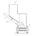
- FIG. 28 is a side view showing an example of the obliquely pushing type pushing device 120.
- the crushing blade is shown so as to be seen.
- the push-in portion performs a diagonal forward and backward motion with a predetermined stroke by the guide air cylinder 121, thereby crushing the material to be crushed. It can be pushed towards the blade.
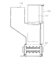
- FIG. 29 is a side view showing an example of a vertical pressing type pressing device 130.
- the crushing blade is shown so as to be seen.
- the pushing section 131 moves up and down with a predetermined stroke by an air cylinder with a guide, thereby moving the crushed material into the crushing blade. Can be pushed towards
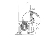
- FIGS. 30A and 30B are explanatory views showing an example of the rotary pushing type pushing device 140.
- FIG. 30 shows a configuration viewed from the front
- FIG. 30B shows a configuration viewed from the side.
- the crushing blade is shown so as to be visible.
- the driving unit 141 drives the rotary pushing unit 142 to rotate, thereby causing the crushed material to move toward the crushing blade. Can be pushed into.
- a single-shaft crusher was described, but the crusher is not limited to a single-shaft crusher, and may be a multi-shaft crusher.
- a two-shaft crusher will be described.
- FIG. 31 is a plan view of a main part showing a first example of a configuration of a two-shaft crusher
- FIG. 32 is a side view of a main part showing a first example of a configuration of a two-shaft crusher.
- One fixed side wall 2 is provided with a bearing 10a
- the other fixed side wall 2 is provided with a speed reducer 11a having an electric motor mounted thereon.
- a bearing 10b is attached to the other fixed side wall 2
- a reduction gear 11b to which an electric motor is attached is attached to one fixed side wall 2, and the electric motor is connected via the reduction gear 11b.
- a rotating shaft 25b interlocking with the motor shaft is suspended between the fixed side walls 2,2.
- a crushing blade 6a as a rotary blade fitted to the rotating shaft 25a is housed and fitted to the rotating shaft 25b.
- the grinding blade 6b as a rotating blade is accommodated.
- a fixed blade 7a engaging with the crushing blade 6a is fixed to one swinging side wall 3
- a fixed blade 7b engaging with the crushing blade 6b is fixed to the other swinging side wall 3.
- a plurality of blade portions whose radial dimension decreases from the center of the rotary shaft 25b are located at positions of the blade group including a plurality of blade portions whose radial size increases from the center of the rotary shaft 25a.
- the crushing blades 6a and 6b are attached so as to correspond to the positions of the blade unit group provided with. In other words, at the position of the blade group having a plurality of blade portions whose radial dimension increases from the center of the rotating shaft 25b, a plurality of blade portions whose radial size decreases from the center of the rotating shaft 25a.
- the crushing blades 6a and 6b are attached so as to correspond to the positions of the blade unit group provided with.
- the crushing capacity of the blade group having a large radial dimension is relatively large, and the crushing capacity of the blade group having a small radial dimension is relatively small. Can be equalized.
- the rotation shaft 25a can be rotated left and right (reference numerals A1 and A2 in the drawing), and the rotation shaft 25b can be rotated left and right (reference numerals B1 and B2 in the drawing).
- the rotating shaft 25a is rotated in the direction of the symbol A1
- the rotating shaft 25b is rotated in the direction of the symbol B2.
- the rotation direction can be changed in the following order. That is, the rotating shaft 25a is rotated in the direction of the symbol A1, and the rotating shaft 25b is rotated in the direction of the symbol B1.
- the rotating shaft 25a is rotated in the direction of the symbol A2, and the rotating shaft 25b is rotated in the direction of the symbol B2. Then, the rotating shaft 25a is rotated in the direction of the symbol A2, and the rotating shaft 25b is rotated in the direction of the symbol B1.
- FIG. 33 is a plan view of a main part showing a second example of a configuration of a two-shaft crusher
- FIG. 34 is a side view of a main part showing a second example of a configuration of a two-shaft crusher.
- the difference from the first example shown in FIGS. 31 and 32 is that a fixed blade 7c is provided. That is, the fixed blade 7c is provided between the crushing blade 6a and the crushing blade 6b.
- the fixed blade 7 can crush the object to be crushed by engaging with the crushing blades 6a and 6b.
- the other configuration is the same as that of the first example, and the description is omitted.
- the provision of the fixed blade 7c can improve the crushing ability.
- the crusher according to the present embodiment has a housing having an opening on the upper side, a rotary blade attached to a rotary shaft placed laterally in the housing, and disposed in the housing and engaged with the rotary blade.
- a crusher that includes a fixed blade and crushes an object to be crushed in cooperation with the rotary blade and the fixed blade, wherein the rotary blade has a plurality of blades arranged so as to be adjacent along the rotation axis direction.
- a plurality of blades formed around the rotation axis on the outer periphery of the cylindrical body fitted on the rotation shaft.
- the crusher includes a housing having an opening on an upper side, a rotating blade (also referred to as a crushing blade) mounted on a rotating shaft placed horizontally in the housing, and a fixed blade disposed in the housing and engaged with the rotating blade.
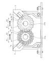
- the rotary blade includes a plurality of blade unit groups arranged so as to be adjacent to each other along the rotation axis direction.
- Each of the plurality of blade groups includes a plurality of blades formed around the rotation axis on the outer periphery of the cylindrical body fitted on the rotation shaft.
- the plurality of blades are also referred to as a blade row. That is, since a plurality of blade rows are arranged adjacent to each other along the rotation axis direction, no groove exists between the blade rows.
- the plurality of blades are formed with a blade edge at a tip end around the rotation axis, and the radial dimension of the plurality of blades from the center of the rotation axis is The size of each of the plurality of blade groups decreases stepwise along the rotation axis direction.
- the radial dimension of the plurality of blades from the center of the rotation axis decreases stepwise in the plurality of blade groups along the rotation axis direction. That is, the dimension of the blade row in the radial direction from the center of the rotation axis gradually decreases in the direction of the rotation axis.
- each blade portion (blade row) gradually decreases in the direction of the rotation axis, the material to be crushed easily moves toward the blade portion, and the material to be crushed moves. Thereby, the object to be ground can be further ground. Thereby, it is possible to prevent the material to be crushed from being retained and rubbed to generate powder, and to make the particle size of the crushed material uniform.
- one side end in the rotation axis direction of the plurality of blade portions of one blade portion group is formed into a cylindrical body of another blade portion group adjacent to the one blade portion group.
- the other side ends of the plurality of blade portions in the rotation axis direction are exposed.
- One side end in the rotation axis direction of the plurality of blade portions of one blade portion group comes into contact with the cylindrical body of another blade portion group adjacent to one blade portion group.
- the other side ends in the rotation axis direction of the plurality of blade portions of the one blade portion group are exposed. That is, one side end of the blade row abuts on the cylindrical body on which the adjacent blade row is formed, and the other side end of the blade row (that is, the radial dimension of the blade row faces the rotation axis direction). And the smaller side end) is exposed. Since the side edges of the blade row are exposed, the pulverized material pulverized by the cooperation of the rotary blade and the fixed blade can fall freely from the blade row and be collected in a predetermined collection box. can do.
- the crusher according to the present embodiment is configured such that the casing is opposed to the end of the rotary blade that is closer to the rotary shaft than the fixed blade and has a minimum radial dimension from the center of the rotary shaft.
- the opposing wall is provided with a groove that forms part of an arc along the outer periphery of the end.
- An outer wall of the end of the rotary blade at a location facing the end of the rotary blade having a minimum radial dimension from the center of the rotary shaft and at a position closer to the rotary shaft than the fixed blade; Are formed along the groove.
- the end of the rotary blade includes a blade group having the smallest radial dimension among a plurality of blade groups of the rotary blade, or a blade group having the smallest radial dimension and the housing. When a cylindrical spacer is arranged between the spacers, the spacer is included. Since a groove that forms a part of an arc is provided along the outer circumference of the end portion, even if the crushed material is sandwiched between the end portion and the opposing wall of the housing, it can be removed through the groove.
- a blade surface is formed at the other side end of the plurality of blades.
- a blade surface is formed on the other side end of the plurality of blade portions. That is, since the blade surface is formed at the exposed side end of the blade row, the pulverizing ability is increased.
- the plurality of blade portions have blade edges formed at rear ends around the rotation axis.
- the plurality of blades have blade edges formed at the rear end around the rotation axis.
- the rotary blade can be reversed and the life of the rotary blade can be extended.
- by reversing the rotary blade it is possible to further prevent the object to be ground from being retained.
- a plurality of the rotary blades are arranged at an appropriate distance from each other along the rotation axis direction.
- a plurality of rotary blades are arranged at an appropriate distance in the direction of the rotation axis. As a result, the processing amount of the object to be ground can be increased.
- the crusher according to the present embodiment includes a large rotary blade that is attached to a rotary shaft between the adjacent rotary blades and has an arm-like shape with a curved end around the rotary axis.
- a large rotary blade (also referred to as a coarse crushing blade) which is attached to a rotary shaft between adjacent rotary blades and has an arm shape with a curved end around the rotary axis.
- a sprue runner having a large shape can be crushed.
- the fixed blade has a fixed blade surface that engages with the rotary blade, and the fixed blade surface is provided at a tip end of a plurality of blades of each of the plurality of blade groups. It is formed stepwise correspondingly.
- the fixed blade has a fixed blade surface that engages with the rotary blade, and the fixed blade surface is formed stepwise in correspondence with the tips of the plurality of blades of each of the plurality of blade groups.
- the crusher of the present embodiment includes a fixed plate fixed to the housing along the rotation axis direction, the fixed blade has a fixed blade surface that engages with the rotary blade, and the fixed plate And a plurality of small fixed blades fixed at a suitable distance from each other.
- the small fixed blades are fixed to the fixed plate at an appropriate distance in the rotation axis direction, the distance between adjacent small fixed blades can be adjusted and fixed to the fixed plate. Adjusting the fixed position of the small fixed blade when multiple blade groups of rotary blades are arranged adjacent to each other along the rotation axis direction, even if dimensional errors in the rotation axis direction of each blade group are accumulated Therefore, the rotary blade and the fixed blade can be appropriately engaged.
- the plurality of blades have a cutting edge formed at a tip end around the rotation axis, and the radial dimension of the plurality of blades from the center of the rotation axis is: Different for adjacent blade groups.
- the radial dimension of the plurality of blades from the center of the rotation axis differs between adjacent blade groups. Since the radial dimension of each blade portion (blade row) is different in the adjacent blade portion group, the object to be crushed is easily moved toward the blade portion, and the object to be crushed is moved by the movement of the object to be crushed. The object can be further crushed. Thereby, it is possible to prevent the material to be crushed from being retained and rubbed to generate powder, and to make the particle size of the crushed material uniform.
- the crusher of the present embodiment has a first blade group having a large radial dimension from the center of the rotation axis of a plurality of blades, and a plurality of blades adjacent to the first blade group.
- a second blade section group having a small radial dimension from the center of the rotation shaft, and two adjacent blade sections adjacent to the second blade section group with a gap between adjacent blade sections of the second blade section group interposed therebetween.
- the cylinders of the first blade portion group are arranged to face each other, and the dimension of the cylinder in the direction of the rotation axis decreases in the radial direction from the center of the rotation axis.
- a first blade group having a large radial dimension from the center of the rotation axis of the plurality of blades, and a small radial dimension from the center of the rotation axis of the plurality of blades adjacent to the first blade group.
- a second blade group The cylinders of the two first blade groups adjacent to the second blade group are opposed to each other with a gap between adjacent blades in the second blade group.
- the dimension (width dimension) of the cylindrical body in the rotation axis direction decreases in the radial direction from the center of the rotation axis.
- the width of the cylindrical body is tapered so as to decrease in the radial direction.
- An elastic reaction force can be applied to the object to be crushed, and the object to be crushed is discharged from the gap. Thereby, it is possible to prevent the material to be crushed from being retained and rubbed to generate powder, and to make the particle size of the crushed material uniform.
- the dimension of each of the plurality of blade portions of the second blade portion group around the axis of the rotating shaft is reduced in a radial direction from the center of the rotating shaft.
- each of the plurality of blades of the second blade group around the rotation axis becomes smaller in the radial direction from the center of the rotation shaft.
- the plurality of blades have a cutting edge formed at a tip end around the rotation axis, and a radial dimension of the plurality of blades from the center of the rotation axis is: The same is true for adjacent blade groups.
- the plurality of blades have cutting edges formed at the tips around the rotation axis, and the dimensions of the plurality of blades in the radial direction from the center of the rotation axis are the same in adjacent blade groups. Thereby, the blade group can be shared, the blade edge of the fixed blade can be made straight, and the shape of the fixed blade can be simplified.
- the crusher according to the present embodiment is configured such that the blade portions of two other blade portion groups adjacent to the one blade portion group are opposed to each other with a gap between adjacent blade portions of one blade portion group interposed therebetween. is there.
- the blades of two other blade groups adjacent to the one blade group are opposed to each other with a gap between adjacent blades of the one blade group.
- the gap between the adjacent blades of one blade group and the gap between the adjacent blades of the other blade group do not overlap along the rotation axis direction, so that the object to be ground stays.
- the crusher according to the present embodiment includes a first rotary shaft and a second rotary shaft to which the rotary blade is attached and which is laterally placed in the housing, and has a large radial dimension from the center of the first rotary shaft. Attaching the rotary blade to the position of the blade group including a plurality of blade portions, the position of the blade portion group including a plurality of blade portions having a smaller radial dimension from the center of the second rotation axis. is there.
- a blade group including a plurality of blade portions having a plurality of blade portions having a radial dimension smaller than the center of the first rotation shaft and a plurality of blade portions having a plurality of blade portions having a radial size smaller than the center of the second rotation shaft.
- the rotary blade is attached to correspond to the position of.
- the crushing capacity of the blade group having a large radial dimension is relatively large, and the crushing capacity of the blade group having a small radial dimension is relatively small. Can be equalized.
Landscapes
- Engineering & Computer Science (AREA)
- Food Science & Technology (AREA)
- Crushing And Pulverization Processes (AREA)
- Separation, Recovery Or Treatment Of Waste Materials Containing Plastics (AREA)
- Processing And Handling Of Plastics And Other Materials For Molding In General (AREA)
Abstract
Description
以下、本発明をその実施の形態を示す図面に基づいて説明する。図1は本実施の形態の粉砕機50の構成の第1例を示す要部平面図であり、図2は本実施の形態の粉砕機50の構成の一例を示す要部側面図である。なお、図1及び図2では投入ホッパを省略している。図1及び図2に示すように、支持台1の上面には、適長離隔した1対の金属製の固定側壁2、2を対設してあり、固定側壁2、2の両側部には、1対の金属製の揺動側壁3、3が固定側壁2、2で挟まれるように配置してあり、固定側壁2、2、及び揺動側壁3、3により筐体を構成している。粉砕機50の筐体は、上側及び下側に開口部を有する。
前述の第1実施形態では、複数の刃部群60それぞれの複数の刃部61(刃列)の先端部が段階的に形成してある構成であったが、これに限定されない。以下、第2実施形態について説明する。
3 揺動側壁(筐体)
4 粗砕刃(大回転刃)
6、6a、6b 粉砕刃(回転刃)
7、7a、7b、7c 固定刃
8 落下防止板
9 スペーサ
22 内側壁
23 溝
25、25a、25b 回転軸
50 粉砕機
60 刃部群
61、61a、61b、91、161、261 刃部
62、162、262 円筒体
611、615 刃先
612、613 側端部
72 固定板
73 小固定刃
120、130、140 押し込み装置
161a、261a 先端部又は後端部
161b、162b テーパ面
162a、262a 外周
171、172 ボルト
Claims (16)
- 上側に開口部を有する筐体と、該筐体内で横置きされた回転軸に取り付けられた回転刃と、前記筐体内に配置され前記回転刃と係合する固定刃とを備え、前記回転刃と固定刃との協働により被粉砕物を粉砕する粉砕機であって、
前記回転刃は、
前記回転軸方向に沿って隣接するように並べた複数の刃部群を備え、
前記複数の刃部群それぞれは、
前記回転軸に嵌装された円筒体の外周に前記回転軸回りに沿って形成された複数の刃部を備える粉砕機。 - 前記複数の刃部は、
前記回転軸回りの先端部に刃先を形成してあり、
前記複数の刃部の前記回転軸の中心からの径方向の寸法が、前記回転軸方向に沿って前記複数の刃部群毎に段階的に小さくなる請求項1に記載の粉砕機。 - 一の刃部群の複数の刃部の前記回転軸方向の一方の側端部は、前記一の刃部群に隣接する他の刃部群の円筒体に当接し、
前記複数の刃部の前記回転軸方向の他方の側端部は、露出している請求項1又は請求項2に記載の粉砕機。 - 前記固定刃よりも前記回転軸側であって、前記回転軸の中心からの径方向の寸法が最小となる前記回転刃の端部に対向する前記筐体の対向壁に、前記端部の外周に沿って円弧の一部をなす溝を設けてある請求項1から請求項3のいずれか一項に記載の粉砕機。
- 前記複数の刃部の前記他方の側端部に刃面を形成してある請求項3に記載の粉砕機。
- 前記複数の刃部は、
前記回転軸回りの後端部に刃先を形成してある請求項1から請求項5のいずれか一項に記載の粉砕機。 - 前記回転刃を前記回転軸方向に沿って適長離隔して複数配置してある請求項1から請求項5のいずれか一項に記載の粉砕機。
- 隣り合う前記回転刃の間の回転軸に取り付けられ、前記回転軸回りの先端部が湾曲したアーム状をなす大回転刃を備える請求項7に記載の粉砕機。
- 前記固定刃は、
前記回転刃に係合する固定刃面を有し、
前記固定刃面は、
前記複数の刃部群それぞれの複数の刃部の先端部に対応して段階的に形成してある請求項1から請求項8のいずれか一項に記載の粉砕機。 - 前記回転軸方向に沿って前記筐体に固定された固定板を備え、
前記固定刃は、
前記回転刃に係合する固定刃面を有し、前記固定板に適長離隔して固定された複数の小固定刃を有する請求項1から請求項9のいずれか一項に記載の粉砕機。 - 前記複数の刃部は、
前記回転軸回りの先端部に刃先を形成してあり、
前記複数の刃部の前記回転軸の中心からの径方向の寸法は、隣接する刃部群で異なる請求項1に記載の粉砕機。 - 複数の刃部の前記回転軸の中心からの径方向の寸法が大きい第1刃部群と、
前記第1刃部群に隣接し、複数の刃部の前記回転軸の中心からの径方向の寸法が小さい第2刃部群と
を備え、
前記第2刃部群の隣り合う刃部の隙間を間にして前記第2刃部群に隣接する2つの前記第1刃部群それぞれの円筒体を対向配置してあり、
前記円筒体の前記回転軸方向の寸法は、前記回転軸の中心からの径方向に向かって小さくなるようにしてある請求項11に記載の粉砕機。 - 前記第2刃部群の複数の刃部それぞれの前記回転軸の軸回りの寸法は、前記回転軸の中心からの径方向に向かって小さくなるようにしてある請求項12に記載の粉砕機。
- 前記複数の刃部は、
前記回転軸回りの先端部に刃先を形成してあり、
前記複数の刃部の前記回転軸の中心からの径方向の寸法は、隣接する刃部群で同等である請求項1に記載の粉砕機。 - 一の刃部群の隣り合う刃部の隙間を間にして前記一の刃部群に隣接する2つの他の刃部群それぞれの刃部を対向配置してある請求項14に記載の粉砕機。
- 前記回転刃が取り付けられ、前記筐体内で横置きされた第1回転軸及び第2回転軸を備え、
前記第1回転軸の中心から径方向の寸法が大きくなる複数の刃部を備える刃部群の位置に、前記第2回転軸の中心から径方向の寸法が小さくなる複数の刃部を備える刃部群の位置を対応させて前記回転刃を取り付けてある請求項2に記載の粉砕機。
Priority Applications (3)
| Application Number | Priority Date | Filing Date | Title |
|---|---|---|---|
| CN201880095125.3A CN112399890A (zh) | 2018-07-17 | 2018-12-06 | 粉碎机 |
| JP2020530878A JP7162914B2 (ja) | 2018-07-17 | 2018-12-06 | 粉砕機 |
| EP18926448.4A EP3825007A4 (en) | 2018-07-17 | 2018-12-06 | MILL |
Applications Claiming Priority (2)
| Application Number | Priority Date | Filing Date | Title |
|---|---|---|---|
| JP2018-134510 | 2018-07-17 | ||
| JP2018134510 | 2018-07-17 |
Publications (1)
| Publication Number | Publication Date |
|---|---|
| WO2020017073A1 true WO2020017073A1 (ja) | 2020-01-23 |
Family
ID=69163499
Family Applications (1)
| Application Number | Title | Priority Date | Filing Date |
|---|---|---|---|
| PCT/JP2018/044983 Ceased WO2020017073A1 (ja) | 2018-07-17 | 2018-12-06 | 粉砕機 |
Country Status (4)
| Country | Link |
|---|---|
| EP (1) | EP3825007A4 (ja) |
| JP (1) | JP7162914B2 (ja) |
| CN (1) | CN112399890A (ja) |
| WO (1) | WO2020017073A1 (ja) |
Cited By (2)
| Publication number | Priority date | Publication date | Assignee | Title |
|---|---|---|---|---|
| CN116329558A (zh) * | 2023-03-31 | 2023-06-27 | 昆山佳俊智能科技有限公司 | 一种全自动镁屑断削及磨粉设备 |
| US20230278040A1 (en) * | 2022-03-02 | 2023-09-07 | Battelle Energy Alliance, Llc | Crusher/perforator for recylceable materials |
Citations (8)
| Publication number | Priority date | Publication date | Assignee | Title |
|---|---|---|---|---|
| JPS4740016B1 (ja) * | 1970-03-31 | 1972-10-09 | ||
| JPS5233653Y2 (ja) * | 1972-07-06 | 1977-08-01 | ||
| JPS5430907A (en) * | 1977-08-10 | 1979-03-07 | Kobayashi Seisakusho | Beater for waste paper |
| JPS6129484Y2 (ja) * | 1983-02-12 | 1986-08-30 | ||
| JPS62123248U (ja) * | 1986-01-30 | 1987-08-05 | ||
| JPH11188279A (ja) * | 1997-12-26 | 1999-07-13 | Furukawa Co Ltd | 破砕装置 |
| JPH11333313A (ja) * | 1998-05-25 | 1999-12-07 | Sumieito Kk | 横型一軸破砕機及び廃棄物の破砕方法 |
| JP2010042384A (ja) | 2008-08-18 | 2010-02-25 | Matsui Mfg Co | 粉砕機 |
Family Cites Families (14)
| Publication number | Priority date | Publication date | Assignee | Title |
|---|---|---|---|---|
| US5052630A (en) * | 1990-02-27 | 1991-10-01 | Mac Corporation | Method and apparatus to reduce material |
| DE19700808A1 (de) * | 1997-01-13 | 1998-07-16 | Lindemann Maschfab Gmbh | Rotorschere zum Zerkleinern von insbesondere sperrigen Abfällen mit einem Schneidrotor und einem feststehenden Gegenmesser |
| CN2342889Y (zh) * | 1998-10-15 | 1999-10-13 | 王桂贞 | 粉碎机 |
| DE20001891U1 (de) * | 2000-02-03 | 2000-05-04 | Habermehl, Lothar, 35510 Butzbach | Schneidwerk |
| US20020047062A1 (en) * | 2000-06-12 | 2002-04-25 | Keskula Robert J. | Granulator |
| DK176582B1 (da) * | 2005-06-22 | 2008-10-06 | M & J Ind As | Findelingsmaskine |
| CN201572677U (zh) * | 2009-11-18 | 2010-09-08 | 上海申嘉三和环保科技开发有限公司 | 生活垃圾分选系统 |
| CN101722092A (zh) * | 2009-12-03 | 2010-06-09 | 黄国宏 | 一种塑料破碎机的破碎机构 |
| CN102091667A (zh) * | 2009-12-12 | 2011-06-15 | 浙江兴德电子有限公司 | 粉碎塑料的组合刀具以及粉碎塑料的慢速粉碎机 |
| CN201701991U (zh) * | 2010-06-30 | 2011-01-12 | 李文胜 | 一种用于粉碎机的刀具组及粉碎机上的粉碎装置 |
| WO2015006982A1 (zh) * | 2013-07-19 | 2015-01-22 | Che Zhanbin | 粉碎机的转子 |
| JP6025929B1 (ja) * | 2015-07-15 | 2016-11-16 | 三菱重工環境・化学エンジニアリング株式会社 | 破砕機 |
| CN207014610U (zh) * | 2017-05-09 | 2018-02-16 | 东莞市木川实业有限公司 | 慢速粉碎机动刀主轴结构 |
| CN207478734U (zh) * | 2017-09-27 | 2018-06-12 | 四川省汇力肥业有限公司 | 一种带预混的分料装置 |
-
2018
- 2018-12-06 JP JP2020530878A patent/JP7162914B2/ja active Active
- 2018-12-06 CN CN201880095125.3A patent/CN112399890A/zh active Pending
- 2018-12-06 WO PCT/JP2018/044983 patent/WO2020017073A1/ja not_active Ceased
- 2018-12-06 EP EP18926448.4A patent/EP3825007A4/en not_active Withdrawn
Patent Citations (8)
| Publication number | Priority date | Publication date | Assignee | Title |
|---|---|---|---|---|
| JPS4740016B1 (ja) * | 1970-03-31 | 1972-10-09 | ||
| JPS5233653Y2 (ja) * | 1972-07-06 | 1977-08-01 | ||
| JPS5430907A (en) * | 1977-08-10 | 1979-03-07 | Kobayashi Seisakusho | Beater for waste paper |
| JPS6129484Y2 (ja) * | 1983-02-12 | 1986-08-30 | ||
| JPS62123248U (ja) * | 1986-01-30 | 1987-08-05 | ||
| JPH11188279A (ja) * | 1997-12-26 | 1999-07-13 | Furukawa Co Ltd | 破砕装置 |
| JPH11333313A (ja) * | 1998-05-25 | 1999-12-07 | Sumieito Kk | 横型一軸破砕機及び廃棄物の破砕方法 |
| JP2010042384A (ja) | 2008-08-18 | 2010-02-25 | Matsui Mfg Co | 粉砕機 |
Non-Patent Citations (1)
| Title |
|---|
| See also references of EP3825007A4 |
Cited By (3)
| Publication number | Priority date | Publication date | Assignee | Title |
|---|---|---|---|---|
| US20230278040A1 (en) * | 2022-03-02 | 2023-09-07 | Battelle Energy Alliance, Llc | Crusher/perforator for recylceable materials |
| CN116329558A (zh) * | 2023-03-31 | 2023-06-27 | 昆山佳俊智能科技有限公司 | 一种全自动镁屑断削及磨粉设备 |
| CN116329558B (zh) * | 2023-03-31 | 2023-10-03 | 昆山佳俊智能科技有限公司 | 一种全自动镁屑断削及磨粉设备 |
Also Published As
| Publication number | Publication date |
|---|---|
| JPWO2020017073A1 (ja) | 2021-06-03 |
| JP7162914B2 (ja) | 2022-10-31 |
| EP3825007A4 (en) | 2022-04-20 |
| EP3825007A1 (en) | 2021-05-26 |
| CN112399890A (zh) | 2021-02-23 |
Similar Documents
| Publication | Publication Date | Title |
|---|---|---|
| JP5730761B2 (ja) | 円錐形状衝撃式ミル | |
| JP3779782B2 (ja) | ガラス粉砕機及びそれを用いたガラス粉砕システム | |
| JP4759599B2 (ja) | 粉砕機 | |
| WO2008038420A1 (fr) | Concasseur | |
| JP5261472B2 (ja) | 粉砕機 | |
| CN204208618U (zh) | 一种药品原料破碎分离系统 | |
| JP7162914B2 (ja) | 粉砕機 | |
| JP4698439B2 (ja) | 粉粒体の解砕整粒装置 | |
| TWI704012B (zh) | 雙軸粉碎機 | |
| KR100584918B1 (ko) | 플라스틱 폐기물용 파쇄기 | |
| JP2002001147A (ja) | 粗砕刃とこれを用いた粉砕装置 | |
| CN109701682A (zh) | 一种滚压精细度粉碎机 | |
| US20080185466A1 (en) | Solids reduction processor | |
| JP4686590B2 (ja) | 粉砕機 | |
| KR20150034958A (ko) | 커터 이동식 합성수지 폐기물 분쇄기 | |
| JP6656863B2 (ja) | 回転刃体及び粉砕機 | |
| JP2005296710A (ja) | 粉砕機 | |
| JP2009045616A (ja) | 発泡スチロールの減容化装置 | |
| JP5433184B2 (ja) | 固形物粉砕機 | |
| GB2154470A (en) | Comminuting apparatus in a mill | |
| CN210646613U (zh) | 一种粉碎机 | |
| RU2059435C1 (ru) | Измельчитель | |
| JP5877636B2 (ja) | 粉砕機 | |
| JP2010099619A (ja) | 粉砕装置 | |
| CN101534951A (zh) | 粉碎机、驱动部的安装方法 |
Legal Events
| Date | Code | Title | Description |
|---|---|---|---|
| 121 | Ep: the epo has been informed by wipo that ep was designated in this application |
Ref document number: 18926448 Country of ref document: EP Kind code of ref document: A1 |
|
| ENP | Entry into the national phase |
Ref document number: 2020530878 Country of ref document: JP Kind code of ref document: A |
|
| NENP | Non-entry into the national phase |
Ref country code: DE |
|
| ENP | Entry into the national phase |
Ref document number: 2018926448 Country of ref document: EP Effective date: 20210217 |
|
| WWW | Wipo information: withdrawn in national office |
Ref document number: 2018926448 Country of ref document: EP |