WO2020017201A1 - 撮像光学系、撮像装置及び撮像システム - Google Patents
撮像光学系、撮像装置及び撮像システム Download PDFInfo
- Publication number
- WO2020017201A1 WO2020017201A1 PCT/JP2019/023536 JP2019023536W WO2020017201A1 WO 2020017201 A1 WO2020017201 A1 WO 2020017201A1 JP 2019023536 W JP2019023536 W JP 2019023536W WO 2020017201 A1 WO2020017201 A1 WO 2020017201A1
- Authority
- WO
- WIPO (PCT)
- Prior art keywords
- free
- image
- optical system
- form surface
- imaging optical
- Prior art date
- Legal status (The legal status is an assumption and is not a legal conclusion. Google has not performed a legal analysis and makes no representation as to the accuracy of the status listed.)
- Ceased
Links
Images


Classifications
-
- G—PHYSICS
- G02—OPTICS
- G02B—OPTICAL ELEMENTS, SYSTEMS OR APPARATUS
- G02B15/00—Optical objectives with means for varying the magnification
- G02B15/14—Optical objectives with means for varying the magnification by axial movement of one or more lenses or groups of lenses relative to the image plane for continuously varying the equivalent focal length of the objective
- G02B15/22—Optical objectives with means for varying the magnification by axial movement of one or more lenses or groups of lenses relative to the image plane for continuously varying the equivalent focal length of the objective with movable lens means specially adapted for focusing at close distances
-
- G—PHYSICS
- G02—OPTICS
- G02B—OPTICAL ELEMENTS, SYSTEMS OR APPARATUS
- G02B13/00—Optical objectives specially designed for the purposes specified below
- G02B13/04—Reversed telephoto objectives
-
- G—PHYSICS
- G02—OPTICS
- G02B—OPTICAL ELEMENTS, SYSTEMS OR APPARATUS
- G02B13/00—Optical objectives specially designed for the purposes specified below
- G02B13/08—Anamorphotic objectives
-
- G—PHYSICS
- G02—OPTICS
- G02B—OPTICAL ELEMENTS, SYSTEMS OR APPARATUS
- G02B13/00—Optical objectives specially designed for the purposes specified below
- G02B13/18—Optical objectives specially designed for the purposes specified below with lenses having one or more non-spherical faces, e.g. for reducing geometrical aberration
-
- G—PHYSICS
- G02—OPTICS
- G02B—OPTICAL ELEMENTS, SYSTEMS OR APPARATUS
- G02B27/00—Optical systems or apparatus not provided for by any of the groups G02B1/00 - G02B26/00, G02B30/00
- G02B27/0025—Optical systems or apparatus not provided for by any of the groups G02B1/00 - G02B26/00, G02B30/00 for optical correction, e.g. distorsion, aberration
-
- G—PHYSICS
- G03—PHOTOGRAPHY; CINEMATOGRAPHY; ANALOGOUS TECHNIQUES USING WAVES OTHER THAN OPTICAL WAVES; ELECTROGRAPHY; HOLOGRAPHY
- G03B—APPARATUS OR ARRANGEMENTS FOR TAKING PHOTOGRAPHS OR FOR PROJECTING OR VIEWING THEM; APPARATUS OR ARRANGEMENTS EMPLOYING ANALOGOUS TECHNIQUES USING WAVES OTHER THAN OPTICAL WAVES; ACCESSORIES THEREFOR
- G03B7/00—Control of exposure by setting shutters, diaphragms or filters, separately or conjointly
- G03B7/08—Control effected solely on the basis of the response, to the intensity of the light received by the camera, of a built-in light-sensitive device
- G03B7/091—Digital circuits
-
- G—PHYSICS
- G02—OPTICS
- G02B—OPTICAL ELEMENTS, SYSTEMS OR APPARATUS
- G02B13/00—Optical objectives specially designed for the purposes specified below
- G02B13/001—Miniaturised objectives for electronic devices, e.g. portable telephones, webcams, PDAs, small digital cameras
- G02B13/009—Miniaturised objectives for electronic devices, e.g. portable telephones, webcams, PDAs, small digital cameras having zoom function
-
- H—ELECTRICITY
- H04—ELECTRIC COMMUNICATION TECHNIQUE
- H04N—PICTORIAL COMMUNICATION, e.g. TELEVISION
- H04N23/00—Cameras or camera modules comprising electronic image sensors; Control thereof
- H04N23/60—Control of cameras or camera modules
- H04N23/698—Control of cameras or camera modules for achieving an enlarged field of view, e.g. panoramic image capture
Definitions
- the present disclosure relates to an imaging optical system, an imaging device, and an imaging system.
- Patent Document 1 discloses a method of capturing a panoramic image using a rectangular image sensor.
- a circular image is made into a rectangular image by using an annular lens as a fisheye objective lens.
- an annular lens as a fisheye objective lens.
- a rectangular image can be formed on the rectangular image sensor to capture a panoramic image.
- the present disclosure provides an imaging optical system, an imaging device, and an imaging system that can easily widen an angle of view in a specific direction.
- the imaging optical system is an optical system having an image circle that forms an image on an imaging device.
- the imaging optical system includes a plurality of lens elements arranged from the object side to the image plane side, and a stop arranged between the plurality of lens elements.
- the plurality of lens elements include a free-form lens having a free-form surface that is asymmetric between a first direction and a second direction that intersect each other. At least two free-form lenses are disposed on the object side of the stop.
- An imaging device includes the above-described imaging optical system and an imaging device.
- the imaging element captures an image formed by the imaging optical system.
- the imaging element has a first side corresponding to the first direction and a second side corresponding to the second direction and having a length equal to or shorter than the first side.
- the imaging system includes the imaging device described above and an image processing unit.
- the image processing unit performs image processing on an image captured by the imaging device of the imaging device.
- the imaging optical system, the imaging device, and the imaging system according to the present disclosure it is possible to easily widen the angle of view in a specific direction.
- FIG. 1 is a diagram illustrating a configuration of an imaging system according to a first embodiment of the present disclosure. Diagram for explaining an imaging device in an imaging system
- FIG. 3 is a lens layout diagram illustrating a configuration of an imaging optical system according to a first embodiment. Scatter plot showing the relationship between the angle of view and the image point in the imaging optical system of Numerical Example 1.
- FIG. 9 is a diagram illustrating surface data of an imaging optical system according to Numerical Example 1.
- FIG. 7 is a diagram illustrating various data of an imaging optical system according to Numerical Example 1.
- FIG. 14 is a diagram illustrating free-form surface data of a third surface in the imaging optical system according to Numerical Example 1.
- FIG. 11 is a diagram illustrating free-form surface data of a fourth surface in the imaging optical system according to Numerical Example 1.
- FIG. 10 is a diagram illustrating free-form surface data of a fifth surface in the imaging optical system according to Numerical Example 1.
- FIG. 10 is a diagram illustrating free-form surface data of a sixth surface in the imaging optical system according to Numerical Example 1.
- FIG. 10 is a diagram illustrating aspherical data of a ninth surface in the imaging optical system according to Numerical Example 1.
- FIG. 10 is a diagram illustrating aspherical data of a tenth surface in the imaging optical system according to Numerical Example 1.
- FIG. 14 is a diagram illustrating free-form surface data of a fifteenth surface in the imaging optical system according to Numerical Example 1.
- FIG. 10 is a diagram illustrating free-form surface data of a fifth surface in the imaging optical system according to Numerical Example 1.
- FIG. 10 is a diagram illustrating free-form surface data of a sixth surface in
- FIG. 14 is a diagram illustrating free-form surface data of a sixteenth surface in the imaging optical system according to Numerical Example 1.
- Aberration diagram showing various aberrations of the imaging optical system in Numerical Example 1.
- 4 is a table showing satisfaction of various conditions in the imaging optical system according to the first embodiment.
- Diagram for explaining various conditions in the imaging optical system Lens arrangement diagram showing the configuration of an imaging optical system according to Embodiment 2.
- FIG. 14 is a diagram illustrating surface data of an imaging optical system in Numerical Example 2.
- FIG. 10 is a diagram showing various data of the imaging optical system in Numerical Example 2.
- FIG. 14 is a diagram illustrating free-form surface data of a second surface in the imaging optical system according to Numerical Example 2.
- FIG. 11 is a diagram illustrating free-form surface data of a third surface in the imaging optical system according to Numerical Example 2.
- FIG. 14 is a diagram illustrating free-form surface data of a fourth surface in the imaging optical system according to Numerical Example 2.
- FIG. 14 is a diagram illustrating free-form surface data of a fifth surface in the imaging optical system according to Numerical Example 2.
- FIG. 14 is a diagram illustrating free-form surface data of a sixth surface in the imaging optical system according to Numerical Example 2.
- FIG. 11 is a diagram illustrating aspherical surface data of a seventh surface in the imaging optical system according to Numerical Example 2.
- FIG. 14 is a diagram illustrating aspherical surface data of an eighth surface in the imaging optical system according to Numerical Example 2.
- FIG. 14 is a diagram illustrating free-form surface data of a thirteenth surface in the imaging optical system according to Numerical Example 2.
- Scatter plot showing the relationship between the angle of view and the image point in the imaging optical system of Numerical Example 2.
- FIG. 11 is a lens layout diagram illustrating a configuration of an imaging optical system according to a third embodiment.
- FIG. 14 is a diagram illustrating surface data of an imaging optical system according to Numerical Example 3.
- FIG. 11 is a diagram illustrating various data of an imaging optical system according to Numerical Example 3.
- FIG. 14 is a diagram illustrating aspherical surface data of a second surface in the imaging optical system according to Numerical Example 3.
- FIG. 14 is a diagram illustrating free-form surface data of a third surface in the imaging optical system according to Numerical Example 3.
- FIG. 14 is a diagram illustrating free-form surface data of a fourth surface in the imaging optical system according to Numerical Example 3.
- FIG. 14 is a diagram illustrating free-form surface data of a fifth surface in the imaging optical system according to Numerical Example 3.
- FIG. 14 is a diagram illustrating free-form surface data of a sixth surface in the imaging optical system according to Numerical Example 3.
- FIG. 13 is a diagram illustrating aspherical data of a fifteenth surface in the imaging optical system according to Numerical Example 3.
- FIG. 1 is a diagram illustrating a configuration of an imaging system 10 according to the present embodiment.
- the imaging system 10 includes an imaging device 11 and an image processing unit 13, for example, as shown in FIG.
- the imaging device 11 includes an imaging optical system IL and an imaging device 12.
- the imaging device 11 is a device that captures images of various objects as subjects, and constitutes, for example, various cameras.
- the image processing unit 13 may be incorporated in a camera or the like.
- the direction of the optical axis D1 of the imaging optical system IL in the imaging device 11 is defined as a Z direction
- a horizontal direction orthogonal to the Z direction is defined as an X direction
- X directions is defined as a Y direction.
- the imaging optical system IL captures light incident from the outside of the imaging device 11, and forms an image such as an image circle by the captured light.
- the imaging optical system IL includes, for example, a refractive optical system. Details of the imaging optical system IL will be described later.
- the + Z side of the imaging optical system IL is defined as an image plane side
- the ⁇ Z side is defined as an object side.
- the image sensor 12 is, for example, a CCD or CMOS image sensor.
- the imaging element 12 has an imaging surface in which a plurality of pixels are two-dimensionally arranged at equal intervals.
- the imaging device 12 is arranged so that the imaging surface of the imaging device 11 is positioned on the image plane of the imaging optical system IL.
- the imaging element 12 captures an image formed on an imaging surface via the imaging optical system IL, and generates an image signal indicating a captured image.
- the image processing unit 13 performs predetermined image processing on an image captured by the imaging device 11 based on an image signal from the image sensor 12.
- the image processing is, for example, gamma correction and distortion correction.
- the image processing unit 13 includes, for example, a CPU or an MPU that implements various functions by executing a program stored in an internal memory.
- the image processing unit 13 may include a dedicated hardware circuit designed to realize a desired function.
- the image processing unit 13 may include a CPU, an MPU, a GPU, a DSP, an FPGA, an ASIC, or the like.
- the imaging surface of the imaging element 12 is configured in, for example, a rectangular shape. The imaging surface of the imaging element 12 will be described with reference to FIG.
- FIG. 2 illustrates a case where the imaging surface of the imaging element 12 is rectangular.
- the imaging element 12 has a long side Dx and a short side Dy that define an imaging surface.
- the long side Dx is orthogonal to the short side Dy and is larger than the short side Dy.
- the image sensor 12 is arranged such that the long side Dx is parallel to the X direction and the short side Dy is parallel to the Y direction.
- the X direction may be referred to as a long side direction
- the Y direction may be referred to as a long side direction.
- FIG. 2 illustrates the positional relationship between the image circle Is and the imaging surface by the imaging optical system IL.
- the image circle Is of the present embodiment has a shape distorted from a circular shape to an ellipse or the like, and has a major axis Ix and a minor axis Iy.
- the major axis Ix is orthogonal to the minor axis Iy and larger than the minor axis Iy.
- the imaging optical system IL is disposed so that the major axis Ix of the image circle Is is parallel to the X direction and the minor axis Iy is parallel to the Y direction corresponding to the long side Dx and the short side Dy of the image sensor 12.
- the X direction is an example of a first direction
- the Y direction is an example of a second direction.
- the long side Dx is an example of a first side
- the short side Dy is an example of a second side.
- the image circle Is of the imaging optical system IL has, for example, a portion that is not included in the range of the imaging surface of the imaging element 12.
- the major axis Ix of the image circle Is is larger than the major side Dx of the image sensor 12.
- the minor diameter Iy of the image circle Is is larger than the minor side Dy of the image sensor 12.
- the imaging element 12 captures an image by the image circle Is within the range of the imaging surface.
- the imaging optical system IL of the present embodiment realizes an increase in the angle of view in the short side direction (that is, the Y direction) while ensuring the resolution of the image captured by the imaging element 12.
- the imaging optical system IL of the present embodiment realizes an increase in the angle of view in the short side direction (that is, the Y direction) while ensuring the resolution of the image captured by the imaging element 12.
- Imaging Optical System IL Examples 1 to 3 of the imaging optical system IL will be described below as an example in which the imaging optical system IL according to the present embodiment is specifically implemented.
- Example 1 The imaging optical system IL1 according to the first embodiment will be described with reference to FIGS.
- FIG. 3 is a lens arrangement diagram illustrating a configuration of the imaging optical system IL1 according to the first embodiment.
- the following lens arrangement diagrams show the arrangement of various lenses, for example, when the imaging optical system IL1 is focused on infinity.
- FIG. 3A shows a lens arrangement diagram in a YZ section of the imaging optical system IL1 of the present embodiment.
- FIG. 3B shows a lens arrangement diagram in the XZ section of the imaging optical system IL1.
- the YZ section and the XZ section are virtual sections along the optical axis D1 of the imaging optical system IL1, respectively.
- the surfaces with the symbols “*” and “ ⁇ ” indicate that they are free-form surfaces.
- the free-form surface is a curved surface that is rotationally asymmetric with respect to the optical axis D1.
- the free-form surface of the symbol “*” is an XY polynomial surface described later (see formula (E2))
- the free-form surface of the symbol “ ⁇ ” is an anamorphic aspheric surface described later (see formula (E1)).
- various symbols are omitted.
- the imaging optical system IL of the present embodiment has a plurality of free-form surfaces asymmetric between the X direction and the Y direction, for example, as shown in FIGS.
- a lens element having a free-form surface on at least one of the object side and the image plane side is referred to as a free-form surface lens.
- the imaging optical system IL1 includes first to eighth lens elements L1 to L8, and an aperture A. As shown in FIG. 3A, in the imaging optical system IL1, first to eighth lens elements L1 to L8 are arranged in order from the object side to the image plane side along the optical axis D1.
- the stop A is an aperture stop.
- the first lens element L1 closest to the object forms a fisheye lens.
- the first lens element L1 of the present embodiment is a spherical lens rotationally symmetric with respect to the optical axis D1.
- the first lens element L1 has, for example, a negative meniscus shape, and is arranged with the convex surface facing the object side.
- the second lens element L2 is a free-form surface lens having free-form surfaces on both the object side and the image plane side.
- the third lens element L3 is a free-form surface lens having free-form surfaces on both sides.
- four free-form surfaces are provided on the object side with respect to the stop A by the second and third lens elements L2 and L3, and the two free-form lenses are adjacent to each other.
- the fourth lens element L4 is, for example, a spherical lens having a negative meniscus shape.
- the fourth lens element L4 is arranged with the convex surface facing the image plane side.
- the fifth lens element L5 is, for example, an aspheric lens, and has rotationally symmetric aspheric surfaces on both sides.
- the fifth lens element L5 has, for example, a negative meniscus shape, and is arranged with the convex surface facing the image plane side.
- An aperture A is arranged between the fifth lens element L5 and the sixth lens element L6.
- the sixth lens element L6 is, for example, a spherical lens having a biconvex shape.
- the sixth lens element L6 and the seventh lens element L7 are, for example, joined.
- the seventh lens element L7 is, for example, a spherical lens having a biconcave shape.
- the eighth lens element L8 is, for example, a free-form surface lens having free-form surfaces on both sides. In the imaging optical system IL1 of the present embodiment, a free-form surface is provided on the image plane side of the stop A by the eighth lens element L8.
- the second and third lens elements L2 and L3 which are free-form lenses, are disposed closer to the object side than the stop A.
- the plurality of free-form surfaces formed by the lens elements L2 and L3 asymmetrically control light rays incident on the imaging optical system IL1 from outside and condensed on the aperture A, and set an angle of view at which the imaging optical system IL1 takes in light. It can be enlarged in a specific direction such as the Y direction. Further, the imaging optical system IL1 can obtain an image in which the vicinity of the center is enlarged on the image plane by asymmetric control of the captured light beam. The operation and effect of the imaging optical system IL1 will be described with reference to FIG.
- FIG. 4 is a scatter diagram illustrating the relationship between the angle of view and the image point P1 in the imaging optical system IL1 of the present embodiment.
- an image point P1 at which incident light forms an image on an image plane is plotted for each predetermined angle width over the entire angle of view of the imaging optical system IL1.
- the angle width was set to 10 °.
- the imaging optical system IL1 was set to an infinity in-focus state.
- FIG. 4 is based on Numerical Example 1 in which the imaging optical system IL1 of Example 1 is numerically implemented. Numerical example 1 of the imaging optical system IL1 will be described later.
- FIG. 4 illustrates the image point P1 in the first quadrant on the XY plane of the image plane whose origin is the position of the optical axis D1. Since the imaging optical system IL1 of this embodiment is line-symmetric with respect to the X axis and the Y axis, the same applies to the second to fourth quadrants in FIG.
- the number of image points P1 along the X axis for each angular width and the Y axis And the number along the line is 10.
- the angle of view in the Y direction is increased.
- the distance between the image points P1 becomes larger as approaching the origin in both the X direction and the Y direction. That is, it is possible to form an image that is larger than the end portion in a predetermined range near the center of the image plane.
- the imaging device 11 of the present embodiment can capture an image with higher resolution near the center while securing a wide angle of view.
- the change in the interval between the image points P1 is remarkable, especially in the Y direction.
- FIG. 5 is a diagram showing surface data of the imaging optical system IL1 in Numerical Example 1.
- the surface data shown in FIG. 5 includes, for each of the surfaces s1 to s16 arranged in order from the object side in the imaging optical system IL1, the type of each surface, the radius of curvature r and the surface interval d in mm, and each lens element for the d line. And the Abbe number vd.
- Surface types include spherical, aspheric, anamorphic, and XY polynomial surfaces.
- FIG. 6 is a diagram showing various data of the imaging optical system IL1 in Numerical Example 1. 6 show the F-number, the vertical half angle of view, the horizontal half angle of view, the vertical image height, and the horizontal image height of this numerical example. The unit of various image heights is “mm”, and the unit of each half angle of view is “°”.
- FIG. 7 is a diagram illustrating free-form surface data of the third surface s3 in the imaging optical system IL1 according to Numerical Example 1.
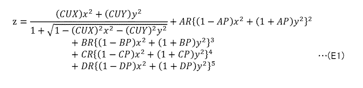
- the free-form surface data in FIG. 7 shows various coefficients of the following equation (E1) that define an anamorphic spherical surface as a free-form surface for the object-side surface of the second lens element L2.
- CUX, CUY, AR, AP, BR, BP, CR, CP, DR, and DP are coefficients.
- the sag amount z at the position of the (x, y) coordinate on the target surface is defined.
- each coordinate variable x, the y having a regularity that is dependent of the x 2 and y 2 only in the form of a weighted sum weighted by factor described above. That is, the anamorphic aspheric surface is a free-form surface that is rotationally asymmetric within the range of the regularity of the above equation (E1).
- FIG. 8 is a diagram illustrating free-form surface data of the fourth surface s4 in the imaging optical system IL1 according to Numerical Example 1.
- the free-form surface data in FIG. 8 indicates various coefficients of an XY polynomial that defines an XY polynomial surface as a free-form surface for the image-side surface of the second lens element L2.
- the XY polynomial is represented by the following equation (E2).
- c is a vertex curvature
- K is a conic constant
- c j is a coefficient
- j is an integer of 2 or more and 66 or less, and the sum of each j is calculated.
- the sag amount z at the position of the (x, y) coordinate on the target surface is defined more freely than the regularity of the anamorphic aspheric surface.
- FIGS. 9 and 10 are diagrams showing free-form surface data of the fifth and sixth surfaces s5 and s6 in the imaging optical system IL1 of Numerical Example 1, respectively.
- the free-form surface data in FIGS. 9 and 10 show various coefficients of the equation (E2) for the object-side and image-side surfaces of the third lens element L3, respectively, as in FIG.
- FIGS. 11 and 12 are diagrams showing aspherical data of the ninth and tenth surfaces s9 and s10 in the imaging optical system IL1 of Numerical Example 1, respectively.
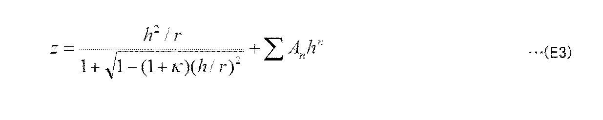
- Each aspherical surface data in FIGS. 11 and 12 shows various coefficients of the following equation (E3) for defining the shape of the aspherical surface for the object-side and image-side surfaces of the fifth lens element L5.
- h is a height in the radial direction
- K is a conic constant
- An is an n-th order aspherical coefficient.
- n is an even number from 4 to 20, and the sum of each n is calculated. According to the above equation (E3), the sag amount z at the radial height h on the target surface is rotationally symmetric.
- FIGS. 13 and 14 are diagrams showing free-form surface data of the fifteenth and sixteenth surfaces s15 and s16 in the imaging optical system IL1 of Numerical Example 1, respectively.
- the free-form surface data in FIG. 13 shows various coefficients of the equation (E1) for the object-side surface of the eighth lens element L8, as in FIG.
- the free-form surface data of FIG. 14 shows various coefficients of the equation (E2) for the image-side surface of the eighth lens element L8, as in FIG.
- FIG. 15 is an aberration diagram showing various aberrations of the imaging optical system IL1 in the present embodiment.
- the following aberration diagrams illustrate various longitudinal aberrations in the infinity in-focus state.
- FIG. 15A shows the spherical aberration “SA” in the imaging optical system IL1.
- FIGS. 15B, 15C, and 15D respectively show astigmatism “AST-V” in the Y direction, “AST-H” in the X direction, and “AST-H” in the diagonal direction. -D ".
- FIGS. 15A to 15D are each expressed in mm.
- the vertical axis in FIG. 15A is based on the pupil height.
- FIG. 15A shows characteristic curves of spherical aberration with respect to d-line, F-line, and c-line.
- the vertical axes in FIGS. 15B to 15D are based on the half angle of view.
- FIGS. 15B to 15D show astigmatism characteristic curves relating to the XZ section or the YZ along the X direction or the Y direction and the optical axis D1, respectively.
- FIG. 16 is a table showing the satisfaction of various conditions in the imaging optical system IL of the present embodiment.
- the chart shown in FIG. 16 shows that the imaging optical system IL of the present embodiment satisfies the following conditions (1) to (7) in each of Numerical Examples 1 to 3.
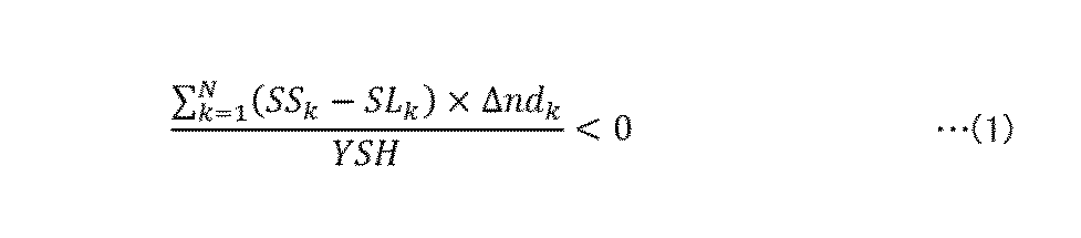
- Condition (1) is that the free-form surfaces of all free-form surfaces on the object side of the stop A in the imaging optical system IL generally satisfy the following conditional expression (1). According to the free-form surface lens on the object side of the aperture A, it is easy to control the light beam condensed on the aperture A from outside the imaging optical system IL, and to set an asymmetric angle of view.
- N is the total number of free-form surfaces on the object side (that is, on the ⁇ Z side) of the stop A.
- k is a number designating each free-form surface on the ⁇ Z side of the aperture A, and is an integer of 1 to N.
- the left side of the above equation (1) is the sum of the following difference (PS k ⁇ PL k ) between PS k and PL k for each free-form surface of the free-form surface lens on the ⁇ Z side of the stop A.
- PS k SS k ⁇ ⁇ nd k
- PL k SL k ⁇ ⁇ nd k
- SS k is the sag amount at the height YSH as a reference in the Y direction on the k-th free-form surface, and indicates a representative value of the sag amount on the short side of the free-form surface.
- the height YSH is 50% of the shortest image height in the imaging optical system IL, and is, for example, 1 / of the minor diameter Iy of the image circle Is in FIG.
- SL k is a representative value of the sag amount on the long side of the k-th free-form surface, and is the sag amount at the height YSH in the X direction.
- ⁇ nd k is a difference obtained by subtracting the refractive index on the ⁇ Z side from the refractive index on the + Z side of the k-th free-form surface.
- PS k indicates the tendency of power (that is, refractive power) in the YZ section of the lens according to the sag amount SS k on the short side of the k-th free-form surface.
- PL k indicates the tendency of power in the XZ section according to the sag amount SL k on the long side of the same surface. PS k and PL k will be described with reference to FIG.
- FIG. 17 illustrates a YZ section of a lens element Lk having a k-th free-form surface on the ⁇ Z side and a (k + 1) -th free-form surface on the + Z side.
- FIG. 17 illustrates a case where the lens element Lk is entirely biconvex and generates positive power on both surfaces.
- the sag SS k of surface on the -Z side of the lens element Lk is positive as shown in FIG. 17.
- the refractive index on the + Z side of the same surface is a refractive index nk based on the material of the lens element Lk
- the sag amount SS k + 1 on the + Z side surface of the lens element Lk becomes negative as shown in FIG.
- the sign of PS k corresponds to the sign of the power in the YZ section regardless of whether the corresponding free-form surface is on the + Z side or the ⁇ Z side of the lens element Lk. The same applies to the sign of PL k with respect to the XZ section.
- a difference between PS k and PL k occurs according to the difference between the sag amount SS k on the short side and the sag amount SL k on the long side.
- the difference (PS k ⁇ PL k ) is negative, the corresponding free-form surface tends to increase the power more negatively on the YZ section than on the XZ section of the lens element Lk, that is, on the shorter side than the longer side.
- the free-form surface on the ⁇ Z side of the stop A of the imaging optical system IL generally increases the power negatively on the shorter side than on the longer side. . Therefore, under the condition (1), the angle of view on the short side of the imaging optical system IL can be increased.
- FIG. 16 shows the calculation result of the left side of conditional expression (1).
- the calculation result “ ⁇ 0.0204” of the imaging optical system IL1 of the first embodiment is lower than the upper limit “0” shown on the right side of the above equation (1). .
- the imaging optical system IL1 of the first embodiment also satisfies the condition that the upper limit of conditional expression (1) is reduced from “0” to “ ⁇ 0.01”.
- the condition is hereinafter referred to as condition (1 '). According to the condition (1 '), the angle of view on the short side can be more easily widened, and the size of the optical system can be reduced.
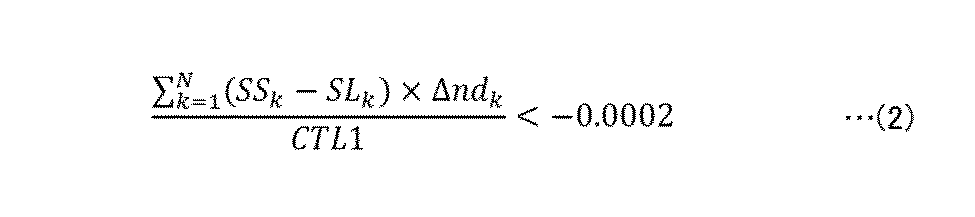
- the condition (2) is defined by the following conditional expression (2) based on the sum of the free-form surfaces of the free-form surface lens on the object side of the stop A in the same manner as the condition (1).
- ⁇ N k 1 ⁇ (SS k ⁇ SL k ) ⁇ ⁇ nd k ⁇ / CTL1 ⁇ 0.0002 (2)
- CTL1 is the thickness of the first lens element L1 closest to the ⁇ Z side in the imaging optical system IL.
- the sum of the left side of the above equation (2) is calculated in the same range as the conditional equation (1).
- FIG. 16 shows the calculation result of the left side of the above equation (2).
- condition (2) If the value exceeds the upper limit of conditional expression (2), it is conceivable that astigmatism becomes difficult to control or the optical system becomes large.
- the imaging optical system IL1 of the first embodiment falls below the upper limit value of the conditional expression (2) and satisfies the condition (2). Furthermore, the imaging optical system IL1 of the first embodiment satisfies the condition that the upper limit of conditional expression (2) is reduced to “ ⁇ 0.002”.
- the condition is hereinafter referred to as condition (2 '). According to the condition (2 '), the astigmatism of the imaging optical system IL1 can be easily controlled, and the size of the optical system can be easily reduced.
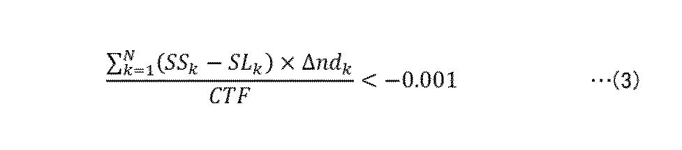
- the condition (3) is defined by the following conditional expression (3) based on the sum of the free-form surfaces of the free-form surface lens closer to the object side than the stop A, similarly to the condition (1).
- ⁇ N k 1 ⁇ (SS k ⁇ SL k ) ⁇ ⁇ nd k ⁇ / CTF ⁇ 0.001 (3)
- CTF is the thickness of the free-form surface lens closest to the ⁇ Z side in the imaging optical system IL.
- it is the thickness of the second lens element L2.
- the sum of the left side of the above equation (3) is calculated in the same range as the conditional equation (1).
- FIG. 16 shows the calculation result of the left side of the above equation (3).
- condition (3) the imaging optical system IL1 of the first embodiment satisfies the condition (3) as shown in FIG.
- the imaging optical system IL1 of Example 1 satisfies the condition that the upper limit of conditional expression (3) is reduced to “ ⁇ 0.01”.
- the condition is hereinafter referred to as condition (3 '). According to the condition (3 '), the angle of view on the short side of the imaging optical system IL1 can be easily enlarged, and the size of the optical system can be easily reduced.
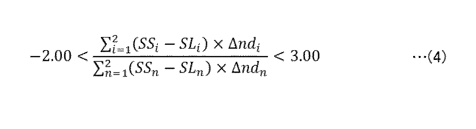
- Condition (4) is the following condition based on the sum of both surfaces of the free-form surface lens closest to the ⁇ Z side in the imaging optical system IL and the sum of both surfaces of the free-form surface lens closest to the + Z side of the stop A with respect to ⁇ Z side. It is defined by equation (4).
- SS i is the sag amount at the position of height YSH in the Y direction of the surface designated by i in the free-form surface lens.
- SL i is the sag amount of the i-th surface of the free-form surface lens at the same height YSH in the X direction.
- SL i and SS i are defined on each surface of the second lens element L2.
- SS n and SL n are sag amounts at the height YSH in the Y and X directions of the surface designated by n in the free-form surface lens.
- SL n and SS n are defined on each surface of the third lens element L3.
- conditional expression (4) if the value is below the lower limit, it becomes difficult to control astigmatism, whereas if the value exceeds the upper limit, it becomes difficult to enlarge the angle of view on the short side.
- the imaging optical system IL1 of the first embodiment satisfies the condition (4) as shown in FIG.
- the imaging optical system IL1 of Example 1 satisfies the condition that the lower limit of conditional expression (4) is raised to “0.00” and the upper limit is lowered to “2.00”.
- the condition is hereinafter referred to as condition (4 '). According to the condition (4 '), it is possible to easily control the astigmatism of the imaging optical system IL1 and enlarge the angle of view on the short side.
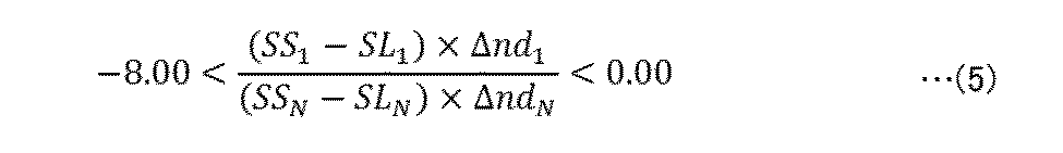
- the condition (5) is defined by the following conditional expression (5) regarding the free-form surface closest to the ⁇ Z side in the imaging optical system IL and the free-form surface closest to the + Z side on the ⁇ Z side of the stop A.
- SL 1 and SS 1 are the sag amounts at the positions of the height YSH in the X and Y directions of the free-form surface closest to the ⁇ Z side, respectively.
- SL N and SS N are the sag amounts at the height YSH in the X and Y directions of the free-form surface closest to the + Z side of the stop A on the ⁇ Z side.
- SL 1 and SS 1 are defined on the ⁇ Z side surface of the second lens element L2
- SL N and SS N are defined on the + Z side surface of the third lens element L3.
- conditional expression (5) if the value is below the lower limit value, the size of the optical system is increased.
- the imaging optical system IL1 of the first embodiment satisfies the condition (5).
- the imaging optical system IL1 of Example 1 satisfies the condition that the lower limit of conditional expression (5) is raised to “ ⁇ 6.00” and the upper limit is reduced to “ ⁇ 2.00”.
- the condition is hereinafter referred to as condition (5 ').
- condition (5 ′) it is possible to easily reduce the size of the imaging optical system IL1 and increase the angle of view on the short side.
- conditional expression (6) is defined by the following conditional expression (6) regarding the refractive index of the free-form surface lens on the ⁇ Z side of the stop A in the imaging optical system IL. 1 ⁇ nd1 / ndN ⁇ 1.3 (6)
- nd1 is the refractive index for the d-line of the free-form surface lens closest to the ⁇ Z side.
- ndN is the refractive index for the d-line of the free-form surface lens closest to the + Z side on the ⁇ Z side than the stop A.
- nd1 is the refractive index of the second lens element L2
- ndN is the refractive index of the third lens element L3.
- conditional expression (6) when the value goes below the lower limit, it becomes difficult to control astigmatism. On the other hand, when the value goes above the upper limit, it becomes difficult to control chromatic aberration of magnification. On the other hand, according to the calculation results shown in FIG. 16, for example, the imaging optical system IL1 of the first embodiment satisfies the condition (6). This makes it possible to avoid a situation where it becomes difficult to control astigmatism and chromatic aberration of magnification.
- conditional expression (7) is defined by the following conditional expression (7) regarding the refractive index ndN of the free-form surface lens closest to the + Z side on the ⁇ Z side of the stop A. 1.45 ⁇ ndN ⁇ 1.80 (7)
- conditional expression (7) if the value is below the lower limit, it is difficult to control the curvature of field, while if the value is above the upper limit, it becomes difficult to control the chromatic aberration of magnification.
- the imaging optical system IL1 of Example 1 satisfies the condition (7). Furthermore, the imaging optical system IL1 of Example 1 satisfies the condition that the lower limit of conditional expression (7) is raised to “1.50” and the upper limit is reduced to “1.60”.
- this condition is referred to as condition (7 '). According to the condition (7 '), it is possible to easily control the curvature of field and the chromatic aberration of magnification.
- the imaging optical system IL according to the present embodiment can be implemented in various forms without being limited to the imaging optical system IL1 of Example 1 described above.
- the imaging optical system IL1 of Example 1 has two free-form surface lenses on the object side of the stop A, but the imaging optical system IL of the present embodiment has three or more free-form surface lenses than the stop A. It may be arranged on the object side.
- Example 2 In a second embodiment, an example of the imaging optical system IL in which the number of free-form surface lenses on the object side of the stop A is three will be described.
- the imaging optical system IL2 according to the second embodiment will be described with reference to FIGS.
- FIG. 18 illustrates a configuration of an imaging optical system IL2 according to the second embodiment.
- FIGS. 18A and 18B show lens arrangement diagrams of the imaging optical system IL2, similarly to FIGS. 3A and 3B.
- the imaging optical system IL2 of the second embodiment includes a first to seventh lens elements L1 to L7 arranged in order similarly to the first embodiment, and a stop A arranged between the fourth and fifth lens elements L4 and L5.
- the first lens element L1 is formed of a free-form surface lens having an XY polynomial surface on the image plane side.
- the second and third lens elements L2 and L3 are constituted by free-form lenses having XY polynomial surfaces on both surfaces.
- the seventh lens element L7 closest to the image plane is formed of a free-form surface lens having XY polynomial surfaces on both surfaces. Numerical examples corresponding to the imaging optical system IL2 of the second embodiment are shown in FIGS.
- FIG. 19 is a diagram showing surface data of the imaging optical system IL2 in Numerical Example 2.
- FIG. 20 is a diagram illustrating various data of the imaging optical system IL2 in the present embodiment.
- FIGS. 19 and 20 show the respective data as in FIGS. 5 and 6 of Numerical Example 1.
- FIGS. 21 to 25 are diagrams showing free-form surface data of the second to sixth surfaces s2 to s6 in the imaging optical system IL2 of the present embodiment.
- the free-form surface data in FIG. 21 shows various coefficients of the equation (E2) for the image-side surface of the first lens element L1 as in the first embodiment.
- FIGS. 22 to 25 show free-form surface data on both surfaces of the second and third lens elements L2 and L3, respectively.
- FIGS. 26 and 27 show aspherical data of the seventh and eighth surfaces s7 and s8 in the imaging optical system IL2 of the present embodiment, similarly to FIGS. 28 and 29 show free-form surface data of the 13th and 14th surfaces s13 and s14 in the imaging optical system IL2, respectively, as in FIG. 14 and the like.
- FIG. 30 shows the relationship between the angle of view and the image point P2 in the imaging optical system IL2 of the present embodiment based on the above-described Numerical Embodiment 2. As shown in FIG. 30, also with the imaging optical system IL2 of the present embodiment, the angle of view in the Y direction can be expanded as in the first embodiment.
- FIG. 31 shows various aberrations of the imaging optical system IL2 in the present embodiment.
- FIGS. 31 (a), (b), (c), and (d) show aberration diagrams of the imaging optical system IL2 in the present embodiment, similarly to FIGS. 15 (a) to (d).
- the imaging optical system IL2 of the present embodiment satisfies the above-described conditions (1) to (7). Further, the imaging optical system IL2 of this embodiment satisfies the condition that the lower limit of the condition (6) is increased to “1.05” and the upper limit is reduced to “1.2”.
- the condition is hereinafter referred to as condition (6 '). According to the condition (6 '), the astigmatism and the chromatic aberration of magnification of the imaging optical system IL2 can be easily controlled.
- Example 3 An imaging optical system IL3 according to a third embodiment will be described with reference to FIGS.
- FIG. 32 illustrates a configuration of an imaging optical system IL3 according to the third embodiment.
- FIGS. 32A and 32B show lens arrangement diagrams of the imaging optical system IL3, similarly to FIGS. 3A and 3B, respectively.
- the imaging optical system IL3 includes a first to a tenth lens elements L1 to L10 arranged in order similarly to the first embodiment, and an aperture A arranged between the fifth and sixth lens elements L5 and L6.
- the first lens element L1 closest to the object has a biconcave shape instead of a fisheye lens as in the first embodiment.
- the first lens element L1 of this embodiment has, for example, an aspherical surface on the image plane side, and is constituted by a rotationally symmetric aspherical lens.
- the second and third lens elements L2 and L3 are free-form lenses having free-form surfaces on both surfaces as shown in FIG.
- the fourth lens element L4 is a spherical lens having a biconvex shape.
- the fifth lens element L5 is a spherical lens having a positive meniscus shape, and is arranged with the convex surface facing the object side.
- the sixth lens element L6 is a spherical lens having a biconvex shape, and is joined to the seventh lens element L7.
- the seventh lens element L7 is a spherical lens having a biconcave shape.
- the eighth lens element L8 is an aspheric lens having an aspheric surface on the object side.
- the ninth lens element L9 is a free-form surface lens having free-form surfaces on both sides.
- the tenth lens element L10 is a free-form surface lens having free-form surfaces on both sides. Numerical examples corresponding to the imaging optical system IL3 of the third embodiment are shown in FIGS.
- FIG. 33 is a diagram showing surface data of the imaging optical system IL3 in Numerical Example 3.
- FIG. 34 is a diagram illustrating various data of the imaging optical system IL3 in the present embodiment.
- FIGS. 33 and 34 show respective data similarly to FIGS. 5 and 6 of Numerical Example 1.
- FIG. 35 is a diagram showing aspherical surface data of the second surface s2 in the imaging optical system IL3 of the present embodiment.
- the aspherical data in FIG. 35 shows various coefficients of the equation (E3) for the image-side surface of the first lens element L1 as in Numerical Example 1.
- FIGS. 36 to 39 are diagrams showing free-form surface data of the third to sixth surfaces s3 to s6 in the imaging optical system IL3 of this embodiment, respectively. 36 to 39 show various coefficients of the equation (E2) as in Numerical Example 1.
- FIG. 40 shows aspherical data of the fifteenth surface s15 in the imaging optical system IL3 of the present embodiment
- FIG. 41 to 44 are diagrams showing free-form surface data of the 17th to 20th surfaces s17 to s20 in the imaging optical system IL3, respectively.
- FIGS. 41 to 44 show free-form surface data on both surfaces of the ninth and tenth lens elements L9 and L10, respectively, as in FIGS. 36 to 39.
- FIG. 45 shows the relationship between the angle of view and the image point P3 in the imaging optical system IL3 according to the present embodiment, based on the third numerical embodiment described above.
- FIG. 46 shows various aberrations of the imaging optical system IL3 in the present embodiment.
- FIGS. 46 (a), (b), (c), and (d) show aberration diagrams of the image pickup optical system IL3 in the present embodiment, similarly to FIGS. 15 (a) to (d).
- the imaging optical system IL3 of the present embodiment satisfies the above-described conditions (1) to (7) as shown in FIG. As described above, also with the imaging optical system IL3 of the present embodiment, it is possible to easily widen the angle of view in the short side direction, as in the first embodiment.
- the rectangular imaging surface is illustrated in FIG. 2, but the imaging surface of the imaging element 12 is not limited to this.
- the imaging surface of the imaging element 12 may have various rectangular shapes other than a rectangular shape, or may be partially masked. Further, the imaging surface of the imaging element 12 may be curved. The same effect as that of the first embodiment can be obtained for such an image sensor 12 by the imaging optical system IL of the present embodiment.
- the long side Dx and the short side Dy of the image sensor 12 of the present embodiment need not be orthogonal to each other, and may intersect at various angles.
- the imaging element 12 may have two sides having the same length instead of the long side Dx and the short side Dy.
- the first and second directions defined by the major axis Ix and the minor axis Iy of the image circle Is not necessarily orthogonal to each other, and may intersect at various angles.
- the diameters of the image circle Is in the first and second directions may be the same.
- the image circle Is does not necessarily have to be distorted from a circle.
- the XY polynomial surface and the anamorphic aspheric surface are illustrated as examples of the free-form surface.
- the free-form surface is not limited to the above, and may be, for example, a toric surface.
- the imaging optical system of the present embodiment may include two or more free-form surfaces that are not anamorphic and are closer to the object side than the stop A. Free-form surfaces that are not anamorphic include XY polynomial surfaces but do not include anamorphic aspheric surfaces.
- a free-form surface that is not anamorphic may not have, for example, a plane of symmetry.
- the imaging system 10 of the present embodiment is applicable to various uses, for example, an in-vehicle use.
- the in-vehicle camera may be configured so that the imaging device 11 captures a scene behind a moving object such as a vehicle.
- the imaging device 11 as an in-vehicle camera is not limited to being located behind a moving object, and may be applied to an application for imaging various scenes such as ahead or sideways.
- the imaging system 10 is not limited to a vehicle-mounted use, and can be applied to, for example, a monitoring camera that monitors various situations.
- a first aspect according to the present disclosure is an imaging optical system having an image circle that forms an image on an imaging element.
- the imaging optical system includes a plurality of lens elements arranged from the object side to the image plane side, and a stop arranged between the plurality of lens elements.
- the plurality of lens elements include a free-form lens having a free-form surface that is asymmetric between a first direction and a second direction that intersect each other. At least two free-form lenses are disposed on the object side of the stop.
- the angle of view in a specific direction can be easily widened by each free-form surface of the plurality of free-form surfaces on the object side of the stop.
- the diameter in the first direction is equal to or larger than the diameter in the second direction.
- the imaging optical system satisfies the following conditional expression (1) based on the sum of free-form surfaces of the free-form surface lens on the object side of the stop.
- N the total number of free-form surfaces on the free-form surface lens on the object side of the stop k: the number SL k indicating each free-form surface in the total number N of free-form surfaces: the height of the k-th free-form surface in the first direction is the shortest image height
- Difference YSH obtained by subtracting the refractive index: 50% of the shortest image height.
- the diameter in the first direction is equal to or larger than the diameter in the second direction.
- the imaging optical system satisfies the following conditional expression (2) based on the sum of free-form surfaces of the free-form surface lens on the object side of the stop.
- N the total number of free-form surfaces on the free-form surface lens on the object side of the stop k: the number SL k indicating each free-form surface in the total number N of free-form surfaces: the height of the k-th free-form surface in the first direction is the shortest image height
- Difference CTL1 from which the refractive index has been subtracted is the thickness of the lens element closest to the object.
- the diameter in the first direction is equal to or larger than the diameter in the second direction.
- the imaging optical system satisfies the following conditional expression (3) based on the sum of free-form surfaces of the free-form surface lens on the object side of the stop.
- N the total number of free-form surfaces on the free-form surface lens on the object side of the stop k: the number SL k indicating each free-form surface in the total number N of free-form surfaces: the height of the k-th free-form surface in the first direction is the shortest image height
- Difference CTF obtained by subtracting the refractive index The thickness of the free-form surface lens closest to the object. This makes it possible to increase the angle of view in the second direction while avoiding an increase in the size of the optical system.
- the diameter in the first direction is equal to or larger than the diameter in the second direction.
- the imaging optical system satisfies the following conditional expression (4) based on the sum of both surfaces of the free-form surface lens closest to the object side and the sum of both surfaces of the free-form surface lens closest to the image surface side of the stop.
- i number SL i indicating each surface of the free-form surface lens closest to the object side i : sag amount SS at a position where the height of the i-th surface of the free-form surface lens closest to the object side in the first direction is 50% of the shortest image height i : sag amount ⁇ nd i at a position where the height of the i-th surface in the second direction is 50% of the shortest image height: difference between the refractive index on the image surface side and the refractive index on the object side of the i-th surface n: number SL n indicating each surface of the free-form surface lens closest to the image plane SL n : sag at a position where the height of the n-th surface of the free-form surface lens closest to the image surface in the first direction is 50% of the shortest image height Amount SS n : sag amount at a position where the height of the n-th surface in the second direction in the second direction is 50% of
- the diameter in the first direction is equal to or larger than the diameter in the second direction.
- the imaging optical system satisfies the following conditional expression (5).
- SL 1 sag amount SS 1 where the height of the free-form surface closest to the object side in the first direction is 50% of the shortest image height: the height of the free-form surface closest to the object side in the second direction is 50 which is the shortest image height %
- Sag amount ⁇ nd 1 difference SL N obtained by subtracting the refractive index on the object side from the refractive index on the image side rather than the free-form surface closest to the object side
- SL N the free-form surface closest to the image side on the object side than the stop
- the imaging optical system of the first aspect satisfies the following conditional expression (6). 1 ⁇ nd1 / ndN ⁇ 1.3 (6) here, nd1: Refractive index for d-line of the free-form surface lens closest to the object side ndN: Refractive index for the d-line of the free-form surface lens closest to the image side on the object side of the stop.
- nd1 Refractive index for d-line of the free-form surface lens closest to the object side
- ndN Refractive index for the d-line of the free-form surface lens closest to the image side on the object side of the stop.
- the imaging optical system of the first aspect satisfies the following conditional expression (7). 1.45 ⁇ ndN ⁇ 1.80 (7) here, ndN: a refractive index for the d-line of the free-form surface lens closest to the image plane on the object side of the stop. Accordingly, it is possible to enlarge the angle of view in the second direction while avoiding a situation where it is difficult to control the field curvature and the chromatic aberration of magnification.
- the free-form surface lenses on the object side of the stop are adjacent to each other. This makes it easy to control the behavior of the asymmetric component of the light beam, and can improve the asymmetric component of the field curvature.
- the plurality of lens elements include a free-form surface lens disposed closer to the image plane than the stop. This makes it easy to control the resolution, for example, to increase the resolution near the center of the image plane.
- the lens element closest to the object is rotationally symmetric with respect to the optical axis.
- the sign of (SS k -SL k ) is the same on all free-form surfaces of the free-form surface lens on the object side of the stop.
- k number SL k indicating each free-form surface of the free-form surface of the free-form surface lens on the object side of the stop: sag amount SS k at a position where the height of the k-th free-form surface in the first direction is 50% of the shortest image height.
- a thirteenth aspect is an imaging device including the imaging optical system according to any one of the first to twelfth aspects, and an imaging element.
- the imaging element captures an image formed by the imaging optical system.
- the imaging element has a first side corresponding to the first direction and a second side corresponding to the second direction and having a length equal to or shorter than the first side. With the imaging optical system, the angle of view in a specific direction of the imaging device can be easily widened.
- a fourteenth aspect is an imaging system including the imaging device of the thirteenth aspect and an image processing unit.
- the image processing unit performs image processing on an image captured by the imaging device of the imaging device.
- the imaging optical system makes it easy to increase the angle of view in a specific direction in the imaging system.
- the imaging system according to the present disclosure can be applied to various imaging applications, for example, an in-vehicle camera, a surveillance camera, a Web camera, a digital camera, and the like. Further, the imaging optical system according to the present disclosure may be provided in an interchangeable lens device.
Landscapes
- Physics & Mathematics (AREA)
- General Physics & Mathematics (AREA)
- Optics & Photonics (AREA)
- Lenses (AREA)
Abstract
Description
以下、本開示に係る撮像光学系、撮像装置及び撮像システムの実施形態1を、図面を用いて説明する。
本実施形態に係る撮像システムについて、図1を用いて説明する。図1は、本実施形態に係る撮像システム10の構成を示す図である。
本実施形態に係る撮像光学系ILが具体的に実施される一例として、撮像光学系ILの実施例1~3を以下説明する。
図3~15を用いて、実施例1に係る撮像光学系IL1について説明する。

以上の撮像光学系IL1の数値実施例1を用いて、本実施形態に係る撮像光学系ILが満たす各種条件について、図16,17を参照して説明する。
PSk=SSk×Δndk
PLk=SLk×Δndk
ここで、SSkは、k番目の自由曲面におけるY方向において基準とする高さYSHの箇所のサグ量であり、当該自由曲面における短辺側のサグ量の代表的な値を示す。高さYSHは、撮像光学系ILにおける最短像高の50%であり、例えば図2のイメージサークルIsの短径Iyの1/4である。SLkは、k番目の自由曲面における長辺側のサグ量の代表値であって、X方向における高さYSHの箇所のサグ量である。Δndkは、k番目の自由曲面よりも+Z側における屈折率から-Z側における屈折率を差し引いた差分である。
ΣN k=1{(SSk-SLk)×Δndk}/CTL1<-0.0002 …(2)
ここで、CTL1は、撮像光学系ILにおいて最も-Z側となる第1レンズ素子L1の厚みである。上式(2)の左辺の総和は、条件式(1)と同様の範囲で計算される。上式(2)の左辺の計算結果を図16に示す。
ΣN k=1{(SSk-SLk)×Δndk}/CTF<-0.001 …(3)
ここで、CTFは、撮像光学系ILにおいて最も-Z側の自由曲面レンズの厚みであり、例えば実施例1の撮像光学系IL1では、第2レンズ素子L2の厚みである。上式(3)の左辺の総和は、条件式(1)と同様の範囲で計算される。上式(3)の左辺の計算結果を図16に示す。

1≦nd1/ndN<1.3 …(6)
ここで、nd1は、最も-Z側の自由曲面レンズのd線に対する屈折率である。ndNは、絞りAよりも-Z側において最も+Z側の自由曲面レンズのd線に対する屈折率である。例えば、実施例1では、nd1は第2レンズ素子L2の屈折率であり、ndNは第3レンズ素子L3の屈折率である。
1.45<ndN<1.80 …(7)
実施例2では、絞りAよりも物体側の自由曲面レンズが3枚である撮像光学系ILの一例を説明する。図18~31を用いて、実施例2の撮像光学系IL2について説明する。
図32~46を用いて、実施例3の撮像光学系IL3について説明する。
以上のように、本出願において開示する技術の例示として、実施形態1を説明した。しかしながら、本開示における技術は、これに限定されず、適宜、変更、置換、付加、省略などを行った実施の形態にも適用可能である。また、上記各実施形態で説明した各構成要素を組み合わせて、新たな実施の形態とすることも可能である。そこで、以下、他の実施形態を例示する。
以下、本開示に係る各種態様を例示する。

N:絞りよりも物体側の自由曲面レンズにおける自由曲面の総数
k:総数Nの自由曲面における各自由曲面を示す番号
SLk:k番目の自由曲面の第1方向における高さが最短像高の50%の箇所のサグ量
SSk:当該自由曲面の第2方向における高さが最短像高の50%の箇所のサグ量
Δndk:当該自由曲面よりも像面側における屈折率から物体側における屈折率を差し引いた差分
YSH:最短像高の50%の高さ
である。これにより、撮像光学系の絞りよりも物体側の自由曲面が総合的に、第1方向よりも第2方向においてパワーを負に強めて、第2方向における画角を拡げることができる。

N:絞りよりも物体側の自由曲面レンズにおける自由曲面の総数
k:総数Nの自由曲面における各自由曲面を示す番号
SLk:k番目の自由曲面の第1方向における高さが最短像高の50%の箇所のサグ量
SSk:当該自由曲面の第2方向における高さが最短像高の50%の箇所のサグ量
Δndk:当該自由曲面よりも像面側における屈折率から物体側における屈折率を差し引いた差分
CTL1:最も物体側のレンズ素子の厚み
である。これにより、第2方向における画角を拡げる際に、非点収差を抑制したり光学系の大型化を回避したりすることができる。
N:絞りよりも物体側の自由曲面レンズにおける自由曲面の総数
k:総数Nの自由曲面における各自由曲面を示す番号
SLk:k番目の自由曲面の第1方向における高さが最短像高の50%の箇所のサグ量
SSk:当該自由曲面の第2方向における高さが最短像高の50%の箇所のサグ量
Δndk:当該自由曲面よりも像面側における屈折率から物体側における屈折率を差し引いた差分
CTF:最も物体側の自由曲面レンズの厚み
である。これにより、光学系の大型化を回避しながら、第2方向における画角を拡げることができる。

i:最も物体側の自由曲面レンズの各面を示す番号
SLi:最も物体側の自由曲面レンズのi番目の面の第1方向における高さが最短像高の50%の箇所のサグ量
SSi:i番目の面の第2方向における高さが最短像高の50%の箇所のサグ量
Δndi:i番目の面よりも像面側における屈折率から物体側における屈折率を差し引いた差分
n:最も像面側の自由曲面レンズの各面を示す番号
SLn:最も像面側の自由曲面レンズのn番目の面の第1方向における高さが最短像高の50%の箇所のサグ量
SSn:n番目の面の第2方向における高さが最短像高の50%の箇所のサグ量
Δndn:n番目の面よりも像面側における屈折率から物体側における屈折率を差し引いた差分
である。これにより、非点収差を制御すると共に第2方向の画角拡大を行うことができる。

SL1:最も物体側の自由曲面の第1方向における高さが最短像高の50%の箇所のサグ量
SS1:最も物体側の自由曲面の第2方向における高さが最短像高の50%の箇所のサグ量
Δnd1:最も物体側の自由曲面よりも像面側における屈折率から物体側における屈折率を差し引いた差分
SLN:絞りよりも物体側において最も像面側の自由曲面の第1方向における高さが最短像高の50%の箇所のサグ量
SSN:最も像面側の自由曲面の第2方向における高さが最短像高の50%の箇所のサグ量
ΔndN:最も像面側の自由曲面よりも像面側における屈折率から物体側における屈折率を差し引いた差分
である。これにより、光学系の小型化を図りながら第2方向の画角拡大を行うことができる。
1≦nd1/ndN<1.3 …(6)
ここで、
nd1:最も物体側の自由曲面レンズのd線に対する屈折率
ndN:絞りよりも物体側において最も像面側の自由曲面レンズのd線に対する屈折率
である。これにより、非点収差及び倍率色収差の制御が困難になる事態を回避しながら、第2方向の画角拡大を行うことができる。
1.45<ndN<1.80 …(7)
ここで、
ndN:絞りよりも物体側において最も像面側の自由曲面レンズのd線に対する屈折率
である。これにより、像面湾曲及び倍率色収差の制御が困難になる事態を回避しながら、第2方向の画角拡大を行うことができる。
k:絞りよりも物体側の自由曲面レンズの自由曲面における各自由曲面を示す番号
SLk:k番目の自由曲面の第1方向における高さが最短像高の50%の箇所のサグ量
SSk:当該自由曲面の第2方向における高さが最短像高の50%の箇所のサグ量
Δndk:当該自由曲面よりも像面側における屈折率から物体側における屈折率を差し引いた差分
である。これにより、絞りよりも物体側の自由曲面において第2の方向における画角を拡げる際に、入射する光線を徐々に曲げて、収差の発生を抑制することができる。
Claims (14)
- 撮像素子に結像するイメージサークルを有する撮像光学系であって、
物体側から像面側に並んだ複数のレンズ素子と、前記複数のレンズ素子の間に配置された絞りとを備え、
前記複数のレンズ素子は、互いに交差する第1方向と第2方向との間で非対称な自由曲面を有する自由曲面レンズを含み、
少なくとも2枚の自由曲面レンズが、前記絞りよりも物体側に配置された
撮像光学系。 - 前記イメージサークルにおいて、前記第1方向の径が前記第2方向の径以上であり、
前記絞りよりも物体側の自由曲面レンズの自由曲面に関する総和に基づく以下の条件式(1)を満たし、

N:前記絞りよりも物体側の自由曲面レンズにおける自由曲面の総数
k:総数Nの自由曲面における各自由曲面を示す番号
SLk:k番目の自由曲面の前記第1方向における高さが最短像高の50%の箇所のサグ量
SSk:当該自由曲面の前記第2方向における高さが最短像高の50%の箇所のサグ量
Δndk:当該自由曲面よりも像面側における屈折率から物体側における屈折率を差し引いた差分
YSH:最短像高の50%の高さ
である、請求項1に記載の撮像光学系。 - 前記イメージサークルにおいて、前記第1方向の径が前記第2方向の径以上であり、
前記絞りよりも物体側の自由曲面レンズの自由曲面に関する総和に基づく以下の条件式(2)を満たし、
N:前記絞りよりも物体側の自由曲面レンズにおける自由曲面の総数
k:総数Nの自由曲面における各自由曲面を示す番号
SLk:k番目の自由曲面の前記第1方向における高さが最短像高の50%の箇所のサグ量
SSk:当該自由曲面の前記第2方向における高さが最短像高の50%の箇所のサグ量
Δndk:当該自由曲面よりも像面側における屈折率から物体側における屈折率を差し引いた差分
CTL1:最も物体側のレンズ素子の厚み
である、請求項1に記載の撮像光学系。 - 前記イメージサークルにおいて、前記第1方向の径が前記第2方向の径以上であり、
前記絞りよりも物体側の自由曲面レンズの自由曲面に関する総和に基づく以下の条件式(3)を満たし、

N:前記絞りよりも物体側の自由曲面レンズにおける自由曲面の総数
k:総数Nの自由曲面における各自由曲面を示す番号
SLk:k番目の自由曲面の前記第1方向における高さが最短像高の50%の箇所のサグ量
SSk:当該自由曲面の前記第2方向における高さが最短像高の50%の箇所のサグ量
Δndk:当該自由曲面よりも像面側における屈折率から物体側における屈折率を差し引いた差分
CTF:最も物体側の自由曲面レンズの厚み
である、請求項1に記載の撮像光学系。 - 前記イメージサークルにおいて、前記第1方向の径が前記第2方向の径以上であり、
最も物体側の自由曲面レンズの両面に関する総和と、前記絞りよりも物体側において最も像面側の自由曲面レンズの両面に関する総和とに基づく以下の条件式(4)を満たし、

i:前記最も物体側の自由曲面レンズの各面を示す番号
SLi:前記最も物体側の自由曲面レンズのi番目の面の前記第1方向における高さが最短像高の50%の箇所のサグ量
SSi:前記i番目の面の前記第2方向における高さが最短像高の50%の箇所のサグ量
Δndi:前記i番目の面よりも像面側における屈折率から物体側における屈折率を差し引いた差分
n:前記最も像面側の自由曲面レンズの各面を示す番号
SLn:前記最も像面側の自由曲面レンズのn番目の面の前記第1方向における高さが最短像高の50%の箇所のサグ量
SSn:前記n番目の面の前記第2方向における高さが最短像高の50%の箇所のサグ量
Δndn:前記n番目の面よりも像面側における屈折率から物体側における屈折率を差し引いた差分
である、請求項1に記載の撮像光学系。 - 前記イメージサークルにおいて、前記第1方向の径が前記第2方向の径以上であり、
以下の条件式(5)を満たし、
SL1:最も物体側の自由曲面の前記第1方向における高さが最短像高の50%の箇所のサグ量
SS1:前記最も物体側の自由曲面の前記第2方向における高さが最短像高の50%の箇所のサグ量
Δnd1:前記最も物体側の自由曲面よりも像面側における屈折率から物体側における屈折率を差し引いた差分
SLN:前記絞りよりも物体側において最も像面側の自由曲面の前記第1方向における高さが最短像高の50%の箇所のサグ量
SSN:前記最も像面側の自由曲面の前記第2方向における高さが最短像高の50%の箇所のサグ量
ΔndN:前記最も像面側の自由曲面よりも像面側における屈折率から物体側における屈折率を差し引いた差分
である、請求項1に記載の撮像光学系。 - 以下の条件式(6)を満たし、
1≦nd1/ndN<1.3 …(6)
ここで、
nd1:最も物体側の自由曲面レンズのd線に対する屈折率
ndN:前記絞りよりも物体側において最も像面側の自由曲面レンズのd線に対する屈折率
である、請求項1に記載の撮像光学系。 - 以下の条件式(7)を満たし、
1.45<ndN<1.80 …(7)
ここで、
ndN:前記絞りよりも物体側において最も像面側の自由曲面レンズのd線に対する屈折率
である、請求項1に記載の撮像光学系。 - 前記絞りよりも物体側の自由曲面レンズが、互いに隣り合う
請求項1に記載の撮像光学系。 - 前記複数のレンズ素子は、前記絞りよりも像面側に配置された自由曲面レンズを含む
請求項1に記載の撮像光学系。 - 最も物体側のレンズ素子は、光軸に対して回転対称である
請求項1に記載の撮像光学系。 - 前記絞りよりも物体側の自由曲面レンズの全ての自由曲面において、(SSk-SLk)の符号が同じであり、
ここで、
k:前記絞りよりも物体側の自由曲面レンズの自由曲面における各自由曲面を示す番号
SLk:k番目の自由曲面の前記第1方向における高さが最短像高の50%の箇所のサグ量
SSk:当該自由曲面の前記第2方向における高さが最短像高の50%の箇所のサグ量
Δndk:当該自由曲面よりも像面側における屈折率から物体側における屈折率を差し引いた差分
である、請求項1に記載の撮像光学系。 - 請求項1~12のいずれか1項に記載の撮像光学系と、
前記撮像光学系によって結像される像を撮像する撮像素子とを備え、
前記撮像素子は、前記第1方向に対応する第1辺と、前記第2方向に対応する第2辺であって、前記第1辺以下の長さを有する第2辺とを有する
撮像装置。 - 請求項13に記載の撮像装置と、
前記撮像装置の撮像素子によって撮像された画像に画像処理を実行する画像処理部と
を備えた撮像システム。
Priority Applications (4)
| Application Number | Priority Date | Filing Date | Title |
|---|---|---|---|
| CN201980035371.4A CN112166363B (zh) | 2018-07-18 | 2019-06-13 | 摄像光学系统、摄像装置以及摄像系统 |
| EP19837779.8A EP3825751B1 (en) | 2018-07-18 | 2019-06-13 | Imaging optical system, imaging device, and imaging system |
| JP2020530939A JP7228785B2 (ja) | 2018-07-18 | 2019-06-13 | 撮像光学系、撮像装置及び撮像システム |
| US17/117,658 US12032145B2 (en) | 2018-07-18 | 2020-12-10 | Imaging optical system, imaging device, and imaging system |
Applications Claiming Priority (2)
| Application Number | Priority Date | Filing Date | Title |
|---|---|---|---|
| JP2018135302 | 2018-07-18 | ||
| JP2018-135302 | 2018-07-18 |
Related Child Applications (1)
| Application Number | Title | Priority Date | Filing Date |
|---|---|---|---|
| US17/117,658 Continuation US12032145B2 (en) | 2018-07-18 | 2020-12-10 | Imaging optical system, imaging device, and imaging system |
Publications (1)
| Publication Number | Publication Date |
|---|---|
| WO2020017201A1 true WO2020017201A1 (ja) | 2020-01-23 |
Family
ID=69165033
Family Applications (1)
| Application Number | Title | Priority Date | Filing Date |
|---|---|---|---|
| PCT/JP2019/023536 Ceased WO2020017201A1 (ja) | 2018-07-18 | 2019-06-13 | 撮像光学系、撮像装置及び撮像システム |
Country Status (5)
| Country | Link |
|---|---|
| US (1) | US12032145B2 (ja) |
| EP (1) | EP3825751B1 (ja) |
| JP (1) | JP7228785B2 (ja) |
| CN (1) | CN112166363B (ja) |
| WO (1) | WO2020017201A1 (ja) |
Cited By (4)
| Publication number | Priority date | Publication date | Assignee | Title |
|---|---|---|---|---|
| WO2021260665A1 (en) | 2020-06-26 | 2021-12-30 | Immervision Inc. | Wide-angle lens with freeform surface |
| WO2022021455A1 (zh) * | 2020-07-27 | 2022-02-03 | 常州市瑞泰光电有限公司 | 摄像光学镜头 |
| WO2022215293A1 (ja) * | 2021-04-06 | 2022-10-13 | パナソニックIpマネジメント株式会社 | レンズ系、撮像装置および撮像システム |
| US12085695B2 (en) | 2021-03-05 | 2024-09-10 | Largan Precision Co., Ltd. | Optical imaging lens system including ten lenses of ++−++−+−+−, ++−++−−−+−, ++−+−+−+−−, ++−+++−+−−, −+−+++−+−−, ++−++−−++−, ++−+−−+−+−, or ++−+−−−−+− refractive powers, image capturing unit and electronic device |
Families Citing this family (3)
| Publication number | Priority date | Publication date | Assignee | Title |
|---|---|---|---|---|
| CN110730922B (zh) * | 2017-06-13 | 2021-10-26 | 松下知识产权经营株式会社 | 透镜系统、摄像机系统以及摄像系统 |
| US12339427B2 (en) * | 2019-11-22 | 2025-06-24 | Foshan Limited | Equirectangular lens for virtual reality video |
| CN111736308B (zh) * | 2020-07-27 | 2020-12-22 | 诚瑞光学(常州)股份有限公司 | 摄像光学镜头 |
Citations (4)
| Publication number | Priority date | Publication date | Assignee | Title |
|---|---|---|---|---|
| WO2003010599A1 (fr) | 2001-07-20 | 2003-02-06 | 6115187 Canada Inc. | Procede de capture d'une image panoramique au moyen d'un capteur d'image de forme rectangulaire |
| JP2007163549A (ja) * | 2005-12-09 | 2007-06-28 | Konica Minolta Opto Inc | 超広角撮像光学系、超広角撮像レンズ装置及び撮像装置 |
| JP2008292800A (ja) * | 2007-05-25 | 2008-12-04 | Topcon Corp | アナモルフィックレンズ、撮像装置及び監視装置 |
| JP2010276755A (ja) * | 2009-05-27 | 2010-12-09 | Konica Minolta Opto Inc | 超広角アナモルフィックレンズ |
Family Cites Families (13)
| Publication number | Priority date | Publication date | Assignee | Title |
|---|---|---|---|---|
| JPS53127722A (en) * | 1977-04-13 | 1978-11-08 | Fuji Photo Film Co Ltd | Anamorphic lens |
| JP4289914B2 (ja) * | 2002-05-07 | 2009-07-01 | キヤノン株式会社 | 結像光学系及びそれを用いた画像読取装置 |
| JP2006011093A (ja) * | 2004-06-25 | 2006-01-12 | Konica Minolta Opto Inc | 超広角光学系、撮像装置、車載カメラ及びデジタル機器 |
| JP4748220B2 (ja) * | 2006-11-22 | 2011-08-17 | コニカミノルタオプト株式会社 | 超広角レンズ |
| DE102008021341B4 (de) * | 2008-04-29 | 2015-05-07 | Carl Zeiss Ag | Anamorphotisches Abbildungsobjektiv |
| JP2009300526A (ja) * | 2008-06-10 | 2009-12-24 | Konica Minolta Opto Inc | アナモフィックコンバータおよび画像投影システム |
| JP4669539B2 (ja) * | 2008-10-01 | 2011-04-13 | 株式会社トプコン | 撮像装置、車載カメラ及び監視カメラ |
| US10078201B2 (en) * | 2013-04-04 | 2018-09-18 | Cooke Optics Ltd. | Anamorphic objective lens |
| JP2016126254A (ja) * | 2015-01-07 | 2016-07-11 | コニカミノルタ株式会社 | 撮像レンズ、撮像装置及び投影装置 |
| JP2016148725A (ja) * | 2015-02-10 | 2016-08-18 | 株式会社トヨテック | 広角レンズ及び広角レンズユニット |
| US10067314B2 (en) * | 2016-01-21 | 2018-09-04 | Panasonic Intellectual Property Management Co., Ltd. | Lens system and camera system including the lens system |
| CN108227184B (zh) * | 2016-12-22 | 2020-01-07 | 清华大学 | 自由曲面成像光学系统的设计方法 |
| JP7228784B2 (ja) * | 2018-07-18 | 2023-02-27 | パナソニックIpマネジメント株式会社 | 撮像光学系、撮像装置及び撮像システム |
-
2019
- 2019-06-13 CN CN201980035371.4A patent/CN112166363B/zh active Active
- 2019-06-13 EP EP19837779.8A patent/EP3825751B1/en active Active
- 2019-06-13 JP JP2020530939A patent/JP7228785B2/ja active Active
- 2019-06-13 WO PCT/JP2019/023536 patent/WO2020017201A1/ja not_active Ceased
-
2020
- 2020-12-10 US US17/117,658 patent/US12032145B2/en active Active
Patent Citations (4)
| Publication number | Priority date | Publication date | Assignee | Title |
|---|---|---|---|---|
| WO2003010599A1 (fr) | 2001-07-20 | 2003-02-06 | 6115187 Canada Inc. | Procede de capture d'une image panoramique au moyen d'un capteur d'image de forme rectangulaire |
| JP2007163549A (ja) * | 2005-12-09 | 2007-06-28 | Konica Minolta Opto Inc | 超広角撮像光学系、超広角撮像レンズ装置及び撮像装置 |
| JP2008292800A (ja) * | 2007-05-25 | 2008-12-04 | Topcon Corp | アナモルフィックレンズ、撮像装置及び監視装置 |
| JP2010276755A (ja) * | 2009-05-27 | 2010-12-09 | Konica Minolta Opto Inc | 超広角アナモルフィックレンズ |
Non-Patent Citations (1)
| Title |
|---|
| See also references of EP3825751A4 |
Cited By (5)
| Publication number | Priority date | Publication date | Assignee | Title |
|---|---|---|---|---|
| WO2021260665A1 (en) | 2020-06-26 | 2021-12-30 | Immervision Inc. | Wide-angle lens with freeform surface |
| EP4172674A4 (en) * | 2020-06-26 | 2024-07-17 | Immervision Inc. | WIDE ANGLE LENS WITH FREEFORM SURFACE |
| WO2022021455A1 (zh) * | 2020-07-27 | 2022-02-03 | 常州市瑞泰光电有限公司 | 摄像光学镜头 |
| US12085695B2 (en) | 2021-03-05 | 2024-09-10 | Largan Precision Co., Ltd. | Optical imaging lens system including ten lenses of ++−++−+−+−, ++−++−−−+−, ++−+−+−+−−, ++−+++−+−−, −+−+++−+−−, ++−++−−++−, ++−+−−+−+−, or ++−+−−−−+− refractive powers, image capturing unit and electronic device |
| WO2022215293A1 (ja) * | 2021-04-06 | 2022-10-13 | パナソニックIpマネジメント株式会社 | レンズ系、撮像装置および撮像システム |
Also Published As
| Publication number | Publication date |
|---|---|
| JPWO2020017201A1 (ja) | 2021-07-15 |
| US12032145B2 (en) | 2024-07-09 |
| CN112166363A (zh) | 2021-01-01 |
| EP3825751A1 (en) | 2021-05-26 |
| EP3825751A4 (en) | 2021-09-08 |
| CN112166363B (zh) | 2023-01-06 |
| EP3825751B1 (en) | 2025-01-22 |
| US20210096346A1 (en) | 2021-04-01 |
| JP7228785B2 (ja) | 2023-02-27 |
Similar Documents
| Publication | Publication Date | Title |
|---|---|---|
| JP7228785B2 (ja) | 撮像光学系、撮像装置及び撮像システム | |
| JP7228784B2 (ja) | 撮像光学系、撮像装置及び撮像システム | |
| US10698183B2 (en) | Imaging optical system | |
| CN106249390B (zh) | 变焦镜头系统 | |
| JP7382568B2 (ja) | レンズ系、撮像装置及び撮像システム | |
| JP7442074B2 (ja) | レンズ系、撮像装置及び撮像システム | |
| CN110730920B (zh) | 镜头系统、相机系统以及摄像系统 | |
| US12287462B2 (en) | Lens system, imaging device, and imaging system | |
| CN106597647B (zh) | 光学系统和包括该光学系统的摄像装置 | |
| WO2015060166A1 (ja) | 撮像レンズ | |
| JP6711361B2 (ja) | 撮像レンズ | |
| JP7108935B2 (ja) | レンズ系、カメラシステム及び撮像システム | |
| JP5774055B2 (ja) | ズームレンズ及びそれを有する撮像装置 | |
| JP2017142297A (ja) | 撮像レンズおよび撮像装置 | |
| US20170090163A1 (en) | Rear convertor lens and imaging apparatus | |
| US11880022B2 (en) | Lens system, imaging device, and imaging system including a lens element having a free-curve surface | |
| WO2022215293A1 (ja) | レンズ系、撮像装置および撮像システム |
Legal Events
| Date | Code | Title | Description |
|---|---|---|---|
| 121 | Ep: the epo has been informed by wipo that ep was designated in this application |
Ref document number: 19837779 Country of ref document: EP Kind code of ref document: A1 |
|
| ENP | Entry into the national phase |
Ref document number: 2020530939 Country of ref document: JP Kind code of ref document: A |
|
| NENP | Non-entry into the national phase |
Ref country code: DE |
|
| WWE | Wipo information: entry into national phase |
Ref document number: 2019837779 Country of ref document: EP |
|
| ENP | Entry into the national phase |
Ref document number: 2019837779 Country of ref document: EP Effective date: 20210218 |