WO2020017522A1 - 冷凍サイクル装置 - Google Patents
冷凍サイクル装置 Download PDFInfo
- Publication number
- WO2020017522A1 WO2020017522A1 PCT/JP2019/027990 JP2019027990W WO2020017522A1 WO 2020017522 A1 WO2020017522 A1 WO 2020017522A1 JP 2019027990 W JP2019027990 W JP 2019027990W WO 2020017522 A1 WO2020017522 A1 WO 2020017522A1
- Authority
- WO
- WIPO (PCT)
- Prior art keywords
- hfo
- point
- refrigerant
- mass
- refrigeration cycle
- Prior art date
- Legal status (The legal status is an assumption and is not a legal conclusion. Google has not performed a legal analysis and makes no representation as to the accuracy of the status listed.)
- Ceased
Links
Images


Classifications
-
- C—CHEMISTRY; METALLURGY
- C09—DYES; PAINTS; POLISHES; NATURAL RESINS; ADHESIVES; COMPOSITIONS NOT OTHERWISE PROVIDED FOR; APPLICATIONS OF MATERIALS NOT OTHERWISE PROVIDED FOR
- C09K—MATERIALS FOR MISCELLANEOUS APPLICATIONS, NOT PROVIDED FOR ELSEWHERE
- C09K5/00—Heat-transfer, heat-exchange or heat-storage materials, e.g. refrigerants; Materials for the production of heat or cold by chemical reactions other than by combustion
- C09K5/02—Materials undergoing a change of physical state when used
- C09K5/04—Materials undergoing a change of physical state when used the change of state being from liquid to vapour or vice versa
- C09K5/041—Materials undergoing a change of physical state when used the change of state being from liquid to vapour or vice versa for compression-type refrigeration systems
- C09K5/044—Materials undergoing a change of physical state when used the change of state being from liquid to vapour or vice versa for compression-type refrigeration systems comprising halogenated compounds
- C09K5/045—Materials undergoing a change of physical state when used the change of state being from liquid to vapour or vice versa for compression-type refrigeration systems comprising halogenated compounds containing only fluorine as halogen
-
- F—MECHANICAL ENGINEERING; LIGHTING; HEATING; WEAPONS; BLASTING
- F25—REFRIGERATION OR COOLING; COMBINED HEATING AND REFRIGERATION SYSTEMS; HEAT PUMP SYSTEMS; MANUFACTURE OR STORAGE OF ICE; LIQUEFACTION SOLIDIFICATION OF GASES
- F25B—REFRIGERATION MACHINES, PLANTS OR SYSTEMS; COMBINED HEATING AND REFRIGERATION SYSTEMS; HEAT PUMP SYSTEMS
- F25B41/00—Fluid-circulation arrangements
- F25B41/40—Fluid line arrangements
-
- F—MECHANICAL ENGINEERING; LIGHTING; HEATING; WEAPONS; BLASTING
- F24—HEATING; RANGES; VENTILATING
- F24F—AIR-CONDITIONING; AIR-HUMIDIFICATION; VENTILATION; USE OF AIR CURRENTS FOR SCREENING
- F24F13/00—Details common to, or for air-conditioning, air-humidification, ventilation or use of air currents for screening
- F24F13/30—Arrangement or mounting of heat-exchangers
-
- F—MECHANICAL ENGINEERING; LIGHTING; HEATING; WEAPONS; BLASTING
- F25—REFRIGERATION OR COOLING; COMBINED HEATING AND REFRIGERATION SYSTEMS; HEAT PUMP SYSTEMS; MANUFACTURE OR STORAGE OF ICE; LIQUEFACTION SOLIDIFICATION OF GASES
- F25B—REFRIGERATION MACHINES, PLANTS OR SYSTEMS; COMBINED HEATING AND REFRIGERATION SYSTEMS; HEAT PUMP SYSTEMS
- F25B1/00—Compression machines, plants or systems with non-reversible cycle
-
- F—MECHANICAL ENGINEERING; LIGHTING; HEATING; WEAPONS; BLASTING
- F25—REFRIGERATION OR COOLING; COMBINED HEATING AND REFRIGERATION SYSTEMS; HEAT PUMP SYSTEMS; MANUFACTURE OR STORAGE OF ICE; LIQUEFACTION SOLIDIFICATION OF GASES
- F25B—REFRIGERATION MACHINES, PLANTS OR SYSTEMS; COMBINED HEATING AND REFRIGERATION SYSTEMS; HEAT PUMP SYSTEMS
- F25B13/00—Compression machines, plants or systems, with reversible cycle
-
- F—MECHANICAL ENGINEERING; LIGHTING; HEATING; WEAPONS; BLASTING
- F25—REFRIGERATION OR COOLING; COMBINED HEATING AND REFRIGERATION SYSTEMS; HEAT PUMP SYSTEMS; MANUFACTURE OR STORAGE OF ICE; LIQUEFACTION SOLIDIFICATION OF GASES
- F25B—REFRIGERATION MACHINES, PLANTS OR SYSTEMS; COMBINED HEATING AND REFRIGERATION SYSTEMS; HEAT PUMP SYSTEMS
- F25B31/00—Compressor arrangements
-
- F—MECHANICAL ENGINEERING; LIGHTING; HEATING; WEAPONS; BLASTING
- F25—REFRIGERATION OR COOLING; COMBINED HEATING AND REFRIGERATION SYSTEMS; HEAT PUMP SYSTEMS; MANUFACTURE OR STORAGE OF ICE; LIQUEFACTION SOLIDIFICATION OF GASES
- F25B—REFRIGERATION MACHINES, PLANTS OR SYSTEMS; COMBINED HEATING AND REFRIGERATION SYSTEMS; HEAT PUMP SYSTEMS
- F25B40/00—Subcoolers, desuperheaters or superheaters
-
- F—MECHANICAL ENGINEERING; LIGHTING; HEATING; WEAPONS; BLASTING
- F25—REFRIGERATION OR COOLING; COMBINED HEATING AND REFRIGERATION SYSTEMS; HEAT PUMP SYSTEMS; MANUFACTURE OR STORAGE OF ICE; LIQUEFACTION SOLIDIFICATION OF GASES
- F25B—REFRIGERATION MACHINES, PLANTS OR SYSTEMS; COMBINED HEATING AND REFRIGERATION SYSTEMS; HEAT PUMP SYSTEMS
- F25B49/00—Arrangement or mounting of control or safety devices
- F25B49/02—Arrangement or mounting of control or safety devices for compression type machines, plants or systems
-
- F—MECHANICAL ENGINEERING; LIGHTING; HEATING; WEAPONS; BLASTING
- F25—REFRIGERATION OR COOLING; COMBINED HEATING AND REFRIGERATION SYSTEMS; HEAT PUMP SYSTEMS; MANUFACTURE OR STORAGE OF ICE; LIQUEFACTION SOLIDIFICATION OF GASES
- F25B—REFRIGERATION MACHINES, PLANTS OR SYSTEMS; COMBINED HEATING AND REFRIGERATION SYSTEMS; HEAT PUMP SYSTEMS
- F25B5/00—Compression machines, plants or systems, with several evaporator circuits, e.g. for varying refrigerating capacity
- F25B5/02—Compression machines, plants or systems, with several evaporator circuits, e.g. for varying refrigerating capacity arranged in parallel
-
- C—CHEMISTRY; METALLURGY
- C09—DYES; PAINTS; POLISHES; NATURAL RESINS; ADHESIVES; COMPOSITIONS NOT OTHERWISE PROVIDED FOR; APPLICATIONS OF MATERIALS NOT OTHERWISE PROVIDED FOR
- C09K—MATERIALS FOR MISCELLANEOUS APPLICATIONS, NOT PROVIDED FOR ELSEWHERE
- C09K2205/00—Aspects relating to compounds used in compression type refrigeration systems
- C09K2205/10—Components
- C09K2205/106—Carbon dioxide
-
- C—CHEMISTRY; METALLURGY
- C09—DYES; PAINTS; POLISHES; NATURAL RESINS; ADHESIVES; COMPOSITIONS NOT OTHERWISE PROVIDED FOR; APPLICATIONS OF MATERIALS NOT OTHERWISE PROVIDED FOR
- C09K—MATERIALS FOR MISCELLANEOUS APPLICATIONS, NOT PROVIDED FOR ELSEWHERE
- C09K2205/00—Aspects relating to compounds used in compression type refrigeration systems
- C09K2205/10—Components
- C09K2205/12—Hydrocarbons
- C09K2205/126—Unsaturated fluorinated hydrocarbons
-
- C—CHEMISTRY; METALLURGY
- C09—DYES; PAINTS; POLISHES; NATURAL RESINS; ADHESIVES; COMPOSITIONS NOT OTHERWISE PROVIDED FOR; APPLICATIONS OF MATERIALS NOT OTHERWISE PROVIDED FOR
- C09K—MATERIALS FOR MISCELLANEOUS APPLICATIONS, NOT PROVIDED FOR ELSEWHERE
- C09K2205/00—Aspects relating to compounds used in compression type refrigeration systems
- C09K2205/22—All components of a mixture being fluoro compounds
-
- C—CHEMISTRY; METALLURGY
- C09—DYES; PAINTS; POLISHES; NATURAL RESINS; ADHESIVES; COMPOSITIONS NOT OTHERWISE PROVIDED FOR; APPLICATIONS OF MATERIALS NOT OTHERWISE PROVIDED FOR
- C09K—MATERIALS FOR MISCELLANEOUS APPLICATIONS, NOT PROVIDED FOR ELSEWHERE
- C09K2205/00—Aspects relating to compounds used in compression type refrigeration systems
- C09K2205/40—Replacement mixtures
-
- F—MECHANICAL ENGINEERING; LIGHTING; HEATING; WEAPONS; BLASTING
- F25—REFRIGERATION OR COOLING; COMBINED HEATING AND REFRIGERATION SYSTEMS; HEAT PUMP SYSTEMS; MANUFACTURE OR STORAGE OF ICE; LIQUEFACTION SOLIDIFICATION OF GASES
- F25B—REFRIGERATION MACHINES, PLANTS OR SYSTEMS; COMBINED HEATING AND REFRIGERATION SYSTEMS; HEAT PUMP SYSTEMS
- F25B2313/00—Compression machines, plants or systems with reversible cycle not otherwise provided for
- F25B2313/023—Compression machines, plants or systems with reversible cycle not otherwise provided for using multiple indoor units
- F25B2313/0233—Compression machines, plants or systems with reversible cycle not otherwise provided for using multiple indoor units in parallel arrangements
-
- F—MECHANICAL ENGINEERING; LIGHTING; HEATING; WEAPONS; BLASTING
- F25—REFRIGERATION OR COOLING; COMBINED HEATING AND REFRIGERATION SYSTEMS; HEAT PUMP SYSTEMS; MANUFACTURE OR STORAGE OF ICE; LIQUEFACTION SOLIDIFICATION OF GASES
- F25B—REFRIGERATION MACHINES, PLANTS OR SYSTEMS; COMBINED HEATING AND REFRIGERATION SYSTEMS; HEAT PUMP SYSTEMS
- F25B2313/00—Compression machines, plants or systems with reversible cycle not otherwise provided for
- F25B2313/025—Compression machines, plants or systems with reversible cycle not otherwise provided for using multiple outdoor units
- F25B2313/0253—Compression machines, plants or systems with reversible cycle not otherwise provided for using multiple outdoor units in parallel arrangements
-
- F—MECHANICAL ENGINEERING; LIGHTING; HEATING; WEAPONS; BLASTING
- F25—REFRIGERATION OR COOLING; COMBINED HEATING AND REFRIGERATION SYSTEMS; HEAT PUMP SYSTEMS; MANUFACTURE OR STORAGE OF ICE; LIQUEFACTION SOLIDIFICATION OF GASES
- F25B—REFRIGERATION MACHINES, PLANTS OR SYSTEMS; COMBINED HEATING AND REFRIGERATION SYSTEMS; HEAT PUMP SYSTEMS
- F25B2313/00—Compression machines, plants or systems with reversible cycle not otherwise provided for
- F25B2313/027—Compression machines, plants or systems with reversible cycle not otherwise provided for characterised by the reversing means
- F25B2313/0272—Compression machines, plants or systems with reversible cycle not otherwise provided for characterised by the reversing means using bridge circuits of one-way valves
-
- F—MECHANICAL ENGINEERING; LIGHTING; HEATING; WEAPONS; BLASTING
- F25—REFRIGERATION OR COOLING; COMBINED HEATING AND REFRIGERATION SYSTEMS; HEAT PUMP SYSTEMS; MANUFACTURE OR STORAGE OF ICE; LIQUEFACTION SOLIDIFICATION OF GASES
- F25B—REFRIGERATION MACHINES, PLANTS OR SYSTEMS; COMBINED HEATING AND REFRIGERATION SYSTEMS; HEAT PUMP SYSTEMS
- F25B2313/00—Compression machines, plants or systems with reversible cycle not otherwise provided for
- F25B2313/031—Sensor arrangements
- F25B2313/0314—Temperature sensors near the indoor heat exchanger
-
- F—MECHANICAL ENGINEERING; LIGHTING; HEATING; WEAPONS; BLASTING
- F25—REFRIGERATION OR COOLING; COMBINED HEATING AND REFRIGERATION SYSTEMS; HEAT PUMP SYSTEMS; MANUFACTURE OR STORAGE OF ICE; LIQUEFACTION SOLIDIFICATION OF GASES
- F25B—REFRIGERATION MACHINES, PLANTS OR SYSTEMS; COMBINED HEATING AND REFRIGERATION SYSTEMS; HEAT PUMP SYSTEMS
- F25B2313/00—Compression machines, plants or systems with reversible cycle not otherwise provided for
- F25B2313/031—Sensor arrangements
- F25B2313/0315—Temperature sensors near the outdoor heat exchanger
-
- F—MECHANICAL ENGINEERING; LIGHTING; HEATING; WEAPONS; BLASTING
- F25—REFRIGERATION OR COOLING; COMBINED HEATING AND REFRIGERATION SYSTEMS; HEAT PUMP SYSTEMS; MANUFACTURE OR STORAGE OF ICE; LIQUEFACTION SOLIDIFICATION OF GASES
- F25B—REFRIGERATION MACHINES, PLANTS OR SYSTEMS; COMBINED HEATING AND REFRIGERATION SYSTEMS; HEAT PUMP SYSTEMS
- F25B2339/00—Details of evaporators; Details of condensers
- F25B2339/04—Details of condensers
- F25B2339/047—Water-cooled condensers
-
- F—MECHANICAL ENGINEERING; LIGHTING; HEATING; WEAPONS; BLASTING
- F25—REFRIGERATION OR COOLING; COMBINED HEATING AND REFRIGERATION SYSTEMS; HEAT PUMP SYSTEMS; MANUFACTURE OR STORAGE OF ICE; LIQUEFACTION SOLIDIFICATION OF GASES
- F25B—REFRIGERATION MACHINES, PLANTS OR SYSTEMS; COMBINED HEATING AND REFRIGERATION SYSTEMS; HEAT PUMP SYSTEMS
- F25B2400/00—General features or devices for refrigeration machines, plants or systems, combined heating and refrigeration systems or heat-pump systems, i.e. not limited to a particular subgroup of F25B
- F25B2400/04—Refrigeration circuit bypassing means
- F25B2400/0403—Refrigeration circuit bypassing means for the condenser
-
- F—MECHANICAL ENGINEERING; LIGHTING; HEATING; WEAPONS; BLASTING
- F25—REFRIGERATION OR COOLING; COMBINED HEATING AND REFRIGERATION SYSTEMS; HEAT PUMP SYSTEMS; MANUFACTURE OR STORAGE OF ICE; LIQUEFACTION SOLIDIFICATION OF GASES
- F25B—REFRIGERATION MACHINES, PLANTS OR SYSTEMS; COMBINED HEATING AND REFRIGERATION SYSTEMS; HEAT PUMP SYSTEMS
- F25B2400/00—General features or devices for refrigeration machines, plants or systems, combined heating and refrigeration systems or heat-pump systems, i.e. not limited to a particular subgroup of F25B
- F25B2400/04—Refrigeration circuit bypassing means
- F25B2400/0411—Refrigeration circuit bypassing means for the expansion valve or capillary tube
-
- F—MECHANICAL ENGINEERING; LIGHTING; HEATING; WEAPONS; BLASTING
- F25—REFRIGERATION OR COOLING; COMBINED HEATING AND REFRIGERATION SYSTEMS; HEAT PUMP SYSTEMS; MANUFACTURE OR STORAGE OF ICE; LIQUEFACTION SOLIDIFICATION OF GASES
- F25B—REFRIGERATION MACHINES, PLANTS OR SYSTEMS; COMBINED HEATING AND REFRIGERATION SYSTEMS; HEAT PUMP SYSTEMS
- F25B2400/00—General features or devices for refrigeration machines, plants or systems, combined heating and refrigeration systems or heat-pump systems, i.e. not limited to a particular subgroup of F25B
- F25B2400/13—Economisers
-
- F—MECHANICAL ENGINEERING; LIGHTING; HEATING; WEAPONS; BLASTING
- F25—REFRIGERATION OR COOLING; COMBINED HEATING AND REFRIGERATION SYSTEMS; HEAT PUMP SYSTEMS; MANUFACTURE OR STORAGE OF ICE; LIQUEFACTION SOLIDIFICATION OF GASES
- F25B—REFRIGERATION MACHINES, PLANTS OR SYSTEMS; COMBINED HEATING AND REFRIGERATION SYSTEMS; HEAT PUMP SYSTEMS
- F25B2700/00—Sensing or detecting of parameters; Sensors therefor
- F25B2700/19—Pressures
- F25B2700/193—Pressures of the compressor
- F25B2700/1931—Discharge pressures
-
- F—MECHANICAL ENGINEERING; LIGHTING; HEATING; WEAPONS; BLASTING
- F25—REFRIGERATION OR COOLING; COMBINED HEATING AND REFRIGERATION SYSTEMS; HEAT PUMP SYSTEMS; MANUFACTURE OR STORAGE OF ICE; LIQUEFACTION SOLIDIFICATION OF GASES
- F25B—REFRIGERATION MACHINES, PLANTS OR SYSTEMS; COMBINED HEATING AND REFRIGERATION SYSTEMS; HEAT PUMP SYSTEMS
- F25B2700/00—Sensing or detecting of parameters; Sensors therefor
- F25B2700/19—Pressures
- F25B2700/193—Pressures of the compressor
- F25B2700/1933—Suction pressures
-
- F—MECHANICAL ENGINEERING; LIGHTING; HEATING; WEAPONS; BLASTING
- F25—REFRIGERATION OR COOLING; COMBINED HEATING AND REFRIGERATION SYSTEMS; HEAT PUMP SYSTEMS; MANUFACTURE OR STORAGE OF ICE; LIQUEFACTION SOLIDIFICATION OF GASES
- F25B—REFRIGERATION MACHINES, PLANTS OR SYSTEMS; COMBINED HEATING AND REFRIGERATION SYSTEMS; HEAT PUMP SYSTEMS
- F25B2700/00—Sensing or detecting of parameters; Sensors therefor
- F25B2700/21—Temperatures
- F25B2700/2106—Temperatures of fresh outdoor air
-
- F—MECHANICAL ENGINEERING; LIGHTING; HEATING; WEAPONS; BLASTING
- F25—REFRIGERATION OR COOLING; COMBINED HEATING AND REFRIGERATION SYSTEMS; HEAT PUMP SYSTEMS; MANUFACTURE OR STORAGE OF ICE; LIQUEFACTION SOLIDIFICATION OF GASES
- F25B—REFRIGERATION MACHINES, PLANTS OR SYSTEMS; COMBINED HEATING AND REFRIGERATION SYSTEMS; HEAT PUMP SYSTEMS
- F25B2700/00—Sensing or detecting of parameters; Sensors therefor
- F25B2700/21—Temperatures
- F25B2700/2115—Temperatures of a compressor or the drive means therefor
- F25B2700/21151—Temperatures of a compressor or the drive means therefor at the suction side of the compressor
-
- F—MECHANICAL ENGINEERING; LIGHTING; HEATING; WEAPONS; BLASTING
- F25—REFRIGERATION OR COOLING; COMBINED HEATING AND REFRIGERATION SYSTEMS; HEAT PUMP SYSTEMS; MANUFACTURE OR STORAGE OF ICE; LIQUEFACTION SOLIDIFICATION OF GASES
- F25B—REFRIGERATION MACHINES, PLANTS OR SYSTEMS; COMBINED HEATING AND REFRIGERATION SYSTEMS; HEAT PUMP SYSTEMS
- F25B2700/00—Sensing or detecting of parameters; Sensors therefor
- F25B2700/21—Temperatures
- F25B2700/2115—Temperatures of a compressor or the drive means therefor
- F25B2700/21152—Temperatures of a compressor or the drive means therefor at the discharge side of the compressor
Definitions
- the present disclosure relates to a refrigeration cycle device.
- R410A or R404A is frequently used as a refrigerant.
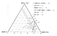
- R410A is a two-component mixed refrigerant of (CH 2 F 2 ; HFC-32 or R32) and pentafluoroethane (C 2 HF 5 ; HFC-125 or R125), and is a pseudo-azeotropic composition.
- R404A is a ternary mixed refrigerant of R125, R134a, and R143a, and is a pseudo-azeotropic composition.
- a single refrigerant, R134a is often used as a refrigerant.
- the global warming potential (GWP) of R410A is 2088
- the global warming potential (GWP) of R404A is 3920
- the global warming potential (GWP) of R134a is 1430.
- refrigerants having a low GWP due to increasing concern about global warming, refrigerants having a low GWP have been used.
- Patent Document 1 proposes a low-GWP mixed refrigerant that can replace R410A.
- Patent Document 2 Japanese Patent Application Laid-Open No. 2018-184597 proposes various low GWP mixed refrigerants that can substitute for R404A.
- Patent Document 3 (WO 2005/105947) proposes a low GWP mixed refrigerant that can be substituted for R134a.
- a refrigeration cycle apparatus capable of improving lubricity in the refrigeration cycle apparatus can be provided.
- the purpose is to provide.
- a refrigeration cycle apparatus includes a refrigerant working fluid including a refrigerant composition including a refrigerant and refrigeration oil.
- the refrigerant is a first refrigerant X, a second refrigerant Y, a third refrigerant A, a fourth refrigerant B, a fifth refrigerant C, a sixth refrigerant D, or a seventh refrigerant E described later. is there.
- the refrigeration cycle apparatus includes a refrigerant having a sufficiently small GWP and refrigerating machine oil, it is possible to improve lubricity in the refrigeration cycle apparatus when performing a refrigeration cycle using the refrigerant composition. It is possible. Further, in this refrigeration cycle, a refrigerant having the same refrigeration capacity as R410A [Refrigeration Capacity (sometimes described as Cooling Capacity or Capacity)] and coefficient of performance [Coefficient of Performance (COP)] is used. It is also possible to improve the lubricity in the refrigeration cycle device when used.
- R410A Refrigeration Capacity (sometimes described as Cooling Capacity or Capacity)]
- coefficient of performance Coefficient of Performance
- a refrigeration cycle apparatus is the refrigeration cycle apparatus according to the first aspect, wherein the kinematic viscosity at 40 ° C. of the refrigerating machine oil is 1 mm 2 / s or more and 750 mm 2 / s or less.
- a refrigeration cycle apparatus is the refrigeration cycle apparatus according to the first aspect or the second aspect of the first group, wherein the kinematic viscosity at 100 ° C. of the refrigeration oil is 1 mm 2 / s or more and 100 mm 2 or more. / S or less.
- a refrigeration cycle apparatus is the refrigeration cycle apparatus according to any one of the first to third aspects of the first group, wherein the refrigeration oil has a volume resistivity at 25 ° C. of 1.0. ⁇ 10 12 ⁇ ⁇ cm or more.
- a refrigeration cycle apparatus is the refrigeration cycle apparatus according to any of the first to fourth aspects of the first group, wherein the acid value of the refrigeration oil is 0.1 mgKOH / g or less. is there.
- the refrigeration cycle apparatus is the refrigeration cycle apparatus according to any one of the first to fifth aspects of the first group, wherein the ash content of the refrigerating machine oil is 100 ppm or less.
- a refrigeration cycle apparatus is the refrigeration cycle apparatus according to any one of the first to sixth aspects of the first group, wherein an aniline point of the refrigeration oil is -100 ° C or more and 0 ° C or less. It is.
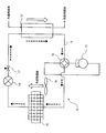
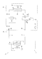
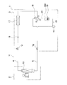
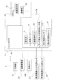
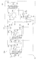
- a refrigeration cycle apparatus is the refrigeration cycle apparatus according to any one of the first to seventh aspects of the first group, including a refrigerant circuit.
- the refrigerant circuit includes a compressor, a condenser, a decompression unit, and an evaporator connected by refrigerant piping.
- the working fluid for the refrigerator circulates inside the refrigerant circuit.
- a refrigeration cycle apparatus is the refrigeration cycle apparatus according to any one of the first to eighth aspects of the first group, wherein a mixing ratio of the refrigerating machine oil in the working fluid for the refrigerating machine is: 5 mass% or more and 60 mass% or less.
- a refrigeration cycle apparatus is the refrigeration cycle apparatus according to any of the first to ninth aspects of the first group, wherein the refrigerating machine oil comprises an acid scavenger, an extreme pressure agent, an antioxidant, It contains at least one additive selected from agents, defoamers, oil agents, metal deactivators, antiwear agents and compatibilizers.
- the ratio of the additive to the mass of the refrigerating machine oil containing the additive is 5% by mass or less.
- the content of the present disclosure has been made in view of the above points, and has a GWP capable of improving lubricity when a refrigeration cycle is performed using a sufficiently small refrigerant, or a refrigerant for a refrigerant or a refrigerant composition. It is an object of the present invention to provide a machine oil, a method for using a refrigerator oil, and use as a refrigerator oil.
- the refrigerating machine oil for a refrigerant composition according to the first aspect of the second group is a refrigerating machine oil for a refrigerant composition containing a refrigerant, and the refrigerant includes “(26) Details of the refrigerant in each of the above groups described below.
- the refrigerant X the refrigerant Y, and the refrigerants A to E.
- the refrigerating machine oil for a refrigerant composition according to the second aspect of the second group is the refrigerating machine oil for a refrigerant composition of the first aspect of the second group, wherein the kinematic viscosity of the refrigerating machine oil at 40 ° C. is 1 mm 2 / s or more and 750 mm 2 / s or less.
- the refrigerating machine oil for the refrigerant composition according to the third aspect of the second group is the refrigerating machine oil for the refrigerant composition of the first or second aspect of the second group, and the kinematic viscosity of the refrigerating machine oil at 100 ° C. , 1 mm 2 / s or more and 100 mm 2 / s or less.
- the refrigerating machine oil for a refrigerant composition according to the fourth aspect of the second group is the refrigerating machine oil for the refrigerant composition of any one of the first to third aspects of the second group, wherein the refrigerating machine oil at 25 ° C.
- the volume resistivity is 1.0 ⁇ 10 12 ⁇ ⁇ cm or more.
- the refrigerating machine oil for a refrigerant composition according to the fifth aspect of the second group is the refrigerating machine oil for the refrigerant composition of any of the first to fourth aspects of the second group, wherein the refrigerating machine oil has an acid value of , 0.1 mgKOH / g or less.
- the refrigerating machine oil for the refrigerant composition according to the sixth aspect of the second group is the refrigerating machine oil for the refrigerant composition of any of the first to fifth aspects of the second group, wherein the ash content of the refrigerating machine oil is: It is 100 ppm or less.
- the refrigerating machine oil for the refrigerant composition according to the seventh aspect of the second group is the refrigerating machine oil for the refrigerant composition of any of the first to sixth aspects of the second group, wherein the aniline point of the refrigerating machine oil is -100 ° C. or higher and 0 ° C. or lower.
- the method for using refrigerating machine oil according to the eighth aspect of the second group is a method for using refrigerating machine oil used with a refrigerant composition containing a refrigerant, wherein the refrigerant includes any of the refrigerants described in (26) below. It is.
- the method for using the refrigerating machine oil according to the ninth aspect of the second group is the method for using the refrigerating machine oil according to the eighth aspect of the second group, wherein the kinematic viscosity at 40 ° C. of the refrigerating machine oil is 1 mm 2 / s or more and 750 mm 2. / S or less.
- the method for using the refrigerating machine oil according to the tenth aspect of the second group is the method for using the refrigerating machine oil according to the eighth or ninth aspect of the second group, wherein the kinematic viscosity at 100 ° C. of the refrigerating machine oil is 1 mm 2 / s or more and 100 mm 2 / s or less.
- the method of using the refrigerating machine oil according to the eleventh aspect of the second group is the method of using the refrigerating machine oil of any of the eighth to tenth aspects of the second group, wherein the volume resistivity of the refrigerating machine oil at 25 ° C. , 1.0 ⁇ 10 12 ⁇ ⁇ cm or more.
- the method for using refrigeration oil according to the twelfth aspect of the second group is the method for using refrigeration oil according to any of the eighth to eleventh aspects of the second group, wherein the acid value of the refrigeration oil is 0.1 mg KOH. / G or less.
- the method of using the refrigerating machine oil according to the thirteenth aspect of the second group is the method of using the refrigerating machine oil of any of the eighth to twelfth aspects of the second group, wherein the ash content of the refrigerating machine oil is 100 ppm or less. .
- a method for using a refrigerating machine oil according to a fourteenth aspect of the second group is the method for using a refrigerating machine oil according to any of the eighth to thirteenth aspects of the second group, wherein the aniline point of the refrigerating machine oil is ⁇ 100 ° C. Not less than 0 ° C.
- the use as a refrigerating machine oil according to the fifteenth aspect of the second group includes the use as a refrigerating machine oil used with a refrigerant composition containing a refrigerant, and the refrigerant includes any of the refrigerants described in (26) below.
- the refrigerating machine oil it is possible to improve lubricity when a refrigeration cycle is performed using a refrigerant having a sufficiently small GWP or a refrigerant composition containing the refrigerant.
- the use as the refrigerating machine oil according to the sixteenth aspect of the second group is the use as the refrigerating machine oil of the fifteenth aspect of the second group, wherein the kinematic viscosity of the refrigerating machine oil at 40 ° C. is 1 mm 2 / s or more and 750 mm 2. / S or less.
- the use of the second group as the refrigerating machine oil according to the seventeenth aspect is the use of the second group as the refrigerating machine oil of the fifteenth or sixteenth aspect, wherein the kinematic viscosity at 100 ° C. of the refrigerating machine oil is 1 mm 2 / s or more and 100 mm 2 / s or less.
- the use of the second group as the refrigerating machine oil according to the eighteenth aspect is the use as the refrigerating machine oil of any of the fifteenth to seventeenth aspects of the second group, wherein the volume resistivity of the refrigerating machine oil at 25 ° C. , 1.0 ⁇ 10 12 ⁇ ⁇ cm or more.
- the use of the second group as a refrigerating machine oil according to the nineteenth aspect is a use as the refrigerating machine oil of any of the fifteenth to eighteenth aspects of the second group, wherein the acid value of the refrigerating machine oil is 0.1 mg KOH. / G or less.
- the use as the refrigerating machine oil according to the twentieth aspect of the second group is the use as the refrigerating machine oil of any of the fifteenth to nineteenth aspects of the second group, and the ash content of the refrigerating machine oil is 100 ppm or less. .
- the use as the refrigerating machine oil according to the twenty-first aspect of the second group is the use as the refrigerating machine oil of any of the fifteenth to twentieth aspects of the second group, wherein the aniline point of the refrigerating machine oil is ⁇ 100 ° C. Not less than 0 ° C.
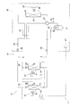
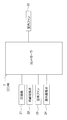
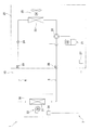
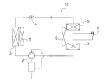
- the refrigeration cycle device includes a refrigerant circuit and a refrigerant.
- the refrigerant circuit has a compressor, a condenser, a decompression unit, and an evaporator.
- the refrigerant is a first refrigerant X, a second refrigerant Y, a third refrigerant A, a fourth refrigerant B, a fifth refrigerant C, a sixth refrigerant D, or a seventh refrigerant E described later. is there.
- This refrigeration cycle apparatus can perform a refrigeration cycle using a refrigerant of a first viewpoint described later in a refrigerant circuit having a compressor, a condenser, a decompression unit, and an evaporator.
- a refrigeration cycle can be performed.
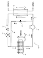
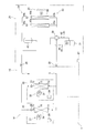
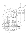
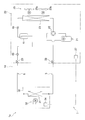
- a refrigeration cycle device is the refrigeration cycle device of the first aspect of the third group, wherein the refrigerant circuit further includes a low-pressure receiver.
- the low-pressure receiver is provided in the middle of the refrigerant flow path from the evaporator to the suction side of the compressor.
- This refrigeration cycle apparatus can perform a refrigeration cycle while storing excess refrigerant in the refrigerant circuit in a low-pressure receiver.
- a refrigeration cycle device is the refrigeration cycle device according to the first aspect or the second aspect of the third group, wherein the refrigerant circuit further includes a high-pressure receiver.
- the high-pressure receiver is provided in the middle of the refrigerant flow path from the condenser to the evaporator.
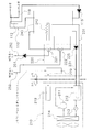
- a refrigeration cycle device is the refrigeration cycle device according to any one of the first to third aspects of the third group, wherein the refrigerant circuit includes a first decompression unit and a second decompression unit. It further has an intermediate pressure receiver.
- the first pressure reducing unit, the second pressure reducing unit, and the intermediate pressure receiver are all provided in the middle of the refrigerant flow path from the condenser to the evaporator.
- the intermediate pressure receiver is provided between the first pressure reducing unit and the second pressure reducing unit in the refrigerant flow path from the condenser to the evaporator.
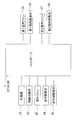
- the refrigeration cycle apparatus is any one of the refrigeration cycle apparatuses of the first to fourth aspects of the third group, and further includes a control unit.
- the refrigerant circuit further has a first pressure reducing unit and a second pressure reducing unit.
- the first decompression unit and the second decompression unit are provided in the middle of the refrigerant flow path from the condenser to the evaporator.
- the control unit adjusts both the degree of pressure reduction of the refrigerant passing through the first pressure reducing unit and the degree of pressure reduction of the refrigerant passing through the second pressure reducing unit.
- the refrigerant flow from the condenser to the evaporator is controlled by controlling the degree of each pressure reduction in the first and second pressure reduction sections provided in the middle of the refrigerant flow path from the condenser to the evaporator. It is possible to reduce the density of the refrigerant located between the first pressure reducing unit and the second pressure reducing unit in the middle of the road. This makes it easier for the refrigerant sealed in the refrigerant circuit to exist in the condenser and / or the evaporator in a large amount, thereby improving the capacity.
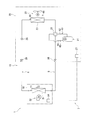
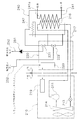
- a refrigeration cycle device is the refrigeration cycle device according to any of the first to fifth aspects of the third group, wherein the refrigerant circuit further includes a refrigerant heat exchange unit. .
- the refrigerant heat exchange unit causes heat exchange between the refrigerant flowing from the condenser to the evaporator and the refrigerant flowing from the evaporator to the compressor.
- the refrigerant flowing from the evaporator to the compressor is heated by the refrigerant flowing from the condenser to the evaporator. For this reason, it is possible to suppress liquid compression in the compressor.
- Fourth group Refrigerants having a small GWP include flammable refrigerants. For this reason, even if the flammable refrigerant leaks, it is preferable to adopt an arrangement structure in which the leaked refrigerant hardly reaches the periphery of the electrical component.
- the content of the present disclosure has been made in view of the above-described points, and is a refrigerant according to a first aspect described below. Even when a flammable refrigerant is used, heat that is difficult for the refrigerant to reach the electrical component unit is obtained. It is intended to provide a replacement unit.
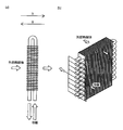
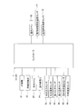
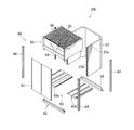
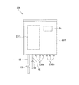
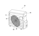
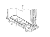
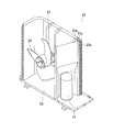
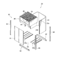
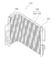
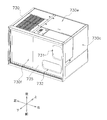
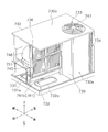
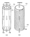
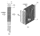
- a heat exchange unit is a heat exchange unit that constitutes a part of a refrigeration cycle device, and includes a housing, a heat exchanger, a pipe connection unit, and an electrical component unit. ing.
- the heat exchange unit is one of a use side unit and a heat source side unit.
- the use side unit and the heat source side unit are connected to each other via a communication pipe.
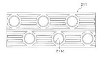
- the heat exchanger is provided in the housing, and the refrigerant flows inside.
- the pipe connection is connected to the communication pipe.
- the electrical component unit is provided in the housing.
- the refrigerant is any of the below-described first to forty-second aspects and is a combustible refrigerant. In the installation state of the heat exchange unit, the lower end of the electrical component unit is arranged at a position higher than the pipe connection.
- the flammable refrigerant means a flammable refrigerant having a flammability class of "2L class" or more in the US ANSI / ASHRAE34-2013 standard.
- the piping connection is not particularly limited, but may be a connection directly or indirectly via another element to the refrigerant piping extending from the heat exchanger.
- the form of the electrical component unit is not particularly limited, and may be an electrical component box containing a plurality of electrical components, or may be a board provided with a plurality of electrical components.
- the present disclosure has been made in view of the above points, and has as its object to provide a refrigeration cycle apparatus that can improve operating efficiency when a refrigerant according to a first aspect described below is used.
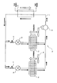
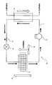
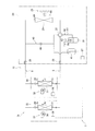
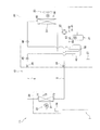
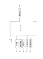
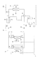
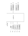
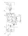
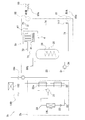
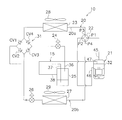
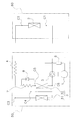
- a refrigeration cycle device includes a compressor, a condenser, a decompression unit, an evaporator, and an injection flow path.
- the compressor draws low-pressure refrigerant from the suction flow path, compresses the refrigerant, and discharges high-pressure refrigerant.
- the condenser condenses the high-pressure refrigerant discharged from the compressor.
- the decompression unit decompresses the high-pressure refrigerant that has exited the condenser.
- the evaporator is decompressed in the decompression unit to evaporate the refrigerant.
- the injection channel is at least one of an intermediate injection channel and a suction injection channel.
- the intermediate injection flow path joins a part of the refrigerant flowing from the condenser to the evaporator with the intermediate pressure refrigerant of the compressor.
- the suction injection flow path joins a part of the refrigerant flowing from the condenser to the evaporator with the low-pressure refrigerant sucked into the compressor.
- the refrigerant is a first refrigerant X, a second refrigerant Y, a third refrigerant A, a fourth refrigerant B, a fifth refrigerant C, a sixth refrigerant D, or a seventh refrigerant E described later. is there.
- a refrigeration cycle device is the refrigeration cycle device according to the first aspect of the fifth group, further comprising a branch flow path, an opening adjustment valve, and an injection heat exchanger.
- the branch passage branches from a main refrigerant passage connecting the condenser and the evaporator.
- the opening adjustment valve is provided in the branch flow path.
- the injection heat exchanger exchanges heat between the refrigerant flowing through the main refrigerant flow path and the refrigerant flowing downstream of the opening adjustment valve of the branch flow path. The refrigerant flowing out of the injection heat exchanger and flowing through the branch flow path flows into the injection flow path.
- a refrigeration cycle apparatus is the refrigeration cycle apparatus according to the first aspect or the second aspect of the fifth group, wherein a refrigerant provided in a main refrigerant flow path connecting a condenser and an evaporator. It also has a storage tank. The gas component of the refrigerant stored inside the refrigerant storage tank flows through the injection flow path.
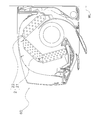
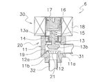
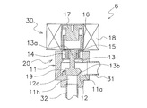
- a refrigeration cycle apparatus is the refrigeration cycle apparatus according to any one of the first to third aspects of the fifth group, wherein the compressor has a fixed scroll and an orbiting scroll. are doing.
- the fixed scroll has a head plate and a wrap that rises spirally from the head plate.
- the orbiting scroll forms a compression chamber by meshing with the fixed scroll. The refrigerant flowing through the injection flow path joins the compression chamber.
- a refrigeration cycle device for a refrigeration cycle device using a refrigerant such as R410A or R32, which has been widely used, a refrigeration cycle device is configured in a case where the existing connection pipe is used and the refrigerant is updated to a first viewpoint refrigerant described later. If the device to be operated performs an operation that exceeds the pressure resistance of the existing connecting pipe, the existing connecting pipe may be damaged.
- the content of the present disclosure has been made in view of the above points, and provides a heat source unit and a refrigeration cycle device capable of suppressing damage to a communication pipe when using a refrigerant according to a first aspect described below. Aim.
- the heat source unit includes a compressor and a heat source side heat exchanger.
- the heat source unit constitutes a refrigeration cycle device by being connected to the utilization unit via a communication pipe. It has a use unit and a use side heat exchanger.
- a refrigerant according to a first aspect described later is used as the refrigerant.
- the design pressure of the heat source unit is lower than 1.5 times the design pressure of the connecting pipe.
- Design pressure means gauge pressure (the same applies hereinafter).
- This heat source unit is operated in a state where the design pressure is lower than the withstand pressure of the communication pipe since the design pressure is lower than 1.5 times the design pressure of the communication pipe. Even if there is, it is possible to suppress damage to the communication pipe.
- a refrigeration cycle apparatus includes a utilization unit, a communication pipe, and a heat source unit according to the first aspect.
- the refrigeration cycle apparatus uses a refrigerant according to a first aspect described below.
- the design pressure of the heat source unit is equivalent to the design pressure in the refrigeration cycle device when the refrigerant R22 or the refrigerant R407C is used.
- ⁇ Equivalent “here is preferably within ⁇ 10% of the design pressure in the refrigeration cycle device when the refrigerant R22 or the refrigerant R407C was used.
- the refrigeration cycle apparatus is the refrigeration cycle apparatus according to the second aspect of the sixth group, wherein the design pressure of the heat source unit is 3.0 MPa or more and 3.7 MPa or less.
- a refrigeration cycle apparatus includes a utilization unit, a communication pipe, and a heat source unit according to the first aspect.
- the refrigeration cycle apparatus uses a refrigerant according to a first aspect described below.
- the design pressure of the heat source unit is equivalent to the design pressure in the refrigeration cycle device when the refrigerant R410A or the refrigerant R32 is used.
- ⁇ Equivalent “here is preferably within ⁇ 10% of the design pressure in the refrigeration cycle device when the refrigerant R410A or the refrigerant R32 was used.
- a refrigeration cycle apparatus is the refrigeration cycle apparatus according to the fourth aspect of the sixth group, wherein the design pressure of the heat source unit is 4.0 MPa or more and 4.8 MPa or less.
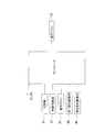
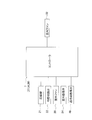
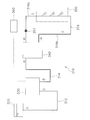
- a refrigeration cycle apparatus includes a heat source unit, a utilization unit, and a communication pipe.
- the heat source unit has a compressor and a heat source side heat exchanger.
- the utilization unit has a utilization side heat exchanger.
- the communication pipe connects the heat source unit and the utilization unit.
- a refrigerant according to a first aspect described below is used.
- the design pressure of the heat source unit is equivalent to the design pressure in the refrigeration cycle device when the refrigerant R22 or the refrigerant R407C is used.
- ⁇ Equivalent “here is preferably within ⁇ 10% of the design pressure in the refrigeration cycle device when the refrigerant R22 or the refrigerant R407C was used.
- a refrigeration cycle apparatus is the refrigeration cycle apparatus according to the sixth aspect of the sixth group, wherein the design pressure of the heat source unit is not less than 3.0 MPa and not more than 3.7 MPa.
- a refrigeration cycle apparatus includes a heat source unit, a utilization unit, and a communication pipe.
- the heat source unit has a compressor and a heat source side heat exchanger.
- the utilization unit has a utilization side heat exchanger.
- the communication pipe connects the heat source unit and the utilization unit.
- a refrigerant according to a first aspect described below is used.
- the design pressure of the heat source unit is equivalent to the design pressure in the refrigeration cycle device when the refrigerant R410A or the refrigerant R32 is used.
- ⁇ Equivalent “here is preferably within ⁇ 10% of the design pressure in the refrigeration cycle device when the refrigerant R410A or the refrigerant R32 was used.
- a refrigeration cycle apparatus is the refrigeration cycle apparatus according to the eighth aspect of the sixth group, wherein the design pressure of the heat source unit is 4.0 MPa or more and 4.8 MPa or less.
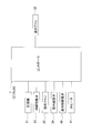
- a heat source unit includes a compressor, a heat source side heat exchanger, and a control device.
- the heat source unit constitutes a refrigeration cycle device by being connected to the utilization unit via a communication pipe.
- the utilization unit has a utilization side heat exchanger.
- a refrigerant according to a first aspect described later is used as the refrigerant.
- the control device is configured so that the upper limit value of the control pressure of the refrigerant can be set or set lower than 1.5 times the design pressure of the communication pipe.
- This heat source unit is configured or set so that the upper limit value of the control pressure of the refrigerant by the control device is lower than 1.5 times the design pressure of the communication pipe. For this reason, even when used by being connected to the communication pipe, operation control in a state lower than the pressure resistance of the communication pipe is ensured, and damage to the communication pipe can be suppressed.
- a refrigeration cycle apparatus includes a utilization unit, a communication pipe, and a heat source unit according to the sixth aspect of the tenth aspect.
- a refrigerant according to a first aspect described below is used.
- the control device is configured so that the upper limit value of the control pressure of the refrigerant can be set or set to be equal to the upper limit value of the control pressure in the refrigeration cycle device when the refrigerant R22 or the refrigerant R407C is used.
- ⁇ Equivalent “here is preferably within ⁇ 10% of the upper limit of the control pressure in the refrigeration cycle apparatus when the refrigerant R22 or the refrigerant R407C is used.
- the upper limit of the control pressure of the refrigerant by the control device of the heat source unit is set to be equal to or equal to the upper limit of the control pressure of the heat source unit of the refrigeration cycle device when the refrigerant R22 or the refrigerant R407C is used. Or since it is comprised so that a setting is possible, it is possible to suppress the damage of a communication pipe.
- a refrigeration cycle apparatus is the refrigeration cycle apparatus according to the eleventh aspect of the sixth group, wherein an upper limit value of the control pressure is set to be 3.0 MPa or more and 3.7 MPa or less.
- a refrigeration cycle apparatus includes a utilization unit, a communication pipe, and a heat source unit according to the tenth aspect.
- a refrigerant according to a first aspect described below is used.
- the control device is configured such that the upper limit value of the control pressure of the refrigerant can be set or set to be equal to the upper limit value of the control pressure in the refrigeration cycle device when the refrigerant R410A or the refrigerant R32 is used.
- ⁇ Equivalent “here is preferably within ⁇ 10% of the upper limit of the control pressure in the refrigeration cycle apparatus when the refrigerant R410A or the refrigerant R32 is used.
- the upper limit of the control pressure of the refrigerant by the control device of the heat source unit is set to be equal to or the same as the upper limit of the control pressure of the heat source unit of the refrigeration cycle device when the refrigerant R410A or the refrigerant R32 is used. Or since it is comprised so that a setting is possible, it is possible to suppress the damage of a communication pipe.
- a refrigeration cycle apparatus is the refrigeration cycle apparatus according to the thirteenth aspect of the sixth group, wherein the upper limit of the control pressure is set to be 4.0 MPa or more and 4.8 MPa or less.
- a refrigeration cycle apparatus includes a heat source unit, a utilization unit, a communication pipe, and a control device.
- the heat source unit has a compressor and a heat source side heat exchanger.
- the utilization unit has a utilization side heat exchanger.
- the communication pipe connects the heat source unit and the utilization unit.
- a refrigerant according to a first aspect described below is used.
- the control device is configured so that the upper limit value of the control pressure of the refrigerant can be set or set to be equal to the upper limit value of the control pressure in the refrigeration cycle device when the refrigerant R22 or the refrigerant R407C is used.
- ⁇ Equivalent “here is preferably within ⁇ 10% of the upper limit of the control pressure in the refrigeration cycle apparatus when the refrigerant R22 or the refrigerant R407C is used.
- the upper limit of the control pressure of the refrigerant by the control device of the heat source unit is set to be equal to or equal to the upper limit of the control pressure of the heat source unit of the refrigeration cycle device when the refrigerant R22 or the refrigerant R407C is used. Or since it is comprised so that a setting is possible, it is possible to suppress the damage of a communication pipe.
- a refrigeration cycle apparatus is the refrigeration cycle apparatus according to the fifteenth aspect of the sixth group, wherein the upper limit of the control pressure is set to 3.0 MPa or more and 3.7 MPa or less.
- a refrigeration cycle apparatus includes a heat source unit, a utilization unit, a communication pipe, and a control device.
- the heat source unit has a compressor and a heat source side heat exchanger.
- the utilization unit has a utilization side heat exchanger.
- the communication pipe connects the heat source unit and the utilization unit.
- the refrigeration cycle apparatus uses a refrigerant according to a first aspect described below.
- the control device is configured such that the upper limit value of the control pressure of the refrigerant can be set or set to be equal to the upper limit value of the control pressure in the refrigeration cycle device when the refrigerant R410A or the refrigerant R32 is used.
- ⁇ Equivalent “here is preferably within ⁇ 10% of the upper limit of the control pressure in the refrigeration cycle apparatus when the refrigerant R410A or the refrigerant R32 is used.
- the upper limit of the control pressure of the refrigerant by the control device of the heat source unit is set to be equal to or the same as the upper limit of the control pressure of the heat source unit of the refrigeration cycle device when the refrigerant R410A or the refrigerant R32 is used. Or since it is comprised so that a setting is possible, it is possible to suppress the damage of a communication pipe.
- a refrigeration cycle apparatus is the refrigeration cycle apparatus according to the seventeenth aspect of the sixth group, wherein an upper limit value of the control pressure is set to be 4.0 MPa or more and 4.8 MPa or less.
- Seventh group Refrigerants having a small GWP include flammable refrigerants.
- an electric heating device having high power consumption may be used for various purposes. As described above, in an air conditioning unit using an electric heating device with high power consumption, it is desired that ignition of the electric heating device be suppressed even if flammable refrigerant may leak.
- the content of the present disclosure has been made in view of the above points, and aims to provide an air conditioning unit that can suppress ignition in an electric heating device even at the time of refrigerant leakage while using a refrigerant with a small GWP. I do.
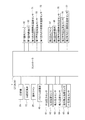
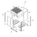
- the air conditioning unit includes a housing, equipment, and an electric heating device.
- the device is provided inside the housing.
- the electric heating device is provided inside the housing.
- the device is a compressor that compresses a refrigerant according to a first aspect described below and / or a heat exchanger that exchanges heat between outside air and a refrigerant according to a first aspect described later.
- the power consumption of the electric heating device is 300 W or less.
- the air conditioning unit is not particularly limited.
- a heat source unit in a refrigeration cycle device such as an air conditioner in which a heat source unit such as an outdoor unit and a use unit such as an indoor unit are connected via a refrigerant communication pipe.
- a heat source unit such as an outdoor unit and a use unit such as an indoor unit are connected via a refrigerant communication pipe.
- the heat source unit may include only the heat exchanger, and the compressor may be provided in another unit.
- a compressor for compressing a first-described refrigerant described below and / or a heat exchanger for exchanging heat between outside air and a first-described refrigerant described later are housed in the housing together with the electric heating device.
- the power consumption of the electric heating device is 300 W or less. Therefore, even if the refrigerant may leak, ignition of the electric heating device is suppressed.
- An air conditioning unit is the air conditioning unit according to the first aspect of the seventh group, wherein the housing has an outlet for blowing air that has passed through the heat exchanger to a side surface in an installed state. Are formed.
- the power consumption of the electric heating device is 75 W or more.
- the power consumption of the electric heating device is 75 W or more, so that the function of the electric heating device is easily exhibited.
- the air conditioning unit according to the third aspect of the seventh group is the air conditioning unit according to the second aspect of the seventh group, and has one fan for forming an airflow passing through the heat exchanger.
- the power consumption of the electric heating device is 75 W or more and 100 W or less.
- the internal volume (volume of fluid that can be filled inside) of the heat exchanger included in the air conditioning unit provided with only one fan is preferably 0.4 L or more and less than 3.5 L.
- the refrigerant circuit in which the air-conditioning unit is used is not provided with a refrigerant container (such as a low-pressure receiver or a high-pressure receiver, excluding the accumulator attached to the compressor), the size should be 0.4 L or more and 2.5 L or less. It is preferable that the refrigerant circuit is provided with a refrigerant container (preferably, a single use unit such as an indoor unit) in the refrigerant circuit.
- this air conditioning unit has such a capacity that only one fan is provided, even if the power consumption of the electric heating device is 100 W or less, the function of the electric heating device is sufficiently exhibited.
- the air conditioning unit according to the fourth aspect of the seventh group is the air conditioning unit according to the second aspect of the seventh group, and includes two fans for forming an airflow passing through the heat exchanger.
- the power consumption of the electric heating device is 100 W or more.
- the internal volume (volume of the fluid that can be filled inside) of the heat exchanger included in the air conditioning unit provided with two fans is 3.5 L or more and 7.0 L or less.
- the use amount is preferably 3.5 L or more and less than 5.0 L.
- the volume is preferably 5.0 L or more and 7.0 L or less.
- this air conditioning unit is provided with two fans, the capacity of the air conditioning unit becomes large, and a large capacity tends to be required as an electric heating device. Since a power of 100 W or more is used, the function of the electric heating device can be sufficiently exhibited by an amount corresponding to the capacity of the air conditioning unit.
- An air conditioning unit is the air conditioning unit according to the first aspect of the seventh group, wherein the housing has an air outlet for blowing air passing through the heat exchanger upward. are doing.
- the power consumption of the electric heating device is 200 W or more.
- the internal volume of the heat exchanger (the volume of the fluid that can be filled therein) of the air-conditioning unit that the air that has passed through the heat exchanger blows upward is 5.5 L or more and 38 L or less.
- the heat exchanger having an inner volume of 5.5 L or more and 38 L or less is preferably adopted in a refrigerant circuit in which a plurality of use units such as an indoor unit having an expansion valve are provided.
- the capacity of the air conditioning unit becomes large, and a large capacity tends to be required also as an electric heating device. Since the power consumption of the electric heating device is 200 W or more, the function of the electric heating device can be sufficiently exhibited by an amount corresponding to the capacity of the air conditioning unit.
- An air conditioning unit is the air conditioning unit according to any of the first to fifth aspects of the seventh group, wherein the electric heating device is at least one of a drain pan heater, a crankcase heater, and a refrigerant heater. Is.
- This air-conditioning unit can suppress freezing of dew condensation water on the drain pan in the air-conditioning unit provided with the drain pan when the drain pan heater is provided.
- an air conditioning unit provided with a compressor it is possible to suppress the generation of foam (oil forming) of refrigerating machine oil at the time of starting the compressor, and to provide a refrigerant in a refrigerant circuit when a refrigerant heater is provided. Can be heated.
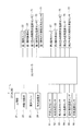
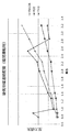
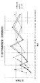
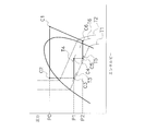
- LCCP Life Cycle climate Performance
- LCCP GWPRM ⁇ W + GWP ⁇ W ⁇ (1-R) + N ⁇ Q ⁇ A
- GWPRM greenhouse related to refrigerant producers
- W refrigerant charge
- R refrigerant recovery amount during equipment disposal
- N equipment usage period (year)
- Q CO 2 emissions intensity
- A annual consumption The amount of power.
- LCCP of the refrigeration cycle device if the filling amount in the refrigerant circuit is too small, the LCCP becomes large due to the deterioration of cycle efficiency due to lack of refrigerant, and further, if the filling amount in the refrigerant circuit is too large, the effect of GWP increases, LCCP grows.
- a refrigerant having a lower GWP than R32 which has been widely used in the past, tends to have a low heat transfer capacity, and tends to have a large LCCP due to a deterioration in cycle efficiency.
- the content of the present disclosure has been made in view of the above points, and in the case where a heat cycle is performed using a refrigerant having a sufficiently small GWP, a refrigerant cycle device capable of keeping LCCP low and refrigerant charging in the refrigerant cycle device. It is intended to provide a method for determining the amount.
- the refrigeration cycle apparatus includes a heat source unit, a utilization unit, and a refrigerant pipe.
- the heat source unit has a compressor and a heat source side heat exchanger.
- the utilization unit has a utilization side heat exchanger.
- the refrigerant pipe connects the heat source unit and the utilization unit.
- a refrigerant circuit configured by connecting the compressor, the heat source side heat exchanger, and the use side heat exchanger is filled with a refrigerant according to a first aspect described below.
- the amount of refrigerant charged in the refrigerant circuit satisfies the condition of 160 g or more and 560 g or less per 1 kW of refrigeration capacity of the refrigeration cycle device.
- the refrigeration capacity of the refrigeration cycle device means the rated refrigeration capacity.
- This refrigeration cycle device in the refrigerant circuit, since the refrigerant of the first viewpoint described below is enclosed in 160 g or more and 560 g or less per 1 kW of refrigeration capacity, when the GWP performs a heat cycle using a sufficiently small refrigerant, LCCP can be kept low.
- the internal volume of the heat-source-side heat exchanger (the volume of the fluid that can be filled inside) is provided by a refrigerant container (such as a low-pressure receiver or a high-pressure receiver, excluding the accumulator attached to the compressor) in the refrigerant circuit.
- a refrigerant container such as a low-pressure receiver or a high-pressure receiver, excluding the accumulator attached to the compressor
- Those not provided are preferably 0.4 L or more and 2.5 L or less, and those provided with a refrigerant container in the refrigerant circuit are preferably 1.4 L or more and less than 5.0 L.
- the internal volume (volume of fluid that can be filled in) of the heat source side heat exchanger included in the heat source unit provided with only one fan includes air passing through the heat source side heat exchanger on the side surface in the installed state.
- the heat source unit has a housing in which an air outlet for blowing air is formed (when the heat source unit is a trunk type or the like)
- it is preferably 0.4 L or more and less than 3.5 L.
- the volume of the heat source side heat exchanger (the volume of the fluid that can be filled inside) of the heat source side heat exchanger included in the heat source unit provided with two is provided for blowing air that has passed through the heat source side heat exchanger to the side surface in the installed state.
- the length is preferably 3.5 L or more and less than 5.0 L.
- a refrigeration cycle apparatus includes a heat source unit, a first usage unit, a second usage unit, and a refrigerant pipe.
- the heat source unit has a compressor and a heat source side heat exchanger.
- the first usage unit has a first usage-side heat exchanger.
- the second usage unit has a second usage-side heat exchanger.
- the refrigerant pipe connects the heat source unit, the first usage unit, and the second usage unit.
- a refrigerant of a first viewpoint described later is sealed. I have.
- the amount of refrigerant per 1 kW of refrigeration capacity of the refrigerant circuit satisfies the condition of 190 g to 1660 g.
- a refrigerant of a first viewpoint described later is sealed in a range of 190 g or more and 1660 g or less per 1 kW of refrigeration capacity.
- the first usage unit does not have an expansion valve on the liquid side of the first usage side heat exchanger
- the volume is preferably 1.4 L or more and less than 5.0 L
- the first usage unit has the first usage-side heat exchanger.
- the pressure is preferably 5.0 L or more and 38 L or less.
- the internal volume (volume of fluid that can be filled in) of the heat source side heat exchanger included in the heat source unit provided with only one fan includes air passing through the heat source side heat exchanger on the side surface in the installed state.
- the heat source unit has a housing in which an air outlet for blowing air is formed (when the heat source unit is a trunk type or the like)
- it is preferably 0.4 L or more and less than 3.5 L.
- the volume of the heat source side heat exchanger (the volume of the fluid that can be filled inside) of the heat source side heat exchanger included in the heat source unit provided with two is provided for blowing air that has passed through the heat source side heat exchanger to the side surface in the installed state.
- the heat source unit When the heat source unit has a housing in which the air outlet is formed (when the heat source unit is a trunk type or the like), it is preferably 3.5 L or more and 7.0 L or less. As the internal volume of the heat source-side heat exchanger air passing through the exchanger has the heat source unit for blowing upward (the volume of fluid that can be filled in) is preferably less than 5.5 L 38L.
- the content of the present disclosure has been made in view of the above points, and has as its object to provide a refrigeration cycle device capable of suppressing a decrease in capacity when a refrigerant according to a first aspect described below is used.
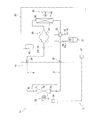
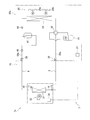
- the refrigeration cycle apparatus includes a refrigerant circuit to which a compressor, a heat source side heat exchanger, a pressure reducing unit, a liquid side refrigerant communication pipe, a use side heat exchanger, and a gas side refrigerant communication pipe are connected. Have.
- the refrigeration cycle apparatus uses a refrigerant according to a first aspect described below.
- the pressure reducing section is not particularly limited, and may be an expansion valve or a capillary tube.
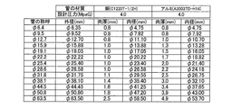
- the range of D 0 is “2 ⁇ D 0 ⁇ 3”, and in the gas-side refrigerant communication pipe, the range of D 0 is “4 ⁇ D 0 ⁇ 7”. preferable.
- the use of the refrigerant of the first aspect described below makes it possible to keep the GWP sufficiently small and to keep the decrease in capacity small.
- the refrigeration cycle device may be the following refrigeration cycle device based on the difference in physical properties between the refrigerant of the present disclosure and the refrigerant R32.
- rated refrigerating capacity of the refrigeration cycle apparatus is less 10.0kW than 6.3KW, and, the outer diameter of the liquid side refrigerant communication pipe D 0/8 inches (Where “D 0 ⁇ -1 inch” is the outer diameter of the liquid-side refrigerant communication pipe when the refrigerant R32 is used), and the liquid-side refrigerant communication pipe has D 0 of 3 There may be.
- rated refrigerating capacity of the refrigeration cycle device is not more than 4.0 kW
- the outer diameter of the gas-side refrigerant communication pipe D 0/8 inches (here, “D 0 ⁇ / inch” is the outer diameter of the gas-side refrigerant communication pipe when the refrigerant R32 is used)
- the gas-side refrigerant communication pipe may have a D 0 of 4.
- rated refrigerating capacity of the refrigeration cycle apparatus is less 10.0kW than 6.3KW, and, outer diameter of the gas-side refrigerant communication pipe D 0/8 inches (Where “D 0 ⁇ inch” is the outer diameter of the gas-side refrigerant communication pipe when the refrigerant R32 is used), and the gas-side refrigerant communication pipe has D 0 of 5 There may be.
- rated refrigerating capacity of the refrigeration cycle apparatus is less 19.0kW above 15.0KW, and, outer diameter of the gas-side refrigerant communication pipe D 0/8 inches (where "D 0 -1/8 inch” is the outer diameter of the gas-side refrigerant communication pipe when the coolant R32 is used), and and the gas-side refrigerant communication pipe is D 0 6 There may be.
- rated refrigerating capacity of the refrigeration cycle apparatus is not less than 25.0KW, and, the outer diameter of the gas-side refrigerant communication pipe D 0/8 inches (here, “D 0 ⁇ / inch” is the outer diameter of the gas-side refrigerant communication pipe when the refrigerant R32 is used), and the gas-side refrigerant communication pipe may have a D 0 of 7. .
- a refrigeration cycle apparatus is the refrigeration cycle apparatus according to the first aspect of the ninth group, wherein the rated refrigeration capacity of the refrigeration cycle apparatus is greater than 5.6 kW and less than 11.2 kW, and , the liquid-side refrigerant communication pipe D 0 is 3 (i.e. a pipe diameter of 3/8 inch).
- the rated cooling capacity of the refrigeration cycle apparatus is less 10.0kW than 6.3KW, and, the liquid-side refrigerant communication pipe is preferably D 0 is 3 (i.e. a pipe diameter of 3/8 inch).
- a refrigeration cycle device is the refrigeration cycle device according to the first aspect of the ninth group, wherein the refrigeration cycle device has a rated refrigeration capacity of greater than 22.4 kW and the gas-side refrigerant communication pipe is D 0 is 7 (that is, the pipe diameter is 7/8 inch), or the rated refrigerating capacity of the refrigeration cycle apparatus is more than 14.0 kW and less than 22.4 kW, and the gas-side refrigerant communication pipe has D 0 of 6 (that is, or diameter of 6/8 inch), D 0 is and gas refrigerant communication pipe rated cooling capacity is less than greater than 5.6 kW 11.2KW refrigeration cycle device 5 (i.e., the pipe diameter is 5/8 inches ) it is either, and the gas-side refrigerant communication pipe is less than 4.5kW rated refrigerating capacity of the refrigeration cycle apparatus or D 0 is 4 (i.e., the pipe diameter of 1/2 inch), is either.
- the refrigeration cycle device has a rated refrigeration capacity of greater than 22.4 kW and the gas-side refrig
- the rated refrigerating capacity of the refrigerating cycle device is 25.0 kW or more
- the gas side refrigerant communication pipe has D 0 of 7 (that is, the pipe diameter is 7/8 inch), or the refrigerating cycle device has a rated refrigerating capacity of Is not less than 15.0 kW and less than 19.0 kW
- the gas side refrigerant communication pipe has D 0 of 6 (that is, the pipe diameter is 6/8 inch) or the refrigeration cycle apparatus has a rated refrigeration capacity of 6.3 kW or more.
- gas-side refrigerant communication pipe has D 0 of 5 (that is, the pipe diameter is / inch), or the refrigeration cycle apparatus has a rated refrigeration capacity of less than 4.0 kW, and it is preferred gas-side refrigerant communication pipe is either D 0 is 4 (i.e., the pipe diameter of 1/2 inch), is either.
- a refrigeration cycle apparatus includes a refrigerant circuit to which a compressor, a heat source side heat exchanger, a pressure reducing unit, a liquid side refrigerant communication pipe, a use side heat exchanger, and a gas side refrigerant communication pipe are connected.
- the cycle device uses a refrigerant according to a first aspect described below.
- the outer diameter of the liquid-side refrigerant communication pipe is the same as the outer diameter of the liquid-side refrigerant communication pipe when the refrigerant R410A is used, and the refrigerant R410A is used as the outer diameter of the gas-side refrigerant communication pipe. It is the same as the outer diameter of the gas-side refrigerant communication pipe in the case.
- the pressure reducing section is not particularly limited, and may be an expansion valve or a capillary tube.
- the range of D 0 is “2 ⁇ D 0 ⁇ 3”, and in the gas-side refrigerant communication pipe, the range of D 0 is “4 ⁇ D 0 ⁇ 7”. preferable.
- a refrigerant including a refrigerant allows the GWP to be kept sufficiently small and a decrease in capacity to be kept small.
- Refrigeration cycle apparatus according to a fifth aspect of the ninth group, a fourth aspect of the refrigeration cycle apparatus of the ninth group, the liquid-side refrigerant communication pipe, D 0 is 2 (i.e. 1/4 inch pipe diameter) It is.
- a refrigeration cycle apparatus is the refrigeration cycle apparatus according to the fourth aspect of the ninth group, wherein the refrigeration cycle apparatus has a rated refrigeration capacity of 6.3 kW or more and a liquid-side refrigerant connection.
- piping or D 0 is 3 (i.e. a pipe diameter of 3/8 inch), or, rated refrigerating capacity of the refrigeration cycle apparatus is less than 6.3KW, and the liquid-side refrigerant communication pipe D 0 2 ( That is, the pipe diameter is 1/4 inch).
- a refrigeration cycle apparatus is the refrigeration cycle apparatus according to the fourth aspect of the ninth group, wherein the refrigeration cycle apparatus has a rated refrigeration capacity of 6.0 kW or more, and has a gas-side refrigerant connection. or piping D 0 is 4 (i.e., the pipe diameter of 1/2 inch), or, rated refrigerating capacity of the refrigeration cycle apparatus is less than 6.0 kW, and the gas-side refrigerant communication pipe D 0 is 3 ( That is, the pipe diameter is 3/8 inch).
- a refrigeration cycle apparatus is the refrigeration cycle apparatus according to the fourth aspect of the ninth group, wherein the refrigeration cycle apparatus has a rated refrigeration capacity of 25.0 kW or more, and has a gas-side refrigerant connection. or piping is D 0 7 (i.e. pipe diameter is 7/8 inches), the rated cooling capacity of the refrigeration cycle apparatus is less than 15.0kW 25.0kW, and the gas-side refrigerant communication pipe is D 0 6 (that is, the pipe diameter is 6/8 inch), or the rated refrigerating capacity of the refrigeration cycle device is 6.3 kW or more and less than 15.0 kW, and the gas-side refrigerant communication pipe has D 0 of 5 (that is, the pipe diameter).
- the rated cooling capacity of the refrigeration cycle apparatus is less than 6.3KW, and, if the gas-side refrigerant communication pipe is D 0 is 4 (i.e., the pipe diameter of 1/2 inch) , Either.
- a refrigeration cycle apparatus includes a refrigerant circuit to which a compressor, a heat source side heat exchanger, a pressure reducing unit, a liquid side refrigerant communication pipe, a use side heat exchanger, and a gas side refrigerant communication pipe are connected.
- the refrigeration cycle apparatus uses a refrigerant according to a first aspect described below.
- the pressure reducing section is not particularly limited, and may be an expansion valve or a capillary tube.
- the range of D 0 is “2 ⁇ D 0 ⁇ 3”, and in the gas-side refrigerant communication pipe, the range of D 0 is “4 ⁇ D 0 ⁇ 7”. preferable.
- the use of the refrigerant of the first aspect described below makes it possible to keep the GWP sufficiently small and to keep the decrease in capacity small.
- Refrigeration cycle apparatus is the refrigeration cycle apparatus of the ninth aspect of the ninth group, the liquid-side refrigerant communication pipe, D 0 is 2 (i.e. 1/4 inch pipe diameter) It is.
- a refrigeration cycle device is the refrigeration cycle device according to the ninth aspect of the ninth group, wherein the refrigeration cycle device has a rated refrigeration capacity of 7.5 kW or more, and has a liquid-side refrigerant connection.
- D 0 is 2.5 (i.e., the pipe diameter of 5/16 inch)
- the rated cooling capacity of the refrigeration cycle apparatus is less than 2.6 kW 7.5 kW
- the liquid-side refrigerant communication pipe D 0 is 2 (that is, the pipe diameter is 1/4 inch)
- the rated refrigerating capacity of the refrigeration cycle apparatus is less than 2.6 kW
- the liquid-side refrigerant communication pipe has a D 0 of 1.5 (that is, the pipe diameter). Is 3/16 inch).
- a refrigeration cycle apparatus is the refrigeration cycle apparatus according to the ninth aspect of the ninth group, wherein the refrigeration cycle apparatus has a rated refrigeration capacity of 6.3 kW or more, and has a liquid-side refrigerant connection.
- piping or D 0 is 3 (i.e. a pipe diameter of 3/8 inch), or, rated refrigerating capacity of the refrigeration cycle apparatus is less than 6.3KW, and the liquid-side refrigerant communication pipe D 0 2 ( That is, the pipe diameter is 1/4 inch).
- a refrigeration cycle apparatus is the refrigeration cycle apparatus according to the ninth group of the ninth aspect, wherein the refrigeration cycle apparatus has a rated refrigeration capacity of 12.5 kW or more, and has a liquid-side refrigerant connection.
- the pipe has D 0 of 3 (that is, the pipe diameter is 3/8 inch), or the rated refrigerating capacity of the refrigeration cycle apparatus is 6.3 kW or more and less than 12.5 kW, and the liquid-side refrigerant communication pipe has a D 0.
- the pipe diameter of 5/16 inch or a rated cooling capacity of the refrigeration cycle apparatus is less than 6.3KW, and the liquid-side refrigerant communication pipe D 0 is 2 (i.e., the pipe diameter is 1 / 4 inch).
- a refrigeration cycle device is the refrigeration cycle device according to the ninth group of the ninth aspect, wherein the refrigeration cycle device has a rated refrigeration capacity of 6.0 kW or more, and has a gas-side refrigerant connection. or piping D 0 is 4 (i.e., the pipe diameter of 1/2 inch), or, rated refrigerating capacity of the refrigeration cycle apparatus is less than 6.0 kW, and the gas-side refrigerant communication pipe D 0 is 3 ( That is, the pipe diameter is 3/8 inch).
- a refrigeration cycle apparatus is the refrigeration cycle apparatus according to the ninth group, wherein the refrigeration cycle apparatus has a rated refrigeration capacity of 6.0 kW or more and a gas-side refrigerant connection. or piping is D 0 is 4 (i.e., the pipe diameter of 1/2 inch), the rated cooling capacity of the refrigeration cycle apparatus is less than 3.2 kW 6.0 kW, and the gas-side refrigerant communication pipe is D 0 3 (i.e., the pipe diameter of 3/8 inch) or a rated cooling capacity of the refrigeration cycle apparatus is less than 3.2 kW, and the gas-side refrigerant communication pipe is D 0 2.5 (i.e. pipe diameter of 5 / 16 inch).
- a refrigeration cycle device is the refrigeration cycle device according to the ninth group of the ninth aspect, wherein the refrigeration cycle device has a rated refrigeration capacity of 25.0 kW or more, and has a gas-side refrigerant connection. or piping is D 0 7 (i.e. pipe diameter is 7/8 inches), the rated cooling capacity of the refrigeration cycle apparatus is less than 15.0kW 25.0kW, and the gas-side refrigerant communication pipe is D 0 6 (that is, the pipe diameter is 6/8 inch), or the rated refrigerating capacity of the refrigeration cycle device is 6.3 kW or more and less than 15.0 kW, and the gas-side refrigerant communication pipe has D 0 of 5 (that is, the pipe diameter).
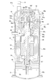
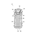
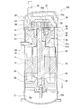
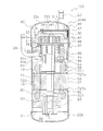
- a compressor according to a first aspect of the tenth group includes a compression unit and a motor.
- the compressor compresses a refrigerant according to any of the first to forty-second aspects described below.
- the motor has a rotor including a permanent magnet and drives a compression unit.
- the compressor is suitable for a variable displacement compressor that can change the number of rotations of the motor because the motor has a rotor that includes a permanent magnet.
- the motor speed can be changed according to the air conditioning load, so that the efficiency of the compressor can be increased.
- a compressor according to a second aspect of the tenth group is the compressor according to the first aspect of the tenth group, wherein the rotor is an embedded magnet type rotor.
- the embedded magnet type rotor a permanent magnet is embedded in the rotor.
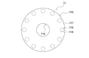
- a compressor according to a third aspect of the tenth group is the compressor according to the first aspect or the second aspect of the tenth group, wherein the rotor is formed by stacking a plurality of electromagnetic steel sheets in a thickness direction. .
- the thickness of the electromagnetic steel sheet is 0.05 mm or more and 0.5 mm or less.
- the eddy current loss can be reduced by reducing the thickness of the sheet.
- the thickness is less than 0.05 mm, it is difficult to process the electromagnetic steel sheet.
- the thickness is desirably 0.05 to 0.5 mm.
- a compressor according to a fourth aspect of the tenth group is the compressor according to the first aspect or the second aspect of the tenth group, wherein the rotor is formed by stacking a plurality of plate-shaped amorphous metals in a plate thickness direction. Have been.
- the compressor according to a fifth aspect of the tenth group is the compressor according to the first aspect or the second aspect of the tenth group, wherein the rotor has a thickness of a plurality of electromagnetic steel sheets containing 5% by mass or more of silicon. It is formed by laminating in the direction.
- a compressor according to a sixth aspect of the tenth group is the compressor according to any one of the first to fifth aspects of the tenth group, wherein the permanent magnet is an Nd—Fe—B-based magnet.
- the compressor according to the seventh aspect of the tenth group is the compressor according to any one of the first to sixth aspects of the tenth group, wherein the permanent magnet is formed by grain boundary diffusion of heavy rare earth elements.
- the demagnetization proof strength of the permanent magnet is improved, and the holding power of the permanent magnet can be increased with a small amount of heavy rare earth elements, so that the compressor can be made more efficient.
- a compressor according to an eighth aspect of the tenth group is the compressor according to the sixth aspect of the tenth group, wherein the permanent magnet contains 1% by mass or less of dysprosium.
- the compressor according to the ninth aspect of the tenth group is the compressor according to any one of the first to eighth aspects of the tenth group, wherein the permanent magnet has an average crystal grain size of 10 ⁇ m or less.
- the demagnetization resistance of the permanent magnet is increased, so that the compressor can be made more efficient.
- a compressor according to a tenth group according to a tenth aspect is the compressor according to the first aspect or the second aspect of the tenth group, wherein the permanent magnets are plate-shaped, and the plurality of permanent magnets form a V shape. Embedded in the rotor. The holding force of the portion located in the V-shaped valley is set higher than the other portions by ⁇ 1 / (4 ⁇ ) ⁇ ⁇ 10 3 [A / m] or more.
- a compressor according to an eleventh aspect of the tenth group is the compressor according to the first aspect or the second aspect of the tenth group, wherein the rotor is formed by rolling a plurality of high-tensile electrical steel sheets having a tensile strength of 400 MPa or more. It is formed by laminating in the thickness direction.
- a compressor according to a twelfth aspect of the tenth group is the compressor according to the eleventh aspect of the tenth group, in which the permanent magnets form a flat plate having a predetermined thickness.
- the rotor has a receiving hole, a non-magnetic space, and a bridge.
- a plurality of permanent magnets are embedded in the receiving hole.
- the non-magnetic space extends from the end of each of the permanent magnets housed in the housing hole to near the surface of the rotor.
- the bridge is located outside the nonmagnetic space and connects the magnetic poles.
- the thickness of the bridge is 3 mm or more.
- a compressor according to a thirteenth aspect of the tenth group is the compressor according to the first aspect of the tenth group, wherein the rotor is a surface magnet type rotor.
- the surface magnet type rotor has a permanent magnet attached to the surface of the rotor.
- a refrigeration cycle apparatus is a refrigeration cycle apparatus including any one of the compressors according to the first to thirteenth aspects of the tenth group.
- a heat transfer tube included in a heat exchanger is used as a refrigeration cycle apparatus using R32 as a refrigerant. It has been proposed that the pipe diameter be 7 mm or more and 10 mm or less.
- the pipe diameter of the heat transfer tube of the heat exchanger that can reduce the amount of the retained refrigerant while reducing the pressure loss. Has not been considered at all.
- a refrigeration cycle apparatus capable of reducing the amount of refrigerant retained while reducing pressure loss. The purpose is to provide.
- a refrigeration cycle device includes a refrigerant circuit and a refrigerant.
- the refrigerant circuit has a compressor, a heat source side heat exchanger, a pressure reducing unit, and a use side heat exchanger.
- the refrigerant is sealed in the refrigerant circuit, and is a refrigerant according to a first aspect described later.
- the heat source side heat exchanger includes a heat transfer tube having a pipe diameter of 6.35 mm or more and less than 10.0 mm.
- the pressure reducing section is not particularly limited, and may be an expansion valve or a capillary tube.
- This refrigeration cycle apparatus can suppress the GWP sufficiently by using the refrigerant of the first aspect described later, reduce the pressure loss, and reduce the amount of the refrigerant retained.
- a refrigeration cycle apparatus is the refrigeration cycle apparatus according to the first aspect of the eleventh group, wherein the heat source side heat exchanger has a pipe diameter of 6.35 mm, 7.0 mm, and 8.0 mm. And 9.5 mm.
- a refrigeration cycle apparatus is the refrigeration cycle apparatus according to the first aspect or the second aspect of the eleventh group, wherein the heat source-side heat exchanger has a pipe diameter of 7.0 mm or more. Has a heat tube.
- a refrigeration cycle device includes a refrigerant circuit and a refrigerant.
- the refrigerant circuit has a compressor, a heat source side heat exchanger, a pressure reducing unit, and a use side heat exchanger.
- the refrigerant is sealed in the refrigerant circuit, and is a refrigerant according to a first aspect described later.
- the use side heat exchanger has a heat transfer tube having a pipe diameter of 4.0 mm or more and less than 10.0 mm.
- This refrigeration cycle apparatus can suppress the GWP sufficiently by using the refrigerant of the first aspect described later, reduce the pressure loss, and reduce the amount of the refrigerant retained.
- a refrigeration cycle apparatus is the refrigeration cycle apparatus according to the fourth aspect of the eleventh group, wherein the use-side heat exchanger includes a heat transfer tube having a pipe diameter of 8.0 mm or less. ing.
- a refrigeration cycle apparatus is the refrigeration cycle apparatus according to the fourth or fifth aspect of the eleventh group, wherein the use-side heat exchanger has a pipe diameter of 4.0 mm and 5.0 mm. And 6.35 mm, 7.0 mm, and 8.0 mm.
- a compressor according to a first aspect of the twelfth group includes a compressor for compressing a refrigerant according to any of the first to forty-second aspects described below, and an induction motor for driving the compressor.
- the compressor according to a second aspect of the twelfth group is the compressor according to the first aspect of the twelfth group, wherein the rotor of the induction motor is a rod-shaped conductor and a plurality of conductor rods arranged in a ring. And an end ring that short-circuits the plurality of conductor rods at the ends in the axial direction. At least the conductor bar is formed of a metal having lower electric resistance than aluminum.
- the compressor according to the third aspect of the twelfth group is the compressor according to the first aspect of the twelfth group, wherein the rotor of the induction motor has a heat dissipation structure.
- the compressor according to a fourth aspect of the twelfth group is the compressor according to the third aspect of the twelfth group, wherein the rotor of the induction motor is a rod-shaped conductor and a plurality of conductor rods arranged in a ring. And an end ring that short-circuits the plurality of conductor rods at the ends in the axial direction.
- the heat dissipation structure is formed in an end ring.
- the compressor according to the fifth aspect of the twelfth group is the compressor according to the third or fourth aspect of the twelfth group, wherein the heat dissipation structure is a heat sink.
- the heat sink can be integrally formed when forming the end ring of the induction motor, and it is possible to increase the output at a relatively low cost.
- the compressor according to the sixth aspect of the twelfth group is the compressor according to the first aspect of the twelfth group, further comprising a cooling structure for cooling a stator of the induction motor with a refrigerant.
- the induction motor is cooled, so that high output can be achieved.
- a compressor according to a seventh aspect of the twelfth group is the compressor according to the sixth aspect of the twelfth group, wherein the cooling structure cools the stator by cold heat of a refrigerant flowing in a refrigerant circuit to which the compressor is connected. .
- a refrigeration cycle apparatus is a refrigeration cycle apparatus including any one of the compressors according to the first to seventh aspects of the twelfth group.
- the air conditioner according to the first aspect of the thirteenth group includes a compressor for compressing a refrigerant according to any one of the first to forty-second aspects described below, and a power converter.
- the power converter is connected between a motor that drives the compressor, an AC power supply and the motor, has a switching element, and controls the switching element so that the output of the motor becomes a target value.
- the motor rotation speed of the compressor can be changed in accordance with the air conditioning load, so that high year-round energy consumption efficiency [Annual Performance Factor ( APF)].
- the air conditioner according to the second aspect of the thirteenth group is the air conditioner of the first aspect of the thirteenth group, wherein the power converter includes a rectifier circuit and a capacitor.
- the rectifier circuit rectifies the AC voltage of the AC power supply.
- the capacitor is connected in parallel to the output side of the rectifier circuit, and smoothes voltage fluctuations caused by switching of the power converter.
- the air conditioner according to the third aspect of the thirteenth group is the air conditioner according to the first aspect or the second aspect of the thirteenth group, wherein the AC power supply is a single-phase power supply.
- the air conditioner according to the fourth aspect of the thirteenth group is the air conditioner according to the first aspect or the second aspect of the thirteenth group, wherein the AC power supply is a three-phase power supply.
- the air conditioner according to the fifth aspect of the thirteenth group is the air conditioner according to the first aspect of the thirteenth group, wherein the power converter is an indirect matrix converter including a converter and an inverter.
- the converter converts an AC voltage of the AC power supply into a DC voltage.
- the inverter converts a DC voltage into an AC voltage and supplies the AC voltage to the motor.
- This air conditioner is highly efficient and does not require an electrolytic capacitor on the output side of the rectifier circuit, so that the circuit size and cost are suppressed.
- An air conditioner according to a sixth aspect of the thirteenth group is the air conditioner according to the first aspect of the thirteenth group, wherein the power converter directly converts the AC voltage of the AC power supply into an AC voltage of a predetermined frequency to the motor. Supplying a matrix converter.
- This air conditioner is highly efficient and does not require an electrolytic capacitor on the output side of the rectifier circuit, so that the circuit size and cost are suppressed.
- the air conditioner according to a seventh aspect of the thirteenth group is the air conditioner according to the first aspect of the thirteenth group, wherein the compressor is any one of a scroll compressor, a rotary compressor, a turbo compressor, and a screw compressor. It is.
- An air conditioner according to an eighth aspect of the thirteenth group is the air conditioner according to any one of the first to seventh aspects of the thirteenth group, wherein the motor is a permanent magnet synchronous motor having a rotor including a permanent magnet. is there.
- a refrigerant having a low global warming potential (GWP) (hereinafter, referred to as a low GWP refrigerant) has been studied as a refrigerant used in an air conditioner.
- GWP refrigerant a refrigerant according to a first aspect described below is effective.
- An air conditioner includes a compressor for compressing a refrigerant according to any of the first to forty-second aspects described below, a motor for driving the compressor, and frequency conversion from an AC power supply to a motor. And a connecting portion for supplying power without causing the power to be supplied.
- the compressor can be driven without interposing a power converter between the AC power supply and the motor, so that the cost is relatively low. With such a configuration, it is possible to provide an air conditioner in consideration of environmental protection.
- the air conditioner according to the second aspect of the fourteenth group is the air conditioner according to the first aspect of the fourteenth group, wherein the connection section directly applies an AC voltage of an AC power supply between at least two terminals of the motor.
- the air conditioner according to the third aspect of the fourteenth group is the air conditioner according to the first aspect or the second aspect of the fourteenth group, wherein the AC power supply is a single-phase power supply.
- the air conditioner according to the fourth aspect of the fourteenth group is the air conditioner according to any one of the first to third aspects of the fourteenth group, wherein a starting circuit is connected in series to one terminal of the motor.
- the air conditioner according to the fifth aspect of the fourteenth group is the air conditioner of the fourth aspect of the fourteenth group, wherein the starting circuit is a circuit in which a positive temperature coefficient thermistor and an operating capacitor are connected in parallel.
- the positive temperature coefficient thermistor self-heats and its resistance value increases, and the operation proceeds to an operation circuit substantially using an operation capacitor. Since the switching is performed, the compressor is in a state capable of outputting the rated torque in a timely manner.
- the air conditioner according to the sixth aspect of the fourteenth group is the air conditioner of the first aspect or the second aspect of the fourteenth group, wherein the AC power supply is a three-phase power supply.
- This air conditioner is relatively inexpensive because it does not require a startup circuit.
- the air conditioner according to the seventh aspect of the fourteenth group is the air conditioner according to any one of the first to sixth aspects of the fourteenth group, wherein the motor is an induction motor.
- the motor can output high power at a relatively low cost, so that the efficiency of the air conditioner can be increased.
- a conventional hot water production apparatus employing a heat pump unit often uses carbon dioxide as a refrigerant in the heat pump unit.
- carbon dioxide as a refrigerant in the heat pump unit.
- the hot water manufacturing apparatus uses the below-described first aspect refrigerant as the refrigerant.
- This hot water production device includes a compressor, a first heat exchanger on a heat source side, an expansion mechanism, and a second heat exchanger on a use side.
- the second heat exchanger heats the first water by exchanging heat between the mixed refrigerant flowing therein and the first water.
- the above-mentioned mixed refrigerant is used as a refrigerant, instead of carbon dioxide which has been conventionally used frequently. This enables efficient production of hot water.
- a hot water production device is the hot water production device according to the first aspect of the fifteenth group, further comprising a tank and a circulation channel.
- the circulation channel circulates the first water between the tank and the second heat exchanger.
- the hot water production apparatus is the hot water production apparatus according to the first aspect of the fifteenth group, wherein the first circulation flow path, the second circulation flow path, the third heat exchanger, And a tank.
- the first circulation channel circulates the first water heated by the second heat exchanger.
- the second circulation channel is a circulation channel different from the first circulation channel.
- the third heat exchanger causes heat exchange between the first water flowing through the first circulation flow path and the second water flowing through the second circulation flow path, and causes the second heat flow through the second circulation flow path. Heat the water.
- the tank stores the second water heated by the third heat exchanger.
- a hot water production device is the hot water production device according to the first aspect of the fifteenth group, further comprising a first circulation channel and a tank.
- the first circulation channel circulates the first water heated by the second heat exchanger.
- a part of the first circulation channel is disposed in the tank, and heat is exchanged between the first water flowing in the first circulation channel and the second water in the tank. Heat the second water in the tank.
- the hot water producing apparatus is the hot water producing apparatus according to the first aspect of the fifteenth group, wherein the tank, the first circulation flow path, the third heat exchanger, and the second circulation flow And a third flow path.
- the first circulation channel circulates the first water between the second heat exchanger and the tank.
- the second circulation channel circulates the first water between the third heat exchanger and the tank.
- the third flow path is a different flow path from the first circulation flow path and the second circulation flow path.
- the third heat exchanger heats the third water flowing through the third flow path by causing heat exchange between the first water flowing from the tank and the third water flowing through the third flow path. I do.
- the hot water production apparatus is the hot water production apparatus according to the first aspect of the fifteenth group, further comprising a tank, a first circulation flow path, and a second flow path.
- the first circulation channel circulates the first water between the tank and the second heat exchanger.
- the second flow path is a different flow path from the first circulation flow path. A portion of the second flow path is disposed in the tank, and heat exchange is performed between the first water in the tank and the second water flowing in the second flow path, whereby the second flow path is formed. The second water flowing in the path is heated.
- the hot water production device is the hot water production device according to the first aspect of the fifteenth group, further comprising a tank for storing the first water, and a flow path through which the second water flows. Prepare. Part of the flow path is located in the tank. The second heat exchanger heats the first water stored in the tank in the tank. The first water stored in the tank heats the second water flowing through the flow path.
- the hot water production device is the hot water production device according to the first aspect of the fifteenth group, further comprising: a tank; and a flow path for flowing the first water from the water supply source to the tank. Prepare. The second heat exchanger heats the first water flowing through the flow path.
- the hot water production device is the hot water production device according to any one of the first to eighth aspects of the fifteenth group, wherein the fourth heat exchanger on the utilization side and the fourth circulating flow And a road.
- the fourth heat exchanger is a heat exchanger different from the second heat exchanger.
- the fourth water for cooling or heating flows through the fourth circulation channel.
- the fourth heat exchanger cools or heats the fourth water by causing heat exchange between the mixed refrigerant flowing inside the fourth heat exchanger and the fourth water flowing through the fourth circulation channel.
- the refrigeration cycle apparatus including the heat exchanger has a problem of reducing material costs.
- a refrigeration cycle apparatus includes a refrigerant according to a first aspect described below, an evaporator that evaporates the refrigerant, and a condenser that condenses the refrigerant. At least one has a plurality of fins made of aluminum or an aluminum alloy, and a plurality of heat transfer tubes made of aluminum or an aluminum alloy, and heat that exchanges heat with a refrigerant flowing inside the heat transfer tubes and a fluid flowing along the fins. An exchanger, wherein the refrigerant circulates through the evaporator and the condenser to repeat the refrigeration cycle.
- this refrigeration cycle device since it has a plurality of fins made of aluminum or an aluminum alloy, and a plurality of heat transfer tubes made of aluminum or an aluminum alloy, for example, compared with a case where a copper pipe is used for the heat transfer tube, The material cost of the heat exchanger can be reduced.
- a refrigeration cycle apparatus is the refrigeration cycle apparatus according to the first aspect of the sixteenth group, wherein each of the plurality of fins has a plurality of holes, and the plurality of heat transfer tubes have a plurality of heat transfer tubes.
- the outer periphery of the plurality of heat transfer tubes is in close contact with the inner periphery of the plurality of holes.
- a refrigeration cycle apparatus is the refrigeration cycle apparatus according to the first aspect of the sixteenth group, wherein the plurality of heat transfer tubes are a plurality of flat tubes, and the flat portions of the flat tubes adjacent to each other. Are arranged so as to face each other.
- a refrigeration cycle apparatus is the refrigeration cycle apparatus according to the third aspect of the sixteenth group, wherein each of the plurality of fins is formed into a corrugated flat tube adjacent to each other by being bent in a waveform. They are arranged between them and are connected so that heat can be transferred to the flat part.
- a refrigeration cycle device is the refrigeration cycle device according to the third aspect of the sixteenth group, wherein each of the plurality of fins has a plurality of notches, and the plurality of flat tubes have The fins are connected to be inserted into the notches of the fins to transfer heat to the fins.
- a multi-type air conditioner has been known as an air conditioner that adjusts air in a plurality of rooms in a room with one unit.
- the multi-type air conditioner includes a first indoor unit and a second indoor unit arranged in different rooms.
- the amount of the refrigerant charged into the air conditioner increases.
- An air conditioner that regulates air in a plurality of rooms in a room has a problem of reducing the amount of refrigerant charged into the air conditioner.
- An air conditioner includes a compressor, a use side heat exchanger that exchanges heat with the first air, a heat source side heat exchanger that exchanges heat with the second air, and a first heat exchanger that will be described later.
- a duct having a use-side space connected to the first duct and containing the use-side heat exchanger, wherein the first air after being heat-exchanged with the refrigerant in the use-side heat exchanger;
- a casing configured to be delivered to the first duct.
- the number of indoor heat exchangers is smaller than that of an air conditioner in which a plurality of indoor units are arranged in a plurality of rooms, so that the amount of refrigerant charged into the air conditioner can be reduced.
- An air conditioner according to a second aspect of the seventeenth group is the air conditioner of the first aspect of the seventeenth group, comprising: a second duct that takes in the first air from the room; and the casing.
- a casing connected to the second duct, and a use-side unit configured to guide the first air taken in from the room to the use-side heat exchanger; and a heat source-side heat exchanger.
- the heat source side unit is provided separately from the use side unit.
- An air conditioner according to a third aspect of the seventeenth group is the air conditioner of the first aspect of the seventeenth group, comprising: a third duct for taking in the first air from outside; and the casing. Is connected to the third duct, and a utilization-side unit configured to guide the first air taken in from the outdoor to the utilization-side heat exchanger; And a heat source side unit separate from the side unit.
- An air conditioner according to a fourth aspect of the seventeenth group is the air conditioner of the first aspect of the seventeenth group, wherein the air conditioner is connected to a casing and supplies the first air taken in from the room to the use side space.
- a partition that separates the heat source side space and the use side space through which the second air taken in from outside passes through and blocks the flow of air between the heat source side space and the use side space.
- a refrigeration cycle according to a first aspect of the eighteenth group is a refrigeration cycle using a refrigerant according to the first aspect described below, and includes a compressor, a heat source side heat exchanger, an expansion mechanism, and a use side heat exchanger. And a pressure reducing mechanism.
- the pressure reducing mechanism reduces the pressure of the mixed refrigerant flowing through the heat source side heat exchanger functioning as the evaporator between the inlet and the outlet of the heat source side heat exchanger.
- the pressure reducing mechanism lowers the pressure of the refrigerant on the way. This makes it possible to reduce the difference between the evaporation temperature at the inlet and the outlet of the heat source side heat exchanger that occurs when the refrigerant is evaporated at a constant pressure. As a result, the ability of heat exchange can be secured, and the performance of the refrigeration cycle is improved.
- a refrigeration cycle according to a second aspect of the eighteenth group is the refrigeration cycle according to the first aspect of the eighteenth group, wherein the pressure reducing mechanism changes the mixed refrigerant flowing through the heat source side heat exchanger according to a temperature gradient of the mixed refrigerant. To reduce pressure.
- a refrigeration cycle according to a third aspect of the eighteenth group is the refrigeration cycle according to the first aspect or the second aspect of the eighteenth group, wherein the heat source side heat exchanger includes a first heat exchange unit and a second heat exchange unit. And a part.
- the pressure reducing mechanism is arranged between the first heat exchange unit and the second heat exchange unit.
- a refrigeration cycle according to a fourth aspect of the eighteenth group is the refrigeration cycle according to any one of the first to fourth aspects of the eighteenth group, wherein the use-side heat exchanger is disposed in the use unit.
- the use-side heat exchanger includes a third heat exchange unit located on the front side of the use unit and a fourth heat exchange unit located on the back side of the use unit.
- the upper part of the fourth heat exchange part is located near the upper part of the third heat exchange part.
- the third heat exchange portion extends obliquely downward from the upper portion toward the front side of the usage unit.
- the fourth heat exchange portion extends obliquely downward from the upper portion toward the rear surface side of the usage unit.
- the capacity of the refrigerant flow path of the third heat exchange part is larger than the capacity of the refrigerant flow path of the fourth heat exchange part.
- the third heat exchange unit located on the front side of the utilization unit has a larger refrigerant flow path volume than the fourth heat exchange unit.
- the third heat exchange unit having a large refrigerant flow path causes a large amount of heat exchange between the mixed refrigerant and the air. Will do.
- the control circuit of the air conditioner includes an inverter circuit that generates heat. For this reason, as disclosed in Japanese Patent Application Laid-Open No. 62-69066, the control circuit is cooled.
- the air conditioner according to the first aspect of the nineteenth group includes a printed circuit board and a refrigerant jacket.
- a power element is mounted on the printed circuit board.
- a power element is thermally connected to the refrigerant jacket.
- the refrigerant flows through the refrigerant jacket.
- the power element is cooled by the refrigerant flowing through the refrigerant jacket.
- the refrigerant is a refrigerant according to any one of first to forty-second aspects described below.
- the air conditioner according to the second aspect of the nineteenth group is the air conditioner of the first aspect of the nineteenth group, further comprising a refrigerant circuit for performing a refrigeration cycle.
- the refrigerant flowing through the refrigerant jacket circulates through the refrigerant circuit.
- the air conditioner according to the third aspect of the nineteenth group is the air conditioner of the first aspect of the nineteenth group, further comprising a refrigerant circuit for performing a refrigeration cycle.
- the refrigerant jacket has a pipe for enclosing the refrigerant. The pipe does not exchange refrigerant with the refrigerant circuit.
- the air conditioner according to the first aspect of the twentieth group has a compressor, an outdoor heat exchanger, a decompressor, a first indoor heat exchanger, a dehumidifying decompression device, and a second indoor heat exchanger connected in a ring.
- a refrigerant circuit The air conditioner performs a dehumidifying operation by a dehumidifying depressurizing device with the decompressor in an open state.
- any of the below-described first to forty-second viewpoints is used as the refrigerant.
- An air conditioner according to a second aspect of the twentieth group is the air conditioner of the first aspect of the twentieth group, wherein the dehumidifying depressurizing device includes a first indoor heat exchanger and a second indoor heat exchanger. Placed between.
- the air conditioner according to the third aspect of the twentieth group is the air conditioner of the first aspect or the second aspect of the twentieth group, wherein the dehumidifying decompression device is a solenoid valve.
- An air conditioner according to a fourth aspect of the twentieth group is the air conditioner of the first aspect or the second aspect of the twentieth group, wherein the dehumidifying decompression device is an expansion valve.
- the air conditioner having such a dehumidifying function has a problem of simplifying the configuration of the refrigerant circuit.
- An air conditioner includes a refrigerant according to a first aspect described below, a compressor that compresses the refrigerant, a first heat exchanger that evaporates the refrigerant in an evaporation region, and a decompression that decompresses the refrigerant. And a refrigerant circuit having a second heat exchanger for condensing the refrigerant.
- the refrigerant circuit has a first heat exchanger that evaporates the heat exchanged by the first heat exchanger into the room.
- the first operation and the second operation in which the air that has been heat-exchanged by the first heat exchanger having only a part of the first heat exchanger as an evaporation region are blown into the room can be switched.
- This air conditioner has a simplified refrigerant circuit that can evaporate the refrigerant in the evaporating region to dehumidify the refrigerant.
- An air conditioner according to a second aspect of the twenty-first group is the air conditioner of the first aspect of the twenty-first group, wherein the first heat exchanger is an auxiliary heat exchanger, and is located downstream of the auxiliary heat exchanger.
- This air conditioner can suppress the deterioration of the COP for the dehumidifying operation in the cooling operation.
- An air conditioner according to a third aspect of the twenty-first group is the air conditioner according to the first aspect or the second aspect of the twenty-first group, wherein in the dehumidifying operation mode for dehumidifying a room, the first air conditioner according to a load. It is configured to switch from the operation to the second operation.
- the air conditioner can sufficiently dehumidify because the temperature of the first heat exchanger is low even in the first operation. By starting one operation, it is possible to efficiently perform dehumidification and cooling simultaneously. Then, when the temperature in the room decreases and the load decreases, in the first operation, the evaporating temperature increases and the dehumidification becomes impossible, so that the operation is switched to the second operation at that time. Thereby, the influence of COP deterioration for the dehumidifying operation can be suppressed.
- An air conditioner according to a fourth aspect of the twenty-first group is the air conditioner of the third aspect of the twenty-first group, wherein the load is set at a set temperature and a temperature of indoor air with which the first heat exchanger exchanges heat. Is detected based on the difference between
- the air conditioner according to the fifth aspect of the twenty-first group is the air conditioner according to the third or fourth aspect of the twenty-first group, which detects a load based on a frequency of a compressor.
- An air conditioner according to a sixth aspect of the twenty-first group is the air conditioner according to any of the first to fifth aspects of the twenty-first group, wherein the first heat conditioner is in a dehumidifying operation mode for dehumidifying a room.
- the first operation is performed without switching from the first operation to the second operation.
- the air conditioner according to the seventh aspect of the twenty-first group is the air conditioner according to any one of the first to sixth aspects of the twenty-first group, and in the second operation, other than a part of the first heat exchanger.
- the part is a superheated region where the refrigerant is at or above the evaporation temperature.
- a refrigeration cycle device includes a refrigerant circuit including a compressor, a heat source-side heat exchanger, an expansion mechanism, and a use-side heat exchanger.
- the refrigerant circuit of the first aspect described below is sealed in the refrigerant circuit. At least during a predetermined operation, the flow of the refrigerant and the flow of the heat medium that exchanges heat with the refrigerant in at least one of the heat source side heat exchanger and the use side heat exchanger are countercurrent.
- a refrigeration cycle apparatus is the refrigeration cycle apparatus according to the first aspect of the twenty-second group, wherein the heat source side heat exchange is performed during operation of the refrigeration cycle apparatus using the heat source side heat exchanger as an evaporator.
- the flow of the refrigerant and the flow of the heat medium that exchanges heat with the refrigerant in the vessel are countercurrent.
- a refrigeration cycle apparatus is the refrigeration cycle apparatus according to the first aspect or the second aspect of the twenty-second group, wherein the refrigeration cycle apparatus using the heat source side heat exchanger as a condenser operates.
- the flow of the refrigerant and the flow of the heat medium that exchanges heat with the refrigerant are opposite flows.
- a refrigeration cycle apparatus is the refrigeration cycle apparatus according to any of the first to third aspects of the twenty-second group, wherein the refrigeration cycle apparatus uses the use-side heat exchanger as an evaporator. During operation, the flow of the refrigerant and the flow of the heat medium that exchanges heat with the refrigerant in the use-side heat exchanger are countercurrent.
- a refrigeration cycle apparatus is the refrigeration cycle apparatus according to any one of the first to fourth aspects of the twenty-second group, wherein the refrigeration cycle apparatus uses the use-side heat exchanger as a condenser. During operation, the flow of the refrigerant and the flow of the heat medium that exchanges heat with the refrigerant in the use-side heat exchanger are countercurrent.
- a refrigeration cycle device is the refrigeration cycle device according to any one of the first to fifth aspects of the twenty-second group, wherein the heat medium is air.
- a refrigeration cycle apparatus is the refrigeration cycle apparatus according to any one of the first to fifth aspects of the twenty-second group, wherein the heat medium is a liquid.
- the present disclosure has been made in view of the above points, and has as its object to provide a refrigeration cycle apparatus that suppresses an increase in cost when a refrigerant according to a first aspect described below is used.
- the refrigeration cycle apparatus includes a refrigerant circuit to which a compressor, a heat source side heat exchanger, a decompression unit, a liquid side refrigerant communication pipe, a use side heat exchanger, and a gas side refrigerant communication pipe are connected.
- the refrigerant of the first aspect described below is used, and the liquid-side refrigerant communication pipe and the gas-side refrigerant communication pipe are made of aluminum or an aluminum alloy.
- the pipe made of aluminum or aluminum alloy is used. By using, it is possible to suppress an increase in cost.
- a refrigeration cycle apparatus is the refrigeration cycle apparatus according to the first aspect of the twenty-third group, wherein the thickness of the liquid-side refrigerant communication pipe has the same rated refrigeration capacity as the refrigeration cycle apparatus. It is not less than the thickness of the liquid-side refrigerant communication pipe made of copper or copper alloy used in the cycle device.
- the thickness of the gas-side refrigerant communication pipe is equal to or greater than the thickness of the copper- or copper-alloy gas-side refrigerant communication pipe used in a refrigeration cycle apparatus having the same rated refrigeration capacity as the refrigeration cycle apparatus.
- a refrigeration cycle apparatus is the refrigeration cycle apparatus according to the first aspect of the twenty-third group, wherein the outer diameter of the liquid-side refrigerant communication pipe has the same refrigeration capacity as the refrigeration cycle apparatus. It is equal to or larger than the outer diameter of the liquid-side refrigerant communication pipe made of copper or copper alloy used in the cycle device.
- the outer diameter of the gas-side refrigerant communication pipe is equal to or larger than the outer diameter of the copper- or copper-alloy gas-side refrigerant communication pipe used in a refrigeration cycle apparatus having the same rated refrigeration capacity as the refrigeration cycle apparatus.
- a refrigeration cycle apparatus is the refrigeration cycle apparatus according to the third aspect of the twenty-third group, wherein the outer diameter of the liquid-side refrigerant communication pipe has the same refrigeration capacity as the refrigeration cycle apparatus. It is the same as the outer diameter of the liquid-side refrigerant communication pipe made of copper or copper alloy used in the cycle device.
- a refrigeration cycle apparatus is the refrigeration cycle apparatus according to the third aspect of the twenty-third group, wherein an outer diameter of the liquid-side refrigerant communication pipe ranges from 6.4 mm to 12.7 mm.
- the outer diameter of the gas-side refrigerant communication pipe ranges from 12.7 mm to 25.4 mm.
- a refrigeration mining apparatus is the refrigeration cycle apparatus according to the fifth aspect of the twenty-third group, wherein the rated refrigeration capacity of the refrigeration cycle apparatus is 8.5 kW or more and 10.0 kW or less, and The outside diameter of the gas-side refrigerant communication pipe is 19.1 mm.
- a refrigeration cycle apparatus is the refrigeration cycle apparatus according to the fifth aspect of the twenty-third group, wherein the refrigeration cycle apparatus has a rated refrigeration capacity of 25.0 kW or more and 28 kW or less, and The outer diameter of the side refrigerant communication pipe is 25.4 mm.
- a refrigeration cycle apparatus is the refrigeration cycle apparatus according to the first aspect of the twenty-third group,
- the rated refrigerating capacity of the refrigerating cycle device is 25.0 kW or more, and the outer diameter of the gas-side refrigerant communication pipe is 25.4 mm, or
- the rated refrigeration capacity of the refrigeration cycle device is 19.0 kW or more and less than 25.0 kW, and the outer diameter of the gas-side refrigerant communication pipe is 22.2 mm, or
- the rated refrigeration capacity of the refrigeration cycle device is 8.5 kW or more and 19.0 kW or less, and the outer diameter of the gas-side refrigerant communication pipe is 19.1 mm, or
- the rated refrigeration capacity of the refrigeration cycle device is 5.0 kW or more and less than 8.5 kW, and the outer diameter of the gas-side refrigerant communication pipe is 15.9 mm, or
- the rated refrigerating capacity of the refrigerating cycle device is less than 5.0 kW, and the outer diameter of the gas-side refriger
- a refrigeration cycle device is the refrigeration cycle device according to the first aspect of the twenty-third group,
- the rated refrigeration capacity of the refrigeration cycle device is 19.0 kW or more, and the outer diameter of the liquid-side refrigerant communication pipe is 12.7 mm, or
- the rated refrigeration capacity of the refrigeration cycle device is 5.0 kW or more and less than 19.0 kW, and the outer diameter of the liquid-side refrigerant communication pipe is 9.5 mm, or
- the rated refrigerating capacity of the refrigeration cycle device is less than 5.0 kW, and the outer diameter of the liquid-side refrigerant communication pipe is 6.4 mm.
- a refrigeration cycle apparatus is the refrigeration cycle apparatus according to any one of the first to ninth aspects of the twenty-third group, wherein the refrigeration cycle apparatus is used for a liquid-side refrigerant communication pipe and a gas-side refrigerant communication pipe.
- the material to be used is one of A3003TD, A3003TDS-O, A3005TDS-O and A6063TDS-T84 defined by Japanese Industrial Standards “JIS H @ 4080”.
- the heat storage device includes a heat storage tank and a heat storage heat exchanger.
- a heat storage medium is stored in the heat storage tank.
- the heat exchanger for heat storage is immersed in the heat storage medium of the heat storage tank.
- the heat storage heat exchanger is connected to the refrigerant supply device.
- the heat storage heat exchanger cools the heat storage medium with a refrigerant according to a first aspect described below supplied from the refrigerant supply device.
- the heat storage medium is cooled using the refrigerant of the first aspect described below having a low global warming potential, which is supplied from the refrigerant supply device, and cool heat is stored in the heat storage tank. It can contribute to the leveling of the power load.
- a conventional refrigeration apparatus for example, there is an apparatus including a refrigeration cycle on a high-temperature side (primary side) and a refrigeration cycle on a low-temperature side (secondary side).
- a binary refrigeration system that uses an HFC refrigerant (R410A, R32, etc.), an HFO refrigerant, or the like as a refrigerant for a high-temperature refrigeration cycle, and uses a carbon dioxide refrigerant as a refrigerant for a low-temperature refrigeration cycle.
- a refrigerating device combining two cycles such as a binary refrigerating device, more efficient operation is required.
- a refrigeration apparatus includes a first cycle and a second cycle.
- the first compressor, the first radiator, the first expansion mechanism, and the first heat absorber are connected.
- the first refrigerant circulates.
- the second radiator and the second heat absorber are connected.
- the second refrigerant circulates.
- the first heat absorber and the second radiator are heat exchangers. This heat exchanger causes heat exchange between the first refrigerant flowing through the first heat absorber and the second refrigerant flowing through the second radiator.
- At least one of the first refrigerant and the second refrigerant is a refrigerant according to a first aspect described later.
- a refrigeration apparatus includes a first cycle and a second cycle.
- the first compressor, the first radiator, the first expansion mechanism, and the first heat absorber are connected.
- the first refrigerant circulates.
- the second radiator and the second heat absorber are connected.
- the second refrigerant circulates.
- the first radiator and the second heat absorber are heat exchangers. This heat exchanger causes heat exchange between the first refrigerant flowing through the first radiator and the second refrigerant flowing through the second heat absorber.
- At least one of the first refrigerant and the second refrigerant is a refrigerant according to a first aspect described later.
- a refrigeration apparatus is the refrigeration apparatus according to the first aspect of the twenty-fifth group, wherein the second cycle is a cycle in which a second compressor and a second expansion mechanism are further connected. .
- the first refrigerant flowing through the first radiator of the first cycle emits heat to the outside air.
- the first refrigerant is the above-mentioned mixed refrigerant.
- the second refrigerant is carbon dioxide.
- a refrigeration apparatus is the refrigeration apparatus according to the first aspect of the 25th group, wherein the second cycle is a cycle in which the second compressor and the second expansion mechanism are further connected. .
- the first refrigerant flowing through the first radiator of the first cycle emits heat to the outside air.
- the first refrigerant is the above-mentioned mixed refrigerant.
- the second refrigerant is the above-mentioned mixed refrigerant.
- a refrigeration apparatus is the refrigeration apparatus according to the first aspect of the 25th group, wherein the second cycle is a cycle in which the second compressor and the second expansion mechanism are further connected. .
- the first refrigerant flowing through the first radiator of the first cycle emits heat to the outside air.
- the first refrigerant is R32.
- the second refrigerant is the above-mentioned mixed refrigerant.
- a refrigeration apparatus is the refrigeration apparatus according to the first aspect of the 25th group, wherein the first refrigerant flowing through the first radiator of the first cycle emits heat to the outside air. I do.
- the first refrigerant is the above-mentioned mixed refrigerant.
- the second refrigerant is a liquid medium.
- a refrigeration apparatus is the refrigeration apparatus according to the second aspect of the twenty-fifth group, wherein the second cycle is a cycle in which a second compressor and a second expansion mechanism are further connected. .
- the first refrigerant flowing through the first heat absorber of the first cycle deprives the outside air of heat.
- the first refrigerant is the above-mentioned mixed refrigerant.
- the second refrigerant is a refrigerant having a lower saturation pressure at a predetermined temperature than the mixed refrigerant.
- the refrigerant of the first aspect is adopted as the refrigerant.
- the refrigerant of the first aspect is the following first refrigerant X, second refrigerant Y, third refrigerant A, fourth refrigerant B, fifth refrigerant C, sixth refrigerant D, or seventh refrigerant.
- the refrigerant E is the following first refrigerant X, second refrigerant Y, third refrigerant A, fourth refrigerant B, fifth refrigerant C, sixth refrigerant D, or seventh refrigerant.
- the first refrigerant X contains CO2, trans-1,2-difluoroethylene (HFO-1132 (E)), difluoromethane (R32) and 2,3,3,3-tetrafluoro-1-propene (R1234yf). Including.
- the second refrigerant Y contains cis-1,2-difluoroethylene (HFO-1132 (Z)) and 2,3,3,3-tetrafluoropropene (HFO-1234yf).
- the third refrigerant A includes trans-1,2-difluoroethylene (HFO-1132 (E)), difluoromethane (HFC-32) and 2,3,3,3-tetrafluoropropene (HFO-1234yf). .
- the fourth refrigerant B includes HFO-1132 (E), HFO-1123 and HFO-1234yf.
- the fifth refrigerant C contains HFO-1132 (E) and HFO-1234yf.
- the sixth refrigerant D contains HFC-32, HFO-1234yf, and at least one of 1,1-difluoroethylene (HFO-1132a) and tetrafluoroethylene (FO-1114).
- the seventh refrigerant E is difluoromethane (R32), carbon dioxide (CO 2 ), pentafluoroethane (R125), 1,1,1,2-tetrafluoroethane (R134a), and 2,3,3,3 -Including tetrafluoropropene (R1234yf).
- any of the following second to forty-second aspects is employed as the refrigerant.
- the refrigerant of the second aspect is refrigerant X, CO2, and trans-1,2-difluoroethylene (HFO-1132 (E)), difluoromethane (R32) and 2,3,3,3-tetrafluoro-1-propene (R1234yf),
- HFO-1132 (E) and R1234yf trans-1,2-difluoroethylene
- R32 difluoromethane
- R1234yf 2,3,3,3-tetrafluoro-1-propene
- the mass% of CO2 and R32, HFO-1132 (E) and R1234yf with respect to the sum of them is respectively w and x, y and z
- the sum of R32, HFO-1132 (E) and R1234yf In the three-component composition diagram in which (100-w)% by mass, the coordinates (x, y, z) are When 0 ⁇ w ⁇ 1.2, Point I (0.0, 72.0, 28.0-w) Point
- the refrigerant of the third aspect is refrigerant X, CO2, and trans-1,2-difluoroethylene (HFO-1132 (E)), difluoromethane (R32) and 2,3,3,3-tetrafluoro-1-propene (R1234yf),
- HFO-1132 (E) trans-1,2-difluoroethylene
- R32 difluoromethane
- R1234yf 2,3,3,3-tetrafluoro-1-propene
- the mass% of CO2 and R32, HFO-1132 (E) and R1234yf with respect to the sum of them is respectively w and x, y and z
- the sum of R32, HFO-1132 (E) and R1234yf In the three-component composition diagram in which (100-w)% by mass, the coordinates (x, y, z) are When 0 ⁇ w ⁇ 1.2, Point I (0.0, 72.0, 28.0-w) Point J (18.3, 48.5
- the refrigerant of the fourth aspect is refrigerant X, Including CO2, and R32, HFO-1132 (E) and R1234yf, When the mass% of CO2 and R32, HFO-1132 (E) and R1234yf with respect to the sum of them is respectively w and x, y and z, the sum of R32, HFO-1132 (E) and R1234yf In the three-component composition diagram in which (100-w)% by mass, the coordinates (x, y, z) are When 0 ⁇ w ⁇ 1.2, Point I (0.0, 72.0, 28.0-w) Point J (18.3, 48.5, 33.2-w) Point E (18.2, -1.1111w2-3.1667w + 31.9, 1.1111w2 + 2.1667w + 49.9) Point C (0.0, -4.9167w + 58.317, 3.9167w + 41.683) Are within the range of the figure surrounded by the curves IJ and JK, and the straight line
- the refrigerant of the fifth aspect is refrigerant X, Including CO2, and R32, HFO-1132 (E) and R1234yf, When the mass% of CO2 and R32, HFO-1132 (E) and R1234yf with respect to the sum of them is respectively w and x, y and z, the sum of R32, HFO-1132 (E) and R1234yf In the three-component composition diagram in which (100-w)% by mass, the coordinates (x, y, z) are When 0 ⁇ w ⁇ 0.6, Point G (-5.8333w2-3.1667w + 22.2, 7.0833w2 + 1.4167w + 26.2, -1.25w2 + 0.75w + 51.6) Point O (36.8, 0.8333w2 + 1.8333w + 22.6, -0.8333w2-2.8333w + 40.6) Point P (51.7, 1.1111w2 + 20.5, -1.1111w2-w + 27.8) Point B ''
- Point G (-5.8333w2-3.1667w + 22.2, 7.0833w2 + 1.4167w + 26.2, -1.25w2 + 0.75w + 51.6)
- Point N (18.2, 0.2778w2 + 3w + 27.7, -0.2778w2-4w + 54.1)
- Point O (36.8, 0.8333w2 + 1.8333w + 22.6, -0.8333w2-2.8333w + 40.6)
- Point P (51.7, 1.1111w2 + 20.5, -1.1111w2-w + 27.8)
- Point B '' (-1.5278w2 + 2.75w + 50.5, 0.0, 1.5278w2-3.75w + 49.5)
- Point D (-2.9167w + 40.317, 0.0, 1.9167w + 59.683)
- the curve GN, the curve NO, and the curve OP connecting the six points respectively, and within the range of the graphic surrounded by the straight lines PB ′′, B ′′ D, and DG or
- the refrigerant of the sixth aspect is refrigerant X, Including CO2, and R32, HFO-1132 (E) and R1234yf, When the mass% of CO2 and R32, HFO-1132 (E) and R1234yf with respect to the sum of them is respectively w and x, y and z, the sum of R32, HFO-1132 (E) and R1234yf In the three-component composition diagram in which (100-w)% by mass, the coordinates (x, y, z) are When 0 ⁇ w ⁇ 0.6, Point G (-5.8333w2-3.1667w + 22.2, 7.0833w2-1.4167w + 26.2, -1.25w2 + 3.5834w + 51.6) Point O (36.8, 0.8333w2 + 1.8333w + 22.6, -0.8333w2-2.8333w + 40.6) Point F (-0.0833w + 36.717, -4.0833w + 5.1833, 3.1666w + 58.099
- Curve MW is Coordinates (x, (0.0043w2-0.0359w + 0.1509) x2 + (-0.0493w2 + 0.4669w-3.6193) x-0.3004w2 + 2.419w + 55.53, 100-wxy) Represented by Curve WN is Coordinates (x, (0.0055w2-0.0326w + 0.0665) x2 + (-0.1571w2 + 0.8981w-2.6274) x + 0.6555w2-2.2153w + 54.044, 100-wxy) Represented by Curve NO is Coordinates (x, (-0.00062w2 + 0.0036w + 0.0037) x2 + (0.0375w2-0.239w-0.4977) x-0.8575w2 + 6.4941w + 36.078, 100-wxy) Represented by 1.3 ⁇ w ⁇ 4.0, Point M (0.0, -0.3004w2 + 2.419w + 55.53, 0.3004w
- the refrigerant of the seventh aspect is refrigerant X, Including CO2, and R32, HFO-1132 (E) and R1234yf, When the mass% of CO2 and R32, HFO-1132 (E) and R1234yf with respect to the sum of them is respectively w and x, y and z, the sum of R32, HFO-1132 (E) and R1234yf In the three-component composition diagram in which (100-w)% by mass, the coordinates (x, y, z) are When 1.2 ⁇ w ⁇ 4.0, Point M (0.0, -0.3004w2 + 2.419w + 55.53, 0.3004w2-3.419w + 44.47) Point W (10.0, -0.3645w2 + 3.5024w + 34.422, 0.3645w2-4.5024w + 55.578) Point N (18.2, -0.3773w2 + 3.319w + 28.26, 0.3773w2-4.319w + 53.54) Point E (
- the refrigerant according to the eighth aspect is a refrigerant Y,
- the content ratio of HFO-1132 (Z) is 53.0 to 59.5 mass%,
- the content ratio of HFO-1234yf is 47.0 to 40.5% by mass.
- the refrigerant according to the ninth aspect is the refrigerant Y,
- the content ratio of HFO-1132 (Z) is 41.0 to 49.2% by mass
- the content ratio of HFO-1234yf is 59.0 to 50.8% by mass.
- the refrigerant according to the tenth aspect is the refrigerant Y according to the eighth aspect or the ninth aspect, and is used for operating a refrigeration cycle having an evaporation temperature of -60 to 20 ° C.
- the refrigerant according to the eleventh aspect is the refrigerant Y according to any of the eighth to tenth aspects, Consists of only HFO-1132 (Z) and HFO-1234yf.
- the refrigerant according to the twelfth aspect is the refrigerant Y according to any of the eighth to eleventh aspects, R134a, R22, R12, R404A, R407A, R407C, R407F, R407H, R410A, R413A, R417A, R422A, R422B, R422C, R422D, R423A, R424A, R426A, R427A, R428A, R430A, R434A, R437A, R438A, R448A, 448A R449A, R449B, R449C, R450A, R452A, R452B, R454A, R452B, R454C, R455A, R465A, R502, R507, R513A, R513B, R515A or R515B Used as an alternative refrigerant.
- the refrigerant according to the thirteenth aspect is the refrigerant Y according to any of the eighth to twelfth aspects, wherein at least one substance selected from the group consisting of water, a tracer, an ultraviolet fluorescent dye, a stabilizer, and a polymerization inhibitor It contains.
- the refrigerant according to the fourteenth aspect is the refrigerant Y according to any one of the eighth to thirteenth aspects, and further contains refrigeration oil and is used as a working fluid for a refrigeration system.
- the refrigerant according to a fifteenth aspect is the refrigerant Y according to the fourteenth aspect, and the refrigerating machine oil includes: At least one polymer selected from the group consisting of polyalkylene glycols (PAG), polyol esters (POE) and polyvinyl ethers (PVE); It contains.
- PAG polyalkylene glycols
- POE polyol esters
- PVE polyvinyl ethers
- refrigerant A which is trans-1,2-difluoroethylene (HFO-1132 (E)), difluoromethane (HFC-32), and 2,3,3,3-tetrafluoropropene ( HFO-1234yf), the total concentration of the three components is 99.5% by mass or more based on the entire refrigerant, and the mass ratio of the three components is a triangular composition diagram having the three components as vertices.
- the refrigerant according to the seventeenth aspect is the refrigerant A according to the sixteenth aspect, which includes HFO-1132 (E), HFC-32, and HFO-1234yf, and the total concentration of the three components is 99.5% with respect to the entire refrigerant.
- the refrigerant of the eighteenth aspect is refrigerant A, which contains HFO-1132 (E), HFC-32 and HFO-1234yf, and the total concentration of the three components is 99.5% by mass or more based on the entire refrigerant.
- the refrigerant according to the nineteenth aspect is the refrigerant A according to any one of the sixteenth to eighteenth aspects, and includes only HFO-1132 (E), HFC-32, and HFO-1234yf.
- the refrigerant of the twentieth aspect is refrigerant B, which contains HFO-1132 (E), HFO-1123 and HFO-1234yf, and the total concentration of the three components is 99.5% by mass or more based on the entire refrigerant.
- the refrigerant according to the twenty-first aspect is the refrigerant B according to the twentieth aspect, which includes HFO-1132 (E), HFO-1123, and HFO-1234yf, and the total concentration of the three components is 99.5% with respect to the entire refrigerant.
- the refrigerant according to the twenty-second aspect is the refrigerant B according to the twentieth aspect or the twenty-first aspect, which includes HFO-1132 (E), HFO-1123, and HFO-1234yf, and the total concentration of the three components is equal to the entirety of the refrigerant.
- the refrigerant according to the twenty-third aspect is the refrigerant B according to any one of the twentieth aspect to the twenty-second aspect, and includes only HFO-1132 (E), HFO-1123, and HFO-1234yf.
- the refrigerant according to a twenty-fourth aspect is refrigerant C, wherein the refrigerant contains HFO-1132 (E) and HFO-1234yf, and based on the total mass of HFO-1132 (E) and HFO-1234yf, The content ratio of HFO-1132 (E) is 35.0 to 65.0% by mass, The content ratio of HFO-1234yf is 65.0 to 35.0% by mass.
- the refrigerant of the twenty-fifth aspect is the refrigerant C of the twenty-fourth aspect, with respect to the total mass of HFO-1132 (E) and HFO-1234yf,
- the content ratio of HFO-1132 (E) is 41.3 to 53.5% by mass
- the content ratio of HFO-1234yf is 58.7 to 46.5% by mass.
- the refrigerant according to the twenty-sixth aspect is the refrigerant C according to the twenty-fourth or twenty-fifth aspects, and includes only HFO-1132 (E) and HFO-1234yf.
- the refrigerant according to the twenty-seventh aspect is refrigerant C, which contains HFO-1132 (E) and HFO-1234yf, and has a total mass of HFO-1132 (E) and HFO-1234yf, HFO-1132 (E) content of 40.5-49.2% by mass, The content ratio of HFO-1234yf is 59.5 to 50.8% by mass.
- the refrigerant according to the twenty-eighth aspect is the refrigerant C according to the twenty-seventh aspect, and includes only HFO-1132 (E) and HFO-1234yf.
- the refrigerant according to the twenty-ninth aspect is the refrigerant C according to the twenty-seventh aspect or the twenty-eighth aspect, and has an evaporation temperature of -75 to -5 ° C.
- the refrigerant according to the thirtieth aspect is refrigerant C, which contains HFO-1132 (E) and HFO-1234yf, and has a total mass of HFO-1132 (E) and HFO-1234yf,
- the content ratio of HFO-1132 (E) is 31.1 to 39.8 mass%
- the content ratio of HFO-1234yf is 68.9 to 60.2% by mass.
- the refrigerant of the thirty-first aspect is the refrigerant C of the thirtieth aspect, with respect to the total mass of HFO-1132 (E) and HFO-1234yf,
- the content ratio of HFO-1132 (E) is 31.1 to 37.9% by mass
- the content ratio of HFO-1234yf is 68.9 to 62.1% by mass.
- the refrigerant according to the thirty-second aspect is the refrigerant C according to the thirtieth or thirty-first aspects, and includes only HFO-1132 (E) and HFO-1234yf.
- the refrigerant according to the thirty-third aspect is the refrigerant C according to any one of the thirtieth to thirty-second aspects, and has an evaporation temperature of -75 to -5 ° C.
- the refrigerant according to the thirty-fourth aspect is refrigerant C, which contains HFO-1132 (E) and HFO-1234yf, and has a total mass of HFO-1132 (E) and HFO-1234yf,
- the content ratio of HFO-1132 (E) is 21.0 to 28.4% by mass
- the content ratio of HFO-1234yf is 79.0 to 71.6% by mass.
- the refrigerant according to the thirty-fifth aspect is the refrigerant C according to the thirty-fourth aspect, and includes only HFO-1132 (E) and HFO-1234yf.
- the refrigerant according to the thirty-sixth aspect is refrigerant C, which contains HFO-1132 (E) and HFO-1234yf, and has a total mass of HFO-1132 (E) and HFO-1234yf,
- the content ratio of HFO-1132 (E) is 12.1 to 72.0 mass%
- the content ratio of HFO-1234yf is 87.9 to 28.0% by mass.
- refrigerant D which contains HFO-1132a.
- the refrigerant according to the thirty-eighth aspect is the refrigerant D according to the thirty-seventh aspect, wherein the total amount of HFC-32, HFO-1234yf and HFO-1132a is 100% by mass, and 15.0 to 24.0% by mass of HFC-32. , And 1.0 to 7.0% by mass of HFO-1132a.
- the refrigerant according to the thirty-ninth aspect is the refrigerant D according to the thirty-seventh aspect, wherein the total amount of HFC-32, HFO-1234yf and HFO-1132a is 100% by mass, and 19.5 to 23.5% by mass of HFC-32 is used. , And 3.1 to 3.7% by mass of HFO-1132a.
- the refrigerant according to a fortieth aspect is refrigerant D, which includes HFC-32, HFO-1234yf, and HFO-1132a.
- the refrigerant is based on the sum of HFC-32, HFO-1132a, and HFO-1234yf.
- the refrigerant according to the forty-first aspect is refrigerant D, which includes HFC-32, HFO-1234yf, and HFO-1132a.
- the refrigerant is based on the sum of HFC-32, HFO-1132a, and HFO-1234yf.
- the refrigerant according to the forty-second aspect is refrigerant D, which includes HFC-32, HFO-1234yf, and HFO-1132a.
- refrigerant D which includes HFC-32, HFO-1234yf, and HFO-1132a.
- the coordinates (x, y, z) are as follows: Point P (59.1, 23.2, 17.7), Point F (49.1, 25.9, 25.0), Point G (0.0, 48.6, 51.4), Point O (0.0, 0.0, 100) and point B '(59.0, 0.0, 40.2),
- the refrigerant according to the forty-third aspect is refrigerant D, which includes HFC-32, HFO-1234yf, and HFO-1132a.
- the refrigerant is based on the sum of HFC-32, HFO-1132a, and HFO-1234yf.
- the refrigerant according to a forty-fourth aspect is refrigerant D, which includes HFC-32, HFO-1234yf, and HFO-1132a.
- refrigerant D which includes HFC-32, HFO-1234yf, and HFO-1132a.
- the coordinates (x, y, z) are as follows: Point Q (59.1, 12.7, 28.2), Point J (33.5, 0.0, 66.5) and point B '(59.0, 0.0, 40.2),
- the line segments JB 'and B'Q are straight lines.
- the refrigerant according to the forty-fifth aspect is refrigerant D, which includes HFC-32, HFO-1234yf, and HFO-1132a.
- the coordinates (x, y, z) are as follows: Point Q (59.1, 12.7, 28.2), Point U (59.0, 5.5, 35.5) and point V (52.5, 8.4, 39.1), Are in the range of the graphic enclosed by the line segments QU, UV and VQ connecting the three points
- the line segment QU is a straight line.
- Refrigerant 46th aspect is a refrigerant E, in the refrigerant, R32, CO 2, R125, and R134a and reference the sum of R1234yf, the mass% of R32 a, the mass% of the CO 2 b, R125 of wt% of c 1, wt% of c 2 of R134a, R125 and the weight% of the total of R134a c, and x mass% of R1234yf, if c 1 / a (c 1 + c 2) and r, A three-component composition having a point where R32 is (100-x)% by mass, a point where CO 2 is (100-x)% by mass, and a point where the sum of R125 and R134a is (100-x)% by mass.
- the coordinates (a, b, c) are 1-1-1)
- Point A (-0.6902x + 43.307, 100-ax, 0.0)
- Point O r 0.25 ⁇ 0.5 ((-2.2857x + 87.314) r 2 + (1.7143x-55.886) r + (-0.9643x + 55.336), (2.2857x-112.91) r 2 + (-1.7143x + 104.69) r + (-0.25x + 11.05), 100-abx)
- Point D r 0.25 ⁇ 0.5 (0.0, -28.8r 2 + 54.0r + (-x + 49.9), 100-bx)
- Refrigerant 47th aspect is a refrigerant E, in the refrigerant, R32, CO 2, R125, and R134a and reference the sum of R1234yf, the mass% of R32 a, the mass% of the CO 2 b, R125 of wt% of c 1, wt% of c 2 of R134a, R125 and the weight% of the total of R134a c, and x mass% of R1234yf, if c 1 / a (c 1 + c 2) and r, A three-component composition having a point where R32 is (100-x)% by mass, a point where CO 2 is (100-x)% by mass, and a point where the sum of R125 and R134a is (100-x)% by mass.
- Refrigerant 48th aspect is a refrigerant E 46th aspect or the 47th aspect, the refrigerant, R32, CO 2, R125, the sum of R134a and R1234yf, containing not less than 99.5 wt% relative to the total refrigerant .
- a refrigeration cycle can be performed.
- a refrigeration cycle can be performed.
- the motor speed of the compressor can be changed according to the air conditioning load, so that the efficiency of the compressor can be increased. is there.
- the motor rotation speed of the compressor that compresses the refrigerant can be changed according to the air conditioning load.
- the consumption efficiency [Annual Performance Performance Factor (APF)] can be realized.
- the control circuit can be cooled.
- FIG. 3 is a diagram showing points and lines defining the refrigerant of the present disclosure in a three-component composition diagram in which the sum of R32, HFO-1132 (E), and R1234yf is 100% by mass.
- the total of R32, HFO-1132 (E) and R1234yf is 99.4% by mass (CO 2 content ratio is 0.6% by mass) in the three-component composition diagram, showing points and lines defining the refrigerant of the present disclosure. is there.
- R32, HFO-1132 (E) and R1234yf the sum of 98.8% by mass (CO 2 content ratio is 1.2% by mass) in the three-component composition diagram, showing the points and lines defining the refrigerant of the present disclosure is there.
- R32, HFO-1132 (E) and R1234yf the sum of 98.7% by mass (CO 2 content ratio is 1.3% by mass) in the three-component composition diagram, showing the points and lines defining the refrigerant of the present disclosure is there.
- R32, HFO-1132 (E) and R1234yf the sum of 97.5% by mass (CO 2 content ratio is 2.5% by mass) in the three-component composition diagram, showing the points and lines defining the refrigerant of the present disclosure.
- R32, HFO-1132 (E) and R1234yf have a total of 96% by mass (CO 2 content ratio is 4% by mass) in a three-component composition diagram showing points and lines defining the refrigerant of the present disclosure. is there. R32, HFO-1132 (E) and R1234yf the sum of 94.5 mass% (CO 2 content ratio is 5.5 mass%) in the three-component composition diagram, the diagram showing the points and lines defining the refrigerant of the present disclosure is there.
- HFO-1132 (E) and 3-component composition diagram which is a sum of R1234yf 93 wt% (CO 2 content of 7 wt%), in view illustrating the points and line segments define the refrigerant of the present disclosure is there. It is a schematic diagram of an experimental device for determining flammability (combustible or non-combustible).
- HFO-1132 (E) trans-1,2-difluoroethylene
- HFC-32 difluoromethane
- HFO-1234yf 2,3,3,3-tetrafluoropropene
- FIG. 7 is a diagram illustrating an area surrounded by a figure passing through six points of G.
- FIG. 3 is a three-component composition diagram for describing a composition of a refrigerant D according to a first embodiment and a second embodiment of the present disclosure.
- the maximum composition of the refrigerant D of the first embodiment is within the range of the rectangle indicated by X or on the line segment of the rectangle.
- the preferred composition of the refrigerant of the first embodiment is within the range of the rectangle indicated by Y or on the line of the rectangle.
- the composition of the refrigerant D of the second embodiment is within the range of a triangle surrounded by the line segments RS, ST, and TR or on the line segment. It is a three-component composition figure for explaining composition of refrigerant D of the 3rd form-the 7th form of this indication. It is a schematic diagram of the apparatus used for the flammability test.
- FIG. 3 is a triangular diagram showing ⁇ 1 and Q.
- FIG. 3 is a triangular diagram showing ⁇ 1 and Q.
- FIG. 3 is a triangular diagram showing ⁇ 1 and Q.
- FIG. 3 is a schematic control block configuration diagram of a refrigeration cycle device according to a first embodiment of the technology of the third group. It is a schematic structure figure of a refrigerant circuit concerning a 2nd embodiment of art of the 3rd group. It is a schematic control block diagram of a refrigeration cycle device according to a second embodiment of the technology of the third group. It is a schematic structure figure of a refrigerant circuit concerning a 3rd embodiment of art of the 3rd group.
- FIG. 13 is a schematic control block configuration diagram of a refrigeration cycle device according to a third embodiment of the technology of the third group.
- FIG. 13 is a schematic control block configuration diagram of a refrigeration cycle device according to a fourth embodiment of the technology of the third group. It is a schematic structure figure of a refrigerant circuit concerning a 5th embodiment of technology of the 3rd group.
- FIG. 14 is a schematic control block configuration diagram of a refrigeration cycle device according to a fifth embodiment of the technology of the third group. It is a schematic structure figure of a refrigerant circuit concerning a 6th embodiment of technology of the 3rd group.
- FIG. 13 is a schematic control block configuration diagram of a refrigeration cycle device according to a sixth embodiment of the technology of the third group.
- FIG. 14 is a schematic control block configuration diagram of a refrigeration cycle device according to a seventh embodiment of the technology of the third group. It is a schematic structure figure of a refrigerant circuit concerning an 8th embodiment of art of the 3rd group.
- FIG. 16 is a schematic control block configuration diagram of a refrigeration cycle device according to an eighth embodiment of the technology of the third group. It is a schematic structure figure of a refrigerant circuit concerning a 9th embodiment of technology of the 3rd group. It is a schematic control block configuration diagram of a refrigeration cycle device according to a ninth embodiment of the technology of the third group.
- FIG. 21 is a schematic control block configuration diagram of a refrigeration cycle device according to a tenth embodiment of the technology of the third group. It is a schematic structure figure of a refrigerant circuit concerning an 11th embodiment of technology of the 3rd group.
- FIG. 21 is a schematic control block diagram of a refrigeration cycle device according to an eleventh embodiment of the technology of the third group. It is a schematic structure figure of a refrigerant circuit concerning a 12th embodiment of technology of the 3rd group.
- FIG. 21 is a schematic control block configuration diagram of a refrigeration cycle device according to a twelfth embodiment of the technology of the third group.
- FIG. 4 is a schematic control block configuration diagram of a refrigeration cycle device according to a first embodiment of the technology of the fourth group. It is an outline appearance perspective view of the outdoor unit concerning a 1st embodiment of art of the 4th group. It is a perspective view showing the schematic structure inside the outdoor unit concerning a 1st embodiment of art of the 4th group. It is an outline appearance front view of an indoor unit concerning a 1st embodiment of technology of the 4th group. It is a schematic side view of the indoor unit concerning a 1st embodiment of technology of the 4th group.
- FIG. 13 is a schematic control block configuration diagram of a refrigeration cycle device according to a third embodiment of the technology of the fourth group. It is an outline appearance perspective view of the outdoor unit concerning a 3rd embodiment of art of the 4th group. It is an exploded perspective view showing the schematic structure inside the outdoor unit concerning a 3rd embodiment of art of the 4th group.
- FIG. 14 is a schematic control block configuration diagram of a refrigeration cycle device according to a fourth embodiment of the technology of the fourth group. It is a schematic structure figure of a cold and hot water supply unit of a fourth embodiment of the technology of the fourth group. It is a schematic structure figure of a refrigerant circuit and a water circuit concerning modification A of a 4th embodiment of the technology of the 4th group.
- FIG. 5 is a schematic control block configuration diagram of a refrigeration cycle device according to a first embodiment of the technology of the fifth group. It is a schematic structure figure of a refrigerant circuit concerning modification B of a 1st embodiment of technology of the 5th group. It is a side view sectional view showing the schematic structure of the compressor concerning modification B of the 1st embodiment of technology of the 5th group. It is a schematic structure figure of a refrigerant circuit concerning a 2nd embodiment of art of the 5th group.
- FIG. 7 is a schematic control block configuration diagram of a refrigeration cycle device according to a first embodiment of the technology of the sixth group.
- FIG. 11 is a schematic control block configuration diagram of a refrigeration cycle device according to a second embodiment of the technology of the sixth group. It is a schematic structure figure of a refrigerant circuit concerning a 3rd embodiment of art of a 6th group.
- FIG. 13 is a schematic control block configuration diagram of a refrigeration cycle device according to a third embodiment of the technology of the sixth group. It is a schematic structure figure of a refrigerant circuit concerning a 1st embodiment of technology of the 7th group.
- FIG. 7 is a schematic control block configuration diagram of a refrigeration cycle device according to a first embodiment of the technology of the seventh group.
- FIG. 13 is a schematic control block configuration diagram of a refrigeration cycle device according to a second embodiment of the technology of the seventh group. It is an outline appearance perspective view (state where the front plate of the machine room was removed) of the outdoor unit concerning a 2nd embodiment of art of the 7th group. It is a schematic structure figure of a refrigerant circuit concerning a 3rd embodiment of art of the 7th group.
- FIG. 13 is a schematic control block configuration diagram of a refrigeration cycle device according to a second embodiment of the technology of the seventh group. It is an outline appearance perspective view (state where the front plate of the machine room was removed) of the outdoor unit concerning a 2nd embodiment of art of the 7th group. It is a schematic structure figure of a refrigerant circuit concerning a 3rd embodiment of art of the 7th group.
- FIG. 13 is a schematic control block configuration diagram of a refrigeration cycle device according to a third embodiment of the technology of the seventh group. It is a schematic external appearance perspective view of the outdoor unit which concerns on 3rd Embodiment of the technology of the 7th group. It is an outline exploded perspective view of the outdoor unit concerning a 3rd embodiment of technology of the 7th group. It is a schematic external appearance perspective view of the IH heater of the technology of the 7th group. It is a schematic sectional drawing of the IH heater of the technology of the 7th group. It is a schematic structure figure of a refrigerant circuit concerning a 1st embodiment of technology of the 8th group. FIG.
- FIG. 13 is a schematic control block configuration diagram of a refrigeration cycle device according to a first embodiment of the technology of the eighth group. It is a schematic structure figure of a refrigerant circuit concerning a 2nd embodiment of art of an 8th group. It is a schematic control block configuration diagram of a refrigeration cycle device according to a second embodiment of the technology of the eighth group. It is a schematic structure figure of a refrigerant circuit concerning a 3rd embodiment of art of an 8th group.
- FIG. 13 is a schematic control block configuration diagram of a refrigeration cycle device according to a third embodiment of the technology of the eighth group. It is a schematic structure figure of a refrigerant circuit concerning a 1st embodiment of art of a 9th group.
- FIG. 13 is a schematic control block configuration diagram of a refrigeration cycle device according to a first embodiment of the technology of the eighth group. It is a schematic structure figure of a refrigerant circuit concerning a 2nd embodiment of art of an 8th group. It is a schematic control block configuration diagram
- 11 is a graph of a pressure loss during a heating operation of a liquid-side refrigerant communication pipe for each pipe outer diameter when refrigerants R410A, R32, and refrigerant X are used in the air-conditioning apparatus according to Embodiment 1 of the ninth group of technologies.
- 11 is a graph showing a pressure loss during a cooling operation of a gas-side refrigerant communication pipe for each pipe outer diameter when refrigerants R410A, R32, and refrigerant X are used in the air-conditioning apparatus according to Embodiment 1 of the ninth group of technologies.
- 11 is a graph showing a pressure loss during a heating operation of a liquid-side refrigerant communication pipe for each pipe outer diameter when refrigerants R410A, R32, and refrigerant X are used in the air-conditioning apparatus according to Embodiment 2 of the ninth group of technologies.
- FIG. 11 is a graph showing a pressure loss during a cooling operation of a gas-side refrigerant communication pipe for each pipe outer diameter when refrigerants R410A, R32, and refrigerant X are used in the air-conditioning apparatus according to Embodiment 2 of the ninth group of technologies. It is a schematic structure figure of a refrigerant circuit concerning a 3rd embodiment of art of a 9th group.
- FIG. 13 is a schematic control block configuration diagram of a refrigeration cycle device according to a third embodiment of the technology of the ninth group.
- 11 is a graph showing a pressure loss during a heating operation of a liquid-side refrigerant communication pipe for each pipe outer diameter when refrigerants R410A, R32 and refrigerant X are used in an air conditioner according to a third embodiment of the ninth group of technologies.
- 16 is a graph showing a pressure loss during a cooling operation of a gas-side refrigerant communication pipe for each pipe outer diameter when refrigerants R410A, R32, and refrigerant X are used in the air-conditioning apparatus according to Embodiment 3 of the ninth group of technologies.
- It is a refrigerant circuit diagram of an air conditioner in which a compressor concerning one embodiment of art of the 10th group is used.
- FIG. 21 is a cross-sectional view of a motor cut along a plane perpendicular to a rotation axis according to a tenth group of technologies. It is sectional drawing of the rotor cut
- FIG. 11 is a schematic control block configuration diagram of a refrigeration cycle device according to a second embodiment of the technology of the eleventh group. It is an outline appearance perspective view of the outdoor unit concerning a 2nd embodiment of art of the 11th group. It is a perspective view showing the schematic structure inside the outdoor unit concerning a 2nd embodiment of art of the 11th group. It is an outline appearance perspective view of an indoor unit concerning a 2nd embodiment of art of the 11th group. It is a side view sectional view showing the schematic structure inside the indoor unit concerning a 2nd embodiment of art of the 11th group.
- FIG. 13 is a schematic control block configuration diagram of a refrigeration cycle device according to a third embodiment of the technology of the eleventh group. It is an outline perspective view of an outdoor unit concerning a 3rd embodiment of art of the 11th group. It is an exploded perspective view showing the schematic structure inside the outdoor unit concerning a 3rd embodiment of art of the 11th group. It is a refrigerant circuit diagram of an air conditioner in which a compressor concerning one embodiment of art of a twelfth group is used. It is a longitudinal section of a compressor concerning one embodiment of art of a twelfth group. FIG.
- FIG. 21 is a cross-sectional view of the motor cut along a plane perpendicular to the rotation axis in the twelfth group of technologies.
- FIG. 21 is a cross-sectional view of the rotor cut along a plane perpendicular to the rotation axis in the twelfth group of technologies.
- It is a perspective view of the rotor of the technology of the 12th group.
- It is a perspective view of the rotor 71 used for the induction motor of the compressor which concerns on the 2nd modification of the technique of the 12th group.
- It is a refrigerant circuit diagram of an air conditioner using a compressor according to a third modification of the technology of the twelfth group.
- FIG. 15 is a circuit diagram conceptually showing a bidirectional switch of a thirteenth group of technologies. It is the circuit diagram which showed an example of the current direction of the matrix converter of the technology of the 13th group.
- FIG. 21 is a circuit diagram showing an example of another current direction of the matrix converter of the thirteenth group of technologies. It is a circuit block diagram of a power converter in a modification of a 3rd embodiment of technology of the 13th group. It is a circuit diagram of the clamp circuit of the technology of the thirteenth group. It is a lineblock diagram of an air conditioner concerning one embodiment of technology of the 14th group.
- FIG. 17B is a cross-sectional view of the inner grooved pipe taken along line II of FIG. 16F.
- FIG. 16G is a partially enlarged view showing a part of the inner grooved pipe shown in FIG. 16G in an enlarged manner.
- It is a top view showing the composition of the plate fin of the technology of the 16th group.
- It is a mimetic diagram showing arrangement of an air conditioner concerning a 1st embodiment of technology of the 17th group. It is a schematic structure figure of the air conditioner of the technology of the 17th group.
- 26 shows an example of a flow rate change when the opening degree is changed in the expansion valve in the embodiment of the technology of the twenty-first group.
- FIG. 23 is a schematic configuration diagram showing a modification of the refrigerant circuit of FIG. 22D. It is a schematic structure figure showing the composition of the refrigerant circuit of the air conditioner as an example of the refrigerating cycle device concerning a 2nd embodiment of technology of the 22nd group. It is a schematic control block configuration diagram of the air conditioner of FIG. 22G. It is a schematic structure figure showing the composition of the refrigerant circuit of the air conditioner as an example of the refrigerating cycle device concerning a 3rd embodiment of technology of the 22nd group. It is a schematic control block diagram of the air conditioner of FIG. 22I. It is a schematic structure figure of a refrigerant circuit concerning one embodiment of art of the 23rd group.
- the outer diameter of the copper pipe used for the gas-side refrigerant communication pipe and the liquid-side refrigerant communication pipe of the air conditioner using the refrigerant X, and an aluminum pipe instead of the copper pipe 7 is a comparison table in which the outer diameters of the gas-side refrigerant communication pipe and the liquid-side refrigerant communication pipe in the case of adopting are shown for each rated refrigeration capacity.
- FIG. 25B is a diagram corresponding to FIG. 24A illustrating a heat storage recovery cooling operation state of the heat storage device according to the first embodiment of the technology of the 24th group.
- FIG. 25C is a diagram illustrating a modification example of the cooling pipe corresponding to FIG. 24B. It is a circuit diagram showing the heat storage operation state of the heat storage device concerning a 2nd embodiment of technology of the 24th group.
- FIG. 25 is a diagram corresponding to FIG. 24F showing a heat storage recovery cooling operation state of the heat storage device according to the second embodiment of the technology of the 24th group. It is a longitudinal section of a heat storage tank at the time of heat storage recovery cooling operation of a heat storage device concerning a 2nd embodiment of technology of the 24th group.
- It is a refrigerant circuit diagram of a binary refrigerating device which is a refrigerating device concerning a 2nd embodiment of technology of the 25th group.
- It is a circuit block diagram of the air-conditioning hot-water supply system which is the refrigerating apparatus concerning 2nd Embodiment of the technology of the 25th group.
- refrigerant refers to a compound provided with a refrigerant number (ASHRAE number) starting with R representing the type of refrigerant as defined by ISO817 (International Organization for Standardization). At least, even if a refrigerant number is not yet assigned, those having characteristics equivalent to those of the refrigerant are included.
- Refrigerants are broadly classified into “fluorocarbon compounds” and “non-fluorocarbon compounds” in terms of the structure of the compounds.
- the “fluorocarbon compound” includes chlorofluorocarbon (CFC), hydrochlorofluorocarbon (HCFC), and hydrofluorocarbon (HFC). Examples of the “non-fluorocarbon compound” include propane (R290), propylene (R1270), butane (R600), isobutane (R600a), carbon dioxide (R744), and ammonia (R717).
- composition containing a refrigerant includes (1) a refrigerant itself (including a mixture of refrigerants), and (2) further contains other components, and is mixed with at least a refrigerating machine oil to produce a refrigerating machine. At least a composition that can be used to obtain a working fluid for refrigerators, and (3) a working fluid for refrigerators containing refrigerator oil.
- the composition of (2) is referred to as a “refrigerant composition” to distinguish it from the refrigerant itself (including a mixture of refrigerants).
- the working fluid for a refrigerator of (3) is distinguished from the “refrigerant composition” and described as “a working fluid containing a refrigerator oil”.
- the second refrigerant is used only by changing a few parts (at least one of refrigerating machine oil, gasket, packing, expansion valve, dryer and other parts) and adjusting equipment as necessary Means that it can be operated under optimal conditions. That is, this type refers to operating the same device by “substituting” the refrigerant.
- this type of “alternative” “drop-in (drop ⁇ in) alternative”, “nearly drop-in ( There can be “nealy drop in replacement” and “retrofit”.
- refrigerator refers to any device that removes heat from an object or space to a temperature lower than the ambient air and maintains this low temperature.
- a refrigerator refers to a conversion device that obtains energy from the outside, performs work, and converts energy to transfer heat from a lower temperature to a higher temperature.
- the refrigerant is ⁇ non-combustible '' means that the refrigerant is the most flammable composition in the refrigerant allowable concentration in the U.S. ANSI / ASHRAE34-2013 standard, and the WCF (Worst case of formulation for flammability) composition is determined to be ⁇ Class 1. '' Means that
- the term “low-combustion” in the refrigerant means that the WCF composition is determined to be “class 2” in the US ANSI / ASHRAE34-2013 standard.
- the refrigerant is “ASHRAE non-combustible” when the WCF composition or the WCFF composition is ASTM No.E681-2009 (a standard test method for the flammable concentration limit of chemicals (steam and gas)). It refers to the case where non-flammability can be identified in the test based on the above, and it is classified as "Class 1 @ASHRAE non-combustible (WCF non-combustible)" or “Class 1 @ASHRAE non-combustible (WCFF non-combustible)", respectively.
- the WCFF composition (Worst case of fractionation for flammability: the most flammable mixed composition) is specified by performing a leak test during storage, transportation, and use based on ANSI / ASHRAE34-2013.
- the refrigerant is “slightly flammable” means that the WCF composition is determined to be “class 2L” in the US ANSI / ASHRAE34-2013 standard.
- the refrigerant is "WCF slightly flammable” means that the most flammable composition (Worst case of formulation for flammability; WCF) according to the US ANSI / ASHRAE34-2013 standard has a combustion speed of 10 cm / s or less.
- WCF most flammable composition
- ⁇ ASHRAE slightly burned '' means that the combustion speed of WCF is 10 cm / s or less, and the storage, transportation, and use based on ANSI / ASHRAE34-2013 using WCF.
- the most flammable fraction composition (Worst of fractionation for flammability; WCFF) specified by performing a leak test has a combustion speed of 10 cm / s or less, and the flammability classification of the US ANSI / ASHRAE34-2013 standard is ⁇ 2L class ".
- the temperature glide may be paraphrased as an absolute value of a difference between a start temperature and an end temperature of a phase change process of a composition including a refrigerant of the present disclosure in a component of a heat cycle system. it can.
- the "vehicle air conditioner” is a type of refrigeration equipment used in vehicles such as gasoline vehicles, hybrid vehicles, electric vehicles, and hydrogen vehicles.
- In-vehicle air conditioning equipment means that a liquid refrigerant exchanges heat with an evaporator, the evaporated refrigerant gas is sucked by a compressor, and the adiabatic compressed refrigerant gas is cooled and liquefied by a condenser, and further an expansion valve
- a refrigerating device comprising a refrigeration cycle which is supplied to the evaporator again as a liquid refrigerant after being adiabatically expanded.
- the “centrifugal chiller” is a type of large chiller. With a centrifugal chiller, a liquid refrigerant is exchanged heat with an evaporator, the evaporated refrigerant gas is sucked by a centrifugal compressor, and the adiabatic compressed refrigerant gas is cooled and liquefied by a condenser, and further expanded. It refers to a refrigeration system consisting of a refrigeration cycle that is adiabatically expanded through a valve and then supplied to the evaporator again as a liquid refrigerant. Note that the “large refrigerator” refers to a large air conditioner for the purpose of air conditioning in a building unit.
- saturated pressure means the pressure of saturated steam.
- discharge temperature means the temperature of the mixed refrigerant at the discharge port of the compressor.
- evaporation pressure means a saturation pressure at an evaporation temperature
- critical temperature means a temperature at a critical point, and means a temperature at a boundary where a gas cannot be converted into a liquid unless the temperature is lower than the critical temperature.
- the evaporation temperature in the refrigeration cycle means the temperature at which the refrigerant liquid absorbs heat and turns into vapor in the evaporation step of the refrigeration cycle.
- the evaporation temperature in the refrigeration cycle can be determined by measuring the temperature at the evaporator inlet and / or the evaporator outlet.
- GWP means a value based on the value of the IPCC (Intergovernmental Panel On Change) fourth report.
- the description “mass ratio” is synonymous with the description “composition ratio”.
- a numerical range indicated by using “to” indicates a range including numerical values described before and after “to” as a minimum value and a maximum value, respectively.
- the term “refrigeration apparatus” broadly refers to any apparatus that lowers the temperature of ambient air by removing heat from an object or space and maintains this temperature.
- the refrigeration apparatus refers to a conversion apparatus that obtains energy from the outside, performs work, and converts energy to transfer heat from a lower temperature to a higher temperature.
- a refrigeration apparatus is synonymous with a heat pump.
- a refrigeration apparatus in a narrow sense, is used to be distinguished from a heat pump depending on a temperature range to be used and an operating temperature.
- a device that places a low-temperature heat source in a temperature region lower than the atmospheric temperature is called a refrigeration device, whereas a device that uses a heat radiation effect by driving a refrigeration cycle by placing a low-temperature heat source near the atmospheric temperature.
- any one of the refrigerant X, the refrigerant Y, the refrigerant A, the refrigerant B, the refrigerant C, the refrigerant D, and the refrigerant E of the present disclosure (referred to as “refrigerant of the present disclosure”) May be used as the refrigerant.
- the refrigerant X, the refrigerant Y, the refrigerant A, the refrigerant B, the refrigerant C, the refrigerant D, and the refrigerant E are independent from each other, an alphabet indicating a point or a line segment, a number of an example, and a comparative example.
- the refrigerant X, the refrigerant Y, the refrigerant A, the refrigerant B, the refrigerant C, the refrigerant D, and the refrigerant E are independent among the refrigerant X, the refrigerant Y, the refrigerant A, the refrigerant B, the refrigerant C, the refrigerant D, and the refrigerant E.
- Refrigerant X 1.
- the refrigerant of the present disclosure is a mixed refrigerant containing CO 2 and R32, HFO-1132 (E) and R1234yf.
- the refrigerant of the present disclosure has the same cooling capacity as R410A, has sufficiently small GWP, and is slightly flammable, and has desirable characteristics as an R410A substitute refrigerant.
- the refrigerant of the present disclosure has a refrigerating capacity ratio of 80% or more based on R410A, a GWP of 350 or less, and WCF slightly burned.
- Refrigerants of the present disclosure CO 2, and R32, HFO-1132 (E) and the R1234yf, w mass% to these criteria the sum respectively, and x, when the y and z, R32, HFO-1132
- Point G (-5.8333w 2 -3.1667w + 22.2, 7.0833w 2 + 1.4167w + 26.2, -1.25w 2 + 0.75w + 51.6)
- Point N (18.2, 0.2778w2 + 3w + 27.7, -0.2778w2-4w + 54.1)
- Point O (36.8, 0.8333w 2 + 1.8333w + 22.6, -0.8333w 2 -2.8333w + 40.6)
- Point P (51.7, 1.1111w 2 +20.5, -1.1111w 2 -w + 27.8)
- Point B '' (-1.5278w 2 + 2.75w + 50.5, 0.0, 1.5278w 2 -3.75w + 49.5)
- Point D (-2.9167w + 40.317, 0.0, 1.9167w + 59.683)
- the curve GN, the curve NO, and the curve OP connecting the six points respectively, and within the range of the graphic surrounded by the straight lines PB ′′, B
- Curve MW is Coordinates (x, (0.0043w 2 -0.0359w + 0.1509) x 2 + (-0.0493w 2 + 0.4669w-3.6193) x-0.3004w 2 + 2.419w + 55.53, 100-wxy) Represented by Curve WN is Coordinates (x, (0.0055w 2 -0.0326w + 0.0665) x 2 + (-0.1571w 2 + 0.8981w-2.6274) x + 0.6555w 2 -2.2153w + 54.044, 100-wxy) Represented by Curve NO is Coordinates (x, (-0.00062w 2 + 0.0036w + 0.0037) x 2 + (0.0375w 2 -0.239w-0.4977) x-0.8575w 2 + 6.4941w + 36.078, 100-wxy) Represented by The curve OP is Coordinates (x, (0.0043w 2 -0.0359w + 0.1509) x 2 +
- Refrigerants of the present disclosure CO 2, and R32, HFO-1132 (E) and the R1234yf, w mass% to these criteria the sum respectively, and x, when the y and z, R32, HFO-1132
- the coordinates (x, y, z) are When 0 ⁇ w ⁇ 0.6, Point G (-5.8333w 2 -3.1667w + 22.2, 7.0833w 2 -1.4167w + 26.2, -1.25w 2 + 3.5834w + 51.6) Point O (36.8, 0.8333w 2 + 1.8333w + 22.6, -0.8333w 2 -2.8333w + 40.6)
- Point F (-0.0833w + 36.717, -4.0833w + 5.1833, 3.1666w + 58.0997) Are within the range of the graphic surrounded by the straight line OF and the straight line FG or on the line
- Curve MW is Coordinates (x, (0.0043w 2 -0.0359w + 0.1509) x 2 + (-0.0493w 2 + 0.4669w-3.6193) x-0.3004w 2 + 2.419w + 55.53, 100-wxy) Represented by Curve WN is Coordinates (x, (0.0055w 2 -0.0326w + 0.0665) x 2 + (-0.1571w 2 + 0.8981w-2.6274) x + 0.6555w 2 -2.2153w + 54.044, 100-wxy) Represented by Curve NO is Coordinates (x, (-0.00062w 2 + 0.0036w + 0.0037) x 2 + (0.0375w 2 -0.239w-0.4977) x-0.8575w 2 + 6.4941w + 36.078, 100-wxy) Represented by 1.3 ⁇ w ⁇ 4.0, Point M (0.0, -0.3004w 2 + 2.419w +
- Refrigerants of the present disclosure within the range not impairing the characteristics and effects, CO 2, and R32, in addition to HFO-1132 (E) and R1234yf, may further contain other additional refrigerant .
- refrigerant of the present disclosure, CO 2, and R32, the sum of the HFO-1132 (E) and R1234yf preferably contains more than 99.5 wt% relative to the total refrigerant, more to contain more than 99.75 wt% More preferably, the content is 99.9% by mass or more.
- the additional refrigerant is not particularly limited and can be widely selected.
- the mixed refrigerant may contain one kind alone or two or more kinds as additional refrigerants.
- the refrigerant of the present disclosure can be preferably used as a working fluid in a refrigerator.
- compositions of the present disclosure are suitable for use as an alternative refrigerant to R410A.
- the refrigerant composition of the present disclosure includes at least the refrigerant of the present disclosure, and can be used for the same applications as the refrigerant of the present disclosure. Further, the refrigerant composition of the present disclosure can be used for obtaining a working fluid for a refrigerator by further mixing at least with a refrigerator oil.
- the refrigerant composition of the present disclosure further contains at least one other component in addition to the refrigerant of the present disclosure.
- the refrigerant composition of the present disclosure may contain at least one of the following other components as necessary.
- the refrigerant compositions of the present disclosure are preferably substantially free of refrigerating machine oil.
- the refrigerant composition of the present disclosure preferably has a refrigerating machine oil content of 0 to 1% by mass, more preferably 0 to 0.1% by mass, based on the entire refrigerant composition.
- the refrigerant composition of the present disclosure may include trace amounts of water.
- the water content of the refrigerant composition is preferably 0.1% by mass or less based on the entire refrigerant. Since the refrigerant composition contains a trace amount of water, the intramolecular double bond of the unsaturated fluorocarbon compound that can be contained in the refrigerant is stabilized, and the oxidation of the unsaturated fluorocarbon compound is also less likely to occur. In addition, the stability of the refrigerant composition is improved.
- a tracer is added to the refrigerant composition of the present disclosure at a detectable concentration so that if the refrigerant composition of the present disclosure undergoes dilution, contamination, or any other change, the change can be tracked.
- the refrigerant composition of the present disclosure may contain one kind alone or two or more kinds as tracers.
- the tracer is not particularly limited, and can be appropriately selected from commonly used tracers.
- a compound that cannot be an impurity inevitably mixed in the refrigerant of the present disclosure is selected as a tracer.
- hydrofluorocarbon, hydrochlorofluorocarbon, chlorofluorocarbon, hydrochlorocarbon, fluorocarbon, deuterated hydrocarbon, deuterated hydrofluorocarbon, perfluorocarbon, fluoroether, brominated compound, iodinated compound, alcohol, Aldehyde, ketone, nitrous oxide (N 2 O) and the like can be mentioned.
- hydrofluorocarbon, hydrochlorofluorocarbon, chlorofluorocarbon, fluorocarbon, hydrochlorocarbon, fluorocarbon and fluoroether are particularly preferred.
- FC-14 tetrafluoromethane, CF 4
- HCC-40 chloromethane, CH 3 Cl
- HFC-23 trifluoromethane, CHF 3
- HFC-41 fluoromethane, CH 3 Cl
- HFC-125 penentafluoroethane, CF 3 CHF 2
- HFC-134a (1,1,1,2-tetrafluoroethane, CF 3 CH 2 F)
- HFC-134 1,1,2,2-tetrafluoroethane, CHF 2
- HFC-143a 1,1,1-trifluoroethane, CF 3 CH 3
- HFC-143 (1,1,2-trifluoroethane, CHF 2 CH 2 F)
- HFC-152a 1,1-difluoroethane, CHF 2 CH 3
- HFC-152 (1,2-difluoroethane, CH 2 FCH 2 F)
- HFC-161 fluoroethane
- the tracer compound may be present in the refrigerant composition at a total concentration of about 10 parts per million (ppm) to about 1000 ppm.
- the tracer compound is present in the refrigerant composition at a total concentration of about 30 ppm to about 500 ppm, and most preferably, the tracer compound is present at a total concentration of about 50 ppm to about 300 ppm.
- the refrigerant composition of the present disclosure may contain one type of ultraviolet fluorescent dye alone, or two or more types thereof.
- the ultraviolet fluorescent dye is not particularly limited, and can be appropriately selected from commonly used ultraviolet fluorescent dyes.
- the ultraviolet fluorescent dye examples include naphthalimide, coumarin, anthracene, phenanthrene, xanthene, thioxanthene, naphthoxanthene, and fluorescein, and derivatives thereof.
- the ultraviolet fluorescent dye one or both of naphthalimide and coumarin are particularly preferred.
- the refrigerant composition of the present disclosure may contain one kind alone or two or more kinds as stabilizers.
- the stabilizer is not particularly limited, and can be appropriately selected from commonly used stabilizers.
- Examples of the stabilizer include nitro compounds, ethers and amines.
- nitro compound examples include aliphatic nitro compounds such as nitromethane and nitroethane, and aromatic nitro compounds such as nitrobenzene and nitrostyrene.
- ethers examples include 1,4-dioxane.
- amines examples include 2,2,3,3,3-pentafluoropropylamine, diphenylamine and the like.
- the content of the stabilizer is not particularly limited, and is usually preferably 0.01 to 5% by mass, and more preferably 0.05 to 2% by mass, based on the whole refrigerant.
- the refrigerant composition of the present disclosure may contain one kind alone or two or more kinds as a polymerization inhibitor.
- the polymerization inhibitor is not particularly limited, and can be appropriately selected from commonly used polymerization inhibitors.
- polymerization inhibitor examples include 4-methoxy-1-naphthol, hydroquinone, hydroquinone methyl ether, dimethyl-t-butylphenol, 2,6-di-tert-butyl-p-cresol, benzotriazole and the like.
- the content of the polymerization inhibitor is not particularly limited, and is usually preferably 0.01 to 5% by mass, and more preferably 0.05 to 2% by mass, based on the entire refrigerant.
- Refrigeration oil-containing working fluid includes at least the refrigerant or the refrigerant composition of the present disclosure and refrigeration oil, and is used as a working fluid in a refrigerator.
- the refrigerating machine oil-containing working fluid of the present disclosure is obtained by mixing a refrigerating machine oil used in a compressor of a refrigerator with a refrigerant or a refrigerant composition.
- the working fluid containing the refrigerating machine oil generally contains 10 to 50% by mass of the refrigerating machine oil.
- composition of the present disclosure may contain one kind alone or two or more kinds as refrigerating oil.
- the refrigerating machine oil is not particularly limited, and can be appropriately selected from commonly used refrigerating machine oils. At that time, if necessary, a refrigerating machine oil that is more excellent in the point of improving the compatibility with the mixture and the effect of improving the stability of the mixture and the like can be appropriately selected.
- the base oil of the refrigerator oil for example, at least one selected from the group consisting of polyalkylene glycol (PAG), polyol ester (POE) and polyvinyl ether (PVE) is preferable.
- PAG polyalkylene glycol
- POE polyol ester
- PVE polyvinyl ether
- Refrigeration oil may further contain additives in addition to the base oil.
- the additive may be at least one selected from the group consisting of an antioxidant, an extreme pressure agent, an acid scavenger, an oxygen scavenger, a copper deactivator, a rust inhibitor, an oil agent, and an antifoaming agent. .
- the refrigerating machine oil one having a kinematic viscosity at 40 ° C of 5 to 400 cSt is preferable in terms of lubrication.
- the refrigerating machine oil-containing working fluid of the present disclosure may further include at least one additive as necessary.
- the additives include the following compatibilizers.
- the refrigerating machine oil-containing working fluid of the present disclosure may contain one type alone or two or more types as a compatibilizer.
- the compatibilizer is not particularly limited, and can be appropriately selected from commonly used compatibilizers.
- compatibilizer examples include polyoxyalkylene glycol ether, amide, nitrile, ketone, chlorocarbon, ester, lactone, aryl ether, fluoroether and 1,1,1-trifluoroalkane.
- polyoxyalkylene glycol ether is particularly preferred.
- the method for operating a refrigerator according to the present disclosure is a method for operating a refrigerator using the refrigerant according to the present disclosure.
- the operation method of the refrigerator of the present disclosure includes a step of circulating the refrigerant of the present disclosure in the refrigerator.
- the combustion rate of CO 2 and the refrigerant mixture of R32, HFO-1132 (E) and R1234yf was measured in accordance with the ANSI / ASHRAE34-2013 standard. While changing the concentration of CO 2 , a composition having a burning rate of 10 cm / s was found. The compositions found are shown in Tables 1-3.
- the burning rate test was performed as follows using the apparatus shown in FIG. 1A. First, the mixed refrigerant used was 99.5% or more pure and degassed by repeating the cycle of freezing, pumping and thawing until no traces of air were visible on the vacuum gauge. The burning rate was measured by the closed method. The initial temperature was ambient temperature. Ignition was performed by creating an electrical spark between the electrodes at the center of the sample cell. The duration of the discharge was 1.0-9.9 ms and the ignition energy was typically about 0.1-1.0 J. The spread of the flame was visualized using Schlieren photographs.
- a cylindrical container (inner diameter: 155 mm, length: 198 mm) provided with two acrylic windows through which light was used was used was used as a sample cell, and a xenon lamp was used as a light source. Flame schlieren images were recorded with a high-speed digital video camera at a framing speed of 600 fps and stored on a PC.
- the WCFF concentration was obtained by performing a leak simulation using NIST Standard Reference Data Base Refleak Version 4.0 with the WCF concentration as the initial concentration.
- a mixed refrigerant was prepared by mixing R32, HFO-1132 (E) and R1234yf at the mass% shown in Tables 4 to 14, respectively, based on the sum of these. For each of the mixed refrigerants in Tables 4 to 11, the coefficient of performance [Coefficient of Performance (COP)] ratio and the refrigerating capacity ratio based on R410 were determined.
- COP Coefficient of Performance
- Tables 4 to 11 show the cases where the CO 2 concentration is 0% by mass, 0.6% by mass, 1.2% by mass, 1.3% by mass, 2.5% by mass, 4% by mass, 5.5% by mass, and 7% by mass, respectively. .
- the coordinates of the points on the curve MW and the curve WM were determined by obtaining an approximate expression based on each point described in the above table. Specifically in Table 27 (0 wt% ⁇ When the CO 2 concentration ⁇ 1.2% by weight), Table 28 (1.2 wt% ⁇ When the CO 2 concentration ⁇ 4.0% by weight), Table 29 (4.0 wt% ⁇ CO 2 concentration ⁇ 7.0% by mass).
- the coordinates of the points on the curve NO and the curve OP were determined by obtaining an approximate expression based on each point described in the above table.
- Table 30 specifically (0 wt% ⁇ When the CO 2 concentration ⁇ 1.2% by weight), Table 31 (1.2 wt% ⁇ When the CO 2 concentration ⁇ 4.0 wt%) and Table 32 (4.0 wt% ⁇ CO 2 concentration ⁇ 7.0% by mass).
- Refrigerant Y 1.
- the composition of the present disclosure contains a refrigerant, and the refrigerant includes "refrigerant 1" and "refrigerant 2.”
- refrigerant 1 and the refrigerant 2 will be described respectively.
- refrigerant of the present disclosure means refrigerant 1 and refrigerant 2.
- Refrigerant 1 The refrigerant included in the composition of the present disclosure, in one embodiment, contains HFO-1132 (Z) and HFO-1234yf. This refrigerant may be referred to as “refrigerant 1”.
- the content ratio of HFO-1132 (Z) is 53.0 to 59.5% by mass and the content ratio of HFO-1234yf is 47.0 to 40.5% with respect to the total mass of HFO-1132 (Z) and HFO-1234yf. %.
- Refrigerant 1 having such a configuration allows (1) GWP to be sufficiently small (100 or less), (2) having a COP equal to or greater than R134a, and (3) equal to or greater than R134a. Refrigeration capacity, and (4) it is slightly flammable (class 2L) according to ASHRAE standards.
- GWP being sufficiently small means that GWP is usually 100 or less, preferably 75 or less, more preferably 50 or less, and further preferably 25 or less.
- Refrigerant 1 has a refrigeration capacity for R134a of usually 95% or more, preferably 98% or more, more preferably 99% or more, from the viewpoint that power consumption during operation can be reduced relative to a commercially available R134a refrigeration apparatus. It is more preferably at least 100%, particularly preferably at least 100.5%.
- Refrigerant 1 having a GWP of 100 or less can significantly reduce the environmental load compared to other general-purpose refrigerants from the viewpoint of global warming.
- the refrigerant 1 preferably has a high ratio of the power consumed in the refrigeration cycle to R134a and the refrigeration capacity (coefficient of performance (COP)).
- the COP for R134a is preferably 98% or more, more preferably 99% or more, further preferably 100% or more, and particularly preferably 101% or more.
- Refrigerant 1 has a HFO-1132 (Z) content of 53.0 to 59.0% by mass and a HFO-1234yf content of 47.0 to 41.0% by mass with respect to the total mass of HFO-1132 (Z) and HFO-1234yf. %.
- Refrigerant 1 has a HFO-1132 (Z) content of 54.0 to 59.0% by mass and a HFO-1234yf content of 46.0 to 41.0% by mass relative to the total mass of HFO-1132 (Z) and HFO-1234yf. % Is more preferable.
- Refrigerant 1 has a HFO-1132 (Z) content of 55.0 to 59.0% by mass and a HFO-1234yf content of 45.0 to 41.0% by mass with respect to the total mass of HFO-1132 (Z) and HFO-1234yf. % Is more preferable.
- Refrigerant 1 has a HFO-1132 (Z) content of 56.0 to 59.0% by mass and a HFO-1234yf content of 44.0 to 41.0% by mass with respect to the total mass of HFO-1132 (Z) and HFO-1234yf. % Is particularly preferred.
- the refrigerant 1 may generally contain 99.5% by mass or more of HFO-1132 (Z) and HFO-1234yf in the sum of these concentrations.
- the total amount of HFO-1132 (Z) and HFO-1234yf in the entire refrigerant 1 is preferably 99.7% by mass or more, more preferably 99.8% by mass or more, and even more preferably 99.9% by mass or more. .
- Refrigerant 1 can further contain other refrigerants in addition to HFO-1132 (Z) and HFO-1234yf as long as the above characteristics are not impaired.
- the content of the other refrigerant in the entire refrigerant 1 is preferably 0.5% by mass or less, more preferably 0.3% by mass or less, further preferably 0.2% by mass or less, and particularly preferably 0.1% by mass or less.
- the other refrigerant is not particularly limited, and can be widely selected from known refrigerants widely used in this field.
- the refrigerant 1 may include another refrigerant alone, or may include two or more other refrigerants.
- the refrigerant 1 is preferably used for operating a refrigeration cycle having an evaporation temperature of -60 to 20 ° C.
- the evaporation temperature is more preferably 15 ° C or lower, still more preferably 10 ° C or lower, and 5 ° C or lower, from the viewpoint of sufficiently cooling the room and the object to be cooled. More preferably, the temperature is particularly preferably lower than 0 ° C.
- the evaporating temperature is preferably -55 ° C or more, more preferably -50 ° C or more, still more preferably -45 ° C or more, and particularly preferably. -40 ° C or higher.
- the evaporation temperature is more preferably -55 ° C or more and 15 ° C or less, still more preferably -50 ° C or more and 10 ° C or less, further preferably -45 ° C or more and 5 ° C or less, and particularly preferably. -40 ° C or higher and lower than 0 ° C.
- the refrigerant 1 consists only of HFO-1132 (Z) and HFO-1234yf. In other words, it is particularly preferable that the total concentration of HFO-1132 (Z) and HFO-1234yf in the refrigerant 1 is 100% by mass.
- the content ratio of HFO-1132 (Z) is 53.0 to 59.5% by mass with respect to the total mass of HFO-1132 (Z) and HFO-1234yf.
- the content ratio of HFO-1234yf is preferably 47.0 to 40.5% by mass.
- the content ratio of HFO-1132 (Z) is 54.0 to 59.0% by mass based on the total mass of HFO-1132 (Z) and HFO-1234yf. It is even more preferable that the content ratio of HFO-1234yf is 46.0 to 41.0% by mass.
- the content ratio of HFO-1132 (Z) is 55.0 to 59.0% by mass based on the total mass of HFO-1132 (Z) and HFO-1234yf.
- the content of HFO-1234yf is more preferably 45.0 to 41.0% by mass.
- the content ratio of HFO-1132 (Z) is 56.0 to 59.0% by mass based on the total mass of HFO-1132 (Z) and HFO-1234yf. It is particularly preferable that the content ratio of HFO-1234yf is 44.0 to 41.0% by mass.
- the content ratio of HFO-1132 (Z) is 53.0 to 59.5% by mass with respect to the total mass of HFO-1132 (Z) and HFO-1234yf. It is preferable that the content of HFO-1234yf is 47.0 to 40.5% by mass, and that the refrigerant 1 be used to operate a refrigeration cycle having an evaporation temperature of ⁇ 55 ° C. to 15 ° C.
- the content ratio of HFO-1132 (Z) is 54.0 to 59.0% by mass based on the total mass of HFO-1132 (Z) and HFO-1234yf. More preferably, the content of HFO-1234yf is 46.0 to 41.0% by mass, and the refrigerant 1 is used for operating a refrigeration cycle having an evaporation temperature of -50 ° C to 10 ° C.
- the refrigerant 1 consists only of HFO-1132 (Z) and HFO-1234yf
- the content ratio of HFO-1132 (Z) is 55.0 to 59.0 mass with respect to the total mass of HFO-1132 (Z) and HFO-1234yf. %
- the content of HFO-1234yf is 45.0 to 41.0% by mass
- the refrigerant 1 is more preferably used for operating a refrigeration cycle having an evaporation temperature of ⁇ 45 ° C. to 5 ° C.
- the refrigerant 1 consists only of HFO-1132 (Z) and HFO-1234yf
- the content ratio of HFO-1132 (Z) is 56.0 to 59.0 mass with respect to the total mass of HFO-1132 (Z) and HFO-1234yf. %
- the content of HFO-1234yf is 44.0 to 41.0% by mass
- the refrigerant 1 is particularly preferably used for operating a refrigeration cycle having an evaporation temperature of -40 ° C or more and less than 0 ° C.
- the refrigerant included in the composition of the present disclosure in one embodiment, contains HFO-1132 (Z) and HFO-1234yf, and is based on the total mass of HFO-1132 (Z) and HFO-1234yf.
- the content ratio of (Z) is 41.0 to 49.2% by mass, and the content ratio of HFO-1234yf is 59.0 to 50.8% by mass.
- This refrigerant may be referred to as “refrigerant 2”.
- Refrigerant 2 having such a configuration allows (1) GWP to be sufficiently small (100 or less), (2) a COP equal to or greater than R134a, and (3) a COP equal to or greater than R134a. Refrigeration capacity, and (4) it is slightly flammable (class 2L) according to ASHRAE standards.
- GWP being sufficiently small means that GWP is usually 100 or less, preferably 75 or less, more preferably 50 or less, and further preferably 25 or less.
- Refrigerant 2 having a GWP of 100 or less can significantly reduce the environmental burden compared to other general-purpose refrigerants from the viewpoint of global warming.
- Refrigerant 2 has a refrigeration capacity for R134a of usually 95% or more, preferably 98% or more, more preferably 99% or more, from the viewpoint of reducing power consumption during operation with respect to a commercially available R134a refrigeration apparatus, It is more preferably at least 100%, particularly preferably at least 101%.
- the refrigerant 2 preferably has a high ratio of power consumed in the refrigeration cycle to R134a and refrigeration capacity (coefficient of performance (COP)).
- the COP for R134a is preferably 98% or more, more preferably 99% or more, further preferably 100% or more, and particularly preferably 101% or more.
- Refrigerant 2 has a HFO-1132 (Z) content of 42.0 to 49.2% by mass and a HFO-1234yf content of 58.0 to 50.8% by mass with respect to the total mass of HFO-1132 (Z) and HFO-1234yf. %.
- Refrigerant 2 has a HFO-1132 (Z) content of 43.0 to 49.2% by mass and a HFO-1234yf content of 57.0 to 50.8% by mass with respect to the total mass of HFO-1132 (Z) and HFO-1234yf. % Is more preferable.
- Refrigerant 2 has a HFO-1132 (Z) content of 44.0 to 49.0% by mass and a HFO-1234yf content of 56.0 to 51.0% by mass relative to the total mass of HFO-1132 (Z) and HFO-1234yf. % Is more preferable.
- Refrigerant 2 may contain HFO-1132 (Z) and HFO-1234yf in a total of these concentrations, usually 99.5% by mass or more.
- the total amount of HFO-1132 (Z) and HFO-1234yf in the entire refrigerant 2 is preferably 99.7% by mass or more, more preferably 99.8% by mass or more, and even more preferably 99.9% by mass or more. .
- the refrigerant 2 can further contain other refrigerants in addition to HFO-1132 (Z) and HFO-1234yf as long as the above characteristics are not impaired.
- the content ratio of the other refrigerant in the entire refrigerant 2 is preferably 0.5% by mass or less, more preferably 0.3% by mass or less, further preferably 0.2% by mass or less, and particularly preferably 0.1% by mass or less.
- the other refrigerant is not particularly limited, and can be widely selected from known refrigerants widely used in this field.
- the refrigerant 2 may include another refrigerant alone, or may include two or more other refrigerants.
- the refrigerant 2 is preferably used for operating a refrigeration cycle having an evaporation temperature of -60 to 20 ° C.
- the evaporation temperature is more preferably 15 ° C or lower, further preferably 10 ° C or lower, and 5 ° C or lower. More preferably, the temperature is particularly preferably lower than 0 ° C.
- the evaporating temperature is preferably -55 ° C or more, more preferably -50 ° C or more, still more preferably -45 ° C or more, and particularly preferably. -40 ° C or higher.
- the evaporation temperature is more preferably -55 ° C or more and 15 ° C or less, still more preferably -50 ° C or more and 10 ° C or less, further preferably -45 ° C or more and 5 ° C or less, and particularly preferably. -40 ° C or higher and lower than 0 ° C.
- the refrigerant 2 consists only of HFO-1132 (Z) and HFO-1234yf. In other words, it is particularly preferable that the total concentration of HFO-1132 (Z) and HFO-1234yf in the refrigerant 2 is 100% by mass.
- the content ratio of HFO-1132 (Z) is 41.0 to 49.2% by mass based on the total mass of HFO-1132 (Z) and HFO-1234yf.
- the content ratio of HFO-1234yf is preferably 59.0 to 50.8% by mass.
- the content ratio of HFO-1132 (Z) is 42.0 to 49.2% by mass based on the total mass of HFO-1132 (Z) and HFO-1234yf. And the content ratio of HFO-1234yf is more preferably 58.0 to 50.8% by mass.
- the content ratio of HFO-1132 (Z) is 43.0 to 49.2% by mass based on the total mass of HFO-1132 (Z) and HFO-1234yf.
- the content ratio of HFO-1234yf is more preferably 57.0 to 50.8% by mass.
- the content ratio of HFO-1132 (Z) is 44.0 to 49.0% by mass based on the total mass of HFO-1132 (Z) and HFO-1234yf. It is particularly preferable that the content ratio of HFO-1234yf is 56.0 to 51.0% by mass.
- the content ratio of HFO-1132 (Z) is 41.0 to 49.2% by mass based on the total mass of HFO-1132 (Z) and HFO-1234yf.
- the content of HFO-1234yf is 59.0 to 50.8% by mass, and the refrigerant 2 is used to operate a refrigeration cycle having an evaporation temperature of ⁇ 55 ° C. to 15 ° C.
- the refrigerant 2 consists only of HFO-1132 (Z) and HFO-1234yf
- the content ratio of HFO-1132 (Z) is 42.0 to 49.2 mass with respect to the total mass of HFO-1132 (Z) and HFO-1234yf. %
- the content of HFO-1234yf is 58.0 to 50.8% by mass
- the refrigerant 2 is more preferably used for operating a refrigeration cycle having an evaporation temperature of -50 ° C to 10 ° C.
- the refrigerant 2 consists only of HFO-1132 (Z) and HFO-1234yf
- the content ratio of HFO-1132 (Z) is 43.0 to 49.2 mass with respect to the total mass of HFO-1132 (Z) and HFO-1234yf. %
- the content of HFO-1234yf is 57.0 to 50.8% by mass, and the refrigerant 2 is more preferably used for operating a refrigeration cycle having an evaporation temperature of -45 ° C to 5 ° C.
- the content ratio of HFO-1132 (Z) is 44.0 to 49.0 mass with respect to the total mass of HFO-1132 (Z) and HFO-1234yf. %,
- the content ratio of HFO-1234yf is 56.0 to 51.0% by mass, and the refrigerant 2 is particularly preferably used for operating a refrigeration cycle having an evaporation temperature of -40 ° C or more and less than 0 ° C.
- composition containing the refrigerant of the present disclosure is used as a working fluid in the following manner: 1) a refrigeration method including a step of operating a refrigeration cycle; 2) an existing refrigerant in a method of operating a refrigeration apparatus that operates a refrigeration cycle. Can be widely used for applications.
- the refrigeration cycle uses the refrigerant (refrigerant 1 and refrigerant 2 of the present disclosure) via the compressor in a state of the refrigerant alone or in a state of a refrigerant composition or a refrigerating machine oil-containing working fluid described below. It means to circulate inside and convert energy.
- the present disclosure includes the use of the refrigerant of the present disclosure (or a composition containing them) in a refrigeration method, the use of the refrigerant of the present disclosure (or a composition containing them) in a method of operating a refrigeration apparatus, and the like.
- Refrigeration equipment having a refrigerant (or a composition containing them) and the like are also included.
- the composition containing the refrigerant 1 of the present disclosure is preferably used for operating a refrigeration cycle having an evaporation temperature of -60 to 20 ° C.
- the COP during operation becomes higher than that of a commercially available refrigeration system for R134a. Therefore, power consumption can be reduced.
- the evaporation temperature is more preferably 15 ° C or lower, and further preferably 10 ° C or lower, from the viewpoint of sufficiently cooling the room or the object to be cooled. It is more preferably at most 5 ° C, particularly preferably less than 0 ° C.
- the evaporation temperature is preferably -55 ° C or higher, more preferably -50 ° C or higher, and still more preferably -45 ° C, from the viewpoint of evaporating pressure of 0.02 MPa or higher. Above, particularly preferably -40 ° C or higher.
- the evaporation temperature is more preferably -55 ° C or more and 15 ° C or less, still more preferably -50 ° C or more and 10 ° C or less, and further preferably -45 ° C or more and 5 ° C or less.
- the temperature is particularly preferably from -40 ° C to less than 0 ° C.
- composition containing the refrigerant 1 is preferably used for operating a refrigeration cycle having a condensation temperature of 0 to 70 ° C.
- the condensation temperature is preferably 70 ° C or lower, more preferably 60 ° C or lower, and more preferably 55 ° C or lower, from the viewpoint of extending the life of the refrigeration system. More preferably, the temperature is particularly preferably 50 ° C or lower.
- the condensation temperature is preferably 0 ° C or higher, more preferably 5 ° C or higher, and more preferably 10 ° C or higher, from the viewpoint of preventing dew condensation in the outdoor unit. Is more preferable, and the temperature is more preferably 15 ° C. or higher.
- an apparatus that constitutes a refrigeration cycle that circulates a composition containing the refrigerant 1 through a compressor can be provided.
- composition containing the refrigerant 2 is preferably used to operate a refrigeration cycle having an evaporation temperature of -60 to 20 ° C from the viewpoint of sufficiently cooling the room and the object to be cooled.
- the evaporation temperature is more preferably 15 ° C or lower, and further preferably 10 ° C or lower. It is more preferably at most 5 ° C, particularly preferably less than 0 ° C.
- the evaporating temperature is preferably -55 ° C or more, more preferably -50 ° C or more, and still more preferably -45 ° C. Above, particularly preferably -40 ° C or higher.
- the evaporation temperature is more preferably -55C or more and 15C or less, still more preferably -50C or more and 10C or less, and still more preferably -45C or more and 5C or less.
- the temperature is particularly preferably from -40 ° C to less than 0 ° C.
- composition containing the refrigerant 2 is preferably used for operating a refrigeration cycle having a condensation temperature of 0 to 70 ° C.
- the condensation temperature is preferably 70 ° C or lower, more preferably 60 ° C or lower, and more preferably 55 ° C or lower, from the viewpoint of extending the life of the refrigeration system. More preferably, the temperature is particularly preferably 50 ° C or lower.
- the condensation temperature is preferably 0 ° C or higher, more preferably 5 ° C or higher, and more preferably 10 ° C or higher, from the viewpoint of preventing condensation of the outdoor unit. Is more preferable, and the temperature is more preferably 15 ° C. or higher.
- an apparatus that constitutes a refrigeration cycle that circulates a composition containing the refrigerant 2 via a compressor can be provided.
- Examples of the refrigerating apparatus to which the refrigerant 1 and the refrigerant 2 (or a composition containing them) of the present disclosure can be applied include, for example, an air conditioner, a refrigerator, a freezer, a chiller, an ice machine, a refrigerated showcase, a refrigerated showcase, and a refrigerated unit Preferred are at least one selected from the group consisting of refrigerators for refrigerators and freezers, on-vehicle air conditioners, turbo refrigerators and screw refrigerators.
- compositions of the present disclosure include: , R437A, R438A, R448A, R449A, R449B, R450A, R454A, R454C, R455A, R465A, R502, R507, R513A, R513B, R515A, or R515B.
- the composition of the present disclosure has the following characteristics: a coefficient of performance (COP) and a refrigerating capacity (Capacity) equal to or higher than that of R134a, and a sufficiently small GWP. Particularly suitable for use as a refrigerant.
- the refrigerant composition of the present disclosure includes at least the refrigerant of the present disclosure, and can be used for the same applications as the refrigerant of the present disclosure.
- the refrigerant composition of the present disclosure can be used to obtain a working fluid for a refrigeration apparatus by further mixing at least with a refrigerating machine oil.
- the refrigerant composition of the present disclosure further contains at least one other component in addition to the refrigerant of the present disclosure.
- the refrigerant composition of the present disclosure may include at least one of the following other components as necessary.
- the refrigerant composition of the present disclosure when using the refrigerant composition of the present disclosure as a working fluid in a refrigeration apparatus, it is generally used by mixing at least with refrigeration oil.
- the refrigerant composition of the present disclosure is preferably substantially free of refrigerating machine oil.
- the refrigerant composition of the present disclosure has a refrigerating machine oil content of preferably 0 to 1% by mass, more preferably 0 to 0.5% by mass, and still more preferably 0 to 0.5% by mass based on the entire refrigerant composition.
- the content is 0.25% by mass, particularly preferably 0 to 0.1% by mass.
- the refrigerant composition of the present disclosure may include trace amounts of water.
- the water content in the refrigerant composition is preferably from 0 to 0.1% by mass, more preferably from 0 to 0.075% by mass, even more preferably from 0 to 0.05% by mass, based on the whole refrigerant. It is particularly preferred that the content is 0.025% by mass.
- the refrigerant composition contains a trace amount of water, the intramolecular double bond of the unsaturated fluorocarbon compound that can be contained in the refrigerant is stabilized, and the oxidation of the unsaturated fluorocarbon compound is less likely to occur. In addition, the stability of the refrigerant composition is improved.
- a tracer is added to the refrigerant composition of the present disclosure at a detectable concentration so that if the refrigerant composition of the present disclosure undergoes dilution, contamination, or any other change, the change can be tracked.
- the refrigerant composition of the present disclosure may contain the above tracer singly, or may contain two or more thereof.
- the tracer is not particularly limited, and can be appropriately selected from commonly used tracers.
- a compound that cannot be an impurity inevitably mixed in the refrigerant of the present disclosure is selected as a tracer.
- hydrofluorocarbon, hydrochlorofluorocarbon, chlorofluorocarbon, hydrochlorocarbon, fluorocarbon and fluoroether are preferred.
- HCC-40 chloromethane, CH 3 Cl
- HFC-41 fluoromethane, CH 3 F
- HFC-161 fluoroethane, CH 3 CH 2 F
- HFC-245fa (1,1,1,3,3-pentafluoropropane, CF 3 CH 2 CHF 2
- HFC-236fa (1,1,1,3,3,3-hexafluoropropane, CF 3 CH 2 CF 3
- HFC-236ea 1,1,1,2,3,3-hexafluoropropane, CF 3 CHFCHF 2
- HCFC-22 chlorodifluoromethane, CHClF 2
- HCFC-31 chlorofluoromethane, CH 2 ClF
- the tracer compound can be present in the refrigerant composition at a total concentration of 10 parts per million (ppm) to 1000 ppm.
- the tracer compound is preferably present in the refrigerant composition at a total concentration of 30 ppm to 500 ppm, more preferably at a total concentration of 50 ppm to 300 ppm, and more preferably at a total concentration of 75 ppm to 250 ppm. More preferably, it is present in the refrigerant composition in a total concentration of 100 ppm to 200 ppm.
- the refrigerant composition of the present disclosure may contain one ultraviolet fluorescent dye alone, or may contain two or more ultraviolet fluorescent dyes.
- the ultraviolet fluorescent dye is not particularly limited and can be appropriately selected from commonly used ultraviolet fluorescent dyes.
- ultraviolet fluorescent dye examples include naphthalimide, coumarin, anthracene, phenanthrene, xanthene, thioxanthene, naphthoxanthene, and fluorescein, and derivatives thereof.
- naphthalimide and coumarin are preferred.
- the refrigerant composition of the present disclosure may contain one stabilizer alone, or may contain two or more stabilizers.
- the stabilizer is not particularly limited, and can be appropriately selected from commonly used stabilizers.
- Examples of the stabilizer include nitro compounds, ethers, and amines.
- nitro compound examples include aliphatic nitro compounds such as nitromethane and nitroethane, and aromatic nitro compounds such as nitrobenzene and nitrostyrene.
- ethers examples include 1,4-dioxane.
- amines examples include 2,2,3,3,3-pentafluoropropylamine, diphenylamine and the like.
- stabilizer examples include butyl hydroxyxylene, benzotriazole, and the like in addition to the nitro compound, ethers, and amines.
- the content ratio of the stabilizer is not particularly limited, and is usually 0.01 to 5% by mass, preferably 0.05 to 3% by mass, more preferably 0.1 to 2% by mass, and 0.25 to 1.5% by mass based on the whole refrigerant. % Is more preferable, and 0.5 to 1% by mass is particularly preferable.
- the method for evaluating the stability of the refrigerant composition of the present disclosure is not particularly limited, and can be evaluated by a generally used technique. As an example of such a method, there is a method of evaluating the amount of free fluorine ions as an index according to ASHRAE Standard 97-2007. In addition, there is a method of evaluating the total acid value (total acid number) as an index. This method can be performed, for example, according to ASTM No. D # 974-06.
- the refrigerant composition of the present disclosure may contain one polymerization inhibitor alone, or may contain two or more polymerization inhibitors.
- the polymerization inhibitor is not particularly limited, and can be appropriately selected from commonly used polymerization inhibitors.
- polymerization inhibitor examples include 4-methoxy-1-naphthol, hydroquinone, hydroquinone methyl ether, dimethyl-t-butylphenol, 2,6-di-tert-butyl-p-cresol, benzotriazole and the like.
- the content ratio of the polymerization inhibitor is not particularly limited, and is usually 0.01 to 5% by mass, preferably 0.05 to 3% by mass, more preferably 0.1 to 2% by mass, and 0.25 to 1.5% by mass based on the whole refrigerant. % By mass is more preferable, and 0.5 to 1% by mass is particularly preferable.
- refrigerant composition of the present disclosure is listed as those that can also include the following components.
- the fluorinated hydrocarbon as another component is not particularly limited, and includes at least one fluorinated hydrocarbon selected from the group consisting of HCFC-1122, HCFC-124, and CFC-1113.
- X is independently a fluorine atom, a chlorine atom or a bromine atom
- m is 1 or 2, 2m + 2 ⁇ n + p, and p ⁇ 1.
- the halogenated organic compound is not particularly limited, for example, difluorochloromethane, chloromethane, 2-chloro-1,1,1,2,2-pentafluoroethane, 2-chloro-1,1,1,2- Preferred are tetrafluoroethane, 2-chloro-1,1-difluoroethylene, trifluoroethylene and the like.
- the content of these fluorinated hydrocarbons, the halogenated organic compound represented by the above formula (A), and the organic compound represented by the above formula (B) is not limited, but as the total amount thereof, the refrigerant composition Is preferably 0.5% by mass or less, more preferably 0.3% by mass or less, particularly preferably 0.1% by mass or less based on the total amount of
- Refrigeration oil-containing working fluid includes at least the refrigerant or the refrigerant composition of the present disclosure and refrigeration oil, and is used as a working fluid in a refrigeration apparatus.
- the refrigerating machine oil-containing working fluid of the present disclosure is obtained by mixing a refrigerating machine oil used in a compressor of a refrigerating device with a refrigerant or a refrigerant composition.
- the content ratio of the refrigerating machine oil is not particularly limited, and is usually 10 to 50% by mass, preferably 12.5 to 45% by mass, more preferably 15 to 40% by mass, based on the entire refrigerating machine oil-containing working fluid. It is more preferably from 17.5 to 35% by mass, particularly preferably from 20 to 30% by mass.
- composition of the present disclosure may contain one type of refrigerating oil alone, or may contain two or more types.
- the refrigerating machine oil is not particularly limited, and can be appropriately selected from commonly used refrigerating machine oils. In that case, if necessary, the mixture of the refrigerant of the present disclosure (mixed refrigerant of the present disclosure) is more excellent in terms of miscibility and the effect of improving the stability of the mixed refrigerant of the present disclosure and the like. Refrigeration oil can be appropriately selected.
- the base oil of the refrigerator oil for example, at least one selected from the group consisting of polyalkylene glycol (PAG), polyol ester (POE) and polyvinyl ether (PVE) is preferable.
- PAG polyalkylene glycol
- POE polyol ester
- PVE polyvinyl ether
- the refrigerating machine oil may further contain an additive in addition to the base oil.
- the additive is at least one selected from the group consisting of an antioxidant, an extreme pressure agent, an acid scavenger, an oxygen scavenger, a copper deactivator, a rust inhibitor, an oil agent, and an antifoaming agent. Is also good.
- the refrigerating machine oil preferably has a kinematic viscosity at 40 ° C of 5 to 400 cSt.
- the refrigerating machine oil-containing working fluid of the present disclosure may further include at least one additive as necessary.
- the additives include the following compatibilizers.
- the refrigerating machine oil-containing working fluid of the present disclosure may contain one compatibilizer alone or may contain two or more compatibilizers.
- the compatibilizer is not particularly limited and can be appropriately selected from commonly used compatibilizers.
- compatibilizer examples include polyoxyalkylene glycol ether, amide, nitrile, ketone, chlorocarbon, ester, lactone, aryl ether, fluoroether, 1,1,1-trifluoroalkane and the like.
- polyoxyalkylene glycol ether is preferred.
- Test Example 1-1 The GWP of the mixed refrigerants shown in Examples 1-1 to 1-3, Comparative Examples 1-1 to 1-6 and Reference Example 1-1 (R134a) was evaluated based on the values of the IPCC Fourth Report. .
- the COP, refrigerating capacity, discharge temperature, saturation pressure at 40 ° C, condensing pressure, and evaporating pressure of these mixed refrigerants were obtained from the National Institute of Science and Technology (NIST) and Reference Fluid Thermodynamic and Transport Properties Database (Refprop 9.0).
- the refrigeration cycle was theoretically calculated for the mixed refrigerant under the following conditions.
- Evaporation temperature of 10 ° C.” means that the evaporation temperature of the mixed refrigerant in the evaporator of the refrigerating device is 10 ° C.
- condensing temperature of 40 ° C.” means that the condensing temperature of the mixed refrigerant in the condenser included in the refrigerating device is 40 ° C.
- Table 101 shows the results of Test Example 1-1.
- Table 101 shows Examples and Comparative Examples of the refrigerant 1 of the present disclosure.
- COP ratio and “refrigeration capacity ratio” indicate the ratio (%) to R134a.
- saturation pressure 40 ° C.
- discharge temperature indicates a temperature at which the temperature is highest in the refrigeration cycle in the refrigeration cycle theoretical calculation of the mixed refrigerant.
- COP (refrigeration capacity or heating capacity) / power consumption
- Compression ratio Condensing pressure (Mpa) / Evaporation pressure (Mpa)
- the flammability of the mixed refrigerant was determined by measuring the combustion rate in accordance with the ANSI / ASHRAE34-2013 standard with the mixed composition of the mixed refrigerant as the WCF concentration.
- the flammability of R134a was determined by measuring the burning rate according to ANSI / ASHRAE34-2013 standard with the composition of R134a as the WCF concentration.
- the burning rate test was performed as follows. First, the mixed refrigerant used was 99.5% or more pure and degassed by repeating the freeze, pump, and thaw cycles until no traces of air were seen on the vacuum gauge. The burning rate was measured by the closed method. The initial temperature was ambient temperature. Ignition was performed by creating an electrical spark between the electrodes at the center of the sample cell. The duration of the discharge was 1.0-9.9 ms and the ignition energy was typically about 0.1-1.0 J. The spread of the flame was visualized using Schlieren photographs. A cylindrical container (inner diameter: 155 mm, length: 198 mm) provided with two acrylic windows through which light was used was used as a sample cell, and a xenon lamp was used as a light source. Flame schlieren images were recorded with a high-speed digital video camera at a framing speed of 600 fps and stored on a PC.
- a spherical glass flask with an internal volume of 12 liters is used so that the state of combustion can be visually observed and recorded, and when excessive pressure is generated by combustion, gas is released from the upper lid. It was to so.
- the ignition method was generated by discharge from an electrode held at a height of 1/3 from the bottom.
- Test Example 1-2 The GWP of the mixed refrigerants shown in Examples 1-4 to 1-6, Comparative Examples 1-7 to 1-12 and Reference Example 1-2 (R134a) was evaluated based on the values in the IPCC Fourth Report. .
- Table 102 shows the results of Test Example 1-2.
- Table 102 shows Examples and Comparative Examples of the refrigerant 1 of the present disclosure. In Table 102, the meaning of each term is the same as in Test Example 1-1.
- Test Example 1-3 The GWP of the mixed refrigerants shown in Examples 1-7 to 1-9, Comparative Examples 1-13 to 1-18 and Reference Example 1-3 (R134a) was evaluated based on the values in the IPCC Fourth Report. .
- Table 103 shows the results of Test Examples 1-3.
- Table 103 shows Examples and Comparative Examples of the refrigerant 1 of the present disclosure. In Table 103, the meaning of each term is the same as in Test Example 1-1.
- Test Example 1-4 The GWP of the mixed refrigerants shown in Examples 1-10 to 1-12, Comparative Examples 1-19 to 1-24 and Reference Example 1-4 (R134a) was evaluated based on the values in the IPCC Fourth Report. .
- Table 104 shows the results of Test Example 1-4.
- Table 104 shows Examples and Comparative Examples of the refrigerant 1 of the present disclosure. In Table 104, the meaning of each term is the same as in Test Example 1-1.
- Test Example 1-5 GWP of the mixed refrigerant shown in Examples 1-13 to 1-15, Comparative Examples 1-25 to 1-30, and Reference Example 1-5 (R134a) is the value in the IPCC Fourth Report. Was evaluated based on
- Table 105 shows the results of Test Example 1-5.
- Table 105 shows Examples and Comparative Examples of the refrigerant 1 of the present disclosure. In Table 105, the meaning of each term is the same as in Test Example 1-1.
- Test Example 1-6 The GWP of the mixed refrigerants shown in Examples 1-16 to 1-18, Comparative Examples 1-31 to 1-36 and Reference Example 1-6 (R134a) was evaluated based on the values in the IPCC Fourth Report. .
- Table 106 shows the results of Test Example 1-6.
- Table 106 shows Examples and Comparative Examples of the refrigerant 1 of the present disclosure. In Table 106, the meaning of each term is the same as in Test Example 1-1.
- Test Example 2-1 The GWP of the mixed refrigerant shown in Examples 2-1 to 2-4, Comparative Examples 2-1 to 2-6 and Reference Example 2-1 (R134a) is the value in the IPCC Fourth Report. Was evaluated based on
- the COP, refrigerating capacity, discharge temperature, saturation pressure at 40 ° C, condensing pressure, and evaporating pressure of these mixed refrigerants were obtained from the National Institute of Science and Technology (NIST) and Reference Fluid Thermodynamic and Transport Properties Database (Refprop 9.0).
- the refrigeration cycle was theoretically calculated for the mixed refrigerant under the following conditions. ⁇ Air conditioning conditions> Evaporation temperature 10 °C Condensing temperature 40 °C Superheat temperature 20K Subcooling temperature 0K Compressor efficiency 70% “Evaporation temperature of 10 ° C.” means that the evaporation temperature of the mixed refrigerant in the evaporator of the refrigerating device is 10 ° C.
- the term “condensing temperature of 40 ° C.” means that the condensing temperature of the mixed refrigerant in the condenser included in the refrigerating device is 40 ° C.
- Table 107 shows the results of Test Example 2-1. Table 107 shows Examples and Comparative Examples of the refrigerant 2 of the present disclosure.
- COP ratio and “refrigeration capacity ratio” indicate the ratio (%) to R134a.
- saturation pressure 40 ° C.
- discharge temperature indicates a temperature at which the temperature becomes highest in the refrigeration cycle in the refrigeration cycle theoretical calculation of the mixed refrigerant.
- COP (refrigeration capacity or heating capacity) / power consumption
- Compression ratio Condensing pressure (Mpa) / Evaporation pressure (Mpa)
- the flammability of the mixed refrigerant was determined by measuring the combustion rate in accordance with the ANSI / ASHRAE34-2013 standard with the mixed composition of the mixed refrigerant as the WCF concentration.
- the flammability of R134a was determined by measuring the burning rate according to ANSI / ASHRAE34-2013 standard with the composition of R134a as the WCF concentration.
- the burning rate test was performed as follows. First, the mixed refrigerant used was 99.5% or more pure and degassed by repeating the freeze, pump, and thaw cycles until no traces of air were seen on the vacuum gauge. The burning rate was measured by the closed method. The initial temperature was ambient temperature. Ignition was performed by creating an electrical spark between the electrodes at the center of the sample cell. The duration of the discharge was 1.0-9.9 ms and the ignition energy was typically about 0.1-1.0 J. The spread of the flame was visualized using Schlieren photographs. A cylindrical container (inner diameter: 155 mm, length: 198 mm) provided with two acrylic windows through which light was used was used as a sample cell, and a xenon lamp was used as a light source. Flame schlieren images were recorded with a high-speed digital video camera at a framing speed of 600 fps and stored on a PC.
- a spherical glass flask with an internal volume of 12 liters is used so that the state of combustion can be visually observed and recorded, and when excessive pressure is generated by combustion, gas is released from the upper lid. It was to so.
- the ignition method was generated by discharge from an electrode held at a height of 1/3 from the bottom.
- Test Example 2-2 The GWP of the mixed refrigerants shown in Examples 2-5 to 2-8, Comparative Examples 2-7 to 2-12 and Reference Example 2-2 (R134a) was evaluated based on the values in the IPCC Fourth Report. .
- Table 108 shows the results of Test Example 2-2.
- Table 108 shows Examples and Comparative Examples of the refrigerant 2 of the present disclosure. In Table 108, the meaning of each term is the same as in Test Example 2-1.
- Test Example 2-3 The GWP of the mixed refrigerants shown in Examples 2-9 to 2-12, Comparative Examples 2-13 to 2-18 and Reference Example 2-3 (R134a) was evaluated based on the values in the IPCC Fourth Report. .
- Table 109 shows the results of Test Example 2-3.
- Table 109 shows Examples and Comparative Examples of the refrigerant 2 of the present disclosure. In Table 109, the meaning of each term is the same as in Test Example 2-1.
- Test Example 2-4 The GWP of the mixed refrigerants shown in Examples 2-13 to 2-16, Comparative Examples 2-19 to 2-24 and Reference Example 2-4 (R134a) was evaluated based on the values in the IPCC Fourth Report. .
- Table 110 shows the results of Test Example 2-4.
- Table 110 shows Examples and Comparative Examples of the refrigerant 2 of the present disclosure.
- the meaning of each term is the same as in Test Example 2-1.
- Test Example 2-5 The GWP of the mixed refrigerants shown in Examples 2-17 to 2-20, Comparative Examples 2-25 to 2-30 and Reference Example 2-5 (R134a) was evaluated based on the values in the IPCC Fourth Report. .
- Table 111 shows the results of Test Example 2-5.
- Table 111 shows Examples and Comparative Examples of the refrigerant 2 of the present disclosure. In Table 111, the meaning of each term is the same as in Test Example 2-1.
- Test Example 2-6 The GWP of the mixed refrigerants shown in Examples 2-21 to 2-24, Comparative Examples 2-31 to 2-36 and Reference Example 2-6 (R134a) was evaluated based on the values in the IPCC Fourth Report. .
- Table 112 shows the results of Test Example 2-6.
- Table 112 shows Examples and Comparative Examples of the refrigerant 2 of the present disclosure.
- the meaning of each term is the same as in Test Example 2-1.
- the refrigerant composition of the present disclosure includes at least the refrigerant of the present disclosure, and can be used for the same applications as the refrigerant of the present disclosure. Further, the refrigerant composition of the present disclosure can be used for obtaining a working fluid for a refrigerator by further mixing at least with a refrigerator oil.
- the refrigerant composition of the present disclosure further contains at least one other component in addition to the refrigerant of the present disclosure.
- the refrigerant composition of the present disclosure may contain at least one of the following other components as necessary.
- the refrigerant compositions of the present disclosure are preferably substantially free of refrigerating machine oil.
- the refrigerant composition of the present disclosure preferably has a refrigerating machine oil content of 0 to 1% by mass, more preferably 0 to 0.1% by mass, based on the entire refrigerant composition.
- the refrigerant composition of the present disclosure may include a trace amount of water.
- the water content of the refrigerant composition is preferably 0.1% by mass or less based on the entire refrigerant. Since the refrigerant composition contains a trace amount of water, the intramolecular double bond of the unsaturated fluorocarbon compound that can be contained in the refrigerant is stabilized, and the oxidation of the unsaturated fluorocarbon compound is also less likely to occur. In addition, the stability of the refrigerant composition is improved.
- the tracer is a refrigerant composition of the present disclosure at a concentration detectable so that when the refrigerant composition of the present disclosure is diluted, contaminated, or otherwise changed, the change can be tracked. Is added to
- the refrigerant composition of the present disclosure may contain one kind alone or two or more kinds as tracers.
- the tracer is not particularly limited, and can be appropriately selected from commonly used tracers.
- hydrofluorocarbon, hydrochlorofluorocarbon, chlorofluorocarbon, hydrochlorocarbon, fluorocarbon, deuterated hydrocarbon, deuterated hydrofluorocarbon, perfluorocarbon, fluoroether, brominated compound, iodinated compound, alcohol, Aldehyde, ketone, nitrous oxide (N 2 O) and the like can be mentioned.
- hydrofluorocarbon, hydrochlorofluorocarbon, chlorofluorocarbon, hydrochlorocarbon, fluorocarbon and fluoroether are particularly preferred.
- FC-14 tetrafluoromethane, CF 4
- HCC-40 chloromethane, CH 3 Cl
- HFC-23 trifluoromethane, CHF 3
- HFC-41 fluoromethane, CH 3 Cl
- HFC-125 penentafluoroethane, CF 3 CHF 2
- HFC-134a (1,1,1,2-tetrafluoroethane, CF 3 CH 2 F)
- HFC-134 1,1,2,2-tetrafluoroethane, CHF 2
- HFC-143a 1,1,1-trifluoroethane, CF 3 CH 3
- HFC-143 (1,1,2-trifluoroethane, CHF 2 CH 2 F)
- HFC-152a 1,1-difluoroethane, CHF 2 CH 3
- HFC-152 (1,2-difluoroethane, CH 2 FCH 2 F)
- HFC-161 fluoroethanethanethane,
- the refrigerant composition of the present disclosure may include the tracer in total from about 10 parts per million by weight (ppm) to about 1000 ppm, based on the total refrigerant composition.
- the refrigerant compositions of the present disclosure may include tracers, preferably from about 30 ppm to about 500 ppm, more preferably from about 50 ppm to about 300 ppm, based on the total refrigerant composition.
- the refrigerant composition of the present disclosure may contain one type of ultraviolet fluorescent dye alone, or two or more types thereof.
- the ultraviolet fluorescent dye is not particularly limited, and can be appropriately selected from commonly used ultraviolet fluorescent dyes.
- the ultraviolet fluorescent dye examples include naphthalimide, coumarin, anthracene, phenanthrene, xanthene, thioxanthene, naphthoxanthene, and fluorescein, and derivatives thereof.
- the ultraviolet fluorescent dye one or both of naphthalimide and coumarin are particularly preferred.
- the refrigerant composition of the present disclosure may contain one type alone or two or more types as stabilizers.
- the stabilizer is not particularly limited, and can be appropriately selected from commonly used stabilizers.
- Examples of the stabilizer include nitro compounds, ethers and amines.
- nitro compound examples include aliphatic nitro compounds such as nitromethane and nitroethane, and aromatic nitro compounds such as nitrobenzene and nitrostyrene.
- ethers examples include 1,4-dioxane.
- amines examples include 2,2,3,3,3-pentafluoropropylamine, diphenylamine and the like.
- the content of the stabilizer is not particularly limited, and is usually preferably 0.01 to 5% by mass, and more preferably 0.05 to 2% by mass, based on the whole refrigerant.
- the refrigerant composition of the present disclosure may contain one type alone or two or more types as a polymerization inhibitor.
- the polymerization inhibitor is not particularly limited, and can be appropriately selected from commonly used polymerization inhibitors.
- polymerization inhibitor examples include 4-methoxy-1-naphthol, hydroquinone, hydroquinone methyl ether, dimethyl-t-butylphenol, 2,6-di-tert-butyl-p-cresol, benzotriazole and the like.
- the content of the polymerization inhibitor is not particularly limited, and is usually preferably 0.01 to 5% by mass, and more preferably 0.05 to 2% by mass, based on the entire refrigerant.
- Refrigeration oil-containing working fluid contains at least the refrigerant or the refrigerant composition of the present disclosure and refrigeration oil, and is used as a working fluid in the refrigerator.
- the refrigerating machine oil-containing working fluid of the present disclosure is obtained by mixing a refrigerating machine oil used in a compressor of a refrigerator with a refrigerant or a refrigerant composition.
- the working fluid containing the refrigerating machine oil generally contains 10 to 50% by mass of the refrigerating machine oil.
- composition of the present disclosure may contain one type alone or two or more types as refrigerating oil.
- the refrigerating machine oil is not particularly limited, and can be appropriately selected from commonly used refrigerating machine oils. At that time, if necessary, a refrigerating machine oil that is more excellent in the point of improving the compatibility with the mixture and the effect of improving the stability of the mixture and the like can be appropriately selected.
- the base oil of the refrigerator oil for example, at least one selected from the group consisting of polyalkylene glycol (PAG), polyol ester (POE) and polyvinyl ether (PVE) is preferable.
- PAG polyalkylene glycol
- POE polyol ester
- PVE polyvinyl ether
- Refrigeration oil may further contain additives in addition to the base oil.
- the additive may be at least one selected from the group consisting of an antioxidant, an extreme pressure agent, an acid scavenger, an oxygen scavenger, a copper deactivator, a rust inhibitor, an oil agent, and an antifoaming agent. .
- the refrigerating machine oil one having a kinematic viscosity at 40 ° C of 5 to 400 cSt is preferable in terms of lubrication.
- the refrigerating machine oil-containing working fluid of the present disclosure may further include at least one additive as necessary.
- the additives include the following compatibilizers.
- the refrigerating machine oil-containing working fluid of the present disclosure may contain one type alone or two or more types as a compatibilizer.
- the compatibilizer is not particularly limited, and can be appropriately selected from commonly used compatibilizers.
- compatibilizer examples include polyoxyalkylene glycol ether, amide, nitrile, ketone, chlorocarbon, ester, lactone, aryl ether, fluoroether and 1,1,1-trifluoroalkane.
- polyoxyalkylene glycol ether is particularly preferred.
- refrigerants A to E which are refrigerants used in the present disclosure, will be described in detail.
- coolant E is each independent,
- the alphabet which shows a point or a line segment, the number of an Example, and the number of a comparative example are all It is assumed that the refrigerant A, the refrigerant B, the refrigerant C, the refrigerant D, and the refrigerant E are independent of each other.
- Example 1 of the refrigerant A and Example 1 of the refrigerant B show examples of different embodiments.
- refrigerant A examples include “refrigerant A1” and “refrigerant A2”. Hereinafter, each of the refrigerant A1 and the refrigerant A2 will be described. In the present disclosure, the refrigerant A1 and the refrigerant A2 are each a mixed refrigerant.
- the refrigerant A1 is a mixed refrigerant containing HFO-1132 (E), HFC-32, and HFO-1234yf as essential components.
- HFO-1132 (E), HFC-32 and HFO-1234yf are also referred to as “three components”.
- the total concentration of the three components in the entire refrigerant A1 is 99.5% by mass or more.
- the refrigerant A1 contains the three components in a total sum of these concentrations of 99.5% by mass or more.
- a triangular composition diagram having three components as vertices means that the three components (HFO-1132 (E), HFC-32, and HFO-1234yf) are vertices as shown in FIG. 2A.
- (E) means a ternary composition diagram in which the sum of the concentrations of HFC-32 and HFO-1234yf is 100% by mass.
- Refrigerant A1 has such a configuration, (1) GWP is sufficiently small (125 or less), and (2) when used as a substitute refrigerant for R404A, refrigeration capacity and coefficient of performance equal to or higher than R404A (COP), and (3) the burning rate measured according to the ANSI / ASHRAE34-2013 standard is 5 cm / s or less.
- a coefficient of performance (COP) equal to or higher than R404A means that the COP ratio to R404A is 100% or higher (preferably 102% or higher, more preferably 103% or higher), and equal to or higher than R404A.
- the refrigerating capacity of means that the ratio of the refrigerating capacity to R404A is 95% or more (preferably 100% or more, more preferably 102 or more, and most preferably 103% or more).
- the GWP is sufficiently small means that the GWP is 125 or less, preferably 110 or less, more preferably 100 or less, and further preferably 75 or less.
- points A, B, C and D are points having the above-mentioned coordinates indicated by white circles ( ⁇ ).
- points A, B, C and D are as follows.
- the concentration (% by mass) of each point is the same as the value obtained in the examples described later.
- Refrigerating capacity is 95% of R404A and GWP is 125
- D GWP is 125
- the combustion rate measured according to the ANSI / ASHRAE34-2013 standard is 5 cm / s"
- Half of the combustion speed (10cm / s) which is the standard for classifying into class 2L (slightly flammable) in the ANSI / ASHRAE34-2013 standard, and is relatively safe among refrigerants specified in class 2L Means that.
- burning rate a value half of the burning speed (10 cm / s) is relatively safe in that the flame is difficult to propagate even in the event of ignition.
- burning rate measured according to the ANSI / ASHRAE34-2013 standard is also simply referred to as “burning rate”.
- the burning speed of the three-component mixed refrigerant is preferably more than 0 to 4.5 cm / s, more preferably more than 0 to 4 cm / s, still more preferably more than 0 to 3.5 cm / s, and more than 0 to 3 cm / s. s is particularly preferred.
- Points A and B are both on line a. That is, the line segment AB is a part of the straight line a.
- the straight line a is a straight line indicating the mass ratio at which the concentration (% by mass) of HFC-32 is 1.0% by mass.
- the concentration of HFC-32 in the three-component mixed refrigerant exceeds 1% by mass.
- the refrigerating capacity is unexpectedly large in the region on the vertex HFC-32 side of the triangular composition diagram with respect to the line a.
- Curve b is a curve showing a mass ratio where the refrigerating capacity is 95% with respect to R404A.
- the refrigeration capacity of the three-component mixed refrigerant exceeds 95% with respect to R404A.
- Curve b is obtained as follows.
- Points C and D are both on line c. That is, the line segment CD is a part of the straight line c.
- the straight line c is a straight line indicating a mass ratio where GWP is 125.
- the GWP of the three-component mixed refrigerant is less than 125 in the region closer to the top HFO-1132 (E) and the top HFO-1234yf of the triangular composition diagram than the straight line c.
- Points A and D are both on curve d.
- Curve d is a curve showing the mass ratio at which the burning rate becomes 5 cm / s.
- the three-component mixed refrigerant has a combustion speed of less than 5.0 cm / s.
- the curve d is obtained as follows.
- the ternary mixed refrigerant of HFO-1132 (E), HFC-32 and HFO-1234yf has a mass within a region (ABCD region) surrounded by a line connecting the four points A, B, C and D, respectively.
- GWP is 125 or less
- the refrigerating capacity is 95% or more relative to R404A
- the burning speed is 5 cm / s or less.
- points A, B, E, and F are points having the above-mentioned coordinates indicated by white circles ( ⁇ ).
- Points E and F are both on line e. That is, the line segment EF is a part of the straight line e.
- the straight line e is a straight line indicating the mass ratio where GWP is 100.
- the GWP of the three-component mixed refrigerant is less than 100 in the region closer to the apex HFO-1132 (E) and the apex HFO-1234yf than the straight line e.
- Points A and F are both on curve d.
- the curve d is as described above.
- the ternary mixed refrigerant of HFO-1132 (E), HFC-32 and HFO-1234yf has a mass within an area (ABEF area) surrounded by a line connecting the four points A, B, E and F, respectively.
- GWP is 100 or less
- the refrigerating capacity is 95% or more relative to R404A
- the combustion speed is 5.0 cm / s or less.
- the refrigerant A1 contains 99.5% by mass or more of HFO-1132 (E), HFC-32 and HFO-1234yf in total of these concentrations.
- the total amount of HFO-1234yf is preferably 99.7% by mass or more, more preferably 99.8% by mass or more, and even more preferably 99.9% by mass or more.
- the refrigerant A1 may further contain other refrigerants in addition to HFO-1132 (E), HFC-32 and HFO-1234yf as long as the above characteristics are not impaired.
- the content ratio of the other refrigerant in the entire refrigerant A1 is preferably 0.5% by mass or less, more preferably 0.3% by mass or less, further preferably 0.2% by mass or less, and particularly preferably 0.1% by mass or less.
- the other refrigerant is not particularly limited, and can be widely selected from known refrigerants widely used in this field.
- the refrigerant A1 may include another refrigerant alone, or may include two or more other refrigerants.
- the refrigerant A1 consists only of HFO-1132 (E), HFC-32 and HFO-1234yf. In other words, it is particularly preferable that the total concentration of HFO-1132 (E), HFC-32 and HFO-1234yf in the refrigerant A1 is 100% by mass.
- the ternary mixed refrigerant of HFO-1132 (E), HFC-32 and HFO-1234yf has a range of an area (ABCD area) surrounded by a line connecting points A, B, C and D, respectively.
- ABCD area area
- GWP is 125 or less
- the refrigerating capacity is 95% or more relative to R404A
- the combustion speed is 5.0 cm / s or less.
- points A, B, E and F are as described above.
- the region surrounded by the figure passing through the four points A, B, E and F is as described above.
- the ternary mixed refrigerant of HFO-1132 (E), HFC-32, and HFO-1234yf has a range of an area (ABEF area) surrounded by lines connecting the four points A, B, E, and F, respectively.
- GWP is 100 or less
- the refrigerating capacity is 95% or more in the ratio of R404A to R404A
- the burning rate is 5.0 cm / s or less.
- the refrigerant A1 has a GWP of 125 or less, the environmental load can be significantly reduced as compared with other general-purpose refrigerants from the viewpoint of global warming.
- the refrigerant A2 is a mixed refrigerant containing HFO-1132 (E), HFC-32 and HFO-1234yf as essential components.
- HFO-1132 (E), HFC-32 and HFO-1234yf are also referred to as “three components”.
- the total concentration of the three components in the entire refrigerant A2 is 99.5% by mass or more.
- the refrigerant A2 contains the three components in a total sum of these concentrations of 99.5% by mass or more.
- a triangular composition diagram having three components as vertices means that the three components (HFO-1132 (E), HFC-32, and HFO-1234yf) are vertices and HFO-1132 as shown in FIG. 2B.
- (E) means a ternary composition diagram in which the sum of the concentrations of HFC-32 and HFO-1234yf is 100% by mass.
- Refrigerant A2 has such a configuration, (1) GWP is sufficiently small (200 or less), and (2) when used as a substitute refrigerant for R404A, refrigeration capacity and coefficient of performance equal to or higher than R404A (COP) and (3) various properties such that the pressure at 40 ° C. is 1.85 MPa or less.
- a coefficient of performance (COP) equal to or higher than that of R404A means that the COP ratio to R404A is 100% or higher (preferably 102% or higher, more preferably 103% or higher).
- the refrigerating capacity equal to or more than R404A means that the refrigerating capacity ratio to R404A is 95% or more (preferably 100% or more, more preferably 102 or more, and most preferably 103% or more).
- the GWP being sufficiently small means that the GWP is 200 or less, preferably 150 or less, more preferably 125 or less, and still more preferably 100 or less.
- points P, B, Q, R, and S are points having the above coordinates indicated by white circles ( ⁇ ).
- the technical meanings of the points P, B, Q, R, and S are as follows.
- the concentration (% by mass) of each point is the same as the value obtained in the examples described later.
- P The mass ratio at which the pressure at 40 ° C is 1.85 MPa and the concentration (% by mass) of HFC-32 is 1.0% by mass
- B The mass ratio where the concentration (mass%) of HFC-32 is 1.0% by mass and the refrigerating capacity is 95% with respect to R404A.
- Q Mass ratio where the refrigerating capacity is 95% with respect to R404A and the concentration (mass%) of HFO-1132 (E) is 1.0% by mass.
- the “mass ratio at which the pressure at 40 ° C becomes 1.85 MPa” is the saturation pressure at a temperature of 40 (° C) of 1.85 MPa. Means the mass ratio.
- the saturation pressure of the three-component mixed refrigerant at 40 ° C. is preferably 1.50 to 1.85 MPa, more preferably 1.60 to 1.85 MPa, further preferably 1.70 to 1.85 MPa, and particularly preferably 1.75 to 1.85 MPa.
- Points P and B are both on straight line p. That is, the line segment PB is a part of the straight line p.
- the straight line p is a straight line indicating the mass ratio at which the concentration (% by mass) of HFC-32 is 1.0% by mass.
- the concentration of the three-component mixed refrigerant HFC-32 exceeds 1.0% by mass.
- the refrigerating capacity is unexpectedly large.
- Curve q is a curve showing the mass ratio at which the refrigerating capacity becomes 95% with respect to R404A.
- the refrigeration capacity of the three-component mixed refrigerant exceeds 95% with respect to R404A.
- Points Q and R are both on straight line r. That is, the line segment QR is a part of the straight line r.
- the straight line r is a straight line indicating a mass ratio at which the concentration (mass%) of HFO-1132 (E) is 1.0% by mass.
- the concentration of the three-component mixed refrigerant HFO-1132 (E) exceeds 1.0% by mass.
- the refrigerating capacity is unexpectedly large.
- Points R and S are both on straight line s. That is, the line segment RS is a part of the straight line s.
- the straight line s is a straight line indicating the mass ratio at which the GWP is 200.
- the GWP of the three-component mixed refrigerant is less than 200 in the region on the vertex HFO-1132 (E) side and the vertex HFO-1234yf side of the triangular composition diagram with respect to the straight line s.
- Curve t is a curve showing the mass ratio at which the pressure at 40 ° C. becomes 1.85 MPa.
- the pressure of the three-component mixed refrigerant at 40 ° C. is less than 1.85 MPa.
- the ternary mixed refrigerant of HFO-1132 (E), HFC-32 and HFO-1234yf is within the range (PBQRS region) surrounded by the line connecting the five points P, B, Q, R and S respectively.
- the GWP is 200 or less
- the refrigerating capacity is 95% or more relative to R404A
- the pressure at 40 ° C. is 1.85 MPa or less.
- Refrigerant A2 contains 99.5% by mass or more of HFO-1132 (E), HFC-32 and HFO-1234yf in total of these concentrations.
- the total amount of HFO-1234yf is preferably 99.7% by mass or more, more preferably 99.8% by mass or more, and even more preferably 99.9% by mass or more.
- the refrigerant A2 may further contain other refrigerants in addition to HFO-1132 (E), HFC-32 and HFO-1234yf as long as the above characteristics are not impaired.
- the content of the other refrigerant in the entire refrigerant A2 is preferably 0.5% by mass or less, more preferably 0.3% by mass or less, further preferably 0.2% by mass or less, and particularly preferably 0.1% by mass or less.
- the other refrigerant is not particularly limited, and can be widely selected from known refrigerants widely used in this field.
- the refrigerant A2 may include another refrigerant alone, or may include two or more other refrigerants.
- the refrigerant A2 is composed only of HFO-1132 (E), HFC-32 and HFO-1234yf. In other words, it is particularly preferable that the total concentration of HFO-1132 (E), HFC-32 and HFO-1234yf in the refrigerant A2 is 100% by mass.
- the ternary mixed refrigerant of HFO-1132 (E), HFC-32 and HFO-1234yf is a region (PBQRS region) surrounded by a line connecting the five points P, B, Q, R and S, respectively.
- the GWP is 300 or less
- the refrigerating capacity is 95% or more in terms of the ratio of R404A to R404A
- the pressure at 40 ° C. is 1.85 MPa.
- the refrigerant A2 has a GWP of 200 or less, so that the environmental load can be significantly reduced as compared with other general-purpose refrigerants from the viewpoint of global warming.
- Test example 1 The GWP of the mixed refrigerant shown in Examples 1-1 to 1-11, Comparative Examples 1-1 to 1-6, and Reference Example 1-1 (R404A) was calculated using the IPCC (Intergovernmental Panel on Climate Change) fourth report. was evaluated based on the value of.
- IPCC Intergovernmental Panel on climate Change
- the COP, refrigeration capacity and saturation pressure at 40 ° C of these mixed refrigerants were determined using the National Institute of Science and Technology (NIST) and the Reference Fluid Thermodynamic and Transport Properties Database (Refprop 9.0) under the following conditions. It was determined by performing a refrigeration cycle theoretical calculation. Evaporation temperature -40 °C Condensing temperature 40 °C Superheat temperature 20K Subcooling temperature 0K Compressor efficiency 70%
- Tables 205 and 206 show Examples and Comparative Examples of the refrigerant A1 of the present disclosure.
- COP ratio (to R404A) and “refrigeration capacity ratio (to R404A)” indicate the ratio (%) to R404A.
- saturation pressure (40 ° C.) indicates a saturation pressure at a saturation temperature of 40 ° C.
- COP (refrigeration capacity or heating capacity) / power consumption
- the flammability of the mixed refrigerant was determined by measuring the combustion rate in accordance with the ANSI / ASHRAE34-2013 standard with the mixed composition of the mixed refrigerant as the WCF concentration.
- the burning rate test was performed as follows. First, the mixed refrigerant used was 99.5% or more pure and degassed by repeating the freeze, pump, and thaw cycles until no traces of air were seen on the vacuum gauge. The burning rate was measured by the closed method. The initial temperature was ambient temperature. Ignition was performed by creating an electrical spark between the electrodes at the center of the sample cell. The duration of the discharge was 1.0-9.9 ms and the ignition energy was typically about 0.1-1.0 J. The spread of the flame was visualized using Schlieren photographs. A cylindrical container (inner diameter: 155 mm, length: 198 mm) provided with two acrylic windows through which light was used was used as a sample cell, and a xenon lamp was used as a light source.
- the combustion range of the mixed refrigerant was measured using a measuring device based on ASTM No. E681-09 (see FIG. 1J). Specifically, a spherical glass flask with an internal volume of 12 liters is used so that the state of combustion can be visually observed and recorded, and when excessive pressure is generated by combustion, gas is released from the upper lid. It was to so.
- the ignition method was generated by discharge from an electrode held at a height of 1/3 from the bottom.
- Test example 2 The GWP of the mixed refrigerants shown in Examples 2-1 to 2-11, Comparative Examples 2-1 to 2-5 and Reference Example 2-1 (R404A) was evaluated based on the values in the IPCC Fourth Report. .
- the COP, refrigeration capacity and saturation pressure at 40 ° C of these mixed refrigerants were determined using the National Institute of Science and Technology (NIST) and the Reference Fluid Thermodynamic and Transport Properties Database (Refprop 9.0) under the following conditions. It was determined by performing a refrigeration cycle theoretical calculation. Evaporation temperature -40 °C Condensing temperature 40 °C Superheat temperature 20K Subcooling temperature 0K Compressor efficiency 70%
- Tables 207 and 208 show Examples and Comparative Examples of the refrigerant A2 of the present disclosure. In Tables 207 and 208, the meaning of each term is the same as in Test Example 1.
- COP (refrigeration capacity or heating capacity) / power consumption
- Refrigerant B is a mixed refrigerant containing HFO-1132 (E), HFO-1123 and HFO-1234yf as essential components.
- HFO-1132 (E), HFO-1123 and HFO-1234yf are also referred to as “three components”.
- the total concentration of the three components in the entire refrigerant B is 99.5% by mass or more.
- the refrigerant B contains the three components in a total of these concentrations of 99.5% by mass or more.
- a triangular composition diagram having three components as vertices means that the three components (HFO-1132 (E), HFO-1123 and HFO-1234yf) are vertices as shown in FIG. 2C.
- (E) means a three-component composition diagram in which the sum of the concentrations of HFO-1123 and HFO-1234yf is 100% by mass.
- the refrigerant B can (1) have a sufficiently small GWP (125 or less) and (2) have a refrigerating capacity equal to or higher than that of R404A when used as an alternative refrigerant to R404A. (3) have a coefficient of performance (COP) equal to or higher than that of R404A, and (4) have a combustion rate of 5 cm / s or less measured in accordance with the ANSI / ASHRAE34-2013 standard. .
- COP coefficient of performance
- the coefficient of performance (COP) equal to or more than R404A means that the COP ratio to R404A is 100% or more (preferably 101% or more, more preferably 102% or more, particularly preferably 103% or more). means.
- the refrigerating capacity equal to or more than R404A, the refrigerating capacity ratio to R404A is 85% or more (preferably 90% or more, more preferably 95% or more, more preferably 100% or more, particularly preferably 102% or more. % Or more).
Landscapes
- Engineering & Computer Science (AREA)
- Thermal Sciences (AREA)
- Physics & Mathematics (AREA)
- Mechanical Engineering (AREA)
- General Engineering & Computer Science (AREA)
- Chemical & Material Sciences (AREA)
- Combustion & Propulsion (AREA)
- Chemical Kinetics & Catalysis (AREA)
- Materials Engineering (AREA)
- Organic Chemistry (AREA)
- Lubricants (AREA)
- Liquid Crystal Substances (AREA)
- Compression-Type Refrigeration Machines With Reversible Cycles (AREA)
- Air Conditioning Control Device (AREA)
- Compression Or Coding Systems Of Tv Signals (AREA)
Abstract
Description
GWPが十分に小さい冷媒を用いて冷凍サイクルを行う場合に、冷凍サイクル装置内における潤滑性を良好とすることについては、これまで検討されていない。
GWPが十分に小さい冷媒を用いて冷凍サイクルを行う場合に、冷凍サイクル装置内における潤滑性を良好とすることについては、これまで検討されていない。
GWPが小さい冷媒を用いることができる具体的な冷媒回路については、これまで、なんら検討されていない。
GWPが小さい冷媒には、可燃性を有する冷媒がある。このため、仮に、可燃性を有する冷媒が漏洩した場合においても、電装品の周辺に漏洩した冷媒が到達しにくい配置構造を採用することが好ましい。
GWPが十分に小さい冷媒として、後述の第1観点の冷媒を用いる場合において、冷凍サイクルの運転効率を向上させることについては、これまでなんら検討されていない。
GWPが十分に小さい冷媒として、後述の第1観点の冷媒を用いる場合において、冷凍サイクル装置やその構成機器としていかなる耐圧強度のものを用いるかは、これまでなんら検討されていない。
GWPが小さい冷媒には、可燃性を有する冷媒がある。そして、空調ユニットにおいては、種々の目的により消費電力の高い電熱装置を用いる場合がある。このように、消費電力の高い電熱装置が用いられた空調ユニットにおいて、仮に、可燃性を有する冷媒の漏洩が生じることがあっても、電熱装置における発火が抑制されることが望まれる。
地球温暖化防止を考えた場合の指数として、LCCP(Life Cycle Climate Performance:製品寿命気候負荷)という指数がある。このLCCPは、地球温暖化防止を考えた場合の指数であり、TEWI(Total Equivalent Warning Impact:総等価温暖化影響)に、使用温室効果ガス製造時のエネルギ消費(間接影響)と外気への漏洩(直接影響)を追加した数値であって、単位はkg-CO2である。すなわち、TEWIは、所要の数式によりそれぞれ算出される直接影響と間接影響とを加算して得られる。このLCCPは下記の関係式により算出される。
LCCP=GWPRM×W+GWP×W×(1-R)+N×Q×A
ここで、GWPRM:冷媒製造に関わる温暖化効果、W:冷媒充填量、R:機器廃棄時の冷媒回収量、N:機器使用期間(年)、Q:CO2排出原単位、A:年間消費電力量である。
従来のR410AやR32が用いられている冷凍サイクル装置としては、熱源側熱交換器を有する熱源ユニットと利用側熱交換器を有する利用ユニットを接続する液側冷媒連絡配管やガス側冷媒連絡配管の管外径が具体的に検討され、提案されている。
近年、環境保護の観点から、空調機に使用される冷媒として、地球温暖化係数(GWP)の低い冷媒(以後、低GWP冷媒とよぶ)が検討されている。低GWP冷媒としては、後述の第1観点~第42観点のいずれかの冷媒が有力である。
国際公開第2015/141678号においては、R410Aに代替可能な低GWP混合冷媒が種々提案されている。
近年、環境保護の観点から、空調機に使用される冷媒として、地球温暖化係数(GWP)の低い冷媒(以後、低GWP冷媒とよぶ)が検討されている。低GWP冷媒としては、後述の第1観点~第42観点のいずれかの冷媒が有力である。
近年、環境保護の観点から、空調機に使用される冷媒として、地球温暖化係数(GWP)の低い冷媒(以後、低GWP冷媒とよぶ)が検討されている。低GWP冷媒としては、後述の第1観点の冷媒が有力である。
近年、環境保護の観点から、空調機に使用される冷媒として、地球温暖化係数(GWP)の低い冷媒(以後、低GWP冷媒とよぶ)が検討されている。低GWP冷媒としては、後述の第1観点の冷媒が有力である。
従来から、ボイラーや電気ヒータによって温水を生成する温水製造装置が普及している。また、熱源としてヒートポンプユニットを採用する温水製造装置も存在している。
従来から、例えば、特開平11-256358号公報に記載されているように、熱交換器を備える冷凍サイクル装置がある。この冷凍サイクル装置の熱交換器のように、伝熱管に銅パイプが用いられているものがある。
従来から、1台で室内の複数の部屋の空気を調整する空気調和装置として、マルチ型の空気調和装置が知られている。
非共沸混合冷媒を用いた冷凍サイクルにおいて、熱源側熱交換器において一定の圧力で冷媒を蒸発させると、熱交換の能力が十分に発揮されない。
空気調和機の制御回路は、発熱するインバータ回路などを有する。このため、特開昭62-69066号公報に示すように、制御回路を冷却することが行われている。
近年の環境保護への意識の高まりを受け、低い地球温暖化係数(GWP)を有する冷媒を使用した空気調和機が必要となる。その際に、空気調和機が、快適性を維持したまま除湿運転を実行可能であることが望ましい。
従来から除湿機能を備える空気調和機は、種々開発されている。例えば、室内側熱交換器を2つの熱交換器に分割し、これら2つの熱交換器を直列に接続している空気調和機が存在する。室内側熱交換器である2つの熱交換器は、除湿時に、一方で冷媒が凝縮され、他方で冷媒が蒸発される。
低地球温暖化係数の冷媒を用いて高効率な運転を実現する冷媒回路の構成については、これまで十分に提案されていない。
GWPが十分に小さい冷媒として後述の第1観点の冷媒を用いた冷凍サイクル装置において、圧力損失を抑制するために液側冷媒連絡配管やガス側冷媒連絡配管の管外径が大きくなり、それがコスト増大を招来する虞がある。
冷凍サイクル装置の定格冷凍能力が25.0kW以上であり、且つ、前記ガス側冷媒連絡配管の外径が25.4mm、或いは、
冷凍サイクル装置の定格冷凍能力が19.0kW以上25.0kW未満であり、且つ、前記ガス側冷媒連絡配管の外径が22.2mm、或いは、
冷凍サイクル装置の定格冷凍能力が8.5kW以上19.0kW以下であり、且つ、ガス側冷媒連絡配管の外径が19.1mmであり、或いは、
冷凍サイクル装置の定格冷凍能力が5.0kW以上8.5kW未満であり、且つ、前記ガス側冷媒連絡配管の外径が15.9mm、或いは、
冷凍サイクル装置の定格冷凍能力が5.0kW未満であり、且つ、ガス側冷媒連絡配管の外径が12.7mm、
のいずれかである。
冷凍サイクル装置の定格冷凍能力が19.0kW以上であり、且つ、前記液側冷媒連絡配管の外径が12.7mm、或いは、
冷凍サイクル装置の定格冷凍能力が5.0kW以上19.0kW未満であり、且つ、液側冷媒連絡配管の外径が9.5mm、或いは、
冷凍サイクル装置の定格冷凍能力が5.0kW未満であり、且つ、液側冷媒連絡配管の外径が6.4mm、
のいずれかである。
低地球温暖化係数の冷媒を用いた冷凍サイクルにおいて、電力負荷の平準化をいかに実現するかについてはこれまで十分に提案されていない。
従来の冷凍装置として、例えば、高温側(一次側)の冷凍サイクルと低温側(二次側)の冷凍サイクルとを備えた装置が存在する。例えば、高温側の冷凍サイクルの冷媒としてHFC冷媒(R410A、R32など)、HFO冷媒などを使用し、低温側の冷凍サイクルの冷媒として二酸化炭素冷媒を使用する二元冷凍装置が存在する。 二元冷凍装置などの2つのサイクルを組み合わせた冷凍装置において、さらなる効率のよい運転が求められている。
上記の第1~第25グループそれぞれで、冷媒として、第1観点の冷媒を採用する。第1観点の冷媒は、以下の、第1の冷媒X、第2の冷媒Y、第3の冷媒A、第4の冷媒B、第5の冷媒C、第6の冷媒D、あるいは、第7の冷媒Eである。
第2観点の冷媒は、冷媒Xであって、
CO2、並びにトランス-1,2-ジフルオロエチレン(HFO-1132(E))、ジフルオロメタン(R32)及び2,3,3,3-テトラフルオロ-1-プロペン(R1234yf)を含み、
CO2、並びにR32、HFO-1132(E)及びR1234yfの、これらの総和を基準とする質量%をそれぞれw、並びにx、y及びzとするとき、R32、HFO-1132(E)及びR1234yfの総和が(100-w)質量%となる3成分組成図において、座標(x,y,z)が、
0<w≦1.2のとき、
点I(0.0, 72.0, 28.0-w)
点J(18.3, 48.5, 33.2-w)
点K(36.8, 35.6, 27.6-w)
点L(51.7, 28.9, 19.4-w)
点B’’(-1.5278w2+2.75w+50.5, 0.0, 1.5278w2-3.75w+49.5)
点D(-2.9167w+40.317, 0.0, 1.9167w+59.683)
点C(0.0, -4.9167w+58.317, 3.9167w+41.683)
の7点をそれぞれ結ぶ曲線IJ、曲線JK及び曲線KL、並びに直線LB’’、直線B’’D、直線DC及び直線CIで囲まれる図形の範囲内又は前記線分上にあり(ただし、直線B’’D及び直線CIの上の点は除く)、
1.2<w≦4.0のとき、
点I(0.0, 72.0, 28.0-w)
点J(18.3, 48.5, 33.2-w)
点K(36.8, 35.6, 27.6-w)
点L(51.7, 28.9, 19.4-w)
点B’’(51.6, 0.0, 48.4-w)
点D(-2.8226w+40.211, 0.0, 1.8226w+59.789)
点C(0.0, 0.1081w2-5.169w+58.447, -0.1081w2+4.169w+41.553)
の7点をそれぞれ結ぶ曲線IJ、曲線JK及び曲線KL、並びに直線LB’’、直線B’’D、直線DC及び直線CIで囲まれる図形の範囲内又は前記線分上にあり(ただし、直線B’’D及び直線CIの上の点は除く)、
4.0<w≦7.0のとき、
点I(0.0, 72.0, 28.0-w)
点J(18.3, 48.5, 33.2-w)
点K(36.8, 35.6, 27.6-w)
点L(51.7, 28.9, 19.4-w)
点B’’(51.6, 0.0, 48.4-w)
点D(-2.8w+40.1, 0.0, 1.8w+59.9)
点C(0.0, 0.0667w2-4.9667w+58.3, -0.0667w2+3.9667w+41.7)
の7点をそれぞれ結ぶ曲線IJ、曲線JK及び曲線KL、並びに直線LB’’、直線B’’D、直線DC及び直線CIで囲まれる図形の範囲内又は前記線分上にあり(ただし、直線B’’D及び直線CIの上の点は除く)、かつ
曲線IJは、
座標(x, 0.0236x2-1.716x+72, -0.0236x2+0.716x+28-w)
で表わされ、
曲線JKは、
座標(x, 0.0095x2-1.2222x+67.676, -0.0095x2+0.2222x+32.324-w)
で表わされ、
曲線KLは、
座標(x, 0.0049x2-0.8842x+61.488, -0.0049x2-0.1158x+38.512)
で表わされる。
CO2、並びにトランス-1,2-ジフルオロエチレン(HFO-1132(E))、ジフルオロメタン(R32)及び2,3,3,3-テトラフルオロ-1-プロペン(R1234yf)を含み、
CO2、並びにR32、HFO-1132(E)及びR1234yfの、これらの総和を基準とする質量%をそれぞれw、並びにx、y及びzとするとき、R32、HFO-1132(E)及びR1234yfの総和が(100-w)質量%となる3成分組成図において、座標(x,y,z)が、
0<w≦1.2のとき、
点I(0.0, 72.0, 28.0-w)
点J(18.3, 48.5, 33.2-w)
点K(36.8, 35.6, 27.6-w)
点F(-0.0833w+36.717, -4.0833w+5.1833, 3.1666w+58.0997)
点C(0.0, -4.9167w+58.317, 3.9167w+41.683)
の5点をそれぞれ結ぶ曲線IJ及び曲線JK、並びに直線KF、直線FC及び直線CIで囲まれる図形の範囲内又は前記線分上にあり(ただし、直線CIの上の点は除く)、
1.2<w≦1.3のとき、
点I(0.0, 72.0, 28.0-w)
点J(18.3, 48.5, 33.2-w)
点K(36.8, 35.6, 27.6-w)
点F(36.6, -3w+3.9, 2w+59.5)
点C(0.0, 0.1081w2-5.169w+58.447, -0.1081w2+4.169w+41.553)
の5点をそれぞれ結ぶ曲線IJ及び曲線JK、並びに直線KF、直線FC及び直線CIで囲まれる図形の範囲内又は前記線分上にあり(ただし、直線CIの上の点は除く)、
1.3<w≦4.0のとき、
点I(0.0, 72.0, 28.0-w)
点J(18.3, 48.5, 33.2-w)
点K(36.8, 35.6, 27.6-w)
点B’(36.6, 0.0, -w+63.4)
点D(-2.8226w+40.211, 0.0, 1.8226w+59.789)
点C(0.0, 0.1081w2-5.169w+58.447, -0.1081w2+4.169w+41.553)
の6点をそれぞれ結ぶ曲線IJ及び曲線JK、並びに直線KB’、直線B’D、直線DC及び直線CIで囲まれる図形の範囲内又は前記線分上にあり(ただし、直線CIの上の点は除く)、
4.0<w≦7.0のとき、
点I(0.0, 72.0, 28.0-w)
点J(18.3, 48.5, 33.2-w)
点K(36.8, 35.6, 27.6-w)
点B’(36.6, 0.0, -w+63.4)
点D(-2.8w+40.1, 0.0, 1.8w+59.9)
点C(0.0, 0.0667w2-4.9667w+58.3, -0.0667w2+3.9667w+41.7)
の6点をそれぞれ結ぶ曲線IJ及び曲線JK、並びに直線KB’、直線B’D、直線DC及び直線CIで囲まれる図形の範囲内又は前記線分上にあり(ただし、直線CIの上の点は除く)、かつ曲線IJは、
座標(x, 0.0236x2-1.716x+72, -0.0236x2+0.716x+28-w)
で表わされ、
曲線JKは、
座標(x, 0.0095x2-1.2222x+67.676, -0.0095x2+0.2222x+32.324-w)
で表わされる。
CO2、並びにR32、HFO-1132(E)及びR1234yfを含み、
CO2、並びにR32、HFO-1132(E)及びR1234yfの、これらの総和を基準とする質量%をそれぞれw、並びにx、y及びzとするとき、R32、HFO-1132(E)及びR1234yfの総和が(100-w)質量%となる3成分組成図において、座標(x,y,z)が、
0<w≦1.2のとき、
点I(0.0, 72.0, 28.0-w)
点J(18.3, 48.5, 33.2-w)
点E(18.2, -1.1111w2-3.1667w+31.9, 1.1111w2+2.1667w+49.9)
点C(0.0, -4.9167w+58.317, 3.9167w+41.683)
の4点をそれぞれ結ぶ曲線IJ及び曲線JK、並びに直線KF、直線FC及び直線CIで囲まれる図形の範囲内又は前記線分上にあり(ただし、直線CIの上の点は除く)、
1.2<w≦4.0のとき、
点I(0.0, 72.0, 28.0-w)
点J(18.3, 48.5, 33.2-w)
点E(-0.0365w+18.26, 0.0623w2-4.5381w+31.856, -0.0623w2+3.5746w+49.884)
点C(0.0, 0.1081w2-5.169w+58.447, -0.1081w2+4.169w+41.553)
の4点をそれぞれ結ぶ曲線IJ及び曲線JK、並びに直線KF、直線FC及び直線CIで囲まれる図形の範囲内又は前記線分上にあり(ただし、直線CIの上の点は除く)、
4.0<w≦7.0のとき、
点I(0.0, 72.0, 28.0-w)
点J(18.3, 48.5, 33.2-w)
点E(18.1, 0.0444w2-4.3556w+31.411, -0.0444w2+3.3556w+50.489)
点C(0.0, 0.0667w2-4.9667w+58.3, -0.0667w2+3.9667w+41.7)
の4点をそれぞれ結ぶ曲線IJ及び曲線JK、並びに直線KF、直線FC及び直線CIで囲まれる図形の範囲内又は前記線分上にあり(ただし、直線CIの上の点は除く)、かつ
曲線IJは、
座標(x, 0.0236x2-1.716x+72, -0.0236x2+0.716x+28-w)
で表わされる。
CO2、並びにR32、HFO-1132(E)及びR1234yfを含み、
CO2、並びにR32、HFO-1132(E)及びR1234yfの、これらの総和を基準とする質量%をそれぞれw、並びにx、y及びzとするとき、R32、HFO-1132(E)及びR1234yfの総和が(100-w)質量%となる3成分組成図において、座標(x,y,z)が、
0<w≦0.6のとき、
点G(-5.8333w2-3.1667w+22.2, 7.0833w2+1.4167w+26.2, -1.25w2+0.75w+51.6)
点O(36.8, 0.8333w2+1.8333w+22.6, -0.8333w2-2.8333w+40.6)
点P(51.7, 1.1111w2+20.5, -1.1111w2-w+27.8)
点B’’(-1.5278w2+2.75w+50.5, 0.0, 1.5278w2-3.75w+49.5)
点D(-2.9167w+40.317, 0.0, 1.9167w+59.683)
の5点をそれぞれ結ぶ曲線GO及び曲線OP、並びに直線PB’’、直線B’’D及び直線DGで囲まれる図形の範囲内又は前記線分上にあり(ただし、直線B’’Dの上の点は除く)、
0.6<w≦1.2のとき、
点G(-5.8333w2-3.1667w+22.2, 7.0833w2+1.4167w+26.2, -1.25w2+0.75w+51.6)
点N(18.2, 0.2778w2+3w+27.7, -0.2778w2-4w+54.1)
点O(36.8, 0.8333w2+1.8333w+22.6, -0.8333w2-2.8333w+40.6)
点P(51.7, 1.1111w2+20.5, -1.1111w2-w+27.8)
点B’’(-1.5278w2+2.75w+50.5, 0.0, 1.5278w2-3.75w+49.5)
点D(-2.9167w+40.317, 0.0, 1.9167w+59.683)
の6点をそれぞれ結ぶ曲線GN、曲線NO、及び曲線OP、並びに直線PB’’、直線B’’D及び直線DGで囲まれる図形の範囲内又は前記線分上にあり(ただし、直線B’’Dの上の点は除く)、
かつ
曲線GOは、
0<w≦0.6のとき、
座標(x, (0.00487w2-0.0059w+0.0072)x2+(-0.279w2+0.2844w-0.6701)x+3.7639w2-0.2467w+37.512, 100-w-x-y)
で表わされ、
曲線GNは、
0.6<w≦1.2のとき、
座標(x, (0.0122w2-0.0113w+0.0313)x2+(-0.3582w2+0.1624w-1.4551)x+2.7889w2+3.7417w+43.824 , 100-w-x-y)
で表わされ、
曲線NOは、
0.6<w≦1.2のとき、
座標(x, (0.00487w2-0.0059w+0.0072)x2+(-0.279w2+0.2844w-0.6701)x+3.7639w2-0.2467w+37.512, 100-w-x-y)
で表され、
曲線OPは、
0<w≦1.2のとき、
座標(x, (0.0074w2-0.0133w+0.0064)x2+(-0.5839w2+1.0268w-0.7103)x+11.472w2-17.455w+40.07, 100-w-x-y)
で表わされ、
1.2<w≦4.0のとき、
点M(0.0, -0.3004w2+2.419w+55.53, 0.3004w2-3.419w+44.47)
点W(10.0, -0.3645w2+3.5024w+44.422, 0.3645w2-4.5024w+55.578)
点N(18.2, -0.3773w2+3.319w+28.26, 0.3773w2-4.319w+53.54)
点O(36.8, -0.1392w2+1.4381w+24.475, 0.1392w2-2.4381w+38.725)
点P(51.7, -0.2381w2+1.881w+20.186, 0.2381w2-2.881w+28.114)
点B’’(51.6, 0.0, -w+48.4)
点D(-2.8226w+40.211, 0.0, 1.8226w+59.789)
点C(0.0, 0.1081w2-5.169w+58.447, -0.1081w2+4.169w+41.553)
の8点をそれぞれ結ぶ曲線MW、曲線WN、曲線NO及び曲線OP、並びに直線PB’’、直線B’’D、直線DC及び直線CMで囲まれる図形の範囲内又は前記線分上にあり(ただし、直線B’’D及び直線CMの上の点は除く)、かつ
曲線MWは、
座標(x, (0.0043w2-0.0359w+0.1509)x2+(-0.0493w2+0.4669w-3.6193)x-0.3004w2+2.419w+55.53, 100-w-x-y)
で表わされ、
曲線WNは、
座標(x, (0.0055w2-0.0326w+0.0665)x2+(-0.1571w2+0.8981w-2.6274)x+0.6555w2-2.2153w+54.044, 100-w-x-y)
で表わされ、
曲線NOは、
座標(x, (-0.00062w2+0.0036w+0.0037)x2+(0.0375w2-0.239w-0.4977)x-0.8575w2+6.4941w+36.078, 100-w-x-y)
で表わされ、
曲線OPは、
座標(x, (-0.000463w2+0.0024w-0.0011)x2+(0.0457w2-0.2581w-0.075)x-1.355w2+8.
749w+27.096, 100-w-x-y)
で表わされ、
4.0<w≦7.0のとき、
点M(0.0, -0.0667w2+0.8333w+58.133, 0.0667w2-1.8333w+41.867)
点W(10.0, -0.0667w2+1.1w+39.267, 0.0667w2-2.1w+50.733)
点N(18.2, -0.0889w2+1.3778w+31.411, 0.0889w2-2.3778w+50.389)
点O(36.8, -0.0444w2+0.6889w+25.956, 0.0444w2-1.6889w+37.244)
点P(51.7, -0.0667w2+0.8333w+21.633, 0.0667w2-1.8333w+26.667)
点B’’(51.6, 0.0, -w+48.4)
点D(-2.8w+40.1, 0.0, 1.8w+59.9)
点C(0.0, 0.0667w2-4.9667w+58.3, -0.0667w2+3.9667w+41.7)
の8点をそれぞれ結ぶ曲線MW、曲線WN、曲線NO及び曲線OP、並びに直線PB’’、直線B’’D、直線DC及び直線CMで囲まれる図形の範囲内又は前記線分上にあり(ただし、直線B’’D及び直線CMの上の点は除く)、かつ
曲線MWは、
座標(x, (0.00357w2-0.0391w+0.1756)x2+(-0.0356w2+0.4178w-3.6422)x-0.0667w2+0.8333w+58.103, 100-w-x-y)
で表わされ、
曲線WNは、
座標(x, (-0.002061w2+0.0218w-0.0301)x2+(0.0556w2-0.5821w-0.1108)x-0.4158w2+4.7352w+43.383, 100-w-x-y)
で表わされ、
曲線NOは、
座標(x, 0.0082x2+(0.0022w2-0.0345w-0.7521)x-0.1307w2+2.0247w+42.327, 100-w-x-y)
で表わされ、
曲線OPは、
座標(x, (-0.0006258w2+0.0066w-0.0153)x2+(0.0516w2-0.5478w+0.9894)x-1.074w2+11.651w+10.992, 100-w-x-y)
で表わされる。
CO2、並びにR32、HFO-1132(E)及びR1234yfを含み、
CO2、並びにR32、HFO-1132(E)及びR1234yfの、これらの総和を基準とする質量%をそれぞれw、並びにx、y及びzとするとき、R32、HFO-1132(E)及びR1234yfの総和が(100-w)質量%となる3成分組成図において、座標(x,y,z)が、
0<w≦0.6のとき、
点G(-5.8333w2-3.1667w+22.2, 7.0833w2-1.4167w+26.2, -1.25w2+3.5834w+51.6)
点O(36.8, 0.8333w2+1.8333w+22.6, -0.8333w2-2.8333w+40.6)
点F(-0.0833w+36.717, -4.0833w+5.1833, 3.1666w+58.0997)
の3点をそれぞれ結ぶ曲線GO、並びに直線OF及び直線FGで囲まれる図形の範囲内又は前記線分上にあり、かつ
曲線GOは、
座標(x, (0.00487w2-0.0059w+0.0072)x2+(-0.279w2+0.2844w-0.6701)x+3.7639w2-0.2467w+37.512, 100-w-x-y)
で表わされ、
0.6<w≦1.2のとき、
点G(-5.8333w2-3.1667w+22.2, 7.0833w2-1.4167w+26.2, -1.25w2+3.5834w+51.6)
点N(18.2, 0.2778w2+3.0w+27.7, -0.2.778w2-4.0w+54.1)
点O(36.8, 0.8333w2+1.8333w+22.6, -0.8333w2-2.8333w+40.6)
点F(-0.0833w+36.717, -4.0833w+5.1833, 3.1666w+58.0997)
の4点をそれぞれ結ぶ曲線GN及び曲線NO、並びに直線OF及び直線FGで囲まれる図形の範囲内又は前記線分上にあり、かつ
曲線GNは、
0.6<w≦1.2のとき、
座標(x, (0.0122w2-0.0113w+0.0313)x2+(-0.3582w2+0.1624w-1.4551)x+2.7889w2+3.7417w+43.824 , 100-w-x-y)
で表わされ、
曲線NOは、
0.6<w≦1.2のとき、
座標(x, (0.00487w2-0.0059w+0.0072)x2+(-0.279w2+0.2844w-0.6701)x+3.7639w2-0.2467w+37.512, 100-w-x-y)
で表され
1.2<w≦1.3のとき、
点M(0.0, -0.3004w2+2.419w+55.53, 0.3004w2-3.419w+44.47)
点W(10.0, -0.3645w2+3.5024w34.422, 0.3645w2-4.5024w+55.578)
点N(18.2, -0.3773w2+3.319w+28.26, 0.3773w2-4.319w+53.54)
点O(36.8, -0.1392w2+1.4381w+24.475, 0.1392w2-2.4381w+38.725)
点F(36.6, -3w+3.9, 2w+59.5)
点C(0.1081w2-5.169w+58.447, 0.0, -0.1081w2+4.169w+41.553)
の6点をそれぞれ結ぶ曲線MW、曲線WN及び曲線NO、並びに直線OF及び直線FC及び直線CMで囲まれる図形の範囲内又は前記線分上にあり(ただし、直線CMの上の点は除く)、かつ
曲線MWは、
座標(x, (0.0043w2-0.0359w+0.1509)x2+(-0.0493w2+0.4669w-3.6193)x-0.3004w2+2.419w+55.53, 100-w-x-y)
で表わされ、
曲線WNは、
座標(x, (0.0055w2-0.0326w+0.0665)x2+(-0.1571w2+0.8981w-2.6274)x+0.6555w2-2.2153w+54.044, 100-w-x-y)
で表わされ、
曲線NOは、
座標(x, (-0.00062w2+0.0036w+0.0037)x2+(0.0375w2-0.239w-0.4977)x-0.8575w2+6.4941w+36.078, 100-w-x-y)
で表わされ、
1.3<w≦4.0のとき、
点M(0.0, -0.3004w2+2.419w+55.53, 0.3004w2-3.419w+44.47)
点W(10.0, -0.3645w2+3.5024w+34.422, 0.3645w2-4.5024w+55.578)
点N(18.2, -0.3773w2+3.319w+28.26, 0.3773w2-4.319w+53.54)
点O(36.8, -0.1392w2+1.4381w+24.475, 0.1392w2-2.4381w+38.725)
点B’( 36.6, 0.0, -w+63.4)
点D(-2.8226w+40.211, 0.0, 1.8226w+59.789)
点C(0.0, 0.1081w2-5.169w+58.447, -0.1081w2+4.169w+41.553)
の7点をそれぞれ結ぶ曲線MW、曲線WN及び曲線NO、並びに直線OB’、直線B’D、及び直線DC及び直線CMで囲まれる図形の範囲内又は前記線分上にあり(ただし、直線CMの上の点は除く)、かつ
曲線MWは、
座標(x, (0.0043w2-0.0359w+0.1509)x2+(-0.0493w2+0.4669w-3.6193)x-0.3004w2+2.419w+55.53, 100-w-x-y)
で表わされ、
曲線WNは、
座標(x, (0.0055w2-0.0326w+0.0665)x2+(-0.1571w2+0.8981w-2.6274)x+0.6555w2-2.2153w+54.044, 100-w-x-y)
曲線NOは、
座標(x, (-0.00062w2+0.0036w+0.0037)x2+(0.0457w2-0.2581w-0.075)x-1.355w2+8.749w+27.096, 100-w-x-y)
で表わされ、
4.0<w≦7.0のとき、
点M(0.0, -0.0667w2+0.8333w58.133, 0.0667w2-1.8333w+41.867)
点W(10.0, -0.0667w2+1.1w+39.267, 0.0667w2-2.1w+50.733)
点N(18. 2, -0.0889w2+1.3778w+31.411, 0.0889w2-2.3778w+50.389)
点O(36.8, -0.0444w2+0.6889w+25.956, 0.0444w2-1.6889w+37.244)
点B’(36.6, 0.0, -w+63.4)
点D(-2.8w+40. 1, 0.0, 1.8w+59.9)
点C(0.0, 0.0667w2-4.9667w+58.3, -0.0667w2+3.9667w+41.7)
の7点をそれぞれ結ぶ曲線MW、曲線WN及び曲線NO、並びに直線OB’、直線B’D、及び直線DC及び直線CMで囲まれる図形の範囲内又は前記線分上にあり(ただし、直線CMの上の点は除く)、かつ
曲線MWは、
座標(x, (0.00357w2-0.0391w+0.1756)x2+(-0.0356w2+0.4178w-3.6422)x-0.0667w2+0.8333w+58.103, 100-w-x-y)
で表わされ、
曲線WNは、
座標(x, (-0.002061w2+0.0218w-0.0301)x2+(0.0556w2-0.5821w-0.1108)x-0.4158w2+4.7352w+43.383, 100-w-x-y)
曲線NOは、
座標(x, (0.0082x2+(0.0022w2-0.0345w-0.7521)x-0.1307w2+2.0247w+42.327, 100-w-x-y)
で表わされる。
CO2、並びにR32、HFO-1132(E)及びR1234yfを含み、
CO2、並びにR32、HFO-1132(E)及びR1234yfの、これらの総和を基準とする質量%をそれぞれw、並びにx、y及びzとするとき、R32、HFO-1132(E)及びR1234yfの総和が(100-w)質量%となる3成分組成図において、座標(x,y,z)が、
1.2<w≦4.0のとき、
点M(0.0, -0.3004w2+2.419w+55.53, 0.3004w2-3.419w+44.47)
点W(10.0, -0.3645w2+3.5024w+34.422, 0.3645w2-4.5024w+55.578)
点N(18.2, -0.3773w2+3.319w+28.26, 0.3773w2-4.319w+53.54)
点E(-0.0365w+18.26, 0.0623w2-4.5381w+31.856, -0.0623w2+3.5746w+49.884)
点C(0.0, 0.1081w2-5.169w+58.447, -0.1081w2+4.169w+41.553)
の5点をそれぞれ結ぶ曲線MW及び曲線WN、並びに直線NE、直線EC及び直線CMで囲まれる図形の範囲内又は前記線分上にあり(ただし、直線CMの上の点は除く)、かつ
曲線MWは、
座標(x, (0.0043w2-0.0359w+0.1509)x2+(-0.0493w2+0.4669w-3.6193)x-0.3004w2+2.419w+55.53, 100-w-x-y)
で表わされ、
曲線WNは、
座標(x, (0.0055w2-0.0326w+0.0665)x2+(-0.1571w2+0.8981w-2.6274)x+0.6555w2-2.2153w+54.044, 100-w-x-y)
で表わされ、
4.0<w≦7.0のとき、
点M(0.0, -0.0667w2+0.8333w+58.133, 0.0667w2-1.8333w+41.867)
点W(10.0, -0.0667w2+1.1w+39.267, 0.0667w2-2.1w+50.733)
点N(18.2, -0.0889w2+1.3778w+31.411, 0.0889w2-2.3778w+50.389)
点E(18.1, 0.0444w2-4.3556w+31.411, -0.0444w2+3.3556w+50.489)
点C(0.0, 0.0667w2-4.9667w+58.3, -0.0667w2+3.9667w+41.7)
の5点をそれぞれ結ぶ曲線MW及び曲線WN、並びに直線NE、直線EC及び直線CMで囲まれる図形の範囲内又は前記線分上にあり(ただし、直線CMの上の点は除く)、かつ
曲線MWは、
座標(x, (0.00357w2-0.0391w+0.1756)x2+(-0.0356w2+0.4178w-3.6422)x-0.0667w2+0.8333w+58.103, 100-w-x-y)
で表わされ、
曲線WNは、
座標(x, (-0.002061w2+0.0218w-0.0301)x2+(0.0556w2-0.5821w-0.1108)x-0.4158w2+4.7352w+43.383, 100-w-x-y)
で表わされる。
第8観点の冷媒は、冷媒Yであって、
HFO-1132(Z)及びHFO-1234yfの全質量に対して、
HFO-1132(Z)の含有割合が53.0~59.5質量%であり、
HFO-1234yfの含有割合が47.0~40.5質量%である。
HFO-1132(Z)及びHFO-1234yfの全質量に対して、
HFO-1132(Z)の含有割合が41.0~49.2質量%であり、
HFO-1234yfの含有割合が59.0~50.8質量%である。
HFO-1132(Z)及びHFO-1234yfのみからなる。
R134a、R22、R12、R404A、R407A、R407C、R407F、R407H、R410A、R413A、R417A、R422A、R422B、R422C、R422D、R423A、R424A、R426A、R427A、R428A、R430A、R434A、R437A、R438A、R448A、R449A、R449B、R449C、R450A、R452A、R452B、R454A、R452B、R454C、R455A、R465A、R502、R507、R513A、R513B、R515A又はR515B
の代替冷媒として用いられる。
ポリアルキレングリコール(PAG)、ポリオールエステル(POE)及びポリビニルエーテル(PVE)からなる群より選択される少なくとも1種のポリマー、
を含有する。
第16観点の冷媒は、冷媒Aであって、トランス-1,2-ジフルオロエチレン(HFO-1132(E))、ジフルオロメタン(HFC-32)及び2,3,3,3-テトラフルオロプロペン(HFO-1234yf)を含有し、該三成分の総濃度が、前記冷媒全体に対して99.5質量%以上であり、且つ
該三成分の質量比が、該三成分を各頂点とする三角組成図において、
点A(HFO-1132(E)/HFC-32/HFO-1234yf=51.8/1.0/47.2質量%)、
点B(HFO-1132(E)/HFC-32/HFO-1234yf=35.3/1.0/63.7質量%)、
点C(HFO-1132(E)/HFC-32/HFO-1234yf=10.1/18.0/71.9質量%)及び
点D(HFO-1132(E)/HFC-32/HFO-1234yf=27.8/18.0/54.2質量%)、
の4点を通る図形で囲まれた領域の範囲内にある。
該三成分の質量比が、該三成分を各頂点とする三角組成図において、
点A(HFO-1132(E)/HFC-32/HFO-1234yf=51.8/1.0/47.2質量%)、
点B(HFO-1132(E)/HFC-32/HFO-1234yf=35.3/1.0/63.7質量%)、
点E(HFO-1132(E)/HFC-32/HFO-1234yf=15.2/14.3/70.5質量%)及び
点F(HFO-1132(E)/HFC-32/HFO-1234yf=31.1/14.3/54.6質量%)、
の4点を通る図形で囲まれた領域の範囲内にある。
該三成分の質量比が、該三成分を各頂点とする三角組成図において、
点P(HFO-1132(E)/HFC-32/HFO-1234yf=45.6/1.0/53.4質量%)、
点B(HFO-1132(E)/HFC-32/HFO-1234yf=35.3/1.0/63.7質量%)、
点Q(HFO-1132(E)/HFC-32/HFO-1234yf=1.0/24.8/74.2質量%)、
点R(HFO-1132(E)/HFC-32/HFO-1234yf=1.0/29.2/69.8質量%)及び
点S(HFO-1132(E)/HFC-32/HFO-1234yf=6.5/29.2/64.3質量%)、
の5点を通る図形で囲まれた領域の範囲内にある。
第20観点の冷媒は、冷媒Bであって、HFO-1132(E)、HFO-1123及びHFO-1234yfを含有し、該三成分の総濃度が、前記冷媒全体に対して99.5質量%以上であり、且つ
該三成分の質量比が、該三成分を各頂点とする三角組成図において、
点A(HFO-1132(E)/HFO-1123/HFO-1234yf=42.5/1.0/56.5質量%)、
点B(HFO-1132(E)/HFO-1123/HFO-1234yf=27.1/1.0/71.9質量%)、
点C(HFO-1132(E)/HFO-1123/HFO-1234yf=1.0/30.4/68.6質量%)、
点D(HFO-1132(E)/HFO-1123/HFO-1234yf=1.0/57.0/42.0質量%)及び
点E(HFO-1132(E)/HFO-1123/HFO-1234yf=42.5/24.1/33.4質量%)
の5点を通る図形で囲まれた領域の範囲内にある。
該三成分の質量比が、該三成分を各頂点とする三角組成図において、
点A(HFO-1132(E)/HFO-1123/HFO-1234yf=42.5/1.0/56.5質量%)、
点B(HFO-1132(E)/HFO-1123/HFO-1234yf=27.1/1.0/71.9質量%)、
点C(HFO-1132(E)/HFO-1123/HFO-1234yf=1.0/30.4/68.6質量%)、
点F(HFO-1132(E)/HFO-1123/HFO-1234yf=1.0/52.2/46.8質量%)及び
点G(HFO-1132(E)/HFO-1123/HFO-1234yf=42.5/18.9/38.6質量%)
の5点を通る図形で囲まれた領域の範囲内にある。
該三成分の質量比が、該三成分を各頂点とする三角組成図において、
点A(HFO-1132(E)/HFO-1123/HFO-1234yf=42.5/1.0/56.5質量%)、
点B(HFO-1132(E)/HFO-1123/HFO-1234yf=27.1/1.0/71.9質量%)、
点C(HFO-1132(E)/HFO-1123/HFO-1234yf=1.0/30.4/68.6質量%)、
点H(HFO-1132(E)/HFO-1123/HFO-1234yf=1.0/35.2/63.8質量%)、
点I(HFO-1132(E)/HFO-1123/HFO-1234yf=27.4/29.8/42.8質量%)及び
点G(HFO-1132(E)/HFO-1123/HFO-1234yf=42.5/18.9/38.6質量%)
の6点を通る図形で囲まれた領域の範囲内にある。
第24観点の冷媒は、冷媒Cであって、前記冷媒が、HFO-1132(E)及びHFO-1234yfを含有し、HFO-1132(E)及びHFO-1234yfの全質量に対して、
HFO-1132(E)の含有割合が35.0~65.0質量%であり、
HFO-1234yfの含有割合が65.0~35.0質量%である。
HFO-1132(E)の含有割合が41.3~53.5質量%であり、
HFO-1234yfの含有割合が58.7~46.5質量%である。
HFO-1132(E)の含有割合が40.5~49.2質量%であり、
HFO-1234yfの含有割合が59.5~50.8質量%である。
HFO-1132(E)の含有割合が31.1~39.8質量%であり、
HFO-1234yfの含有割合が68.9~60.2質量%である。
HFO-1132(E)の含有割合が31.1~37.9質量%であり、
HFO-1234yfの含有割合が68.9~62.1質量%である。
HFO-1132(E)の含有割合が21.0~28.4質量%であり、
HFO-1234yfの含有割合が79.0~71.6質量%である。
HFO-1132(E)の含有割合が12.1~72.0質量%であり、
HFO-1234yfの含有割合が87.9~28.0質量%である。
第37観点の冷媒は、冷媒Dであって、HFO-1132aを含有する。
点R(21.80, 3.95, 74.25)、
点S(21.80, 3.05, 75.15)、及び
点T(20.95, 75.30, 3.75)、
の3点をそれぞれ結ぶ線分RS、ST及びTRで囲まれる三角形の範囲内又は前記線分上にある。
点L(74.0, 19.9, 6.1)、
点F(49.1, 25.9, 25.0)、
点G(0.0, 48.6, 51.4)、
点O(0.0, 0.0, 100)、及び
点B(73.9, 0.0, 26.1)、
の5点をそれぞれ結ぶ線分LF、FG、GO、OB及びBLで囲まれる図形の範囲内又は前記線分上(但し、線分GO及びOB上を除く)にあり、
前記線分LFは、
座標(y=0.0021x2-0.4975x+45.264)で表わされ、
前記線分FGは、
座標(y=0.0031x2-0.6144x+48.6)で表わされ、且つ、
前記線分GO、OB及びBLが直線である。
点P(59.1, 23.2, 17.7)、
点F(49.1, 25.9, 25.0)、
点G(0.0, 48.6, 51.4)、
点O(0.0, 0.0, 100)、及び
点B’(59.0, 0.0, 40.2)、
の5点をそれぞれ結ぶ線分PF、FG、GO、OB’及びB’Pで囲まれる図形の範囲内又は前記線分上(但し、線分GO及びOB’上を除く)にあり、
前記線分PFは、
座標(y=0.0021x2-0.4975x+45.264)で表わされ、
前記線分FGは、
座標(y=0.0031x2-0.6144x+48.6)で表わされ、且つ、
前記線分GO、OB’及びB’Pが直線である。
点M(74.0, 19.5, 6.5)、
点I(62.9, 15.5, 21.6)、
点J(33.5, 0.0, 66.5)、及び
点B(73.9, 0.0, 26.1)、
の4点をそれぞれ結ぶ線分MI、IJ、JB及びBMで囲まれる図形の範囲内又は前記線分上(但し、線分JB上を除く)にあり、
前記線分MIは、
座標(y=0.006x2+1.1837x-35.264)で表わされ、
前記線分IJは、
座標(y=0.0083x2-0.2719x-0.1953)で表わされ、且つ、
前記線分JB及びBMが直線である。
点Q(59.1, 12.7, 28.2)、
点J(33.5, 0.0, 66.5)、及び
点B’(59.0, 0.0, 40.2)、
の3点をそれぞれ結ぶ線分QJ、JB’及びB’Qで囲まれる図形の範囲内又は前記線分上(但し、線分JB’上を除く)にあり、
前記線分QJは、
座標(y=0.0083x2-0.2719x-0.1953)で表わされ、且つ、
前記線分JB’及びB’Qが直線である。
点Q(59.1, 12.7, 28.2)、
点U(59.0, 5.5, 35.5)、及び
点V(52.5, 8.4, 39.1)、
の3点をそれぞれ結ぶ線分QU、UV及びVQで囲まれる図形の範囲内又は前記線分上にあり、
前記線分VQは、
座標(y=0.0083x2-0.2719x-0.1953)で表わされ、且つ、
前記線分UVは、
座標(y=0.0026x2-0.7385x+39.946)で表わされ、
前記線分QUが直線である。
第46観点の冷媒は、冷媒Eであって、冷媒において、R32、CO2、R125、R134a及びR1234yfの総和を基準とする、R32の質量%をa、CO2の質量%をb、R125の質量%をc1、R134aの質量%をc2、R125及びR134aの合計の質量%をc、R1234yfの質量%をxとし、c1/(c1+c2)をrとする場合、
R32が(100-x)質量%の点と、CO2が(100-x)質量%の点と、R125及びR134aの合計が(100-x)質量%の点とを頂点とする3成分組成図において、座標(a,b,c)が、
1-1-1) 43.8≧x≧41、かつ0.5≧r≧0.25であるとき、
点A(-0.6902x+43.307, 100-a-x, 0.0)、
点Or=0.25~0.5((-2.2857x+87.314)r2+(1.7143x-55.886)r+(-0.9643x+55.336), (2.2857x-112.91)r2+(-1.7143x+104.69)r+(-0.25x+11.05), 100-a-b-x)、
点Dr=0.25~0.5(0.0, -28.8r2+54.0r+(-x+49.9), 100-b-x)及び
点Q(0.0, 100-x, 0.0)
を結ぶ線分で囲まれる四角形の範囲内又は該線分上にあるか(ただし、線分Dr=0.25~0.5Q及びQA上の点は除く)、又は
1-1-2) 43.8≧x≧41、かつ1.0≧r≧0.5であるとき、
点A(-0.6902x+43.307, 100-a-c, 0.0)、
点Or=0.5~1.0((-0.2857x+8.5143)r2+(0.5x-10.9)+(-0.8571x+52.543), (-0.2857x+4.5143)r2+(0.5x+0.9)r+(-0.7143x+33.586), 100-a-b-x)、
点Dr=0.5~1.0(0.0, (-0.5714x+12.229)r2+(0.8571x-0.3429)r+(-1.2857x+66.814), 100-b-x)及び
点Q(0.0, 100-x, 0.0)
を結ぶ線分で囲まれる四角形の範囲内又は該線分上にあるか(ただし、線分Dr=0.5~1.0Q及びQA上の点は除く)、又は
1-2-1) 46.5≧x≧43.8、かつ0.5≧r≧0.25であるとき、
点A(-0.6902x+43.307, 100-a-x, 0.0)、
点Or=0.25~0.5((1.1852x-64.711)r2+(-0.7407x+51.644)r+(-0.5556x+37.433), (-2.3704x+91.022)r2+(2.0741x-61.244)r+(-0.963x+42.278), 100-a-b-x)、
点Dr=0.25~0.5(0.0, -28.8r2+54.0r+(-x+49.9), 100-b-x)及び
点Q(0.0, 100-x, 0.0)
を結ぶ線分で囲まれる四角形の範囲内又は該線分上にあるか(ただし、線分Dr=0.25~0.5Q及びQA上の点は除く)、又は
1-2-2) 46.5≧x≧43、かつ1.0≧r≧0.5であるとき、
点A(-0.6902x+43.307, 100-a-x, 0.0)、
点Or=0.5~1.0((0.2963x-16.978)r2+(-0.3704x+27.222)r+(-0.5185x+37.711), -8.0r2+22.8r+(-0.5185x+25.011), 100-a-b-x)、
点Dr=0.5~1.0(0.0, -12.8r2+37.2r+(-x+54.3), 100-b-x)及び
点Q(0.0, 100-x, 0.0)
を結ぶ線分で囲まれる四角形の範囲内又は該線分上にあるか(ただし、線分Dr=0.5~1.0Q及びQA上の点は除く)、
1-3-1) 50≧x≧46.5、かつ0.5≧r≧0.25であるとき、
点A(-0.6902x+43.307, 100-a-x, 0.0)、
点Or=0.25~0.5(-9.6r2+17.2r+(-0.6571x+42.157), -19.2r2+(0.2286x+24.571)r+(-0.6286x+26.729), 100-a-b-x)、
点Dr=0.25~0.5(0.0, (0.9143x-71.314)r2+(-0.5714x+80.571)+(-0.9143x+45.914), 100-b-x)及び
点Q(0.0, 100-x, 0.0)
を結ぶ線分で囲まれる四角形の範囲内又は該線分上にあるか(ただし、線分Dr=0.25~0.5Q及びQA上の点は除く)、又は
1-3-2) 50≧x≧46.5、かつ1.0≧r≧0.5であるとき、
点A(-0.6902x+43.307, 100-a-x, 0.0)、
点Or=0.5~1.0((-0.2286x+7.4286)r2+(0.4x-8.6)r+(-0.8x+50.8), (0.2286x-18.629)r2+(-0.2857x+36.086)r+(-0.4286x+20.829), 100-a-b-x)、
点Dr=0.5~1.0(0.0, (0.2286x-23.429)r2+(-0.4x+55.8)r+(-0.8286x+46.329), 100-b-x)及び
点Q(0.0, 100-x, 0.0)
を結ぶ線分で囲まれる四角形の範囲内又は該線分上にある(ただし、線分Dr=0.5~1.0Q及びQA上の点は除く)。
R32が(100-x)質量%の点と、CO2が(100-x)質量%の点と、R125及びR134aの合計が(100-x)質量%の点とを頂点とする3成分組成図において、座標(a,b,c)が、
2-1-1)43.8≧x≧41、かつ0.5≧r≧0.25であるとき、
点Fr=0.25~0.5(0.0, (-1.1429x+37.257)r2+(1.2857x-38.714)r-(-1.7143x+106.89), 100-b-x)、
点Pr=0.25~0.5((-1.1429x+34.057)r2+(1.0x-21.0)r+(-0.4643x+27.636), (2.2857x-119.31)r2+(-2.0x+122.0)r+(-0.3929x+19.907), 100-a-b-x)及び
点Dr=0.25~0.5(0.0, -28.8r2+54.0r+(-x+49.9), 100-b-x)
を結ぶ線分で囲まれる三角形の範囲内又は該線分上にあるか(ただし、線分Dr=0.25~0.5Fr=0.25~0.5上の点は除く)、又は
2-1-2)43.8≧x≧41、かつ1.0≧r≧0.5であるとき、
点Fr=0.5~1.0(0.0, (3.7143x-159.49)r2+(-5.0714x+222.53)r+(0.25x+25.45), 100-b-x)、
点Pr=0.5~1.0((3.4286x-138.17)r2+(-5.4286x+203.57)+(1.6071x-41.593), (-2.8571x+106.74)r2+(4.5714x-143.63)r+(-2.3929x+96.027), 100-a-b-x)及び
点Dr=0.5~1.0(0.0, (-0.5714x+12.229)r2+(0.8571x-0.3429)r+(-1.2857x+66.814), 100-b-x)
を結ぶ線分で囲まれる三角形の範囲内又は該線分上にあるか(ただし、線分Dr=0.5~1.0Fr=0.5~1.0上の点は除く)、又は
2-2-1)46.5≧x≧43、かつ0.5≧r≧0.25であるとき、
点Fr=0.25~0.5(0.0, (9.4815x-428.09)r2+(-7.1111x+329.07)r+(-0.2593x+43.156), 100-b-x)、
点Pr=0.25~0.5((-8.2963x+347.38)r2+(4.8889x-191.33)r+(-0.963x+49.478), (7.1111x-330.67)r2+(-4.1481x+216.09)r+(-0.2593x+14.056), 100-a-b-x)及び
点Dr=0.25~0.5(0.0, -28.8r2+54.0r+(-x+49.9), 100-b-x)
を結ぶ線分で囲まれる三角形の範囲内又は該線分上にあるか(ただし、線分Dr=0.25~0.5Fr=0.25~0.5上の点は除く)、又は
2-2-2)46.5≧x≧43、かつ1.0≧r≧0.5であるとき、
点Fr=0.5~1.0(0.0, (-4.7407x+210.84)r2+(6.963x-304.58)r+(-3.7407x+200.24), 100-b-x)、
点Pr=0.5~1.0((0.2963x-0.9778)r2+(0.2222x-43.933)r+(-0.7778x+62.867), (-0.2963x-5.4222)r2+(-0.0741x+59.844)r+(-0.4444x+10.867), 100-a-b-x)及び
点Dr=0.5~1.0(0.0, -12.8r2+37.2r+(-x+54.3), 100-b-x)
を結ぶ線分で囲まれる三角形の範囲内又は該線分上にあるか(ただし、線分Dr=0.5~1.0Fr=0.5~1.0上の点は除く)、又は
2-3-1)50≧x≧46.5、かつ0.37≧r≧0.25であるとき、
点Fr=0.25~0.37(0.0, (-35.714x+1744.0)r2+(23.333x-1128.3)r+(-5.144x+276.32), 100-b-x)、
点Pr=0.25~0.37((11.905x-595.24)r2+(-7.6189x+392.61)r+(0.9322x-39.027), (-27.778x+1305.6)r2+(17.46x-796.35)r+(-3.5147x+166.48),100-a-b-x)及び
点Dr=0.25~0.37(0.0, (0.9143x-71.314)r2+(-0.5714x+80.571)+(-0.9143x+45.914), 100-b-x)
を結ぶ線分で囲まれる三角形の範囲内又は該線分上にあるか(ただし、線分Dr=0.25~0.37Fr=0.25~0.37上の点は除く)、又は
2-3-2)50≧x≧46.5、かつ1.0≧r≧0.5であるとき、
点Fr=0.5~1.0(0.0, (2.2857x-115.89)r2+(-3.0857x+162.69)r+(-0.3714x+43.571), 100-b-x)、
点Pr=0.5~1.0((-3.2x+161.6)r2+(4.4571x-240.86)r+(-2.0857x+123.69), (2.5143x-136.11)r2+(-3.3714x+213.17)r+(0.5429x-35.043), 100-a-b-x)及び
点Dr=0.5~1.0(0.0, (0.2286x-23.429)r2+(-0.4x+55.8)r+(-0.8286x+46.329), 100-b-x)
を結ぶ線分で囲まれる三角形の範囲内又は該線分上にある(ただし、線分Dr=0.5~1.0Fr=0.5~1.0上の点は除く)。
GWPが十分に小さい上記のいずれかの冷媒を用いる第1グループの技術によれば、冷凍サイクル装置内の潤滑性を良好にすることが可能である。
(1-1)用語の定義
本明細書において用語「冷媒」には、ISO817(国際標準化機構)で定められた、冷媒の種類を表すRで始まる冷媒番号(ASHRAE番号)が付された化合物が少なくとも含まれ、さらに冷媒番号が未だ付されていないとしても、それらと同等の冷媒としての特性を有するものが含まれる。冷媒は、化合物の構造の面で、「フルオロカーボン系化合物」と「非フルオロカーボン系化合物」とに大別される。「フルオロカーボン系化合物」には、クロロフルオロカーボン(CFC)、ハイドロクロロフルオロカーボン(HCFC)及びハイドロフルオロカーボン(HFC)が含まれる。「非フルオロカーボン系化合物」としては、プロパン(R290)、プロピレン(R1270)、ブタン(R600)、イソブタン(R600a)、二酸化炭素(R744)及びアンモニア(R717)等が挙げられる。
詳細は後述するが、本開示の冷媒X、冷媒Y、冷媒A、冷媒B、冷媒C、冷媒D及び冷媒Eのいずれか1つ(「本開示の冷媒」と表記することがある)を冷媒として用いることができる。
以下、本開示において用いられる冷媒である冷媒X,冷媒Y,冷媒A~冷媒Eについて、詳細に説明する。
1.冷媒
1.1 冷媒成分
本開示の冷媒は、CO2、並びにR32、HFO-1132(E)及びR1234yfを含む混合冷媒である。
点I(0.0, 72.0, 28.0-w)
点J(18.3, 48.5, 33.2-w)
点K(36.8, 35.6, 27.6-w)
点L(51.7, 28.9, 19.4-w)
点B’’(-1.5278w2+2.75w+50.5, 0.0, 1.5278w2-3.75w+49.5)
点D(-2.9167w+40.317, 0.0, 1.9167w+59.683)
点C(0.0, -4.9167w+58.317, 3.9167w+41.683)
の7点をそれぞれ結ぶ曲線IJ、曲線JK及び曲線KL、並びに直線LB’’、直線B’’D、直線DC及び直線CIで囲まれる図形の範囲内又は前記線分上にあり(ただし、直線B’’D及び直線CIの上の点は除く)、
1.2<w≦4.0のとき、
点I(0.0, 72.0, 28.0-w)
点J(18.3, 48.5, 33.2-w)
点K(36.8, 35.6, 27.6-w)
点L(51.7, 28.9, 19.4-w)
点B’’(51.6, 0.0, 48.4-w)
点D(-2.8226w+40.211, 0.0, 1.8226w+59.789)
点C(0.0, 0.1081w2-5.169w+58.447, -0.1081w2+4.169w+41.553)
の7点をそれぞれ結ぶ曲線IJ、曲線JK及び曲線KL、並びに直線LB’’、直線B’’D、直線DC及び直線CIで囲まれる図形の範囲内又は前記線分上にあり(ただし、直線B’’D及び直線CIの上の点は除く)、
4.0<w≦7.0のとき、
点I(0.0, 72.0, 28.0-w)
点J(18.3, 48.5, 33.2-w)
点K(36.8, 35.6, 27.6-w)
点L(51.7, 28.9, 19.4-w)
点B’’(51.6, 0.0, 48.4-w)
点D(-2.8w+40.1, 0.0, 1.8w+59.9)
点C(0.0, 0.0667w2-4.9667w+58.3, -0.0667w2+3.9667w+41.7)
の7点をそれぞれ結ぶ曲線IJ、曲線JK及び曲線KL、並びに直線LB’’、直線B’’D、直線DC及び直線CIで囲まれる図形の範囲内又は前記線分上にあり(ただし、直線B’’D及び直線CIの上の点は除く)、かつ
曲線IJは、
座標(x, 0.0236x2-1.716x+72, -0.0236x2+0.716x+28-w)
で表わされ、
曲線JKは、
座標(x, 0.0095x2-1.2222x+67.676, -0.0095x2+0.2222x+32.324-w)
で表わされ、
曲線KLは、
座標(x, 0.0049x2-0.8842x+61.488, -0.0049x2-0.1158x+38.512)
で表わされるものである。
0<w≦1.2のとき、
点I(0.0, 72.0, 28.0-w)
点J(18.3, 48.5, 33.2-w)
点K(36.8, 35.6, 27.6-w)
点F(-0.0833w+36.717, -4.0833w+5.1833, 3.1666w+58.0997)
点C(0.0, -4.9167w+58.317, 3.9167w+41.683)
の5点をそれぞれ結ぶ曲線IJ及び曲線JK、並びに直線KF、直線FC及び直線CIで囲まれる図形の範囲内又は前記線分上にあり(ただし、直線CIの上の点は除く)、
1.2<w≦1.3のとき、
点I(0.0, 72.0, 28.0-w)
点J(18.3, 48.5, 33.2-w)
点K(36.8, 35.6, 27.6-w)
点F(36.6, -3w+3.9, 2w+59.5)
点C(0.0, 0.1081w2-5.169w+58.447, -0.1081w2+4.169w+41.553)
の5点をそれぞれ結ぶ曲線IJ及び曲線JK、並びに直線KF、直線FC及び直線CIで囲まれる図形の範囲内又は前記線分上にあり(ただし、直線CIの上の点は除く)、
1.3<w≦4.0のとき、
点I(0.0, 72.0, 28.0-w)
点J(18.3, 48.5, 33.2-w)
点K(36.8, 35.6, 27.6-w)
点B’(36.6, 0.0, -w+63.4)
点D(-2.8226w+40.211, 0.0, 1.8226w+59.789)
点C(0.0, 0.1081w2-5.169w+58.447, -0.1081w2+4.169w+41.553)
の6点をそれぞれ結ぶ曲線IJ及び曲線JK、並びに直線KB’、直線B’D、直線DC及び直線CIで囲まれる図形の範囲内又は前記線分上にあり(ただし、直線CIの上の点は除く)、
4.0<w≦7.0のとき、
点I(0.0, 72.0, 28.0-w)
点J(18.3, 48.5, 33.2-w)
点K(36.8, 35.6, 27.6-w)
点B’(36.6, 0.0, -w+63.4)
点D(-2.8w+40.1, 0.0, 1.8w+59.9)
点C(0.0, 0.0667w2-4.9667w+58.3, -0.0667w2+3.9667w+41.7)
の6点をそれぞれ結ぶ曲線IJ及び曲線JK、並びに直線KB’、直線B’D、直線DC及び直線CIで囲まれる図形の範囲内又は前記線分上にあり(ただし、直線CIの上の点は除く)、かつ曲線IJは、
座標(x, 0.0236x2-1.716x+72, -0.0236x2+0.716x+28-w)
で表わされ、
曲線JKは、
座標(x, 0.0095x2-1.2222x+67.676, -0.0095x2+0.2222x+32.324-w)
で表わされるものであれば好ましい。本開示の冷媒は、上記要件が満たされる場合、R410Aを基準とする冷凍能力比が80%以上となり、GWPが250以下となり、かつWCF微燃となる。
0<w≦1.2のとき、
点I(0.0, 72.0, 28.0-w)
点J(18.3, 48.5, 33.2-w)
点E(18.2, -1.1111w2-3.1667w+31.9, 1.1111w2+2.1667w+49.9)
点C(0.0, -4.9167w+58.317, 3.9167w+41.683)
の4点をそれぞれ結ぶ曲線IJ及び曲線JK、並びに直線KF、直線FC及び直線CIで囲まれる図形の範囲内又は前記線分上にあり(ただし、直線CIの上の点は除く)、
1.2<w≦4.0のとき、
点I(0.0, 72.0, 28.0-w)
点J(18.3, 48.5, 33.2-w)
点E(-0.0365w+18.26, 0.0623w2-4.5381w+31.856, -0.0623w2+3.5746w+49.884)
点C(0.0, 0.1081w2-5.169w+58.447, -0.1081w2+4.169w+41.553)
の4点をそれぞれ結ぶ曲線IJ及び曲線JK、並びに直線KF、直線FC及び直線CIで囲まれる図形の範囲内又は前記線分上にあり(ただし、直線CIの上の点は除く)、
4.0<w≦7.0のとき、
点I(0.0, 72.0, 28.0-w)
点J(18.3, 48.5, 33.2-w)
点E(18.1, 0.0444w2-4.3556w+31.411, -0.0444w2+3.3556w+50.489)
点C(0.0, 0.0667w2-4.9667w+58.3, -0.0667w2+3.9667w+41.7)
の4点をそれぞれ結ぶ曲線IJ及び曲線JK、並びに直線KF、直線FC及び直線CIで囲まれる図形の範囲内又は前記線分上にあり(ただし、直線CIの上の点は除く)、かつ
曲線IJは、
座標(x, 0.0236x2-1.716x+72, -0.0236x2+0.716x+28-w)
で表わされるものであれば好ましい。本開示の冷媒は、上記要件が満たされる場合、R410Aを基準とする冷凍能力比が80%以上となり、GWPが125以下となり、かつWCF微燃となる。
0<w≦0.6のとき、
点G(-5.8333w2-3.1667w+22.2, 7.0833w2+1.4167w+26.2, -1.25w2+0.75w+51.6)
点O(36.8, 0.8333w2+1.8333w+22.6, -0.8333w2-2.8333w+40.6)
点P(51.7, 1.1111w2+20.5, -1.1111w2-w+27.8)
点B’’(-1.5278w2+2.75w+50.5, 0.0, 1.5278w2-3.75w+49.5)
点D(-2.9167w+40.317, 0.0, 1.9167w+59.683)
の5点をそれぞれ結ぶ曲線GO及び曲線OP、並びに直線PB’’、直線B’’D及び直線DGで囲まれる図形の範囲内又は前記線分上にあり(ただし、直線B’’Dの上の点は除く)、
0.6<w≦1.2のとき、
点G(-5.8333w2-3.1667w+22.2, 7.0833w2+1.4167w+26.2, -1.25w2+0.75w+51.6)
点N(18.2, 0.2778w2+3w+27.7, -0.2778w2-4w+54.1)
点O(36.8, 0.8333w2+1.8333w+22.6, -0.8333w2-2.8333w+40.6)
点P(51.7, 1.1111w2+20.5, -1.1111w2-w+27.8)
点B’’(-1.5278w2+2.75w+50.5, 0.0, 1.5278w2-3.75w+49.5)
点D(-2.9167w+40.317, 0.0, 1.9167w+59.683)
の6点をそれぞれ結ぶ曲線GN、曲線NO、及び曲線OP、並びに直線PB’’、直線B’’D及び直線DGで囲まれる図形の範囲内又は前記線分上にあり(ただし、直線B’’Dの上の点は除く)、
かつ
曲線GOは、
0<w≦0.6のとき、
座標(x, (0.00487w2-0.0059w+0.0072)x2+(-0.279w2+0.2844w-0.6701)x+3.7639w2-0.2467w+37.512, 100-w-x-y)
で表わされ、
曲線GNは、
0.6<w≦1.2のとき、
座標(x, (0.0122w2-0.0113w+0.0313)x2+(-0.3582w2+0.1624w-1.4551)x+2.7889w2+3.7417w+43.824 , 100-w-x-y)
で表わされ、
曲線NOは、
0.6<w≦1.2のとき、
座標(x, (0.00487w2-0.0059w+0.0072)x2+(-0.279w2+0.2844w-0.6701)x+3.7639w2-0.2467w+37.512, 100-w-x-y)
で表され、
曲線OPは、
0<w≦1.2のとき、
座標(x, (0.0074w2-0.0133w+0.0064)x2+(-0.5839w2+1.0268w-0.7103)x+11.472w2-17.455w+40.07, 100-w-x-y)
で表わされ、
1.2<w≦4.0のとき、
点M(0.0, -0.3004w2+2.419w+55.53, 0.3004w2-3.419w+44.47)
点W(10.0, -0.3645w2+3.5024w+44.422, 0.3645w2-4.5024w+55.57)
点N(18.2, -0.3773w2+3.319w+28.26, 0.3773w2-4.319w+53.54)
点O(36.8, -0.1392w2+1.4381w+24.475, 0.1392w2-2.4381w+38.725)
点P(51.7, -0.2381w2+1.881w+20.186, 0.2381w2-2.881w+28.114)
点B’’(51.6, 0.0, -w+48.4)
点D(-2.8226w+40.211, 0.0, 1.8226w+59.789)
点C(0.0, 0.1081w2-5.169w+58.447, -0.1081w2+4.169w+41.553)
の8点をそれぞれ結ぶ曲線MW、曲線WN、曲線NO及び曲線OP、並びに直線PB’’、直線B’’D、直線DC及び直線CMで囲まれる図形の範囲内又は前記線分上にあり(ただし、直線B’’D及び直線CMの上の点は除く)、かつ
曲線MWは、
座標(x, (0.0043w2-0.0359w+0.1509)x2+(-0.0493w2+0.4669w-3.6193)x-0.3004w2+2.419w+55.53, 100-w-x-y)
で表わされ、
曲線WNは、
座標(x, (0.0055w2-0.0326w+0.0665)x2+(-0.1571w2+0.8981w-2.6274)x+0.6555w2-2.2153w+54.044, 100-w-x-y)
で表わされ、
曲線NOは、
座標(x, (-0.00062w2+0.0036w+0.0037)x2+(0.0375w2-0.239w-0.4977)x-0.8575w2+6.4941w+36.078, 100-w-x-y)
で表わされ、
曲線OPは、
座標(x, (-0.000463w2+0.0024w-0.0011)x2+(0.0457w2-0.2581w-0.075)x-1.355w2+8.749w+27.096, 100-w-x-y)
で表わされ、
4.0<w≦7.0のとき、
点M(0.0, -0.0667w2+0.8333w+58.133, 0.0667w2-1.8333w+41.867)
点W(10.0, -0.0667w2+1.1w+39.267, 0.0667w2-2.1w+50.733)
点N(18.2, -0.0889w2+1.3778w+31.411, 0.0889w2-2.3778w+50.389)
点O(36.8, -0.0444w2+0.6889w+25.956, 0.0444w2-1.6889w+37.244)
点P(51.7, -0.0667w2+0.8333w+21.633, 0.0667w2-1.8333w+26.667)
点B’’(51.6, 0.0, -w+48.4)
点D(-2.8w+40.1, 0.0, 1.8w+59.9)
点C(0.0, 0.0667w2-4.9667w+58.3, -0.0667w2+3.9667w+41.7)
の8点をそれぞれ結ぶ曲線MW、曲線WN、曲線NO及び曲線OP、並びに直線PB’’、直線B’’D、直線DC及び直線CMで囲まれる図形の範囲内又は前記線分上にあり(ただし、直線B’’D及び直線CMの上の点は除く)、かつ
曲線MWは、
座標(x, (0.00357w2-0.0391w+0.1756)x2+(-0.0356w2+0.4178w-3.6422)x-0.0667w2+0.8333w+58.103, 100-w-x-y)
で表わされ、
曲線WNは、
座標(x, (-0.002061w2+0.0218w-0.0301)x2+(0.0556w2-0.5821w-0.1108)x-0.4158w2+4.7352w+43.383, 100-w-x-y)
で表わされ、
曲線NOは、
座標(x, 0.0082x2+(0.0022w2-0.0345w-0.7521)x-0.1307w2+2.0247w+42.327, 100-w-x-y)
で表わされ、
曲線OPは、
座標(x, (-0.0006258w2+0.0066w-0.0153)x2+(0.0516w2-0.5478w+0.9894)x-1.074w2+11.651w+10.992, 100-w-x-y)
で表わされるものであれば好ましい。本開示の冷媒は、上記要件が満たされる場合、R410Aを基準とする冷凍能力比が80%以上となり、GWPが350以下となり、かつASHRAE微燃となる。
0<w≦0.6のとき、
点G(-5.8333w2-3.1667w+22.2, 7.0833w2-1.4167w+26.2, -1.25w2+3.5834w+51.6)
点O(36.8, 0.8333w2+1.8333w+22.6, -0.8333w2-2.8333w+40.6)
点F(-0.0833w+36.717, -4.0833w+5.1833, 3.1666w+58.0997)
の3点をそれぞれ結ぶ曲線GO、並びに直線OF及び直線FGで囲まれる図形の範囲内又は前記線分上にあり、かつ
曲線GOは、
座標(x, (0.00487w2-0.0059w+0.0072) x2+(-0.279w2+0.2844w-0.6701)x+3.7639w2-0.2467w+37.512, 100-w-x-y)
で表わされ、
0.6<w≦1.2のとき、
点G(-5.8333w2-3.1667w+22.2, 7.0833w2-1.4167w+26.2, -1.25w2+3.5834w+51.6)
点N(18.2, 0.2778w2+3.0w+27.7, -0.2.778w2-4.0w+54.1)
点O(36.8, 0.8333w2+1.8333w+22.6, -0.8333w2-2.8333w+40.6)
点F(-0.0833w+36.717, -4.0833w+5.1833, 3.1666w+58.0997)
の4点をそれぞれ結ぶ曲線GN及び曲線NO、並びに直線OF及び直線FGで囲まれる図形の範囲内又は前記線分上にあり、かつ
曲線GNは、
0.6<w≦1.2のとき、
座標(x, (0.0122w2-0.0113w+0.0313)x2+(-0.3582w2+0.1624w-1.4551)x+2.7889w2+3.7417w+43.824, 100-w-x-y)
で表わされ、
曲線NOは、
0.6<w≦1.2のとき、
座標(x, (0.00487w2-0.0059w+0.0072)x2+(-0.279w2+0.2844w-0.6701)x+3.7639w2-0.2467w+37.512, 100-w-x-y)
で表され
1.2<w≦1.3のとき、
点M(0.0, -0.3004w2+2.419w+55.53, 0.3004w2-3.419w+44.47)
点W(10.0, -0.3645w2+3.5024w34.422, 0.3645w2-4.5024w+55.578)
点N(18.2, -0.3773w2+3.319w+28.26, 0.3773w2-4.319w+53.54)
点O(36.8, -0.1392w2+1.4381w+24.475, 0.1392w2-2.4381w+38.725)
点F(36.6, -3w+3.9, 2w+59.5)
点C(0.1081w2-5.169w+58.447, 0.0, -0.1081w2+4.169w+41.553)
の6点をそれぞれ結ぶ曲線MW、曲線WN及び曲線NO、並びに直線OF及び直線FC及び直線CMで囲まれる図形の範囲内又は前記線分上にあり(ただし、直線CMの上の点は除く)、かつ
曲線MWは、
座標(x, (0.0043w2-0.0359w+0.1509)x2+(-0.0493w2+0.4669w-3.6193)x-0.3004w2+2.419w+55.53, 100-w-x-y)
で表わされ、
曲線WNは、
座標(x, (0.0055w2-0.0326w+0.0665)x2+(-0.1571w2+0.8981w-2.6274)x+0.6555w2-2.2153w+54.044, 100-w-x-y)
で表わされ、
曲線NOは、
座標(x, (-0.00062w2+0.0036w+0.0037)x2+(0.0375w2-0.239w-0.4977)x-0.8575w2+6.4941w+36.078, 100-w-x-y)
で表わされ、
1.3<w≦4.0のとき、
点M(0.0, -0.3004w2+2.419w+55.53, 0.3004w2-3.419w+44.47)
点W(10.0, -0.3645w2+3.5024w+34.422, 0.3645w2-4.5024w+55.578)
点N(18.2, -0.3773w2+3.319w+28.26, 0.3773w2-4.319w+53.54)
点O(36.8, -0.1392w2+1.4381w+24.475, 0.1392w2-2.4381w+38.725)
点B’(36.6, 0.0, -w+63.4)
点D(-2.8226w+40.211, 0.0, 1.8226w+59.789)
点C(0.0, 0.1081w2-5.169w+58.447, -0.1081w2+4.169w+41.553)
の7点をそれぞれ結ぶ曲線MW、曲線WN及び曲線NO、並びに直線OB’、直線B’D、及び直線DC及び直線CMで囲まれる図形の範囲内又は前記線分上にあり(ただし、直線CMの上の点は除く)、かつ
曲線MWは、
座標(x, (0.0043w2-0.0359w+0.1509)x2+(-0.0493w2+0.4669w-3.6193)x-0.3004w2+2.419w+55.53, 100-w-x-y)
で表わされ、
曲線WNは、
座標(x, (0.0055w2-0.0326w+0.0665)x2+(-0.1571w2+0.8981w-2.6274)x+0.6555w2-2.2153w+54.044, 100-w-x-y)
曲線NOは、
座標(x, (-0.00062w2+0.0036w+0.0037)x2+(0.0457w2-0.2581w-0.075)x-1.355w2+8.749w+27.096, 100-w-x-y)
で表わされ、
4.0<w≦7.0のとき、
点M(0.0, -0.0667w2+0.8333w58.133, 0.0667w2-1.8333w+41.867)
点W(10.0, -0.0667w2+1.1w+39.267, 0.0667w2-2.1w+50.733)
点N(18. 2, -0.0889w2+1.3778w+31.411, 0.0889w2-2.3778w+50.389)
点O(36.8, -0.0444w2+0.6889w+25.956, 0.0444w2-1.6889w+37.244)
点B’(36.6, 0.0, -w+63.4)
点D(-2.8w+40. 1, 0.0, 1.8w+59.9)
点C(0.0, 0.0667w2-4.9667w+58.3, -0.0667w2+3.9667w+41.7)
の7点をそれぞれ結ぶ曲線MW、曲線WN及び曲線NO、並びに直線OB’、直線B’D、及び直線DC及び直線CMで囲まれる図形の範囲内又は前記線分上にあり(ただし、直線CMの上の点は除く)、かつ
曲線MWは、
座標(x, (0.00357w2-0.0391w+0.1756)x2+(-0.0356w2+0.4178w-3.6422)x-0.0667w2+0.8333w+58.103, 100-w-x-y)
で表わされ、
曲線WNは、
座標(x, (-0.002061w2+0.0218w-0.0301)x2+(0.0556w2-0.5821w-0.1108)x-0.4158w2+4.7352w+43.383, 100-w-x-y)
曲線NOは、
座標(x, (0.0082x2+(0.0022w2-0.0345w-0.7521)x-0.1307w2+2.0247w+42.327, 100-w-x-y)
で表わされるものであれば好ましい。本開示の冷媒は、上記要件が満たされる場合、R410Aを基準とする冷凍能力比が80%以上となり、GWPが250以下となり、かつASHRAE微燃となる。
1.2<w≦4.0のとき、
点M(0.0, -0.3004w2+2.419w+55.53, 0.3004w2-3.419w+44.47)
点W(10.0, -0.3645w2+3.5024w+34.422, 0.3645w2-4.5024w+55.578)
点N(18.2, -0.3773w2+3.319w+28.26, 0.3773w2-4.319w+53.54)
点E(-0.0365w+18.26, 0.0623w2-4.5381w+31.856, -0.0623w2+3.5746w+49.884)
点C(0.0, 0.1081w2-5.169w+58.447, -0.1081w2+4.169w+41.553)
の5点をそれぞれ結ぶ曲線MW及び曲線WN、並びに直線NE、直線EC及び直線CMで囲まれる図形の範囲内又は前記線分上にあり(ただし、直線CMの上の点は除く)、かつ
曲線MWは、
座標(x, (0.0043w2-0.0359w+0.1509)x2+(-0.0493w2+0.4669w-3.6193)x-0.3004w2+2.419w+55.53, 100-w-x-y)
で表わされ、
曲線WNは、
座標(x, (0.0055w2-0.0326w+0.0665)x2+(-0.1571w2+0.8981w-2.6274)x+0.6555w2-2.2153w+54.044, 100-w-x-y)
で表わされ、
4.0<w≦7.0のとき、
点M(0.0, -0.0667w2+0.8333w+58.133, 0.0667w2-1.8333w+41.867)
点W(10.0, -0.0667w2+1.1w+39.267, 0.0667w2-2.1w+50.733)
点N(18.2, -0.0889w2+1.3778w+31.411, 0.0889w2-2.3778w+50.389)
点E(18.1, 0.0444w2-4.3556w+31.411, -0.0444w2+3.3556w+50.489)
点C(0.0, 0.0667w2-4.9667w+58.3, -0.0667w2+3.9667w+41.7)
の5点をそれぞれ結ぶ曲線MW及び曲線WN、並びに直線NE、直線EC及び直線CMで囲まれる図形の範囲内又は前記線分上にあり(ただし、直線CMの上の点は除く)、かつ
曲線MWは、
座標(x, (0.00357w2-0.0391w+0.1756)x2+(-0.0356w2+0.4178w-3.6422)x-0.0667w2+0.8333w+58.103, 100-w-x-y)
で表わされ、
曲線WNは、
座標(x, (-0.002061w2+0.0218w-0.0301)x2+(0.0556w2-0.5821w-0.1108)x-0.4158w2+4.7352w+43.383, 100-w-x-y)
で表わされるものであれば好ましい。本開示の冷媒は、上記要件が満たされる場合、R410Aを基準とする冷凍能力比が80%以上となり、GWPが125以下となり、かつASHRAE微燃となる。
本開示の冷媒は、冷凍機における作動流体として好ましく使用することができる。
本開示の冷媒組成物は、本開示の冷媒を少なくとも含み、本開示の冷媒と同じ用途のために使用することができる。また、本開示の冷媒組成物は、さらに少なくとも冷凍機油と混合することにより冷凍機用作動流体を得るために用いることができる。
本開示の冷媒組成物は微量の水を含んでもよい。冷媒組成物における含水割合は、冷媒全体に対して、0.1質量%以下とすることが好ましい。冷媒組成物が微量の水分を含むことにより、冷媒中に含まれ得る不飽和のフルオロカーボン系化合物の分子内二重結合が安定化され、また、不飽和のフルオロカーボン系化合物の酸化も起こりにくくなるため、冷媒組成物の安定性が向上する。
トレーサーは、本開示の冷媒組成物が希釈、汚染、その他何らかの変更があった場合、その変更を追跡できるように検出可能な濃度で本開示の冷媒組成物に添加される。
FC-14(テトラフルオロメタン、CF4)
HCC-40(クロロメタン、CH3Cl)
HFC-23(トリフルオロメタン、CHF3)
HFC-41(フルオロメタン、CH3Cl)
HFC-125(ペンタフルオロエタン、CF3CHF2)
HFC-134a(1,1,1,2-テトラフルオロエタン、CF3CH2F)
HFC-134(1,1,2,2-テトラフルオロエタン、CHF2CHF2)
HFC-143a(1,1,1-トリフルオロエタン、CF3CH3)
HFC-143(1,1,2-トリフルオロエタン、CHF2CH2F)
HFC-152a(1,1-ジフルオロエタン、CHF2CH3)
HFC-152(1,2-ジフルオロエタン、CH2FCH2F)
HFC-161(フルオロエタン、CH3CH2F)
HFC-245fa(1,1,1,3,3-ペンタフルオロプロパン、CF3CH2CHF2)
HFC-236fa(1,1,1,3,3,3-ヘキサフルオロプロパン、CF3CH2CF3)
HFC-236ea(1,1,1,2,3,3-ヘキサフルオロプロパン、CF3CHFCHF2)
HFC-227ea(1,1,1,2,3,3,3-ヘプタフルオロプロパン、CF3CHFCF3)
HCFC-22(クロロジフルオロメタン、CHClF2)
HCFC-31(クロロフルオロメタン、CH2ClF)
CFC-1113(クロロトリフルオロエチレン、CF2=CClF)
HFE-125(トリフルオロメチル-ジフルオロメチルエーテル、CF3OCHF2)
HFE-134a(トリフルオロメチル-フルオロメチルエーテル、CF3OCH2F)
HFE-143a(トリフルオロメチル-メチルエーテル、CF3OCH3)
HFE-227ea(トリフルオロメチル-テトラフルオロエチルエーテル、CF3OCHFCF3)
HFE-236fa(トリフルオロメチル-トリフルオロエチルエーテル、CF3OCH2CF3)
本開示の冷媒組成物は、紫外線蛍光染料として、一種を単独で含有してもよいし、二種以上を含有してもよい。
本開示の冷媒組成物は、安定剤として、一種を単独で含有してもよいし、二種以上を含有してもよい。
本開示の冷媒組成物は、重合禁止剤として、一種を単独で含有してもよいし、二種以上を含有してもよい。
本開示の冷凍機油含有作動流体は、本開示の冷媒又は冷媒組成物と、冷凍機油とを少なくとも含み、冷凍機における作動流体として用いられる。具体的には、本開示の冷凍機油含有作動流体は、冷凍機の圧縮機において使用される冷凍機油と、冷媒又は冷媒組成物とが互いに混じり合うことにより得られる。冷凍機油含有作動流体には冷凍機油は一般に10~50質量%含まれる。
本開示の組成物は、冷凍機油として、一種を単独で含有してもよいし、二種以上を含有してもよい。
本開示の冷凍機油含有作動流体は、相溶化剤として、一種を単独で含有してもよいし、二種以上を含有してもよい。
本開示の冷凍機の運転方法は、本開示の冷媒を用いて冷凍機を運転する方法である。


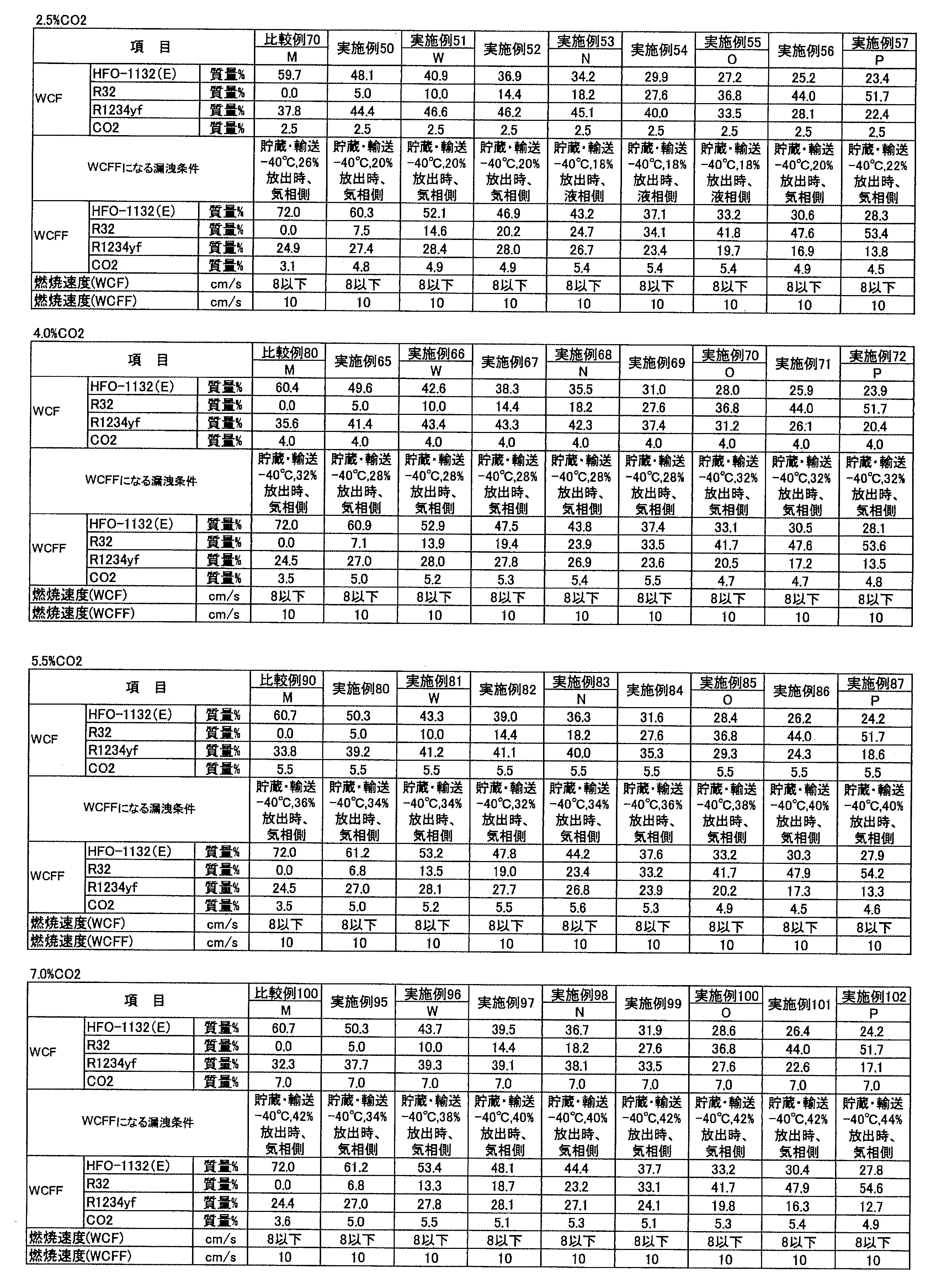
蒸発温度:5℃
凝縮温度:45℃
過熱度:5K
過冷却度;5K
Ecomp(圧縮仕事量):0.7kWh


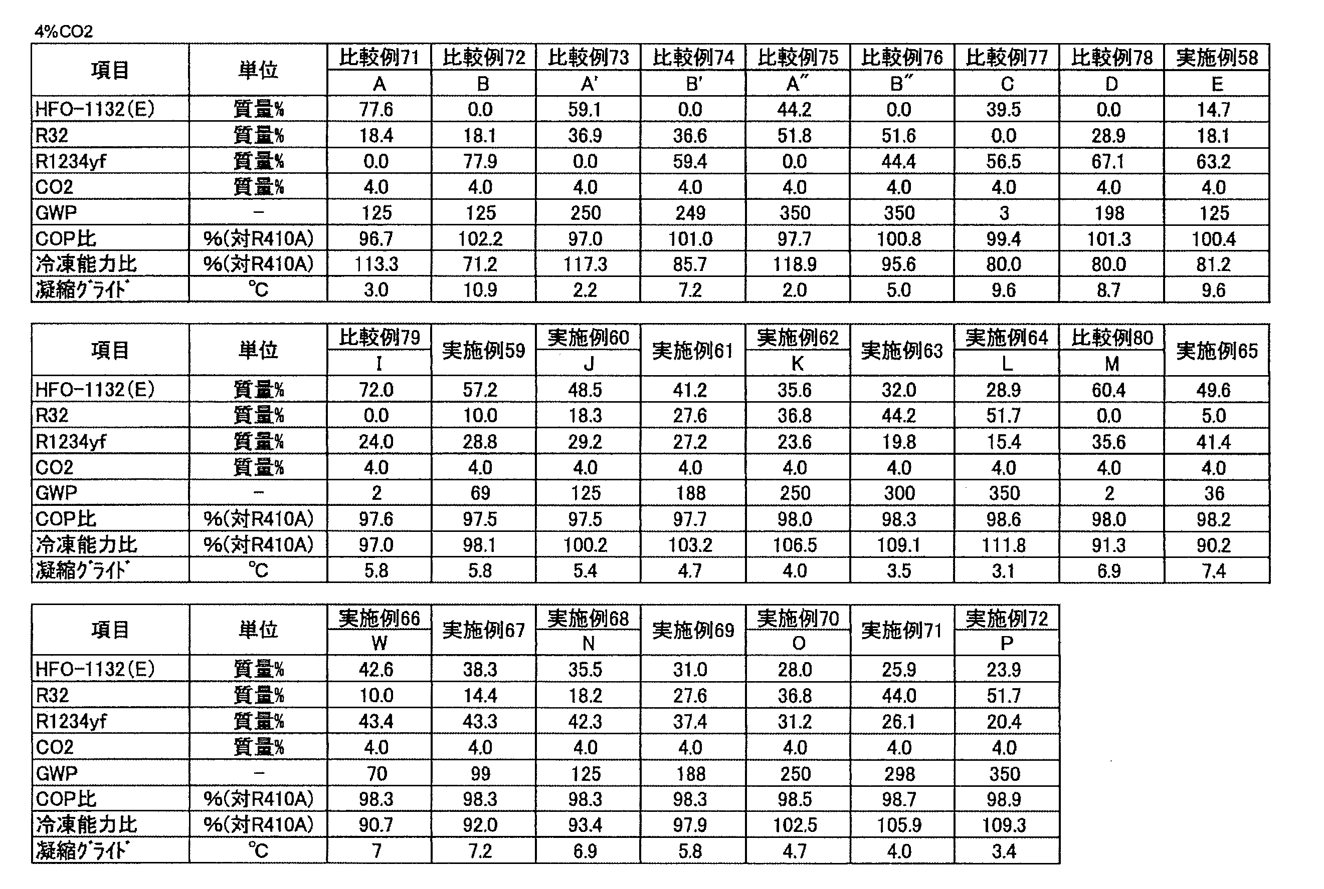

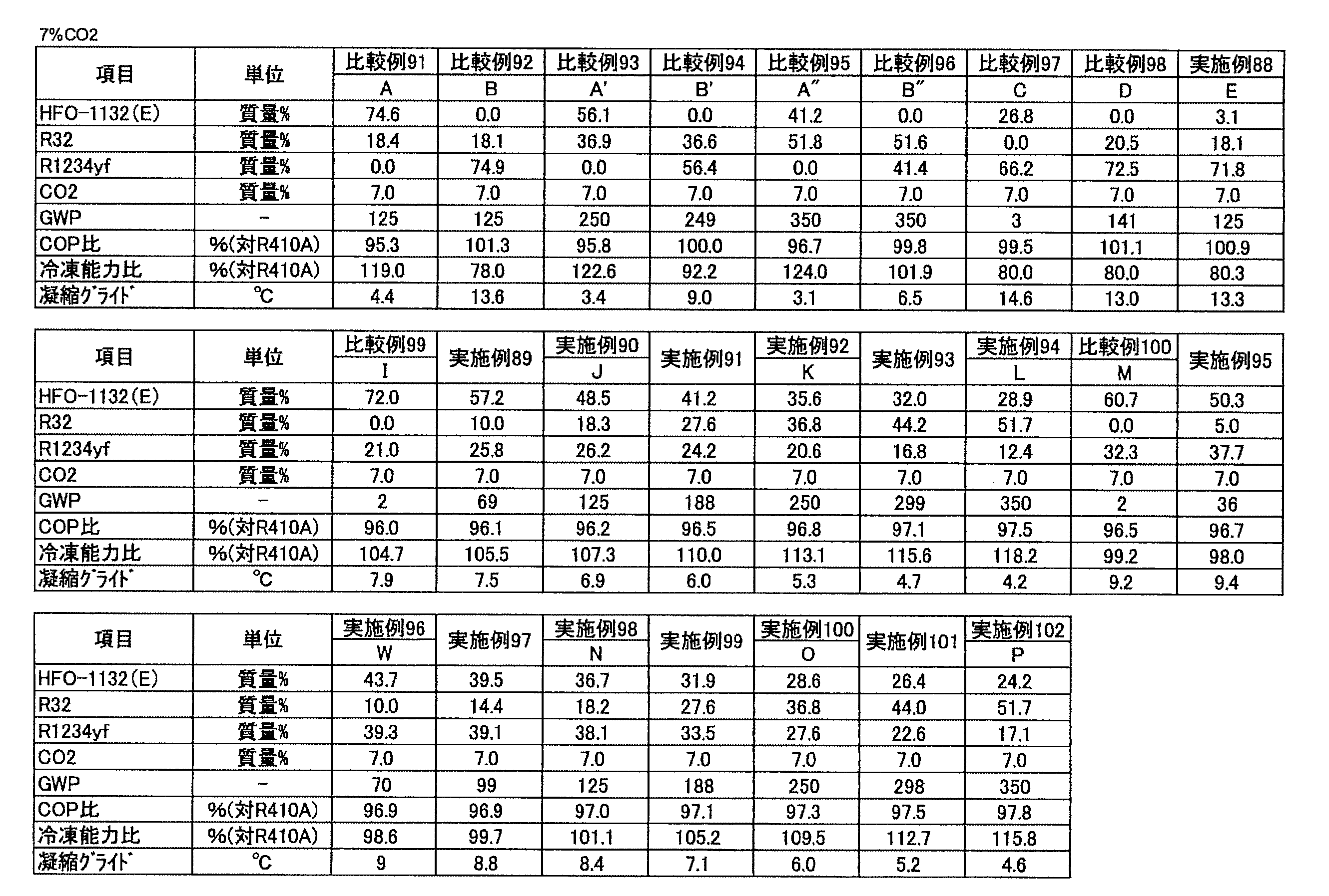
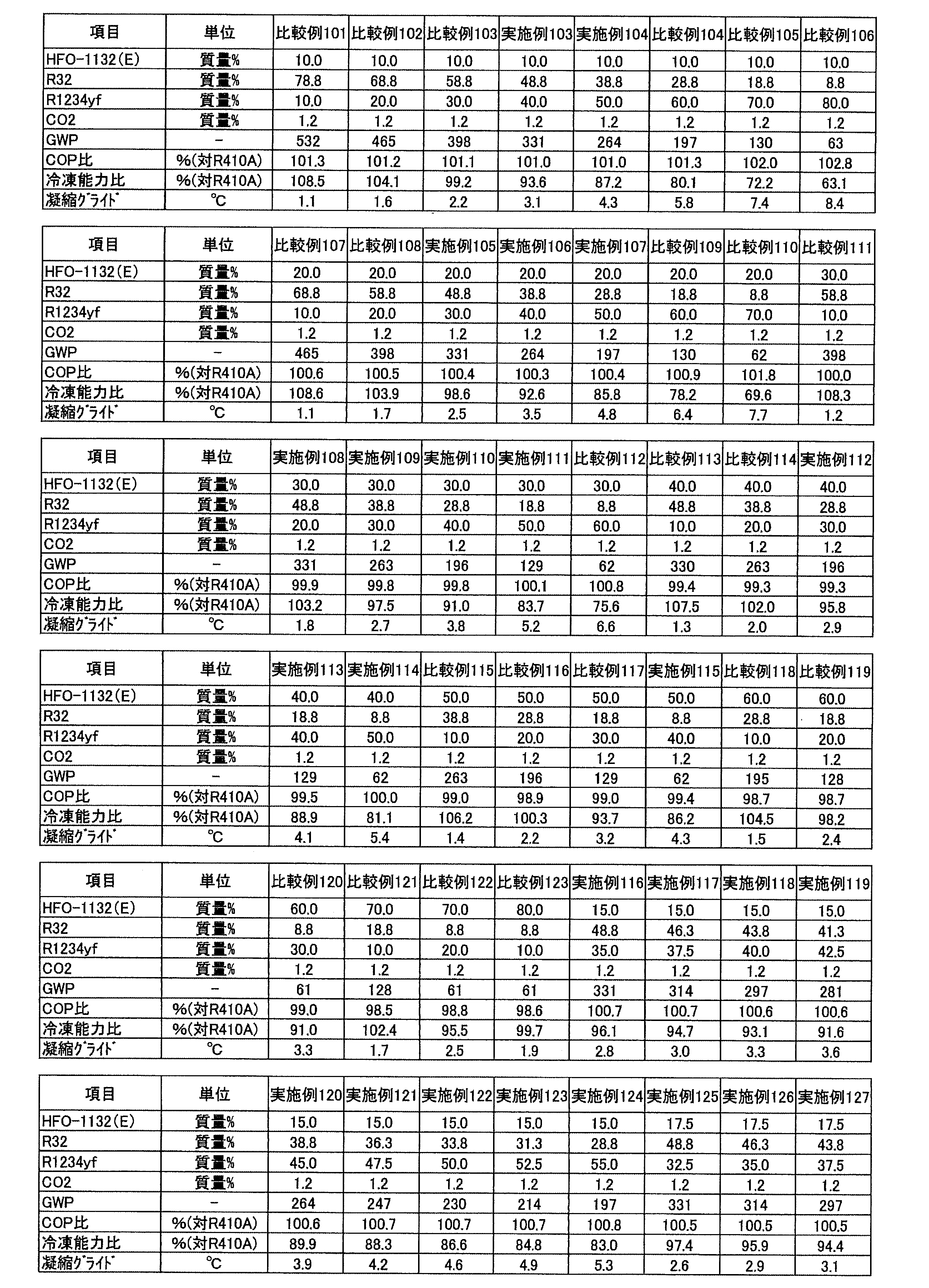
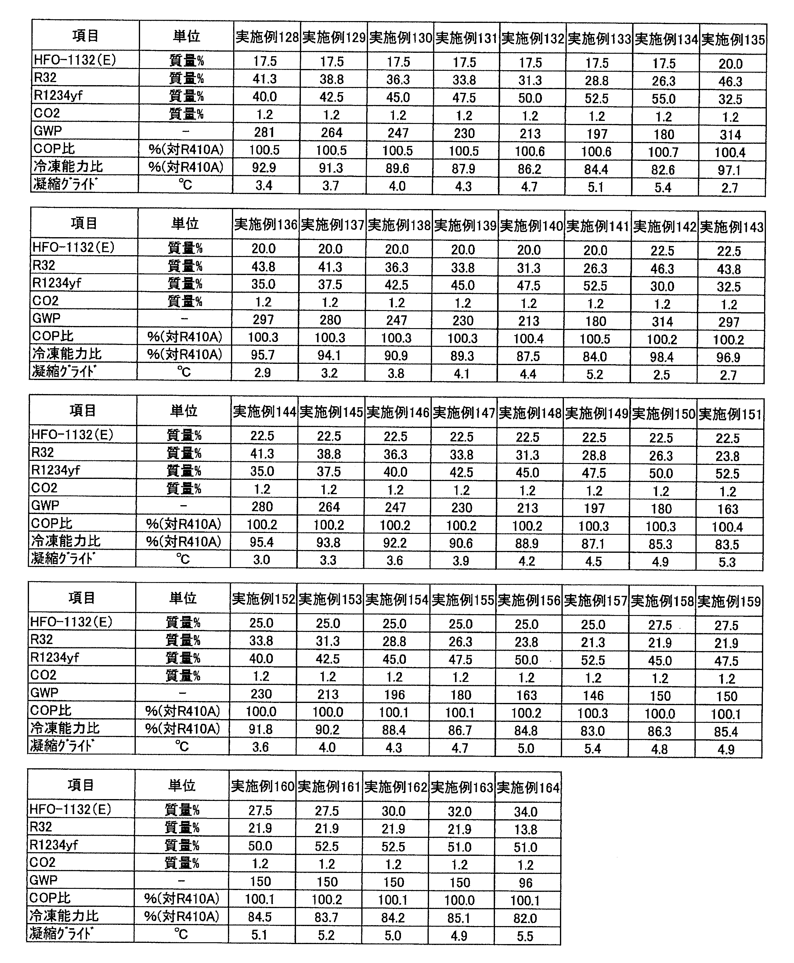
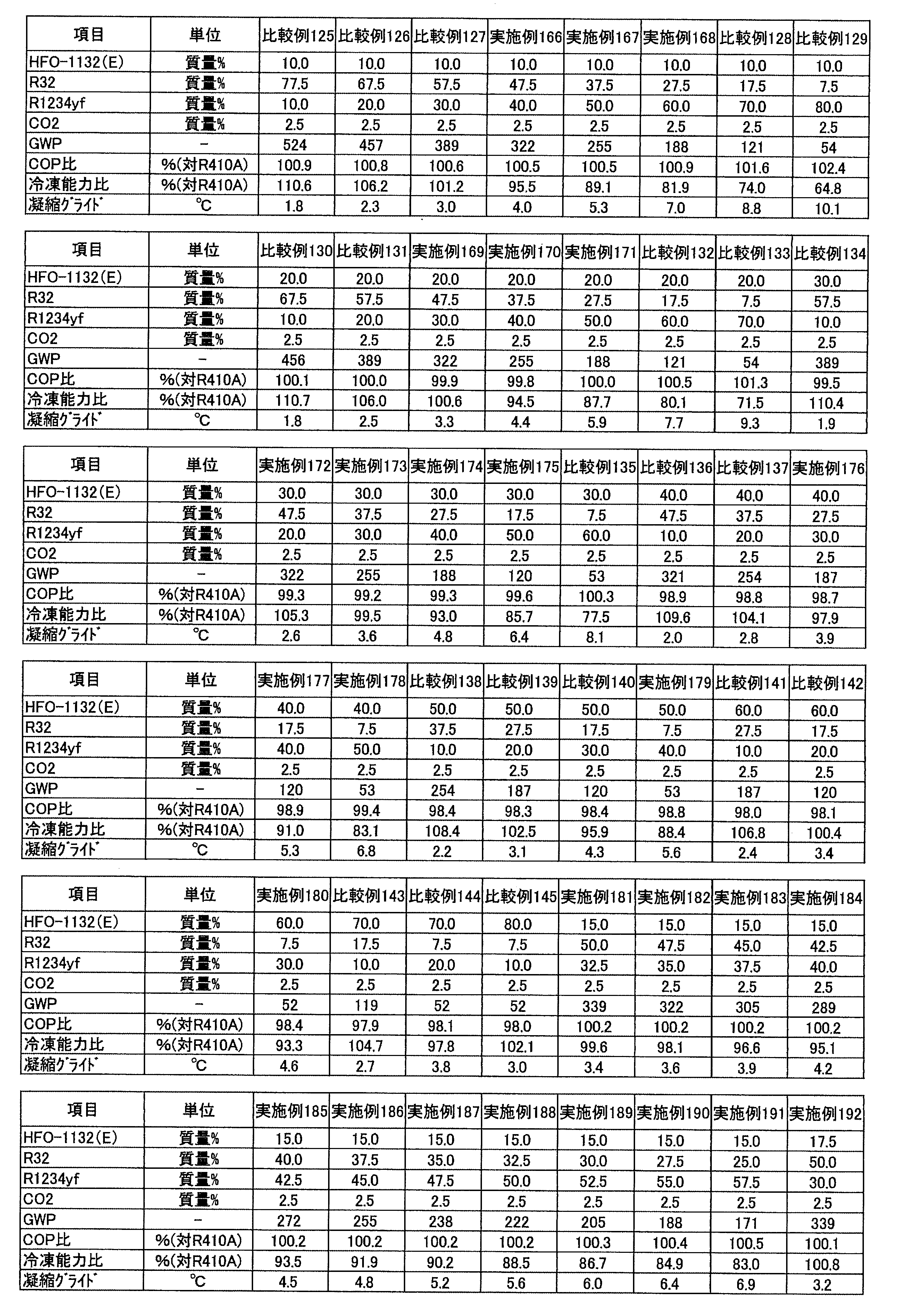

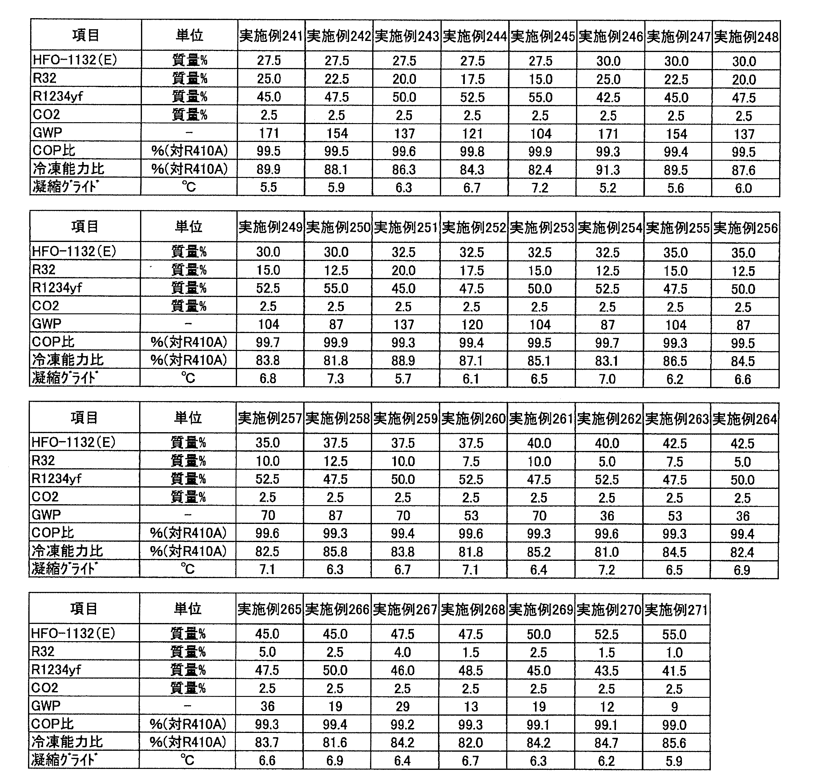

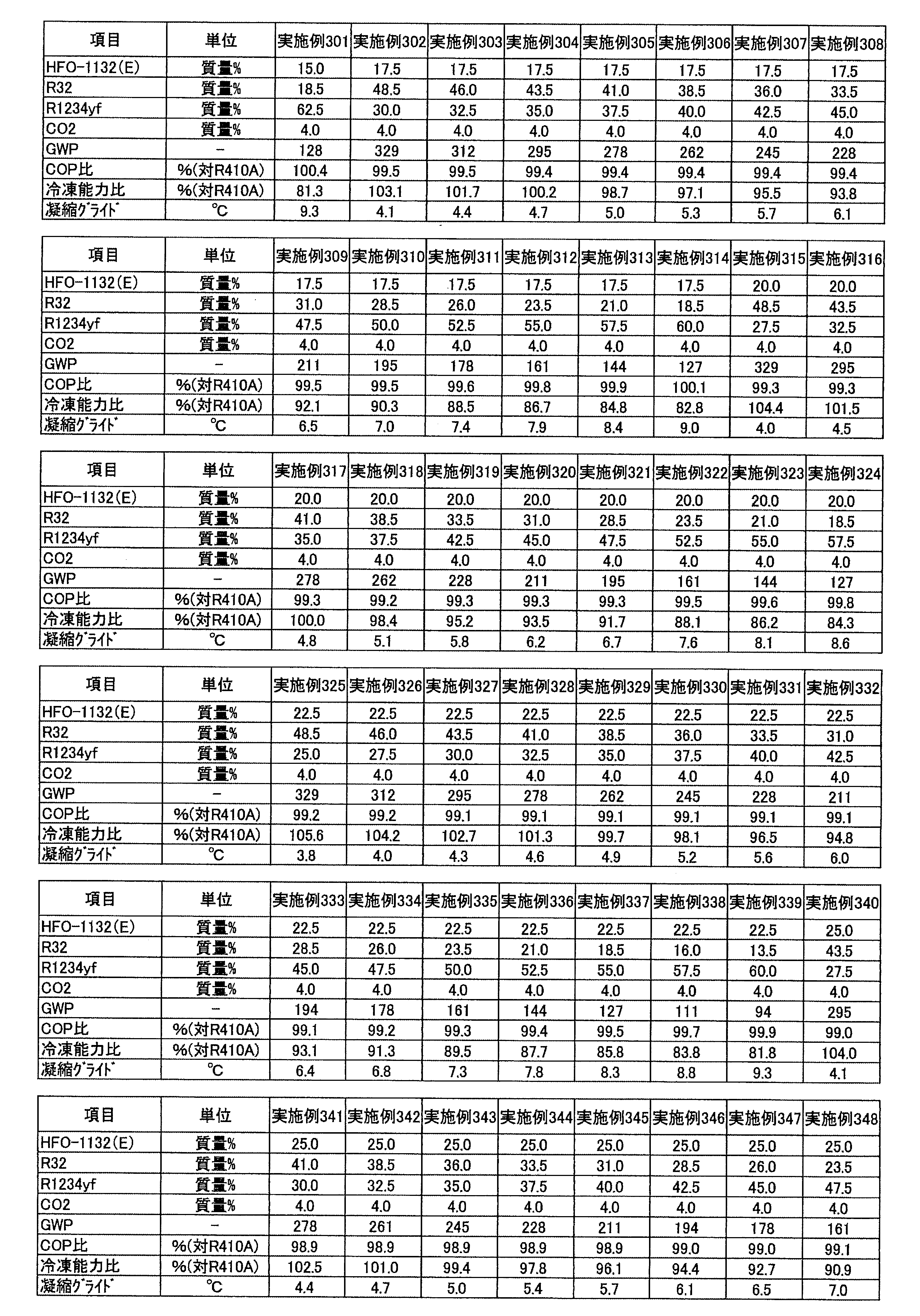


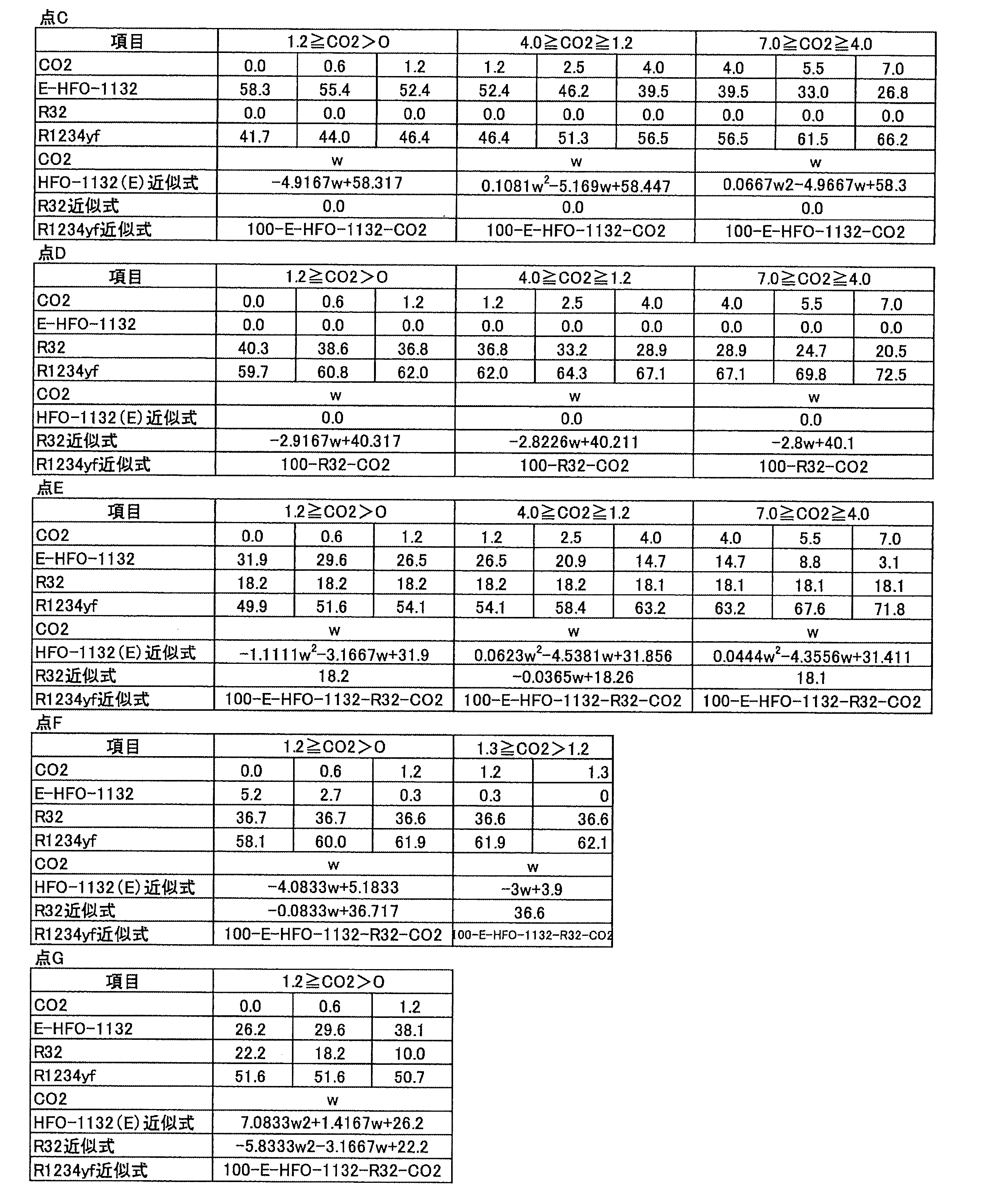


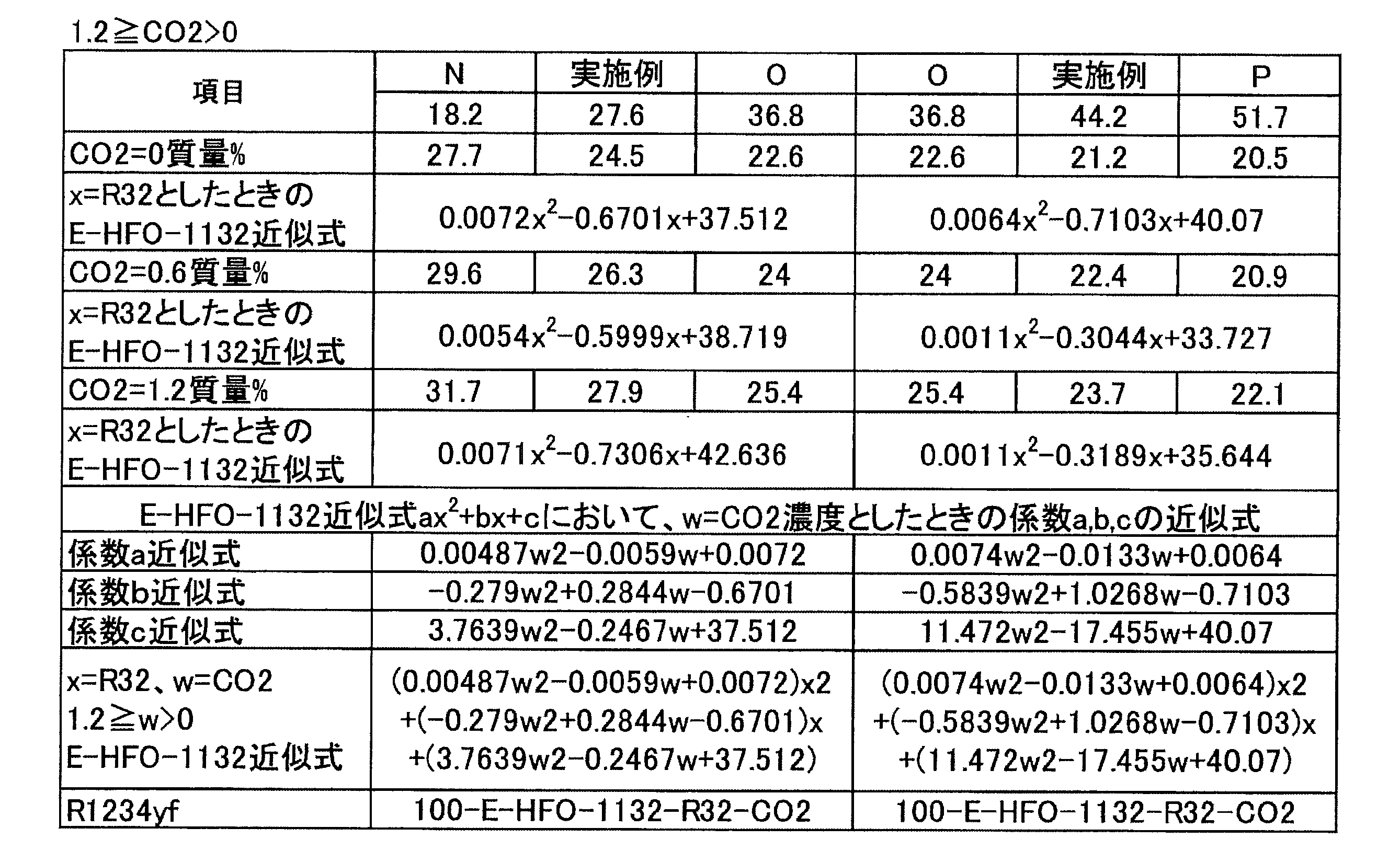

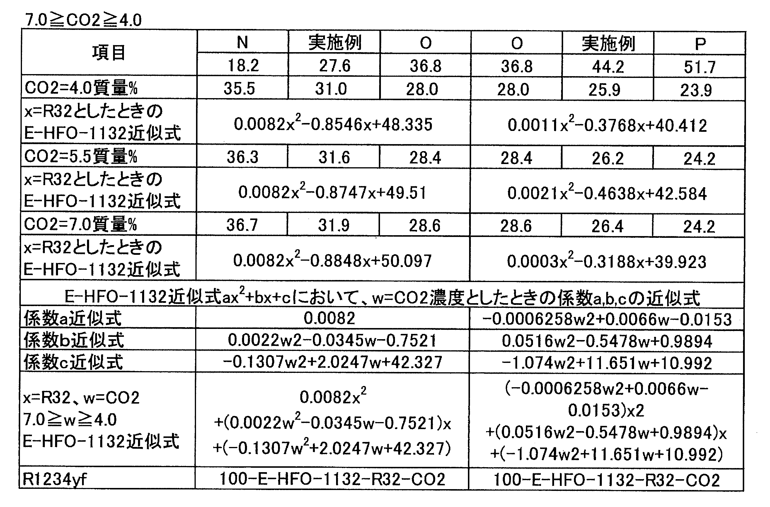
1.組成物
本開示の組成物は冷媒を含有し、当該冷媒としては、「冷媒1」及び「冷媒2」が挙げられる。以下、冷媒1及び冷媒2についてそれぞれ説明する。本明細書において、「本開示の冷媒」とは冷媒1及び冷媒2を意味する。
本開示の組成物に含まれる冷媒は、一つの態様において、HFO-1132(Z)及びHFO-1234yfを含有する。この冷媒を「冷媒1」ということがある。
本開示の組成物に含まれる冷媒は、一つの態様において、HFO-1132(Z)及びHFO-1234yfを含有し、HFO-1132(Z)及びHFO-1234yfの全質量に対して、HFO-1132(Z)の含有割合が41.0~49.2質量%であり、HFO-1234yfの含有割合が59.0~50.8質量%である。この冷媒を「冷媒2」ということがある。
本開示の冷媒を含有する組成物は、作動流体として、1)冷凍サイクルを運転する工程を含む冷凍方法、2)冷凍サイクルを運転する冷凍装置の運転方法等における既存の冷媒の用途に幅広く利用することができる。
本開示の冷媒組成物は、本開示の冷媒を少なくとも含み、本開示の冷媒と同じ用途のために使用することができる。
本開示の冷媒組成物は微量の水を含んでもよい。
トレーサーは、本開示の冷媒組成物が希釈、汚染、その他何らかの変更があった場合、その変更を追跡できるように検出可能な濃度で本開示の冷媒組成物に添加される。
HCC-40(クロロメタン、CH3Cl)
HFC-41(フルオロメタン、CH3F)
HFC-161(フルオロエタン、CH3CH2F)
HFC-245fa(1,1,1,3,3-ペンタフルオロプロパン、CF3CH2CHF2)
HFC-236fa(1,1,1,3,3,3-ヘキサフルオロプロパン、CF3CH2CF3)
HFC-236ea(1,1,1,2,3,3-ヘキサフルオロプロパン、CF3CHFCHF2)
HCFC-22(クロロジフルオロメタン、CHClF2)
HCFC-31(クロロフルオロメタン、CH2ClF)
CFC-1113(クロロトリフルオロエチレン、CF2=CClF)
HFE-125(トリフルオロメチル-ジフルオロメチルエーテル、CF3OCHF2)
HFE-134a(トリフルオロメチル-フルオロメチルエーテル、CF3OCH2F)
HFE-143a(トリフルオロメチル-メチルエーテル、CF3OCH3)
HFE-227ea(トリフルオロメチル-テトラフルオロエチルエーテル、CF3OCHFCF3)
HFE-236fa(トリフルオロメチル-トリフルオロエチルエーテル、CF3OCH2CF3)
本開示の冷媒組成物は、紫外線蛍光染料を1種単独で含有してもよいし、2種以上を含有してもよい。
本開示の冷媒組成物は、安定剤を1種単独で含有してもよいし、2種以上を含有してもよい。
本開示の冷媒組成物は、重合禁止剤を1種単独で含有してもよいし、2種以上を含有してもよい。
本開示の冷媒組成物は、以下の成分も含み得るものとして挙げられる。
本開示の冷凍機油含有作動流体は、本開示の冷媒又は冷媒組成物と、冷凍機油とを少なくとも含み、冷凍装置における作動流体として用いられる。具体的には、本開示の冷凍機油含有作動流体は、冷凍装置の圧縮機において使用される冷凍機油と、冷媒又は冷媒組成物とが互いに混じり合うことにより得られる。
本開示の組成物は、冷凍機油を1種単独で含有してもよいし、2種以上を含有してもよい。
本開示の冷凍機油含有作動流体は、相溶化剤を一種単独で含有してもよいし、二種以上を含有してもよい。
実施例1-1~1-3、比較例1-1~1-6及び参考例1-1(R134a)に示される混合冷媒のGWPは、IPCC第4次報告書の値に基づいて評価した。 これらの混合冷媒のCOP、冷凍能力、吐出温度、飽和温度40℃における飽和圧力、凝縮圧力及び蒸発圧力は、National Institute of Science and Technology(NIST)、Reference Fluid Thermodynamic and Transport Properties Database(Refprop 9.0)を使用し、下記条件で混合冷媒の冷凍サイクル理論計算を実施することにより求めた。
<空調条件>
蒸発温度 10℃
凝縮温度 40℃
過熱温度 20K
過冷却温度 0K
圧縮機効率 70%
「蒸発温度10℃」とは、冷凍装置が備える蒸発器における混合冷媒の蒸発温度が10℃であることを意味する。また、「凝縮温度40℃」とは、冷凍装置が備える凝縮器における混合冷媒の凝縮温度が40℃であることを意味する。
COP=(冷凍能力又は暖房能力)/消費電力量
圧縮比=凝縮圧力(Mpa)/蒸発圧力(Mpa)
試験容器:280mmφ球形(内容積:12リットル)
試験温度:60℃±3℃
圧力:101.3kPa±0.7kPa
水分:乾燥空気1gにつき0.0088g±0.0005g(23℃における相対湿度50%の水分量)
冷媒組成物/空気混合比:1vol.%刻み±0.2vol.%
冷媒組成物混合:±0.1質量%
点火方法:交流放電、電圧15kV、電流30mA、ネオン変圧器
電極間隔:6.4mm(1/4inch)
スパーク:0.4秒±0.05秒
判定基準:
・着火点を中心に90度より大きく火炎が広がった場合=火炎伝播あり(可燃)
・着火点を中心に90度以下の火炎の広がりだった場合=火炎伝播なし(不燃)

実施例1-4~1-6、比較例1-7~1-12及び参考例1-2(R134a)に示される混合冷媒のGWPは、IPCC第4次報告書の値に基づいて評価した。
<空調条件>
蒸発温度 5℃
凝縮温度 45℃
過熱温度 5K
過冷却温度 5K
圧縮機効率 70%
上記用語の意味は、試験例1-1と同様である。

実施例1-7~1-9、比較例1-13~1-18及び参考例1-3(R134a)に示される混合冷媒のGWPは、IPCC第4次報告書の値に基づいて評価した。
<空調条件>
蒸発温度 -10℃
凝縮温度 40℃
過熱温度 20K
過冷却温度 0K
圧縮機効率 70%
上記用語の意味は、試験例1-1と同様である。

実施例1-10~1-12、比較例1-19~1-24及び参考例1-4(R134a)に示される混合冷媒のGWPは、IPCC第4次報告書の値に基づいて評価した。
<空調条件>
蒸発温度 -35℃
凝縮温度 40℃
過熱温度 20K
過冷却温度 0K
圧縮機効率 70%
上記用語の意味は、試験例1-1と同様である。
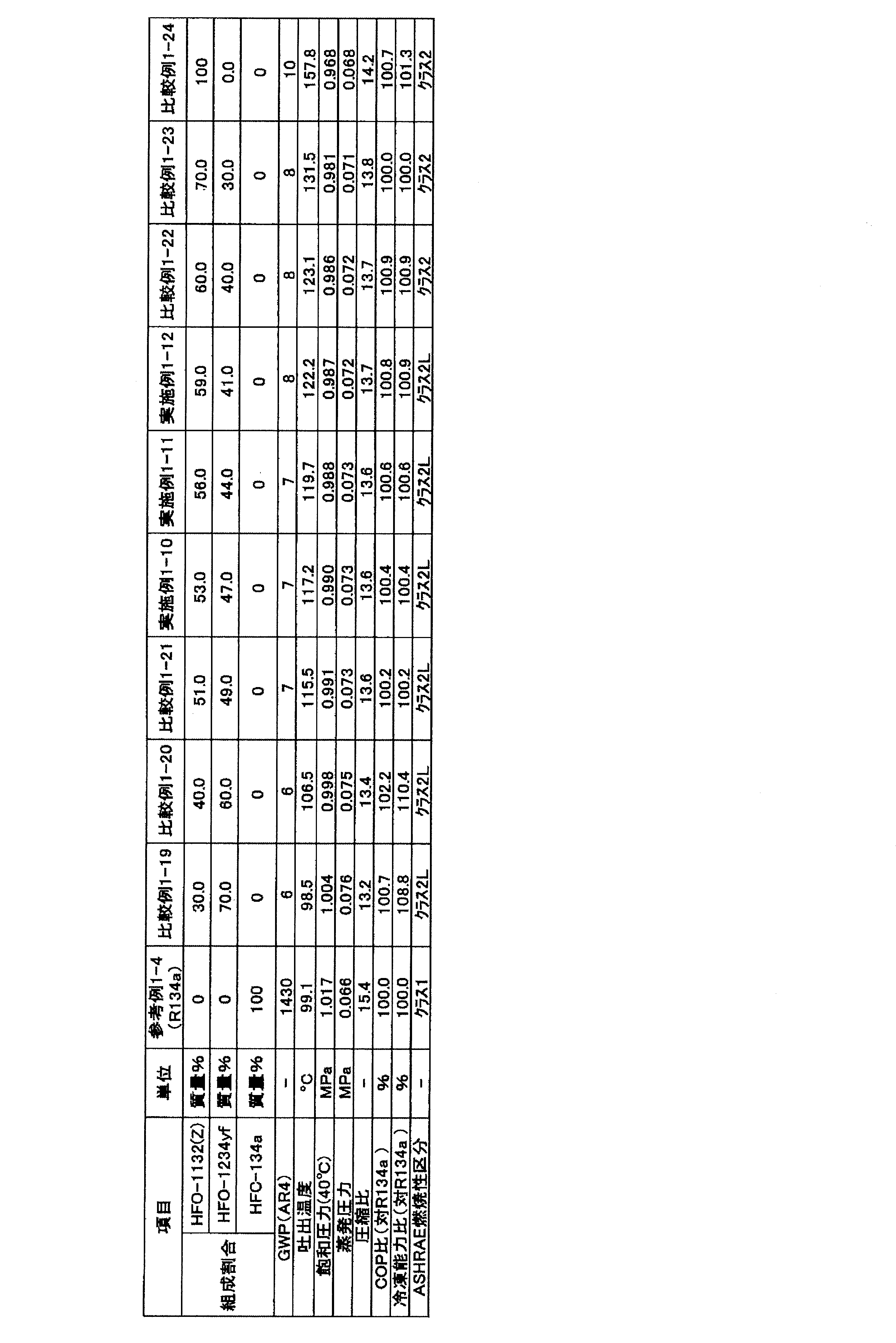
<空調条件>
蒸発温度 -50℃
凝縮温度 40℃
過熱温度 20K
過冷却温度 0K
圧縮機効率 70%
上記用語の意味は、試験例1-1と同様である。

実施例1-16~1-18、比較例1-31~1-36及び参考例1-6(R134a)に示される混合冷媒のGWPは、IPCC第4次報告書の値に基づいて評価した。
<空調条件>
蒸発温度 -65℃
凝縮温度 40℃
過熱温度 20K
過冷却温度 0K
圧縮機効率 70%
上記用語の意味は、試験例1-1と同様である。

<空調条件>
蒸発温度 10℃
凝縮温度 40℃
過熱温度 20K
過冷却温度 0K
圧縮機効率 70%
「蒸発温度10℃」とは、冷凍装置が備える蒸発器における混合冷媒の蒸発温度が10℃であることを意味する。また、「凝縮温度40℃」とは、冷凍装置が備える凝縮器における混合冷媒の凝縮温度が40℃であることを意味する。
COP=(冷凍能力又は暖房能力)/消費電力量
圧縮比=凝縮圧力(Mpa)/蒸発圧力(Mpa)
試験容器:280mmφ球形(内容積:12リットル)
試験温度:60℃±3℃
圧力:101.3kPa±0.7kPa
水分:乾燥空気1gにつき0.0088g±0.0005g(23℃における相対湿度50%の水分量)
冷媒組成物/空気混合比:1vol.%刻み±0.2vol.%
冷媒組成物混合:±0.1質量%
点火方法:交流放電、電圧15kV、電流30mA、ネオン変圧器
電極間隔:6.4mm(1/4inch)
スパーク:0.4秒±0.05秒
判定基準:
・着火点を中心に90度より大きく火炎が広がった場合=火炎伝播あり(可燃)
・着火点を中心に90度以下の火炎の広がりだった場合=火炎伝播なし(不燃)

実施例2-5~2-8、比較例2-7~2-12及び参考例2-2(R134a)に示される混合冷媒のGWPは、IPCC第4次報告書の値に基づいて評価した。
<空調条件>
蒸発温度 5℃
凝縮温度 45℃
過熱温度 5K
過冷却温度 5K
圧縮機効率 70%
上記用語の意味は、試験例2-1と同様である。
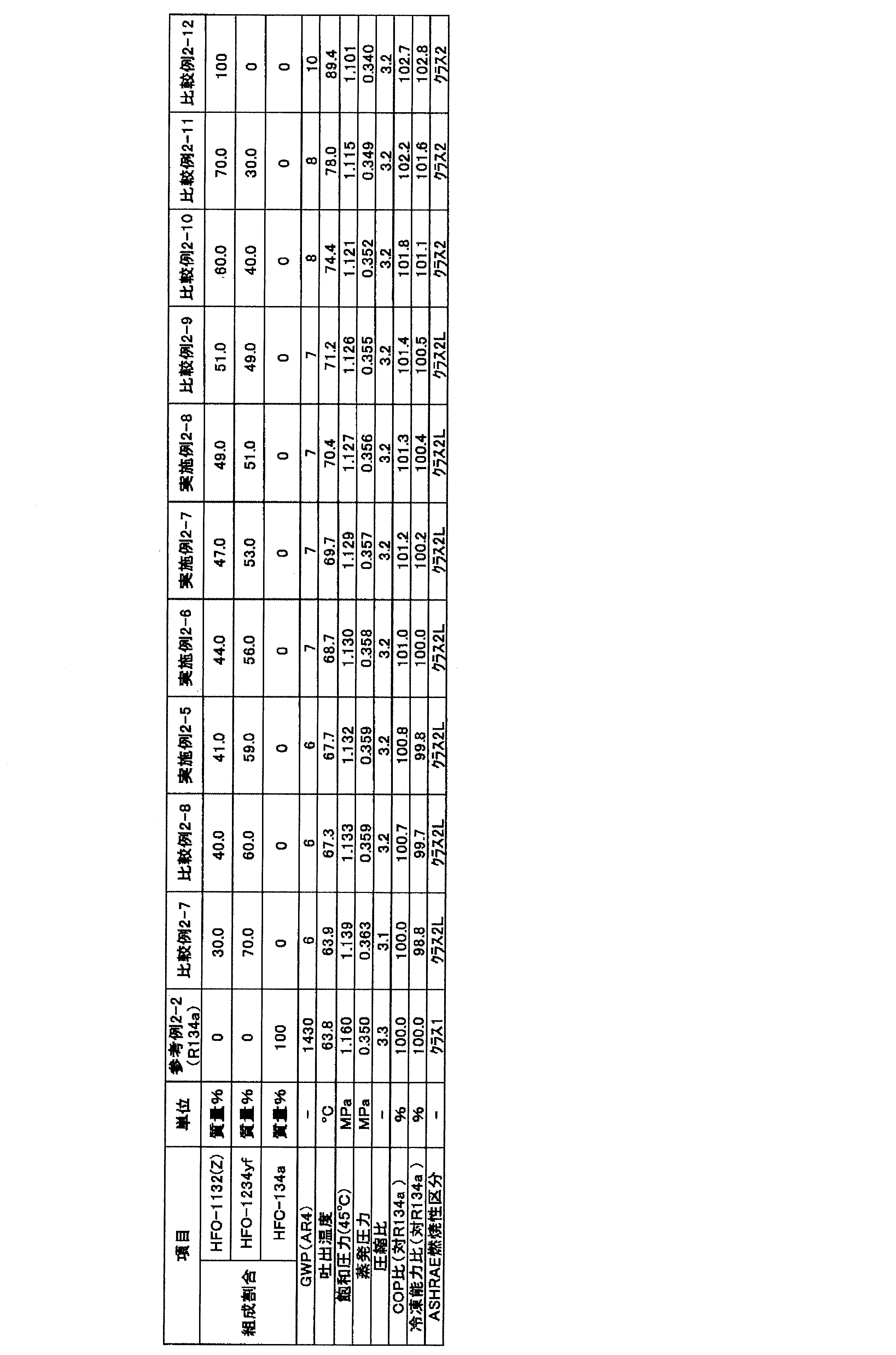
実施例2-9~2-12、比較例2-13~2-18及び参考例2-3(R134a)に示される混合冷媒のGWPは、IPCC第4次報告書の値に基づいて評価した。
<空調条件>
蒸発温度 -10℃
凝縮温度 40℃
過熱温度 20K
過冷却温度 0K
圧縮機効率 70%
上記用語の意味は、試験例2-1と同様である。

実施例2-13~2-16、比較例2-19~2-24及び参考例2-4(R134a)に示される混合冷媒のGWPは、IPCC第4次報告書の値に基づいて評価した。
<空調条件>
蒸発温度 -35℃
凝縮温度 40℃
過熱温度 20K
過冷却温度 0K
圧縮機効率 70%
上記用語の意味は、試験例2-1と同様である。
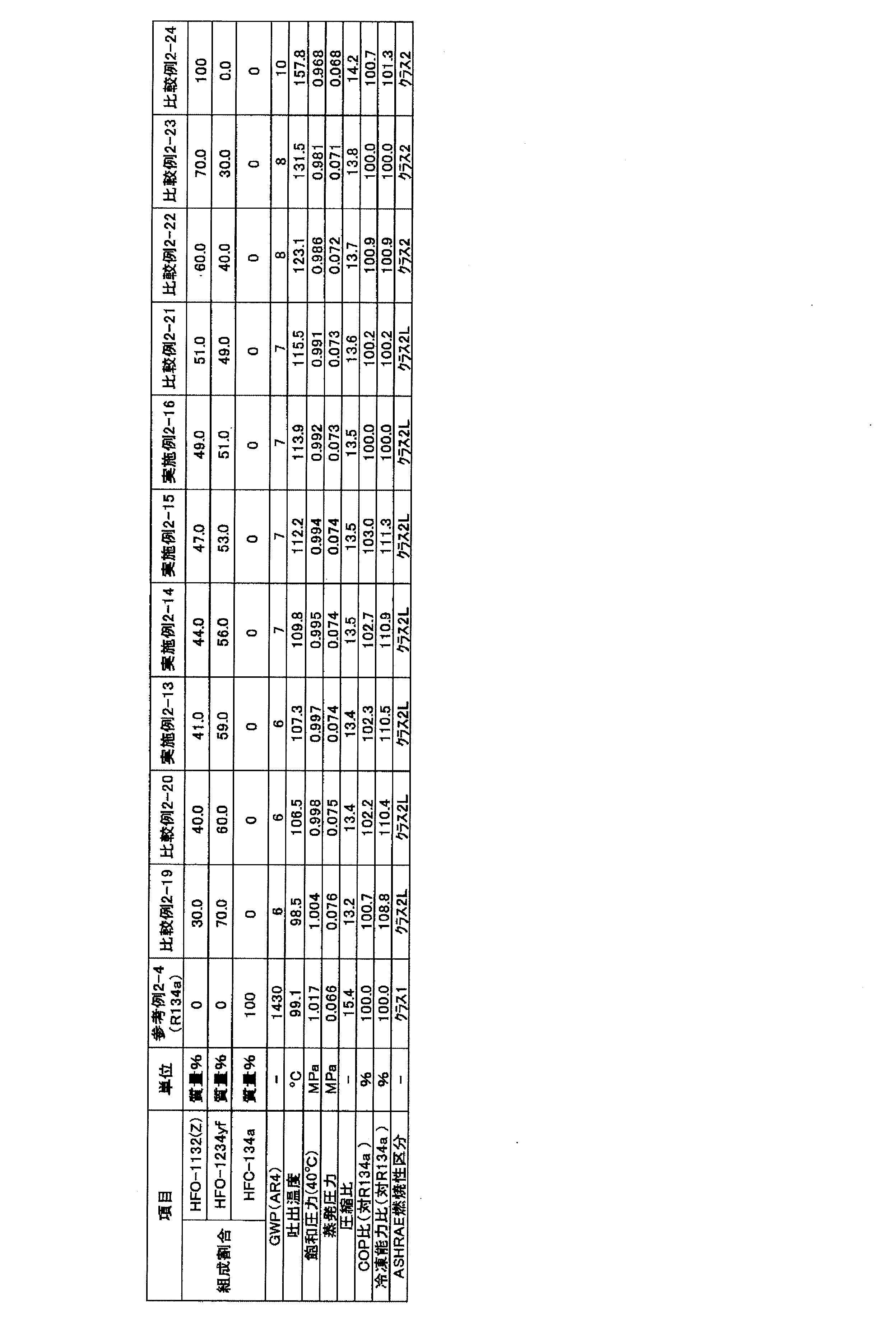
実施例2-17~2-20、比較例2-25~2-30及び参考例2-5(R134a)に示される混合冷媒のGWPは、IPCC第4次報告書の値に基づいて評価した。
<空調条件>
蒸発温度 -50℃
凝縮温度 40℃
過熱温度 20K
過冷却温度 0K
圧縮機効率 70%
上記用語の意味は、試験例2-1と同様である。

実施例2-21~2-24、比較例2-31~2-36及び参考例2-6(R134a)に示される混合冷媒のGWPは、IPCC第4次報告書の値に基づいて評価した。
<空調条件>
蒸発温度 -65℃
凝縮温度 40℃
過熱温度 20K
過冷却温度 0K
圧縮機効率 70%
上記用語の意味は、試験例2-1と同様である。

(1-3-3-1)冷媒組成物
本開示の冷媒組成物は、本開示の冷媒を少なくとも含み、本開示の冷媒と同じ用途のために使用することができる。また、本開示の冷媒組成物は、さらに少なくとも冷凍機油と混合することにより冷凍機用作動流体を得るために用いることができる。
本開示の冷媒組成物は微量の水を含んでもよい。冷媒組成物における含水割合は、冷媒全体に対して、0.1質量%以下とすることが好ましい。冷媒組成物が微量の水分を含むことにより、冷媒中に含まれ得る不飽和のフルオロカーボン系化合物の分子内二重結合が安定化され、また、不飽和のフルオロカーボン系化合物の酸化も起こりにくくなるため、冷媒組成物の安定性が向上する。
トレーサーは、本開示の冷媒組成物が希釈、汚染、その他何らかの変更があった場合、その変更を追跡できるように検出可能な濃度で本開示の冷媒組成物に添加される。
FC-14(テトラフルオロメタン、CF4)
HCC-40(クロロメタン、CH3Cl)
HFC-23(トリフルオロメタン、CHF3)
HFC-41(フルオロメタン、CH3Cl)
HFC-125(ペンタフルオロエタン、CF3CHF2)
HFC-134a(1,1,1,2-テトラフルオロエタン、CF3CH2F)
HFC-134(1,1,2,2-テトラフルオロエタン、CHF2CHF2)
HFC-143a(1,1,1-トリフルオロエタン、CF3CH3)
HFC-143(1,1,2-トリフルオロエタン、CHF2CH2F)
HFC-152a(1,1-ジフルオロエタン、CHF2CH3)
HFC-152(1,2-ジフルオロエタン、CH2FCH2F)
HFC-161(フルオロエタン、CH3CH2F)
HFC-245fa(1,1,1,3,3-ペンタフルオロプロパン、CF3CH2CHF2)
HFC-236fa(1,1,1,3,3,3-ヘキサフルオロプロパン、CF3CH2CF3)
HFC-236ea(1,1,1,2,3,3-ヘキサフルオロプロパン、CF3CHFCHF2)
HFC-227ea(1,1,1,2,3,3,3-ヘプタフルオロプロパン、CF3CHFCF3)
HCFC-22(クロロジフルオロメタン、CHClF2)
HCFC-31(クロロフルオロメタン、CH2ClF)
CFC-1113(クロロトリフルオロエチレン、CF2=CClF)
HFE-125(トリフルオロメチル-ジフルオロメチルエーテル、CF3OCHF2)
HFE-134a(トリフルオロメチル-フルオロメチルエーテル、CF3OCH2F)
HFE-143a(トリフルオロメチル-メチルエーテル、CF3OCH3)
HFE-227ea(トリフルオロメチル-テトラフルオロエチルエーテル、CF3OCHFCF3)
HFE-236fa(トリフルオロメチル-トリフルオロエチルエーテル、CF3OCH2CF3)
本開示の冷媒組成物は、紫外線蛍光染料として、一種を単独で含有してもよいし、二種以上を含有してもよい。
本開示の冷媒組成物は、安定剤として、一種を単独で含有してもよいし、二種以上を含有してもよい。
本開示の冷媒組成物は、重合禁止剤として、一種を単独で含有してもよいし、二種以上を含有してもよい。
本開示の冷凍機油含有作動流体は、本開示の冷媒又は冷媒組成物と、冷凍機油とを少なくとも含み、冷凍機における作動流体として用いられる。具体的には、本開示の冷凍機油含有作動流体は、冷凍機の圧縮機において使用される冷凍機油と、冷媒又は冷媒組成物とが互いに混じり合うことにより得られる。冷凍機油含有作動流体には冷凍機油は一般に10~50質量%含まれる。
本開示の組成物は、冷凍機油として、一種を単独で含有してもよいし、二種以上を含有してもよい。
本開示の冷凍機油含有作動流体は、相溶化剤として、一種を単独で含有してもよいし、二種以上を含有してもよい。
以下、本開示において用いられる冷媒である冷媒A~冷媒Eについて、詳細に説明する。
冷媒Aとしては、「冷媒A1」及び「冷媒A2」が挙げられる。以下、冷媒A1及び冷媒A2についてそれぞれ説明する。本開示において、冷媒A1及び冷媒A2は、それぞれ混合冷媒である。
冷媒A1は、HFO-1132(E)、HFC-32及びHFO-1234yfを必須成分として含有する混合冷媒である。以下、本項目において、HFO-1132(E)、HFC-32及びHFO-1234yfを「三成分」とも称する。
点A(HFO-1132(E)/HFC-32/HFO-1234yf=51.8/1.0/47.2質量%)、
点B(HFO-1132(E)/HFC-32/HFO-1234yf=35.3/1.0/63.7質量%)、
点C(HFO-1132(E)/HFC-32/HFO-1234yf=10.1/18.0/71.9質量%)及び
点D(HFO-1132(E)/HFC-32/HFO-1234yf=27.8/18.0/54.2質量%)、
の4点を通る図形で囲まれた領域の範囲内にある。
点A(HFO-1132(E)/HFC-32/HFO-1234yf=51.8/1.0/47.2質量%)、
点B(HFO-1132(E)/HFC-32/HFO-1234yf=35.3/1.0/63.7質量%)、
点C(HFO-1132(E)/HFC-32/HFO-1234yf=10.1/18.0/71.9質量%)及び
点D(HFO-1132(E)/HFC-32/HFO-1234yf=27.8/18.0/54.2質量%)、
の4点をそれぞれ結ぶ直線a、曲線b、直線c及び曲線dで囲まれた領域の範囲内にある。
A:ANSI/ASHRAE34-2013規格に従い測定された燃焼速度が5cm/sであって、HFC-32の濃度(質量%)が1.0質量%である質量比
B:HFC-32の濃度(質量%)が1.0質量%であって、冷凍能力がR404Aに対して95%である質量比
C:冷凍能力がR404Aに対して95%であって、GWPが125である質量比
D:GWPが125であって、ANSI/ASHRAE34-2013規格に従い測定された燃焼速度が5cm/sである質量比
「ANSI/ASHRAE34-2013規格に従い測定された燃焼速度が5cm/s」とは、ANSI/ASHRAE34-2013規格でのクラス2L(微燃)に区分するための基準である燃焼速度(10cm/s)の半分の数値であり、クラス2Lに規定される冷媒の中でも比較的安全であることを意味する。具体的には、「燃焼速度(10cm/s)の半分の数値」であると、万が一着火した場合にも火炎が伝播しにくいという点で比較的安全である。なお、以下ANSI/ASHRAE34-2013規格に従い測定された燃焼速度を、単に「燃焼速度」とも称する。
また、直線aよりも三角組成図の頂点HFC-32側の領域では、予想外に冷凍能力が大きい。
y=1.0
z=100-x-y
35.3≦x≦51.8

y=18.0
z=100-x-y
10.1≦x≦27.8
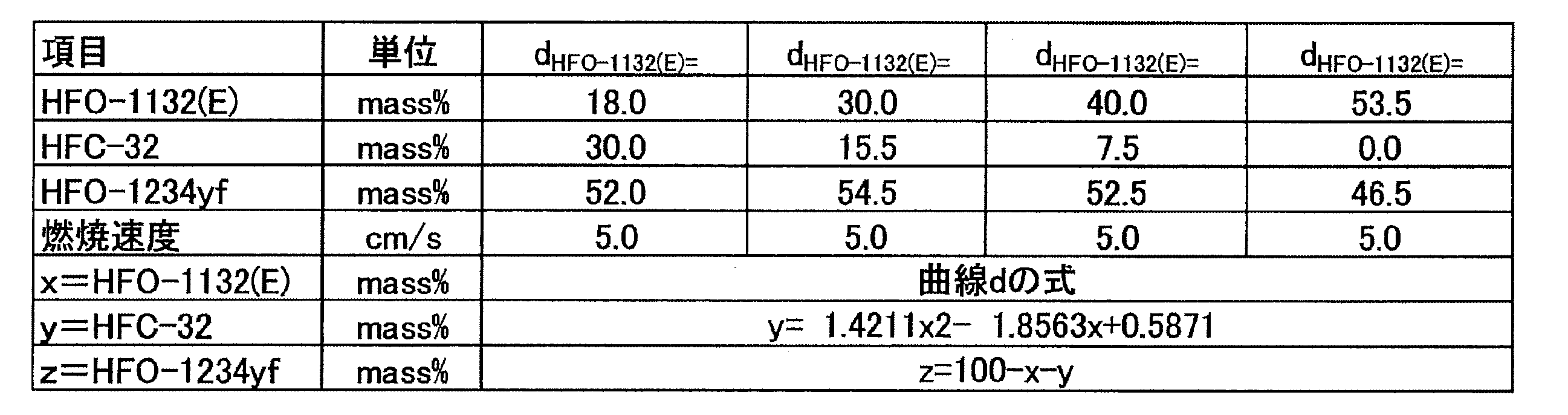
点A(HFO-1132(E)/HFC-32/HFO-1234yf=51.8/1.0/47.2質量%)、
点B(HFO-1132(E)/HFC-32/HFO-1234yf=35.3/1.0/63.7質量%)、
点E(HFO-1132(E)/HFC-32/HFO-1234yf=15.2/14.3/70.5質量%)及び
点F(HFO-1132(E)/HFC-32/HFO-1234yf=31.1/14.3/54.6質量%)、
の4点を通る図形で囲まれた領域の範囲内にあることが好ましい。
点A(HFO-1132(E)/HFC-32/HFO-1234yf=51.8/1.0/47.2質量%)、
点B(HFO-1132(E)/HFC-32/HFO-1234yf=35.3/1.0/63.7質量%)、
点E(HFO-1132(E)/HFC-32/HFO-1234yf=15.2/14.3/70.5質量%)及び
点F(HFO-1132(E)/HFC-32/HFO-1234yf=31.1/14.3/54.6質量%)
の4点をそれぞれ結ぶ直線a、曲線b、直線e及び曲線dで囲まれた領域の範囲内にあることが好ましい。
E:冷凍能力がR404Aに対して95%であって、GWPが100である質量比
F:GWPが100であって、ANSI/ASHRAE34-2013規格に従い測定された燃焼速度が5cm/sである、GWP=100の質量比
y=14.3
z=100-x-y
15.2≦x≦31.1
点A(HFO-1132(E)/HFC-32/HFO-1234yf=51.8/1.0/47.2質量%)、
点B(HFO-1132(E)/HFC-32/HFO-1234yf=35.3/1.0/63.7質量%)、
点C(HFO-1132(E)/HFC-32/HFO-1234yf=10.1/18.0/71.9質量%)及び
点D(HFO-1132(E)/HFC-32/HFO-1234yf=27.8/18.0/54.2質量%)、
の4点を通る図形で囲まれた領域の範囲内にあることが好ましい。
点A(HFO-1132(E)/HFC-32/HFO-1234yf=51.8/1.0/47.2質量%)、
点B(HFO-1132(E)/HFC-32/HFO-1234yf=35.3/1.0/63.7質量%)、
点E(HFO-1132(E)/HFC-32/HFO-1234yf=15.2/14.3/70.5質量%)及び
点F(HFO-1132(E)/HFC-32/HFO-1234yf=31.1/14.3/54.6質量%)、
の4点を通る図形で囲まれた領域の範囲内にあることがより好ましい。
冷媒A2は、HFO-1132(E)、HFC-32及びHFO-1234yfを必須成分として含有する混合冷媒である。以下、本項目において、HFO-1132(E)、HFC-32及びHFO-1234yfを「三成分」とも称する。
点P(HFO-1132(E)/HFC-32/HFO-1234yf=45.6/1.0/53.4質量%)、
点B(HFO-1132(E)/HFC-32/HFO-1234yf=35.3/1.0/63.7質量%)、
点Q(HFO-1132(E)/HFC-32/HFO-1234yf=1.0/24.8/74.2質量%)、
点R(HFO-1132(E)/HFC-32/HFO-1234yf=1.0/29.2/69.8質量%)及び
点S(HFO-1132(E)/HFC-32/HFO-1234yf=6.5/29.2/64.3質量%)、
の5点を通る図形で囲まれた領域の範囲内にある、組成物。
点P(HFO-1132(E)/HFC-32/HFO-1234yf=45.6/1.0/53.4質量%)、
点B(HFO-1132(E)/HFC-32/HFO-1234yf=35.3/1.0/63.7質量%)、
点Q(HFO-1132(E)/HFC-32/HFO-1234yf=1.0/24.8/74.2質量%)、
点R(HFO-1132(E)/HFC-32/HFO-1234yf=1.0/29.2/69.8質量%)及び
点S(HFO-1132(E)/HFC-32/HFO-1234yf=6.5/29.2/64.3質量%)、
の5点をそれぞれ結ぶ直線p、曲線q、直線r、直線s及び曲線tで囲まれた領域の範囲内にある。
P:40℃での圧力が1.85MPaであって、HFC-32の濃度(質量%)が1.0質量%である質量比
B:HFC-32の濃度(質量%)が1.0質量%であって、冷凍能力がR404Aに対して95%である質量比
Q:冷凍能力がR404Aに対して95%であって、HFO-1132(E)の濃度(質量%)が1.0質量%である質量比
R:HFO-1132(E)の濃度(質量%)が1.0質量%であって、GWPが200である質量比
S:GWPが200であって、40℃での圧力が1.85MPaである質量比
「40℃での圧力が1.85MPaになる質量比」とは、温度40(℃)での飽和圧力が1.85MPaである質量比を意味する。
y=1.0
z=100-x-y
35.3≦x≦45.6

x=1.0
z=100-x-y
24.8≦y≦29.2
y=29.2
z=100-x-y
1.0≦x≦6.5
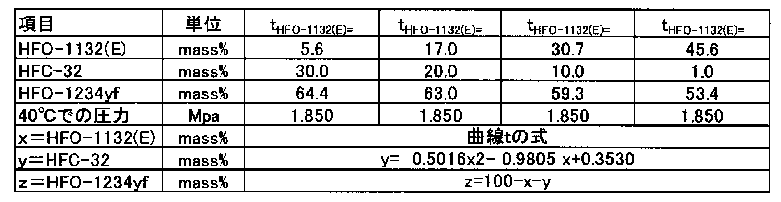
点P(HFO-1132(E)/HFC-32/HFO-1234yf=45.6/1.0/53.4質量%)、
点B(HFO-1132(E)/HFC-32/HFO-1234yf=35.3/1.0/63.7質量%)、
点Q(HFO-1132(E)/HFC-32/HFO-1234yf=1.0/24.8/74.2質量%)、
点R(HFO-1132(E)/HFC-32/HFO-1234yf=1.0/29.2/69.8質量%)及び
点S(HFO-1132(E)/HFC-32/HFO-1234yf=6.5/29.2/64.3質量%)、
の5点を通る図形で囲まれた領域の範囲内にあることが好ましい。
以下に、実施例を挙げて更に詳細に説明する。ただし、本開示は、これらの実施例に限定されるものではない。
実施例1-1~1-11、比較例1-1~1-6及び参考例1-1(R404A)に示される混合冷媒のGWPは、IPCC(Intergovernmental Panel on Climate Change)第4次報告書の値に基づいて評価した。
蒸発温度 -40℃
凝縮温度 40℃
過熱温度 20K
過冷却温度 0K
圧縮機効率 70%
COP=(冷凍能力又は暖房能力)/消費電力量
試験容器:280mmφ球形(内容積:12リットル)
試験温度:60℃±3℃
圧力:101.3kPa±0.7kPa
水分:乾燥空気1gにつき0.0088g±0.0005g(23℃における相対湿度50%の水分量)
冷媒組成物/空気混合比:1vol.%刻み±0.2vol.%
冷媒組成物混合:±0.1質量%
点火方法:交流放電、電圧15kV、電流30mA、ネオン変圧器
電極間隔:6.4mm(1/4inch)
スパーク:0.4秒±0.05秒
判定基準:
・着火点を中心に90度より大きく火炎が広がった場合=火炎伝播あり(可燃)
・着火点を中心に90度以下の火炎の広がりだった場合=火炎伝播なし(不燃)

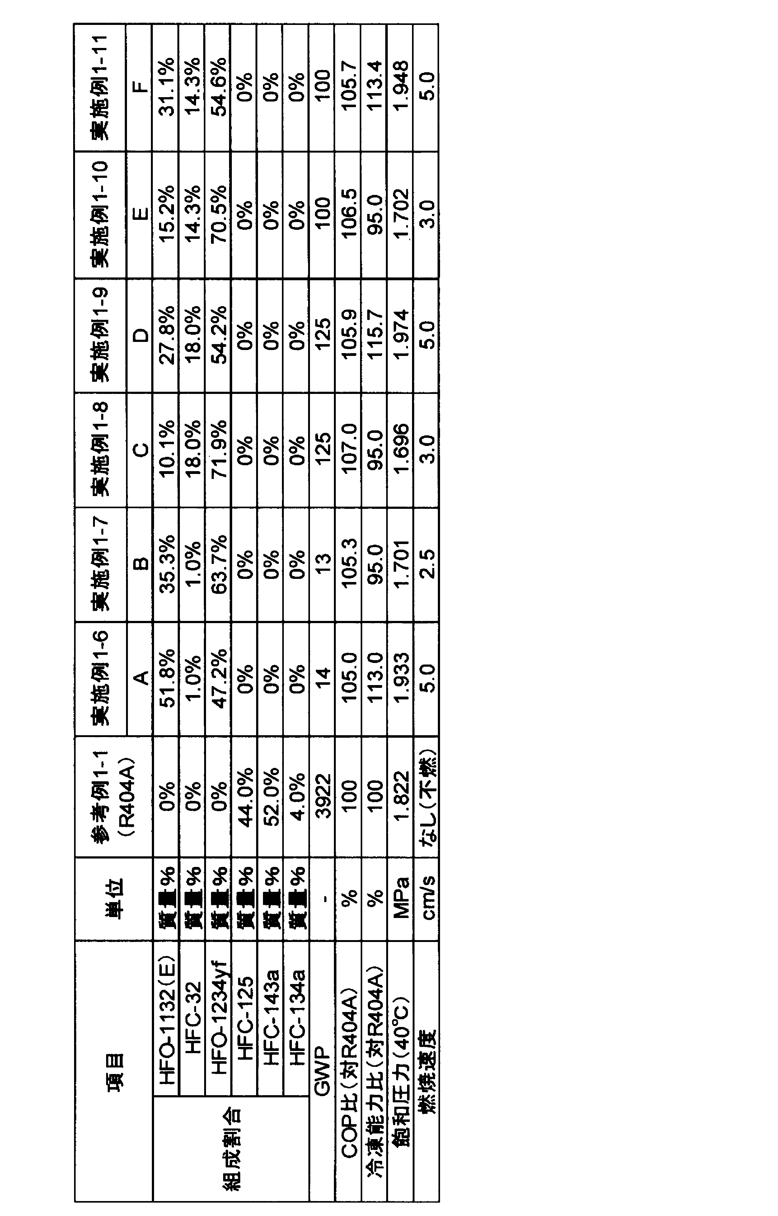
実施例2-1~2-11、比較例2-1~2-5及び参考例2-1(R404A)に示される混合冷媒のGWPは、IPCC第4次報告書の値に基づいて評価した。
蒸発温度 -40℃
凝縮温度 40℃
過熱温度 20K
過冷却温度 0K
圧縮機効率 70%
COP=(冷凍能力又は暖房能力)/消費電力量


冷媒Bは、HFO-1132(E)、HFO-1123及びHFO-1234yfを必須成分として含有する混合冷媒である。以下、本項目において、HFO-1132(E)、HFO-1123及びHFO-1234yfを「三成分」とも称する。
点A(HFO-1132(E)/HFO-1123/HFO-1234yf=42.5/1.0/56.5質量%)、
点B(HFO-1132(E)/HFO-1123/HFO-1234yf=27.1/1.0/71.9質量%)、
点C(HFO-1132(E)/HFO-1123/HFO-1234yf=1.0/30.4/68.6質量%)、
点D(HFO-1132(E)/HFO-1123/HFO-1234yf=1.0/57.0/42.0質量%)及び
点E(HFO-1132(E)/HFO-1123/HFO-1234yf=42.5/24.1/33.4質量%)
の5点を通る図形で囲まれた領域の範囲内にある。
点A(HFO-1132(E)/HFO-1123/HFO-1234yf=42.5/1.0/56.5質量%)、
点B(HFO-1132(E)/HFO-1123/HFO-1234yf=27.1/1.0/71.9質量%)、
点C(HFO-1132(E)/HFO-1123/HFO-1234yf=1.0/30.4/68.6質量%)、
点D(HFO-1132(E)/HFO-1123/HFO-1234yf=1.0/57.0/42.0質量%)及び
点E(HFO-1132(E)/HFO-1123/HFO-1234yf=42.5/24.1/33.4質量%)
の5点をそれぞれ結ぶ直線a、曲線b、直線c、曲線d及び直線eで囲まれた領域の範囲内にある。
A:ANSI/ASHRAE34-2013規格に従い測定された燃焼速度が3.0cm/sであって、HFO-1123の濃度(質量%)が1.0質量%である質量比
B:HFO-1123の濃度(質量%)が1.0質量%であって、冷凍能力がR404Aに対して85%である質量比
C:冷凍能力がR404Aに対して85%であって、HFO-1132(E)の濃度(質量%)が1.0質量%である質量比
D:HFO-1132(E)の濃度(質量%)が1.0質量%であって、40℃での飽和圧力が2.25MPaである質量比
E:40℃での飽和圧力が2.25MPaであって、ANSI/ASHRAE34-2013規格に従い測定された燃焼速度が3.0cm/sである質量比
「ANSI/ASHRAE34-2013規格に従い測定された燃焼速度が3.0cm/s」とは、ANSI/ASHRAE34-2013規格でのクラス2L(微燃)に区分するための基準である燃焼速度(10cm/s)の半分未満の数値であり、クラス2Lに規定される冷媒の中でも比較的安全であることを意味する。
y=1.0
z=100-x-y
27.1≦x≦42.5

x=1.0
z=100-x-y
30.4≦y≦57.0

x=42.5
z=100-x-y
1.0≦y≦24.1
点A(HFO-1132(E)/HFO-1123/HFO-1234yf=42.5/1.0/56.5質量%)、
点B(HFO-1132(E)/HFO-1123/HFO-1234yf=27.1/1.0/71.9質量%)、
点C(HFO-1132(E)/HFO-1123/HFO-1234yf=1.0/30.4/68.6質量%)、
点F(HFO-1132(E)/HFO-1123/HFO-1234yf=1.0/52.2/46.8質量%)及び
点G(HFO-1132(E)/HFO-1123/HFO-1234yf=42.5/18.9/38.6質量%)
の5点を通る図形で囲まれた領域の範囲内にあることが好ましい。
点A(HFO-1132(E)/HFO-1123/HFO-1234yf=42.5/1.0/56.5質量%)、
点B(HFO-1132(E)/HFO-1123/HFO-1234yf=27.1/1.0/71.9質量%)、
点C(HFO-1132(E)/HFO-1123/HFO-1234yf=1.0/30.4/68.6質量%)、
点F(HFO-1132(E)/HFO-1123/HFO-1234yf=1.0/52.2/46.8質量%)及び
点G(HFO-1132(E)/HFO-1123/HFO-1234yf=42.5/18.9/38.6質量%)
の5点をそれぞれ結ぶ直線a、曲線b、直線c、曲線f及び直線eで囲まれた領域の範囲内にあることが好ましい。
F:HFO-1132(E)の濃度(質量%)が1.0質量%であって、40℃での飽和圧力が2.15MPaである質量比
G:40℃での飽和圧力が2.15MPaであって、ANSI/ASHRAE34-2013規格に従い測定された燃焼速度が3.0cm/sである質量比

点A(HFO-1132(E)/HFO-1123/HFO-1234yf=42.5/1.0/56.5質量%)、
点B(HFO-1132(E)/HFO-1123/HFO-1234yf=27.1/1.0/71.9質量%)、
点C(HFO-1132(E)/HFO-1123/HFO-1234yf=1.0/30.4/68.6質量%)、
点H(HFO-1132(E)/HFO-1123/HFO-1234yf=1.0/35.2/63.8質量%)、
点I(HFO-1132(E)/HFO-1123/HFO-1234yf=27.4/29.8/42.8質量%)及び
点G(HFO-1132(E)/HFO-1123/HFO-1234yf=42.5/18.9/38.6質量%)
の6点を通る図形で囲まれた領域の範囲内にあることが好ましい。
点A(HFO-1132(E)/HFO-1123/HFO-1234yf=42.5/1.0/56.5質量%)、
点B(HFO-1132(E)/HFO-1123/HFO-1234yf=27.1/1.0/71.9質量%)、
点C(HFO-1132(E)/HFO-1123/HFO-1234yf=1.0/30.4/68.6質量%)、
点H(HFO-1132(E)/HFO-1123/HFO-1234yf=1.0/35.2/63.8質量%)、
点I(HFO-1132(E)/HFO-1123/HFO-1234yf=27.4/29.8/42.8質量%)及び
点G(HFO-1132(E)/HFO-1123/HFO-1234yf=42.5/18.9/38.6質量%)
の6点をそれぞれ結ぶ直線a、曲線b、直線c、曲線g、曲線f及び直線eで囲まれた領域の範囲内にあることが好ましい。
H:HFO-1132(E)の濃度(質量%)が1.0質量%であって、COPがR404Aに対して100%である質量比
I:COPがR404Aに対して100%であって、40℃での飽和圧力が2.15MPaである質量比

点A(HFO-1132(E)/HFO-1123/HFO-1234yf=42.5/1.0/56.5質量%)、
点B(HFO-1132(E)/HFO-1123/HFO-1234yf=27.1/1.0/71.9質量%)、
点C(HFO-1132(E)/HFO-1123/HFO-1234yf=1.0/30.4/68.6質量%)、
点D(HFO-1132(E)/HFO-1123/HFO-1234yf=1.0/57.0/42.0質量%)及び
点E(HFO-1132(E)/HFO-1123/HFO-1234yf=42.5/24.1/33.4質量%)
の5点を通る図形で囲まれた領域の範囲内にあることが好ましい。
点A(HFO-1132(E)/HFO-1123/HFO-1234yf=42.5/1.0/56.5質量%)、
点B(HFO-1132(E)/HFO-1123/HFO-1234yf=27.1/1.0/71.9質量%)、
点C(HFO-1132(E)/HFO-1123/HFO-1234yf=1.0/30.4/68.6質量%)、
点F(HFO-1132(E)/HFO-1123/HFO-1234yf=1.0/52.2/46.8質量%)及び
点G(HFO-1132(E)/HFO-1123/HFO-1234yf=42.5/18.9/38.6質量%)
の5点を通る図形で囲まれた領域の範囲内にあることがより好ましい。
点A(HFO-1132(E)/HFO-1123/HFO-1234yf=42.5/1.0/56.5質量%)、
点B(HFO-1132(E)/HFO-1123/HFO-1234yf=27.1/1.0/71.9質量%)、
点C(HFO-1132(E)/HFO-1123/HFO-1234yf=1.0/30.4/68.6質量%)、
点H(HFO-1132(E)/HFO-1123/HFO-1234yf=1.0/35.2/63.8質量%)、
点I(HFO-1132(E)/HFO-1123/HFO-1234yf=27.4/29.8/42.8質量%)及び
点G(HFO-1132(E)/HFO-1123/HFO-1234yf=42.5/18.9/38.6質量%)
の6点を通る図形で囲まれた領域の範囲内にあることが更に好ましい。
以下に、実施例を挙げて更に詳細に説明する。ただし、本開示は、これらの実施例に限定されるものではない。
実施例1~38、比較例1~9及び参考例1(R404A)に示される混合冷媒のGWPは、IPCC(Intergovernmental Panel on Climate Change)第4次報告書の値に基づいて評価した。
蒸発温度 -40℃
凝縮温度 40℃
過熱温度 20K
過冷却温度 0K
圧縮機効率 70%
COP=(冷凍能力又は暖房能力)/消費電力量
試験容器:280mmφ球形(内容積:12リットル)
試験温度:60℃±3℃
圧力:101.3kPa±0.7kPa
水分:乾燥空気1gにつき0.0088g±0.0005g(23℃における相対湿度50%の水分量)
冷媒組成物/空気混合比:1vol.%刻み±0.2vol.%
冷媒組成物混合:±0.1質量%
点火方法:交流放電、電圧15kV、電流30mA、ネオン変圧器
電極間隔:6.4mm(1/4inch)
スパーク:0.4秒±0.05秒
判定基準:
・着火点を中心に90度より大きく火炎が広がった場合=火炎伝播あり(可燃)
・着火点を中心に90度以下の火炎の広がりだった場合=火炎伝播なし(不燃)
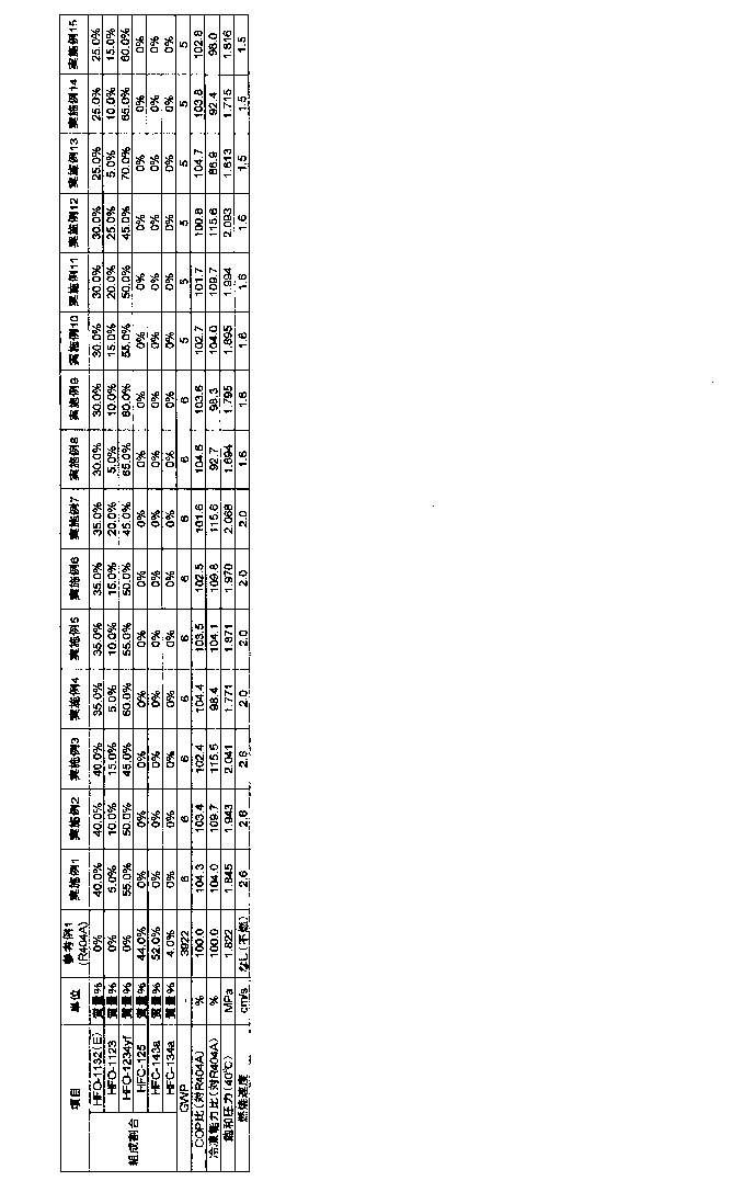


冷媒Cは、一つの態様において、HFO-1132(E)及びHFO-1234yfを含有し、HFO-1132(E)及びHFO-1234yfの全質量に対して、HFO-1132(E)の含有割合は35.0~65.0質量%であり、HFO-1234yfの含有割合は65.0~35.0質量%である。この冷媒を「冷媒C1」ということがある。
冷媒C1は、上述の構成を有することによって、(1)GWPが十分小さいこと(100以下)、(2)R404Aと同等又はそれ以上のCOPを有すること、及び(3)R404Aと同等又はそれ以上の冷凍能力を有すること、という諸特性を有する。
また、冷媒C1において、HFO-1132(E)及びHFO-1234yfの全質量に対する、HFO-1132(E)の含有割合が65.0質量%以下であることにより、冷媒C1の冷凍サイクルにおける飽和温度40℃の飽和圧力を好適な範囲(特に2.10Mpa以下)に維持することができる。
圧縮比=凝縮圧力(Mpa)/蒸発圧力(Mpa)
本開示の冷媒C1が使用される冷凍サイクルにおいて、蒸発温度は好ましくは-7.5℃以下、より好ましくは-10℃以下、更に好ましくは-35℃以下である。
更にこの場合、冷媒C1は、飽和温度40℃における飽和圧力が、1.75MPa以上2.00MPa以下となるため、市販のR404A用冷凍装置に対して大きな設計変更なく適用することができる。
本開示の組成物に含まれる冷媒は、一つの態様において、HFO-1132(E)及びHFO-1234yfを含有し、HFO-1132(E)及びHFO-1234yfの全質量に対して、HFO-1132(E)の含有割合が40.5~49.2質量%であり、HFO-1234yfの含有割合が59.5~50.8質量%である。この冷媒を「冷媒C2」ということがある。
更にこの場合、冷媒C2は、飽和温度40℃の飽和圧力が、1.76MPa以上1.88MPa以下となり、市販のR404A用冷凍装置に対して大きな設計変更なく適用することができる。
本開示の組成物に含まれる冷媒は、一つの態様において、HFO-1132(E)及びHFO-1234yfを含有し、HFO-1132(E)及びHFO-1234yfの全質量に対して、HFO-1132(E)の含有割合が31.1~39.8質量%であり、HFO-1234yfの含有割合が68.9~60.2質量%である。この冷媒を「冷媒C3」ということがある。
また、冷媒C3において、HFO-1132(E)及びHFO-1234yfの全質量に対する、HFO-1132(E)の含有割合が39.8質量%以下であることにより、冷媒C3の冷凍サイクルにおける吐出温度を90℃以下に維持し、R134a用冷凍装置の部材の寿命を長く確保することができる。
冷媒C3は、このような構成を有することによって、(1)GWPが十分小さいこと(100以下)、(2)R134aと同等程度のCOPを有すること、(3)R134aと比べて150%以上の冷凍能力を有すること、及び(4)吐出温度が90.0℃以下であることという、諸特性を有する。
本開示の組成物に含まれる冷媒は、一つの態様において、HFO-1132(E)及びHFO-1234yfを含有し、HFO-1132(E)及びHFO-1234yfの全質量に対して、HFO-1132(E)の含有割合が21.0~28.4質量%であり、HFO-1234yfの含有割合が79.0~71.6質量%である。この冷媒を「冷媒C4」ということがある。
本開示の組成物に含まれる冷媒は、一つの態様において、HFO-1132(E)及びHFO-1234yfを含有し、HFO-1132(E)及びHFO-1234yfの全質量に対して、HFO-1132(E)の含有割合は12.1~72.0質量%であり、HFO-1234yfの含有割合は87.9~28.0質量%である。この冷媒を「冷媒C5」ということがある。
以下に、実施例を挙げて更に詳細に説明する。ただし、本開示は、これらの実施例に限定されるものではない。
実施例1-1~1-13、比較例1-1~1-2及び参考例1-1(R404A)に示される混合冷媒のGWPは、IPCC第4次報告書の値に基づいて評価した。
蒸発温度 -50℃
凝縮温度 40℃
過熱温度 20K
過冷却温度 0K
圧縮機効率 70%
「蒸発温度-50℃」とは、冷凍装置が備える蒸発器における混合冷媒の蒸発温度が-50℃であることを意味する。また、「凝縮温度40℃」とは、冷凍装置が備える凝縮器における混合冷媒の凝縮温度が40℃であることを意味する。
COP=(冷凍能力又は暖房能力)/消費電力量
圧縮比=凝縮圧力(Mpa)/蒸発圧力(Mpa)
試験容器:280mmφ球形(内容積:12リットル)
試験温度:60℃±3℃
圧力:101.3kPa±0.7kPa
水分:乾燥空気1gにつき0.0088g±0.0005g(23℃における相対湿度50%の水分量)冷媒組成物/空気混合比:1vol.%刻み±0.2vol.%
冷媒組成物混合:±0.1質量%
点火方法:交流放電、電圧15kV、電流30mA、ネオン変圧器
電極間隔:6.4mm(1/4inch)
スパーク:0.4秒±0.05秒
判定基準:
・着火点を中心に90度より大きく火炎が広がった場合=火炎伝播あり(可燃)
・着火点を中心に90度以下の火炎の広がりだった場合=火炎伝播なし(不燃)

実施例1-14~1-26、比較例1-3~1-4及び参考例1-2(R404A)に示される混合冷媒のGWPは、IPCC第4次報告書の値に基づいて評価した。
蒸発温度 -35℃
凝縮温度 40℃
過熱温度 20K
過冷却温度 0K
圧縮機効率 70%
上記用語の意味は、試験例1-1と同様である。
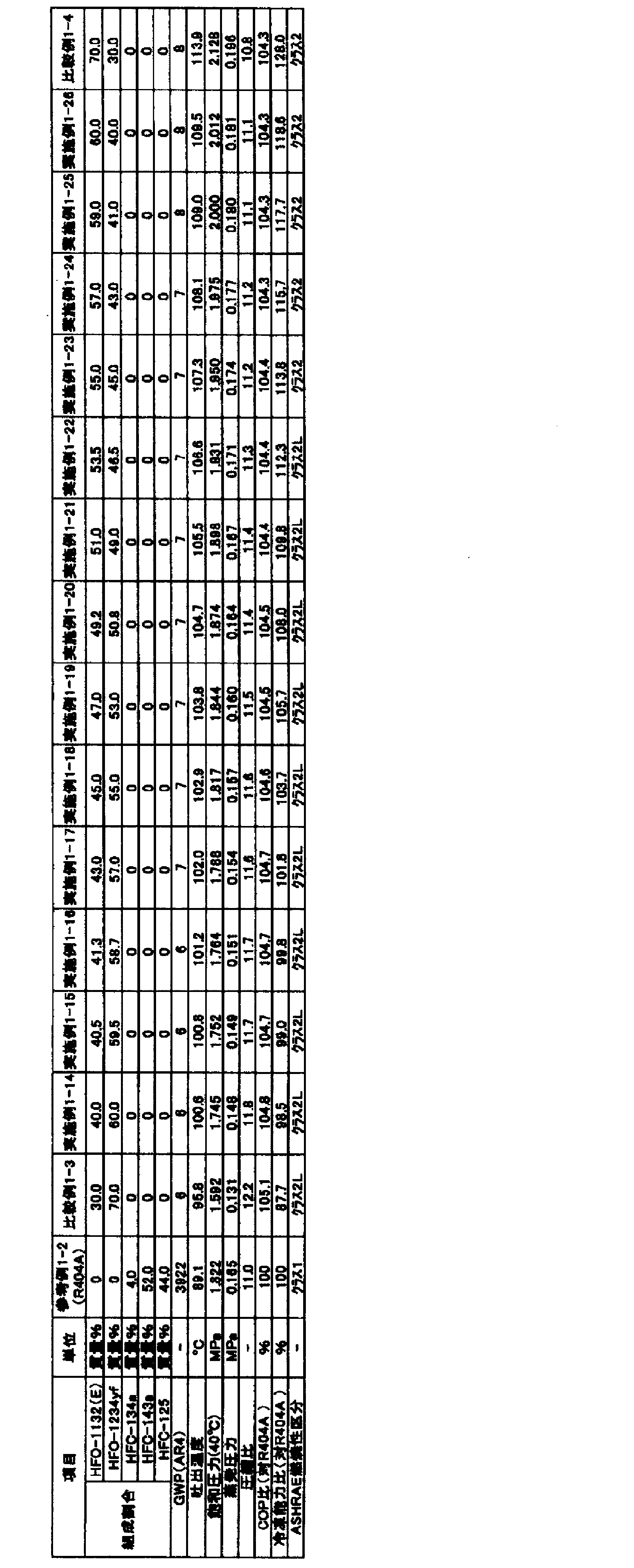
実施例1-27~1-39、比較例1-5~1-6及び参考例1-3(R404A)に示される混合冷媒のGWPは、IPCC第4次報告書の値に基づいて評価した。
蒸発温度 -10℃
凝縮温度 40℃
過熱温度 20K
過冷却温度 0K
圧縮機効率 70%
上記用語の意味は、試験例1-1と同様である。

比較例1-7~1-21及び参考例1-4(R404A)に示される混合冷媒のGWPは、IPCC第4次報告書の値に基づいて評価した。
蒸発温度 -80℃
凝縮温度 40℃
過熱温度 20K
過冷却温度 0K
圧縮機効率 70%
上記用語の意味は、試験例1-1と同様である。
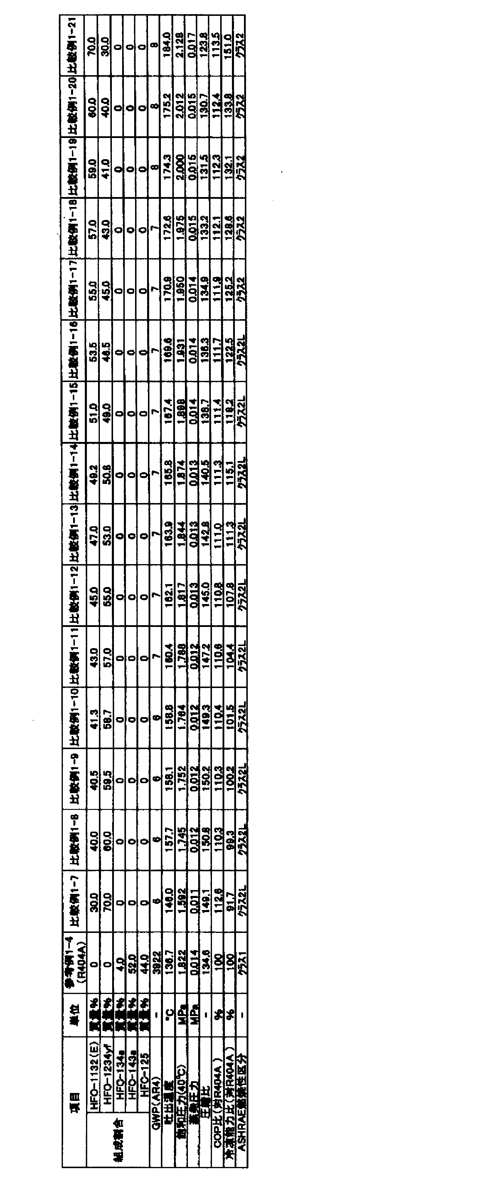
比較例1-22~1-36及び参考例1-5(R404A)に示される混合冷媒のGWPは、IPCC第4次報告書の値に基づいて評価した。
蒸発温度 10℃
凝縮温度 40℃
過熱温度 20K
過冷却温度 0K
圧縮機効率 70%
上記用語の意味は、試験例1-1と同様である。

実施例2-1~2-6、比較例2-1~2-9及び参考例2-1(R404A)に示される混合冷媒のGWPは、IPCC第4次報告書の値に基づいて評価した。
蒸発温度 -50℃
凝縮温度 40℃
過熱温度 20K
過冷却温度 0K
圧縮機効率 70%
「蒸発温度-50℃」とは、冷凍装置が備える蒸発器における混合冷媒の蒸発温度が-50℃であることを意味する。また、「凝縮温度40℃」とは、冷凍装置が備える凝縮器における混合冷媒の凝縮温度が40℃であることを意味する。
COP=(冷凍能力又は暖房能力)/消費電力量
圧縮比=凝縮圧力(Mpa)/蒸発圧力(Mpa)
試験容器:280mmφ球形(内容積:12リットル)
試験温度:60℃±3℃
圧力:101.3kPa±0.7kPa
水分:乾燥空気1gにつき0.0088g±0.0005g(23℃における相対湿度50%の水分量)冷媒組成物/空気混合比:1vol.%刻み±0.2vol.%
冷媒組成物混合:±0.1質量%
点火方法:交流放電、電圧15kV、電流30mA、ネオン変圧器
電極間隔:6.4mm(1/4inch)
スパーク:0.4秒±0.05秒
判定基準:
・着火点を中心に90度より大きく火炎が広がった場合=火炎伝播あり(可燃)
・着火点を中心に90度以下の火炎の広がりだった場合=火炎伝播なし(不燃)

実施例2-7~2-12、比較例2-10~2-18及び参考例2-2(R404A)に示される混合冷媒のGWPは、IPCC第4次報告書の値に基づいて評価した。
蒸発温度 -35℃
凝縮温度 40℃
過熱温度 20K
過冷却温度 0K
圧縮機効率 70%
上記用語の意味は、試験例2-1と同様である。

実施例2-13~2-18、比較例2-19~2-27及び参考例2-3(R404A)に示される混合冷媒のGWPは、IPCC第4次報告書の値に基づいて評価した。
蒸発温度 -10℃
凝縮温度 40℃
過熱温度 20K
過冷却温度 0K
圧縮機効率 70%
上記用語の意味は、試験例2-1と同様である。
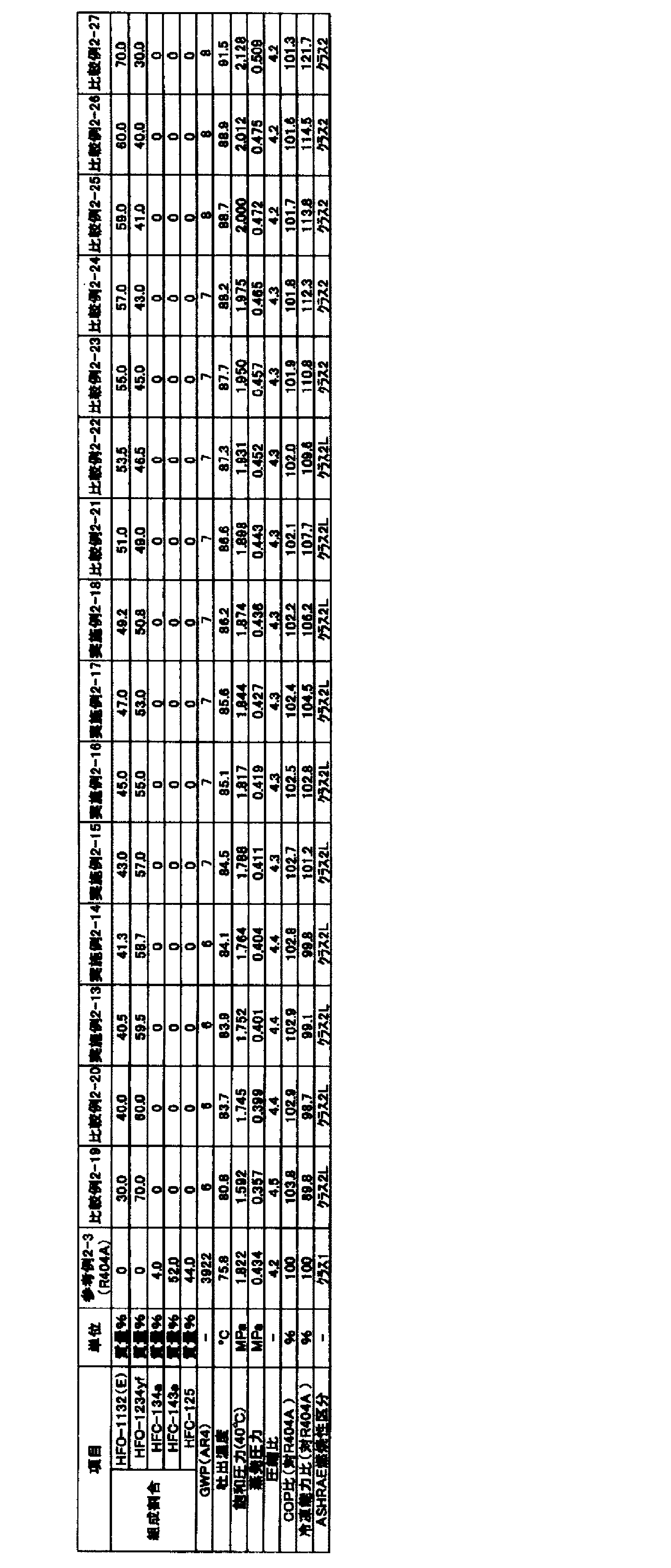
実施例2-19~2-24、比較例2-28~2-36及び参考例2-4(R404A)に示される混合冷媒のGWPは、IPCC第4次報告書の値に基づいて評価した。
蒸発温度 -80℃
凝縮温度 40℃
過熱温度 20K
過冷却温度 0K
圧縮機効率 70%
上記用語の意味は、試験例2-1と同様である。

実施例2-25~2-30、比較例2-37~2-45及び参考例2-5(R404A)に示される混合冷媒のGWPは、IPCC第4次報告書の値に基づいて評価した。
蒸発温度 10℃
凝縮温度 40℃
過熱温度 20K
過冷却温度 0K
圧縮機効率 70%
上記用語の意味は、試験例2-1と同様である。
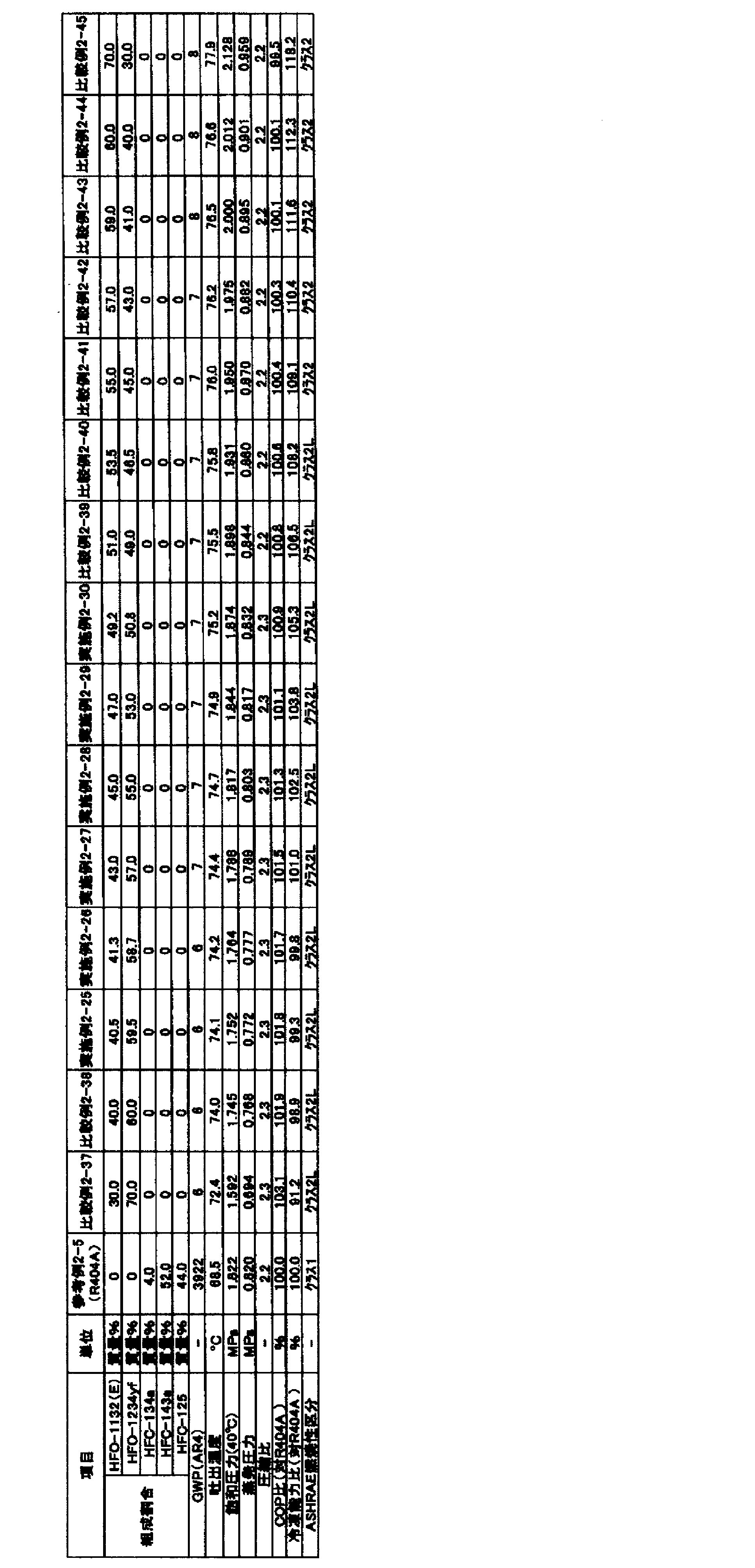
実施例3-1~3-5、比較例3-1~3-5、参考例3-1(R134a)及び参考例3-2(R404A)に示される混合冷媒のGWPは、IPCC第4次報告書の値に基づいて評価した。
蒸発温度 -10℃
凝縮温度 45℃
過熱温度 20K
過冷却温度 0K
圧縮機効率 70%
「蒸発温度-10℃」とは、冷凍装置が備える蒸発器における混合冷媒の蒸発温度が-10℃であることを意味する。また、「凝縮温度45℃」とは、冷凍装置が備える凝縮器における混合冷媒の凝縮温度が45℃であることを意味する。
COP=(冷凍能力又は暖房能力)/消費電力量
試験容器:280mmφ球形(内容積:12リットル)
試験温度:60℃±3℃
圧力:101.3kPa±0.7kPa
水分:乾燥空気1gにつき0.0088g±0.0005g(23℃における相対湿度50%の水分量)冷媒組成物/空気混合比:1vol.%刻み±0.2vol.%
冷媒組成物混合:±0.1質量%
点火方法:交流放電、電圧15kV、電流30mA、ネオン変圧器
電極間隔:6.4mm(1/4inch)
スパーク:0.4秒±0.05秒
判定基準:
・着火点を中心に90度より大きく火炎が広がった場合=火炎伝播あり(可燃)
・着火点を中心に90度以下の火炎の広がりだった場合=火炎伝播なし(不燃)

実施例4-1~4-7及び比較例4-1~4-5に示される混合冷媒のGWPは、IPCC第4次報告書の値に基づいて評価した。
蒸発温度 5℃
凝縮温度 45℃
過熱温度 5K
過冷却温度 5K
圧縮機効率 70%
「蒸発温度 5℃」とは、冷凍装置が備える蒸発器における混合冷媒の蒸発温度が5℃であることを意味する。また、「凝縮温度 45℃」とは、冷凍装置が備える凝縮器における混合冷媒の凝縮温度が45℃であることを意味する。
COP=(冷凍能力又は暖房能力)/消費電力量
試験容器:280mmφ球形(内容積:12リットル)
試験温度:60℃±3℃
圧力:101.3kPa±0.7kPa
水分:乾燥空気1gにつき0.0088g±0.0005g(23℃における相対湿度50%の水分量)
冷媒組成物/空気混合比:1vol.%刻み±0.2vol.%
冷媒組成物混合:±0.1質量%
点火方法:交流放電、電圧15kV、電流30mA、ネオン変圧器
電極間隔:6.4mm(1/4inch)
スパーク:0.4秒±0.05秒
判定基準:
・着火点を中心に90度より大きく火炎が広がった場合=火炎伝播あり(可燃)
・着火点を中心に90度以下の火炎の広がりだった場合=火炎伝播なし(不燃)

実施例5-1~5-13、比較例5-1~5-3及び参考例5-1(R134a)に示される混合冷媒のGWPは、IPCC第4次報告書の値に基づいて評価した。
蒸発温度 -30℃
凝縮温度 30℃
過熱温度 5K
過冷却温度 5K
圧縮機効率 70%
「蒸発温度 -30℃」とは、冷凍装置が備える蒸発器における混合冷媒の蒸発温度が-30℃であることを意味する。また、「凝縮温度 30℃」とは、冷凍装置が備える凝縮器における混合冷媒の凝縮温度が30℃であることを意味する。
COP=(冷凍能力又は暖房能力)/消費電力量
暖房使用時の消費電力量=暖房能力/暖房COP
蒸発温度 -30℃
凝縮温度 30℃
過熱温度 5K
過冷却温度 5K
圧縮機効率 70%
走行可能距離=(電池容量)/(動力の消費電力量+暖房での消費電力量)
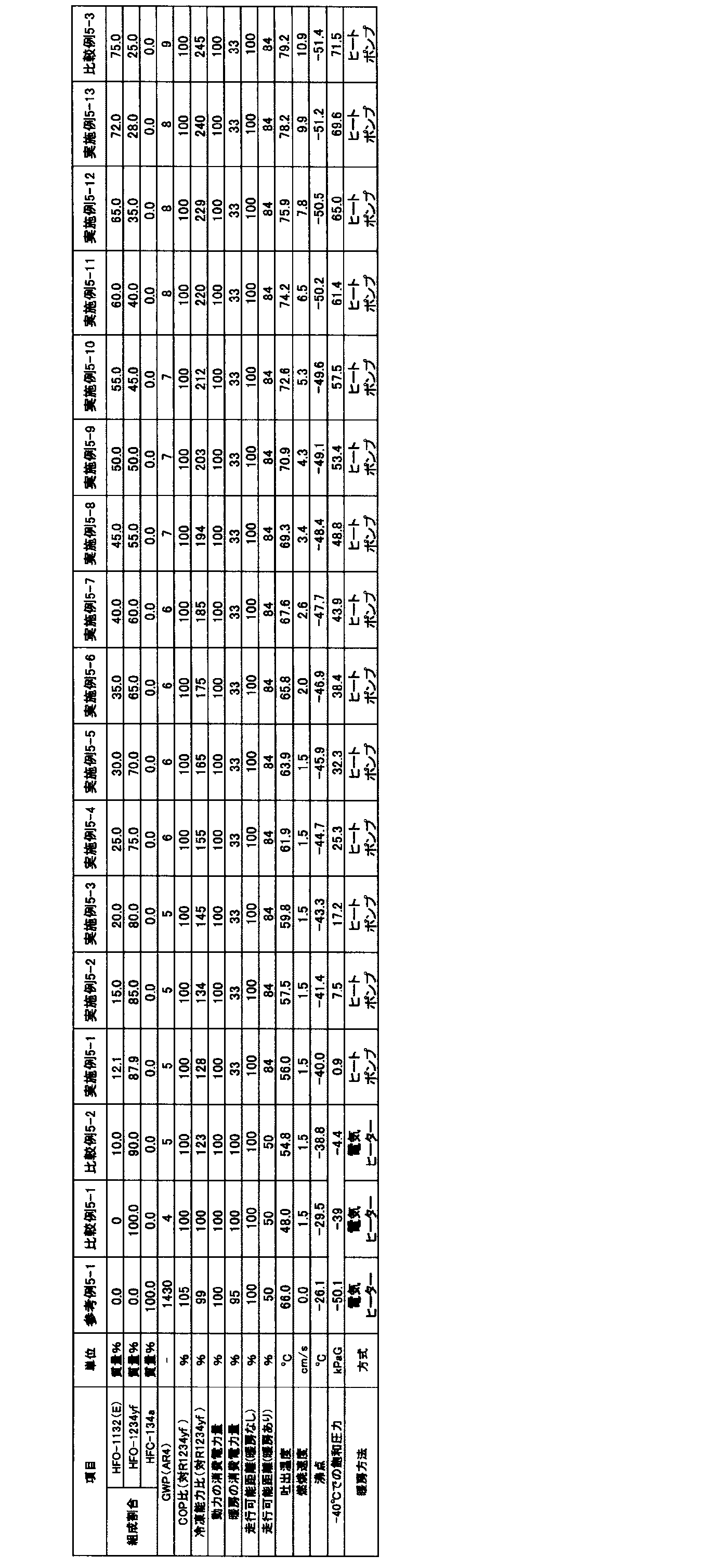
本開示の冷媒Dは、ジフルオロメタン(HFC-32)、2,3,3,3-テトラフルオロプロペン(HFO-1234yf)、並びに、1,1-ジフルオロエチレン(HFO-1132a)及びテトラフルオロエチレン(FO-1114)の少なくとも一種を含有することを特徴とする。そして、上記特徴を有する本開示の冷媒Dは、R404A及び/又はR410Aと同等以上の成績係数(COP)と冷凍能力(Cap)とを有し、GWPが十分に小さいという三種の性能を兼ね備えている。
点R(21.80, 3.95, 74.25)、
点S(21.80, 3.05, 75.15)、及び
点T(20.95, 75.30, 3.75)、
の3点をそれぞれ結ぶ線分RS、ST及びTRで囲まれる三角形の範囲内又は前記線分上にあることを特徴とする(図2Dの拡大図中、線分RS、ST及びTRで囲まれる三角形の範囲内又は前記線分上)。
前記冷媒において、HFC-32、HFO-1132a及びHFO-1234yfの、これらの総和を基準とする質量%をそれぞれx、y及びzとするとき、HFC-32、HFO-1132a及びHFO-1234yfの総和が100質量%となる3成分組成図において、座標(x, y, z)が、
点L(74.0, 19.9, 6.1)、
点F(49.1, 25.9, 25.0)、
点G(0.0, 48.6, 51.4)、
点O(0.0, 0.0, 100)、及び
点B(73.9, 0.0, 26.1)、
の5点をそれぞれ結ぶ線分LF、FG、GO、OB及びBLで囲まれる図形の範囲内又は前記線分上(但し、線分GO及びOB上を除く)にあり、
前記線分LFは、
座標(y=0.0021x2-0.4975x+45.264)で表わされ、
前記線分FGは、
座標(y=0.0031x2-0.6144x+48.6)で表わされ、且つ、
前記線分GO、OB及びBLが直線であることを特徴とする。
前記冷媒において、HFC-32、HFO-1132a及びHFO-1234yfの、これらの総和を基準とする質量%をそれぞれx、y及びzとするとき、HFC-32、HFO-1132a及びHFO-1234yfの総和が100質量%となる3成分組成図において、座標(x, y, z)が、
点P(59.1, 23.2, 17.7)、
点F(49.1, 25.9, 25.0)、
点G(0.0, 48.6, 51.4)、
点O(0.0, 0.0, 100)及び
点B’(59.0, 0.0, 40.2)、
の5点をそれぞれ結ぶ線分PF、FG、GO、OB’及びB’Pで囲まれる図形の範囲内又は前記線分上(但し、線分GO及びOB’上を除く)にあり、
前記線分PFは、
座標(y=0.0021x2-0.4975x+45.264)で表わされ、
前記線分FGは、
座標(y=0.0031x2-0.6144x+48.6)で表わされ、且つ、
前記線分GO、OB’及びB’Pが直線であることを特徴とする。
前記冷媒において、HFC-32、HFO-1132a及びHFO-1234yfの、これらの総和を基準とする質量%をそれぞれx、y及びzとするとき、HFC-32、HFO-1132a及びHFO-1234yfの総和が100質量%となる3成分組成図において、座標(x, y, z)が、
点M(74.0, 19.5, 6.5)、
点I(62.9, 15.5, 21.6)、
点J(33.5, 0.0, 66.5)、及び
点B(73.9, 0.0, 26.1)、
の4点をそれぞれ結ぶ線分MI、IJ、JB及びBMで囲まれる図形の範囲内又は前記線分上(但し、線分JB上を除く)にあり、
前記線分MIは、
座標(y=0.006x2+1.1837x-35.264)で表わされ、
前記線分IJは、
座標(y=0.0083x2-0.2719x-0.1953)で表わされ、且つ、
前記線分JB及びBMが直線であることを特徴とする。
前記冷媒において、HFC-32、HFO-1132a及びHFO-1234yfの、これらの総和を基準とする質量%をそれぞれx、y及びzとするとき、HFC-32、HFO-1132a及びHFO-1234yfの総和が100質量%となる3成分組成図において、座標(x, y, z)が、
点Q(59.1, 12.7, 28.2)、
点J(33.5, 0.0, 66.5)、及び
点B’(59.0, 0.0, 40.2)、
の3点をそれぞれ結ぶ線分QJ、JB’及びB’Qで囲まれる図形の範囲内又は前記線分上(但し、線分JB’上を除く)にあり、
前記線分QJは、
座標(y=0.0083x2-0.2719x-0.1953)で表わされ、且つ、
前記線分JB’及びB’Qがで直線であることを特徴とする。
前記冷媒において、HFC-32、HFO-1132a及びHFO-1234yfの、これらの総和を基準とする質量%をそれぞれx、y及びzとするとき、HFC-32、HFO-1132a及びHFO-1234yfの総和が100質量%となる3成分組成図において、座標(x, y, z)が、
点Q(59.1, 12.7, 28.2)、
点U(59.0, 5.5, 35.5)、及び
点V(52.5, 8.4, 39.1)、
の3点をそれぞれ結ぶ線分QU、UV及びVQで囲まれる図形の範囲内又は前記線分上にあり、
前記線分VQは、
座標(y=0.0083x2-0.2719x-0.1953)で表わされ、且つ、
前記線分UVは、
座標(y=0.0026x2-0.7385x+39.946)で表わされ
前記線分QUが直線であることを特徴とする。
本開示の冷媒Dは、上記の特性や効果を損なわない範囲内で、HFC-32、HFO-1234yf、並びに、HFO-1132a及びFO-1114の少なくとも一種に加えて、更に他の追加的な冷媒を含有する混合冷媒であってもよい。この場合、HFC-32、HFO-1234yf、並びに、HFO-1132a及びFO-1114の少なくとも一種の合計量が、本開示の冷媒全体に対して、99.5質量%以上100質量%未満であることが好ましく、99.75質量%以上100質量%未満であることがより好ましく、99.9質量%%以上100質量%未満であることが更に好ましい。 上記追加的な冷媒としては、特に限定されず、この分野で広く使用されている公知の冷媒の中から幅広く選択できる。上記混合冷媒は、上記追加的な冷媒を単独で含んでいてもよいし、上記追加的な冷媒を2種以上を含んでいてもよい。
以下に、実施例を挙げて更に詳細に説明する。ただし、本開示は、これらの実施例に限定されるものではない。
実施例17~87及び比較例2~18(第3形態~第7形態の冷媒Dに対応)
各実施例及び比較例に示される混合冷媒のGWP、並びに、R404A(R125/143a/R134a=44/52/4重量%)、R410A(R32/R125=50/50重量%)のGWPは、IPCC(Intergovernmental Panel on Climate Change)第4次報告書の値に基づいて評価した。
蒸発温度 -40℃
凝縮温度 40℃
過熱温度 20K
過冷却温度 0K
圧縮機効率 70%
実施例17~87及び比較例2~18(第3形態~第7形態の冷媒Dに対応)は下記条件で混合冷媒の冷凍サイクル理論計算を実施することにより求めた。
蒸発温度 5℃
凝縮温度 45℃
過熱温度 5K
過冷却温度 5K
圧縮機効率 70%
COP=(冷凍能力又は暖房能力)/消費電力量


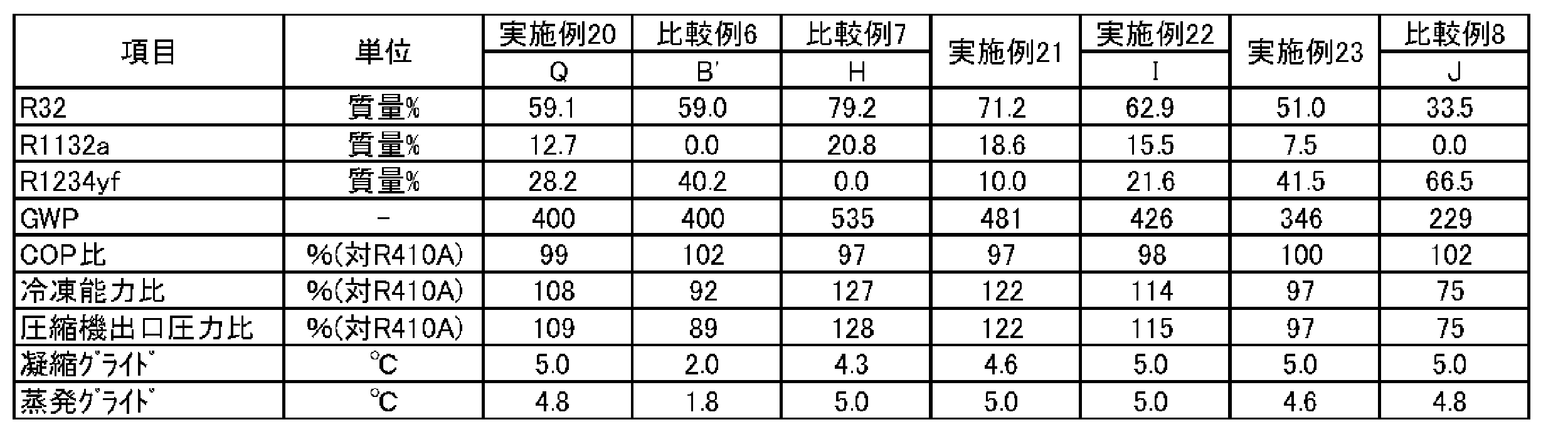
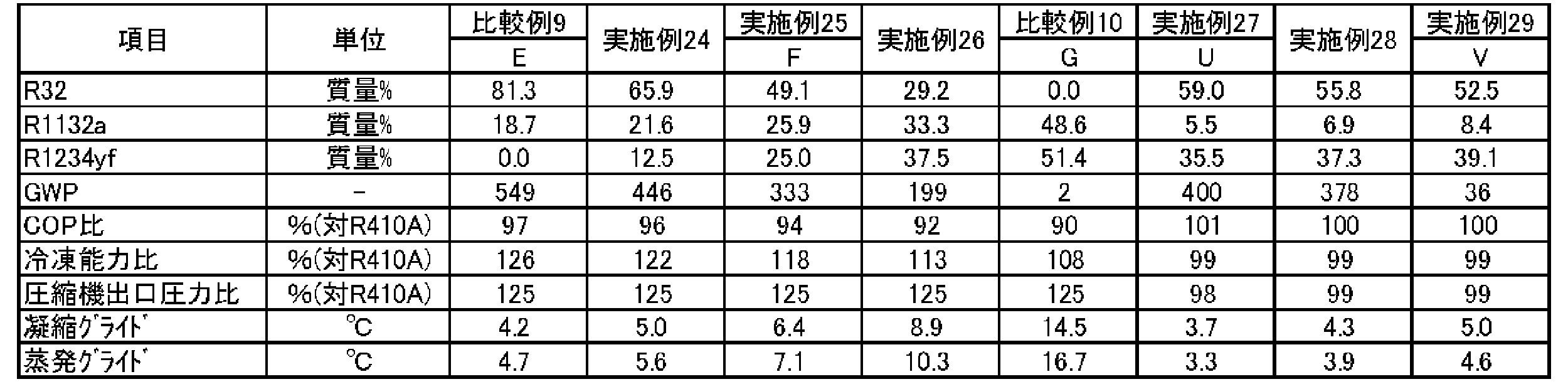


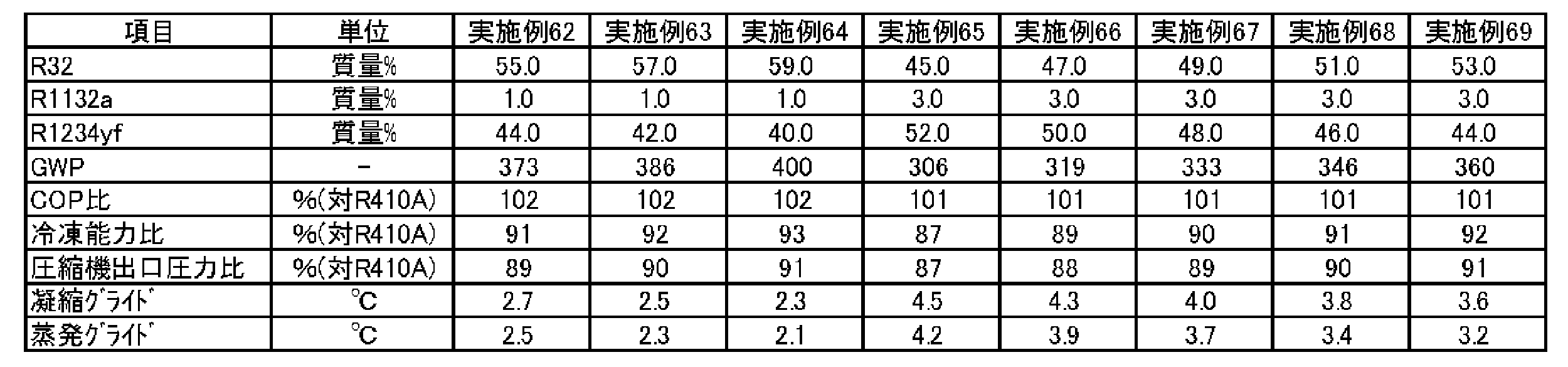
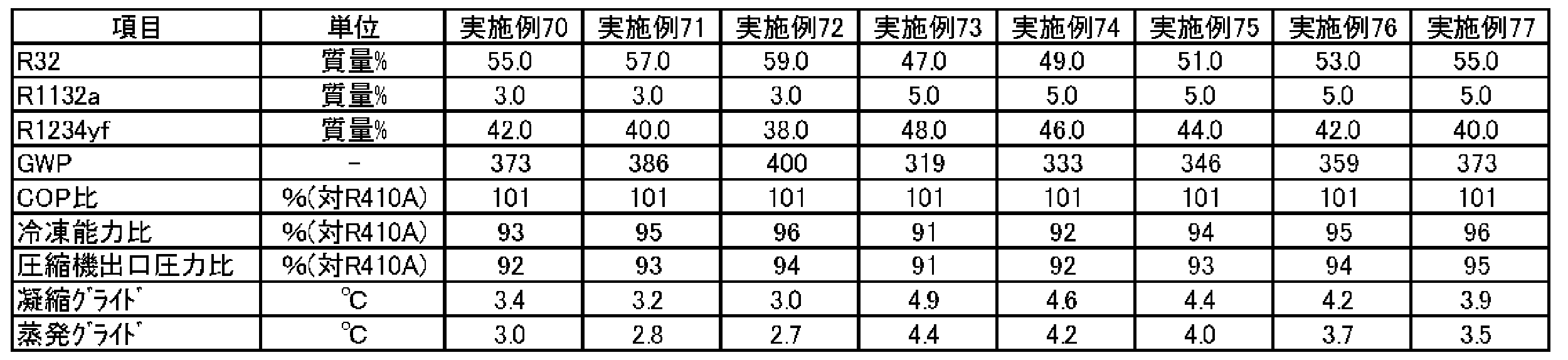


本開示の冷媒Eは、R32、CO2、R125、R134a及びR1234yfを含有する混合冷媒である。
要件1-1-1)
43.8≧x≧41、かつ0.5≧r≧0.25であるとき、
点A(-0.6902x+43.307, 100-a-x, 0.0)、
点Or=0.25~0.5((-2.2857x+87.314)r2+(1.7143x-55.886)r+(-0.9643x+55.336), (2.2857x-112.91)r2+(-1.7143x+104.69)r+(-0.25x+11.05), 100-a-b-x)、
点Dr=0.25~0.5(0.0, -28.8r2+54.0r+(-x+49.9), 100-b-x)及び
点Q(0.0, 100-x, 0.0)
を結ぶ線分で囲まれる四角形の範囲内又は該線分上にあるか(ただし、線分Dr=0.25~0.5Q及びQA上の点は除く)、又は
要件1-1-2)
43.8≧x≧41、かつ1.0≧r≧0.5であるとき、
点A(-0.6902x+43.307, 100-a-c, 0.0)、
点Or=0.5~1.0((-0.2857x+8.5143)r2+(0.5x-10.9)+(-0.8571x+52.543), (-0.2857x+4.5143)r2+(0.5x+0.9)r+(-0.7143x+33.586), 100-a-b-x)、
点Dr=0.5~1.0(0.0, (-0.5714x+12.229)r2+(0.8571x-0.3429)r+(-1.2857x+66.814), 100-b-x)及び
点Q(0.0, 100-x, 0.0)
を結ぶ線分で囲まれる四角形の範囲内又は該線分上にあるか(ただし、線分Dr=0.5~1.0Q及びQA上の点は除く)、又は
要件1-2-1)
46.5≧x≧43.8、かつ0.5≧r≧0.25であるとき、
点A(-0.6902x+43.307, 100-a-x, 0.0)、
点Or=0.25~0.5((1.1852x-64.711)r2+(-0.7407x+51.644)r+(-0.5556x+37.433), (-2.3704x+91.022)r2+(2.0741x-61.244)r+(-0.963x+42.278), 100-a-b-x)、
点Dr=0.25~0.5(0.0, -28.8r2+54.0r+(-x+49.9), 100-b-x)及び
点Q(0.0, 100-x, 0.0)
を結ぶ線分で囲まれる四角形の範囲内又は該線分上にあるか(ただし、線分Dr=0.25~0.5Q及びQA上の点は除く)、又は
要件1-2-2)
46.5≧x≧43、かつ1.0≧r≧0.5であるとき、
点A(-0.6902x+43.307, 100-a-x, 0.0)、
点Or=0.5~1.0((0.2963x-16.978)r2+(-0.3704x+27.222)r+(-0.5185x+37.711), -8.0r2+22.8r+(-0.5185x+25.011), 100-a-b-x)、
点Dr=0.5~1.0(0.0, -12.8r2+37.2r+(-x+54.3), 100-b-x)及び
点Q(0.0, 100-x, 0.0)
を結ぶ線分で囲まれる四角形の範囲内又は該線分上にあるか(ただし、線分Dr=0.5~1.0Q及びQA上の点は除く)、
要件1-3-1)
50≧x≧46.5、かつ0.5≧r≧0.25であるとき、
点A(-0.6902x+43.307, 100-a-x, 0.0)、
点Or=0.25~0.5(-9.6r2+17.2r+(-0.6571x+42.157), -19.2r2+(0.2286x+24.571)r+(-0.6286x+26.729), 100-a-b-x)、
点Dr=0.25~0.5(0.0, (0.9143x-71.314)r2+(-0.5714x+80.571)+(-0.9143x+45.914), 100-b-x)及び
点Q(0.0, 100-x, 0.0)
を結ぶ線分で囲まれる四角形の範囲内又は該線分上にあるか(ただし、線分Dr=0.25~0.5Q及びQA上の点は除く)、又は
要件1-3-2)
50≧x≧46.5、かつ1.0≧r≧0.5であるとき、
点A(-0.6902x+43.307, 100-a-x, 0.0)、
点Or=0.5~1.0((-0.2286x+7.4286)r2+(0.4x-8.6)r+(-0.8x+50.8), (0.2286x-18.629)r2+(-0.2857x+36.086)r+(-0.4286x+20.829), 100-a-b-x)、
点Dr=0.5~1.0(0.0, (0.2286x-23.429)r2+(-0.4x+55.8)r+(-0.8286x+46.329), 100-b-x)及び
点Q(0.0, 100-x, 0.0)
を結ぶ線分で囲まれる四角形の範囲内又は該線分上にある(ただし、線分Dr=0.5~1.0Q及びQA上の点は除く)。
43.8≧x≧41、かつ0.5≧r≧0.25であるとき、
点Fr=0.25~0.5(0.0, (-1.1429x+37.257)r2+(1.2857x-38.714)r-(-1.7143x+106.89), 100-b-x)、
点Pr=0.25~0.5((-1.1429x+34.057)r2+(1.0x-21.0)r+(-0.4643x+27.636), (2.2857x-119.31)r2+(-2.0x+122.0)r+(-0.3929x+19.907), 100-a-b-x)及び
点Dr=0.25~0.5(0.0, -28.8r2+54.0r+(-x+49.9), 100-b-x)
を結ぶ線分で囲まれる三角形の範囲内又は該線分上にあるか(ただし、線分Dr=0.25~0.5Fr=0.25~0.5上の点は除く)、又は
2-1-2)43.8≧x≧41、かつ1.0≧r≧0.5であるとき、
点Fr=0.5~1.0(0.0, (3.7143x-159.49)r2+(-5.0714x+222.53)r+(0.25x+25.45), 100-b-x)、
点Pr=0.5~1.0((3.4286x-138.17)r2+(-5.4286x+203.57)+(1.6071x-41.593), (-2.8571x+106.74)r2+(4.5714x-143.63)r+(-2.3929x+96.027), 100-a-b-x)及び
点Dr=0.5~1.0(0.0, (-0.5714x+12.229)r2+(0.8571x-0.3429)r+(-1.2857x+66.814), 100-b-x)
を結ぶ線分で囲まれる三角形の範囲内又は該線分上にあるか(ただし、線分Dr=0.5~1.0Fr=0.5~1.0上の点は除く)、又は
要件2-2-1)46.5≧x≧43、かつ0.5≧r≧0.25であるとき、
点Fr=0.25~0.5(0.0, (9.4815x-428.09)r2+(-7.1111x+329.07)r+(-0.2593x+43.156), 100-b-x)、
点Pr=0.25~0.5((-8.2963x+347.38)r2+(4.8889x-191.33)r+(-0.963x+49.478), (7.1111x-330.67)r2+(-4.1481x+216.09)r+(-0.2593x+14.056), 100-a-b-x)及び
点Dr=0.25~0.5(0.0, -28.8r2+54.0r+(-x+49.9), 100-b-x)
を結ぶ線分で囲まれる三角形の範囲内又は該線分上にあるか(ただし、線分Dr=0.25~0.5Fr=0.25~0.5上の点は除く)、又は
要件2-2-2)46.5≧x≧43、かつ1.0≧r≧0.5であるとき、
点Fr=0.5~1.0(0.0, (-4.7407x+210.84)r2+(6.963x-304.58)r+(-3.7407x+200.24), 100-b-x)、
点Pr=0.5~1.0((0.2963x-0.9778)r2+(0.2222x-43.933)r+(-0.7778x+62.867), (-0.2963x-5.4222)r2+(-0.0741x+59.844)r+(-0.4444x+10.867), 100-a-b-x)及び
点Dr=0.5~1.0(0.0, -12.8r2+37.2r+(-x+54.3), 100-b-x)
を結ぶ線分で囲まれる三角形の範囲内又は該線分上にあるか(ただし、線分Dr=0.5~1.0Fr=0.5~1.0上の点は除く)、又は
要件2-3-1)50≧x≧46.5、かつ0.37≧r≧0.25であるとき、
点Fr=0.25~0.37(0.0, (-35.714x+1744.0)r2+(23.333x-1128.3)r+(-5.144x+276.32), 100-b-x)、
点Pr=0.25~0.37((11.905x-595.24)r2+(-7.6189x+392.61)r+(0.9322x-39.027), (-27.778x+1305.6)r2+(17.46x-796.35)r+(-3.5147x+166.48),100-a-b-x)及び
点Dr=0.25~0.37(0.0, (0.9143x-71.314)r2+(-0.5714x+80.571)+(-0.9143x+45.914), 100-b-x)
を結ぶ線分で囲まれる三角形の範囲内又は該線分上にあるか(ただし、線分Dr=0.25~0.37Fr=0.25~0.37上の点は除く)、又は
要件2-3-2)50≧x≧46.5、かつ1.0≧r≧0.5であるとき、
点Fr=0.5~1.0(0.0, (2.2857x-115.89)r2+(-3.0857x+162.69)r+(-0.3714x+43.571), 100-b-x)、
点Pr=0.5~1.0((-3.2x+161.6)r2+(4.4571x-240.86)r+(-2.0857x+123.69), (2.5143x-136.11)r2+(-3.3714x+213.17)r+(0.5429x-35.043), 100-a-b-x)及び
点Dr=0.5~1.0(0.0, (0.2286x-23.429)r2+(-0.4x+55.8)r+(-0.8286x+46.329), 100-b-x)
を結ぶ線分で囲まれる三角形の範囲内又は該線分上にある(ただし、線分Dr=0.5~1.0Fr=0.5~1.0上の点は除く)。
以下に、実施例を挙げてさらに詳細に説明する。ただし、本開示は、これらの実施例に限定されるものではない。
R32、CO2、R125、R134a及びR1234yfのみからなる混合冷媒の組成は、以下のようにして表わす。すなわち、R32、CO2、R125、R134a及びR1234yfの総和を基準とする、R32の質量%をa、CO2の質量%をb、R125の質量%をc1、R134aの質量%をc2、R125及びR134aの合計の質量%をc、R1234yfの質量%をxとし、c1/(c1+c2)をrとする場合、R32が(100-x)質量%の点と、CO2が(100-x)質量%の点と、R125及びR134aの合計が(100-x)質量%の点とを頂点とする3成分組成図における座標(a,b,c)により、この混合冷媒の組成を特定する。
2元混合冷媒の不燃限界は、ASTM E681-2009に基づく燃焼試験の測定装置(図2E)及び測定方法に基づいて求めた。
試験容器:280 mmφ球形(内容積:12リットル)
試験温度: 60℃±3℃
圧力 :101.3 kPa±0.7 kPa
水分 :乾燥空気1 gにつき0.0088 g±0.0005 g
2元冷媒組成物/空気混合比:1 vol.%刻み±0.2 vol.%
2元冷媒組成物混合: ±0.1 質量%
点火方法:交流放電、電圧15kV、電流30mA、ネオン変圧器
電極間隔:6.4 mm (1/4 inch)
スパーク:0.4 秒 ±0.05 秒
判定基準:
・着火点を中心に90度より火炎が広がった場合 = 燃焼(伝播)
・着火点を中心に90度以下の火炎の広がりだった場合= 火炎伝播なし(不燃)
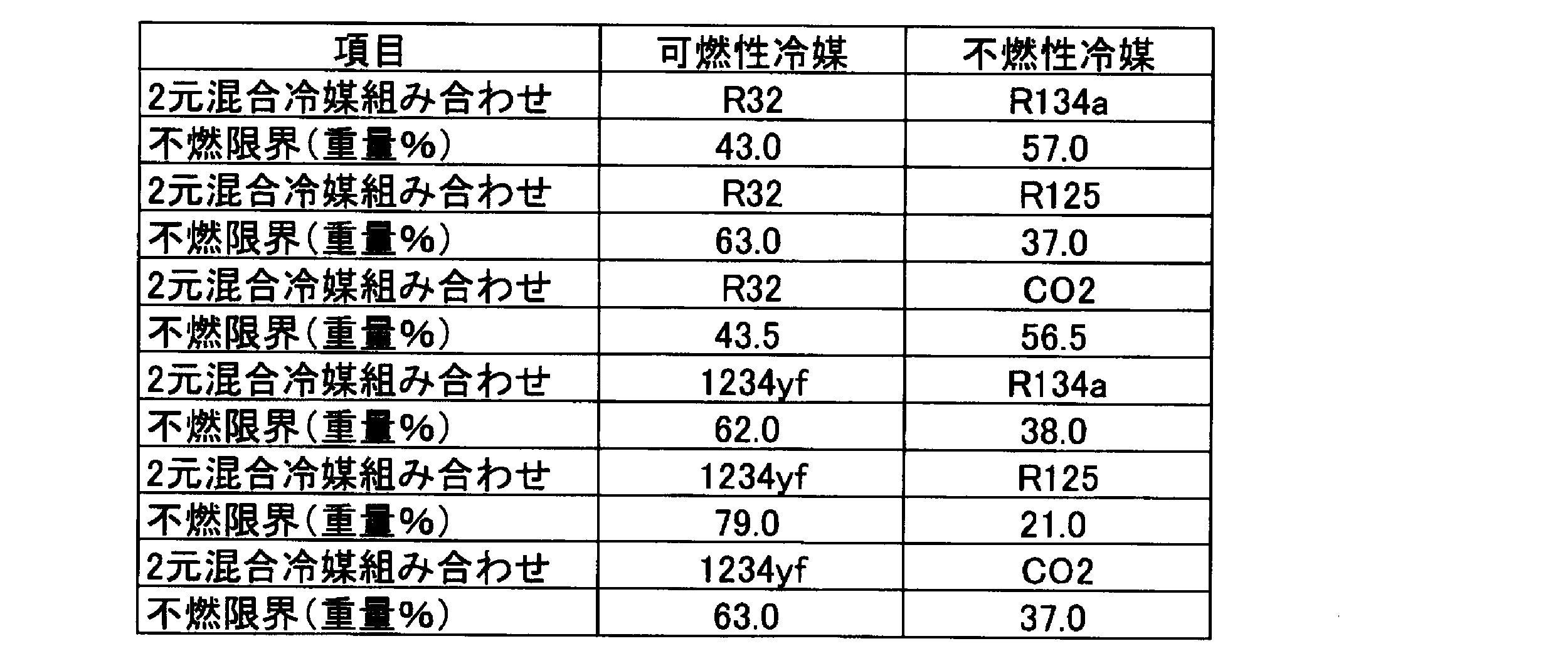
a+b=59質量%とし、以下の手順で混合組成が不燃限界組成になっているかどうかを調べた。
(1) R32換算可燃冷媒濃度=R32濃度+R1234yf濃度×((21/79)×(63/37)+(38/62)×(43/57))/2
(2) R32換算不燃冷媒濃度=R125濃度×(63/37)+R134a濃度×(43/57)+CO2濃度×(43.5/56.5)

a+c=29質量%とし、前記と同様の手順でこの条件での不燃限界組成を求め、その結果を表234に示す。

a+c=44質量%とし、前記と同様の手順でこの条件での不燃限界組成を求め、その結果を表235に示す。

a+c=59質量%とし、前記と同様の手順でこの条件での不燃限界組成を求め、その結果を表236に示す。

表233で示す組成、
可燃限界組成-1-1)(R32/CO2/R125/R134a)=(15.1/43.9/0.0/0.0)、
不燃限界組成-1-2)(R32/CO2/R125/R134a)=(15.0/44.0/0.0/0.0)、
表235で示す組成、
可燃限界組成-2-1)(R32/CO2/R125/R134a)=(18.3/15.0/6.4/19.3)、
不燃限界組成-2-2)(R32/CO2/R125/R134a)=(18.2/15.0/6.5/19.3)、
を[1]で示したASTM E681に従って燃焼試験を行ったところ、組成-1-1)、組成-2-1)は火炎伝播が認められ、組成1-1-2)、組成-2-2)は火炎伝播は認められなかった。従って、2元混合冷媒の不燃限界から求めた混合冷媒の不燃限界は実際の不燃限界を示しているといえる。
Refleakで貯蔵/輸送時の漏洩試験、装置からの漏洩試験、漏洩・再充填試験を行なったところ、貯蔵/輸送時の漏洩条件が一番燃えやすい条件であり、かつ、-40℃での漏洩が一番燃えやすい条件であった。従って、ASHRAE不燃限界は、貯蔵/輸送時で-40℃での漏洩試験を、Refleakでの漏洩シミュレーションを行い以下の手順で求めた。表237は漏洩シミュレーションでの可燃/不燃の限界となる代表値を示す。初期組成が(0.0,39.5,19.5(4.9+14.6))のときに輸送及び貯蔵条件では-40℃、52%放出時に大気圧になり、その時の液側の濃度はx=67.0質量%で(0.0,2.5,30.5(6.1+24.4))であり、前記した不燃判定では大気圧条件で不燃となる限界であった。一方、初期組成が(0.0,39.6,19.4(4.9+14.5))では-40℃、52%放出時に大気圧になり、その時の液側濃度はx=67.1%で(0.0,2.6,30.3(6.1+24.2))であり、前記した不燃判定では可燃であった。従って、初期組成が(0.0,39.5,19.5(4.9+14.6))をWCF組成とした場合に、WCF組成、WCFF組成ともに計算上不燃と判断されるので、(0.0,39.5,19.5(4.9+14.6))がASHRAE不燃限界組成である。

X=41.0質量%、r=0.25の条件では、a+b+c=100-x=59質量%で示される3成分組成図でGWP=750となる点は図2I8に示しているように、点Cr=0.25(31.6,0.0,27.4(6.9+20.5))と点Dr=0.25(0.0,20.6,38.4(9.6+28.8))を結んだ直線Cr=0.25 Dr=0.25にあり、この直線はc1=-0.085a+9.6で示される。GWP=750でASHRAE不燃限界となるPr=0.25(a,-0.085c1+9.6,c)は、初期組成をこの条件で設定し、Refleakで貯蔵/輸送の条件で-40℃シミュレーションすることでASHRAE不燃限界組成を表238のように求めた。
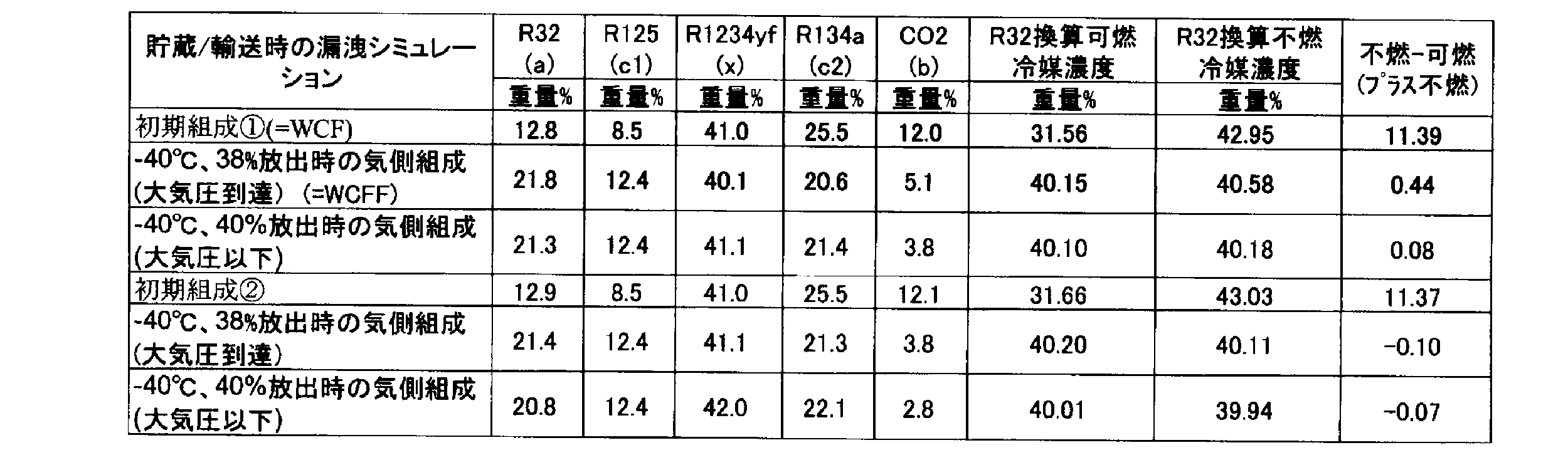
上記と同様に調べた結果を表239に示す。

上記と同様に調べた結果を表240に示す。

下記組成を[1]で示したASTM E681に従って燃焼試験を行ったところ、組成-3-1)、組成-4-1)、及び組成5-1)は火炎伝播が認められず、組成-3-2)、組成-4-2)、及び組成-5-2)は火炎伝播が認められた。従って、表237,238,239の計算で示したASHRAE不燃限界は実際の不燃限界を示しているといえる。
組成3-1)
x=R1234yf=41.0質量%、(R32/CO2/R125/R134a)=(0.0/39.5/4.9/14.6)の-40℃、52%放出時の液側組成、x=67.0%、(R32/CO2/R125/R134a)=(0.0/2.5/6.1/24.4)
組成3-2)
x=R1234yf=41.0質量%、(R32/CO2/R125/R134a)=(0.0/39.6/4.9/14.5)の-40℃、52%放出時の液側組成、x=67.1%、(R32/CO2/R125/R134a)=(0.0/2.6/6.1/24.2)
組成4-1)
x=R1234yf=41.0質量%、(R32/CO2/R125/R134a)=(12.8/12.2/8.5/25.5)の-40℃、38%放出時の気側組成、x=40.1%、(R32/CO2/R125/R134a)=(21.8/5.1/12.4/20.6)
組成4-2)
x=R1234yf=41.0質量%、(R32/CO2/R125/R134a)=(12.9/12.1/8.5/25.5)の-40℃、38%放出時の気側組成、x=41.1%、(R32/CO2/R125/R134a)=(21.4/3.8/12.4/21.3)
組成5-1)
x=R1234yf=41.0質量%、(R32/CO2/R125/R134a)=(5.8/30.0/5.8/17.4)の-40℃、50%放出時の液側組成、x=61.2%、(R32/CO2/R125/R134a)=(4.1/1.1/6.4/27.2)
組成5-2)
x=R1234yf=41.0質量%、(R32/CO2/R125/R134a)=(5.8/30.1/5.8/17.3)の-40℃、50%放出時の液側組成、x=61.4%、(R32/CO2/R125/R134a)=(4.1/1.1/6.4/27.0)
図2I8には表237,238,239,240で示したASHRAE不燃限界点と点Fr=0.25 と点Pr=0.25より結んだ直線Fr=0.25 Pr=0.25を示す。ASHRAE不燃限界点は、図2I8で示すように直線Fr=0.25Pr=0.25より可燃冷媒R32側にあるが、安全率も見込んでここでは点Fr=0.25、点Pr=0.25をを求めることで得られる直線Fr=0.25Pr=0.25をASHRAE不燃限界線とする。
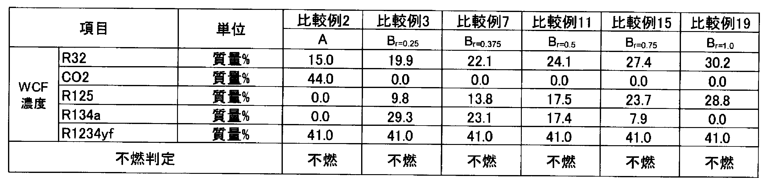

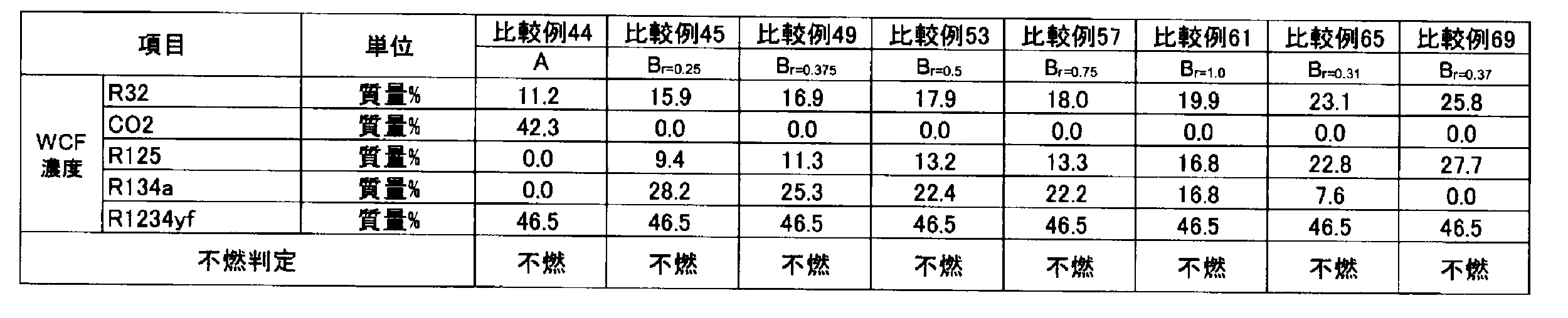


R410A、R32、R125、R1234yf、R134a及びCO2の混合物を含有する組成物のGWPは、IPCC(Intergovernmental Panel on Climate Change)第4次報告書の値に基づいて評価した。また、R410A 並びにR32、R125、R1234yf、R134a及びCO2の混合物を含有する組成物の冷凍能力は、National Institute of Science and Technology(NIST) Reference Fluid Thermodynamic and Transport Properties Database(Refprop 9.0)を使い、下記条件で混合冷媒の冷凍サイクル理論計算を実施することにより求めた。
蒸発温度 -10℃
凝縮温度 45℃
過熱温度 20K
過冷却温度 5K
圧縮機効率 70%
また、これらの結果をもとに算出したGWP、COP及び冷凍能力を表249~280に示す。なお、COP及び冷凍能力については、R410Aに対する割合を示す。
COP =(冷凍能力又は暖房能力)/消費電力量
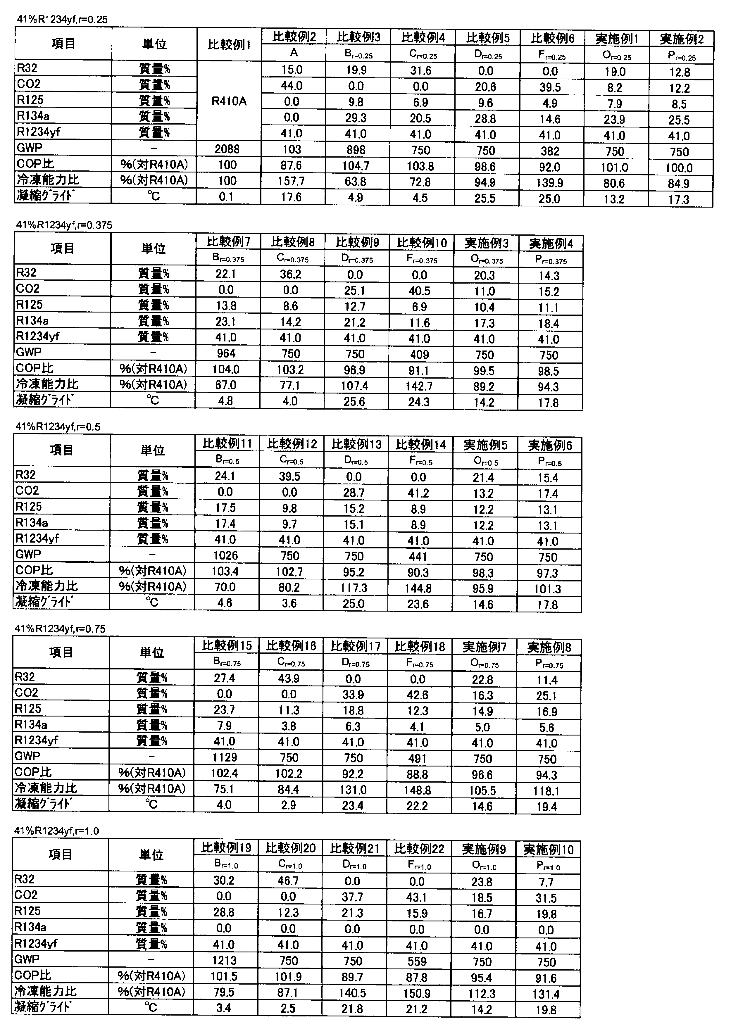


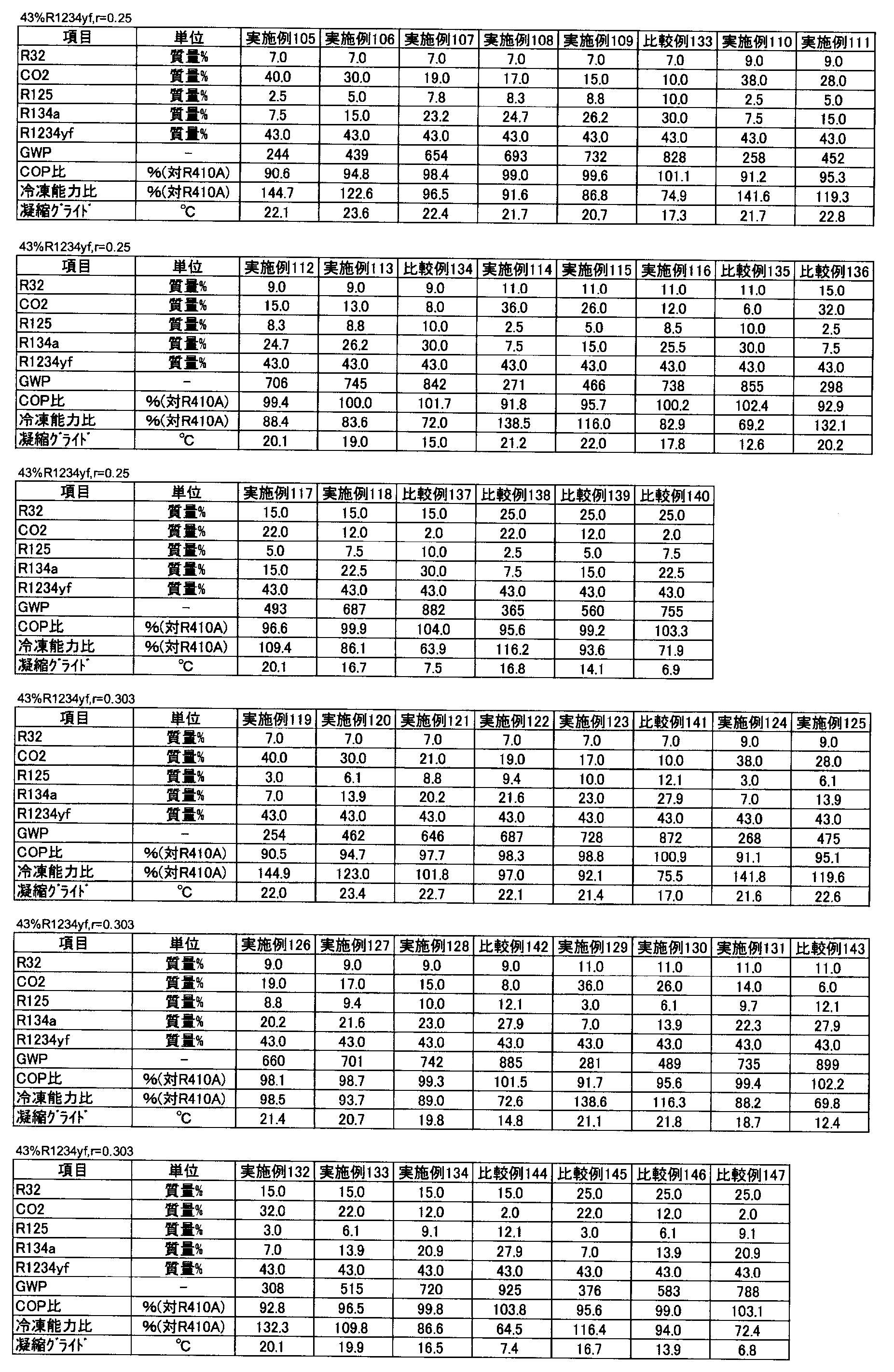

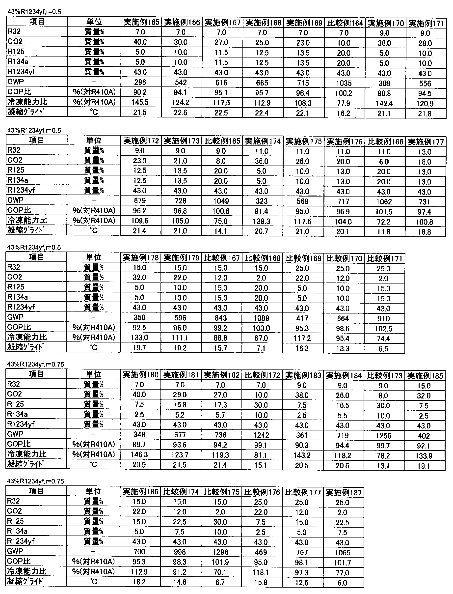
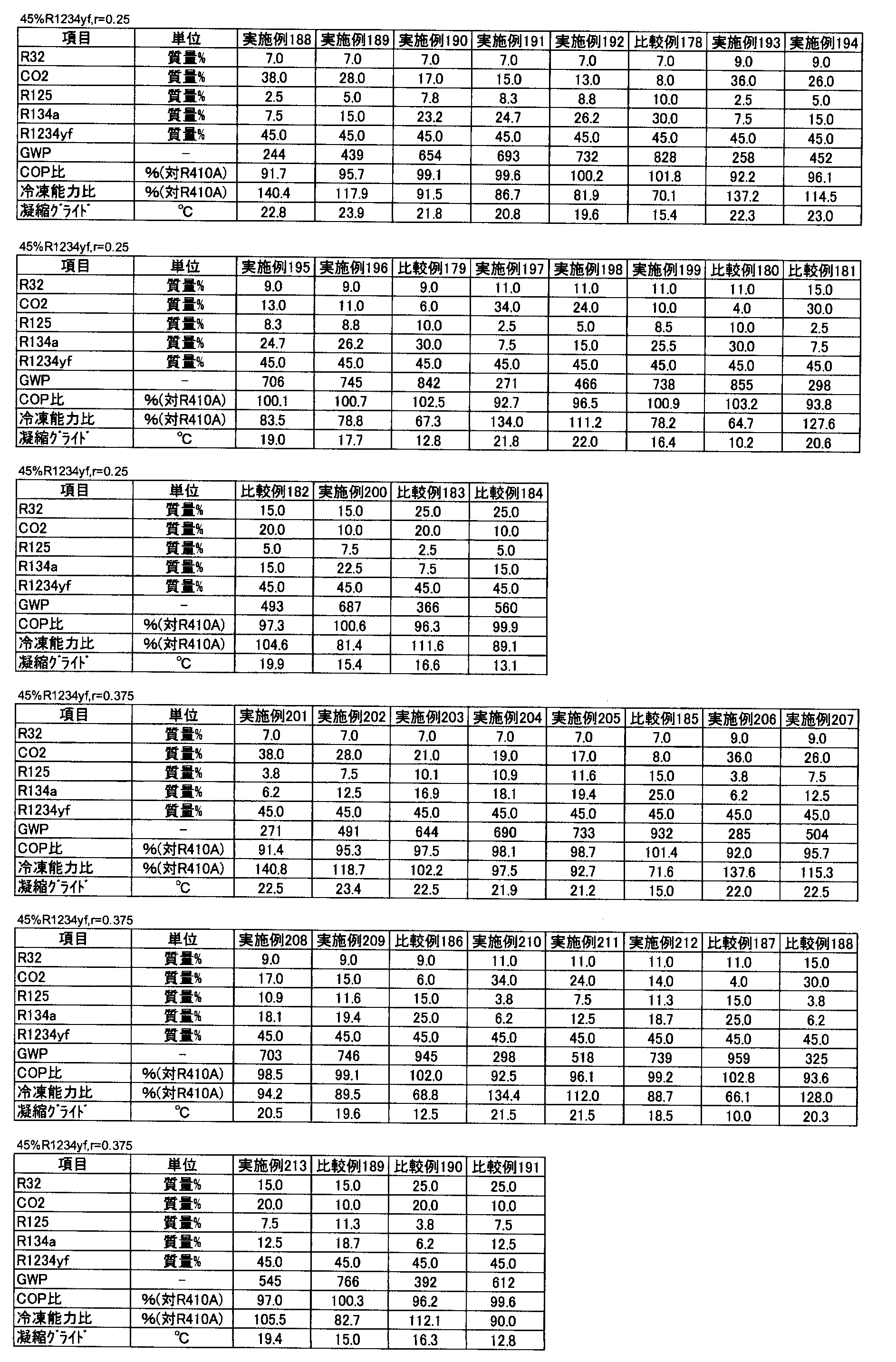

点A
上記のようにして明らかになった、点Aの4種の組成に基づいて、以下のようにして最小二乗法によりR1234yfの割合(x)の関数として点Aの座標の近似式を求めた。すなわち、点Aの座標(a,b,c)=(-0.6902x+43.307, 100-a-x, 0.0)となることが判った。
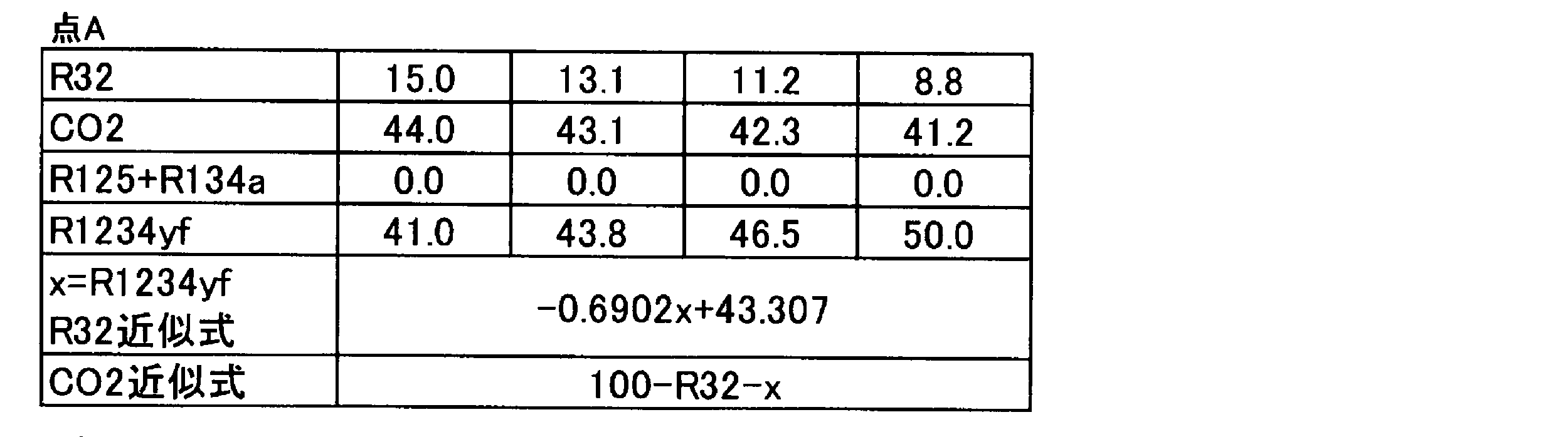
また、上記のようにして明らかになった、点Brの組成に基づいて、以下のようにして最小二乗法と計算によりr、及びR1234yfの割合(x)の関数として点Brの座標の近似式を求めた。
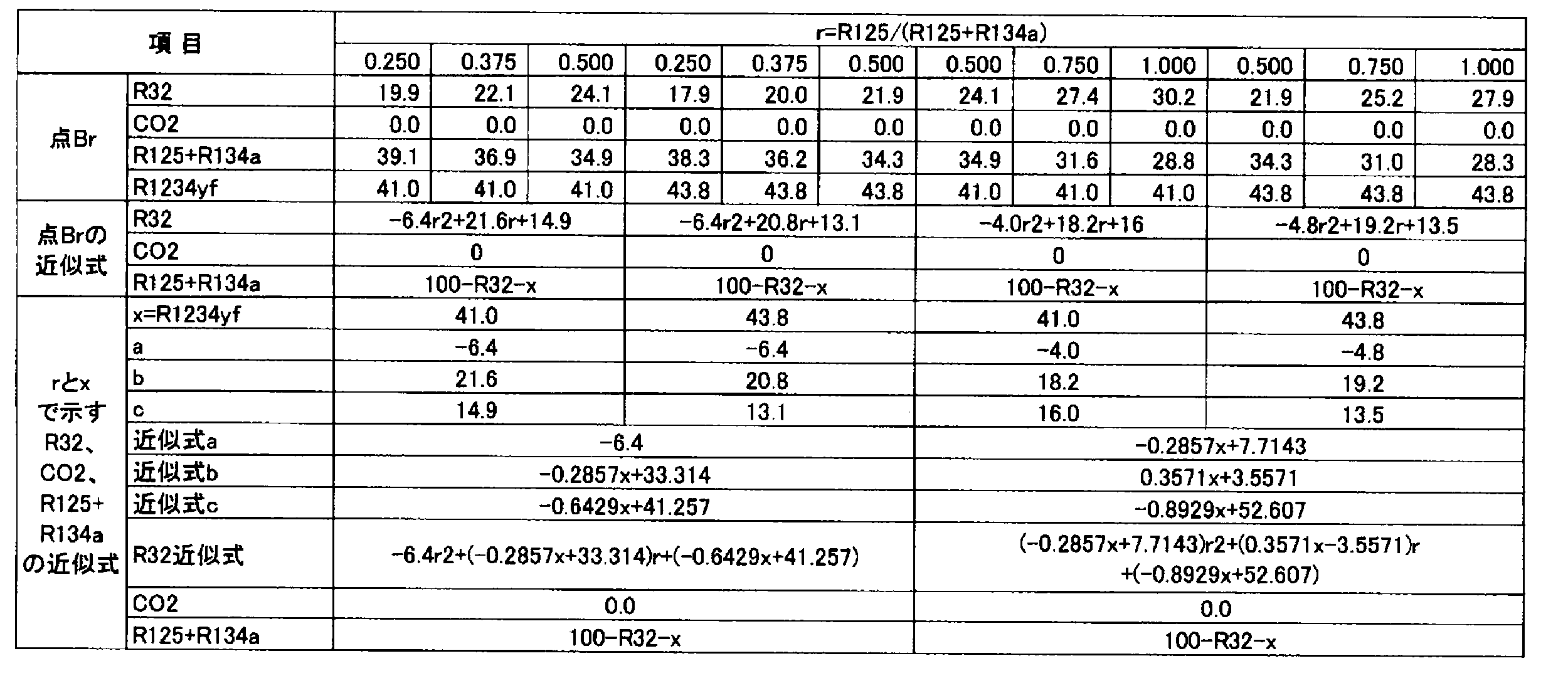

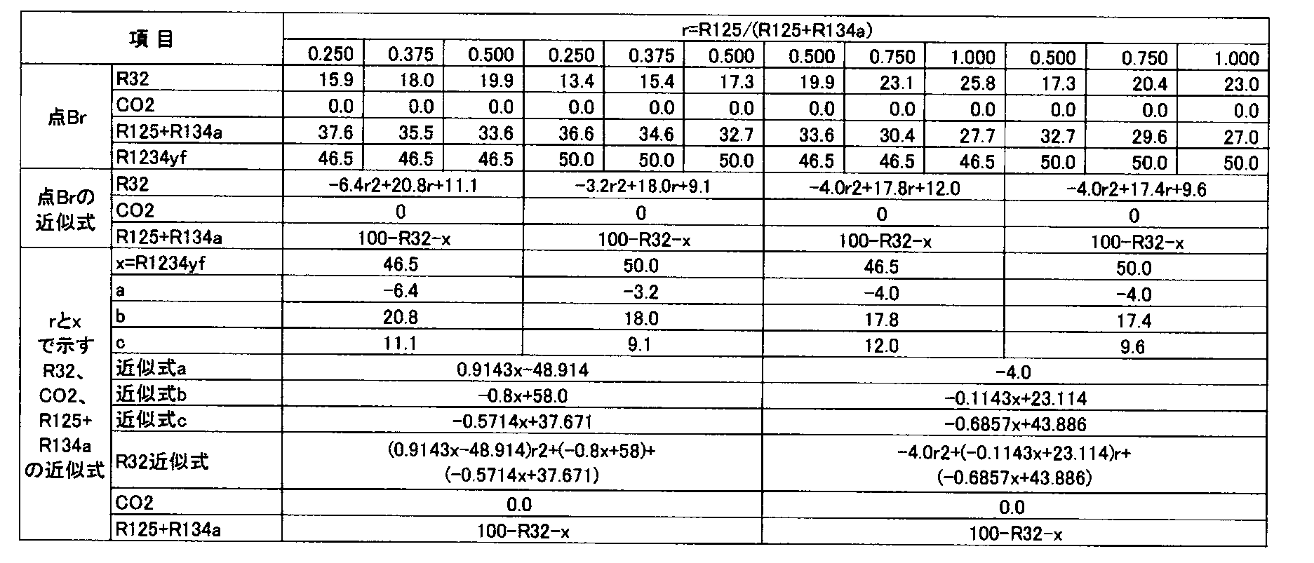
また、上記のようにして明らかになった、点Cr、点Drの組成に基づいて、以下のようにして最小二乗法と計算によりr、及びR1234yfの割合(x)の関数として点Cr、点Dr座標の近似式を求めた。


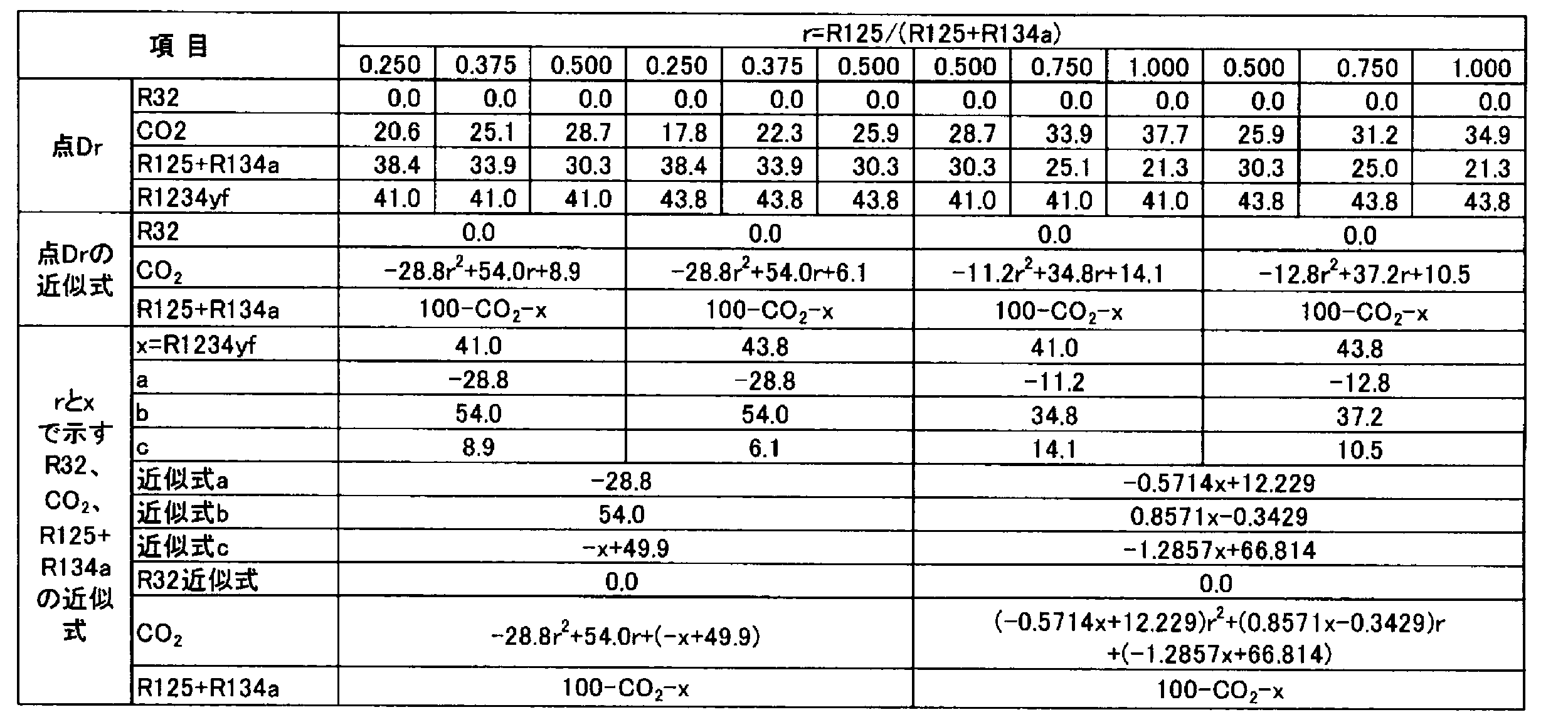


線分ABrと線分CrDrとの交点であるOrの各点は実施例及び比較例で示しているが、Orの組成に基づいて、以下のようにして最小二乗法と計算によりr、及びR1234yfの割合(x)の関数として点Or座標の近似式を求めた。


点Frと点Prの各点は実施例及び比較例で示しているが、各組成に基づいて、以下のようにして最小二乗法と計算によりr、及びR1234yfの割合(x)の関数として点Fr、点Pr座標の近似式を求めた。


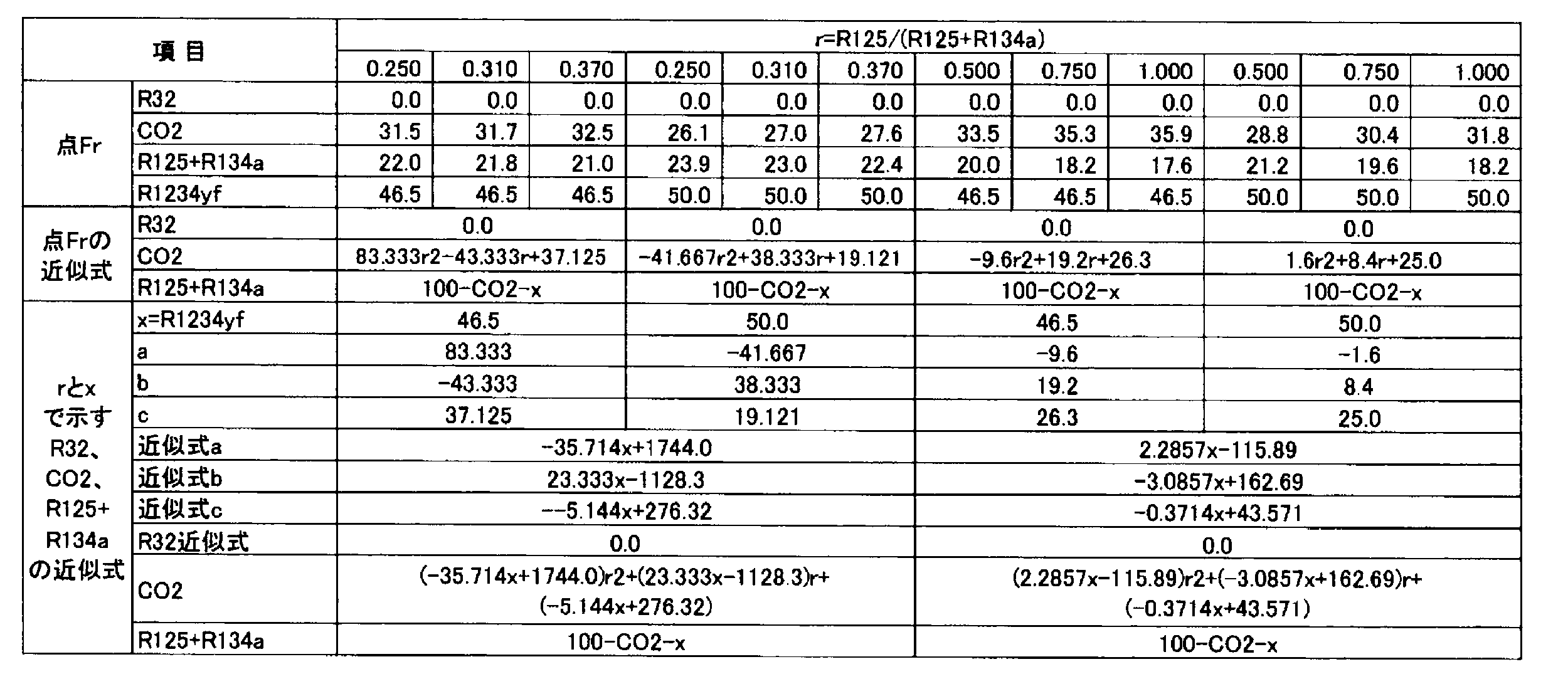

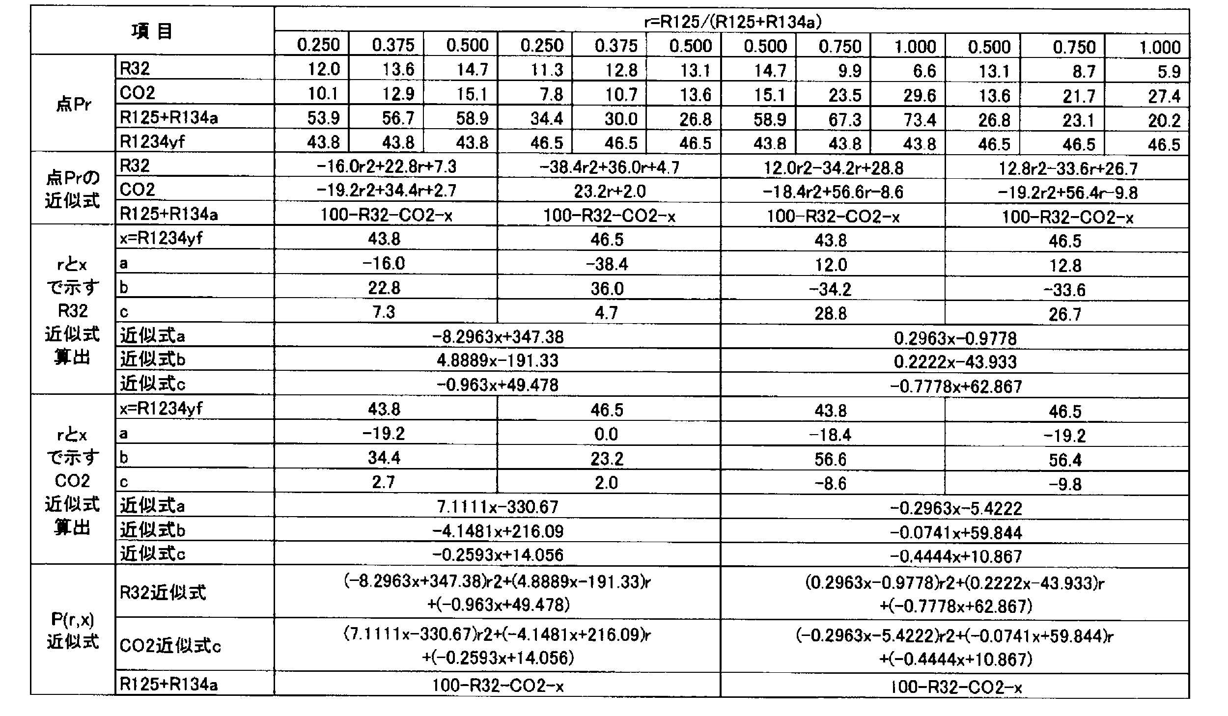

第2グループの技術としての冷凍機油は、冷媒組成物と共存させて冷凍サイクルを行わせることで、冷凍サイクル装置内の潤滑性を高めることが可能であり、効率的なサイクル性能を発揮させることも可能となる。
含酸素系合成油であるエステル系冷凍機油やエーテル系冷凍機油は、主として、炭素原子と酸素原子を有して構成されている。エステル系冷凍機油やエーテル系冷凍機油においては、この炭素原子と酸素原子の比率(炭素/酸素モル比)が小さすぎると吸湿性が高くなり、当該比率が大きすぎると冷媒との相溶性が低下してしまうことから、当該比率はモル比で2以上7.5以下であることが好ましい。
エステル系冷凍機油としては、化学的安定性の観点から、二塩基酸と1価アルコールとの二塩基酸エステル油、ポリオールと脂肪酸とのポリオールエステル油、またはポリオールと多価塩基酸と1価アルコール(又は脂肪酸)とのコンプレックスエステル油、ポリオール炭酸エステル油等が基油成分として挙げられる。
二塩基酸エステル油としては、シュウ酸、マロン酸、コハク酸、グルタル酸、アジピン酸、ピメリン酸、スベリン酸、アゼライン酸、セバシン酸、フタル酸、イソフタル酸、テレフタル酸等の二塩基酸、特に、炭素数5~10の二塩基酸(グルタル酸、アジピン酸、ピメリン酸、スベリン酸、アゼライン酸、セバシン酸等)と、直鎖または分枝アルキル基を有する炭素数1~15の一価アルコール(メタノール、エタノール、プロパノール、ブタノール、ペンタノール、ヘキサノール、ヘプタノール、オクタノール、ノナノール、デカノール、ウンデカノール、ドデカノール、トリデカノール、テトラデカノール、ペンタデカノール等)とのエステルが好ましい。この二塩基酸エステル油としては、具体的には、グルタル酸ジトリデシル、アジピン酸ジ(2-エチルヘキシル)、アジピン酸ジイソデシル、アジピン酸ジトリデシル、セバシン酸ジ(3-エチルヘキシル)等が挙げられる。
ポリオールエステル油とは、多価アルコールと脂肪酸(カルボン酸)とから合成されるエステルであり、炭素/酸素モル比が2以上7.5以下、好ましくは3.2以上5.8以下のものである。
(i)ブタン酸、2-メチルプロパン酸、ペンタン酸、2-メチルブタン酸、3-メチルブタン酸、2,2-ジメチルプロパン酸、2-メチルペンタン酸、3-メチルペンタン酸、4-メチルペンタン酸、2,2-ジメチルブタン酸、2,3-ジメチルブタン酸、3,3-ジメチルブタン酸およびヘキサン酸から選ばれる1~13種と、2-メチルヘキサン酸、3-メチルヘキサン酸、4-メチルヘキサン酸、5-メチルヘキサン酸、2,2-ジメチルペンタン酸、2,3-ジメチルペンタン酸、2,4-ジメチルペンタン酸、3,3-ジメチルペンタン酸、3,4-ジメチルペンタン酸、4,4-ジメチルペンタン酸、2-エチルペンタン酸、3-エチルペンタン酸および2-エチル-3-メチルブタン酸から選ばれる1~13種との組合せ;
(ii)ブタン酸、2-メチルプロパン酸、ペンタン酸、2-メチルブタン酸、3-メチルブタン酸、2,2-ジメチルプロパン酸、2-メチルペンタン酸、3-メチルペンタン酸、4-メチルペンタン酸、2,2-ジメチルブタン酸、2,3-ジメチルブタン酸、3,3-ジメチルブタン酸およびヘキサン酸から選ばれる1~13種と、2-メチルヘプタン酸、3-メチルヘプタン酸、4-メチルヘプタン酸、5-メチルヘプタン酸、6-メチルヘプタン酸、2,2-ジメチルヘキサン酸、3,3-ジメチルヘキサン酸、4,4-ジメチルヘキサン酸、5,5-ジメチルヘキサン酸、2,3-ジメチルヘキサン酸、2,4-ジメチルヘキサン酸、2,5-ジメチルヘキサン酸、3,4-ジメチルヘキサン酸、3,5-ジメチルヘキサン酸、4,5-ジメチルヘキサン酸、2,2,3-トリメチルペンタン酸、2,3,3-トリメチルペンタン酸、2,4,4-トリメチルペンタン酸、3,4,4-トリメチルペンタン酸、2-エチルヘキサン酸、3-エチルヘキサン酸、2-プロピルペンタン酸、2-メチル-2-エチルペンタン酸、2-メチル-3-エチルペンタン酸および3-メチル-3-エチルペンタン酸から選ばれる1~25種との組合せ;
(iii)ブタン酸、2-メチルプロパン酸、ペンタン酸、2-メチルブタン酸、3-メチルブタン酸、2,2-ジメチルプロパン酸、2-メチルペンタン酸、3-メチルペンタン酸、4-メチルペンタン酸、2,2-ジメチルブタン酸、2,3-ジメチルブタン酸、3,3-ジメチルブタン酸およびヘキサン酸から選ばれる1~13種と、2-メチルオクタン酸、3-メチルオクタン酸、4-メチルオクタン酸、5-メチルオクタン酸、6-メチルオクタン酸、7-メチルオクタン酸、8-メチルオクタン酸、2,2-ジメチルヘプタン酸、3,3-ジメチルヘプタン酸、4,4-ジメチルヘプタン酸、5,5-ジメチルヘプタン酸、6,6-ジメチルヘプタン酸、2,3-ジメチルヘプタン酸、2,4-ジメチルヘプタン酸、2,5-ジメチルヘプタン酸、2,6-ジメチルヘプタン酸、3,4-ジメチルヘプタン酸、3,5-ジメチルヘプタン酸、3,6-ジメチルヘプタン酸、4,5-ジメチルヘプタン酸、4,6-ジメチルヘプタン酸、2-エチルヘプタン酸、3-エチルヘプタン酸、4-エチルヘプタン酸、5-エチルヘプタン酸、2-プロピルヘキサン酸、3-プロピルヘキサン酸、2-ブチルペンタン酸、2,2,3-トリメチルヘキサン酸、2,2,3-トリメチルヘキサン酸、2,2,4-トリメチルヘキサン酸、2,2,5-トリメチルヘキサン酸、2,3,4-トリメチルヘキサン酸、2,3,5-トリメチルヘキサン酸、3,3,4-トリメチルヘキサン酸、3,3,5-トリメチルヘキサン酸、3,5,5-トリメチルヘキサン酸、4,4,5-トリメチルヘキサン酸、4,5,5-トリメチルヘキサン酸、2,2,3,3-テトラメチルペンタン酸、2,2,3,4-テトラメチルペンタン酸、2,2,4,4-テトラメチルペンタン酸、2,3,4,4-テトラメチルペンタン酸、3,3,4,4-テトラメチルペンタン酸、2,2-ジエチルペンタン酸、2,3-ジエチルペンタン酸、3,3-ジエチルペンタン酸、2-エチル-2,3,3-トリメチル酪酸、3-エチル-2,2,3-トリメチル酪酸および2,2-ジイソプロピルプロピオン酸から選ばれる1~50種との組合せ。
(i)2-メチルプロパン酸と、2-メチルヘキサン酸、3-メチルヘキサン酸、4-メチルヘキサン酸、5-メチルヘキサン酸、2,2-ジメチルペンタン酸、2,3-ジメチルペンタン酸、2,4-ジメチルペンタン酸、3,3-ジメチルペンタン酸、3,4-ジメチルペンタン酸、4,4-ジメチルペンタン酸、2-エチルペンタン酸、3-エチルペンタン酸および2-エチル-3-メチルブタン酸から選ばれる1~13種との組合せ;
(ii)2-メチルプロパン酸と、2-メチルヘプタン酸、3-メチルヘプタン酸、4-メチルヘプタン酸、5-メチルヘプタン酸、6-メチルヘプタン酸、2,2-ジメチルヘキサン酸、3,3-ジメチルヘキサン酸、4,4-ジメチルヘキサン酸、5,5-ジメチルヘキサン酸、2,3-ジメチルヘキサン酸、2,4-ジメチルヘキサン酸、2,5-ジメチルヘキサン酸、3,4-ジメチルヘキサン酸、3,5-ジメチルヘキサン酸、4,5-ジメチルヘキサン酸、2,2,3-トリメチルペンタン酸、2,3,3-トリメチルペンタン酸、2,4,4-トリメチルペンタン酸、3,4,4-トリメチルペンタン酸、2-エチルヘキサン酸、3-エチルヘキサン酸、2-プロピルペンタン酸、2-メチル-2-エチルペンタン酸、2-メチル-3-エチルペンタン酸および3-メチル-3-エチルペンタン酸から選ばれる1~25種との組合せ;
(iii)2-メチルプロパン酸と、2-メチルオクタン酸、3-メチルオクタン酸、4-メチルオクタン酸、5-メチルオクタン酸、6-メチルオクタン酸、7-メチルオクタン酸、8-メチルオクタン酸、2,2-ジメチルヘプタン酸、3,3-ジメチルヘプタン酸、4,4-ジメチルヘプタン酸、5,5-ジメチルヘプタン酸、6,6-ジメチルヘプタン酸、2,3-ジメチルヘプタン酸、2,4-ジメチルヘプタン酸、2,5-ジメチルヘプタン酸、2,6-ジメチルヘプタン酸、3,4-ジメチルヘプタン酸、3,5-ジメチルヘプタン酸、3,6-ジメチルヘプタン酸、4,5-ジメチルヘプタン酸、4,6-ジメチルヘプタン酸、2-エチルヘプタン酸、3-エチルヘプタン酸、4-エチルヘプタン酸、5-エチルヘプタン酸、2-プロピルヘキサン酸、3-プロピルヘキサン酸、2-ブチルペンタン酸、2,2,3-トリメチルヘキサン酸、2,2,3-トリメチルヘキサン酸、2,2,4-トリメチルヘキサン酸、2,2,5-トリメチルヘキサン酸、2,3,4-トリメチルヘキサン酸、2,3,5-トリメチルヘキサン酸、3,3,4-トリメチルヘキサン酸、3,3,5-トリメチルヘキサン酸、3,5,5-トリメチルヘキサン酸、4,4,5-トリメチルヘキサン酸、4,5,5-トリメチルヘキサン酸、2,2,3,3-テトラメチルペンタン酸、2,2,3,4-テトラメチルペンタン酸、2,2,4,4-テトラメチルペンタン酸、2,3,4,4-テトラメチルペンタン酸、3,3,4,4-テトラメチルペンタン酸、2,2-ジエチルペンタン酸、2,3-ジエチルペンタン酸、3,3-ジエチルペンタン酸、2-エチル-2,3,3-トリメチル酪酸、3-エチル-2,2,3-トリメチル酪酸および2,2-ジイソプロピルプロピオン酸から選ばれる1~50種との組合せ。
コンプレックスエステル油とは、脂肪酸および二塩基酸と、一価アルコールおよびポリオールとのエステルである。脂肪酸、二塩基酸、一価アルコール、ポリオールとしては、上述と同様のものを用いることができる。
ポリオール炭酸エステル油とは、炭酸とポリオールとのエステルである。
エーテル系冷凍機油としては、ポリビニルエーテル油、ポリオキシアルキレン油等が挙げられる。
ポリビニルエーテル油としては、ビニルエーテルモノマーの重合体、ビニルエーテルモノマーとオレフィン性二重結合を有する炭化水素モノマーとの共重合体、オレフィン性二重結合とポリオキシアルキレン鎖を有するモノマーとビニルエーテルモノマーとの共重合体等が挙げられる。
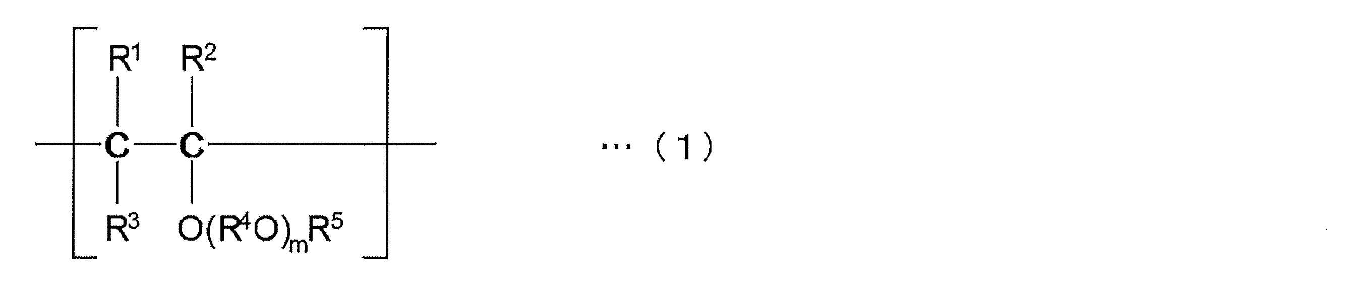


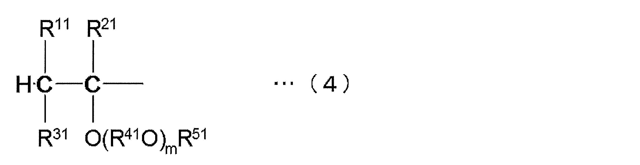


ポリオキシアルキレン油としては、炭素数2~4のアルキレンオキシド(エチレンオキシド、プロピレンオキシド等)を、水や水酸基含有化合物を開始剤として重合させる方法等により得られたポリオキシアルキレン化合物が挙げられる。また、ポリオキシアルキレン化合物の水酸基をエーテル化またはエステル化したものであってもよい。ポリオキシアルキレン油中のオキシアルキレン単位は、1分子中において同一であってもよく、2種以上のオキシアルキレン単位が含まれていてもよい。1分子中に少なくともオキシプロピレン単位が含まれることが好ましい。
R101-[(OR102)k-OR103]l …(9)
(式中、R101は水素原子、炭素数1~10のアルキル基、炭素数2~10のアシル基又は結合部2~6個を有する炭素数1~10の脂肪族炭化水素基、R102は炭素数2~4のアルキレン基、R103は水素原子、炭素数1~10のアルキル基又は炭素数2~10のアシル基、lは1~6の整数、kはk×lの平均値が6~80となる数を示す。)で表される化合物が挙げられる。
(式中、hは6~80の数を表す。)
CH3O-(C2H4O)i-(C3H6O)j-CH3 …(11)
(式中、iおよびjはそれぞれ1以上であり且つiとjとの合計が6~80となる数を表す。)
C4H9O-(C3H6O)h-H …(12)
(式中、hは6~80の数を示す。)
CH3O-(C3H6O)h-H …(13)
(式中、hは6~80の数を表す。)
CH3O-(C2H4O)i-(C3H6O)j-H …(14)
(式中、iおよびjはそれぞれ1以上であり且つiとjとの合計が6~80となる数を表す。)
C4H9O-(C2H4O)i-(C3H6O)j-H …(15)
(式中、iおよびjはそれぞれ1以上であり且つiとjとの合計が6~80となる数を表す。)
CH3COO-(C3H6O)h-COCH3 …(16)
(式中、hは6~80の数を表す。)
このポリオキシアルキレン油は、1種を単独で用いてもよく、2種以上を組み合わせて用いてもよい。
炭化水素系冷凍機油としては、例えば、アルキルベンゼンを用いることができる。
冷凍機油には、1種または2種以上の添加剤が含まれていてもよい。
リン酸エステル類としては、リン酸エステル、亜リン酸エステル、酸性リン酸エステル、及び酸性亜リン酸エステル等を用いることができ、リン酸エステル、亜リン酸エステル、酸性リン酸エステル、及び酸性亜リン酸エステルのアミン塩を含むものを用いることもできる。
第1グループの技術および第3グループの技術としての冷凍サイクル装置は、空気調和装置である。
以下、冷媒回路の概略構成図である図3A、概略制御ブロック構成図である図3Bを参照しつつ、第1実施形態に係る冷凍サイクル装置としての空気調和装置1について説明する。
室外ユニット20は、液側冷媒連絡配管6およびガス側冷媒連絡配管5を介して室内ユニット30と接続されており、冷媒回路10の一部を構成している。室外ユニット20は、主として、圧縮機21と、四路切換弁22と、室外熱交換器23と、室外膨張弁24と、室外ファン25と、液側閉鎖弁29と、ガス側閉鎖弁28と、を有している。
室内ユニット30は、対象空間である室内の壁面や天井等に設置されている。室内ユニット30は、液側冷媒連絡配管6およびガス側冷媒連絡配管5を介して室外ユニット20と接続されており、冷媒回路10の一部を構成している。
空気調和装置1では、室外ユニット制御部27と室内ユニット制御部34が通信線を介して接続されることで、空気調和装置1の動作を制御するコントローラ7が構成されている。
以下、運転モードについて説明する。
空気調和装置1では、冷房運転モードでは、四路切換弁22の接続状態を圧縮機21の吐出側と室外熱交換器23とを接続しつつ圧縮機21の吸入側とガス側閉鎖弁28とを接続する冷房運転接続状態とし、冷媒回路10に充填されている冷媒を、主として、圧縮機21、室外熱交換器23、室外膨張弁24、室内熱交換器31の順に循環させる。
空気調和装置1では、暖房運転モードでは、四路切換弁22の接続状態を圧縮機21の吐出側とガス側閉鎖弁28とを接続しつつ圧縮機21の吸入側と室外熱交換器23とを接続する暖房運転接続状態とし、冷媒回路10に充填されている冷媒を、主として、圧縮機21、室内熱交換器31、室外膨張弁24、室外熱交換器23の順に循環させる。
空気調和装置1では、冷媒X、冷媒Y、冷媒A、冷媒B、冷媒C、冷媒D、あるいは、冷媒Eを用いた冷凍サイクルを行うことができるため、GWPの小さい冷媒を用いて冷凍サイクルを行うことが可能になっている。
以下、冷媒回路の概略構成図である図3C、概略制御ブロック構成図である図3Dを参照しつつ、第2実施形態に係る冷凍サイクル装置としての空気調和装置1aについて説明する。なお、以下では、第1実施形態の空気調和装置1との違いを主に説明する。
空気調和装置1aは、上記第1実施形態の空気調和装置1とは、室外ユニット20が低圧レシーバ41を備えている点で異なっている。
空気調和装置1aでは、冷房運転モードでは、圧縮機21は、例えば、冷媒回路10における冷媒の蒸発温度が、設定温度と室内温度(室内空気温度センサ72の検出温度)との差分に応じて定まる目標蒸発温度になるように、運転周波数が容量制御される。なお、蒸発温度は、特に限定されないが、例えば、吸入圧力センサ63の検出圧力に相当する冷媒の飽和温度として把握してもよい。
空気調和装置1aでは、暖房運転モードでは、圧縮機21は、例えば、冷媒回路10における冷媒の凝縮温度が、設定温度と室内温度(室内空気温度センサ72の検出温度)との差分に応じて定まる目標凝縮温度になるように、運転周波数が容量制御される。なお、凝縮温度は、特に限定されないが、例えば、吐出圧力センサ61の検出圧力に相当する冷媒の飽和温度として把握してもよい。
空気調和装置1aでは、冷媒X、冷媒Y、冷媒A、冷媒B、冷媒C、冷媒D、あるいは、冷媒Eを用いた冷凍サイクルを行うことができるため、GWPの小さい冷媒を用いて冷凍サイクルを行うことが可能になっている。
以下、冷媒回路の概略構成図である図3E、概略制御ブロック構成図である図3Fを参照しつつ、第3実施形態に係る冷凍サイクル装置としての空気調和装置1bについて説明する。なお、以下では、第2実施形態の空気調和装置1aとの違いを主に説明する。
空気調和装置1bは、上記第2実施形態の空気調和装置1aとは、複数の室内ユニットが並列に設けられている点、および、各室内ユニットにおいて室内熱交換器の液冷媒側に室内膨張弁が設けられている点で異なっている。
空気調和装置1bでは、冷房運転モードでは、圧縮機21は、例えば、冷媒回路10における冷媒の蒸発温度が目標蒸発温度になるように、運転周波数が容量制御される。ここで、目標蒸発温度は、各室内ユニット30、35において設定温度と室内温度との差分が最も大きいもの(負荷が最も大きな室内ユニット)に応じて定めることが好ましい。なお、蒸発温度は、特に限定されないが、例えば、吸入圧力センサ63の検出圧力に相当する冷媒の飽和温度として把握することができる。
空気調和装置1bでは、暖房運転モードでは、圧縮機21は、例えば、冷媒回路10における冷媒の凝縮温度が、目標凝縮温度になるように、運転周波数が容量制御される。ここで、目標凝縮温度は、各室内ユニット30、35において設定温度と室内温度との差分が最も大きいもの(負荷が最も大きな室内ユニット)に応じて定めることが好ましい。なお、凝縮温度は、特に限定されないが、例えば、吐出圧力センサ61の検出圧力に相当する冷媒の飽和温度として把握してもよい。
空気調和装置1bでは、冷媒X、冷媒Y、冷媒A、冷媒B、冷媒C、冷媒D、あるいは、冷媒Eを用いた冷凍サイクルを行うことができるため、GWPの小さい冷媒を用いて冷凍サイクルを行うことが可能になっている。
以下、冷媒回路の概略構成図である図3G、概略制御ブロック構成図である図3Hを参照しつつ、第4実施形態に係る冷凍サイクル装置としての空気調和装置1cについて説明する。なお、以下では、第2実施形態の空気調和装置1aとの違いを主に説明する。
空気調和装置1cは、上記第2実施形態の空気調和装置1aとは、室外ユニット20が低圧レシーバ41を備えていない点、高圧レシーバ42を備えている点、室外ブリッジ回路26を備えている点で異なっている。
空気調和装置1cでは、冷房運転モードでは、圧縮機21は、例えば、冷媒回路10における冷媒の蒸発温度が、設定温度と室内温度(室内空気温度センサ72の検出温度)との差分に応じて定まる目標蒸発温度になるように、運転周波数が容量制御される。なお、蒸発温度は、特に限定されないが、例えば、室内液側熱交温度センサ71の検出温度として把握してもよいし、吸入圧力センサ63の検出圧力に相当する冷媒の飽和温度として把握してもよい。
空気調和装置1cでは、暖房運転モードでは、圧縮機21は、例えば、冷媒回路10における冷媒の凝縮温度が、設定温度と室内温度(室内空気温度センサ72の検出温度)との差分に応じて定まる目標凝縮温度になるように、運転周波数が容量制御される。なお、凝縮温度は、特に限定されないが、例えば、吐出圧力センサ61の検出圧力に相当する冷媒の飽和温度として把握してもよい。
空気調和装置1cでは、冷媒X、冷媒Y、冷媒A、冷媒B、冷媒C、冷媒D、あるいは、冷媒Eを用いた冷凍サイクルを行うことができるため、GWPの小さい冷媒を用いて冷凍サイクルを行うことが可能になっている。
以下、冷媒回路の概略構成図である図3I、概略制御ブロック構成図である図3Jを参照しつつ、第5実施形態に係る冷凍サイクル装置としての空気調和装置1dについて説明する。なお、以下では、第4実施形態の空気調和装置1cとの違いを主に説明する。
空気調和装置1dは、上記第4実施形態の空気調和装置1cとは、複数の室内ユニットが並列に設けられている点、および、各室内ユニットにおいて室内熱交換器の液冷媒側に室内膨張弁が設けられている点で異なっている。
空気調和装置1cでは、冷房運転モードでは、圧縮機21は、例えば、冷媒回路10における冷媒の蒸発温度が目標蒸発温度になるように、運転周波数が容量制御される。ここで、目標蒸発温度は、各室内ユニット30、35において設定温度と室内温度との差分が最も大きいもの(負荷が最も大きな室内ユニット)に応じて定めることが好ましい。
空気調和装置1cでは、暖房運転モードでは、圧縮機21は、例えば、冷媒回路10における冷媒の凝縮温度が、目標凝縮温度になるように、運転周波数が容量制御される。ここで、目標凝縮温度は、各室内ユニット30、35において設定温度と室内温度との差分が最も大きいもの(負荷が最も大きな室内ユニット)に応じて定めることが好ましい。なお、凝縮温度は、特に限定されないが、例えば、吐出圧力センサ61の検出圧力に相当する冷媒の飽和温度として把握してもよい。
空気調和装置1dでは、冷媒X、冷媒Y、冷媒A、冷媒B、冷媒C、冷媒D、あるいは、冷媒Eを用いた冷凍サイクルを行うことができるため、GWPの小さい冷媒を用いて冷凍サイクルを行うことが可能になっている。
以下、冷媒回路の概略構成図である図3K、概略制御ブロック構成図である図3Lを参照しつつ、第6実施形態に係る冷凍サイクル装置としての空気調和装置1eについて説明する。なお、以下では、第2実施形態の空気調和装置1aとの違いを主に説明する。
空気調和装置1eは、上記第2実施形態の空気調和装置1aとは、室外ユニット20が低圧レシーバ41を有していない点、中間圧レシーバ43を有している点、室外膨張弁24を有していない点、第1室外膨張弁44および第2室外膨張弁45を有している点で異なっている。
空気調和装置1eでは、冷房運転モードでは、圧縮機21は、例えば、冷媒回路10における冷媒の蒸発温度が、設定温度と室内温度(室内空気温度センサ72の検出温度)との差分に応じて定まる目標蒸発温度になるように、運転周波数が容量制御される。
空気調和装置1eでは、暖房運転モードでは、圧縮機21は、例えば、冷媒回路10における冷媒の凝縮温度が、設定温度と室内温度(室内空気温度センサ72の検出温度)との差分に応じて定まる目標凝縮温度になるように、運転周波数が容量制御される。
空気調和装置1eでは、冷媒X、冷媒Y、冷媒A、冷媒B、冷媒C、冷媒D、あるいは、冷媒Eを用いた冷凍サイクルを行うことができるため、GWPの小さい冷媒を用いて冷凍サイクルを行うことが可能になっている。
以下、冷媒回路の概略構成図である図3M、概略制御ブロック構成図である図3Nを参照しつつ、第7実施形態に係る冷凍サイクル装置としての空気調和装置1fについて説明する。なお、以下では、第6実施形態の空気調和装置1eとの違いを主に説明する。
空気調和装置1fは、上記第6実施形態の空気調和装置1eとは、室外ユニット20が互いに並列に配置された第1室外熱交換器23aおよび第2室外熱交換器23bを有している点、第1室外熱交換器23aの液冷媒側に第1分岐室外膨張弁24aを有し、第2室外熱交換器23bの液冷媒側に第2分岐室外膨張弁24bを有している点で異なっている。なお、第1分岐室外膨張弁24aおよび第2分岐室外膨張弁24bは、弁開度を調節可能な電動膨張弁であることが好ましい。
空気調和装置1fでは、冷房運転モードでは、圧縮機21は、例えば、冷媒回路10における冷媒の蒸発温度が目標蒸発温度になるように、運転周波数が容量制御される。ここで、目標蒸発温度は、各室内ユニット30、35において設定温度と室内温度との差分が最も大きいもの(負荷が最も大きな室内ユニット)に応じて定めることが好ましい。
空気調和装置1fでは、暖房運転モードでは、圧縮機21は、例えば、冷媒回路10における冷媒の凝縮温度が、目標凝縮温度になるように、運転周波数が容量制御される。ここで、目標凝縮温度は、各室内ユニット30、35において設定温度と室内温度との差分が最も大きいもの(負荷が最も大きな室内ユニット)に応じて定めることが好ましい。
空気調和装置1fでは、冷媒X、冷媒Y、冷媒A、冷媒B、冷媒C、冷媒D、あるいは、冷媒Eを用いた冷凍サイクルを行うことができるため、GWPの小さい冷媒を用いて冷凍サイクルを行うことが可能になっている。
以下、冷媒回路の概略構成図である図3O、概略制御ブロック構成図である図3Pを参照しつつ、第8実施形態に係る冷凍サイクル装置としての空気調和装置1gについて説明する。なお、以下では、第3実施形態の空気調和装置1bとの違いを主に説明する。
空気調和装置1gは、上記第3実施形態の空気調和装置1bとは、バイパス膨張弁49を有するバイパス配管40が設けられていない点、過冷却熱交換器47が設けられている点、過冷却配管46が設けられている点、第1室外膨張弁44および第2室外膨張弁45が設けられている点、過冷却温度センサ67が設けられている点において異なっている。
空気調和装置1gでは、冷房運転モードでは、圧縮機21は、例えば、冷媒回路10における冷媒の蒸発温度が目標蒸発温度になるように、運転周波数が容量制御される。ここで、目標蒸発温度は、各室内ユニット30、35において設定温度と室内温度との差分が最も大きいもの(負荷が最も大きな室内ユニット)に応じて定めることが好ましい。
空気調和装置1gでは、暖房運転モードでは、圧縮機21は、例えば、冷媒回路10における冷媒の凝縮温度が、目標凝縮温度になるように、運転周波数が容量制御される。ここで、目標凝縮温度は、各室内ユニット30、35において設定温度と室内温度との差分が最も大きいもの(負荷が最も大きな室内ユニット)に応じて定めることが好ましい。
空気調和装置1gでは、冷媒X、冷媒Y、冷媒A、冷媒B、冷媒C、冷媒D、あるいは、冷媒Eを用いた冷凍サイクルを行うことができるため、GWPの小さい冷媒を用いて冷凍サイクルを行うことが可能になっている。
以下、冷媒回路の概略構成図である図3Q、概略制御ブロック構成図である図3Rを参照しつつ、第9実施形態に係る冷凍サイクル装置としての空気調和装置1hについて説明する。なお、以下では、第6実施形態の空気調和装置1eとの違いを主に説明する。
空気調和装置1hは、上記第6実施形態の空気調和装置1eとは、吸入冷媒加熱部50を有している点で異なっている。
空気調和装置1hでは、冷房運転モードでは、圧縮機21は、例えば、冷媒回路10における冷媒の蒸発温度が、設定温度と室内温度(室内空気温度センサ72の検出温度)との差分に応じて定まる目標蒸発温度になるように、運転周波数が容量制御される。
空気調和装置1hでは、暖房運転モードでは、圧縮機21は、例えば、冷媒回路10における冷媒の凝縮温度が、設定温度と室内温度(室内空気温度センサ72の検出温度)との差分に応じて定まる目標凝縮温度になるように、運転周波数が容量制御される。
空気調和装置1hでは、冷媒X、冷媒Y、冷媒A、冷媒B、冷媒C、冷媒D、あるいは、冷媒Eを用いた冷凍サイクルを行うことができるため、GWPの小さい冷媒を用いて冷凍サイクルを行うことが可能になっている。
以下、冷媒回路の概略構成図である図3S、概略制御ブロック構成図である図3Tを参照しつつ、第10実施形態に係る冷凍サイクル装置としての空気調和装置1iについて説明する。なお、以下では、第9実施形態の空気調和装置1hとの違いを主に説明する。
空気調和装置1iは、上記第9実施形態の空気調和装置1hとは、第1室外膨張弁44と第2室外膨張弁45が設けられておらず、室外膨張弁24が設けられている点、複数の室内ユニット(第1室内ユニット30と第2室内ユニット35)が並列に設けられている点、および、各室内ユニットにおいて室内熱交換器の液冷媒側に室内膨張弁が設けられている点で異なっている。
空気調和装置1iでは、冷房運転モードでは、圧縮機21は、例えば、冷媒回路10における冷媒の蒸発温度が目標蒸発温度になるように、運転周波数が容量制御される。ここで、目標蒸発温度は、各室内ユニット30、35において設定温度と室内温度との差分が最も大きいもの(負荷が最も大きな室内ユニット)に応じて定めることが好ましい。
空気調和装置1iでは、暖房運転モードでは、圧縮機21は、例えば、冷媒回路10における冷媒の凝縮温度が、目標凝縮温度になるように、運転周波数が容量制御される。ここで、目標凝縮温度は、各室内ユニット30、35において設定温度と室内温度との差分が最も大きいもの(負荷が最も大きな室内ユニット)に応じて定めることが好ましい。
空気調和装置1iでは、冷媒X、冷媒Y、冷媒A、冷媒B、冷媒C、冷媒D、あるいは、冷媒Eを用いた冷凍サイクルを行うことができるため、GWPの小さい冷媒を用いて冷凍サイクルを行うことが可能になっている。
以下、冷媒回路の概略構成図である図3U、概略制御ブロック構成図である図3Vを参照しつつ、第11実施形態に係る冷凍サイクル装置としての空気調和装置1jについて説明する。なお、以下では、第9実施形態の空気調和装置1hとの違いを主に説明する。
空気調和装置1jは、上記第9実施形態の空気調和装置1hとは、吸入冷媒加熱部50が設けられておらず、内部熱交換器51が設けられている点で異なっている。
空気調和装置1jでは、冷房運転モードでは、圧縮機21は、例えば、冷媒回路10における冷媒の蒸発温度が、設定温度と室内温度(室内空気温度センサ72の検出温度)との差分に応じて定まる目標蒸発温度になるように、運転周波数が容量制御される。
空気調和装置1jでは、暖房運転モードでは、圧縮機21は、例えば、冷媒回路10における冷媒の凝縮温度が、設定温度と室内温度(室内空気温度センサ72の検出温度)との差分に応じて定まる目標凝縮温度になるように、運転周波数が容量制御される。
空気調和装置1jでは、冷媒X、冷媒Y、冷媒A、冷媒B、冷媒C、冷媒D、あるいは、冷媒Eを用いた冷凍サイクルを行うことができるため、GWPの小さい冷媒を用いて冷凍サイクルを行うことが可能になっている。
以下、冷媒回路の概略構成図である図3W、概略制御ブロック構成図である図3Xを参照しつつ、第12実施形態に係る冷凍サイクル装置としての空気調和装置1kについて説明する。なお、以下では、第10実施形態の空気調和装置1jとの違いを主に説明する。
空気調和装置1kは、上記第10実施形態の空気調和装置1jとは、第1室外膨張弁44と第2室外膨張弁45が設けられておらず、室外膨張弁24が設けられている点、複数の室内ユニット(第1室内ユニット30と第2室内ユニット35)が並列に設けられている点、および、各室内ユニットにおいて室内熱交換器の液冷媒側に室内膨張弁が設けられている点で異なっている。
空気調和装置1kでは、冷房運転モードでは、圧縮機21は、例えば、冷媒回路10における冷媒の蒸発温度が目標蒸発温度になるように、運転周波数が容量制御される。ここで、目標蒸発温度は、各室内ユニット30、35において設定温度と室内温度との差分が最も大きいもの(負荷が最も大きな室内ユニット)に応じて定めることが好ましい。
空気調和装置1kでは、暖房運転モードでは、圧縮機21は、例えば、冷媒回路10における冷媒の凝縮温度が、目標凝縮温度になるように、運転周波数が容量制御される。ここで、目標凝縮温度は、各室内ユニット30、35において設定温度と室内温度との差分が最も大きいもの(負荷が最も大きな室内ユニット)に応じて定めることが好ましい。
空気調和装置1kでは、冷媒X、冷媒Y、冷媒A、冷媒B、冷媒C、冷媒D、あるいは、冷媒Eを用いた冷凍サイクルを行うことができるため、GWPの小さい冷媒を用いて冷凍サイクルを行うことが可能になっている。
(4-1)第1実施形態
以下、冷媒回路の概略構成図である図4A、概略制御ブロック構成図である図4Bを参照しつつ、第1実施形態に係る熱交換ユニットとしての室内ユニットおよび熱交換ユニットとしての室外ユニットとを備えた冷凍サイクル装置である空気調和装置1について説明する。
室外ユニット20は、図4Cに示すように、外観が略直方体箱状の室外筐体50により構成されている。この室外ユニット20は、図4Dに示すように、仕切板50aによって内部空間が左右に分割されることで、送風機室および機械室が形成されている。
室内ユニット30は、対象空間である室内の壁面等に設置されている。室内ユニット30は、液側冷媒連絡配管6およびガス側冷媒連絡配管5を介して室外ユニット20と接続されており、冷媒回路10の一部を構成している。
空気調和装置1では、室外ユニット制御部27と室内ユニット制御部34が通信線を介して接続されることで、空気調和装置1の動作を制御するコントローラ7が構成されている。
以下、運転モードについて説明する。
空気調和装置1では、冷房運転モードでは、四路切換弁22の接続状態を圧縮機21の吐出側と室外熱交換器23とを接続しつつ圧縮機21の吸入側とガス側閉鎖弁28とを接続する冷房運転接続状態とし、冷媒回路10に充填されている冷媒を、主として、圧縮機21、室外熱交換器23、室外膨張弁24、室内熱交換器31の順に循環させる。
空気調和装置1では、暖房運転モードでは、四路切換弁22の接続状態を圧縮機21の吐出側とガス側閉鎖弁28とを接続しつつ圧縮機21の吸入側と室外熱交換器23とを接続する暖房運転接続状態とし、冷媒回路10に充填されている冷媒を、主として、圧縮機21、室内熱交換器31、室外膨張弁24、室外熱交換器23の順に循環させる。
上述の空気調和装置1では、冷媒X、冷媒Y、冷媒A、冷媒B、冷媒C、冷媒D、あるいは、冷媒Eが用いられているため、GWPを十分に小さく抑えることが可能になっている。
上記第1実施形態では、室内ユニットが1つだけ設けられている空気調和装置を例に挙げて説明したが、空気調和装置としては、互いに並列に接続された複数の室内ユニットが設けられていてもよい。
上記第1実施形態の室内ユニット30としては、対象空間である室内の壁面等に設置されて用いられるタイプの室内ユニットを例に挙げて説明した。
以下、冷媒回路の概略構成図である図4K、概略制御ブロック構成図である図4Lを参照しつつ、第2実施形態に係る熱交換ユニットとしての室内ユニットおよび熱交換ユニットとしての室外ユニットとを備えた冷凍サイクル装置である空気調和装置1aについて説明する。
第2実施形態の空気調和装置1aの室外ユニット20aでは、室外ファン25として、第1室外ファン25aと第2室外ファン25bとが設けられている。空気調和装置1aの室外ユニット20aの室外熱交換器23は、第1室外ファン25aおよび第2室外ファン25bから受ける空気流れに対応するように、広い熱交換面積が確保されている。
第2実施形態の室内ユニット30は、第1実施形態で説明した室内ユニット30と同様であるので、説明を省略する。
以上の第2実施形態に係る空気調和装置1aにおいても、第1実施形態に係る空気調和装置1と同様に、冷媒X、冷媒Y、冷媒A、冷媒B、冷媒C、冷媒D、あるいは、冷媒Eが用いられているため、GWPを十分に小さく抑えることが可能になっている。
上記第2実施形態では、室内ユニットが1つだけ設けられている空気調和装置を例に挙げて説明したが、空気調和装置としては、互いに並列に接続された複数の室内ユニットが設けられていてもよい。
以下、冷媒回路の概略構成図である図4N、概略制御ブロック構成図である図4Oを参照しつつ、第3実施形態に係る熱交換ユニットとしての室内ユニットおよび熱交換ユニットとしての室外ユニットとを備えた冷凍サイクル装置である空気調和装置1bについて説明する。
第3実施形態に係る空気調和装置1bの室外ユニット20bでは、上記第1実施形態における室外ユニット20が備える要素に加えて、低圧レシーバ26、過冷却熱交換器47および過冷却回路46が設けられている。
また、第3実施形態に係る空気調和装置1bでは、上記第1実施形態における室内ユニット30の代わりに、互いに並列に設けられた第1室内ユニット30および第2室内ユニット35を有している。
以上の第3実施形態に係る空気調和装置1bにおいても、第1実施形態に係る空気調和装置1と同様に、冷媒X、冷媒Y、冷媒A、冷媒B、冷媒C、冷媒D、あるいは、冷媒Eが用いられているため、GWPを十分に小さく抑えることが可能になっている。
以下、冷媒回路の概略構成図である図4T、概略制御ブロック構成図である図4Uを参照しつつ、第4実施形態に係る熱交換ユニットとしての冷温水供給ユニットおよび熱交換ユニットとしての室外ユニットとを備えた冷凍サイクル装置である冷温水供給装置1cについて説明する。
冷温水供給装置1cの室外ユニット20は、第1実施形態において説明した室外ユニット20と同様であるため、説明を省略する。
冷温水供給ユニット30bは、対象空間である室内の床面を冷却または暖めるために用いられるものであり、液側冷媒連絡配管6およびガス側冷媒連絡配管5を介して室外ユニット20と接続されており、冷媒回路10の一部を構成している。
上述の冷温水供給装置1cでは、冷媒X、冷媒Y、冷媒A、冷媒B、冷媒C、冷媒D、あるいは、冷媒Eが用いられているため、GWPを十分に小さく抑えることが可能になっている。
上記第4実施形態では、水熱交換器231において冷媒との熱交換で得られた冷温水を床冷暖房パネル251、252、253に供給することで、室内の床を冷却もしくは暖める冷温水供給装置1cを例に挙げて説明した。
(5-1)第1実施形態
以下、冷媒回路の概略構成図である図5A、概略制御ブロック構成図である図5Bを参照しつつ、第1実施形態に係る冷凍サイクル装置としての空気調和装置1について説明する。
室外ユニット20は、液側冷媒連絡配管6およびガス側冷媒連絡配管5を介して室内ユニット30と接続されており、冷媒回路10の一部を構成している。室外ユニット20は、主として、圧縮機21と、四路切換弁22と、室外熱交換器23と、過冷却熱交換器47と、吸入インジェクション配管40と、過冷却膨張弁48と、室外膨張弁24と、室外ファン25と、低圧レシーバ41と、液側閉鎖弁29と、ガス側閉鎖弁28と、を有している。
第1室内ユニット30および第2室内ユニット35は、いずれも、同一または異なる対象空間である室内の壁面や天井等に設置されている。第1室内ユニット30および第2室内ユニット35は、液側冷媒連絡配管6およびガス側冷媒連絡配管5を介して室外ユニット20と接続されており、冷媒回路10の一部を構成している。
空気調和装置1では、室外ユニット制御部27と第1室内ユニット制御部34と第2室内ユニット制御部39とが通信線を介して接続されることで、空気調和装置1の動作を制御するコントローラ7が構成されている。
以下、運転モードについて説明する。
空気調和装置1では、冷房運転モードでは、圧縮機21は、例えば、冷媒回路10における冷媒の蒸発温度が目標蒸発温度になるように、運転周波数が容量制御される。ここで、目標蒸発温度は、各室内ユニット30、35において設定温度と室内温度との差分が最も大きいもの(負荷が最も大きな室内ユニット)に応じて定めることが好ましい。
空気調和装置1では、暖房運転モードでは、圧縮機21は、例えば、冷媒回路10における冷媒の凝縮温度が、目標凝縮温度になるように、運転周波数が容量制御される。ここで、目標凝縮温度は、各室内ユニット30、35において設定温度と室内温度との差分が最も大きいもの(負荷が最も大きな室内ユニット)に応じて定めることが好ましい。
上述の空気調和装置1では、冷媒X、冷媒Y、冷媒A、冷媒B、冷媒C、冷媒D、あるいは、冷媒Eが用いられているため、GWPを十分に小さく抑えることが可能になっている。
上記第1実施形態では、複数の室内ユニットが並列に接続された空気調和装置を例に挙げて説明したが、空気調和装置としては、1つの室内ユニットが直列に接続されたものであってもよい。
上記第1実施形態では、冷媒を過冷却熱交換器47に流した後に圧縮機21の吸入側に送る吸入インジェクション配管40を備えた空気調和装置1を例に挙げて説明した。
上記第1実施形態の変形例Bでは、圧縮機としてスクロール圧縮機を例に挙げて説明した。
以下、冷媒回路の概略構成図である図5E、概略制御ブロック構成図である図5Fを参照しつつ、第2実施形態に係る冷凍サイクル装置としての空気調和装置1bについて説明する。
第2実施形態の空気調和装置1bの室外ユニット20では、上記第1実施形態における室外ユニット20の圧縮機21、低圧レシーバ41、吸入インジェクション配管40、過冷却膨張弁48、過冷却熱交換器47、過冷却温度センサ67は設けられておらず、代わりに、圧縮機21b、高圧レシーバ42、中間インジェクション配管46、中間インジェクション膨張弁49が設けられている。
第2実施形態の第1室内ユニット30および第2室内ユニット35は、第1実施形態のものと同様であるため、説明を省略する。
以上の空気調和装置1bでは、冷房運転モードでは、室外膨張弁24は、例えば、室外熱交換器23の液側出口を通過する冷媒の過冷却度が所定条件を満たすように制御される。また、中間インジェクション膨張弁49は、高圧レシーバ42から流れてきた冷媒を、圧縮機21bにおける中間圧力まで減じるように制御される。
圧縮機21bは、図5Gに示すように、1シリンダ型のロータリー圧縮機であって、ケーシング111と、ケーシング111内に配置される駆動機構120および圧縮機構130とを備えた、ロータリー圧縮機である。この圧縮機21bは、ケーシング111内において、圧縮機構130が、駆動機構120の下側に配置される。
駆動機構120は、ケーシング111の内部空間の上部に収容されており、圧縮機構130を駆動する。駆動機構120は、駆動源となるモータ121と、モータ121に取り付けられる駆動軸であるクランクシャフト122とを有する。
圧縮機構130は、ケーシング111内の下部側に収容されている。圧縮機構130は、吸入管196を介して吸入した冷媒を圧縮する。圧縮機構130は、ロータリー型の圧縮機構であり、主として、フロントヘッド140と、シリンダ150と、ピストン131と、リアヘッド160とから成る。また、圧縮機構130の圧縮室S1で圧縮された冷媒は、フロントヘッド140に形成されているフロントヘッド吐出孔141aから、フロントヘッド140およびマフラー170に囲われたマフラー空間S2を経て、モータ121が配置され吐出管125の下端が位置する空間へ吐出される。
シリンダ150は、金属製の鋳造部材である。シリンダ150は、円筒状の中央部150aと、中央部150aから付属のアキュムレータ195側に延びる第1外延部150bと、中央部150aから第1外延部150bとは反対側に延びる第2外延部150cとを有している。第1外延部150bには、冷凍サイクルにおける低圧の冷媒を吸入する吸入孔151が形成されている。中央部150aの内周面150a1の内側の円柱状空間は、吸入孔151から吸入される冷媒が流入するシリンダ室152となる。吸入孔151は、シリンダ室152から第1外延部150bの外周面に向かって延び、第1外延部150bの外周面において開口している。この吸入孔151には、アキュムレータ195から延びる吸入管196の先端部が挿入される。また、シリンダ室152内には、シリンダ室152内に流入した冷媒を圧縮するためのピストン131等が収容される。
フロントヘッド140は、図5Gに示すように、シリンダ150の上端である第2端の開口を閉塞するフロントヘッド円板部141と、フロントヘッド円板部141の中央のフロントヘッド開口の周縁から上方向に延びるフロントヘッドボス部142とを有する。フロントヘッドボス部142は、円筒状であり、クランクシャフト122の軸受として機能する。
マフラー170は、図5Gに示すように、フロントヘッド140のフロントヘッド円板部141の周縁部の上面に取り付けられている。マフラー170は、フロントヘッド円板部141の上面およびフロントヘッドボス部142の外周面と共にマフラー空間S2を形成して、冷媒の吐出に伴う騒音の低減を図っている。マフラー空間S2と圧縮室S1とは、上述のように、吐出弁が開いているときにはフロントヘッド吐出孔141aを介して連通する。
リアヘッド160は、シリンダ150の下端である第1端の開口を閉塞するリアヘッド円板部161と、リアヘッド円板部161の中央開口の周縁部から下方に延びる軸受としてのリアヘッドボス部162とを有する。フロントヘッド円板部141、リアヘッド円板部161、およびシリンダ150の中央部150aは、図5Hに示すように、シリンダ室152を形成する。フロントヘッドボス部142およびリアヘッドボス部162は、円筒形状のボス部であり、クランクシャフト122を軸支する。
ピストン131は、シリンダ室152に配置され、クランクシャフト122の偏芯部であるクランクピン122aに装着されている。ピストン131は、ローラ180とブレード190とが一体化された部材である。ピストン131のブレード190は、シリンダ150に形成されているブレード揺動空間153に配置され、上述のように、ブッシュ135を介してシリンダ150に揺動可能に支持される。また、ブレード190は、ブッシュ135と摺動可能になっており、運転中には、揺動するとともに、クランクシャフト122から離れたりクランクシャフト122に近づいたりする動きを繰り返す。
以上の圧縮機121bでは、クランクピン122aの偏芯回転によって公転する圧縮機構130のピストン131の動きによって、圧縮室S1の容積が変化する。具体的には、まず、ピストン131が公転していく間に、吸入孔151から低圧の冷媒が圧縮室S1に吸入される。吸入孔151に面した圧縮室S1は、冷媒を吸入しているときには、その容積が段々と大きくなる。さらにピストン131が公転すると、圧縮室S1と吸入孔151との連通状態が解消され、圧縮室S1での冷媒圧縮が始まる。その後、供給流路161aの出口開口161a1から圧縮室S1に中間圧の冷媒がインジェクションされた後、フロントヘッド吐出孔141aと連通状態となる圧縮室S1は、その容積がかなり小さくなり、冷媒の圧力も高くなってくる。その際には、ピストン131のローラ180の第1端面181aの第1幅広面181a1が、リアヘッド円板部161の供給流路161aの出口開口161a1を塞いでおり、中間圧の冷媒の圧縮室S1へのインジェクションは為されない状態となる。その後、ピストン131がさらに公転することで、高圧となった冷媒が、フロントヘッド吐出孔141aから吐出弁を押し開いて、マフラー空間S2へと吐出される。マフラー空間S2に導入された冷媒は、マフラー170のマフラー吐出孔からマフラー空間S2の上方の空間へ排出される。マフラー空間S2の外部へ排出された冷媒は、モータ121のロータ123とステータ124との間の空間を通過して、モータ121を冷却した後に、吐出管125から吐出される。
以上の第2実施形態に係る空気調和装置1bにおいても、第1実施形態に係る空気調和装置1と同様に、冷媒X、冷媒Y、冷媒A、冷媒B、冷媒C、冷媒D、あるいは、冷媒Eが用いられているため、GWPを十分に小さく抑えることが可能になっている。
上記第2実施形態では、複数の室内ユニットが並列に接続された空気調和装置を例に挙げて説明したが、空気調和装置としては、1つの室内ユニットが直列に接続されたものであってもよい。
上記第2実施形態では、圧縮機21bとしてロータリ圧縮機を例に挙げて説明した。
上記第2実施形態では、高圧レシーバ42内のガス冷媒を中間インジェクション配管46によって、圧縮機21bの中間圧の領域に合流させる場合を例に挙げて説明した。
(6-1)第1実施形態
以下、冷媒回路の概略構成図である図6A、概略制御ブロック構成図である図6Bを参照しつつ、第1実施形態に係る熱源ユニットとしての室外ユニット20を備えた冷凍サイクル装置としての空気調和装置1について説明する。
室外ユニット20は、外観が略直方体箱状であり、内部が仕切板等によって分割されることで、送風機室および機械室が形成された構造(いわゆる、トランク型構造)を有している。
室内ユニット30は、対象空間である室内の壁面等に設置されている。室内ユニット30は、液側冷媒連絡配管6およびガス側冷媒連絡配管5を介して室外ユニット20と接続されており、冷媒回路10の一部を構成している。なお、室内ユニット30の設計圧力は、室外ユニット20と同様に、例えば、4.0MPa以上4.5MPa以下とすることができる。
空気調和装置1では、室外ユニット制御部27と室内ユニット制御部34が通信線を介して接続されることで、空気調和装置1の動作を制御するコントローラ7が構成されている。
以下、運転モードについて説明する。
空気調和装置1では、冷房運転モードでは、四路切換弁22の接続状態を圧縮機21の吐出側と室外熱交換器23とを接続しつつ圧縮機21の吸入側とガス側閉鎖弁28とを接続する冷房運転接続状態とし、冷媒回路10に充填されている冷媒を、主として、圧縮機21、室外熱交換器23、室外膨張弁24、室内熱交換器31の順に循環させる。
空気調和装置1では、暖房運転モードでは、四路切換弁22の接続状態を圧縮機21の吐出側とガス側閉鎖弁28とを接続しつつ圧縮機21の吸入側と室外熱交換器23とを接続する暖房運転接続状態とし、冷媒回路10に充填されている冷媒を、主として、圧縮機21、室内熱交換器31、室外膨張弁24、室外熱交換器23の順に循環させる。
上述の空気調和装置1では、冷媒X、冷媒Y、冷媒A、冷媒B、冷媒C、冷媒D、あるいは、冷媒Eが用いられているため、GWPを十分に小さく抑えることが可能になっている。
上記第1実施形態では、室内ユニットが1つだけ設けられている空気調和装置を例に挙げて説明したが、空気調和装置としては、互いに並列に接続された複数の室内ユニット(室内膨張弁を有さないもの)が設けられていてもよい。
上記第1実施形態では、室外ユニット20の設計圧力が液側冷媒連絡配管6とガス側冷媒連絡配管5の設計圧力の1.5倍よりも低く、且つ、室外ユニット20の室外ユニット制御部27について冷媒の制御圧力の上限値が液側冷媒連絡配管6とガス側冷媒連絡配管5の設計圧力の1.5倍よりも低くなるように設定されている場合を例に挙げて説明した。
以下、冷媒回路の概略構成図である図6C、概略制御ブロック構成図である図6Dを参照しつつ、第2実施形態に係る熱源ユニットとしての室外ユニット20を備えた冷凍サイクル装置としての空気調和装置1aについて説明する。
第2実施形態の空気調和装置1aの室外ユニット20では、室外ファン25として、第1室外ファン25aと第2室外ファン25bとが設けられている。空気調和装置1aの室外ユニット20の室外熱交換器23は、第1室外ファン25aおよび第2室外ファン25bから受ける空気流れに対応するように、広い熱交換面積が確保されている。なお、室外ユニット20は、上記第1実施形態と同様に、設計圧力(ゲージ圧力)が、液側冷媒連絡配管6とガス側冷媒連絡配管5の設計圧力の1.5倍(液側冷媒連絡配管6とガス側冷媒連絡配管5の耐圧圧力)よりも低い。このような室外ユニット20の設計圧力は、例えば、4.0MPa以上4.5MPa以下とすることができる。
第2実施形態の室内ユニット30は、対象空間である室内の上方空間に吊り下げられることで設置されるか、天井面に対して設置されるか、壁面に対して設置されて用いられる。室内ユニット30は、液側冷媒連絡配管6およびガス側冷媒連絡配管5を介して室外ユニット20と接続されており、冷媒回路10の一部を構成している。なお、室内ユニット30の設計圧力は、室外ユニット20と同様に、例えば、4.0MPa以上4.5MPa以下とすることができる。
以上の第2実施形態に係る空気調和装置1aにおいても、第1実施形態に係る空気調和装置1と同様に、冷媒X、冷媒Y、冷媒A、冷媒B、冷媒C、冷媒D、あるいは、冷媒Eが用いられているため、GWPを十分に小さく抑えることが可能になっている。
上記第2実施形態では、室内ユニットが1つだけ設けられている空気調和装置を例に挙げて説明したが、空気調和装置としては、互いに並列に接続された複数の室内ユニット(室内膨張弁を有さないもの)が設けられていてもよい。
上記第2実施形態では、室外ユニット20の設計圧力が液側冷媒連絡配管6とガス側冷媒連絡配管5の設計圧力の1.5倍よりも低く、且つ、室外ユニット20の室外ユニット制御部27について冷媒の制御圧力の上限値が液側冷媒連絡配管6とガス側冷媒連絡配管5の設計圧力の1.5倍よりも低くなるように設定されている場合を例に挙げて説明した。
以下、冷媒回路の概略構成図である図6E、概略制御ブロック構成図である図6Fを参照しつつ、第3実施形態に係る熱源ユニットとしての室外ユニット20を備えた冷凍サイクル装置としての空気調和装置1bについて説明する。
第3実施形態に係る空気調和装置1bの室外ユニット20では、上記第1実施形態における室外ユニット20において、低圧レシーバ26、過冷却熱交換器47および過冷却回路46が設けられている。なお、室外ユニット20は、上記第1実施形態と同様に、設計圧力(ゲージ圧力)が、液側冷媒連絡配管6とガス側冷媒連絡配管5の設計圧力の1.5倍(液側冷媒連絡配管6とガス側冷媒連絡配管5の耐圧圧力)よりも低く、複数の室内ユニット30、35を有する本実施形態の空気調和装置1bにおいては後述する分岐管5a、5b、6a、6bの設計圧力よりも低いことが好ましい。このような室外ユニット20の設計圧力は、例えば、4.0MPa以上4.5MPa以下とすることができる。
また、第3実施形態に係る空気調和装置1bでは、上記第1実施形態における室内ユニット30の代わりに、互いに並列に設けられた第1室内ユニット30および第2室内ユニット35を有している。なお、第1室内ユニット30および第2室内ユニット35の各設計圧力は、室外ユニット20と同様に、例えば、4.0MPa以上4.5MPa以下とすることができる。
以上の第3実施形態に係る空気調和装置1bにおいても、第1実施形態に係る空気調和装置1と同様に、冷媒X、冷媒Y、冷媒A、冷媒B、冷媒C、冷媒D、あるいは、冷媒Eが用いられているため、GWPを十分に小さく抑えることが可能になっている。
上記第3実施形態では、室外ユニット20の設計圧力が液側冷媒連絡配管6とガス側冷媒連絡配管5の設計圧力の1.5倍よりも低く、且つ、室外ユニット20の室外ユニット制御部27について冷媒の制御圧力の上限値が液側冷媒連絡配管6とガス側冷媒連絡配管5の設計圧力の1.5倍よりも低くなるように設定されている場合を例に挙げて説明した。
上記第1~第3実施形態およびその各変形例においては、上記冷媒X,冷媒Y,冷媒A~冷媒Eのいずれかが用いられている新設された室外ユニット20や空気調和装置1、1a、1bを例に挙げて説明した。
上記第1~第3実施形態およびその各変形例における空気調和装置1、1a、1bは、R22が用いられていたものであり、冷媒X、冷媒Y、冷媒A、冷媒B、冷媒C、冷媒D、あるいは、冷媒Eが用いられるように更新された空気調和装置1、1a、1bであってもよい。
上記第1~第3実施形態およびその各変形例における空気調和装置1、1a、1bは、冷媒R407Cが用いられていたものであり、冷媒X、冷媒Y、冷媒A、冷媒B、冷媒C、冷媒D、あるいは、冷媒Eのいずれかが用いられるように更新された空気調和装置1、1a、1bであってもよい。
上記第1~第3実施形態およびその各変形例における空気調和装置1、1a、1bは、冷媒R410Aが用いられていたものであり、冷媒X,冷媒Y,冷媒A~冷媒Eのいずれかが用いられるように更新された空気調和装置1、1a、1bであってもよい。
上記第1~第3実施形態およびその各変形例における空気調和装置1、1a、1bは、冷媒R32が用いられていたものであり、冷媒X,冷媒Y,冷媒A~冷媒Eのいずれかが用いられるように更新された空気調和装置1、1a、1bであってもよい。
(7-1)第1実施形態
以下、冷媒回路の概略構成図である図7A、概略制御ブロック構成図である図7Bを参照しつつ、第1実施形態に係る冷凍サイクル装置としての空気調和装置1について説明する。
室外ユニット20は、略直方体箱状の筐体50の内部空間が鉛直に延びる図示しない仕切板によって左右に分割されることで送風機室および機械室が形成された構造(いわゆる、トランク型構造)を有するものである。
室内ユニット30は、対象空間である室内の壁面や天井等に設置されている。室内ユニット30は、液側冷媒連絡配管6およびガス側冷媒連絡配管5を介して室外ユニット20と接続されており、冷媒回路10の一部を構成している。
空気調和装置1では、室外ユニット制御部27と室内ユニット制御部34が通信線を介して接続されることで、空気調和装置1の動作を制御するコントローラ7が構成されている。
以下、運転モードについて説明する。
空気調和装置1では、冷房運転モードでは、四路切換弁22の接続状態を圧縮機21の吐出側と室外熱交換器23とを接続しつつ圧縮機21の吸入側とガス側閉鎖弁28とを接続する冷房運転接続状態とし、冷媒回路10に充填されている冷媒を、主として、圧縮機21、室外熱交換器23、室外膨張弁24、室内熱交換器31の順に循環させる。
空気調和装置1では、暖房運転モードでは、四路切換弁22の接続状態を圧縮機21の吐出側とガス側閉鎖弁28とを接続しつつ圧縮機21の吸入側と室外熱交換器23とを接続する暖房運転接続状態とし、冷媒回路10に充填されている冷媒を、主として、圧縮機21、室内熱交換器31、室外膨張弁24、室外熱交換器23の順に循環させる。
デフロスト運転モードは、上記暖房運転モードにおいて、室外気温が所定温度以下に低下した状態での運転が所定時間以上続いている等の所定デフロスト条件を満たした場合に行われる運転であり、四路切換弁22の接続状態を冷房運転モードの時と同様に切り換えつつ、室内ファン32の運転を停止させる点以外は冷房運転モードと同様の冷凍サイクルを行う。これにより、室外熱交換器23に付着していた霜を部分的に融解させて、筐体50の底板53上に落とすことができる。なお、この際に、ドレンパンヒータ54に通電させる制御が行われることで、底板53が暖められるため、底板53上に落下した霜を融解させ、液体状にして排水を促すことが可能になる。
上述の空気調和装置1では、冷媒X、冷媒Y、冷媒A、冷媒B、冷媒C、冷媒D、あるいは、冷媒Eが用いられているため、GWPを十分に小さく抑えることが可能になっている。
上記第1実施形態では、圧縮機21の吸入側には圧縮機21に付属されたアキュムレータ以外の冷媒容器が設けられていない空気調和装置を例に挙げて説明したが、空気調和装置としては、冷媒回路において冷媒容器(低圧レシーバや高圧レシーバ等であり、圧縮機に付属のアキュムレータを除く)が設けられていてもよい。
上記第1実施形態では、室内ユニットが1つだけ設けられている空気調和装置を例に挙げて説明したが、空気調和装置としては、互いに並列に接続された複数の室内ユニット(室内膨張弁を有さないもの)が設けられていてもよい。
以下、冷媒回路の概略構成図である図7C、概略制御ブロック構成図である図7Dを参照しつつ、第2実施形態に係る冷凍サイクル装置としての空気調和装置1aについて説明する。
上記第2実施形態では、室内ユニットが1つだけ設けられている空気調和装置を例に挙げて説明したが、空気調和装置としては、互いに並列に接続された複数の室内ユニット(室内膨張弁を有さないもの)が設けられていてもよい。
上記第2実施形態では、室内膨張弁を有しない室内ユニットが1つだけ設けられている空気調和装置を例に挙げて説明したが、空気調和装置としては、互いに並列に接続された複数の室内ユニット(室内膨張弁を有するもの)が設けられていてもよい。
以下、冷媒回路の概略構成図である図7E、概略制御ブロック構成図である図7Fを参照しつつ、第3実施形態に係る冷凍サイクル装置としての空気調和装置1bについて説明する。
上記第1実施形態から第3実施形態および各変形例を適宜組み合わせて空気調和装置や室外ユニットを構成してもよい。例えば、第2実施形態の室外ユニットがドレンパンヒータおよびIHヒータをさらに備えていてもよい。この場合には、各電熱装置の定格消費電力が所定の値を超えなければよいが、各電熱装置の定格消費電力の合計が300W以下となるように構成されていてもよい。
(8-1)第1実施形態
以下、冷媒回路の概略構成図である図8A、概略制御ブロック構成図である図8Bを参照しつつ、第1実施形態に係る冷凍サイクル装置としての空気調和装置1について説明する。
室外ユニット20は、液側冷媒連絡配管6およびガス側冷媒連絡配管5を介して室内ユニット30と接続されており、冷媒回路10の一部を構成している。室外ユニット20は、主として、圧縮機21と、四路切換弁22と、室外熱交換器23と、室外膨張弁24と、室外ファン25と、低圧レシーバ26と、液側閉鎖弁29と、ガス側閉鎖弁28と、を有している。
室内ユニット30は、対象空間である室内の壁面や天井等に設置されている。室内ユニット30は、液側冷媒連絡配管6およびガス側冷媒連絡配管5を介して室外ユニット20と接続されており、冷媒回路10の一部を構成している。
空気調和装置1では、室外ユニット制御部27と室内ユニット制御部34が通信線を介して接続されることで、空気調和装置1の動作を制御するコントローラ7が構成されている。
以下、運転モードについて説明する。
空気調和装置1では、冷房運転モードでは、四路切換弁22の接続状態を圧縮機21の吐出側と室外熱交換器23とを接続しつつ圧縮機21の吸入側とガス側閉鎖弁28とを接続する冷房運転接続状態とし、冷媒回路10に充填されている冷媒を、主として、圧縮機21、室外熱交換器23、室外膨張弁24、室内熱交換器31の順に循環させる。
空気調和装置1では、暖房運転モードでは、四路切換弁22の接続状態を圧縮機21の吐出側とガス側閉鎖弁28とを接続しつつ圧縮機21の吸入側と室外熱交換器23とを接続する暖房運転接続状態とし、冷媒回路10に充填されている冷媒を、主として、圧縮機21、室内熱交換器31、室外膨張弁24、室外熱交換器23の順に循環させる。
以上の室内ユニット30が1台だけ設けられている空気調和装置1では、冷凍能力1kW当りの封入量が160g以上560g以下となるように、冷媒が冷媒回路10に充填されており、なかでも、冷媒容器としての低圧レシーバ26が設けられている空気調和装置1では、冷凍能力1kW当りの封入量が260g以上560g以下となるように、冷媒が冷媒回路10に充填されている。
例えば、従来多用されているR32冷媒を用いた冷凍サイクル装置では、R32の充填量が少な過ぎると、冷媒不足に起因するサイクル効率の悪化によりLCCPが大きくなり、R32の充填量が多過ぎるとGWPの影響が高くなり、LCCPが大きくなる傾向にある。
上記第1実施形態では、圧縮機21の吸入側に低圧レシーバが設けられている空気調和装置を例に挙げて説明したが、空気調和装置としては、冷媒回路において冷媒容器(低圧レシーバや高圧レシーバ等であり、圧縮機に付属のアキュムレータを除く)が設けられていないものであってもよい。
上記第1実施形態では、室内ユニットが1つだけ設けられている空気調和装置を例に挙げて説明したが、空気調和装置としては、互いに並列に接続された複数の室内ユニット(室内膨張弁を有さないもの)が設けられていてもよい。
上記第1実施形態では、室外ファン25が1つだけ設けられているトランク型の室外ユニット20を有する空気調和装置を例に挙げて説明したが、空気調和装置としては、室外ファン25が2つ設けられているトランク型の室外ユニット20を有するものであってもよい。
以下、冷媒回路の概略構成図である図8C、概略制御ブロック構成図である図8Dを参照しつつ、第2実施形態に係る冷凍サイクル装置としての空気調和装置1aについて説明する。
上記第2実施形態では、室内ユニットが1つだけ設けられている空気調和装置を例に挙げて説明したが、空気調和装置としては、互いに並列に接続された複数の室内ユニット(室内膨張弁を有さないもの)が設けられていてもよい。
上記第2実施形態では、室外ファン25が1つだけ設けられているトランク型の室外ユニット20を有する空気調和装置を例に挙げて説明したが、空気調和装置としては、室外ファン25が2つ設けられたトランク型の室外ユニット20を有するものであってもよい。
以下、冷媒回路の概略構成図である図8E、概略制御ブロック構成図である図8Fを参照しつつ、第3実施形態に係る冷凍サイクル装置としての空気調和装置1bについて説明する。
冷凍サイクル装置の冷媒回路に上記冷媒X,冷媒Y,冷媒A~冷媒Eのいずれかを封入する場合の封入冷媒量について、第1実施形態の空気調和装置1や第2実施形態の空気調和装置1aのように室内ユニット30が1台だけ設けられている冷凍サイクル装置については、冷凍能力1kW当りの封入量が160g以上560g以下となるようにしつつ、第3実施形態の空気調和装置1bのように室内ユニット30が複数台設けられている冷凍サイクル装置については、冷凍能力1kW当りの封入量が190g以上1660g以下となるようにする。
(9-1)第1実施形態
以下、冷媒回路の概略構成図である図9A、概略制御ブロック構成図である図9Bを参照しつつ、第1実施形態に係る冷凍サイクル装置としての空気調和装置1について説明する。
室外ユニット20は、外観が略直方体箱状であり、内部が仕切板等によって分割されることで、送風機室および機械室が形成された構造(いわゆる、トランク型構造)を有している。
室内ユニット30は、対象空間である室内の壁面等に設置されている。室内ユニット30は、液側冷媒連絡配管6およびガス側冷媒連絡配管5を介して室外ユニット20と接続されており、冷媒回路10の一部を構成している。
空気調和装置1では、室外ユニット制御部27と室内ユニット制御部34が通信線を介して接続されることで、空気調和装置1の動作を制御するコントローラ7が構成されている。
以下、運転モードについて説明する。
空気調和装置1では、冷房運転モードでは、四路切換弁22の接続状態を圧縮機21の吐出側と室外熱交換器23とを接続しつつ圧縮機21の吸入側とガス側閉鎖弁28とを接続する冷房運転接続状態とし、冷媒回路10に充填されている冷媒を、主として、圧縮機21、室外熱交換器23、室外膨張弁24、室内熱交換器31の順に循環させる。
空気調和装置1では、暖房運転モードでは、四路切換弁22の接続状態を圧縮機21の吐出側とガス側閉鎖弁28とを接続しつつ圧縮機21の吸入側と室外熱交換器23とを接続する暖房運転接続状態とし、冷媒回路10に充填されている冷媒を、主として、圧縮機21、室内熱交換器31、室外膨張弁24、室外熱交換器23の順に循環させる。
第1実施形態の上記冷媒X,冷媒Y,冷媒A~冷媒Eが用いられる空気調和装置1の液側冷媒連絡配管6は、管外径をD0/8インチとして表した場合に、D0の範囲は「2≦D0≦4」であり、冷媒R410Aが使用される場合の液側冷媒連絡配管の管外径と同じである。上記冷媒X,冷媒Y,冷媒A~冷媒Eの圧力損失等の物性は冷媒R410Aと近似していることから、この液側冷媒連絡配管6の管外径は、冷媒R410Aが使用される場合の液側冷媒連絡配管の管外径と同じ管外径とすることで、能力の低下を抑制することができる。
第1実施形態の上記冷媒X,冷媒Y,冷媒A~冷媒Eが用いられる空気調和装置1のガス側冷媒連絡配管5は、管外径をD0/8インチとして表した場合に、D0の範囲は「3≦D0≦8」であり、冷媒R410Aが使用される場合のガス側冷媒連絡配管の管外径と同じである。上記冷媒X,冷媒Y,冷媒A~冷媒Eの圧力損失等の物性は冷媒R410Aと近似していることから、このガス側冷媒連絡配管5の管外径は、冷媒R410Aが使用される場合のガス側冷媒連絡配管の管外径と同じ管外径とすることで、能力の低下を抑制することができる。
上述の空気調和装置1では、冷媒X、冷媒Y、冷媒A、冷媒B、冷媒C、冷媒D、あるいは、冷媒Eが用いられているため、GWPを十分に小さく抑えることが可能になっている。
第1実施形態の空気調和装置1において、冷媒X,冷媒Y,冷媒A~冷媒Eではなく、冷媒R410AとR32が用いられるとした場合には、一般的に、定格冷房能力の範囲に応じて、以下の表327、表328に示すような管外径(インチ)の液側冷媒連絡配管6およびガス側冷媒連絡配管5が用いられている。

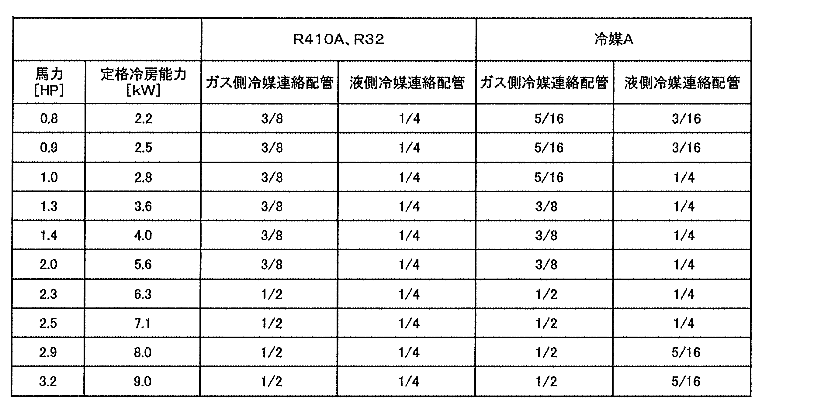
上記第1実施形態では、室内ユニットが1つだけ設けられている空気調和装置を例に挙げて説明したが、空気調和装置としては、互いに並列に接続された複数の室内ユニット(室内膨張弁を有さないもの)が設けられていてもよい。
以下、冷媒回路の概略構成図である図9E、概略制御ブロック構成図である図9Fを参照しつつ、第2実施形態に係る冷凍サイクル装置としての空気調和装置1aについて説明する。
第2実施形態の空気調和装置1aの室外ユニット20では、室外ファン25として、第1室外ファン25aと第2室外ファン25bとが設けられている。空気調和装置1aの室外ユニット20の室外熱交換器23は、第1室外ファン25aおよび第2室外ファン25bから受ける空気流れに対応するように、広い熱交換面積が確保されている。
第2実施形態の室内ユニット30は、対象空間である室内の上方空間に吊り下げられることで設置されるか、天井面に対して設置されるか、壁面に対して設置されて用いられる。室内ユニット30は、液側冷媒連絡配管6およびガス側冷媒連絡配管5を介して室外ユニット20と接続されており、冷媒回路10の一部を構成している。
第2実施形態の上記冷媒X,冷媒Y,冷媒A~冷媒Eが用いられる空気調和装置1aの液側冷媒連絡配管6は、管外径をD0/8インチとして表した場合に、R410AやR32を用いた場合の管外径との関係とは無関係に、D0の範囲を「2≦D0≦4」とすることができる。
第2実施形態の上記冷媒X,冷媒Y,冷媒A~冷媒Eが用いられる空気調和装置1aのガス側冷媒連絡配管5は、管外径をD0/8インチとして表した場合に、R410AやR32を用いた場合の管外径との関係とは無関係に、D0の範囲を「3≦D0≦8」とすることができる。
以上の第2実施形態に係る空気調和装置1aにおいても、第1実施形態に係る空気調和装置1と同様に、冷媒X、冷媒Y、冷媒A、冷媒B、冷媒C、冷媒D、あるいは、冷媒Eが用いられているため、GWPを十分に小さく抑えることが可能になっている。
第2実施形態の空気調和装置1aにおいて、冷媒X,冷媒Y,冷媒A~冷媒Eではなく、冷媒R410AとR32が用いられるとした場合には、一般的に、定格冷房能力の範囲に応じて、以下の表329、表330に示すような管外径(インチ)の液側冷媒連絡配管6およびガス側冷媒連絡配管5が用いられている。
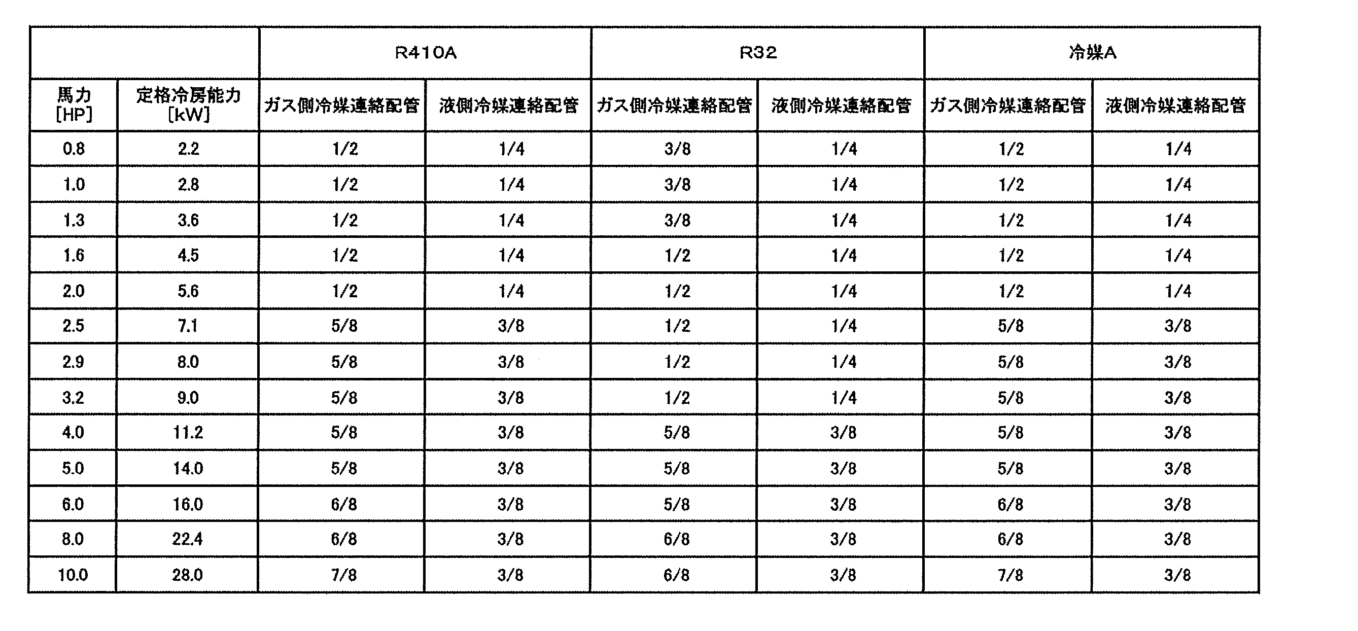
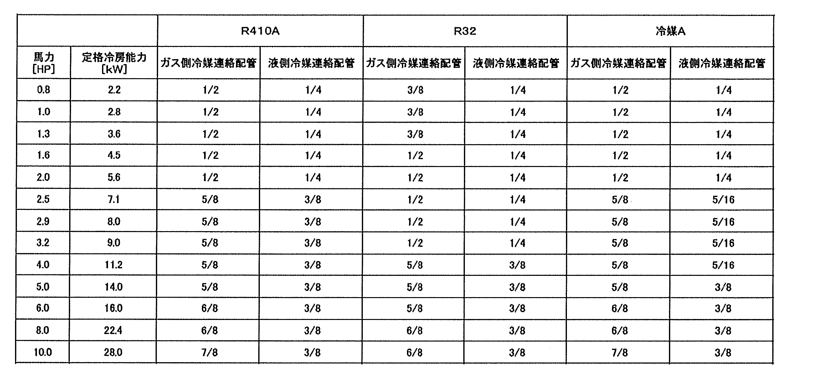
上記第2実施形態では、室内ユニットが1つだけ設けられている空気調和装置を例に挙げて説明したが、空気調和装置としては、互いに並列に接続された複数の室内ユニット(室内膨張弁を有さないもの)が設けられていてもよい。
以下、冷媒回路の概略構成図である図9I、概略制御ブロック構成図である図9Jを参照しつつ、第3実施形態に係る冷凍サイクル装置としての空気調和装置1bについて説明する。
第3実施形態に係る空気調和装置1bの室外ユニット20では、上記第1実施形態における室外ユニット20において、低圧レシーバ26、過冷却熱交換器47および過冷却回路46が設けられている。
また、第3実施形態に係る空気調和装置1bでは、上記第1実施形態における室内ユニット30の代わりに、互いに並列に設けられた第1室内ユニット30および第2室内ユニット35を有している。
第3実施形態の上記冷媒X,冷媒Y,冷媒A~冷媒Eが用いられる空気調和装置1bの液側冷媒連絡配管6は、管外径をD0/8インチとして表した場合に、R410AやR32を用いた場合の管外径との関係とは無関係に、D0の範囲を「2≦D0≦4」とすることができる。
第3実施形態の上記冷媒X,冷媒Y,冷媒A~冷媒Eが用いられる空気調和装置1bのガス側冷媒連絡配管5は、管外径をD0/8インチとして表した場合に、R410AやR32を用いた場合の管外径との関係とは無関係に、D0の範囲を「3≦D0≦8」とすることができる。
以上の第3実施形態に係る空気調和装置1bにおいても、第1実施形態に係る空気調和装置1と同様に、冷媒X、冷媒Y、冷媒A、冷媒B、冷媒C、冷媒D、あるいは、冷媒Eが用いられているため、GWPを十分に小さく抑えることが可能になっている。
第3実施形態の空気調和装置1bにおいて、冷媒X,冷媒Y,冷媒A~冷媒Eではなく、冷媒R410AとR32が用いられるとした場合には、一般的に、定格冷房能力の範囲に応じて、以下の表331、表332に示すような管外径(インチ)の液側冷媒連絡配管6およびガス側冷媒連絡配管5が用いられている。


上記第1実施形態から第3実施形態および各変形例を適宜組み合わせて空気調和装置や室外ユニットを構成してもよい。
(10-1)空調機1の構成
図10Aは、一実施形態に係る圧縮機100が利用される空調機1の冷媒回路図である。空調機1は、圧縮機100を備えた冷凍サイクル装置である。圧縮機100が採用される空調機1として、「冷房運転専用の空調機」、「暖房運転専用の空調機」、及び「四路切換弁を用いて冷房運転および暖房運転のいずれかに切り換え可能な空調機」などが挙げられる。ここでは、「四路切換弁を用いて冷房運転および暖房運転のいずれかに切り換え可能な空調機」を用いて説明する。
室内ユニット2に搭載される室内熱交換器13は、伝熱管と多数の伝熱フィンとにより構成されたクロスフィン式のフィン・アンド・チューブ型熱交換器である。室内熱交換器13は、液側が液冷媒連絡配管4に接続され、ガス側がガス冷媒連絡配管5に接続され、冷房運転時は冷媒の蒸発器として機能する。
室外ユニット3は、アキュムレータ15、圧縮機100、室外熱交換器17、及び膨張弁18を搭載している。
室外熱交換器17は、伝熱管と多数の伝熱フィンとにより構成されたクロスフィン式のフィン・アンド・チューブ型熱交換器である。室外熱交換器17は、その一方が圧縮機100から吐出された冷媒が流れる吐出管24側に接続され、他方が液冷媒連絡配管4側に接続されている。室外熱交換器17は、圧縮機100から吐出管24を介して供給されるガス冷媒の凝縮器として機能する。
膨張弁18は、室外熱交換器17と液冷媒連絡配管4とを接続する配管に設けられている。膨張弁18は、配管を流れる冷媒の圧力や流量の調節を行うための開度調整可能な電動弁である。
アキュムレータ15は、ガス冷媒連絡配管5と圧縮機100の吸入管23とを接続する配管に設けられている。アキュムレータ15は、圧縮機100に液冷媒が供給されることを防止するため、室内熱交換器13からガス冷媒連絡配管5を経て吸入管23に向かう冷媒を、気相と液相とに分離する。圧縮機100には、アキュムレータ15の上部空間に集まる気相の冷媒が供給される。
図10Bは、一実施形態に係る圧縮機100の縦断面図である。図10Bにおいて、圧縮機100は、スクロール圧縮機である。圧縮機100は、吸入管23を介して吸入した冷媒を、圧縮室Scで圧縮し、圧縮後の冷媒を吐出管24から吐出する。なお、圧縮機100については、「(10-2)圧縮機100の構成」の節で詳細を説明する。
四方切換弁16は、第1から第4までのポートを有している。四方切換弁16では、第1ポートが圧縮機100の吐出側に接続され、第2ポートが圧縮機100の吸入側に接続され、第3ポートが室外熱交換器17のガス側端部に接続され、第4ポートがガス側閉鎖弁Vgに接続されている。
図10Bに示すように、圧縮機100は、ケーシング20と、固定スクロール30を含む圧縮機構60と、モータ70と、クランクシャフト80と、下部軸受90とを備えている。
圧縮機100は、縦長円筒状のケーシング20を有する。ケーシング20は、上下が開口した略円筒状の円筒部材21と、円筒部材21の上端および下端にそれぞれ設けられた上蓋22aおよび下蓋22bとを有する。円筒部材21と、上蓋22aおよび下蓋22bとは、気密を保つように溶接により固定されている。
圧縮機構60は、図10Bに示されるように、主に、ハウジング61と、ハウジング61の上方に配置される固定スクロール30と、固定スクロール30と組み合わされて圧縮室Scを形成する可動スクロール40と、を有する。
図10Bに示すように、固定スクロール30は、平板状の固定側鏡板32と、固定側鏡板32の前面(図10Bにおける下面)から突出する渦巻状の固定側ラップ33と、固定側ラップ33を囲む外縁部34とを有する。
可動スクロール40は、図10Bに示すように、平板状の可動側鏡板41と、可動側鏡板41の前面(図10Bにおける上面)から突出する渦巻状の可動側ラップ42と、可動側鏡板41の背面(図10Bにおける下面)から突出する、円筒状に形成されたボス部43とを有する。
ハウジング61は、円筒部材21に圧入され、その外周面において周方向の全体に亘って円筒部材21と固定されている。また、ハウジング61と固定スクロール30とは、ハウジング61の上端面が、固定スクロール30の外縁部34の下面と密着するように、図示しないボルト等により固定されている。
モータ70は、円筒部材21の内壁面に固定された環状の固定子72と、固定子72の内側に、僅かな隙間(エアギャップ)を空けて回転自在に収容された回転子71とを有する。
クランクシャフト80は、モータ70の駆動力を可動スクロール40に伝達する。クランクシャフト80は、円筒部材21の軸心に沿って上下方向に延びるように配置され、モータ70の回転子71と、圧縮機構60の可動スクロール40とを連結する。
下部軸受90は、モータ70の下方に配置される。下部軸受90は、円筒部材21と固定されている。下部軸受90は、クランクシャフト80の下端側の軸受を構成し、クランクシャフト80の主軸82を回転自在に支持する。
圧縮機100の動作について説明する。モータ70が起動すると、回転子71が固定子72に対して回転し、回転子71と固定されたクランクシャフト80が回転する。クランクシャフト80が回転すると、クランクシャフト80と連結された可動スクロール40が固定スクロール30に対して公転する。そして、冷凍サイクルにおける低圧のガス冷媒が、吸入管23を通って、圧縮室Scの周縁側から、圧縮室Scに吸引される。可動スクロール40が公転するのに従い、吸入管23と圧縮室Scとは連通しなくなり、圧縮室Scの容積が減少するのに伴って、圧縮室Scの圧力が上昇し始める。
図10Cは、回転軸に垂直な平面で切断されたモータ70の断面図である。また、図10Dは、回転軸に垂直な平面で切断された回転子71の断面図である。さらに、図10Eは、回転子71の斜視図である。
固定子72は、胴部725と複数の歯部726とを備えている。胴部725は、回転子71の外周径よりも大きな内周径を有する略筒状に形成されている。胴部725は、歯部726と一体に、厚さ0.05mm以上0.5mm以下の薄い電磁鋼板を所定の形状に加工して、所定の枚数を積層することによって形成される。
回転子71は、外観形状が略円柱状に形成され、その中心軸に沿ってクランクシャフト80の主軸82が連結固定されている。回転子71は、回転子コア710と複数の永久磁石712とを有している。回転子71は、永久磁石712が回転子コア710内に埋め込まれている、埋込磁石型回転子である。
回転子コア710は、磁性材料により略円筒状に形成されている。厚さ0.05mm以上0.5mm以下の薄い電磁鋼板711を所定の形状に加工して、所定の枚数を積層することによって形成される。電磁鋼板としては、高速回転時の回転子の耐久性を向上させるため、引張り強さが400MPa以上の複数の高張力電磁鋼板が望ましい。
磁石収容孔713は、回転軸を中心とする円の径方向に対して略直交する方向に扁平な直方体形状の空間である。磁石収容孔713は永久磁石712を埋設可能な形状であれば、貫通していても、底を有していてもよい。
また、非磁性空間714は、磁石収容孔713の端部から屈曲して回転子コア710の外周側に向けて延びている。非磁性空間714は、減磁界が発生したときに、当該減磁界による磁束が永久磁石712を避けて非磁性空間714を通り易くする役割を有しており、非磁性空間714によっても減磁防止が図られる。
ブリッジ715は、非磁性空間714の半径方向外側に位置して磁極どうしを連結している。ブリッジ715の厚みは、高速回転時の耐久性を向上させるために、3mm以上に設定されている。
永久磁石712は、Nd-Fe-B(ネオジウム・鉄・ボロン)を主成分とするネオジウム希土類磁石である。Nd-Fe-B系磁石の保磁力は、温度の影響を受けて劣化するので、圧縮機にNd-Fe-B系磁石を用いたモータを使用する場合、圧縮機内の高温雰囲気(100℃以上)により保磁力は低下する。
(10-5-1)
圧縮機100は、モータ70が永久磁石712を含む回転子71を有するので、モータの回転数を変更することができる容量可変型圧縮機に適している。この場合、(1)で説明したいずれかの冷媒を用いた空調機1において、空調負荷に応じてモータ回転数を変更することができるので、圧縮機100の高効率化が可能である。
回転子71が埋込磁石型回転子である。埋込磁石型回転子は、永久磁石712が回転子71内に埋め込まれている。
回転子71が複数の電磁鋼板711を板厚方向に積層して形成されている。電磁鋼板711の厚みは、0.05mm以上0.5mm以下である。
永久磁石712は、Nd-Fe-B系磁石である。その結果、磁気エネルギー積を大きくすることができるモータ70が実現し、圧縮機100の高効率化が可能となる。
永久磁石712は、重希土類を粒界拡散して形成されている。その結果、永久磁石712の減磁耐力が向上し、少量の重希土類で永久磁石の保持力を高めることができ、圧縮機100の高効率化が可能となる。
永久磁石712は、1質量%以下のディスプロシウムを含有している。その結果、永久磁石712の保持力が向上するので、圧縮機100の高効率化が可能となる。
永久磁石712は、平均結晶粒径が10μm以下である。その結果、永久磁石712の減磁耐力が上がり、圧縮機100の高効率化が可能となる。
永久磁石712が平板状であり、複数の永久磁石712がV字型を成すように回転子71に埋め込まれている。V字型の谷間に位置する部分の保持力は他の部分よりも{1/(4π)}×103[A/m]以上高く設定されている。その結果、永久磁石712の減磁が抑制され、圧縮機100の高効率化が可能となる。
回転子71が、引張り強さが400MPa以上の複数の高張力電磁鋼板を板厚方向に積層して形成されている。その結果、高速回転時の回転子71の耐久性が向上するので、圧縮機100の高効率化が可能となる。
回転子71のブリッジ715の厚みは、3mm以上である。その結果、高速回転時の回転子の耐久性が向上するので、圧縮機の高効率化が可能となる。
(10-6-1)
回転子71が複数の板状のアモルファス金属を板厚方向に積層して形成されてもよい。この場合、鉄損が少なく効率の高いモータが実現されるので、圧縮機の高効率化が可能となる。
回転子71が、5質量%以上のシリコンを含有する複数の電磁鋼板を板厚方向に積層して形成されてもよい。この場合、適量のシリコンを含有させてヒステリシスを低減させた電磁鋼板により、鉄損が少なく効率の高いモータが実現されるので、圧縮機の高効率化が可能となる。
上記実施形態では、回転子71が埋込磁石型回転子として説明してきたが、これに限定されるものではない。例えば、永久磁石が回転子の表面に張り付けられている、表面磁石型回転子であってもよい。
第1実施形態では、圧縮機100としてスクロール圧縮機を説明したが、圧縮機はスクロール圧縮機に限定されるものではない。
圧縮機300は、縦長円筒状のケーシング220を有する。ケーシング220は、上下が開口した略円筒状の円筒部材221と、円筒部材221の上端および下端にそれぞれ設けられた上蓋222aおよび下蓋222bとを有する。円筒部材221と、上蓋22aおよび下蓋22bとは、気密を保つように溶接により固定されている。
モータ270は、固定子272および回転子271を有している。モータ270は、ロータリ圧縮機である圧縮機300に使用されているという以外は、基本的に第1実施形態のモータ70と同等であり、第1実施形態のモータ70と同等の性能、作用・効果を発揮する。したがって、ここでは、モータ270の説明を省略する。
クランクシャフト280は、回転子271に固定されている。さらに、クランクシャフト280は、上部軸受263および下部軸受290によって、回転軸心Rsを中心として回転できるように支持されている。クランクシャフト280は偏心部241を有している。
圧縮機構260は、単一のシリンダ230と、当該シリンダ230の中に設置された単一のピストン242を有している。シリンダ230は、所定の容積を有し、ケーシング220に固定されている。
ケーシング220の下部には、油溜まり空間Soが設けられている。油溜まり空間Soには、圧縮機構260を潤滑するための冷凍機油Oが溜められる。なお、冷凍機油Oは、上述の冷凍機油を言う。
圧縮機300の動作について説明する。モータ270が起動すると、回転子271が固定子272に対して回転し、回転子271と固定されたクランクシャフト280が回転する。クランクシャフト280が回転すると、クランクシャフト280と連結されたピストン242がシリンダ230に対して公転する。そして、冷凍サイクルにおける低圧のガス冷媒が、吸入管223を通って圧縮室Scに吸引される。ピストン242が公転するのに従い、吸入管223と圧縮室Scとは連通しなくなり、圧縮室Scの容積が減少するのに伴って、圧縮室Scの圧力が上昇し始める。
(10-9-1)
圧縮機300は、第1実施形態のモータ70と同等のモータ270を採用しているので、モータの回転数を変更することができる容量可変型圧縮機に適している。この場合、(1)で説明したいずれかの冷媒を用いた空調機1において、空調負荷に応じてモータ回転数を変更することができるので、圧縮機300の高効率化が可能である。
圧縮機300は、第1実施形態のモータ70と同等のモータ270を採用しているので、第1実施形態の「(10-5)特徴」の「(10-5-2)~(10-5-10)の特徴」を有している。
空調機1の圧縮機として、にロータリ圧縮機である圧縮機300を使用する場合は、スクロール圧縮機を使用する場合に比べて冷媒充填量を少なくすることができるので、可燃性冷媒を使用する空調機に適している。
圧縮機300は、第1実施形態のモータ70と同等のモータ270を採用しているので、第1実施形態の「(10-6)変形例」に記載の全てに変形例の適用が可能である。
圧縮機の形態としては、モータ70と同等のモータを使用する限り、スクリュー圧縮機、或いは、ターボ圧縮機でもよい。
(11-1)第1実施形態
以下、冷媒回路の概略構成図である図11A、概略制御ブロック構成図である図11Bを参照しつつ、第1実施形態に係る冷凍サイクル装置としての空気調和装置1について説明する。
室外ユニット20は、図11Cに示すように、外観が略直方体箱状の室外筐体50により構成されている。この室外ユニット20は、図11Dに示すように、仕切板50aによって内部空間が左右に分割されることで、送風機室および機械室が形成されている。
室内ユニット30は、対象空間である室内の壁面等に設置されている。室内ユニット30は、液側冷媒連絡配管6およびガス側冷媒連絡配管5を介して室外ユニット20と接続されており、冷媒回路10の一部を構成している。
空気調和装置1では、室外ユニット制御部27と室内ユニット制御部34が通信線を介して接続されることで、空気調和装置1の動作を制御するコントローラ7が構成されている。
以下、運転モードについて説明する。
空気調和装置1では、冷房運転モードでは、四路切換弁22の接続状態を圧縮機21の吐出側と室外熱交換器23とを接続しつつ圧縮機21の吸入側とガス側閉鎖弁28とを接続する冷房運転接続状態とし、冷媒回路10に充填されている冷媒を、主として、圧縮機21、室外熱交換器23、室外膨張弁24、室内熱交換器31の順に循環させる。
空気調和装置1では、暖房運転モードでは、四路切換弁22の接続状態を圧縮機21の吐出側とガス側閉鎖弁28とを接続しつつ圧縮機21の吸入側と室外熱交換器23とを接続する暖房運転接続状態とし、冷媒回路10に充填されている冷媒を、主として、圧縮機21、室内熱交換器31、室外膨張弁24、室外熱交換器23の順に循環させる。
上述の空気調和装置1では、冷媒X、冷媒Y、冷媒A、冷媒B、冷媒C、冷媒D、あるいは、冷媒Eが用いられているため、GWPを十分に小さく抑えることが可能になっている。
上記第1実施形態では、室内ユニットが1つだけ設けられている空気調和装置を例に挙げて説明したが、空気調和装置としては、互いに並列に接続された複数の室内ユニット(室内膨張弁を有さないもの)が設けられていてもよい。
以下、冷媒回路の概略構成図である図11G、概略制御ブロック構成図である図11Hを参照しつつ、第2実施形態に係る冷凍サイクル装置としての空気調和装置1aについて説明する。
第2実施形態の空気調和装置1aの室外ユニット20では、室外ファン25として、第1室外ファン25aと第2室外ファン25bとが設けられている。空気調和装置1aの室外ユニット20の室外熱交換器23は、第1室外ファン25aおよび第2室外ファン25bから受ける空気流れに対応するように、広い熱交換面積が確保されている。
第2実施形態の室内ユニット30は、対象空間である室内の上方空間に吊り下げられることで設置されるか、天井面に対して設置される。室内ユニット30は、液側冷媒連絡配管6およびガス側冷媒連絡配管5を介して室外ユニット20と接続されており、冷媒回路10の一部を構成している。
以上の第2実施形態に係る空気調和装置1aにおいても、第1実施形態に係る空気調和装置1と同様に、冷媒X、冷媒Y、冷媒A、冷媒B、冷媒C、冷媒D、あるいは、冷媒Eが用いられているため、GWPを十分に小さく抑えることが可能になっている。
上記第2実施形態では、室内ユニットが1つだけ設けられている空気調和装置を例に挙げて説明したが、空気調和装置としては、互いに並列に接続された複数の室内ユニット(室内膨張弁を有さないもの)が設けられていてもよい。
以下、冷媒回路の概略構成図である図11M、概略制御ブロック構成図である図11Nを参照しつつ、第3実施形態に係る冷凍サイクル装置としての空気調和装置1bについて説明する。
第3実施形態に係る空気調和装置1bの室外ユニット20では、上記第1実施形態における室外ユニット20において、低圧レシーバ26、過冷却熱交換器47および過冷却回路46が設けられている。
また、第3実施形態に係る空気調和装置1bでは、上記第1実施形態における室内ユニット30の代わりに、互いに並列に設けられた第1室内ユニット30および第2室内ユニット35を有している。
以上の第3実施形態に係る空気調和装置1bにおいても、第1実施形態に係る空気調和装置1と同様に、冷媒X、冷媒Y、冷媒A、冷媒B、冷媒C、冷媒D、あるいは、冷媒Eが用いられているため、GWPを十分に小さく抑えることが可能になっている。
上記第1実施形態から第3実施形態および各変形例を適宜組み合わせて空気調和装置や室外ユニットを構成してもよい。
(12-1)空調機1の構成
図12Aは、一実施形態に係る圧縮機100が利用される空調機1の冷媒回路図である。空調機1は、圧縮機100を備えた冷凍サイクル装置である。圧縮機100が採用される空調機1として、「冷房運転専用の空調機」、「暖房運転専用の空調機」、及び「四路切換弁を用いて冷房運転および暖房運転のいずれかに切り換え可能な空調機」などが挙げられる。ここでは、「四路切換弁を用いて冷房運転および暖房運転のいずれかに切り換え可能な空調機」を用いて説明する。
室内ユニット2に搭載される室内熱交換器13は、伝熱管と多数の伝熱フィンとにより構成されたクロスフィン式のフィン・アンド・チューブ型熱交換器である。室内熱交換器13は、液側が液冷媒連絡配管4に接続され、ガス側がガス冷媒連絡配管5に接続され、冷房運転時は冷媒の蒸発器として機能する。
室外ユニット3は、アキュムレータ15、圧縮機100、室外熱交換器17、及び膨張弁18を搭載している。
室外熱交換器17は、伝熱管と多数の伝熱フィンとにより構成されたクロスフィン式のフィン・アンド・チューブ型熱交換器である。室外熱交換器17は、その一方が圧縮機100から吐出された冷媒が流れる吐出管24側に接続され、他方が液冷媒連絡配管4側に接続されている。室外熱交換器17は、圧縮機100から吐出管24を介して供給されるガス冷媒の凝縮器として機能する。
膨張弁18は、室外熱交換器17と液冷媒連絡配管4とを接続する配管に設けられている。膨張弁18は、配管を流れる冷媒の圧力や流量の調節を行うための開度調整可能な電動弁である。
アキュムレータ15は、ガス冷媒連絡配管5と圧縮機100の吸入管23とを接続する配管に設けられている。アキュムレータ15は、圧縮機100に液冷媒が供給されることを防止するため、室内熱交換器13からガス冷媒連絡配管5を経て吸入管23に向かう冷媒を、気相と液相とに分離する。圧縮機100には、アキュムレータ15の上部空間に集まる気相の冷媒が供給される。
図12Bは、一実施形態に係る圧縮機100の縦断面図である。図12Bにおいて、圧縮機100は、スクロール圧縮機である。圧縮機100は、吸入管23を介して吸入した冷媒を、圧縮室Scで圧縮し、圧縮後の冷媒を吐出管24から吐出する。なお、圧縮機100については、「(12-2)圧縮機100の構成」の節で詳細を説明する。
四方切換弁16は、第1から第4までのポートを有している。四方切換弁16では、第1ポートが圧縮機100の吐出側に接続され、第2ポートが圧縮機100の吸入側に接続され、第3ポートが室外熱交換器17のガス側端部に接続され、第4ポートがガス側閉鎖弁Vgに接続されている。
圧縮機100は、蒸発器や、凝縮器、膨張機構などと共に冷媒回路を構成し、その冷媒回路中のガス冷媒を圧縮する役割を担うものである。図12Bに示されるように、圧縮機100は、主に、縦長円筒状の密閉ドーム型のケーシング20、モータ70、圧縮機構60、オルダムリング39、下部軸受90、吸入管23、および吐出管24から構成されている。
ケーシング20は、略円筒状の円筒部材21と、円筒部材21の上端部に気密状に溶接される椀状の上蓋22aと、円筒部材21の下端部に気密状に溶接される椀状の下蓋22bとを有している。
モータ70は、誘導モータであって、主に、ケーシング20の内壁面に固定された環状の固定子72と、固定子72の内側に僅かな隙間(エアギャップ)をもって回転自在に収容された回転子71とから構成されている。
圧縮機構60は、図12Bに示されるように、主に、ハウジング61と、ハウジング61の上方に密着して配置される固定スクロール30と、固定スクロール30に噛合する可動スクロール40とから構成されている。
固定スクロール30は、図12Bに示されるように、主に、鏡板34と、鏡板34の下面に形成された渦巻き状(インボリュート状)のラップ33とから構成されている。
可動スクロール40は、図12Bに示されるように、主に、鏡板41と、鏡板41の上面に形成された渦巻き状(インボリュート状)のラップ42と、鏡板41の下面に形成されたボス部43とから構成されている。
ハウジング61は、その外周面において周方向の全体に亘って円筒部材21に圧入固定されている。つまり、円筒部材21とハウジング61とは全周に亘って気密状に密着されている。このため、ケーシング20の内部は、ハウジング61下方の高圧空間とハウジング61上方の低圧空間とに区画されていることになる。また、このハウジング61には、上面中央に凹設されたハウジング凹部61aと、下面中央から下方に延設された軸受部61bとが形成されている。軸受部61bには、上下方向に貫通する軸受孔63が形成されており、クランクシャフト80が軸受孔63を介して回転自在に嵌入されている。
オルダムリング39は、可動スクロール40の自転運動を防止するための部材であって、ハウジング61に形成されるオルダム溝(図示せず)に嵌め込まれている。なお、このオルダム溝は、長円形状の溝であって、ハウジング61において互いに対向する位置に配設されている。
下部軸受90は、モータ70の下方の下部空間に配設されている。この下部軸受90は、円筒部材21に固定されるとともにクランクシャフト80の下端側軸受を構成し、クランクシャフト80を支持している。
吸入管23は、冷媒回路の冷媒を圧縮機構60に導くためのものであって、ケーシング20の上蓋22aに気密状に嵌入されている。吸入管23は、低圧空間Slを上下方向に貫通すると共に、内端部が固定スクロール30に嵌入されている。
吐出管24は、ケーシング20内の冷媒をケーシング20外に吐出させるためのものであって、ケーシング20の円筒部材21に気密状に嵌入されている。そして、この吐出管24は、上下方向に延びる円筒形状に形成されハウジング61の下端部に固定される内端部36を有している。なお、吐出管24の内端開口、即ち流入口は、下方に向かって開口されている。
モータ70が駆動されると、クランクシャフト80が回転し、可動スクロール40が自転することなく公転運転を行う。すると、低圧のガス冷媒が、吸入管23を通って圧縮室Scの周縁側から圧縮室Scに吸引され、圧縮室Scの容積変化に伴って圧縮され、高圧のガス冷媒となる。
図12Cは、回転軸に垂直な平面で切断されたモータ70の断面図である。また、図12Dは、回転軸に垂直な平面で切断された回転子71の断面図である。さらに、図12Eは、回転子71の斜視図である。
固定子72は、胴部725と複数の歯部726とを備えている。胴部725は、回転子71の外周径よりも大きな内周径を有する略筒状に形成されている。胴部725は、厚さ0.05mm以上0.5mm以下の薄い電磁鋼板を所定の形状に加工して、所定の枚数を積層することによって形成される。
回転子71は、かご型回転子である。回転子71は、略円柱状の外観形状に形成され、その中心軸に沿ってクランクシャフト80の主軸82が連結固定される。回転子71は、回転子コア710と、複数の導体棒716と、端絡環717とを有している。
回転子コア710は、磁性材料により略円筒状に形成されている。厚さ0.05mm以上0.5mm以下の薄い電磁鋼板を所定の形状に加工して、図12Eに示すように、所定の枚数を積層することによって形成される。
導体棒形成孔718に充填される導体棒716と、回転子コア710を両端から挟む端絡環717とは、一体に成形される。例えば、導体としてアルミニウム又はアルミニウム合金を採用する場合、回転子コア710がアルミダイカスト金型にセットされた後、溶融したアルミニウム又はアルミニウム合金が型内に圧入されることによって、一体的に成形される。
圧縮機100は、(1)で説明したいずれかの冷媒を圧縮する圧縮機であって、誘導モータ70を採用することによって、比較的低コストで高出力化が可能となる。
(12-6-1)第1変形例
上記実施形態では、導体棒716と端絡環717とがアルミニウム又はアルミニウム合金で一体に成形される態様で説明したが、これに限定されるものではない。
図12Fは、第2変形例に係る圧縮機100の誘導モータ70に使用される回転子71の斜視図である。図12Fにおいて、回転子71は、放熱構造としてのヒートシンク717aを有している。
図12Gは、第3変形例に係る圧縮機100が利用される空調機1の冷媒回路図である。図12Gにおいて、図12Aとの違いは、冷媒回路11が分岐回路110を含む冷却構造を有している点であり、それ以外は、図12Aと同じ構成である。
第1実施形態では、圧縮機100としてスクロール圧縮機を説明したが、圧縮機はスクロール圧縮機に限定されるものではない。
圧縮機300は、縦長円筒状のケーシング220を有する。ケーシング220は、上下が開口した略円筒状の円筒部材221と、円筒部材221の上端および下端にそれぞれ設けられた上蓋222aおよび下蓋222bとを有する。円筒部材221と、上蓋22aおよび下蓋22bとは、気密を保つように溶接により固定されている。
モータ270は、固定子272および回転子271を有している。モータ270は、ロータリ圧縮機である圧縮機300に使用されているという以外は、基本的に第1実施形態のモータ70と同等であり、第1実施形態のモータ70と同等の性能、作用・効果を発揮する。したがって、ここでは、モータ270の説明を省略する。
クランクシャフト280は、回転子271に固定されている。さらに、クランクシャフト280は、上部軸受263および下部軸受290によって、回転軸心Rsを中心として回転できるように支持されている。クランクシャフト280は偏心部241を有している。
圧縮機構260は、単一のシリンダ230と、当該シリンダ230の中に設置された単一のピストン242を有している。シリンダ230は、所定の容積を有し、ケーシング220に固定されている。
ケーシング220の下部には、油溜まり空間Soが設けられている。油溜まり空間Soには、圧縮機構260を潤滑するための冷凍機油Oが溜められる。なお、冷凍機油Oは、上述の冷凍機油を言う。
圧縮機300の動作について説明する。モータ270が起動すると、回転子271が固定子272に対して回転し、回転子271と固定されたクランクシャフト280が回転する。クランクシャフト280が回転すると、クランクシャフト280と連結されたピストン242がシリンダ230に対して公転する。そして、冷凍サイクルにおける低圧のガス冷媒が、吸入管223を通って圧縮室Scに吸引される。ピストン242が公転するのに従い、吸入管223と圧縮室Scとは連通しなくなり、圧縮室Scの容積が減少するのに伴って、圧縮室Scの圧力が上昇し始める。
(12-9-1)
圧縮機300は、(1)で説明したいずれかの冷媒を圧縮する圧縮機であって、モータ270に誘導モータを採用することによって、比較的低コストで高出力化が可能となる。
空調機1の圧縮機として、ロータリ圧縮機である圧縮機300を使用する場合は、スクロール圧縮機を使用する場合に比べて冷媒充填量を少なくすることができるので、可燃性冷媒を使用する空調機に適している。
圧縮機300は、第1実施形態のモータ70と同等のモータ270を採用しているので、第1実施形態の「(12-6)変形例」に記載の全てに変形例の適用が可能である。
圧縮機の形態としては、モータ70と同等のモータを使用する限り、スクリュー圧縮機、或いは、ターボ圧縮機でもよい。
(13-1)第1実施形態
図13Aは、本開示の第1実施形態に係る空調機1の構成図である。図13Aにおいて、空調機1は、利用ユニット2と熱源ユニット3とによって構成されている。
空調機1は、圧縮機100、四路切換弁16,熱源側熱交換器17、減圧機構としての膨張弁18、及び利用側熱交換器13が、冷媒配管によって環状に接続された冷媒回路11を有している。
冷媒回路11のうち、利用側熱交換器13は利用ユニット2に属している。また、利用ユニット2には、利用側ファン14が搭載されている。利用側ファン14は、利用側熱交換器13への空気の流れを生成する。
冷媒回路11のうちの圧縮機100、四路切換弁16,熱源側熱交換器17、及び膨張弁18は熱源ユニット3に属している。また、熱源ユニット3には、熱源側ファン19が搭載されている。熱源側ファン19は、熱源側熱交換器17への空気の流れを生成する。
電力変換装置30は、図13Aに示すように、熱源ユニット3側に搭載されている。電力変換装置30は、図13Bに示すように、電源回路20、インバータ25と、ゲート駆動回路26と、熱源側マイクロコンピュータ42とで構成されている。電源回路20は、整流回路21と、コンデンサ22とで構成されている。
整流回路21は、4つのダイオードD1a,D1b,D2a,D2bによってブリッジ状に構成されている。具体的には、ダイオードD1aとD1b、D2aとD2bは、それぞれ互いに直列に接続されている。ダイオードD1a,D2aの各カソード端子は、共にコンデンサ22のプラス側端子に接続されており、整流回路21の正側出力端子として機能する。ダイオードD1b,D2bの各アノード端子は、共にコンデンサ22のマイナス側端子に接続されており、整流回路21の負側出力端子として機能する。
コンデンサ22は、一端が整流回路21の正側出力端子に接続され、他端が整流回路21の負側出力端子に接続されている。コンデンサ22は、整流回路21によって整流された電圧を平滑する程の大きな静電容量を有しない、小容量のコンデンサである。以下、説明の便宜上、コンデンサ22の端子間電圧をDCバス電圧Vdcという。
電圧検出器23は、コンデンサ22の出力側に接続されており、コンデンサ22の両端電圧、即ちDCバス電圧Vdcの値を検出するためのものである。電圧検出器23は、例えば、互いに直列に接続された2つの抵抗がコンデンサ22に並列接続され、DCバス電圧Vdcが分圧されるように構成される。それら2つの抵抗同士の接続点の電圧値は、熱源側マイクロコンピュータ42に入力される。
電流検出器24は、コンデンサ22及びインバータ25の間であって、かつコンデンサ22の負側出力端子側に接続されている。電流検出器24は、モータ70の起動後、モータ70に流れるモータ電流を三相分の電流の合計値として検出する。
インバータ25は、モータ70のU相、V相及びW相の各相巻線Lu,Lv,Lwそれぞれに対応する3つの上下アームが互いに並列に、且つコンデンサ22の出力側に接続されている。
ゲート駆動回路26は、熱源側マイクロコンピュータ42からの指令電圧に基づき、インバータ25の各トランジスタQ3a~Q5bのオン及びオフの状態を変化させる。具体的には、ゲート駆動回路26は、熱源側マイクロコンピュータ42によって決定されたデューティを有するパルス状の駆動電圧SU,SV,SWがインバータ25からモータ70に出力されるように、各トランジスタQ3a~Q5bのゲートに印加するゲート制御電圧Gu,Gx,Gv,Gy,Gw,Gzを生成する。生成されたゲート制御電圧Gu,Gx,Gv,Gy,Gw,Gzは、それぞれのトランジスタQ3a~Q5bのゲート端子に印加される。
熱源側マイクロコンピュータ42は、電圧検出器23、電流検出器24、及びゲート駆動回路26と接続されている。本実施形態では、熱源側マイクロコンピュータ42は、モータ70をロータ位置センサレス方式にて駆動させている。なお、ロータ位置センサレス方式に限定されるものではないので、センサ方式で行なってもよい。
(13-1-3-1)
(1)で説明したいずれかの冷媒を用いた空調機1において、必要に応じ、電力変換装置30を介してモータ70の回転数を変更することができる。言い換えると、空調負荷に応じて圧縮機100のモータ回転数を変更することができるので、高い通年エネルギー消費効率[Annual Performance Factor (APF)]を実現することができる。
また、整流回路21の出力側に電解コンデンサを要しないので、回路の大型化、高コスト化が抑制される。
図13Cは、第1実施形態の変形例における電力変換装置130の回路ブロック図である。図13Cにおいて、本変形例と上記第1実施形態との相違点は、単相交流電源90に替えて三相交流電源190に対応することができるように、単相用の整流回路21に替えて三相用の整流回路121を採用している点である。
(13-1-5-1)
(1)で説明したいずれかの冷媒を用いた空調機1において、必要に応じ、電力変換装置130を介してモータ70の回転数を変更することができる。言い換えると、空調負荷に応じて圧縮機100のモータ回転数を変更することができるので、高い通年エネルギー消費効率[Annual Performance Factor (APF)]を実現することができる。
また、整流回路121の出力側に電解コンデンサを要しないので、回路の大型化、高コスト化が抑制される。
図13Dは、本開示の第2実施形態に係る空調機に搭載される電力変換装置30Bの回路ブロック図である。
図13Dにおいて、電力変換装置30Bは、インダイレクトマトリックスコンバータである。図13Bの第1実施形態の電力変換装置30との相違点は、整流回路21に替えてコンバータ27を採用し、ゲート駆動回路28と、リアクタ33を新たに追加している点であり、これら以外は、第1実施形態と同様である。
図13Dにおいて、コンバータ27は、複数のIGBT(絶縁ゲート型バイポーラトランジスタ、以下、単にトランジスタという)Q1a,Q1b,Q2a,Q2b及び複数のダイオードD1a,D1b,D2a,D2bを含んでいる。
ゲート駆動回路28は、熱源側マイクロコンピュータ42からの指令電圧に基づき、コンバータ27の各トランジスタQ1a~Q2bのオン及びオフの状態を変化させる。具体的には、ゲート駆動回路28は、交流電源90から熱源側に流れる電流を所定の値に制御するよう熱源側マイクロコンピュータ42によって決定されたデューティを有するパルス状のゲート制御電圧Pq,Pr,Ps,Ptを生成する。生成されたゲート制御電圧Pq,Pr,Ps,Ptは、それぞれのトランジスタQ1a~Q2bのゲート端子に印加される。
リアクタ33は、交流電源90とコンバータ27との間に交流電源90と直列に接続されている。具体的には、その一端が交流電源90の1つの極に接続され、他端がコンバータ27の1つの入力端に接続されている。
熱源側マイクロコンピュータ42は、コンバータ27の上下アームのトランジスタQ1a,Q1bまたはトランジスタQ2a,Q2bをオン・オフすることで、所定時間だけ短絡・開放させ、例えば電流を略正弦波状に制御することによって、電源入力力率の改善や高調波成分の抑制を行う。
空調機1は、高効率な上に、コンバータ27の出力側に電解コンデンサを要しないので回路の大型化、高コスト化が抑制される。
図13Eは、第2実施形態の変形例における電力変換装置130Bの回路ブロック図である。図13Eにおいて、本変形例と上記第2実施形態との相違点は、単相交流電源90に替えて三相交流電源190に対応することができるように、単相用のコンバータ27に替えて三相用のコンバータ127を採用している点である。また、単相用のコンバータ27から三相用のコンバータ127への変更に伴い、ゲート駆動回路28に替えてゲート駆動回路128を採用している点である。さらに、各相の出力側とコンバータ127との間にリアクタ33が接続されている。なお、リアクタ33の入力側端子間にコンデンサを接続しているが、外すことも可能である。
コンバータ127は、複数のIGBT(絶縁ゲート型バイポーラトランジスタ、以下、単にトランジスタという)Q0a,Q0b,Q1a,Q1b,Q2a,Q2b及び複数のダイオードD0a,D0b,D1a,D1b,D2a,D2bを含んでいる。
ゲート駆動回路128は、熱源側マイクロコンピュータ42からの指令電圧に基づき、コンバータ127の各トランジスタQ0a~Q2bのオン及びオフの状態を変化させる。具体的には、ゲート駆動回路128は、交流電源190から熱源側に流れる電流を所定の値に制御するよう熱源側マイクロコンピュータ42によって決定されたデューティを有するパルス状のゲート制御電圧Po,Pp,Pq,Pr,Ps,Ptを生成する。生成されたゲート制御電圧Po,Pp,Pq,Pr,Ps,Ptは、それぞれのトランジスタQ0a~Q2bのゲート端子に印加される。
空調機1は、高効率な上に、コンバータ127の出力側に電解コンデンサを要しないので回路の大型化、高コスト化が抑制される。
図13Fは、本開示の第3実施形態に係る空調機に搭載される電力変換装置30Cの回路ブロック図である。
図13Fにおいて、電力変換装置30Cは、マトリックスコンバータ29である。
マトリックスコンバータ29は、交流電源90からの入力の一端には双方向スイッチS1a,S2a,S3aを接続し、他方の一端には双方向スイッチS1b,S2b,S3bを接続することによって構成されている。
図13Gは、双方向スイッチを概念的に示す回路図である。図13Gにおいて、トランジスタQ61,Q62と、ダイオードD61,D62と、端子Ta,Tbを有している。トランジスタQ61,Q62は、絶縁ゲート型バイポーラトランジスタ(IGBT:Insulated Gate Bipolar Transistor)である。
図13Hは、マトリックスコンバータ29の電流方向の一例を示した回路図である。交流電源90からマトリックスコンバータ29を通じ、モータ70へと流れる電流の経路の一例を示している。交流電源90の一つの極から双方向スイッチS1aを通して、モータ70の3相巻線の一つであるU相巻線LuからW相巻線Lwを経て、双方向スイッチS3bを通り、交流電源90の他の極へと電流は流れる。これによって、モータ70へ電力が供給されモータ70が駆動される。
空調機1は、高効率な上に、マトリックスコンバータ29の出力側に電解コンデンサを要しないので回路の大型化、高コスト化が抑制される。
図13Jは、第3実施形態の変形例における電力変換装置130Cの回路ブロック図である。図13Jにおいて、本変形例と上記第3実施形態との相違点は、単相交流電源90に替えて三相交流電源190に対応することができるように、単相用のマトリックスコンバータ29に替えて三相用のマトリックスコンバータ129を採用している点である。
また、単相用のマトリックスコンバータ29から三相用のマトリックスコンバータ129への変更に伴い、ゲート駆動回路31に替えてゲート駆動回路131を採用している点も相違点である。さらに、各相の出力側とマトリックスコンバータ129との間にリアクタL1,L2,L3が接続されている。
また、電力変換装置30では、入力端子と出力端子との間にクランプ回路133が接続されているので、双方向スイッチS1a~S3bのスイッチングによってマトリックスコンバータ129の入力端子と出力端子との間に生じるサージ電圧を、クランプ回路133内のコンデンサ(図13I参照)で吸収することができる。
空調機1は、高効率な上に、マトリックスコンバータ129の出力側に電解コンデンサを要しないので回路の大型化、高コスト化が抑制される。
(13-4-1)
空調機1の圧縮機100は、スクロール圧縮機、ロータリー圧縮機、ターボ圧縮機、およびスクリュー圧縮機のいずれかが採用される。
圧縮機100のモータ70は、永久磁石を含む回転子71を有する永久磁石同期モータである。
(14-1)
図14Aは、本開示の一実施形態に係る空調機1の構成図である。図14Aにおいて、空調機1は、利用ユニット2と熱源ユニット3とによって構成されている。
空調機1は、圧縮機100、四路切換弁16,熱源側熱交換器17、減圧機構としての膨張弁18、及び利用側熱交換器13が、冷媒配管によって環状に接続された冷媒回路11を有している。
冷媒回路11のうち、利用側熱交換器13は利用ユニット2に属している。また、利用ユニット2には、利用側ファン14が搭載されている。利用側ファン14は、利用側熱交換器13への空気の流れを生成する。
冷媒回路11のうちの圧縮機100、四路切換弁16,熱源側熱交換器17、及び膨張弁18は熱源ユニット3に属している。また、熱源ユニット3には、熱源側ファン19が搭載されている。熱源側ファン19は、熱源側熱交換器17への空気の流れを生成する。
図14Bは、圧縮機100のモータ70の運転回路図である。図14Bにおいて、接続部30は、交流電源90から圧縮機100のモータ70へと周波数変換をさせずに電力を供給させる回路である。
上記のように構成された圧縮機100の運転回路において、交流電源90が投入されると、補助巻線728に正特性サーミスタ21を通じて電流が流れ、モータ70が起動する。
(14-1-4-1)
(1)で説明したいずれかの冷媒を使用した空調機1において、交流電源90とモータ70との間に電力変換装置を介在させずに圧縮機100を駆動することができるので、比較的安価な構成で、環境保護に配慮した空調機1を提供することができる。
(1)で説明したいずれかの冷媒を使用した空調機1において、正特性サーミスタ21と運転コンデンサ22との並列回路である起動回路20を補助巻線728に接続したことによって、圧縮機100のモータ70の起動トルクを大きくとることができる。
モータ70が誘導モータであり、比較的低コストで高出力が可能であるので、空調機1の高効率化が可能である。
図14Cは、変形例に係る空調機1における圧縮機200のモータ170の運転回路図である。図14Cにおいて、モータ170は、三相誘導モータであって、接続部130を介して三相交流電源190に接続されている。
(14-1-6-1)
(1)で説明したいずれかの冷媒を使用した空調機1において、三相交流電源190とモータ170との間に電力変換装置を介在させずに圧縮機200を駆動することができるので、比較的安価な構成で、環境保護に配慮した空調機1を提供することができる。
モータ170が誘導モータであり、比較的低コストで高出力が可能であるので、空調機1の高効率化が可能である。
(15-1)第1実施形態
第1実施形態に係る温水製造装置である給湯システム1は、図15A~図15Cに示すように、ヒートポンプ2、貯湯ユニット3、これらの管理や制御を行うコントローラ50、ユーザーへの情報表示やユーザーの操作受付を担うリモコン90、などを備えている。
ヒートポンプ2は、水を加熱するための熱源装置として機能するユニットであり、冷媒が循環する冷媒回路20、送風ファン24F、各種センサ、などを備えている。本実施形態では、冷媒回路20には、蒸気圧縮式の冷凍サイクルを行うための冷媒が充填されている。当該冷媒は、(1)で説明したいずれかの冷媒であり、上述した冷媒X,冷媒Y,冷媒A~冷媒Eのいずれかを用いることができる。
貯湯ユニット3は、市水(水道水)などの外部から供給される水を、ヒートポンプ2に送って加熱させ、ヒートポンプ2から戻ってきた水(湯)を蓄えるユニットである。また、貯湯ユニット3は、ユーザーが設定する温度の湯が供給されるように、燃焼加熱装置4や混合弁77によって温度調整された湯を給湯部82に送る機能を持つ。
取水部81は、接続口を有し、市水(水道水)の供給管89aが接続される。
貯湯タンク35は、ヒートポンプ2によって加熱された水(湯)を、ユーザーが蛇口99を回して利用する前から予め蓄えておくタンクである。貯湯タンク35は、水が常に満たされている。そして、貯湯タンク35には、所定温度以上、ここでは70℃以上の高温の水(以下、高温水という。)の量をコントローラ50に把握させるための、タンク温度分布検知センサが設けられている。タンク温度分布検知センサは、貯湯タンク35の下部から上部に向かって、順に、第1センサT1、第2センサT2、第3センサT3、第4センサT4、第5センサT5、第6センサT6の6つにより構成される。コントローラ50は、これらのタンク温度分布検知センサT1~T6が検知する貯湯タンク35内の各高さ位置での水温およびリモコン90による設定に基づき、ヒートポンプ2を駆動させて沸き上げ運転を行う。沸き上げ運転とは、貯湯タンク35の中の水の温度が目的の温度に到達するまで水の熱量を上げていく運転である。沸き上げ運転における目的の温度、すなわち、貯湯タンク35の中の水の目標貯湯温度は、例えば予め給湯システム1の製造工場において設定されている。本実施形態では、目標貯湯温度は75℃である。
循環水配管30は、貯湯タンク35の中の水にヒートポンプ2で得られる熱を伝えるための回路であり、往き管31、水熱交換器22内の水管32w、戻り管33、および、循環用ポンプ34を有している。往き管31は、貯湯タンク35の下端近傍と水熱交換器22内の水管32wの上流側端部とを接続している。戻り管33は、水熱交換器22内の水管32wの下流側端部と貯湯タンク35の上端近傍とを接続している。循環用ポンプ34は、往き管31の途中に設けられている。循環用ポンプ34は、出力を調整することができる電動ポンプであり、貯湯タンク35と水熱交換器22との間で水を循環させる役割を果たす。具体的には、循環水配管30では、循環用ポンプ34がコントローラ50からの指令を受けて駆動することにより、貯湯タンク35内の水のうち下部に存在している温度の低い水が、往き管31に流出し、水熱交換器22内の水管32wを通過することで温度上昇し、戻り管33を介して貯湯タンク35の上端近傍に戻ってくる。これにより、貯湯タンク35内の高温水とそれより温度が低い水との境界が上から下に向けて移動していくことになり、貯湯タンク35内の高温水の量が増えていく。
取水給湯配管70は、外部の市水等から水の供給を受けつつ、貯湯タンク35に蓄えられている高温水を利用するための回路であって、取水管71、給湯管73、バイパス管74、および、混合弁77を有している。
コントローラ50は、貯湯ユニット3の内部に設置されており、圧縮機21、電動膨張弁23、送風ファン24F、混合弁77、燃焼バーナー41、循環用ポンプ34などのアクチュエータと接続され、これらのアクチュエータに動作指示を送る。また、コントローラ50は、熱交換器入口水温センサ31T、熱交換器出口水温センサ32T、タンク温度分布検知センサT1~T6、取水温度センサ71T、混合前湯温センサ4T、などのセンサ類と接続されており、これらのセンサ類から検知結果を取得する。さらに、コントローラ50には、ユーザーの設定入力を受け付けたりユーザーへの情報提供を行ったりするためのリモコン90が接続されている。
本実施形態に係る給湯システム1では、上述した冷媒X,冷媒Y,冷媒A~冷媒Eのいずれかを用いて、水熱交換器22によって水を加熱しているため、効率が高い。供給される水が硬水である場合、スケールが生じるというデメリットがあるが、供給される水が軟水である場合には、本実施形態に係る給湯システム1を採用するメリットが特に大きい。
第1実施形態の給湯システム1に代えて、図15Dに示す給湯システム1aを採用すれば、スケールの発生のデメリットを抑制することができる。図15Dの給湯システム1aでは、ヒートポンプ2aが、第1実施形態のヒートポンプ2が保有しないサブの循環水配管60を備えている。サブの循環水配管60には、サブの循環用ポンプ64が設けられている。サブの循環水配管60の中の水は、水熱交換器22において冷媒から熱を奪い、サブの水熱交換器62においてメインの循環水配管30を流れる水に放熱する。メインの水熱交換器22は、冷媒と水との間で熱交換をさせる熱交換器であるが、サブの水熱交換器62は、水と水との間で熱交換をさせる熱交換器である。
第1実施形態の給湯システム1に代えて、図15Eに示す給湯システム1bを採用すれば、スケールの発生のデメリットを抑制することができる。図15Eの給湯システム1bでは、貯湯ユニット3bが、第1実施形態の貯湯ユニット3が保有しない熱交換部38を備えている。熱交換部38は、循環水配管30bの一部であって、貯湯タンク35の内部に配置される。第1実施形態の給湯システム1では、貯湯タンク35の下部から水を循環水配管30に流出させ、加熱後の水を貯湯タンク35の上端近傍に戻しているが、図15Eに示す給湯システム1bでは、閉ループを構成する循環水配管30bを流れる加熱水によって、貯湯タンク35の中の水の沸き上げが行われる。貯湯タンク35の中の水は、熱交換部38を流れる温水から熱を奪って温度が上がっていく。
(15-2-1)温水循環暖房システムの主要構成
第2実施形態に係る温水製造装置である温水循環暖房システムの構成を、図15F~図15Hに示す。温水循環暖房システムは、建物において温水を循環させて暖房を行うとともに給湯機能を持つシステムであって、温水を溜めるタンク240と、居室内ラジエータ261a,262aと、トイレ内放熱器269b,269c,269eと、屋内暖房用循環ポンプ251と、温水を加熱するための蒸気圧縮式のヒートポンプ210と、温水加熱用循環ポンプ225と、給湯用熱交換器241aと、加熱水散布装置275と、コントロールユニット220とを備えている。
温水循環暖房システムでは、温水加熱用循環ポンプ225の作動によりタンク240からヒートポンプ210の放熱器212に流れてくる温水を、ヒートポンプ210の作動により放熱器212から放出される熱を使って加熱する。これにより、ヒートポンプ210からタンク240へは、高温の温水が戻される。一方、タンク240内の温水は、屋内暖房用循環ポンプ251の作動により、居室261,262にある居室内ラジエータ261a,262aやトイレ269にあるトイレ内放熱器269b,269c,269eに送られる。温水の熱は、居室261,262の室内空気やトイレ内放熱器269b,269c,269eの周囲に移動し、居室261,262が暖房され、トイレ269においてもトイレタンク269a内の洗浄水や便座269dなどが暖められる。そして、約10℃~20℃に温度が下がった温水が、再びタンク240に戻されてくる。この温度が下がった温水は、ヒートポンプ210の作動によって再び高温にされる。
総合コントローラ229は、図15Fおよび図15Iに示すように、ヒートポンプ210に付随する機器およびタンク240に付随する機器を、外部から入力される信号に基づいて制御する。総合コントローラ229は、三方弁221,222や温水加熱用循環ポンプ225とともにケーシングの中に収められ、1つのコントロールユニット220を形成している(図15F参照)。
第2実施形態に係る温水循環暖房システムでは、上述した冷媒X,冷媒Y,冷媒A~冷媒Eのいずれかを用いて、ヒートポンプ210の放熱器212によって水を加熱しているため、効率が高い。また、ヒートポンプ210の放熱器212によって加熱される水は、タンク240に溜められ、屋内暖房用循環ポンプ251や温水加熱用循環ポンプ225により閉じたループを循環する。言い換えると、ヒートポンプ210の放熱器212によって加熱される水は、給水源から取り入れられ給湯配管272に供給される水と混ざり合うことはない。このため、ヒートポンプ210の放熱器212による水の加熱によって過度のスケールが発生することがない。
第2実施形態の温水循環暖房システムでは、タンク240内に配置された給湯用熱交換器241aによって給水源から取り入れた水を加熱して給湯用の加熱水を作っているが、図15Jに示すように、水熱交換器112によって加熱水を作ってもよい。図15Jに示す温水循環暖房システムでは、第3のループを構成する水循環流路110およびポンプ115を設けて、タンク240の上部から温水を取り出し、水熱交換器112を通した後に、放熱した温水がタンク240の下部に戻るようにしている。水熱交換器112では、タンク240から流れてくる温水の放熱によって、給水源から取り入れた水が加熱され、給湯用の加熱水となって給湯配管272に流れていく。図15Jの符号118は、給水源から給湯配管272に至る水の流路である。
第2実施形態の温水循環暖房システムでは、温水加熱用循環ポンプ225によって、タンク240の下部からヒートポンプ210の放熱器212へと温水を流し、ヒートポンプ210の放熱器212から再びタンク240の上部へと温水を戻しているが、図15Kに示すように、放熱器212を無くし、圧縮機211から吐出された高温高圧の混合冷媒をタンク240の中まで導く冷媒循環流路217を設け、タンク240の中に配置した熱交換器216によってタンク240内の水を加熱する構成を採ってもよい。図15Kに示す温水循環暖房システムでは、タンク240内の熱交換器216が、給湯用熱交換器241aの近傍に配置される。冷媒循環流路217を流れてきた高温の混合冷媒は、熱交換器216においてタンク240内の水に放熱し、凝縮して低温高圧の液相の冷媒となり、ヒートポンプ210のユニットへと戻る。ヒートポンプ210のユニットに戻った液冷媒は、膨張弁213で減圧されて蒸発器214に流入し、外気から熱を奪って蒸発する。その後、混合冷媒は、再び圧縮機211において圧縮され、高温高圧となる。熱交換器216によって加熱されたタンク240内の水は、熱交換器216に隣接する給湯用熱交換器241aを流れる水を加熱する。また、熱交換器216から輻射によっても、冷媒の熱が給湯用熱交換器241aへと伝えられる。給水源から取り入れられ給湯用熱交換器241aを流れる水は、タンク240内の水を介して熱交換器216から熱を奪って、また輻射によって熱交換器216から熱を奪って、加熱水となる。
図15Lは、第3実施形態に係る温水製造装置である給湯システム310の概略構成図である。給湯システム310は、ホテル、病院およびスポーツ施設等の大型施設で利用される給湯設備である。図15Lに示されるように、給湯システム310は、主として、受水槽320と、熱源ユニット330と、貯湯タンク340と、湯利用部350と、制御部360と、給水ライン312と、出湯ライン314と、湯循環路316とを備える。給水ライン312は、受水槽320と熱源ユニット330とを接続する管である。出湯ライン314は、熱源ユニット330と貯湯タンク340とを接続する管である。湯循環路316は、貯湯タンク340と湯利用部350とを接続する管である。図15Lにおいて、給水ライン312、出湯ライン314および湯循環路316に沿った矢印は、水または湯の流れる方向を表す。次に、受水槽320、熱源ユニット330、貯湯タンク340、湯利用部350および制御部360について、それぞれ説明する。
受水槽320は、給湯システム310によって使用される水を貯留するための槽である。受水槽320は、上水道等に接続される。受水槽320は、給水ライン312を介して、熱源ユニット330に水を供給する。受水槽320の給水圧力は、40kPa~500kPaである。
熱源ユニット330は、屋外に設置される。熱源ユニット330は、受水槽320から給水ライン312を介して水の供給を受ける。熱源ユニット330は、給水ライン312から取り入れた水を加熱する。熱源ユニット330は、加熱された水である湯を、出湯ライン314を介して貯湯タンク340に送る。
水流路331は、給水ライン312から取り入れた水が流れる管である。水流路331は、第1水配管331aと、第2水配管331bと、第3水配管331cとから構成される。第1水配管331aは、給水ライン312に接続され、かつ、給水ポンプ332の吸入口に接続される。第2水配管331bは、給水ポンプ332の吐出口に接続され、かつ、第2熱交換器333の水管333aに接続される。第3水配管331cは、第2熱交換器333の水管333aに接続され、かつ、出湯ライン314に接続される。第3水配管331cは、出湯ライン314との接続部の近傍において、第3水配管331cを流れる水の温度を測定するための出湯温度センサ338が取り付けられている。
給水ポンプ332は、容量可変のポンプであり、水流路331を流れる水の量を調節することができる。水流路331を流れる水は、給水ライン312から供給され、給水ポンプ332および第2熱交換器333を通過して、出湯ライン314に供給される。
第2熱交換器333は、水流路331を流れる水が通過する水管333aと、冷媒循環流路334を流れる冷媒が通過する冷媒管333bとを有する。第2熱交換器333は、例えば、水管333aの外周に冷媒管333bが螺旋状に巻きつけられ、かつ、水管333aの内部に溝が形成されている構成を有するトルネード式の熱交換器である。第2熱交換器333では、水管333aを流れる低温の水と、冷媒管333bを流れる高温高圧の冷媒との間で熱交換が行われる。第2熱交換器333の水管333aを流れる低温の水は、第2熱交換器333の冷媒管333bを流れる高温の冷媒と熱交換が行われて加熱される。これにより、給水ライン312から供給された水は、第2熱交換器333で加熱されて、湯として出湯ライン314に供給される。
冷媒循環流路334は、第2熱交換器333において水と熱交換される冷媒が循環する管である。本実施形態では、冷媒循環流路334には、蒸気圧縮式の冷凍サイクルを行うための冷媒が充填されている。当該冷媒は、(1)で説明したいずれかの冷媒であり、上述した冷媒X,冷媒Y,冷媒A~冷媒Eのいずれかを用いることができる。
圧縮機335は、容量可変のインバータ圧縮機である。圧縮機335は、冷媒循環流路334を流れる低圧のガス冷媒を吸入して圧縮する。圧縮機335において圧縮された高温高圧のガス冷媒は、圧縮機335から吐出されて、第2熱交換器333の冷媒管333bに送られる。第2熱交換器333では、第2熱交換器333の冷媒管333bを流れる高温高圧のガス冷媒は、第2熱交換器333の水管333aを流れる低温の水と熱交換する。これにより、第2熱交換器333において、高温高圧のガス冷媒は、凝縮して高圧の液冷媒となる。
膨張弁336は、冷媒循環流路334を流れる冷媒の圧力および流量を調節するための電動弁である。第2熱交換器333の冷媒管333bで熱交換された高圧の液冷媒は、膨張弁336を通過することで減圧され、低圧の気液二相状態の冷媒となる。
第1熱交換器337は、例えば、プレートフィンコイル熱交換器である。第1熱交換器337の近傍には、ファン337aが設置されている。ファン337aは、第1熱交換器337に対して外気を送風して、第1熱交換器337において冷媒と熱交換された外気を排出する。第1熱交換器337では、膨張弁336で減圧された低圧の気液二相状態の冷媒が、ファン337aによって供給される外気との熱交換により蒸発して、低圧のガス冷媒となる。第1熱交換器337を通過した低圧のガス冷媒は、圧縮機335に送られる。
出湯温度センサ338は、水流路331の第3水配管331cと出湯ライン314との接続部の近傍において、第3水配管331cに取り付けられる温度センサである。出湯温度センサ338は、第2熱交換器333において加熱され、第3水配管331cを流れる水の温度を測定する。すなわち、出湯温度センサ338は、熱源ユニット330によって供給される湯の温度を測定する。
貯湯タンク340は、熱源ユニット330から出湯ライン314を介して供給される湯を貯めるための開放型の貯湯タンクである。貯湯タンク340は、例えば、ステンレス製のタンク、および、FRP製のタンクである。貯湯タンク340に貯められた湯は、湯循環路316を介して湯利用部350に供給される。湯循環路316は、図15Lに示されるように、第1湯配管316aと、第2湯配管316bとから構成される。貯湯タンク340は、内部に貯められた湯を第1湯配管316aに供給し、第1湯配管316aを介して湯利用部350に湯を送る。湯利用部350で利用されなかった湯は、第2湯配管316bを介して貯湯タンク340に戻される。すなわち、貯湯タンク340に貯められた湯の一部は、第1湯配管316aおよび第2湯配管316bを流れて、貯湯タンク340に再び戻される。
保温ヒータ341は、貯湯タンク340に貯められている湯の温度を、湯利用部350において湯として利用可能な温度以上に維持するために、貯湯タンク340の内部に取り付けられるヒータである。貯湯タンク340は、保温ヒータ341を用いて、内部に貯められた湯の保温運転を行う。
水圧センサ342は、貯湯タンク340に貯められている湯の残量を測定するためのセンサである。水圧センサ342は、貯湯タンク340内部の下部に取り付けられ、貯湯タンク340内部の湯による水圧を検出することで、貯湯タンク340に貯められている湯の残量および水位を算出する。水圧センサ342は、例えば、貯湯タンク340に貯められている湯の残量が、予め設定されている目標残湯量未満であるか否かを検出することができる。
フロートスイッチ343は、貯湯タンク340に貯められている湯の水位に応じて上下するフロートを用いて、貯湯タンク340に貯められている湯の残量を補助的に検出する。
貯湯温度センサ344は、湯循環路316の第1湯配管316aと、貯湯タンク340との接続部の近傍において、貯湯タンク340の内部に設置されている温度センサである。貯湯温度センサ344は、貯湯タンク340に貯められている湯の温度を測定する。
湯利用部350は、台所、シャワーおよびプール等、貯湯タンク340に貯められている湯が利用される場所である。貯湯タンク340に貯められている湯は、給湯ポンプ351によって、湯循環路316の第1湯配管316aを介して、湯利用部350に供給される。湯利用部350では、第1湯配管316aを介して供給された湯の全てが利用されるとは限らない。湯利用部350で利用されなかった湯は、湯循環路316の第2湯配管316bを介して、貯湯タンク340に戻される。
制御部360は、図15Nに示されるように、給湯システム310の構成要素に接続されている。具体的には、制御部360は、給水ポンプ332、圧縮機335、膨張弁336、ファン337a、出湯温度センサ338、保温ヒータ341、水圧センサ342、フロートスイッチ343、貯湯温度センサ344および給湯ポンプ351に接続されている。制御部360は、例えば、熱源ユニット330内部の電装品ユニット(図示せず)に設置されている。
第3実施形態に係る給湯システムでは、上述した冷媒X,冷媒Y,冷媒A~冷媒Eのいずれかを用いて、熱源ユニット330の第2熱交換器333によって水を加熱しているため、効率が高い。
(16-1)第1実施形態
第1実施形態では、冷凍サイクル装置の一例である空気調和装置10について説明する。冷凍サイクル装置とは、冷凍サイクルで運転される全ての装置をいい、空気調和機、除湿機、ヒートポンプ式の給湯装置、冷蔵庫、冷凍用の冷凍装置、製造プロセス用冷却装置などを包含する。
図16Dに示されているように、 室外熱交換器125は、熱交換部195とヘッダ集合管191,192とを有する。熱交換部195は、複数の扁平多孔管193および複数の差込フィン194を有する。扁平多孔管193は、扁平管の一例である。室外熱交換器125は、冷凍サイクル装置の冷媒回路に含まれる。冷凍サイクル装置の冷媒回路は、圧縮機と、蒸発器と、凝縮器と、膨張弁とを備える。暖房運転では、冷凍サイクル装置の冷媒回路において、室外熱交換器125が蒸発器として機能する。冷房運転では、冷凍サイクル装置の冷媒回路において、室外熱交換器125が凝縮器として機能する。
図16Iに示されている複数の平行に配置されたプレートフィン211の貫通穴211aに内面溝付管201を挿入する。次に、この拡管用工具(図示せず)を内面溝付管201内に圧入する。これによって、内面溝付管201が拡管して、内面溝付管201とプレートフィン211との間のクリアランスがなくなり、内面溝付管201とプレートフィン211との密着性が高まる。次に、拡管用工具を内面溝付管201から取り出す。これによって、内面溝付管201とプレートフィン211とが隙間なく接合した熱交換器が製造される。
溝数は、後記する内面溝形状の各諸元と組み合わせて、伝熱性能および単重等を考慮して、適宜決定されるものであるが、30以上100以下が好ましい。溝数が30未満であると溝成形性が悪くなりやすく、また、溝数が100を超えると溝付工具(溝付プラグ)の欠損が生じやすい。いずれも、内面溝付管201の量産性が低下しやすくなる。
溝リード角θ201は、10度以上50度以下が好ましい。溝リード角θ201が10度未満であると、内面溝付管201(熱交換器)の伝熱性能が低下しやすい。また、溝リード角θ201が50度を超えると、内面溝付管201の量産性の確保および拡管による管内ひれ203の変形を抑制しにくくなる。
底肉厚T201は0.2mm以上1.0mm以下が好ましい。底肉厚T201が前記範囲外であると、内面溝付管201の製造がしにくくなる。また、底肉厚T201が0.2mm未満であると、内面溝付管201の強度が低下しやすく、耐圧力強度の保持が困難になりやすい。
ひれ高さh201は、0.1mm以上(底肉厚T201×1.2)mm以下が好ましい。ひれ高さh201が0.1mm未満であると、内面溝付管201(熱交換器)の伝熱性能が低下しやすい。また、ひれ高さh201が(底肉厚T201×1.2)mmを超えると、内面溝付管201の量産性の確保および拡管による管内ひれ203の極度の変形を抑制しにくくなる。
山頂角δ201は、5度以上45度以下が好ましい。山頂角δ201が5度未満であると、内面溝付管201の量産性の確保および拡管による管内ひれ203の変形を抑制しにくくなる。また、山頂角δ201が45度を超えると、内面溝付管201(熱交換器)の伝熱性能の維持および内面溝付管201の単重が過大となりやすい。
ひれ根元半径r201は、ひれ高さh201の20%以上50%以下が好ましい。ひれ根元半径r201がひれ高さh201の20%未満であると、拡管によるひれ傾きが過大となりやすく、かつ、量産性が低下しやすい。また、ひれ根元半径r201がひれ高さh201の50%を超えると、冷媒気液界面の有効伝熱面積が減少しやすく、内面溝付管201(熱交換器)の伝熱性能が低下しやすい。
第1実施形態の冷凍サイクル装置である空気調和装置10、第2実施形態の冷凍サイクル装置及び第3実施形態の冷凍サイクル装置は、可燃性の冷媒(冷媒X、冷媒Y、冷媒A、冷媒B、冷媒C、冷媒D、あるいは、冷媒E)と、冷媒を蒸発させる蒸発器と、冷媒を凝縮させる凝縮器とを備えている。これら冷凍サイクル装置では、冷媒が蒸発器と凝縮器とを循環して冷凍サイクルを繰り返すように、これら冷凍サイクル装置は構成されている。
(17-1)第1実施形態
図17Aは、第1実施形態に係る空気調和装置1の配置を示す模式図である。図17Bは、空気調和装置1の概略構成図である。図17A及び図17Bにおいて、空気調和装置1は、住宅やビルの空調に使用される装置である。
空調機器80のヒートポンプ部360では、冷媒回路320は、室内機2と、室外機3とが冷媒連絡管306、307を介して接続されることによって構成されている。冷媒連絡管306、307は、空調機器80を設置する際に、現地にて施工される冷媒管である。
ヒートポンプ暖房運転が行われているとき、空気調和装置1では、冷媒(冷媒X、冷媒Y、冷媒A、冷媒B、冷媒C、冷媒D、あるいは、冷媒E)が、圧縮機321と利用側熱交換器である室内熱交換器242と熱源側熱交換器である室外熱交換器323とを循環して冷凍サイクルを繰り返す。室内熱交換器242が、第1空気である室内空気F1と冷媒とに熱交換させる。室内空気F1が、室内ファン240によって室内熱交換器242に供給される。室内熱交換器242において加熱された室内空気F3(第1空気)は、第1ダクト209を通じて室内機2から各部屋101~104に送られて、暖房が行われる。室外熱交換器323が、第2空気である室外空気と冷媒に熱交換させる。ケーシング230は、第1ダクト209に接続され且つ室内熱交換器242を収納している利用側空間SP2を有し、室内熱交換器242で冷媒と熱交換された後の室内空気F3を第1ダクト209に送出するように構成されている。
別熱源部270は、空調機器80の室内機2の一部であるガスファーネスユニット205によって構成されている。
室内ファン240は、ヒートポンプ部360を構成する冷媒放熱器としての室内熱交換器242や別熱源部270を構成する別熱源放熱器としてのファーネス熱交換器255によって加熱される空気を部屋101~104内に供給するための送風機である。
室内機2は、室内機2の各部の動作を制御する室内側制御基板21を搭載している。室外機3は、室外機3の各部の動作を制御する室外側制御基板31を搭載している。そして、室内側制御基板21及び室外側制御基板31はマイコン等を有しており、サーモスタット40との間で制御信号等のやりとりを行う。また、室内側制御基板21と室外側制御基板31との間では制御信号のやりとりは行わない。室内側制御基板21及び室外側制御基板31を含めた制御装置をコントローラ30という。
図17Cは、第1実施形態に係る空気調和装置1におけるコントローラ30及びサーモスタット40の電気的接続状態を示すブロック図である。サーモスタット40は、室内機2と同じように屋内空間に取り付けられる。なお、サーモスタット40および室内機2それぞれが取り付けられる場所は、屋内空間の異なる場所でもよい。また、サーモスタット40は、室内機2及び室外機3それぞれの制御系と通信線で繋がっている。
(17-2-1)全体構成
第2実施形態に係る空気調和装置701は、図17Dに示されているように、建物800の屋根801の上、すなわち屋上に設置される。空気調和装置701は、建物800の内部である屋内の空気調和を行なう機器である。建物800は、複数の部屋810を有している。建物800の部屋810が、空気調和装置701にとっての空調対象空間になる。図17Dには、空気調和装置701が、1つの第1ダクト721及び1つの第2ダクト722を備えている例が示されている。しかし、空気調和装置701は、これら第1ダクト721及び第2ダクト722を、それぞれ複数備えるように構成することもできる。なお、図17Dに示されている第1ダクト721は、途中で枝分かれしている。第1ダクト721は、サプライエアのために設けられており、第2ダクト722は、リターンエアのために設けられている。第1ダクト721で室内の複数の部屋810に供給されるサプライエアが第1空気である。第2ダクト722で室内から取り入れられるリターンエアも第1空気である。図17Dにおいて、第1ダクト721、第2ダクト722の中の矢印Ar1,Ar2は、第1ダクト721、第2ダクト722の中の空気が流れている方向を示している。空気調和装置701から部屋810には第1ダクト721を通って空気が送られ、空調対象空間の空気である部屋810の屋内空気が第2ダクト722を通って空気調和装置701に送られる。第1ダクト721と部屋810との境界には、複数の吹出口723が設けられている。第1ダクト721で供給されるサプライエアは、吹出口723から部屋810に吹出される。また、第2ダクト722と部屋810の境界には、少なくとも一つの吸込口724が設けられている。吸込口724から吸い込まれた屋内空気は、第2ダクト722によって空気調和装置701に戻されるリターンエアとなる。
図17Eには、空気調和装置701を斜め上方から見た空気調和装置701の外観が示され、図17Fには、空気調和装置701を斜め下方から見た空気調和装置701の外観が示されている。以下においては、便宜的に、図に矢印で示されている上下前後左右の方向を用いて説明する。空気調和装置701は、直方体を基礎とする形状を有するケーシング730を備えている。このケーシング730が、上面730a、正面730b、右側面730c、左側面730d、背面730e及び底面730fを覆う金属板を含んでいる。ケーシング730は、上面730aに第3開口733を有している。この第3開口733が熱源側空間SP1(図17G参照)に連通している。第3開口733を通して熱源側空間SP1の空気をケーシング730の外に吹出させる熱源側ファン747が、第3開口733に取り付けられている。熱源側ファン747には、例えばプロペラファンが用いられる。また、ケーシング730が、正面730b、左側面730d及び背面730eにスリット734を有している。これらスリット734も、熱源側空間SP1に連通している。熱源側ファン747によって熱源側空間SP1からケーシング730の外側に向って空気が吹出されると、熱源側空間SP1が大気圧に対して負圧になるので、スリット734を通してケーシング730の外部から熱源側空間SP1に屋外空気が吸い込まれる。なお、第3開口733及びスリット734は、利用側空間SP2(図17G参照)には連通していない。従って、通常の状態では、第1ダクト721、第2ダクト722以外に、利用側空間SP2からケーシング730の外部に連通する箇所はない。
(17-2-3-1)ケーシング730の中の熱源側空間SP1と利用側空間SP2
図17Gには、ケーシング730の正面730bを覆っていた金属板及び左側面730dを覆っていた金属板が取り外された状態が示されている。図17Hには、ケーシング730の右側面730cを覆っていた金属板及び背面730eを覆っていた一部の金属板が取り外された状態が示されている。図17Hにおいて、背面730eを覆っていた金属板のうちの取り外された金属板は、利用側空間SP2を覆っていた金属板である。従って、図17Hに示されている、背面730eを覆っている金属板は、熱源側空間SP1のみを覆っている。そして、図17Iには、ケーシング730の右側面730cを覆っていた金属板、左側面730dを覆っていた金属板、背面730eを覆っていた金属板及び上面730aの一部を覆っていた金属板が取り外され且つ熱源側熱交換器743及び熱源側ファン747が取り外された状態が示されている。
熱源側空間SP1には、熱源側ファン747以外にも、圧縮機741、四方弁742、熱源側熱交換器743及びアキュムレータ746が収納されている。熱源側熱交換器743は、冷媒が中を流れる複数の伝熱管(図示せず)と、互いの隙間を空気が流れる複数の伝熱フィン(図示せず)とを含んでいる。複数の伝熱管が上下方向(以下、行方向ともいう)に並んでいて、各伝熱管が上下方向と実質的に直交する方向(実質的に水平方向)に延びている。また、複数の伝熱管は、ケーシング730に近い側から順に複数列設けられている。熱源側熱交換器743の端部では、ある列から他の列に及び/またはある行から他の行に冷媒の流れが折り返されるように、例えばU字状に曲げられ或いはU字管で伝熱管同士が接続されている。上下方向に長く延びた複数の伝熱フィンは、互いに所定の間隔を保って、伝熱管の延びる方向に沿って並べられている。各伝熱フィンを複数の伝熱管が貫通するように、複数の伝熱フィンと複数の伝熱管とが組み合わされている。そして、複数の伝熱フィンも複数列に配置されている。
利用側空間SP2には、膨張弁744、利用側熱交換器745及び利用側ファン748が配置されている。利用側ファン748には、例えば遠心ファンが用いられる。遠心ファンとしては、例えばシロッコファンがある。なお、膨張弁744は、熱源側空間SP1に配置されてもよい。図17Hに示されているように、利用側ファン748は、支持台751によって、第1開口731の上方に配置されている。利用側ファン748の吹出口748bは、図17Nに示されているように、上面視において、第1開口731とは重ならない位置に配置されている。支持台751とケーシング730によって利用側ファン748の吹出口748bと第1開口731以外の部分が囲まれているので、利用側ファン748の吹出口748bから吹出される空気は、実質的に全て第1開口731から第1ダクト721を通して屋内に供給される。
図17Kには、空気調和装置701の中に構成されている冷媒回路711が示されている。冷媒回路711は、利用側熱交換器745と熱源側熱交換器743とを含んでいる。この冷媒回路711において、利用側熱交換器745と熱源側熱交換器743の間を冷媒が循環する。この冷媒回路711では、冷房運転または暖房運転において蒸気圧縮式の冷凍サイクルが実施されているときに、利用側熱交換器745と熱源側熱交換器743で熱交換が行なわれる。図17Kにおいて、矢印Ar3は、利用側熱交換器745の下流側の気流であって利用側ファン748から吹出されるサプライエアを示しており、矢印Ar4は、利用側熱交換器745の上流側の気流であるリターンエアを示している。また、矢印Ar5は、熱源側熱交換器743の下流側の気流であって熱源側ファン747によって第3開口733から吹出される気流を示しており、矢印Ar6は、熱源側熱交換器743の上流側の気流であって熱源側ファン747によってスリット734から吸い込まれる気流を示している。
図17Lには、空気調和装置701を制御するメインコントローラ760とそのメインコントローラ760によって制御される主な機器などが示されている。メインコントローラ760は、圧縮機741、四方弁742、熱源側ファン747及び利用側ファン748を制御する。メインコントローラ760は、リモートコントローラ762と通信できるように構成されている。ユーザは、部屋810の室内温度の設定値などをリモートコントローラ762からメインコントローラ760に送信することができる。
図17Oには、第3実施形態に係る空気調和装置601の構成が示されている。この空気調和装置601は室内の換気と調湿とを行うように構成されたものである。空気調和装置601のケーシング621の中の中央部には、顕熱交換器622が設けられている。顕熱交換器622とは、流通空気間で湿分の交換は行わず、顕熱の熱交換だけを行う機能を有するものである。
上述の第1実施形態、第2実施形態及び第3実施形態の空気調和装置(1,601,701)は、圧縮機(321,633,741)と、室内熱交換器242、給気熱交換器625または利用側熱交換器745と、室外熱交換器323,634または熱源側熱交換器743と、冷媒X,冷媒Y,冷媒A~冷媒Eのいずれかと、第1ダクト209,721または給気ダクト651と、ケーシング230,621,730とを備えている。
(18-1)第1実施形態
図18Aに示す冷凍サイクルは、非共沸の混合冷媒を用いた蒸気圧縮式の冷凍サイクルである。図18Aにおいて、1は圧縮機、2は利用側熱交換器、3は熱源側熱交換器、4は膨張機構として作用する第1キャピラリーチューブである。これらの機器は、四路切換弁5を介して、可逆サイクルを構成するように接続されている。6は、アキュムレータである。
図18Dに示す冷凍サイクルは、上記の第1実施形態の冷凍サイクルと同様に、非共沸点冷媒を使ったヒートポンプ式の冷凍装置である。第1実施形態との相違点は、負荷に応じて、混合冷媒の組成を変えて能力を増減させられるようにしている点である。具体的には、膨張機構として作用する第3,第4キャピラリーチューブ41、42の間に、気液分離器9を設けている。吸入ガス管10には、冷媒貯留用の容器11を設けている。容器11の一端は、第1開閉弁12を介して、気液分離器9のガス域に接続されている。容器11の他端は、第2開閉弁13を介して、吸入ガス管10に接続されている。
(19-1)第1実施形態
本実施形態では、冷媒回路10には、蒸気圧縮式の冷凍サイクルを行うための冷媒が充填されている。当該冷媒は、(1)で説明したいずれかの冷媒であり、上述した冷媒X,冷媒Y,冷媒A~冷媒Eのいずれかを用いることができる。
室内機200には、冷媒を室外空気と熱交換させるための室内熱交換器210が設けられている。この室内熱交換器210には、例えばクロスフィン型のフィン・アンド・チューブ熱交換器などを採用できる。また、室内熱交換器210の近傍には、室内ファン211が設置されている。
室外機100には、圧縮機13、油分離器14、室外熱交換器15、室外ファン16、膨張弁17、アキュムレータ18、四方切換弁19、冷媒ジャケット20、及び電気回路30が設けられ、ケース(後述する室外機ケーシング70)に収められている。
本実施形態では、プリント基板31と伝熱板50とは予めスイッチボックス40に取り付けておく。具体的には、まず伝熱板50をスイッチボックス40に対して取り付けネジ51で固定し、その状態で、プリント基板31をスイッチボックス40の中に入れて、スペーサ32を介してスイッチボックス40に固定するとともに、パワー素子33を伝熱板50に対して取り付けネジ51で固定して熱的に接続する。このようにして組み立てたスイッチボックス40は、空気調和機1の製造時や、修理等でプリント基板31を再度組み付ける際などに、サービス用開口部71から室外機ケーシング70内に入れる。
本実施形態でも、冷媒は、(1)で説明したいずれかの冷媒であり、上述した冷媒X,冷媒Y,冷媒A~冷媒Eのいずれかを用いることができる。
(20-1)実施形態
以下、本開示の一実施形態に係る空気調和機について説明する。本実施形態では、空気調和機10の冷媒回路には、蒸気圧縮式の冷凍サイクルを行うための冷媒が充填されている。当該冷媒は、(1)で説明したいずれかの冷媒であり、上述した冷媒X,冷媒Y,冷媒A~冷媒Eのいずれかを用いることができる。
図20Aに示すように、本実施形態の空気調和機10は、圧縮機1、四路弁2、室外熱交換器3、減圧器の一例としての膨張弁4、第1室内熱交換器5、除湿用電磁弁6および第2室内熱交換器7が環状に接続された冷媒回路を備えている。また、空気調和機10は、室外熱交換器3の近傍に配置された室外ファン8と、第1室内熱交換器5及び第2室内熱交換器7の近傍に配置された室内ファン9を備えている。除湿用電磁弁6は、第1室内熱交換器5と第2室内熱交換器7との間に配置される。
(21-1)空気調和機の全体構成
図21Aに示すように、本実施形態の空気調和機1は、室内に設置される室内機2と、室外に設置される室外機3とを備えている。そして、空気調和機1は、圧縮機10と、四方弁11、室外熱交換器12と、膨張弁13と、室内熱交換器14とを接続した冷媒回路50を備えている。冷媒回路50において、圧縮機10の吐出口に四方弁11を介して室外熱交換器12が接続され、その室外熱交換器12に膨張弁13が接続される。そして、膨張弁13に室内熱交換器14の一端が接続され、その室内熱交換器14の他端に四方弁11を介して圧縮機10の吸込口が接続される。室内熱交換器14は、補助熱交換器20と、主熱交換器21とを有している。
(21-2-1)
本実施形態の空気調和機1では、除湿運転モードにおいて、補助熱交換器20が冷媒を蒸発域61で蒸発させる第1熱交換器となり、室外熱交換器12が冷媒を凝縮させる第2熱交換器となる。空気調和機1では、膨張弁13が、冷媒を減圧する減圧部である。この空気調和機1は、第1熱交換器である室内熱交換器14の蒸発域61で冷媒を蒸発させて除湿することができ且つ簡略化された冷媒回路50を有している。
さらに詳細に見ると、空気調和機1では、補助熱交換器20を第1熱交換器とみなすことができる。このように見る場合には、第1熱交換器である補助熱交換器20の風下に配置されている主熱交換器21を、空気調和機1が備えている。除湿運転モードの開始操作によって第1運転が行われる場合、補助熱交換器20の全体が蒸発域として機能する。補助熱交換器20の全体が蒸発域として機能する場合、主熱交換器21の全体を蒸発域として機能させる制御ができるように、制御部40が構成されてもよい。補助熱交換器20の全体が蒸発域として機能する場合、主熱交換器21の一部を蒸発域として機能させる制御ができるように、制御部40が構成されてもよい。補助熱交換器20の全体が蒸発域として機能する場合、主熱交換器21の全体を過熱域として機能させる制御ができるように、制御部40が構成されてもよい。また、制御部40は、これらの構成のうちの一つあるいは複数を組み合わせて構成されてもよい。そのために、室内熱交温度センサが適宜追加されてもよい。
(21-3-1)変形例A
上述の実施形態において、補助熱交換器20が、前面熱交換器21aに設けられて、背面熱交換器21bに設けられない場合について説明した。しかし、補助熱交換器20は、背面熱交換器21bの最風上側に設けられてもよい。
上述の実施形態において、補助熱交換器と主熱交換器とが一体に構成されてもよい。したがって、この場合、室内熱交換器が一体に構成され、室内熱交換器の最風上側に、補助熱交換器に対応した部分が設けられ、その風下側に、主熱交換器に対応した部分が設けられる。
また、上述の実施形態では、冷房運転モード、所定の除湿運転モードおよび暖房運転モードでの運転を行う空気調和機について説明したが、所定の除湿運転モードの他の方法で除湿運転を行う除湿運転モードでの運転を行う空気調和機であってもよい。
上述の実施形態は、室内熱交換器14を第1熱交換器とみなし、除湿運転モードでは、第1熱交換器の一部を蒸発域として用いて、冷房運転モードでは、第1熱交換器の全体を蒸発域として用いていると見ることもできる。
(22-1)冷凍サイクル装置
次に、本開示の実施形態に係る冷凍サイクル装置について、図面を参照しながら説明する。
図22Cは、一実施例に係る冷凍サイクル装置10の概略構成図である。
冷凍サイクル装置10は、圧縮機12と、熱源側熱交換器13と、膨張機構14と、利用側熱交換器15と、を含む冷媒回路11を備える。冷媒回路11には、冷媒(冷媒X、冷媒Y、冷媒A、冷媒B、冷媒C、冷媒D、あるいは、冷媒E)が封入される。少なくとも所定の運転時に、熱源側熱交換器13及び利用側熱交換器15の少なくとも一方における、冷媒の流れと冷媒と熱交換する熱媒体の流れとが対向流である。
冷凍サイクル装置10は、図22Eに示すように、冷媒回路11は、膨張機構14及び利用側熱交換器15を複数(図示例では2つ)並列に有するものであってもよい。また、図示は省略するが、冷媒回路11は、並列に配置された熱源側熱交換器13を複数有してもよいし、圧縮機12を複数有するものであってもよい。
以下、冷媒回路の概略構成図である図22G、概略制御ブロック構成図である図22Hを参照しつつ、第2実施形態に係る冷凍サイクル装置としての空気調和装置100について説明する。
熱源側ユニット120は、液側冷媒連絡配管106およびガス側冷媒連絡配管105を介して利用側ユニット130と接続されており、冷媒回路110の一部を構成している。熱源側ユニット120は、主として、圧縮機121と、流路切換機構122と、熱源側熱交換器123と、熱源側膨張機構124と、低圧レシーバ141と、熱源側ファン125と、液側閉鎖弁129と、ガス側閉鎖弁128と、熱源側ブリッジ回路153と、を有している。
利用側ユニット130は、空調対象空間の壁面や天井等に設置されている。利用側ユニット130は、液側冷媒連絡配管106およびガス側冷媒連絡配管105を介して熱源側ユニット120と接続されており、冷媒回路110の一部を構成している。
空気調和装置100では、熱源側ユニット制御部127と利用側ユニット制御部134が通信線を介して接続されることで、空気調和装置100の動作を制御するコントローラ107が構成されている。
以下、運転モードについて説明する。
空気調和装置100では、冷房運転モードでは、流路切換機構122の接続状態を圧縮機121の吐出側と熱源側熱交換器123とを接続しつつ圧縮機121の吸入側とガス側閉鎖弁128とを接続する冷房運転接続状態とし、冷媒回路110に充填されている冷媒を、主として、圧縮機121、熱源側熱交換器123、熱源側膨張機構124、利用側熱交換器131の順に循環させる。
空気調和装置100では、暖房運転モードでは、流路切換機構122の接続状態を圧縮機121の吐出側とガス側閉鎖弁128とを接続しつつ圧縮機121の吸入側と熱源側熱交換器123とを接続する暖房運転接続状態とし、冷媒回路110に充填されている冷媒を、主として、圧縮機121、利用側熱交換器131、熱源側膨張機構124、熱源側熱交換器123の順に循環させる。
空気調和装置100では、冷媒X、冷媒Y、冷媒A、冷媒B、冷媒C、冷媒D、あるいは、冷媒Eを用いた冷凍サイクルを行うことができるため、GWPの小さい冷媒を用いて冷凍サイクルを行うことが可能になっている。
以下、冷媒回路の概略構成図である図22I、概略制御ブロック構成図である図22Jを参照しつつ、第3実施形態に係る冷凍サイクル装置としての空気調和装置100aについて説明する。なお、第2実施形態の空気調和装置100と第3実施形態の空気調和装置100aには共通点も多いので、以下では、第1実施形態の空気調和装置100との違いを主に説明する。
空気調和装置100aは、上記第2実施形態の空気調和装置100とは、熱源側ユニット120においてバイパス膨張弁149を有するバイパス配管140が設けられている点、複数の室内ユニット(第1利用側ユニット130と第2利用側ユニット135)が並列に設けられている点、および、各室内ユニットにおいて室内熱交換器の液冷媒側に室内膨張弁が設けられている点、で主に異なっている。なお、以下の空気調和装置100aの説明において、空気調和装置100と同じ又は同様の構成については、同じ参照符号を付して説明する。
(A)冷房運転モード
空気調和装置100aでは、冷房運転モードでは、圧縮機121は、例えば、冷媒回路110における冷媒の蒸発温度が目標蒸発温度になるように、運転周波数が容量制御される。ここで、目標蒸発温度は、各利用側ユニット130、135において設定温度と利用側温度との差分が最も大きいもの(負荷が最も大きな利用側ユニット)に応じて定めることが好ましい。
空気調和装置100aでは、暖房運転モードでは、圧縮機121は、例えば、冷媒回路110における冷媒の凝縮温度が、目標凝縮温度になるように、運転周波数が容量制御される。ここで、目標凝縮温度は、各利用側ユニット130、135において設定温度と利用側温度との差分が最も大きいもの(負荷が最も大きな利用側ユニット)に応じて定めることが好ましい。
空気調和装置100aでは、冷媒X、冷媒Y、冷媒A、冷媒B、冷媒C、冷媒D、あるいは、冷媒Eを用いた冷凍サイクルを行うことができるため、GWPの小さい冷媒を用いて冷凍サイクルを行うことが可能になっている。
(23-1)
図23Aは、本開示の一実施形態に係る冷媒回路10の概略構成図である。また、図23Bは、本開示の一実施形態に係る冷凍サイクル装置の概略制御ブロック構成図である。以下、図23Aおよび図23Bを参照しつつ、本実施形態に係る冷凍サイクル装置としての空気調和装置1について説明する。
室外ユニット20は、外観が略直方体箱状であり、内部が仕切板等によって分割されることで、送風機室および機械室が形成された構造(いわゆる、トランク型構造)を有している。
室内ユニット30は、対象空間である室内の壁面等に設置されている。室内ユニット30は、液側冷媒連絡配管6およびガス側冷媒連絡配管5を介して室外ユニット20と接続されており、冷媒回路10の一部を構成している。
空気調和装置1では、室外ユニット制御部27と室内ユニット制御部34が通信線を介して接続されることで、空気調和装置1の動作を制御するコントローラ7が構成されている。
運転モードとしては、冷房運転モードと暖房運転モードとが設定されている。コントローラ7は、リモコン等から受け付けた指示に基づいて、冷房運転モードか暖房運転モードかを判断し、実行する。
空気調和装置1では、冷房運転モードでは、四路切換弁22の接続状態を圧縮機21の吐出側と室外熱交換器23とを接続しつつ圧縮機21の吸入側とガス側閉鎖弁28とを接続する冷房運転接続状態とし、冷媒回路10に充填されている冷媒を、主として、圧縮機21、室外熱交換器23、室外膨張弁24、室内熱交換器31の順に循環させる。
空気調和装置1では、暖房運転モードでは、四路切換弁22の接続状態を圧縮機21の吐出側とガス側閉鎖弁28とを接続しつつ圧縮機21の吸入側と室外熱交換器23とを接続する暖房運転接続状態とし、冷媒回路10に充填されている冷媒を、主として、圧縮機21、室内熱交換器31、室外膨張弁24、室外熱交換器23の順に循環させる。
銅管に関しては、使用冷媒が冷媒Xの場合、空気調和装置1の特定の定格冷凍能力において、使用冷媒がR32の場合よりも管外径が大きいガス側冷媒連絡配管5、および使用冷媒がR32の場合よりも管外径が大きい液側冷媒連絡配管6を使用する必要があることが、出願人の研究によって確認されている。
図23Cは、冷媒Xが用いられる空気調和装置のガス側冷媒連絡配管5および液側冷媒連絡配管6に採用される銅管の管外径と、銅管に替えてアルミニウム又はアルミニウム合金製の管(以下、アルミ管という。)を採用した場合のガス側冷媒連絡配管5および液側冷媒連絡配管6の管外径と、を定格冷凍能力毎に表示した対比表である。
ここでは、管材料(銅管、アルミ管)別にガス側冷媒連絡配管5の管外径の比較を定格冷凍能力毎に行う。
図23Cにおいて、使用冷媒が冷媒Xである場合、空気調和装置1の定格冷凍能力が5.0kW未満である場合には管外径が12.7mmの銅管が使用され、空気調和装置1の定格冷凍能力が5.0kW以上10.0kW未満である場合には管外径が15.9mmの銅管が使用され、空気調和装置1の定格冷凍能力が10.0kW以上19.0kW未満である場合には管外径が19.1mmの銅管が使用され、空気調和装置1の定格冷凍能力が19.0kW以上28kW以下である場合には管外径が22.2mmの銅管が使用される。
図23Cにおいて、使用冷媒が冷媒Xである場合、空気調和装置1の定格冷凍能力が5.0kW未満である場合には管外径が12.7mmのアルミ管が使用され、空気調和装置1の定格冷凍能力が5.0kW以上8.5kW未満である場合には管外径が15.9mmのアルミ管が使用され、空気調和装置1の定格冷凍能力が8.5kW以上19.0kW未満である場合には管外径が19.1mmのアルミ管が使用され、空気調和装置1の定格冷凍能力が19.0kW以上25kW未満である場合には管外径が22.2mmのアルミ管が使用され、空気調和装置1の定格冷凍能力が25kW以上28kW以下である場合には管外径が25.4mmのアルミ管が使用される。
図23Cに示す通り、アルミ管の場合、空気調和装置1の定格冷凍能力が9.0kW、及び28kWのとき、銅管の場合よりも管外径が大きいアルミ管のガス側冷媒連絡配管5を使用する必要がある。
ここでは、管材料(銅管、アルミ管)別に液側冷媒連絡配管6の管外径の比較を冷房定格冷凍能力毎に行う。
図23Cにおいて、使用冷媒が冷媒Xである場合、空気調和装置1の定格冷凍能力が5.0kW未満である場合には管外径が6.4mmの銅管が使用され、空気調和装置1の定格冷凍能力が5.0kW以上19.0kW未満である場合には管外径が9.5mmの銅管が使用され、空気調和装置1の定格冷凍能力が19.0kW以上28kW以下である場合には管外径が12.7mmの銅管が使用される。
図23Cにおいて、使用冷媒が冷媒Xである場合、空気調和装置1の定格冷凍能力が5.0kW未満である場合には管外径が6.4mmのアルミ管が使用され、空気調和装置1の定格冷凍能力が5.0kW以上19.0kW未満である場合には管外径が9.5mmのアルミ管が使用され、空気調和装置1の定格冷凍能力が19.0kW以上28kW以下である場合には管外径が12.7mmのアルミ管が使用される。
図23Cに示す通り、使用冷媒が冷媒Xの場合、銅管と管外径が同じアルミ管の液側冷媒連絡配管6を使用することができる。アルミ管の素材費が銅管の素材費よりも低いので銅管に替えてアルミ管を使用することによって低コスト化を図ることができる。
ここでは、上記「(23-1-6-1-3)対比結果」および「(23-1-6-2-3)対比結果」をアルミ管の肉厚と内径とから考察する。
図23Dにおいて、管の称呼「φ6.4」および「φ9.5」では、銅管およびアルミ管ともに内径が等しく、肉厚も0.8mmで同じである。このように内径が比較的小さい範囲では、元々肉厚0.8mmによって得られる強度に余裕があるため、銅管に替えてアルミ管を使用しても肉厚を大きくする必要がない。
図23Dにおいて、管の称呼「φ15.9」、「φ19.1」、「φ22.2」および「φ25.4」では、銅管の場合、肉厚は1mmである。これに対し、アルミ管の肉厚は1.3mm、1.5mm、1.7mm、2.0mmと増加している。これは、内径の拡大にともなって内周面の面積が拡大し、内周面の全面に設計圧力が作用したとき、銅管と同じ肉厚の1.0mmでは強度不足となるので、肉厚を増加して設計圧力に耐えうる強度を確保している。
空気調和装置1では、冷媒X、冷媒Y、冷媒A、冷媒B、冷媒C、冷媒D、あるいは、冷媒Eを使用するに当たり、圧力損失抑制のために液側冷媒連絡配管およびガス側冷媒連絡配管の径を大きくする場合でも、アルミニウムまたはアルミニウム合金製の管を使用することによって、能力の低下を小さく抑え、コストの増大を抑制することできる。
上記実施形態では、室内ユニットが1つだけ設けられている空気調和装置を例に挙げて説明したが、空気調和装置としては、互いに並列に接続された複数の室内ユニット(室内膨張弁を有さないもの)が設けられていてもよい。
(24-1)第1実施形態
次に、本開示の一実施例に係る蓄熱装置を有する空気調和装置の第1実施形態について、図面を参照しながら説明する。
次に、本開示の一実施例に係る蓄熱装置を有する空気調和装置の第2実施形態について、図面を参照しながら説明する。
(24-3-1)
上記実施形態の蓄熱装置20は、蓄熱槽9と、蓄熱用熱交換器10と、を備える。蓄熱槽9には、蓄熱媒体の一例としての水Wが貯留されている。蓄熱用熱交換器10は、蓄熱槽9の水Wに浸漬される。蓄熱用熱交換器10は、冷媒供給装置の一例としての主冷媒回路1に接続される。蓄熱用熱交換器10は、主冷媒回路1から供給される冷媒(冷媒X、冷媒Y、冷媒A、冷媒B、冷媒C、冷媒D、あるいは、冷媒E)により水Wを冷却する。
上記実施形態の蓄熱装置20では、蓄熱用熱交換器10には冷媒が通る冷却通路が形成され、該冷却通路が蓄熱槽9内で鉛直方向に蛇行するように形成されて構成されている。
上記実施形態の蓄熱装置20では、蓄熱用熱交換器10は冷却通路を形成する複数本の冷却管10aを備え、冷却管10aは蓄熱槽9の水平断面視において冷却管10a断面が各々縦横方向に直線上に位置するように配置されて構成されている。
第1実施形態の空気調和装置100では、圧縮機2、熱源側熱交換器の一例としての室外熱交換器3、冷媒を減圧する第1減圧機構の一例としての第1電子膨張弁4、および負荷側熱交換器の一例としての室内熱交換器5が冷媒配管6で接続されて主冷媒回路1が構成される。空気調和装置100は、蓄熱可能な蓄熱媒体としての水Wを備えた蓄熱装置20が配設されてなる蓄熱式空気調和装置である。空気調和装置100には、蓄熱運転時に冷媒を減圧する第2減圧機構の一例としての第2電子膨張弁12が冷媒配管6に介設される。蓄熱装置20は、蓄熱槽9内に水Wが貯留されると共に、水Wに浸漬されて蓄熱用熱交換器10が収納されて構成される。蓄熱用熱交換器10は、第2電子膨張弁12と並列に主冷媒回路1に接続される。蓄熱用熱交換器10は、冷媒が通る冷却管10aを備え、冷却管10aが蓄熱槽9内で鉛直方向に蛇行するように形成されている。蓄熱用熱交換器10の第1熱交換器側端部の一例としての室外側連結端10bには短絡管13の一端が接続され、短絡管13の他端は圧縮機2の上流側の冷媒配管6に接続されている。蓄熱運転時には、第2電子膨張弁12を介して、第2熱交換器側端部の一例としての室内側連結端10cから蓄熱用熱交換器10に冷媒を流して蓄熱槽9内の水Wを冷却させ、その後、短絡管13を介して圧縮機2の上流側へと流す。空気調和装置100には、蓄熱回収冷房運転時に、室外熱交換器3から室外側連結端10bを介して蓄熱用熱交換器10に冷媒を流して冷媒を冷却した後、冷媒を室内熱交換器5へと供給するように回路接続を切換える回路切換手段15が設けられている。
第2実施形態の空気調和装置100では、蓄熱装置20は、蓄熱槽9と、蓄熱槽9内に水Wに浸漬されるように収容される蓄熱用熱交換器10および冷熱取出し用熱交換器17を含む。蓄熱用熱交換器10は、一端が第2電子膨張弁12を介して室外熱交換器3の下流側に、他端が圧縮機2の上流側に接続されると共に、冷媒が通る冷却管10aを備える。冷却管10aは、蓄熱槽9内で鉛直方向に蛇行するように形成されている。冷熱取出し用熱交換器17は、冷媒配管6の第1電子膨張弁4の上流側に接続されている。蓄熱運転時には、第2電子膨張弁12を介して蓄熱用熱交換器10に冷媒を流して蓄熱槽9内の水Wを冷却した後、圧縮機2の上流側に流す。空気調和装置100には、蓄熱回収冷房運転時に、室外熱交換器3から冷熱取出し用熱交換器17に冷媒を流して冷媒を冷却した後、冷媒を室内熱交換器5に供給するように回路接続を切換える回路切換手段15が設けられている。
本開示に係る蓄熱装置20は、以下に述べるような効果を有する。
(25-1)第1実施形態
図面を参照しながら、第1実施形態に係る冷凍装置である熱負荷処理システム100について説明する。なお、以下の実施形態は、具体例であって、技術的範囲を限定するものではなく、要旨を逸脱しない範囲で適宜変更が可能である。また、以下の説明では、「上」、「下」、「左」、「右」、「前(正面)」、「後(背面)」等の方向を示す表現を用いる場合がある。特に断りのない場合、これらの方向は、図中に矢印で示した方向を示している。なお、これらの方向に関する表現は、あくまでも実施形態の理解を容易にするために用いるものであり、本開示に係る思想を特に限定するものではない。
図25Aは、熱負荷処理システム100の概略構成図である。熱負荷処理システム100は、設置環境において熱負荷を処理するためのシステムである。本実施形態において、熱負荷処理システム100は、対象空間の空気調和を行う空調システムである。
(25-1-2-1)熱源側ユニット
本実施形態では、熱負荷処理システム100は、4台の熱源側ユニット10を有する(図25A参照)。そして、熱交換器ユニット30は、4台の熱源側ユニット10において冷却/加熱された冷媒で、液媒体を冷却/加熱する。ただし、熱源側ユニット10の台数は例示であって、その台数は4台に限定されるものではない。熱源側ユニット10は、1~3台であってもよいし、5台以上であってもよい。なお、図25Aでは、4台の熱源側ユニット10のうち1台についてのみ内部構成を描画し、他の3台の内部構成の描画は省略している。描画を省略した熱源側ユニット10についても、以下で説明する熱源側ユニット10と同様の構成を有する。
熱交換器ユニット30は、熱媒体と冷媒とを熱交換させることで、熱媒体の冷却および加熱の少なくとも一方を行う機器である。本実施形態では、熱交換器ユニット30は、熱媒体と冷媒とを熱交換させることで、熱媒体の冷却および加熱を行う。熱交換器ユニット30で液冷媒により冷却又は加熱された熱媒体は、利用側ユニット60へと送られる。
利用側ユニット60は、熱交換器ユニット30で冷却/加熱された熱媒体を、利用する設備である。各利用側ユニット60は、第1熱媒体連絡管H1や第2熱媒体連絡管H2等を介して、熱交換器ユニット30と接続されている。利用側ユニット60は、熱交換器ユニット30とともに熱媒体回路HCを構成する。
各液側連絡管LPおよび各ガス側連絡管GPは、熱交換器ユニット30と、対応する熱源側ユニット10と、を接続して冷媒の流路を構成する。液側連絡管LPおよびガス側連絡管GPは、設置現場において施工される。なお、液側連絡管LP又はガス側連絡管GPは、実際には、単一の配管で構成されてもよいし、継手等を介して複数の配管が接続されることで構成されてもよい。
第1熱媒体連絡管H1および第2熱媒体連絡管H2は、熱交換器ユニット30と、対応する利用側ユニット60と、の間を接続して熱媒体の流路を構成する。第1熱媒体連絡管H1および第2熱媒体連絡管H2は、設置現場において施工される。なお、第1熱媒体連絡管H1又は第2熱媒体連絡管H2は、実際には、単一の配管で構成されてもよいし、継手等を介して複数の配管が接続されることで構成されてもよい。
冷媒漏洩センサ70は、熱交換器ユニット30が配置される空間(ここでは後述の設備機器室R)における冷媒漏洩を検知するためのセンサである。より具体的には、冷媒漏洩センサ70は、熱交換器ユニット30における漏洩冷媒を検出する。本実施形態では、冷媒漏洩センサ70は、冷媒回路RCに封入されている冷媒の種別に応じて公知の汎用品が用いられている。冷媒漏洩センサ70は、熱交換器ユニット30が配置される空間に配置されている。本実施形態においては、冷媒漏洩センサ70は、熱交換器ユニット30内に配置されている。
図25Cに示すコントローラ80は、各機器の状態を制御することで熱負荷処理システム100の動作を制御するコンピュータである。本実施形態において、コントローラ80は、熱源側ユニット制御部29、熱交換器ユニット制御部49、およびこれらに接続される機器(例えば利用側ユニット内に配置される制御部やリモコン)が通信線を介して接続されることで構成されている。すなわち、本実施形態において、コントローラ80は、熱源側ユニット制御部29、熱交換器ユニット制御部49、およびこれらに接続される機器が協働することで実現される。
図25Bは、熱負荷処理システム100の設置態様を示した模式図である。熱負荷処理システム100は、設置場所を特に限定されるものではないが、例えばビルや、商業施設又は工場等に設置される。本実施形態において、熱負荷処理システム100は、図25Bに示すような態様で建物B1に設置されている。建物B1は、複数のフロアを有する。なお、建物B1の階数や部屋数等は、適宜変更が可能である。
本実施形態に係る熱負荷処理システム100では、第1のサイクルである冷媒回路RCに封入する冷媒として、上述の冷媒X,冷媒Y,冷媒A~冷媒Eのいずれかの混合冷媒を採用しており、熱交換器ユニット30での熱交換の効率を向上させることができている。
図25Dに、本実施形態に係る冷凍装置である二元冷凍装置500の冷媒回路図を示す。二元冷凍装置500は、高温側の高元冷凍サイクルである第1サイクル510と、低温側の低元冷凍サイクルである第2サイクル520とを備えている。第1サイクル510と第2サイクル520は、カスケードコンデンサ531により熱的に接続されている。第1サイクル510および第2サイクル520を構成する各要素は、後述する室外ユニット501若しくは冷却ユニット502に収納されている。
上記の実施形態では、第1サイクル510に封入する第1冷媒として上述の冷媒X,冷媒Y,冷媒A~冷媒Eのいずれかの混合冷媒を採用し、第2サイクル520に封入する第2冷媒として二酸化炭素を採用しているが、第1冷媒も第2冷媒も、共に上述の冷媒X,冷媒Y,冷媒A~冷媒Eのいずれかの混合冷媒を採用してもよい。ここでは、第1サイクル510および第2サイクル520がカスケードコンデンサ531を介して組み合わされ二元冷凍装置500を構成しており、一元の装置に較べて冷却ユニット502側を通るサイクル(第2サイクル520)の冷媒充填量が少なくなる。このため、冷却ユニット502側の冷媒漏洩に備えた安全対策のコストを低減することが可能になる。
上記の実施形態では、第1サイクル510に封入する第1冷媒として上述の冷媒X,冷媒Y,冷媒A~冷媒Eのいずれかの混合冷媒を採用し、第2サイクル520に封入する第2冷媒として二酸化炭素を採用しているが、第1冷媒としてR32を採用し、第2冷媒として上述の冷媒X,冷媒Y,冷媒A~冷媒Eのいずれかの混合冷媒を採用してもよい。ここでは、二酸化炭素(CO2)に較べて耐圧の設計値が低い傾向にある混合冷媒を用いることで、第2サイクル520を構成する配管や部品の耐圧レベルを下げることが可能になる。
(25-3-1)全体構成
図25Eに、第3実施形態に係る冷凍装置である空調給湯システム600を示す。図25Eは、空調給湯システム600の回路構成図である。空調給湯システム600は、空調装置610と給湯装置620とを備える。給湯装置620には、給湯用温水回路640が接続されている。
(25-3-2-1)空調装置
空調装置610は、圧縮機611と室外熱交換器612と膨張弁613と室内熱交換器614とが接続された空調用冷媒回路615を備えている。具体的には、圧縮機611の吐出側に、四路切換弁616の第1ポートP1が接続されている。四路切換弁616の第2ポートP2に、室外熱交換器612のガス側端部が接続されている。室外熱交換器612の液側端部は、膨張弁613を介して、室内熱交換器614の液側端部に接続されている。室内熱交換器614のガス側端部は、四路切換弁616の第3ポートP3に接続されている。そして、四路切換弁616の第4ポートP4が、圧縮機611の吸入側に接続されている。
給湯装置620は、給湯用冷媒回路625を有する。給湯用冷媒回路625では、圧縮機621と、第1熱交換器622と、膨張弁623と、第2熱交換器624とが、順に接続されている。給湯用冷媒回路625には、冷媒として、二酸化炭素冷媒が充填されている。給湯装置620は、給湯用冷媒回路625を構成している各機器を一つのケーシング内に収めたもので、一つの給湯ユニットを構成している。
次に、空調給湯システム600の運転動作について説明する。
第3実施形態に係る空調給湯システム600では、二酸化炭素を冷媒とする給湯用冷媒回路625における熱源側の第2熱交換器624をカスケード熱交換器にしたユニット型の給湯装置620を用いている。また、第2熱交換器624を低段側冷媒回路である空調用冷媒回路615に接続して、二元のヒートポンプサイクル動作を行う構成にしている。空調用冷媒回路615では、上述した冷媒X,冷媒Y,冷媒A~冷媒Eのいずれかの、(1)で説明したいずれかの冷媒を用いている。このため、第2熱交換器624での熱交換の効率を向上させることができている。
上記の実施形態では、第1のサイクルである空調用冷媒回路615に封入する第1冷媒として上述の冷媒X,冷媒Y,冷媒A~冷媒Eのいずれかの混合冷媒を採用し、第2のサイクルである給湯用冷媒回路625に封入する第2冷媒として二酸化炭素を採用しているが、給湯用冷媒回路625に封入する第2冷媒として、第1冷媒よりも所定温度における飽和圧力が低い冷媒を採用することが好ましい。例えば、R134aを給湯用冷媒回路625に封入ことは、好ましい。
1、1a~1m 空気調和装置(冷凍サイクル装置)
7 コントローラ(制御部)
10 冷媒回路
20 室外ユニット
21 圧縮機
23 室外熱交換器(凝縮器、蒸発器)
24 室外膨張弁(減圧部)
25 室外ファン
26 室内ブリッジ回路
27 室外ユニット制御部(制御部)
30 室内ユニット、第1室内ユニット
31 室内熱交換器、第1室内熱交換器(蒸発器、凝縮器)
32 室内ファン、第1室内ファン
33 室内膨張弁、第1室内膨張弁(減圧部)
34 室内ユニット制御部、第1室内ユニット制御部(制御部)
35 第2室内ユニット
36 第2室内熱交換器(蒸発器、凝縮器)
37 第2室内ファン
38 第2室内膨張弁(減圧部)
39 第2室内ユニット制御部(制御部)
40 バイパス配管
41 低圧レシーバ
42 高圧レシーバ
43 中間圧レシーバ
44 第1室外膨張弁(減圧部、第1減圧部)
45 第2室外膨張弁(減圧部、第2減圧部)
46 過冷却配管
47 過冷却熱交換器
48 過冷却膨張弁
49 バイパス膨張弁
50 吸入冷媒加熱部(冷媒熱交換部)
51 内部熱交換器(冷媒熱交換部)
(2)第4グループの技術に関する図4A-図4Xの符号
1、1a、1b 空気調和装置(冷凍サイクル装置)
1c 冷温水供給装置(冷凍サイクル装置)
1d 貯湯装置(冷凍サイクル装置)
5 ガス側冷媒連絡配管(連絡配管)
6 液側冷媒連絡配管(連絡配管)
8 室外電装品ユニット(電装品ユニット)
9 室内電装品ユニット(電装品ユニット)
9a 冷温水電装品ユニット(電装品ユニット)
9b 貯湯電装品ユニット(電装品ユニット)
10 冷媒回路
11 室内液側接続部、第1室内液側接続部(配管接続部)
12 室内液側冷媒配管、第1室内液側冷媒配管
13 室内ガス側接続部、第1室内ガス側接続部(配管接続部)
14 室内ガス側冷媒配管、第1室内ガス側冷媒配管
15 第2室内液側接続部(配管接続部)
16 第2室内液側冷媒配管
17 第2室内ガス側接続部(配管接続部)
18 第2室内ガス側冷媒配管
20、20a、20b 室外ユニット(熱交換ユニット、熱源側ユニット)
21 圧縮機
23 室外熱交換器(熱交換器)
24 室外膨張弁
28 ガス側閉鎖弁(配管接続部)
28a 室外ガス側冷媒配管
29 液側閉鎖弁(配管接続部)
29a 室外液側冷媒配管
30、30a 室内ユニット、第1室内ユニット(熱交換ユニット、利用側ユニット)
30b 冷温水供給ユニット(熱交換ユニット、利用側ユニット)
30c 貯湯ユニット(熱交換ユニット、利用側ユニット)
31 室内熱交換器、第1室内熱交換器(熱交換器)
35 第2室内ユニット(熱交換ユニット、利用側ユニット)
36 第2室内熱交換器(熱交換器)
44 第1室外膨張弁
45 第2室外膨張弁
50 室外筐体(筐体)
54 室内筐体(筐体)
60 室外筐体(筐体)
80 室外筐体(筐体)
110 室内筐体(筐体)
231 水熱交換器(熱交換器)
237 室内筐体(筐体)
327 貯湯筐体(筐体)
331 水熱交換器(熱交換器)
(3)第5グループの技術に関する図5A-図5Iの符号
1、1a、1b 空気調和装置(冷凍サイクル装置)
10 冷媒回路
19 吸入管(吸入流路)
20 室外ユニット
21、21a、21b 圧縮機
23 室外熱交換器(凝縮器、蒸発器)
24 室外膨張弁(減圧部)
30 室内ユニット、第1室内ユニット
31 室内熱交換器、第1室内熱交換器(蒸発器、凝縮器)
35 第2室内ユニット
36 第2室内熱交換器(蒸発器、凝縮器)
40 吸入インジェクション配管(吸入インジェクション流路、分岐流路)
40a エコノマイザインジェクション配管(中間インジェクション流路、分岐流路)
42 高圧レシーバ(冷媒貯留タンク)
46 中間インジェクション配管(中間インジェクション流路)
47 過冷却熱交換器(インジェクション用熱交換器)
47a エコノマイザ熱交換器(インジェクション用熱交換器)
48 過冷却膨張弁(開度調整弁)
48a エコノマイザ膨張弁(開度調整弁)
82 固定スクロール
84 可動スクロール(旋回スクロール)
196 吸入管(吸入流路)
Sc 圧縮室
(4)第6グループの技術に関する図6A-図6Fの符号
1、1a、1b 空気調和装置(冷凍サイクル装置)
5 ガス側冷媒連絡配管(連絡配管)
6 液側冷媒連絡配管(連絡配管)
7 コントローラ(制御装置)
10 冷媒回路
20 室外ユニット(熱源ユニット)
21 圧縮機
27 室外ユニット制御部(制御装置)
23 室外熱交換器(熱源側熱交換器)
30 室内ユニット、第1室内ユニット(利用ユニット)
31 室内熱交換器、第1室内熱交換器(利用側熱交換器)
35 第2室内ユニット(利用ユニット)
36 第2室内熱交換器(利用側熱交換器)
(5)第7グループの技術に関する図7A-図7Mの符号
20 室外ユニット(空調ユニット)
21 圧縮機(機器)
23 室外熱交換器(熱交換器、機器)
25 室外ファン(ファン)
25a 第1室外ファン(ファン)
25b 第2室外ファン(ファン)
50 筐体
52 吹出口
54 ドレンパンヒータ(電熱装置)
60 筐体
62a 第1吹出口(吹出口)
62b 第2吹出口(吹出口)
67 クランクケースヒータ(電熱装置)
70 筐体
76 吹出口
81 IHヒータ(冷媒ヒータ、電熱装置)
(6)第8グループの技術に関する図8A-図8Fの符号
1、1a、1b 空気調和装置(冷凍サイクル装置)
5 ガス側冷媒連絡配管(冷媒配管)
6 液側冷媒連絡配管(冷媒配管)
10 冷媒回路
20 室外ユニット(熱源ユニット)
21 圧縮機
23 室外熱交換器(熱源側熱交換器)
30 室内ユニット、第1室内ユニット(利用ユニット、第1利用ユニット)
31 室内熱交換器、第1室内熱交換器(第1利用側熱交換器)
35 第2室内ユニット(第2利用ユニット)
36 第2室内熱交換器(第2利用側熱交換器)
(7)第9グループの技術に関する図9A-図9Lの符号
1、1a、1b 空気調和装置(冷凍サイクル装置)
5 ガス側冷媒連絡配管
6 液側冷媒連絡配管
10 冷媒回路
20 室外ユニット
21 圧縮機
23 室外熱交換器(熱源側熱交換器)
24 室外膨張弁(減圧部)
30 室内ユニット、第1室内ユニット
31 室内熱交換器、第1室内熱交換器(利用側熱交換器)
35 第2室内ユニット
36 第2室内熱交換器(利用側熱交換器)
44 第1室外膨張弁(減圧部)
45 第2室外膨張弁(減圧部)
(8)第10グループの技術に関する図10A-図10Gの符号
71 回転子
100 圧縮機
271 回転子
300 圧縮機
711 電磁鋼板
712 永久磁石
713 磁石収容孔(収容孔)
714 非磁性空間
715 ブリッジ
(9)第11グループの技術に関する図11A-図11Pの符号
1、1a、1b 空気調和装置(冷凍サイクル装置)
10 冷媒回路
20 室外ユニット
21 圧縮機
23 室外熱交換器(熱源側熱交換器)
23a フィン
23b 伝熱管
24 室外膨張弁(減圧部)
30 室内ユニット、第1室内ユニット
31 室内熱交換器、第1室内熱交換器(利用側熱交換器)
31a フィン
31b 伝熱管
35 第2室内ユニット
36 第2室内熱交換器(利用側熱交換器)
36a フィン
36b 伝熱管
44 第1室外膨張弁(減圧部)
45 第2室外膨張弁(減圧部)
(10)第12グループの技術に関する図12A-図12Hの符号
11 冷媒回路
60 圧縮部
70 誘導モータ
71 回転子
72 固定子
100 圧縮機
260 圧縮部
270 誘導モータ
271 回転子
272 固定子
300 圧縮機
716 導体棒
717 端絡環
717a ヒートシンク(放熱構造)
717af 放熱フィン(放熱構造)
110 分岐回路(冷却構造)
111 冷却部(冷却構造)
112 第2膨張弁(冷却構造)
113 第3膨張弁(冷却構造)
(11)第13グループの技術に関する図13A-図13Kの符号
1 空調機
21 整流回路
22 コンデンサ
25 インバータ
27 コンバータ
30 電力変換装置
30B インダイレクトマトリックスコンバータ(電力変換装置)
30C マトリックスコンバータ(電力変換装置)
70 モータ
71 回転子
100 圧縮機
130 電力変換装置
130B インダイレクトマトリックスコンバータ(電力変換装置)
130C マトリックスコンバータ(電力変換装置)
(12)第14グループの技術に関する図14A-図14Cの符号
1 空調機
20 起動回路
21 正特性サーミスタ
22 運転コンデンサ
30 接続部
70 モータ
90 単相交流電源
100 圧縮機
130 接続部
170 モータ
190 三相交流電源
200 圧縮機
(13)第15グループの技術に関する図15A-図15Nの符号
1 給湯システム(温水製造装置)
1a 給湯システム(温水製造装置)
1b 給湯システム(温水製造装置)
21 圧縮機
22 水熱交換器(第2熱交換器)
23 膨張弁(膨張機構)
24 空気熱交換器(第1熱交換器)
30 循環水配管(循環流路;第2循環流路)
30b 循環水配管(第1循環流路)
35 貯湯タンク(タンク)
38 熱交換部(第1循環流路の一部)
60 サブの循環水配管(第1循環流路)
62 サブの水熱交換器(第3熱交換器)
110 水循環流路(第2循環流路)
112 水熱交換器(第3熱交換器)
118 流路(第3流路)
211 圧縮機
212 放熱器(第2熱交換器)
213 膨張弁(膨張機構)
214 蒸発器(第2熱交換器)
231 配管(第1循環流路)
240 タンク
241 流路(第2流路)
241a 給湯用熱交換器(第2流路の一部)
320 受水槽(給水源)
312 給水ライン(流路)
314 出湯ライン(流路)
331 水流路(流路)
333 第2熱交換器
335 圧縮機
336 膨張弁(膨張機構)
337 第1熱交換器
340 貯湯タンク(タンク)
(14)第16グループの技術に関する図16A-図16Iの符号
10 空気調和装置(冷凍サイクル装置の例)
16 扁平管(伝熱管の例)
16a,193b 平面部
19 金属板(フィンの例)
23,125 室外熱交換器(蒸発器の例、及び、凝縮器の例)
27 室内熱交換器(蒸発器の例、及び、凝縮器の例)
193 扁平多孔管(伝熱管、扁平管の例)
194 差込フィン
194a 切り欠き
201 内面溝付管(伝熱管の例)
211 プレートフィン
211a 貫通穴
(15)第17グループの技術に関する図17A-図17Oの符号
1,601,701 空気調和装置
2 室内機(利用側ユニットの例)
3 室外機(熱源側ユニットの例)
209,721 第1ダクト
210,722 第2ダクト
230,621,730 ケーシング
242 室内熱交換器(利用側熱交換器の例)
321,633,741 圧縮機
323,634 室外熱交換器(熱源側熱交換器の例)
602 利用側ユニット
603 熱源側ユニット
625 給気熱交換器(利用側熱交換器の例)
651 給気ダクト(第1ダクトの例)
653 吸込ダクト(第3ダクトの例)
739 仕切板
743 熱源側熱交換器
745 利用側熱交換器
(16)第18グループの技術に関する図18A-図18Dの符号
1 圧縮機
2 利用側熱交換器
3 熱源側熱交換器
4 第1キャピラリーチューブ(膨張機構)
7 第2キャピラリーチューブ(減圧機構)
21 第3熱交換部
22 第4熱交換部
31 第1熱交換部
32 第2熱交換部
41 第3キャピラリーチューブ(膨張機構)
42 第4キャピラリーチューブ(膨張機構)
60 利用ユニット
(17)第19グループの技術に関する図19A-図19Eの符号
1 :空気調和機
10 :冷媒回路
20 :冷媒ジャケット
20A :ヒートパイプ
30 :電気回路
31 :プリント基板
32 :スペーサ
33 :パワー素子
40 :スイッチボックス
50 :伝熱板
X :左端垂直部
Y :傾斜部
Z :右端垂直部
(18)第20グループの技術に関する図20A-図20Dの符号
1 圧縮機
3 室外熱交換器
4 膨張弁
5 第1室内熱交換器
6 除湿用電磁弁
7 第2室内熱交換器
10 空気調和機
(19)第21グループの技術に関する図21A-図21Fの符号
1 空気調和機
2 室内機
3 室外機
10 圧縮機
12 室外熱交換器(第2熱交換器の例)
13 膨張弁(減圧部の例)
14 室内熱交換器(第1熱交換器の例)
16 室内ファン
20 補助熱交換器(第1熱交換器の例)
21 主熱交換器
50 冷媒回路
(20)第22グループの技術に関する図22A-図22Jの符号
10 冷凍サイクル装置
11,110 冷媒回路
12,122 圧縮機
13,123 熱源側熱交換器
14 膨張機構
15 利用側熱交換器
100,100a 空気調和装置(冷凍サイクル装置)
124 熱源側膨張機構(膨張機構)
131 利用側熱交換器、第1利用側熱交換器(利用側熱交換器)
133 利用側膨張機構、第1利用側膨張機構(膨張機構)
136 第2利用側熱交換器(利用側熱交換器)
138 第2利用側膨張機構(膨張機構)
(21)第23グループの技術に関する図23A-図23Dの符号
1 空気調和装置(冷凍サイクル装置)
5 ガス側冷媒連絡配管
6 液側冷媒連絡配管
10 冷媒回路
20 室外ユニット
21 圧縮機
23 室外熱交換器(熱源側熱交換器)
24 室外膨張弁(減圧部)
30 室内ユニット
31 室内熱交換器(利用側熱交換器)
(22)第24グループの技術に関する図24A-図24Iの符号
1 主冷媒回路(冷媒供給装置)
9 蓄熱槽
10 蓄熱用熱交換器
20 蓄熱装置
W 水(蓄熱媒体)
(23)第25グループの技術に関する図25A-図25Eの符号
11 圧縮機(第1圧縮機)
14 熱源側熱交換器(第1放熱器)
31 膨張弁(第1膨張機構)
33 熱交換器
60 利用側ユニット(第2吸熱器)
100 熱負荷処理システム(冷凍装置)
500 二元冷凍装置(冷凍装置)
510 第1サイクル
511 第1圧縮機
512 第1凝縮器(第1放熱器)
513 第1膨張弁(第1膨張機構)
514 第1蒸発器(第1吸熱器)
520 第2サイクル
521 第2圧縮機
523 第2下流側凝縮器(第2放熱器)
524 第2上流側膨張弁(第2膨張機構)
526 第2下流側膨張弁(第2膨張機構)
527 第2蒸発器(第2吸熱器)
531 カスケードコンデンサ(熱交換器)
HC 熱媒体回路(第2サイクル)
HP 熱交換器の熱媒体流路(第2放熱器)
RC 冷媒回路(第1サイクル)
RP 熱交換器の冷媒流路(第1吸熱器)
600 空調給湯システム(冷凍装置)
611 圧縮機(第1圧縮機)
612 室外熱交換器(第1吸熱器)
613 膨張弁(第1膨張機構)
615 空調用冷媒回路(第1サイクル)
621 圧縮機(第2圧縮機)
622b 放熱部(第2放熱器)
623 膨張弁(第2膨張機構)
624 第2熱交換器(熱交換器)
624a 吸熱部(第2吸熱器)
624b 放熱部(第1放熱器)
625 給湯用冷媒回路(第2サイクル)
(24)図2A~図2Tに関する符号
図2A、2BのA:ANSI/ASHRAE34-2013規格に従い測定された燃焼速度が5cm/sであって、HFC-32の濃度(質量%)が1.0質量%である質量比
図2A、2BのB:HFC-32の濃度(質量%)が1.0質量%であって、冷凍能力がR404Aに対して95%である質量比
図2A、2BのC:冷凍能力がR404Aに対して95%であって、GWPが125である質量比
図2A、2BのD:GWPが125であって、ANSI/ASHRAE34-2013規格に従い測定された燃焼速度が5cm/sである質量比
図2A、2BのE:冷凍能力がR404Aに対して95%であって、GWPが100である質量比
図2A、2BのF:GWPが100であって、ANSI/ASHRAE34-2013規格に従い測定された燃焼速度が5cm/sである質量比
図2A、2Bのa:HFC-32の濃度(質量%)が1.0質量%である質量比を示す直線
図2A、2Bのb:冷凍能力がR404Aに対して95%である質量比を示す曲線
図2A、2Bのc:GWPが125である質量比を示す直線
図2A、2Bのd:ANSI/ASHRAE34-2013規格に従い測定された燃焼速度が5cm/sである質量比を示す曲線
図2A、2Bのe:GWPが100である質量比を示す直線
図2A、2Bのf:GWPが200である質量比を示す直線
図2A、2BのP:40℃での圧力が1.85MPaであって、HFC-32の濃度(質量%)が1.0質量%である質量比
図2A、2BのB:HFC-32の濃度(質量%)が1.0質量%であって、冷凍能力がR404Aに対して95%である質量比
図2A、2BのQ:冷凍能力がR404Aに対して95%であって、HFO-1132(E)の濃度(質量%)が1.0質量%である質量比
図2A、2BのR:HFO-1132(E)の濃度(質量%)が1.0質量%であって、GWPが200である質量比
図2A、2BのS:GWPが200であって、40℃での圧力が1.85MPaである質量比
図2A、2Bのp:HFC-32の濃度(質量%)が1.0質量%である質量比を示す直線
図2A、2Bのq:冷凍能力がR404Aに対して95%である質量比を示す曲線
図2A、2Bのr:HFO-1132(E)の濃度(質量%)が1.0質量%である質量比を示す直線
図2A、2Bのs:GWPが200である質量比を示す直線
図2A、2Bのt:40℃での圧力が1.85MPaになる質量比を示す曲線
図2A、2Bのu:GWPが100である質量比を示す直線
図2CのA:ANSI/ASHRAE34-2013規格に従い測定された燃焼速度が3.0cm/sであって、HFO-1123の濃度(質量%)が1.0質量%である質量比
図2CのB:HFO-1123の濃度(質量%)が1.0質量%であって、冷凍能力がR404Aに対して85%である質量比
図2CのC:冷凍能力がR404Aに対して85%であって、HFO-1132(E)の濃度(質量%)が1.0質量%である質量比
図2CのD:HFO-1132(E)の濃度(質量%)が1.0質量%であって、40℃での飽和圧力が2.25MPaである質量比
図2CのE:40℃での飽和圧力が2.25MPaであって、ANSI/ASHRAE34-2013規格に従い測定された燃焼速度が3.0cm/sである質量比
図2CのF:HFO-1132(E)の濃度(質量%)が1.0質量%であって、40℃での飽和圧力が2.15MPaである質量比
図2CのG:40℃での飽和圧力が2.15MPaであって、ANSI/ASHRAE34-2013規格に従い測定された燃焼速度が3.0cm/sである質量比
図2CのH:HFO-1132(E)の濃度(質量%)が1.0質量%であって、COPがR404Aに対して100%である質量比
図2CのI:COPがR404Aに対して100%であって、40℃での飽和圧力が2.15MPaである質量比
図2Cのa:HFO-1123の濃度(質量%)が1.0質量%である質量比を示す直線
図2Cのb:冷凍能力がR404Aに対して85%である質量比を示す曲線
図2Cのc:HFO-1132(E)の濃度(質量%)が1.0質量%である質量比を示す直線
図2Cのd:40℃での飽和圧力が2.25MPaである質量比を示す曲線
図2Cのe:ANSI/ASHRAE34-2013規格に従い測定された燃焼速度が3.0cm/sである質量比を示す直線
図2Cのf:40℃での飽和圧力が2.15MPaである質量比を示す曲線
図2Cのg:COPがR404Aに対して100%である質量比を示す曲線
図1Jの1:仕込みライン
図1Jの2:サンプリングライン
図1Jの3:温度計
図1Jの4:圧力計
図1Jの5:電極
図1Jの6:撹拌羽根(PTFE製)
図2Eの1:Ignition source
図2Eの2:Sample inlet
図2Eの3:Springs
図2Eの4:12-liter glass flask
図2Eの5:Electrodes
図2Eの6:Stirrer
図2Eの7:Insulated chamber
10:冷凍機
11:冷媒回路
12:圧縮機
13:熱源側熱交換器
14:膨張機構
15:利用側熱交換器
16:ファン
17:電磁弁
18:四路切換弁
19:加熱手段
20:バイパス流路
Claims (48)
- 圧縮機と凝縮器と減圧部と蒸発器とを有する冷媒回路と、
前記冷媒回路に封入された冷媒と、
を備え、
前記冷媒は、第1の冷媒、第2の冷媒、第3の冷媒、第4の冷媒、第5の冷媒、第6の冷媒、あるいは、第7の冷媒であり、
前記第1の冷媒は、
CO2、、トランス-1,2-ジフルオロエチレン(HFO-1132(E))、ジフルオロメタン(R32)及び2,3,3,3-テトラフルオロ-1-プロペン(R1234yf)、
を含み、
前記第2の冷媒は、
シス-1,2-ジフルオロエチレン(HFO-1132(Z))及び2,3,3,3-テトラフルオロプロペン(HFO-1234yf)、
を含み、
前記第3の冷媒は、
トランス-1,2-ジフルオロエチレン(HFO-1132(E))、ジフルオロメタン(HFC-32)及び2,3,3,3-テトラフルオロプロペン(HFO-1234yf)、
を含み、
前記第4の冷媒は、
HFO-1132(E)、HFO-1123及びHFO-1234yf、
を含み、
前記第5の冷媒は、
HFO-1132(E)及びHFO-1234yf、
を含み、
前記第6の冷媒は、
HFC-32、
HFO-1234yf、
並びに、
1,1-ジフルオロエチレン(HFO-1132a)及びテトラフルオロエチレン(FO-1114)の少なくとも一種、
を含み、
前記第7の冷媒は、
ジフルオロメタン(R32)、二酸化炭素(CO2)、ペンタフルオロエタン(R125)、1,1,1,2-テトラフルオロエタン(R134a)、及び2,3,3,3-テトラフルオロプロペン(R1234yf)を含む、
冷凍サイクル装置(1、1a~1m)。 - 前記冷媒は、前記第1の冷媒であって、
CO2、並びにトランス-1,2-ジフルオロエチレン(HFO-1132(E))、ジフルオロメタン(R32)及び2,3,3,3-テトラフルオロ-1-プロペン(R1234yf)を含み、
CO2、並びにR32、HFO-1132(E)及びR1234yfの、これらの総和を基準とする質量%をそれぞれw、並びにx、y及びzとするとき、R32、HFO-1132(E)及びR1234yfの総和が(100-w)質量%となる3成分組成図において、座標(x,y,z)が、
0<w≦1.2のとき、
点I(0.0, 72.0, 28.0-w)
点J(18.3, 48.5, 33.2-w)
点K(36.8, 35.6, 27.6-w)
点L(51.7, 28.9, 19.4-w)
点B’’(-1.5278w2+2.75w+50.5, 0.0, 1.5278w2-3.75w+49.5)
点D(-2.9167w+40.317, 0.0, 1.9167w+59.683)
点C(0.0, -4.9167w+58.317, 3.9167w+41.683)
の7点をそれぞれ結ぶ曲線IJ、曲線JK及び曲線KL、並びに直線LB’’、直線B’’D、直線DC及び直線CIで囲まれる図形の範囲内又は前記線分上にあり(ただし、直線B’’D及び直線CIの上の点は除く)、
1.2<w≦4.0のとき、
点I(0.0, 72.0, 28.0-w)
点J(18.3, 48.5, 33.2-w)
点K(36.8, 35.6, 27.6-w)
点L(51.7, 28.9, 19.4-w)
点B’’(51.6, 0.0, 48.4-w)
点D(-2.8226w+40.211, 0.0, 1.8226w+59.789)
点C(0.0, 0.1081w2-5.169w+58.447, -0.1081w2+4.169w+41.553)
の7点をそれぞれ結ぶ曲線IJ、曲線JK及び曲線KL、並びに直線LB’’、直線B’’D、直線DC及び直線CIで囲まれる図形の範囲内又は前記線分上にあり(ただし、直線B’’D及び直線CIの上の点は除く)、
4.0<w≦7.0のとき、
点I(0.0, 72.0, 28.0-w)
点J(18.3, 48.5, 33.2-w)
点K(36.8, 35.6, 27.6-w)
点L(51.7, 28.9, 19.4-w)
点B’’(51.6, 0.0, 48.4-w)
点D(-2.8w+40.1, 0.0, 1.8w+59.9)
点C(0.0, 0.0667w2-4.9667w+58.3, -0.0667w2+3.9667w+41.7)
の7点をそれぞれ結ぶ曲線IJ、曲線JK及び曲線KL、並びに直線LB’’、直線B’’D、直線DC及び直線CIで囲まれる図形の範囲内又は前記線分上にあり(ただし、直線B’’D及び直線CIの上の点は除く)、かつ
曲線IJは、
座標(x, 0.0236x2-1.716x+72, -0.0236x2+0.716x+28-w)
で表わされ、
曲線JKは、
座標(x, 0.0095x2-1.2222x+67.676, -0.0095x2+0.2222x+32.324-w)
で表わされ、
曲線KLは、
座標(x, 0.0049x2-0.8842x+61.488, -0.0049x2-0.1158x+38.512)
で表わされる、
請求項1に記載の冷凍サイクル装置。 - 前記冷媒は、前記第1の冷媒であって、
CO2、並びにトランス-1,2-ジフルオロエチレン(HFO-1132(E))、ジフルオロメタン(R32)及び2,3,3,3-テトラフルオロ-1-プロペン(R1234yf)を含み、
CO2、並びにR32、HFO-1132(E)及びR1234yfの、これらの総和を基準とする質量%をそれぞれw、並びにx、y及びzとするとき、R32、HFO-1132(E)及びR1234yfの総和が(100-w)質量%となる3成分組成図において、座標(x,y,z)が、
0<w≦1.2のとき、
点I(0.0, 72.0, 28.0-w)
点J(18.3, 48.5, 33.2-w)
点K(36.8, 35.6, 27.6-w)
点F(-0.0833w+36.717, -4.0833w+5.1833, 3.1666w+58.0997)
点C(0.0, -4.9167w+58.317, 3.9167w+41.683)
の5点をそれぞれ結ぶ曲線IJ及び曲線JK、並びに直線KF、直線FC及び直線CIで囲まれる図形の範囲内又は前記線分上にあり(ただし、直線CIの上の点は除く)、
1.2<w≦1.3のとき、
点I(0.0, 72.0, 28.0-w)
点J(18.3, 48.5, 33.2-w)
点K(36.8, 35.6, 27.6-w)
点F(36.6, -3w+3.9, 2w+59.5)
点C(0.0, 0.1081w2-5.169w+58.447, -0.1081w2+4.169w+41.553)
の5点をそれぞれ結ぶ曲線IJ及び曲線JK、並びに直線KF、直線FC及び直線CIで囲まれる図形の範囲内又は前記線分上にあり(ただし、直線CIの上の点は除く)、
1.3<w≦4.0のとき、
点I(0.0, 72.0, 28.0-w)
点J(18.3, 48.5, 33.2-w)
点K(36.8, 35.6, 27.6-w)
点B’(36.6, 0.0, -w+63.4)
点D(-2.8226w+40.211, 0.0, 1.8226w+59.789)
点C(0.0, 0.1081w2-5.169w+58.447, -0.1081w2+4.169w+41.553)
の6点をそれぞれ結ぶ曲線IJ及び曲線JK、並びに直線KB’、直線B’D、直線DC及び直線CIで囲まれる図形の範囲内又は前記線分上にあり(ただし、直線CIの上の点は除く)、
4.0<w≦7.0のとき、
点I(0.0, 72.0, 28.0-w)
点J(18.3, 48.5, 33.2-w)
点K(36.8, 35.6, 27.6-w)
点B’(36.6, 0.0, -w+63.4)
点D(-2.8w+40.1, 0.0, 1.8w+59.9)
点C(0.0, 0.0667w2-4.9667w+58.3, -0.0667w2+3.9667w+41.7)
の6点をそれぞれ結ぶ曲線IJ及び曲線JK、並びに直線KB’、直線B’D、直線DC及び直線CIで囲まれる図形の範囲内又は前記線分上にあり(ただし、直線CIの上の点は除く)、かつ曲線IJは、
座標(x, 0.0236x2-1.716x+72, -0.0236x2+0.716x+28-w)
で表わされ、
曲線JKは、
座標(x, 0.0095x2-1.2222x+67.676, -0.0095x2+0.2222x+32.324-w)
で表わされる、
請求項1に記載の冷凍サイクル装置。 - 前記冷媒は、前記第1の冷媒であって、
CO2、並びにR32、HFO-1132(E)及びR1234yfを含み、
CO2、並びにR32、HFO-1132(E)及びR1234yfの、これらの総和を基準とする質量%をそれぞれw、並びにx、y及びzとするとき、R32、HFO-1132(E)及びR1234yfの総和が(100-w)質量%となる3成分組成図において、座標(x,y,z)が、
0<w≦1.2のとき、
点I(0.0, 72.0, 28.0-w)
点J(18.3, 48.5, 33.2-w)
点E(18.2, -1.1111w2-3.1667w+31.9, 1.1111w2+2.1667w+49.9)
点C(0.0, -4.9167w+58.317, 3.9167w+41.683)
の4点をそれぞれ結ぶ曲線IJ及び曲線JK、並びに直線KF、直線FC及び直線CIで囲まれる図形の範囲内又は前記線分上にあり(ただし、直線CIの上の点は除く)、
1.2<w≦4.0のとき、
点I(0.0, 72.0, 28.0-w)
点J(18.3, 48.5, 33.2-w)
点E(-0.0365w+18.26, 0.0623w2-4.5381w+31.856, -0.0623w2+3.5746w+49.884)
点C(0.0, 0.1081w2-5.169w+58.447, -0.1081w2+4.169w+41.553)
の4点をそれぞれ結ぶ曲線IJ及び曲線JK、並びに直線KF、直線FC及び直線CIで囲まれる図形の範囲内又は前記線分上にあり(ただし、直線CIの上の点は除く)、
4.0<w≦7.0のとき、
点I(0.0, 72.0, 28.0-w)
点J(18.3, 48.5, 33.2-w)
点E(18.1, 0.0444w2-4.3556w+31.411, -0.0444w2+3.3556w+50.489)
点C(0.0, 0.0667w2-4.9667w+58.3, -0.0667w2+3.9667w+41.7)
の4点をそれぞれ結ぶ曲線IJ及び曲線JK、並びに直線KF、直線FC及び直線CIで囲まれる図形の範囲内又は前記線分上にあり(ただし、直線CIの上の点は除く)、かつ
曲線IJは、
座標(x, 0.0236x2-1.716x+72, -0.0236x2+0.716x+28-w)
で表わされる、
請求項1に記載の冷凍サイクル装置。 - 前記冷媒は、前記第1の冷媒であって、
CO2、並びにR32、HFO-1132(E)及びR1234yfを含み、
CO2、並びにR32、HFO-1132(E)及びR1234yfの、これらの総和を基準とする質量%をそれぞれw、並びにx、y及びzとするとき、R32、HFO-1132(E)及びR1234yfの総和が(100-w)質量%となる3成分組成図において、座標(x,y,z)が、
0<w≦0.6のとき、
点G(-5.8333w2-3.1667w+22.2, 7.0833w2+1.4167w+26.2, -1.25w2+0.75w+51.6)
点O(36.8, 0.8333w2+1.8333w+22.6, -0.8333w2-2.8333w+40.6)
点P(51.7, 1.1111w2+20.5, -1.1111w2-w+27.8)
点B’’(-1.5278w2+2.75w+50.5, 0.0, 1.5278w2-3.75w+49.5)
点D(-2.9167w+40.317, 0.0, 1.9167w+59.683)
の5点をそれぞれ結ぶ曲線GO及び曲線OP、並びに直線PB’’、直線B’’D及び直線DGで囲まれる図形の範囲内又は前記線分上にあり(ただし、直線B’’Dの上の点は除く)、
0.6<w≦1.2のとき、
点G(-5.8333w2-3.1667w+22.2, 7.0833w2+1.4167w+26.2, -1.25w2+0.75w+51.6)
点N(18.2, 0.2778w2+3w+27.7, -0.2778w2-4w+54.1)
点O(36.8, 0.8333w2+1.8333w+22.6, -0.8333w2-2.8333w+40.6)
点P(51.7, 1.1111w2+20.5, -1.1111w2-w+27.8)
点B’’(-1.5278w2+2.75w+50.5, 0.0, 1.5278w2-3.75w+49.5)
点D(-2.9167w+40.317, 0.0, 1.9167w+59.683)
の6点をそれぞれ結ぶ曲線GN、曲線NO、及び曲線OP、並びに直線PB’’、直線B’’D及び直線DGで囲まれる図形の範囲内又は前記線分上にあり(ただし、直線B’’Dの上の点は除く)、
かつ
曲線GOは、
0<w≦0.6のとき、
座標(x, (0.00487w2-0.0059w+0.0072)x2+(-0.279w2+0.2844w-0.6701)x+3.7639w2-0.2467w+37.512, 100-w-x-y)
で表わされ、
曲線GNは、
0.6<w≦1.2のとき、
座標(x, (0.0122w2-0.0113w+0.0313)x2+(-0.3582w2+0.1624w-1.4551)x+2.7889w2+3.7417w+43.824 , 100-w-x-y)
で表わされ、
曲線NOは、
0.6<w≦1.2のとき、
座標(x, (0.00487w2-0.0059w+0.0072)x2+(-0.279w2+0.2844w-0.6701)x+3.7639w2-0.2467w+37.512, 100-w-x-y)
で表され、
曲線OPは、
0<w≦1.2のとき、
座標(x, (0.0074w2-0.0133w+0.0064)x2+(-0.5839w2+1.0268w-0.7103)x+11.472w2-17.455w+40.07, 100-w-x-y)
で表わされ、
1.2<w≦4.0のとき、
点M(0.0, -0.3004w2+2.419w+55.53, 0.3004w2-3.419w+44.47)
点W(10.0, -0.3645w2+3.5024w+44.422, 0.3645w2-4.5024w+55.578)
点N(18.2, -0.3773w2+3.319w+28.26, 0.3773w2-4.319w+53.54)
点O(36.8, -0.1392w2+1.4381w+24.475, 0.1392w2-2.4381w+38.725)
点P(51.7, -0.2381w2+1.881w+20.186, 0.2381w2-2.881w+28.114)
点B’’(51.6, 0.0, -w+48.4)
点D(-2.8226w+40.211, 0.0, 1.8226w+59.789)
点C(0.0, 0.1081w2-5.169w+58.447, -0.1081w2+4.169w+41.553)
の8点をそれぞれ結ぶ曲線MW、曲線WN、曲線NO及び曲線OP、並びに直線PB’’、直線B’’D、直線DC及び直線CMで囲まれる図形の範囲内又は前記線分上にあり(ただし、直線B’’D及び直線CMの上の点は除く)、かつ
曲線MWは、
座標(x, (0.0043w2-0.0359w+0.1509)x2+(-0.0493w2+0.4669w-3.6193)x-0.3004w2+2.419w+55.53, 100-w-x-y)
で表わされ、
曲線WNは、
座標(x, (0.0055w2-0.0326w+0.0665)x2+(-0.1571w2+0.8981w-2.6274)x+0.6555w2-2.2153w+54.044, 100-w-x-y)
で表わされ、
曲線NOは、
座標(x, (-0.00062w2+0.0036w+0.0037)x2+(0.0375w2-0.239w-0.4977)x-0.8575w2+6.4941w+36.078, 100-w-x-y)
で表わされ、
曲線OPは、
座標(x, (-0.000463w2+0.0024w-0.0011)x2+(0.0457w2-0.2581w-0.075)x-1.355w2+8.
749w+27.096, 100-w-x-y)
で表わされ、
4.0<w≦7.0のとき、
点M(0.0, -0.0667w2+0.8333w+58.133, 0.0667w2-1.8333w+41.867)
点W(10.0, -0.0667w2+1.1w+39.267, 0.0667w2-2.1w+50.733)
点N(18.2, -0.0889w2+1.3778w+31.411, 0.0889w2-2.3778w+50.389)
点O(36.8, -0.0444w2+0.6889w+25.956, 0.0444w2-1.6889w+37.244)
点P(51.7, -0.0667w2+0.8333w+21.633, 0.0667w2-1.8333w+26.667)
点B’’(51.6, 0.0, -w+48.4)
点D(-2.8w+40.1, 0.0, 1.8w+59.9)
点C(0.0, 0.0667w2-4.9667w+58.3, -0.0667w2+3.9667w+41.7)
の8点をそれぞれ結ぶ曲線MW、曲線WN、曲線NO及び曲線OP、並びに直線PB’’、直線B’’D、直線DC及び直線CMで囲まれる図形の範囲内又は前記線分上にあり(ただし、直線B’’D及び直線CMの上の点は除く)、かつ
曲線MWは、
座標(x, (0.00357w2-0.0391w+0.1756)x2+(-0.0356w2+0.4178w-3.6422)x-0.0667w2+0.8333w+58.103, 100-w-x-y)
で表わされ、
曲線WNは、
座標(x, (-0.002061w2+0.0218w-0.0301)x2+(0.0556w2-0.5821w-0.1108)x-0.4158w2+4.7352w+43.383, 100-w-x-y)
で表わされ、
曲線NOは、
座標(x, 0.0082x2+(0.0022w2-0.0345w-0.7521)x-0.1307w2+2.0247w+42.327, 100-w-x-y)
で表わされ、
曲線OPは、
座標(x, (-0.0006258w2+0.0066w-0.0153)x2+(0.0516w2-0.5478w+0.9894)x-1.074w2+11.651w+10.992, 100-w-x-y)
で表わされる、
請求項1に記載の冷凍サイクル装置。 - 前記冷媒は、前記第1の冷媒であって、
CO2、並びにR32、HFO-1132(E)及びR1234yfを含み、
CO2、並びにR32、HFO-1132(E)及びR1234yfの、これらの総和を基準とする質量%をそれぞれw、並びにx、y及びzとするとき、R32、HFO-1132(E)及びR1234yfの総和が(100-w)質量%となる3成分組成図において、座標(x,y,z)が、
0<w≦0.6のとき、
点G(-5.8333w2-3.1667w+22.2, 7.0833w2-1.4167w+26.2, -1.25w2+3.5834w+51.6)
点O(36.8, 0.8333w2+1.8333w+22.6, -0.8333w2-2.8333w+40.6)
点F(-0.0833w+36.717, -4.0833w+5.1833, 3.1666w+58.0997)
の3点をそれぞれ結ぶ曲線GO、並びに直線OF及び直線FGで囲まれる図形の範囲内又は前記線分上にあり、かつ
曲線GOは、
座標(x, (0.00487w2-0.0059w+0.0072)x2+(-0.279w2+0.2844w-0.6701)x+3.7639w2-0.2467w+37.512, 100-w-x-y)
で表わされ、
0.6<w≦1.2のとき、
点G(-5.8333w2-3.1667w+22.2, 7.0833w2-1.4167w+26.2, -1.25w2+3.5834w+51.6)
点N(18.2, 0.2778w2+3.0w+27.7, -0.2.778w2-4.0w+54.1)
点O(36.8, 0.8333w2+1.8333w+22.6, -0.8333w2-2.8333w+40.6)
点F(-0.0833w+36.717, -4.0833w+5.1833, 3.1666w+58.0997)
の4点をそれぞれ結ぶ曲線GN及び曲線NO、並びに直線OF及び直線FGで囲まれる図形の範囲内又は前記線分上にあり、かつ
曲線GNは、
0.6<w≦1.2のとき、
座標(x, (0.0122w2-0.0113w+0.0313)x2+(-0.3582w2+0.1624w-1.4551)x+2.7889w2+3.7417w+43.824 , 100-w-x-y)
で表わされ、
曲線NOは、
0.6<w≦1.2のとき、
座標(x, (0.00487w2-0.0059w+0.0072)x2+(-0.279w2+0.2844w-0.6701)x+3.7639w2-0.2467w+37.512, 100-w-x-y)
で表され
1.2<w≦1.3のとき、
点M(0.0, -0.3004w2+2.419w+55.53, 0.3004w2-3.419w+44.47)
点W(10.0, -0.3645w2+3.5024w34.422, 0.3645w2-4.5024w+55.578)
点N(18.2, -0.3773w2+3.319w+28.26, 0.3773w2-4.319w+53.54)
点O(36.8, -0.1392w2+1.4381w+24.475, 0.1392w2-2.4381w+38.725)
点F(36.6, -3w+3.9, 2w+59.5)
点C(0.1081w2-5.169w+58.447, 0.0, -0.1081w2+4.169w+41.553)
の6点をそれぞれ結ぶ曲線MW、曲線WN及び曲線NO、並びに直線OF及び直線FC及び直線CMで囲まれる図形の範囲内又は前記線分上にあり(ただし、直線CMの上の点は除く)、かつ
曲線MWは、
座標(x, (0.0043w2-0.0359w+0.1509)x2+(-0.0493w2+0.4669w-3.6193)x-0.3004w2+2.419w+55.53, 100-w-x-y)
で表わされ、
曲線WNは、
座標(x, (0.0055w2-0.0326w+0.0665)x2+(-0.1571w2+0.8981w-2.6274)x+0.6555w2-2.2153w+54.044, 100-w-x-y)
で表わされ、
曲線NOは、
座標(x, (-0.00062w2+0.0036w+0.0037)x2+(0.0375w2-0.239w-0.4977)x-0.8575w2+6.4941w+36.078, 100-w-x-y)
で表わされ、
1.3<w≦4.0のとき、
点M(0.0, -0.3004w2+2.419w+55.53, 0.3004w2-3.419w+44.47)
点W(10.0, -0.3645w2+3.5024w+34.422, 0.3645w2-4.5024w+55.578)
点N(18.2, -0.3773w2+3.319w+28.26, 0.3773w2-4.319w+53.54)
点O(36.8, -0.1392w2+1.4381w+24.475, 0.1392w2-2.4381w+38.725)
点B’( 36.6, 0.0, -w+63.4)
点D(-2.8226w+40.211, 0.0, 1.8226w+59.789)
点C(0.0, 0.1081w2-5.169w+58.447, -0.1081w2+4.169w+41.553)
の7点をそれぞれ結ぶ曲線MW、曲線WN及び曲線NO、並びに直線OB’、直線B’D、及び直線DC及び直線CMで囲まれる図形の範囲内又は前記線分上にあり(ただし、直線CMの上の点は除く)、かつ
曲線MWは、
座標(x, (0.0043w2-0.0359w+0.1509)x2+(-0.0493w2+0.4669w-3.6193)x-0.3004w2+2.419w+55.53, 100-w-x-y)
で表わされ、
曲線WNは、
座標(x, (0.0055w2-0.0326w+0.0665)x2+(-0.1571w2+0.8981w-2.6274)x+0.6555w2-2.2153w+54.044, 100-w-x-y)
曲線NOは、
座標(x, (-0.00062w2+0.0036w+0.0037)x2+(0.0457w2-0.2581w-0.075)x-1.355w2+8.749w+27.096, 100-w-x-y)
で表わされ、
4.0<w≦7.0のとき、
点M(0.0, -0.0667w2+0.8333w58.133, 0.0667w2-1.8333w+41.867)
点W(10.0, -0.0667w2+1.1w+39.267, 0.0667w2-2.1w+50.733)
点N(18. 2, -0.0889w2+1.3778w+31.411, 0.0889w2-2.3778w+50.389)
点O(36.8, -0.0444w2+0.6889w+25.956, 0.0444w2-1.6889w+37.244)
点B’(36.6, 0.0, -w+63.4)
点D(-2.8w+40. 1, 0.0, 1.8w+59.9)
点C(0.0, 0.0667w2-4.9667w+58.3, -0.0667w2+3.9667w+41.7)
の7点をそれぞれ結ぶ曲線MW、曲線WN及び曲線NO、並びに直線OB’、直線B’D、及び直線DC及び直線CMで囲まれる図形の範囲内又は前記線分上にあり(ただし、直線CMの上の点は除く)、かつ
曲線MWは、
座標(x, (0.00357w2-0.0391w+0.1756)x2+(-0.0356w2+0.4178w-3.6422)x-0.0667w2+0.8333w+58.103, 100-w-x-y)
で表わされ、
曲線WNは、
座標(x, (-0.002061w2+0.0218w-0.0301)x2+(0.0556w2-0.5821w-0.1108)x-0.4158w2+4.7352w+43.383, 100-w-x-y)
曲線NOは、
座標(x, (0.0082x2+(0.0022w2-0.0345w-0.7521)x-0.1307w2+2.0247w+42.327, 100-w-x-y)
で表わされる、
請求項1に記載の冷凍サイクル装置。 - 前記冷媒は、前記第1の冷媒であって、
CO2、並びにR32、HFO-1132(E)及びR1234yfを含み、
CO2、並びにR32、HFO-1132(E)及びR1234yfの、これらの総和を基準とする質量%をそれぞれw、並びにx、y及びzとするとき、R32、HFO-1132(E)及びR1234yfの総和が(100-w)質量%となる3成分組成図において、座標(x,y,z)が、
1.2<w≦4.0のとき、
点M(0.0, -0.3004w2+2.419w+55.53, 0.3004w2-3.419w+44.47)
点W(10.0, -0.3645w2+3.5024w+34.422, 0.3645w2-4.5024w+55.578)
点N(18.2, -0.3773w2+3.319w+28.26, 0.3773w2-4.319w+53.54)
点E(-0.0365w+18.26, 0.0623w2-4.5381w+31.856, -0.0623w2+3.5746w+49.884)
点C(0.0, 0.1081w2-5.169w+58.447, -0.1081w2+4.169w+41.553)
の5点をそれぞれ結ぶ曲線MW及び曲線WN、並びに直線NE、直線EC及び直線CMで囲まれる図形の範囲内又は前記線分上にあり(ただし、直線CMの上の点は除く)、かつ
曲線MWは、
座標(x, (0.0043w2-0.0359w+0.1509)x2+(-0.0493w2+0.4669w-3.6193)x-0.3004w2+2.419w+55.53, 100-w-x-y)
で表わされ、
曲線WNは、
座標(x, (0.0055w2-0.0326w+0.0665)x2+(-0.1571w2+0.8981w-2.6274)x+0.6555w2-2.2153w+54.044, 100-w-x-y)
で表わされ、
4.0<w≦7.0のとき、
点M(0.0, -0.0667w2+0.8333w+58.133, 0.0667w2-1.8333w+41.867)
点W(10.0, -0.0667w2+1.1w+39.267, 0.0667w2-2.1w+50.733)
点N(18.2, -0.0889w2+1.3778w+31.411, 0.0889w2-2.3778w+50.389)
点E(18.1, 0.0444w2-4.3556w+31.411, -0.0444w2+3.3556w+50.489)
点C(0.0, 0.0667w2-4.9667w+58.3, -0.0667w2+3.9667w+41.7)
の5点をそれぞれ結ぶ曲線MW及び曲線WN、並びに直線NE、直線EC及び直線CMで囲まれる図形の範囲内又は前記線分上にあり(ただし、直線CMの上の点は除く)、かつ
曲線MWは、
座標(x, (0.00357w2-0.0391w+0.1756)x2+(-0.0356w2+0.4178w-3.6422)x-0.0667w2+0.8333w+58.103, 100-w-x-y)
で表わされ、
曲線WNは、
座標(x, (-0.002061w2+0.0218w-0.0301)x2+(0.0556w2-0.5821w-0.1108)x-0.4158w2+4.7352w+43.383, 100-w-x-y)
で表わされる、
請求項1に記載の冷凍サイクル装置。 - 前記冷媒は、前記第2の冷媒であって、
HFO-1132(Z)及びHFO-1234yfの全質量に対して、
HFO-1132(Z)の含有割合が53.0~59.5質量%であり、
HFO-1234yfの含有割合が47.0~40.5質量%である、
請求項1に記載の冷凍サイクル装置。 - 前記冷媒は、前記第2の冷媒であって、
HFO-1132(Z)及びHFO-1234yfの全質量に対して、
HFO-1132(Z)の含有割合が41.0~49.2質量%であり、
HFO-1234yfの含有割合が59.0~50.8質量%である、
請求項1に記載の冷凍サイクル装置。 - 前記冷媒は、蒸発温度が-60~20℃である冷凍サイクルを運転するために用いられる、
請求項8又は9に記載の冷凍サイクル装置。 - 前記冷媒は、HFO-1132(Z)及びHFO-1234yfのみからなる、
請求項8~10のいずれか1項に記載の冷凍サイクル装置。 - 前記冷媒は、
R134a、R22、R12、R404A、R407A、R407C、R407F、R407H、R410A、R413A、R417A、R422A、R422B、R422C、R422D、R423A、R424A、R426A、R427A、R428A、R430A、R434A、R437A、R438A、R448A、R449A、R449B、R449C、R450A、R452A、R452B、R454A、R452B、R454C、R455A、R465A、R502、R507、R513A、R513B、R515A又はR515B
の代替冷媒として用いられる、
請求項8~11のいずれか1項に記載の冷凍サイクル装置。 - 前記冷媒は、
水、トレーサー、紫外線蛍光染料、安定剤及び重合禁止剤からなる群より選択される少なくとも1種の物質、
を含有する、
請求項8~12のいずれか1項に記載の冷凍サイクル装置。 - 前記冷媒は、更に、冷凍機油を含有し、冷凍装置用作動流体として用いられる、
請求項8~13のいずれか1項に記載の冷凍サイクル装置。 - 前記冷凍機油は、
ポリアルキレングリコール(PAG)、ポリオールエステル(POE)及びポリビニルエーテル(PVE)からなる群より選択される少なくとも1種のポリマー、
を含有する、
請求項14に記載の冷凍サイクル装置。 - 前記冷媒は、前記第3の冷媒であって、トランス-1,2-ジフルオロエチレン(HFO-1132(E))、ジフルオロメタン(HFC-32)及び2,3,3,3-テトラフルオロプロペン(HFO-1234yf)を含有し、該三成分の総濃度が、前記冷媒全体に対して99.5質量%以上であり、且つ
該三成分の質量比が、該三成分を各頂点とする三角組成図において、
点A(HFO-1132(E)/HFC-32/HFO-1234yf=51.8/1.0/47.2質量%)、
点B(HFO-1132(E)/HFC-32/HFO-1234yf=35.3/1.0/63.7質量%)、
点C(HFO-1132(E)/HFC-32/HFO-1234yf=10.1/18.0/71.9質量%)及び
点D(HFO-1132(E)/HFC-32/HFO-1234yf=27.8/18.0/54.2質量%)、
の4点を通る図形で囲まれた領域の範囲内にある、
請求項1に記載の冷凍サイクル装置。 - 前記冷媒が、HFO-1132(E)、HFC-32及びHFO-1234yfを含有し、該三成分の総濃度が、前記冷媒全体に対して99.5質量%以上であり、且つ
該三成分の質量比が、該三成分を各頂点とする三角組成図において、
点A(HFO-1132(E)/HFC-32/HFO-1234yf=51.8/1.0/47.2質量%)、
点B(HFO-1132(E)/HFC-32/HFO-1234yf=35.3/1.0/63.7質量%)、
点E(HFO-1132(E)/HFC-32/HFO-1234yf=15.2/14.3/70.5質量%)及び
点F(HFO-1132(E)/HFC-32/HFO-1234yf=31.1/14.3/54.6質量%)、
の4点を通る図形で囲まれた領域の範囲内にある、
請求項16に記載の冷凍サイクル装置。 - 前記冷媒が、HFO-1132(E)、HFC-32及びHFO-1234yfを含有し、該三成分の総濃度が、前記冷媒全体に対して99.5質量%以上であり、且つ
該三成分の質量比が、該三成分を各頂点とする三角組成図において、
点P(HFO-1132(E)/HFC-32/HFO-1234yf=45.6/1.0/53.4質量%)、
点B(HFO-1132(E)/HFC-32/HFO-1234yf=35.3/1.0/63.7質量%)、
点Q(HFO-1132(E)/HFC-32/HFO-1234yf=1.0/24.8/74.2質量%)、
点R(HFO-1132(E)/HFC-32/HFO-1234yf=1.0/29.2/69.8質量%)及び
点S(HFO-1132(E)/HFC-32/HFO-1234yf=6.5/29.2/64.3質量%)、
の5点を通る図形で囲まれた領域の範囲内にある、
請求項1に記載の冷凍サイクル装置。 - 前記冷媒が、HFO-1132(E)、HFC-32及びHFO-1234yfのみからなる、
請求項16~18のいずれかに記載の冷凍サイクル装置。 - 前記冷媒は、前記第4の冷媒であって、HFO-1132(E)、HFO-1123及びHFO-1234yfを含有し、該三成分の総濃度が、前記冷媒全体に対して99.5質量%以上であり、且つ
該三成分の質量比が、該三成分を各頂点とする三角組成図において、
点A(HFO-1132(E)/HFO-1123/HFO-1234yf=42.5/1.0/56.5質量%)、
点B(HFO-1132(E)/HFO-1123/HFO-1234yf=27.1/1.0/71.9質量%)、
点C(HFO-1132(E)/HFO-1123/HFO-1234yf=1.0/30.4/68.6質量%)、
点D(HFO-1132(E)/HFO-1123/HFO-1234yf=1.0/57.0/42.0質量%)及び
点E(HFO-1132(E)/HFO-1123/HFO-1234yf=42.5/24.1/33.4質量%)
の5点を通る図形で囲まれた領域の範囲内にある、
請求項1に記載の冷凍サイクル装置。 - 前記冷媒が、HFO-1132(E)、HFO-1123及びHFO-1234yfを含有し、該三成分の総濃度が、前記冷媒全体に対して99.5質量%以上であり、且つ
該三成分の質量比が、該三成分を各頂点とする三角組成図において、
点A(HFO-1132(E)/HFO-1123/HFO-1234yf=42.5/1.0/56.5質量%)、
点B(HFO-1132(E)/HFO-1123/HFO-1234yf=27.1/1.0/71.9質量%)、
点C(HFO-1132(E)/HFO-1123/HFO-1234yf=1.0/30.4/68.6質量%)、
点F(HFO-1132(E)/HFO-1123/HFO-1234yf=1.0/52.2/46.8質量%)及び
点G(HFO-1132(E)/HFO-1123/HFO-1234yf=42.5/18.9/38.6質量%)
の5点を通る図形で囲まれた領域の範囲内にある、
請求項20に記載の冷凍サイクル装置。 - 前記冷媒が、HFO-1132(E)、HFO-1123及びHFO-1234yfを含有し、該三成分の総濃度が、前記冷媒全体に対して99.5質量%以上であり、且つ
該三成分の質量比が、該三成分を各頂点とする三角組成図において、
点A(HFO-1132(E)/HFO-1123/HFO-1234yf=42.5/1.0/56.5質量%)、
点B(HFO-1132(E)/HFO-1123/HFO-1234yf=27.1/1.0/71.9質量%)、
点C(HFO-1132(E)/HFO-1123/HFO-1234yf=1.0/30.4/68.6質量%)、
点H(HFO-1132(E)/HFO-1123/HFO-1234yf=1.0/35.2/63.8質量%)、
点I(HFO-1132(E)/HFO-1123/HFO-1234yf=27.4/29.8/42.8質量%)及び
点G(HFO-1132(E)/HFO-1123/HFO-1234yf=42.5/18.9/38.6質量%)
の6点を通る図形で囲まれた領域の範囲内にある、
請求項20又は21に記載の冷凍サイクル装置。 - 前記冷媒が、HFO-1132(E)、HFO-1123及びHFO-1234yfのみからなる、
請求項20~22のいずれかに記載の冷凍サイクル装置。 - 前記冷媒は、前記第5の冷媒であって、前記冷媒が、HFO-1132(E)及びHFO-1234yfを含有し、
HFO-1132(E)及びHFO-1234yfの全質量に対して、
HFO-1132(E)の含有割合が35.0~65.0質量%であり、
HFO-1234yfの含有割合が65.0~35.0質量%である、
請求項1に記載の冷凍サイクル装置。 - HFO-1132(E)及びHFO-1234yfの全質量に対して、
HFO-1132(E)の含有割合が41.3~53.5質量%であり、
HFO-1234yfの含有割合が58.7~46.5質量%である、
請求項24に記載の冷凍サイクル装置。 - 前記冷媒が、HFO-1132(E)及びHFO-1234yfのみからなる、
請求項24又は25に記載の冷凍サイクル装置。 - 前記冷媒は、前記第5の冷媒であって、前記冷媒が、HFO-1132(E)及びHFO-1234yfを含有し、
HFO-1132(E)及びHFO-1234yfの全質量に対して、
HFO-1132(E)の含有割合が40.5~49.2質量%であり、
HFO-1234yfの含有割合が59.5~50.8質量%である、
請求項1に記載の冷凍サイクル装置。 - 前記冷媒が、HFO-1132(E)及びHFO-1234yfのみからなる、
請求項27に記載の冷凍サイクル装置。 - 蒸発温度が-75~-5℃である、
請求項27又は28に記載の冷凍サイクル装置。 - 前記冷媒は、前記第5の冷媒であって、前記冷媒が、HFO-1132(E)及びHFO-1234yfを含有し、HFO-1132(E)及びHFO-1234yfの全質量に対して、
HFO-1132(E)の含有割合が31.1~39.8質量%であり、
HFO-1234yfの含有割合が68.9~60.2質量%である、
請求項1に記載の冷凍サイクル装置。 - HFO-1132(E)及びHFO-1234yfの全質量に対して、
HFO-1132(E)の含有割合が31.1~37.9質量%であり、
HFO-1234yfの含有割合が68.9~62.1質量%である、
請求項30に記載の冷凍サイクル装置。 - 前記冷媒が、HFO-1132(E)及びHFO-1234yfのみからなる、
請求項30又は31に記載の冷凍サイクル装置。 - 蒸発温度が-75~-5℃である、
請求項30~32のいずれかに記載の冷凍サイクル装置。 - 前記冷媒は、前記第5の冷媒であって、前記冷媒が、HFO-1132(E)及びHFO-1234yfを含有し、
HFO-1132(E)及びHFO-1234yfの全質量に対して、
HFO-1132(E)の含有割合が21.0~28.4質量%であり、
HFO-1234yfの含有割合が79.0~71.6質量%である、
請求項1に記載の冷凍サイクル装置。 - 前記冷媒が、HFO-1132(E)及びHFO-1234yfのみからなる、
請求項34に記載の冷凍サイクル装置。 - 前記冷媒は、前記第5の冷媒であって、前記冷媒が、HFO-1132(E)及びHFO-1234yfを含有し、
HFO-1132(E)及びHFO-1234yfの全質量に対して、
HFO-1132(E)の含有割合が12.1~72.0質量%であり、
HFO-1234yfの含有割合が87.9~28.0質量%である、
請求項1に記載の冷凍サイクル装置。 - 前記冷媒は、前記第6の冷媒であって、HFO-1132aを含有する、
請求項1に記載の冷凍サイクル装置。 - HFC-32、HFO-1234yf及びHFO-1132aの合計量を100質量%として、15.0~24.0質量%のHFC-32、及び1.0~7.0質量%のHFO-1132aを含有する、
請求項37に記載の冷凍サイクル装置。 - HFC-32、HFO-1234yf及びHFO-1132aの合計量を100質量%として、19.5~23.5質量%のHFC-32、及び3.1~3.7質量%のHFO-1132aを含有する、
請求項37に記載の冷凍サイクル装置。 - 前記冷媒は、前記第6の冷媒であって、HFC-32、HFO-1234yf及びHFO-1132aを含み、前記冷媒において、HFC-32、HFO-1132a及びHFO-1234yfの、これらの総和を基準とする質量%をそれぞれx、y及びzとするとき、HFC-32、HFO-1132a及びHFO-1234yfの総和が100質量%となる3成分組成図において、座標(x, y, z)が、
点R(21.80, 3.95, 74.25)、
点S(21.80, 3.05, 75.15)、及び
点T(20.95, 75.30, 3.75)、
の3点をそれぞれ結ぶ線分RS、ST及びTRで囲まれる三角形の範囲内又は前記線分上にある、
請求項1に記載の冷凍サイクル装置。 - 前記冷媒は、前記第6の冷媒であって、HFC-32、HFO-1234yf及びHFO-1132aを含み、前記冷媒において、HFC-32、HFO-1132a及びHFO-1234yfの、これらの総和を基準とする質量%をそれぞれx、y及びzとするとき、HFC-32、HFO-1132a及びHFO-1234yfの総和が100質量%となる3成分組成図において、座標(x, y, z)が、
点L(74.0, 19.9, 6.1)、
点F(49.1, 25.9, 25.0)、
点G(0.0, 48.6, 51.4)、
点O(0.0, 0.0, 100)、及び
点B(73.9, 0.0, 26.1)、
の5点をそれぞれ結ぶ線分LF、FG、GO、OB及びBLで囲まれる図形の範囲内又は前記線分上(但し、線分GO及びOB上を除く)にあり、
前記線分LFは、
座標(y=0.0021x2-0.4975x+45.264)で表わされ、
前記線分FGは、
座標(y=0.0031x2-0.6144x+48.6)で表わされ、且つ、
前記線分GO、OB及びBLが直線である、
請求項1に記載の冷凍サイクル装置。 - 前記冷媒は、前記第6の冷媒であって、HFC-32、HFO-1234yf及びHFO-1132aを含み、前記冷媒において、HFC-32、HFO-1132a及びHFO-1234yfの、これらの総和を基準とする質量%をそれぞれx、y及びzとするとき、HFC-32、HFO-1132a及びHFO-1234yfの総和が100質量%となる3成分組成図において、座標(x, y, z)が、
点P(59.1, 23.2, 17.7)、
点F(49.1, 25.9, 25.0)、
点G(0.0, 48.6, 51.4)、
点O(0.0, 0.0, 100)、及び
点B’(59.0, 0.0, 40.2)、
の5点をそれぞれ結ぶ線分PF、FG、GO、OB’及びB’Pで囲まれる図形の範囲内又は前記線分上(但し、線分GO及びOB’上を除く)にあり、
前記線分PFは、
座標(y=0.0021x2-0.4975x+45.264)で表わされ、
前記線分FGは、
座標(y=0.0031x2-0.6144x+48.6)で表わされ、且つ、
前記線分GO、OB’及びB’Pが直線である、
請求項1に記載の冷凍サイクル装置。 - 前記冷媒は、前記第6の冷媒であって、HFC-32、HFO-1234yf及びHFO-1132aを含み、前記冷媒において、HFC-32、HFO-1132a及びHFO-1234yfの、これらの総和を基準とする質量%をそれぞれx、y及びzとするとき、HFC-32、HFO-1132a及びHFO-1234yfの総和が100質量%となる3成分組成図において、座標(x, y, z)が、
点M(74.0, 19.5, 6.5)、
点I(62.9, 15.5, 21.6)、
点J(33.5, 0.0, 66.5)、及び
点B(73.9, 0.0, 26.1)、
の4点をそれぞれ結ぶ線分MI、IJ、JB及びBMで囲まれる図形の範囲内又は前記線分上(但し、線分JB上を除く)にあり、
前記線分MIは、
座標(y=0.006x2+1.1837x-35.264)で表わされ、
前記線分IJは、
座標(y=0.0083x2-0.2719x-0.1953)で表わされ、且つ、
前記線分JB及びBMが直線である、
請求項1に記載の冷凍サイクル装置。 - 前記冷媒は、前記第6の冷媒であって、HFC-32、HFO-1234yf及びHFO-1132aを含み、前記冷媒において、HFC-32、HFO-1132a及びHFO-1234yfの、これらの総和を基準とする質量%をそれぞれx、y及びzとするとき、HFC-32、HFO-1132a及びHFO-1234yfの総和が100質量%となる3成分組成図において、座標(x, y, z)が、
点Q(59.1, 12.7, 28.2)、
点J(33.5, 0.0, 66.5)、及び
点B’(59.0, 0.0, 40.2)、
の3点をそれぞれ結ぶ線分QJ、JB’及びB’Qで囲まれる図形の範囲内又は前記線分上(但し、線分JB’上を除く)にあり、
前記線分QJは、
座標(y=0.0083x2-0.2719x-0.1953)で表わされ、且つ、
前記線分JB’及びB’Qが直線である、
請求項1に記載の冷凍サイクル装置。 - 前記冷媒は、前記第6の冷媒であって、HFC-32、HFO-1234yf及びHFO-1132aを含み、前記冷媒において、HFC-32、HFO-1132a及びHFO-1234yfの、これらの総和を基準とする質量%をそれぞれx、y及びzとするとき、HFC-32、HFO-1132a及びHFO-1234yfの総和が100質量%となる3成分組成図において、座標(x, y, z)が、
点Q(59.1, 12.7, 28.2)、
点U(59.0, 5.5, 35.5)、及び
点V(52.5, 8.4, 39.1)、
の3点をそれぞれ結ぶ線分QU、UV及びVQで囲まれる図形の範囲内又は前記線分上にあり、
前記線分VQは、
座標(y=0.0083x2-0.2719x-0.1953)で表わされ、且つ、
前記線分UVは、
座標(y=0.0026x2-0.7385x+39.946)で表わされ、
前記線分QUが直線である、
請求項1に記載の冷凍サイクル装置。 - 前記冷媒は、前記第7の冷媒であって、前記冷媒において、R32、CO2、R125、R134a及びR1234yfの総和を基準とする、R32の質量%をa、CO2の質量%をb、R125の質量%をc1、R134aの質量%をc2、R125及びR134aの合計の質量%をc、R1234yfの質量%をxとし、c1/(c1+c2)をrとする場合、
R32が(100-x)質量%の点と、CO2が(100-x)質量%の点と、R125及びR134aの合計が(100-x)質量%の点とを頂点とする3成分組成図において、座標(a,b,c)が、
1-1-1) 43.8≧x≧41、かつ0.5≧r≧0.25であるとき、
点A(-0.6902x+43.307, 100-a-x, 0.0)、
点Or=0.25~0.5((-2.2857x+87.314)r2+(1.7143x-55.886)r+(-0.9643x+55.336), (2.2857x-112.91)r2+(-1.7143x+104.69)r+(-0.25x+11.05), 100-a-b-x)、
点Dr=0.25~0.5(0.0, -28.8r2+54.0r+(-x+49.9), 100-b-x)及び
点Q(0.0, 100-x, 0.0)
を結ぶ線分で囲まれる四角形の範囲内又は該線分上にあるか(ただし、線分Dr=0.25~0.5Q及びQA上の点は除く)、又は
1-1-2) 43.8≧x≧41、かつ1.0≧r≧0.5であるとき、
点A(-0.6902x+43.307, 100-a-c, 0.0)、
点Or=0.5~1.0((-0.2857x+8.5143)r2+(0.5x-10.9)+(-0.8571x+52.543), (-0.2857x+4.5143)r2+(0.5x+0.9)r+(-0.7143x+33.586), 100-a-b-x)、
点Dr=0.5~1.0(0.0, (-0.5714x+12.229)r2+(0.8571x-0.3429)r+(-1.2857x+66.814), 100-b-x)及び
点Q(0.0, 100-x, 0.0)
を結ぶ線分で囲まれる四角形の範囲内又は該線分上にあるか(ただし、線分Dr=0.5~1.0Q及びQA上の点は除く)、又は
1-2-1) 46.5≧x≧43.8、かつ0.5≧r≧0.25であるとき、
点A(-0.6902x+43.307, 100-a-x, 0.0)、
点Or=0.25~0.5((1.1852x-64.711)r2+(-0.7407x+51.644)r+(-0.5556x+37.433), (-2.3704x+91.022)r2+(2.0741x-61.244)r+(-0.963x+42.278), 100-a-b-x)、
点Dr=0.25~0.5(0.0, -28.8r2+54.0r+(-x+49.9), 100-b-x)及び
点Q(0.0, 100-x, 0.0)
を結ぶ線分で囲まれる四角形の範囲内又は該線分上にあるか(ただし、線分Dr=0.25~0.5Q及びQA上の点は除く)、又は
1-2-2) 46.5≧x≧43、かつ1.0≧r≧0.5であるとき、
点A(-0.6902x+43.307, 100-a-x, 0.0)、
点Or=0.5~1.0((0.2963x-16.978)r2+(-0.3704x+27.222)r+(-0.5185x+37.711), -8.0r2+22.8r+(-0.5185x+25.011), 100-a-b-x)、
点Dr=0.5~1.0(0.0, -12.8r2+37.2r+(-x+54.3), 100-b-x)及び
点Q(0.0, 100-x, 0.0)
を結ぶ線分で囲まれる四角形の範囲内又は該線分上にあるか(ただし、線分Dr=0.5~1.0Q及びQA上の点は除く)、
1-3-1) 50≧x≧46.5、かつ0.5≧r≧0.25であるとき、
点A(-0.6902x+43.307, 100-a-x, 0.0)、
点Or=0.25~0.5(-9.6r2+17.2r+(-0.6571x+42.157), -19.2r2+(0.2286x+24.571)r+(-0.6286x+26.729), 100-a-b-x)、
点Dr=0.25~0.5(0.0, (0.9143x-71.314)r2+(-0.5714x+80.571)+(-0.9143x+45.914), 100-b-x)及び
点Q(0.0, 100-x, 0.0)
を結ぶ線分で囲まれる四角形の範囲内又は該線分上にあるか(ただし、線分Dr=0.25~0.5Q及びQA上の点は除く)、又は
1-3-2) 50≧x≧46.5、かつ1.0≧r≧0.5であるとき、
点A(-0.6902x+43.307, 100-a-x, 0.0)、
点Or=0.5~1.0((-0.2286x+7.4286)r2+(0.4x-8.6)r+(-0.8x+50.8), (0.2286x-18.629)r2+(-0.2857x+36.086)r+(-0.4286x+20.829), 100-a-b-x)、
点Dr=0.5~1.0(0.0, (0.2286x-23.429)r2+(-0.4x+55.8)r+(-0.8286x+46.329), 100-b-x)及び
点Q(0.0, 100-x, 0.0)
を結ぶ線分で囲まれる四角形の範囲内又は該線分上にある(ただし、線分Dr=0.5~1.0Q及びQA上の点は除く)、
請求項1に記載の冷凍サイクル装置。 - 前記冷媒は、前記第7の冷媒であって、前記冷媒において、R32、CO2、R125、R134a及びR1234yfの総和を基準とする、R32の質量%をa、CO2の質量%をb、R125の質量%をc1、R134aの質量%をc2、R125及びR134aの合計の質量%をc、R1234yfの質量%をxとし、c1/(c1+c2)をrとする場合、
R32が(100-x)質量%の点と、CO2が(100-x)質量%の点と、R125及びR134aの合計が(100-x)質量%の点とを頂点とする3成分組成図において、座標(a,b,c)が、
2-1-1)43.8≧x≧41、かつ0.5≧r≧0.25であるとき、
点Fr=0.25~0.5(0.0, (-1.1429x+37.257)r2+(1.2857x-38.714)r-(-1.7143x+106.89), 100-b-x)、
点Pr=0.25~0.5((-1.1429x+34.057)r2+(1.0x-21.0)r+(-0.4643x+27.636), (2.2857x-119.31)r2+(-2.0x+122.0)r+(-0.3929x+19.907), 100-a-b-x)及び
点Dr=0.25~0.5(0.0, -28.8r2+54.0r+(-x+49.9), 100-b-x)
を結ぶ線分で囲まれる三角形の範囲内又は該線分上にあるか(ただし、線分Dr=0.25~0.5Fr=0.25~0.5上の点は除く)、又は
2-1-2)43.8≧x≧41、かつ1.0≧r≧0.5であるとき、
点Fr=0.5~1.0(0.0, (3.7143x-159.49)r2+(-5.0714x+222.53)r+(0.25x+25.45), 100-b-x)、
点Pr=0.5~1.0((3.4286x-138.17)r2+(-5.4286x+203.57)+(1.6071x-41.593), (-2.8571x+106.74)r2+(4.5714x-143.63)r+(-2.3929x+96.027), 100-a-b-x)及び
点Dr=0.5~1.0(0.0, (-0.5714x+12.229)r2+(0.8571x-0.3429)r+(-1.2857x+66.814), 100-b-x)
を結ぶ線分で囲まれる三角形の範囲内又は該線分上にあるか(ただし、線分Dr=0.5~1.0Fr=0.5~1.0上の点は除く)、又は
2-2-1)46.5≧x≧43、かつ0.5≧r≧0.25であるとき、
点Fr=0.25~0.5(0.0, (9.4815x-428.09)r2+(-7.1111x+329.07)r+(-0.2593x+43.156), 100-b-x)、
点Pr=0.25~0.5((-8.2963x+347.38)r2+(4.8889x-191.33)r+(-0.963x+49.478), (7.1111x-330.67)r2+(-4.1481x+216.09)r+(-0.2593x+14.056), 100-a-b-x)及び
点Dr=0.25~0.5(0.0, -28.8r2+54.0r+(-x+49.9), 100-b-x)
を結ぶ線分で囲まれる三角形の範囲内又は該線分上にあるか(ただし、線分Dr=0.25~0.5Fr=0.25~0.5上の点は除く)、又は
2-2-2)46.5≧x≧43、かつ1.0≧r≧0.5であるとき、
点Fr=0.5~1.0(0.0, (-4.7407x+210.84)r2+(6.963x-304.58)r+(-3.7407x+200.24), 100-b-x)、
点Pr=0.5~1.0((0.2963x-0.9778)r2+(0.2222x-43.933)r+(-0.7778x+62.867), (-0.2963x-5.4222)r2+(-0.0741x+59.844)r+(-0.4444x+10.867), 100-a-b-x)及び
点Dr=0.5~1.0(0.0, -12.8r2+37.2r+(-x+54.3), 100-b-x)
を結ぶ線分で囲まれる三角形の範囲内又は該線分上にあるか(ただし、線分Dr=0.5~1.0Fr=0.5~1.0上の点は除く)、又は
2-3-1)50≧x≧46.5、かつ0.37≧r≧0.25であるとき、
点Fr=0.25~0.37(0.0, (-35.714x+1744.0)r2+(23.333x-1128.3)r+(-5.144x+276.32), 100-b-x)、
点Pr=0.25~0.37((11.905x-595.24)r2+(-7.6189x+392.61)r+(0.9322x-39.027), (-27.778x+1305.6)r2+(17.46x-796.35)r+(-3.5147x+166.48),100-a-b-x)及び
点Dr=0.25~0.37(0.0, (0.9143x-71.314)r2+(-0.5714x+80.571)+(-0.9143x+45.914), 100-b-x)
を結ぶ線分で囲まれる三角形の範囲内又は該線分上にあるか(ただし、線分Dr=0.25~0.37Fr=0.25~0.37上の点は除く)、又は
2-3-2)50≧x≧46.5、かつ1.0≧r≧0.5であるとき、
点Fr=0.5~1.0(0.0, (2.2857x-115.89)r2+(-3.0857x+162.69)r+(-0.3714x+43.571), 100-b-x)、
点Pr=0.5~1.0((-3.2x+161.6)r2+(4.4571x-240.86)r+(-2.0857x+123.69), (2.5143x-136.11)r2+(-3.3714x+213.17)r+(0.5429x-35.043), 100-a-b-x)及び
点Dr=0.5~1.0(0.0, (0.2286x-23.429)r2+(-0.4x+55.8)r+(-0.8286x+46.329), 100-b-x)
を結ぶ線分で囲まれる三角形の範囲内又は該線分上にある(ただし、線分Dr=0.5~1.0Fr=0.5~1.0上の点は除く)、
請求項1に記載の冷凍サイクル装置。 - 前記冷媒が、R32、CO2、R125、R134a及びR1234yfの合計を、前記冷媒全体に対して99.5質量%以上含有する、
請求項46又は47に記載の冷凍サイクル装置。
Priority Applications (19)
| Application Number | Priority Date | Filing Date | Title |
|---|---|---|---|
| CN202310844007.0A CN116792980A (zh) | 2018-07-17 | 2019-07-16 | 制冷循环装置 |
| CN202310841815.1A CN116624947A (zh) | 2018-07-17 | 2019-07-16 | 空调机 |
| US17/260,870 US20230132359A2 (en) | 2018-07-17 | 2019-07-16 | Refrigeration cycle apparatus |
| JP2020531325A JP7393669B2 (ja) | 2018-07-17 | 2019-07-16 | 冷凍サイクル装置 |
| CN202310841254.5A CN116659004A (zh) | 2018-07-17 | 2019-07-16 | 空调装置 |
| CN202310841171.6A CN116792979A (zh) | 2018-07-17 | 2019-07-16 | 制冷循环装置 |
| CN201980058828.3A CN112673075A (zh) | 2018-07-17 | 2019-07-16 | 制冷循环装置 |
| EP19837823.4A EP3825382B1 (en) | 2018-07-17 | 2019-07-16 | Refrigeration cycle device |
| CN202310842073.4A CN116804501A (zh) | 2018-07-17 | 2019-07-16 | 制冷装置 |
| CN202310842480.5A CN116857858B (zh) | 2018-07-17 | 2019-07-16 | 热水制造装置 |
| CN202310843084.4A CN116659005A (zh) | 2018-07-17 | 2019-07-16 | 空调机 |
| CN202310841865.XA CN116804500A (zh) | 2018-07-17 | 2019-07-16 | 制冷循环装置 |
| JP2023116594A JP7610143B2 (ja) | 2018-07-17 | 2023-07-18 | 冷凍サイクル装置 |
| JP2023116595A JP7610144B2 (ja) | 2018-07-17 | 2023-07-18 | 冷凍サイクル装置 |
| JP2023116601A JP7610147B2 (ja) | 2018-07-17 | 2023-07-18 | 冷凍サイクル装置 |
| JP2023116605A JP7610148B2 (ja) | 2018-07-17 | 2023-07-18 | 冷凍サイクル装置 |
| JP2023116597A JP7610145B2 (ja) | 2018-07-17 | 2023-07-18 | 冷凍サイクル装置 |
| JP2023116598A JP7610146B2 (ja) | 2018-07-17 | 2023-07-18 | 冷凍サイクル装置 |
| US18/987,222 US20250115796A1 (en) | 2018-07-17 | 2024-12-19 | Refrigeration cycle apparatus |
Applications Claiming Priority (24)
| Application Number | Priority Date | Filing Date | Title |
|---|---|---|---|
| JP2018-134448 | 2018-07-17 | ||
| JP2018134448 | 2018-07-17 | ||
| JP2018-227398 | 2018-12-04 | ||
| JP2018227398 | 2018-12-04 | ||
| JP2018230259 | 2018-12-07 | ||
| JP2018-230259 | 2018-12-07 | ||
| JP2019013979 | 2019-01-30 | ||
| JP2019-013974 | 2019-01-30 | ||
| JP2019-013979 | 2019-01-30 | ||
| JP2019013974 | 2019-01-30 | ||
| JP2019-018617 | 2019-02-05 | ||
| JP2019018617 | 2019-02-05 | ||
| JP2019019701 | 2019-02-06 | ||
| JP2019-019701 | 2019-02-06 | ||
| JP2019078133 | 2019-04-16 | ||
| JP2019-078133 | 2019-04-16 | ||
| JP2019-084708 | 2019-04-25 | ||
| JP2019084708 | 2019-04-25 | ||
| JP2019112837 | 2019-06-18 | ||
| JP2019-112837 | 2019-06-18 | ||
| JP2019115584 | 2019-06-21 | ||
| JP2019-115584 | 2019-06-21 | ||
| JPPCT/JP2019/027031 | 2019-07-08 | ||
| PCT/JP2019/027031 WO2020017386A1 (ja) | 2018-07-17 | 2019-07-08 | 冷媒を含有する組成物、熱移動媒体及び熱サイクルシステム |
Related Child Applications (2)
| Application Number | Title | Priority Date | Filing Date |
|---|---|---|---|
| US17/260,870 A-371-Of-International US20230132359A2 (en) | 2018-07-17 | 2019-07-16 | Refrigeration cycle apparatus |
| US18/987,222 Continuation US20250115796A1 (en) | 2018-07-17 | 2024-12-19 | Refrigeration cycle apparatus |
Publications (1)
| Publication Number | Publication Date |
|---|---|
| WO2020017522A1 true WO2020017522A1 (ja) | 2020-01-23 |
Family
ID=69165124
Family Applications (1)
| Application Number | Title | Priority Date | Filing Date |
|---|---|---|---|
| PCT/JP2019/027990 Ceased WO2020017522A1 (ja) | 2018-07-17 | 2019-07-16 | 冷凍サイクル装置 |
Country Status (5)
| Country | Link |
|---|---|
| US (2) | US20230132359A2 (ja) |
| EP (1) | EP3825382B1 (ja) |
| JP (7) | JP7393669B2 (ja) |
| CN (9) | CN116804500A (ja) |
| WO (1) | WO2020017522A1 (ja) |
Cited By (29)
| Publication number | Priority date | Publication date | Assignee | Title |
|---|---|---|---|---|
| WO2020162401A1 (ja) * | 2019-02-05 | 2020-08-13 | ダイキン工業株式会社 | 冷媒を含有する組成物、並びに、その組成物を用いた冷凍方法、冷凍装置の運転方法及び冷凍装置 |
| CN112300761A (zh) * | 2020-11-13 | 2021-02-02 | 珠海格力电器股份有限公司 | 制冷剂及其制备方法和空调系统 |
| GB2576389B (en) * | 2018-08-14 | 2021-02-24 | Mexichem Fluor Sa De Cv | Refrigerant composition and use thereof |
| CN112835425A (zh) * | 2020-12-28 | 2021-05-25 | 吉安职业技术学院 | 一种计算机水冷机箱冷却液调配设备 |
| CN112964001A (zh) * | 2021-03-23 | 2021-06-15 | 江苏狼王机械科技有限公司 | 一种可实时测得冻料温度的冷冻机 |
| CN113124451A (zh) * | 2021-04-21 | 2021-07-16 | 哈尔滨工业大学 | 煤改电采暖的电负荷分级优化无增容控制系统及方法 |
| WO2021161027A1 (en) * | 2020-02-14 | 2021-08-19 | Mexichem Fluor S.A. De C.V. | Refrigerant compositions and use thereof |
| US11136482B2 (en) | 2017-08-10 | 2021-10-05 | Mexichem Fluor S.A De C.V. | Compositions |
| WO2022050351A1 (ja) * | 2020-09-04 | 2022-03-10 | ダイキン工業株式会社 | 冷媒の冷凍サイクル装置における使用、および、冷凍サイクル装置 |
| JPWO2022114137A1 (ja) * | 2020-11-30 | 2022-06-02 | ||
| US20220235982A1 (en) * | 2019-08-07 | 2022-07-28 | Mitsubishi Electric Corporation | Refrigeration cycle apparatus |
| CN114815927A (zh) * | 2022-05-24 | 2022-07-29 | 国网江苏省电力有限公司泰州供电分公司 | 一种配电站大型电源温度控制系统 |
| US11525076B2 (en) | 2019-01-30 | 2022-12-13 | Daikin Industries, Ltd. | Composition containing refrigerant, and refrigeration method using said composition, operating method for refrigeration device, and refrigeration device |
| WO2023095877A1 (ja) | 2021-11-26 | 2023-06-01 | ダイキン工業株式会社 | 組成物 |
| JP2023088335A (ja) * | 2021-12-14 | 2023-06-26 | ダイキン工業株式会社 | 冷凍サイクル装置における冷媒としての使用 |
| US11827833B2 (en) | 2019-02-06 | 2023-11-28 | Daikin Industries, Ltd. | Refrigerant-containing composition, and refrigerating method, refrigerating device operating method, and refrigerating device using said composition |
| US11834601B2 (en) | 2019-01-30 | 2023-12-05 | Daikin Industries, Ltd. | Composition containing refrigerant, refrigeration method using said composition, method for operating refrigeration device, and refrigeration device |
| US11912922B2 (en) | 2018-07-17 | 2024-02-27 | Daikin Industries, Ltd. | Refrigerant cycle apparatus |
| US11920077B2 (en) | 2018-07-17 | 2024-03-05 | Daikin Industries, Ltd. | Refrigeration cycle device for vehicle |
| US11939515B2 (en) | 2018-07-17 | 2024-03-26 | Daikin Industries, Ltd. | Refrigerant-containing composition, heat transfer medium, and heat cycle system |
| EP4227380A4 (en) * | 2020-10-09 | 2024-04-03 | Daikin Industries, Ltd. | Composition containing refrigerant, and method for stabilizing composition containing refrigerant |
| US12018203B2 (en) | 2019-02-11 | 2024-06-25 | Mexichem Fluor S.A. De C.V. | Heat transfer compositions |
| WO2024145011A1 (en) * | 2022-12-31 | 2024-07-04 | Honeywell International Inc. | Refrigerants having low gwp, and systems for and methods of providing refrigeration |
| WO2024203908A1 (ja) * | 2023-03-31 | 2024-10-03 | パナソニックIpマネジメント株式会社 | コンバータ回路、駆動回路、制御装置、冷凍サイクル装置、制御方法、プログラム |
| WO2025027799A1 (ja) * | 2023-08-01 | 2025-02-06 | 三菱電機株式会社 | 空気調和装置 |
| EP4545876A4 (en) * | 2023-09-07 | 2025-08-06 | Daikin Ind Ltd | HEAT SOURCE UNIT |
| US12534655B2 (en) | 2020-02-14 | 2026-01-27 | Mexichem Fluor S.A. De C.V. | Compositions |
| WO2026079472A1 (ja) * | 2024-10-09 | 2026-04-16 | ダイキン工業株式会社 | 冷媒を含む組成物、その使用、並びにそれを有する冷凍機及びその冷凍機の運転方法 |
| US12612542B2 (en) | 2020-02-14 | 2026-04-28 | Mexichem Fluor S.A. De C.V. | Refrigerant compositions |
Families Citing this family (18)
| Publication number | Priority date | Publication date | Assignee | Title |
|---|---|---|---|---|
| US10119738B2 (en) | 2014-09-26 | 2018-11-06 | Waterfurnace International Inc. | Air conditioning system with vapor injection compressor |
| US10871314B2 (en) | 2016-07-08 | 2020-12-22 | Climate Master, Inc. | Heat pump and water heater |
| US10866002B2 (en) | 2016-11-09 | 2020-12-15 | Climate Master, Inc. | Hybrid heat pump with improved dehumidification |
| US11592215B2 (en) | 2018-08-29 | 2023-02-28 | Waterfurnace International, Inc. | Integrated demand water heating using a capacity modulated heat pump with desuperheater |
| CA3081986A1 (en) | 2019-07-15 | 2021-01-15 | Climate Master, Inc. | Air conditioning system with capacity control and controlled hot water generation |
| US11739962B2 (en) * | 2021-07-09 | 2023-08-29 | Johnson Controls Tyco IP Holdings LLP | Systems and methods for leak detection and management in heating, ventilating, and air conditioning (HVAC) systems |
| US11879676B2 (en) | 2021-07-30 | 2024-01-23 | Danfoss A/S | Thermal expansion valve for a heat exchanger and heat exchanger with a thermal expansion valve |
| US20230034594A1 (en) * | 2021-07-30 | 2023-02-02 | Danfoss A/S | Thermal expansion valve for a residential refrigeration application |
| US12181189B2 (en) * | 2021-11-10 | 2024-12-31 | Climate Master, Inc. | Ceiling-mountable heat pump system |
| JP7389373B2 (ja) * | 2022-03-16 | 2023-11-30 | ダイキン工業株式会社 | 冷媒を含む組成物、その使用、並びにそれを有する冷凍機及びその冷凍機の運転方法 |
| WO2023206804A1 (zh) * | 2022-04-29 | 2023-11-02 | 青岛海信日立空调系统有限公司 | 空调系统及其室内机运行参数的计算方法 |
| CA3268378A1 (en) * | 2022-09-30 | 2024-04-04 | Solstice Advanced Materials Us, Inc. | Refrigerants, heat transfer compositions and heat transfer systems and methods |
| USD1050371S1 (en) * | 2022-10-28 | 2024-11-05 | Guangdong Warmhouse Technology Co., Ltd. | Heat pump |
| USD1077159S1 (en) * | 2022-10-28 | 2025-05-27 | Guangdong Warmhouse Technology Co., Ltd. | Heat pump |
| USD1045475S1 (en) * | 2022-10-28 | 2024-10-08 | Guangdong Warmhouse Technology Co., Ltd. | Heat pump |
| CN116576561B (zh) * | 2023-05-22 | 2025-07-04 | 珠海格力电器股份有限公司 | 一种空调的控制方法、装置、空调和存储介质 |
| CN119351058A (zh) * | 2023-07-22 | 2025-01-24 | 特灵国际有限公司 | 低gwp的制冷剂组合物 |
| CN117300547B (zh) * | 2023-11-15 | 2024-05-28 | 湖南新达力管业有限公司 | 一种泵管生产加工工艺及其加工设备 |
Citations (14)
| Publication number | Priority date | Publication date | Assignee | Title |
|---|---|---|---|---|
| JPS6269066A (ja) | 1985-09-24 | 1987-03-30 | 株式会社東芝 | 冷凍サイクル装置 |
| JPH11256358A (ja) | 1998-03-09 | 1999-09-21 | Sanyo Electric Co Ltd | 熱交換器用耐食性銅パイプ |
| JP2002054888A (ja) | 2000-08-09 | 2002-02-20 | Mitsubishi Electric Corp | 空気調和装置 |
| WO2005105947A2 (en) | 2004-04-29 | 2005-11-10 | Honeywell International, Inc. | Compositions containing fluorine substituted olefins |
| JP2013124848A (ja) | 2011-12-16 | 2013-06-24 | Mitsubishi Electric Corp | 空気調和機 |
| WO2015115252A1 (ja) * | 2014-01-31 | 2015-08-06 | 旭硝子株式会社 | 熱サイクル用作動媒体、熱サイクルシステム用組成物および熱サイクルシステム |
| WO2015125874A1 (ja) * | 2014-02-20 | 2015-08-27 | 旭硝子株式会社 | 熱サイクル用作動媒体 |
| WO2015141678A1 (ja) | 2014-03-18 | 2015-09-24 | 旭硝子株式会社 | 熱サイクル用作動媒体、熱サイクルシステム用組成物および熱サイクルシステム |
| WO2015186671A1 (ja) * | 2014-06-06 | 2015-12-10 | 旭硝子株式会社 | 熱サイクルシステム用組成物および熱サイクルシステム |
| JP2015229767A (ja) * | 2014-06-06 | 2015-12-21 | 旭硝子株式会社 | 熱サイクル用作動媒体 |
| JP2016011423A (ja) * | 2014-06-06 | 2016-01-21 | 旭硝子株式会社 | 熱サイクル用作動媒体、熱サイクルシステム用組成物および熱サイクルシステム |
| WO2016190177A1 (ja) * | 2015-05-25 | 2016-12-01 | 旭硝子株式会社 | 熱サイクル用作動媒体および熱サイクルシステム |
| WO2017151488A1 (en) * | 2016-02-29 | 2017-09-08 | The Chemours Company Fc, Llc | Refrigerant mixtures comprising difluoromethane, pentafluoroethane, tetrafluoroethane, tetrafluoropropene, and carbon dioxide and uses thereof |
| JP2018184597A (ja) | 2017-04-21 | 2018-11-22 | ダイキン工業株式会社 | 冷媒を含有する組成物及びその応用 |
Family Cites Families (33)
| Publication number | Priority date | Publication date | Assignee | Title |
|---|---|---|---|---|
| US2309224A (en) * | 1940-01-11 | 1943-01-26 | Matson C Terry | Self-contained air conditioner |
| US6658882B2 (en) * | 2001-08-09 | 2003-12-09 | Sanyo Electric Co., Ltd. | Integral-type air conditioner |
| JP2004144378A (ja) * | 2002-10-23 | 2004-05-20 | Sekisui Chem Co Ltd | ヒートポンプ |
| CN1609518A (zh) * | 2003-10-21 | 2005-04-27 | 孙霆 | 空气热能热泵式热水炉 |
| JP2005283071A (ja) * | 2004-03-31 | 2005-10-13 | Daikin Ind Ltd | 調湿装置 |
| KR100619746B1 (ko) * | 2004-10-05 | 2006-09-12 | 엘지전자 주식회사 | 하이브리드 공기조화기 |
| CN101802526B (zh) * | 2007-09-18 | 2012-03-21 | 开利公司 | 用于空调单元的分隔件和冷凝器罩壳 |
| US20100122545A1 (en) * | 2008-11-19 | 2010-05-20 | E. I. Du Pont De Nemours And Company | Tetrafluoropropene compositions and uses thereof |
| KR20110102364A (ko) * | 2008-11-26 | 2011-09-16 | 이 아이 듀폰 디 네모아 앤드 캄파니 | 이중 흡수식 회로를 갖는 흡수식 사이클 시스템 |
| JP4915680B2 (ja) | 2009-06-30 | 2012-04-11 | 株式会社東洋製作所 | 多元ヒートポンプ式蒸気・温水発生装置 |
| JP4989698B2 (ja) | 2009-08-24 | 2012-08-01 | 三菱電機株式会社 | 電力変換装置、それを備えたモーター駆動制御装置、それを搭載した圧縮機及び送風機、並びに、その圧縮機又は送風機を搭載した空気調和機、冷蔵庫及び冷凍庫 |
| US20120216551A1 (en) * | 2009-11-03 | 2012-08-30 | E.I. Du Pont De Nemours And Company | Cascade refrigeration system with fluoroolefin refrigerant |
| JP5434746B2 (ja) * | 2010-03-31 | 2014-03-05 | 株式会社Ihi | ターボ圧縮機及びターボ冷凍機 |
| US8961811B2 (en) * | 2010-04-15 | 2015-02-24 | E I Du Pont De Nemours And Company | Compositions comprising E-1,2-difluoroethylene and uses thereof |
| JP5751028B2 (ja) * | 2010-06-10 | 2015-07-22 | 株式会社デンソー | ヒートポンプサイクル |
| JP5713691B2 (ja) * | 2011-01-14 | 2015-05-07 | 日立アプライアンス株式会社 | 冷凍サイクル装置 |
| JP5538289B2 (ja) * | 2011-04-11 | 2014-07-02 | 三菱電機株式会社 | 空気調和システム及び空気調和方法 |
| JP2014167352A (ja) * | 2011-05-31 | 2014-09-11 | Toshiba Carrier Corp | 加温システム |
| WO2014091572A1 (ja) * | 2012-12-12 | 2014-06-19 | 三菱電機株式会社 | 空気調和装置 |
| FR3000095B1 (fr) * | 2012-12-26 | 2015-02-20 | Arkema France | Composition comprenant du 2,3,3,3-tetrafluoropropene et du 1,2-difluoroethylene |
| JP5982290B2 (ja) | 2013-01-28 | 2016-08-31 | 東芝キヤリア株式会社 | 二元冷凍サイクル装置 |
| JP2014163567A (ja) * | 2013-02-25 | 2014-09-08 | Panasonic Corp | 給湯装置 |
| US10101043B2 (en) * | 2013-07-26 | 2018-10-16 | Energy Design Technology & Solutions, Inc. | HVAC system and method of operation |
| CZ2016565A3 (cs) * | 2014-03-14 | 2017-01-25 | Mitsubishi Electric Corporation | Chladicí cyklické zařízení |
| EP3153559A1 (en) * | 2014-06-06 | 2017-04-12 | Asahi Glass Company, Limited | Working medium for heat cycle, composition for heat cycle system, and heat cycle system |
| WO2016092655A1 (ja) * | 2014-12-10 | 2016-06-16 | 三菱電機株式会社 | 冷凍サイクル装置 |
| WO2016139734A1 (ja) | 2015-03-02 | 2016-09-09 | 三菱電機株式会社 | 電力変換装置及び冷凍サイクル装置 |
| JP6431413B2 (ja) | 2015-03-13 | 2018-11-28 | 日立ジョンソンコントロールズ空調株式会社 | 電力変換装置、及びこれを備える空気調和機、並びに電力変換方法 |
| CN204923442U (zh) * | 2015-06-30 | 2015-12-30 | 浙江群邦工贸有限公司 | 一种热泵地暖及热水联供一体机 |
| CN205690538U (zh) * | 2016-06-27 | 2016-11-16 | 其峰科技有限公司 | 一种空调设备 |
| EP3505851B1 (en) * | 2016-08-29 | 2023-10-25 | Agc Inc. | Use of a working medium containing hydrofluoroolefin (hfo) as a working medium in a heat cycle system |
| WO2018073853A1 (ja) * | 2016-10-17 | 2018-04-26 | 三菱電機株式会社 | ヒートポンプ利用機器の室内機及びそれを備えたヒートポンプ利用機器 |
| GB201712813D0 (en) * | 2017-08-10 | 2017-09-27 | Mexichem Fluor Sa De Cv | Compositions |
-
2019
- 2019-07-16 CN CN202310841865.XA patent/CN116804500A/zh active Pending
- 2019-07-16 EP EP19837823.4A patent/EP3825382B1/en active Active
- 2019-07-16 WO PCT/JP2019/027990 patent/WO2020017522A1/ja not_active Ceased
- 2019-07-16 US US17/260,870 patent/US20230132359A2/en not_active Abandoned
- 2019-07-16 CN CN201980058828.3A patent/CN112673075A/zh active Pending
- 2019-07-16 CN CN202310844007.0A patent/CN116792980A/zh active Pending
- 2019-07-16 CN CN202310841171.6A patent/CN116792979A/zh active Pending
- 2019-07-16 CN CN202310841254.5A patent/CN116659004A/zh active Pending
- 2019-07-16 JP JP2020531325A patent/JP7393669B2/ja active Active
- 2019-07-16 CN CN202310843084.4A patent/CN116659005A/zh active Pending
- 2019-07-16 CN CN202310842480.5A patent/CN116857858B/zh active Active
- 2019-07-16 CN CN202310841815.1A patent/CN116624947A/zh active Pending
- 2019-07-16 CN CN202310842073.4A patent/CN116804501A/zh active Pending
-
2023
- 2023-07-18 JP JP2023116601A patent/JP7610147B2/ja active Active
- 2023-07-18 JP JP2023116605A patent/JP7610148B2/ja active Active
- 2023-07-18 JP JP2023116595A patent/JP7610144B2/ja active Active
- 2023-07-18 JP JP2023116598A patent/JP7610146B2/ja active Active
- 2023-07-18 JP JP2023116597A patent/JP7610145B2/ja active Active
- 2023-07-18 JP JP2023116594A patent/JP7610143B2/ja active Active
-
2024
- 2024-12-19 US US18/987,222 patent/US20250115796A1/en active Pending
Patent Citations (14)
| Publication number | Priority date | Publication date | Assignee | Title |
|---|---|---|---|---|
| JPS6269066A (ja) | 1985-09-24 | 1987-03-30 | 株式会社東芝 | 冷凍サイクル装置 |
| JPH11256358A (ja) | 1998-03-09 | 1999-09-21 | Sanyo Electric Co Ltd | 熱交換器用耐食性銅パイプ |
| JP2002054888A (ja) | 2000-08-09 | 2002-02-20 | Mitsubishi Electric Corp | 空気調和装置 |
| WO2005105947A2 (en) | 2004-04-29 | 2005-11-10 | Honeywell International, Inc. | Compositions containing fluorine substituted olefins |
| JP2013124848A (ja) | 2011-12-16 | 2013-06-24 | Mitsubishi Electric Corp | 空気調和機 |
| WO2015115252A1 (ja) * | 2014-01-31 | 2015-08-06 | 旭硝子株式会社 | 熱サイクル用作動媒体、熱サイクルシステム用組成物および熱サイクルシステム |
| WO2015125874A1 (ja) * | 2014-02-20 | 2015-08-27 | 旭硝子株式会社 | 熱サイクル用作動媒体 |
| WO2015141678A1 (ja) | 2014-03-18 | 2015-09-24 | 旭硝子株式会社 | 熱サイクル用作動媒体、熱サイクルシステム用組成物および熱サイクルシステム |
| WO2015186671A1 (ja) * | 2014-06-06 | 2015-12-10 | 旭硝子株式会社 | 熱サイクルシステム用組成物および熱サイクルシステム |
| JP2015229767A (ja) * | 2014-06-06 | 2015-12-21 | 旭硝子株式会社 | 熱サイクル用作動媒体 |
| JP2016011423A (ja) * | 2014-06-06 | 2016-01-21 | 旭硝子株式会社 | 熱サイクル用作動媒体、熱サイクルシステム用組成物および熱サイクルシステム |
| WO2016190177A1 (ja) * | 2015-05-25 | 2016-12-01 | 旭硝子株式会社 | 熱サイクル用作動媒体および熱サイクルシステム |
| WO2017151488A1 (en) * | 2016-02-29 | 2017-09-08 | The Chemours Company Fc, Llc | Refrigerant mixtures comprising difluoromethane, pentafluoroethane, tetrafluoroethane, tetrafluoropropene, and carbon dioxide and uses thereof |
| JP2018184597A (ja) | 2017-04-21 | 2018-11-22 | ダイキン工業株式会社 | 冷媒を含有する組成物及びその応用 |
Non-Patent Citations (1)
| Title |
|---|
| See also references of EP3825382A4 |
Cited By (48)
| Publication number | Priority date | Publication date | Assignee | Title |
|---|---|---|---|---|
| US11773308B2 (en) | 2017-08-10 | 2023-10-03 | Mexichem Fluor S.A De C.V. | Compositions |
| US11692115B2 (en) | 2017-08-10 | 2023-07-04 | Mexichem Fluor S.A De C.V. | Compositions |
| US11136482B2 (en) | 2017-08-10 | 2021-10-05 | Mexichem Fluor S.A De C.V. | Compositions |
| US11939515B2 (en) | 2018-07-17 | 2024-03-26 | Daikin Industries, Ltd. | Refrigerant-containing composition, heat transfer medium, and heat cycle system |
| US11920077B2 (en) | 2018-07-17 | 2024-03-05 | Daikin Industries, Ltd. | Refrigeration cycle device for vehicle |
| US11912922B2 (en) | 2018-07-17 | 2024-02-27 | Daikin Industries, Ltd. | Refrigerant cycle apparatus |
| GB2576389B (en) * | 2018-08-14 | 2021-02-24 | Mexichem Fluor Sa De Cv | Refrigerant composition and use thereof |
| US12221577B2 (en) | 2019-01-30 | 2025-02-11 | Daikin Industries, Ltd. | Composition containing refrigerant, and refrigeration method using said composition, operating method for refrigeration device, and refrigeration device |
| US11840658B2 (en) | 2019-01-30 | 2023-12-12 | Daikin Industries, Ltd. | Composition containing refrigerant, and refrigeration method using said composition, operating method for refrigeration device, and refrigeration device |
| US11525076B2 (en) | 2019-01-30 | 2022-12-13 | Daikin Industries, Ltd. | Composition containing refrigerant, and refrigeration method using said composition, operating method for refrigeration device, and refrigeration device |
| US11834601B2 (en) | 2019-01-30 | 2023-12-05 | Daikin Industries, Ltd. | Composition containing refrigerant, refrigeration method using said composition, method for operating refrigeration device, and refrigeration device |
| US11834602B2 (en) | 2019-02-05 | 2023-12-05 | Daikin Industries, Ltd. | Refrigerant-containing composition, and refrigerating method, refrigerating device operating method, and refrigerating device using said composition |
| WO2020162401A1 (ja) * | 2019-02-05 | 2020-08-13 | ダイキン工業株式会社 | 冷媒を含有する組成物、並びに、その組成物を用いた冷凍方法、冷凍装置の運転方法及び冷凍装置 |
| JP2020125475A (ja) * | 2019-02-05 | 2020-08-20 | ダイキン工業株式会社 | 冷媒を含有する組成物、並びに、その組成物を用いた冷凍方法、冷凍装置の運転方法及び冷凍装置 |
| US11827833B2 (en) | 2019-02-06 | 2023-11-28 | Daikin Industries, Ltd. | Refrigerant-containing composition, and refrigerating method, refrigerating device operating method, and refrigerating device using said composition |
| US12018203B2 (en) | 2019-02-11 | 2024-06-25 | Mexichem Fluor S.A. De C.V. | Heat transfer compositions |
| US12286580B2 (en) | 2019-02-11 | 2025-04-29 | Mexichem Fluor S.A. De C.V. | Compositions |
| US20220235982A1 (en) * | 2019-08-07 | 2022-07-28 | Mitsubishi Electric Corporation | Refrigeration cycle apparatus |
| CN115087717A (zh) * | 2020-02-14 | 2022-09-20 | 墨西哥氟石股份公司 | 制冷剂组合物和其用途 |
| WO2021161027A1 (en) * | 2020-02-14 | 2021-08-19 | Mexichem Fluor S.A. De C.V. | Refrigerant compositions and use thereof |
| JP2023513332A (ja) * | 2020-02-14 | 2023-03-30 | メキシケム フロー エセ・ア・デ・セ・ヴェ | 冷媒組成物とその使用 |
| US12612542B2 (en) | 2020-02-14 | 2026-04-28 | Mexichem Fluor S.A. De C.V. | Refrigerant compositions |
| CN115087717B (zh) * | 2020-02-14 | 2025-11-25 | 墨西哥氟石股份公司 | 制冷剂组合物和其用途 |
| US12534655B2 (en) | 2020-02-14 | 2026-01-27 | Mexichem Fluor S.A. De C.V. | Compositions |
| JP2022044018A (ja) * | 2020-09-04 | 2022-03-16 | ダイキン工業株式会社 | 冷媒の冷凍サイクル装置における使用、および、冷凍サイクル装置 |
| JP7174289B2 (ja) | 2020-09-04 | 2022-11-17 | ダイキン工業株式会社 | 冷媒の冷凍サイクル装置における使用、および、冷凍サイクル装置 |
| WO2022050351A1 (ja) * | 2020-09-04 | 2022-03-10 | ダイキン工業株式会社 | 冷媒の冷凍サイクル装置における使用、および、冷凍サイクル装置 |
| EP4227380A4 (en) * | 2020-10-09 | 2024-04-03 | Daikin Industries, Ltd. | Composition containing refrigerant, and method for stabilizing composition containing refrigerant |
| CN112300761B (zh) * | 2020-11-13 | 2021-10-29 | 珠海格力电器股份有限公司 | 制冷剂及其制备方法和空调系统 |
| CN112300761A (zh) * | 2020-11-13 | 2021-02-02 | 珠海格力电器股份有限公司 | 制冷剂及其制备方法和空调系统 |
| JPWO2022114137A1 (ja) * | 2020-11-30 | 2022-06-02 | ||
| WO2022114137A1 (ja) * | 2020-11-30 | 2022-06-02 | Eneos株式会社 | 作動流体、冷凍機及び冷凍機油 |
| JP7809649B2 (ja) | 2020-11-30 | 2026-02-02 | Eneos株式会社 | 作動流体、冷凍機及び冷凍機油 |
| US12344809B2 (en) | 2020-11-30 | 2025-07-01 | Eneos Corporation | Working fluid, freezer, and freezer oil |
| CN112835425B (zh) * | 2020-12-28 | 2022-05-27 | 吉安职业技术学院 | 一种计算机水冷机箱冷却液调配设备 |
| CN112835425A (zh) * | 2020-12-28 | 2021-05-25 | 吉安职业技术学院 | 一种计算机水冷机箱冷却液调配设备 |
| CN112964001A (zh) * | 2021-03-23 | 2021-06-15 | 江苏狼王机械科技有限公司 | 一种可实时测得冻料温度的冷冻机 |
| CN113124451A (zh) * | 2021-04-21 | 2021-07-16 | 哈尔滨工业大学 | 煤改电采暖的电负荷分级优化无增容控制系统及方法 |
| WO2023095877A1 (ja) | 2021-11-26 | 2023-06-01 | ダイキン工業株式会社 | 組成物 |
| JP2023088335A (ja) * | 2021-12-14 | 2023-06-26 | ダイキン工業株式会社 | 冷凍サイクル装置における冷媒としての使用 |
| CN114815927B (zh) * | 2022-05-24 | 2024-01-09 | 国网江苏省电力有限公司泰州供电分公司 | 一种配电站大型电源温度控制系统 |
| CN114815927A (zh) * | 2022-05-24 | 2022-07-29 | 国网江苏省电力有限公司泰州供电分公司 | 一种配电站大型电源温度控制系统 |
| WO2024145011A1 (en) * | 2022-12-31 | 2024-07-04 | Honeywell International Inc. | Refrigerants having low gwp, and systems for and methods of providing refrigeration |
| WO2024145008A1 (en) * | 2022-12-31 | 2024-07-04 | Honeywell International Inc. | Refrigerants having low gwp, and systems for and methods of providing refrigeration |
| WO2024203908A1 (ja) * | 2023-03-31 | 2024-10-03 | パナソニックIpマネジメント株式会社 | コンバータ回路、駆動回路、制御装置、冷凍サイクル装置、制御方法、プログラム |
| WO2025027799A1 (ja) * | 2023-08-01 | 2025-02-06 | 三菱電機株式会社 | 空気調和装置 |
| EP4545876A4 (en) * | 2023-09-07 | 2025-08-06 | Daikin Ind Ltd | HEAT SOURCE UNIT |
| WO2026079472A1 (ja) * | 2024-10-09 | 2026-04-16 | ダイキン工業株式会社 | 冷媒を含む組成物、その使用、並びにそれを有する冷凍機及びその冷凍機の運転方法 |
Also Published As
| Publication number | Publication date |
|---|---|
| EP3825382B1 (en) | 2026-02-25 |
| JP7610145B2 (ja) | 2025-01-08 |
| CN116659004A (zh) | 2023-08-29 |
| US20220380648A1 (en) | 2022-12-01 |
| JP7610147B2 (ja) | 2025-01-08 |
| JP7610146B2 (ja) | 2025-01-08 |
| CN116792979A (zh) | 2023-09-22 |
| JP7610143B2 (ja) | 2025-01-08 |
| EP3825382A1 (en) | 2021-05-26 |
| CN116804501A (zh) | 2023-09-26 |
| US20250115796A1 (en) | 2025-04-10 |
| EP3825382A4 (en) | 2022-06-01 |
| JP2023153835A (ja) | 2023-10-18 |
| JP7610144B2 (ja) | 2025-01-08 |
| CN116857858B (zh) | 2026-03-24 |
| JP2023153836A (ja) | 2023-10-18 |
| JP2023153837A (ja) | 2023-10-18 |
| JP2023156301A (ja) | 2023-10-24 |
| CN116857858A (zh) | 2023-10-10 |
| CN116804500A (zh) | 2023-09-26 |
| US20230132359A2 (en) | 2023-04-27 |
| JPWO2020017522A1 (ja) | 2021-08-02 |
| CN116792980A (zh) | 2023-09-22 |
| JP2023153839A (ja) | 2023-10-18 |
| CN116624947A (zh) | 2023-08-22 |
| JP7610148B2 (ja) | 2025-01-08 |
| JP7393669B2 (ja) | 2023-12-07 |
| JP2023153834A (ja) | 2023-10-18 |
| CN112673075A (zh) | 2021-04-16 |
| CN116659005A (zh) | 2023-08-29 |
Similar Documents
| Publication | Publication Date | Title |
|---|---|---|
| JP7610147B2 (ja) | 冷凍サイクル装置 | |
| US11535781B2 (en) | Refrigeration cycle apparatus | |
| JP6777260B1 (ja) | 冷媒を含む組成物、その使用、並びにそれを有する冷凍機、その冷凍機の運転方法、及びそれを有する冷凍サイクル装置 | |
| JP6978706B2 (ja) | 冷媒を含む組成物、その使用、並びにそれを有する冷凍機、その冷凍機の運転方法、及びそれを有する冷凍サイクル装置 | |
| WO2020255966A1 (ja) | 冷凍サイクル装置 | |
| WO2023058643A1 (ja) | 冷凍サイクル装置 |
Legal Events
| Date | Code | Title | Description |
|---|---|---|---|
| 121 | Ep: the epo has been informed by wipo that ep was designated in this application |
Ref document number: 19837823 Country of ref document: EP Kind code of ref document: A1 |
|
| ENP | Entry into the national phase |
Ref document number: 2020531325 Country of ref document: JP Kind code of ref document: A |
|
| NENP | Non-entry into the national phase |
Ref country code: DE |
|
| ENP | Entry into the national phase |
Ref document number: 2019837823 Country of ref document: EP Effective date: 20210217 |
|
| WWD | Wipo information: divisional of initial pct application |
Ref document number: 202418052073 Country of ref document: IN |
|
| WWP | Wipo information: published in national office |
Ref document number: 202418052073 Country of ref document: IN |
|
| WWG | Wipo information: grant in national office |
Ref document number: 2019837823 Country of ref document: EP |