WO2020022169A1 - ガス化ガスの処理設備及びガス化ガスの処理方法 - Google Patents
ガス化ガスの処理設備及びガス化ガスの処理方法 Download PDFInfo
- Publication number
- WO2020022169A1 WO2020022169A1 PCT/JP2019/028187 JP2019028187W WO2020022169A1 WO 2020022169 A1 WO2020022169 A1 WO 2020022169A1 JP 2019028187 W JP2019028187 W JP 2019028187W WO 2020022169 A1 WO2020022169 A1 WO 2020022169A1
- Authority
- WO
- WIPO (PCT)
- Prior art keywords
- heat exchanger
- steam
- gas
- condensed water
- heat
- Prior art date
- Legal status (The legal status is an assumption and is not a legal conclusion. Google has not performed a legal analysis and makes no representation as to the accuracy of the status listed.)
- Ceased
Links
Images



Classifications
-
- C—CHEMISTRY; METALLURGY
- C10—PETROLEUM, GAS OR COKE INDUSTRIES; TECHNICAL GASES CONTAINING CARBON MONOXIDE; FUELS; LUBRICANTS; PEAT
- C10K—PURIFYING OR MODIFYING THE CHEMICAL COMPOSITION OF COMBUSTIBLE GASES CONTAINING CARBON MONOXIDE
- C10K1/00—Purifying combustible gases containing carbon monoxide
- C10K1/002—Removal of contaminants
-
- C—CHEMISTRY; METALLURGY
- C10—PETROLEUM, GAS OR COKE INDUSTRIES; TECHNICAL GASES CONTAINING CARBON MONOXIDE; FUELS; LUBRICANTS; PEAT
- C10K—PURIFYING OR MODIFYING THE CHEMICAL COMPOSITION OF COMBUSTIBLE GASES CONTAINING CARBON MONOXIDE
- C10K1/00—Purifying combustible gases containing carbon monoxide
- C10K1/08—Purifying combustible gases containing carbon monoxide by washing with liquids; Reviving the used wash liquors
- C10K1/10—Purifying combustible gases containing carbon monoxide by washing with liquids; Reviving the used wash liquors with aqueous liquids
- C10K1/101—Purifying combustible gases containing carbon monoxide by washing with liquids; Reviving the used wash liquors with aqueous liquids with water only
-
- C—CHEMISTRY; METALLURGY
- C10—PETROLEUM, GAS OR COKE INDUSTRIES; TECHNICAL GASES CONTAINING CARBON MONOXIDE; FUELS; LUBRICANTS; PEAT
- C10J—PRODUCTION OF PRODUCER GAS, WATER-GAS, SYNTHESIS GAS FROM SOLID CARBONACEOUS MATERIAL, OR MIXTURES CONTAINING THESE GASES; CARBURETTING AIR OR OTHER GASES
- C10J3/00—Production of combustible gases containing carbon monoxide from solid carbonaceous fuels
- C10J3/72—Other features
- C10J3/726—Start-up
-
- C—CHEMISTRY; METALLURGY
- C10—PETROLEUM, GAS OR COKE INDUSTRIES; TECHNICAL GASES CONTAINING CARBON MONOXIDE; FUELS; LUBRICANTS; PEAT
- C10K—PURIFYING OR MODIFYING THE CHEMICAL COMPOSITION OF COMBUSTIBLE GASES CONTAINING CARBON MONOXIDE
- C10K1/00—Purifying combustible gases containing carbon monoxide
- C10K1/002—Removal of contaminants
- C10K1/003—Removal of contaminants of acid contaminants, e.g. acid gas removal
-
- C—CHEMISTRY; METALLURGY
- C10—PETROLEUM, GAS OR COKE INDUSTRIES; TECHNICAL GASES CONTAINING CARBON MONOXIDE; FUELS; LUBRICANTS; PEAT
- C10K—PURIFYING OR MODIFYING THE CHEMICAL COMPOSITION OF COMBUSTIBLE GASES CONTAINING CARBON MONOXIDE
- C10K1/00—Purifying combustible gases containing carbon monoxide
- C10K1/002—Removal of contaminants
- C10K1/003—Removal of contaminants of acid contaminants, e.g. acid gas removal
- C10K1/004—Sulfur containing contaminants, e.g. hydrogen sulfide
-
- C—CHEMISTRY; METALLURGY
- C10—PETROLEUM, GAS OR COKE INDUSTRIES; TECHNICAL GASES CONTAINING CARBON MONOXIDE; FUELS; LUBRICANTS; PEAT
- C10K—PURIFYING OR MODIFYING THE CHEMICAL COMPOSITION OF COMBUSTIBLE GASES CONTAINING CARBON MONOXIDE
- C10K1/00—Purifying combustible gases containing carbon monoxide
- C10K1/08—Purifying combustible gases containing carbon monoxide by washing with liquids; Reviving the used wash liquors
- C10K1/10—Purifying combustible gases containing carbon monoxide by washing with liquids; Reviving the used wash liquors with aqueous liquids
- C10K1/103—Purifying combustible gases containing carbon monoxide by washing with liquids; Reviving the used wash liquors with aqueous liquids alkali- or earth-alkali- or NH4 salts or inorganic acids derived from sulfur
-
- C—CHEMISTRY; METALLURGY
- C10—PETROLEUM, GAS OR COKE INDUSTRIES; TECHNICAL GASES CONTAINING CARBON MONOXIDE; FUELS; LUBRICANTS; PEAT
- C10K—PURIFYING OR MODIFYING THE CHEMICAL COMPOSITION OF COMBUSTIBLE GASES CONTAINING CARBON MONOXIDE
- C10K1/00—Purifying combustible gases containing carbon monoxide
- C10K1/34—Purifying combustible gases containing carbon monoxide by catalytic conversion of impurities to more readily removable materials
-
- C—CHEMISTRY; METALLURGY
- C10—PETROLEUM, GAS OR COKE INDUSTRIES; TECHNICAL GASES CONTAINING CARBON MONOXIDE; FUELS; LUBRICANTS; PEAT
- C10J—PRODUCTION OF PRODUCER GAS, WATER-GAS, SYNTHESIS GAS FROM SOLID CARBONACEOUS MATERIAL, OR MIXTURES CONTAINING THESE GASES; CARBURETTING AIR OR OTHER GASES
- C10J2300/00—Details of gasification processes
- C10J2300/16—Integration of gasification processes with another plant or parts within the plant
- C10J2300/164—Integration of gasification processes with another plant or parts within the plant with conversion of synthesis gas
- C10J2300/1643—Conversion of synthesis gas to energy
- C10J2300/1653—Conversion of synthesis gas to energy integrated in a gasification combined cycle [IGCC]
-
- C—CHEMISTRY; METALLURGY
- C10—PETROLEUM, GAS OR COKE INDUSTRIES; TECHNICAL GASES CONTAINING CARBON MONOXIDE; FUELS; LUBRICANTS; PEAT
- C10J—PRODUCTION OF PRODUCER GAS, WATER-GAS, SYNTHESIS GAS FROM SOLID CARBONACEOUS MATERIAL, OR MIXTURES CONTAINING THESE GASES; CARBURETTING AIR OR OTHER GASES
- C10J2300/00—Details of gasification processes
- C10J2300/18—Details of the gasification process, e.g. loops, autothermal operation
- C10J2300/1861—Heat exchange between at least two process streams
- C10J2300/1884—Heat exchange between at least two process streams with one stream being synthesis gas
-
- C—CHEMISTRY; METALLURGY
- C10—PETROLEUM, GAS OR COKE INDUSTRIES; TECHNICAL GASES CONTAINING CARBON MONOXIDE; FUELS; LUBRICANTS; PEAT
- C10J—PRODUCTION OF PRODUCER GAS, WATER-GAS, SYNTHESIS GAS FROM SOLID CARBONACEOUS MATERIAL, OR MIXTURES CONTAINING THESE GASES; CARBURETTING AIR OR OTHER GASES
- C10J2300/00—Details of gasification processes
- C10J2300/18—Details of the gasification process, e.g. loops, autothermal operation
- C10J2300/1861—Heat exchange between at least two process streams
- C10J2300/1892—Heat exchange between at least two process streams with one stream being water/steam
-
- Y—GENERAL TAGGING OF NEW TECHNOLOGICAL DEVELOPMENTS; GENERAL TAGGING OF CROSS-SECTIONAL TECHNOLOGIES SPANNING OVER SEVERAL SECTIONS OF THE IPC; TECHNICAL SUBJECTS COVERED BY FORMER USPC CROSS-REFERENCE ART COLLECTIONS [XRACs] AND DIGESTS
- Y02—TECHNOLOGIES OR APPLICATIONS FOR MITIGATION OR ADAPTATION AGAINST CLIMATE CHANGE
- Y02E—REDUCTION OF GREENHOUSE GAS [GHG] EMISSIONS, RELATED TO ENERGY GENERATION, TRANSMISSION OR DISTRIBUTION
- Y02E20/00—Combustion technologies with mitigation potential
- Y02E20/16—Combined cycle power plant [CCPP], or combined cycle gas turbine [CCGT]
- Y02E20/18—Integrated gasification combined cycle [IGCC], e.g. combined with carbon capture and storage [CCS]
Definitions
- the present disclosure relates to a gasification gas processing facility and a gasification gas processing method.
- Gasified gas obtained by gasification of fuel contains carbon monoxide, hydrogen, etc. Therefore, the gasified gas can be used in a gasified gas utilization facility such as a gas turbine.
- the gasified gas contains components such as ammonia and hydrogen chloride. Therefore, it is preferable to remove components such as ammonia and hydrogen chloride by purifying the gasified gas before using the gasified gas as a fuel, for example.
- Patent Literature 1 describes a processing facility for a gasified gas generated by coal gasification and containing ammonia and hydrogen chloride (for example, see paragraph 0019).
- a purification gas is obtained by performing a process such as cleaning on the gasified gas (see, for example, paragraphs 0025 and 0040).
- the obtained purified gas is supplied to the gas turbine after heating by the heat of the gasified gas in the heat exchanger (for example, see paragraphs 0041 and 0051).
- the temperature of the gasification gas fluctuates depending on the operation state of the gasification equipment.
- the operating state here includes, for example, the type and composition of the fuel, the fuel supply amount, and the like. Therefore, when the temperature of the gasified gas becomes lower than the expected temperature, the amount of heat obtained by the heat exchange in the heat exchanger decreases, and the temperature of the purified gas becomes lower than the expected temperature. As a result, when the purified gas is supplied to, for example, a gas turbine, the operation of the gas turbine becomes unstable due to the low temperature of the purified gas.
- the composition of the gasification gas also varies depending on the operating conditions of the gasification equipment. For example, when the ammonia concentration and the hydrogen chloride concentration in the gasification gas are high, ammonium chloride is likely to precipitate. Therefore, in order to suppress precipitation of ammonium chloride, the gasified gas is preferably maintained at a sufficient temperature. Therefore, when the gasified gas is cooled in the heat exchanger so that the temperature of the gasified gas becomes the sufficient temperature, the amount of heat supplied to the purified gas decreases, and the temperature of the purified gas decreases. As a result, similarly to the above case, for example, the operation of the gas turbine becomes unstable.
- the present invention has been made in view of the above problems, the problem to be solved by the present invention, while sufficiently raising the temperature of the purified gas, a gasification gas processing equipment capable of suppressing the precipitation of ammonium chloride and It is to provide a method for treating gasified gas.
- a gasification gas treatment facility includes: A gasification gas processing facility obtained by gasification of fuel, A first heat exchanger for performing heat exchange between a purified gas obtained by removing ammonia and hydrogen chloride from the gasified gas, and steam at a saturation temperature; A second heat exchanger for performing heat exchange between the gasified gas and at least condensed water generated by the heat exchange; A circulation system for circulating a circulating fluid including at least one of the steam or the condensed water, between the first heat exchanger and the second heat exchanger, The circulating system is configured to supply the circulating fluid including at least the condensed water generated in the first heat exchanger to the second heat exchanger, and the steam generated in the second heat exchanger. The circulation fluid containing at least the following is supplied to the first heat exchanger.
- the temperature of the purified gas can be increased by heating the purified gas with the steam at the saturation temperature. Further, the latent heat of the saturated temperature steam is removed by heating the purified gas, and the gasified gas can be cooled by the condensed water having the saturated temperature generated thereby. Therefore, the gasified gas can be cooled to the saturation temperature or higher, and the temperature of the gasification gas can be stably maintained at the saturation temperature or higher. Thereby, the temperature of the gasification gas can be made higher than the precipitation temperature of ammonium chloride by adjusting the steam temperature, and the precipitation of ammonium chloride can be suppressed. Further, since the circulating fluid is circulated by supplying the steam from the second heat exchanger to the first heat exchanger, a new steam supply amount can be reduced.
- a first steam system for supplying steam to the circulation system A condensed water system for extracting the condensed water from the circulation system, The first steam system includes a first flow control valve, The condensed water system includes a second flow control valve.
- the supply amount of steam and the extraction amount of condensed water can be adjusted.
- a steam extraction system for extracting steam from the circulation system includes a third flow control valve.
- the pressure in the circulation system when the pressure in the circulation system becomes equal to or higher than the desired pressure, the pressure in the circulation system can be reduced to a desired pressure.
- the extracted steam can be used in a gasification gas processing facility.
- the amount of air extracted from the steam turbine can be reduced, and the power generation efficiency when power is generated by the steam turbine can be improved.
- a third heat exchanger for generating steam by heat exchange with the gasified gas
- a second steam system for supplying the steam generated in the third heat exchanger to steam utilization equipment.
- the purified gas temperature is equal to or higher than the desired temperature and the heat is excessive
- steam can be generated by utilizing the heat of the gasified gas.
- the generated steam can be used in the gasification gas processing facility.
- the amount of extracted air from the steam turbine can be reduced, and the power generation efficiency when power is generated by the steam turbine can be improved.
- the steam utilization equipment includes the first heat exchanger.
- the amount of steam supplied from the outside to the first heat exchanger can be reduced.
- the saturation temperature is a temperature that is higher than the deposition temperature of ammonium chloride by 5 ° C. or more.
- the gasification gas treatment method includes: A method for treating a gasified gas obtained by gasification of a fuel, A first heat exchange step of exchanging heat between a purified gas obtained by removing ammonia and hydrogen chloride from the gasified gas and steam at a saturation temperature by a first heat exchanger; A second heat exchange step of performing heat exchange between the gasified gas and at least condensed water generated by the heat exchange by a second heat exchanger; A circulating fluid containing at least the condensed water generated in the first heat exchanger is supplied to the second heat exchanger, and the circulating fluid containing at least steam generated in the second heat exchanger is supplied to the first heat exchanger. And a circulating step for supplying to the exchanger.
- the purified gas can be heated to a higher temperature by heating the purified gas with the saturated temperature steam. Further, the latent heat of the saturated temperature steam is removed by heating the purified gas, and the gasified gas can be cooled by the condensed water having the saturated temperature generated thereby. Therefore, the gasified gas can be cooled to the saturation temperature or higher, and the temperature of the gasification gas can be stably maintained at the saturation temperature or higher. Thereby, the temperature of the gasification gas can be made higher than the precipitation temperature of ammonium chloride by adjusting the steam temperature, and the precipitation of ammonium chloride can be suppressed. Further, since the circulating fluid is circulated by supplying the steam from the second heat exchanger to the first heat exchanger, a new steam supply amount can be reduced.
- the second heat exchanger includes a housing having an internal space for storing the condensed water, and a heat transfer tube through which the gasified gas flows, the heat transfer tube being exposed to the internal space.
- the gasification gas treatment method A condensed water generation step of generating condensed water at a saturation temperature by heat exchange with steam in the first heat exchanger; A storage step of storing the condensed water generated in the condensed water generation step to a reference water level in the internal space of the second heat exchanger.
- the condensed water at the saturation temperature can be stored up to the reference water level in the internal space of the second heat exchanger during the start-up operation of the gasification gas treatment facility.
- the temperature of the second heat exchanger can be quickly raised to the saturation temperature of the condensed water, and the startup time can be shortened.
- a steam generation step of generating steam by a steam generation facility Supplying the generated steam to the first heat exchanger.
- the steam generated in the steam generation facility can be supplied to the first heat exchanger.
- the circulating step is characterized in that an amount of the circulating fluid flowing through the circulating system is controlled such that a pressure of the circulating system is equal to or higher than a reference pressure.
- the pressure in the circulation system can be made higher than the reference pressure, and the saturation temperature of the circulation fluid can be increased.
- a gasification gas treatment facility and a gasification gas treatment method capable of suppressing the precipitation of ammonium chloride while sufficiently raising the temperature of the purified gas.
- FIG. 1 It is a system diagram showing the processing equipment of the gasification gas concerning a 1st embodiment of the present invention. It is sectional drawing of the 2nd heat exchanger with which the processing equipment shown in FIG. 1 is provided. It is a flow chart which shows the processing method of the gasification gas concerning a 1st embodiment of the present invention. It is a graph which shows the water level change in the 2nd heat exchanger in a storage step. It is a system diagram showing the processing equipment of gasification gas concerning a 2nd embodiment of the present invention.
- An existing state shall also be represented.
- the expression representing a shape such as a square shape or a cylindrical shape not only represents a shape such as a square shape or a cylindrical shape in a strictly geometrical sense, but also an uneven portion or a chamfer as long as the same effect can be obtained.
- a shape including a part and the like is also represented.
- the expression “comprising”, “comprising”, “including”, “including”, or “having” one component is not an exclusive expression excluding the existence of another component.
- FIG. 1 is a system diagram showing a gasification gas treatment facility 1 according to the first embodiment of the present invention.
- the processing equipment 1 is for processing gasified gas obtained by gasification of fuel such as coal and heavy oil. Gasification of the fuel is performed in gasification equipment (not shown) such as a fluidized bed furnace. Further, the gasification gas is treated by removing nitrogen and sulfur such as carbonyl sulfide, ammonia, and hydrogen chloride in the gasification gas. By the treatment of the gasification gas, a purified gas containing hydrogen, carbon monoxide and the like is obtained. The purified gas is supplied to a gasified gas utilization facility such as a gas turbine.
- a gasified gas utilization facility such as a gas turbine.
- the treatment facility 1 includes a heating facility 10 for heating the purified gas using heat of the gasified gas, a cleaning facility 3 for cleaning the gasified gas, and a hydrogen sulfide absorbing facility 4.
- the gasification gas generated by the gasification equipment is supplied to the heat exchanger 2 through the gasification gas system 30.
- the heat exchanger 2 includes, for example, a gas-gas heat exchanger.
- the temperature of the gasified gas is, for example, about 300 ° C. to 500 ° C., and in the heat exchanger 2, the purified gas is heated to, for example, about 250 ° C. to 350 ° C. by the heat of the gasified gas. This heating lowers the temperature of the gasified gas to, for example, about 200 ° C. to 300 ° C.
- the gasified gas after the temperature decrease is supplied to a COS converter (not shown) provided in the gasified gas system 30 at a stage preceding the second heat exchanger 12 (described later).
- the COS converter includes a conversion catalyst (not shown), and the conversion catalyst converts carbonyl sulfide in the gasified gas into hydrogen sulfide. Conversion to hydrogen sulfide can be performed, for example, at about 200 ° C. to 400 ° C.
- the gasified gas containing the generated hydrogen sulfide is supplied to the second heat exchanger 12 provided in the heating facility 10 through the gasified gas system 30.
- the second heat exchanger 12 heat exchange is performed between the gasified gas and condensed water having a saturation temperature generated in the first heat exchanger 11, which will be described later.
- the condensed water is heated and changes its phase into steam, and the gasified gas is cooled to lower the temperature of the gasified gas.
- the temperature of the gasification gas decreases to a saturation temperature at the pressure of the circulation system 13.
- the pressure of the circulation system 13 is, for example, about 3.0 MPaG
- the outlet temperature of the second heat exchanger 12 for the gasified gas is, for example, about 250 ° C. to 280 ° C. Therefore, in this case, the second heat exchanger 12 functions as a cooler for cooling the gasified gas.
- the purified gas is separated from the circulation system by the heat of the gasified gas and the heat of the steam supplied through the first steam system 14. Heat to saturation temperature at a pressure of 13.
- the first heat exchanger 11 functions as a heater for heating the purified gas.
- the latent heat of the steam is removed, so that at least a part of the steam is condensed, and condensed water at a saturation temperature is generated.
- the condensed water at the saturation temperature generated in the first heat exchanger 11 is supplied to the second heat exchanger 12 as described above.
- the gasified gas after the heat exchange in the second heat exchanger 12 is supplied to the cleaning equipment 3 through the gasified gas system 30.
- the cleaning equipment 3 includes, for example, a scrubber, and removes ammonia and hydrogen chloride in the gasified gas by bringing the cleaning water into contact with the gasified gas. Further, a part of the hydrogen sulfide in the gasified gas is also dissolved in the cleaning water. The removed ammonia and hydrogen chloride are dissolved in the washing water, and the dissolved ammonia, hydrogen chloride and hydrogen sulfide are treated in a treatment device (not shown).
- the gasified gas from which ammonia and the like have been removed is cooled to, for example, about 40 ° C., and then supplied to the hydrogen sulfide absorption facility 4 through the gasified gas system 31.
- the hydrogen sulfide absorption facility 4 is configured to include, for example, a tower, and hydrogen sulfide in the gasified gas is removed by bringing the amine aqueous solution into contact with the gasified gas.
- the purified gas which is the gasified gas after the removal of hydrogen sulfide, is supplied to the first heat exchanger 11 provided in the heating equipment 10 through the purified gas system 32.
- the purified gas is heated to, for example, about 250 ° C. by the heat of the gasified gas and the heat of the steam supplied through the first steam system 14 (described later) as described above. Is done.
- the heated purified gas is supplied to the heat exchanger 2 through the purified gas system 32, and is heated to, for example, about 250 ° C. to 350 ° C. by the heat of the gasified gas as described above.
- the purified gas after heating is supplied to gas utilization equipment (not shown) such as a gas turbine.
- the heating equipment 10 for heating the purified gas in the processing equipment 1 includes a first heat exchanger 11, a second heat exchanger 12, and a circulation system 13.
- the equipment and the system provided in the heating equipment 10 are all the equipment and the system provided in the processing equipment 1.
- the first heat exchanger 11 includes a purified gas obtained by removing at least ammonia and hydrogen chloride (in addition, for example, hydrogen sulfide in one embodiment of the present invention) from the gasified gas, and a gas having a saturation temperature. It is for performing heat exchange with steam. Specifically, the purified gas is heated by the steam at the saturation temperature. As the latent heat of the steam is removed by heating the purified gas, the steam is condensed and condensed water is generated.
- the saturation temperature here is, for example, a temperature higher than the precipitation temperature of ammonium chloride by 5 ° C. or higher, preferably 10 ° C. or higher, more preferably 20 ° C. or higher. By setting the saturation temperature to such a temperature, the precipitation of ammonium chloride can be more reliably suppressed.
- the second heat exchanger 12 is for performing heat exchange between the gasified gas and at least the condensed water generated by the heat exchange. Specifically, the condensed water at the saturation temperature is heated by the heat of the gasified gas. Thereby, the condensed water at the saturation temperature undergoes a phase change, and steam at the saturation temperature is generated.
- the first heat exchanger 11 is configured to include, for example, a gas-gas heat exchanger.
- the second heat exchanger 12 includes, for example, a so-called kettle-type heat exchanger. The structure of the second heat exchanger 12 will be described with reference to FIG.
- FIG. 2 is a cross-sectional view of the second heat exchanger 12 provided in the processing equipment 1 shown in FIG.
- the structure of the second heat exchanger 12 is not limited to the illustrated example, and the structure can be arbitrarily changed, for example, the position of the introduction port 141 is turned upside down.
- the second heat exchanger 12 has a housing 121 having an internal space 121A for storing condensed water generated in the first heat exchanger 11 and flowing through the circulation system 13 (described later), and a transmission through which gasified gas flows.
- a heat pipe 122 which is exposed to the internal space 121A.
- the housing 121 has a shape such that the lower surface extends in the horizontal direction and a part of the upper surface expands upward.
- An upper surface of the housing 121 is provided with an outlet 142 for discharging steam and an inlet 146 for introducing a gasified gas for heat exchange.
- An inlet 141 for introducing makeup water, condensed water, and steam into the internal space 121A, an outlet 143 for discharging the water from the internal space 121A, and gasification after heat exchange are provided on the lower surface of the housing 121.
- An outlet 145 for discharging gas is provided.
- the circulation system 13 (see FIG. 1) is configured by including the inlet 141, the outlet 142, and the internal space 121A.
- the outlet 143 is connected to the condensed water system 15 (see FIG. 1).
- the gasification gas system 30 is configured by including the inlet 146, the space 151, the heat transfer tube 122, the space 150, and the outlet 145.
- the second heat exchanger 12 includes a water level sensor 36 for measuring the water level of the condensed water L accumulated in the internal space 121A. Then, during normal operation of the treatment facility 1 (ie, during normal operation of the heating facility 10), if the water level measured by the water level sensor 36 is lower than the reference water level, the replenishment water is set so that the water level becomes the reference water level.
- the flow control valve 34 provided in the system 33 is opened to supply makeup water. The supply amount of the makeup water is controlled by feedback control based on the flow rate measured by the flow meter 35.
- the condensed water L is extracted through a discharge system (not shown) so that the water level becomes the reference water level.
- the reference water level is set at a position where the entire heat transfer tube 122 is immersed. Therefore, the gasified gas introduced into the space 151 through the inlet 146 exchanges heat with the condensed water L at the saturation temperature when flowing through the heat transfer tube 122. Then, the gasified gas after the heat exchange is discharged to the outside of the second heat exchanger 12 through the space 150 and the discharge port 145.
- the circulation system 13 is for circulating a circulating fluid containing at least one of steam and condensed water between the first heat exchanger 11 and the second heat exchanger 12. That is, the circulation system 13 is configured to supply the circulating fluid including at least the condensed water generated in the first heat exchanger 11 to the second heat exchanger 12. Further, the circulation system 13 is configured to supply the first heat exchanger 11 with a circulation fluid including at least the steam generated in the second heat exchanger 12.
- the circulating fluid circulating in the circulation system 13 is at a saturation temperature at the pressure of the circulation system 13. Further, the circulation system 13 is configured such that the pressure in the system becomes constant (for example, about 3.0 MPaG) by supplying steam to the circulation system 13 and discharging steam from the circulation system 13.
- the first heat exchanger 11, the second heat exchanger 12, and the circulation system 13 it is possible to increase the temperature of the purified gas by heating the purified gas with steam at the saturation temperature. Further, the latent heat of the saturated temperature steam is removed by heating the purified gas, and the gasified gas can be cooled by the condensed water having the saturated temperature generated thereby. Therefore, the gasified gas can be cooled to the saturation temperature or higher, and the temperature of the gasification gas can be stably maintained at the saturation temperature or higher. Thereby, the temperature of the gasification gas can be made higher than the precipitation temperature of ammonium chloride by adjusting the steam temperature, and the precipitation of ammonium chloride can be suppressed. Further, since the circulating fluid is circulated by supplying the steam from the second heat exchanger to the first heat exchanger, a new steam supply amount can be reduced.
- the heating equipment 10 also includes a first steam system 14 for supplying steam to the circulation system 13 and a condensed water system 15 for extracting condensed water as blowdown water from the circulation system 13.
- the condensed water system 15 is connected to the outlet 143 of the second heat exchanger 12 (see FIG. 2). Thereby, the condensed water flowing through the circulation system 13 is extracted to the outside via the second heat exchanger 12 and the outlet 143.
- the first steam system 14 includes a first flow control valve 18, and the condensed water system 15 includes a second flow control valve 17.
- the provision of the first flow control valve 18 and the second flow control valve 17 makes it possible to adjust the supply amount of steam and the extraction amount of condensed water.
- the supply of steam to the circulation system 13 through the first steam system 14 is controlled so that the flow rate measured by the flow meter 20 becomes constant.
- the steam supply amount control is performed by controlling the opening degree of the first flow control valve 18.
- withdrawal of condensed water from the circulation system 13 is controlled so that the flow rate measured by the flow meter 19 becomes constant.
- the control of the amount of condensed water withdrawn is performed by controlling the opening of the second flow control valve 17.
- the heating equipment 10 further includes a steam extraction system 21 for extracting steam from the circulation system 13, and the steam extraction system 21 includes a third flow control valve 22. Further, the heating equipment 10 includes a pressure gauge 23 for measuring the pressure of the circulation system 13. Then, the pressure of the circulation system 13 is controlled to be constant so that the pressure of the circulation system 13 measured by the pressure gauge 23 becomes constant.
- the pressure of the circulation system 13 can be reduced to a desired pressure.
- the extracted steam can be used in the gasification gas treatment facility 1.
- the pressure of the circulation system 13 decreases, control for increasing the supply amount of steam through the first steam system 14 is performed.
- the control of the processing equipment 1 including the heating equipment 10 is performed by an arithmetic and control unit (not shown).
- the arithmetic and control unit includes a CPU (Central Processing Unit), a RAM (Random Access Memory), a ROM (Read Only Memory), a HDD (Hard Disk Drive), an I / F (Interface), and a control circuit. It is embodied when a predetermined control program stored in the ROM is executed by the CPU.
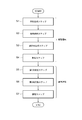
- FIG. 3 is a flowchart showing a method for treating gasified gas according to the first embodiment of the present invention.
- the processing method of the gasified gas according to the first embodiment of the present invention is simply referred to as “the processing method of the first embodiment”.
- the processing method of the first embodiment can be performed using, for example, the processing equipment shown in FIG. Therefore, in the following description, FIGS. 1 and 2 will be referred to as appropriate.
- the treatment method of the first embodiment is a treatment method for gasified gas obtained by gasification of fuel.
- the processing method of the first embodiment includes a steam generation step S1, a steam supply step S2, a condensed water generation step S3, a storage step S4, a first heat exchange step S5, a second heat exchange step S6, a circulation Step S7 is included.
- the steam generation step S1, the steam supply step S2, the condensed water generation step S3, and the storage step S4 are performed during the startup operation of the processing equipment 1.
- the first heat exchange step S5, the second heat exchange step S6, and the circulation step S7 are performed during the normal operation of the processing equipment 1.
- the processing facility 1 (see FIG. 1) is installed, for example, as a part of an integrated coal gasification combined cycle (IGCC). Then, the above-described purification treatment is performed on the gasified gas generated in the gasification furnace (gasification equipment) constituting the IGCC, and a purified gas is obtained.
- the obtained purified gas is supplied to a gas turbine (gasified gas utilization facility) which also constitutes the IGCC, and power generation is performed. Exhaust heat from the gas turbine is recovered by an exhaust heat recovery boiler, and steam is generated. The generated steam is supplied to a steam turbine to generate power.
- the state where power is constantly generated by the gas turbine and the steam turbine corresponds to the normal operation in this specification. Therefore, at the time of normal operation, in the above-mentioned processing equipment 1, purification processing of gasification gas generated in the gasification furnace is performed.
- the IGCC including the processing equipment 1 is started up.
- the start-up operation specifically, first, in each component of the IGCC other than the processing equipment 1 (for example, a gasifier, a gas turbine, a steam turbine, etc .; hereinafter, referred to as a “main engine” (not shown)), a pre-operation preparation (various types) is performed. Start of power supply to the equipment).
- the processing equipment 1 for example, preparations before operation of various equipment (start of circulation of circulating fluid by injecting steam into the circulation system 13, start of power supply to various equipment, and the like) are performed.
- the circulation of the circulating fluid including at least one of steam and condensed water
- the steam turbine is started and the gas turbine is ignited.
- the pressurization of the gasification gas systems 30, 31 and the purified gas system 32 is performed by the supply of pressurized air using a compressor (not shown).
- the gasification furnace included in the main engine is ignited.
- the fuel used at the time of ignition in the gasifier is an auxiliary fuel such as kerosene or light oil at the time of startup.
- a gas having a relatively low temperature for example, about 100 ° C.
- the temperature of the gasified gas systems 30, 31 and the purified gas system 32 rises by flowing the purified gas purification gas through the gasified gas systems 30, 31 and the purified gas system 32.
- the second heat exchanger 12 functions as a heater for heating the gas purification gas. Therefore, when heat is exchanged between the circulation system 13 through which the circulating fluid at the saturation temperature flows, and each of the first heat exchanger 11 and the second heat exchanger 12, the steam supplied to the circulation system 13 Is converted to condensed water in the heat exchanger. The condensed water generated in the first heat exchanger 11 and the second heat exchanger 12 accumulates in the internal space 121A of the second heat exchanger 12 described with reference to FIG. This will be described later with reference to FIG. 4).
- the gas purification gas is heated by the circulating fluid containing steam supplied through the first steam system 14. Therefore, the temperature of the gas purification gas supplied to the gasification gas utilization facility (for example, a gas turbine) through the purification gas system 32 can be quickly raised. As a result, the startup time can be reduced.
- the gasification gas utilization facility for example, a gas turbine
- the steam generation step S1 is a step in which steam is generated by steam generation equipment (not shown) such as an auxiliary boiler.
- the steam supply step S2 is a step of supplying the generated steam to the first heat exchanger 11. Through the steam generation step S1 and the steam supply step S2, the steam generated in the steam generation equipment such as the auxiliary boiler can be supplied to the first heat exchanger 11.
- the condensed water generation step S3 is to generate condensed water at a saturation temperature by exchanging heat with the steam in the first heat exchanger 11.
- the saturation temperature here is synonymous with the saturation temperature described with reference to FIG.
- the storage step S4 is to store the condensed water generated in the condensed water generation step S3 in the internal space 121A of the second heat exchanger 12 (see FIG. 2) up to the reference water level.
- the condensed water generated in the condensed water generation step S3 is introduced into the internal space 121A from the inlet 141 (see FIG. 2) of the housing 121 through the circulation system 13.
- the storage step S4 will be described with reference to FIG.
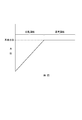
- FIG. 4 is a graph showing a water level change in the second heat exchanger 12 in the storage step S4.
- this graph is a schematic one, and the actual water level does not always match the shape of this graph.
- condensed water having a saturation temperature accumulates in the internal space 121 ⁇ / b> A of the second heat exchanger 12 due to heat exchange with steam in the first heat exchanger 11.
- the condensed water generated in the second heat exchanger 12 since condensed water is also generated in the second heat exchanger 12, the condensed water generated in the second heat exchanger 12 also accumulates in the internal space 121A. Therefore, at the time of the start-up operation, at least the condensed water generated in the first heat exchanger 11 accumulates, and the water level in the internal space 121A (measured by the water level sensor 36) rises.
- the condensed water at the saturation temperature can be accumulated to the reference water level in the internal space 121A of the second heat exchanger 12 during the start-up operation of the gasification gas processing equipment. it can. Thereby, the temperature of the second heat exchanger 12 can be quickly raised to the saturation temperature of the condensed water, and the startup time can be shortened.
- the second heat exchanger 12 functions as a heater for heating the gasified gas.
- the first heat exchange step S5 includes a purification gas obtained by removing at least ammonia and hydrogen chloride (in addition, hydrogen sulfide is also removed in one embodiment of the present invention) from the gasification gas. And heat exchange with the steam at the saturation temperature by the first heat exchanger 11.
- heat exchange is performed by the second heat exchanger 12 between the gasified gas and at least the condensed water generated by the heat exchange in the first heat exchange step S5.
- the circulation step S7 supplies the circulating fluid including at least the condensed water generated in the first heat exchanger 11 to the second heat exchanger 12, and the circulating fluid including at least the steam generated in the second heat exchanger 12. Is supplied to the first heat exchanger 11. The supply of the circulating fluid to the first heat exchanger 11 is performed through the circulation system 13.
- the purified gas can be heated to a higher temperature by heating the purified gas with the saturated temperature steam. Further, the latent heat of the saturated temperature steam is removed by heating the purified gas, and the gasified gas can be cooled by the condensed water having the saturated temperature generated thereby. Therefore, the gasified gas can be cooled to the saturation temperature or higher, and the temperature of the gasification gas can be stably maintained at the saturation temperature or higher. Thereby, the temperature of the gasified gas can be made higher than the precipitation temperature of ammonium chloride by adjusting the steam temperature, and the precipitation of ammonium chloride can be suppressed. Further, since the circulating fluid is circulated by supplying the steam from the second heat exchanger to the first heat exchanger, a new steam supply amount can be reduced.
- the circulation step S7 determines the amount of the circulating fluid (at least one of steam or condensed water) flowing through the circulation system 13 so that the pressure of the circulation system 13 becomes equal to or higher than the reference pressure. Control. Thereby, the pressure of the circulation system 13 can be made higher than the reference pressure, and the saturation temperature of the circulation fluid can be increased.
- FIG. 5 is a system diagram showing a gasified gas treatment facility 1A according to a second embodiment of the present invention.
- the processing facility 1A includes a heating facility 10A, similarly to the processing facility 1 described above.
- the processing equipment 1A includes, in addition to the configuration of the above-described heating equipment 10, a third heat exchanger 51 for generating steam by heat exchange with gasified gas at a stage preceding the second heat exchanger 12.
- a second steam system 62 for supplying steam generated in the third heat exchanger 51 to steam utilization equipment (the first heat exchanger 11 and a steam turbine (not shown)).
- the required value of the temperature of the purified gas supplied to gasified gas utilization equipment such as gas turbines is lower than usual.
- the temperature of the purified gas supplied to the gasified gas utilization facility satisfies the required value, and the heat of the gasified gas becomes excessive. Therefore, the heat of the gasified gas can be used for purposes other than heating the purified gas. Therefore, in such a case, the heat of the gasified gas is recovered in the third heat exchanger 51, and steam is generated by the recovered heat.
- the third heat exchanger 51 includes a so-called kettle-type heat exchanger, similarly to the second heat exchanger 12 (see FIG. 2). Therefore, the third heat exchanger 51 includes a makeup water system 61 for supplying makeup water to an internal space (not shown) of a housing constituting the third heat exchanger 51 and a makeup water system 61 for supplying the makeup water to the third heat exchanger 51.
- a condensed water system 64 for extracting accumulated condensed water is connected.
- Supply of make-up water by the make-up water system 61 is performed by opening the flow control valve 53 provided in the make-up water system 61.
- the supply amount of makeup water is controlled by feedback control based on the flow rate measured by the flow meter 54.
- the extraction of the condensed water by the condensed water system 64 is controlled so that the flow rate measured by the flow meter 56 becomes constant.
- the control of the amount of condensed water withdrawn is performed by controlling the opening degree of the fourth flow control valve 55.
- the third heat exchanger 51 includes a water level sensor 57 for measuring the level of condensed water accumulated in the internal space. Then, during the normal operation of the treatment facility 1A (that is, during the normal operation of the heating facility 10A), when the water level measured by the water level sensor 57 is lower than the reference water level, the water level is set to the reference water level. Supply of makeup water is performed in this manner. When the water level measured by the water level sensor 57 becomes higher than the reference water level, condensed water is extracted through a discharge system (not shown) so that the water level becomes the reference water level.
- the third heat exchanger 51 and the second steam system 62 By providing the third heat exchanger 51 and the second steam system 62, when the purified gas temperature is equal to or higher than the desired temperature and the heat becomes excessive, steam is generated using the heat of the gasified gas. it can. Thereby, the generated steam can be used in the gasification gas processing equipment 1. In particular, by using the generated steam, for example, the amount of extracted air from the steam turbine can be reduced, and the power generation efficiency when power is generated by the steam turbine can be improved.
- the steam utilization equipment to which the steam generated in the third heat exchanger 51 is supplied includes the first heat exchanger 11 in addition to the processing equipment 1. Accordingly, the steam generated in the third heat exchanger 51 is supplied to each facility (not shown) in the plant through the steam extraction system 21, and enters the circulation system 13 through the second steam system 62, and enters the first heat exchanger 11 is supplied. By supplying the steam generated in the third heat exchanger 51 to the first heat exchanger 11, the amount of steam supplied to the first heat exchanger 11 from the outside can be reduced.
- the steam generated in the third heat exchanger 51 is also used for heating the makeup water supplied to the third heat exchanger 51.
- the third steam system 63 is connected, branching from the second steam system 62.
- the third steam system 63 is provided with a water supply heater 52.
- the makeup water is heated by the heat of the steam.
- the steam deprived of heat becomes condensed water as the temperature decreases, and is discharged to the outside. Then, the heated makeup water is supplied to the third heat exchanger 51 through the makeup water system 61, and the water level in the third heat exchanger 51 is recovered.
- the processing equipment 1A having the above configuration can also suppress precipitation of ammonium chloride while sufficiently raising the temperature of the purified gas, similarly to the processing equipment 1 described above.
Landscapes
- Chemical & Material Sciences (AREA)
- Engineering & Computer Science (AREA)
- Combustion & Propulsion (AREA)
- Oil, Petroleum & Natural Gas (AREA)
- Organic Chemistry (AREA)
- Chemical Kinetics & Catalysis (AREA)
- General Chemical & Material Sciences (AREA)
- Inorganic Chemistry (AREA)
- Industrial Gases (AREA)
Abstract
ガス化ガスから少なくともアンモニア及び塩化水素の除去により得られる精製ガスと、飽和温度の蒸気との間で熱交換を行うための第1熱交換器11と、ガス化ガスと、少なくとも、前記熱交換により生成した凝縮水との間で熱交換を行うための第2熱交換器12と、第1熱交換器11と第2熱交換器12との間で、蒸気又は凝縮水のうちの少なくとも一方を含む循環流体を循環させるための循環系統13と、を備え、循環系統13は、第1熱交換器11で生成した凝縮水を少なくとも含む循環流体を第2熱交換器12に供給するように構成されるとともに、第2熱交換器12で生成した蒸気を少なくとも含む循環流体を第1熱交換器11に供給するように構成される。
Description
本開示は、ガス化ガスの処理設備及びガス化ガスの処理方法に関する。
燃料(石炭、重質油等)のガス化により得られたガス化ガスには、一酸化炭素、水素等が含まれる。そのため、ガス化ガスは、例えばガスタービン等のガス化ガス利用設備において利用できる。しかし、燃料のガス化に伴い、ガス化ガスには、例えばアンモニア、塩化水素等の成分が含まれる。そこで、例えば燃料としてガス化ガスを利用する前に、ガス化ガスの精製処理により、アンモニア、塩化水素等の成分を除去することが好ましい。
ガス化ガスの精製処理技術として、特許文献1に記載の技術が知られている。特許文献1には、石炭のガス化により生成したガス化ガスであって、アンモニア及び塩化水素を含むガス化ガスの処理設備が記載されている(例えば段落0019参照)。この処理設備では、ガス化ガスに対し、洗浄等の処理が行われることで、精製ガスが得られる(例えば段落0025、段落0040参照)。得られた精製ガスは、熱交換器においてガス化ガスの熱による加熱後、ガスタービンに供給される(例えば段落0041、0051参照)。
ところで、ガス化ガスの温度は、ガス化設備の運転状態により変動する。ここでいう運転状態は、例えば、燃料の種類及び組成、燃料供給量等を含む。そのため、ガス化ガスの温度が予定していた温度よりも低くなった場合、上記熱交換器での熱交換により得られる熱量が少なくなり、精製ガス温度が予定していた温度よりも低くなる。この結果、精製ガスが例えばガスタービンに供給される場合には、精製ガスの低温化に起因してガスタービンの動作が不安定化する。
また、ガス化ガスの組成も、ガス化設備の運転状態により変動する。例えば、ガス化ガス中のアンモニア濃度及び塩化水素濃度が高い場合、塩化アンモニウムが析出し易くなる。そこで、塩化アンモニウムの析出抑制のために、ガス化ガスは十分な温度に保持されることが好ましい。そのため、ガス化ガスの温度が当該十分な温度になるようにガス化ガスを上記熱交換器において冷却すると、精製ガスへの熱供給量が低下し、精製ガスの温度が低下する。この結果、上記の場合と同様に、例えばガスタービンの動作が不安定化する。
本発明は上記の課題に鑑みて為されたものであり、本発明が解決しようとする課題は、精製ガスを十分に高温化しつつ、塩化アンモニウムの析出を抑制可能なガス化ガスの処理設備及びガス化ガスの処理方法を提供することである。
(1)本発明の少なくとも一実施形態に係るガス化ガスの処理設備は、
燃料のガス化により得られたガス化ガスの処理設備であって、
前記ガス化ガスからアンモニア及び塩化水素の除去により得られる精製ガスと、飽和温度の蒸気との間で熱交換を行うための第1熱交換器と、
前記ガス化ガスと、少なくとも、前記熱交換により生成した凝縮水との間で熱交換を行うための第2熱交換器と、
前記第1熱交換器と前記第2熱交換器との間で、前記蒸気又は前記凝縮水のうちの少なくとも一方を含む循環流体を循環させるための循環系統と、を備え、
前記循環系統は、前記第1熱交換器で生成した前記凝縮水を少なくとも含む前記循環流体を前記第2熱交換器に供給するように構成されるとともに、前記第2熱交換器で生成した蒸気を少なくとも含む前記循環流体を前記第1熱交換器に供給するように構成された
ことを特徴とする。
燃料のガス化により得られたガス化ガスの処理設備であって、
前記ガス化ガスからアンモニア及び塩化水素の除去により得られる精製ガスと、飽和温度の蒸気との間で熱交換を行うための第1熱交換器と、
前記ガス化ガスと、少なくとも、前記熱交換により生成した凝縮水との間で熱交換を行うための第2熱交換器と、
前記第1熱交換器と前記第2熱交換器との間で、前記蒸気又は前記凝縮水のうちの少なくとも一方を含む循環流体を循環させるための循環系統と、を備え、
前記循環系統は、前記第1熱交換器で生成した前記凝縮水を少なくとも含む前記循環流体を前記第2熱交換器に供給するように構成されるとともに、前記第2熱交換器で生成した蒸気を少なくとも含む前記循環流体を前記第1熱交換器に供給するように構成された
ことを特徴とする。
上記(1)の構成によれば、飽和温度の蒸気による精製ガスの加熱により、精製ガスの高温化を図ることができる。また、精製ガスの加熱により飽和温度の蒸気の潜熱が奪われ、これにより生成した飽和温度の凝縮水によりガス化ガスを冷却できる。このため、ガス化ガスを飽和温度以上に冷却でき、ガス化ガスの温度を、安定して飽和温度以上に保持することができる。これにより、蒸気温度の調整によりガス化ガスの温度を塩化アンモニウムの析出温度以上にでき、塩化アンモニウムの析出を抑制できる。さらには、蒸気が第2熱交換器から第1熱交換器に供給されることで循環流体が循環するため、新たな蒸気供給量を削減できる。
(2)幾つかの実施形態では、上記(1)の構成において、
前記循環系統に蒸気を供給するための第1蒸気系統と、
前記循環系統から前記凝縮水を抜き出すための凝縮水系統とを備え、
前記第1蒸気系統は第1流量調整弁を含み、
前記凝縮水系統は第2流量調整弁を含む
ことを特徴とする。
前記循環系統に蒸気を供給するための第1蒸気系統と、
前記循環系統から前記凝縮水を抜き出すための凝縮水系統とを備え、
前記第1蒸気系統は第1流量調整弁を含み、
前記凝縮水系統は第2流量調整弁を含む
ことを特徴とする。
上記(2)の構成によれば、蒸気の供給量と凝縮水の抜き出し量とを調整できる。
(3)幾つかの実施形態では、上記(1)又は(2)の構成において、
前記循環系統から蒸気を抜き出すための蒸気抜き出し系統を備え、
前記蒸気抜き出し系統は第3流量調整弁を含む
ことを特徴とする。
前記循環系統から蒸気を抜き出すための蒸気抜き出し系統を備え、
前記蒸気抜き出し系統は第3流量調整弁を含む
ことを特徴とする。
上記(3)の構成によれば、循環系統の圧力が所望圧力以上になった場合に、循環系統の圧力を所望の圧力に低下できる。また、抜き出した蒸気は、ガス化ガスの処理設備内で利用できる。特に、抜き出した蒸気を利用することで例えば蒸気タービンからの抽気量を低減でき、蒸気タービンにより発電する際の発電効率を向上できる。
(4)幾つかの実施形態では、上記(1)~(3)の何れか1の構成において、
前記第2熱交換器の前段に、前記ガス化ガスとの熱交換により蒸気を生成させるための第3熱交換器と、
前記第3熱交換器において生成した蒸気を蒸気利用設備に供給するための第2蒸気系統と、を備える
ことを特徴とする。
前記第2熱交換器の前段に、前記ガス化ガスとの熱交換により蒸気を生成させるための第3熱交換器と、
前記第3熱交換器において生成した蒸気を蒸気利用設備に供給するための第2蒸気系統と、を備える
ことを特徴とする。
上記(4)の構成によれば、精製ガス温度が所望温度以上であるために熱が余剰になっている場合に、ガス化ガスの熱を利用して蒸気を生成できる。これにより、生成した蒸気をガス化ガスの処理設備内で利用できる。特に、生成した蒸気を利用することで例えば蒸気タービンからの抽気量を低減でき、蒸気タービンにより発電する際の発電効率を向上できる。
(5)幾つかの実施形態では、上記(4)の構成において、
前記蒸気利用設備は、前記第1熱交換器を含む
ことを特徴とする。
前記蒸気利用設備は、前記第1熱交換器を含む
ことを特徴とする。
上記(5)の構成によれば、第1熱交換器への外部からの蒸気供給量を削減できる。
(6)幾つかの実施形態では、上記(1)~(5)の何れか1の構成において、
前記飽和温度は、塩化アンモニウムの析出温度よりも5℃以上高い温度である
ことを特徴とする。
前記飽和温度は、塩化アンモニウムの析出温度よりも5℃以上高い温度である
ことを特徴とする。
上記(6)の構成によれば、より確実に塩化アンモニウムの析出を抑制できる。
(7)本発明の少なくとも一実施形態に係るガス化ガスの処理方法は、
燃料のガス化により得られたガス化ガスの処理方法であって、
前記ガス化ガスからアンモニア及び塩化水素の除去により得られる精製ガスと、飽和温度の蒸気との間で第1熱交換器により熱交換を行う第1熱交換ステップと、
前記ガス化ガスと、少なくとも、前記熱交換により生成した凝縮水との間で第2熱交換器により熱交換を行う第2熱交換ステップと、
前記第1熱交換器で生成した前記凝縮水を少なくとも含む循環流体を前記第2熱交換器に供給するとともに、前記第2熱交換器で生成した蒸気を少なくとも含む前記循環流体を前記第1熱交換器に供給する循環ステップと、を含む
ことを特徴とする。
燃料のガス化により得られたガス化ガスの処理方法であって、
前記ガス化ガスからアンモニア及び塩化水素の除去により得られる精製ガスと、飽和温度の蒸気との間で第1熱交換器により熱交換を行う第1熱交換ステップと、
前記ガス化ガスと、少なくとも、前記熱交換により生成した凝縮水との間で第2熱交換器により熱交換を行う第2熱交換ステップと、
前記第1熱交換器で生成した前記凝縮水を少なくとも含む循環流体を前記第2熱交換器に供給するとともに、前記第2熱交換器で生成した蒸気を少なくとも含む前記循環流体を前記第1熱交換器に供給する循環ステップと、を含む
ことを特徴とする。
上記(7)の構成によれば、飽和温度の蒸気による精製ガスの加熱により、精製ガスの高温化を図ることができる。また、精製ガスの加熱により飽和温度の蒸気の潜熱が奪われ、これにより生成した飽和温度の凝縮水によりガス化ガスを冷却できる。このため、ガス化ガスを飽和温度以上に冷却でき、ガス化ガスの温度を、安定して飽和温度以上に保持することができる。これにより、蒸気温度の調整によりガス化ガスの温度を塩化アンモニウムの析出温度以上にでき、塩化アンモニウムの析出を抑制できる。さらには、蒸気が第2熱交換器から第1熱交換器に供給されることで循環流体が循環するため、新たな蒸気供給量を削減できる。
(8)幾つかの実施形態では、上記(7)の方法において、
前記第2熱交換器は、前記凝縮水を溜めるための内部空間を有する筐体と、前記ガス化ガスが流れる伝熱管であって前記内部空間に露出して配置された伝熱管と、を備え、
前記ガス化ガスの処理方法は、
前記第1熱交換器での蒸気との熱交換により飽和温度の凝縮水を生成させる凝縮水生成ステップと、
前記第2熱交換器の前記内部空間に、前記凝縮水生成ステップで生成した前記凝縮水を基準水位にまで溜める貯留ステップと、を含む
ことを特徴とする。
前記第2熱交換器は、前記凝縮水を溜めるための内部空間を有する筐体と、前記ガス化ガスが流れる伝熱管であって前記内部空間に露出して配置された伝熱管と、を備え、
前記ガス化ガスの処理方法は、
前記第1熱交換器での蒸気との熱交換により飽和温度の凝縮水を生成させる凝縮水生成ステップと、
前記第2熱交換器の前記内部空間に、前記凝縮水生成ステップで生成した前記凝縮水を基準水位にまで溜める貯留ステップと、を含む
ことを特徴とする。
上記(8)の方法によれば、ガス化ガスの処理設備の起動運転時に、飽和温度の凝縮水を第2熱交換器の内部空間での基準水位にまで溜めることができる。これにより、第2熱交換器の温度を凝縮水の飽和温度にまで速やかに昇温でき、起動時間を短くできる。
(9)幾つかの実施形態では、上記(8)の方法において、
蒸気生成設備によって蒸気を生成させる蒸気生成ステップと、
生成した前記蒸気を前記第1熱交換器に供給する蒸気供給ステップとを含む
ことを特徴とする。
蒸気生成設備によって蒸気を生成させる蒸気生成ステップと、
生成した前記蒸気を前記第1熱交換器に供給する蒸気供給ステップとを含む
ことを特徴とする。
上記(9)の方法によれば、蒸気生成設備において生成した蒸気を第1熱交換器に供給できる。
(10)幾つかの実施形態では、上記(7)~(9)の何れか1の方法において、
前記循環ステップは、前記循環系統の圧力が基準圧力以上になるように前記循環系統を流れる前記循環流体の量を制御する
ことを特徴とする。
前記循環ステップは、前記循環系統の圧力が基準圧力以上になるように前記循環系統を流れる前記循環流体の量を制御する
ことを特徴とする。
上記(10)の方法によれば、循環系統の圧力を基準圧力以上にでき、循環流体の飽和温度を高くできる。
本発明の少なくとも一実施形態によれば、精製ガスを十分に高温化しつつ、塩化アンモニウムの析出を抑制可能なガス化ガスの処理設備及びガス化ガスの処理方法を提供できる。
以下、添付図面を参照して本発明の幾つかの実施形態について説明する。ただし、以下に実施形態として記載されている内容又は図面に記載されている内容は、あくまでも例示に過ぎず、本発明の要旨を逸脱しない範囲内で、任意に変更して実施することができる。また、各実施形態は、2つ以上を任意に組み合わせて実施することができる。さらに、各実施形態において、共通する部材については同じ符号を付すものとし、説明の簡略化のために重複する説明は省略する。
また、実施形態として記載されている又は図面に示されている構成部品の寸法、材質、形状、その相対的配置等は、本発明の範囲をこれに限定する趣旨ではなく、単なる説明例にすぎない。
例えば、「ある方向に」、「ある方向に沿って」、「平行」、「直交」、「中心」、「同心」或いは「同軸」等の相対的或いは絶対的な配置を表す表現は、厳密にそのような配置を表すのみならず、公差、若しくは、同じ機能が得られる程度の角度や距離をもって相対的に変位している状態も表すものとする。
例えば、「同一」、「等しい」及び「均質」等の物事が等しい状態であることを表す表現は、厳密に等しい状態を表すのみならず、公差、若しくは、同じ機能が得られる程度の差が存在している状態も表すものとする。
例えば、四角形状や円筒形状等の形状を表す表現は、幾何学的に厳密な意味での四角形状や円筒形状等の形状を表すのみならず、同じ効果が得られる範囲で、凹凸部や面取り部等を含む形状も表すものとする。
一方、一の構成要素を「備える」、「具える」、「具備する」、「含む」、又は、「有する」という表現は、他の構成要素の存在を除外する排他的な表現ではない。
例えば、「ある方向に」、「ある方向に沿って」、「平行」、「直交」、「中心」、「同心」或いは「同軸」等の相対的或いは絶対的な配置を表す表現は、厳密にそのような配置を表すのみならず、公差、若しくは、同じ機能が得られる程度の角度や距離をもって相対的に変位している状態も表すものとする。
例えば、「同一」、「等しい」及び「均質」等の物事が等しい状態であることを表す表現は、厳密に等しい状態を表すのみならず、公差、若しくは、同じ機能が得られる程度の差が存在している状態も表すものとする。
例えば、四角形状や円筒形状等の形状を表す表現は、幾何学的に厳密な意味での四角形状や円筒形状等の形状を表すのみならず、同じ効果が得られる範囲で、凹凸部や面取り部等を含む形状も表すものとする。
一方、一の構成要素を「備える」、「具える」、「具備する」、「含む」、又は、「有する」という表現は、他の構成要素の存在を除外する排他的な表現ではない。
図1は、本発明の第1実施形態に係るガス化ガスの処理設備1を示す系統図である。処理設備1は、石炭、重質油等の燃料のガス化により得られたガス化ガスを処理するためのものである。燃料のガス化は、例えば流動床炉等のガス化設備(図示しない)において行われる。また、ガス化ガスの処理は、ガス化ガス中の硫化カルボニル、アンモニア、塩化水素等の窒素分及び硫黄分の除去により行われる。ガス化ガスの処理により、水素、一酸化炭素等を含む精製ガスが得られる。そして、精製ガスは、例えばガスタービン等のガス化ガス利用設備に供給される。
処理設備1は、ガス化ガスが有する熱を利用して精製ガスを加熱するための加熱設備10と、ガス化ガスの洗浄を行うための洗浄設備3と、硫化水素吸収設備4とを備える。はじめに、ガス化ガスの処理設備1の全体構成についてガス流れを中心に説明し、次いで、処理設備1に備えられる加熱設備10の構成を説明する。
ガス化設備(図示しない)で生成したガス化ガスは、ガス化ガス系統30を通じ、熱交換器2に供給される。熱交換器2は、例えばガス-ガス熱交換器を含んで構成される。ガス化ガスの温度は例えば300℃~500℃程度であり、熱交換器2では、ガス化ガスが有する熱により、精製ガスが例えば250℃~350℃程度にまで加熱される。この加熱により、ガス化ガスの温度は例えば200℃~300℃程度にまで低下する。温度低下後のガス化ガスは、ガス化ガス系統30において、第2熱交換器12(後記する)の前段に備えられたCOS変換器(図示しない)に供給される。COS変換器は変換触媒(図示しない)を備え、変換触媒により、ガス化ガス中の硫化カルボニルが硫化水素に変換される。硫化水素への変換は、例えば、200℃~400℃程度で行うことができる。
生成した硫化水素を含むガス化ガスは、ガス化ガス系統30を通じて、加熱設備10に備えられる第2熱交換器12に供給される。第2熱交換器12では、ガス化ガスと、後記する第1熱交換器11で生成した飽和温度の凝縮水との間で熱交換が行われる。これにより、凝縮水が加熱されて蒸気に相変化するとともに、ガス化ガスが冷却されてガス化ガスの温度が低下する。具体的には、ガス化ガスの温度は、循環系統13の圧力での飽和温度にまで低下する。例えば、循環系統13の圧力が例えば3.0MPaG程度であれば、ガス化ガスの第2熱交換器12の出口温度は、例えば250℃~280℃程度である。従って、この場合、第2熱交換器12は、ガス化ガスを冷却するための冷却器として機能する。
なお、詳細は後記するが、加熱設備10の第1熱交換器11では、ガス化ガスが有する熱と、第1蒸気系統14を通じて供給された蒸気が有する熱とにより、精製ガスが、循環系統13の圧力での飽和温度にまで加熱される。この場合、第1熱交換器11は、精製ガスを加熱するための加熱器として機能する。加熱の際、蒸気の潜熱が奪われることで、蒸気の少なくとも一部が凝縮し、飽和温度の凝縮水が生成する。そして、第1熱交換器11で生成した飽和温度の凝縮水は、上記のように第2熱交換器12に供給される。
第2熱交換器12で熱交換された後のガス化ガスは、ガス化ガス系統30を通じ、洗浄設備3に供給される。洗浄設備3は、例えばスクラバを含んで構成され、洗浄水とガス化ガスとを接触させることで、ガス化ガス中のアンモニア及び塩化水素が除去される。また、ガス化ガス中の硫化水素の一部も、洗浄水に溶解する。なお、除去されたアンモニア及び塩化水素は洗浄水に溶解し、溶解したアンモニア、塩化水素及び硫化水素は処理装置(図示しない)において処理される。
アンモニア等を除去後のガス化ガスは、例えば40℃程度にまで冷却された後、ガス化ガス系統31を通じて、硫化水素吸収設備4に供給される。硫化水素吸収設備4は、例えば塔を含んで構成され、アミン水溶液とガス化ガスとを接触させることで、ガス化ガス中の硫化水素が除去される。
硫化水素除去後のガス化ガスである精製ガスは、精製ガス系統32を通じて、加熱設備10に備えられる第1熱交換器11に供給される。そして、加熱設備10では、精製ガスは、上記のようにガス化ガスが有する熱と、第1蒸気系統14(後記する)を通じて供給された蒸気が有する熱とにより、例えば250℃程度にまで加熱される。加熱後の精製ガスは、精製ガス系統32を通じて熱交換器2に供給され、ガス化ガスの熱により、上記のように例えば250℃~350℃程度にまで加熱される。そして、加熱後の精製ガスは、ガスタービン等のガス利用設備(図示しない)に供給される。
上記の処理設備1において精製ガスを加熱するための加熱設備10は、第1熱交換器11と、第2熱交換器12と、循環系統13とを備える。なお、以下の説明において、加熱設備10に備えられる設備及び系統は、いずれも、処理設備1に備えられる設備及び系統である。
第1熱交換器11は、ガス化ガスから少なくともアンモニア及び塩化水素(これらに加えて、本発明の一実施形態では例えば硫化水素も除去される)の除去により得られる精製ガスと、飽和温度の蒸気との間で熱交換を行うためのものである。具体的には、飽和温度の蒸気により、精製ガスが加熱される。精製ガスの加熱により蒸気の潜熱が奪われることで、蒸気が凝縮し、凝縮水が生成する。なお、ここでいう飽和温度とは、例えば、塩化アンモニウムの析出温度よりも5℃以上高い温度であり、好ましくは10℃以上、より好ましくは20℃以上高い温度である。飽和温度をこのような温度にすることで、より確実に塩化アンモニウムの析出を抑制できる。
また、第2熱交換器12は、ガス化ガスと、少なくとも、上記熱交換により生成した凝縮水との間で熱交換を行うためのものである。具体的には、ガス化ガスの熱により、飽和温度の凝縮水が加熱される。これにより、飽和温度の凝縮水が相変化し、飽和温度の蒸気が生成する。
第1熱交換器11は、例えばガス-ガス熱交換器を含んで構成される。また、第2熱交換器12は、例えば、所謂ケトル型の熱交換器を含んで構成される。第2熱交換器12の構造について、図2を参照しながら説明する。
図2は、上記図1に示す処理設備1に備えられる第2熱交換器12の断面図である。なお、第2熱交換器12の構造は図示の例に限られるものではなく、例えば導入口141の位置を上下反対にする等、その構造は任意に変更できる。
第2熱交換器12は、第1熱交換器11で生成し、循環系統13(後記する)を流れた凝縮水を溜めるための内部空間121Aを有する筐体121と、ガス化ガスが流れる伝熱管122であって内部空間121Aに露出して配置された伝熱管122と、を備える。これらのうち、筐体121は、下面が水平方向に延在するとともに、上面の一部が上方に膨らむような形状を有している。
筐体121の上面には、蒸気を排出するための排出口142と、熱交換させるためのガス化ガスを導入するための導入口146とが備えられる。また、筐体121の下面には、補給水、凝縮水、蒸気を内部空間121Aに導入するための導入口141と、内部空間121Aから排出するための排出口143と、熱交換後のガス化ガスを排出するための排出口145が備えられる。これらのうち、導入口141と排出口142と内部空間121Aを含むことで、循環系統13(図1参照)が構成される。また、排出口143には、凝縮水系統15(図1参照)が接続される。さらに、導入口146と、空間151と、伝熱管122と、空間150と、排出口145とを含むことで、ガス化ガス系統30が構成される。
第2熱交換器12は、内部空間121Aに溜まった凝縮水Lの水位を測定するための水位センサ36を備える。そして、処理設備1の通常運転時(即ち、加熱設備10の通常運転時)には、水位センサ36により測定される水位が基準水位よりも低い場合、水位が基準水位になるように、補給水系統33に備えられた流量調整弁34を開けて補給水の供給が行われる。なお、補給水の供給量制御は、流量計35により測定された流量に基づくフィードバック制御により行われる。なお、水位センサ36により測定される水位が基準水位よりも高くなった場合には、水位が基準水位になるように、図示しない排出系統を通じて凝縮水Lの抜き出しが行われる。
基準水位は、伝熱管122の全体が浸かるような位置に設定される。従って、導入口146を通じて空間151に導入されたガス化ガスは、伝熱管122を流れる際、飽和温度の凝縮水Lとの間で熱交換される。そして、熱交換後のガス化ガスは、空間150及び排出口145を通じて、第2熱交換器12の外部に排出される。
図1に戻り、循環系統13は、第1熱交換器11と第2熱交換器12との間で、蒸気又は凝縮水のうちの少なくとも一方を含む循環流体を循環させるためのものである。即ち、循環系統13は、第1熱交換器11で生成した凝縮水を少なくとも含む循環流体を第2熱交換器12に供給するように構成される。さらには、循環系統13は、第2熱交換器12で生成した蒸気を少なくとも含む循環流体を第1熱交換器11に供給するように構成される。
また、循環系統13を循環する循環流体は、循環系統13の圧力における飽和温度になっている。さらに、循環系統13は、循環系統13への蒸気の供給及び循環系統13から蒸気の排出により、系内の圧力が一定(例えば3.0MPaG程度)になるように構成される。
第1熱交換器11、第2熱交換器12及び循環系統13を備えることで、飽和温度の蒸気による精製ガスの加熱により、精製ガスの高温化を図ることができる。また、精製ガスの加熱により飽和温度の蒸気の潜熱が奪われ、これにより生成した飽和温度の凝縮水によりガス化ガスを冷却できる。このため、ガス化ガスを飽和温度以上に冷却でき、ガス化ガスの温度を、安定して飽和温度以上に保持することができる。これにより、蒸気温度の調整によりガス化ガスの温度を塩化アンモニウムの析出温度以上にでき、塩化アンモニウムの析出を抑制できる。さらには、蒸気が第2熱交換器から第1熱交換器に供給されることで循環流体が循環するため、新たな蒸気供給量を削減できる。
また、加熱設備10は、循環系統13に蒸気を供給するための第1蒸気系統14と、循環系統13からブローダウン水としての凝縮水を抜き出すための凝縮水系統15とを備える。これらのうち、凝縮水系統15は、第2熱交換器12の排出口143(図2参照)に接続される。これにより、循環系統13を流れる凝縮水は、第2熱交換器12及び排出口143を介して、外部に抜き出される。
また、第1蒸気系統14は第1流量調整弁18を含み、凝縮水系統15は第2流量調整弁17を含む。第1流量調整弁18及び第2流量調整弁17を備えることで、蒸気の供給量と凝縮水の抜き出し量とを調整できる。
第1蒸気系統14を通じた循環系統13への蒸気供給は、流量計20により測定される流量が一定になるように制御される。蒸気供給量制御は、第1流量調整弁18の開度制御により行われる。また、循環系統13からの凝縮水抜き出しも、流量計19により測定される流量が一定になるように制御される。凝縮水抜き出し量制御は、第2流量調整弁17の開度制御により行われる。
また、加熱設備10は、循環系統13から蒸気を抜き出すための蒸気抜き出し系統21を備え、蒸気抜き出し系統21は第3流量調整弁22を含む。さらに、加熱設備10は、循環系統13の圧力を測定するための圧力計23を備える。そして、圧力計23により測定される循環系統13の圧力が一定になるように、循環系統13の圧力が一定に制御される。
蒸気抜出し系統21及び第3流量調整弁22を備えることで、循環系統13の圧力が所望圧力以上になった場合に、循環系統13の圧力を所望の圧力に低下できる。また、抜き出した蒸気は、ガス化ガスの処理設備1内で利用できる。特に、抜き出した蒸気を利用することで例えば蒸気タービンからの抽気量を低減でき、蒸気タービンにより発電する際の発電効率を向上できる。なお、循環系統13の圧力が下がった場合には、第1蒸気系統14を通じた蒸気の供給量を増加させる制御が行われる。
加熱設備10を含む処理設備1の制御は、演算制御装置(図示しない)により行われる。演算制御装置は、いずれも図示しないが、CPU(Central Processing Unit)、RAM(Random Access Memory)、ROM(Read Only Memory)、HDD(Hard Disk Drive)、I/F(InterFace)、制御回路等を備え、ROMに格納されている所定の制御プログラムがCPUによって実行されることにより具現化される。
図3は、本発明の第1実施形態に係るガス化ガスの処理方法を示すフローチャートである。以下、本発明の第1実施形態に係るガス化ガスの処理方法を、単に「第1実施形態の処理方法」という。第1実施形態の処理方法は、例えば図1に示す処理設備を用いて行うことができる。そこで、以下の説明においては、適宜、図1及び図2を参照するものとする。
第1実施形態の処理方法は、燃料のガス化により得られたガス化ガスの処理方法である。第1実施形態の処理方法は、蒸気生成ステップS1と、蒸気供給ステップS2と、凝縮水生成ステップS3と、貯留ステップS4と、第1熱交換ステップS5と、第2熱交換ステップS6と、循環ステップS7とを含む。これらのうち、蒸気生成ステップS1と、蒸気供給ステップS2と、凝縮水生成ステップS3と、貯留ステップS4とは、処理設備1の起動運転時に行われる。また、第1熱交換ステップS5と、第2熱交換ステップS6と、循環ステップS7とは、処理設備1の通常運転時に行われる。
ここで、通常運転及び起動運転について説明する。
処理設備1(図1参照)は、例えば、石炭ガス化複合発電(IGCC)の一部として設置される。そして、IGCCを構成するガス化炉(ガス化設備)で生成したガス化ガスについて、上記の精製処理が行われ、精製ガスが得られる。得られた精製ガスは、同じくIGCCを構成するガスタービン(ガス化ガス利用設備)に供給され、発電が行われる。また、ガスタービンでの排熱は排熱回収ボイラで回収され、蒸気が生成する。生成した蒸気は蒸気タービンに供給され、発電が行われる。そして、ガスタービン及び蒸気タービンにより定常的に発電している状態が、本明細書における通常運転に相当する。従って、通常運転時には、上記の処理設備1において、ガス化炉で生成したガス化ガスの精製処理が行われる。
処理設備1(図1参照)は、例えば、石炭ガス化複合発電(IGCC)の一部として設置される。そして、IGCCを構成するガス化炉(ガス化設備)で生成したガス化ガスについて、上記の精製処理が行われ、精製ガスが得られる。得られた精製ガスは、同じくIGCCを構成するガスタービン(ガス化ガス利用設備)に供給され、発電が行われる。また、ガスタービンでの排熱は排熱回収ボイラで回収され、蒸気が生成する。生成した蒸気は蒸気タービンに供給され、発電が行われる。そして、ガスタービン及び蒸気タービンにより定常的に発電している状態が、本明細書における通常運転に相当する。従って、通常運転時には、上記の処理設備1において、ガス化炉で生成したガス化ガスの精製処理が行われる。
一方、例えばメンテナンス等により運転停止していた状態から、通常運転を行うためには、処理設備1を含めたIGCCの起動運転が行われる。起動運転として、具体的にはまず、処理設備1以外のIGCCの各構成設備(例えばガス化炉、ガスタービン、蒸気タービン等。以下「主機」(図示しない)という)において、運転前準備(各種設備への電力供給開始等)が行われる。また、処理設備1では、例えば各種設備の運転前準備(循環系統13への蒸気注入による循環流体の循環開始、各種設備への電力供給開始等)が行われる。これにより、循環系統13では、飽和温度の循環流体(蒸気又は凝縮水のうちの少なくとも一方を含む)の循環が開始する。
次いで、主機において、蒸気タービンが起動されるとともに、ガスタービンへの点火が行われる。一方で、処理設備1では、図示しない圧縮機を用いた加圧空気の供給により、ガス化ガス系統30,31及び精製ガス系統32の加圧が行われる。その後、主機に含まれるガス化炉への点火が行われる。ガス化炉での点火に際して使用される燃料は、起動時には例えば灯油、軽油等の補助燃料である。ガス化炉での補助燃料の燃焼により、比較的低温(例えば100℃程度)のガス精製通ガスが生成する。そして、精製したガス精製通ガスをガス化ガス系統30,31及び精製ガス系統32に流すことで、ガス化ガス系統30,31及び精製ガス系統32の温度が上昇する。
ただし、ガス精製通ガスの温度は、上記のように比較的低温である。従って、この場合では、第2熱交換器12は、ガス精製通ガスを加熱するための加熱器として機能する。そのため、飽和温度の循環流体が流れる循環系統13と、第1熱交換器11及び第2熱交換器12のそれぞれとの間で熱交換が行われると、循環系統13に供給された蒸気はそれぞれの熱交換器において凝縮水に変化する。そして、第1熱交換器11及び第2熱交換器12で生成した凝縮水は、上記の図2を参照しながら説明した第2熱交換器12の内部空間121Aに溜まる(この点の詳細は図4を参照しながら後記する)。
また、第1熱交換器11では、第1蒸気系統14を通じて供給された蒸気を含む循環流体により、ガス精製通ガスが加熱される。そのため、精製ガス系統32を通じてガス化ガス利用設備(例えばガスタービン)に供給されるガス精製通ガス温度を速やかに昇温できる。これにより、起動時間を短縮できる。
第1熱交換器11での加熱によりガス精製通ガスの温度が十分に昇温すると、ガス化炉で燃焼させる燃料が石炭に変更される。これにより、ガス化炉では、石炭の燃焼により、上記のガス精製通ガスの温度よりも高いガス化ガス(例えば上記のように300℃~500℃程度)が生成し始める。生成したガス化ガスは、ガス化ガス系統30,31及び精製ガス系統32を流れ始め、ガス化ガス系統30,31及び精製ガス系統32の温度がさらに上昇する。そして、燃焼させる石炭量を増加させることで負荷を上昇させ、所望の負荷になった時点で起動運転が完了する。起動運転完了後、上記の通常運転が行われる。
蒸気の図3に示す第1実施形態の処理方法において、蒸気生成ステップS1は、例えば補助ボイラ等の蒸気生成設備(図示しない)によって蒸気を生成させるステップである。また、蒸気供給ステップS2は、生成した上記蒸気を第1熱交換器11に供給するステップである。蒸気生成ステップS1及び蒸気供給ステップS2を経ることで、補助ボイラ等の蒸気生成設備において生成した蒸気を第1熱交換器11に供給できる。
凝縮水生成ステップS3は、第1熱交換器11での蒸気との熱交換により飽和温度の凝縮水を生成させるものである。ここでいう飽和温度は、上記の図1を参照しながら説明した飽和温度と同義である。また、貯留ステップS4は、第2熱交換器12の内部空間121A(図2参照)に、凝縮水生成ステップS3で生成した凝縮水を基準水位にまで溜めるものである。凝縮水生成ステップS3で生成した凝縮水は、循環系統13を通じて、筐体121の導入口141(図2参照)から内部空間121Aに導入される。貯留ステップS4について、図4を参照しながら説明する。
図4は、貯留ステップS4における第2熱交換器12での水位変化を示すグラフである。ただし、このグラフは模式的なものであり、実際の水位がこのグラフの形状と必ずしも一致するものではない。
貯留ステップS4では、第1熱交換器11での蒸気との熱交換により飽和温度の凝縮水が、第2熱交換器12の内部空間121Aに溜まる。なお、上記のように、第2熱交換器12においても凝縮水が生成するため、内部空間121Aには、第2熱交換器12で生成した凝縮水も溜まる。そのため、起動運転時には、少なくとも第1熱交換器11で生成した凝縮水が溜まることで、内部空間121Aでの水位(上記の水位センサ36により測定される)は上昇する。
そして、起動運転完了後、通常運転時には、上記のように、一定量の蒸気が循環系統13に供給されるとともに、一定量の凝縮水が内部空間121Aから抜き出される。これにより、内部空間121Aでの水位が基準水位で一定になるようにして、通常運転が行われる。
凝縮水生成ステップS3及び貯留ステップS4を経ることで、ガス化ガスの処理設備の起動運転時に、飽和温度の凝縮水を第2熱交換器12の内部空間121Aでの基準水位にまで溜めることができる。これにより、第2熱交換器12の温度を凝縮水の飽和温度にまで速やかに昇温でき、起動時間を短くできる。なお、起動運転時には、第2熱交換器12は、ガス化ガスを加熱するための加熱器として機能する。
図3に戻って、第1熱交換ステップS5は、ガス化ガスから少なくともアンモニア及び塩化水素(これらに加えて、本発明の一実施形態では硫化水素も除去される)の除去により得られる精製ガスと、飽和温度の蒸気との間で第1熱交換器11により熱交換を行うものである。また、第2熱交換ステップS6は、ガス化ガスと、少なくとも、第1熱交換ステップS5での熱交換により生成した凝縮水との間で第2熱交換器12により熱交換を行うものである。さらに、循環ステップS7は、第1熱交換器11で生成した凝縮水を少なくとも含む循環流体を第2熱交換器12に供給するとともに、第2熱交換器12で生成した蒸気を少なくとも含む循環流体を第1熱交換器11に供給するものである。循環流体の第1熱交換器11への供給は、循環系統13を通じて行われる。
第1熱交換ステップS5、第2熱交換ステップS6及び循環ステップS7を経ることで、飽和温度の蒸気による精製ガスの加熱により、精製ガスの高温化を図ることができる。また、精製ガスの加熱により飽和温度の蒸気の潜熱が奪われ、これにより生成した飽和温度の凝縮水によりガス化ガスを冷却できる。このため、ガス化ガスを飽和温度以上に冷却でき、ガス化ガスの温度を、安定して飽和温度以上に保持することができる。これにより、蒸気温度の調整によりガス化ガスの温度を塩化アンモニウムの析出温度以上にでき、塩化アンモニウムの析出を抑制できる。さらには、蒸気が第2熱交換器から第1熱交換器に供給されることで循環流体が循環するため、新たな蒸気供給量を削減できる。
また、第1実施形態の処理方法では、循環ステップS7は、循環系統13の圧力が基準圧力以上になるように循環系統13を流れる循環流体(蒸気又は凝縮水のうちの少なくとも一方)の量を制御する。これにより、循環系統13の圧力を基準圧力以上にでき、循環流体の飽和温度を高くできる。
図5は、本発明の第2実施形態に係るガス化ガスの処理設備1Aを示す系統図である。処理設備1Aは、上記の処理設備1と同様に、加熱設備10Aを備える。ただし、処理設備1Aは、上記の加熱設備10の構成に加えて、第2熱交換器12の前段に、ガス化ガスとの熱交換により蒸気を生成させるための第3熱交換器51と、第3熱交換器51において生成した蒸気を蒸気利用設備(第1熱交換器11及び蒸気タービン(図示しない))に供給するための第2蒸気系統62と、を備える。
ガスタービン等のガス化ガス利用設備に供給される精製ガス温度の要求値が、通常よりも低い場合がある。この場合、ガス化ガス利用設備に供給される精製ガス温度は要求値を満たすとともに、ガス化ガスが有する熱が余剰になる。そのため、ガス化ガスの熱を、精製ガスの加熱以外に利用できる。そこで、このような場合には、第3熱交換器51においてガス化ガスの熱を回収し、回収された熱により蒸気が生成するようになっている。
第3熱交換器51は、上記の第2熱交換器12と同様に、所謂ケトル型の熱交換器を含んで構成される(図2を参照)。そのため、第3熱交換器51には、第3熱交換器51を構成する筐体の内部空間(図示しない)に補給水を供給するための補給水系統61と、第3熱交換器51に溜まった凝縮水を抜き出すための凝縮水系統64とが接続される。補給水系統61による補給水の供給は、補給水系統61に備えられた流量調整弁53を開けることで行う。補給水の供給量制御は、流量計54により測定された流量に基づくフィードバック制御により行われる。また、凝縮水系統64による凝縮水の抜き出しは、流量計56により測定される流量が一定になるように制御される。凝縮水抜き出し量制御は、第4流量調整弁55の開度制御により行われる。
また、第3熱交換器51は、内部空間に溜まった凝縮水の水位を測定するための水位センサ57を備える。そして、処理設備1Aの通常運転時(即ち、加熱設備10Aの通常運転時)には、水位センサ57により測定される水位が基準水位よりも低い場合、水位が基準水位になるように、上記のようにして補給水の供給が行われる。なお、水位センサ57により測定される水位が基準水位よりも高くなった場合には、水位が基準水位になるように、図示しない排出系統を通じて凝縮水の抜き出しが行われる。
第3熱交換器51及び第2蒸気系統62を備えることで、精製ガス温度が所望温度以上であるために熱が余剰になっている場合に、ガス化ガスの熱を利用して蒸気を生成できる。これにより、生成した蒸気をガス化ガスの処理設備1内で利用できる。特に、生成した蒸気を利用することで例えば蒸気タービンからの抽気量を低減でき、蒸気タービンにより発電する際の発電効率を向上できる。
また、第3熱交換器51で生成した蒸気が供給される蒸気利用設備は、処理設備1のほか、第1熱交換器11を含む。従って、第3熱交換器51で生成した蒸気は、蒸気抜き出し系統21を通じてプラント内各設備(図示しない)に供給されるほか、第2蒸気系統62を通じて循環系統13に入り、第1熱交換器11に供給される。第3熱交換器51で生成した蒸気が第1熱交換器11に供給されることで、第1熱交換器11への外部からの蒸気供給量を削減できる。
さらに、第3熱交換器51で生成した蒸気は、第3熱交換器51に供給される補給水の加熱にも利用される。具体的には、第2蒸気系統62から分岐して、第3蒸気系統63が接続される。第3蒸気系統63には給水ヒータ52が備えられる。給水ヒータ52では、蒸気が有する熱により、補給水が加熱される。一方で、熱を奪われた蒸気は、温度が低下することで凝縮水となり、外部に排出される。そして、加熱された補給水が補給水系統61を通じて第3熱交換器51に供給され、第3熱交換器51での水位の回復が行われる。
以上の構成を有する処理設備1Aによっても、上記の処理設備1と同様に、精製ガスを十分に高温化しつつ、塩化アンモニウムの析出を抑制できる。
1,1A 処理設備
2 熱交換器
3 洗浄設備
4 硫化水素吸収設備
10,10A 加熱設備
11 第1熱交換器
12 第2熱交換器
13 循環系統
14 第1蒸気系統
15,64 凝縮水系統
17 第2流量調整弁
18 第1流量調整弁
19,20,35,54,56 流量計
21 蒸気抜き出し系統
22 第3流量調整弁
23 圧力計
30,31 ガス化ガス系統
32 精製ガス系統
33,61 補給水系統
34,53 流量調整弁
36,57 水位センサ
51 第3熱交換器
52 給水ヒータ
55 第4流量調整弁
62 第2蒸気系統
63 第3蒸気系統
121 筐体
121A 内部空間
122 伝熱管
141,146 導入口
142,143,145 排出口
150,151 空間
L 凝縮水
S1 蒸気生成ステップ
S2 蒸気供給ステップ
S3 凝縮水生成ステップ
S4 貯留ステップ
S5 第1熱交換ステップ
S6 第2熱交換ステップ
S7 循環ステップ
2 熱交換器
3 洗浄設備
4 硫化水素吸収設備
10,10A 加熱設備
11 第1熱交換器
12 第2熱交換器
13 循環系統
14 第1蒸気系統
15,64 凝縮水系統
17 第2流量調整弁
18 第1流量調整弁
19,20,35,54,56 流量計
21 蒸気抜き出し系統
22 第3流量調整弁
23 圧力計
30,31 ガス化ガス系統
32 精製ガス系統
33,61 補給水系統
34,53 流量調整弁
36,57 水位センサ
51 第3熱交換器
52 給水ヒータ
55 第4流量調整弁
62 第2蒸気系統
63 第3蒸気系統
121 筐体
121A 内部空間
122 伝熱管
141,146 導入口
142,143,145 排出口
150,151 空間
L 凝縮水
S1 蒸気生成ステップ
S2 蒸気供給ステップ
S3 凝縮水生成ステップ
S4 貯留ステップ
S5 第1熱交換ステップ
S6 第2熱交換ステップ
S7 循環ステップ
Claims (10)
- 燃料のガス化により得られたガス化ガスの処理設備であって、
前記ガス化ガスから少なくともアンモニア及び塩化水素の除去により得られる精製ガスと、飽和温度の蒸気との間で熱交換を行うための第1熱交換器と、
前記ガス化ガスと、少なくとも、前記熱交換により生成した凝縮水との間で熱交換を行うための第2熱交換器と、
前記第1熱交換器と前記第2熱交換器との間で、前記蒸気又は前記凝縮水のうちの少なくとも一方を含む循環流体を循環させるための循環系統と、を備え、
前記循環系統は、前記第1熱交換器で生成した前記凝縮水を少なくとも含む前記循環流体を前記第2熱交換器に供給するように構成されるとともに、前記第2熱交換器で生成した蒸気を少なくとも含む前記循環流体を前記第1熱交換器に供給するように構成された
ことを特徴とする、ガス化ガスの処理設備。 - 前記循環系統に蒸気を供給するための第1蒸気系統と、
前記循環系統から前記凝縮水を抜き出すための凝縮水系統とを備え、
前記第1蒸気系統は第1流量調整弁を含み、
前記凝縮水系統は第2流量調整弁を含む
ことを特徴とする、請求項1に記載のガス化ガスの処理設備。 - 前記循環系統から蒸気を抜き出すための蒸気抜き出し系統を備え、
前記蒸気抜き出し系統は第3流量調整弁を含む
ことを特徴とする、請求項1又は2に記載のガス化ガスの処理設備。 - 前記第2熱交換器の前段に、前記ガス化ガスとの熱交換により蒸気を生成させるための第3熱交換器と、
前記第3熱交換器において生成した蒸気を蒸気利用設備に供給するための第2蒸気系統と、を備える
ことを特徴とする、請求項1~3の何れか1項に記載のガス化ガスの処理設備。 - 前記蒸気利用設備は、前記第1熱交換器を含む
ことを特徴とする、請求項4に記載のガス化ガスの処理設備。 - 前記飽和温度は、塩化アンモニウムの析出温度よりも5℃以上高い温度である
ことを特徴とする、請求項1~5の何れか1項に記載のガス化ガスの処理設備。 - 燃料のガス化により得られたガス化ガスの処理方法であって、
前記ガス化ガスから少なくともアンモニア及び塩化水素の除去により得られる精製ガスと、飽和温度の蒸気との間で第1熱交換器により熱交換を行う第1熱交換ステップと、
前記ガス化ガスと、少なくとも、前記熱交換により生成した凝縮水との間で第2熱交換器により熱交換を行う第2熱交換ステップと、
前記第1熱交換器で生成した前記凝縮水を少なくとも含む循環流体を前記第2熱交換器に供給するとともに、前記第2熱交換器で生成した蒸気を少なくとも含む前記循環流体を前記第1熱交換器に供給する循環ステップと、を含む
ことを特徴とする、ガス化ガスの処理方法。 - 前記第2熱交換器は、前記凝縮水を溜めるための内部空間を有する筐体と、前記ガス化ガスが流れる伝熱管であって前記内部空間に露出して配置された伝熱管と、を備え、
前記ガス化ガスの処理方法は、
前記第1熱交換器での蒸気との熱交換により飽和温度の凝縮水を生成させる凝縮水生成ステップと、
前記第2熱交換器の前記内部空間に、前記凝縮水生成ステップで生成した前記凝縮水を基準水位にまで溜める貯留ステップと、を含む
ことを特徴とする、請求項7に記載のガス化ガスの処理方法。 - 蒸気生成設備によって蒸気を生成させる蒸気生成ステップと、
生成した前記蒸気を前記第1熱交換器に供給する蒸気供給ステップとを含む
ことを特徴とする、請求項8に記載のガス化ガスの処理方法。 - 前記循環ステップは、前記循環系統の圧力が基準圧力以上になるように前記循環系統を流れる前記循環流体の量を制御する
ことを特徴とする、請求項7~9の何れか1項に記載のガス化ガスの処理方法。
Priority Applications (3)
| Application Number | Priority Date | Filing Date | Title |
|---|---|---|---|
| US15/734,746 US11946005B2 (en) | 2018-07-26 | 2019-07-18 | Gasification gas treatment facility and gasification gas treatment method |
| CN201980041107.1A CN112368358A (zh) | 2018-07-26 | 2019-07-18 | 气化气体的处理设备以及气化气体的处理方法 |
| EP19842313.9A EP3783086A4 (en) | 2018-07-26 | 2019-07-18 | PROCESSING DEVICE FOR GASIFIED GAS AND PROCESSING METHOD FOR GASIFIED GAS |
Applications Claiming Priority (2)
| Application Number | Priority Date | Filing Date | Title |
|---|---|---|---|
| JP2018139965A JP7066563B2 (ja) | 2018-07-26 | 2018-07-26 | ガス化ガスの処理設備及びガス化ガスの処理方法 |
| JP2018-139965 | 2018-07-26 |
Publications (1)
| Publication Number | Publication Date |
|---|---|
| WO2020022169A1 true WO2020022169A1 (ja) | 2020-01-30 |
Family
ID=69180625
Family Applications (1)
| Application Number | Title | Priority Date | Filing Date |
|---|---|---|---|
| PCT/JP2019/028187 Ceased WO2020022169A1 (ja) | 2018-07-26 | 2019-07-18 | ガス化ガスの処理設備及びガス化ガスの処理方法 |
Country Status (5)
| Country | Link |
|---|---|
| US (1) | US11946005B2 (ja) |
| EP (1) | EP3783086A4 (ja) |
| JP (1) | JP7066563B2 (ja) |
| CN (1) | CN112368358A (ja) |
| WO (1) | WO2020022169A1 (ja) |
Families Citing this family (1)
| Publication number | Priority date | Publication date | Assignee | Title |
|---|---|---|---|---|
| EP4646468A2 (en) * | 2023-01-05 | 2025-11-12 | Sungas Renewables, Inc. | Integrated scrubbing operations for processing of syngas from gasification |
Citations (4)
| Publication number | Priority date | Publication date | Assignee | Title |
|---|---|---|---|---|
| JPH11104451A (ja) * | 1997-10-03 | 1999-04-20 | Mitsubishi Heavy Ind Ltd | ガス精製方法及びガス精製装置 |
| JPH11294186A (ja) * | 1998-04-07 | 1999-10-26 | Ishikawajima Harima Heavy Ind Co Ltd | ガス化複合発電設備 |
| JP2010235915A (ja) * | 2009-03-09 | 2010-10-21 | Central Res Inst Of Electric Power Ind | ガス精製設備及び発電システム |
| JP2017129315A (ja) * | 2016-01-21 | 2017-07-27 | パナソニックIpマネジメント株式会社 | 冷凍サイクル装置 |
Family Cites Families (10)
| Publication number | Priority date | Publication date | Assignee | Title |
|---|---|---|---|---|
| US2720259A (en) * | 1950-04-14 | 1955-10-11 | Chicago Bridge & Iron Co | Gas venting of heat exchangers |
| US4205963A (en) * | 1978-04-28 | 1980-06-03 | Texaco Inc. | Process for gas cleaning with reclaimed water and apparatus for water reclamation |
| JP4019202B2 (ja) | 1997-01-27 | 2007-12-12 | バブコック日立株式会社 | 石炭ガス化装置の起動方法 |
| JPH1119468A (ja) | 1997-07-07 | 1999-01-26 | Mitsubishi Heavy Ind Ltd | ガス精製方法 |
| JP2006232904A (ja) | 2005-02-23 | 2006-09-07 | Hitachi Ltd | 石炭ガス化システムのガス精製方法 |
| JP5412171B2 (ja) | 2009-04-30 | 2014-02-12 | 三菱重工業株式会社 | 合成ガスから酸性ガスを分離する方法および装置 |
| KR20110097203A (ko) * | 2010-02-25 | 2011-08-31 | 삼성전자주식회사 | 히트 펌프 시스템 및 그 제어방법 |
| JP5960069B2 (ja) | 2013-01-17 | 2016-08-02 | 三菱日立パワーシステムズ株式会社 | ガス化炉、ガス化複合発電設備及びガス化炉の起動方法 |
| JP6071622B2 (ja) | 2013-02-21 | 2017-02-01 | 三菱重工業株式会社 | Co2及びh2sを含むガスの回収システム及び方法 |
| CN107325847B (zh) * | 2017-08-04 | 2022-10-28 | 浙江大学 | 一种含焦油高温热解气化气的冷却及余热回收方法和装置 |
-
2018
- 2018-07-26 JP JP2018139965A patent/JP7066563B2/ja active Active
-
2019
- 2019-07-18 US US15/734,746 patent/US11946005B2/en active Active
- 2019-07-18 EP EP19842313.9A patent/EP3783086A4/en not_active Withdrawn
- 2019-07-18 WO PCT/JP2019/028187 patent/WO2020022169A1/ja not_active Ceased
- 2019-07-18 CN CN201980041107.1A patent/CN112368358A/zh active Pending
Patent Citations (5)
| Publication number | Priority date | Publication date | Assignee | Title |
|---|---|---|---|---|
| JPH11104451A (ja) * | 1997-10-03 | 1999-04-20 | Mitsubishi Heavy Ind Ltd | ガス精製方法及びガス精製装置 |
| JP3764568B2 (ja) | 1997-10-03 | 2006-04-12 | 三菱重工業株式会社 | ガス精製方法及びガス精製装置 |
| JPH11294186A (ja) * | 1998-04-07 | 1999-10-26 | Ishikawajima Harima Heavy Ind Co Ltd | ガス化複合発電設備 |
| JP2010235915A (ja) * | 2009-03-09 | 2010-10-21 | Central Res Inst Of Electric Power Ind | ガス精製設備及び発電システム |
| JP2017129315A (ja) * | 2016-01-21 | 2017-07-27 | パナソニックIpマネジメント株式会社 | 冷凍サイクル装置 |
Non-Patent Citations (1)
| Title |
|---|
| See also references of EP3783086A4 |
Also Published As
| Publication number | Publication date |
|---|---|
| US11946005B2 (en) | 2024-04-02 |
| JP2020015824A (ja) | 2020-01-30 |
| EP3783086A1 (en) | 2021-02-24 |
| CN112368358A (zh) | 2021-02-12 |
| US20210238491A1 (en) | 2021-08-05 |
| EP3783086A4 (en) | 2021-08-25 |
| JP7066563B2 (ja) | 2022-05-13 |
Similar Documents
| Publication | Publication Date | Title |
|---|---|---|
| CA2731746C (en) | Boiler apparatus | |
| JP5193160B2 (ja) | 二酸化炭素分離回収装置を備えたガス化発電システム | |
| JP5738293B2 (ja) | 低圧蒸気を発生させる構成および方法 | |
| RU2539943C2 (ru) | Способ удаления увлеченного газа в системе генерирования мощности с комбинированным циклом | |
| JP2011020090A (ja) | 二酸化炭素の回収システム及び方法 | |
| US9739478B2 (en) | System and method for heat recovery steam generators | |
| TW202346703A (zh) | 燃氣輪機設備、及其氨的利用方法 | |
| CN102200057A (zh) | 用于冷却燃气涡轮构件的系统和方法 | |
| CN104254673A (zh) | 联合循环发电设备 | |
| US9163827B2 (en) | System and method for using boiler feedwater | |
| TW201307669A (zh) | 供二氧化碳擷取之控制廢熱的系統及方法 | |
| Rao | Evaporative gas turbine (EvGT)/humid air turbine (HAT) cycles | |
| JP5753433B2 (ja) | ガス化発電システム | |
| JP7066563B2 (ja) | ガス化ガスの処理設備及びガス化ガスの処理方法 | |
| KR101644236B1 (ko) | 석탄 가스화 복합발전 시스템 | |
| EP2577000B1 (en) | Feedwater storage and recirculation system and method | |
| JP2018119772A (ja) | 排熱利用発電システム、制御装置、制御方法及び排熱利用発電システムの製造方法 | |
| JP3652743B2 (ja) | ガス化複合発電プラント | |
| JP2018119775A (ja) | 排熱利用発電システム、制御装置及び制御方法 | |
| JP5461299B2 (ja) | ガス化発電プラント | |
| CN223992225U (zh) | 煤电机组灵活性运行的系统配置 | |
| JP7581079B2 (ja) | ボイラの保管装置およびこれを備えたボイラならびにボイラの保管方法 | |
| KR101687912B1 (ko) | 가스화기 통풍장치 | |
| CN119532722A (zh) | 用于二氧化碳捕集的疏水一体化煮沸器、疏水系统 | |
| JP2008075966A (ja) | 貫流式排熱回収ボイラ |
Legal Events
| Date | Code | Title | Description |
|---|---|---|---|
| 121 | Ep: the epo has been informed by wipo that ep was designated in this application |
Ref document number: 19842313 Country of ref document: EP Kind code of ref document: A1 |
|
| ENP | Entry into the national phase |
Ref document number: 2019842313 Country of ref document: EP Effective date: 20201118 |
|
| WWE | Wipo information: entry into national phase |
Ref document number: 19842313 Country of ref document: EP |
|
| NENP | Non-entry into the national phase |
Ref country code: DE |