WO2020022226A1 - カラムハードウェア及び分離カラム並びにそれらの製造方法 - Google Patents
カラムハードウェア及び分離カラム並びにそれらの製造方法 Download PDFInfo
- Publication number
- WO2020022226A1 WO2020022226A1 PCT/JP2019/028532 JP2019028532W WO2020022226A1 WO 2020022226 A1 WO2020022226 A1 WO 2020022226A1 JP 2019028532 W JP2019028532 W JP 2019028532W WO 2020022226 A1 WO2020022226 A1 WO 2020022226A1
- Authority
- WO
- WIPO (PCT)
- Prior art keywords
- film
- column
- hardware
- column hardware
- liquid chromatography
- Prior art date
- Legal status (The legal status is an assumption and is not a legal conclusion. Google has not performed a legal analysis and makes no representation as to the accuracy of the status listed.)
- Ceased
Links
Images


Classifications
-
- B—PERFORMING OPERATIONS; TRANSPORTING
- B01—PHYSICAL OR CHEMICAL PROCESSES OR APPARATUS IN GENERAL
- B01D—SEPARATION
- B01D15/00—Separating processes involving the treatment of liquids with solid sorbents; Apparatus therefor
- B01D15/08—Selective adsorption, e.g. chromatography
- B01D15/10—Selective adsorption, e.g. chromatography characterised by constructional or operational features
- B01D15/22—Selective adsorption, e.g. chromatography characterised by constructional or operational features relating to the construction of the column
-
- G—PHYSICS
- G01—MEASURING; TESTING
- G01N—INVESTIGATING OR ANALYSING MATERIALS BY DETERMINING THEIR CHEMICAL OR PHYSICAL PROPERTIES
- G01N30/00—Investigating or analysing materials by separation into components using adsorption, absorption or similar phenomena or using ion-exchange, e.g. chromatography or field flow fractionation
- G01N30/02—Column chromatography
- G01N30/60—Construction of the column
-
- B—PERFORMING OPERATIONS; TRANSPORTING
- B01—PHYSICAL OR CHEMICAL PROCESSES OR APPARATUS IN GENERAL
- B01D—SEPARATION
- B01D15/00—Separating processes involving the treatment of liquids with solid sorbents; Apparatus therefor
- B01D15/08—Selective adsorption, e.g. chromatography
- B01D15/10—Selective adsorption, e.g. chromatography characterised by constructional or operational features
- B01D15/20—Selective adsorption, e.g. chromatography characterised by constructional or operational features relating to the conditioning of the sorbent material
- B01D15/206—Packing or coating
-
- G—PHYSICS
- G01—MEASURING; TESTING
- G01N—INVESTIGATING OR ANALYSING MATERIALS BY DETERMINING THEIR CHEMICAL OR PHYSICAL PROPERTIES
- G01N30/00—Investigating or analysing materials by separation into components using adsorption, absorption or similar phenomena or using ion-exchange, e.g. chromatography or field flow fractionation
- G01N30/02—Column chromatography
- G01N30/60—Construction of the column
- G01N30/6004—Construction of the column end pieces
- G01N30/6026—Fluid seals
-
- G—PHYSICS
- G01—MEASURING; TESTING
- G01N—INVESTIGATING OR ANALYSING MATERIALS BY DETERMINING THEIR CHEMICAL OR PHYSICAL PROPERTIES
- G01N30/00—Investigating or analysing materials by separation into components using adsorption, absorption or similar phenomena or using ion-exchange, e.g. chromatography or field flow fractionation
- G01N30/02—Column chromatography
- G01N30/60—Construction of the column
- G01N30/6052—Construction of the column body
-
- G—PHYSICS
- G01—MEASURING; TESTING
- G01N—INVESTIGATING OR ANALYSING MATERIALS BY DETERMINING THEIR CHEMICAL OR PHYSICAL PROPERTIES
- G01N30/00—Investigating or analysing materials by separation into components using adsorption, absorption or similar phenomena or using ion-exchange, e.g. chromatography or field flow fractionation
- G01N30/02—Column chromatography
- G01N2030/022—Column chromatography characterised by the kind of separation mechanism
- G01N2030/027—Liquid chromatography
-
- G—PHYSICS
- G01—MEASURING; TESTING
- G01N—INVESTIGATING OR ANALYSING MATERIALS BY DETERMINING THEIR CHEMICAL OR PHYSICAL PROPERTIES
- G01N30/00—Investigating or analysing materials by separation into components using adsorption, absorption or similar phenomena or using ion-exchange, e.g. chromatography or field flow fractionation
- G01N30/02—Column chromatography
- G01N30/04—Preparation or injection of sample to be analysed
- G01N30/06—Preparation
- G01N30/14—Preparation by elimination of some components
- G01N2030/146—Preparation by elimination of some components using membranes
Definitions
- the present invention relates to column hardware and separation columns for liquid chromatography, and more particularly to column hardware and separation columns used for high performance liquid chromatography (HPLC) or ultra high performance liquid chromatography (UHPLC). Relates to their production methods.
- HPLC high performance liquid chromatography
- UHPLC ultra high performance liquid chromatography
- high performance liquid chromatography means liquid chromatography performed under a pressure of up to 40 MPa.
- Ultra High Performance Liquid Chromatography (UHPLC) means liquid chromatography performed under a pressure greater than 40 MPa and up to 130 MPa.
- the “separation column” is an apparatus used in liquid chromatography, and hereinafter, the “separation column” is also simply referred to as a “column”.
- Column hardware is a component other than the packed bed of the separation column, and is a component having a flow path through which the mobile phase containing the sample comes in contact with or comes into contact with, such as a column tube, a frit (filter), and an end union. , A dispersion plate, a filter assembly, and a filter insert assembly.
- the column tube and end union may be connected by cutting grooves on the outside of the end of the column tube and on the inside of the end union, and screwing the column tube and end union.
- the nut and the ferrule are passed through the end of the column tube, and the end union with the groove cut out is screwed together with the ferrule to connect the column tube and the end union that are fixed by the nut and fixed. .
- a column packed with a small packing material in order to speed up the separation, that is, to generate a large number of theoretical plates in a short time to shorten the separation time.
- a small column packing material reduces the gap between the packing materials constituting a flow path through which a mobile phase containing a sample (hereinafter, also simply referred to as “mobile phase”) passes. Need. Therefore, metal such as stainless steel is used for column hardware having a flow path of a mobile phase such as a column tube in which a packing material is put, so as to withstand high pressure.
- the metal column hardware has metal exposure at the liquid contact part with the mobile phase such as the inner wall of the column tube and the surface of the frit, the analysis of the metal column hardware during the analysis by HPLC or UHPLC.
- the solute in the sample may cause nonspecific metal coordination adsorption on the exposed portion of the metal, and the peak shape of the solute may be distorted.
- Patent Document 1 A forming technique has been proposed (Patent Document 1).
- an inorganic oxide typically a metal oxide film such as SiO 2 is formed by chemical vapor deposition on a surface where the device is wetted with a mobile phase during separation, and an organic material having a desired hydrophobicity or hydrophilicity is further formed.
- Patent Document 2 A technique for covalently bonding an organic coating containing a material has been proposed (Patent Document 2).
- the column tube for liquid chromatography is made of polyetheretherketone (PEEK) resin, and the outer surface is coated with a metal species film to prevent the above-mentioned metal coordination adsorption while maintaining high pressure resistance of the column.
- PEEK polyetheretherketone
- Patent Literature 1 a lumen in which a metal oxide film such as SiO 2 is formed on the inner surface of a lumen, a passage, or a cavity of a metal part which is a flow path to which a mobile phase comes into contact
- Metal parts having passages or cavities can reduce non-specific metal coordination adsorption of solutes in the sample compared to the case without a metal oxide film, but the surface of the formed metal oxide film A plurality of hydroxyl groups, such as silanol groups, exposed to the metal interact with the metal dissolved in the mobile phase, and cause metal coordination adsorption of the solute in the sample. For this reason, collapse of the peak shape due to solute coordination adsorption cannot be prevented. Further, a hydroxyl group exposed on the surface of the metal oxide film and a basic solute in a sample or a solute having a base in a molecule may cause non-specific adsorption, and the peak shape of the solute may be lost.
- an inorganic oxide typically a metal oxide film such as SiO 2 is formed on a surface which is a flow path where a mobile phase comes into contact with a liquid and which is wetted by the mobile phase
- a metal microfluidic device in which an organic coating containing a desired hydrophobic or hydrophilic organic material is covalently bonded, nonspecific metal coordination adsorption of a solute in a sample is reduced, and a metal oxide film is formed.
- Patent Document 2 after applying an organic coating to a flow path, there is neither disclosure nor suggestion as to what kind of filler should be filled in the flow path, Some types will have stronger interaction properties than the filler, which may hinder the elution of solutes in the sample from the flow path.
- the organic coating a C8 or C10 aliphatic hydrocarbon chain is mentioned.
- the filler for performing reverse phase chromatography is butylsilylated silica gel
- the organic coating layer is more likely to be present in the sample than the filler.
- the mobile phase optimized for the packing material may not elute the solute in the sample, or the peak shape of the solute in the sample may be distorted, due to the enhanced hydrophobic interaction characteristics with the hydrophobic solute There is.
- Patent Document 2 discloses specific raw materials and materials of the membrane formed on the surface of the flow channel in contact with the mobile phase. Neither the combination of the raw materials nor the specific manufacturing conditions are disclosed or suggested, and it is unclear how the peak shape can be prevented from collapsing or if it can be prevented.
- the present invention provides a method for analyzing by HPLC or UHPLC, while using a metal column hardware column to achieve high pressure resistance, while preventing non-specific metal coordination adsorption of solutes in a sample, and preventing basic solutes from being absorbed.
- An object is to prevent nonspecific adsorption and nonspecific hydrophobic adsorption of a strongly hydrophobic solute.
- Another object is to make the peak shape of the solute good.
- Another object of the present invention is to make it possible to use column hardware packed with a packing material for chromatography without disturbing the elution of solutes in a sample.
- a mobile phase contacting liquid part which contacts a mobile phase of a metal column hardware uses an appropriate material and contains SiO 2 under appropriate manufacturing conditions. A film is formed, and alkylsilation of SiO 2 is performed using an appropriate material.
- a first SiO 2 film is provided in a liquid mobile phase contact part of a column hardware for liquid chromatography, and a silanol group on the surface of the SiO 2 is alkylsilyl on the first film.
- Liquid chromatography column hardware provided with a second membrane that has been formed by chemical conversion.
- the second film is constituted by a film prepared by alkylsilating silanol groups on the SiO 2 surface of the first film.
- the raw material of the first film is made of inorganic polysilazane, tetraalkoxysilane, methyltrialkoxysilane, dimethyldialkoxysilane, trimethylmonoalkoxysilane, ethyltrialkoxysilane, diethyldialkoxysilane, Alkoxysilane, triethylmonoalkoxysilane, propyltrialkoxysilane, dipropyldialkoxysilane, tripropylmonoalkoxysilane, dimethyl cyclic siloxane such as hexamethylcyclotrisiloxane and octamethylcyclotetrasiloxane, diethyl cyclic siloxane, dipropyl Linear polydimethylsiloxane such as cyclic siloxane, hexamethyldisiloxane, octamethyltrisi
- the raw material of the first membrane is perhydropolysilazane, tetramethoxysilane, tetraethoxysilane, tetrapropoxysilane, methyltrimethoxysilane, methyltriethoxysilane, methyltripropoxy.
- Liquid chromatography column hardware characterized by being at least one selected from silane, dimethyldimethoxysilane, dimethyldiethoxysilane, dimethyldipropoxysilane, trimethylmethoxysilane, trimethylethoxysilane, and trimethylpropoxysilane.
- the raw material of the second membrane is at least one selected from alkyl trialkoxy silanes, dialkyl dialkoxy silanes, and trialkyl monoalkoxy silanes.
- the raw material of the second membrane is methyltrimethoxysilane, methyltriethoxysilane, methyltripropoxysilane, dimethyldimethoxysilane, dimethyldiethoxysilane, dimethyldipropoxysilane, Trimethylmethoxysilane, trimethylethoxysilane, trimethylpropoxysilane, ethyltrimethoxysilane, ethyltriethoxysilane, ethyltripropoxysilane, diethyldimethoxysilane, diethyldiethoxysilane, diethyldipropoxysilane, triethylmethoxysilane, triethylethoxysilane, triethyl
- a column hardware for liquid chromatography which is one or more types selected from propoxysilane.
- the second film is constituted by a film prepared by silyl groups on the surface of SiO 2 being methylsilylated. Wear.
- the second film is constituted by a film produced by silanol groups on the surface of SiO 2 being ethylsilylated. Wear.
- the inner diameter of a column tube constituting the column hardware for liquid chromatography is 1.0 mm or more, and the length is 10 m or less.
- the inner diameter of a column tube constituting the column hardware for liquid chromatography is 2.1 mm or more.
- the first membrane is composed of one layer of a first layer composed of one or more kinds of raw materials. Wear.
- the first membrane may include, in a first layer composed of one or more kinds of raw materials, one kind of a different kind from the raw materials constituting the first layer.
- the column hardware for liquid chromatography is characterized in that the second layer composed of the above-mentioned raw materials is constituted by laminating one or more layers.
- the surface of the first film is constituted by the second layer made of dimethyldiethoxysilane as a raw material, Wear.
- the hydrophobic interaction characteristic of the second membrane is less than or equal to the hydrophobic interaction characteristic of the filler filled in the liquid chromatography column hardware.
- Characteristic column hardware for liquid chromatography is less than or equal to the hydrophobic interaction characteristic of the filler filled in the liquid chromatography column hardware.
- a feature in that the in the liquid chromatography column hardware, mobile phase wetted the surface of the SiO 2 film of liquid chromatography column hardware coated with SiO 2 film is alkylsilylating Column hardware for liquid chromatography.
- a first film of SiO 2 is provided in a liquid mobile phase contact portion of the column hardware for liquid chromatography, and a silanol group on the surface of SiO 2 is alkylsilylated on the first film.
- a method for producing column hardware for liquid chromatography comprising providing a second membrane.
- the metal mobile phase contact portion of the column hardware for liquid chromatography is coated with a first film of SiO 2 , and the SiO 2 of the first film is formed.
- a method for producing column hardware for liquid chromatography characterized in that silanol groups on the surface are alkylsilylated to produce the second membrane.
- the raw material of the first membrane may be an inorganic polysilazane, tetraalkoxysilane, methyltrialkoxysilane, dimethyldialkoxysilane, trimethylmonoalkoxysilane, ethyltrialkoxysilane.
- Dimethyl cyclic siloxane diethyl cyclic siloxane such as hexamethylcyclotrisiloxane, octamethylcyclotetrasiloxane, diethyldialkoxysilane, triethylmonoalkoxysilane, propyltrialkoxysilane, dipropyldialkoxysilane, tripropylmonoalkoxysilane, etc.
- the raw material of the second membrane is at least one selected from alkyl trialkoxy silanes, dialkyl dialkoxy silanes, and trialkyl monoalkoxy silanes. This is a method for producing liquid chromatography column hardware.
- the first film is formed by diluting a gas obtained by diluting a raw material of the first film of SiO 2 in a vacuum having a degree of vacuum of ⁇ 0.099 MPa or more.
- Liquid chromatography characterized by being diffused and brought into contact with the mobile phase contact part, introducing oxygen and / or ozone into contact with the mobile phase contact part, and heating at 300 ° C. or more for 90 minutes or more. This is a method of manufacturing column hardware.
- the production of the second membrane is performed by diffusing a gas obtained by diluting a raw material in a vacuum having a degree of vacuum of ⁇ 0.099 MPa or more.
- a method for producing column hardware for liquid chromatography comprising contacting the surface and heating at 300 ° C. or more for 1 hour or more.
- a method for producing a separation column for liquid chromatography which comprises packing a filler into the column hardware for liquid chromatography produced by the method for producing column hardware for liquid chromatography.
- the column hardware to produce a SiO 2 film in the mobile phase wetted parts made of metal, followed by on SiO 2 film, silanol groups alkylsilylating the SiO 2 surface
- A Schematic diagram of column hardware inlet side structure including cone (dispersion space)
- B Schematic diagram of column hardware inlet side structure including dispersion board
- A Schematic showing the mobile phase wetted part of the column hardware inlet side structure including a cone (dispersion space).
- B Schematic view showing the mobile phase wetted part of the column hardware inlet side structure including a dispersion board.
- the present invention provides a liquid chromatography column hardware, in which a metal mobile phase contact portion, which is a portion in contact with a mobile phase containing a sample, is provided with a first film of SiO 2 , Is a column hardware for liquid chromatography provided with a second film in which a silanol group on the surface of SiO 2 is alkylsilylated. Further, there is provided a separation column for liquid chromatography, wherein the column hardware for liquid chromatography is filled with a filler.
- a first film of SiO 2 is prepared by oxidizing and heating the raw material in the liquid mobile phase contact part of the column hardware for liquid chromatography, and the silanol on the surface of SiO 2 is formed on the first film.
- This is a method for producing column hardware for liquid chromatography in which a group is alkylsilylated by heating a raw material to produce a second membrane.
- the present invention also provides a method for producing a separation column for liquid chromatography, which is produced by filling the column hardware for liquid chromatography with a filler.
- Column hardware is a component other than the packed bed of the separation column, and is a component having a flow path through which the mobile phase containing the sample comes in contact with or comes into contact with, such as a column tube, a frit (filter), and an end union. , A dispersing plate, a filter assembly, a filter insert assembly and the like.
- the components that make up the column hardware may all be made of metal, but include those in which some of the components are made of metal and some of the other components are made of synthetic resin or the like and are not made of metal.
- the “mobile phase liquid contact part” refers to a part of a liquid chromatography column hardware in which a mobile phase (eluent) containing a sample comes in contact with the liquid phase during analysis by liquid chromatography.
- the mobile phase wetted part includes the inner surface of the column tube, frit (filter), end union, dispersion plate, filter assembly and filter insert assembly, and the outer surface of the frit (filter) and dispersion plate. .
- Metal mobile phase wetted part is a mobile phase wetted part of a metal part.
- the column hardware has a configuration in which the first film and the second film are stacked on a metal mobile phase liquid contact part, but the first film and the second film are provided on a mobile phase liquid contact part of a non-metal part.
- a configuration in which the second film is stacked may be used, but a configuration in which the second film is not stacked may be used.
- FIG. 1 shows a schematic view of one end of the column hardware 1 in a state where the first film and the second film are not formed.
- the column hardware 1 is further provided with a similar configuration at the other end of the column tube 21.
- FIG. 1A shows a structure of an inlet side portion of a column hardware 11 including a column tube 21, a frit (filter) 22, and an end union 23 and a cone (dispersion space) 231 in an end union flow path 230.
- FIG. 3 is a schematic diagram, in which the same components are used in the structure of the outlet side of the column hardware 11 to configure the column hardware 11.
- FIG. 1 shows a schematic view of one end of the column hardware 1 in a state where the first film and the second film are not formed.
- the column hardware 1 is further provided with a similar configuration at the other end of the column tube 21.
- FIG. 1A shows a structure of an inlet side portion of a column hardware 11 including a column tube 21, a frit (filter) 22, and an end union 23 and
- 1B is a schematic view of the structure of the inlet side portion of the column hardware 12 including the column tube 21, the frit (filter) 22, the end union 23, and the dispersion board 24, and the outlet side of the column hardware 12. The same parts are used in the structure (1) to constitute the column hardware 12.
- FIG. 2A is a schematic diagram showing the mobile phase contact part 3 of the inlet side structure of the column hardware 11 having the cone (dispersion space) 231 shown in FIG. 1A.
- FIG. 2 (B) is a schematic diagram showing the mobile phase contact part 3 of the inlet side structural portion of the column hardware 12 including the dispersion board 24 shown in FIG. 1 (B).
- an equivalent mobile phase liquid contact part is also formed in each of the structural parts on the outlet side.
- FIG. 3 shows a conceptual diagram of the membrane 4 formed on the metal mobile phase contact part 3 of the column hardware 1.
- a first film 41 is provided in the mobile phase contact part 3, and a second film 42 is provided on the first film 41.
- the mobile phase wet part 3 is provided with a first film 41 of SiO 2 that covers the mobile phase wet part 3, and the first film 41 is further formed on the first film 41.
- the second film 42 is formed by coating the surface 411 of the first film 41 on the opposite side to the mobile phase contact portion 3 and formed by silyl silanol groups on the SiO 2 surface. Is provided.
- the first film 41 is laminated on the mobile phase contact part 3 of the column hardware 1
- the second film 42 is laminated on the surface 411 of the first film 41. It has a three-layer structure.
- the first film 41 and the SiO 2 film of SiO 2, although it may of SiO 2 is composed of 100 wt%, in some cases configured to include a SiO 2 and unavoidable impurities and other ingredients.
- the first film 41 and the SiO 2 film are produced by bringing a raw material for producing SiO 2 into contact with the mobile phase contact portion 3 and treating the raw material. This is because a composition other than 2 may be included. Therefore, it can be said that the first film is a first film containing SiO 2 .
- the sample is prevented from coming into contact with the metal mobile phase contact part 3. Can be done.
- the second film 42 is also formed by alkylsilating a silanol group on the surface of SiO 2 that covers the first film 41, so that the silanol group may remain depending on the reaction conditions and the like. .
- the first film 41 and further the second film 42 may or may not be provided in the mobile phase liquid contact portion of the portion made of components other than metal.
- the first film 41 may be composed of one layer of the first layer composed of one kind of raw material, or may be composed of one layer of the first layer composed of two or more kinds of raw material. Further, on the surface of the first layer composed of one or more raw materials, a second layer composed of one or more raw materials different from the raw material constituting the first layer is laminated one or more layers, The first film 41 may be composed of a plurality of layers.
- the uppermost layer to be the surface 411 of the first film 41 is a film formed using dimethyldiethoxysilane as a raw material. With such a configuration, a part of the methyl groups derived from dimethyldiethoxysilane remains on the surface of the first film, so that the amount of silanol groups on the SiO 2 surface on the surface of the first film is reduced. Because.
- the raw material for producing the first film 41 is not particularly limited as long as it can produce a film containing SiO 2 in the mobile phase contacting liquid portion 3 by oxidation and heating, but it is not limited to inorganic polysilazane, tetraalkoxysilane, Methyl trialkoxy silane, dimethyl dialkoxy silane, trimethyl monoalkoxy silane, ethyl trialkoxy silane, diethyl dialkoxy silane, triethyl monoalkoxy silane, propyl trialkoxy silane, dipropyl dialkoxy silane, tripropyl monoalkoxy silane, hexamethyl cyclo Dimethyl cyclic siloxane such as trisiloxane and octamethylcyclotetrasiloxane, diethyl cyclic siloxane, dipropyl cyclic siloxane, hexamethyldisiloxane, octamethyltrisiloxane and decamethyl
- the inorganic polysilazane is not particularly limited, but perhydropolysilazane can be used.
- the tetraalkoxysilane is not particularly limited, but tetramethoxysilane, tetraethoxysilane, and tetrapropoxysilane can be used.
- An ethoxy group has higher reactivity for dealcoholization condensation than a propoxy group
- a methoxy group has higher reactivity for dealcoholization condensation than ethoxy group
- the higher the reactivity for dealcoholization condensation the more easily the ethoxy group is reactive.
- One film 41 can be manufactured, and the thickness can be increased if the manufacturing conditions are the same.
- tetraethoxysilane is preferable to tetrapropoxysilane, and tetramethoxysilane is preferable to tetraethoxysilane.
- tetraethoxysilane in which ethanol is a by-product, is preferred.
- methyltrialkoxysilane methyltrimethoxysilane, methyltriethoxysilane, and methyltripropoxysilane
- An ethoxy group has higher reactivity for dealcoholization condensation than a propoxy group
- a methoxy group has higher reactivity for dealcoholization condensation than ethoxy group
- the higher the reactivity for dealcoholization condensation the more easily the ethoxy group is reactive.
- One film 41 can be manufactured, and if the manufacturing conditions are the same, the thickness can be increased.
- methyltriethoxysilane is preferable to methyltripropoxysilane, and methyltrimethoxysilane is preferable to methyltriethoxysilane. preferable.
- methyltriethoxysilane which is a by-product of dealcoholization condensation, is preferable.
- the dimethyldialkoxysilane is not particularly limited, but dimethyldimethoxysilane, dimethyldiethoxysilane, and dimethyldipropoxysilane can be used.
- An ethoxy group has higher reactivity for dealcoholization condensation than a propoxy group
- a methoxy group has higher reactivity for dealcoholization condensation than ethoxy group
- the higher the reactivity for dealcoholization condensation the more easily the ethoxy group is reactive.
- One film 41 can be manufactured, and if the manufacturing conditions are the same, the thickness can be increased. Therefore, dimethyldiethoxysilane is preferable to dimethyldipropoxysilane, and dimethyldimethoxysilane is preferable to dimethyldiethoxysilane. .
- dimethyldiethoxysilane which is a by-product of ethanol, is preferable.
- the trimethylmonoalkoxysilane is not particularly limited, but trimethylmethoxysilane, trimethylethoxysilane, and trimethylpropoxysilane can be used.
- An ethoxy group has higher reactivity for dealcoholization condensation than a propoxy group
- a methoxy group has higher reactivity for dealcoholization condensation than ethoxy group
- the higher the reactivity for dealcoholization condensation the more easily the ethoxy group is reactive. Since one film 41 can be manufactured and the thickness can be increased under the same manufacturing conditions, trimethylethoxysilane is preferable to trimethylpropoxysilane, and trimethylmethoxysilane is preferable to trimethylethoxysilane.
- trimethylethoxysilane which is a by-product of ethanol, is preferable.
- a film containing SiO 2 as a main component is easily produced by the dealcoholization condensation of a plurality of molecules. Therefore, from this viewpoint, a film mainly composed of SiO 2 can be easily formed in the order of tetraalkoxysilane, methyltrialkoxysilane, and dimethyldialkoxysilane.
- a film mainly composed of SiO 2 can be easily formed in the order of tetraalkoxysilane, methyltrialkoxysilane, and dimethyldialkoxysilane.
- methyltrialkoxysilane and dimethyldialkoxysilane having a plurality of alkoxy groups in the molecule and having a methyl group in the molecule are preferable for the dealcoholization condensation of a plurality of molecules.
- dimethyldiethoxysilane is preferred from the results of Examples 1 to 3 described later.
- the raw material for producing the second film 42 is not particularly limited as long as it can be alkylsilylated by a condensation reaction of the raw material with a silanol group on the SiO 2 surface of the first film 41 by heating.
- alkyl trialkoxy silane, dialkyl dialkoxy silane, and trialkyl monoalkoxy are not particularly limited, but the shorter the alkyl group in the molecule as the raw material, the more sterically hindered the silanol group on the SiO 2 surface of the first film 41.
- Alkyl silylation can be reduced, and the coverage of alkyl silylation increases, so that methyltrialkoxysilane, dimethyldialkoxysilane, and trimethylmonoalkoxysilane are most preferred, and then ethyltrialkoxysilane, diethyldialkoxysilane, and triethylmonoalkoxy. Silanes are preferred.
- methyltrialkoxysilane methyltrimethoxysilane, methyltriethoxysilane, and methyltripropoxysilane
- An ethoxy group has a higher reactivity in the dealcoholation condensation with a silanol group on the SiO 2 surface of the first film than a propoxy group
- a methoxy group has a higher silanol on the SiO 2 surface of the first film than an ethoxy group.
- the higher the reactivity of dealcohol condensation with a group and the higher the reactivity of dealcohol condensation the more easily the second film 42 can be produced, and the higher the coverage of the first film.
- methyl tripropoxy silane requires the most energy for the reaction of dealcoholization condensation, so methyl triethoxy silane is preferred over methyl tripropoxy silane, and methyl trimethoxy silane is preferred over methyl triethoxy silane.
- methyltriethoxysilane which is a by-product of ethanol, is preferable.
- the ethyltrialkoxysilane is not particularly limited, but ethyltrimethoxysilane, ethyltriethoxysilane, and ethyltripropoxysilane can be used.
- An ethoxy group has a higher reactivity in the dealcoholation condensation with a silanol group on the SiO 2 surface of the first film than a propoxy group, and a methoxy group has a higher silanol on the SiO 2 surface of the first film than an ethoxy group.
- the higher the reactivity of dealcohol condensation with a group and the higher the reactivity of dealcohol condensation the more easily the second film 42 can be produced, and the higher the coverage of the first film.
- ethyltripropoxysilane requires the most energy for the reaction, so ethyltriethoxysilane is preferred over ethyltripropoxysilane, and ethyltrimethoxysilane is preferred over ethyltriethoxysilane.
- ethyltriethoxysilane which is a by-product of ethanol, is preferable.
- the dimethyldialkoxysilane is not particularly limited, but dimethyldimethoxysilane, dimethyldiethoxysilane, and dimethyldipropoxysilane can be used.
- An ethoxy group has a higher reactivity in the dealcoholation condensation with a silanol group on the SiO 2 surface of the first film than a propoxy group, and a methoxy group has a higher silanol on the SiO 2 surface of the first film than an ethoxy group.
- the higher the reactivity of the dealcohol condensation with the group and the higher the reactivity of the dealcohol condensation the more easily the second film 42 can be produced, and the higher the coverage of the first film.
- dimethyldiethoxysilane is preferable to dimethyldipropoxysilane, and dimethyldimethoxysilane is preferable to dimethyldiethoxysilane.
- dimethyldiethoxysilane which is a by-product of dealcoholization condensation, is preferable.
- diethyldialkoxysilane diethyldimethoxysilane, diethyldiethoxysilane, and diethyldipropoxysilane
- An ethoxy group has a higher reactivity in the dealcoholation condensation with a silanol group on the SiO 2 surface of the first film than a propoxy group
- a methoxy group has a higher silanol on the SiO 2 surface of the first film than an ethoxy group.
- the higher the reactivity of the dealcohol condensation with the group and the higher the reactivity of the dealcohol condensation the more easily the second film 42 can be produced, and the higher the coverage of the first film.
- diethyldiethoxysilane is preferable to diethyldipropoxysilane, and diethyldimethoxysilane is preferable to diethyldiethoxysilane.
- diethyldiethoxysilane which is a by-product of dealcoholization condensation, is preferable.
- the trimethylmonoalkoxysilane is not particularly limited, but trimethylmethoxysilane, trimethylethoxysilane, and trimethylpropoxysilane can be used.
- An ethoxy group has a higher reactivity in the dealcoholation condensation with a silanol group on the SiO 2 surface of the first film than a propoxy group, and a methoxy group has a higher silanol on the SiO 2 surface of the first film than an ethoxy group.
- the higher the reactivity of the dealcohol condensation with the group and the higher the reactivity of the dealcohol condensation the more easily the second film 42 can be produced, and the higher the coverage of the first film.
- trimethylethoxysilane is preferred over trimethylpropoxysilane, and trimethylmethoxysilane is preferred over trimethylethoxysilane.
- trimethylethoxysilane which is a by-product of dealcoholization condensation, is preferable.
- the triethylmonoalkoxysilane is not particularly limited, but triethylmethoxysilane, triethylethoxysilane, and triethylpropoxysilane can be used.
- An ethoxy group has a higher reactivity in the dealcoholation condensation with a silanol group on the SiO 2 surface of the first film than a propoxy group, and a methoxy group has a higher silanol on the SiO 2 surface of the first film than an ethoxy group.
- the higher the reactivity of the dealcohol condensation with the group and the higher the reactivity of the dealcohol condensation the more easily the second film 42 can be produced, and the higher the coverage of the first film.
- triethylethoxysilane is preferable to triethylpropoxysilane, and triethylmethoxysilane is preferable to triethylethoxysilane.
- triethylethoxysilane which is a by-product of dealcoholization condensation, is preferred.
- dimethyldiethoxysilane is preferable from the results of Example 3 and Example 9 described later.
- the raw material diluted with a solvent may be applied, or the raw material diluted with an inert gas may be diffused. Is also good.
- the surface of the column hardware including the mobile phase wetted part for example, a film may be formed on the outer surface of the column tube or the like.
- the first film is prepared in the air, under an inert atmosphere or in a vacuum when the raw material does not have an alkyl group (methyl group or the like) directly covalently bonded to a Si atom, such as inorganic polysilazane or tetraalkoxysilane.
- the raw material may be applied or diffused to make contact with the mobile phase liquid contact part of the column hardware, and may be oxidized and condensed by oxygen in air only by heating in air.
- the oxidation and the condensation by the supply of oxygen and / or ozone and the heating may be performed in the air, under an inert atmosphere or in a vacuum. In the case of heating in air, it is preferable to perform heating at 250 ° C. or more for 3 hours or more in air since the production of the first film by the condensation reaction can be promoted.
- the first film is made of a material such as methyltrialkoxysilane, dimethyldialkoxysilane, or trimethylmonoalkoxysilane
- a material such as methyltrialkoxysilane, dimethyldialkoxysilane, or trimethylmonoalkoxysilane
- the raw material is applied or diffused in an atmosphere or in a vacuum and brought into contact with the mobile phase in contact with the mobile phase of the column hardware, and supplied with oxygen and / or ozone and heated in air, in an inert atmosphere or in a vacuum. It can be carried out by oxidation and condensation.
- the first film is made of a material such as ethyl trialkoxy silane, diethyl dialkoxy silane, or triethyl monoalkoxy silane
- a material such as ethyl trialkoxy silane, diethyl dialkoxy silane, or triethyl monoalkoxy silane
- the raw material is applied or diffused in an atmosphere or in a vacuum and brought into contact with the mobile phase in contact with the mobile phase of the column hardware, and supplied with oxygen and / or ozone and heated in air, in an inert atmosphere or in a vacuum. It can be carried out by oxidation and condensation.
- the first film is made of propyl trialkoxysilane, dipropyldialkoxysilane, or tripropylmonoalkoxysilane
- the raw material is applied or diffused in an inert atmosphere or in a vacuum and brought into contact with the mobile phase liquid contact part of the column hardware, and supplied with oxygen and / or ozone in air, under an inert atmosphere or in a vacuum. It can be carried out by oxidation and condensation by heating.
- the first film is prepared by diffusing the raw material in a vacuum of ⁇ 0.099 MPa or more and bringing the raw material into contact with the surface of the mobile phase in contact with the mobile phase in a vacuum of ⁇ 0.099 MPa or more. It is preferable to perform oxidation with ozone and heating at 300 ° C. or higher for 90 minutes or longer.
- the first film can be manufactured under the condition that does not include the absolute vacuum, and the first film is oxidized with oxygen and / or ozone and heated at 300 ° C. or more, so that the first film is formed by the condensation reaction. This is because the production of one film can be promoted. Further, by performing oxidation with oxygen and / or ozone and heating at 300 ° C. or more for 90 minutes or more, the influence of the metal in the mobile phase contact portion of the metal column hardware can be reduced.
- the raw material was directly covalently bonded to Si atoms, such as methyltrialkoxysilane, dimethyldialkoxysilane, and trimethylmonoalkoxysilane. If there is a methyl group, the material is diffused in a vacuum at a degree of vacuum of ⁇ 0.099 MPa or more and brought into contact with the surface of the mobile phase liquid contacting part of the column hardware, and oxidation with oxygen and / or ozone and 300 ° C. or more Is carried out for 4 hours or more.
- the first film can be produced from one kind of raw material, but one layer of the first film can be produced from two or more kinds of raw materials. Further, a first layer made of one or more kinds of raw materials, a second layer made of one or more kinds of different kinds of raw materials different from the raw material of the first layer is laminated one or more times to form a first layer.
- a film can be produced.
- the uppermost layer serving as the surface of the first film be manufactured using dimethyldiethoxysilane as a raw material. With such a configuration, the amount of silanol groups on the SiO 2 surface on the surface of the first film is smaller when part of the methyl groups derived from dimethyldiethoxysilane remains on the surface of the first film. Because it becomes.
- the inner diameter of the column tube is The smaller the diameter of the column and the longer the length of the column tube, the more difficult it becomes to diffuse the raw material, so that heating in air for the production of the first film or oxidation and heating in air or vacuum can be performed. You need to increase the time.
- the first tube is oxidized and heated for 90 minutes into a column tube having an inner diameter of 2.1 mm and a length of 5 cm or a column tube having an inner diameter of 2.1 mm and a length of 15 cm.
- oxidation and heating may be performed for 4 hours.
- a frit having a thickness of 1 mm and a hole diameter of 1.9 ⁇ m or less can be used. By oxidizing and heating for 90 minutes, a first film for obtaining desired performance can be formed. Even when the column hardware has an inner diameter of 1.0 mm, if the filler diameter is 1.9 ⁇ m, the column has the same thickness and the same hole diameter as the frit used in the column hardware using the 2.1 mm inner diameter column tube. Frit can be used.
- an end union having the smallest inner diameter flow path that can be internally processed can be used, and the flow path in the end union is oxidized and heated for 90 minutes.
- a first film for obtaining desired performance can be manufactured.
- the end union has a flow path having the same inner diameter and length as the flow path in the end union used in the column hardware using the column pipe having the inner diameter of 2.1 mm. Can be used.
- a column tube having an inner diameter of 2.1 mm and a length of 5 cm and an inner diameter of 2.1 mm and a length of A first film for obtaining the same performance as that obtained by oxidizing and heating for 90 minutes can be produced in the liquid-contacting portion of the column tube having a length of 15 cm.
- Preparation of the second film 42 can be carried out by alkylsilylating including methylsilyl reduction and ethylsilyl the silanol groups of the SiO 2 surface of the first membrane 41 surface portion containing SiO 2.
- a SiO 2 film may be formed on the surface 411 of the first film 41 separately from the first film in order to form the second film.
- a first film layer comprising a separate SiO 2 and was produced by coating a raw material dissolved in a solvent and physical vapor deposition such as heating or the raw material, SiO 2 produced Can be carried out by subjecting the silanol groups on the SiO 2 surface of the surface portion of the film containing the same to alkylsilylation including methylsilylation and ethylsilylation.
- “on the first film” means that the second film 42 is provided directly on the surface 411 of the first film 41 as shown in FIG. Another film is provided between the second films, and a structure in which three or more films are stacked is also included.
- a third film having a composition different from that of SiO 2 is formed on the surface 411 of the first film 41, a film containing SiO 2 is formed on the surface of the third film, and the formed SiO 2 is formed.
- the second film can be formed on the first film by subjecting the silanol groups on the surface of the SiO 2 surface of the film containing 2 to alkylsilylation including methylsilylation and ethylsilylation.
- the raw materials are used as the surface 411 of the first film of the column hardware, the surface of the film containing SiO 2 different from the first film formed on the surface 411 of the first film, Alternatively, in order to contact the surface of the film containing SiO 2 formed on the surface of the third film, the material diluted with an inert gas can be diffused, and the material diluted with a solvent can be used. Can be applied.
- the second film may cover the first film on the mobile phase liquid contact part, but depending on the method for producing the first film and the method for producing the second film, only the liquid on the mobile phase liquid contact part may be used. Instead, it may be formed on the first membrane formed on the surface of the column hardware including the mobile phase contact part.
- the production of the second film is performed by applying or diffusing the raw material in air, in an inert atmosphere or in a vacuum, and contacting the surface of the first film, and heating in an inert atmosphere or in a vacuum.
- the raw material is diffused in a vacuum, brought into contact with the surface of the first film, and heated in a vacuum. According to such a method, the probability that the raw material comes into contact with the surface of the first film is increased, and the production of the second film by the condensation reaction can be promoted.
- the second film is prepared by diffusing the raw material in a vacuum having a degree of vacuum of -0.099 MPa or more and bringing the raw material into contact with the surface of the first film, and forming the material in a vacuum having a degree of vacuum of -0.099 MPa or more. Is preferably performed for 1 hour or more.
- the second film can be produced under the condition that does not include the absolute vacuum, and by heating at 300 ° C. or more, the production of the second film by the condensation reaction can be promoted. This is because the silanol groups on the surface of the first film can also be dehydrated and condensed.
- heating at 300 ° C. or more for 1 hour or more non-specific adsorption of solutes in the sample is reduced, and a column hardware suitable for accurate qualitative and / or quantitative determination of low-concentration solutes in the sample. This is because wear can be made.
- the production of the second film is performed by diffusing the raw material in a vacuum at a degree of vacuum of ⁇ 0.099 MPa or more and bringing the raw material into contact with the surface of the first film. Is more preferably performed for 2 hours or more.
- the second film can be produced under the condition that does not include the absolute vacuum, and by heating at 300 ° C. or more, the production of the second film by the condensation reaction can be promoted. This is because the silanol groups on the surface of the first film can also be dehydrated and condensed.
- heating at 300 ° C. or more for 2 hours or more nonspecific adsorption of solutes in a sample can be prevented, and column hardware more suitable for accurate qualitative and / or quantitative determination of low-concentration solutes can be produced. Because.
- the chromatogram is not shown, but the production conditions of the first film and the second film in Example 3 described later are not shown.
- a column for UHPLC was prepared by changing only the heating temperature from 300 ° C. to 350 ° C., and a chromatogram was collected and evaluated under the same conditions as in FIG. 6 (A). The peak shape was equivalent to that in FIG. 6 (A). , Peak height was obtained.
- a sealing material such as an O-ring is used to maintain the degree of vacuum in the vacuum chamber.
- a resin material of a commercially available general-purpose sealing material having a high heat-resistant temperature there are vulcanized rubbers such as perfluoroelastomer and fluororubber. Since the heat resistance temperature of the resin material is 330 ° C., if the heating temperature at the time of producing the first film or the second film is 300 ° C., the sealing material made of these resin materials can be used. The production of the first film or the second film can be performed a plurality of times without frequent replacement.
- the heating temperature at the time of producing the first film was changed from 300 ° C. to 400 ° C. among the production conditions of the first film and the second film in Example 3 described later.
- the outer surface of the column hardware became discolored before the first membrane was formed on the outer surface of the column hardware, which made the outer surface of the column hardware dirty. In order to improve the appearance, polishing was required.
- the heating temperature at the time of manufacturing the first film or the second film is preferably 300 ° C. or higher, respectively.
- the heating temperature at the time of manufacturing the first film the effect obtained by the heating temperature greatly exceeds 300 °C, and the cost, time, and effort for improving the appearance or the appearance of the outer surface of the column hardware are taken into consideration. , 300 ° C or higher and lower than 400 ° C.
- the heating temperature at the time of producing the first film or the second film is, respectively, the effect obtained by the heating temperature greatly exceeding 300 ° C., and the cost, time, trouble, energy efficiency, etc. required for replacement of the sealing material.
- the frequency of replacement of a commercially available general-purpose sealing material made of a resin material is not so frequent, and the allowable range is 350 ° C or less
- the heat-resistant temperature of a commercially available general-purpose sealing material made of a resin material is 330 ° C or less.
- the temperature is from 300 ° C to 320 ° C.
- a typical packing material for liquid chromatography is a packing material for reversed-phase chromatography, and octadecylsilylated silica gel (ODS-silica gel) is often used as a packing material for reversed-phase chromatography.
- ODS-silica gel octadecylsilylated silica gel
- the main interaction characteristic of the ODS-modified silica gel is a hydrophobic interaction characteristic due to an octadecyl group, and the higher the hydrophobicity of the solute in the sample, the later the column elutes from the column.
- the main interaction property of the second membrane is the hydrophobic interaction property due to the alkyl group, and the alkyl group of the second membrane must be an octadecyl group or an alkyl group shorter than the octadecyl group.
- the main interaction characteristics of the membrane exceed the main interaction characteristics of the filler (ODS-modified silica gel), and in the mobile phase optimized for the filler (ODS-modified silica gel), some of the solutes in the sample It may not elute.
- the shorter the alkyl group of the second membrane the less the effect of changing the hydrophobicity of the column due to the octadecyl group of the filler. From these viewpoints, the alkyl group of the second film is most preferably a methyl group, and then preferably an ethyl group.
- the column hardware packed with these packing materials does not exceed the hydrophobic interaction characteristics due to the functional groups of the packing materials and has little effect of changing the column hydrophobicity.
- the alkyl group of the membrane is suitably a methyl group, and for column hardware packed with a filler other than methylsilylated silica gel, the alkyl group of the second membrane is most preferably a methyl group, and then preferably an ethyl group. .
- the packing material for reversed phase chromatography includes styrene divinylbenzene copolymer, polymethacrylate, polyvinyl alcohol having a modified butyl group, polyvinyl alcohol having a modified octyl group, and polyvinyl alcohol having a modified octadecyl group.
- fillers based on polymers are used.
- the alkyl group of the second membrane is most preferably a methyl group. Ethyl groups are preferred.
- Fillers for liquid chromatography include fillers for hydrophilic interaction chromatography (Hydrophilic Interaction Chromatography, HILIC) and fillers for normal phase chromatography.
- Silica gel dihydroxypropyl-silylated silica gel, aminopropyl-silylated silica gel, etc.
- silica gel modified with an amide group or a carbamoyl group which is a highly hydrophilic filler, is used.
- the main interaction characteristic of a highly hydrophilic packing material is a hydrophilic interaction characteristic. Among the solutes in a sample, the more hydrophilic solutes elute from the column later.
- the alkyl group of the second film is most preferably a methyl group, and then preferably an ethyl group.
- packing materials for liquid chromatography include size exclusion chromatography (Size Exclusion Chromatography (SEC) fillers, ion exchange chromatography fillers, ligand exchange chromatography fillers, ion exclusion chromatography fillers, and the like.
- SEC Size Exclusion Chromatography
- ion exchange chromatography fillers ligand exchange chromatography fillers
- ion exclusion chromatography fillers ion exclusion chromatography fillers
- a packing material is filled in the column hardware for liquid chromatography to constitute a separation column for liquid chromatography.
- a separation column for liquid chromatography can be manufactured by filling a filler into the column hardware for liquid chromatography manufactured by the above-described method for manufacturing column hardware for liquid chromatography.
- the filler is not particularly limited, and can be appropriately selected from those used for liquid chromatography.
- the method for filling the filler is not particularly limited, and a known filling method can be employed.
- a first membrane made of perhydropolysilazane as a raw material is formed in a mobile phase contact part of stainless steel column hardware, and then a second membrane is formed, that is, a first membrane surface.
- a second membrane is formed, that is, a first membrane surface.
- two columns of column hardware were prepared in which a first membrane made of perhydropolysilazane was formed in the mobile phase liquid contact part of a stainless steel column hardware.
- a solution of perhydropolysilazane in isopropyl alcohol (1.0%, w / v) was prepared in a 1000 mL tall beaker, and column hardware made of stainless steel (inner diameter 2.1 mm, length 5 cm, two column tubes, four frits, (4 end unions) were sunk.
- the sonication was performed for 3 minutes, the column hardware was removed and dried at room temperature for 12 hours on a laboratory bench lined with industrial paper wipers.
- the dried column hardware was transferred into an oven stabilized at 250 ° C. and heat-treated at 250 ° C. for 3 hours.
- Preparation of a second film using chemical vapor deposition of the column hardware that has completed preparation of the first film using perhydropolysilazane as a raw material in the mobile phase liquid contact part of the stainless steel column hardware, that is, the first film Methylsilylation of the film surface was performed.
- the column hardware for one column for which the formation of the first film was completed was put in a vacuum chamber, the door of the vacuum chamber was closed, and the vacuum chamber was heated and stabilized at 300 ° C. Further, the degree of vacuum in the vacuum chamber was stabilized at -0.099 MPa.
- a gas obtained by diluting dimethyldiethoxysilane (DMDES) to 0.05% with nitrogen is vacuum-chambered at 200 sccm (sccm: standard @ cc / min, 1 atm, gas flow per minute at 25 ° C.). And reacted for 2 hours.
- DMDES dimethyldiethoxysilane
- a mobile phase (aqueous solution of 5 mM ammonium formate) was sent at a flow rate of 0.4 mL / min using a UHPLC apparatus Nexera (registered trademark) (Shimadzu Corporation).
- the temperature condition was 40 ° C.
- an MS / MS detector (LCMS-8030 @ plus, Shimadzu Corporation) was used. The ionization of the detector was performed in a positive mode, and MRM (Multi ⁇ Resolution ⁇ Monitoring) was used for detection.
- sample I an aqueous solution of sample I: adenosine triphosphate (ATP, 500 ⁇ g / L), adenosine diphosphate (ADP, 500 ⁇ g / L), and adenosine monophosphate (AMP, 500 ⁇ g / L) was used.
- the sample injection volume was 2 ⁇ L.
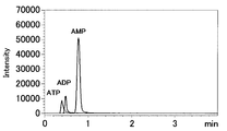
- FIG. 4A shows the chromatogram collected by the column of the example
- FIGS. 4B and 4C show the chromatograms collected by the column of the comparative example.
- FIG. 4 (A) ATP was insufficiently eluted, but ADP and AMP were eluted as peaks, though both were tailed.
- FIG. 4B ATP and ADP were not eluted, and AMP was partially eluted in a form in which the peak shape was lost.
- FIG. 4 (C) ATP and ADP were not eluted, and the peak shape of AMP was more distorted than in FIG. 4 (B), and the elution was insufficient.
- ATP, ADP, and AMP are metal coordinating compounds because they have a phosphate group in each molecule. Since ATP has a triphosphate group, ADP has a diphosphate group, and AMP has a monophosphate group, the metal coordination strength is ATP>ADP> AMP. ATP, ADP, and AMP have a base called adenine in each molecule. ATP, ADP, and AMP have hydrophobicity because each molecule has 10 carbon atoms. In FIG. 4 (C), ATP and ADP, which have strong metal coordination, were not eluted and AMP was insufficiently eluted due to the effect of the metal exposed on the mobile phase liquid contact part of the stainless steel column hardware. You can see that Also, in FIG.
- the mobile phase liquid contact part of the stainless steel column hardware is made of perhydropolysilazane as a raw material and is covered with the first film of SiO 2 .
- AMP eluted with a large area value.
- silanol groups on the surface of the first film of SiO 2 interact with metals dissolved in the mobile phase, causing metal coordination and adsorption of solutes in the sample. , ATP, and ADP were not eluted, and it was found that the peak shape of AMP was largely disturbed.
- the mobile phase contact portion of the stainless steel column hardware is coated with a first film of SiO 2 made of perhydropolysilazane, and the surface of the first film is methylsilylated. It can be seen that the ADP and AMP were eluted as peaks, though both ADP and AMP were tailed because the silanol groups were reduced.
- a first membrane made of methyltriethoxysilane (MTES) as a raw material is formed in a mobile phase contact portion of stainless steel column hardware, and then a second membrane is formed, that is, a first membrane is formed. Methylsilylation of the surface of one film was performed.
- MTES methyltriethoxysilane
- MTES was used as a raw material in the mobile phase contact part of the stainless steel column hardware, and column hardware was prepared for one column using chemical vapor deposition to form the first film.
- stainless steel column hardware (1 column tube, inner diameter 2.1mm, 5cm length, 2 frit, 2 end union) into the vacuum chamber, close the vacuum chamber door, heat the vacuum chamber, Stabilized at 300 ° C. Further, the degree of vacuum in the vacuum chamber was stabilized at -0.099 MPa.
- a gas obtained by diluting MTES to 0.05% with nitrogen was introduced into the vacuum chamber at 200 sccm, and oxygen was introduced into the ozone generator at 2000 sccm, so that the ratio of oxygen to ozone became 98: 2. Gas was introduced into the vacuum chamber and allowed to react for 90 minutes.
- the second hardware using chemical vapor deposition of the column hardware that has completed the first film using MTES as a raw material in the mobile phase contact part of the stainless steel column hardware, that is, the first film was subjected to methylsilylation on the film surface.
- a gas obtained by diluting dimethyldiethoxysilane (DMDES) to 0.05% with nitrogen is introduced into the vacuum chamber at 200 sccm, and the introduction of the mixed gas of oxygen and ozone is stopped. The reaction was performed at a degree of vacuum of -0.099 MPa for 2 hours.
- the column hardware is filled with octadecylsilylated silica gel (Inert SustainSwift @ C18, 1.9 ⁇ m, GL Sciences).
- octadecylsilylated silica gel Inert SustainSwift @ C18, 1.9 ⁇ m, GL Sciences.
- a compound having a metal coordinating base was analyzed under the following conditions, and the peak shape was confirmed (FIG. 5).
- the mobile phase aqueous solution of 5 mM ammonium formate
- the temperature condition was 40 ° C.
- an MS / MS detector LCMS-8030 @ plus, Shimadzu Corporation
- the ionization of the detector was performed in a positive mode, and MRM (Multi ⁇ Resolution ⁇ Monitoring) was used for detection.
- sample I an aqueous solution of sample I: adenosine triphosphate (ATP, 500 ⁇ g / L), adenosine diphosphate (ADP, 500 ⁇ g / L), and adenosine monophosphate (AMP, 500 ⁇ g / L) was used.
- the sample injection volume was 2 ⁇ L.
- FIG. 5 shows the chromatogram collected by the column of the example.
- ATP, ADP, and AMP all eluted as peaks, although tailing occurred.
- the mobile phase liquid contact part of the stainless steel column hardware is covered with a first film made of MTES, and the surface of the first film is methylsilylated and has a reduced amount of silanol groups. It can be seen that ATP, ADP, and AMP all eluted as peaks, though tailing occurred.
- a first membrane made of dimethyldiethoxysilane (DMDES) as a raw material was prepared in a mobile phase contact part of a stainless steel column hardware of a general-purpose UHPLC column, and then a second membrane was prepared, that is, a second membrane was prepared. Methylsilylation of the surface of one film was performed.
- DMDES dimethyldiethoxysilane
- column hardware was prepared using DMDES as a raw material in the mobile phase contact part of a stainless steel column hardware to form a first film using chemical vapor deposition for one column.
- stainless steel column hardware (1 column tube, inner diameter 2.1mm, 5cm length, 2 frit, 2 end union) into the vacuum chamber, close the vacuum chamber door, heat the vacuum chamber, Stabilized at 300 ° C. Further, the degree of vacuum in the vacuum chamber was stabilized at -0.099 MPa.
- a gas obtained by diluting DMDES to 0.05% with nitrogen was introduced into the vacuum chamber at 200 sccm, and oxygen was introduced into the ozone generator at 2000 sccm, whereby the ratio of oxygen to ozone became 98: 2. Gas was introduced into the vacuum chamber and reacted for 90 minutes.
- the column hardware that has completed the production of the first film made of DMDES as a raw material is used.
- the column hardware that has completed the production of the first film made of DMDES as a raw material is used.
- a gas obtained by diluting DMDES to 0.05% with nitrogen was introduced into the vacuum chamber at 200 sccm, and the introduction of the mixed gas of oxygen and ozone was stopped. The reaction was performed at 099 MPa for 2 hours.
- the column hardware that has been subjected to the preparation of the first film and the methylsilation of the surface of the first film (preparation of the second film) is filled with octadecylsilylated silica gel (InertSustainSwift @ C18, 1.9 ⁇ m, GL Sciences), A column having an inner diameter of 2.1 mm and a length of 5 cm was prepared. Using the prepared column, a compound having a metal coordination base was analyzed under the following conditions, and the peak shape was confirmed (FIG. 6 (A)).
- IDEX a column hardware made of polyetheretherketone (PEEK) having a liquid contacting part with a mobile phase was filled with octadecylsilylated silica gel (Inert SustainSwift @ C18, 1.9 ⁇ m, GL Sciences) and had an inner diameter of 2 ⁇ m.
- a compound having a metal-coordinating base having a base was analyzed under the following conditions (FIG. 6 (B)).
- the mobile phase (aqueous solution of 5 mM ammonium formate) was fed at a flow rate of 0.4 mL / min using a UHPLC apparatus Nexera (registered trademark) (Shimadzu Corporation).
- the temperature condition was 40 ° C.
- an MS / MS detector (LCMS-8030 @ plus, Shimadzu Corporation) was used.
- the ionization of the detector was performed in a positive mode, and MRM (Multi ⁇ Resolution ⁇ Monitoring) was used for detection.
- sample I an aqueous solution of sample I: adenosine triphosphate (ATP, 500 ⁇ g / L), adenosine diphosphate (ADP, 500 ⁇ g / L), and adenosine monophosphate (AMP, 500 ⁇ g / L) was used.
- the sample injection volume was 2 ⁇ L.
- FIG. 6A shows a chromatogram collected by the column of the example
- FIG. 6B shows a chromatogram collected by the column of the comparative example.
- ATP, ADP, and AMP all elute as peaks having good symmetry
- the peak height of ADP, AMP is higher than that of FIG. 6B of the comparative example
- the area value is comparative example. 6 (B).
- ATP, ADP, and AMP all eluted as peaks having good symmetry, but the peak height of ADP, AMP was lower than that of FIG. Less than (A).
- the mobile phase contact part of the stainless steel column hardware is coated with a first film made of DMDES, and the surface of the first film is further methylsilylated, so that the silanol groups are extremely reduced. Therefore, ATP, ADP, and AMP all eluted as peaks having good symmetry. Also, since the factor of hydrophobic adsorption is very small, ADP and AMP exceeded the peak area value in the PEEK column, indicating that they were sufficiently eluted. In FIG. 6 (B), since the mobile phase liquid contact part uses column hardware made of PEEK and there is no factor of metal coordination adsorption, ATP, ADP and AMP have good symmetry. It can be seen that it eluted as a peak. Further, since PEEK is a factor of hydrophobic adsorption, it can be seen that the peak area values of ADP and AMP are smaller than those in FIG.
- the peak area value of the compound having a base in the metal coordination in the column using the column hardware of the example was calculated from the collected chromatogram, and the base area was calculated as the base in the metal coordination in the column of PEEK of the comparative example.
- the peak area value of the PEEK column was set to a relative value of 1.00.
- the silanol group becomes less.
- the factor of hydrophobic adsorption is very small as compared with the PEEK column, all of ATP, ADP, and AMP exceeded the peak area value of the PEEK column, indicating that they were sufficiently eluted.
- a first membrane was formed on a mobile phase liquid contact part of a stainless steel column hardware of a general-purpose UHPLC column.
- the first film is formed by forming a first layer made of perhydropolysilazane as a raw material, and then using dimethyldiethoxysilane (DMDES) as a raw material on the surface of the first layer made of perhydropolysilazane.
- DMDES dimethyldiethoxysilane
- a second layer was prepared and laminated in two layers. Subsequently, the second film was produced, that is, methylsilylation of the surface of the first film, specifically, the surface of the second layer using DMDES as a raw material was performed.
- a first layer made of perhydropolysilazane as a raw material was formed in the mobile phase liquid contact part of a stainless steel column hardware, and then a second layer made of DMDES as a raw material was formed.
- a column was prepared by preparing a membrane and then performing a second membrane, that is, methylsilylation on the surface of the first membrane, specifically, methylsilylation on the surface of the second layer using DMDES as a raw material. It was made for this.
- a isopropyl alcohol solution of perhydropolysilazane (1.0%, w / v) was prepared in a 1000 mL tall beaker, and a stainless steel column was used.
- the hardware (1 column tube, 2.1 mm inner diameter, 5 cm length, 2 frits, 2 end unions) was submerged. Sonication was performed for 3 minutes, the column hardware was removed and dried on a laboratory bench with industrial paper wipers for 12 hours at room temperature. The dried column hardware was transferred into an oven stabilized at 250 ° C. and heat-treated at 250 ° C. for 3 hours.
- a column (first layer of the first film) for which perhydropolysilazane is used as a raw material is completed in the mobile phase contact part of the stainless steel column hardware.
- a film made of DMDES as a raw material was produced by using chemical vapor deposition.
- the column hardware for one column for which the production of the membrane using perhydropolysilazane was completed was placed in a vacuum chamber, the door of the vacuum chamber was closed, and the vacuum chamber was heated and stabilized at 300 ° C. Further, the degree of vacuum in the vacuum chamber was stabilized at -0.099 MPa.
- the first layer made of perhydropolysilazane as a raw material and the second layer made of DMDES as a raw material are completed in the mobile phase wetted part of the column hardware made of stainless steel.
- the layer (the second layer of the first film) was subjected to methylsilylation using chemical vapor deposition.
- a gas obtained by diluting DMDES to 0.05% with nitrogen was introduced into the vacuum chamber at 200 sccm, and the introduction of the mixed gas of oxygen and ozone was stopped. The reaction was performed at -0.099 MPa for 2 hours.
- a column was prepared by filling octadecylsilylated silica gel into the column hardware after the preparation of the first film and the methylsilylation of the surface of the first film (preparation of the second film). Specifically, preparation of a first layer using perhydropolysilazane as a raw material, preparation of a second layer using DMDES as a raw material, and formation of a second layer surface using DMDES as a raw material, The methylsilylated column hardware was filled with octadecylsilylated silica gel (Inert SustainSwift @ C18, 1.9 ⁇ m, GL Sciences) to prepare a column having an inner diameter of 2.1 mm and a length of 5 cm.
- octadecylsilylated silica gel Inert SustainSwift @ C18, 1.9 ⁇ m, GL Sciences
- a compound having a metal coordination base was analyzed under the following conditions, and the peak shape was confirmed (FIG. 8).
- the mobile phase aqueous solution of 5 mM ammonium formate
- the temperature condition was 40 ° C.
- an MS / MS detector LCMS-8030 @ plus, Shimadzu Corporation
- the ionization of the detector was performed in a positive mode, and MRM (Multi ⁇ Resolution ⁇ Monitoring) was used for detection.
- sample I an aqueous solution of sample I: adenosine triphosphate (ATP, 500 ⁇ g / L), adenosine diphosphate (ADP, 500 ⁇ g / L), and adenosine monophosphate (AMP, 500 ⁇ g / L) was used.
- the sample injection volume was 2 ⁇ L.
- the collected chromatogram is shown in FIG. In FIG. 8, ATP, ADP, and AMP eluted as peaks having good symmetry.
- the mobile phase wetted part of the stainless steel column hardware is coated with a layer made of perhydropolysilazane as a raw material, and subsequently coated with a layer made of DMDES as a raw material, that is, a first two-layered structure. It can be seen that ATP, ADP, and AMP eluted as peaks with good symmetry because the surface of the layer covered with the film and further using DMDES as a raw material was methylsilylated and the silanol group was very small.
- a first membrane made of dimethyldiethoxysilane (DMDES) is prepared in a mobile phase contact part of a stainless steel column hardware, and then a second membrane is prepared, that is, a second membrane is formed. Methylsilylation of the surface of one film was performed.
- DMDES dimethyldiethoxysilane
- column hardware was prepared using DMDES as a raw material in the mobile phase contact part of a stainless steel column hardware to form a first film using chemical vapor deposition for one column.
- stainless steel column hardware (1 column tube, inner diameter 2.1mm, length 15cm, 2 frit, 2 end union) into the vacuum chamber, close the vacuum chamber door, heat the vacuum chamber, Stabilized at 300 ° C. Further, the degree of vacuum in the vacuum chamber was stabilized at -0.099 MPa.
- a gas obtained by diluting DMDES to 0.05% with nitrogen was introduced into the vacuum chamber at 200 sccm, and oxygen was introduced into the ozone generator at 2000 sccm, whereby the ratio of oxygen to ozone became 98: 2. Gas was introduced into the vacuum chamber and allowed to react for 90 minutes.
- Preparation of the second film using chemical vapor deposition of the column hardware that has completed the preparation of the first film made of DMDES as a raw material in the mobile phase liquid contact part of the stainless steel column hardware, that is, the first film surface was subjected to methylsilylation.
- a gas obtained by diluting DMDES to 0.05% with nitrogen was introduced into the vacuum chamber at 200 sccm, and the introduction of the mixed gas of oxygen and ozone was stopped. The reaction was carried out at 0.099 MPa for 2 hours.
- the column hardware was filled with octadecylsilylated silica gel (Inert SustainSwift @ C18, 3 ⁇ m, GL Sciences Inc.) A column having a length of 0.1 mm and a length of 15 cm was prepared. Using the prepared column, under the following conditions, analysis of a compound having a base in metal coordination and analysis of a compound having a base having strong metal coordination and hydrophobicity were performed, and the peak shape was confirmed ( 9 (A), 10 (A), and 11 (A)).
- untreated stainless steel column hardware was filled with the same octadecylsilylated silica gel as in the example, and a column having an inner diameter of 2.1 mm and a length of 15 cm was prepared.
- a compound having a strong coordination and high hydrophobicity and having a base was analyzed (FIG. 10 (C), FIG. 11 (C)).
- a mobile phase (aqueous solution of 5 mM ammonium formate) was sent at a flow rate of 0.4 mL / min using a UHPLC apparatus Nexera (registered trademark) (Shimadzu Corporation). The temperature condition was 40 ° C.
- an MS / MS detector (LCMS-8030 @ plus, Shimadzu Corporation) was used. The ionization of the detector was performed in a positive mode, and MRM (Multi ⁇ Resolution ⁇ Monitoring) was used for detection.
- an aqueous solution of sample II: adenosine monophosphate (AMP, 500 ⁇ g / L) was used. The sample injection volume was 2 ⁇ L. No measurements were taken on the untreated column hardware.
- the ionization of the detector was performed in a positive mode, and MRM (Multi ⁇ Resolution ⁇ Monitoring) was used for detection.
- MRM Multi ⁇ Resolution ⁇ Monitoring
- the sample injection volume was 3 ⁇ L.
- a phospholipid which is a compound having a metal coordination and high hydrophobicity and having a base
- the mobile phase methanol solution of 5 mM ammonium formate
- the temperature condition was 40 ° C.
- an MS / MS detector LCMS-8030 @ plus, Shimadzu Corporation
- MRM Multi ⁇ Resolution ⁇ Monitoring
- Lysophosphatidic acid (LPA, 0.5 mg / L); 2. phosphatidylinositol (PI, 0.1 mg / L); 3. phosphatidic acid (PA, 0.1 mg / L); 4. phosphatidylserine (PS, 0.1 mg / L); 5. phosphatidylethanolamine (PE, 0.1 mg / L); 6. phosphatidylcholine (PC, 0.05 mg / L); A methanol solution of cardiolipin (CL, 0.5 mg / L) was used. The sample injection volume was 1 ⁇ L.
- FIGS. 9A and 9B The chromatograms collected using Sample II are shown in FIGS. 9A and 9B.
- AMP eluted as a peak having good symmetry.
- FIG. 9B AMP eluted as a peak having good symmetry, but the peak height of AMP was lower than that of FIG. 9A, and the area value was smaller than that of FIG. 9A.
- FIG. 9 (A) the mobile phase contact part of the stainless steel column hardware is covered with a first membrane made of DMDES, and the surface of the first membrane is further methylsilylated, and the amount of silanol groups becomes very small. This indicates that AMP eluted as a peak having good symmetry.
- FIG. 9 (B) AMP was eluted as a peak with good symmetry because the mobile phase contact part uses column hardware made of PEEK and there is no factor for metal coordination adsorption. I understand.
- PEEK is a factor of hydrophobic adsorption, it can be seen that the peak area value of AMP is smaller than that in FIG.
- FIGS. 10A, 10B, and 10C Chromatograms collected using Sample III are shown in FIGS. 10A, 10B, and 10C.
- FIG. 10 (A) FAD is tailed, but eluted at a peak height of 14500, and FMN and Riboflavin eluted as peaks with good symmetry at a peak height of 6500 and 5000, respectively.
- FIG. 10 (B) Riboflavin eluted as a peak equivalent to that of FIG. 10 (A), but FAD tailed more strongly than FIG. 10 (A), and the peak height was 6500.
- the FMN eluted at a peak height of 5500 as a broader peak than in FIG. 10 (A).
- FIG. 10 (C) Riboflavin eluted as a peak equivalent to that of FIG. 10 (A), but FAD and FMN were insufficiently eluted.
- FAD has riboflavin, adenine, and diphosphate in the molecule, it is a compound containing a base, having metal coordination properties, and having high hydrophobicity.
- FMN is a metal coordinating compound because it has riboflavin (Riboflavin) and monophosphate in the molecule, and is a compound whose hydrophobicity is not as high as that of FAD.
- Riboflavin is not a metal coordinating compound because it has no phosphate group in the molecule, and is a compound having the same hydrophobicity as FMN.
- FIG. 10 (A) the mobile phase contact portion of the stainless steel column hardware is covered with a first film made of DMDES, and the surface of the first film is further methylsilylated to reduce silanol groups.
- FAD is eluted at a peak height of 14500, and FMN eluted as a peak with good symmetry, although FAD is tailed because there are few factors that cause a highly hydrophobic compound to adsorb.
- PEEK which is a mobile phase contact part of the column hardware, does not cause a metal coordination compound to be adsorbed, but causes a highly hydrophobic compound to be adsorbed.
- FIGS. 11A, 11B, and 11C The chromatograms collected using the sample IV are shown in FIGS. 11A, 11B, and 11C.
- PS in sample IV is slightly tailed, but all other solutes eluted as peaks with good symmetry.
- FIG. 11B the retention time is generally delayed as compared with FIG. 11A, and solutes other than PC elute with a small area value, but all solutes in the sample IV It eluted as a peak with good symmetry.
- FIG. 11 (C) all the solutes were insufficiently eluted.
- Phospholipids have phosphoric acid in the molecule and have a structure in which fatty acids are ester-bonded, and are therefore highly metal-coordinated and highly hydrophobic compounds.
- PE is a compound having a base called ethanolamine in the molecule
- PC is a compound having a base called choline in the molecule.
- FIG. 11A the mobile phase contact part of the stainless steel column hardware is covered with a first film made of DMDES, and the surface of the first film is further methylsilylated to reduce silanol groups.
- PS is slightly tailed because of the low adsorption of compounds with high hydrophobicity, but all other solutes eluted as peaks with good symmetry.
- PEEK which is a mobile phase contact part of the column hardware, does not cause a metal coordination compound to be adsorbed, but causes a highly hydrophobic compound to be adsorbed.
- the retention time is generally delayed as compared with FIG. 11A, and it can be seen that solutes other than PC elute with a small area value.
- FIG. 11 (C) it can be seen that all the solutes were insufficiently eluted because the metal was exposed in the mobile phase liquid contact part of the untreated column hardware.
- a first membrane made of dimethyldiethoxysilane (DMDES) is prepared in a mobile phase contact part of a stainless steel column hardware, and then a second membrane is prepared, that is, a second membrane is formed. Methylsilylation of the surface of one film was performed. Column hardware was prepared with the time for performing methylsilylation being 1 hour.
- DMDES dimethyldiethoxysilane
- column hardware was prepared using DMDES as a raw material in the mobile phase contact part of a stainless steel column hardware to form a first film using chemical vapor deposition for one column.
- stainless steel column hardware (1 column tube, inner diameter 2.1mm, 5cm length, 2 frit, 2 end union) into the vacuum chamber, close the vacuum chamber door, heat the vacuum chamber, Stabilized at 300 ° C. Further, the degree of vacuum in the vacuum chamber was stabilized at -0.099 MPa.
- a gas obtained by diluting DMDES to 0.05% with nitrogen was introduced into the vacuum chamber at 200 sccm, and oxygen was introduced into the ozone generator at 2000 sccm, whereby the ratio of oxygen to ozone became 98: 2. Gas was introduced into the vacuum chamber and allowed to react for 90 minutes.
- the column hardware that has completed the production of the first film made of DMDES as a raw material is used.
- a gas obtained by diluting DMDES to 0.05% with nitrogen was introduced into the vacuum chamber at 200 sccm, and the introduction of the mixed gas of oxygen and ozone was stopped. The reaction was performed at 099 MPa for 1 hour.
- a metal coordination compound having a base was analyzed under the following conditions.
- the mobile phase aqueous solution of 5 mM ammonium formate
- the temperature condition was 40 ° C.
- an MS / MS detector LCMS-8030 @ plus, Shimadzu Corporation
- the ionization of the detector was performed in a positive mode, and MRM (Multi ⁇ Resolution ⁇ Monitoring) was used for detection.
- sample I an aqueous solution of sample I: adenosine triphosphate (ATP, 500 ⁇ g / L), adenosine diphosphate (ADP, 500 ⁇ g / L), and adenosine monophosphate (AMP, 500 ⁇ g / L) was used.
- the sample injection volume was 2 ⁇ L.
- FIG. 12 shows a chromatogram collected by the column of the example.
- tailing is seen in ATP, but both ADP and AMP eluted as peaks having good symmetry.
- the mobile phase liquid contact part of the stainless steel column hardware is covered with a first film made of DMDES, and the surface of the first film is further methylsilylated and has a reduced amount of silanol groups.
- tailing is seen in ATP, it can be seen that both ADP and AMP eluted as peaks having good symmetry.
- a first membrane made of dimethyldiethoxysilane (DMDES) was prepared in the mobile phase liquid contact part of the stainless steel column hardware, and then a second membrane was prepared, that is, methylsilylation of the first membrane surface was performed. went.
- DMDES dimethyldiethoxysilane
- column hardware was prepared in which DMDES was used as a raw material in the mobile phase liquid contact part of a stainless steel column hardware and a first film was formed using chemical vapor deposition.
- stainless steel column hardware (1 column tube, inner diameter 2.1mm, 5cm length, 2 frit, 2 end union) into the vacuum chamber, close the vacuum chamber door, heat the vacuum chamber, Stabilized at 300 ° C. Further, the degree of vacuum in the vacuum chamber was stabilized at -0.099 MPa.
- a gas obtained by diluting DMDES to 0.05% with nitrogen was introduced into the vacuum chamber at 200 sccm, and oxygen was introduced into the ozone generator at 2000 sccm, whereby the ratio of oxygen to ozone became 98: 2. Gas was introduced into the vacuum chamber and allowed to react for 90 minutes.
- the column hardware that has completed the production of the first film using DMDES as a raw material is methylsilylated on the first film surface using chemical vapor deposition (second reaction).
- second reaction chemical vapor deposition
- Preparation of a film Subsequent to the formation of the first film, a gas obtained by diluting DMDES to 0.05% with nitrogen was introduced into the vacuum chamber at 200 sccm, and the introduction of the mixed gas of oxygen and ozone was stopped. The reaction was carried out at 0.099 MPa for 2 hours.
- column hardware in which a first membrane made of DMDES was formed in the mobile phase liquid contact part of stainless steel column hardware was manufactured as follows. Put stainless steel column hardware (1 column tube, inner diameter 2.1mm, 5cm length, 2 frit, 2 end union) into the vacuum chamber, close the vacuum chamber door, heat the vacuum chamber, Stabilized at 300 ° C. Further, the degree of vacuum in the vacuum chamber was stabilized at -0.099 MPa. Subsequently, a gas obtained by diluting DMDES to 0.05% with nitrogen was introduced into the vacuum chamber at 200 sccm, and oxygen was introduced into the ozone generator at 2000 sccm, whereby the ratio of oxygen to ozone became 98: 2. Gas was introduced into the vacuum chamber and allowed to react for 90 minutes.
- a low-polarity capillary column (InertCap (registered trademark) # 1, 0.68 mm in outer diameter, 0.53 mm in inner diameter, 10 cm in length, in which both ends of the ware were chemically bonded to the inner wall of a capillary tube using 100% dimethylpolysiloxane as a stationary phase, respectively. It was connected to an InertCap # 1 (outer diameter 0.68 mm, inner diameter 0.53 mm, length 30 m, stationary phase film thickness 1 ⁇ m, GL Sciences Inc.).
- F1R.8-5 nut, ferrule, liner
- VICI fused silica adapter
- InertCap 1 (outer diameter 0.68 mm, inner diameter 0.53 mm, length 10 cm, stationary phase film thickness 1 ⁇ m) -column hardware-InertCap 1 (outer diameter 0.68 mm, inner diameter 0.53 mm, length 30 m, (Film thickness: 1 ⁇ m), and the outlet of InertCap 1 (0.68 mm in outer diameter, 0.53 mm in inner diameter, 30 m in length, 1 ⁇ m in stationary phase film thickness) is connected to an FID detector (Frame Ionization Detector, hydrogen flame ionization). (Type detector).
- the mobile phase (helium) was supplied at a pressure of 80 kPa using a gas chromatograph GC-4000 (GL Science). The temperature condition was 130 ° C.
- An FID detector (part of GC-4000, GL Sciences) was used for detection. The temperature of the FID detector was 250 ° C.
- the samples include sample V: 1. n-Undecane, 2. 2. n-Nonanol, 3. Naphthagene; 5. n-Dodecane, 5.1, 7-Heptanediol; n-decylamine, 7. n-Tridecane, 8. 9. Methyl-n-decanoate, 9.2,4,5-Trichlorophenol, 10.
- the sample injection volume was 0.4 ⁇ L
- the temperature of the injection port was 250 ° C.
- the split ratio of the injection port was 1/30.
- FIG. 13A shows a chromatogram collected by the column of the example
- FIG. 13B shows a chromatogram collected by the column of the comparative example.
- the basic compound n-decylamine
- FIG. 13B shows a chromatogram collected by the column of the comparative example.
- the basic compound n-decylamine
- FIG. 13B shows the solutes other than 1,7-Heptanediol, which is a metal coordinating compound
- n-decylamine which is a basic compound, eluted as peaks having good shapes.
- 7-Heptanediol and n-Decylamine did not elute.
- FIG. 13 (A) the mobile phase liquid contact part of the stainless steel column hardware is covered with a first film made of DMDES, and the surface of the first film is further methylsilylated to reduce silanol groups. Therefore, it can be seen that n-decylamine in sample V elutes with some tailing, but all other solutes eluted as peaks with good shape.
- FIG. 13 (B) since the mobile phase contact portion of the stainless steel column hardware is covered only with the first film made of DMDES, the metal distribution is affected by the silanol groups on the surface of the first film. It was found that 1,7-Heptanediol, which is a coordinating compound, did not elute. In addition, it can be seen that n-decylamine, which is a basic compound, was adsorbed to silanol groups on the surface of the first film and was not eluted.
- a first film made of dimethyldiethoxysilane (DMDES) was prepared in a mobile phase liquid contact part of a stainless steel column tube for 4 hours, and then a second film was formed, that is, a first film surface was formed. Methylsilylation was performed for 2 hours.
- a first film made of DMDES was prepared in the mobile phase contact portion of a stainless steel column tube for 90 minutes, and then a second film was formed, that is, methylsilation of the first film surface was performed for 2 minutes. Time went.
- a column tube in which DMDES was used as a raw material and a first film was formed using chemical vapor deposition in the mobile phase contact part of a stainless steel column tube was manufactured.
- a stainless steel column tube (outer diameter 1/16 inch, inner diameter 1.0 mm, length 10 m, GL Sciences Inc.) is placed in the vacuum chamber, the door of the vacuum chamber is closed, the vacuum chamber is heated and stabilized at 300 ° C. Was. Further, the degree of vacuum in the vacuum chamber was stabilized at -0.099 MPa.
- the second film using chemical vapor deposition of the column tube which has completed the first film using DMDES as a raw material in the mobile phase contact part of the stainless steel column tube, that is, the first film surface For 2 hours.
- a gas obtained by diluting DMDES to 0.05% with nitrogen was introduced into the vacuum chamber at 200 sccm, and the introduction of the mixed gas of oxygen and ozone was stopped. The reaction was carried out at 0.099 MPa for 2 hours.
- a column tube was prepared using DMDES as a raw material in a mobile phase contact part of a stainless steel column tube to form a first film using chemical vapor deposition.
- a stainless steel column tube (outer diameter 1/16 inch, inner diameter 1.0 mm, length 10 m, GL Sciences Inc.) is placed in the vacuum chamber, the door of the vacuum chamber is closed, the vacuum chamber is heated and stabilized at 300 ° C. Was. Further, the degree of vacuum in the vacuum chamber was stabilized at -0.099 MPa.
- the second film using chemical vapor deposition of the column tube which has completed the first film using DMDES as a raw material in the mobile phase contact part of the stainless steel column tube, that is, the first film surface For 2 hours.
- a gas obtained by diluting DMDES to 0.05% with nitrogen was introduced into the vacuum chamber at 200 sccm, and the introduction of the mixed gas of oxygen and ozone was stopped. The reaction was carried out at 0.099 MPa for 2 hours.
- a low-polarity capillary column (InertCap # 5, outer diameter 0.68 mm, inner diameter 0.53 mm, length 10 cm, stationary phase film thickness 5 ⁇ m, GL Sciences Inc.) chemically bonded to InertCap # 5 (outer diameter 0.68 mm, inner diameter 0. 53 mm, length 30 m, stationary phase film thickness 5 ⁇ m, GL Sciences Inc.).
- a removable fused silica adapter (FS1R.8-5 (nut, ferrule, liner), VICI) for 1/16 inch outer diameter, tighten the nut through a capillary column inside the liner inside the ferrule,
- One end of a stainless steel union for inch (U-322, VICI) was connected to a capillary column.
- the other end of the stainless steel union for 1/16 inch and the column tube on which the first film and the second film were formed were connected to LZN1-10 (long nut 19 mm, VICI) and ZF1S6-10 (ferrule). (VICI).
- a 1/16 inch stainless steel union was prepared by reacting the mobile phase wetted part with DMDES as a raw material for 90 minutes in the same manner as described in Example 7 to produce a first film. The reaction was carried out for 2 hours to perform methylsilylation on the surface of the first film (preparation of the second film).
- InertCap # 5 (outer diameter 0.68 mm, inner diameter 0.53 mm, length 10 cm, stationary phase thickness 5 ⁇ m)-union-column tube where the first membrane and second membrane were prepared-union-InertCap # 5 ( InertCap 5 (outer diameter 0.68 mm, inner diameter 0.53 mm, length 30 m, fixed phase film thickness 5 ⁇ m), connecting as follows: outer diameter 0.68 mm, inner diameter 0.53 mm, length 30 m, stationary phase film thickness 5 ⁇ m) ) Was connected to the inlet of a FID detector (Frame Ionization Detector, flame ionization detector).
- FID detector Fluor
- the first membrane was prepared for 4 hours under the following conditions, and both ends of the column tube, which had been methylsilylated for 2 hours, were connected to gas chromatography columns to analyze metal coordinating compounds and basic compounds. The peak shape was confirmed (FIG. 14A).
- the first film was prepared for 90 minutes, and both ends of the column tube after 2 hours of methylsilylation were connected to a column for gas chromatography, and a metal coordination compound and a basic compound were analyzed. The peak shape was confirmed (FIG. 14 (B)).
- the mobile phase (helium) was supplied at a pressure of 30 kPa using a gas chromatograph GC-4000 (GL Science). The temperature condition was 150 ° C.
- An FID detector (part of GC-4000, GL Sciences) was used for detection. The temperature of the FID detector was 260 ° C.
- the samples include sample V: 1. n-Undecane, 2. 2. n-Nonanol, 3. Naphthagene; 5. n-Dodecane, 5.1, 7-Heptanediol; n-decylamine, 7. n-Tridecane, 8. 9. Methyl-n-decanoate, 9.2,4,5-Trichlorophenol, 10.
- An isopropyl alcohol solution (capillary column test sample D, GL Sciences) containing 0.1% to 0.5% of each of n-Tetradecane was used.
- the sample injection volume was 0.2 ⁇ L
- the temperature of the injection port was 250 ° C.
- the split ratio of the injection port was 1/30.
- FIGS. 14 (A) and 14 (B) The collected chromatograms are shown in FIGS. 14 (A) and 14 (B).
- FIG. 14A using a column tube in which the production of the first film was performed for 4 hours and the methylsilylation of the surface of the first film (production of the second film) was performed for 2 hours, all the samples in sample V were used. The solute eluted as a well-shaped peak.
- FIG. 14B using a column tube in which the first film was formed for 90 minutes and the surface of the first film was subjected to methylsilylation (preparation of the second film) for 2 hours, in particular, in FIG. 1,7-Heptanediol, which is a sex compound, was not partially eluted.
- FIG. 14 (A) the mobile contact portion of a stainless steel column tube having an outer diameter of 1/16 inch, an inner diameter of 1.0 mm, and a length of 10 m is covered with a first film made of DMDES for 4 hours. Further, since the surface of the first film was methylsilylated for 2 hours and the silanol group was reduced, it can be seen that all the solutes in Sample V eluted as peaks with good shapes.
- FIG. 14 (B) the mobile phase contact part of the stainless steel column tube is covered with a first film made of DMDES for 90 minutes, and the surface of the first film is subjected to methylsilylation for 2 hours. However, as compared with FIG. 14A, the formation of the first film of SiO 2 was insufficient, and the metal exposed on the surface of the stainless steel column tube was not completely covered. It can be seen that the compound, 1,7-Heptanediol, was not partially eluted.
- the present invention can be achieved by increasing the production time (reaction time) of the first membrane regardless of whether the column tube has a long length of 10 m or a column tube having an inner diameter of 1.0 mm.
- the column hardware of the present invention can be configured with a column tube having a length of 10 m or less and an inner diameter of 1.0 mm or more.
- a first membrane made of dimethyldiethoxysilane (DMDES) as a raw material was prepared in a mobile phase contact part of a stainless steel column hardware of a general-purpose UHPLC column, and then a second membrane was prepared, that is, a second membrane was prepared.
- Methylsilylation of one film surface was performed using trimethylethoxysilane (TMES) as a raw material.
- TMES trimethylethoxysilane
- column hardware was prepared using DMDES as a raw material in the mobile phase contact part of a stainless steel column hardware to form a first film using chemical vapor deposition for one column.
- stainless steel column hardware (1 column tube, inner diameter 2.1mm, 5cm length, 2 frit, 2 end union) into the vacuum chamber, close the vacuum chamber door, heat the vacuum chamber, Stabilized at 300 ° C. Further, the degree of vacuum in the vacuum chamber was stabilized at -0.099 MPa.
- a gas obtained by diluting DMDES to 0.05% with nitrogen was introduced into the vacuum chamber at 200 sccm, and oxygen was introduced into the ozone generator at 2000 sccm, whereby the ratio of oxygen to ozone became 98: 2. Gas was introduced into the vacuum chamber and allowed to react for 90 minutes.
- the column hardware that has completed the production of the first film made of DMDES as a raw material is used.
- the column hardware that has completed the production of the first film made of DMDES as a raw material is used.
- a gas obtained by diluting TMES to 0.05% with nitrogen was introduced into the vacuum chamber at 200 sccm, and the introduction of the mixed gas of oxygen and ozone was stopped. The reaction was performed at 099 MPa for 2 hours.
- the column hardware that has been subjected to the preparation of the first film and the methylsilation of the surface of the first film (preparation of the second film) is filled with octadecylsilylated silica gel (InertSustainSwift @ C18, 1.9 ⁇ m, GL Sciences), A column having an inner diameter of 2.1 mm and a length of 5 cm was prepared. Using the prepared column, a compound having a metal coordination base was analyzed under the following conditions, and the peak shape was confirmed (FIG. 15).
- the mobile phase (aqueous solution of 5 mM ammonium formate) was fed at a flow rate of 0.4 mL / min using a UHPLC apparatus Nexera (registered trademark) (Shimadzu Corporation).
- the temperature condition was 40 ° C.
- an MS / MS detector (LCMS-8030 @ plus, Shimadzu Corporation) was used.
- the ionization of the detector was performed in a positive mode, and MRM (Multi ⁇ Resolution ⁇ Monitoring) was used for detection.
- sample I an aqueous solution of sample I: adenosine triphosphate (ATP, 500 ⁇ g / L), adenosine diphosphate (ADP, 500 ⁇ g / L), and adenosine monophosphate (AMP, 500 ⁇ g / L) was used.
- the sample injection volume was 2 ⁇ L.
- the mobile phase liquid contact part of the stainless steel column hardware is coated with a first film made of DMDES, and the surface of the first film is further methylsilylated and has a reduced amount of silanol groups.
- tailing is seen in ATP, it can be seen that both ADP and AMP eluted as peaks having good symmetry.
- the first film is a layer made of perhydropolysilazane as a raw material.
- the material of the second film formed thereafter is DMDES (FIG. 8 (A)) shows that the raw material of the first film is lower than that of the case where the raw material of the first film is perhydropolysilazane and the raw material of the second film is DMDES (FIG. 4 (A)).
- DMDES perhydropolysilazane
- the first manufacturing method (the first film material was DMDES for 90 minutes) was used for the column hardware having the same dimensions.
- the reaction time for preparing the second film is 2 hours longer than 1 hour, and the reaction time of the compound having a metal-coordinating base having a base is longer than 1 hour. It was found that non-specific adsorption to column hardware could be further reduced.
- the column hardware including the column tube having an inner diameter of 2.1 mm and a length of 5 cm is as follows. Sufficient performance was obtained with a production method in which the raw material of the first film was reacted with DMDES for 90 minutes, and the raw material of the second film was methylsilylated as DMDES for 2 hours. In a production column tube, the raw material of the first film is reacted as DMDES for 90 minutes, and the raw material of the second film is methyldesilylated as DMDES for 2 hours. It was found that the same performance as that of hardware could not be obtained, and in order to obtain the same performance, the reaction for 4 hours or more was required for the production of the first film.
- Example 3 and Example 5 the peak height of adenosine monophosphate (AMP) in the column tube having an inner diameter of 2.1 mm and a length of 5 cm and the column tube having an inner diameter of 2.1 mm and a length of 15 cm were comparative examples.
- the first film for obtaining the performance so as to exceed the peak height of the AMP in the PEEK column was manufactured by oxidation and heating for 90 minutes, but in Example 8, the inner diameter was 1.0 mm and the length was 10 m.
- the column tube of Example 3 and Example 5 cannot obtain the same performance by oxidation and heating for 90 minutes with the column tube, and the column tube of Example 3 and Example 5 by oxidation and heating for 4 hours. Equivalent performance was obtained.
- the frit used in the column hardware using the column tube with an inner diameter of 2.1 mm, the thickness, and the hole diameter are as follows. The same frit can be used.
- the end union having the smallest inner diameter flow path that can be internally processed is used.
- the tract was made by oxidizing and heating for 90 minutes to prepare a first membrane for obtaining performance such that the peak height of adenosine monophosphate (AMP) exceeded the peak height of AMP in the PEEK column of the comparative example. I can do it.
- the inner diameter of the column hardware is 1.0 mm, it is possible to use an end union having a flow path of the same inner diameter and length as the inner union flow path used in the above-mentioned 2.1 mm inner diameter column hardware. I can do it.
- a first film of SiO 2 is provided in a metal mobile phase contact portion of a column hardware for liquid chromatography, and a silanol group of SiO 2 is alkylsilylated on the first film. It is characterized in that the produced second film is provided, but on the first film, the silanol group of SiO 2 is condensed with a silylating agent having a functional group different from the alkyl group to form the second film. If a second membrane is provided, care must be taken not to impair the main interaction properties of the filler and not to reduce the silylation coverage.
- the filler is aminopropylsilylated silica gel
- a second film formed by aminopropylsilation of silanol groups of SiO 2 be provided on the first film.
- the filler is dihydroxypropylsilylated silica gel
- a second film formed by dihydroxypropylsilyl silanol groups of SiO 2 is provided on the first film.
- the performance of the column is improved, that is, the nonspecific adsorption of the metal coordinating compound to the column is reduced, and the column of the compound having a basic compound or a base is used. Since the non-specific adsorption of DNA can be reduced, the efficiency of substance analysis and fractionation can be improved, and it can be used in research and application in various fields.
Landscapes
- Chemical & Material Sciences (AREA)
- Analytical Chemistry (AREA)
- General Health & Medical Sciences (AREA)
- Life Sciences & Earth Sciences (AREA)
- Health & Medical Sciences (AREA)
- Biochemistry (AREA)
- Physics & Mathematics (AREA)
- General Physics & Mathematics (AREA)
- Immunology (AREA)
- Pathology (AREA)
- Chemical Kinetics & Catalysis (AREA)
- Solid-Sorbent Or Filter-Aiding Compositions (AREA)
- Treatment Of Liquids With Adsorbents In General (AREA)
Abstract
金属製カラムハードウェアカラムを用いて高耐圧としながら、試料中の溶質の非特異的な金属配位吸着を防ぐと共に、塩基性の溶質の非特異的な吸着及び疎水性の強い溶質の非特異的な疎水性吸着を防ぐことを目的の1つとし、そのための手段の1つとして、液体クロマトグラフィー用カラムハードウェア1の金属製の移動相接液部3にSiO2を主成分とする第一の膜41が積層され、第一の膜41の表面411にSiO2表面のシラノール基がアルキルシリル化された第二の膜42が積層されている液体クロマトグラフィー用カラムハードウェア1が提案される。
Description
本発明は、液体クロマトグラフィー用カラムハードウェア及び分離カラムに関し、より詳細には、高性能液体クロマトグラフィー(HPLC)又は超高性能液体クロマトグラフィー(UHPLC)に用いるカラムハードウェア及び分離カラムに関し、更にはそれらの製造方法に関する。
ここで、「高性能液体クロマトグラフィー(HPLC)」は、最大40MPaの圧力下で実行される液体クロマトグラフィーを意味する。又、「超高性能液体クロマトグラフィー(UHPLC)」は、40MPaより大きく130MPaまでの圧力下で実行される液体クロマトグラフィーを意味する。又、「分離カラム」は、液体クロマトグラフィーにおいて使用される装置であり、以下、「分離カラム」を単に「カラム」ともいう。
「カラムハードウェア」は、分離カラムの充填層以外の構成部分であり、試料を含む移動相が接液又は接触し、通り抜ける流路を持つ部品である、カラム管、フリット(フィルター)、エンドユニオン、分散盤、フィルターアセンブリ、フィルターインサートアセンブリの内の一部又は全部を備えて構成された、分離カラムの構成部分をいう。
カラム管とエンドユニオンの接続は、カラム管の端部の外側と、エンドユニオンの内側にそれぞれ溝を切り、カラム管とエンドユニオンを螺合させて接続する場合がある。又、ナットとフェラルをカラム管の端部に通し、外側に溝を切ったエンドユニオンとフェラルを螺合することで、ナットで締められて固定されたカラム管とエンドユニオンを接続する場合がある。
HPLC又はUHPLCにおいて、分離の高速化、即ち、短時間に大きな理論段数を発生させて分離時間を短縮するためには、小さな充填剤が詰められたカラムを使用することが必要である。しかし、小さなカラム充填剤は、試料を含む移動相(以下単に「移動相」ともいう。)が通る流路を構成する充填剤の間隙を小さくするので、移動相の送液のために高い圧力を必要とする。そこで、充填剤が内部に入れられるカラム管をはじめとする移動相の流路を持つカラムハードウェアには、高い圧力に耐えられるように、ステンレス等の金属が用いられている。
しかし、金属製のカラムハードウェアには、カラム管内壁やフリット表面等の移動相との接液部に金属の露出があるため、HPLC又はUHPLCでの分析中に、金属製のカラムハードウェアの金属の露出部分に、試料中の溶質が非特異的な金属配位吸着を起こし、溶質のピーク形状が崩れることがある。
上記の金属配位吸着を防ぐため、管腔、通路又は空洞を有する金属製の部品の管腔、通路又は空洞の内面を、気相処理により保護的なコーティングとしてSiO2等の酸化金属膜を形成する技術が提案されている(特許文献1)。
又、液体クロマトグラフィーによってサンプルを分離するため、金属シートの拡散結合により作製されたマイクロ流体デバイスにおいて、分離中にデバイスが移動相で濡れる面と分析物又はサンプルとの相互作用が低減又は防止されるように、分離中にデバイスが移動相で濡れる面に化学気相成長により無機酸化物、典型的にはSiO2等の酸化金属膜を形成し、更に所望の疎水性又は親水性を有する有機材料を含む有機コーティングを共有結合させる技術が提案されている(特許文献2)。
又、液体クロマトグラフ用カラム管をポリエーテルエーテルケトン(PEEK)樹脂で作製し、外表面を金属種の膜で被覆することで、カラムを高耐圧としながら、上記の金属配位吸着を防ぐ技術が提案されている(特許文献3)。
しかし、特許文献1で開示されているように、移動相が接液する流路である金属製の部品の管腔、通路又は空洞の内面にSiO2等の酸化金属膜を形成した管腔、通路又は空洞を有する金属製の部品では、酸化金属膜を形成しない場合に比べて、試料中の溶質の非特異的な金属配位吸着を低減することは出来るが、形成した酸化金属膜の表面に露出する複数のヒドロキシル基、例えばシラノール基、と移動相中に溶けている金属が相互作用し、試料中の溶質の金属配位吸着の原因となる。このため、溶質の金属配位吸着によるピーク形状の崩れを防ぐことは出来ない。又、上記酸化金属膜の表面に露出するヒドロキシル基と、試料中の塩基性の溶質や分子中に塩基を持つ溶質が非特異的な吸着を起こし、溶質のピーク形状が崩れることがある。
又、特許文献2で開示されているように、移動相が接液する流路であるデバイスが移動相で濡れる面に無機酸化物、典型的にはSiO2等の酸化金属膜を形成し、更に所望の疎水性又は親水性を有する有機材料を含む有機コーティングを共有結合させた金属製のマイクロ流体デバイスでは、試料中の溶質の非特異的な金属配位吸着を低減し、酸化金属膜の表面のヒドロキシル基を低減することで、溶質の金属配位吸着や、塩基性等の溶質の非特異的吸着によるピーク形状の崩れを防げる可能性がある。
しかし、特許文献2で開示された技術では、有機コーティングを流路に施した後、その流路にどのような充填剤が詰められるべきかについては開示も示唆もされておらず、有機コーティングの種類によっては、充填剤よりも強い相互作用特性を持つことになり、流路からの試料中の溶質の溶出を妨げてしまう可能性がある。有機コーティングの例としてC8又はC10脂肪族炭化水素鎖が挙げられているが、逆相クロマトグラフィーを行うための充填剤がブチルシリル化シリカゲルの場合は、有機コーティング層の方が充填剤よりも試料中の疎水性の溶質との疎水性相互作用特性が強くなり、充填剤に最適化された移動相では、試料中の溶質が溶出しない可能性や、試料中の溶質のピーク形状が崩れてしまう可能性がある。
又、特許文献2で開示された技術では、酸化金属膜を作製するための原料及び有機コーティングのための原料、又はこれらの原料の組み合わせにより、移動相が接液する流路の表面に作製される膜の成分が変わり、上記ピーク形状の崩れをどれだけ防げるかが変化すると考えられるが、特許文献2には移動相が接液する流路の表面に作製される膜の具体的な原料や原料の組み合わせを始め、具体的な作製条件については開示も示唆もされておらず、上記ピーク形状の崩れを防ぐことが出来るか又は防げたとしてどれだけ防ぐことが出来るかが不明である。
又、特許文献3で開示された技術のように、液体クロマトグラフ用カラム管をポリエーテルエーテルケトン(PEEK)樹脂で作製し、外表面を金属種の膜で被覆した場合では、HPLC又はUHPLCでの分析中の、試料中の溶質の非特異的な金属配位吸着を防ぐことは出来るが、PEEK樹脂の影響で、試料中の疎水性の強い溶質が非特異的な吸着を起こし、溶質のピーク形状が崩れることがある。
そこで、本発明は、HPLC又はUHPLCでの分析において、金属製カラムハードウェアカラムを用いて高耐圧としながら、試料中の溶質の非特異的な金属配位吸着を防ぐと共に、塩基性の溶質の非特異的な吸着及び疎水性の強い溶質の非特異的な疎水性吸着を防ぐことを目的とする。又、溶質のピーク形状を良好とすることを目的とする。又、分離カラムに、低濃度の溶質を、高速で且つ正確に定性及び/又は定量が出来る性能を付与することを目的とする。又、クロマトグラフィー用充填剤が詰められたカラムハードウェアにおいて、試料中の溶質の溶出を妨げずに使用可能とすることを目的とする。
上記課題を解決するための手段としての本発明は、金属製カラムハードウェアの移動相と接液する移動相接液部に、適切な材料を使用し、適切な作製条件でSiO2を含んだ膜を作製し、更に適切な材料を使用してSiO2のアルキルシリル化を行うものである。
具体的には、液体クロマトグラフィー用カラムハードウェアの金属製の移動相接液部にSiO2の第一の膜が設けられ、前記第一の膜上に、SiO2表面のシラノール基がアルキルシリル化されて作製された第二の膜が設けられていることを特徴とする液体クロマトグラフィー用カラムハードウェアである。
又、上記液体クロマトグラフィー用カラムハードウェアにおいて、前記第二の膜は、前記第一の膜のSiO2表面のシラノール基がアルキルシリル化されて作製された膜で構成されていることを特徴とする液体クロマトグラフィー用カラムハードウェアである。
又、上記液体クロマトグラフィー用カラムハードウェアにおいて、前記第一の膜の原料が、無機ポリシラザン、テトラアルコキシシラン、メチルトリアルコキシシラン、ジメチルジアルコキシシラン、トリメチルモノアルコキシシラン、エチルトリアルコキシシラン、ジエチルジアルコキシシラン、トリエチルモノアルコキシシラン、プロピルトリアルコキシシラン、ジプロピルジアルコキシシラン、トリプロピルモノアルコキシシラン、ヘキサメチルシクロトリシロキサンやオクタメチルシクロテトラシロキサン等のジメチル型環状シロキサン、ジエチル型環状シロキサン、ジプロピル型環状シロキサン、ヘキサメチルジシロキサン、オクタメチルトリシロキサンやデカメチルテトラシロキサン等の直鎖状ポリジメチルシロキサン、直鎖状ポリジエチルシロキサン、直鎖状ポリジプロピルシロキサンから選択される1種以上であることを特徴とする液体クロマトグラフィー用カラムハードウェアである。
又、上記液体クロマトグラフィー用カラムハードウェアにおいて、前記第一の膜の原料が、パーヒドロポリシラザン、テトラメトキシシラン、テトラエトキシシラン、テトラプロポキシシラン、メチルトリメトキシシラン、メチルトリエトキシシラン、メチルトリプロポキシシラン、ジメチルジメトキシシラン、ジメチルジエトキシシラン、ジメチルジプロポキシシラン、トリメチルメトキシシラン、トリメチルエトキシシラン、トリメチルプロポキシシランから選択される1種以上であることを特徴とする液体クロマトグラフィー用カラムハードウェアである。
又、上記液体クロマトグラフィー用カラムハードウェアにおいて、前記第二の膜の原料が、アルキルトリアルコキシシラン、ジアルキルジアルコキシシラン、トリアルキルモノアルコキシシランから選択される1種以上であることを特徴とする液体クロマトグラフィー用カラムハードウェアである。
又、上記液体クロマトグラフィー用カラムハードウェアにおいて、前記第二の膜の原料が、メチルトリメトキシシラン、メチルトリエトキシシラン、メチルトリプロポキシシラン、ジメチルジメトキシシラン、ジメチルジエトキシシラン、ジメチルジプロポキシシラン、トリメチルメトキシシラン、トリメチルエトキシシラン、トリメチルプロポキシシラン、エチルトリメトキシシラン、エチルトリエトキシシラン、エチルトリプロポキシシラン、ジエチルジメトキシシラン、ジエチルジエトキシシラン、ジエチルジプロポキシシラン、トリエチルメトキシシラン、トリエチルエトキシシラン、トリエチルプロポキシシランから選択される1種以上であることを特徴とする液体クロマトグラフィー用カラムハードウェアである。
又、上記液体クロマトグラフィー用カラムハードウェアにおいて、前記第二の膜は、SiO2表面のシラノール基がメチルシリル化されて作製された膜で構成されていることを特徴とする液体クロマトグラフィー用カラムハードウェアである。
又、上記液体クロマトグラフィー用カラムハードウェアにおいて、前記第二の膜は、SiO2表面のシラノール基がエチルシリル化されて作製された膜で構成されていることを特徴とする液体クロマトグラフィー用カラムハードウェアである。
又、上記液体クロマトグラフィー用カラムハードウェアにおいて、前記液体クロマトグラフィー用カラムハードウェアを構成するカラム管の内径が1.0mm以上であり、長さは10m以下であることを特徴とする液体クロマトグラフィー用カラムハードウェアである。
又、上記液体クロマトグラフィー用カラムハードウェアにおいて、前記液体クロマトグラフィー用カラムハードウェアを構成するカラム管の内径が2.1mm以上であることを特徴とする液体クロマトグラフィー用カラムハードウェアである。
又、上記液体クロマトグラフィー用カラムハードウェアにおいて、前記第一の膜は、1種以上の原料から構成された第一の層の一層で構成されていることを特徴とする液体クロマトグラフィー用カラムハードウェアである。
又、上記液体クロマトグラフィー用カラムハードウェアにおいて、前記第一の膜は、1種以上の原料から構成された第一の層に、前記第一の層を構成する原料とは異なる種の1種以上の原料から構成された第二の層が一層以上積層されて構成されていることを特徴とする液体クロマトグラフィー用カラムハードウェアである。
又、上記液体クロマトグラフィー用カラムハードウェアにおいて、前記第一の膜の表面は、ジメチルジエトキシシランを原料とする前記第二の層で構成されていることを特徴とする液体クロマトグラフィー用カラムハードウェアである。
又、上記液体クロマトグラフィー用カラムハードウェアにおいて、前記第二の膜の疎水性相互作用特性は、前記液体クロマトグラフィー用カラムハードウェアに充填される充填剤の疎水性相互作用特性以下の強さであることを特徴とする液体クロマトグラフィー用カラムハードウェアである。
又、上記液体クロマトグラフィー用カラムハードウェアにおいて、移動相接液部がSiO2膜で被覆された液体クロマトグラフィー用カラムハードウェアの前記SiO2膜の表面がアルキルシリル化されていることを特徴とする液体クロマトフラフィー用カラムハードウェアである。
又、上記の液体クロマトグラフィー用カラムハードウェアに充填剤が充填されていることを特徴とする液体クロマトグラフィー用分離カラムである。
又、液体クロマトグラフィー用カラムハードウェアの金属製の移動相接液部にSiO2の第一の膜を設け、前記第一の膜上に、SiO2表面のシラノール基がアルキルシリル化された第二の膜を設けることを特徴とする液体クロマトグラフィー用カラムハードウェアの製造方法である。
又、上記液体クロマトグラフィー用カラムハードウェアの製造方法において、液体クロマトグラフィー用カラムハードウェアの金属製の移動相接液部をSiO2の第一の膜で被覆し、前記第一の膜のSiO2表面のシラノール基をアルキルシリル化して前記第二の膜を作製することを特徴とする液体クロマトグラフィー用カラムハードウェアの製造方法である。
又、上記液体クロマトグラフィー用カラムハードウェアの製造方法において、前記第一の膜の原料が、無機ポリシラザン、テトラアルコキシシラン、メチルトリアルコキシシラン、ジメチルジアルコキシシラン、トリメチルモノアルコキシシラン、エチルトリアルコキシシラン、ジエチルジアルコキシシラン、トリエチルモノアルコキシシラン、プロピルトリアルコキシシラン、ジプロピルジアルコキシシラン、トリプロピルモノアルコキシシラン、ヘキサメチルシクロトリシロキサンやオクタメチルシクロテトラシロキサン等のジメチル型環状シロキサン、ジエチル型環状シロキサン、ジプロピル型環状シロキサン、ヘキサメチルジシロキサン、オクタメチルトリシロキサンやデカメチルテトラシロキサン等の直鎖状ポリジメチルシロキサン、直鎖状ポリジエチルシロキサン、直鎖状ポリジプロピルシロキサンから選択される1種以上であることを特徴とする液体クロマトグラフィー用カラムハードウェアの製造方法である。
又、上記液体クロマトグラフィー用カラムハードウェアの製造方法において、前記第二の膜の原料が、アルキルトリアルコキシシラン、ジアルキルジアルコキシシラン、トリアルキルモノアルコキシシランから選択される1種以上であることを特徴とする液体クロマトグラフィー用カラムハードウェアの製造方法である。
又、上記液体クロマトグラフィー用カラムハードウェアの製造方法において、前記第一の膜の作製は、真空度-0.099MPa以上の真空中で、SiO2の第一の膜の原料を希釈したガスを拡散させて前記移動相接液部に接触させ、酸素及び/又はオゾンを導入して前記移動相接液部に接触させ、300℃以上の加熱を90分間以上行うことを特徴とする液体クロマトグラフィー用カラムハードウェアの製造方法である。
又、上記液体クロマトグラフィー用カラムハードウェアの製造方法において、前記第二の膜の作製は、真空度-0.099MPa以上の真空中で、原料を希釈したガスを拡散させて第一の膜の表面に接触させ、300℃以上の加熱を1時間以上行うことを特徴とする液体クロマトグラフィー用カラムハードウェアの製造方法である。
又、上記液体クロマトグラフィー用カラムハードウェアの製造方法で製造した液体クロマトグラフィー用カラムハードウェアに充填剤を充填することを特徴とする液体クロマトグラフィー用分離カラムの製造方法である。
以上のような本発明によれば、カラムハードウェアの金属製の移動相接液部にSiO2の膜を作製し、続いてSiO2の膜上に、SiO2表面のシラノール基がアルキルシリル化された第二の膜を設けることにより、HPLC又はUHPLCでの分析において、カラムの高耐圧性を維持しながら、試料中の溶質の非特異的な金属配位吸着を防ぐと共に、塩基性の溶質の非特異的な吸着及び疎水性の強い溶質の非特異的な疎水性吸着を防ぐことが可能となった。又、溶質のピーク形状を良好とすることが可能となった。又、分離カラムに、低濃度の溶質を、高速で且つ正確に定性及び/又は定量が出来る性能を付与することが可能となった。又、クロマトグラフィー用充填剤が詰められたカラムハードウェアにおいて、試料中の溶質の溶出を妨げずに使用することが可能となった。
以下、本発明の実施の形態を詳細に説明する。本発明は、液体クロマトグラフィー用カラムハードウェアの、試料を含む移動相と接液する部分である金属製の移動相接液部にSiO2の第一の膜が設けられ、第一の膜上にSiO2表面のシラノール基がアルキルシリル化された第二の膜が設けられた液体クロマトグラフィー用カラムハードウェアである。又、前記液体クロマトグラフィー用カラムハードウェアに充填剤が充填されている液体クロマトグラフィー用分離カラムである。又、液体クロマトグラフィー用カラムハードウェアの金属製の移動相接液部に、原料の酸化及び加熱により、SiO2の第一の膜を作製し、第一の膜上に、SiO2表面のシラノール基を、原料の加熱により、アルキルシリル化して、第二の膜を作製する液体クロマトグラフィー用カラムハードウェアの製造方法である。又、前記液体クロマトグラフィー用カラムハードウェアに充填剤が充填されて作製される液体クロマトグラフィー用分離カラムの製造方法である。
「カラムハードウェア」は、分離カラムの充填層以外の構成部分であり、試料を含む移動相が接液又は接触し、通り抜ける流路を持つ部品である、カラム管、フリット(フィルター)、エンドユニオン、分散盤、フィルターアセンブリ、フィルターインサートアセンブリ等の部品の内の一部又は全部を備えて構成された、分離カラムの構成部分をいう。カラムハードウェアを構成する部品が全て金属製であってもよいが、一部の部品が金属製で他の一部の部品が合成樹脂製等であって金属製でない構成のものを含む。
「移動相接液部」とは、液体クロマトグラフィー用カラムハードウェアにおいて、液体クロマトグラフィーによる分析時に、試料を含む移動相(溶離液)が接液する部分をいう。具体的には、移動相接液部には、カラム管、フリット(フィルター)、エンドユニオン、分散盤、フィルターアセンブリ及びフィルターインサートアセンブリの内表面、フリット(フィルター)及び分散盤の外表面が含まれる。
「金属製の移動相接液部」とは、金属製の部品における移動相接液部である。カラムハードウェアは、金属製の移動相接液部に第一の膜及び第二の膜が積層された構成であるが、金属製でない部品の移動相接液部には、第一の膜及び第二の膜が積層された構成でもよいが、積層されていない構成でもよい。
図1に、第一の膜及び第二の膜を作製していない状態の、カラムハードウェア1の一端部の概略図を示す。カラムハードウェア1は、図示はしないが、更にカラム管21の他端部に同様な構成を備えて構成されている。図1(A)は、カラム管21、フリット(フィルター)22、エンドユニオン23を備え、エンドユニオン内流路230にコーン(分散スペース)231を備えたカラムハードウェア11の入口側部分の構造の概略図であり、カラムハードウェア11の出口側の構造にも同じ部品が使用されてカラムハードウェア11が構成されている。図1(B)は、カラム管21、フリット(フィルター)22、エンドユニオン23、分散盤24を備えたカラムハードウェア12の入口側部分の構造の概略図であり、カラムハードウェア12の出口側の構造にも同じ部品が使用されてカラムハードウェア12が構成されている。
図2(A)は、図1(A)に示した、コーン(分散スペース)231を備えたカラムハードウェア11の入口側構造部分の、移動相接液部3を示す概略図であり、図2(B)は、図1(B)に示した、分散盤24を含むカラムハードウェア12の入口側構造部分の、移動相接液部3を示す概略図である。尚、図示はしないが、夫々出口側の構造部分にも同等の移動相接液部が構成されている。
図3に、カラムハードウェア1の金属製の移動相接液部3に作製された膜4の概念図を示す。移動相接液部3に第一の膜41を備え、第一の膜41上に、第二の膜42を備えている。詳しくは、移動相接液部3には、移動相接液部3を被覆するSiO2の第一の膜41が設けられ、更に、第一の膜41上には、第一の膜41を被覆する、詳しくは、第一の膜41の移動相接液部3とは反対側の表面411を被覆する、SiO2表面のシラノール基がアルキルシリル化されて構成された第二の膜42が設けられている。このようにして、カラムハードウェア1は、カラムハードウェア1の移動相接液部3に第一の膜41が積層され、第一の膜41の表面411に第二の膜42が積層された3層構造で構成されている。
SiO2の第一の膜41及びSiO2膜は、SiO2が100質量%で構成されている場合もあるが、SiO2と不可避的不純物や他の成分を含んで構成される場合もある。第一の膜41及びSiO2膜は後述するように、SiO2を作製するための原料を移動相接液部3に接触させて処理することにより作製されるため、反応条件等によっては、SiO2以外の組成も含まれる場合があるためである。従って、第一の膜はSiO2を含む第一の膜ともいえる。
第一の膜41はSiO2以外の成分が含まれていても、移動相接液部3を被覆可能であれば、金属製の移動相接液部3に試料が接触することを防止することが出来る。
又、第二の膜42も、第一の膜41を被覆するSiO2表面のシラノール基をアルキルシリル化して作製されるため、反応条件等によっては、シラノール基が残存した構成となることもある。
金属以外の部品で構成された部分の移動相接液部には、第一の膜41、更には第二の膜42を構成してもよいが、しなくてもよい。
第一の膜41は1種の原料から構成された第一の層の一層で構成してもよいが、2種以上の原料から構成された第一の層の一層で構成してもよい。又、1種以上の原料から構成された第一の層の表面に、第一の層を構成する原料とは異なる1種以上の原料から構成された第二の層を一層以上積層して、複数層により第一の膜41を構成することとしてもよい。このように複数層を積層して第一の膜を構成する場合、第一の膜41の表面411となる最上層は、ジメチルジエトキシシランを原料として作製された膜であることが好ましい。このような構成とすることで、ジメチルジエトキシシラン由来のメチル基の一部が第一の膜の表面に残ることにより、第一の膜の表面のSiO2表面のシラノール基の量が少なくなるからである。
第一の膜41を作製するための原料は、酸化及び加熱により、移動相接液部3にSiO2を含む膜を作製出来るものであれば特に限定はされないが、無機ポリシラザン、テトラアルコキシシラン、メチルトリアルコキシシラン、ジメチルジアルコキシシラン、トリメチルモノアルコキシシラン、エチルトリアルコキシシラン、ジエチルジアルコキシシラン、トリエチルモノアルコキシシラン、プロピルトリアルコキシシラン、ジプロピルジアルコキシシラン、トリプロピルモノアルコキシシラン、ヘキサメチルシクロトリシロキサンやオクタメチルシクロテトラシロキサン等のジメチル型環状シロキサン、ジエチル型環状シロキサン、ジプロピル型環状シロキサン、ヘキサメチルジシロキサン、オクタメチルトリシロキサンやデカメチルテトラシロキサン等の直鎖状ポリジメチルシロキサン、直鎖状ポリジエチルシロキサン、直鎖状ポリジプロピルシロキサンから選択される1種以上を用いることが出来る。これらの原料は入手し易く、一般的によく使用されているので、これらの使用が好ましい。
無機ポリシラザンとしては特に限定はされないが、パーヒドロポリシラザンを用いることが出来る。
テトラアルコキシシランとしては特に限定はされないが、テトラメトキシシラン、テトラエトキシシラン、テトラプロポキシシランを用いることが出来る。エトキシ基の方がプロポキシ基よりも脱アルコール縮合の反応性が高く、メトキシ基の方がエトキシ基よりも脱アルコール縮合の反応性が高く、脱アルコール縮合の反応性が高いほど、より容易に第一の膜41を作製することが出来、作製条件が同一であればより厚みを厚くすることが出来るので、テトラプロポキシシランよりテトラエトキシシランが好ましく、テトラエトキシシランよりテトラメトキシシランが好ましい。一方で脱アルコール縮合の副産物であるアルコールの毒性を考慮すると、エタノールが副産物であるテトラエトキシシランが好ましい。
メチルトリアルコキシシランとしては特に限定はされないが、メチルトリメトキシシラン、メチルトリエトキシシラン、メチルトリプロポキシシランを用いることが出来る。エトキシ基の方がプロポキシ基よりも脱アルコール縮合の反応性が高く、メトキシ基の方がエトキシ基よりも脱アルコール縮合の反応性が高く、脱アルコール縮合の反応性が高いほど、より容易に第一の膜41を作製することが出来、作製条件が同一であればより厚みを厚くすることが出来るので、メチルトリプロポキシシランよりメチルトリエトキシシランが好ましく、メチルトリエトキシシランよりメチルトリメトキシシランが好ましい。一方で脱アルコール縮合の副産物であるアルコールの毒性を考慮すると、エタノールが副産物であるメチルトリエトキシシランが好ましい。
ジメチルジアルコキシシランとしては特に限定はされないが、ジメチルジメトキシシラン、ジメチルジエトキシシラン、ジメチルジプロポキシシランを用いることが出来る。エトキシ基の方がプロポキシ基よりも脱アルコール縮合の反応性が高く、メトキシ基の方がエトキシ基よりも脱アルコール縮合の反応性が高く、脱アルコール縮合の反応性が高いほど、より容易に第一の膜41を作製することが出来、作製条件が同一であればより厚みを厚くすることが出来るので、ジメチルジプロポキシシランよりジメチルジエトキシシランが好ましく、ジメチルジエトキシシランよりジメチルジメトキシシランが好ましい。一方で脱アルコール縮合の副産物であるアルコールの毒性を考慮すると、エタノールが副産物であるジメチルジエトキシシランが好ましい。
又、トリメチルモノアルコキシシランとしては特に限定はされないが、トリメチルメトキシシラン、トリメチルエトキシシラン、トリメチルプロポキシシランを用いることが出来る。エトキシ基の方がプロポキシ基よりも脱アルコール縮合の反応性が高く、メトキシ基の方がエトキシ基よりも脱アルコール縮合の反応性が高く、脱アルコール縮合の反応性が高いほど、より容易に第一の膜41を作製することが出来、作製条件が同一であればより厚みを厚くすることが出来るので、トリメチルプロポキシシランよりトリメチルエトキシシランが好ましく、トリメチルエトキシシランよりトリメチルメトキシシランが好ましい。一方で脱アルコール縮合の副産物であるアルコールの毒性を考慮すると、エタノールが副産物であるトリメチルエトキシシランが好ましい。
テトラアルコキシシラン、メチルトリアルコキシシラン、ジメチルジアルコキシシランについては、複数のアルコキシ基を持つため、複数の分子同士の脱アルコール縮合により、SiO2を主成分とする膜が作製しやすい。よってこの観点からは、テトラアルコキシシラン、メチルトリアルコキシシラン、ジメチルジアルコキシシランの順でSiO2を主成分とする膜が作製しやすい。一方で上述のように、原料由来のメチル基の一部が第一の膜の表面に残った方が、第一の膜の表面のSiO2表面のシラノール基の量が少なくなるため、この観点を合わせると、複数の分子同士の脱アルコール縮合のために分子内に複数のアルコキシ基を持ち、且つ分子内にメチル基を持つメチルトリアルコキシシラン、ジメチルジアルコキシシランが好ましい。
パーヒドロポリシラザン、メチルトリエトキシシラン及びジメチルジエトキシシランでは、後述する実施例1~実施例3の結果から、ジメチルジエトキシシランが好ましい。
第二の膜42を作製するための原料は、第一の膜41のSiO2表面のシラノール基と原料の、加熱による縮合反応により、アルキルシリル化出来るものであれば特に限定はされない。ヘキサアルキルジシロキサン、ジアルキルポリシロキサン所謂直鎖状ポリジアルキルシロキサン、ジアルキル型環状シロキサン、アルキルトリハロシラン、ジアルキルジハロシラン、トリアルキルモノハロシラン、ヘキサメチルジシラザン、N-トリメチルシリルイミダゾール、アルキルトリアルコキシシラン、ジアルキルジアルコキシシラン、トリアルキルモノアルコキシシランから選択される1種以上を用いることが出来るが、原料をカラムハードウェアの第一の膜のSiO2表面のシラノール基と縮合させ、緻密なアルキルシリル化を行うための条件の最適化には、不活性ガスで希釈した原料を拡散させて行い、原料の濃度や加熱時間を調整する方が最適化しやすく、又、縮合の副産物がハロゲン化水素、アンモニア、イミダゾールのような、酸や塩基等の危険性の高いものではない方が良いため、アルキルトリアルコキシシラン、ジアルキルジアルコキシシラン、トリアルキルモノアルコキシシランから選択される1種以上を用いることが好ましい。
アルキルトリアルコキシシラン、ジアルキルジアルコキシシラン、トリアルキルモノアルコキシとしては特に限定はされないが、原料となる分子中のアルキル基が短い方が、第一の膜41のSiO2表面のシラノール基を立体障害が少なくアルキルシリル化出来、アルキルシリル化の被覆率が高まるため、メチルトリアルコキシシラン、ジメチルジアルコキシシラン、トリメチルモノアルコキシシランが最も好ましく、次にエチルトリアルコキシシラン、ジエチルジアルコキシシラン、トリエチルモノアルコキシシランが好ましい。
メチルトリアルコキシシランとしては特に限定はされないが、メチルトリメトキシシラン、メチルトリエトキシシラン、メチルトリプロポキシシランを用いることが出来る。エトキシ基の方がプロポキシ基よりも第一の膜のSiO2表面のシラノール基との脱アルコール縮合の反応性が高く、メトキシ基の方がエトキシ基よりも第一の膜のSiO2表面のシラノール基との脱アルコール縮合の反応性が高く、脱アルコール縮合の反応性が高いほど、より容易に第二の膜42を作製することが出来、第一の膜の被覆率を増加させることが出来、これらの中ではメチルトリプロポキシシランが脱アルコール縮合の反応にエネルギーが一番必要であるので、メチルトリプロポキシシランよりメチルトリエトキシシランが好ましく、メチルトリエトキシシランよりメチルトリメトキシシランが好ましい。一方で脱アルコール縮合の副産物であるアルコールの毒性を考慮すると、エタノールが副産物であるメチルトリエトキシシランが好ましい。
エチルトリアルコキシシランとしては特に限定はされないが、エチルトリメトキシシラン、エチルトリエトキシシラン、エチルトリプロポキシシランを用いることが出来る。エトキシ基の方がプロポキシ基よりも第一の膜のSiO2表面のシラノール基との脱アルコール縮合の反応性が高く、メトキシ基の方がエトキシ基よりも第一の膜のSiO2表面のシラノール基との脱アルコール縮合の反応性が高く、脱アルコール縮合の反応性が高いほど、より容易に第二の膜42を作製することが出来、第一の膜の被覆率を増加させることが出来、これらの中ではエチルトリプロポキシシランが反応にエネルギーが一番必要であるので、エチルトリプロポキシシランよりエチルトリエトキシシランが好ましく、エチルトリエトキシシランよりエチルトリメトキシシランが好ましい。一方で脱アルコール縮合の副産物であるアルコールの毒性を考慮すると、エタノールが副産物であるエチルトリエトキシシランが好ましい。
ジメチルジアルコキシシランとしては特に限定はされないが、ジメチルジメトキシシラン、ジメチルジエトキシシラン、ジメチルジプロポキシシランを用いることが出来る。エトキシ基の方がプロポキシ基よりも第一の膜のSiO2表面のシラノール基との脱アルコール縮合の反応性が高く、メトキシ基の方がエトキシ基よりも第一の膜のSiO2表面のシラノール基との脱アルコール縮合の反応性が高く、脱アルコール縮合の反応性が高いほど、より容易に第二の膜42を作製することが出来、第一の膜の被覆率を増加させることが出来るので、ジメチルジプロポキシシランよりジメチルジエトキシシランが好ましく、ジメチルジエトキシシランよりジメチルジメトキシシランが好ましい。一方で脱アルコール縮合の副産物であるアルコールの毒性を考慮すると、エタノールが副産物であるジメチルジエトキシシランが好ましい。
ジエチルジアルコキシシランとしては特に限定はされないが、ジエチルジメトキシシラン、ジエチルジエトキシシラン、ジエチルジプロポキシシランを用いることが出来る。エトキシ基の方がプロポキシ基よりも第一の膜のSiO2表面のシラノール基との脱アルコール縮合の反応性が高く、メトキシ基の方がエトキシ基よりも第一の膜のSiO2表面のシラノール基との脱アルコール縮合の反応性が高く、脱アルコール縮合の反応性が高いほど、より容易に第二の膜42を作製することが出来、第一の膜の被覆率を増加させることが出来るので、ジエチルジプロポキシシランよりジエチルジエトキシシランが好ましく、ジエチルジエトキシシランよりジエチルジメトキシシランが好ましい。一方で脱アルコール縮合の副産物であるアルコールの毒性を考慮すると、エタノールが副産物であるジエチルジエトキシシランが好ましい。
トリメチルモノアルコキシシランとしては特に限定はされないが、トリメチルメトキシシラン、トリメチルエトキシシラン、トリメチルプロポキシシランを用いることが出来る。エトキシ基の方がプロポキシ基よりも第一の膜のSiO2表面のシラノール基との脱アルコール縮合の反応性が高く、メトキシ基の方がエトキシ基よりも第一の膜のSiO2表面のシラノール基との脱アルコール縮合の反応性が高く、脱アルコール縮合の反応性が高いほど、より容易に第二の膜42を作製することが出来、第一の膜の被覆率を増加させることが出来るので、トリメチルプロポキシシランよりトリメチルエトキシシランが好ましく、トリメチルエトキシシランよりトリメチルメトキシシランが好ましい。一方で脱アルコール縮合の副産物であるアルコールの毒性を考慮すると、エタノールが副産物であるトリメチルエトキシシランが好ましい。
トリエチルモノアルコキシシランとしては特に限定はされないが、トリエチルメトキシシラン、トリエチルエトキシシラン、トリエチルプロポキシシランを用いることが出来る。エトキシ基の方がプロポキシ基よりも第一の膜のSiO2表面のシラノール基との脱アルコール縮合の反応性が高く、メトキシ基の方がエトキシ基よりも第一の膜のSiO2表面のシラノール基との脱アルコール縮合の反応性が高く、脱アルコール縮合の反応性が高いほど、より容易に第二の膜42を作製することが出来、第一の膜の被覆率を増加させることが出来るので、トリエチルプロポキシシランよりトリエチルエトキシシランが好ましく、トリエチルエトキシシランよりトリエチルメトキシシランが好ましい。一方で脱アルコール縮合の副産物であるアルコールの毒性を考慮すると、エタノールが副産物であるトリエチルエトキシシランが好ましい。
ジメチルジエトキシシラン及びトリメチルエトキシシランでは、後述する実施例3と実施例9の結果から、ジメチルジエトキシシランが好ましい。
次に、第一の膜の作製について説明する。第一の膜の作製にあたり、原料をカラムハードウェアの移動相接液部に接触させるためには、溶媒で希釈した原料を塗布してもよいし、不活性ガスで希釈した原料を拡散させてもよい。尚、カラムハードウェアの移動相接液部に第一の膜を作製する際に、その作製方法によっては、移動相接液部のみではなく、移動相接液部を含むカラムハードウェアの表面、例えばカラム管の外表面等に膜が作製されることもある。
第一の膜の作製は、原料が無機ポリシラザン、テトラアルコキシシランのように、Si原子に直接共有結合したアルキル基(メチル基等)が無い場合には、空気中、不活性雰囲気下又は真空中で原料を塗布して又は拡散させてカラムハードウェアの移動相接液部に接触させ、空気中での加熱のみにより、空気中の酸素による酸化と縮合をして行ってもよい。又、空気中での加熱のみの工程による酸化と縮合に替えて、空気中、不活性雰囲気下又は真空中で、酸素及び/又はオゾンの供給と加熱による酸化と縮合を行ってもよい。尚、空気中での加熱をする場合、縮合反応による第一の膜の作製を促進出来るので、空気中で250℃以上の加熱を3時間以上行うことが好ましい。
又、第一の膜の作製は、原料がメチルトリアルコキシシラン、ジメチルジアルコキシシラン、トリメチルモノアルコキシシランのように、Si原子に直接共有結合したメチル基がある場合には、空気中、不活性雰囲気下又は真空中で原料を塗布して又は拡散させてカラムハードウェアの移動相接液部に接触させ、空気中、不活性雰囲気下又は真空中で、酸素及び/又はオゾンの供給と加熱による酸化と縮合により行うことが出来る。
更に、第一の膜の作製は、原料がエチルトリアルコキシシラン、ジエチルジアルコキシシラン、トリエチルモノアルコキシシランのように、Si原子に直接共有結合したエチル基がある場合には、空気中、不活性雰囲気下又は真空中で原料を塗布して又は拡散させてカラムハードウェアの移動相接液部に接触させ、空気中、不活性雰囲気下又は真空中で、酸素及び/又はオゾンの供給と加熱による酸化と縮合により行うことが出来る。
又、第一の膜の作製は、原料がプロピルトリアルコキシシラン、ジプロピルジアルコキシシラン、トリプロピルモノアルコキシシランのように、Si原子に直接共有結合したプロピル基がある場合には、空気中、不活性雰囲気下又は真空中で原料を塗布して又は拡散させてカラムハードウェアの移動相接液部に接触させ、空気中、不活性雰囲気下又は真空中で、酸素及び/又はオゾンの供給と加熱による酸化と縮合により行うことが出来る。
第一の膜の作製は、真空度-0.099MPa以上の真空中で原料を拡散させてカラムハードウェアの移動相接液部表面に接触させ、真空度-0.099MPa以上の真空中で酸素及び/又はオゾンによる酸化と300℃以上の加熱を90分間以上行うことが好ましい。このような方法とすることで、絶対真空を含まない条件下であれば第一の膜の作製が出来、酸素及び/又はオゾンによる酸化と300℃以上の加熱を行うことにより、縮合反応による第一の膜の作製を促進出来るからである。又、酸素及び/又はオゾンによる酸化と300℃以上の加熱を90分間以上行うことにより、金属製カラムハードウェアの移動相接液部の金属の影響を低減出来るからである。
更に、内径が小さく、長さが大きいカラムハードウェアへの第一の膜の作製は、原料がメチルトリアルコキシシラン、ジメチルジアルコキシシラン、トリメチルモノアルコキシシランのように、Si原子に直接共有結合したメチル基がある場合には、真空度-0.099MPa以上の真空中で、原料を拡散させてカラムハードウェアの移動相接液部表面に接触させ、酸素及び/又はオゾンによる酸化と300℃以上の加熱を4時間以上行うことにより行うことが出来る。
第一の膜の作製において、1種の原料で第一の膜を作製することが出来るが、2種以上の原料で一層の第一の膜を作製することが出来る。更に、1種以上の原料で作製された第一の層に、第一の層の原料とは異なる種の1種以上の原料で作製された第二の層を一層以上積層して第一の膜を作製することが出来る。このように複数層を積層して第一の膜を作製する場合、第一の膜の表面となる最上層は、ジメチルジエトキシシランを原料として作製することが好ましい。このような構成とすることで、ジメチルジエトキシシラン由来のメチル基の一部が第一の膜の表面に残った方が、第一の膜の表面のSiO2表面のシラノール基の量が少なくなるからである。
又、第一の膜の作製にあたり、液体クロマトグラフィー用カラムハードウェアに含まれるカラム管への、不活性ガスで希釈した原料の拡散については、カラム管が円筒管であるため、カラム管の内径が小さいほど、又、カラム管の長さが大きいほど、原料の拡散がし難くなり、第一の膜の作製のための空気中での加熱、又は空気中又は真空中での酸化と加熱のための時間を長くする必要がある。例えば、内径1.0mm、長さ10mのカラム管の場合、内径2.1mm、長さ5cmのカラム管又は内径2.1mm、長さ15cmのカラム管に90分間の酸化と加熱で第一の膜を作製したカラム管と同等の性能を得る場合には、4時間の酸化と加熱を行えばよい。
又、内径2.1mmのカラム管を用いたカラムハードウェアでは、厚さ1mm、孔径は1.9μm以下のフリットを使用することが出来、このように孔径が非常に小さいフリットであっても、90分間の酸化と加熱で、所望の性能を得るための第一の膜を作製することが出来る。カラム管の内径が1.0mmのカラムハードウェアでも、充填剤径が1.9μmなら、上記内径2.1mmのカラム管を用いたカラムハードウェアで使用するフリットと同じ厚さ及び孔径を備えたフリットを使用することが出来る。
内径2.1mmのカラム管を用いたカラムハードウェアでは、内部加工可能な最も小さい内径の流路を持つエンドユニオンを使用することが出来、エンドユニオン内の流路は、90分間の酸化と加熱で、所望の性能を得るための第一の膜を作製することが出来る。カラム管の内径が1.0mmのカラムハードウェアでも、上記内径2.1mmのカラム管を用いたカラムハードウェアで使用するエンドユニオン内流路と同じ内径及び長さの流路を備えたエンドユニオンを使用することが出来る。
つまり、内径1.0mm、長さ10mのカラム管の移動相接液部に、4時間の酸化と加熱を行うことにより、内径2.1mm、長さ5cmのカラム管及び内径2.1mm、長さ15cmのカラム管の移動相接液部に、90分の酸化と加熱を行った場合と同等の性能を得るための第一の膜を作製出来る。
次に、第二の膜42の作製について説明する。第二の膜42の作製は、SiO2を含む第一の膜41表面部分のSiO2表面のシラノール基をメチルシリル化及びエチルシリル化を含むアルキルシリル化することにより行うことが出来る。又、第二の膜の作製のために、第一の膜41の表面411上に、第一の膜とは別にSiO2の膜を作製することとしてもよい。例えば、第一の膜41の表面411上に、第一の膜とは別にSiO2を含む膜を、溶媒に溶かした原料の塗布及び加熱や原料の物理蒸着等により作製し、作製したSiO2を含む膜の表面部分のSiO2表面のシラノール基をメチルシリル化及びエチルシリル化を含むアルキルシリル化することにより行うことが出来る。又、「第一の膜上に」とは、図3に示すように、第一の膜41の表面411上に直接第二の膜42が設けられている他、第一の膜の表面と第二の膜の間に他の膜が設けられ、膜が3層以上積層されている構成も含まれる。例えば、第一の膜41の表面411上に、SiO2とは別の組成の第三の膜を作製し、その第三の膜の表面上にSiO2を含む膜を作製し、作製したSiO2を含む膜の表面部分のSiO2表面のシラノール基をメチルシリル化及びエチルシリル化を含むアルキルシリル化することにより、第一の膜上に第二の膜の作製を行うことが出来る。第二の膜の作製にあたり、原料をカラムハードウェアの第一の膜の表面411、第一の膜の表面411上に作製された第一の膜とは別のSiO2を含む膜の表面、又は、第三の膜の表面上に作製されたSiO2を含む膜の表面に接触させるためには、不活性ガスで希釈した原料を拡散させて行うことが出来、又、溶媒で希釈した原料を塗布して行うことが出来る。尚、第二の膜は移動相接液部上の第一の膜を被覆すればよいが、第一の膜の作製方法及び第二の膜の作製方法によっては、移動相接液部上のみではなく、移動相接液部を含むカラムハードウェアの表面に作製された第一の膜上に作製されることもある。
第二の膜の作製は、空気中、不活性雰囲気下又は真空中で原料を塗布して又は拡散させて第一の膜の表面に接触させ、不活性雰囲気下又は真空中で加熱をして行うことが出来るが、真空中で原料を拡散させて第一の膜の表面に接触させ、真空中で加熱をして行うことが好ましい。このような方法によれば、原料が第一の膜の表面に接触する確率が高まり、縮合反応による第二の膜の作製を促進出来るからである。
又、第二の膜の作製は、真空度-0.099MPa以上の真空中で原料を拡散させて第一の膜の表面に接触させ、真空度-0.099MPa以上の真空中で300℃以上の加熱を1時間以上行うことが好ましい。このような方法とすることで、絶対真空を含まない条件下であれば第二の膜の作製が出来、300℃以上の加熱により、縮合反応による第二の膜の作製を促進出来ることに加え、第一の膜の表面のシラノール基同士が脱水縮合することも促進出来るからである。又、300℃以上の加熱を1時間以上行うことにより、試料中の溶質の非特異的な吸着を低減し、試料中の低濃度の溶質の、正確な定性及び/又は定量に適したカラムハードウェアを作製出来るからである。
更に、第二の膜の作製は、真空度-0.099MPa以上の真空中で原料を拡散させて第一の膜の表面に接触させ、真空度-0.099MPa以上の真空中で300℃以上の加熱を2時間以上行うことがより好ましい。このような方法とすることで、絶対真空を含まない条件下であれば第二の膜の作製が出来、300℃以上の加熱により、縮合反応による第二の膜の作製を促進出来ることに加え、第一の膜の表面のシラノール基同士が脱水縮合することも促進出来るからである。又、300℃以上の加熱を2時間以上行うことにより、試料中の溶質の非特異的な吸着を防ぎ、低濃度の溶質の、正確な定性及び/又は定量により適したカラムハードウェアを作製出来るからである。
又、第一の膜及び第二の膜の作製において、クロマトグラムは示していないが、後述する実施例3の第一の膜と第二の膜の作製条件の内、第一の膜の作製時の加熱温度のみを300℃から350℃に変えてUHPLC用カラムを作製し、図6(A)と同じ条件でクロマトグラムを採取して評価したところ、図6(A)と同等のピーク形状、ピーク高さが得られた。
又、第一の膜及び第二の膜の作製において、クロマトグラムは示していないが、後述する実施例3の第一の膜と第二の膜の作製条件の内、第二の膜の作製時の加熱温度のみを300℃から350℃に変えてUHPLC用カラムを作製し、図6(A)と同じ条件でクロマトグラムを採取して評価したところ、図6(A)と同等のピーク形状、ピーク高さが得られた。
第一の膜又は第二の膜の作製に使用する真空チャンバーが複数の部品から構成される場合、真空チャンバー内の真空度を保つためにOリング(オーリング)等のシーリング材を使用することが多い。弾性、伸縮性があることから真空チャンバー内の真空度を保ち易く、且つ耐熱温度が高い市販の汎用シーリング材の樹脂素材としてはパーフルオロエラストマー等の加硫ゴムやフッ素ゴムがあるが、これらの樹脂素材の耐熱温度は330℃であるため、第一の膜又は第二の膜の作製時の加熱温度が300℃であれば、これらの樹脂素材から成るシーリング材を使用しても、シーリング材を頻繁に交換することなく、第一の膜又は第二の膜の作製を複数回数行うことが出来る。
第一の膜又は第二の膜の作製時の加熱温度が350℃を超えた場合や400℃以上の場合、上記の樹脂素材から成る市販の汎用シーリング材を使用すると、シーリング材の熱老化が起こり易く、第一の膜又は第二の膜の作製において真空チャンバー内の真空度を保つためには、シーリング材を頻繁に交換する必要がある。又、耐熱性の高い金属素材から成るシーリング材を使用しても、金属素材は復元応力や弾力が低いため、真空チャンバー内の真空度を一度下げてしまうと、次に真空チャンバー内に第一の膜又は第二の膜を作製するためのカラムハードウェアを入れて真空度を上げるためには、上記の金属素材から成るシーリング材を新品に交換する必要がある。
又、第一の膜の作製において、後述する実施例3の第一の膜と第二の膜の作製条件の内、第一の膜の作製時の加熱温度のみを300℃から400℃に変えてUHPLC用カラムを作製したところ、カラムハードウェアの外表面に第一の膜が作製される前に、カラムハードウェアの外表面が変色することにより、カラムハードウェアの外表面の見た目が汚くなり、外観を良くするためには研磨をする必要が生じた。
以上のことから、第一の膜又は第二の膜の作製時の加熱温度は夫々300℃以上が好ましい。又、第一の膜の作製時の加熱温度は、300℃を大きく超える加熱温度により得られる効果と、カラムハードウェアの外表面の見栄え又は見栄えを良くするためのコスト、時間、手数を考慮すると、300℃以上400℃未満が好ましい。
又、第一の膜又は第二の膜の作製時の加熱温度は夫々、300℃を大きく超える加熱温度により得られる効果と、シーリング材の交換にかかるコスト、時間、手数、又はエネルギー効率等を考慮すると、高くても樹脂素材から成る市販の汎用シーリング材の交換頻度があまり頻繁ではなく許容範囲の350℃以下、更には樹脂素材から成る市販の汎用シーリング材の耐熱温度である330℃以下が好ましく、300℃~320℃がより好ましい。
次に、第二の膜の主な相互作用特性と、カラムハードウェアに詰められる液体クロマトグラフィー用充填剤の主な相互作用特性について説明する。液体クロマトグラフィー用充填剤の内、代表的なものは逆相クロマトグラフィー用充填剤であり、逆相クロマトグラフィー用充填剤には、オクタデシルシリル化シリカゲル(ODS化シリカゲル)がよく使用されている。ODS化シリカゲルの主な相互作用特性はオクタデシル基による疎水性相互作用特性であり、試料中の溶質の疎水性が高いものほどカラムから遅く溶出する。第二の膜の主な相互作用特性はアルキル基による疎水性相互作用特性であり、第二の膜のアルキル基はオクタデシル基であるか、もしくはオクタデシル基よりも短いアルキル基でないと、第二の膜の主な相互作用特性が充填剤(ODS化シリカゲル)の主な相互作用特性を上回ってしまい、充填剤(ODS化シリカゲル)に最適化された移動相では、試料中の一部の溶質が溶出しない可能性がある。又、第二の膜のアルキル基が短い方が充填剤のオクタデシル基による、カラムの疎水性の強さを変えてしまう影響が少ない。これらの観点からは、第二の膜のアルキル基はメチル基が最も好ましく、次にエチル基が好ましい。
又、逆相クロマトグラフィー用充填剤には、ODS化シリカゲルの他に、メチルシリル化シリカゲル、ブチルシリル化シリカゲル、シアノプロピルシリル化シリカゲル、フェニルシリル化シリカゲル、オクチルシリル化シリカゲル、ドコシルシリル化シリカゲル、オクタコシルシリル化シリカゲル、トリアコンチルシリル化シリカゲル等の、シリカゲルを母体とする充填剤が使用されている。これらの充填剤が詰められたカラムハードウェアについても、充填剤の官能基による疎水性相互作用特性を上回ることなく、又、カラムの疎水性の強さを変えてしまう影響が少ないため、第二の膜のアルキル基はメチル基が適しており、メチルシリル化シリカゲル以外の充填剤が詰められたカラムハードウェアについては、第二の膜のアルキル基はメチル基が最も好ましく、次にエチル基が好ましい。
又、逆相クロマトグラフィー用充填剤には、スチレンジビニルベンゼン共重合体、ポリメタクリレート、ブチル基が修飾されたポリビニルアルコール、オクチル基が修飾されたポリビニルアルコール、オクタデシル基が修飾されたポリビニルアルコール等の、ポリマーを母体とする充填剤が使用されている。これらの充填剤が詰められたカラムハードウェアについても、充填剤による、カラムの疎水性の強さを変えてしまう影響が少ないため、第二の膜のアルキル基はメチル基が最も好ましく、次にエチル基が好ましい。
又、液体クロマトグラフィー用充填剤には、親水性相互作用クロマトグラフィー(Hydrophilic Interaction Chromatography、HILIC)用充填剤や順相クロマトグラフィー用充填剤があり、共通して親水性の高い充填剤(未修飾シリカゲル、ジヒドロキシプロピルシリル化シリカゲル、アミノプロピルシリル化シリカゲル等)が使用されている。又、HILIC用充填剤として、親水性の高い充填剤である、アミド基やカルバモイル基が修飾されたシリカゲル等が使用されている。親水性の高い充填剤の主な相互作用特性は親水性相互作用特性であり、試料中の溶質のうち、親水性の高いものほどカラムから遅く溶出する。第二の膜には親水性相互作用を及ぼす官能基(シラノール等)は極微量しか残っておらず、アルキル基は親水性相互作用特性を持たないため、第二の膜のアルキル基の長さに関わらず、親水性の高い充填剤の主な相互作用特性への影響は少ないが、第二の膜のアルキル基が長いと、カラムに強い疎水性相互作用特性を加えることになるため、この観点からは、第二の膜のアルキル基はメチル基が最も好ましく、次にエチル基が好ましい。
又、液体クロマトグラフィー用充填剤には、サイズ排除クロマトグラフィー(Size
Exclusion Chromatography、SEC)用充填剤、イオン交換ク
ロマトグラフィー用充填剤、配位子交換クロマトグラフィー用充填剤、イオン排除クロマトグラフィー用充填剤等があり、いずれの充填剤でも第二の膜のアルキル基の長さに関わらず、充填剤の主な相互作用特性への影響は少ないが、第二の膜のアルキル基が長いと、カラムに強い疎水性相互作用特性を加えることになるため、この観点からは、第二の膜のアルキル基はメチル基が最も好ましく、次にエチル基が好ましい。
Exclusion Chromatography、SEC)用充填剤、イオン交換ク
ロマトグラフィー用充填剤、配位子交換クロマトグラフィー用充填剤、イオン排除クロマトグラフィー用充填剤等があり、いずれの充填剤でも第二の膜のアルキル基の長さに関わらず、充填剤の主な相互作用特性への影響は少ないが、第二の膜のアルキル基が長いと、カラムに強い疎水性相互作用特性を加えることになるため、この観点からは、第二の膜のアルキル基はメチル基が最も好ましく、次にエチル基が好ましい。
上記液体クロマトグラフィー用カラムハードウェアに充填剤が充填されて液体クロマトグラフィー用分離カラムが構成される。又、上記液体クロマトグラフィー用カラムハードウェアの製造方法で製造した液体クロマトグラフィー用カラムハードウェアに充填剤を充填することで液体クロマトグラフィー用分離カラムの製造を行うことが出来る。充填剤としては特に限定されず、液体クロマトグラフィーに用いられる充填剤から適宜選択することが出来る。又、充填剤の充填方法も特に限定されず、公知の充填方法を採用することが出来る。
以下、本発明のカラムハードウェア及び分離カラム並びにカラムハードウェア及び分離カラムの製造方法について、実施例として比較例と比較して説明する。
汎用のUHPLC用カラムの、ステンレス製のカラムハードウェアの移動相接液部にパーヒドロポリシラザンを原料とする第一の膜を作製し、続いて第二の膜の作製、即ち第一の膜表面のメチルシリル化を行った。
詳しくは、ステンレス製のカラムハードウェアの移動相接液部にパーヒドロポリシラザンを原料とする第一の膜を作製したカラムハードウェアを、カラム2本分作製した。パーヒドロポリシラザンのイソプロピルアルコール溶液(1.0%、w/v)を1000mLトールビーカーで作製し、ステンレス製のカラムハードウェア(内径2.1mm、長さ5cmのカラム管2個、フリット4個、エンドユニオン4個)を沈めた。超音波処理を3分間行い、カラムハードウェアを取り出し、産業用紙ワイパーを敷いた実験台上で12時間、室温で乾燥させた。乾燥させたカラムハードウェアを250℃で安定化させたオーブン内に移し、250℃で3時間熱処理を行った。
ステンレス製のカラムハードウェアの移動相接液部にパーヒドロポリシラザンを原料とする第一の膜の作製を終えたカラムハードウェアの、化学蒸着を利用した第二の膜の作製、即ち第一の膜表面のメチルシリル化を行った。第一の膜の作製を終えたカラム1本分のカラムハードウェアを真空チャンバー内に入れ、真空チャンバーの扉を閉め、真空チャンバーを加熱し、300℃で安定させた。又、真空チャンバーの真空度を-0.099MPaで安定させた。続いて、ジメチルジエトキシシラン(DMDES)を窒素で0.05%に希釈したガスを200sccm(sccm:standard cc/min、1atm、25℃での、1分間当たりのガス流量を示す)で真空チャンバー内に導入し、2時間反応させた。
第一の膜の作製及び第一の膜表面のメチルシリル化(第二の膜の作製)を終えたカラムハードウェアにオクタデシルシリル化シリカゲル(InertSustainSwift(登録商標) C18、1.9μm、ジーエルサイエンス社)を充填し、内径2.1mm、長さ5cmのカラムを作製した。作製したカラムを使用し、以下の条件で、金属配位性で塩基を持つ化合物の分析を行い、ピーク形状を確認した(図4(A))。
比較例として、ステンレス製のカラムハードウェアの移動相接液部にパーヒドロポリシラザンを原料とする第一の膜のみを作製し、実施例と同一のオクタデシルシリル化シリカゲルを充填し、内径2.1mm、長さ5cmのカラムを作製し、金属配位性で塩基を持つ化合物の分析を行った(図4(B))。又、比較例として、未処理のステンレス製のカラムハードウェアに実施例と同一のオクタデシルシリル化シリカゲルを充填し、内径2.1mm、長さ5cmのカラムを作製し、金属配位性で塩基を持つ化合物の分析を行った(図4(C))。
分析は、UHPLC装置Nexera(登録商標)(島津製作所社)を使用し、移動相(5mM ギ酸アンモニウムの水溶液)を0.4mL/minの流速で送液した。温度条件は40℃とした。検出には、MS/MS検出器(LCMS-8030 plus、島津製作所社)を使用した。検出器のイオン化はポジティブモードで行い、検出にはMRM(Multi Resolution Monitoring)を使用した。試料には、試料I:アデノシン三リン酸(ATP、500μg/L)、アデノシン二リン酸(ADP、500μg/L)、アデノシン一リン酸(AMP、500μg/L)の水溶液を使用した。試料注入容量は2μLとした。
実施例のカラムで採取したクロマトグラムを図4(A)に、比較例のカラムで採取したクロマトグラムを図4(B)、図4(C)に示す。図4(A)では、ATPは溶出が不十分であったが、ADP、AMPについてはいずれもテーリングはしたものの、ピークとして溶出した。又、図4(B)では、ATP、ADPは溶出せず、AMPはピーク形状が崩れた形で一部溶出した。又、図4(C)では、ATP、ADPは溶出せず、AMPはピーク形状が図4(B)よりも更に崩れた形となり、溶出も不十分であった。
ATP、ADP、AMPはそれぞれの分子中にリン酸基を持つため、金属配位性化合物である。ATPは三リン酸基、ADPは二リン酸基、AMPは一リン酸基を持つため、金属配位性の強さはATP>ADP>AMPである。又、ATP、ADP、AMPはそれぞれの分子中にアデニンという塩基を持つ。又、ATP、ADP、AMPはそれぞれの分子中に10個の炭素原子を持つため疎水性を持つ。図4(C)では、ステンレス製カラムハードウェアの移動相接液部に露出している金属の影響で、金属配位性の強いATP、ADPは溶出せず、AMPの溶出も不十分であったことが分かる。又、図4(B)では、ステンレス製カラムハードウェアの移動相接液部はパーヒドロポリシラザンを原料とし、SiO2の第一の膜で被覆されているため、図4(C)に比べてAMPは大きな面積値で溶出したことが分かる。しかし、パーヒドロポリシラザンを原料とし、SiO2の第一の膜表面のシラノール基と移動相中に溶けている金属が相互作用し、試料中の溶質の金属配位吸着の原因となっているため、ATP、ADPは溶出せず、AMPのピーク形状も大きく崩れていたことが分かる。又、図4(A)では、ステンレス製カラムハードウェアの移動相接液部はパーヒドロポリシラザンを原料としたSiO2の第一の膜で被覆され、更に第一の膜の表面はメチルシリル化され、シラノール基が少なくなっているため、ADP、AMPはいずれもテーリングしているものの、ピークとして溶出したことが分かる。
汎用のUHPLC用カラムの、ステンレス製のカラムハードウェアの移動相接液部にメチルトリエトキシシラン(MTES)を原料とする第一の膜を作製し、続いて第二の膜の作製、即ち第一の膜表面のメチルシリル化を行った。
詳しくは、ステンレス製のカラムハードウェアの移動相接液部にMTESを原料とし、化学蒸着を利用して第一の膜を作製したカラムハードウェアを、カラム1本分作製した。ステンレス製のカラムハードウェア(内径2.1mm、長さ5cmのカラム管1個、フリット2個、エンドユニオン2個)を真空チャンバー内に入れ、真空チャンバーの扉を閉め、真空チャンバーを加熱し、300℃で安定させた。又、真空チャンバーの真空度を-0.099MPaで安定させた。続いて、MTESを窒素で0.05%に希釈したガスを200sccmで真空チャンバー内に導入し、又、オゾン発生機に酸素を2000sccmで導入し、酸素とオゾンの比率が98:2になったガスを真空チャンバー内に導入し、90分間反応させた。
続いて、ステンレス製のカラムハードウェアの移動相接液部にMTESを原料とする第一の膜の作製を終えたカラムハードウェアの、化学蒸着を利用した第二の膜の作製、即ち第一の膜表面部分のメチルシリル化を行った。第一の膜の作製後、ジメチルジエトキシシラン(DMDES)を窒素で0.05%に希釈したガスを200sccmで真空チャンバー内に導入し、酸素とオゾンの混合ガスの導入は止め、300℃、真空度-0.099MPaで2時間反応させた。
第一の膜の作製及び第一の膜表面のメチルシリル化(第二の膜の作製)を終えたカラムハードウェアに、オクタデシルシリル化シリカゲル(InertSustainSwift C18、1.9μm、ジーエルサイエンス社)を充填し、内径2.1mm、長さ5cmのカラムを1種類作製した。
作製したカラムを使用し、以下の条件で、金属配位性で塩基を持つ化合物の分析を行い、ピーク形状を確認した(図5)。UHPLC装置Nexera(登録商標)(島津製作所社)を使用し、移動相(5mM ギ酸アンモニウムの水溶液)を0.4mL/minの流速で送液した。温度条件は40℃とした。検出には、MS/MS検出器(LCMS-8030 plus、島津製作所社)を使用した。検出器のイオン化はポジティブモードで行い、検出にはMRM(Multi Resolution Monitoring)を使用した。試料には、試料I:アデノシン三リン酸(ATP、500μg/L)、アデノシン二リン酸(ADP、500μg/L)、アデノシン一リン酸(AMP、500μg/L)の水溶液を使用した。試料注入容量は2μLとした。
実施例のカラムで採取したクロマトグラムを図5に示す。図5では、ATP、ADP、AMPはいずれもテーリングはしているものの、ピークとして溶出した。図5では、ステンレス製カラムハードウェアの移動相接液部はMTESを原料とした第一の膜で被覆され、更に第一の膜の表面はメチルシリル化され、シラノール基が少なくなっているため、ATP、ADP、AMPはいずれもテーリングはしているものの、ピークとして溶出したことが分かる。
汎用のUHPLC用カラムの、ステンレス製のカラムハードウェアの移動相接液部にジメチルジエトキシシラン(DMDES)を原料とする第一の膜を作製し、続いて第二の膜の作製、即ち第一の膜表面のメチルシリル化を行った。
詳しくは、ステンレス製のカラムハードウェアの移動相接液部にDMDESを原料とし、化学蒸着を利用して第一の膜を作製したカラムハードウェアを、カラム1本分作製した。ステンレス製のカラムハードウェア(内径2.1mm、長さ5cmのカラム管1個、フリット2個、エンドユニオン2個)を真空チャンバー内に入れ、真空チャンバーの扉を閉め、真空チャンバーを加熱し、300℃で安定させた。又、真空チャンバーの真空度を-0.099MPaで安定させた。続いて、DMDESを窒素で0.05%に希釈したガスを200sccmで真空チャンバー内に導入し、又、オゾン発生機に酸素を2000sccmで導入し、酸素とオゾンの比率が98:2になったガスを真空チャンバー内に導入し、90分間反応させた。
続いて、ステンレス製のカラムハードウェアの移動相接液部にDMDESを原料とする第一の膜の作製を終えたカラムハードウェアの、化学蒸着を利用した第二の膜の作製、即ち第一の膜表面のメチルシリル化を行った。上記第一の膜の作製後、DMDESを窒素で0.05%に希釈したガスを200sccmで真空チャンバー内に導入し、酸素とオゾンの混合ガスの導入は止め、300℃、真空度-0.099MPaで2時間反応させた。
第一の膜の作製及び第一の膜表面のメチルシリル化(第二の膜の作製)を終えたカラムハードウェアにオクタデシルシリル化シリカゲル(InertSustainSwift C18、1.9μm、ジーエルサイエンス社)を充填し、内径2.1mm、長さ5cmのカラムを作製した。作製したカラムを使用し、以下の条件で、金属配位性で塩基を持つ化合物の分析を行い、ピーク形状を確認した(図6(A))。
比較例として、移動相接液部がポリエーテルエーテルケトン(PEEK)製のカラムハードウェア(IDEX社)に、オクタデシルシリル化シリカゲル(InertSustainSwift C18、1.9μm、ジーエルサイエンス社)を充填し、内径2.1mm、長さ5cmのカラムを作製した。作製したカラムを使用し、以下の条件で、金属配位性で塩基を持つ化合物の分析を行った(図6(B))。
UHPLC装置Nexera(登録商標)(島津製作所社)を使用し、移動相(5mM ギ酸アンモニウムの水溶液)を0.4mL/minの流速で送液した。温度条件は40℃とした。検出には、MS/MS検出器(LCMS-8030 plus、島津製作所社)を使用した。検出器のイオン化はポジティブモードで行い、検出にはMRM(Multi Resolution Monitoring)を使用した。試料には、試料I:アデノシン三リン酸(ATP、500μg/L)、アデノシン二リン酸(ADP、500μg/L)、アデノシン一リン酸(AMP、500μg/L)の水溶液を使用した。試料注入容量は2μLとした。
実施例のカラムで採取したクロマトグラムを図6(A)、比較例のカラムで採取したクロマトグラムを図6(B)に示す。図6(A)では、ATP、ADP、AMPはいずれも対称性の良いピークとして溶出し、ADP、AMPのピーク高さは比較例の図6(B)に比べて高く、面積値は比較例の図6(B)に比べて多い。又、図6(B)では、ATP、ADP、AMPはいずれも対称性の良いピークとして溶出したが、ADP、AMPのピーク高さは図6(A)に比べて低く、面積値は図6(A)に比べて少ない。
図6(A)では、ステンレス製カラムハードウェアの移動相接液部はDMDESを原料とした第一の膜で被覆され、更に第一の膜の表面はメチルシリル化され、シラノール基がとても少なくなっているため、ATP、ADP、AMPはいずれも対称性の良いピークとして溶出したことが分かる。又、疎水性吸着の要因もとても少ないため、ADP、AMPはPEEK製のカラムでのピーク面積値を上回り、十分に溶出したことが分かる。又、図6(B)では、移動相接液部がPEEK製のカラムハードウェアを使用していて、金属配位性吸着の要因は無いため、ATP、ADP、AMPはいずれも対称性の良いピークとして溶出したことが分かる。又、PEEKは疎水性吸着の要因となるため、ADP、AMPのピーク面積値は図6(A)に比べて小さくなったことが分かる。
採取したクロマトグラムから計算した、実施例のカラムハードウェアを用いたカラムでの金属配位性で塩基を持つ化合物のピーク面積値を、比較例のPEEK製のカラムでの金属配位性で塩基を持つ化合物のピーク面積値で除し、比較例のPEEK製のカラムでの金属配位性で塩基を持つ化合物のピーク面積値との相対値を計算し、相対的なピーク面積値を示すグラフとして図7に示す。上記PEEK製のカラムでのピーク面積値は相対値1.00とした。
図7では、ステンレス製カラムハードウェアの第一の膜表面のメチルシリル化を行う時間が2時間の場合では、PEEK製のカラムでのピーク面積値より多かったことが確認出来た。
ステンレス製カラムハードウェアの移動相接液部がDMDESを原料とした第一の膜で被覆され、更に第一の膜の表面がメチルシリル化される時間が2時間を超えると、シラノール基がより少なくなり、又、PEEK製のカラムに比べて疎水性吸着の要因もとても少ないため、ATP、ADP、AMPいずれもPEEK製のカラムでのピーク面積値を上回り、十分に溶出したことが分かる。
汎用のUHPLC用カラムの、ステンレス製のカラムハードウェアの移動相接液部に第一の膜を作製した。第一の膜の作製は、パーヒドロポリシラザンを原料とする第一の層を作製し、続いてパーヒドロポリシラザンを原料とする第一の層の表面にジメチルジエトキシシラン(DMDES)を原料とする第二の層を作製して、二層に積層して行った。続いて第二の膜の作製、即ち第一の膜表面の、詳しくはDMDESを原料とする第二の層の表面のメチルシリル化を行った。
詳しくは、ステンレス製のカラムハードウェアの移動相接液部にパーヒドロポリシラザンを原料とする第一の層を作製し、続いてDMDESを原料とする第二の層を作製して、第一の膜を作製し、続いて第二の膜の作製、即ち第一の膜表面のメチルシリル化、詳しくはDMDESを原料とする第二の層の表面のメチルシリル化を行ったカラムハードウェアを、カラム1本分作製した。
先ず、第一の膜の作製では、第一の膜の一層目の作製として、パーヒドロポリシラザンのイソプロピルアルコール溶液(1.0%、w/v)を1000mLトールビーカーで作製し、ステンレス製のカラムハードウェア(内径2.1mm、長さ5cmのカラム管1個、フリット2個、エンドユニオン2個)を沈めた。超音波処理を3分間行い、カラムハードウェアを取り出し、産業用紙ワイパーを敷いた実験台上で12時間、室温で乾燥させた。乾燥させたカラムハードウェアを250℃で安定化させたオーブン内に移し、250℃で3時間熱処理を行った。
更に、第一の膜の二層目の作製として、ステンレス製のカラムハードウェアの移動相接液部にパーヒドロポリシラザンを原料とする膜(第一の膜の一層目)の作製を終えたカラムハードウェアに、DMDESを原料とする膜(第一の膜の二層目)の作製を化学蒸着を利用して行った。パーヒドロポリシラザンを原料とする膜の作製を終えたカラム1本分のカラムハードウェアを真空チャンバー内に入れ、真空チャンバーの扉を閉め、真空チャンバーを加熱し、300℃で安定させた。又、真空チャンバーの真空度を-0.099MPaで安定させた。続いて、DMDESを窒素で0.05%に希釈したガスを200sccmで真空チャンバー内に導入し、又、オゾン発生機に酸素を2000sccmで導入し、酸素とオゾンの比率が98:2になったガスを真空チャンバー内に導入し、90分間反応させた。
そして、ステンレス製のカラムハードウェアの移動相接液部にパーヒドロポリシラザンを原料とする第一の層、更にDMDESを原料とする第二の層の作製を終えたカラムハードウェアの、DMDESを原料とする層(第一の膜の二層目)表面のメチルシリル化を化学蒸着を利用して行った。上記DMDESを原料とする膜の作製に続き、DMDESを窒素で0.05%に希釈したガスを200sccmで真空チャンバー内に導入し、酸素とオゾンの混合ガスの導入は止め、300℃、真空度-0.099MPaで2時間反応させた。
第一の膜の作製及び第一の膜表面のメチルシリル化(第二の膜の作製)を終えたカラムハードウェアにオクタデシルシリル化シリカゲルを充填してカラムを作製した。詳しくは、パーヒドロポリシラザンを原料とする第一の層の作製と、DMDESを原料とする第二の層の作製と、DMDESを原料とする第二の層表面、即ち第一の膜の表面のメチルシリル化を行ったカラムハードウェアに、オクタデシルシリル化シリカゲル(InertSustainSwift C18、1.9μm、ジーエルサイエンス社)を充填し、内径2.1mm、長さ5cmのカラムを作製した。
作製したカラムを使用し、以下の条件で、金属配位性で塩基を持つ化合物の分析を行い、ピーク形状を確認した(図8)。UHPLC装置Nexera(登録商標)(島津製作所社)を使用し、移動相(5mM ギ酸アンモニウムの水溶液)を0.4mL/minの流速で送液した。温度条件は40℃とした。検出には、MS/MS検出器(LCMS-8030 plus、島津製作所社)を使用した。検出器のイオン化はポジティブモードで行い、検出にはMRM(Multi Resolution Monitoring)を使用した。試料には、試料I:アデノシン三リン酸(ATP、500μg/L)、アデノシン二リン酸(ADP、500μg/L)、アデノシン一リン酸(AMP、500μg/L)の水溶液を使用した。試料注入容量は2μLとした。
採取したクロマトグラムを図8に示す。図8では、ATP、ADP、AMPは対称性の良いピークとして溶出した。図8では、ステンレス製カラムハードウェアの移動相接液部はパーヒドロポリシラザンを原料とした層で被覆され、続いてDMDESを原料とした層で被覆され、即ち二層で構成された第一の膜で被覆され、更にDMDESを原料とした層の表面はメチルシリル化され、シラノール基がとても少なくなっているため、ATP、ADP、AMPは対称性の良いピークとして溶出したことが分かる。
汎用のHPLC用カラムの、ステンレス製のカラムハードウェアの移動相接液部にジメチルジエトキシシラン(DMDES)を原料とする第一の膜を作製し、続いて第二の膜の作製、即ち第一の膜表面のメチルシリル化を行った。
詳しくは、ステンレス製のカラムハードウェアの移動相接液部にDMDESを原料とし、化学蒸着を利用して第一の膜を作製したカラムハードウェアを、カラム1本分作製した。ステンレス製のカラムハードウェア(内径2.1mm、長さ15cmのカラム管1個、フリット2個、エンドユニオン2個)を真空チャンバー内に入れ、真空チャンバーの扉を閉め、真空チャンバーを加熱し、300℃で安定させた。又、真空チャンバーの真空度を-0.099MPaで安定させた。続いて、DMDESを窒素で0.05%に希釈したガスを200sccmで真空チャンバー内に導入し、又、オゾン発生機に酸素を2000sccmで導入し、酸素とオゾンの比率が98:2になったガスを真空チャンバー内に導入し、90分間反応させた。
ステンレス製のカラムハードウェアの移動相接液部にDMDESを原料とする第一の膜の作製を終えたカラムハードウェアの、化学蒸着を利用した第二の膜の作製、即ち第一の膜表面のメチルシリル化を行った。上記第一の膜の作製に続き、DMDESを窒素で0.05%に希釈したガスを200sccmで真空チャンバー内に導入し、酸素とオゾンの混合ガスの導入は止め、300℃、真空度-0.099MPaで2時間反応させた。
第一の膜の作製及び第一の膜表面のメチルシリル化(第二の膜の作製)を終えたカラムハードウェアにオクタデシルシリル化シリカゲル(InertSustainSwift C18、3μm、ジーエルサイエンス社)を充填し、内径2.1mm、長さ15cmのカラムを作製した。作製したカラムを使用し、以下の条件で、金属配位性で塩基を持つ化合物の分析と、金属配位性で疎水性が強く、塩基を持つ化合物の分析を行い、ピーク形状を確認した(図9(A)、図10(A)、図11(A))。
比較例として、移動相接液部表面がポリエーテルエーテルケトン(PEEK)製のカラムハードウェア(IDEX社)に実施例と同一のオクタデシルシリル化シリカゲルを充填し、内径2.1mm、長さ15cmのカラムを作製し、以下の条件で、金属配位性で塩基を持つ化合物の分析と、金属配位性で疎水性が強く、塩基を持つ化合物の分析を行った(図9(B)、図10(B)、図11(B))。又、比較例として、未処理のステンレス製のカラムハードウェアに実施例と同一のオクタデシルシリル化シリカゲルを充填し、内径2.1mm、長さ15cmのカラムを作製し、以下の条件で、金属配位性で疎水性が強く、塩基を持つ化合物の分析を行った(図10(C)、図11(C))。
分析は、UHPLC装置Nexera(登録商標)(島津製作所社)を使用し、移動相(5mM ギ酸アンモニウムの水溶液)を0.4mL/minの流速で送液した。温度条件は40℃とした。検出には、MS/MS検出器(LCMS-8030 plus、島津製作所社)を使用した。検出器のイオン化はポジティブモードで行い、検出にはMRM(Multi Resolution Monitoring)を使用した。試料には、試料II:アデノシン一リン酸(AMP、500μg/L)の水溶液を使用した。試料注入容量は2μLとした。未処理のカラムハードウェアでの測定は行わなかった。
又、作製したカラムを使用し、以下の条件で、金属配位性で疎水性が高く、塩基を持つ化合物の分析を行った。UHPLC装置Nexera(登録商標)(島津製作所社)を使用し、移動相A:0.1%(v/v) ギ酸水溶液、移動相B:アセトニトリルを用いて、A/B=99/1-(10min)-0/100-(5min)-0/100-(0.1min)-99/1,v/vを0.2mL/minの流速で送液した。温度条件は40℃とした。検出には、MS/MS検出器(LCMS-8030 plus、島津製作所社)を使用した。検出器のイオン化はポジティブモードで行い、検出にはMRM(Multi Resolution Monitoring)を使用した。試料には、試料III:フラビンアデニンジヌクレオチド(FAD、1.0mg/L)、フラビンモノヌクレオチド(FMN、0.1mg/L)、リボフラビン(Riboflavin、1.0mg/L)の水溶液を使用した。試料注入容量は3μLとした。
又、作製したカラムを使用し、以下の条件で、金属配位性で疎水性が高く、塩基を持つ化合物であるリン脂質の分析を行った。UHPLC装置Nexera(登録商標)(島津製作所社)を使用し、移動相(5mM ギ酸アンモニウムのメタノール溶液)を0.3mL/minの流速で送液した。温度条件は40℃とした。検出には、MS/MS検出器(LCMS-8030 plus、島津製作所社)を使用した。検出器のイオン化はポジティブモードで行い、検出にはMRM(Multi Resolution Monitoring)を使用した。試料には、試料IV:1.リゾフォスファチジン酸(LPA、0.5mg/L)、2.フォスファチジルイノシトール(PI、0.1mg/L)、3.フォスファチジン酸(PA、0.1mg/L)、4.フォスファチジルセリン(PS、0.1mg/L)、5.フォスファチジルエタノールアミン(PE、0.1mg/L)、6.フォスファチジルコリン(PC、0.05mg/L)、7.カルジオリピン(CL、0.5mg/L)のメタノール溶液を使用した。試料注入容量は1μLとした。
試料IIを用いて採取したクロマトグラムを図9(A)、図9(B)に示す。図9(A)では、AMPは対称性の良いピークとして溶出した。又、図9(B)では、AMPは対称性の良いピークとして溶出したが、AMPのピーク高さは図9(A)に比べて低く、面積値は図9(A)に比べて少ない。
図9(A)では、ステンレス製カラムハードウェアの移動相接液部はDMDESを原料とした第一の膜で被覆され、更に第一の膜の表面はメチルシリル化され、シラノール基がとても少なくなっているため、AMPは対称性の良いピークとして溶出したことが分かる。又、図9(B)では、移動相接液部がPEEK製のカラムハードウェアを使用していて、金属配位性吸着の要因は無いため、AMPは対称性の良いピークとして溶出したことが分かる。又、PEEKは疎水性吸着の要因となるため、AMPのピーク面積値は図9(A)に比べて小さくなったことが分かる。
試料IIIを用いて採取したクロマトグラムを図10(A)、図10(B)、図10(C)に示す。図10(A)では、FADはテーリングしているが、14500のピーク高さで溶出し、FMN、Riboflavinは対称性の良いピークとして、それぞれ6500、5000のピーク高さで溶出した。又、図10(B)では、Riboflavinは図10(A)に比べて同等のピークとして溶出したが、FADは図10(A)に比べてより強くテーリングしており、6500のピーク高さで溶出し、FMNは図10(A)に比べてより幅の大きいピークとして、5500のピーク高さで溶出した。又、図10(C)では、Riboflavinは図10(A)に比べて同等のピークとして溶出したが、FAD、FMNは溶出が不十分であった。
FADは分子中にリボフラビン(Riboflavin)とアデニンと二リン酸を持つため、塩基を含み、且つ金属配位性で、疎水性の高い化合物である。FMNは分子中にリボフラビン(Riboflavin)と一リン酸を持つため、金属配位性の化合物であり、疎水性はFAD程は高くない化合物である。リボフラビン(Riboflavin)は分子中にリン酸基は無いため、金属配位性の化合物では無く、疎水性はFMNと同等の化合物である。
図10(A)では、ステンレス製カラムハードウェアの移動相接液部はDMDESを原料とした第一の膜で被覆され、更に第一の膜の表面はメチルシリル化され、シラノール基が少なくなっているため、又、疎水性の高い化合物が吸着する要因が少ないため、FADはテーリングしているが、14500のピーク高さで溶出し、FMNは対称性の良いピークとして溶出したことが分かる。又、図10(B)では、カラムハードウェアの移動相接液部であるPEEKは、金属配位性の化合物が吸着する要因にはならないが、疎水性の高い化合物が吸着する要因になるため、FMNは対称性の良いピークとして溶出し、FADは図10(A)に比べてより強くテーリングしたことが分かる。又、図10(C)では、未処理のカラムハードウェアの移動相接液部には金属が露出しているため、FAD、FMNは溶出が不十分であったことが分かる。リボフラビン(Riboflavin)は金属配位性の化合物では無く、疎水性も高くないため、図10(A)、図10(B)、図10(C)のいずれでも同等のピークとして溶出したことが分かる。
試料IVを用いて採取したクロマトグラムを図11(A)、図11(B)、図11(C)に示す。図11(A)では、試料IV中のPSは少しテーリングしているが、他の全ての溶質は対称性の良いピークとして溶出した。又、図11(B)では、図11(A)に比べて全体的に保持時間が遅れており、PC以外の溶質は面積値が少なく溶出しているが、試料IV中の全ての溶質は対称性の良いピークとして溶出した。又、図11(C)では、全ての溶質は溶出が不十分であった。
リン脂質は分子中にリン酸を持ち、脂肪酸がエステル結合した構造を持つため、金属配位性で、疎水性の高い化合物である。加えて、PEは分子中にエタノールアミンという塩基を、PCは分子中にコリンという塩基を持つ化合物である。
図11(A)では、ステンレス製カラムハードウェアの移動相接液部はDMDESを原料とした第一の膜で被覆され、更に第一の膜の表面はメチルシリル化され、シラノール基が少なくなっているため、又、疎水性の高い化合物が吸着する要因が少ないため、PSは少しテーリングしているが、他の全ての溶質は対称性の良いピークとして溶出したことが分かる。又、図11(B)では、カラムハードウェアの移動相接液部であるPEEKは、金属配位性の化合物が吸着する要因にはならないが、疎水性の高い化合物が吸着する要因になるため、図11(A)に比べて全体的に保持時間が遅れており、PC以外の溶質は面積値が少なく溶出したことが分かる。又、図11(C)では、未処理のカラムハードウェアの移動相接液部には金属が露出しているため、全ての溶質は溶出が不十分であったことが分かる。
汎用のHPLC用カラムの、ステンレス製のカラムハードウェアの移動相接液部にジメチルジエトキシシラン(DMDES)を原料とする第一の膜を作製し、続いて第二の膜の作製、即ち第一の膜表面のメチルシリル化を行った。メチルシリル化を行う時間を1時間としてカラムハードウェアを作製した。
詳しくは、ステンレス製のカラムハードウェアの移動相接液部にDMDESを原料とし、化学蒸着を利用して第一の膜を作製したカラムハードウェアを、カラム1本分作製した。ステンレス製のカラムハードウェア(内径2.1mm、長さ5cmのカラム管1個、フリット2個、エンドユニオン2個)を真空チャンバー内に入れ、真空チャンバーの扉を閉め、真空チャンバーを加熱し、300℃で安定させた。又、真空チャンバーの真空度を-0.099MPaで安定させた。続いて、DMDESを窒素で0.05%に希釈したガスを200sccmで真空チャンバー内に導入し、又、オゾン発生機に酸素を2000sccmで導入し、酸素とオゾンの比率が98:2になったガスを真空チャンバー内に導入し、90分間反応させた。
続いて、ステンレス製のカラムハードウェアの移動相接液部にDMDESを原料とする第一の膜の作製を終えたカラムハードウェアの、化学蒸着を利用した第二の膜の作製、即ち第一の膜表面のメチルシリル化を1時間行った。上記第一の膜の作製後、DMDESを窒素で0.05%に希釈したガスを200sccmで真空チャンバー内に導入し、酸素とオゾンの混合ガスの導入を止め、300℃、真空度-0.099MPaで1時間反応させた。
第一の膜の作製及び第一の膜表面のメチルシリル化(第二の膜の作製)を1時間行ったカラムハードウェアにオクタデシルシリル化シリカゲル(InertSustainSwift C18、1.9μm、ジーエルサイエンス社)を充填し、内径2.1mm、長さ5cmのカラムを作製した。
作製したカラムを使用し、以下の条件で、金属配位性で塩基を持つ化合物の分析を行った。UHPLC装置Nexera(登録商標)(島津製作所社)を使用し、移動相(5mM ギ酸アンモニウムの水溶液)を0.4mL/minの流速で送液した。温度条件は40℃とした。検出には、MS/MS検出器(LCMS-8030 plus、島津製作所社)を使用した。検出器のイオン化はポジティブモードで行い、検出にはMRM(Multi Resolution Monitoring)を使用した。試料には、試料I:アデノシン三リン酸(ATP、500μg/L)、アデノシン二リン酸(ADP、500μg/L)、アデノシン一リン酸(AMP、500μg/L)の水溶液を使用した。試料注入容量は2μLとした。
実施例のカラムで採取したクロマトグラムを図12に示す。図12では、ATPにはテーリングが見られるが、ADP、AMPはいずれも対称性の良いピークとして溶出した。図12では、ステンレス製カラムハードウェアの移動相接液部はDMDESを原料とした第一の膜で被覆され、更に第一の膜の表面はメチルシリル化され、シラノール基が少なくなっているため、ATPにはテーリングが見られるが、ADP、AMPはいずれも対称性の良いピークとして溶出したことが分かる。
本発明の液体クロマトグラフィー用カラムハードウェアによる金属配位性化合物と塩基性化合物の非特異的吸着の低減を確認するために、ガスクロマトグラフに接続し、金属配位性化合物と塩基性化合物の分析を行い、ピーク形状を確認した。
ステンレス製カラムハードウェアの移動相接液部にジメチルジエトキシシラン(DMDES)を原料とする第一の膜を作製し、続いて第二の膜の作製、即ち第一の膜表面のメチルシリル化を行った。比較例として、ステンレス製カラムハードウェアの移動相接液部にDMDESを原料とする第一の膜のみを作製した。
詳しくは、ステンレス製カラムハードウェアの移動相接液部にDMDESを原料とし、化学蒸着を利用して第一の膜を作製したカラムハードウェアを作製した。ステンレス製のカラムハードウェア(内径2.1mm、長さ5cmのカラム管1個、フリット2個、エンドユニオン2個)を真空チャンバー内に入れ、真空チャンバーの扉を閉め、真空チャンバーを加熱し、300℃で安定させた。又、真空チャンバーの真空度を-0.099MPaで安定させた。続いて、DMDESを窒素で0.05%に希釈したガスを200sccmで真空チャンバー内に導入し、又、オゾン発生機に酸素を2000sccmで導入し、酸素とオゾンの比率が98:2になったガスを真空チャンバー内に導入し、90分間反応させた。
続いて、ステンレス製カラムハードウェアの移動相接液部にDMDESを原料とする第一の膜の作製を終えたカラムハードウェアの、化学蒸着を利用した第一の膜表面のメチルシリル化(第二の膜の作製)を行った。上記第一の膜の作製に続き、DMDESを窒素で0.05%に希釈したガスを200sccmで真空チャンバー内に導入し、酸素とオゾンの混合ガスの導入は止め、300℃、真空度-0.099MPaで2時間反応させた。
比較例として、ステンレス製カラムハードウェアの移動相接液部にDMDESを原料とする第一の膜を作製したカラムハードウェアを、以下のように作製した。ステンレス製のカラムハードウェア(内径2.1mm、長さ5cmのカラム管1個、フリット2個、エンドユニオン2個)を真空チャンバー内に入れ、真空チャンバーの扉を閉じ、真空チャンバーを加熱し、300℃で安定させた。又、真空チャンバーの真空度を-0.099MPaで安定させた。続いて、DMDESを窒素で0.05%に希釈したガスを200sccmで真空チャンバー内に導入し、又、オゾン発生機に酸素を2000sccmで導入し、酸素とオゾンの比率が98:2になったガスを真空チャンバー内に導入し、90分間反応させた。
第一の膜の作製及び第一の膜表面のメチルシリル化(第二の膜の作製)を終えた実施例のカラムハードウェア、又、第一の膜のみの作製を行った比較例のカラムハードウェアの両端を、夫々、100%ジメチルポリシロキサンを固定相としてキャピラリー管の内壁に化学結合した低極性キャピラリーカラム(InertCap(登録商標) 1、外径0.68mm、内径0.53mm、長さ10cm、固定相膜厚1μm、ジーエルサイエンス社)と、InertCap 1(外径0.68mm、内径0.53mm、長さ30m、固定相膜厚1μm、ジーエルサイエンス社)に接続した。外径1/16インチ用リムーバブルフューズドシリカアダプター(FS1R.8-5(ナット、フェラル、ライナー)、VICI社)を用いて、フェラルの内側のライナーの内側にキャピラリーカラムを通してナットを締め、カラムハードウェアとキャピラリーカラムを接続した。
注入口にInertCap 1(外径0.68mm、内径0.53mm、長さ10cm、固定相膜厚1μm)-カラムハードウェア-InertCap 1(外径0.68mm、内径0.53mm、長さ30m、固定相膜厚1μm)のように接続し、InertCap 1(外径0.68mm、内径0.53mm、長さ30m、固定相膜厚1μm)の出口をFID検出器(Flame Ionization Detector、水素炎イオン化型検出器)の入口に接続した。
以下の条件で、実施例及び比較例のカラムハードウェアをガスクロマトグラフィー用カラムと接続し、金属配位性化合物と塩基性化合物の分析を行い、ピーク形状を確認した(図13(A)、図13(B))。
ガスクロマトグラフGC-4000(ジーエルサイエンス社)を使用し、移動相(ヘリウム)を80kPaの圧力で送気した。温度条件は130℃とした。検出には、FID検出器(GC-4000の一部、ジーエルサイエンス社)を使用した。FID検出器の温度は250℃とした。試料には、試料V:1.n-Undecane、2.n-Nonanol、3.Naphthalene、4.n-Dodecane、5.1,7-Heptanediol、6.n-Decylamine、7.n-Tridecane、8.Methyl-n-Decanoate、9.2,4,5-Trichlorophenol、10.n-Tetradecaneを各0.1%~0.5%含有する、イソプロピルアルコール溶液(キャピラリーカラム検査試料D、ジーエルサイエンス社)をジクロロメタンで100倍希釈した溶液を使用した。試料注入容量は0.4μLとし、注入口の温度は250℃、注入口のスプリット比は1/30とした。
実施例のカラムで採取したクロマトグラムを図13(A)、比較例のカラムで採取したクロマトグラムを図13(B)に示す。図13(A)では、塩基性化合物であるn-Decylamineは少しテーリングがあるが溶出し、他の全ての溶質が形状の良いピークとして溶出した。図13(B)では、金属配位性化合物である1,7-Heptanediolと、塩基性化合物であるn-Decylamine以外の溶質は形状の良いピークとして溶出したが、金属配位性化合物である1,7-Heptanediolと、塩基性化合物であるn-Decylamineは溶出しなかった。
図13(A)では、ステンレス製カラムハードウェアの移動相接液部はDMDESを原料とした第一の膜で被覆され、更に第一の膜の表面はメチルシリル化され、シラノール基が少なくなっているため、試料V中のn-Decylamineは少しテーリングがあるが溶出し、他の全ての溶質が形状の良いピークとして溶出したことが分かる。図13(B)では、ステンレス製カラムハードウェアの移動相接液部はDMDESを原料とした第一の膜のみで被覆されているため、第一の膜表面のシラノール基の影響により、金属配位性化合物である1,7-Heptanediolは溶出しなかったことが分かる。又、塩基性化合物であるn-Decylamineは第一の膜表面のシラノール基に吸着し、溶出しなかったことが分かる。
カラムハードウェアの長さが大きく、且つ内径が小さい場合であっても、本発明の液体クロマトグラフィー用カラムハードウェアとしての機能を発揮するカラムハードウェアが作製可能であるかを以下の実験を行い確認した。
ステンレス製カラム管の移動相接液部にジメチルジエトキシシラン(DMDES)を原料とする第一の膜を4時間かけて作製し、続いて第二の膜の作製、即ち第一の膜表面のメチルシリル化を2時間行った。又、ステンレス製カラム管の移動相接液部にDMDESを原料とする第一の膜を90分間かけて作製し、続いて第二の膜の作製、即ち第一の膜表面のメチルシリル化を2時間行った。
詳しくは、ステンレス製カラム管の移動相接液部にDMDESを原料とし、化学蒸着を利用して第一の膜を作製したカラム管を作製した。ステンレス製カラム管(外径1/16インチ、内径1.0mm、長さ10m、ジーエルサイエンス社)を真空チャンバー内に入れ、真空チャンバーの扉を閉め、真空チャンバーを加熱し、300℃で安定させた。又、真空チャンバーの真空度を-0.099MPaで安定させた。続いて、DMDESを窒素で0.05%に希釈したガスを200sccmで真空チャンバー内に導入し、又、オゾン発生機に酸素を2000sccmで導入し、酸素とオゾンの比率が98:2になったガスを真空チャンバー内に導入し、4時間反応させた。
続いて、ステンレス製カラム管の移動相接液部にDMDESを原料とする第一の膜の作製を終えたカラム管の、化学蒸着を利用した第二の膜の作製、即ち第一の膜表面のメチルシリル化を2時間行った。上記第一の膜の作製に続き、DMDESを窒素で0.05%に希釈したガスを200sccmで真空チャンバー内に導入し、酸素とオゾンの混合ガスの導入は止め、300℃、真空度-0.099MPaで2時間反応させた。
別途、ステンレス製カラム管の移動相接液部にDMDESを原料とし、化学蒸着を利用して第一の膜を作製したカラム管を作製した。ステンレス製カラム管(外径1/16インチ、内径1.0mm、長さ10m、ジーエルサイエンス社)を真空チャンバー内に入れ、真空チャンバーの扉を閉じ、真空チャンバーを加熱し、300℃で安定させた。又、真空チャンバーの真空度を-0.099MPaで安定させた。続いて、DMDESを窒素で0.05%に希釈したガスを200sccmで真空チャンバー内に導入し、又、オゾン発生機に酸素を2000sccmで導入し、酸素とオゾンの比率が98:2になったガスを真空チャンバー内に導入し、90分間反応させた。
続いて、ステンレス製カラム管の移動相接液部にDMDESを原料とする第一の膜の作製を終えたカラム管の、化学蒸着を利用した第二の膜の作製、即ち第一の膜表面のメチルシリル化を2時間行った。上記第一の膜の作製に続き、DMDESを窒素で0.05%に希釈したガスを200sccmで真空チャンバー内に導入し、酸素とオゾンの混合ガスの導入は止め、300℃、真空度-0.099MPaで2時間反応させた。
第一の膜の4時間をかけての作製と、第一の膜表面のメチルシリル化(第二の膜の作製)を2時間行ったカラム管、第一の膜の90分間をかけての作製と、第一の膜表面のメチルシリル化(第二の膜の作製)を2時間行ったカラム管それぞれについて、カラム管の両端を、5%ジフェニル-95%ジメチルポリシロキサンを固定相としてキャピラリー管内壁に化学結合した低極性キャピラリーカラム(InertCap 5、外径0.68mm、内径0.53mm、長さ10cm、固定相膜厚5μm、ジーエルサイエンス社)と、InertCap 5(外径0.68mm、内径0.53mm、長さ30m、固定相膜厚5μm、ジーエルサイエンス社)に接続した。外径1/16インチ用リムーバブルフューズドシリカアダプター(FS1R.8-5(ナット、フェラル、ライナー)、VICI社)を用いて、フェラルの内側のライナーの内側にキャピラリーカラムを通してナットを締め、1/16インチ用ステンレス製ユニオン(U-322、VICI社)の一端とキャピラリーカラムを接続した。又、1/16インチ用ステンレス製ユニオンのもう一端と、上記第一の膜、第二の膜を作製したカラム管を、LZN1-10(ロングナット19mm、VICI社)と、ZF1S6-10(フェラル、VICI社)を用いて接続した。1/16インチ用ステンレス製ユニオンは、移動相接液部を実施例7に記載した方法と同方法で、DMDESを原料として90分間反応させて第一の膜を作製し、続いてDMDESを原料として2時間反応させて第一の膜表面のメチルシリル化(第二の膜の作製)を行ったものを使用した。
注入口にInertCap 5(外径0.68mm、内径0.53mm、長さ10cm、固定相膜厚5μm)-ユニオン-第一の膜、第二の膜を作製したカラム管-ユニオン-InertCap 5(外径0.68mm、内径0.53mm、長さ30m、固定相膜厚5μm)のように接続し、InertCap 5(外径0.68mm、内径0.53mm、長さ30m、固定相膜厚5μm)の出口をFID検出器(Flame Ionization Detector、水素炎イオン化型検出器)の入口に接続した。
以下の条件で第一の膜を4時間かけて作製し、2時間のメチルシリル化を終えたカラム管の両端をガスクロマトグラフィー用カラムと接続し、金属配位性化合物と塩基性化合物の分析を行い、ピーク形状を確認した(図14(A))。又、第一の膜を90分間かけて作製し、2時間のメチルシリル化を終えたカラム管の両端をガスクロマトグラフィー用カラムと接続し、金属配位性化合物と塩基性化合物の分析を行い、ピーク形状を確認した(図14(B))。
ガスクロマトグラフGC-4000(ジーエルサイエンス社)を使用し、移動相(ヘリウム)を30kPaの圧力で送気した。温度条件は150℃とした。検出には、FID検出器(GC-4000の一部、ジーエルサイエンス社)を使用した。FID検出器の温度は260℃とした。試料には、試料V:1.n-Undecane、2.n-Nonanol、3.Naphthalene、4.n-Dodecane、5.1,7-Heptanediol、6.n-Decylamine、7.n-Tridecane、8.Methyl-n-Decanoate、9.2,4,5-Trichlorophenol、10.n-Tetradecaneを各0.1%~0.5%含有する、イソプロピルアルコール溶液(キャピラリーカラム検査試料D、ジーエルサイエンス社)を使用した。試料注入容量は0.2μLとし、注入口の温度は250℃、注入口のスプリット比は1/30とした。
採取したクロマトグラムを図14(A)及び図14(B)に示す。第一の膜の4時間の作製と、第一の膜表面のメチルシリル化(第二の膜の作製)を2時間行ったカラム管を使用した図14(A)では、試料V中の全ての溶質が形状の良いピークとして溶出した。又、第一の膜の90分間の作製と、第一の膜表面のメチルシリル化(第二の膜の作製)を2時間行ったカラム管を使用した図14(B)では、特に金属配位性化合物である1,7-Heptanediolは一部溶出しなかった。
図14(A)では、外径1/16インチ、内径1.0mm、長さ10mのステンレス製カラム管の移動相接液部はDMDESを原料とした第一の膜で4時間かけて被覆され、更に第一の膜の表面は2時間メチルシリル化され、シラノール基が少なくなっているため、試料V中の全ての溶質が形状の良いピークとして溶出したことが分かる。図14(B)では、ステンレス製カラム管の移動相接液部はDMDESを原料とした第一の膜で90分間かけて被覆され、更に第一の膜の表面は2時間メチルシリル化が施されているものの、図14(A)と比べるとSiO2の第一の膜の作製が十分でなく、ステンレス製カラム管の表面に露出している金属を被覆しきれていないため、金属配位性化合物である1,7-Heptanediolは一部溶出しなかったことが分かる。
このことから、長さ10mという長尺のカラム管であっても、更に内径1.0mmのカラム管であっても、第一の膜の作製時間(反応時間)を増加させることにより、本発明の効果を奏することが出来ることが分かり、長さ10m以下、内径1.0mm以上のカラム管であれば、本発明のカラムハードウェアを構成可能であることが分かる。
汎用のUHPLC用カラムの、ステンレス製のカラムハードウェアの移動相接液部にジメチルジエトキシシラン(DMDES)を原料とする第一の膜を作製し、続いて第二の膜の作製、即ち第一の膜表面のメチルシリル化をトリメチルエトキシシラン(TMES)を原料として行った。
詳しくは、ステンレス製のカラムハードウェアの移動相接液部にDMDESを原料とし、化学蒸着を利用して第一の膜を作製したカラムハードウェアを、カラム1本分作製した。ステンレス製のカラムハードウェア(内径2.1mm、長さ5cmのカラム管1個、フリット2個、エンドユニオン2個)を真空チャンバー内に入れ、真空チャンバーの扉を閉め、真空チャンバーを加熱し、300℃で安定させた。又、真空チャンバーの真空度を-0.099MPaで安定させた。続いて、DMDESを窒素で0.05%に希釈したガスを200sccmで真空チャンバー内に導入し、又、オゾン発生機に酸素を2000sccmで導入し、酸素とオゾンの比率が98:2になったガスを真空チャンバー内に導入し、90分間反応させた。
続いて、ステンレス製のカラムハードウェアの移動相接液部にDMDESを原料とする第一の膜の作製を終えたカラムハードウェアの、化学蒸着を利用した第二の膜の作製、即ち第一の膜表面のメチルシリル化を行った。上記第一の膜の作製後、TMESを窒素で0.05%に希釈したガスを200sccmで真空チャンバー内に導入し、酸素とオゾンの混合ガスの導入は止め、300℃、真空度-0.099MPaで2時間反応させた。
第一の膜の作製及び第一の膜表面のメチルシリル化(第二の膜の作製)を終えたカラムハードウェアにオクタデシルシリル化シリカゲル(InertSustainSwift C18、1.9μm、ジーエルサイエンス社)を充填し、内径2.1mm、長さ5cmのカラムを作製した。作製したカラムを使用し、以下の条件で、金属配位性で塩基を持つ化合物の分析を行い、ピーク形状を確認した(図15)。
UHPLC装置Nexera(登録商標)(島津製作所社)を使用し、移動相(5mM ギ酸アンモニウムの水溶液)を0.4mL/minの流速で送液した。温度条件は40℃とした。検出には、MS/MS検出器(LCMS-8030 plus、島津製作所社)を使用した。検出器のイオン化はポジティブモードで行い、検出にはMRM(Multi Resolution Monitoring)を使用した。試料には、試料I:アデノシン三リン酸(ATP、500μg/L)、アデノシン二リン酸(ADP、500μg/L)、アデノシン一リン酸(AMP、500μg/L)の水溶液を使用した。試料注入容量は2μLとした。
採取したクロマトグラムを図15に示す。図15では、ATPにはテーリングが見られるが、ADP、AMPはいずれも対称性の良いピークとして溶出した。
図15では、ステンレス製カラムハードウェアの移動相接液部はDMDESを原料とした第一の膜で被覆され、更に第一の膜の表面はメチルシリル化され、シラノール基が少なくなっているため、ATPにはテーリングが見られるが、ADP、AMPはいずれも対称性の良いピークとして溶出したことが分かる。
以上の結果より、以下のことがわかる。即ち、実施例1、実施例2、実施例3の結果(図4(A)、図5、図6(A))から、液体クロマトグラフィー用金属製カラムハードウェアの移動相接液部への、SiO2の第一の膜の作製と、第一の膜の表面部分をメチルシリル化する第二の膜の作製では、第二の膜の原料をジメチルジエトキシシラン(DMDES)とし、反応時間を2時間とした場合、第一の膜の原料はDMDESが最も有効であり、メチルトリエトキシシラン(MTES)が次に有効であり、パーヒドロポリシラザンがその次に有効であった。
又、実施例1、実施例3、実施例4の結果(図4(A)、図6(A)、図8(A))から、第一の膜がパーヒドロポリシラザンを原料とする層とDMDESを原料とする層の積層により作製された場合、最終的にDMDESを原料とする層が第一の膜の表面となっていれば、その後作製される第二の膜の原料がDMDESの場合の結果(図8(A))は、第一の膜の原料がパーヒドロポリシラザン、第二の膜の原料がDMDESの場合の結果(図4(A))よりも、第一の膜の原料がDMDES、第二の膜の原料がDMDESの場合の結果(図6(A))と近くなった。
又、実施例3と実施例5の結果(図6(A)、図6(B)、図9(A)、図9(B))から、内径2.1mm、長さ5cmのカラム管を含むカラムハードウェアと、内径2.1mm、長さ15cmのカラム管を含むカラムハードウェアでは、第一の膜の原料をDMDESとして90分間反応させ、第二の膜の原料をDMDESとして2時間メチルシリル化する同じ作製方法により、同等の性能且つ十分な性能を得られるカラムハードウェアが作製出来た。
又、実施例6と実施例3の結果(図12、図6(A))から、同じ寸法のカラムハードウェアに同じ作製方法(第一の膜の原料をDMDESとして90分間反応)で第一の膜を作製し、第二の膜の原料が同じDMDESの場合では、第二の膜を作製する反応時間が1時間よりも2時間と長い方が、金属配位性で塩基を持つ化合物の、カラムハードウェアへの非特異的吸着をより低減出来ることがわかった。
又、実施例7、実施例8の結果(図13(A)、図14(A)、図14(B))から、内径2.1mm、長さ5cmのカラム管を含むカラムハードウェアでは、第一の膜の原料をDMDESとして90分間反応させ、第二の膜の原料をDMDESとして2時間メチルシリル化する作製方法で十分な性能を得られたが、内径1.0mm、長さ10mのステンレス製カラム管では、第一の膜の原料をDMDESとして90分間反応させ、第二の膜の原料をDMDESとして2時間メチルシリル化する作製方法では内径2.1mm、長さ5cmのカラム管を含むカラムハードウェアとは同様の性能を得られず、同様の性能を得るためには、第一の膜の作製には4時間以上の反応が必要であることがわかった。
又、実施例3、実施例9の結果(図6(A)、図15)から、第一の膜の原料をDMDESとして90分間反応させ、第二の膜の原料をDMDESとして2時間メチルシリル化する作製方法と、第一の膜の原料をDMDESとして90分間反応させ、第二の膜の原料をTMESとして2時間メチルシリル化する作製方法を比べると、第二の膜の原料がDMDESの方が、良い結果が得られた。
更に、実施例3と実施例5では、内径2.1mm、長さ5cmのカラム管及び内径2.1mm、長さ15cmのカラム管で、アデノシン一リン酸(AMP)のピーク高さが比較例のPEEKカラムでのAMPのピーク高さを上回る程の性能を得るための第一の膜を90分間の酸化と加熱により作製出来たが、実施例8では、内径1.0mm、長さ10mのカラム管で、90分間の酸化と加熱では実施例3と実施例5のカラム管とは同等の性能を得られず、4時間の酸化と加熱により、実施例3と実施例5のカラム管と同等の性能を得られた。このことから、第一の膜の作製にあたり、液体クロマトグラフィー用カラムハードウェアに含まれるカラム管への、不活性ガスで希釈した原料の拡散については、カラム管が円筒状であるため、内径が小さいほど、又、長さが大きいほど、原料の拡散がし難くなり、第一の膜の作製のための空気中での加熱、又は空気中又は真空中での酸化と加熱に時間を要することが分かる。
又、実施例3で使用した内径2.1mmのカラム管を用いたカラムハードウェアでは、厚さ1mm、孔径は1.9μm以下のフリットを使用し、フリットの孔径が非常に小さいにも関わらず、90分間の酸化と加熱で、アデノシン一リン酸(AMP)のピーク高さが比較例のPEEKカラムでのAMPのピーク高さを上回る程の性能を得るための第一の膜を作製出来ていることが分かる。カラムハードウェアのカラム管の内径が1.0mmであった場合も、充填剤径が1.9μmなら、内径2.1mmのカラム管を用いたカラムハードウェアで使用するフリットと厚さ、孔径は同じフリットを使用することが出来る。
又、実施例3と実施例5で使用した内径2.1mmのカラム管を用いたカラムハードウェアでは、内部加工可能な最も小さい内径の流路を持つエンドユニオンを使用し、エンドユニオン内の流路は、90分間の酸化と加熱で、アデノシン一リン酸(AMP)のピーク高さが比較例のPEEKカラムでのAMPのピーク高さを上回る程の性能を得るための第一の膜を作製することが出来ている。カラムハードウェアの内径が1.0mmであった場合も、上記内径2.1mmのカラムハードウェアで使用するエンドユニオン内流路と同じ内径、長さの流路を持つエンドユニオンを使用することが出来る。
本発明では、液体クロマトグラフィー用カラムハードウェアの金属製の移動相接液部にSiO2の第一の膜が設けられ、第一の膜上に、SiO2のシラノール基がアルキルシリル化されて作製された第二の膜が設けられていることを特徴とするが、第一の膜上に、SiO2のシラノール基がアルキル基とは別の官能基を持つシリル化剤と縮合して第二の膜が設けられる場合には、充填剤の主な相互作用特性を阻害せず、且つシリル化の被覆率が下がらないように留意する必要がある。例えば、充填剤がアミノプロピルシリル化シリカゲルの場合は、第一の膜上に、SiO2のシラノール基がアミノプロピルシリル化されて作製された第二の膜が設けられることが好ましい。又、充填剤がジヒドロキシプロピルシリル化シリカゲルの場合は、第一の膜上に、SiO2のシラノール基がジヒドロキシプロピルシリル化されて作製された第二の膜が設けられることが好ましい。
以上のような本発明によれば、液体クロマトグラフィーにおいて、カラムの性能の向上、即ち金属配位性化合物のカラムへの非特異的吸着の低減、及び塩基性化合物又は塩基を持つ化合物のカラムへの非特異的吸着の低減が可能となったので、物質の分析、分取効率が向上し、様々な分野の研究並びに応用において利用が可能である。
1 カラムハードウェア
11 カラムハードウェア
12 カラムハードウェア
21 カラム管
22 フリット(フィルター)
23 エンドユニオン
24 分散盤
3 移動相接液部
4 膜
41 第一の膜
42 第二の膜
11 カラムハードウェア
12 カラムハードウェア
21 カラム管
22 フリット(フィルター)
23 エンドユニオン
24 分散盤
3 移動相接液部
4 膜
41 第一の膜
42 第二の膜
Claims (23)
- 液体クロマトグラフィー用カラムハードウェアの金属製の移動相接液部にSiO2の第一の膜が設けられ、前記第一の膜上に、SiO2表面のシラノール基がアルキルシリル化されて作製された第二の膜が設けられていることを特徴とする液体クロマトグラフィー用カラムハードウェア。
- 前記第二の膜は、前記第一の膜のSiO2表面のシラノール基がアルキルシリル化されて作製された膜で構成されていることを特徴とする請求項1に記載の液体クロマトグラフィー用カラムハードウェア。
- 前記第一の膜の原料が、無機ポリシラザン、テトラアルコキシシラン、メチルトリアルコキシシラン、ジメチルジアルコキシシラン、トリメチルモノアルコキシシラン、エチルトリアルコキシシラン、ジエチルジアルコキシシラン、トリエチルモノアルコキシシラン、プロピルトリアルコキシシラン、ジプロピルジアルコキシシラン、トリプロピルモノアルコキシシラン、ヘキサメチルシクロトリシロキサンやオクタメチルシクロテトラシロキサン等のジメチル型環状シロキサン、ジエチル型環状シロキサン、ジプロピル型環状シロキサン、ヘキサメチルジシロキサン、オクタメチルトリシロキサンやデカメチルテトラシロキサン等の直鎖状ポリジメチルシロキサン、直鎖状ポリジエチルシロキサン、直鎖状ポリジプロピルシロキサンから選択される1種以上であることを特徴とする請求項1又は2に記載の液体クロマトグラフィー用カラムハードウェア。
- 前記第一の膜の原料が、パーヒドロポリシラザン、テトラメトキシシラン、テトラエトキシシラン、テトラプロポキシシラン、メチルトリメトキシシラン、メチルトリエトキシシラン、メチルトリプロポキシシラン、ジメチルジメトキシシラン、ジメチルジエトキシシラン、ジメチルジプロポキシシラン、トリメチルメトキシシラン、トリメチルエトキシシラン、トリメチルプロポキシシランから選択される1種以上であることを特徴とする請求項3に記載の液体クロマトグラフィー用カラムハードウェア。
- 前記第二の膜の原料が、アルキルトリアルコキシシラン、ジアルキルジアルコキシシラン、トリアルキルモノアルコキシシランから選択される1種以上であることを特徴とする請求項1から請求項4のうちいずれか1項に記載の液体クロマトグラフィー用カラムハードウェア。
- 前記第二の膜の原料が、メチルトリメトキシシラン、メチルトリエトキシシラン、メチルトリプロポキシシラン、ジメチルジメトキシシラン、ジメチルジエトキシシラン、ジメチルジプロポキシシラン、トリメチルメトキシシラン、トリメチルエトキシシラン、トリメチルプロポキシシラン、エチルトリメトキシシラン、エチルトリエトキシシラン、エチルトリプロポキシシラン、ジエチルジメトキシシラン、ジエチルジエトキシシラン、ジエチルジプロポキシシラン、トリエチルメトキシシラン、トリエチルエトキシシラン、トリエチルプロポキシシランから選択される1種以上であることを特徴とする請求項5に記載の液体クロマトグラフィー用カラムハードウェア。
- 前記第二の膜は、SiO2表面のシラノール基がメチルシリル化されて作製された膜で構成されていることを特徴とする請求項1から請求項6のうちいずれか1項に記載の液体クロマトグラフィー用カラムハードウェア。
- 前記第二の膜は、SiO2表面のシラノール基がエチルシリル化されて作製された膜で構成されていることを特徴とする請求項1から請求項6のうちいずれか1項に記載の液体クロマトグラフィー用カラムハードウェア。
- 前記液体クロマトグラフィー用カラムハードウェアを構成するカラム管の内径が1.0mm以上であり、長さは10m以下であることを特徴とする請求項1から請求項8のうちいずれか1項に記載の液体クロマトグラフィー用カラムハードウェア。
- 前記液体クロマトグラフィー用カラムハードウェアを構成するカラム管の内径が2.1mm以上であることを特徴とする請求項1から請求項9のうちいずれか1項に記載の液体クロマトグラフィー用カラムハードウェア。
- 前記第一の膜は、1種以上の原料から構成された第一の層の一層で構成されていることを特徴とする請求項1から請求項10のうちいずれか1項に記載の液体クロマトグラフィー用カラムハードウェア。
- 前記第一の膜は、1種以上の原料から構成された第一の層に、前記第一の層を構成する原料とは異なる種の1種以上の原料から構成された第二の層が一層以上積層されて構成されていることを特徴とする請求項1から請求項10のうちいずれか1項に記載の液体クロマトグラフィー用カラムハードウェア。
- 前記第一の膜の表面は、ジメチルジエトキシシランを原料とする前記第二の層で構成されていることを特徴とする請求項12に記載の液体クロマトグラフィー用カラムハードウェア。
- 前記第二の膜の疎水性相互作用特性は、前記液体クロマトグラフィー用カラムハードウェアに充填される充填剤の疎水性相互作用特性以下の強さであることを特徴とする請求項1から請求項13のうちいずれか1項に記載の液体クロマトグラフィー用カラムハードウェア。
- 移動相接液部がSiO2膜で被覆された液体クロマトグラフィー用カラムハードウェアの前記SiO2膜の表面がアルキルシリル化されていることを特徴とする液体クロマトフラフィー用カラムハードウェア。
- 請求項1から請求項15のうちいずれか1項に記載の液体クロマトグラフィー用カラムハードウェアに充填剤が充填されていることを特徴とする液体クロマトグラフィー用分離カラム。
- 液体クロマトグラフィー用カラムハードウェアの金属製の移動相接液部にSiO2の第一の膜を設け、前記第一の膜上に、SiO2表面のシラノール基がアルキルシリル化された第二の膜を設けることを特徴とする液体クロマトグラフィー用カラムハードウェアの製造方法。
- 液体クロマトグラフィー用カラムハードウェアの金属製の移動相接液部をSiO2の第一の膜で被覆し、前記第一の膜のSiO2表面のシラノール基をアルキルシリル化して前記第二の膜を作製することを特徴とする請求項17に記載の液体クロマトグラフィー用カラムハードウェアの製造方法。
- 前記第一の膜の原料が、無機ポリシラザン、テトラアルコキシシラン、メチルトリアルコキシシラン、ジメチルジアルコキシシラン、トリメチルモノアルコキシシラン、エチルトリアルコキシシラン、ジエチルジアルコキシシラン、トリエチルモノアルコキシシラン、プロピルトリアルコキシシラン、ジプロピルジアルコキシシラン、トリプロピルモノアルコキシシラン、ヘキサメチルシクロトリシロキサンやオクタメチルシクロテトラシロキサン等のジメチル型環状シロキサン、ジエチル型環状シロキサン、ジプロピル型環状シロキサン、ヘキサメチルジシロキサン、オクタメチルトリシロキサンやデカメチルテトラシロキサン等の直鎖状ポリジメチルシロキサン、直鎖状ポリジエチルシロキサン、直鎖状ポリジプロピルシロキサンから選択される1種以上であることを特徴とする請求項17又は18に記載の液体クロマトグラフィー用カラムハードウェアの製造方法。
- 前記第二の膜の原料が、アルキルトリアルコキシシラン、ジアルキルジアルコキシシラン、トリアルキルモノアルコキシシランから選択される1種以上であることを特徴とする請求項17から請求項19のうちいずれか1項に記載の液体クロマトグラフィー用カラムハードウェアの製造方法。
- 前記第一の膜の作製は、真空度-0.099MPa以上の真空中で、SiO2の第一の膜の原料を希釈したガスを拡散させて前記移動相接液部に接触させ、酸素及び/又はオゾンを導入して前記移動相接液部に接触させ、300℃以上の加熱を90分間以上行うことを特徴とする請求項17から請求項20のうちいずれか1項に記載の液体クロマトグラフィー用カラムハードウェアの製造方法。
- 前記第二の膜の作製は、真空度-0.099MPa以上の真空中で、原料を希釈したガスを拡散させて第一の膜の表面に接触させ、300℃以上の加熱を1時間以上行うことを特徴とする請求項17から請求項21のうちいずれか1項に記載の液体クロマトグラフィー用カラムハードウェアの製造方法。
- 請求項17から請求項22のうちいずれか1項に記載の液体クロマトグラフィー用カラムハードウェアの製造方法で製造した液体クロマトグラフィー用カラムハードウェアに充填剤を充填することを特徴とする液体クロマトグラフィー用分離カラムの製造方法。
Priority Applications (4)
| Application Number | Priority Date | Filing Date | Title |
|---|---|---|---|
| EP19841598.6A EP3828537A4 (en) | 2018-07-23 | 2019-07-19 | COLUMN MATERIAL AND SEPARATION COLUMN, AND ASSOCIATED METHOD OF MANUFACTURING |
| CN201980049062.2A CN112470001A (zh) | 2018-07-23 | 2019-07-19 | 柱硬件及分离柱以及它们的制造方法 |
| US17/262,438 US20210291077A1 (en) | 2018-07-23 | 2019-07-19 | Column hardware and separation column, and method for manufacturing same |
| JP2020532362A JP7017633B2 (ja) | 2018-07-23 | 2019-07-19 | カラムハードウェア及び分離カラム並びにそれらの製造方法 |
Applications Claiming Priority (2)
| Application Number | Priority Date | Filing Date | Title |
|---|---|---|---|
| JP2018138066 | 2018-07-23 | ||
| JP2018-138066 | 2018-07-23 |
Publications (1)
| Publication Number | Publication Date |
|---|---|
| WO2020022226A1 true WO2020022226A1 (ja) | 2020-01-30 |
Family
ID=69180618
Family Applications (1)
| Application Number | Title | Priority Date | Filing Date |
|---|---|---|---|
| PCT/JP2019/028532 Ceased WO2020022226A1 (ja) | 2018-07-23 | 2019-07-19 | カラムハードウェア及び分離カラム並びにそれらの製造方法 |
Country Status (5)
| Country | Link |
|---|---|
| US (1) | US20210291077A1 (ja) |
| EP (1) | EP3828537A4 (ja) |
| JP (1) | JP7017633B2 (ja) |
| CN (1) | CN112470001A (ja) |
| WO (1) | WO2020022226A1 (ja) |
Cited By (3)
| Publication number | Priority date | Publication date | Assignee | Title |
|---|---|---|---|---|
| JP2021169937A (ja) * | 2020-04-14 | 2021-10-28 | ジーエルサイエンス株式会社 | におい嗅ぎ装置 |
| US20220205961A1 (en) * | 2020-12-31 | 2022-06-30 | Waters Technologies Corporation | Method for determining b vitamins and their vitamers |
| WO2025191941A1 (ja) * | 2024-03-14 | 2025-09-18 | 株式会社島津製作所 | 流路構造体 |
Citations (6)
| Publication number | Priority date | Publication date | Assignee | Title |
|---|---|---|---|---|
| JPH1067933A (ja) * | 1996-08-28 | 1998-03-10 | Kansai Shin Gijutsu Kenkyusho:Kk | 無機フィラー含有ポリイミド組成物及びその製造方法 |
| JPH10282078A (ja) * | 1997-03-31 | 1998-10-23 | Sumika Bunseki Center:Kk | フィルター装置 |
| JP2000131301A (ja) * | 1998-10-23 | 2000-05-12 | Sekisui Chem Co Ltd | 液体クロマトグラフィー用フィルター、液体クロマトグラフィー用カラム及びヘモグロビン類の測定方法 |
| JP2011106833A (ja) | 2009-11-12 | 2011-06-02 | Tosoh Corp | 液体クロマトグラフ用のカラム管 |
| JP2013527432A (ja) | 2010-03-26 | 2013-06-27 | ウオーターズ・テクノロジーズ・コーポレイシヨン | 拡散結合され表面改質された構成要素を有するクロマトグラフィ装置 |
| JP2015021965A (ja) | 2013-07-19 | 2015-02-02 | アジレント・テクノロジーズ・インクAgilent Technologies, Inc. | 内面に不活性の気相コーティングを有する金属部品 |
Family Cites Families (18)
| Publication number | Priority date | Publication date | Assignee | Title |
|---|---|---|---|---|
| CH654666A5 (en) * | 1982-01-21 | 1986-02-28 | Eidgenoess Oberzolldirektion | Separation column for liquid chromatography |
| IL66551A (en) * | 1982-08-15 | 1985-11-29 | Cais Michael | Method for moving-bed chromatography and device therefor |
| EP1044047A4 (en) * | 1997-11-14 | 2008-04-16 | Biotage Inc | LIQUID CHROMATOGRAPHY COLUMN |
| EP1193694A4 (en) * | 1999-07-07 | 2005-05-04 | Fujitsu Ltd | MAGNETIC WIRE STANE EFFECT MAGNETIC HEAD, METHOD OF MANUFACTURING AND INFORMATION PLAYING DEVICE |
| DE10120821A1 (de) * | 2001-04-27 | 2002-10-31 | Sachtleben Chemie Gmbh | Mit Polyalken beschichtete, poröse Füllstoffe |
| US6565745B2 (en) * | 2001-08-01 | 2003-05-20 | Isco, Inc. | Disposable chromatographic columns |
| AUPS160202A0 (en) * | 2002-04-08 | 2002-05-16 | Furneaux Aquaculture Pty. Ltd. | Apparatus and methods for the cultivation of marine organisms |
| CA2458133C (en) * | 2003-02-18 | 2011-12-20 | Daiso Co., Ltd. | Packings for liquid chromatography, process for preparing and usage |
| US20060175238A1 (en) * | 2005-02-10 | 2006-08-10 | Lautamo Roy M | Deactivated surfaces for chromatographic separations and methods of making and using the same |
| DE102005031166A1 (de) * | 2005-07-04 | 2007-01-18 | Merck Patent Gmbh | Oberflächenmodifizierung von festen Trägermaterialien |
| JP2008120633A (ja) * | 2006-11-13 | 2008-05-29 | Shiseido Co Ltd | 球状多孔質シリカ、その製造方法及びカラム充填剤 |
| JP4371427B2 (ja) * | 2007-03-29 | 2009-11-25 | 株式会社ノリタケカンパニーリミテド | 水素ガス分離材製造方法 |
| JP2008248170A (ja) * | 2007-03-30 | 2008-10-16 | Nippon Steel Chem Co Ltd | 多官能エポキシシリコーン樹脂、その製造方法及び硬化性樹脂組成物 |
| EP2161573B1 (en) * | 2007-06-18 | 2014-10-01 | GL Sciences Incorporated | Monolith adsorbent and method and apparatus for adsorbing samples with the same |
| CN101219862A (zh) * | 2007-12-11 | 2008-07-16 | 武汉大学 | 用液相沉积法制备二氧化钛涂层毛细管柱的方法 |
| JP2010052986A (ja) * | 2008-08-28 | 2010-03-11 | Chromanik Technologies Inc | 表面処理されたシリカ及びその製造方法 |
| KR101012189B1 (ko) * | 2009-01-29 | 2011-02-08 | 인하대학교 산학협력단 | 실리카모세관 컬럼의 제조방법 및 상기 제조방법으로 얻어진 실리카모세관 컬럼 |
| WO2013073693A1 (ja) * | 2011-11-17 | 2013-05-23 | 株式会社島津製作所 | 気液接触抽出方法及び装置 |
-
2019
- 2019-07-19 EP EP19841598.6A patent/EP3828537A4/en not_active Withdrawn
- 2019-07-19 WO PCT/JP2019/028532 patent/WO2020022226A1/ja not_active Ceased
- 2019-07-19 JP JP2020532362A patent/JP7017633B2/ja active Active
- 2019-07-19 CN CN201980049062.2A patent/CN112470001A/zh active Pending
- 2019-07-19 US US17/262,438 patent/US20210291077A1/en not_active Abandoned
Patent Citations (6)
| Publication number | Priority date | Publication date | Assignee | Title |
|---|---|---|---|---|
| JPH1067933A (ja) * | 1996-08-28 | 1998-03-10 | Kansai Shin Gijutsu Kenkyusho:Kk | 無機フィラー含有ポリイミド組成物及びその製造方法 |
| JPH10282078A (ja) * | 1997-03-31 | 1998-10-23 | Sumika Bunseki Center:Kk | フィルター装置 |
| JP2000131301A (ja) * | 1998-10-23 | 2000-05-12 | Sekisui Chem Co Ltd | 液体クロマトグラフィー用フィルター、液体クロマトグラフィー用カラム及びヘモグロビン類の測定方法 |
| JP2011106833A (ja) | 2009-11-12 | 2011-06-02 | Tosoh Corp | 液体クロマトグラフ用のカラム管 |
| JP2013527432A (ja) | 2010-03-26 | 2013-06-27 | ウオーターズ・テクノロジーズ・コーポレイシヨン | 拡散結合され表面改質された構成要素を有するクロマトグラフィ装置 |
| JP2015021965A (ja) | 2013-07-19 | 2015-02-02 | アジレント・テクノロジーズ・インクAgilent Technologies, Inc. | 内面に不活性の気相コーティングを有する金属部品 |
Non-Patent Citations (4)
| Title |
|---|
| ANONYMOUS: "Silicon Compound reagent", SHIN ETSU, September 2017 (2017-09-01), pages 1 - 96, XP055682184, Retrieved from the Internet <URL:https://www.silicone.jp/catalog/pdf/LS_j.pdf> [retrieved on 20190925] * |
| KIM, J. -H. ET AL.: "Control of the pore-opening size of HY zeolite by CVD of silicon alkoxide", MICROPOROUS AND MESOPOROUS MATERIALS, vol. 32, no. 1-2, 15 November 1999 (1999-11-15), pages 37 - 44, XP055682189, ISSN: 1387-1811 * |
| See also references of EP3828537A4 |
| WROBEL, A. M. ET AL.: "Mechanism of Amorphous Silica Film Formation from Tetraethoxysilane in Atomic Oxygen-Induced Chemical Vapor Deposition", J. ELECTROCHEM. SOC., vol. 145, no. 8, 1998, pages 2866 - 2876, XP055682187, ISSN: 0013-4651 * |
Cited By (6)
| Publication number | Priority date | Publication date | Assignee | Title |
|---|---|---|---|---|
| JP2021169937A (ja) * | 2020-04-14 | 2021-10-28 | ジーエルサイエンス株式会社 | におい嗅ぎ装置 |
| JP7486999B2 (ja) | 2020-04-14 | 2024-05-20 | ジーエルサイエンス株式会社 | におい嗅ぎ装置 |
| US20220205961A1 (en) * | 2020-12-31 | 2022-06-30 | Waters Technologies Corporation | Method for determining b vitamins and their vitamers |
| WO2022144804A1 (en) * | 2020-12-31 | 2022-07-07 | Waters Technologies Corporation | Method for determining b vitamins and their vitamers |
| CN116829943A (zh) * | 2020-12-31 | 2023-09-29 | 沃特世科技公司 | 测定b族维生素和它们的同效维生素的方法 |
| WO2025191941A1 (ja) * | 2024-03-14 | 2025-09-18 | 株式会社島津製作所 | 流路構造体 |
Also Published As
| Publication number | Publication date |
|---|---|
| EP3828537A1 (en) | 2021-06-02 |
| CN112470001A (zh) | 2021-03-09 |
| EP3828537A4 (en) | 2022-04-27 |
| JP7017633B2 (ja) | 2022-02-08 |
| US20210291077A1 (en) | 2021-09-23 |
| JPWO2020022226A1 (ja) | 2021-08-02 |
Similar Documents
| Publication | Publication Date | Title |
|---|---|---|
| US12416607B2 (en) | Use of vapor deposition coated flow paths for improved chromatography of metal interacting analytes | |
| US20200215457A1 (en) | Use of vapor deposition coated flow paths for improved analytical analysis | |
| JP7017633B2 (ja) | カラムハードウェア及び分離カラム並びにそれらの製造方法 | |
| US12180581B2 (en) | Use of vapor deposition coated flow paths for improved chromatography of metal interacting analytes | |
| EP2703810B1 (en) | Integrated particle traps for capillary PLOT columns | |
| US11709156B2 (en) | Use of vapor deposition coated flow paths for improved analytical analysis | |
| CN111326399B (zh) | 质谱仪的质量校准设备 | |
| Kanyal et al. | Atomic layer deposition of aluminum-free silica onto patterned carbon nanotube forests in the preparation of microfabricated thin-layer chromatography plates | |
| Sefa et al. | Comparison of permeation of atmospheric gases through Viton O-ring gaskets for different initial conditions | |
| CN113507971A (zh) | 用于最大程度减少分析物吸附的色谱密封件和经涂覆的流动路径 | |
| US20060175238A1 (en) | Deactivated surfaces for chromatographic separations and methods of making and using the same | |
| CN116829943A (zh) | 测定b族维生素和它们的同效维生素的方法 | |
| EP2914958B1 (fr) | Colonne de chromatographie en phase gazeuse comportant une phase stationnaire poreuse | |
| Kuzema et al. | Fluorination of silylated nanosilicas using c-C4F8 radiofrequency plasma | |
| US12181452B2 (en) | Use of vapor deposition coated flow paths for improved chromatography of metal interacting analytes | |
| JP2009094183A5 (ja) | ||
| Bothun et al. | Role of tail chemistry on liquid and gas transport through organosilane-modified mesoporous ceramic membranes | |
| JP2010069432A (ja) | 固体シリカ膜、それを用いた炭化水素分離膜及びその製造方法 | |
| JP7486999B2 (ja) | におい嗅ぎ装置 | |
| WO2024162361A1 (ja) | 保護膜とその製造方法 | |
| Abd Wahib et al. | New methyltrimethoxysilane-(3-mercaptopropyl)-trimethoxysilane coated hollow fiber-solid phase microextraction for hexanal and heptanal analysis | |
| JP2023007649A (ja) | ガス分離材の製造方法、ガス分離材製造装置、及びガス分離材 | |
| JPH11246287A (ja) | 多孔質セラミック複合部材及びその製造方法 | |
| EP4376999A1 (en) | Silica-passivated article and method for forming |
Legal Events
| Date | Code | Title | Description |
|---|---|---|---|
| 121 | Ep: the epo has been informed by wipo that ep was designated in this application |
Ref document number: 19841598 Country of ref document: EP Kind code of ref document: A1 |
|
| ENP | Entry into the national phase |
Ref document number: 2020532362 Country of ref document: JP Kind code of ref document: A |
|
| NENP | Non-entry into the national phase |
Ref country code: DE |
|
| ENP | Entry into the national phase |
Ref document number: 2019841598 Country of ref document: EP Effective date: 20210223 |