WO2020022465A1 - 照光装置 - Google Patents
照光装置 Download PDFInfo
- Publication number
- WO2020022465A1 WO2020022465A1 PCT/JP2019/029327 JP2019029327W WO2020022465A1 WO 2020022465 A1 WO2020022465 A1 WO 2020022465A1 JP 2019029327 W JP2019029327 W JP 2019029327W WO 2020022465 A1 WO2020022465 A1 WO 2020022465A1
- Authority
- WO
- WIPO (PCT)
- Prior art keywords
- light
- light source
- white
- illumination
- auxiliary
- Prior art date
- Legal status (The legal status is an assumption and is not a legal conclusion. Google has not performed a legal analysis and makes no representation as to the accuracy of the status listed.)
- Ceased
Links
Images

Classifications
-
- A—HUMAN NECESSITIES
- A01—AGRICULTURE; FORESTRY; ANIMAL HUSBANDRY; HUNTING; TRAPPING; FISHING
- A01G—HORTICULTURE; CULTIVATION OF VEGETABLES, FLOWERS, RICE, FRUIT, VINES, HOPS OR SEAWEED; FORESTRY; WATERING
- A01G7/00—Botany in general
- A01G7/04—Electric or magnetic or acoustic treatment of plants for promoting growth
- A01G7/045—Electric or magnetic or acoustic treatment of plants for promoting growth with electric lighting
-
- C—CHEMISTRY; METALLURGY
- C09—DYES; PAINTS; POLISHES; NATURAL RESINS; ADHESIVES; COMPOSITIONS NOT OTHERWISE PROVIDED FOR; APPLICATIONS OF MATERIALS NOT OTHERWISE PROVIDED FOR
- C09K—MATERIALS FOR MISCELLANEOUS APPLICATIONS, NOT PROVIDED FOR ELSEWHERE
- C09K11/00—Luminescent materials, e.g. electroluminescent or chemiluminescent
- C09K11/08—Luminescent materials, e.g. electroluminescent or chemiluminescent containing inorganic luminescent materials
- C09K11/67—Luminescent materials, e.g. electroluminescent or chemiluminescent containing inorganic luminescent materials containing refractory metals
- C09K11/68—Luminescent materials, e.g. electroluminescent or chemiluminescent containing inorganic luminescent materials containing refractory metals containing chromium, molybdenum or tungsten
- C09K11/685—Aluminates; Silicates
-
- C—CHEMISTRY; METALLURGY
- C09—DYES; PAINTS; POLISHES; NATURAL RESINS; ADHESIVES; COMPOSITIONS NOT OTHERWISE PROVIDED FOR; APPLICATIONS OF MATERIALS NOT OTHERWISE PROVIDED FOR
- C09K—MATERIALS FOR MISCELLANEOUS APPLICATIONS, NOT PROVIDED FOR ELSEWHERE
- C09K11/00—Luminescent materials, e.g. electroluminescent or chemiluminescent
- C09K11/08—Luminescent materials, e.g. electroluminescent or chemiluminescent containing inorganic luminescent materials
- C09K11/77—Luminescent materials, e.g. electroluminescent or chemiluminescent containing inorganic luminescent materials containing rare earth metals
- C09K11/7728—Luminescent materials, e.g. electroluminescent or chemiluminescent containing inorganic luminescent materials containing rare earth metals containing europium
- C09K11/77342—Silicates
-
- C—CHEMISTRY; METALLURGY
- C09—DYES; PAINTS; POLISHES; NATURAL RESINS; ADHESIVES; COMPOSITIONS NOT OTHERWISE PROVIDED FOR; APPLICATIONS OF MATERIALS NOT OTHERWISE PROVIDED FOR
- C09K—MATERIALS FOR MISCELLANEOUS APPLICATIONS, NOT PROVIDED FOR ELSEWHERE
- C09K11/00—Luminescent materials, e.g. electroluminescent or chemiluminescent
- C09K11/08—Luminescent materials, e.g. electroluminescent or chemiluminescent containing inorganic luminescent materials
- C09K11/77—Luminescent materials, e.g. electroluminescent or chemiluminescent containing inorganic luminescent materials containing rare earth metals
- C09K11/7766—Luminescent materials, e.g. electroluminescent or chemiluminescent containing inorganic luminescent materials containing rare earth metals containing two or more rare earth metals
- C09K11/7774—Aluminates
-
- C—CHEMISTRY; METALLURGY
- C09—DYES; PAINTS; POLISHES; NATURAL RESINS; ADHESIVES; COMPOSITIONS NOT OTHERWISE PROVIDED FOR; APPLICATIONS OF MATERIALS NOT OTHERWISE PROVIDED FOR
- C09K—MATERIALS FOR MISCELLANEOUS APPLICATIONS, NOT PROVIDED FOR ELSEWHERE
- C09K11/00—Luminescent materials, e.g. electroluminescent or chemiluminescent
- C09K11/08—Luminescent materials, e.g. electroluminescent or chemiluminescent containing inorganic luminescent materials
- C09K11/77—Luminescent materials, e.g. electroluminescent or chemiluminescent containing inorganic luminescent materials containing rare earth metals
- C09K11/7766—Luminescent materials, e.g. electroluminescent or chemiluminescent containing inorganic luminescent materials containing rare earth metals containing two or more rare earth metals
- C09K11/77742—Silicates
-
- F—MECHANICAL ENGINEERING; LIGHTING; HEATING; WEAPONS; BLASTING
- F21—LIGHTING
- F21V—FUNCTIONAL FEATURES OR DETAILS OF LIGHTING DEVICES OR SYSTEMS THEREOF; STRUCTURAL COMBINATIONS OF LIGHTING DEVICES WITH OTHER ARTICLES, NOT OTHERWISE PROVIDED FOR
- F21V23/00—Arrangement of electric circuit elements in or on lighting devices
- F21V23/04—Arrangement of electric circuit elements in or on lighting devices the elements being switches
- F21V23/0442—Arrangement of electric circuit elements in or on lighting devices the elements being switches activated by means of a sensor, e.g. motion or photodetectors
- F21V23/0464—Arrangement of electric circuit elements in or on lighting devices the elements being switches activated by means of a sensor, e.g. motion or photodetectors the sensor sensing the level of ambient illumination, e.g. dawn or dusk sensors
-
- H—ELECTRICITY
- H05—ELECTRIC TECHNIQUES NOT OTHERWISE PROVIDED FOR
- H05B—ELECTRIC HEATING; ELECTRIC LIGHT SOURCES NOT OTHERWISE PROVIDED FOR; CIRCUIT ARRANGEMENTS FOR ELECTRIC LIGHT SOURCES, IN GENERAL
- H05B47/00—Circuit arrangements for operating light sources in general, i.e. where the type of light source is not relevant
- H05B47/10—Controlling the light source
- H05B47/105—Controlling the light source in response to determined parameters
-
- H—ELECTRICITY
- H05—ELECTRIC TECHNIQUES NOT OTHERWISE PROVIDED FOR
- H05B—ELECTRIC HEATING; ELECTRIC LIGHT SOURCES NOT OTHERWISE PROVIDED FOR; CIRCUIT ARRANGEMENTS FOR ELECTRIC LIGHT SOURCES, IN GENERAL
- H05B47/00—Circuit arrangements for operating light sources in general, i.e. where the type of light source is not relevant
- H05B47/10—Controlling the light source
- H05B47/105—Controlling the light source in response to determined parameters
- H05B47/11—Controlling the light source in response to determined parameters by determining the brightness or colour temperature of ambient light
-
- F—MECHANICAL ENGINEERING; LIGHTING; HEATING; WEAPONS; BLASTING
- F21—LIGHTING
- F21Y—INDEXING SCHEME ASSOCIATED WITH SUBCLASSES F21K, F21L, F21S and F21V, RELATING TO THE FORM OR THE KIND OF THE LIGHT SOURCES OR OF THE COLOUR OF THE LIGHT EMITTED
- F21Y2113/00—Combination of light sources
- F21Y2113/10—Combination of light sources of different colours
- F21Y2113/13—Combination of light sources of different colours comprising an assembly of point-like light sources
-
- F—MECHANICAL ENGINEERING; LIGHTING; HEATING; WEAPONS; BLASTING
- F21—LIGHTING
- F21Y—INDEXING SCHEME ASSOCIATED WITH SUBCLASSES F21K, F21L, F21S and F21V, RELATING TO THE FORM OR THE KIND OF THE LIGHT SOURCES OR OF THE COLOUR OF THE LIGHT EMITTED
- F21Y2115/00—Light-generating elements of semiconductor light sources
- F21Y2115/10—Light-emitting diodes [LED]
-
- H—ELECTRICITY
- H05—ELECTRIC TECHNIQUES NOT OTHERWISE PROVIDED FOR
- H05B—ELECTRIC HEATING; ELECTRIC LIGHT SOURCES NOT OTHERWISE PROVIDED FOR; CIRCUIT ARRANGEMENTS FOR ELECTRIC LIGHT SOURCES, IN GENERAL
- H05B45/00—Circuit arrangements for operating light-emitting diodes [LED]
- H05B45/20—Controlling the colour of the light
-
- H—ELECTRICITY
- H05—ELECTRIC TECHNIQUES NOT OTHERWISE PROVIDED FOR
- H05B—ELECTRIC HEATING; ELECTRIC LIGHT SOURCES NOT OTHERWISE PROVIDED FOR; CIRCUIT ARRANGEMENTS FOR ELECTRIC LIGHT SOURCES, IN GENERAL
- H05B47/00—Circuit arrangements for operating light sources in general, i.e. where the type of light source is not relevant
- H05B47/10—Controlling the light source
- H05B47/155—Coordinated control of two or more light sources
-
- H—ELECTRICITY
- H05—ELECTRIC TECHNIQUES NOT OTHERWISE PROVIDED FOR
- H05B—ELECTRIC HEATING; ELECTRIC LIGHT SOURCES NOT OTHERWISE PROVIDED FOR; CIRCUIT ARRANGEMENTS FOR ELECTRIC LIGHT SOURCES, IN GENERAL
- H05B47/00—Circuit arrangements for operating light sources in general, i.e. where the type of light source is not relevant
- H05B47/10—Controlling the light source
- H05B47/16—Controlling the light source by timing means
-
- H—ELECTRICITY
- H05—ELECTRIC TECHNIQUES NOT OTHERWISE PROVIDED FOR
- H05B—ELECTRIC HEATING; ELECTRIC LIGHT SOURCES NOT OTHERWISE PROVIDED FOR; CIRCUIT ARRANGEMENTS FOR ELECTRIC LIGHT SOURCES, IN GENERAL
- H05B47/00—Circuit arrangements for operating light sources in general, i.e. where the type of light source is not relevant
- H05B47/10—Controlling the light source
- H05B47/17—Operational modes, e.g. switching from manual to automatic mode or prohibiting specific operations
-
- Y—GENERAL TAGGING OF NEW TECHNOLOGICAL DEVELOPMENTS; GENERAL TAGGING OF CROSS-SECTIONAL TECHNOLOGIES SPANNING OVER SEVERAL SECTIONS OF THE IPC; TECHNICAL SUBJECTS COVERED BY FORMER USPC CROSS-REFERENCE ART COLLECTIONS [XRACs] AND DIGESTS
- Y02—TECHNOLOGIES OR APPLICATIONS FOR MITIGATION OR ADAPTATION AGAINST CLIMATE CHANGE
- Y02B—CLIMATE CHANGE MITIGATION TECHNOLOGIES RELATED TO BUILDINGS, e.g. HOUSING, HOUSE APPLIANCES OR RELATED END-USER APPLICATIONS
- Y02B20/00—Energy efficient lighting technologies, e.g. halogen lamps or gas discharge lamps
-
- Y—GENERAL TAGGING OF NEW TECHNOLOGICAL DEVELOPMENTS; GENERAL TAGGING OF CROSS-SECTIONAL TECHNOLOGIES SPANNING OVER SEVERAL SECTIONS OF THE IPC; TECHNICAL SUBJECTS COVERED BY FORMER USPC CROSS-REFERENCE ART COLLECTIONS [XRACs] AND DIGESTS
- Y02—TECHNOLOGIES OR APPLICATIONS FOR MITIGATION OR ADAPTATION AGAINST CLIMATE CHANGE
- Y02B—CLIMATE CHANGE MITIGATION TECHNOLOGIES RELATED TO BUILDINGS, e.g. HOUSING, HOUSE APPLIANCES OR RELATED END-USER APPLICATIONS
- Y02B20/00—Energy efficient lighting technologies, e.g. halogen lamps or gas discharge lamps
- Y02B20/40—Control techniques providing energy savings, e.g. smart controller or presence detection
Definitions
- the present invention relates to an illumination device and a growing system.
- Patent Literature 1 discloses a system that controls the outputs of a blue light source and a far-red light source according to the amount of light of a light source such as natural light.
- LEDs light emitting diodes
- Patent Document 1 does not disclose a system for controlling the output of a white light source. Further, no suitable system combining a white light source with a red light source, a far-red light source, or the like has been studied.
- An illumination device includes a white light source, an auxiliary light source that irradiates red light and far-red light, and an illumination control unit that controls the degree of light irradiation by the white light source or the auxiliary light source.
- the unit is an illuminating device that starts or ends light emission control by a white light source or an auxiliary light source in accordance with sunrise or sunset.
- the illumination device has a white light source, an auxiliary light source that emits red light and far-red light, and an illumination control unit that controls the degree of light irradiation by the white light source or the auxiliary light source,
- the illumination control unit is an illumination device that controls irradiation of light by the white light source or the auxiliary light source according to one weather section specified from the plurality of weather sections.
- the growing system having a green house, and a plurality of lighting devices provided above the plants to be grown in the green house, a plurality of white light sources, red light and far-red light A plurality of auxiliary light sources for irradiating light, and an illumination control unit for controlling the degree of light irradiation by the white light source or the auxiliary light source from the plurality of illumination devices, and the illumination control unit adjusts the time of sunrise or sunset.
- This is a training system for starting or ending light irradiation control by a white light source or an auxiliary light source.
- the growing system having a green house, and a plurality of lighting devices provided above the plants to be grown in the green house, a plurality of white light sources, red light and far-red light A plurality of auxiliary light sources, and an illumination control unit that controls the degree of light irradiation by a white light source or an auxiliary light source from a plurality of illumination devices, and the illumination control unit is specified from a plurality of weather sections.
- This is a breeding system that controls light irradiation by a white light source or an auxiliary light source according to one weather division.
- light output control suitable for plant growth can be performed using a white light source.
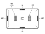
- FIG. 1 is a schematic perspective view of the illumination device according to the first embodiment.
- FIG. 2 is a top view of the illumination device according to the first embodiment.
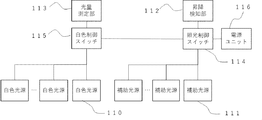
- FIG. 3 is a diagram illustrating an example of a hardware configuration of the illumination device according to the first embodiment.
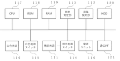
- FIG. 4 is a diagram illustrating another example of the hardware configuration of the illumination device according to the first embodiment.
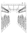
- FIG. 5 is a schematic diagram of a plant growing system.
- FIG. 6 is a diagram illustrating functional blocks of the illumination device according to the second embodiment.
- FIG. 7 is a diagram illustrating functional blocks of the illumination device according to the third embodiment.
- FIG. 8 is a schematic diagram illustrating a positional relationship between the light amount measurement unit of the illumination device and the sun.
- FIG. 9 is a diagram illustrating a data configuration example of the correction data held by the correction data holding unit.
- FIG. 10 is a diagram illustrating a system configuration of a training system according to the fourth embodiment.
- Photosynthesis is a reaction that synthesizes organic matter using light energy.
- photomorphogenesis is a morphological reaction that uses light as a signal, such as seed germination, differentiation (germination formation, leaf formation, etc.), movement (stomatal opening and closing, chloroplast movement), phototropism, etc. This is a reaction for performing Plants have multiple photoreceptors (pigments), and chlorophyll and carotenoids perform photosynthesis.
- plants also use photoreceptors (pigments) such as phytochrome, which is a photoreceptor for red light and far-red light, blue light, and near-ultraviolet (UV-A).
- phytochrome is a photoreceptor for red light and far-red light, blue light, and near-ultraviolet (UV-A).
- Certain cryptochromes and phototropins exist.
- phytochrome absorbs red light and far-red light and promotes plant photomorphogenesis such as inducing seed germination, cotyledon development, stem elongation, and phototropism.
- Plants use photoreceptors to sense the light environment and initiate a photosynthetic reaction or a photomorphogenetic reaction.
- the wavelength range (300 nm or more and 800 nm or less) that a plant can use for photosynthesis or photomorphogenesis substantially matches the wavelength range of visible light (380 nm or more and 780 nm or less).
- Radiation in the wavelength range that can be used for the reaction is called physiologically active radiation (Physiologically Active Radiation).
- Physiologically Active Radiation radiation in a wavelength range of 400 nm to 700 nm, which is an energy source for plant growth, is referred to as photosynthetically active radiation (Photosynthetically Active Radiation).
- the wavelength range of about 400 nm to about 500 nm is blue light B
- the wavelength range of about 500 nm to about 600 nm is green light G
- the wavelength range of about 600 nm to about 700 nm is red light R
- the 800 nm wavelength range may be represented by far-red light Fr.
- the index of the amount of light that is effective for photosynthesis and photomorphogenesis is expressed not by radiation flux but by photon flux or photon flux density.
- the photon flux density ( ⁇ mol ⁇ m ⁇ 2 ⁇ s ⁇ 1 ) is the number of photons reaching a unit area per unit time.
- the photon flux ( ⁇ mol ⁇ s ⁇ 1 ) is the number of photons per unit time.
- the spectral distribution of the light source that affects plant growth depends on the ratio of the photon flux in another specific wavelength range to the photon flux in a specific wavelength range R / B or the ratio R / Fr.
- R / B the ratio of the photon flux in another specific wavelength range to the photon flux in a specific wavelength range
- R / Fr the ratio of the photon flux in another specific wavelength range to the photon flux in a specific wavelength range
- FIG. 1 is a schematic perspective view of an illumination device 10 according to the first embodiment.
- FIG. 2 is a schematic top view of the lighting device 10.
- the illumination device 10 includes a plurality of white light sources 110, a plurality of auxiliary light sources 111, a first sunlight panel 132 functioning as an illumination detection unit, and a second sunlight panel 133 functioning as a light amount measurement unit 113. Further, between the rows of the white light sources 110 arranged in 2 rows ⁇ N columns (N is 1 or more), the auxiliary light sources 111 in 1 row ⁇ M columns (M is 1 or more) are arranged, and arranged in three rows. A total of two sets of white and auxiliary light sources 111 are provided.
- the arrangement of the white light source and the auxiliary light source is not limited to this. For example, a white light source and an auxiliary light source may be alternately arranged in each row, or another arrangement method may be used.
- the white light source 110 in the illumination device 10 includes a plurality of white light emitting devices 130.
- a white light emitting device 130 for example, a white LED can be adopted.
- a white LED is formed by appropriately combining a light emitting element having an emission peak in violet to blue and a phosphor emitting light in blue, green, yellow, orange, red, far red, and the like by light from the light emitting element. realizable.
- the auxiliary light source 111 in the illumination device 10 includes a plurality of auxiliary light emitting devices 131.
- the ratio R / B of the photon flux R of red light in the wavelength range of 620 nm to less than 700 nm with respect to the photon flux B of blue light in the wavelength range of 400 nm or more and 490 nm or more exceeds 4 and is 50 or less.
- a light emitting device in which the ratio R / Fr of the above-described photon flux R to the photon flux Fr of far-red light in the wavelength range of 700 nm to 780 nm is 0.1 to 10 is employed.
- Such a light emitting device includes, for example, a light emitting element having a light emission peak wavelength within a wavelength range of 380 nm to 490 nm (hereinafter sometimes referred to as a “near ultraviolet to blue region”), and light from the light emitting element.
- This can be realized by a second phosphor that emits light having an emission peak wavelength.
- the first phosphor examples include a Mn 4+ activated fluorogermanate phosphor, a Eu 2+ activated nitride phosphor, a Eu 2+ activated alkaline earth sulfide phosphor, and a Mn 4+ activated halide phosphor. Further, as the first phosphor, one kind selected from these phosphors may be used alone, or two or more kinds may be used in combination.
- the second phosphor is a first aluminate phosphor having a composition containing Al and Cr, a first element Ln containing at least one element selected from the group consisting of rare earth elements other than Ce, and Al And, if necessary, a second element M containing at least one element selected from the group consisting of Ga and In, and a composition containing Ce and Cr, and a total mole of Al and the second element M Assuming that the composition ratio is 5, the molar composition ratio of Ce is the product of the variables x and 3, the molar composition ratio of Cr is the product of the variables y and 3, and the variable x is greater than 0.0002 and exceeds 0.1. At least one phosphor selected from the group consisting of second aluminate phosphors, wherein the number is less than 50 and the variable y is more than 0.0001 and less than 0.05.
- the ratio R / B indicating the ratio of the photon flux R in the range of 620 nm to less than 700 nm to the photon flux B in the range of 380 nm to 490 nm is 2.0 to 4.0, and 700 nm.
- a light-emitting device in which R / FR indicating the ratio of the photon flux R in the range of 620 nm to less than 700 nm to the photon flux FR in the range of 780 nm or less and 0.7 to 13.0 may be employed.
- they are described as a first light emitting device 140 and a second light emitting device 141, respectively.
- the second light emitting device 141 includes, for example, a light emitting element having an emission peak wavelength in the near ultraviolet to blue region and light having at least one emission peak wavelength in a range of 580 nm or more and less than 680 nm excited by light from the light emitting element.
- a first phosphor that emits light
- a second phosphor that emits light having one or more emission peak wavelengths in the range of 680 nm to 800 nm when excited by light from the light emitting element.
- the first phosphor the same phosphor as that of the first light emitting device 140 described above can be used.
- the second phosphor includes a first element Ln containing at least one element selected from the group consisting of rare earth elements other than Ce, and a second element containing at least one element selected from the group consisting of Al, Ga and In.
- the molar composition ratio of Cr is the product of y and 3; the x is a number exceeding 0.0002 and less than 0.50; and the y is a number exceeding 0.0001 and less than 0.05. is there.
- the ratio R / B of the photon flux R of red light in the range of 620 nm to 700 nm with respect to the photon flux B of blue light in the range of 400 nm or more and 490 nm or more is more than 20 and 200 or less.
- a light emitting device may be employed.
- this is described as a third light emitting device 142.
- the third light emitting device 142 has a light emitting element having an emission peak wavelength in the near ultraviolet to blue region, and emits light having at least one emission peak wavelength in the range of 580 nm to 680 nm when excited by light from the light emitting element. This can be realized with a red phosphor.
- red phosphor examples include Eu 2+ activated nitride phosphor, Mn 4+ activated fluorogermanate phosphor, Eu 2+ activated alkaline earth sulfide phosphor, and Mn 4+ activated halide phosphor.
- the red phosphor one kind selected from these phosphors may be used alone, or two or more kinds may be used in combination.
- the auxiliary light source 111 appropriately selects a plurality of light emitting devices from among the first light emitting device 140, the second light emitting device 141, and the third light emitting device 142 as the plurality of auxiliary light emitting devices 131, and combines them. May be adopted. Further, another light emitting device, for example, a light emitting device using a red LED having no phosphor or a light emitting device using a far red LED may be adopted.
- the first light emitting device 140 and the second light emitting device 141 emit light in the red and far-red regions. Further, the first light emitting device 140 has a larger R / B than the second light emitting device 141. In other words, the first light emitting device 140 suppresses blue light emission. For example, by using together with the white light source 110 and natural light such as sunlight, it is possible to select the first light emitting device 140 when it is not necessary to supplement the blue light with the auxiliary light source 111.
- the third light emitting device 142 emits far-red light relatively less than the first light emitting device 140 and the second light emitting device 141, but can enhance red light emission.
- the third light emitting device 142 can be used.
- a light-emitting device that emits red light without emitting far-red light as the third light-emitting device 142, and a red and far-red light such as the first light-emitting device 140 or the second light-emitting device 141.
- red and far-red light can be supplemented in a well-balanced manner. Not emitting far-red light is not limited to not emitting light at all, but also includes not emitting light at all.
- the first solar panel 132 and the second solar panel 133 have solar cells and convert light energy from the sun into electric power.
- the first solar panels 132 are provided on each side surface of the lighting device 10, and a plurality of first solar panels 132 are attached to the lighting device 10.
- the elevation detector 112 that detects the elevation of the sun based on the value of the electric power converted by the first solar panel 132 is realized.
- the second sunlight panel 133 is provided on the upper surface of the lighting device 10, and one or more second sunlight panels 133 are attached to the lighting device 10. Based on the value of the electric power converted by the second solar panel 133, the light amount measuring unit 113 that measures the amount of light illuminated by natural light such as sunlight regardless of the illumination device 10 is realized.
- FIG. 3 is a diagram illustrating an example of a hardware configuration of the illumination device 10.
- the illumination device 10 includes a power supply unit 116, an illumination control switch 114, and a white control switch 115, in addition to the plurality of white light sources 110 and the auxiliary light sources 111, the elevation detection unit 112, and the light amount measurement unit 113 described above.
- the power supply unit 116 supplies electric power for performing supplementary light by the white light source 110 and the auxiliary light source 111.
- the illumination control switch 114 controls supplementary light by the white light source 110 and the auxiliary light source 111 by controlling ON / OFF of power supply.
- the white control switch 115 controls the supplementary light by the white light source 110.
- the white light source 110 When the illumination control switch 114 is OFF, the white light source 110 does not emit light even when the white control switch 115 is ON. Further, even if the illumination control switch 114 is ON, if the white control switch 115 is OFF, the white light source 110 does not emit light.
- FIG. 4 is a diagram illustrating another example of the hardware configuration of the illumination device 10. 3 in that it includes a plurality of white light sources 110 and auxiliary light sources 111, a lifting / lowering detection unit 112, a light amount measurement unit 113, a power supply unit 116, an illumination control switch 114, and a white control switch 115.
- the plurality of white light sources 110 and the auxiliary light sources 111 are shown in one block diagram.
- the communication I / F 121, the ROM 118 (Read Only Memory), the RAM 119 (Random Access Memory), the CPU 117 (Central Processing Unit), and the HDD 120 (Hard Disk Drive) are further provided. Each of these hardware is connected by a bus.
- the communication I / F 121 is an interface for connecting to a network.
- the HDD 120 is a non-volatile storage device that stores programs and data.
- the ROM 118 is a nonvolatile semiconductor memory that can retain programs and data even when the power is turned off.
- the RAM 119 is a volatile semiconductor memory that temporarily stores programs and data.
- the CPU 117 is an arithmetic unit that reads out programs and data from a storage device such as the ROM 118 and the HDD 120 onto the RAM 119 and executes processing to realize control and functions of the entire lighting device 10.
- the CPU 117 controls light emission control of the white light source 110 and the auxiliary light source 111 in the illumination device 10. Specifically, the value of the power obtained by the first solar panel 132 or the second solar panel 133 is obtained, and the illumination control switch 114 or the white control switch 115 is turned on or off based on the obtained value. It is determined whether or not to do this, and this is controlled.
- FIG. 5 shows a system configuration diagram of the breeding system 1 having the illumination device 10.
- a plurality of lighting devices 10 are installed on the ceiling of the green house 20.
- Each illuminating device 10 is connected to the wiring similarly stretched on the ceiling and receives power supply.
- the ceiling and side surfaces of the green house 20 are covered with translucent glass, vinyl, or the like, so that light from the sun reaches the green house 20.
- the greenhouse 20 is made of a translucent material in order to capture natural light such as sunlight as much as possible.
- natural light such as sunlight is strong, for example, in a country just below the equator, if natural light is taken as it is, the light is too strong and plants may not grow.
- a green house 20 having a transmittance of about 60% to 80% in the wavelength ranges of R, G, B, and Fr.
- the illumination control switch 114 is turned off when power of a predetermined value or more is not obtained from any of the plurality of first solar panels 132, whereby the illumination by the white light source 110 and the auxiliary light source 111 is stopped. . Further, while power is supplied from the power supply unit 116 and power of a predetermined value or more is obtained by any of the plurality of first solar panels 132, the switch ON state is maintained.
- the predetermined value is set to be a first threshold value for distinguishing between a state where the sun has set at night and a state where the sun has not set.
- the first threshold is set.
- the first threshold value may be any value as long as the illumination by the white light source 110 and the auxiliary light source 111 can be controlled in accordance with the rise and fall of the sun, even if a slight time lag occurs.
- the first solar panel 132 is provided on each side surface of the lighting device 10 and can provide a degree of freedom of arrangement when determining the direction of the lighting device 10 in accordance with the rising and falling of the sun. Since the light from the white light source 110 and the auxiliary light source 111 is emitted toward the plants, the white light source 110 and the auxiliary light source 111 face the ground. In addition, the direction in which the illuminating devices 10 are arranged is also adjusted according to the arrangement of the plants. Therefore, a detection area for measuring the irradiance of light is provided on each side surface of the illumination device 10 so that the rising and falling of the sun can be appropriately detected.
- the elevation detection unit 112 in the illumination device 10 according to the first embodiment has at least a first detection area for detecting sunrise and a second detection area for detecting sunset.
- a first solar panel 132 is provided on each of opposing side surfaces. This first solar panel 132 may be physically separate, or may be constituted by one solar panel.
- the supplementary light by the illumination device 10 is operated by the elevation detection unit 112 in accordance with the elevation of the sun. That is, when the day rises, the power obtained from the first solar panel 132 in at least the first detection area is changed from the state in which power equal to or higher than the first threshold is not obtained from any of the first solar panels 132 to the first. The state changes to a state that is equal to or larger than the threshold. As a result, when the sun rises, the illumination control switch 114 is turned on, and the white light source 110 and the auxiliary light source 111 start supplementary light.
- the illumination control switch 114 is turned off, and the supplementary light by the white light source 110 and the auxiliary light source 111 ends until the next morning. .
- the side surface of the illumination device 10 is directed upward, that is, inward from the position where the white light source 110 and the like are arranged and intersects with the light emitting surface that performs illumination, in the direction in which the second solar panel 133 is arranged. It is inclined. This takes into account the influence of the light from the white light source 110 and the auxiliary light source 111 in the power conversion by the first solar panel 132. In other words, even after the sun sets, if the light from the white light source 110 and the auxiliary light source 111 generates power equal to or greater than a predetermined value, control is performed such that the illumination control switch 114 is turned off in accordance with sunset. Will not work.
- the value of the first threshold is set by correcting (upwardly correcting) the influence of the light from the white light source 110 and the auxiliary light source 111, a situation may occur in which the light does not turn on even when the day rises.
- a method of adding a light-shielding plate so that light from the white light source 110 and the auxiliary light source 111 does not reach would hinder the use of natural light such as the sun.
- the inclination is provided as a structure in which the electric power obtained from the first solar panel 132 is not affected by the light from the white light source 110 and the auxiliary light source 111 as much as possible and does not disturb the irradiation with natural light.
- the inclination does not have to be provided, and it can be realized by another method such as correction.
- the white control switch 115 When the power converted by the second solar panel 133 is equal to or more than a predetermined value, the white control switch 115 is turned off and the power supply to the white light source 110 is stopped. As a result, the light emission by the white light source 110 is interrupted, and the state is switched to the state where the supplementary light by the auxiliary light source 111 is continued. Thus, when natural light such as the sun is irradiating the plant with sufficient light, it is possible to perform control to stop the illumination by the white light source 110.
- ⁇ ⁇ ⁇ Suppressing excessive irradiation by supplementary light from the white light source 110 not only provides a good growth environment but also leads to energy saving.
- a second threshold value that is a lower limit for determining that sufficient light has reached the plant. Since this value can vary depending on which plant is grown, it is preferable to set the value based on an appropriate amount of white light that promotes the growth of the plant. At least the second threshold value is higher than the first threshold value.
- the white control switch 115 is turned on and the light emission by the white light source 110 is restarted.
- the illumination control switch 114 is OFF, the white light source 110 does not emit light. Accordingly, the ON / OFF of the supplementary light by the white light source 110 is controlled during the daylight hours, but after sunset, the white light source 110 does not emit light until the illumination control switch 114 is turned ON by sunrise.
- the white light control switch 115 does not have to stop the supplementary light by all the white light sources 110.
- the supplementary light by some white light sources 110 may be stopped, or the emission of light by some white light emitting devices 130 may be stopped.
- a process of weakening or increasing the strength may be performed. That is, the degree of light irradiation by the white light source 110 may be increased so as to compensate for the decrease in light due to natural light, and may be decreased so as to eliminate excess light when the light becomes stronger.
- the light amount measurement unit 113 may be configured by one second solar panel 133 or may be configured by a plurality of second solar panels 133.
- the illuminating device 10 in the breeding system 1 includes the illuminating control unit that controls the supplementary light (the degree of light irradiation) by the white light source 110 and the auxiliary light source 111 in accordance with the rising and falling of the sun. .
- it has illumination control means for controlling the supplementary light by the white light source 110 according to the irradiance (degree of illumination) of the light by natural light. Accordingly, the start and end of the supplementary light (irradiation control) by the white light source 110 or the auxiliary light source 111 can be dynamically controlled in accordance with the cycle of the day from sunrise to sunset.
- the elevation detecting unit 112 gives an elevation parameter according to the irradiance, and the illumination control unit controls the supplementary light based on the elevation parameter and the first threshold.
- the light quantity measuring unit 113 gives a light quantity parameter according to the irradiance, and the illumination control means controls the supplementary light based on the light quantity parameter and the second threshold.
- the elevation parameters given by the elevation detection unit 112 are not limited to sunrise and sunset, and are designed so that the detection sensitivity at sunrise and sunset is high.
- the light amount parameter provided by the light amount measurement unit 113 is not limited to sunrise and sunset, and is designed so that the measurement sensitivity at noon (when the sun is at the highest position) is higher than at sunrise and sunset. .
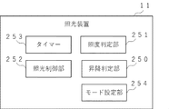
- FIG. 6 is a functional block diagram illustrating functions of the illumination device 11 in the training system 1 according to the second embodiment.
- Various functions and processes described with reference to FIG. 6 are realized by the operation of the CPU 117 in the illumination device 11 having the hardware configuration illustrated in FIG. 4, for example. Therefore, the hardware configuration of the illumination device 11 according to the second embodiment may be the same as the illumination device 10 according to the first embodiment.
- the breeding system 1 in addition to the control for linking ON / OFF of the supplementary light with the elevation of the sun as described in the first embodiment, emits light to the plant for a longer time than the sunshine time of the sun. Provide a mechanism for irradiating.
- the elevation determination unit 250 determines the elevation of the sun based on the elevation parameters obtained by the elevation detection unit 112.
- the illuminance determination unit 251 determines the degree of illumination based on the light amount parameter obtained by the light amount measurement unit 113.
- the illumination control unit 252 controls whether or not to perform supplementary light with the white light source 110 and the auxiliary light source 111 based on the result of the determination by the elevation determination unit 250. Further, based on the result of the determination by the illuminance determination unit 251, it controls whether or not the white light source 110 performs supplementary light. Further, based on the timer 253, it controls whether or not the white light source 110 and the auxiliary light source 111 perform the supplementary light.
- the mode setting unit includes a first mode in which the supplementary light is linked to the rise and fall of the sun, a second mode in which the supplementary light for a predetermined time starts in conjunction with the sunrise, and a third mode in which the supplementary light for a predetermined time ends in conjunction with the sunset.
- These settings can be made, for example, by receiving an input from a computer connected to the network via the communication I / F 121.
- the timer 253 notifies the elapse of the set supplementary light time.
- Operation control of the illumination device 11 in the breeding system 1 according to the second embodiment differs depending on the set mode.
- the operation control in the first mode is the same as the operation control performed by the lighting device 11 of the first embodiment.
- the white light Light emission of the white light source 110 is started by the control unit, light emission of the auxiliary light source 111 is started by the auxiliary light control unit, and the timer 253 is started. From the start to the end of the timer 253, the determination by the illuminance determination unit 251 is valid, and it is determined that the light amount parameter indicating the power value obtained from the second solar panel 133 is equal to or larger than the second threshold. In this case, the white light control unit stops the emission of the white light source 110. At this time, the emission of the white light source 110 is stopped even if the elevation parameter is equal to or greater than the first threshold.
- the illuminance determination unit 251 determines that the light amount parameter indicating the power value obtained from the second solar panel 133 is smaller than the second threshold, the light emission of the white light source 110 is restarted. Until the timer 253 ends, the light emission control of the white light source 110 by the illuminance determination unit 251 functions.
- the elevating / decreasing determination unit 250 does not perform sunset determination. That is, it is not determined whether the elevation parameter is less than the first threshold. Instead, when the timer 253 expires, the white control unit stops the emission of the white light source 110, and the auxiliary light control unit stops the emission of the auxiliary light source 111. Thus, at the stage where the supplementary light time has elapsed from the sunrise, the supplementary light by the illumination device 11 is stopped until the next sunrise.
- stop control of the supplementary light is performed based on the elapse of the predetermined time, the supplementary light amount may be gradually reduced, and the supplementary light may be stopped over a certain period of time.
- the timer 253 starts when the elevating / decreasing determination unit 250 determines that the elevating / lowering parameter is less than the first threshold.
- the timer 253 notifies the end when the time obtained by subtracting the light supplement time from the time of the day elapses.
- the emission of the white light source 110 is started by the white light control unit, and the emission of the auxiliary light is started by the auxiliary light control unit.
- the control of the white light source 110 based on the determination by the illuminance determination unit 251 functions effectively while the timer 253 is OFF, that is, from the notification of the end of the timer 253 to the start of the timer 253. Thereby, the lapse of the supplementary light time can be adjusted to the sunset.
- the timing of the start of the supplementary light is determined based on the sunset time of the previous day, the sunset time of the next day and the timing of the end of the supplementary light do not greatly differ from each other. Can be.
- the breeding system 1 of the second embodiment it is possible to appropriately set, according to the user's intention, whether to perform the supplementary light according to the sunshine time or to perform the supplementary light longer than the sunshine time. In addition, it is possible to set that light supplement is performed for a shorter time than the sunshine time.
- the user can select one control pattern from the plurality of control patterns, and the illumination device 11 holds the selected control pattern as a setting.
- mode control can be set for each lighting device 11, it is possible to control some cultivation sections and other cultivation sections in the green house 20 in different modes.
- the supplementary light is controlled in the first mode to cultivate the vegetables according to the summertime when the sunshine time is long.
- the cultivation section it is possible to selectively use the supplementary light in the second mode or the third mode.
- the lighting device 11 that can set an arbitrary mode from the first mode to the third mode has been described, but has a mode selection function. You do not have to. That is, the lighting device 11 corresponding to each mode may be prepared, and the lighting device 11 corresponding to the mode to be used may be installed. In that sense, the illuminating device 11 having no mode setting unit can also constitute the breeding system 1 according to the second embodiment.
- first solar panel 132 In the case where the lighting device 11 corresponding to the second mode or the lighting device 11 corresponding to the third mode is realized, only one first solar panel 132 may be used. If it is sufficient to detect either the sunrise or the sunset, if the illuminating device 11 is arranged so that the first solar panel 132 matches the direction of the sunrise or the sunset, 1 The first sunlight panel 132 can control the supplementary light.
- the second solar panel 133 is installed on the upper surface.
- the installation surface is not limited to the upper surface, the position of the sun moves with time while the second solar panel 133 is installed facing a specific surface. Therefore, if the light receiving area of the second solar panel 133 does not move following the movement of the sun, the light receiving condition of the second solar panel 133 changes, and, for example, light of the same intensity is emitted from the sun. Even so, the value of the power converted by the second solar panel 133 may be different.
- a hemispherical arrangement surface is formed on the surface on which the second sunlight panel 133 is arranged, that is, on the surface opposite to the surface on which the light source is arranged, and the plurality of second sunlight panels 133 are arranged on the hemisphere.
- the second solar panel 133 that has obtained the largest power among the plurality of second solar panels 133 may be regarded as the second solar panel 133 that is arranged at a position facing the sun. It depends on the arrangement of multiple solar panels. If a large number of small-area solar panels are laid so as to cover the hemisphere, the accuracy is improved. However, it is expected that the structure of the device will be complicated and the cost will increase accordingly.
- the realization of the growing system 1 having such an illuminating device is also included in the disclosure of the present invention, but another realizing method will be described for the illuminating device 12 in the cultivating system 1 according to the third embodiment.
- the breeding system 1 according to the third embodiment holds correction data obtained by measurement in advance, and suppresses a difference in light receiving conditions based on the correction data.
- the first embodiment and the second embodiment It is possible to perform illuminance determination with higher accuracy than that.
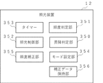
- FIG. 7 is a functional block diagram of the lighting device 12 according to the third embodiment.
- Various functions and processes described with reference to FIG. 7 are realized by the operation of the CPU 117 in the illumination device 12 having the hardware configuration illustrated in FIG. 4, for example. Therefore, the hardware configuration of the illumination device 12 according to the second embodiment may be the same as the illumination device 10 according to the first embodiment.
- the illumination device 12 is different from the illumination device 11 of the second embodiment in that the illumination device 12 includes an illuminance correction unit 355 and a correction data holding unit 356.
- the correction data holding unit 356 holds correction data for determining a correction parameter indicating a correction amount for the light amount parameter obtained by the light amount measurement unit 113.
- the illuminance correction unit 355 determines a correction parameter for the obtained light amount parameter and performs correction.
- the illuminance determination unit 351 determines whether or not the light amount is equal to or greater than a second threshold based on the corrected light amount parameter.
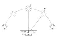
- FIG. 8 is a schematic diagram simply showing the positional relationship between the illumination device 12 and the sun in order to explain the correction data to be obtained.
- the illumination device 12 is fixedly installed, and therefore, the light amount measuring unit 113 is also fixedly installed on the upper surface.
- the angle formed by the light amount measurement unit 113 and the sun changes. For example, suppose that the sun was located at T1 shown in FIG. 8 at time t1. At this time, in order to measure the amount of natural light from the sun located at T1 from the front, it is necessary to tilt the second solar panel 133 by the angle ⁇ .
- the difference between the value of the light amount measured in a state directly facing the sun and the light amount measured in a state inclined by the angle ⁇ is stored as correction data, the difference can be measured by the second solar panel 133. Based on the measured light amount, the light amount in a state directly facing the sun can be calculated.
- the correction data is data indicating the difference.
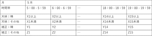
- FIG. 9 shows an example of a data configuration example of the correction data held in the correction data holding unit 356.
- the correction data has items of a month, a time zone, a weather section, and a correction parameter, and a weather determination condition and a correction parameter are set for each weather section.
- Correction data is prepared for one year for each month, but FIG. 9 shows correction data for May as an example.
- the correction data may be provided not in units of months but in smaller units, such as every two weeks, or may be provided in units of seasons over a plurality of months.
- the correction data for each month is further divided by time zone. In the example of FIG. 9, the interval is divided every hour. However, the interval may be divided at shorter time intervals or at longer time intervals.
- the weather judgment condition and the correction parameter according to the weather are determined according to the month and the time zone.
- “weather: fine” and “weather: other” are provided as weather classifications, and the weather is divided according to whether it is fine or not. In addition, you may divide a weather division more finely. For example, since there is a difference in the degree of fineness, the fineness may be finely divided, and what kind of weather classification can be set as appropriate. According to each of the classified weather, a weather judgment condition for judging that the weather is classified is determined.
- Weather determination conditions are determined from measurement values obtained under the same conditions as the measurement conditions when the illuminating device 12 is installed in the breeding system 1 in the time zone of the day corresponding to the weather classification. Since the correction process is performed according to the determined weather division, it is necessary to determine the weather division from the light amount parameter before correction. Therefore, it is preferable that measurement values obtained in a certain time zone of a certain month are divided into weather sections and totaled, and the measurement results totaled for each weather section are compared to determine condition values that do not overlap each other. In the example of FIG. 9, between 5:00 and 6:00, if the light amount parameter obtained from the light amount measured by the second solar panel 133 is X1 or more, it is determined to be a fine weather category, and it is less than X1. If so, the weather determination condition is set so as to determine the other weather classification.
- the correction parameters are determined according to the weather classification. Based on the example of FIG. 9, the correction parameter when the weather section is sunny in the corresponding month and time zone is obtained from the measurement result in the corresponding time zone on the day corresponding to the sunny weather section. Specifically, a measurement value obtained under the same conditions as the measurement conditions when the illuminating device 12 is installed in the breeding system 1 and a measurement value when facing the sun are measured and determined based on the difference. Is done. In addition, it may be determined based on a value calculated statistically or averagely from the measurement results on a plurality of sunny days. The other weather conditions are determined in the same manner, and correction parameters are determined for each weather condition. In the example of FIG. 9, between 5:00 and 6:00, the correction is performed based on the correction parameter Y1 if the weather classification is fine, and the correction is performed based on the correction parameter Z1 if the weather classification is other.
- the illuminance correction unit 355 performs a correction process using the correction data stored in the correction data storage unit 356. Specifically, when the light amount parameter obtained by the light amount measurement unit 113 is acquired, the month and time zone corresponding to the acquisition time are specified. Next, from the weather determination conditions in the specified month and time zone, a weather category to which the obtained light amount parameter corresponds is determined. In the example of FIG. 9, it is determined whether or not it is sunny. Then, a correction parameter corresponding to the specified month and time zone and the determined weather section is acquired, and the light amount parameter is corrected based on the correction parameter. After that, the illuminance determination unit 351 acquires the corrected light quantity parameter, and performs illuminance determination based on the corrected light quantity parameter.
- the correction parameter taking into account the difference between the measurement result of the light amount measurement in the illumination device 12 and the measurement condition actually facing the sun is held, and the correction is performed using the correction parameter. Will accurately reflect the irradiance actually radiated to the plant. Therefore, the accuracy of the control based on the determination result by the illuminance determination unit 351, that is, the control of stopping the supplementary light by the white light source 110 when the irradiance by natural light is sufficient is also improved.
- the result of performing the correction using the correction parameter of the fine weather is sufficient. It is possible to avoid a situation where it is determined that radiation has been obtained and the supplementary light by the white light source 110 stops.
- one weather section is specified from the plurality of weather sections, and the supplementary light control is performed by the light amount parameter corrected based on the weather section, thereby performing the supplementary light control according to the weather section.
- the supplementary light amount of the white light source may be adjusted based on the corrected light amount parameter. For example, a necessary amount of white light may be set, and a white light source that only compensates for the difference between the set value and the corrected light amount parameter may be supplemented by the illumination device. Further, the auxiliary light of the auxiliary light source may be controlled according to the weather section, or the auxiliary light of both the white light source and the auxiliary light source may be controlled.
- the fourth embodiment is another configuration example of the breeding system 1 described in the first to third embodiments.
- FIG. 10 shows a system configuration of the breeding system 1 according to the fourth embodiment.
- the breeding system 1 according to the fourth embodiment is different in that it has an environment measuring device 40 and a control device 30.
- the illuminating device 13 according to the fourth embodiment is different from the illuminating device 13 according to the first embodiment in that the illuminating device 13 does not include the light amount measuring unit 113 and the elevation detecting unit 112. Therefore, the illumination device 13 according to the fourth embodiment does not need to include the first solar panel 132 and the second solar panel 133.
- the measurement performed using the first solar panel 132 and the second solar panel 133 in the illumination device 13 is performed by the environment measurement device 40 in the training system 1 of the fourth embodiment. Therefore, the environment measuring device 40 is arranged at a position where it does not disturb the cultivation section, and is installed, for example, on the green house 20. In the environment measuring device 40, the elevating parameter and the light amount parameter are measured, and other detailed measurement may be performed.
- the control device 30 can be configured by a general computer including a CPU, a ROM, a RAM, a HDD, a communication I / F, and the like, and a measurement result obtained by the environment measurement device 40 is transmitted to the control device 30. .
- the control device 30 controls the white light source 110 and the auxiliary light source 111 for each lighting device 13 based on the measurement result. That is, in the control device 30, the up / down determination and the illuminance determination are performed, and the ON / OFF of the illumination control switch 114 and the white control switch 115 of the illumination device 13 is controlled based on the determination result.
- the specific control is the same as that described in the first to third embodiments.
- each illumination device 13 it is not necessary to provide each illumination device 13 with a configuration for environmental measurement such as the elevation detection unit 112 and the light amount measurement unit 113, and a large number of illumination devices 13 are arranged.
- advantages such as cost merit, centralized control, and unified management can also occur.
- the first phosphor preferably includes a nitride phosphor having a composition including at least one element selected from Sr and Ca, Eu, Al, and Si.
- a nitride phosphor represented by (Sr, Ca) AlSiN 3 : Eu as a composition formula can be given.
- a plurality of elements separated by commas (,) in a composition formula means that at least one of the plurality of elements is contained in the composition. .
- the plurality of elements described by being separated by commas (,) in the composition formula includes at least one element selected from the plurality of elements separated by commas in the composition, and two of the plurality of elements are included. A combination of the above may be included.
- the part before the colon (:) indicates a host crystal
- the part after the colon (:) indicates an activating element.
- the first phosphor preferably includes a nitride phosphor having a composition represented by the following formula (I).
- p and q are numbers satisfying 0 ⁇ p ⁇ 1.0, 0 ⁇ q ⁇ 0.5, and 0 ⁇ p + q ⁇ 1.0.
- Eu is an activating element of the nitride phosphor.
- the variable q is a molar composition ratio of the activating element Eu in the composition represented by the formula (I).
- the variable q is preferably 0.0001 ⁇ q ⁇ 0.4, more preferably 0.001 ⁇ q ⁇ 0.3, and still more preferably 0.0015 ⁇ q ⁇ 0.2.
- the variable p is a molar composition ratio of Sr in the composition represented by the formula (I).
- the variable p is preferably 0.001 ⁇ p ⁇ 0.9, more preferably 0.002 ⁇ p ⁇ 0.8, and still more preferably 0.003 ⁇ p ⁇ 0.76.
- the first phosphor may include a Eu2 + activated nitride phosphor different from the nitride phosphor having the composition represented by the formula (I).
- the Eu 2+ -activated nitride phosphor is a group consisting of an alkaline earth metal element in addition to a nitride phosphor having a composition including at least one element selected from Sr and Ca, Eu, Al, and Si.
- Phosphors containing at least one element selected from the group consisting of at least one element selected from the group consisting of alkali metal elements and containing aluminum nitride activated by Eu 2+ can be used.
- the halide phosphor activated by Mn 4+ is at least one element or ion selected from the group consisting of an alkali metal element and an ammonium ion (NH 4 + ), and a group consisting of a Group 4 element and a Group 14 element. It is preferable that the phosphor has a composition containing at least one element selected from the group consisting of: and a fluoride activated by Mn 4+ .
- the first phosphor may include at least one phosphor selected from the group consisting of phosphors having any composition represented by the following formulas (II) to (VI).
- M 1 is at least one selected from the group consisting of Al, Ga and In, and i, j, k, m, n and v are respectively 2 ⁇ i ⁇ 4, 0 ⁇ j ⁇ 0.5, 0 ⁇ k ⁇ 1.5, 0 ⁇ m ⁇ 1.5, 0 ⁇ n ⁇ 0.5, and 0 ⁇ v ⁇ 0.05.
- M 2 is at least one element selected from the group consisting of Ca, Sr, Ba and Mg
- M 3 is at least one element selected from the group consisting of Li, Na and K
- M 4 is at least one element selected from the group consisting of Eu, Ce, Tb and Mn
- d, e, f, g and h are each 0.80 ⁇ d ⁇ It is a number that satisfies 1.05, 0.80 ⁇ e ⁇ 1.05, 0.001 ⁇ f ⁇ 0.1, 0 ⁇ g ⁇ 0.5, 3.0 ⁇ h ⁇ 5.0.
- Cr In the first aluminate phosphor contained in the second phosphor, Cr is an activating element. In the second aluminate phosphor, Ce and Cr are activating elements. In the composition of the second aluminate phosphor, when the total molar composition ratio of Al and the second element M is 5, the molar composition ratio of Ce is represented by the product of the variable x and 3, and the molar composition of Cr is When the composition ratio is expressed by the product of the variable y and 3, the variable x is a number that exceeds 0.0002 and satisfies less than 0.50 (0.0002 ⁇ x ⁇ 0.50), and the variable y is 0.
- the activation amount of Ce as a luminescence center contained in the crystal structure of the second aluminate phosphor is increased.
- the activation amount of Cr is in the optimal range, and it is possible to suppress a decrease in emission intensity due to a decrease in the number of emission centers, and conversely, to suppress a decrease in emission intensity due to concentration quenching caused by an increase in the activation amount, The emission intensity can be increased.
- the second phosphor includes a first aluminate phosphor having a composition represented by the following formula (VII) and a second aluminate phosphor having a composition represented by the following formula (VIII). It is preferable to include at least one phosphor selected from the group consisting of: (Al 1-w Cr w ) 2 O 3 (VII) In the formula (VII), w is a number satisfying 0 ⁇ w ⁇ 1.
- Ln is at least one rare earth element selected from the group consisting of rare earth elements other than Ce
- M is at least one element selected from the group consisting of Ga and In
- x , Y, and z are numbers that satisfy 0.0002 ⁇ x ⁇ 0.50, 0.0001 ⁇ y ⁇ 0.05, and 0 ⁇ z ⁇ 0.8.
- the second phosphor includes at least one aluminate phosphor, and may include two or more aluminate phosphors.
- Cr contained in the first aluminate phosphor having the composition represented by the formula (VII) is an activating element.
- the product of the variable w and 2 is the molar composition ratio of the activating element Cr in the composition represented by the formula (VII).
- the variable w is preferably 0 ⁇ w ⁇ 1, more preferably 0.00005 ⁇ w ⁇ 0.25, still more preferably 0.0005 ⁇ w ⁇ 0.15, and even more preferably 0.001 ⁇ w ⁇ 0. 07.
- Cr which is an activator serving as an emission center, is included, and the emission intensity can be increased.
- CCe and Cr in the formula (VIII) are activation elements of the second aluminate phosphor having the composition represented by the formula (VIII).
- the product of the variable x and 3 is the molar composition ratio of the activating element Ce in the composition represented by the formula (VIII).
- the variable x is preferably 0.0002 ⁇ x ⁇ 0.50, more preferably 0.001 ⁇ x ⁇ 0.35, and still more preferably 0.0015 ⁇ x ⁇ 0.30.
- the product of the variable y and 3 is a molar composition ratio of the activating element Cr in the composition represented by the formula (VIII).
- the variable y is preferably 0.0001 ⁇ y ⁇ 0.05, more preferably 0.0005 ⁇ y ⁇ 0.04, and still more preferably 0.001 ⁇ y ⁇ 0.026.
- Ln is at least one rare earth element selected from the group consisting of rare earth elements other than Ce, and is more preferably selected from the group consisting of Y, Gd, Lu, La, Tb and Pr. And at least one selected from the group consisting of Y, Gd and Lu.
- M is preferably at least one element selected from the group consisting of Ga and In, and M preferably contains Ga.
- the product of the variable z and 5 is the molar composition ratio of the element M that replaces Al in the formula (VIII).
- the variable z is preferably 0 ⁇ z ⁇ 0.8, more preferably 0.001 ⁇ z ⁇ 0.6, and still more preferably 0.01 ⁇ z ⁇ 0.4. It is.
- At least one aluminate phosphor contained in the second phosphor has a composition constituting a garnet structure, and thus is resistant to heat, light and moisture.
- the at least one aluminate phosphor contained in the second phosphor has an absorption peak wavelength of an excitation absorption spectrum of about 380 nm or more and about 470 nm, and sufficiently absorbs light from the light emitting element to emit light of the second phosphor. Strength can be increased.
- the at least one aluminate phosphor contained in the second phosphor is, for example, (Al 0.09 Cr 0.01 ) 2 O 3 or (Al 0.9943 Cr 0.0057 ) 2 O.
- the mass ratio of the second phosphor to the total amount of 100% by mass of the first phosphor and the second phosphor is such that the red light in the wavelength range of 620 nm to 700 nm with respect to the photon flux B of blue light in the wavelength range of 400 nm to 490 nm. And the ratio R / B of the photon flux R to the photon flux Fr of far-red light in the wavelength range of 700 nm or more and 780 nm or less. The amount is 1 or more and 10 or less.
- the mass ratio of the second phosphor to the total amount of 100 mass% of the first phosphor and the second phosphor is preferably in the range of 0.5% by mass to 99.5% by mass, more preferably 1% by mass.
- % By mass to 99% by mass, more preferably 1% by mass to 90% by mass, still more preferably 2% by mass to 80% by mass, and still more preferably 5% by mass to 80% by mass.
- the range is from not less than 10% by mass to not more than 78% by mass, particularly preferably not less than 10% by mass and not more than 75% by mass.
- the ratio R / B of the light quantum flux R to the light quantum flux B exceeds 4 and is 50 or less
- the mixed-color light can be controlled such that light having a ratio R / Fr of the light quantum flux R to the light quantum flux Fr of 0.1 to 10 is irradiated.
- the mass ratio of the second phosphor to the total amount of 100 mass% of the first phosphor and the second phosphor is in the range of 2% by mass or more and 80% by mass or less, the ratio of the photon flux R to the photon flux B is reduced.
- the ratio R / B can be more than 10 and 38 or less, the ratio R / Fr of the photon flux R to the photon flux Fr can be 1.5 or more and 4.12 or less, and the photoreception of the plant A light-emitting device which emits light which is more easily absorbed by the body and which facilitates photomorphogenesis can be provided.
- the mass ratio of the second phosphor to the total amount of 100 mass% of the first phosphor and the second phosphor is more than 10 mass% and 75 mass% or less, the ratio of the photon flux R to the photon flux B is increased.
- the ratio R / B can be more than 10 and not more than 38, the ratio R / Fr of the photon flux R to the photon flux Fr can be 1.5 or more and 4.0 or less, and the photoreception of the plant It is possible to provide a light-emitting device which emits light which is more easily absorbed by the body and which facilitates photomorphogenesis.
- the red phosphor has a composition of at least one element selected from Sr and Ca and Al and contains silicon nitride activated by Eu 2+ (hereinafter, referred to as “CASN phosphor”). In some cases).
- the red phosphor has a composition of at least one element selected from the group consisting of alkaline earth metal elements and at least one element selected from the group consisting of alkali metal elements, and is activated by Eu 2+.
- the red phosphor examples include a phosphor represented by the following formula (IX) or (X) or any one of the above formulas (II) and (IV) to (VI).
- the red phosphor preferably contains a phosphor containing silicon nitride having a composition represented by the following formula (IX).
- a phosphor containing any of the compositions represented by the following formulas (IX) or (X) or the above formulas (II), (IV) to (VI) emits red light by excitation light from a light emitting element.
- the emission peak present in the range of 580 nm to 680 nm has a half width of 40 nm or more, and the emission peak has a relatively broad shape. Since the emission peak of the red phosphor 70 present in the range of 580 nm or more and 680 nm or less has a relatively broad shape with a half width of 40 nm or more, photoreceptors of more types of plants can be supplemented with light. Can absorb the red light as light energy, or can sense the supplemented red light as a light signal, can stably promote the growth of the plant, or can enhance the functional nutritional component of the plant , Can supply red light.
- the phosphor containing the composition represented by the formula (IX) may be referred to as a CaAlSiN 3 : Eu phosphor or a (Sr, Ca) AlSiN 3 : Eu phosphor.
- the variable t is a molar ratio of the activating element Eu in the composition represented by the formula (IX).
- the variable t is preferably 0.0001 ⁇ t ⁇ 0.2, more preferably 0.0001 ⁇ t ⁇ 0.1, and even more preferably 0.0002 ⁇ t ⁇ 0.05.
- the variable s is a molar ratio of Sr in the composition represented by the formula (IX).
- the variable s is preferably 0 ⁇ s ⁇ 0.98, more preferably 0 ⁇ s ⁇ 0.95, and still more preferably 0 ⁇ s ⁇ 0.9.
- the ratio R / B of the photon flux R of red light in the range of 620 nm to 700 nm with respect to the photon flux B of blue light in the range of 400 nm or more and 490 nm or less exceeds 20 and is 200 or less.
- another type of phosphor that emits light in a wavelength region other than the red light wavelength region may be included.
- Other types of phosphors include a green phosphor that emits green light and a yellow phosphor that emits yellow by absorbing a part of the light emitted from the light emitting element, and has an emission peak wavelength exceeding 680 nm. And a far-red phosphor.
- the green phosphor include a phosphor represented by the following formulas (i) to (iii) and having any composition.
- M 11 is at least one selected from the group consisting of Ca, Sr, Ba and Zn
- X11 is at least one selected from the group consisting of F, Cl, Br and I.
- Si 6-b Al b O b N 8-b Eu
- b satisfies 0 ⁇ b ⁇ 4.2.
- M 13 Ga 2 S 4 : Eu (iii) Wherein (iii), M 13 is at least one selected from Mg, Ca, the group consisting of Sr and Ba.
- examples of the green phosphor include silicate phosphors such as (Ca, Sr, Ba) 2 SiO 4 : Eu and Ca 3 Sc 2 Si 3 O 12 : Ce.
- yellow phosphor examples include phosphors represented by the following formulas (iv) to (v) and having any composition.
- the far-red phosphor having an emission peak wavelength in a range exceeding 680 nm include phosphors represented by the following formulas (vi) to (xi) and having any composition.
- f is a number satisfying 0 ⁇ f ⁇ 1.
- Ln is at least one rare earth element selected from the group consisting of rare earth elements other than Ce
- M 16 is at least one element selected from the group consisting of Ga and In
- x, y and z are numbers satisfying 0.0002 ⁇ x ⁇ 0.50, 0.0001 ⁇ y ⁇ 0.05, and 0 ⁇ z ⁇ 0.8.
- CaYAlO 4 Mn
- CdS Ag
- GdAlO 3 Cr
- the device or system described in each embodiment can be used for growing plants.
- Control device 40 Environment measurement device
Landscapes
- Chemical & Material Sciences (AREA)
- Engineering & Computer Science (AREA)
- Life Sciences & Earth Sciences (AREA)
- Inorganic Chemistry (AREA)
- Materials Engineering (AREA)
- Organic Chemistry (AREA)
- Environmental Sciences (AREA)
- Forests & Forestry (AREA)
- Ecology (AREA)
- Botany (AREA)
- Biodiversity & Conservation Biology (AREA)
- General Engineering & Computer Science (AREA)
- Cultivation Of Plants (AREA)
- Greenhouses (AREA)
- Circuit Arrangement For Electric Light Sources In General (AREA)
Abstract
【課題】 白色光源を利用して、植物育成に好適な光の出力制御を行う。 【解決手段】 グリーンハウスと、前記グリーンハウス内において、育成される植物の上方に設けられた複数の照光装置と、を有する、自然光を利用した育成システムであって、複数の白色光源と、赤色光及び遠赤色光を照射する複数の補助光源と、複数の照光装置からの白色光源または補助光源による光の照射の度合いを制御する照光制御部と、を有し、照光制御部は、日の出または日の入に合わせて、白色光源または補助光源による光の照射制御を開始または終了する育成システム。
Description
本発明は、照光装置、育成システム、に関する。
従来より、人工的に光を照らして、果物や野菜、花などの植物を育成する方法が知られている。また、このような植物育成における人工光の利用方法としては、太陽からの自然光と組み合わせる方法や、日光や外気から遮断された室内空間で人工光の光のみを利用する方法などがある。
日光を利用する場合、人工光は補助的な役割として用いられることが多い。例えば、日照時間の短い季節に足りない時間を補うために、あるいは、曇りや雨などの影響で晴れに比べて少なくなった光量を補うために、人工光で補助をする。特許文献1には、自然光等の光源の光量に応じて、青色光源及び遠赤色光源の出力を制御するシステムが開示される。また、青色及び遠赤色の補助光源には、LED(発光ダイオード)が採用されている。
しかしながら、特許文献1は、白色光源の出力を制御するシステムについては開示されていない。また、白色光源に、赤色光源や遠赤色光源などを組み合わせた好適なシステムについて検討されていない。
本発明に係る照光装置は、白色光源と、赤色光及び遠赤色光を照射する補助光源と、白色光源または補助光源による光の照射の度合いを制御する照光制御部と、を有し、照光制御部は、日の出または日の入に合わせて、白色光源または補助光源による光の照射制御を開始または終了する照光装置である。
また、本発明に係る照光装置は、白色光源と、赤色光及び遠赤色光を照射する補助光源と、白色光源または補助光源による光の照射の度合いを制御する照光制御部と、を有し、照光制御部は、複数の天候区分から特定される1の天候区分に応じて、白色光源または補助光源による光の照射を制御する照光装置である。
また、本発明に係る、グリーンハウスと、グリーンハウス内において、育成される植物の上方に設けられた複数の照光装置と、を有する育成システムは、複数の白色光源と、赤色光及び遠赤色光を照射する複数の補助光源と、複数の照光装置からの白色光源または補助光源による光の照射の度合いを制御する照光制御部と、を有し、照光制御部は、日の出または日の入に合わせて、白色光源または補助光源による光の照射制御を開始または終了する育成システムである。
また、本発明に係る、グリーンハウスと、グリーンハウス内において、育成される植物の上方に設けられた複数の照光装置と、を有する育成システムは、複数の白色光源と、赤色光及び遠赤色光を照射する複数の補助光源と、複数の照光装置からの白色光源または補助光源による光の照射の度合いを制御する照光制御部と、を有し、照光制御部は、複数の天候区分から特定される1の天候区分に応じて、白色光源または補助光源による光の照射を制御する育成システムである。
本発明の一実施形態によれば、白色光源を利用して、植物育成に好適な光の出力制御を行うことができる。
本発明を実施するための形態を、図面を参照しながら以下に説明する。ただし、以下に示す形態は、本発明の技術思想を具体化するためのものであって、本発明を限定するものではない。さらに以下の説明において、同一の名称、符号については同一もしくは同質の部材を示しており、詳細説明を適宜省略する。なお、各図面が示す部材の大きさや位置関係等は、説明を明確にするために誇張していることがある。また、色名と色度座標との関係、光の波長範囲と単色光の色名との関係等は、JIS Z8110に従う。
最初に、植物の成長について説明する。植物の光に対する反応は、光合成と光形態形成に分けられ、光合成は、光エネルギーを利用して有機物を合成する反応である。一方、光形態形成は、光を信号として利用する形態的な反応であり、種子の発芽、分化(発芽形成、葉の形成など)、運動(気孔開閉、葉緑体運動)、光屈性などを行なう反応である。植物には、光受容体(色素)が複数存在し、クロロフィルやカロテノイドは光合成を行なう。
また、植物には、クロロフィルやカロテノイドの他に、光受容体(色素)として、赤色光及び遠赤色光の光受容体であるフィトクロム、青色光、近紫外線(UV-A)の光受容体であるクリプトクロム及びフォトトロピンが存在する。例えばフィトクロムは、赤色光及び遠赤色光を吸収し、種子発芽の誘導、子葉の展開、茎の伸長、光屈性などの植物の光形態形成を促進させる。
植物は、光受容体を使用して、光環境を感じ取り光合成反応や光形態形成の反応を起こす。植物が光合成や光形態形成に利用できる波長域(300nm以上800nm以下)は、可視光の波長域(380nm以上780nm以下)とほぼ一致しており、植物の分野において、光合成反応や光形態形成の反応に使用できる波長域の放射を生理的有効放射(Physiologically Active Radiation)という。また、その中でも、植物の生育のエネルギー源となる400nm以上700nm以下の波長域の放射を、光合成有効放射(Photosynthetically Active Radiation)という。
なお、植物の分野において、約400nmから約500nmの波長域を青色光B、約500nmから約600nmの波長域を緑色光G、約600nmから約700nmの波長域を赤色光R、約700nmから約800nmの波長域を遠赤色光Frで表す場合がある。また、光合成や光形態形成に有効な光量の指標は、放射束ではなく、光量子束(Photon flux)や光量子束密度(Photon flux density)で表される。光量子束密度(μmol・m-2・s-1)とは、単位時間当たりに単位面積に到達する光量子の数である。光量子束(μmol・s-1)とは、単位時間当たりの光量子の数である。
植物の成長に影響を及ぼす光源の分光分布は、特定の波長領域における光量子束に対する他の特定の波長域における光量子束の比 R/B又はや比R/Frによって異なる。例えば、「白井花菜他、分光分布の異なる白色LEDの植物育成効果、日本生物環境工学会2016年金沢大会講演要旨集、日本、40、41頁」において、光源の分光分布の違いが、例えばロメインレタスの草丈に影響し、R/Frが小さいほど、ロメインレタスの草丈が高くなることが記されている。
<第1実施形態>
図1は、第1実施形態に係る照光装置10の模式的な斜視図を示す。また、図2は、照光装置10の模式的な上面図を示す。照光装置10は、複数の白色光源110、複数の補助光源111、照光検知部として機能する第一太陽光パネル132、光量測定部113として機能する第二太陽光パネル133、を有する。また、二行×N列(Nは1以上)で配された白色光源110の行間に、一行×M列(Mは1以上)の補助光源111が配されており、三行で配列された白色及び補助光源111が、計二セット配されている。なお、白色光源及び補助光源の配置はこれに限らない。例えば、各行で白色光源と補助光源が交互に配置されてもよく、その他の配置方法であってもよい。
図1は、第1実施形態に係る照光装置10の模式的な斜視図を示す。また、図2は、照光装置10の模式的な上面図を示す。照光装置10は、複数の白色光源110、複数の補助光源111、照光検知部として機能する第一太陽光パネル132、光量測定部113として機能する第二太陽光パネル133、を有する。また、二行×N列(Nは1以上)で配された白色光源110の行間に、一行×M列(Mは1以上)の補助光源111が配されており、三行で配列された白色及び補助光源111が、計二セット配されている。なお、白色光源及び補助光源の配置はこれに限らない。例えば、各行で白色光源と補助光源が交互に配置されてもよく、その他の配置方法であってもよい。
照光装置10における白色光源110は、複数の白色発光装置130を有して構成される。白色発光装置130としては例えば白色LEDを採用することができる。また、白色LEDは、紫~青色に発光ピークを持つ発光素子と、発光素子からの光により、青、緑、黄、橙、赤、遠赤色などに発光する蛍光体と、を適宜組み合わせることで実現できる。
照光装置10における補助光源111は、複数の補助発光装置131を有して構成される。補助発光装置131には、400nm以上490nm以下の波長範囲における青色光の光量子束Bに対する620nm以上700nm未満の波長範囲における赤色光の光量子束Rの比R/Bが4を超えて50以下であり、700nm以上780nm以下の波長範囲における遠赤色光の光量子束Frに対する上述の光量子束Rの比R/Frが0.1以上10以下である発光装置を採用する。
このような発光装置は、例えば、380nm以上490nm以下の波長範囲(以下、「近紫外から青色領域」と称する場合もある。)内に発光ピーク波長を有する発光素子と、発光素子からの光により励起されて580nm以上680nm未満の波長範囲内に少なくとも一つの発光ピーク波長を有する光を発する第一蛍光体と、発光素子からの光により励起されて680nm以上800nm以下の波長範囲内に少なくとも一つの発光ピーク波長を有する光を発する第二蛍光体とにより実現できる。
第一蛍光体としては、Mn4+賦活フルオロジャーマネート蛍光体、Eu2+賦活窒化物蛍光体、Eu2+賦活アルカリ土類硫化物蛍光体、及びMn4+賦活ハロゲン化物蛍光体等が挙げられる。また、第一蛍光体は、これらの蛍光体から選択された一種を単独で用いてもよく、二種以上を併用してもよい。
第二蛍光体は、Alと、Crを含む組成を有する第一のアルミン酸塩蛍光体、及びCeを除く希土類元素からなる群より選択される少なくとも一種の元素を含む第一元素Lnと、Alと、必要に応じてGa及びInからなる群より選択される少なくとも一種の元素を含む第二元素Mと、Ceと、Crとを含む組成を有し、Alと第二元素Mの合計のモル組成比を5としたときに、Ceのモル組成比が変数xと3の積であり、Crのモル組成比が変数yと3の積であり、変数xが0.0002を超えて0.50未満の数であり、前記変数yが0.0001を超えて0.05未満の数である第二のアルミン酸塩蛍光体からなる群から選択される少なくとも一種の蛍光体である。
また、補助発光装置131には、380nm以上490nm以下の範囲における光量子束Bに対する620nm以上700nm未満の範囲における光量子束Rの比を示すR/Bが2.0以上4.0以下であり、700nm以上780nm以下の範囲における光量子束FRに対する620nm以上700nm未満の範囲における光量子束Rの比を示すR/FRが0.7以上13.0以下である発光装置を採用してもよい。なお、先述の発光装置と区別する場合には、それぞれ第一発光装置140、第二発光装置141、と表記する。
第二発光装置141は、例えば、近紫外から青色領域に発光ピーク波長を有する発光素子と、発光素子からの光により励起されて580nm以上680nm未満の範囲に少なくとも一つの発光ピーク波長を有する光を発する第一蛍光体と、発光素子からの光により励起されて680nm以上800nm以下の範囲に一以上の発光ピーク波長を有する光を発する第二蛍光体とにより実現できる。第一蛍光体としては、上述の第一発光装置140のものと同様のものを利用することができる。
第二蛍光体は、Ceを除く希土類元素からなる群より選択される少なくとも一種の元素を含む第一元素Lnと、Al、Ga及びInからなる群より選択される少なくとも一種の元素を含む第二元素Mと、Ce、Crを含み、アルミン酸塩の組成を有する蛍光体であって、第二元素Mのモル組成比を5としたときに、Ceのモル組成比がxと3の積であり、Crのモル組成比がyと3の積であり、前記xが0.0002を超えて0.50未満の数であり、前記yが0.0001を超えて0.05未満の数である。
また、補助発光装置131には、400nm以上490nm以下の範囲における青色光の光量子束Bに対する620nm以上700nm以下の範囲における赤色光の光量子束Rの比R/Bが20を超えて200以下である発光装置を採用してもよい。なお、先述の第一発光装置140及び第二発光装置141と区別する場合には、これを第三発光装置142と表記する。
第三発光装置142は、近紫外から青色領域に発光ピーク波長を有する発光素子と、前記発光素子からの光により励起されて580nm以上680nm以下の範囲に少なくとも一つの発光ピーク波長を有する光を発する赤色蛍光体とにより実現できる。
赤色蛍光体には、Eu2+賦活窒化物蛍光体、Mn4+賦活フルオロジャーマネート蛍光体、Eu2+賦活アルカリ土類硫化物蛍光体、及びMn4+賦活ハロゲン化物蛍光体等が挙げられる。赤色蛍光体は、これらの蛍光体から選択された一種を単独で用いてもよく、二種以上を併用してもよい。
なお、補助光源111は、複数の補助発光装置131として、第一発光装置140、第二発光装置141、及び、第三発光装置142の中から複数の発光装置を適宜選択し、これらを組み合わせて採用してもよい。また、別の発光装置、例えば、蛍光体を有さない赤色のLEDによる発光装置や遠赤のLEDによる発光装置を採用してもよい。
第一発光装置140及び第二発光装置141は、赤及び遠赤領域の光を放射する。また、第一発光装置140は、第二発光装置141に比べてR/Bが大きい。言い換えると、第一発光装置140の方が青の発光が抑えられている。例えば、白色光源110や太陽光などの自然光と共に利用することで、青の光を補助光源111により補光する必要がないような場合には第一発光装置140を採用する、といった選択ができる。
第三発光装置142は、第一発光装置140や第二発光装置141と比べて、遠赤の光の放射が比較的少ない代わりに、赤の発光を強めることが出来る。遠赤の光よりも赤の光による補光を強めたい場合には第三発光装置142を採用する、といった選択ができる。例えば、第三発光装置142のように遠赤色の光は放射せずに赤色の光を放射する発光装置と、第一発光装置140または第二発光装置141のように赤色と遠赤色の光を放射する発光装置と、を配置した補助光源111を用いると、自然光や白色光に加えて、バランスよく赤色及び遠赤色の光を補うことができる。なお、遠赤色の光を放射しないというのは、全く放射しないという意味に限らず、ほとんど放射しない状態も含む。
第一太陽光パネル132及び第二太陽光パネル133は、太陽電池を有し、太陽からの光エネルギーを電力に変換する。第一太陽光パネル132は、照光装置10の各側面に設けられており、照光装置10において複数の第一太陽光パネル132が取り付けられる。この第一太陽光パネル132によって変換された電力の値に基づき太陽の昇降を検知する昇降検知部112が実現される。第二太陽光パネル133は、照光装置10の上面に設けられており、照光装置10において1以上の第二太陽光パネル133が取り付けられる。この第二太陽光パネル133によって変換された電力の値に基づき、太陽光などの自然光によって照光装置10に依らず照光される光の光量を測定する光量測定部113が実現される。
図3は、照光装置10のハードウェア構成の一例を示す図である。照光装置10は、上述した複数の白色光源110及び補助光源111、昇降検知部112、光量測定部113に加えて、電源ユニット116、照光制御スイッチ114及び白色制御スイッチ115を有する。電源ユニット116は、白色光源110や補助光源111による補光を行うための電力を供給する。照光制御スイッチ114は、電力供給のON/OFFを制御することで白色光源110及び補助光源111による補光を制御する。白色制御スイッチ115も同様に、白色光源110による補光を制御する。なお、照光制御スイッチ114がOFFとなっていた場合は、白色制御スイッチ115がONであっても白色光源110は発光しない。また、照光制御スイッチ114がONとなっていても、白色制御スイッチ115がOFFとなっていた場合は、白色光源110は発光しない。
図4は、照光装置10のハードウェア構成の他の例を示す図である。複数の白色光源110及び補助光源111、昇降検知部112、光量測定部113、電源ユニット116、照光制御スイッチ114、及び、白色制御スイッチ115を有する点は図3と同様である。なお、便宜上、複数の白色光源110及び補助光源111をそれぞれ1のブロック図で記している。図4の例では、さらに、通信I/F121と、ROM118(Read Only Memory)、RAM119(Random Access Memory)、CPU117(Central Processing Unit)、及び、HDD120(Hard Disk Drive)を有する。これらの各ハードウェアは、それぞれがバスで接続されている。
通信I/F121は、ネットワーク接続するためのインターフェースである。HDD120は、プログラムやデータを格納している不揮発性の記憶装置である。ROM118は、電源を切ってもプログラムやデータを保持することができる不揮発性の半導体メモリである。RAM119は、プログラムやデータを一時保持する揮発性の半導体メモリである。CPU117は、ROM118やHDD120等の記憶装置からプログラムやデータをRAM119上に読み出し、処理を実行することで、照光装置10全体の制御や機能を実現する演算装置である。
図4の例では、照光装置10における白色光源110及び補助光源111の発光制御はCPU117によって制御される。具体的には、第一太陽光パネル132や第二太陽光パネル133によって得られた電力の値を取得し、その値に基づいて照光制御スイッチ114や白色制御スイッチ115をONにするかOFFにするか判定し、これを制御する。
図5は、照光装置10を有する育成システム1のシステム構成図を示す。育成システム1において、グリーンハウス20の天井に、複数の照光装置10が設置されている。各照光装置10は、同じく天井に張られた配線と接続し電力の供給を受ける。また、グリーンハウス20の天井及び側面は、透光性のガラスやビニール等で覆われており、太陽からの光がグリーンハウス20内に届くようになっている。
なお、育成システム1では、太陽光などの自然光を出来る限り取り込むために、グリーンハウス20は透光性のものを採用する。しかし、太陽光などの自然光が強い地域、例えば赤道直下の国などでは、自然光をそのまま取り入れると光が強すぎて植物が育たないことが起こり得る。このような場合には、あえて透過率を下げたグリーンハウス20において、複数の照光装置10を有する育成システム1を構築することもできる。例えば、R、G、B、Frの波長領域において60%から80%程度の透過率のグリーンハウス20を利用することが考えられる。
次に、グリーンハウス20内に照光装置10を設置した育成システム1における、照光装置10の動作について説明する。照光制御スイッチ114は、複数の第一太陽光パネル132のいずれからも所定の値以上の電力が得られなかった場合にスイッチがOFFとなり、これによって白色光源110及び補助光源111による照光は停止する。また、電源ユニット116から電力が供給されており、複数の第一太陽光パネル132のいずれかによって所定の値以上の電力が得られている間は、スイッチONの状態が維持される。
この所定の値は、太陽が沈み夜となった状態と、そうでない状態とを区分する第一閾値となるよう設定される。つまり、地平線から太陽が昇り明るくなってから太陽が沈むまでの間であれば、天気が晴れであっても曇りであっても雨であっても、得られる電力が所定の値以上となるように、この第一閾値は設定されるのが望ましい。但し、厳密に夜とそうでない状態との境界を定義し、第一閾値を定めなければならないわけではない。第一閾値は、多少の時間のずれが生じたとしても、およそ太陽の昇降に応じて、白色光源110及び補助光源111による照光が制御できればよい。
また、第一太陽光パネル132は、照光装置10の各側面に配されており、太陽の昇降に合わせて照光装置10の向きを決めるときの配置の自由度を与えることができる。白色光源110や補助光源111による光は植物に向かって放射されるため、白色光源110や補助光源111は地面側を向く。また、植物の並びに従って、照光装置10を並べるときの向きも調整されることとなる。そのため、適切に太陽の昇降を検知できるように、照光装置10の各側面に光の放射照度を測るための検知領域を設けておく。
なお、必ずしも全側面に設けなくてよい。第1実施形態に係る照光装置10における昇降検知部112は、少なくとも日の出を検知するための第一検知領域と、日の入りを検知するための第二検知領域を有する。その具体例として、対向する側面にそれぞれ第一太陽光パネル132が設けられる。この第一太陽光パネル132は、物理的に別になっていてもよく、1の太陽光パネルで構成されてもよい。
昇降検知部112により、照光装置10による補光は、太陽の昇降に応じて動作することとなる。つまり、日が昇ると、いずれの第一太陽光パネル132からも第一閾値以上の電力が得られなかった状態から、少なくとも第一検知領域における第一太陽光パネル132から得られる電力が第一閾値以上となる状態へと変わる。これにより、日が昇ると照光制御スイッチ114がONとなり、白色光源110及び補助光源111による補光が開始する。
その後、太陽は移動するが、辺りが夜と同等の暗さにならない限りは、複数の第一太陽光パネル132のうち、いずれかの第一太陽光パネル132が第一閾値以上の電力を得るため、照光制御スイッチ114がONの状態は保たれる。そして、日が沈むときには、第二検知領域における第一太陽光パネル132が、他の第一太陽光パネル132よりも大きな電力を得ることとなるが、日の沈むことで第二検知領域における第一太陽光パネル132が第一閾値未満の電力となる。このとき、必然的に全ての第一太陽光パネル132から得られる電力が第一閾値未満となるため、照光制御スイッチ114がOFFとなり、白色光源110及び補助光源111による補光は翌朝まで終了する。
なお、照光装置10の側面は、上方に向かって、つまり、白色光源110等が配され照光を行う光放射面と交わる位置から第二太陽光パネル133が配される方向に向かって、内側に傾斜している。これは、第一太陽光パネル132による電力の変換において、白色光源110及び補助光源111からの光の影響を考慮したものである。つまり、日が沈んだ後も、白色光源110及び補助光源111からの光によって所定の値以上の電力が得られてしまうと、照光制御スイッチ114が日没に応じてOFFになるような制御が働かなくなる。
しかし、白色光源110及び補助光源111による光の影響分を補正して(上方修正して)第一閾値の値を設定すると、日が昇ってもONとならない事態が起こり得る。また、白色光源110及び補助光源111からの光が届かないように遮光板を追加するような方法では、太陽などの自然光の利用を妨げることとなってしまう。このことからも、第一太陽光パネル132から得られる電力が出来るだけ白色光源110及び補助光源111からの光の影響を受けず、それでいて自然光による照射を邪魔しない構造として、傾斜を設けている。但し、傾斜を設けなければならないわけではなく、補正など他の方法によって実現することは可能である。
白色制御スイッチ115は、第二太陽光パネル133において変換された電力が所定の値以上であった場合に、スイッチがOFFとなり白色光源110への電力供給が止まる。その結果、白色光源110による発光は中断し、かつ、補助光源111による補光が継続した状態に切り替わる。これにより、太陽などの自然光によって植物に十分な光が照射されている場合に、白色光源110による照光を止める制御を行うことが出来る。
白色光源110の補光による過度な照射を抑制することで、良好な育成環境を提供するだけでなく、省エネルギーにも繋がる。第二太陽光パネル133における所定の値は、十分な光が植物に届いていると判断できる下限となる第二閾値を設定するのがよい。この値は、どの植物を育成するかによっても変わり得るため、その植物の育成が促進される適切な白色光の光量に基づいて設定するのがよい。少なくとも第二閾値は第一閾値より高い値となる。なお、第二太陽光パネル133が上面を向いて配されることで、一般に太陽光による放射照度が強くなる日中において過度な照射とならないように制御することができる。
次に、第二太陽光パネル133において変換された電力が所定の値未満になると、白色制御スイッチ115がONとなり白色光源110による発光が再開する。但し、照光制御スイッチ114がOFFであった場合には、白色光源110による発光は行われない。これにより、日照時間帯であれば白色光源110による補光のON/OFFは制御されるが、日没後は、日の出により照光制御スイッチ114がONになるまで白色光源110が発光することはない。
なお、白色制御スイッチ115により、全ての白色光源110による補光を停止しなくてもよい。例えば、一部の白色光源110による補光を停止するようにしてもよく、一部の白色発光装置130による光の放射を停止するようにしてもよい。また、停止ではなく、強度を弱めるか強めるといった処理でもよい。つまり、白色光源110による光の照射の度合いを、自然光による光が弱くなれば補うように強め、強くなれば余分を除くように弱めればよい。なお、光量測定部113は、1の第二太陽光パネル133で構成されていてもよく、複数の第二太陽光パネル133で構成されていてもよい。
このように、第1実施形態に係る育成システム1における照光装置10は、太陽の昇降に応じて白色光源110及び補助光源111による補光(光の照射の度合い)を制御する照光制御手段を有する。また、自然光による光の放射照度(照光の度合い)に応じて白色光源110による補光を制御する照光制御手段を有する。これにより、日の出から日の入りまでの一日のサイクルに合わせて白色光源110または補助光源111による補光(照射制御)の開始と終了を動的に制御することができる。
また、昇降検知部112は、放射照度に応じた昇降パラメータを与え、照光制御手段は、この昇降パラメータと第一閾値とに基づき補光を制御する。光量測定部113は、放射照度に応じた光量パラメータを与え、照光制御手段は、この光量パラメータと第二閾値とに基づき補光を制御する。
昇降検知部112により与えられる昇降パラメータは、日の出及び日の入に限らず与えられ、日の出及び日の入における検知感度が高くなるよう設計されている。光量測定部113により与えられる光量パラメータは、日の出及び日の入に限らず与えられ、日の出及び日の入よりも正午(太陽が最も上にあるとき)における測定感度が高くなるよう設計されている。
<第2実施形態>
図6は、第2実施形態に係る育成システム1において照光装置11が有する機能を示した機能ブロック図である。図6に基づき説明される各種の機能及び処理は、例えば図4で示したハードウェア構成を有する照光装置11において、CPU117が動作することにより実現される。従って、第2実施形態に係る照光装置11のハードウェア構成は、第1実施形態の照光装置10と同様のものでよい。
図6は、第2実施形態に係る育成システム1において照光装置11が有する機能を示した機能ブロック図である。図6に基づき説明される各種の機能及び処理は、例えば図4で示したハードウェア構成を有する照光装置11において、CPU117が動作することにより実現される。従って、第2実施形態に係る照光装置11のハードウェア構成は、第1実施形態の照光装置10と同様のものでよい。
第2実施形態に係る育成システム1は、第1実施形態で説明したような、太陽の昇降に補光のON/OFFを連動させる制御以外に、太陽の日照時間よりも長い時間、植物に光を照射するための仕組みを提供する。
昇降判定部250は、昇降検知部112により得られた昇降パラメータに基づき、太陽の昇降を判定する。照度判定部251は、光量測定部113により得られた光量パラメータに基づき、照光の度合いを判定する。照光制御部252は、昇降判定部250による判定の結果に基づき、白色光源110及び補助光源111による補光を行うか否かを制御する。また、照度判定部251による判定の結果に基づき、白色光源110による補光を行うか否かを制御する。また、タイマー253に基づき、白色光源110及び補助光源111による補光を行うか否かを制御する。
モード設定部は、太陽の昇降に補光を連動させる第1モード、所定時間の補光が日の出に連動して開始する第2モード、所定時間の補光が日の入りに連動して終了する第3モード、の中からユーザにより選択されたモードを設定する。また、第2モード及び第3モードにおける補光時間を設定する。これらの設定は、例えば、通信I/F121を介してネットワーク接続するコンピュータによる入力を受信して行うことができる。タイマー253は、設定された補光時間の経過を通知する。
第2実施形態に係る育成システム1における照光装置11の動作制御は、設定されたモードに応じて異なる。また、第1モードにおける動作制御は、第1実施形態の照光装置11により行われる動作制御と同様である。
第2モードが設定されていた場合、昇降判定部250により、いずれかの第一太陽光パネル132から得られた電力値を示す昇降パラメータが第一閾値以上であると判定されると、白色光制御部により白色光源110の発光が開始され、補助光制御部により補助光源111の発光が開始され、さらにタイマー253が開始される。タイマー253が開始されてから終了するまでの間、照度判定部251による判定は有効となり、第二太陽光パネル133から得られた電力値を示す光量パラメータが第二閾値以上であると判定された場合には、白色光制御部は白色光源110の発光を停止する。この時、昇降パラメータが第一閾値以上であったとしても白色光源110の発光は停止する。
また、照度判定部251により、第二太陽光パネル133から得られた電力値を示す光量パラメータが第二閾値未満であると判定された場合には、白色光源110の発光が再開する。タイマー253が終了するまでの間は、照度判定部251による白色光源110の発光制御が機能する。
第2モードが設定されていた場合、昇降判定部250は、日没の判定を行わない。つまり、昇降パラメータが第一閾値未満となったか否かの判定は行わない。代わりに、タイマー253が終了すると、白色制御部は白色光源110の発光を停止し、補助光制御部は補助光源111の発光を停止する。これにより、日の出から補光時間が経過した段階で、照光装置11による補光は、次の日の出まで停止する。なお、所定時間の経過に基づき補光の停止制御を行う場合、徐々に補光量を少なくしていき、一定の時間を掛けて補光が停止するようにしてもよい。
第3モードが設定されていた場合、昇降判定部250により、昇降パラメータが第一閾値未満であると判定されるとタイマー253が開始する。タイマー253は、一日の時間から補光時間を引いた時間が経過すると終了を通知する。タイマー253終了の通知を受けると、白色光制御部により白色光源110の発光が開始され、補助光制御部により補助光の発光が開始される。また、照度判定部251の判定に基づく白色光源110の制御は、タイマー253がOFFになっている間、つまり、タイマー253終了の通知からタイマー253開始までの間、有効に機能する。これにより、補光時間の経過を日没に合わせることが出来る。
なお、前日の日没と、当日の日没の時刻に大きな差が生じると、補光時間の経過と日没のタイミングが大きくずれることになるが、南極や北極などの特定の場所を除けば、一日の間に日没時刻が大きく変わる環境はほとんどないと言える。従って、基本的には、前日の日没時刻に基づいて補光開始のタイミングを決定すれば翌日の日没時刻と補光終了のタイミングが大きくずれることはなく、適切な補光制御を行うことができる。
第2実施形態の育成システム1によれば、ユーザの意向に応じて、日照時間に合わせた補光を行うか、日照時間よりも長い時間補光を行うか、を適宜設定できる。また、日照時間よりも短い時間補光を行うことも設定可能である。このように、ユーザは複数の制御パターンから1の制御パターンを選択でき、照光装置11は選択された制御パターンを設定として保持する。なお、このようなモードの制御は、照光装置11単位で設定することが出来るため、グリーンハウス20における一部の栽培区画と他の栽培区画とを異なるモードで制御することが可能である。
例えば、日照時間の短い秋や冬の季節に、その季節に合った野菜を栽培する栽培区画においては第1モードで補光を制御し、夏の日照時間の長い季節に合った野菜を栽培する栽培区画においては第2モードあるいは第3モードで補光を制御する、といった使い分けができる。
なお、第2実施形態に係る育成システム1に適用される照光装置11として、第1モード乃至第3モードのうち任意のモードを設定できる照光装置11を説明したが、モードの選択機能は有していなくてもよい。つまり、それぞれのモードに対応した照光装置11を用意し、使用したいモードに対応した照光装置11を設置するようにしてもよい。その意味で、モード設定部を有さない照光装置11であっても、第2実施形態に係る育成システム1を構成することはできる。
なお、第2モードに対応した照光装置11、あるいは、第3モードに対応した照光装置11を実現する場合には、第一太陽光パネル132は1つでもよくなる。日の出、あるいは、日の入のいずれかを検知できればいいため、第一太陽光パネル132が日の出や日の入の方向に合うように照光装置11を配置すれば、1側面にだけ配された1の第一太陽光パネル132によって補光の制御は可能となる。
<第3実施形態>
これまで説明してきた照光装置は、上面に第二太陽光パネル133が設置される。設置面は上面に限るわけではないが、第二太陽光パネル133が特定の面を向いて設置されている一方で、太陽の位置は時間と共に移動する。従って、太陽の移動に追従して第二太陽光パネル133による太陽光の受光領域が移動しないと、第二太陽光パネル133による受光条件が変わり、例え太陽から同じ強さの光が放射されていたとしても、第二太陽光パネル133により変換される電力の値は異なることが考えられる。
これまで説明してきた照光装置は、上面に第二太陽光パネル133が設置される。設置面は上面に限るわけではないが、第二太陽光パネル133が特定の面を向いて設置されている一方で、太陽の位置は時間と共に移動する。従って、太陽の移動に追従して第二太陽光パネル133による太陽光の受光領域が移動しないと、第二太陽光パネル133による受光条件が変わり、例え太陽から同じ強さの光が放射されていたとしても、第二太陽光パネル133により変換される電力の値は異なることが考えられる。
第二太陽光パネル133が配置される面、つまり、光源が配置される面とは反対側の面に半球形状の配置面を形成し、その半球面において複数の第二太陽光パネル133を複数配置することで、太陽が移動を考慮した光量の測定が可能となる。複数の第二太陽光パネル133のうちおよそ太陽と向き合う位置に配置された第二太陽光パネル133から得られた電力値に基づき判定を行えば、太陽の移動による受光条件の違いを抑えることができる。
複数の第二太陽光パネル133のうち最も大きな電力を得た第二太陽光パネル133を、およそ太陽と向き合う位置に配置された第二太陽光パネル133とみなせばよく、太陽に対する向きの精度は複数の太陽光パネルの配置の仕方による。小面積の太陽光パネルを多数用いて半球面を覆うように敷き詰めれば、精度は向上する。但し、装置の構造が複雑になり、それだけコストも掛かることが予想される。
このような照光装置を有する育成システム1を実現することも本願発明の開示範囲となるが、第3実施形態に係る育成システム1における照光装置12では、別の実現方法を説明する。第3実施形態に係る育成システム1は、予め計測して得られた補正データを保持しておき、その補正データに基づいて、受光条件の違いを抑制し、第1実施形態及び第2実施形態よりも精度の高い照度判定が行えるようにする。
図7は、第3実施形態に係る照光装置12の機能ブロック図である。図7に基づき説明される各種の機能及び処理は、例えば図4で示したハードウェア構成を有する照光装置12において、CPU117が動作することにより実現される。従って、第2実施形態に係る照光装置12のハードウェア構成は、第1実施形態の照光装置10と同様のものでよい。
照光装置12は、照度補正部355及び補正データ保持部356を有する点で、第2実施形態の照光装置11と異なる。補正データ保持部356は、光量測定部113により得られた光量パラメータに対する補正量を示す補正パラメータを決定するための補正データを保持する。照度補正部355は、得られた光量パラメータに対する補正パラメータを決定し、補正を行う。照度判定部351は、補正後の光量パラメータに基づいて、第二閾値以上か否かの判定を行う。
図8は、得るべき補正データを説明するために、照光装置12と太陽との位置関係を簡略的に示した模式図である。照光装置12は固定的に設置され、従って、光量測定部113も上面において固定的に設置されることとなる。一方で、太陽は時間に応じて傾きを変えるため光量測定部113と太陽とが成す角度は変わっていく。例えば、時刻t1において太陽が図8に示すT1に位置していたとする。この時、T1に位置する太陽からの自然光の光量を正面から測定するには、第二太陽光パネル133を角度θだけ傾ける必要がある。
従って、太陽と正対した状態で測定された光量の値と、角度θだけ傾いた状態で測定された光量と、の差分を補正データとして保持しておけば、第二太陽光パネル133により測定された光量に基づき、太陽と正対した状態の光量を計算できる。補正データはこの差分を示すデータである。
また一方で、時刻t2において太陽がT2に位置していたとすると、第二太陽光パネル133は太陽と正対しているため差分はなく、補正を行う必要もない。このように、太陽の位置に応じて、補正データを得るための測定条件は変わる。従って、同じ月の同じ時間帯において、似た気候の測定データを、太陽と正対した場合のものと、照光装置12に固定された場合のものと、で計測し、似た気候の複数のデータを集めて、平均的あるいは統計的に補正データを算定するのが望ましい。
図9は補正データ保持部356において保持される補正データのデータ構成例の一例を示す。補正データは、月、時間帯、天候区分、補正パラメータ、の項目を有しており、天候区分ごとに天候判断条件及び補正パラメータが設定される。補正データは月毎に一年分用意されるが、図9では一例として5月の補正データを記す。なお、月単位でなく、例えば2週間おきなどより細かな単位で補正データを有していてもよいし、複数月を跨ぐ季節単位で補正データを有していてもよい。また、月毎の補正データは、さらに時間帯で区分される。図9の例では1時間毎に区切っているが、これについても、より短い時間間隔で区切ってもよく、より長い時間間隔で区切ってもよい。
補正データは、月及び時間帯に応じて、天候判断条件、及び、天候に応じた補正パラメータが定められている。図9の例では、天候区分として、「天候:晴」と「天候:その他」を設けており、晴れかそれ以外かで天候を分けている。なお、天候区分はより細かく分けてもよい。例えば、晴れにも程度の違いがあるため、これを細かく区分けしてもよく、どのような天候区分とするかは適宜設定できる。区分された各天候に応じて、その天候区分に該当すると判断するための天候判断条件が定められる。
天候判断条件は、その天候区分に該当する日の時間帯において、育成システム1に照光装置12が設置されたときの測定条件と同等の条件で得られた測定値から決定する。決定した天候区分に応じて補正処理が行われるため、天候区分の判断は、補正前の光量パラメータから判断する必要がある。従って、ある月のある時間帯において得られた測定値を天候区分に分けて集計し、天候区分ごとの集計された測定結果を比較して、互いに重複しない条件値を決定するのがよい。図9の例では、5時から6時までの間においては、第二太陽光パネル133により測定された光量から得られた光量パラメータがX1以上であれば晴れの天候区分と判断し、X1未満であればその他の天候区分と判断するよう、天候判断条件が設定されている。
補正パラメータは、天候区分に応じて定められる。図9の例に基づけば、該当する月及び時間帯において天候区分が晴れである場合の補正パラメータは、晴れの天候区分に該当する日の該当時間帯における測定結果から得られる。具体的には、育成システム1に照光装置12が設置されたときの測定条件と同等の条件で得られた測定値と、太陽と向き合った場合の測定値とを測定し、この差分に基づき決定される。なお、晴れだった複数日の測定結果から統計的あるいは平均的に算出した値に基づき決定されてもよい。その他の天候についても同様に決定され、天候区分毎に補正パラメータが定められる。図9の例では、5時から6時までの間においては、天候区分が晴れであれば補正パラメータY1に基づき補正を行い、天候区分がその他であれば補正パラメータZ1に基づき補正を行う。
照度補正部355は、補正データ保持部356に保持される補正データを用いて補正処理を行う。具体的には、光量測定部113により得られた光量パラメータを取得すると、取得時に対応する月と時間帯を特定する。次に、特定した月及び時間帯における天候判断条件から、得られた光量パラメータが該当する天候区分を決定する。図9の例では、晴れであるか否かを決定する。そして特定した月及び時間帯と決定された天候区分に対応する補正パラメータを取得し、この補正パラメータに基づいて光量パラメータを補正する。その後、照度判定部351は、補正した光量パラメータを取得し、補正後の光量パラメータに基づいて照度判定を行う。
このように、照光装置12における光量測定の測定条件と実際に太陽と対向した測定条件との測定結果の差を考慮した補正パラメータを保持し、補正パラメータで補正することで、補正後の光量パラメータは実際に植物に放射されている放射照度を精度よく反映したものとなる。よって、照度判定部351による判定結果に基づく制御、つまり、自然光による放射照度が十分である場合に白色光源110による補光を停止する制御の精度も向上する。
また、天候区分に応じて補正を行うことで、例えば、実際には曇りの天気で、自然光による十分な放射が行われていないにも関わらず、晴れの補正パラメータによる補正を行った結果十分な放射が得られていると判断され、白色光源110による補光が停止するといった事態を回避することが出来る。
つまり、複数の天候区分の中から1の天候区分を特定し、その天候区分に基づいて補正された光量パラメータによって補光の制御を行うことで、天候区分に応じた補光の制御を実行することができる。なお、補正された光量パラメータに基づいて、白色光源の補光量を調整するようにしてもよい。例えば、必要な白色光の光量を設定し、この設定値と補正後の光量パラメータとの差分を補うだけの白色光源を照光装置により補光するようにしてもよい。また、天候区分に応じて補助光源の補光を制御するようにしてもよく、白色光源及び補助光源の両方の補光を制御するようにしてもよい。
<第4実施形態>
第4実施形態は、第1乃至第3実施形態で説明してきた育成システム1の別の構成例である。第4実施形態に係る育成システム1のシステム構成を図10に示す。図10に示されるように、第4実施形態に係る育成システム1は、環境測定装置40及び制御装置30を有する点で異なる。また、第4実施形態に係る照光装置13は、第1実施形態の照光装置13と比べて光量測定部113及び昇降検知部112を有しない点で異なる。従って、第4実施形態に係る照光装置13は、第一太陽光パネル132及び第二太陽光パネル133を有していなくてよい。
第4実施形態は、第1乃至第3実施形態で説明してきた育成システム1の別の構成例である。第4実施形態に係る育成システム1のシステム構成を図10に示す。図10に示されるように、第4実施形態に係る育成システム1は、環境測定装置40及び制御装置30を有する点で異なる。また、第4実施形態に係る照光装置13は、第1実施形態の照光装置13と比べて光量測定部113及び昇降検知部112を有しない点で異なる。従って、第4実施形態に係る照光装置13は、第一太陽光パネル132及び第二太陽光パネル133を有していなくてよい。
照光装置13において第一太陽光パネル132及び第二太陽光パネル133を利用して行った測定は、第4実施形態の育成システム1においては環境測定装置40が行う。従って、環境測定装置40は、栽培区画を邪魔しない位置に配置され、例えばグリーンハウス20の上に設置される。環境測定装置40では、昇降パラメータと光量パラメータが測定され、また、これ以外にもより詳細な測定が行われてよい。
制御装置30は、CPU、ROM、RAM、HDD、通信I/F等を備えた一般的なコンピュータで構成することができ、環境測定装置40により得られた測定結果は制御装置30に送信される。制御装置30は測定結果に基づいて、各照光装置13に対する白色光源110及び補助光源111の補光制御を行う。つまり、制御装置30において、昇降判定や、照度判定が行われ、判定結果に基づき、照光装置13の照光制御スイッチ114及び白色制御スイッチ115のON/OFFが制御される。具体的な制御については、第1乃至第3実施形態で説明したものと同様である。
第4実施形態の育成システム1によれば、各照光装置13に昇降検知部112や光量測定部113などの環境測定のための構成を設けることを要せず、多数の照光装置13を配置する大規模な育成システム1においては、コストメリット、集中制御、一元管理といった利点も生じ得る。
<第一発光装置140について>
上述した第一発光装置140について説明を補足する。第一蛍光体は、Sr及びCaから選択される少なくとも一種の元素と、Euと、Alと、Siとを含む組成を有する窒化物蛍光体を含むことが好ましい。例えば、第一蛍光体としては、組成式として、(Sr,Ca)AlSiN3:Euで表される窒化物蛍光体が挙げられる。
上述した第一発光装置140について説明を補足する。第一蛍光体は、Sr及びCaから選択される少なくとも一種の元素と、Euと、Alと、Siとを含む組成を有する窒化物蛍光体を含むことが好ましい。例えば、第一蛍光体としては、組成式として、(Sr,Ca)AlSiN3:Euで表される窒化物蛍光体が挙げられる。
なお、本明細書において、組成式中、カンマ(,)で区切られて記載されている複数の元素は、これら複数の元素のうち少なくとも一種の元素を組成中に含有していることを意味する。組成式中のカンマ(,)で区切られて記載されている複数の元素は、組成中にカンマで区切られた複数の元素から選ばれる少なくとも一種の元素を含み、前記複数の元素のから二種以上を組み合わせて含んでいてもよい。 また、蛍光体の組成を表す式中、コロン(:)の前は母体結晶を表し、コロン(:)の後は賦活元素を表す。
第一蛍光体は、下記式(I)で表される組成を有する窒化物蛍光体を含むことが好ましい。
(Ca1-p-qSrpEuq)AlSiN3 (I)
式(I)中、p及びqは、0≦p≦1.0、0<q<0.5、0<p+q≦1.0を満たす数である。
(Ca1-p-qSrpEuq)AlSiN3 (I)
式(I)中、p及びqは、0≦p≦1.0、0<q<0.5、0<p+q≦1.0を満たす数である。
前記式(I)中、Euは、窒化物蛍光体の賦活元素である。前記式(I)中、変数qは、前記式(I)で表される組成における賦活元素Euのモル組成比である。変数qは、好ましくは0.0001≦q≦0.4、より好ましくは0.001≦q≦0.3、さらに好ましくは0.0015≦q≦0.2である。前記式(I)中、変数pは、前記式(I)で表される組成におけるSrのモル組成比である。変数pは、好ましくは0.001≦p<0.9、より好ましくは0.002≦p≦0.8、さらに好ましくは0.003≦p≦0.76である。
第一蛍光体は、前記式(I)で表される組成を有する窒化物蛍光体とは別のEu2+賦活窒化物蛍光体を含んでいてもよい。Eu2+賦活窒化物蛍光体は、Sr及びCaから選択される少なくとも一種の元素と、Eu、Alと、Siとを含む組成を有する窒化物蛍光体の他に、アルカリ土類金属元素からなる群より選択される少なくとも一種の元素と、アルカリ金属元素からなる群より選択される少なくとも一種の元素とを組成に有し、Eu2+で賦活されるアルミナイトライドを含む蛍光体が挙げられる。
Mn4+で賦活されるハロゲン化物蛍光体は、アルカリ金属元素及びアンモニウムイオン(NH4
+)からなる群から選択される少なくとも一種の元素又はイオンと、第4族元素及び第14族元素からなる群から選択される少なくとも一種の元素とを組成に有し、Mn4+で賦活されるフッ化物を含む蛍光体であることが好ましい。
第一蛍光体は、下記式(II)乃至(VI)で表されるいずれかの組成を有する蛍光体からなる群から選択される少なくとも一種の蛍光体を含んでいてもよい。
(i-j)MgO・(j/2)Sc2O3・kMgF2・mCaF2・(1-n)GeO2・(n/2)M1O3:vMn4+ (II)
式(II)中、M1はAl、Ga及Inからなる群から選択される少なくとも1種であり、i、j、k、m、n及びvはそれぞれ、2≦i≦4、0≦j<0.5、0<k<1.5、0≦m<1.5、0<n<0.5、及び0<v<0.05を満たす数である。
M2 dM3 eM4 fAl3-gSigNh (III)
式(III)中、M2は、Ca、Sr、Ba及びMgからなる群より選択される少なくとも1種の元素であり、M3は、Li、Na及びKからなる群より選択される少なくとも1種の元素であり、M4は、Eu、Ce、Tb及びMnからなる群より選択される少なくとも1種の元素であり、d、e、f、g及びhは、それぞれ0.80≦d≦1.05、0.80≦e≦1.05、0.001<f≦0.1、0≦g≦0.5、3.0≦h≦5.0を満たす数である。
(Ca1-r-s-tSrrBasEut)2Si5N8 (IV)
式(IV)中、r、s及びtは、0≦r≦1.0、0≦s≦1.0、0<t<1.0及びr+s+t≦1.0を満たす数である。
(Ca,Sr)S:Eu (V)
A2[M5 1-uMn4+ uF6] (VI)
式(VI)中、Aは、K、Li、Na、Rb、Cs及びNH4 +からなる群から選択される少なくとも1種であり、M5は、第4族元素及び第14族元素からなる群から選ばれる少なくとも1種の元素であり、uは0<u<0.2を満たす数である。
(i-j)MgO・(j/2)Sc2O3・kMgF2・mCaF2・(1-n)GeO2・(n/2)M1O3:vMn4+ (II)
式(II)中、M1はAl、Ga及Inからなる群から選択される少なくとも1種であり、i、j、k、m、n及びvはそれぞれ、2≦i≦4、0≦j<0.5、0<k<1.5、0≦m<1.5、0<n<0.5、及び0<v<0.05を満たす数である。
M2 dM3 eM4 fAl3-gSigNh (III)
式(III)中、M2は、Ca、Sr、Ba及びMgからなる群より選択される少なくとも1種の元素であり、M3は、Li、Na及びKからなる群より選択される少なくとも1種の元素であり、M4は、Eu、Ce、Tb及びMnからなる群より選択される少なくとも1種の元素であり、d、e、f、g及びhは、それぞれ0.80≦d≦1.05、0.80≦e≦1.05、0.001<f≦0.1、0≦g≦0.5、3.0≦h≦5.0を満たす数である。
(Ca1-r-s-tSrrBasEut)2Si5N8 (IV)
式(IV)中、r、s及びtは、0≦r≦1.0、0≦s≦1.0、0<t<1.0及びr+s+t≦1.0を満たす数である。
(Ca,Sr)S:Eu (V)
A2[M5 1-uMn4+ uF6] (VI)
式(VI)中、Aは、K、Li、Na、Rb、Cs及びNH4 +からなる群から選択される少なくとも1種であり、M5は、第4族元素及び第14族元素からなる群から選ばれる少なくとも1種の元素であり、uは0<u<0.2を満たす数である。
第二蛍光体に含まれる第一のアルミン酸塩蛍光体において、Crは賦活元素である。第二のアルミン酸塩蛍光体において、CeとCrは賦活元素である。第二のアルミン酸塩蛍光体の組成において、Alと第二元素Mの合計のモル組成比を5としたときに、Ceのモル組成比が変数xと3の積で表され、Crのモル組成比が変数yと3の積で表される場合、変数xが0.0002を超えて0.50未満(0.0002<x<0.50)を満たす数であり、変数yが0.0001を超えて0.05未満(0.0001<y<0.05)を満たす数であることによって、第二のアルミン酸塩蛍光体の結晶構造中に含まれる発光中心となるCeの賦活量及びCrの賦活量が最適な範囲となり、発光中心が少なくなることによる発光強度の低下を抑制することができ、逆に賦活量が多くなることによって生じる濃度消光による発光強度の低下を抑制し、発光強度を高くすることができる。
第二蛍光体は、下記式(VII)で表される組成を有する第一のアルミン酸塩蛍光体及び下記式(VIII)で表される組成を有する第二のアルミン酸塩蛍光体からなる群から選択される少なくとも一種の蛍光体を含むことが好ましい。
(Al1-wCrw)2O3 (VII)
式(VII)中、wは、0<w<1を満たす数である。
(Ln1-x-yCexCry)3(Al1―zMz)5O12 (VIII)
式(VIII)中、Lnは、Ceを除く希土類元素からなる群より選択される少なくとも一種の希土類元素であり、Mは、Ga及びInからなる群より選択される少なくとも一種の元素であり、x、y及びzは、0.0002<x<0.50、0.0001<y<0.05、0≦z≦0.8を満たす数である。
(Al1-wCrw)2O3 (VII)
式(VII)中、wは、0<w<1を満たす数である。
(Ln1-x-yCexCry)3(Al1―zMz)5O12 (VIII)
式(VIII)中、Lnは、Ceを除く希土類元素からなる群より選択される少なくとも一種の希土類元素であり、Mは、Ga及びInからなる群より選択される少なくとも一種の元素であり、x、y及びzは、0.0002<x<0.50、0.0001<y<0.05、0≦z≦0.8を満たす数である。
第二蛍光体は、少なくとも一種のアルミン酸塩蛍光体を含み、二種以上のアルミン酸塩蛍光体を含んでいてもよい。前記式(VII)で表される組成を有する第一のアルミン酸塩蛍光体に含まれるCrは、賦活元素である。前記式(VII)中、変数wと2の積は、前記式(VII)で表される組成における賦活元素Crのモル組成比である。変数wは、好ましくは0<w<1、より好ましくは0.00005≦w≦0.25、さらに好ましくは0.0005≦w≦0.15、よりさらに好ましくは0.001≦w≦0.07である。変数wが0を超えて1未満であることによって、発光中心となる賦活元素であるCrが含まれ、発光強度を高くすることができる。
前記式(VIII)中のCe及びCrは、前記式(VIII)で表される組成を有する第二のアルミン酸塩蛍光体の賦活元素である。前記式(VIII)中、変数xと3の積は、前記式(VIII)で表される組成における賦活元素Ceのモル組成比である。変数xは、好ましくは0.0002<x<0.50、より好ましくは0.001≦x≦0.35、さらに好ましくは0.0015≦x≦0.30である。前記式(VIII)中、変数yと3の積は、前記式(VIII)で表される組成における賦活元素Crのモル組成比である。変数yは、好ましくは0.0001<y<0.05、より好ましくは0.0005≦y≦0.04、さらに好ましくは0.001≦y≦0.026である。
前記式(VIII)中、Lnは、Ceを除く希土類元素からなる群より選択される少なくとも一種の希土類元素であり、より好ましくはY、Gd、Lu、La、Tb及びPrからなる群から選択される少なくとも一種であり、更に好ましくはY、Gd及びLuからなる群から選択される少なくとも一種である。
前記式(VIII)中、Mは、Ga及びInからなる群から選択される少なくとも一種の元素であることが好ましくは、Mは、Gaを含むことが好ましい。前記式(VIII)中、変数zと5の積は、前記式(VIII)中、Alに置き換わる前記元素Mのモル組成比である。前記式(VIII)中、変数zは、好ましくは0≦z≦0.8であり、より好ましくは0.001≦z≦0.6であり、さらに好ましくは0.01≦z≦0.4である。
第二蛍光体に含まれる少なくとも一種のアルミン酸塩蛍光体は、ガーネット構造を構成する組成であるため、熱、光及び水分に強い。第二蛍光体に含まれる少なくとも一種のアルミン酸塩蛍光体は、励起吸収スペクトルの吸収ピーク波長が380nm以上470nm付近であり、発光素子からの光を十分に吸収して、第二蛍光体の発光強度を高めることができる。第二蛍光体に含まれる少なくとも一種のアルミン酸塩蛍光体は、具体的には、例えば、(Al0.09Cr0.01)2O3、(Al0.9943Cr0.0057)2O3、(Y0.977Ce0.009Cr0.014)3Al5O12、(Lu0.983Ce0.009Cr0.008)3Al5O12、(Lu0.9725Ce0.0175Cr0.01)3Al5O12、(Y0.9735Ce0.0125Cr0.014)3(Al0.8Ga0.2)5O12、(Y0.7836Gd0.1959Ce0.0125Cr0.008)3Al5O12、(Gd0.9675Ce0.0125Cr0.02)3Al5O12等が挙げられる。
第一蛍光体と第二蛍光体の合計量100質量%に対する第二蛍光体の質量比は、400nm以上490nm以下の波長範囲における青色光の光量子束Bに対する620nm以上700nm未満の波長範囲における赤色光の光量子束Rの比R/Bが4を超えて50以下となる量であり、700nm以上780nm以下の波長範囲における遠赤色光の光量子束Frに対する前記光量子束Rの比R/Frが0.1以上10以下となる量である。前記第一蛍光体と前記第二蛍光体の合計量100質量%に対する第二蛍光体の質量比は、好ましくは0.5質量%以上99.5質量%以下の範囲であり、より好ましくは1質量%以上99質量%以下の範囲であり、さらに好ましくは1質量%以上90質量%以下の範囲であり、よりさらに好ましくは2質量%以上80質量%以下の範囲であり、よりさらに好ましくは5質量%以上78質量%以下の範囲であり、特に好ましくは10質量%を超えて75質量%以下の範囲である。第一蛍光体及び第二蛍光体の合計量100質量%に対する第二蛍光体の質量比が前記範囲内であると、380nm以上490nm以下の波長範囲内に発光ピーク波長を有する発光素子からの光とともに、前記発光素子からの光に励起された第一蛍光体及び第二蛍光体から発せられる光により、前記光量子束Bに対する前記光量子束Rの比R/Bが4を超えて50以下、前記光量子束Frに対する前記光量子束Rの比R/Frが0.1以上10以下の光を照射するように、混色光を制御することができる。前記第一蛍光体及び前記第二蛍光体の合計量100質量%に対する第二蛍光体の質量比が2質量%以上80質量%以下の範囲であると、前記光量子束Bに対する前記光量子束Rの比R/Bを10を超えて38以下にすることができ、前記光量子束Frに対する前記光量子束Rの比R/Frを1.5以上4.12以下にすることができ、植物の光受容体がより吸収しやすく、光形態形成を促進させやすい光を照射する発光装置を提供することができる。第一蛍光体及び第二蛍光体の合計量100質量%に対する第二蛍光体の質量比が10質量%を超えて75質量%以下の範囲であると、前記光量子束Bに対する前記光量子束Rの比R/Bを10を超えて38以下にすることができ、前記光量子束Frに対する前記光量子束Rの比R/Frを1.5以上4.0以下にすることができ、植物の光受容体がさらに吸収しやすく、光形態形成をより促進させやすい光を照射する発光装置を提供することができる。
<第三発光装置142について>
次に、上述した第三発光装置142について説明を補足する。赤色蛍光体は、Sr及びCaから選択される少なくとも一種の元素と、Alとを組成に有し、Eu2+で賦活されるシリコンナイトライドを含む蛍光体(以下、「CASN蛍光体」と記載する場合がある。)を含むことが好ましい。赤色蛍光体は、アルカリ土類金属元素からなる群より選択される少なくとも一種の元素と、アルカリ金属元素からなる群より選択される少なくとも一種の元素とを組成に有し、Eu2+で賦活されるアルミナイトライドを含む蛍光体、Mn4+で賦活されるフルオロジャーマネート蛍光体、Eu2+で賦活されるCa又はSrの硫化物を含む蛍光体、及びアルカリ金属元素及びアンモニウムイオン(NH4 +)からなる群から選択される少なくとも一種の元素又はイオンと、第4族元素及び第14族元素からなる群から選択される少なくとも一種の元素を組成に有し、Mn4+で賦活されるフッ化物を含む蛍光体からなる群より選択される少なくとも一種の蛍光体を含むことが好ましい。
次に、上述した第三発光装置142について説明を補足する。赤色蛍光体は、Sr及びCaから選択される少なくとも一種の元素と、Alとを組成に有し、Eu2+で賦活されるシリコンナイトライドを含む蛍光体(以下、「CASN蛍光体」と記載する場合がある。)を含むことが好ましい。赤色蛍光体は、アルカリ土類金属元素からなる群より選択される少なくとも一種の元素と、アルカリ金属元素からなる群より選択される少なくとも一種の元素とを組成に有し、Eu2+で賦活されるアルミナイトライドを含む蛍光体、Mn4+で賦活されるフルオロジャーマネート蛍光体、Eu2+で賦活されるCa又はSrの硫化物を含む蛍光体、及びアルカリ金属元素及びアンモニウムイオン(NH4 +)からなる群から選択される少なくとも一種の元素又はイオンと、第4族元素及び第14族元素からなる群から選択される少なくとも一種の元素を組成に有し、Mn4+で賦活されるフッ化物を含む蛍光体からなる群より選択される少なくとも一種の蛍光体を含むことが好ましい。
赤色蛍光体は、具体的には、下記式(IX)又は(X)、あるいは、上記式(II)、(IV)乃至(VI)で表される、いずれかの組成を含む蛍光体が挙げられる。中でも、赤色蛍光体は、下記式(IX)で表される組成のシリコンナイトライドを含む蛍光体を含むことが好ましい。下記式(IX)又は(X)、あるいは、上記式(II)、(IV)乃至(VI)で表される、いずれかの組成を含む蛍光体は、発光素子からの励起光により赤色に発光し、発光装置の発光スペクトルにおいて、580nm以上680nm以下の範囲内に存在する発光ピークの半値幅が40nm以上と、発光ピークが比較的ブロードな形状である。赤色蛍光体70の580nm以上680nm以下の範囲内に存在する発光ピークが、その半値幅が40nm以上と、比較的ブロードな形状であるため、より多くの種類の植物の光受容体が、補光された赤色光を光エネルギーとして吸収でき、又は、補光された赤色光を光信号として感知でき、安定して植物の成長を促進することができ、又は、植物の機能的栄養成分を増強できる、赤色光を供給することができる。
(Ca1-s-tSrsEut)xAluSivNw (IX)
式(IX)中、s、t、u、v、w及びxは、それぞれ0≦s≦1、0<t<1.0、0<s+t<1.0、0.8≦x≦1.0、0.8≦u≦1.2、0.8≦v≦1.2、1.9≦u+v≦2.1、2.5≦w≦3.5を満たす数である。
式(IX)中、s、t、u、v、w及びxは、それぞれ0≦s≦1、0<t<1.0、0<s+t<1.0、0.8≦x≦1.0、0.8≦u≦1.2、0.8≦v≦1.2、1.9≦u+v≦2.1、2.5≦w≦3.5を満たす数である。
式(IX)で表される 組成を含む蛍光体を、CaAlSiN3:Eu蛍光体や(Sr,Ca)AlSiN3:Eu蛍光体と表す場合もある。前記式(IX)中、変数tは、前記式(IX)で表される組成における賦活元素Euのモル比である。変数tは、好ましくは0.0001≦t≦0.2、より好ましくは0.0001≦t≦0.1、さらに好ましくは0.0002≦t≦0.05である。前記式(IX)中、変数sは、前記式(IX)で表される組成におけるSrのモル比である。変数sは、好ましくは0≦s≦0.98、より好ましくは0≦s≦0.95、さらに好ましくは0≦s≦0.9である。
(CaaSr1-a-c-dBadEuc)fLibAl3Ne (X)
式(X)中、a、b、c、d、e及びfは、それぞれ0≦a<1.0、0.8≦b≦1.05、0.001<c≦0.1、0≦d≦0.2、3.0≦e≦5.0、0.8≦f≦1.05を満たす数である。
式(X)中、a、b、c、d、e及びfは、それぞれ0≦a<1.0、0.8≦b≦1.05、0.001<c≦0.1、0≦d≦0.2、3.0≦e≦5.0、0.8≦f≦1.05を満たす数である。
また、第三発光装置142は、400nm以上490nm以下の範囲における青色光の光量子束Bに対する620nm以上700nm以下の範囲における赤色光の光量子束Rの比R/Bが20を超えて200以下の範囲となるのであれば、赤色蛍光体に加えて、赤色光の波長領域以外の波長領域の光を発する他の種類の蛍光体を含んでいても良い。他の種類の蛍光体としては、発光素子から出射された光の一部を吸収して、緑色に発光する緑色蛍光体や、黄色に発光する黄色蛍光体、680nmを超える範囲に発光ピーク波長を有する遠赤色蛍光体等が挙げられる。
緑色蛍光体としては、具体的には、下記式(i)乃至(iii)で表される、いずれかの組成を含む蛍光体が挙げられる。
M11 8MgSi4O16X11 2:Eu (i)
式(i)中、M11はCa、Sr、Ba及びZnからなる群から選択される少なくとも1種であり、X11はF、Cl、Br及びIからなる群から選択される少なくとも1種である。
Si6-bAlbObN8-b:Eu (ii)
式(ii)中、bは0<b<4.2を満たす。
M13Ga2S4:Eu (iii)
式(iii)中、M13は、Mg,Ca,Sr及びBaからなる群から選ばれる少なくとも1種である。さらに、緑色蛍光体として、例えば、(Ca,Sr,Ba)2SiO4:Eu、Ca3Sc2Si3O12:Ce等のケイ酸塩蛍光体も挙げることができる。
M11 8MgSi4O16X11 2:Eu (i)
式(i)中、M11はCa、Sr、Ba及びZnからなる群から選択される少なくとも1種であり、X11はF、Cl、Br及びIからなる群から選択される少なくとも1種である。
Si6-bAlbObN8-b:Eu (ii)
式(ii)中、bは0<b<4.2を満たす。
M13Ga2S4:Eu (iii)
式(iii)中、M13は、Mg,Ca,Sr及びBaからなる群から選ばれる少なくとも1種である。さらに、緑色蛍光体として、例えば、(Ca,Sr,Ba)2SiO4:Eu、Ca3Sc2Si3O12:Ce等のケイ酸塩蛍光体も挙げることができる。
黄色蛍光体としては、具体的には、下記式(iv)乃至(v)で表される、いずれかの組成を含む蛍光体が挙げられる。
M14 c/eSi12-(c+d)Alc+dOdN16-d:Eu (iv)
式(iv)中、M14は、Sr、Ca、Li及びYからなる群から選ばれる少なくとも1種である。cは0.5から5であり、dは0から2.5であり、eはM14の電荷である。
M15 3(Al,Ga)5O12:Ce (v)
式(v)中、M15は、YまたはLu,Gd,Tbからなる群から選ばれる少なくとも1種である。
M14 c/eSi12-(c+d)Alc+dOdN16-d:Eu (iv)
式(iv)中、M14は、Sr、Ca、Li及びYからなる群から選ばれる少なくとも1種である。cは0.5から5であり、dは0から2.5であり、eはM14の電荷である。
M15 3(Al,Ga)5O12:Ce (v)
式(v)中、M15は、YまたはLu,Gd,Tbからなる群から選ばれる少なくとも1種である。
680nmを超える範囲に発光ピーク波長を有する遠赤色蛍光体としては、具体的には、下記式(vi)乃至(xi)で表される、いずれかの組成を含む蛍光体が挙げられる。
(Al1-fCrf)2O3 (vi)
式(vi)中、fは、0<f<1を満たす数である。
(Ln1-x-yCexCry)3(Al1-zM16 z)5O12 (vii)
式(vii)中、Lnは、Ceを除く希土類元素からなる群より選択される少なくとも一種の希土類元素であり、M16は、Ga及びInからなる群より選択される少なくとも一種の元素であり、x、y及びzは、0.0002<x<0.50、0.0001<y<0.05、0≦z≦0.8を満たす数である。
CaYAlO4:Mn (viii)
LiAlO2:Fe (ix)
CdS:Ag (x)
GdAlO3:Cr (xi)
(Al1-fCrf)2O3 (vi)
式(vi)中、fは、0<f<1を満たす数である。
(Ln1-x-yCexCry)3(Al1-zM16 z)5O12 (vii)
式(vii)中、Lnは、Ceを除く希土類元素からなる群より選択される少なくとも一種の希土類元素であり、M16は、Ga及びInからなる群より選択される少なくとも一種の元素であり、x、y及びzは、0.0002<x<0.50、0.0001<y<0.05、0≦z≦0.8を満たす数である。
CaYAlO4:Mn (viii)
LiAlO2:Fe (ix)
CdS:Ag (x)
GdAlO3:Cr (xi)
以上、本発明を説明してきたが、本発明は、具体的に開示された実施形態に限定されるものではなく、特許請求の範囲から逸脱することなく、種々の変形や変更が可能である。
各実施形態に記載の装置あるいはシステムは、植物育成等に使用することができる。
1…育成システム
10、11、12、13…照光装置
110…白色光源
130…白色発光装置
111…補助光源
140…第一発光装置
141…第二発光装置
142…第三発光装置
112…昇降検知部
113…光量測定部
114…照光制御スイッチ
115…白色制御スイッチ
116…電源ユニット
117…CPU
118…ROM
119…RAM
120…HDD
121…通信I/F
250、350…昇降判定部
251、351…照度判定部
252、352…照光制御部
253、353…タイマー
254、354…モード設定部
355…照度補正部
356…補正データ保持部
20…グリーンハウス
30…制御装置
40…環境測定装置
10、11、12、13…照光装置
110…白色光源
130…白色発光装置
111…補助光源
140…第一発光装置
141…第二発光装置
142…第三発光装置
112…昇降検知部
113…光量測定部
114…照光制御スイッチ
115…白色制御スイッチ
116…電源ユニット
117…CPU
118…ROM
119…RAM
120…HDD
121…通信I/F
250、350…昇降判定部
251、351…照度判定部
252、352…照光制御部
253、353…タイマー
254、354…モード設定部
355…照度補正部
356…補正データ保持部
20…グリーンハウス
30…制御装置
40…環境測定装置
Claims (11)
- 白色光源と、
赤色光及び遠赤色光を照射する補助光源と、
前記白色光源または補助光源による光の照射の度合いを制御する照光制御部と、を有し、
前記照光制御部は、日の出または日の入に合わせて、前記白色光源または補助光源による光の照射制御を開始または終了する照光装置。 - 白色光源と、
赤色光及び遠赤色光を照射する補助光源と、
前記白色光源または補助光源による光の照射の度合いを制御する照光制御部と、を有し、
前記照光制御部は、複数の天候区分から特定される1の天候区分に応じて、前記白色光源または補助光源による光の照射を制御する照光装置。 - 前記照光制御部は、前記補助光源による赤色光及び遠赤色光の照射の度合いを維持し、かつ、自然光による光の放射照度に応じて前記白色光源による光の照射の度合いを弱める、あるいは強めるように制御する請求項1または2に記載の照光装置。
- 前記照光制御部は、太陽の昇降に応じて補光を制御する設定がされている場合に、太陽の昇降に応じて補光の開始及び終了を制御し、予め設定された所定時間の補光を制御する設定がされている場合に、日の出あるいは日の入を基準として補光の開始あるいは終了を制御する請求項1乃至3のいずれか一項に記載の照光装置。
- 太陽の昇降を判断する昇降パラメータを取得する昇降検知部と、
取得した前記昇降パラメータに基づき、昇降の状態を判定する昇降判定部と、を有する請求項1乃至4のいずれか一項に記載の照光装置。 - 自然光により照射される光の光量を示す光量パラメータを取得する光量測定部と、
取得した前記光量パラメータに基づき、前記白色光源による光の照射を弱めるか否かを判定する照度判定部と、を有する請求項1乃至5のいずれか一項に記載の照光装置。 - 太陽による照射に基づく光量についての補正データを保持する補正データ保持部と、
前記補正データに基づき、前記光量測定部により取得された光量パラメータを補正する照度補正部と、を有し、
前記照度判定部は、
前記照度補正部により補正された光量パラメータに基づき、前記白色光源による光の照射を弱めるか否かを判定する請求項6に記載の照光装置。 - 前記補正データ保持部は、複数の時間帯、及び、複数の天候区分に応じて補正パラメータを定めた前記補正データを保持し、
前記照度補正部は、特定した時間帯及び天候区分に応じた補正パラメータに基づき、前記光量測定部により取得された光量パラメータを補正する請求項7に記載の照光装置。 - 前記補助光源は、複数の発光装置を有し、
前記複数の発光装置は、少なくとも第一発光装置または第二発光装置のいずれかと、第三発光装置と、を含み、
前記第一発光装置は、
400nm以上490nm以下の波長範囲における青色光の光量子束Bに対する620nm以上700nm未満の波長範囲における赤色光の光量子束Rの比R/Bが4を超えて50以下であり、700nm以上780nm以下の波長範囲における遠赤色光の光量子束Frに対する上述の光量子束Rの比R/Frが0.1以上10以下である発光装置であり、
前記第二発光装置は、
380nm以上490nm以下の範囲における光量子束Bに対する620nm以上700nm未満の範囲における光量子束Rの比を示すR/Bが2.0以上4.0以下であり、700nm以上780nm以下の範囲における光量子束FRに対する620nm以上700nm未満の範囲における光量子束Rの比を示すR/FRが0.7以上13.0以下である発光装置であり、
前記第三発光装置は、
400nm以上490nm以下の範囲における青色光の光量子束Bに対する620nm以上700nm以下の範囲における赤色光の光量子束Rの比R/Bが20を超えて200以下である発光装置である請求項1乃至8のいずれか一項に記載の照光装置。 - グリーンハウスと、前記グリーンハウス内に設けられた複数の照光装置と、を有する、自然光を利用した育成システムであって、
複数の白色光源と、
赤色光及び遠赤色光を照射する複数の補助光源と、
前記複数の照光装置からの前記白色光源または補助光源による光の照射の度合いを制御する照光制御部と、を有し、
前記照光制御部は、日の出または日の入に合わせて、前記白色光源または補助光源による光の照射制御を開始または終了する育成システム。 - グリーンハウスと、前記グリーンハウス内に設けられた複数の照光装置と、を有する、自然光を利用した育成システムであって、
複数の白色光源と、
赤色光及び遠赤色光を照射する複数の補助光源と、
前記複数の照光装置からの前記白色光源または補助光源による光の照射の度合いを制御する照光制御部と、を有し、
前記照光制御部は、複数の天候区分から特定される1の天候区分に応じて、前記白色光源または補助光源による光の照射を制御するする育成システム。
Priority Applications (5)
| Application Number | Priority Date | Filing Date | Title |
|---|---|---|---|
| JP2020532489A JP7425323B2 (ja) | 2018-07-27 | 2019-07-26 | 照光装置 |
| CN201980043866.1A CN112351675A (zh) | 2018-07-27 | 2019-07-26 | 照光装置 |
| US17/263,608 US20210289711A1 (en) | 2018-07-27 | 2019-07-26 | Lighting device and growing system |
| EP19841932.7A EP3831194A4 (en) | 2018-07-27 | 2019-07-26 | LIGHTING DEVICE |
| JP2024002902A JP7671011B2 (ja) | 2018-07-27 | 2024-01-12 | 照光装置及び育成システム |
Applications Claiming Priority (2)
| Application Number | Priority Date | Filing Date | Title |
|---|---|---|---|
| JP2018-141474 | 2018-07-27 | ||
| JP2018141474 | 2018-07-27 |
Publications (1)
| Publication Number | Publication Date |
|---|---|
| WO2020022465A1 true WO2020022465A1 (ja) | 2020-01-30 |
Family
ID=69180749
Family Applications (1)
| Application Number | Title | Priority Date | Filing Date |
|---|---|---|---|
| PCT/JP2019/029327 Ceased WO2020022465A1 (ja) | 2018-07-27 | 2019-07-26 | 照光装置 |
Country Status (5)
| Country | Link |
|---|---|
| US (1) | US20210289711A1 (ja) |
| EP (1) | EP3831194A4 (ja) |
| JP (2) | JP7425323B2 (ja) |
| CN (1) | CN112351675A (ja) |
| WO (1) | WO2020022465A1 (ja) |
Cited By (2)
| Publication number | Priority date | Publication date | Assignee | Title |
|---|---|---|---|---|
| KR20230026032A (ko) * | 2021-08-17 | 2023-02-24 | 김영웅 | 온실 내 광원 보충용 보광 시스템 |
| JP7624034B1 (ja) | 2023-07-24 | 2025-01-29 | 北海道電力株式会社 | 防虫光源及び防虫方法 |
Families Citing this family (4)
| Publication number | Priority date | Publication date | Assignee | Title |
|---|---|---|---|---|
| WO2023023542A1 (en) * | 2021-08-17 | 2023-02-23 | Upward Enterprises Inc. | Method for improving yield and height of short-cycle leafy greens using far-red light |
| US11971146B2 (en) * | 2022-04-27 | 2024-04-30 | Meng Li | Plant lamp device with adjustable spectrum and spectrum ratio operating method thereof |
| WO2023217684A1 (en) | 2022-05-10 | 2023-11-16 | Signify Holding B.V. | Regulation of fruit set in peppers by dynamically adapting the led lighting spectrum |
| CN116098047A (zh) * | 2023-02-16 | 2023-05-12 | 昆明理工大学 | 一种蔬菜培养方法和系统 |
Citations (11)
| Publication number | Priority date | Publication date | Assignee | Title |
|---|---|---|---|---|
| JP2005095132A (ja) * | 2003-08-25 | 2005-04-14 | Koki Kanehama | 長日植物の栽培方法および長日植物栽培施設 |
| JP2005328702A (ja) * | 2004-05-18 | 2005-12-02 | Matsushita Electric Works Ltd | 植物育成用照明装置 |
| JP2012070727A (ja) * | 2010-09-03 | 2012-04-12 | Hamamatsu Photonics Kk | トマト果実中の単位乾燥重量あたりの栄養成分含量を上昇させる方法 |
| JP2014168405A (ja) * | 2013-03-01 | 2014-09-18 | Sharp Corp | 補光システム |
| JP2015092861A (ja) * | 2013-11-13 | 2015-05-18 | パナソニックIpマネジメント株式会社 | 作物育成システム |
| JP2016504044A (ja) * | 2013-01-11 | 2016-02-12 | コーニンクレッカ フィリップス エヌ ヴェKoninklijke Philips N.V. | 植物の成長及び植物のバイオリズムを刺激する園芸用照明装置並びに方法 |
| US20160192598A1 (en) * | 2014-08-19 | 2016-07-07 | Edward Leonard Haggarty | Lighting device, assembly and method for growing horticulture indoors |
| JP2017195895A (ja) * | 2017-06-27 | 2017-11-02 | 井関農機株式会社 | 栽培施設用の移動車 |
| JP2017212886A (ja) * | 2016-05-30 | 2017-12-07 | 東洋製罐グループホールディングス株式会社 | 水耕栽培システム、水耕栽培制御装置、水耕栽培方法及びプログラム |
| JP2018006455A (ja) * | 2016-06-29 | 2018-01-11 | 日亜化学工業株式会社 | 発光装置及び植物栽培方法 |
| JP2018509921A (ja) | 2015-03-31 | 2018-04-12 | フィリップス ライティング ホールディング ビー ヴィ | 植物を照光するシステム及び方法 |
Family Cites Families (22)
| Publication number | Priority date | Publication date | Assignee | Title |
|---|---|---|---|---|
| US4401935A (en) * | 1982-03-04 | 1983-08-30 | Atlantic Richfield Company | Charge control apparatus and method |
| US4742291A (en) * | 1985-11-21 | 1988-05-03 | Bobier Electronics, Inc. | Interface control for storage battery based alternate energy systems |
| JPH11243650A (ja) * | 1998-02-23 | 1999-09-07 | San Ariake Denki:Kk | ソーラー街路灯用充放電制御装置 |
| US20080092440A1 (en) * | 2006-10-24 | 2008-04-24 | Johnson Julie S | Plant Watering and Shading Device |
| NL1032775C2 (nl) * | 2006-10-30 | 2008-05-06 | Hortilux Schreder B V | Gewasbelichtingsinrichting en kas voorzien van een gewasbelichtingsinrichting. |
| US7766504B1 (en) * | 2007-04-02 | 2010-08-03 | Holin Brad J | Solar power illuminator |
| US20120104977A1 (en) * | 2010-07-22 | 2012-05-03 | Hgl Technologies Llc | High performance led grow light |
| US20120020071A1 (en) * | 2010-07-22 | 2012-01-26 | Cammie Mckenzie | High performance led grow light |
| JP5450559B2 (ja) * | 2010-11-25 | 2014-03-26 | シャープ株式会社 | 植物栽培用led光源、植物工場及び発光装置 |
| KR20140071965A (ko) * | 2011-05-06 | 2014-06-12 | 주식회사 일본에너지연구소 | 태양 전지판 장치 |
| WO2013027198A1 (en) * | 2011-08-21 | 2013-02-28 | D. Led. Technologies Ltd. | Light signaling system for plant behavior manipulation |
| JP5874060B2 (ja) * | 2011-12-16 | 2016-03-01 | パナソニックIpマネジメント株式会社 | 植物育成照明装置 |
| US20170277149A1 (en) * | 2013-10-22 | 2017-09-28 | Lite-On Technology Corporation | Control device with automatic adjustment |
| JP6268516B2 (ja) * | 2013-11-13 | 2018-01-31 | パナソニックIpマネジメント株式会社 | 作物育成システム |
| WO2015095152A1 (en) * | 2013-12-17 | 2015-06-25 | The Penn State Research Foundation | Manipulation of light spectral quality to reduce parasitism by cuscuta and other plant parasites |
| EP3130199A1 (en) * | 2014-04-08 | 2017-02-15 | Nxp B.V. | A controller for a horticultural lighting system |
| JP6439294B2 (ja) * | 2014-06-30 | 2018-12-19 | 井関農機株式会社 | 栽培施設 |
| WO2017129549A1 (en) * | 2016-01-29 | 2017-08-03 | Philips Lighting Holding B.V. | A lighting system and a method of controlling the light output from a luminaire. |
| US9851062B1 (en) * | 2016-08-26 | 2017-12-26 | Richard C. Davis | LED grow light module |
| US20180098513A1 (en) * | 2016-10-06 | 2018-04-12 | Brian Richie Designs Incorporated | Growth Efficiency System |
| RU2637744C1 (ru) * | 2016-10-24 | 2017-12-06 | федеральное государственное бюджетное образовательное учреждение высшего образования "Новгородский государственный университет имени Ярослава Мудрого" | Светодиодный модулируемый фитоосветитель растений |
| CN207514683U (zh) * | 2017-10-31 | 2018-06-19 | 深圳市铁汉生态环境股份有限公司 | 一种植物生长灯及雨林缸 |
-
2019
- 2019-07-26 WO PCT/JP2019/029327 patent/WO2020022465A1/ja not_active Ceased
- 2019-07-26 US US17/263,608 patent/US20210289711A1/en not_active Abandoned
- 2019-07-26 EP EP19841932.7A patent/EP3831194A4/en active Pending
- 2019-07-26 JP JP2020532489A patent/JP7425323B2/ja active Active
- 2019-07-26 CN CN201980043866.1A patent/CN112351675A/zh active Pending
-
2024
- 2024-01-12 JP JP2024002902A patent/JP7671011B2/ja active Active
Patent Citations (11)
| Publication number | Priority date | Publication date | Assignee | Title |
|---|---|---|---|---|
| JP2005095132A (ja) * | 2003-08-25 | 2005-04-14 | Koki Kanehama | 長日植物の栽培方法および長日植物栽培施設 |
| JP2005328702A (ja) * | 2004-05-18 | 2005-12-02 | Matsushita Electric Works Ltd | 植物育成用照明装置 |
| JP2012070727A (ja) * | 2010-09-03 | 2012-04-12 | Hamamatsu Photonics Kk | トマト果実中の単位乾燥重量あたりの栄養成分含量を上昇させる方法 |
| JP2016504044A (ja) * | 2013-01-11 | 2016-02-12 | コーニンクレッカ フィリップス エヌ ヴェKoninklijke Philips N.V. | 植物の成長及び植物のバイオリズムを刺激する園芸用照明装置並びに方法 |
| JP2014168405A (ja) * | 2013-03-01 | 2014-09-18 | Sharp Corp | 補光システム |
| JP2015092861A (ja) * | 2013-11-13 | 2015-05-18 | パナソニックIpマネジメント株式会社 | 作物育成システム |
| US20160192598A1 (en) * | 2014-08-19 | 2016-07-07 | Edward Leonard Haggarty | Lighting device, assembly and method for growing horticulture indoors |
| JP2018509921A (ja) | 2015-03-31 | 2018-04-12 | フィリップス ライティング ホールディング ビー ヴィ | 植物を照光するシステム及び方法 |
| JP2017212886A (ja) * | 2016-05-30 | 2017-12-07 | 東洋製罐グループホールディングス株式会社 | 水耕栽培システム、水耕栽培制御装置、水耕栽培方法及びプログラム |
| JP2018006455A (ja) * | 2016-06-29 | 2018-01-11 | 日亜化学工業株式会社 | 発光装置及び植物栽培方法 |
| JP2017195895A (ja) * | 2017-06-27 | 2017-11-02 | 井関農機株式会社 | 栽培施設用の移動車 |
Non-Patent Citations (2)
| Title |
|---|
| See also references of EP3831194A4 |
| SHΠZAI KANA ET AL.: "Effects of White LEDs with Different Spectral Distributions on Growth of Plants", LECTURES AT MEETING OF JAPANESE SOCIETY OF AGRICULTURAL, BIOLOGICAL AND ENVIRONMENTAL ENGINEERS AND SCIENTISTS, 2016, pages 40 - 41 |
Cited By (4)
| Publication number | Priority date | Publication date | Assignee | Title |
|---|---|---|---|---|
| KR20230026032A (ko) * | 2021-08-17 | 2023-02-24 | 김영웅 | 온실 내 광원 보충용 보광 시스템 |
| KR102657513B1 (ko) | 2021-08-17 | 2024-04-15 | 김영웅 | 온실 내 광원 보충용 보광 시스템 |
| JP7624034B1 (ja) | 2023-07-24 | 2025-01-29 | 北海道電力株式会社 | 防虫光源及び防虫方法 |
| JP2025016881A (ja) * | 2023-07-24 | 2025-02-05 | 北海道電力株式会社 | 防虫光源及び防虫方法 |
Also Published As
| Publication number | Publication date |
|---|---|
| CN112351675A (zh) | 2021-02-09 |
| EP3831194A1 (en) | 2021-06-09 |
| US20210289711A1 (en) | 2021-09-23 |
| JP2024024120A (ja) | 2024-02-21 |
| EP3831194A4 (en) | 2022-02-23 |
| JP7671011B2 (ja) | 2025-05-01 |
| JPWO2020022465A1 (ja) | 2021-08-02 |
| JP7425323B2 (ja) | 2024-01-31 |
Similar Documents
| Publication | Publication Date | Title |
|---|---|---|
| JP7671011B2 (ja) | 照光装置及び育成システム | |
| CN114128514B (zh) | 一种基于长余辉发光材料的补光装置及方法 | |
| ES2537384T3 (es) | Montaje de iluminación LED hortícola | |
| EP3277073B1 (en) | System and method of illuminating plants | |
| CN102630511A (zh) | 一种用于植物生长的led全谱可调光源装置 | |
| CN102138464A (zh) | 一种温室植物栽培的补光方法 | |
| CN103574348B (zh) | 照明装置、植物栽培系统以及植物栽培方法 | |
| JP2016518146A (ja) | 園芸用動的光レシピ | |
| KR102575203B1 (ko) | 식물 재배 시설 | |
| CN104302062B (zh) | 一种应用多色led的智能型植物工厂的光照控制系统和方法 | |
| CN105465677B (zh) | 一种植物照明光源以及其对植物进行照射的方法 | |
| CN104994618A (zh) | 智能led综合光照系统 | |
| KR20090124155A (ko) | 발광다이오드를 이용한 식물재배 등기구 및 지능형 광환경제어 시스템 | |
| CN114731858A (zh) | 一种蒙古栎工厂化育苗led植物生长灯及其育苗方法 | |
| JP2011101616A (ja) | 3色混合光の照射による植物の栽培方法 | |
| WO2012128244A1 (ja) | 植物工場および太陽電池システム | |
| WO2020231267A1 (en) | Assimilation lighting with improved spectrum | |
| JP7239967B2 (ja) | ソーラーシェアリングにおける作物栽培方法 | |
| JP4167843B2 (ja) | 長日植物の栽培方法 | |
| KR101904676B1 (ko) | 인공 광원을 이용한 에너지 자립형 컨테이너식 재배 장치 | |
| KR20220155115A (ko) | 식물 생장을 위한 태양광 led 조명 | |
| JP7093988B2 (ja) | 透過型薄膜太陽電池 | |
| KR101290801B1 (ko) | 식물 재배용 광원 및 이를 이용한 식물 재배 장치 | |
| JP2023034041A (ja) | ソーラーシェアリングにおける作物栽培方法及びソーラーシェアリング用作物栽培ハウス | |
| KR102017999B1 (ko) | 인공 광원을 이용한 에너지 자립형 재배 장치 |
Legal Events
| Date | Code | Title | Description |
|---|---|---|---|
| 121 | Ep: the epo has been informed by wipo that ep was designated in this application |
Ref document number: 19841932 Country of ref document: EP Kind code of ref document: A1 |
|
| ENP | Entry into the national phase |
Ref document number: 2020532489 Country of ref document: JP Kind code of ref document: A |
|
| NENP | Non-entry into the national phase |
Ref country code: DE |
|
| ENP | Entry into the national phase |
Ref document number: 2019841932 Country of ref document: EP Effective date: 20210301 |