WO2020022647A1 - 모터 - Google Patents
모터 Download PDFInfo
- Publication number
- WO2020022647A1 WO2020022647A1 PCT/KR2019/007181 KR2019007181W WO2020022647A1 WO 2020022647 A1 WO2020022647 A1 WO 2020022647A1 KR 2019007181 W KR2019007181 W KR 2019007181W WO 2020022647 A1 WO2020022647 A1 WO 2020022647A1
- Authority
- WO
- WIPO (PCT)
- Prior art keywords
- core
- coil
- disposed
- cover
- brush
- Prior art date
- Legal status (The legal status is an assumption and is not a legal conclusion. Google has not performed a legal analysis and makes no representation as to the accuracy of the status listed.)
- Ceased
Links
Images



Classifications
-
- H—ELECTRICITY
- H02—GENERATION; CONVERSION OR DISTRIBUTION OF ELECTRIC POWER
- H02K—DYNAMO-ELECTRIC MACHINES
- H02K13/00—Structural associations of current collectors with motors or generators, e.g. brush mounting plates or connections to windings; Disposition of current collectors in motors or generators; Arrangements for improving commutation
- H02K13/14—Circuit arrangements for improvement of commutation, e.g. by use of unidirectionally conductive elements
-
- H—ELECTRICITY
- H02—GENERATION; CONVERSION OR DISTRIBUTION OF ELECTRIC POWER
- H02K—DYNAMO-ELECTRIC MACHINES
- H02K11/00—Structural association of dynamo-electric machines with electric components or with devices for shielding, monitoring or protection
- H02K11/02—Structural association of dynamo-electric machines with electric components or with devices for shielding, monitoring or protection for suppression of electromagnetic interference
- H02K11/026—Suppressors associated with brushes, brush holders or their supports
-
- H—ELECTRICITY
- H02—GENERATION; CONVERSION OR DISTRIBUTION OF ELECTRIC POWER
- H02K—DYNAMO-ELECTRIC MACHINES
- H02K13/00—Structural associations of current collectors with motors or generators, e.g. brush mounting plates or connections to windings; Disposition of current collectors in motors or generators; Arrangements for improving commutation
- H02K13/04—Connections between commutator segments and windings
-
- H—ELECTRICITY
- H01—ELECTRIC ELEMENTS
- H01F—MAGNETS; INDUCTANCES; TRANSFORMERS; SELECTION OF MATERIALS FOR THEIR MAGNETIC PROPERTIES
- H01F17/00—Fixed inductances of the signal type
- H01F17/04—Fixed inductances of the signal type with magnetic core
- H01F17/045—Fixed inductances of the signal type with magnetic core with core of cylindric geometry and coil wound along its longitudinal axis, i.e. rod or drum core
-
- H—ELECTRICITY
- H02—GENERATION; CONVERSION OR DISTRIBUTION OF ELECTRIC POWER
- H02K—DYNAMO-ELECTRIC MACHINES
- H02K13/00—Structural associations of current collectors with motors or generators, e.g. brush mounting plates or connections to windings; Disposition of current collectors in motors or generators; Arrangements for improving commutation
- H02K13/10—Arrangements of brushes or commutators specially adapted for improving commutation
-
- H—ELECTRICITY
- H02—GENERATION; CONVERSION OR DISTRIBUTION OF ELECTRIC POWER
- H02K—DYNAMO-ELECTRIC MACHINES
- H02K3/00—Details of windings
- H02K3/04—Windings characterised by the conductor shape, form or construction, e.g. with bar conductors
-
- H—ELECTRICITY
- H02—GENERATION; CONVERSION OR DISTRIBUTION OF ELECTRIC POWER
- H02K—DYNAMO-ELECTRIC MACHINES
- H02K5/00—Casings; Enclosures; Supports
- H02K5/04—Casings or enclosures characterised by the shape, form or construction thereof
- H02K5/22—Auxiliary parts of casings not covered by groups H02K5/06-H02K5/20, e.g. shaped to form connection boxes or terminal boxes
- H02K5/225—Terminal boxes or connection arrangements
-
- H—ELECTRICITY
- H02—GENERATION; CONVERSION OR DISTRIBUTION OF ELECTRIC POWER
- H02K—DYNAMO-ELECTRIC MACHINES
- H02K7/00—Arrangements for handling mechanical energy structurally associated with dynamo-electric machines, e.g. structural association with mechanical driving motors or auxiliary dynamo-electric machines
- H02K7/003—Couplings; Details of shafts
-
- H—ELECTRICITY
- H02—GENERATION; CONVERSION OR DISTRIBUTION OF ELECTRIC POWER
- H02K—DYNAMO-ELECTRIC MACHINES
- H02K2213/00—Specific aspects, not otherwise provided for and not covered by codes H02K2201/00 - H02K2211/00
- H02K2213/03—Machines characterised by numerical values, ranges, mathematical expressions or similar information
Definitions
- Embodiments relate to a motor.
- a motor is provided with a shaft rotatably disposed, a rotor coupled to the shaft, and a stator fixed inside the housing.
- the stator is installed with a gap along the circumference of the rotor.
- the motor induces rotation of the rotor by electrical interaction.
- the motor may include a commutator and a brush to supply current to the coil wound around the rotating rotor.
- the commutator is coupled to the shaft in connection with the coil and rotates with the shaft.
- the brush is disposed on the cover in contact with the commutator. The brush thus supplies electricity to the commutator.
- an electromagnetic interference problem may occur between the electronic component of the vehicle and the motor.
- the choke coil which is electrically connected to the brush, is essentially disposed in the motor to perform the function of the electromagnetic noise filter.
- the choke coil should be placed in a limited space inside the motor while minimizing noise.
- the inductance is proportional to the number of turns of the choke coil.
- Embodiments provide a motor designed to improve the number of turns of the choke coil to avoid electromagnetic interference problems.
- the housing A stator disposed in the housing; A rotor disposed in the stator; A shaft engaged with the rotor; A cover disposed on the housing; A core disposed in the cover; A plurality of brushes electrically connected to the core; And a plurality of coils wound around the core, wherein the core includes a first region, a second region connected to the first region and including a center, and a third region connected to the second region.
- the coil may include a first coil wound in a first region of the core and a second coil wound in a third region of the core, and a winding direction of the first coil and the first coil based on the second region of the core. The winding direction of the two coils is achieved by the same motor with each other.
- the long axis length of the core may be longer than the sum of the long axis lengths of the brushes.
- the long axis length of the core may be longer than the radius of the cover.
- the second region of the core may be a region in which the coil is not wound.
- the motor further includes a first terminal and a second terminal disposed on the cover, the plurality of brushes include a first brush and a second brush, and one side of the first coil is connected to the first terminal.
- the other side of the first coil may be connected to the first brush, one side of the second coil may be connected to the second terminal, and the other side of the second coil may be connected to the second brush.
- the first terminal and the second terminal may overlap the second region in a direction perpendicular to the shaft.
- each of the first terminal and the second terminal includes a groove, one side of the first coil is disposed in the groove of the first terminal, and one side of the second coil is disposed in the groove of the second terminal.
- the poles of the power applied to the first terminal and the second terminal may be different from each other.
- the distance from the center of the cover to the second terminal may be greater than the distance from the center of the cover to the first terminal.
- the first brush may be disposed on a virtual straight line passing through the center of the cover, and the second brush may correspond to the first brush based on the center, and may be disposed on the virtual straight line.
- the long axis direction of the core may be parallel to the virtual straight line.
- the cover includes a first guide protrusion adjacent to the first region of the core and a second guide protrusion adjacent to the third region of the core, wherein the first guide protrusion and the second guide protrusion are the second region of the core. It may be symmetric with respect to.
- the brush may be N pieces, and the core may be N / 2 pieces. Where N is an integer.
- the core may be formed in a cylindrical shape.
- the core includes a circular first surface disposed at one end and a circular second surface disposed at the other end of the core to face the first surface, wherein the first region is the first surface.
- the third region may include the second surface.
- the stator A rotor disposed in the stator; A shaft engaged with the rotor; A cover disposed on the rotor; A core coupled with the cover; A brush electrically connected to the core; And a coil disposed on the core, wherein the core is a single core having a long axis, wherein the coil is separated from the first coil and the first coil disposed on one side of the single core and disposed on the other side of the single core. And a second coil, wherein the magnetic field direction of the first coil and the magnetic field direction of the second coil are achieved by the same motor.
- the long axis length of the single core is greater than the radius of the cover
- the brush includes a first brush electrically connected to the first coil and a second brush electrically connected to the second coil, the first The brush may overlap one end of the core and a direction perpendicular to the long axis of the core, and the second brush may overlap the other end of the core and a direction perpendicular to the long axis of the core.
- the number of turns of the first coil may have a number of turns of 11 to 14 turns.
- the motor according to the embodiment may prevent or minimize the influence on the electromagnetic waves generated from the outside by using two coils wound on a single core.
- the motor can improve the number of windings of the coil wound around the core using a single core without increasing the size of the cover. Accordingly, the motor can prevent or minimize interference by electromagnetic waves generated from the outside.
- FIG. 1 is a perspective view of a motor according to an embodiment
- FIG. 2 is a cross-sectional view showing a motor according to an embodiment
- FIG. 3 is a bottom perspective view showing an arrangement of a core, a coil, a brush, and a terminal with respect to a cover of a motor according to an embodiment
- FIG. 4 is an exploded perspective view showing the arrangement of a core, a coil, a brush, and a terminal for a cover of a motor according to the embodiment;
- FIG. 5 is a bottom view showing the arrangement of the core, the coil, the brush and the terminal for the cover of the motor according to the embodiment,
- FIG. 6 is a front view showing the arrangement of the core, the coil, the brush and the terminal for the cover of the motor according to the embodiment,
- FIG. 7 is a bottom view illustrating a cover of a motor according to an embodiment
- FIG. 8 is a cross-sectional view showing a cover of a motor according to the embodiment.
- FIG. 9 is a view showing the improvement of the inductance and impedance of the motor according to the embodiment.
- FIG. 10 is a diagram illustrating improvement of an EMC noise of a motor according to an embodiment.
- the technical idea of the present invention is not limited to some embodiments described, but may be embodied in different forms, and within the technical idea of the present invention, one or more of the components may be selectively selected between the embodiments. Can be combined and substituted.
- first, second, A, B, (a), and (b) may be used.
- a component when a component is described as being 'connected', 'coupled' or 'connected' to another component, the component is not only connected, coupled or connected directly to the other component, It may also include the case where the 'component' is 'connected', 'coupled' or 'connected' by another component between the other components.
- top (bottom) or the bottom (bottom) is not only when two components are in direct contact with each other, It also includes a case where the above-described further components are formed or disposed between two components.
- up (up) or down (down) may include the meaning of the down direction as well as the up direction based on one component.
- FIG. 1 is a perspective view illustrating a motor according to an embodiment
- FIG. 2 is a cross-sectional view illustrating a motor according to an embodiment
- FIG. 3 is a bottom view illustrating an arrangement of a core, a coil, a brush, and a terminal with respect to a cover of the motor according to the embodiment.
- 4 is an exploded perspective view showing the arrangement of cores, coils, brushes and terminals with respect to the cover of the motor according to the embodiment
- FIG. 5 is a perspective view of cores, coils, brushes and terminals with respect to the cover of the motor according to the embodiment. 6 is a bottom view showing the arrangement
- FIG. 1 is a perspective view illustrating a motor according to an embodiment
- FIG. 2 is a cross-sectional view illustrating a motor according to an embodiment
- FIG. 3 is a bottom view illustrating an arrangement of a core, a coil, a brush, and a terminal with respect to a cover of the motor according to the embodiment.
- 4 is an
- FIG. 6 is a front view illustrating the arrangement of the core, the coil, the brush, and the terminal with respect to the cover of the motor according to the embodiment.
- FIG. 2 is sectional drawing which shows the A-A line of FIG.
- the x direction of FIG. 2 shows an axial direction
- the y direction shows a radial direction.
- the axial direction and the radial direction is perpendicular.
- the axial direction may be a longitudinal direction of the shaft.
- Reference numeral C denotes the center of the motor 1.
- the motor 1 includes a housing 100, a cover 200 disposed on the housing 100, a core 300 disposed on the cover 200, and a core ( A plurality of coils 400 wound around the plurality of coils 400, a plurality of brushes 500 electrically connected to the core 300, a plurality of terminals disposed on the cover 200 and electrically connected to one side of the coil 400 ( 600, a stator 700 disposed in the housing 100, a rotor 800 disposed inside the stator 700, a shaft 900 coupled to the rotor 800, and a commutator 1000 coupled to the shaft 900. ) May be included.
- the inner side means a direction disposed toward the center C of the motor 1 based on the radial direction
- the outer side means a direction opposite to the inner side.
- the motor 1 may include a bearing 10 disposed on an outer circumferential surface of the shaft 900.
- the bearing 10 is disposed on the upper and lower portions of the shaft 900, respectively, to allow the shaft 900 to rotate.
- Such a motor 1 may be a motor used for EPS.
- the EPS Electronic Power Steering System
- the motor 1 may be a motor used for an anti-lock brake system (ABS). That is, the motor 1 is connected to the braking device of the vehicle to transmit power for adjusting the braking force, thereby solving the problem of steering instability generated when the brake pedal is pressed while the vehicle is running.
- ABS anti-lock brake system
- the housing 100, the cover 200, and the bearing 10 disposed on the cover 200 may form an outer shape of the motor 1.
- the cover 200 may be disposed to cover the open upper portion of the housing 100.
- An accommodation space may be formed therein by combining the housing 100 and the cover 200. 2, the brush 500, the stator 700, the rotor 800, the shaft 900, the commutator 1000, and the like may be disposed in the accommodation space.
- the housing 100 may accommodate the stator 700, the rotor 800, and the like therein.
- the shape or material of the housing 100 may be variously changed.
- the housing 100 may be formed of a metal material that can withstand high temperatures well.
- the housing 100 may be formed in a cylindrical shape.
- a bearing 10 may be disposed on a bottom surface of the housing 100.
- the housing 100 may include a housing protrusion 110 protruding in the axial direction from the bottom surface. Accordingly, the outer circumferential surface of the bearing 10 disposed on the lower outer circumferential surface of the shaft 900 may be supported by the housing protrusion 110.
- the cover 200 may be disposed on the opening surface of the housing 100, that is, the upper portion of the housing 100 to cover the opening of the housing 100.
- the cover 200 may be coupled to the upper portion of the housing 100 through a press-fit method.
- the cover 200 may include an upper cover 200a and a lower cover 200b disposed below the upper cover 200a.
- the upper cover 200a may be formed of a metal material
- the lower cover 200b may be formed of a synthetic resin material such as plastic.
- the upper cover 200a may be bent at an edge thereof. Accordingly, the edge of the upper cover 200a may be spaced apart from the lower cover 200b based on the edge of the cover 200.
- the sealing member 20 may be disposed between the upper cover 200a and the lower cover 200b. In this case, the sealing member 20 may be disposed at an upper edge of the lower cover 200b. The sealing member 20 may contact the inner circumferential surface of the housing 100.
- the motor 1 may include a sealing member 20 disposed between the upper cover 200a and the lower cover 200b.
- the sealing member 20 may be formed of a rubber-like material, and may be formed to have a cross section of 'X' shape or a cross section of 'D' shape.
- the vertices forming the 'X' shape are in contact with the inner circumferential surface of the upper cover 200a and the housing 100.
- a portion including curvature is disposed to contact the upper cover 200a, and other portions are disposed to contact the inner circumferential surface of the housing 100 to introduce foreign substances. The prevention effect can be further improved.
- the shape of the sealing member 20 is not limited to the cross section of the 'X' shape or the cross section of the 'D' shape.
- the O-ring may be disposed as the sealing member 20.
- the sealing member 20 prevents a liquid such as water from flowing into the motor 1.
- the cover 200 is divided into an upper cover 200a and a lower cover 200b as an example, but is not necessarily limited thereto.
- the cover 200 may be provided in a single piece.
- the cover 200 may be formed with a hole in the center for the placement of the shaft (900).
- the shaft 900 may be coupled to the hole by a press-fit method.
- FIG. 7 is a bottom view illustrating a cover of a motor according to an embodiment
- FIG. 8 is a cross-sectional view illustrating a cover of a motor according to an embodiment.
- FIG. 8 is sectional drawing which shows the B-B line
- the cover 200 is formed on the cover body 210, the first guide protrusion 220 protruding in the axial direction from the lower surface 211 of the cover body 210, and the lower surface of the cover body 210. It may include a second guide protrusion 230 protruding in the direction.
- the cover body 210, the first guide protrusion 220 and the second guide protrusion 230 may be integrally formed.
- the cover body 210 may be disposed on the opening surface of the housing 100, that is, the upper portion of the housing 100 to cover the opening of the housing 100.
- the cover body 210 may be formed in a disk shape having a predetermined radius R1.
- the radius R1 of the cover body 210 may be the radius of the cover 200.
- first guide protrusions 220 may be disposed to face each other.
- second guide protrusions 230 may be disposed to face each other. Accordingly, the first guide protrusion 220 and the second guide protrusion 230 may guide the arrangement of the core 300 on which the coil 400 is wound.
- the cover 200 may include a guide groove 240 formed concave between the first guide protrusion 220 and between the second guide protrusion 230.
- the guide groove 240 may be formed concave on the bottom surface 211 of the cover body 210.
- the guide groove 240 may be formed long in the same direction as the long axis direction of the core 300.
- the guide groove 240 may guide the placement of the core 300 on which the coil 400 is wound.
- the cover 200 may include a first groove 250 recessed inward from the outer circumferential surface.
- a sealing member 20 may be disposed in the first groove 250.
- the cover 200 may include a protrusion 260 protruding in the axial direction from the upper surface.
- the bearing 10 may be disposed inside the protrusion 260. As shown in FIG. 2, since the bearing 10 is disposed between the protrusion 260 and the shaft 900, the shaft 900 may be rotatably disposed with respect to the cover 200.
- the protrusion 260 may be disposed adjacent to the outside of the hole.
- the inner diameter of the protrusion 260 may be larger than the inner diameter of the hole.
- the core 300 may be disposed below the cover 200.
- the core 300 may be a single core with a long axis. As shown in FIG. 4, the core 300 may be formed in a cylindrical shape. Accordingly, the long axis direction of the core 300 may be a length direction of the core 300.
- the core 300 may be formed of a ferrite material.
- the core 300 is connected to the first region 310, the first region 310, and includes the center C1 and the first region 310 according to the winding of the coil 400. It may include a third region 330 connected to the second region 320.
- the first coil 410 may be wound around the first region 310 of the core 300
- the second coil 420 may be wound around the third region 330 of the core 300.
- the second region 320 is a region where the coil 400 is not wound.
- the center C1 may be a center of a length of the core 300 in the long axis direction.
- the core 300 may include a circular first surface 311 disposed at one end and a circular second surface 331 disposed at the other end of the core 300 to face the first surface 311.
- the first region 310 may include a first surface 311
- the third region 330 may include a second surface 331. That is, the core 300 may include a first surface 311 and a second surface 331 disposed in opposite directions with respect to the long axis direction.
- the long axis length D2 of the core 300 may be longer than the sum of the long axis lengths D1 of each of the brushes 500.
- the long axis length D2 of the core 300 may be longer than the radius R1 of the cover 200.
- a virtual straight line L1 passing through the center of each of the brushes 500 disposed to face the center C of the cover 200 may be formed.
- the straight line L1 may pass through the center C of the cover 200.
- the long axis direction of the core 300 may be disposed parallel to the virtual straight line L1.
- the long axis direction of the core 300 may be disposed parallel to the long axis direction (length direction) of the brush 500.
- the coil 400 may be wound around the core 300.
- the coil 400 may include a first coil 410 wound around the first region 310 of the core 300 and a second coil 420 wound around the third region 330 of the core 300. have.
- the winding direction of the first coil 410 and the winding direction of the second coil 420 may be the same with respect to the second region 320 of the core 300.
- the coil 400 may include a first coil 410 disposed on one side of the single core and a second coil 420 separated from the first coil 410 and disposed on the other side of the single core. have.
- the first coil in consideration of the interference between the magnetic field formed in each of the first coil 410 and the second coil 420 by the power applied to each of the first coil 410 and the second coil 420,
- the magnetic field direction of 410 and the magnetic field direction of the second coil 420 may be the same.
- the motor 1 according to the embodiment may further have a number of turns of 2 to 3 turns per coil 400 than in the conventional case in which coils are wound around two cores.
- each of the first coil 410 and the second coil 420 may further have a number of turns of 2 to 3 turns.
- the coil 400 may further have a total number of turns of 4 to 6 turns with respect to the core 300.
- the number of turns of the first coil 410 may have a number of turns of 11 to 14 turns about the core 300.
- the number of turns of the second coil 420 may have a number of turns of 11 to 14 turns about the core 300.
- the motor 1 since the inductance is proportional to the square of the number of turns of the coil 400, the motor 1 has an improved inductance due to the increase in the number of turns of the coil 400.
- the inductance is improved by about 27 to 64% compared to the coil wound on each of the two conventional cores. .
- FIG. 9 is a view showing the improvement of the inductance and impedance of the motor according to the embodiment.
- each of the first coil 410 and the second coil 420 of the motor 1 is wound to have a number of turns of 2 to 3 turns, inductance and impedance may be obtained. ) Is improved. In particular, the inductance of the motor 1 is improved by about 2.5 ⁇ 5 ⁇ .
- the coil wound on each core has a winding number of 10.5 turns, and accordingly
- the inductance provided by a conventional motor is 2.2 ⁇ .
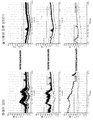
- FIG. 10 is a diagram illustrating improvement of an EMC noise of a motor according to an embodiment.
- the horizontal axis represents frequency and the vertical axis represents noise level.
- the EMS noise of the motor 1 is improved.
- the noise is reduced by 10 ⁇ 20dB.
- the first coil 410 and the second coil 420 wound on the core 300 may be disposed on the core 300 to be spaced apart from each other in the long axis direction of the core 300. Can be.
- one side of the core 300 around which the first coil 410 and the second coil 420 are wound may be disposed between the first guide protrusions 220, and the other side may be disposed between the second guide protrusions 230. Can be.
- the first guide protrusion 220 and the second guide protrusion 230 may be symmetrically disposed with respect to the second region 320 of the core 300. As shown in FIG. 5, the first guide protrusion 220 and the second guide protrusion are based on an imaginary straight line L2 connecting the center C and the center C1 with respect to the long axis direction of the core 300. 230 may be symmetrically disposed with respect to the second region 320 of the core 300.
- the core 300 wound around the first coil 410 and the second coil 420 may be coupled to the first guide protrusion 220 and the second guide protrusion 230 by a press-fit method. Accordingly, the first coil 410 wound on the core 300 may contact the inner surface 221 of the first guide protrusion 220. In addition, the second coil 420 wound on the core 300 may contact the inner surface 231 of the second guide protrusion 230.
- a part of the core 300 around which the first coil 410 and the second coil 420 are wound may be disposed in the guide groove 240.
- the brush 500 may be disposed under the cover 200.
- a plurality of brushes 500 may be disposed, and one side of each brush 500 may contact the commutator 1000. That is, when N brushes 500 are disposed on the cover 200, N / 2 cores 300 may be disposed. Where N is an integer.
- two brushes 500 share one core 300.
- two coils 400 may be disposed in one core 300.
- the brush 500 may be formed in a rectangular parallelepiped shape in one direction. Accordingly, the long axis direction of the brush 500 may be a length direction of the brush.
- the first brush 510 and the second brush 520 may be disposed to face each other based on the center C. Referring to FIG. That is, one surface in the long axis direction of the first brush 510 and one surface in the long axis direction of the second brush 520 may be spaced apart from each other to face each other.
- the first brush 510 and the second brush 520 may be disposed on the virtual straight line L1 passing through the center C in the radial direction.
- the second brush 520 is the first brush based on the center C. It corresponds to the brush 510 and is disposed on the virtual straight line L1.
- One side of the first brush 510 may be connected to one end of the first coil 410.
- One side of the second brush 512 may be connected to one end of the second coil 420.
- the first brush 510 may overlap one end of the core 300 in a direction perpendicular to the long axis of the core 300.
- the second brush 520 may be disposed to overlap the other end of the core 300 in a direction perpendicular to the long axis of the core 300.
- a portion of the first brush 510 may be disposed to overlap one end of the core 300.
- a portion of the second brush 520 may be disposed to overlap the other end of the core 300.
- a portion of the first brush 510 in the radial direction may be disposed to overlap with a portion of the first coil 410.
- the second brush 520 may be disposed to overlap a part of the second coil 420.
- the motor 1 may include a brush holder 530.
- the brush holder 530 may be disposed to cover each of the brushes 500.
- the brush holder 530 may be disposed on the cover 200 to cover each of the first brush 510 and the second brush 520.
- an elastic member 540 such as a spring is disposed inside the brush holder 530 to press one side of the brush 500. Accordingly, the other side of the brush 500 is in contact with the commutator 1000.
- the elastic member 540 may be disposed to press each of the first brush 510 and the second brush 520 using an elastic force.
- the terminal 600 may be disposed under the cover 200. In this case, a plurality of terminals 600 may be disposed.
- the terminal 600 may include a first terminal 610 and a second terminal 620.
- the first terminal 610 may be electrically connected to one side of the first coil 410. Accordingly, one side of the first coil 410 is connected to the first terminal 610, and the other side of the first coil 410 is connected to the first brush 510.
- the first terminal 610 may include a groove 611. Accordingly, one side of the first coil 410 may be disposed in the groove 611 of the first terminal 610.
- the groove 611 formed in the first terminal 610 may be referred to as a first groove.
- the second terminal 620 may be electrically connected to one side of the second coil 420. Accordingly, one side of the second coil 420 is connected to the second terminal 620, and the other side of the second coil 420 is connected to the second brush 520.
- the second terminal 620 may include a groove 621. Accordingly, one side of the first coil 410 may be disposed in the groove 621 of the second terminal 620.
- the groove 621 formed in the second terminal 620 may be referred to as a second groove.
- the distance from the center C of the cover 200 to the second terminal 620 may be greater than the distance from the center C of the cover 200 to the first terminal 610.
- the first terminal 610 and the second terminal 620 may be disposed to overlap the second region 320 of the core 300 in a direction perpendicular to the shaft 900.
- the first terminal 610 and the second terminal 620 may be disposed to overlap the second area 320 of the core 300.
- poles of the power applied to the first terminal 610 and the second terminal 620 may be different from each other.
- a '+' pole may be connected to the first terminal 610
- a ' ⁇ ' pole may be connected to the second terminal 620.
- the stator 700 induces electrical interaction with the rotor 800 to induce rotation of the rotor 800.
- the stator 700 is coupled to the inside of the housing 100, and the stator 700 may include a plurality of magnets.
- the magnet forms a rotating magnetic field with a coil wound on the rotor 800.
- the magnet may be arranged such that the north pole and the south pole are alternately positioned along the circumferential direction with respect to the center (C).
- the stator 700 may include a stator core for placement of the magnet, but is not limited thereto.
- the stator core may be manufactured by combining a plurality of split cores or may be manufactured in the form of a single core composed of one cylinder.
- the rotor 800 is disposed inside the stator 700. That is, the stator 700 may be disposed outside the rotor 800.
- the rotor 800 may include a rotor core and a coil.
- the rotor core may be formed of a plurality of plates stacked in the form of a thin steel sheet, but is not necessarily limited thereto.
- the rotor core may be formed in one single piece.
- a plurality of teeth may protrude from the outer circumferential surface of the rotor core.
- the tooth may be disposed to protrude in a radial direction with respect to the center of the rotor 800.
- the tooth may be arranged to face the magnet.
- a coil is wound around each tooth.
- the insulator may be installed in the tooth. The insulator insulates the stator core from the coil.
- the shaft 900 When the current is supplied to the coil, electrical interaction with the magnet may be induced, such that the rotor 800 may rotate.
- the shaft 900 When the rotor 800 rotates, the shaft 900 also rotates.
- the shaft 900 may be supported by the bearing 10 disposed on the upper side and the lower side.
- the commutator 1000 couples to the shaft 900.
- the commutator 1000 may be disposed above the rotor 800.
- the commutator 1000 may be disposed between the cover 200 and the rotor 800.
- the commutator 1000 is electrically connected to the coil of the rotor 800.
- Reference Signs List 1 motor 100 housing, 200 cover, 210 cover body, 220 first guide protrusion, 230 second guide protrusion, 300 core, 310 first region, 311 first surface, 320 first 2 regions, 330: third region, 331: second surface, 400: coil, 410: first coil, 420: second coil, 500: brush, 510: first brush, 520: second brush, 600: terminal 610: first terminal, 620: second terminal, 700: stator, 800: rotor, 900: shaft, 1000: commutator
Landscapes
- Engineering & Computer Science (AREA)
- Power Engineering (AREA)
- Physics & Mathematics (AREA)
- Electromagnetism (AREA)
- Microelectronics & Electronic Packaging (AREA)
- Motor Or Generator Frames (AREA)
Abstract
실시예는 하우징; 상기 하우징 내에 배치되는 스테이터; 상기 스테이터 내에 배치되는 로터; 상기 로터와 결합하는 샤프트; 상기 하우징 상에 배치되는 커버; 상기 커버에 배치되는 코어; 상기 코어와 전기적으로 연결되는 복수 개의 브러시; 및 상기 코어에 권선되는 복수 개의 코일을 포함하고, 상기 코어는 제1 영역, 상기 제1 영역과 연결되고 중심을 포함하는 제2 영역 및 상기 제2 영역과 연결되는 제3 영역을 포함하며, 상기 코일은 상기 코어의 제1 영역에 권선되는 제1 코일과 상기 코어의 제3 영역에 권선되는 제2 코일을 포함하고, 상기 코어의 제2 영역을 기준으로 상기 제1 코일의 권선 방향과 상기 제2 코일의 권선 방향은 서로 동일한 모터에 관한 것이다. 이에 따라, 상기 모터는 단일 코어에 권선되는 두 개의 코일을 이용하여 외부에서 발생한 전자파에 영향을 방지 또는 최소화할 수 있다.
Description
실시예는 모터에 관한 것이다.
일반적으로 모터는 회전 가능하게 배치되는 샤프트, 샤프트와 결합되는 로터, 하우징 내측에 고정되는 스테이터가 마련되는데, 로터의 둘레를 따라 간극을 두고 스테이터가 설치된다.
상기 모터는 전기적 상호 작용으로 로터의 회전을 유도한다. 로터에 코일이 감긴 경우, 회전하는 로터에 감긴 코일에 전류를 공급하기 위하여 상기 모터는 정류자와 브러시(brush)를 포함할 수 있다.
통상적으로, 상기 정류자는 코일과 연결된 상태로 샤프트에 결합하여 상기 샤프트와 함께 회전한다. 그리고, 상기 브러시는 정류자와 접촉 가능하게 커버에 배치된다. 그에 따라 상기 브러시는 정류자에 전기를 공급한다.
상기 모터가 차량에 설치되는 경우, 차량의 전자 부품과 상기 모터 간에 전자파 간섭 문제가 발생할 수 있다.
그에 따라, 상기 모터에는 전자파 노이즈 필터의 기능을 수행하도록 상기 브러시와 전기적으로 연결되는 쵸크 코일이 필수적으로 배치된다.
이때, 상기 쵸크 코일은 제한된 모터 내부의 공간에 배치되면서도 노이즈를 최소화해야 하기 때문에, 높은 인덕턴스를 갖는 것이 중요하다. 여기서, 상기 인덕턴스는 쵸크 코일의 턴수에 비례한다.
따라서, 쵸크 코일의 턴수를 향상시킬 수 있는 모터가 요구되고 있는 실정이다.
실시예는 전자파 간섭 문제를 방지하도록 쵸크 코일의 턴수를 향상시키게 설계된 모터를 제공한다.
본 발명이 해결하고자 하는 과제는 이상에서 언급된 과제에 국한되지 않으며 여기서 언급되지 않은 또 다른 과제들은 아래의 기재로부터 당업자에게 명확하게 이해될 수 있을 것이다.
상기 과제는 실시예에 따라, 하우징; 상기 하우징 내에 배치되는 스테이터; 상기 스테이터 내에 배치되는 로터; 상기 로터와 결합하는 샤프트; 상기 하우징 상에 배치되는 커버; 상기 커버에 배치되는 코어; 상기 코어와 전기적으로 연결되는 복수 개의 브러시; 및 상기 코어에 권선되는 복수 개의 코일을 포함하고, 상기 코어는 제1 영역, 상기 제1 영역과 연결되고 중심을 포함하는 제2 영역 및 상기 제2 영역과 연결되는 제3 영역을 포함하며, 상기 코일은 상기 코어의 제1 영역에 권선되는 제1 코일과 상기 코어의 제3 영역에 권선되는 제2 코일을 포함하고, 상기 코어의 제2 영역을 기준으로 상기 제1 코일의 권선 방향과 상기 제2 코일의 권선 방향은 서로 동일한 모터에 의해 달성된다.
여기서, 상기 코어의 장축 길이는 상기 브러시 각각의 장축 길이의 합보다 길 수 있다.
그리고, 상기 코어의 장축 길이는 상기 커버의 반지름보다 길 수 있다.
또한, 상기 코어의 제2 영역은 상기 코일이 권선되지 않는 영역일 수 있다.
또한, 상기 모터는 상기 커버에 배치되는 제1 단자와 제2 단자를 더 포함하고, 복수 개의 상기 브러시는 제1 브러시와 제2 브러시를 포함하고, 상기 제1 코일의 일측은 상기 제1 단자에 연결되고, 상기 제1 코일의 타측은 상기 제1 브러시에 연결되며, 상기 제2 코일의 일측은 상기 제2 단자에 연결되고, 상기 제2 코일의 타측은 상기 제2 브러시에 연결될 수 있다.
여기서, 상기 제1 단자와 상기 제2 단자는 상기 샤프트와 수직한 방향으로 상기 제2 영역과 중첩될 수 있다.
또한, 상기 제1 단자 및 상기 제2 단자 각각은 홈을 포함하고, 상기 제1 코일의 일측은 상기 제1 단자의 홈 내에 배치되고, 상기 제2 코일의 일측은 상기 제2 단자의 홈 내에 배치될 수 있다.
그리고, 상기 제1 단자 및 상기 제2 단자에 각각 인가되는 전원의 극은 서로 상이할 수 있다.
또한, 상기 커버의 중심에서 상기 제2 단자까지의 거리는 상기 커버의 중심에서 상기 제1 단자까지의 거리보다 클 수 있다.
또한, 상기 제1 브러시는 상기 커버의 중심을 지나는 가상의 직선 상에 배치되고, 상기 제2 브러시는 상기 중심을 기준으로 상기 제1 브러시와 대응되고, 가상의 상기 직선 상에 배치될 수 있다.
여기서, 상기 코어의 장축 방향은 가상의 상기 직선과 서로 평행일 수 있다.
한편, 상기 커버는 상기 코어의 제1 영역에 인접한 제1 가이드 돌기와 상기 코어의 제3 영역에 인접한 제2 가이드 돌기를 포함하고, 상기 제1 가이드 돌기와 상기 제2 가이드 돌기는 상기 코어의 제2 영역을 기준으로 대칭일 수 있다.
또한, 상기 브러시는 N개이고, 상기 코어는 N/2개일 수 있다. 여기서, N은 정수이다.
또한, 상기 코어는 원기둥 형상으로 형성될 수 있다.
여기서, 상기 코어는 일 끝단에 배치된 원형의 제1 면과 상기 제1 면과 대향하여 상기 코어의 타 끝단에 배치된 원형의 제2 면을 포함하고, 상기 제1 영역은 상기 제1 면을 포함하고, 상기 제3 영역은 상기 제2 면을 포함할 수 있다.
상기 과제는 실시예에 따라, 스테이터; 상기 스테이터 내에 배치되는 로터; 상기 로터와 결합하는 샤프트; 상기 로터 상에 배치되는 커버; 상기 커버와 결합되는 코어; 상기 코어와 전기적으로 연결되는 브러시; 및 상기 코어에 배치되는 코일을 포함하고, 상기 코어는 장축을 갖는 단일 코어이고, 상기 코일은 상기 단일 코어의 일측에 배치된 제1 코일과 상기 제1 코일과 분리되고 상기 단일 코어의 타측에 배치된 제2 코일을 포함하고, 상기 제1 코일의 자기장 방향과 상기 제2 코일의 자기장 방향은 동일한 모터에 의해 달성된다.
여기서, 상기 단일 코어의 장축 길이는 상기 커버의 반지름보다 크고, 상기 브러시는 제1 코일과 전기적으로 연결되는 제1 브러시와 상기 제2 코일과 전기적으로 연결되는 제2 브러시를 포함하고, 상기 제1 브러시는 상기 코어의 일측 끝단과 상기 코어의 장축과 수직한 방향으로 중첩되고, 상기 제2 브러시는 상기 코어의 타측 끝단과 상기 코어의 장축과 수직한 방향으로 중첩될 수 있다.
또한, 상기 제1 코일의 권선 수는 11~14턴의 권선수를 가질 수 있다.
실시예에 따른 모터는 단일 코어에 권선되는 두 개의 코일을 이용하여 외부에서 발생한 전자파에 영향을 방지 또는 최소화할 수 있다. 예컨데, 상기 모터는 커버의 사이즈 증가없이 단일 코어를 이용하여 상기 코어에 권선되는 코일의 권선 수를 향상시킬 수 있다. 그에 따라, 상기 모터는 외부에서 발생한 전자파에 의한 간섭을 방지 또는 최소화할 수 있다.
실시예의 다양하면서도 유익한 장점과 효과는 상술한 내용에 한정되지 않으며, 실시예의 구체적인 실시형태를 설명하는 과정에서 보다 쉽게 이해될 수 있을 것이다.
도 1은 실시예에 따른 모터를 나타내는 사시도이고,
도 2는 실시예에 따른 모터를 나타내는 단면도이고,
도 3은 실시예에 따른 모터의 커버에 대한 코어, 코일, 브러시 및 단자의 배치를 나타내는 저면사시도이고,
도 4는 실시예에 따른 모터의 커버에 대한 코어, 코일, 브러시 및 단자의 배치를 나타내는 분해사시도이고,
도 5는 실시예에 따른 모터의 커버에 대한 코어, 코일, 브러시 및 단자의 배치를 나타내는 저면도이고,
도 6은 실시예에 따른 모터의 커버에 대한 코어, 코일, 브러시 및 단자의 배치를 나타내는 정면도이고,
도 7은 실시예에 따른 모터의 커버를 나타내는 저면도이고,
도 8은 실시예에 따른 모터의 커버를 나타내는 단면도이고,
도 9는 실시예에 따른 모터의 인덕턴스 및 임피던스의 개선을 나타내는 도면이고,
도 10은 실시예에 따른 모터의 이엠씨(EMC) 노이즈의 개선을 나타내는 도면이다.
이하, 첨부된 도면을 참조하여 본 발명의 바람직한 실시예를 상세히 설명한다.
다만, 본 발명의 기술 사상은 설명되는 일부 실시 예에 한정되는 것이 아니라 서로 다른 다양한 형태로 구현될 수 있고, 본 발명의 기술 사상 범위 내에서라면, 실시 예들간 그 구성 요소들 중 하나 이상을 선택적으로 결합, 치환하여 사용할 수 있다.
또한, 본 발명의 실시예에서 사용되는 용어(기술 및 과학적 용어를 포함)는, 명백하게 특별히 정의되어 기술되지 않는 한, 본 발명이 속하는 기술분야에서 통상의 지식을 가진 자에게 일반적으로 이해될 수 있는 의미로 해석될 수 있으며, 사전에 정의된 용어와 같이 일반적으로 사용되는 용어들은 관련 기술의 문맥상의 의미를 고려하여 그 의미를 해석할 수 있을 것이다.
또한, 본 발명의 실시예에서 사용된 용어는 실시예들을 설명하기 위한 것이며 본 발명을 제한하고자 하는 것은 아니다.
본 명세서에서, 단수형은 문구에서 특별히 언급하지 않는 한 복수형도 포함할 수 있고, "A 및(와) B, C 중 적어도 하나(또는 한 개 이상)"로 기재되는 경우 A, B, C로 조합할 수 있는 모든 조합 중 하나 이상을 포함할 수 있다.
또한, 본 발명의 실시 예의 구성 요소를 설명하는 데 있어서, 제1, 제2, A, B, (a), (b) 등의 용어를 사용할 수 있다.
이러한 용어는 그 구성 요소를 다른 구성 요소와 구별하기 위한 것일 뿐, 그 용어에 의해 해당 구성 요소의 본질이나 차례 또는 순서 등으로 한정되지 않는다.
그리고, 어떤 구성 요소가 다른 구성요소에 '연결', '결합' 또는 '접속'된다고 기재된 경우, 그 구성 요소는 그 다른 구성 요소에 직접적으로 연결, 결합 또는 접속되는 경우뿐만 아니라, 그 구성 요소와 그 다른 구성 요소 사이에 있는 또 다른 구성 요소로 인해 '연결', '결합' 또는 '접속'되는 경우도 포함할 수 있다.
또한, 각 구성 요소의 "상(위) 또는 하(아래)"에 형성 또는 배치되는 것으로 기재되는 경우, 상(위) 또는 하(아래)는 두 개의 구성 요소들이 서로 직접 접촉되는 경우뿐만 아니라 하나 이상의 또 다른 구성 요소가 두 개의 구성 요소들 사이에 형성 또는 배치되는 경우도 포함한다. 또한, "상(위) 또는 하(아래)"로 표현되는 경우 하나의 구성 요소를 기준으로 위쪽 방향뿐만 아니라 아래쪽 방향의 의미도 포함할 수 있다.
이하, 첨부된 도면을 참조하여 실시예를 상세히 설명하되, 도면 부호에 관계없이 동일하거나 대응하는 구성 요소는 동일한 참조 번호를 부여하고 이에 대한 중복되는 설명은 생략하기로 한다.
도 1은 실시예에 따른 모터를 나타내는 사시도이고, 도 2는 실시예에 따른 모터를 나타내는 단면도이고, 도 3은 실시예에 따른 모터의 커버에 대한 코어, 코일, 브러시 및 단자의 배치를 나타내는 저면사시도이고, 도 4는 실시예에 따른 모터의 커버에 대한 코어, 코일, 브러시 및 단자의 배치를 나타내는 분해사시도이고, 도 5는 실시예에 따른 모터의 커버에 대한 코어, 코일, 브러시 및 단자의 배치를 나타내는 저면도이고, 도 6은 실시예에 따른 모터의 커버에 대한 코어, 코일, 브러시 및 단자의 배치를 나타내는 정면도이다. 여기서, 도 2는 도 1의 A-A선을 나타내는 단면도이다. 그리고, 도 2의 x 방향은 축 방향을 나타내고, y 방향은 반경 방향을 나타낸다. 이때, 상기 축 방향과 상기 반경 방향은 수직한다. 여기서, 상기 축 방향은 샤프트의 길이 방향일 수 있다. 그리고, 도면 부호 C는 상기 모터(1)의 중심을 나타낸다.
도 1 내지 도 6을 참조하면, 실시예에 따른 모터(1)는 하우징(100), 하우징(100) 상에 배치되는 커버(200), 커버(200)에 배치되는 코어(300), 코어(300)에 권선되는 복수 개의 코일(400), 코어(300)와 전기적으로 연결되는 복수 개의 브러시(500), 커버(200)에 배치되며 코일(400)의 일측과 전기적으로 연결되는 복수 개의 단자(600), 하우징(100) 내에 배치되는 스테이터(700), 스테이터(700) 내측에 배치되는 로터(800), 로터(800)와 결합하는 샤프트(900) 및 샤프트(900)와 결합하는 정류자(1000)를 포함할 수 있다. 여기서, 상기 내측이라 함은 반경 방향을 기준으로 상기 모터(1)의 중심(C)을 향하여 배치되는 방향을 의미하고, 외측이라 함은 상기 내측과 반대되는 방향을 의미한다.
한편, 상기 모터(1)는 샤프트(900)의 외주면에 배치되는 베어링(10)을 포함할 수 있다. 여기서, 베어링(10)은 샤프트(900)의 상부와 하부에 각각 배치되어 샤프트(900)를 회전 가능하게 한다.
이러한, 상기 모터(1)는 EPS에 사용되는 모터일 수 있다. 상기 EPS(Electronic Power Steering System)란, 모터의 구동력으로 조향력을 보조함으로써, 선회 안정성을 보장하고 신속한 복원력을 제공하여 운전자로 하여금 안전한 주행이 가능하도록 한다. 또는, 상기 모터(1)는 ABS(Anti-lock Brake System)에 사용되는 모터일 수 있다. 즉, 상기 모터(1)는 샤프트(900)가 차량의 제동장치와 연결되어 제동력을 조절하기 위한 동력을 전달하도록 하여, 차량의 주행 중에 브레이크 페달 가압 시 발생하는 조향 불안전성의 문제를 해결할 수 있다.
하우징(100), 커버(200) 및 커버(200)의 상부에 배치되는 베어링(10)은 상기 모터(1)의 외형을 형성할 수 있다. 여기서, 상기 커버(200)는 하우징(100)의 개방된 상부를 덮도록 배치될 수 있다.
하우징(100)과 커버(200)의 결합에 의해 내부에 수용공간이 형성될 수 있다. 그리고, 상기 수용공간에는, 도 2에 도시된 바와 같이, 브러시(500), 스테이터(700), 로터(800), 샤프트(900) 및 정류자(1000) 등이 배치될 수 있다.
하우징(100)은 내부에 스테이터(700), 로터(800) 등을 수용할 수 있다. 이때, 하우징(100)의 형상이나 재질은 다양하게 변경될 수 있다. 예컨데, 하우징(100)은 고온에서도 잘 견딜 수 있는 금속 재질로 형성될 수 있다.
하우징(100)은 원통 형상으로 형성될 수 있다.
그리고, 하우징(100)의 저면에는 베어링(10)이 배치될 수 있다. 이때, 상기 베어링(10)의 배치를 위해, 하우징(100)은 저면에서 축 방향으로 돌출된 하우징 돌출부(110)를 포함할 수 있다. 그에 따라, 샤프트(900)의 하부측 외주면에 배치되는 베어링(10)의 외주면은 하우징 돌출부(110)에 의해 지지될 수 있다.
커버(200)는 상기 하우징(100)의 개구를 덮도록 하우징(100)의 개구면, 즉 하우징(100)의 상부에 배치될 수 있다. 이때, 커버(200)는 압입 방식을 통해 하우징(100)의 상부에 결합될 수 있다.
도 2를 참조하면, 커버(200)는 상부 커버(200a)와 상부 커버(200a)의 하측에 배치되는 하부 커버(200b)를 포함할 수 있다. 여기서, 상부 커버(200a)는 금속 재질로 형성될 수 있고, 하부 커버(200b)는 플라스틱과 같은 합성 수지 재질로 형성될 수 있다.
도 2에 도시된 바와 같이, 상부 커버(200a)는 가장자리가 상측으로 절곡될 수 있다. 그에 따라, 커버(200)의 가장자리를 기준으로 상부 커버(200a)의 가장자리는 하부 커버(200b)와 이격되게 배치될 수 있다.
따라서, 상부 커버(200a)와 하부 커버(200b) 사이에는 실링부재(20)가 배치될 수 있다. 이때, 실링부재(20)는 하부 커버(200b)의 상측 가장자리에 배치될 수 있다. 그리고, 실링부재(20)는 하우징(100)의 내주면에 접촉될 수 있다.
따라서, 상기 모터(1)는 상부 커버(200a)와 하부 커버(200b) 사이에 배치되는 실링부재(20)를 포함할 수 있다.
여기서, 실링부재(20)는 고무와 같은 재질로 형성될 수 있으며, 'X'자 형상의 단면 또는 'D'자 형상의 단면을 갖도록 형성될 수 있다. 상기 실링부재(20)가 'X'자 형상의 단면인 경우, 'X'자를 형성하는 꼭지점들은 상부 커버(200a) 및 하우징(100)의 내주면과 접촉한다. 또한, 실링부재(20)를 'D'자 형상으로 하는 경우 곡률을 포함하고 있는 부분은 상부 커버(200a)와 접촉하도록 배치하고 그 외의 부분을 하우징(100)의 내주면과 접촉하도록 배치하면 이물질 유입 방지 효과를 더욱 향상시킬 수 있다. 하지만, 실링부재(20)의 형상은 'X'자 형상의 단면 또는 'D'자 형상의 단면에 한정되지 않는다. 예컨데, 실링부재(20)로 오링이 배치될 수도 있다.
따라서, 상기 실링부재(20)는 상기 모터(1) 내부로 물과 같은 액체가 유입되는 것을 방지한다.
상술 된 바와 같이, 커버(200)는 상부 커버(200a)와 하부 커버(200b)로 구분된 것을 그 예로 하고 있으나 반드시 이에 한정되지 않는다. 예컨데, 커버(200)는 단일품으로 제공될 수도 있다.
또한, 커버(200)는 샤프트(900)의 배치를 위해 중앙에 홀이 형성될 수 있다. 이때, 샤프트(900)는 상기 홀에 압입 방식으로 결합될 수 있다.
도 7은 실시예에 따른 모터의 커버를 나타내는 저면도이고, 도 8은 실시예에 따른 모터의 커버를 나타내는 단면도이다. 여기서, 도 8은 도 7의 B-B선을 나타내는 단면도이다.
도 7을 참조하면, 커버(200)는 커버 바디(210), 커버 바디(210)의 하면(211)에서 축 방향으로 돌출된 제1 가이드 돌기(220) 및 커버 바디(210)의 하면에서 축 방향으로 돌출된 제2 가이드 돌기(230)를 포함할 수 있다. 여기서, 커버 바디(210), 제1 가이드 돌기(220) 및 제2 가이드 돌기(230)는 일체로 형성될 수 있다.
커버 바디(210)는 상기 하우징(100)의 개구를 덮도록 하우징(100)의 개구면, 즉 하우징(100)의 상부에 배치될 수 있다.
커버 바디(210)는 소정의 반지름(R1)을 갖는 원판 형상으로 형성될 수 있다. 이때, 커버 바디(210)의 반지름(R1)은 커버(200)의 반지름일 수 있다.
도 7에 도시된 바와 같이, 제1 가이드 돌기(220)는 서로 마주보게 두 개가 배치될 수 있다. 또한, 제2 가이드 돌기(230)는 서로 마주보게 두 개가 배치될 수 있다. 그에 따라, 제1 가이드 돌기(220)와 제2 가이드 돌기(230)는 코일(400)이 권선된 코어(300)의 배치를 안내할 수 있다.
한편, 커버(200)는 제1 가이드 돌기(220)의 사이 및 제2 가이드 돌기(230)의 사이에 오목하게 형성된 가이드 홈(240)을 포함할 수 있다. 예컨데, 상기 가이드 홈(240)은 커버 바디(210)의 하면(211)에 오목하게 형성될 수 있다. 이때, 가이드 홈(240)은 코어(300)의 장축 방향과 동일한 방향으로 길게 형성될 수 있다.
그에 따라, 상기 가이드 홈(240)은 코일(400)이 권선된 코어(300)의 배치를 안내할 수 있다.
또한, 상기 커버(200)는 외주면에서 내측으로 오목하게 형성된 제1 홈(250)을 포함할 수 있다. 그리고, 상기 제1 홈(250)에는 실링부재(20)가 배치될 수 있다.
또한, 상기 커버(200)는 상면에서 축 방향으로 돌출된 돌출부(260)를 포함할 수 있다. 그리고, 돌출부(260)의 내측에는 베어링(10)이 배치될 수 있다. 도 2에 도시된 바와 같이, 돌출부(260)와 샤프트(900) 사이에는 베어링(10)이 배치되기 때문에, 샤프트(900)는 커버(200)에 대해 회전 가능하게 배치될 수 있다.
돌출부(260)는 상기 홀의 외측에 인접하게 배치될 수 있다. 그리고, 상기 돌출부(260)의 내경은 상기 홀의 내경보다 클 수 있다.
코어(300)는 커버(200)의 하부에 배치될 수 있다.
코어(300)는 장축을 갖는 단일 코어일 수 있다. 도 4에 도시된 바와 같이, 코어(300)는 원기둥 형상으로 형성될 수 있다. 그에 따라, 코어(300)의 장축 방향은 코어(300)의 길이 방향일 수 있다. 여기서, 코어(300)는 페라이트 재질로 형성될 수 있다.
도 4를 참조하면, 코어(300)는 코일(400)의 권선에 따라 제1 영역(310), 제1 영역(310)과 연결되고 중심(C1)을 포함하는 제2 영역(320) 및 제2 영역(320)과 연결되는 제3 영역(330)을 포함할 수 있다. 이때, 코어(300)의 제1 영역(310)에는 제1 코일(410)이 권선되고, 코어(300)의 제3 영역(330)에는 제2 코일(420)이 권선될 수 있다. 여기서, 제2 영역(320)은 코일(400)이 권선되지 않는 영역이다. 그리고, 상기 중심(C1)은 코어(300)의 장축 방향에 대한 길이의 중심일 수 있다.
코어(300)는 일 끝단에 배치된 원형의 제1 면(311)과, 제1 면(311)과 대향하여 코어(300)의 타 끝단에 배치된 원형의 제2 면(331)을 포함할 수 있다. 이때, 제1 영역(310)은 제1 면(311)을 포함하고, 제3 영역(330)은 제2 면(331)을 포함할 수 있다. 즉, 코어(300)는 장축 방향을 기준으로 반대 방향에 배치되는 제1 면(311)과 제2 면(331)을 포함할 수 있다.
도 4를 참조하면, 코어(300)의 장축 길이(D2)는 상기 브러시(500) 각각의 장축 길이(D1)의 합보다 길 수 있다.
도 5를 참조하면, 코어(300)의 장축 길이(D2)는 커버(200)의 반지름(R1)보다 길 수 있다.
또한, 도 5에 도시된 바와 같이, 커버(200)의 중심(C)과 서로 마주보게 배치되는 브러시(500) 각각의 중심을 지나는 가상의 직선(L1)이 형성될 수 있다. 그리고, 상기 직선(L1)은 커버(200)의 중심(C)을 지날 수 있다. 이때, 코어(300)의 장축 방향은 가상의 상기 직선(L1)과 평행하게 배치될 수 있다.
즉, 코어(300)의 장축 방향은 상기 브러시(500)의 장축 방향(길이 방향)과 평행하게 배치될 수 있다.
코일(400)은 코어(300)에 권선될 수 있다.
코일(400)은 코어(300)의 제1 영역(310)에 권선되는 제1 코일(410) 및 코어(300)의 제3 영역(330)에 권선되는 제2 코일(420)을 포함할 수 있다. 이때, 코어(300)의 제2 영역(320)을 기준으로 상기 제1 코일(410)의 권선 방향과 상기 제2 코일(420)의 권선 방향은 서로 동일할 수 있다.
즉, 코일(400)은 상기 단일 코어의 일측에 배치된 제1 코일(410)과 상기 제1 코일(410)과 분리되고 상기 단일 코어의 타측에 배치된 제2 코일(420)을 포함할 수 있다. 이때, 제1 코일(410) 및 제2 코일(420) 각각에 인가되는 전원에 의해 제1 코일(410) 및 제2 코일(420) 각각에 형성되는 자기장 간의 간섭을 고려하여, 상기 제1 코일(410)의 자기장 방향과 상기 제2 코일(420)의 자기장 방향은 동일할 수 있다.
두 개의 코어에 코일이 각각 권선되는 종래의 경우보다, 실시예에 따른 모터(1)는 코일(400) 당 2~3턴의 권선수를 더 가질 수 있다. 예컨데, 제1 코일(410) 및 제2 코일(420) 각각마다 2~3턴의 권선수를 더 가질 수 있다. 따라서, 코일(400)은 코어(300)에 대해 총 4~6턴의 권선수를 더 가질 수 있다.
제1 코일(410)의 권선 수는 코어(300)에 대한 11~14턴의 권선수를 가질 수 있다. 그리고, 제2 코일(420)의 권선 수는 코어(300)에 대한 11~14턴의 권선수를 가질 수 있다.
따라서, 인덕턴스는 코일(400)의 턴수의 제곱에 비례하기 때문에, 상기 모터(1)는 코일(400)의 권선 수 증가로 인해 인덕턴스가 개선된다. 예컨데, 코어(300)의 직경이 6.0mm이고 길이가 19mm이며, 코일(400)의 선경이 1.5mm일 때, 종래의 두 개의 코어 각각에 권선되는 코일보다 약 27~64% 정도 인덕턴스가 개선된다.
도 9는 실시예에 따른 모터의 인덕턴스 및 임피던스의 개선을 나타내는 도면이다.
도 9에 도시된 바와 같이, 상기 모터(1)의 제1 코일(410) 및 제2 코일(420) 각각마다 2~3턴의 권선수를 갖도록 권선되기 때문에, 인덕턴스(Inductance) 및 임피던스(Impedance)가 개선됨을 확인할 수 있다. 특히, 상기 모터(1)는 인덕턴스가 2.5~5μΗ 정도 개선된다.
여기서, 상기 모터(1)에 대한 비교예로 제공되는 두 개의 코어에 각각 권선되는 코일을 포함하는 종래의 모터의 경우, 각각의 코어에 권선되는 코일은 10.5턴의 권선수를 갖으며, 그에 따라, 종래의 모터에서 제공되는 인덕턴스는 2.2μΗ이다.
도 10은 실시예에 따른 모터의 이엠씨(EMC) 노이즈의 개선을 나타내는 도면이다. 도 10에 있어서, 수평축은 주파수를 나타내고, 수직축은 노이즈 레벨을 나타낸다.
도 10을 참조하면, 상기 모터(1)의 이엠씨(EMC) 노이즈의 개선됨을 확인할 수 있다. 예컨데, 30~300MHz의 대역에서 상기 노이즈는 10~20dB 감소됨을 확인할 수 있다.
도 3 및 도 5에 도시된 바와 같이, 코어(300)에 권선된 제1 코일(410)과 제2 코일(420)은 코어(300)의 장축 방향으로 서로 이격되게 코어(300)에 배치될 수 있다.
그리고, 제1 코일(410)과 제2 코일(420)이 권선된 코어(300)의 일측은 제1 가이드 돌기(220) 사이에 배치되고, 타측은 제2 가이드 돌기(230) 사이에 배치될 수 있다.
도 5를 참조하면, 제1 가이드 돌기(220)와 상기 제2 가이드 돌기(230)는 상기 코어(300)의 제2 영역(320)을 기준으로 대칭되게 배치될 수 있다. 도 5에 도시된 바와 같이, 중심(C)과 코어(300)의 장축 방향에 대한 중심(C1)을 잇는 가상의 직선(L2)을 기준으로 제1 가이드 돌기(220)와 상기 제2 가이드 돌기(230)는 상기 코어(300)의 제2 영역(320)을 기준으로 대칭되게 배치될 수 있다.
제1 코일(410)과 제2 코일(420)이 권선된 코어(300)는 제1 가이드 돌기(220) 및 제2 가이드 돌기(230)에 압입 방식으로 결합될 수 있다. 그에 따라, 코어(300)에 권선된 제1 코일(410)은 제1 가이드 돌기(220)의 내면(221)과 접촉될 수 있다. 그리고, 코어(300)에 권선된 제2 코일(420)은 제2 가이드 돌기(230)의 내면(231)과 접촉될 수 있다.
이때, 가이드 홈(240)에는 제1 코일(410)과 제2 코일(420)이 권선된 코어(300)의 일부가 배치될 수 있다.
브러시(500)는 커버(200)의 하부에 배치될 수 있다. 이때, 브러시(500)는 복수 개가 배치될 수 있으며, 각각의 브러시(500)의 일측은 정류자(1000)에 접촉될 수 있다. 즉, 커버(200)에 브러시(500)가 N개 배치되는 경우, 코어(300)는 N/2개가 배치될 수 있다. 여기서, N은 정수이다.
예컨데, 하나의 코어(300)를 두 개의 브러시(500)가 공유한다. 그에 따라, 하나의 코어(300)에는 두 개의 코일(400)이 배치될 수 있다.
브러시(500)는 일 방향을 긴 직육면체 형상으로 형성될 수 있다. 그에 따라, 브러시(500)의 장축 방향은 브러시의 길이 방향일 수 있다.
도 3 내지 도 5를 참조하면, 중심(C)을 기준으로 제1 브러시(510)와 제2 브러시(520)는 서로 마주보게 배치될 수 있다. 즉, 제1 브러시(510)의 장축 방향의 일면과 제2 브러시(520)의 장축 방향의 일면은 서로 마주보게 이격되어 배치될 수 있다.
여기서, 제1 브러시(510)와 제2 브러시(520)는 중심(C)을 반경 방향으로 지나는 가상의 직선(L1) 상에 배치될 수 있다. 예컨데, 제1 브러시(510)가 커버(200)의 중심(C)을 지나는 가상의 직선(L1) 상에 배치될 때, 제2 브러시(520)는 상기 중심(C)을 기준으로 상기 제1 브러시(510)와 대응되고, 가상의 상기 직선(L1) 상에 배치된다.
제1 브러시(510)의 일측은 제1 코일(410)의 일측 단부와 연결될 수 있다. 그리고, 제2 브러시(512)의 일측은 제2 코일(420)의 일측 단부와 연결될 수 있다.
도 6을 참조하면, 제1 브러시(510)는 상기 코어(300)의 일측 끝단과 상기 코어(300)의 장축과 수직한 방향으로 중첩될 수 있다. 그리고, 제2 브러시(520)는 상기 코어(300)의 타측 끝단과 상기 코어(300)의 장축과 수직한 방향으로 중첩되게 배치될 수 있다. 상기 반경 방향에서 바라볼 때, 제1 브러시(510)의 일부는 코어(300)의 일측 끝단과 오버랩되게 배치될 수 있다. 그리고, 제2 브러시(520)의 일부는 코어(300)의 타측 끝단과 오버랩되게 배치될 수 있다.
따라서, 반경 방향으로 제1 브러시(510)의 일부는 제1 코일(410)의 일부와 오버랩되게 배치될 수 있다. 그리고, 반경 방향으로 제2 브러시(520)는 제2 코일(420)의 일부와 오버랩되게 배치될 수 있다.
한편, 상기 모터(1)는 브러시 홀더(530)를 포함할 수 있다. 이때, 상기 브러시 홀더(530)는 브러시(500) 각각을 덮도록 배치될 수 있다. 예컨데, 제1 브러시(510)와 제2 브러시(520) 각각을 덮도록 브러시 홀더(530)가 커버(200)에 배치될 수 있다.
그리고, 브러시 홀더(530)의 내부에는 스프링과 같은 탄성부재(540)가 배치되어 브러시(500)의 일측을 가압한다. 그에 따라, 브러시(500)의 타측은 정류자(1000)에 접촉된다. 예컨데, 제1 브러시(510)와 제2 브러시(520) 각각을 탄성력을 이용해 가압하도록 탄성부재(540)가 배치될 수 있다.
단자(600)는 커버(200)의 하부에 배치될 수 있다. 이때, 단자(600)는 복수 개가 배치될 수 있다.
도 3을 참조하면, 단자(600)는 제1 단자(610)와 제2 단자(620)를 포함할 수 있다.
제1 단자(610)는 제1 코일(410)의 일측과 전기적으로 연결될 수 있다. 따라서, 제1 코일(410)의 일측은 제1 단자(610)에 연결되고, 제1 코일(410)의 타측은 제1 브러시(510)에 연결된다. 이때, 제1 단자(610)는 홈(611)을 포함할 수 있다. 그에 따라, 제1 코일(410)의 일측은 제1 단자(610)의 홈(611) 내에 배치될 수 있다. 여기서, 제1 단자(610)에 형성된 홈(611)은 제1 홈이라 불릴 수 있다.
제2 단자(620)는 제2 코일(420)의 일측과 전기적으로 연결될 수 있다. 따라서, 제2 코일(420)의 일측은 제2 단자(620)에 연결되고, 제2 코일(420)의 타측은 제2 브러시(520)에 연결된다. 이때, 제2 단자(620)는 홈(621)을 포함할 수 있다. 그에 따라, 제1 코일(410)의 일측은 제2 단자(620)의 홈(621) 내에 배치될 수 있다. 여기서, 제2 단자(620)에 형성된 홈(621)은 제2 홈이라 불릴 수 있다.
도 5를 참조하면, 커버(200)의 중심(C)에서 제2 단자(620)까지의 거리는 커버(200)의 중심(C)에서 제1 단자(610)까지의 거리보다 클 수 있다.
도 6을 참조하면, 제1 단자(610)와 제2 단자(620)는 샤프트(900)와 수직한 방향으로 코어(300)의 제2 영역(320)과 중첩되게 배치될 수 있다. 상기 반경 방향에서 바라볼 때, 제1 단자(610)와 제2 단자(620)는 코어(300)의 제2 영역(320)과 오버랩되게 배치될 수 있다.
한편, 제1 단자(610) 및 제2 단자(620)에 각각 인가되는 전원의 극은 서로 상이할 수 있다. 예컨데, 제1 단자(610)에는 '+'극이 연결될 수 있고, 제2 단자(620)에는 '-'극이 연결될 수 있다.
스테이터(700)는 로터(800)와의 전기적 상호 작용을 유발하여 로터(800)의 회전을 유도한다. 스테이터(700)는 하우징(100)의 내측에 결합된다, 그리고 스테이터(700)는 복수 개의 마그넷을 포함할 수 있다. 상기 마그넷은 로터(800)에 감긴 코일과 회전 자계를 형성한다. 이러한 마그넷은 중심(C)을 기준으로 원주 방향을 따라 N극과 S극이 번갈아 위치하도록 배치될 수 있다.
한편, 스테이터(700)는 상기 마그넷의 배치를 위해 스테이터 코어를 포함할 수 있으나 반드시 이에 한정되지 않는다. 상기 스테이터 코어는 복수 개의 분할 코어가 결합되어 제작되거나 하나의 통으로 구성되는 단일 코어 형태로 제작될 수 있다.
로터(800)는 스테이터(700)의 내측에 배치된다. 즉, 로터(800)의 외측에는 스테이터(700)가 배치될 수 있다.
로터(800)는 로터 코어와 코일을 포함할 수 있다. 로터 코어는 얇은 강판 형태의 복수 개의 플레이트가 상호 적층된 형태로 이루어질 수 있으나 반드시 이에 한정되는 것은 아니다. 예컨데 로터 코어는 하나의 단일품으로 형성될 수도 있다.
로터 코어의 외주면에는 복수 개의 투스가 돌출되게 형성될 수 있다. 상기 투스는 로터(800)의 중심을 기준으로 반지름 방향을 향해 돌출되게 배치될 수 있다. 이때, 상기 투스는 마그넷을 대향하도록 배치될 수 있다. 그리고, 각각의 투스에는 코일이 감긴다. 이때, 투스에는 인슐레이터가 설치될 수 있다. 상기 인슐레이터는 스테이터 코어와 코일을 절연시킨다.
코일에 전류가 공급되면 마그넷과 전기적 상호작용이 유발되어 로터(800)가 회전할 수 있다. 로터(800)가 회전하는 경우 샤프트(900)도 같이 회전한다. 이때, 샤프트(900)는 상부측과 하부측에 배치되는 베어링(10)에 의해 지지될 수 있다.
정류자(1000)는 샤프트(900)에 결합한다. 그리고 정류자(1000)는 로터(800)의 상부에 배치될 수 있다. 예컨데, 정류자(1000)는 커버(200)와 로터(800) 사이에 배치될 수 있다. 그리고, 정류자(1000)는 로터(800)의 코일과 전기적으로 연결된다.
상기에서는 본 발명의 바람직한 실시예를 참조하여 설명하였지만, 해당 기술 분야의 숙련된 당업자는 하기의 특허 청구의 범위에 기재된 본 발명의 사상 및 영역으로부터 벗어나지 않는 범위 내에서 본 발명을 다양하게 수정 및 변경시킬 수 있음을 이해할 수 있을 것이다.
<부호의 설명>
1: 모터, 100: 하우징, 200: 커버, 210: 커버 바디, 220: 제1 가이드 돌기, 230: 제2 가이드 돌기, 300: 코어, 310: 제1 영역, 311: 제1 면, 320: 제2 영역, 330: 제3 영역, 331: 제2 면, 400: 코일, 410: 제1 코일,420: 제2 코일, 500: 브러시, 510: 제1 브러시, 520: 제2 브러시, 600: 단자, 610: 제1 단자, 620: 제2 단자, 700: 스테이터, 800: 로터, 900: 샤프트, 1000: 정류자
Claims (18)
- 하우징;상기 하우징 내에 배치되는 스테이터;상기 스테이터 내에 배치되는 로터;상기 로터와 결합하는 샤프트;상기 하우징 상에 배치되는 커버;상기 커버에 배치되는 코어;상기 코어와 전기적으로 연결되는 복수 개의 브러시; 및상기 코어에 권선되는 복수 개의 코일을 포함하고,상기 코어는 제1 영역, 상기 제1 영역과 연결되고 중심을 포함하는 제2 영역 및 상기 제2 영역과 연결되는 제3 영역을 포함하며,상기 복수 개의 코일은 상기 코어의 제1 영역에 권선되는 제1 코일과 상기 코어의 제3 영역에 권선되는 제2 코일을 포함하고,상기 코어의 제2 영역을 기준으로 상기 제1 코일의 권선 방향과 상기 제2 코일의 권선 방향은 서로 동일한 모터.
- 제1항에 있어서,상기 코어의 장축 길이는 상기 브러시 각각의 장축 길이의 합보다 긴 모터.
- 제2항에 있어서,상기 코어의 장축 길이는 상기 커버의 반지름보다 긴 모터.
- 제1항에 있어서,상기 코어의 제2 영역은 상기 코일이 권선되지 않는 영역인 모터.
- 제1항에 있어서,상기 커버에 배치되는 제1 단자와 제2 단자를 더 포함하고,상기 복수 개의 브러시는 제1 브러시와 제2 브러시를 포함하고,상기 제1 코일의 일측은 상기 제1 단자에 연결되고, 상기 제1 코일의 타측은 상기 제1 브러시에 연결되며,상기 제2 코일의 일측은 상기 제2 단자에 연결되고, 상기 제2 코일의 타측은 상기 제2 브러시에 연결되는 모터.
- 제5항에 있어서,상기 제1 단자와 상기 제2 단자는 상기 샤프트와 수직한 방향으로 상기 제2 영역과 중첩되는 모터.
- 제5항에 있어서,상기 제1 단자 및 상기 제2 단자 각각은 홈을 포함하고,상기 제1 코일의 일측은 상기 제1 단자의 홈 내에 배치되고, 상기 제2 코일의 일측은 상기 제2 단자의 홈 내에 배치되는 모터.
- 제7항에 있어서,상기 제1 단자 및 상기 제2 단자에 각각 인가되는 전원의 극은 서로 상이한 모터.
- 제5항에 있어서,상기 커버의 중심에서 상기 제2 단자까지의 거리는 상기 커버의 중심에서 상기 제1 단자까지의 거리보다 큰 모터.
- 제5항에 있어서,상기 제1 브러시는 상기 커버의 중심을 지나는 가상의 직선 상에 배치되고,상기 제2 브러시는 상기 중심을 기준으로 상기 제1 브러시와 대응되고, 가상의 상기 직선 상에 배치되는 모터.
- 제10항에 있어서,상기 코어의 장축 방향은 가상의 상기 직선과 서로 평행인 모터.
- 제1항에 있어서,상기 커버는 상기 코어의 제1 영역에 인접한 제1 가이드 돌기와 상기 코어의 제3 영역에 인접한 제2 가이드 돌기를 포함하고,상기 제1 가이드 돌기와 상기 제2 가이드 돌기는 상기 코어의 제2 영역을 기준으로 대칭인 모터.
- 제1항에 있어서,상기 브러시는 N개이고, 상기 코어는 N/2개인 모터.
- 제1항에 있어서,상기 코어는 원기둥 형상으로 형성되는 모터.
- 제14항에 있어서,상기 코어는 일 끝단에 배치된 원형의 제1 면과 상기 제1 면과 대향하여 상기 코어의 타 끝단에 배치된 원형의 제2 면을 포함하고,상기 제1 영역은 상기 제1 면을 포함하고,상기 제3 영역은 상기 제2 면을 포함하는 모터.
- 스테이터;상기 스테이터 내에 배치되는 로터;상기 로터와 결합하는 샤프트;상기 로터 상에 배치되는 커버;상기 커버와 결합되는 코어;상기 코어와 전기적으로 연결되는 복수 개의 브러시; 및상기 코어에 배치되는 복수 개의 코일을 포함하고,상기 코어는 장축을 갖는 단일 코어이고,상기 복수 개의 코일은 상기 단일 코어의 일측에 배치된 제1 코일과 상기 제1 코일과 분리되고 상기 단일 코어의 타측에 배치된 제2 코일을 포함하고,상기 제1 코일의 자기장 방향과 상기 제2 코일의 자기장 방향은 동일한 모터.
- 제16항에 있어서,상기 단일 코어의 장축 길이는 상기 커버의 반지름보다 크고,상기 복수 개의 브러시는 제1 코일 전기적으로 연결되는 제1 브러시와 상기 제2 코일과 전기적으로 연결되는 제2 브러시를 포함하고,상기 제1 브러시는 상기 코어의 일측 끝단과 상기 코어의 장축과 수직한 방향으로 중첩되고,상기 제2 브러시는 상기 코어의 타측 끝단과 상기 코어의 장축과 수직한 방향으로 중첩되는 모터.
- 제16항에 있어서,상기 제1 코일의 권선 수는 11~14턴의 권선수를 갖는 모터.
Priority Applications (4)
| Application Number | Priority Date | Filing Date | Title |
|---|---|---|---|
| JP2021503860A JP7385646B2 (ja) | 2018-07-26 | 2019-06-14 | モータ |
| EP19840416.2A EP3829040A4 (en) | 2018-07-26 | 2019-06-14 | ENGINE |
| CN201980049743.9A CN112514216B (zh) | 2018-07-26 | 2019-06-14 | 电机 |
| US17/256,839 US20210288562A1 (en) | 2018-07-26 | 2019-06-14 | Motor |
Applications Claiming Priority (2)
| Application Number | Priority Date | Filing Date | Title |
|---|---|---|---|
| KR10-2018-0087168 | 2018-07-26 | ||
| KR1020180087168A KR102547571B1 (ko) | 2018-07-26 | 2018-07-26 | 모터 |
Publications (1)
| Publication Number | Publication Date |
|---|---|
| WO2020022647A1 true WO2020022647A1 (ko) | 2020-01-30 |
Family
ID=69180915
Family Applications (1)
| Application Number | Title | Priority Date | Filing Date |
|---|---|---|---|
| PCT/KR2019/007181 Ceased WO2020022647A1 (ko) | 2018-07-26 | 2019-06-14 | 모터 |
Country Status (6)
| Country | Link |
|---|---|
| US (1) | US20210288562A1 (ko) |
| EP (1) | EP3829040A4 (ko) |
| JP (1) | JP7385646B2 (ko) |
| KR (1) | KR102547571B1 (ko) |
| CN (1) | CN112514216B (ko) |
| WO (1) | WO2020022647A1 (ko) |
Citations (5)
| Publication number | Priority date | Publication date | Assignee | Title |
|---|---|---|---|---|
| JPH0938378A (ja) * | 1995-07-27 | 1997-02-10 | Hitachi Ltd | 整流子モータを搭載した洗濯機 |
| US20110095630A1 (en) * | 2009-10-26 | 2011-04-28 | Jiang Zhi Qiang | End cap assembly |
| JP2015070658A (ja) * | 2013-09-27 | 2015-04-13 | 国産電機株式会社 | Dcモータ |
| KR20180027020A (ko) * | 2016-09-05 | 2018-03-14 | 엘지이노텍 주식회사 | 커버 조립체 및 이를 포함하는 모터 |
| KR20180042686A (ko) * | 2016-10-18 | 2018-04-26 | 엘지이노텍 주식회사 | 접지 단자, 커버 조립체 및 이를 포함하는 모터 |
Family Cites Families (16)
| Publication number | Priority date | Publication date | Assignee | Title |
|---|---|---|---|---|
| JPS6173566A (ja) * | 1984-09-17 | 1986-04-15 | Matsushita Electric Ind Co Ltd | 直流モ−タ |
| JPS62124292U (ko) * | 1986-01-30 | 1987-08-07 | ||
| GB2268633B (en) * | 1992-07-04 | 1996-03-06 | Delco Chassis Overseas Corp | Electrical motor with interference suppression choke |
| JPH06209542A (ja) * | 1992-09-28 | 1994-07-26 | Asmo Co Ltd | モータ用雑音防止器 |
| DE19705833A1 (de) * | 1997-02-15 | 1998-08-20 | Itt Mfg Enterprises Inc | Bürstenhalteanordnung |
| US6566782B1 (en) * | 2000-06-14 | 2003-05-20 | Black & Decker Inc. | Motor armature having distributed windings for reducing arcing |
| DE10150237A1 (de) * | 2001-10-11 | 2003-05-08 | Bosch Gmbh Robert | Vorrichtung mit einem Entstörglied zur Reduzierung einer Störleistung |
| DE102004030127A1 (de) * | 2004-06-22 | 2006-01-19 | Robert Bosch Gmbh | Vorrichtung zur Dreherkennung eines Gleichstrommotors |
| DE102006062590A1 (de) * | 2006-12-29 | 2008-07-03 | Robert Bosch Gmbh | Funkentstörung für einen elektrischen Antrieb |
| JP2009273228A (ja) * | 2008-05-07 | 2009-11-19 | Panasonic Corp | 電源装置およびそれを備えた空気調和機 |
| JP2010187460A (ja) | 2009-02-12 | 2010-08-26 | Nippon Densan Corp | サーボユニット |
| DE202011050665U1 (de) * | 2011-07-07 | 2012-10-09 | Alpitronic Gmbh | Kommutierungsschaltung und elektrischer Energiewandler |
| CN102539288B (zh) * | 2012-01-19 | 2014-07-23 | 中国矿业大学 | 一种双线圈式磁流变液流变特性测试装置 |
| DE102012010483A1 (de) * | 2012-05-26 | 2013-11-28 | Brose Fahrzeugteile GmbH & Co. Kommanditgesellschaft, Würzburg | Bürstensystem für einen Elektromotor |
| JP6393692B2 (ja) * | 2013-11-21 | 2018-09-19 | マブチモーター株式会社 | モータ |
| CN104376970A (zh) * | 2014-12-12 | 2015-02-25 | 绵阳市容富电子科技有限公司 | 共模扼流圈 |
-
2018
- 2018-07-26 KR KR1020180087168A patent/KR102547571B1/ko active Active
-
2019
- 2019-06-14 US US17/256,839 patent/US20210288562A1/en not_active Abandoned
- 2019-06-14 CN CN201980049743.9A patent/CN112514216B/zh active Active
- 2019-06-14 WO PCT/KR2019/007181 patent/WO2020022647A1/ko not_active Ceased
- 2019-06-14 EP EP19840416.2A patent/EP3829040A4/en active Pending
- 2019-06-14 JP JP2021503860A patent/JP7385646B2/ja active Active
Patent Citations (5)
| Publication number | Priority date | Publication date | Assignee | Title |
|---|---|---|---|---|
| JPH0938378A (ja) * | 1995-07-27 | 1997-02-10 | Hitachi Ltd | 整流子モータを搭載した洗濯機 |
| US20110095630A1 (en) * | 2009-10-26 | 2011-04-28 | Jiang Zhi Qiang | End cap assembly |
| JP2015070658A (ja) * | 2013-09-27 | 2015-04-13 | 国産電機株式会社 | Dcモータ |
| KR20180027020A (ko) * | 2016-09-05 | 2018-03-14 | 엘지이노텍 주식회사 | 커버 조립체 및 이를 포함하는 모터 |
| KR20180042686A (ko) * | 2016-10-18 | 2018-04-26 | 엘지이노텍 주식회사 | 접지 단자, 커버 조립체 및 이를 포함하는 모터 |
Non-Patent Citations (1)
| Title |
|---|
| See also references of EP3829040A4 * |
Also Published As
| Publication number | Publication date |
|---|---|
| CN112514216B (zh) | 2024-01-30 |
| JP7385646B2 (ja) | 2023-11-22 |
| KR20200012195A (ko) | 2020-02-05 |
| EP3829040A1 (en) | 2021-06-02 |
| KR102547571B1 (ko) | 2023-06-26 |
| US20210288562A1 (en) | 2021-09-16 |
| CN112514216A (zh) | 2021-03-16 |
| EP3829040A4 (en) | 2022-04-20 |
| JP2021531722A (ja) | 2021-11-18 |
Similar Documents
| Publication | Publication Date | Title |
|---|---|---|
| WO2020050535A1 (ko) | 모터 | |
| WO2016111539A1 (ko) | 모터 | |
| WO2020040424A1 (ko) | 스테이터 및 이를 구비하는 모터 | |
| WO2018139791A1 (ko) | 모터 | |
| WO2017188659A1 (ko) | 파워 터미널 및 이를 포함하는 모터 | |
| WO2018128398A1 (ko) | 모터 및 변속기 | |
| WO2020145538A1 (ko) | 모터 | |
| WO2018101638A1 (ko) | 커버 조립체, 모터 및 이를 포함하는 전동식 조향장치 | |
| WO2023146056A1 (ko) | 비접촉식 회전 변압기 및 이를 포함하는 모터 | |
| WO2020055150A1 (ko) | 모터 | |
| WO2020060093A1 (ko) | 모터 | |
| WO2020045936A1 (ko) | 모터 | |
| WO2021157935A1 (ko) | 모터 | |
| WO2021187820A1 (ko) | 고정자 비대칭 슈를 이용한 전동기 및 그 제작 방법 | |
| WO2020085744A1 (ko) | 모터 | |
| WO2020197138A1 (ko) | 모터 | |
| WO2020022647A1 (ko) | 모터 | |
| WO2020045937A1 (ko) | 모터 | |
| WO2018012885A1 (ko) | 로터 및 이를 포함하는 모터 | |
| WO2020116805A1 (ko) | 모터 | |
| WO2020055067A1 (ko) | 모터 | |
| WO2021137452A1 (ko) | 모터 | |
| WO2014010978A1 (ko) | 전기자유닛 및 이를 구비한 회전기 | |
| WO2017115997A1 (ko) | 슬립 링, 모터 및 이를 구비하는 차량 | |
| WO2017095102A1 (ko) | 모터 및 이를 포함하는 차량 |
Legal Events
| Date | Code | Title | Description |
|---|---|---|---|
| 121 | Ep: the epo has been informed by wipo that ep was designated in this application |
Ref document number: 19840416 Country of ref document: EP Kind code of ref document: A1 |
|
| ENP | Entry into the national phase |
Ref document number: 2021503860 Country of ref document: JP Kind code of ref document: A |
|
| NENP | Non-entry into the national phase |
Ref country code: DE |
|
| WWE | Wipo information: entry into national phase |
Ref document number: 2019840416 Country of ref document: EP |