WO2020026580A1 - アクチュエータ、バルブ、および流体制御装置 - Google Patents
アクチュエータ、バルブ、および流体制御装置 Download PDFInfo
- Publication number
- WO2020026580A1 WO2020026580A1 PCT/JP2019/021983 JP2019021983W WO2020026580A1 WO 2020026580 A1 WO2020026580 A1 WO 2020026580A1 JP 2019021983 W JP2019021983 W JP 2019021983W WO 2020026580 A1 WO2020026580 A1 WO 2020026580A1
- Authority
- WO
- WIPO (PCT)
- Prior art keywords
- stem
- lever
- displacement
- valve
- lever portion
- Prior art date
- Legal status (The legal status is an assumption and is not a legal conclusion. Google has not performed a legal analysis and makes no representation as to the accuracy of the status listed.)
- Ceased
Links
Images


Classifications
-
- F—MECHANICAL ENGINEERING; LIGHTING; HEATING; WEAPONS; BLASTING
- F16—ENGINEERING ELEMENTS AND UNITS; GENERAL MEASURES FOR PRODUCING AND MAINTAINING EFFECTIVE FUNCTIONING OF MACHINES OR INSTALLATIONS; THERMAL INSULATION IN GENERAL
- F16K—VALVES; TAPS; COCKS; ACTUATING-FLOATS; DEVICES FOR VENTING OR AERATING
- F16K31/00—Actuating devices; Operating means; Releasing devices
- F16K31/004—Actuating devices; Operating means; Releasing devices actuated by piezoelectric means
- F16K31/005—Piezoelectric benders
- F16K31/006—Piezoelectric benders having a free end
-
- F—MECHANICAL ENGINEERING; LIGHTING; HEATING; WEAPONS; BLASTING
- F16—ENGINEERING ELEMENTS AND UNITS; GENERAL MEASURES FOR PRODUCING AND MAINTAINING EFFECTIVE FUNCTIONING OF MACHINES OR INSTALLATIONS; THERMAL INSULATION IN GENERAL
- F16H—GEARING
- F16H21/00—Gearings comprising primarily only links or levers, with or without slides
- F16H21/10—Gearings comprising primarily only links or levers, with or without slides all movement being in, or parallel to, a single plane
- F16H21/44—Gearings comprising primarily only links or levers, with or without slides all movement being in, or parallel to, a single plane for conveying or interconverting oscillating or reciprocating motions
-
- F—MECHANICAL ENGINEERING; LIGHTING; HEATING; WEAPONS; BLASTING
- F16—ENGINEERING ELEMENTS AND UNITS; GENERAL MEASURES FOR PRODUCING AND MAINTAINING EFFECTIVE FUNCTIONING OF MACHINES OR INSTALLATIONS; THERMAL INSULATION IN GENERAL
- F16K—VALVES; TAPS; COCKS; ACTUATING-FLOATS; DEVICES FOR VENTING OR AERATING
- F16K31/00—Actuating devices; Operating means; Releasing devices
- F16K31/02—Actuating devices; Operating means; Releasing devices electric; magnetic
- F16K31/04—Actuating devices; Operating means; Releasing devices electric; magnetic using a motor
- F16K31/047—Actuating devices; Operating means; Releasing devices electric; magnetic using a motor characterised by mechanical means between the motor and the valve, e.g. lost motion means reducing backlash, clutches, brakes or return means
-
- H—ELECTRICITY
- H02—GENERATION; CONVERSION OR DISTRIBUTION OF ELECTRIC POWER
- H02N—ELECTRIC MACHINES NOT OTHERWISE PROVIDED FOR
- H02N2/00—Electric machines in general using piezoelectric effect, electrostriction or magnetostriction
- H02N2/02—Electric machines in general using piezoelectric effect, electrostriction or magnetostriction producing linear motion, e.g. actuators; Linear positioners ; Linear motors
- H02N2/04—Constructional details
- H02N2/043—Mechanical transmission means, e.g. for stroke amplification
-
- H—ELECTRICITY
- H10—SEMICONDUCTOR DEVICES; ELECTRIC SOLID-STATE DEVICES NOT OTHERWISE PROVIDED FOR
- H10N—ELECTRIC SOLID-STATE DEVICES NOT OTHERWISE PROVIDED FOR
- H10N30/00—Piezoelectric or electrostrictive devices
- H10N30/80—Constructional details
- H10N30/88—Mounts; Supports; Enclosures; Casings
- H10N30/886—Additional mechanical prestressing means, e.g. springs
-
- H—ELECTRICITY
- H10—SEMICONDUCTOR DEVICES; ELECTRIC SOLID-STATE DEVICES NOT OTHERWISE PROVIDED FOR
- H10P—GENERIC PROCESSES OR APPARATUS FOR THE MANUFACTURE OR TREATMENT OF DEVICES COVERED BY CLASS H10
- H10P72/00—Handling or holding of wafers, substrates or devices during manufacture or treatment thereof
- H10P72/04—Apparatus for manufacture or treatment
- H10P72/0402—Apparatus for fluid treatment
-
- F—MECHANICAL ENGINEERING; LIGHTING; HEATING; WEAPONS; BLASTING
- F16—ENGINEERING ELEMENTS AND UNITS; GENERAL MEASURES FOR PRODUCING AND MAINTAINING EFFECTIVE FUNCTIONING OF MACHINES OR INSTALLATIONS; THERMAL INSULATION IN GENERAL
- F16K—VALVES; TAPS; COCKS; ACTUATING-FLOATS; DEVICES FOR VENTING OR AERATING
- F16K2200/00—Details of valves
- F16K2200/30—Spring arrangements
- F16K2200/305—Constructional features of springs
- F16K2200/3052—Cantilever springs
-
- F—MECHANICAL ENGINEERING; LIGHTING; HEATING; WEAPONS; BLASTING
- F16—ENGINEERING ELEMENTS AND UNITS; GENERAL MEASURES FOR PRODUCING AND MAINTAINING EFFECTIVE FUNCTIONING OF MACHINES OR INSTALLATIONS; THERMAL INSULATION IN GENERAL
- F16K—VALVES; TAPS; COCKS; ACTUATING-FLOATS; DEVICES FOR VENTING OR AERATING
- F16K31/00—Actuating devices; Operating means; Releasing devices
- F16K31/004—Actuating devices; Operating means; Releasing devices actuated by piezoelectric means
- F16K31/007—Piezoelectric stacks
Definitions
- the present invention relates to an actuator, a valve, and a fluid control device used for a fluid pipeline such as a semiconductor manufacturing device.
- Patent Document 1 since the valve disclosed in Patent Document 1 is in a normally open state, it cannot be applied to a semiconductor manufacturing apparatus or the like that requires a normally closed valve.
- an object of the present invention is to provide a technique capable of amplifying the displacement of a piezoelectric element and realizing a normally closed state of a valve.
- an actuator includes a casing, a stem provided in the casing, and a piezoelectric element supported by the casing so as to be displaced toward the stem.
- a displacement amplifying mechanism for amplifying the displacement of the piezoelectric element wherein the displacement amplifying mechanism includes a first lever portion, an intermediate member, and a second lever portion, and the first lever portion includes the piezoelectric lever.
- a first fulcrum portion located between the element and the intermediate member and receiving displacement from the piezoelectric element; a first fulcrum portion which comes into contact with the casing and serves as a center of rotation of the first lever portion; A first operating point for transmitting a displacement to the intermediate member, wherein the intermediate member is located between the first lever portion and the second lever portion, and receives the displacement from the first lever portion.
- Receiving and moving toward the second lever The second lever portion is configured to be displaced by a second force portion that receives displacement from the intermediate member, and a second fulcrum that is in contact with the casing and serves as a center of rotation of the second lever portion.
- a second point of action for transmitting a displacement to the stem, wherein the first point of force is formed by the first fulcrum and the first point of action in a direction perpendicular to the axis of the stem. And in a direction orthogonal to the axis of the stem, the second fulcrum is located between the second force point and the second action point, and the second fulcrum is The distance between the second operating point and the second fulcrum is configured to be longer than the distance between the second fulcrum and the second force point, and the second lever is displaced by the intermediate member toward the second lever.
- the second point of action of the portion is displaced toward the stem, and the stem is It is moved toward the.
- first lever portion has a plurality of first levers arranged along the circumferential direction of the stem
- second lever portion has a plurality of first levers arranged along the circumferential direction of the stem. It may have two levers.
- the displacement amplification mechanism may include a first retainer that holds the plurality of first levers, and a first retainer that holds the plurality of first levers.
- the valve according to one aspect of the present invention includes a body in which a fluid passage is formed, a valve body that opens and closes the fluid passage, and the actuator described above.
- the fluid control device is a fluid control device including a plurality of fluid control devices, wherein at least one of the plurality of fluid control devices is the above-described valve.
- FIG. 3C is a side view of the first lever (second lever). It is sectional drawing of a displacement amplification mechanism when a valve is in a closed state.
- FIG. 4 is a cross-sectional view of the displacement amplification mechanism when the valve is in an open state. 1 shows a schematic view of a semiconductor manufacturing apparatus.
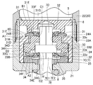
- FIG. 1 is a longitudinal sectional view of the valve 1 in the closed state according to the present embodiment.
- the valve 1 is a diaphragm valve, and is used in a gas line (for example, the most upstream side of the gas line) configured by a plurality of fluid control devices of the fluid control device 55 (FIG. 5). It is a valve.
- the valve 1 includes a body 2, a diaphragm 3, and an actuator 4. In the following description, the valve 1 will be described with the actuator 4 on the upper side and the body 2 on the lower side.
- the body 2 has a cylindrical valve chamber 2a, and an inflow path 2b and an outflow path 2c communicating with the valve chamber 2a.
- An annular seat 2 ⁇ / b> D protruding toward the stem 7 of the actuator 4 is provided at a periphery (an opening of the inflow passage 2 b) of a portion where the inflow passage 2 b of the body 2 communicates with the valve chamber 2 a.
- the sheet 2D is made of a resin material or the like.
- the body 2 is provided so as to extend upward, has a cylindrical shape, and has a cylindrical portion 2E in which a female screw portion is formed on an inner peripheral portion.
- the diaphragm 3 is composed of a plurality of diaphragms, and is disposed in the valve chamber 2a.
- the outer peripheral edge of the diaphragm 3 is narrowed by an annular holding adapter 9 described later, and is held against the body 2.
- the diaphragm 3, which is a valve body, has a substantially spherical shell shape, and an upwardly convex substantially circular arc shape is in a natural state.
- the diaphragm 3 comes into contact with the seat 2D, and the inflow path 2b and the outflow path 2c are shut off.
- the valve 1 is in the open state, the diaphragm 3 is separated from the seat 2D, and the inflow path 2b and the outflow path 2c communicate.
- the actuator 4 includes a casing 20, a piezoelectric element 5, a disk 6, a stem 7, a coil spring 8, a holding adapter 9, a diaphragm holding 10, and a displacement amplifying mechanism 30.
- the casing 20 includes a bonnet 21, an intermediate casing 22, a cap 23, a first support ring 24, and a second support ring 25, and has a substantially closed cylindrical shape as a whole.
- the bonnet 21 has a substantially cylindrical shape, and has a base 21A, an upper cylindrical portion 21B, and a lower cylindrical portion 21C.
- the base 21A has a disk shape having a through hole 21d.
- the upper cylindrical portion 21B has a cylindrical shape and protrudes upward from the outer peripheral edge of the base 21A.
- a male screw portion is formed on the outer periphery of the upper end of the upper cylindrical portion 21B.
- the lower cylindrical portion 21C has a cylindrical shape and protrudes downward from a position between the through hole 21d of the base 21A and the outer peripheral edge.
- a male screw portion is formed on the outer periphery of the lower cylindrical portion 21C.
- the male screw portion of the lower cylindrical portion 21 ⁇ / b> C of the bonnet 21 is screwed to the female screw portion of the cylindrical portion 2 ⁇ / b> E of the body 2 to be fixed to the body 2.
- the intermediate casing 22 has a substantially cylindrical shape having a through hole 22a.
- a female screw portion is formed on the inner periphery of the lower end of the intermediate casing 22, and a male screw portion is formed on the outer periphery of the upper end.
- the female screw part at the lower end of the intermediate casing 22 is screwed into the male screw part of the upper cylindrical part 21 ⁇ / b> B of the bonnet 21, so that the intermediate casing 22 is fixed to the bonnet 21.
- the cap 23 has a closed cylindrical shape.
- a female screw portion is formed on the inner periphery of the lower end of the cap 23.
- the cap 23 is fixed to the intermediate casing 22 by screwing a female thread at the lower end of the cap 23 to a male thread at the upper end of the intermediate casing 22.
- the cap 23 is provided with a plate 23A and a lock nut 23B.
- the first support ring 24 has a substantially cylindrical shape and is disposed on the base 21A of the bonnet 21. At the upper end of the first support ring 24, an annular convex portion 24A protruding inward is provided.
- the outer diameter of the first support ring 24 is configured to be slightly smaller than the inner diameter of the upper cylindrical portion 21B of the bonnet 21.
- the second support ring 25 has a substantially disk shape having a through hole 25a, and is disposed on the base 21A of the bonnet 21.
- a recess 25c is formed at the center of the upper surface 25B of the second support ring 25.
- the second support ring 25 is provided inside the first support ring 24, and the outer diameter of the second support ring 25 is configured to be slightly smaller than the inner diameter of the first support ring 24.
- the piezoelectric element 5 is arranged on a disk 6 described later, and is provided in the intermediate casing 22.
- a pair of lead terminals 5a and 5b are connected to the piezoelectric element 5, and the lead terminals 5a and 5b extend outside through the cap 23 and the plate 23A.
- the piezoelectric element 5 is deformed by the inverse piezoelectric effect.
- the upper end of the piezoelectric element 5 is restricted from being deformed upward by the plate 23A and the lock nut 23B.
- the deformation of the piezoelectric element 5 is transmitted to the lower side, and the disk 6 is displaced.
- the tightening amount of the lock nut 23B the displacement amount of the disk 6 due to the deformation of the piezoelectric element 5 is adjusted.
- the disk 6 is located below the piezoelectric element 5 and is provided so as to be vertically movable within the upper cylindrical portion 21B of the bonnet 21.
- a protruding portion 6A protruding downward is provided.
- a concave portion 6b that is recessed upward is formed.
- an annular protruding portion 6C protruding downward is provided.
- the lower surface 6D of the projection 6C has a planar shape.
- the stem 7 is located below the disk 6 and is provided movably in the vertical direction.
- the stem 7 has an upper stem 7A and a lower stem 7B.
- the upper stem 7A has a disk portion 7C, an upper extension portion 7D, and a lower extension portion 7E.
- the disk portion 7C has a disk shape and is located in the upper cylindrical portion 21B of the bonnet 21.
- the outer diameter of the disk portion 7C is configured to be larger than the outer diameters of the upper extension portion 7D and the lower extension portion 7E.
- the upper extension 7D has a regular hexagonal column shape and extends upward from the center of the disk 7C.
- the upper end of the upper extension 7D is located in the recess 6b of the disk 6, but is configured so as not to contact the disk 6 even if the stem 7 moves up and down.
- the lower extension 7E extends downward from the center of the disk 7C.
- the lower extension 7E has a regular hexagonal column 7E1 and a column 7E2.
- the regular hexagonal column 7E1 is located below the disk 7C, and the column 7E2 is located below the regular hexagonal column 7E1.
- the cylindrical portion 7E2 penetrates the through hole 25a of the second support ring 25 and the through hole 21d of the base 21A, and the lower end of the cylindrical portion 7E2 is located in the lower cylindrical portion 21C. Is formed.
- the lower stem 7B has a substantially cylindrical shape and is located in the lower cylindrical portion 21C.
- a female screw portion is formed on the inner periphery of the upper end of the lower stem 7B.
- the lower stem 7B is fixed to the upper stem 7A by screwing the female screw at the upper end of the lower stem 7B to the male screw at the lower end of the upper stem 7A.
- the coil spring 8 is provided in the lower cylindrical portion 21C, interposed between the base 21A and the lower stem 7B, and constantly biases the stem 7 downward.
- the holding adapter 9 is formed in an annular shape, narrows the outer peripheral edge of the diaphragm 3, and holds the diaphragm 3 on the body 2.
- the diaphragm holder 10 is provided below the stem 7 and can press the center of the diaphragm 3.
- FIG. 2A is a perspective view showing a state where the first lever 31 (second lever 34) and the first retainer 32 (second retainer 35) are combined
- FIG. 2B is a diagram showing the first retainer 32
- FIG. 2C is a perspective view of the (second retainer 35)
- FIG. 2C is a side view of the first lever 31 (second lever 34).
- the first lever 31 and the first retainer 32 in FIG. 2 show a state where the first lever 31 and the first retainer 32 shown in FIGS. Therefore, FIG. 2 illustrates the first lever 31 and the first retainer 32 that are turned upside down.
- the displacement amplification mechanism 30 includes six first levers 31, a first retainer 32, an intermediate member 33, six second levers 34, and a second retainer 35.
- the six first levers 31 correspond to a first lever portion
- the six second retainers 35 correspond to a second lever portion.
- the six first levers 31 each independently have the same shape, and are arranged at equal intervals along the circumferential direction of the casing 20 around the upper extension 7D.
- Each first lever 31 is made of metal (for example, stainless steel), resin, ceramics, or the like, and has a hardness that does not deform (do not distort) when the valve 1 described below opens and closes. That is, each first lever 31 functions as a rigid body with respect to the opening and closing operation of the valve 1.
- Each first lever 31 has an inner portion 31A and an outer portion 31B, and has a shape that tapers from the outer portion 31B toward the inner portion 31A.
- the outer portion 31B is connected to the inner portion 31A so as to bend upward.
- each first lever 31 has the bent portion 31H.
- An insertion hole 31c is formed in the inner part 31A.
- the first lever 31 has a first main surface 31D and a second main surface 31E. Portions constituting the inner portion 31A and the outer portion 31B of the first main surface 31D and the second main surface 31E are each planar.
- each first lever 31 extends so as to be parallel to the tangential direction of a circle centered on the axis of the stem 7. Then, as shown in FIG. 3, each first lever 31 is arranged such that the first main surface 31D faces downward and the second main surface 31E faces upward, and the outer end of each first lever 31. 31F is in line contact with the upper surface 24B of the convex portion 24A of the first support ring 24, and the inner end portion 31G is opposed to each surface of the regular hexagonal prism of the upper extension 7D of the stem 7, and the upper surface 33F of the intermediate member 33 is formed. Is in line contact with The lower surface 6D of the disk 6 is in line contact with the bent portion 31H of the first lever 31 on the second main surface 31E.
- the first retainer 32 is made of a flexible material such as rubber, has a substantially hexagonal shape in plan view, and has a regular hexagonal insertion hole 32a.
- the first retainer 32 has an annular portion 32B, six first projections 32C, and six second projections 32D.
- the six first protrusions 32C each have a substantially cylindrical shape, and are arranged at regular intervals in the circumferential direction of the actuator 4 with respect to the annular portion 32B.
- the six second protrusions 32D are provided between the adjacent first protrusions 32C, and have a shape that tapers toward the center of the annular portion 32B in plan view.
- Each first lever 31 is held by the first retainer 32 by inserting the first protrusion 32C of the first retainer 32 into the insertion hole 31c of the inner portion 31A.
- Each of the first levers 31 is arranged between the adjacent second protrusions 32D, so that the rotation of each of the first levers 31 is suppressed.
- the intermediate member 33 has a substantially annular shape and is located below the first lever 31 and the first retainer 32 as shown in FIG.
- the intermediate member 33 has an upper transmission section 33A and a lower transmission section 33B.
- the upper transmitting portion 33A is located inside the convex portion 24A of the first support ring 24.
- a regular hexagonal upper through-hole 33c is formed at the center of the upper transmission portion 33A.
- the size of the upper through hole 33c is configured to be slightly larger than the size of the upper extension 7D.
- the upper extension 7D passes through the upper through hole 33c.
- a cylindrical intermediate through-hole 33e is formed on the upper transmitting part 33A side of the lower transmitting part 33B, and a lower through-hole 33d is formed below it.
- the inner diameter of the intermediate through hole 33e is configured to be slightly larger than the outer diameter of the disk portion 7C of the stem 7.
- the disk portion 7C can move up and down along the inner periphery of the intermediate through hole 33e.
- the inner diameter of the lower through hole 33d is configured to be larger than the inner diameter of the intermediate through hole 33e.
- the six second levers 34 and the second retainers 35 are located below the intermediate member 33, and have the same configuration and shape as the six first levers 31 and the first retainers 32, respectively, as shown in FIG. .
- each of the second levers 34 is made of metal (for example, stainless steel), resin, ceramics, or the like, has a hardness that does not deform (is not distorted) when opening and closing the valve 1 described below, and has an insertion hole 34c. And an outer portion 34B.
- the outer end 34F and the inner end 34G of each second lever 34 extend so as to be parallel to the tangential direction of a circle centered on the axis of the stem 7.
- the second lever 34 has a third main surface 34D and a fourth main surface 34E, and the inner portion 34A and the outer portion of the third main surface 34D and the fourth main surface 34E.
- the portions constituting the portion 34B are each in the form of a plane.
- the six second levers 34 are arranged at regular intervals along the circumferential direction of the casing 20 around the regular hexagonal column 7E1.
- Each of the second levers 34 is arranged such that the third main surface 34D faces upward and the fourth main surface 34E faces downward.
- the outer end 34F of each first lever 34 is connected to the lower surface 33G of the intermediate member 33.
- the inner end 34G is in line contact with the lower surface 7F of the disc portion 7C of the stem 7 in opposition to each surface of the regular hexagonal column portion 7E1.
- the upper surface 25B of the second support ring 25 is in line contact with the bent portion 34H of the second lever 34 on the second main surface 34E.
- the second retainer 35 is made of a flexible elastic material such as rubber, has a substantially hexagonal annular shape in plan view, and has a regular hexagonal insertion hole 35a.
- the second retainer 35 has an annular portion 35B, six third protrusions 35C, and six fourth protrusions 35D.
- Each second lever 34 is held by the second retainer 35 by inserting the third protrusion 35C of the second retainer 35 into the insertion hole 34c of the inner portion 34A.
- Each of the second levers 34 is disposed between the adjacent fourth protrusions 35D, so that the rotation of each of the second levers 34 is suppressed.
- FIG. 3 is a sectional view of the displacement amplification mechanism 30 when the valve 1 is in the closed state.
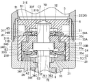
- FIG. 4 is a sectional view of the displacement amplification mechanism 30 when the valve 1 is in the open state.
- each second lever 34 As the intermediate member 33 moves downward, the outer end 34F of each second lever 34 is pushed from the lower surface 33G of the intermediate member 33, and each second lever 34 is bent by the bent portion 34H of each second lever 34. Around the center. As a result, the inner end 34G of each second lever 34 moves upward, the lower surface 7F of the disc portion 7C of the stem 7 is pushed, and the stem 7 moves upward against the urging force of the coil spring 8. Move to.
- the displacement of the disk 6 due to the deformation of the piezoelectric element 5 is amplified by the displacement amplification mechanism 30 and transmitted to the stem 7. That is, the contact portion A1 of the outer end portion 31F of the first lever 31 with respect to the upper surface 24B of the first support ring 24 is the fulcrum, the contact portion B1 of the bent portion 31H of the first lever 31 with the lower surface 6D of the disk 6 is the point of focus,
- the contact portion C1 of the inner end portion 31G of the first lever 31 with respect to the upper surface 33F of the intermediate member 33 is set as the point of action, the distance between the contact portion A1 and the contact portion C1 in the direction orthogonal to the axis of the stem 7 Is several times (in this embodiment, about 3.5 times) the distance between the contact portion A1 and the contact portion B1.
- the displacement of the inner end portion 31G of the first lever 31 is about 3.5 times the displacement of the bent portion 31H of the first lever 31, that is, the displacement of the disk 6 due to the deformation of the piezoelectric element 5, due to the leverage principle.
- the contact portion A2 of the bent portion 34H of the second lever 34 with the upper surface 25B of the second support ring 25 is the fulcrum
- the contact portion B2 of the outer end portion 34F of the second lever 34 with the lower surface 33G of the intermediate member 33 is the power point.
- the contact portion C2 of the inner end portion 34G of the second lever 34 with the lower surface 7F of the disc portion 7C of the stem 7 is set as the point of action
- the contact portion A2 contacts the contact portion A2 in a direction perpendicular to the axis of the stem 7.
- the distance between the contact portion A2 and the contact portion C2 is several times (about 3.5 times in this embodiment) the distance between the contact portion A2 and the contact portion C2.
- the displacement of the inner end 34G of the second lever 34 is about 3.5 times the displacement of the outer end 34 of the second lever 31 due to the principle of leverage. Therefore, the displacement of the inner end 34G of the second lever 34 is about 12 times the displacement of the disk 6 due to the deformation of the piezoelectric element 5.
- the displacement of the disk 6 due to the deformation of the piezoelectric element 5 is amplified by the displacement amplifying mechanism 30 to move the stem 7 upward.
- the displacement amount for example, 20 ⁇ m
- the displacement amount of the stem 7 can be increased.
- the inner end 34 ⁇ / b> G of each second lever 34 is displaced toward the piezoelectric element 5 by the displacement of the piezoelectric element 5 due to voltage application, and moves the stem 7 toward the piezoelectric element 5.
- the normally closed valve 1 can be opened.
- the outer end portion 31F corresponds to a first fulcrum portion
- the bent portion 31H corresponds to a first force point portion
- the inner end portion 31G corresponds to a first action point portion.
- the outer end 34F corresponds to a second point of force
- the bent portion 34H corresponds to a second fulcrum
- the inner end 34G corresponds to a second point of action.
- the bending portion 31H that is the first force point portion is connected to the first fulcrum.
- the bent portion 34H which is a second fulcrum portion, is located between the outer end portion 31F, which is the first portion, and the inner end portion 31G, which is the first point of action, and the outer end portion 34F, which is the second point of force, and the second It is located between the inner end 34G, which is the point of action, and the distance between the bent portion 34H and the inner end 34G is longer than the distance between the bent portion 34H and the outer end 34F.
- each second lever 34 due to the displacement of the intermediate member 33 toward each second lever 34, the inner end 34 ⁇ / b> G of each second lever 34 is displaced toward the piezoelectric element 5 and moves the stem 7 toward the piezoelectric element 5. Therefore, the displacement of the piezoelectric element 5 can be amplified, and the stem 7 can be displaced toward the piezoelectric element 5 by the displacement of the piezoelectric element 5. Therefore, the normally closed valve 1 can be provided.
- the displacement amplifying mechanism 30 has a plurality of first levers 31 and a plurality of second levers 34, by disposing the plurality of levers at equal intervals along the circumferential direction of the stem 7, The force can be evenly transmitted from the element 5 to the stem 7 via the intermediate member 33, and the displacement of the piezoelectric element 5 can be smoothly transmitted to the stem 7.
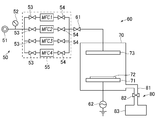
- FIG. 6 is a schematic view of the semiconductor manufacturing apparatus 60.
- the semiconductor manufacturing apparatus 60 is, for example, a CVD apparatus, has a gas supply unit 50 having a fluid control unit 55, a vacuum chamber 70, and an exhaust unit 80, and forms a passivation film (oxide film) on a wafer. It is a device to do.
- the gas supply means 50 includes a gas supply source 51, a pressure gauge 52, and a fluid control device 55.
- the fluid control device 55 has a plurality of gas lines constituted by a plurality of fluid control devices, and includes on-off valves 53 and 54 and MFCs 1 to 4 (mass flow controllers) as the fluid control devices.
- An on-off valve 61 is provided between the gas supply means 50 and the vacuum chamber 70.
- the vacuum chamber 70 includes a mounting table 71 on which a wafer 72 is mounted and an electrode 73 for forming a thin film on the wafer 72.
- the commercial power supply 62 is connected to the vacuum chamber 70.
- the exhaust unit 80 includes an exhaust pipe 81, an on-off valve 82, and a dust collector 83.
- the supply of gas to the vacuum chamber 70 is controlled by opening and closing the on-off valves 53 and 54, and opening and closing the MFCs 1 to 4 and the on-off valve 61. Further, when removing the particulates as by-products generated when a thin film is formed on the wafer 72, the on-off valve 82 is opened, and the particulates are removed by the dust collector 83 through the exhaust pipe 81. You.
- valve 1 in the present embodiment can be applied to the on-off valves 53, 54, 61, 82. As described above, since the valve 1 has excellent durability, it is possible to provide the fluid control device 55 having excellent durability.
- the etching device (dry etching device) is a device that includes a processing chamber, gas supply means (fluid control device), and exhaust means, and processes a material surface or the like by a corrosive action of a reactive gas.
- the sputtering apparatus includes a target, a vacuum chamber, a gas supply unit (fluid control unit), and an exhaust unit, and is a device that forms a film on a material surface.
- the displacement amplifying mechanism 30 in the above-described embodiment includes the six first levers 31, the first retainer 32, the intermediate member 33, the six second levers 34, and the second retainer 35.
- the first retainer 32 and the second retainer 35 may not be provided.
- the first lever portion and the second lever portion are each constituted by six independent members, but the six first levers 31 or the six second levers 34 are connected at their inner peripheral edge or outer peripheral edge. It may be an integrated structure.
- the first lever 31 or the second lever 34 may be made of a material such as a metal or a resin that is deformed according to the displacement of the disk 6 and the intermediate member 33.
- the displacement amplification mechanism 30 has the six first levers 31 and the six second levers 34, it is sufficient that each of the two mechanisms is two or more.
- the coil spring 8 may be constituted by a disc spring.
- the valve seat is configured by embedding an annular sheet 2D made of resin, an annular convex portion may be formed by the same metal material as the body 2 to configure the valve seat.
- valve 1: valve, 2: body, 2b: inflow path, 2c: outflow path, 3: diaphragm, 4: actuator, 5: piezoelectric element, 7: stem, 20: casing, 30: displacement amplification mechanism, 31: first lever portion, 31F: outer end portion, 31G: inner end portion, 31H: bent portion, 33: intermediate member, 34: second lever portion, 34F: outer end portion, 34G: Inner end, 34H: bent portion, 55: fluid control device
Landscapes
- Engineering & Computer Science (AREA)
- General Engineering & Computer Science (AREA)
- Mechanical Engineering (AREA)
- Electrically Driven Valve-Operating Means (AREA)
Abstract
Description
30:変位増幅機構、 31:第1レバー部、 31F:外端部、 31G:内端部、 31H:屈曲部、 33:中間部材、 34:第2レバー部、 34F:外端部、 34G:内端部、 34H:屈曲部、 55:流体制御装置
Claims (5)
- ケーシングと、
前記ケーシング内に設けられたステムと、
前記ステムへ向かって変位するように前記ケーシングに支持された圧電素子と、
前記圧電素子の変位を増幅させる変位増幅機構と、を備え、
前記変位増幅機構は、第1レバー部と、中間部材と、第2レバー部とを有し、
前記第1レバー部は、前記圧電素子と前記中間部材との間に位置し、前記圧電素子からの変位を受ける第1力点部と、前記ケーシングに当接して前記第1レバー部の回動の中心となる第1支点部と、前記中間部材へ変位を伝える第1作用点部と、を有し、
前記中間部材は、前記第1レバー部と前記第2レバー部との間に位置し、前記第1レバー部からの変位を受けて、前記第2レバー部に向かって変位するように構成され、
前記第2レバー部は、前記中間部材からの変位を受ける第2力点部と、前記ケーシングに当接して前記第2レバー部の回動の中心となる第2支点部と、前記ステムへ変位を伝える第2作用点部と、を有し、
前記ステムの軸に対し直交する方向において、前記第1力点部は、前記第1支点部と前記第1作用点部との間に位置し、
前記ステムの軸に対し直交する方向において、前記第2支点部は、前記第2力点部と前記第2作用点部との間に位置し、
前記第2支点部と前記第2作用点部との距離は、前記第2支点部と前記第2力点部との距離よりも長く構成され、
前記中間部材の前記第2レバー部側への変位により、前記第2レバー部の前記第2作用点部は、前記ステムに向かって変位し、前記ステムを前記圧電素子に向かって移動させる、アクチュエータ。 - 前記第1レバー部は、前記ステムの周方向に沿って配置された複数の第1レバーを有し、
前記第2レバー部は、前記ステムの周方向に沿って配置された複数の第2レバーを有する、請求項1に記載のアクチュエータ。 - 前記変位増幅機構は、前記複数の第1レバーを保持する第1リテーナと、前記複数の第1レバーを保持する第1リテーナとを備える、請求項2に記載のアクチュエータ。
- 流体通路が形成されたボディと、
前記流体通路を開閉する弁体と、
請求項1から請求項3のいずれか一項に記載のアクチュエータと、を備えるバルブ。 - 複数の流体制御機器により構成される流体制御装置であって、
前記複数の流体制御機器の少なくとも一つは、請求項4に記載のバルブである流体制御装置。
Priority Applications (6)
| Application Number | Priority Date | Filing Date | Title |
|---|---|---|---|
| KR1020217003193A KR20210025647A (ko) | 2018-07-31 | 2019-06-03 | 액추에이터, 밸브, 및 유체 제어 장치 |
| JP2020534078A JP7279954B2 (ja) | 2018-07-31 | 2019-06-03 | アクチュエータ、バルブ、および流体制御装置 |
| SG11202100877QA SG11202100877QA (en) | 2018-07-31 | 2019-06-03 | Actuator, valve device, and fluid control apparatus |
| EP19843492.0A EP3832182B1 (en) | 2018-07-31 | 2019-06-03 | Actuator, valve, and fluid control device |
| CN201980040514.0A CN112334695A (zh) | 2018-07-31 | 2019-06-03 | 致动器、阀、及流体控制装置 |
| US17/162,489 US11231121B2 (en) | 2018-07-31 | 2021-01-29 | Actuator, valve device, and fluid control apparatus |
Applications Claiming Priority (2)
| Application Number | Priority Date | Filing Date | Title |
|---|---|---|---|
| JP2018-143972 | 2018-07-31 | ||
| JP2018143972 | 2018-07-31 |
Related Child Applications (1)
| Application Number | Title | Priority Date | Filing Date |
|---|---|---|---|
| US17/162,489 Continuation US11231121B2 (en) | 2018-07-31 | 2021-01-29 | Actuator, valve device, and fluid control apparatus |
Publications (1)
| Publication Number | Publication Date |
|---|---|
| WO2020026580A1 true WO2020026580A1 (ja) | 2020-02-06 |
Family
ID=69231680
Family Applications (1)
| Application Number | Title | Priority Date | Filing Date |
|---|---|---|---|
| PCT/JP2019/021983 Ceased WO2020026580A1 (ja) | 2018-07-31 | 2019-06-03 | アクチュエータ、バルブ、および流体制御装置 |
Country Status (8)
| Country | Link |
|---|---|
| US (1) | US11231121B2 (ja) |
| EP (1) | EP3832182B1 (ja) |
| JP (1) | JP7279954B2 (ja) |
| KR (1) | KR20210025647A (ja) |
| CN (1) | CN112334695A (ja) |
| SG (1) | SG11202100877QA (ja) |
| TW (1) | TWI709705B (ja) |
| WO (1) | WO2020026580A1 (ja) |
Families Citing this family (3)
| Publication number | Priority date | Publication date | Assignee | Title |
|---|---|---|---|---|
| CN112196757A (zh) * | 2020-10-04 | 2021-01-08 | 长春工业大学 | 一种双杠杆放大的压电叠堆柱塞泵 |
| CN116085515B (zh) * | 2023-01-06 | 2026-02-17 | 北京天玛智控科技股份有限公司 | 多路换向阀控制系统 |
| JP2024158472A (ja) * | 2023-04-27 | 2024-11-08 | 株式会社堀場エステック | 流体制御弁及び流体制御装置 |
Citations (3)
| Publication number | Priority date | Publication date | Assignee | Title |
|---|---|---|---|---|
| JPS63262065A (ja) * | 1987-04-16 | 1988-10-28 | Nippon Denso Co Ltd | 圧電アクチユエ−タの変位拡大装置 |
| JPH01210673A (ja) * | 1988-02-17 | 1989-08-24 | Nec Corp | 推進剤供給用高速開閉バルブ |
| JP2003199366A (ja) | 2001-12-26 | 2003-07-11 | Stec Inc | ピエゾアクチュエータ |
Family Cites Families (46)
| Publication number | Priority date | Publication date | Assignee | Title |
|---|---|---|---|---|
| US1967418A (en) * | 1931-08-17 | 1934-07-24 | Copeland Refrigeration Corp | Valve structure |
| US2310570A (en) * | 1937-10-30 | 1943-02-09 | I A Simon | Stabilizer |
| US2634123A (en) * | 1949-11-15 | 1953-04-07 | Ralston Eldon Kipp | Movement multiplier for disk springs |
| US2777461A (en) * | 1951-05-08 | 1957-01-15 | Wildhaber Ernest | Fuel tank filling apparatus with automatic shut-off |
| US2989982A (en) * | 1958-07-15 | 1961-06-27 | Leslie Co | Pressure reducing valve |
| US3302662A (en) * | 1964-05-21 | 1967-02-07 | James E Webb | Antiflutter ball check valve |
| US3690460A (en) * | 1971-03-11 | 1972-09-12 | Ross W Lyon | Relief valve for oil filters or the like |
| US3812766A (en) * | 1972-04-28 | 1974-05-28 | D Weiss | Work locating apparatus |
| US3757910A (en) * | 1971-07-29 | 1973-09-11 | Monroe Auto Equipment Co | Shock absorber and compression valve assembly |
| CH576604A5 (ja) * | 1974-03-29 | 1976-06-15 | Balzers Patent Beteilig Ag | |
| DE2743829C2 (de) * | 1977-09-29 | 1984-03-29 | Festo-Maschinenfabrik Gottlieb Stoll, 7300 Esslingen | Mehrwegeventil |
| US4381796A (en) * | 1980-04-29 | 1983-05-03 | Andre Stockli | Automatic pressure valve |
| US4500270A (en) * | 1982-07-29 | 1985-02-19 | Walbro Corporation | Gear rotor fuel pump |
| US4569504A (en) * | 1983-05-20 | 1986-02-11 | Doyle Michael J | Solenoid |
| US4609178A (en) * | 1984-02-02 | 1986-09-02 | Baumann Hans D | Diaphragm type control valve |
| US4549719A (en) * | 1984-02-02 | 1985-10-29 | Baumann Hans D | Mechanical amplifying means for valves and other devices |
| US4593658A (en) * | 1984-05-01 | 1986-06-10 | Moloney Paul J | Valve operating mechanism for internal combustion and like-valved engines |
| US4729544A (en) * | 1987-05-07 | 1988-03-08 | Baumann Hans D | Electric-powered, lever-amplified actuating means for valves and other devices |
| US4955582A (en) * | 1989-08-14 | 1990-09-11 | Baumann Hans D | Weirless diaphragm valve |
| US5211341A (en) * | 1991-04-12 | 1993-05-18 | Siemens Automotive L.P. | Fuel injector valve having a collared sphere valve element |
| US5211372A (en) * | 1991-07-11 | 1993-05-18 | Massachusetts Institute Of Technology | Exhaust valve for a gas expansion system |
| US5314164A (en) * | 1992-07-17 | 1994-05-24 | Mks Instruments, Inc. | Pivotal diaphragm, flow control valve |
| JP3616855B2 (ja) * | 1995-03-13 | 2005-02-02 | 株式会社フジキン | 制御器 |
| US6059259A (en) * | 1997-12-31 | 2000-05-09 | Advanced Pressure Technology | Pneumatic valve actuator utilizing force multiplication |
| JP2000193007A (ja) * | 1998-12-22 | 2000-07-14 | Fukoku Co Ltd | 板バネ一体型コアおよびその製造方法 |
| DE10044389A1 (de) * | 2000-09-08 | 2002-04-04 | Bosch Gmbh Robert | Ventil zum Steuern von Flüssigkeiten |
| US6547214B2 (en) * | 2001-05-08 | 2003-04-15 | Roger J. Gregoire | Serpentine actuator disk |
| US6764286B2 (en) * | 2001-10-29 | 2004-07-20 | Kelsey-Hayes Company | Piston pump with pump inlet check valve |
| DE50202482D1 (de) * | 2002-06-11 | 2005-04-21 | Festo Ag & Co | Magnetventil |
| JP4300345B2 (ja) * | 2002-09-02 | 2009-07-22 | 株式会社フジキン | 制御器 |
| US6776388B2 (en) * | 2002-09-30 | 2004-08-17 | Hans D. Baumann | Valve actuator with internal amplifying means |
| US7694855B2 (en) * | 2004-04-23 | 2010-04-13 | Nordson Corporation | Dispenser having a pivoting actuator assembly |
| US7712723B2 (en) * | 2006-08-30 | 2010-05-11 | Fisher Controls International Llc | Lever positioning device for valve actuator |
| JP5129609B2 (ja) * | 2008-02-27 | 2013-01-30 | 株式会社フジキン | 圧電素子駆動式ダイヤフラム型制御弁 |
| EP2384406A1 (en) * | 2009-03-16 | 2011-11-09 | Artemis Intelligent Power Limited | Electronically controlled valves |
| DE202010010279U1 (de) * | 2010-07-15 | 2010-11-18 | Bürkert Werke GmbH | Magnetventil |
| GB201018553D0 (en) * | 2010-11-03 | 2010-12-15 | Aker Solutions Singapore Pte Ltd | Valve actuator |
| JP5978035B2 (ja) * | 2012-07-13 | 2016-08-24 | 株式会社フジキン | 流体制御器用アクチュエータ |
| JP5775110B2 (ja) * | 2013-03-26 | 2015-09-09 | 株式会社フジキン | 流量制御装置用の流量制御弁 |
| CN103170966B (zh) * | 2013-04-02 | 2016-04-20 | 西安电子科技大学 | 一种全柔顺微位移放大机构 |
| JP6606079B2 (ja) * | 2013-09-04 | 2019-11-13 | 株式会社堀場エステック | インターレース昇降機構 |
| CN203500336U (zh) * | 2013-09-29 | 2014-03-26 | 江苏理工学院 | 车辆电子机械制动系统压电式制动执行机构 |
| KR101588771B1 (ko) * | 2014-05-12 | 2016-01-26 | 현대자동차 주식회사 | 압전 액츄에이터를 이용한 밸브 구동장치 |
| JP6475441B2 (ja) * | 2014-09-01 | 2019-02-27 | 株式会社フジキン | 圧電素子駆動式バルブ及び圧電素子駆動式バルブを備えた流量制御装置 |
| CN104440817B (zh) * | 2014-12-04 | 2017-04-12 | 山东大学 | 一种空间三维微位移精密定位装置 |
| KR102345939B1 (ko) * | 2017-09-28 | 2021-12-30 | 가부시키가이샤 후지킨 | 액추에이터, 밸브, 및 유체 제어 장치 |
-
2019
- 2019-06-03 KR KR1020217003193A patent/KR20210025647A/ko not_active Ceased
- 2019-06-03 WO PCT/JP2019/021983 patent/WO2020026580A1/ja not_active Ceased
- 2019-06-03 EP EP19843492.0A patent/EP3832182B1/en active Active
- 2019-06-03 CN CN201980040514.0A patent/CN112334695A/zh active Pending
- 2019-06-03 SG SG11202100877QA patent/SG11202100877QA/en unknown
- 2019-06-03 JP JP2020534078A patent/JP7279954B2/ja active Active
- 2019-06-06 TW TW108119678A patent/TWI709705B/zh not_active IP Right Cessation
-
2021
- 2021-01-29 US US17/162,489 patent/US11231121B2/en not_active Expired - Fee Related
Patent Citations (3)
| Publication number | Priority date | Publication date | Assignee | Title |
|---|---|---|---|---|
| JPS63262065A (ja) * | 1987-04-16 | 1988-10-28 | Nippon Denso Co Ltd | 圧電アクチユエ−タの変位拡大装置 |
| JPH01210673A (ja) * | 1988-02-17 | 1989-08-24 | Nec Corp | 推進剤供給用高速開閉バルブ |
| JP2003199366A (ja) | 2001-12-26 | 2003-07-11 | Stec Inc | ピエゾアクチュエータ |
Non-Patent Citations (1)
| Title |
|---|
| See also references of EP3832182A4 |
Also Published As
| Publication number | Publication date |
|---|---|
| EP3832182A4 (en) | 2022-05-04 |
| CN112334695A (zh) | 2021-02-05 |
| EP3832182A1 (en) | 2021-06-09 |
| TWI709705B (zh) | 2020-11-11 |
| SG11202100877QA (en) | 2021-03-30 |
| JP7279954B2 (ja) | 2023-05-23 |
| KR20210025647A (ko) | 2021-03-09 |
| TW202007890A (zh) | 2020-02-16 |
| US11231121B2 (en) | 2022-01-25 |
| JPWO2020026580A1 (ja) | 2021-08-02 |
| US20210199210A1 (en) | 2021-07-01 |
| EP3832182B1 (en) | 2023-03-29 |
Similar Documents
| Publication | Publication Date | Title |
|---|---|---|
| WO2020026580A1 (ja) | アクチュエータ、バルブ、および流体制御装置 | |
| JP7257056B2 (ja) | バルブ装置および流体制御装置、流体制御方法、半導体製造装置及び半導体製造方法 | |
| TWI698729B (zh) | 閥裝置、流體控制裝置、流體控制方法、半導體製造裝置及半導體製造方法 | |
| TWI701403B (zh) | 閥裝置、使用此閥裝置的流量控制方法及半導體製造方法 | |
| KR102503774B1 (ko) | 밸브 장치 | |
| JP7202597B2 (ja) | アクチュエータおよびこれを用いたバルブ装置 | |
| US11067195B2 (en) | Actuator, valve device, and fluid control apparatus | |
| JP2019065867A (ja) | アクチュエータ、バルブ、および流体制御装置 | |
| JP6933369B2 (ja) | アクチュエータ、バルブ、および流体制御装置 | |
| JP7025915B2 (ja) | ダイヤフラムバルブ | |
| JP2019065866A (ja) | アクチュエータ、バルブ、および流体制御装置 | |
| JP7645536B2 (ja) | バルブ用アクチュエータ及びこれを用いたバルブ | |
| JP7625304B2 (ja) | ダイヤフラムバルブおよび流量制御装置 | |
| JP2021071129A (ja) | シートおよびバルブ | |
| JP7352947B2 (ja) | バルブ装置及び分流システム | |
| JP2023148578A (ja) | ダイヤフラムバルブ | |
| JP2021085483A (ja) | ダイヤフラムバルブおよびダイヤフラム | |
| CN112955685A (zh) | 阀装置和气体供给系统 |
Legal Events
| Date | Code | Title | Description |
|---|---|---|---|
| 121 | Ep: the epo has been informed by wipo that ep was designated in this application |
Ref document number: 19843492 Country of ref document: EP Kind code of ref document: A1 |
|
| ENP | Entry into the national phase |
Ref document number: 2020534078 Country of ref document: JP Kind code of ref document: A |
|
| ENP | Entry into the national phase |
Ref document number: 20217003193 Country of ref document: KR Kind code of ref document: A |
|
| NENP | Non-entry into the national phase |
Ref country code: DE |
|
| ENP | Entry into the national phase |
Ref document number: 2019843492 Country of ref document: EP Effective date: 20210301 |