WO2020026811A1 - 圧力容器及び圧力容器の製造方法 - Google Patents
圧力容器及び圧力容器の製造方法 Download PDFInfo
- Publication number
- WO2020026811A1 WO2020026811A1 PCT/JP2019/028071 JP2019028071W WO2020026811A1 WO 2020026811 A1 WO2020026811 A1 WO 2020026811A1 JP 2019028071 W JP2019028071 W JP 2019028071W WO 2020026811 A1 WO2020026811 A1 WO 2020026811A1
- Authority
- WO
- WIPO (PCT)
- Prior art keywords
- liner
- axial direction
- dome
- yarn
- yarns
- Prior art date
- Legal status (The legal status is an assumption and is not a legal conclusion. Google has not performed a legal analysis and makes no representation as to the accuracy of the status listed.)
- Ceased
Links
Images



Classifications
-
- F—MECHANICAL ENGINEERING; LIGHTING; HEATING; WEAPONS; BLASTING
- F17—STORING OR DISTRIBUTING GASES OR LIQUIDS
- F17C—VESSELS FOR CONTAINING OR STORING COMPRESSED, LIQUEFIED OR SOLIDIFIED GASES; FIXED-CAPACITY GAS-HOLDERS; FILLING VESSELS WITH, OR DISCHARGING FROM VESSELS, COMPRESSED, LIQUEFIED, OR SOLIDIFIED GASES
- F17C1/00—Pressure vessels, e.g. gas cylinder, gas tank, replaceable cartridge
- F17C1/02—Pressure vessels, e.g. gas cylinder, gas tank, replaceable cartridge involving reinforcing arrangements
- F17C1/04—Protecting sheathings
- F17C1/06—Protecting sheathings built-up from wound-on bands or filamentary material, e.g. wires
-
- F—MECHANICAL ENGINEERING; LIGHTING; HEATING; WEAPONS; BLASTING
- F16—ENGINEERING ELEMENTS AND UNITS; GENERAL MEASURES FOR PRODUCING AND MAINTAINING EFFECTIVE FUNCTIONING OF MACHINES OR INSTALLATIONS; THERMAL INSULATION IN GENERAL
- F16J—PISTONS; CYLINDERS; SEALINGS
- F16J12/00—Pressure vessels in general
-
- B—PERFORMING OPERATIONS; TRANSPORTING
- B29—WORKING OF PLASTICS; WORKING OF SUBSTANCES IN A PLASTIC STATE IN GENERAL
- B29C—SHAPING OR JOINING OF PLASTICS; SHAPING OF MATERIAL IN A PLASTIC STATE, NOT OTHERWISE PROVIDED FOR; AFTER-TREATMENT OF THE SHAPED PRODUCTS, e.g. REPAIRING
- B29C63/00—Lining or sheathing, i.e. applying preformed layers or sheathings of plastics; Apparatus therefor
- B29C63/0004—Component parts, details or accessories; Auxiliary operations
-
- B—PERFORMING OPERATIONS; TRANSPORTING
- B29—WORKING OF PLASTICS; WORKING OF SUBSTANCES IN A PLASTIC STATE IN GENERAL
- B29C—SHAPING OR JOINING OF PLASTICS; SHAPING OF MATERIAL IN A PLASTIC STATE, NOT OTHERWISE PROVIDED FOR; AFTER-TREATMENT OF THE SHAPED PRODUCTS, e.g. REPAIRING
- B29C63/00—Lining or sheathing, i.e. applying preformed layers or sheathings of plastics; Apparatus therefor
- B29C63/0017—Lining or sheathing, i.e. applying preformed layers or sheathings of plastics; Apparatus therefor characterised by the choice of the material
- B29C63/0021—Lining or sheathing, i.e. applying preformed layers or sheathings of plastics; Apparatus therefor characterised by the choice of the material with coherent impregnated reinforcing layers
-
- B—PERFORMING OPERATIONS; TRANSPORTING
- B29—WORKING OF PLASTICS; WORKING OF SUBSTANCES IN A PLASTIC STATE IN GENERAL
- B29C—SHAPING OR JOINING OF PLASTICS; SHAPING OF MATERIAL IN A PLASTIC STATE, NOT OTHERWISE PROVIDED FOR; AFTER-TREATMENT OF THE SHAPED PRODUCTS, e.g. REPAIRING
- B29C63/00—Lining or sheathing, i.e. applying preformed layers or sheathings of plastics; Apparatus therefor
- B29C63/02—Lining or sheathing, i.e. applying preformed layers or sheathings of plastics; Apparatus therefor using sheet or web-like material
- B29C63/04—Lining or sheathing, i.e. applying preformed layers or sheathings of plastics; Apparatus therefor using sheet or web-like material by folding, winding, bending or the like
-
- B—PERFORMING OPERATIONS; TRANSPORTING
- B29—WORKING OF PLASTICS; WORKING OF SUBSTANCES IN A PLASTIC STATE IN GENERAL
- B29C—SHAPING OR JOINING OF PLASTICS; SHAPING OF MATERIAL IN A PLASTIC STATE, NOT OTHERWISE PROVIDED FOR; AFTER-TREATMENT OF THE SHAPED PRODUCTS, e.g. REPAIRING
- B29C70/00—Shaping composites, i.e. plastics material comprising reinforcements, fillers or preformed parts, e.g. inserts
- B29C70/04—Shaping composites, i.e. plastics material comprising reinforcements, fillers or preformed parts, e.g. inserts comprising reinforcements only, e.g. self-reinforcing plastics
- B29C70/06—Fibrous reinforcements only
- B29C70/08—Fibrous reinforcements only comprising combinations of different forms of fibrous reinforcements incorporated in matrix material, forming one or more layers, and with or without non-reinforced layers
- B29C70/083—Combinations of continuous fibres or fibrous profiled structures oriented in one direction and reinforcements forming a two dimensional structure, e.g. mats
- B29C70/085—Combinations of continuous fibres or fibrous profiled structures oriented in one direction and reinforcements forming a two dimensional structure, e.g. mats the structure being deformed in a three dimensional configuration
-
- B—PERFORMING OPERATIONS; TRANSPORTING
- B29—WORKING OF PLASTICS; WORKING OF SUBSTANCES IN A PLASTIC STATE IN GENERAL
- B29C—SHAPING OR JOINING OF PLASTICS; SHAPING OF MATERIAL IN A PLASTIC STATE, NOT OTHERWISE PROVIDED FOR; AFTER-TREATMENT OF THE SHAPED PRODUCTS, e.g. REPAIRING
- B29C70/00—Shaping composites, i.e. plastics material comprising reinforcements, fillers or preformed parts, e.g. inserts
- B29C70/04—Shaping composites, i.e. plastics material comprising reinforcements, fillers or preformed parts, e.g. inserts comprising reinforcements only, e.g. self-reinforcing plastics
- B29C70/06—Fibrous reinforcements only
- B29C70/10—Fibrous reinforcements only characterised by the structure of fibrous reinforcements, e.g. hollow fibres
- B29C70/16—Fibrous reinforcements only characterised by the structure of fibrous reinforcements, e.g. hollow fibres using fibres of substantial or continuous length
- B29C70/22—Fibrous reinforcements only characterised by the structure of fibrous reinforcements, e.g. hollow fibres using fibres of substantial or continuous length oriented in at least two directions forming a two-dimensional [2D] structure
- B29C70/222—Fibrous reinforcements only characterised by the structure of fibrous reinforcements, e.g. hollow fibres using fibres of substantial or continuous length oriented in at least two directions forming a two-dimensional [2D] structure the structure being shaped to form a three dimensional configuration
-
- B—PERFORMING OPERATIONS; TRANSPORTING
- B29—WORKING OF PLASTICS; WORKING OF SUBSTANCES IN A PLASTIC STATE IN GENERAL
- B29C—SHAPING OR JOINING OF PLASTICS; SHAPING OF MATERIAL IN A PLASTIC STATE, NOT OTHERWISE PROVIDED FOR; AFTER-TREATMENT OF THE SHAPED PRODUCTS, e.g. REPAIRING
- B29C70/00—Shaping composites, i.e. plastics material comprising reinforcements, fillers or preformed parts, e.g. inserts
- B29C70/04—Shaping composites, i.e. plastics material comprising reinforcements, fillers or preformed parts, e.g. inserts comprising reinforcements only, e.g. self-reinforcing plastics
- B29C70/28—Shaping operations therefor
- B29C70/30—Shaping by lay-up, i.e. applying fibres, tape or broadsheet on a mould, former or core; Shaping by spray-up, i.e. spraying of fibres on a mould, former or core
- B29C70/32—Shaping by lay-up, i.e. applying fibres, tape or broadsheet on a mould, former or core; Shaping by spray-up, i.e. spraying of fibres on a mould, former or core on a rotating mould, former or core
-
- B—PERFORMING OPERATIONS; TRANSPORTING
- B29—WORKING OF PLASTICS; WORKING OF SUBSTANCES IN A PLASTIC STATE IN GENERAL
- B29D—PRODUCING PARTICULAR ARTICLES FROM PLASTICS OR FROM SUBSTANCES IN A PLASTIC STATE
- B29D22/00—Producing hollow articles
- B29D22/003—Containers for packaging, storing or transporting, e.g. bottles, jars, cans, barrels, tanks
-
- B—PERFORMING OPERATIONS; TRANSPORTING
- B29—WORKING OF PLASTICS; WORKING OF SUBSTANCES IN A PLASTIC STATE IN GENERAL
- B29L—INDEXING SCHEME ASSOCIATED WITH SUBCLASS B29C, RELATING TO PARTICULAR ARTICLES
- B29L2031/00—Other particular articles
- B29L2031/712—Containers; Packaging elements or accessories, Packages
- B29L2031/7154—Barrels, drums, tuns, vats
- B29L2031/7156—Pressure vessels
-
- F—MECHANICAL ENGINEERING; LIGHTING; HEATING; WEAPONS; BLASTING
- F17—STORING OR DISTRIBUTING GASES OR LIQUIDS
- F17C—VESSELS FOR CONTAINING OR STORING COMPRESSED, LIQUEFIED OR SOLIDIFIED GASES; FIXED-CAPACITY GAS-HOLDERS; FILLING VESSELS WITH, OR DISCHARGING FROM VESSELS, COMPRESSED, LIQUEFIED, OR SOLIDIFIED GASES
- F17C2201/00—Vessel construction, in particular geometry, arrangement or size
- F17C2201/01—Shape
- F17C2201/0104—Shape cylindrical
- F17C2201/0109—Shape cylindrical with exteriorly curved end-piece
-
- F—MECHANICAL ENGINEERING; LIGHTING; HEATING; WEAPONS; BLASTING
- F17—STORING OR DISTRIBUTING GASES OR LIQUIDS
- F17C—VESSELS FOR CONTAINING OR STORING COMPRESSED, LIQUEFIED OR SOLIDIFIED GASES; FIXED-CAPACITY GAS-HOLDERS; FILLING VESSELS WITH, OR DISCHARGING FROM VESSELS, COMPRESSED, LIQUEFIED, OR SOLIDIFIED GASES
- F17C2201/00—Vessel construction, in particular geometry, arrangement or size
- F17C2201/05—Size
- F17C2201/056—Small (<1 m3)
-
- F—MECHANICAL ENGINEERING; LIGHTING; HEATING; WEAPONS; BLASTING
- F17—STORING OR DISTRIBUTING GASES OR LIQUIDS
- F17C—VESSELS FOR CONTAINING OR STORING COMPRESSED, LIQUEFIED OR SOLIDIFIED GASES; FIXED-CAPACITY GAS-HOLDERS; FILLING VESSELS WITH, OR DISCHARGING FROM VESSELS, COMPRESSED, LIQUEFIED, OR SOLIDIFIED GASES
- F17C2203/00—Vessel construction, in particular walls or details thereof
- F17C2203/06—Materials for walls or layers thereof; Properties or structures of walls or their materials
- F17C2203/0602—Wall structures; Special features thereof
- F17C2203/0604—Liners
-
- F—MECHANICAL ENGINEERING; LIGHTING; HEATING; WEAPONS; BLASTING
- F17—STORING OR DISTRIBUTING GASES OR LIQUIDS
- F17C—VESSELS FOR CONTAINING OR STORING COMPRESSED, LIQUEFIED OR SOLIDIFIED GASES; FIXED-CAPACITY GAS-HOLDERS; FILLING VESSELS WITH, OR DISCHARGING FROM VESSELS, COMPRESSED, LIQUEFIED, OR SOLIDIFIED GASES
- F17C2203/00—Vessel construction, in particular walls or details thereof
- F17C2203/06—Materials for walls or layers thereof; Properties or structures of walls or their materials
- F17C2203/0602—Wall structures; Special features thereof
- F17C2203/0612—Wall structures
- F17C2203/0614—Single wall
- F17C2203/0619—Single wall with two layers
-
- F—MECHANICAL ENGINEERING; LIGHTING; HEATING; WEAPONS; BLASTING
- F17—STORING OR DISTRIBUTING GASES OR LIQUIDS
- F17C—VESSELS FOR CONTAINING OR STORING COMPRESSED, LIQUEFIED OR SOLIDIFIED GASES; FIXED-CAPACITY GAS-HOLDERS; FILLING VESSELS WITH, OR DISCHARGING FROM VESSELS, COMPRESSED, LIQUEFIED, OR SOLIDIFIED GASES
- F17C2203/00—Vessel construction, in particular walls or details thereof
- F17C2203/06—Materials for walls or layers thereof; Properties or structures of walls or their materials
- F17C2203/0634—Materials for walls or layers thereof
- F17C2203/0636—Metals
- F17C2203/0646—Aluminium
-
- F—MECHANICAL ENGINEERING; LIGHTING; HEATING; WEAPONS; BLASTING
- F17—STORING OR DISTRIBUTING GASES OR LIQUIDS
- F17C—VESSELS FOR CONTAINING OR STORING COMPRESSED, LIQUEFIED OR SOLIDIFIED GASES; FIXED-CAPACITY GAS-HOLDERS; FILLING VESSELS WITH, OR DISCHARGING FROM VESSELS, COMPRESSED, LIQUEFIED, OR SOLIDIFIED GASES
- F17C2203/00—Vessel construction, in particular walls or details thereof
- F17C2203/06—Materials for walls or layers thereof; Properties or structures of walls or their materials
- F17C2203/0634—Materials for walls or layers thereof
- F17C2203/0636—Metals
- F17C2203/0648—Alloys or compositions of metals
-
- F—MECHANICAL ENGINEERING; LIGHTING; HEATING; WEAPONS; BLASTING
- F17—STORING OR DISTRIBUTING GASES OR LIQUIDS
- F17C—VESSELS FOR CONTAINING OR STORING COMPRESSED, LIQUEFIED OR SOLIDIFIED GASES; FIXED-CAPACITY GAS-HOLDERS; FILLING VESSELS WITH, OR DISCHARGING FROM VESSELS, COMPRESSED, LIQUEFIED, OR SOLIDIFIED GASES
- F17C2203/00—Vessel construction, in particular walls or details thereof
- F17C2203/06—Materials for walls or layers thereof; Properties or structures of walls or their materials
- F17C2203/0634—Materials for walls or layers thereof
- F17C2203/0658—Synthetics
- F17C2203/066—Plastics
-
- F—MECHANICAL ENGINEERING; LIGHTING; HEATING; WEAPONS; BLASTING
- F17—STORING OR DISTRIBUTING GASES OR LIQUIDS
- F17C—VESSELS FOR CONTAINING OR STORING COMPRESSED, LIQUEFIED OR SOLIDIFIED GASES; FIXED-CAPACITY GAS-HOLDERS; FILLING VESSELS WITH, OR DISCHARGING FROM VESSELS, COMPRESSED, LIQUEFIED, OR SOLIDIFIED GASES
- F17C2203/00—Vessel construction, in particular walls or details thereof
- F17C2203/06—Materials for walls or layers thereof; Properties or structures of walls or their materials
- F17C2203/0634—Materials for walls or layers thereof
- F17C2203/0658—Synthetics
- F17C2203/0663—Synthetics in form of fibers or filaments
- F17C2203/0665—Synthetics in form of fibers or filaments radially wound
-
- F—MECHANICAL ENGINEERING; LIGHTING; HEATING; WEAPONS; BLASTING
- F17—STORING OR DISTRIBUTING GASES OR LIQUIDS
- F17C—VESSELS FOR CONTAINING OR STORING COMPRESSED, LIQUEFIED OR SOLIDIFIED GASES; FIXED-CAPACITY GAS-HOLDERS; FILLING VESSELS WITH, OR DISCHARGING FROM VESSELS, COMPRESSED, LIQUEFIED, OR SOLIDIFIED GASES
- F17C2203/00—Vessel construction, in particular walls or details thereof
- F17C2203/06—Materials for walls or layers thereof; Properties or structures of walls or their materials
- F17C2203/0634—Materials for walls or layers thereof
- F17C2203/0658—Synthetics
- F17C2203/0663—Synthetics in form of fibers or filaments
- F17C2203/0668—Synthetics in form of fibers or filaments axially wound
-
- F—MECHANICAL ENGINEERING; LIGHTING; HEATING; WEAPONS; BLASTING
- F17—STORING OR DISTRIBUTING GASES OR LIQUIDS
- F17C—VESSELS FOR CONTAINING OR STORING COMPRESSED, LIQUEFIED OR SOLIDIFIED GASES; FIXED-CAPACITY GAS-HOLDERS; FILLING VESSELS WITH, OR DISCHARGING FROM VESSELS, COMPRESSED, LIQUEFIED, OR SOLIDIFIED GASES
- F17C2203/00—Vessel construction, in particular walls or details thereof
- F17C2203/06—Materials for walls or layers thereof; Properties or structures of walls or their materials
- F17C2203/0634—Materials for walls or layers thereof
- F17C2203/0658—Synthetics
- F17C2203/0675—Synthetics with details of composition
-
- F—MECHANICAL ENGINEERING; LIGHTING; HEATING; WEAPONS; BLASTING
- F17—STORING OR DISTRIBUTING GASES OR LIQUIDS
- F17C—VESSELS FOR CONTAINING OR STORING COMPRESSED, LIQUEFIED OR SOLIDIFIED GASES; FIXED-CAPACITY GAS-HOLDERS; FILLING VESSELS WITH, OR DISCHARGING FROM VESSELS, COMPRESSED, LIQUEFIED, OR SOLIDIFIED GASES
- F17C2209/00—Vessel construction, in particular methods of manufacturing
- F17C2209/21—Shaping processes
- F17C2209/2154—Winding
-
- F—MECHANICAL ENGINEERING; LIGHTING; HEATING; WEAPONS; BLASTING
- F17—STORING OR DISTRIBUTING GASES OR LIQUIDS
- F17C—VESSELS FOR CONTAINING OR STORING COMPRESSED, LIQUEFIED OR SOLIDIFIED GASES; FIXED-CAPACITY GAS-HOLDERS; FILLING VESSELS WITH, OR DISCHARGING FROM VESSELS, COMPRESSED, LIQUEFIED, OR SOLIDIFIED GASES
- F17C2221/00—Handled fluid, in particular type of fluid
- F17C2221/01—Pure fluids
- F17C2221/012—Hydrogen
-
- F—MECHANICAL ENGINEERING; LIGHTING; HEATING; WEAPONS; BLASTING
- F17—STORING OR DISTRIBUTING GASES OR LIQUIDS
- F17C—VESSELS FOR CONTAINING OR STORING COMPRESSED, LIQUEFIED OR SOLIDIFIED GASES; FIXED-CAPACITY GAS-HOLDERS; FILLING VESSELS WITH, OR DISCHARGING FROM VESSELS, COMPRESSED, LIQUEFIED, OR SOLIDIFIED GASES
- F17C2221/00—Handled fluid, in particular type of fluid
- F17C2221/03—Mixtures
- F17C2221/032—Hydrocarbons
- F17C2221/033—Methane, e.g. natural gas, CNG, LNG, GNL, GNC, PLNG
-
- F—MECHANICAL ENGINEERING; LIGHTING; HEATING; WEAPONS; BLASTING
- F17—STORING OR DISTRIBUTING GASES OR LIQUIDS
- F17C—VESSELS FOR CONTAINING OR STORING COMPRESSED, LIQUEFIED OR SOLIDIFIED GASES; FIXED-CAPACITY GAS-HOLDERS; FILLING VESSELS WITH, OR DISCHARGING FROM VESSELS, COMPRESSED, LIQUEFIED, OR SOLIDIFIED GASES
- F17C2223/00—Handled fluid before transfer, i.e. state of fluid when stored in the vessel or before transfer from the vessel
- F17C2223/01—Handled fluid before transfer, i.e. state of fluid when stored in the vessel or before transfer from the vessel characterised by the phase
- F17C2223/0107—Single phase
- F17C2223/0123—Single phase gaseous, e.g. CNG, GNC
-
- F—MECHANICAL ENGINEERING; LIGHTING; HEATING; WEAPONS; BLASTING
- F17—STORING OR DISTRIBUTING GASES OR LIQUIDS
- F17C—VESSELS FOR CONTAINING OR STORING COMPRESSED, LIQUEFIED OR SOLIDIFIED GASES; FIXED-CAPACITY GAS-HOLDERS; FILLING VESSELS WITH, OR DISCHARGING FROM VESSELS, COMPRESSED, LIQUEFIED, OR SOLIDIFIED GASES
- F17C2223/00—Handled fluid before transfer, i.e. state of fluid when stored in the vessel or before transfer from the vessel
- F17C2223/03—Handled fluid before transfer, i.e. state of fluid when stored in the vessel or before transfer from the vessel characterised by the pressure level
- F17C2223/036—Very high pressure (>80 bar)
-
- F—MECHANICAL ENGINEERING; LIGHTING; HEATING; WEAPONS; BLASTING
- F17—STORING OR DISTRIBUTING GASES OR LIQUIDS
- F17C—VESSELS FOR CONTAINING OR STORING COMPRESSED, LIQUEFIED OR SOLIDIFIED GASES; FIXED-CAPACITY GAS-HOLDERS; FILLING VESSELS WITH, OR DISCHARGING FROM VESSELS, COMPRESSED, LIQUEFIED, OR SOLIDIFIED GASES
- F17C2270/00—Applications
- F17C2270/01—Applications for fluid transport or storage
- F17C2270/0165—Applications for fluid transport or storage on the road
- F17C2270/0168—Applications for fluid transport or storage on the road by vehicles
-
- F—MECHANICAL ENGINEERING; LIGHTING; HEATING; WEAPONS; BLASTING
- F17—STORING OR DISTRIBUTING GASES OR LIQUIDS
- F17C—VESSELS FOR CONTAINING OR STORING COMPRESSED, LIQUEFIED OR SOLIDIFIED GASES; FIXED-CAPACITY GAS-HOLDERS; FILLING VESSELS WITH, OR DISCHARGING FROM VESSELS, COMPRESSED, LIQUEFIED, OR SOLIDIFIED GASES
- F17C2270/00—Applications
- F17C2270/01—Applications for fluid transport or storage
- F17C2270/0165—Applications for fluid transport or storage on the road
- F17C2270/0184—Fuel cells
-
- F—MECHANICAL ENGINEERING; LIGHTING; HEATING; WEAPONS; BLASTING
- F17—STORING OR DISTRIBUTING GASES OR LIQUIDS
- F17C—VESSELS FOR CONTAINING OR STORING COMPRESSED, LIQUEFIED OR SOLIDIFIED GASES; FIXED-CAPACITY GAS-HOLDERS; FILLING VESSELS WITH, OR DISCHARGING FROM VESSELS, COMPRESSED, LIQUEFIED, OR SOLIDIFIED GASES
- F17C2270/00—Applications
- F17C2270/05—Applications for industrial use
-
- F—MECHANICAL ENGINEERING; LIGHTING; HEATING; WEAPONS; BLASTING
- F17—STORING OR DISTRIBUTING GASES OR LIQUIDS
- F17C—VESSELS FOR CONTAINING OR STORING COMPRESSED, LIQUEFIED OR SOLIDIFIED GASES; FIXED-CAPACITY GAS-HOLDERS; FILLING VESSELS WITH, OR DISCHARGING FROM VESSELS, COMPRESSED, LIQUEFIED, OR SOLIDIFIED GASES
- F17C2270/00—Applications
- F17C2270/05—Applications for industrial use
- F17C2270/0581—Power plants
-
- Y—GENERAL TAGGING OF NEW TECHNOLOGICAL DEVELOPMENTS; GENERAL TAGGING OF CROSS-SECTIONAL TECHNOLOGIES SPANNING OVER SEVERAL SECTIONS OF THE IPC; TECHNICAL SUBJECTS COVERED BY FORMER USPC CROSS-REFERENCE ART COLLECTIONS [XRACs] AND DIGESTS
- Y02—TECHNOLOGIES OR APPLICATIONS FOR MITIGATION OR ADAPTATION AGAINST CLIMATE CHANGE
- Y02E—REDUCTION OF GREENHOUSE GAS [GHG] EMISSIONS, RELATED TO ENERGY GENERATION, TRANSMISSION OR DISTRIBUTION
- Y02E60/00—Enabling technologies; Technologies with a potential or indirect contribution to GHG emissions mitigation
- Y02E60/30—Hydrogen technology
- Y02E60/32—Hydrogen storage
Definitions
- the present disclosure relates to a pressure vessel and a method for manufacturing the pressure vessel.
- CNG compressed natural gas
- LNG liquefied natural gas
- Some automobiles contain hydrogen gas in a fuel tank as fuel for a fuel cell, but the pressure vessel used for the fuel tank is heavy and fuel efficiency is poor.
- a pressure vessel has been proposed in which the outside of a liner having gas barrier properties is covered with a fiber-reinforced composite material layer having pressure resistance. Since the liner is reinforced by the fiber-reinforced composite material layer, the gas having a pressure of several tens of MPa can be filled in the pressure vessel.
- the liner of a pressure vessel generally has a cylindrical body and a dome that is continuous with at least one end in the axial direction of the body.
- a pressure vessel disclosed in Patent Literature 1
- one reinforcing fiber sheet is wound a plurality of times around the outer peripheral surfaces of the body and the dome. Thereafter, helical winding of continuous fibers is performed on the body and the dome by the filament winding method.
- the reinforcing fiber sheet wound around the pressure container includes a first yarn arranged in the body portion so that a main axis of the yarn extends in a circumferential direction of the liner, and an axial direction of the body portion. And a second thread arranged on the body and the dome so that the thread main axis extends in the axial direction of the dome.
- the first thread is not arranged on the dome, and only the second thread is arranged on the dome.
- a portion of the reinforcing fiber sheet that is wound around the outer peripheral surface of the dome may have wrinkles.
- continuous fibers are wound around the dome portion so as to extend in a predetermined direction, such as a direction orthogonal to the second yarns arranged in the dome portion. It is desirable.
- the dome portion has a curved shape, it is difficult to wind the entire dome portion while appropriately maintaining the extending direction of the continuous fiber.
- An object of the present disclosure is to provide a pressure vessel and a method for manufacturing the pressure vessel in which a reinforcing fiber sheet can be appropriately arranged around a dome portion.
- a pressure vessel is a liner having a cylindrical body portion, and a dome portion that is continuous with at least one end in the axial direction of the body portion, and a liner that extends along a circumferential direction of the liner.
- a woven reinforcing fiber sheet wound around the outer peripheral surface and covering the liner from outside.
- the reinforcing fiber sheet includes a first yarn arranged on the body portion and the dome portion such that a yarn main axis extends in a circumferential direction of the liner; and a body portion such that the yarn main axis extends in an axial direction of the liner.
- a second thread arranged in the dome portion. The total number of the first yarns or the second yarns existing per unit length in the axial direction of the liner is smaller in the dome portion than in the body portion.
- a method for manufacturing a pressure vessel includes preparing a liner having a cylindrical body portion and a dome portion that is continuous with at least one end in the axial direction of the body portion, and strengthening a fabric. Covering the liner from outside with a fiber sheet. Covering the liner with the reinforcing fiber sheet from the outside includes: applying a plurality of first yarns extending from the liner in a direction orthogonal to the axial direction of the liner to the axis of the liner across the body and the dome.
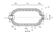
- FIG. 2 is a cross-sectional view schematically illustrating the high-pressure tank according to the first embodiment.
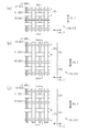
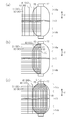
- the figure which shows typically the fiber structure in the high pressure tank of FIG. (A) is a diagram schematically showing a body sheet portion of a reinforcing fiber sheet in the first embodiment, (b) is a diagram schematically showing one dome sheet portion of the reinforcing fiber sheet, and (c) is a reinforcement thereof.
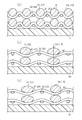
- 3A is a sectional view taken along the line 4a-4a in FIG. 3A
- FIG. 3B is a sectional view taken along the line 4b-4b in FIG. 3B
- FIG. Sectional drawing along line 4c-4c is a sectional drawing along line 4c-4c.
- (A) is a diagram schematically showing a state in which wefts are inserted in the first embodiment
- (b) is a diagram schematically showing a state after a beating operation in the first embodiment
- (c) is a first embodiment.
- (A) is a diagram schematically showing a body sheet portion of a reinforcing fiber sheet in the second embodiment
- (b) is a diagram schematically showing one dome sheet portion of the reinforcing fiber sheet
- (c) is a reinforcement thereof.
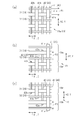
- (A) The figure which shows typically the state which inserted the weft in 2nd Embodiment, (b) The figure which shows typically the state after a beating operation in 2nd Embodiment, (c) is 2nd execution The figure which shows typically the state which wound the reinforcing fiber sheet around the liner in the form.
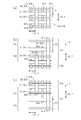
- (A) is a diagram schematically showing a body sheet portion of a reinforcing fiber sheet according to the third embodiment, (b) is a diagram schematically showing one dome sheet portion of the reinforcing fiber sheet, and (c) is a reinforcement thereof.
- (A) is a diagram schematically showing a state in which wefts are inserted in the third embodiment
- (b) is a diagram schematically showing a state after a beating operation in the third embodiment
- (c) is a third embodiment.
- the figure which shows typically the state which wound the reinforcing fiber sheet around the liner in the form.
- a high-pressure tank 10 as a pressure vessel is obtained by impregnating a fibrous structure 21 having an elongated hollow liner 12 and a reinforcing fiber sheet 19 covering the outside of the liner 12 with a matrix resin Ma. It is configured.
- the fiber-reinforced composite material layer 11 composed of the reinforcing fiber sheet 19 impregnated with the matrix resin Ma reinforces the liner 12 and secures the pressure resistance (mechanical strength) of the high-pressure tank 10.
- the liner 12 is made of resin.
- the direction in which the center axis L of the liner 12 extends is defined as the axial direction Y of the liner.
- the liner 12 includes a cylindrical body 13.
- the central axis of the body 13 coincides with the central axis L of the liner 12.
- the axial direction of the body 13 matches the axial direction Y of the liner 12.
- the liner 12 has curved dome portions 14a and 14b at both ends in the axial direction of the body portion 13. In the dome portions 14a and 14b, the diameter of the end portion adjacent to the body portion 13 is the same as the diameter of the body portion 13, and the farther away from the body portion 13, the smaller the diameter.
- the axial direction of the dome portions 14a and 14b matches the axial direction Y of the liner 12.
- the liner 12 includes a base portion 15 that protrudes outward from the dome portions 14a and 14b along the axial direction Y of the liner 12.
- Each base 15 is made of metal, for example, stainless steel.
- Each base 15 includes a hole 16 communicating with a space in the liner 12.
- a screw 18 is screwed into the hole 16 of the first base 15 extending from the dome 14 a at one end in the axial direction Y of the liner 12.
- a valve 17 is mounted on the hole 16 of the second base 15 extending from the dome 14 b on the other end in the axial direction Y of the liner 12.
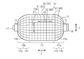
- the reinforcing fiber sheet 19 is a long woven fabric 50 formed by plain weaving a plurality of warps 30 and a plurality of wefts 40.
- the reinforcing fiber sheet 19 is wound around the outer peripheral surface of the liner 12 such that the longitudinal direction of the reinforcing fiber sheet 19 coincides with the circumferential direction Z of the liner 12.
- the warp yarns 30 and the weft yarns 40 are arranged orthogonal to each other.
- the plurality of warps 30 are arranged in the body direction 13 and the dome portions 14a and 14b in the axial direction Y of the liner 12 in a state of being parallel to each other.
- the main axis of each warp 30 extends in the circumferential direction Z of the liner 12.
- the direction in which the main axis of each warp 30 extends, that is, the main axis direction of the warp 30 is indicated by a symbol “X1”.
- the radial direction of the liner 12 is orthogonal to the main axis direction X1 of the warp 30.
- the plurality of wefts 40 are arranged in the circumferential direction Z of the liner 12 on the body 13 and the dome portions 14a and 14b in a state of being parallel to each other.
- the main axis of the portion arranged on the body 13 extends in the axial direction of the body 13.
- the yarn main axis of the portion arranged in the dome portions 14a and 14b extends in the axial direction Y of the liner 12, while being curved along the curved surfaces of the dome portions 14a and 14b.
- the direction in which the main axis of the weft 40 extends, that is, the main axis direction of the weft yarn 40 is indicated by a symbol “X2”.
- the warps 30 and the wefts 40 are arranged orthogonally, and the main axis direction X1 of the warps 30 matches the circumferential direction Z of the liner 12, thereby reinforcing the liner 12 in the radial direction of the liner 12.
- the liner 12 is reinforced in the axial direction Y of the liner 12 by matching the main axis direction X2 of the weft 40 with the axial direction Y of the liner 12.
- the warp 30 includes a plurality of first reinforcing fibers 31 and a plurality of first auxiliary yarns 32.
- the first reinforcing fibers 31 and the first auxiliary yarns 32 are alternately arranged so as to be adjacent to each other in the axial direction Y of the liner 12.
- the first reinforcing fibers 31 are arranged in parallel with each other, the first auxiliary yarns 32 are arranged in parallel with each other, and the first reinforcing fibers 31 and the first auxiliary yarns 32 are arranged in parallel with each other.
- the weft 40 includes a plurality of second reinforcing fibers 41 and a plurality of second auxiliary yarns 42.
- the second reinforcing fibers 41 and the second auxiliary yarns 42 are alternately arranged so as to be adjacent to each other in the circumferential direction Z of the liner 12.
- the second reinforcing fibers 41 are arranged in parallel with each other, the second auxiliary yarns 42 are arranged in parallel with each other, and the second reinforcing fibers 41 and the second auxiliary yarns 42 are arranged in parallel with each other.
- the first reinforcing fiber 31 and the first auxiliary yarn 32 correspond to a first yarn, and the second reinforcing fiber 41 and the second auxiliary yarn 42 correspond to a second yarn.
- the first reinforcing fibers 31, the second reinforcing fibers 41, the first auxiliary yarns 32, and the second auxiliary yarns 42 are formed from carbon fibers.
- the first reinforcing fibers 31, the second reinforcing fibers 41, the first auxiliary yarns 32, and the second auxiliary yarns 42 are not limited to carbon fibers, but may be glass fibers, silicon carbide ceramic fibers, aramid fibers, or ultrahigh molecular weight. It may be formed from other fibers generally called high elasticity and high strength, such as polyethylene fibers.
- the first reinforcing fibers 31 and the second reinforcing fibers 41 are the same fibers.
- the first auxiliary yarn 32 and the second auxiliary yarn 42 are formed of a fiber bundle thinner than the first reinforcing fibers 31 and the second reinforcing fibers 41.
- the body 13 of the liner 12 is covered with a body sheet 19m which is a part of the reinforcing fiber sheet 19.
- the dome portion 14 a of the liner 12 is covered by a dome sheet portion 19 a which is a part of the reinforcing fiber sheet 19.
- the dome portion 14b of the liner 12 is covered by a dome sheet portion 19b which is a part of the reinforcing fiber sheet 19.
- the arrangement pitch between adjacent first reinforcing fibers 31 and first auxiliary yarns 32 is P1.
- the arrangement pitch is a distance between the central axes of adjacent yarns.
- the arrangement pitch P1 is constant.
- the arrangement pitch P2 between the adjacent first reinforcing fibers 31 and the first auxiliary yarns 32 is larger than the arrangement pitch P1.
- the arrangement pitch P3 between the adjacent first reinforcing fibers 31 and the first auxiliary yarns 32 is larger than the arrangement pitch P1.
- the total number N of the first reinforcing fibers 31 and the first auxiliary yarns 32 existing per unit length in the axial direction Y of the liner 12 is:
- the dome seat portions 19a and 19b are smaller than the body seat portion 19m.
- the arrangement pitches P2 and P3 are smaller at positions closer to the body 13 in the axial direction of the dome portions 14a and 14b.
- a portion of the dome portion 14a that is separated from the body portion 13 in the axial direction Y of the liner 12 is a first dome portion 14c, and the axial direction Y of the liner 12 is ,
- a portion closer to the body portion 13 (the left portion of the dome portion 14a in FIG. 2) is referred to as a second dome portion 14d.
- the portion of the dome portion 14b that is separated from the body portion 13 in the axial direction Y of the liner 12 (the left portion of the dome portion 14b in FIG.
- first dome portion 14e is a first dome portion 14e, and the body portion in the axial direction Y of the liner 12.
- the portion closer to 13 is a second dome portion 14f.
- a portion of the dome sheet portion 19a that covers the first dome portion 14c is a first seat portion 19c
- a portion of the dome sheet portion 19b that covers the first dome portion 14e is the first seat portion 19e.
- the lower part in FIG. 3C is the first seat portion 19e.
- a portion of the dome sheet portion 19a that covers the second dome portion 14d is a lower portion in FIG.
- the arrangement pitch P2 in the second seat portion 19d is smaller than the arrangement pitch P2 in the first seat portion 19c.
- the arrangement pitch P3 in the second seat portion 19f is smaller than the arrangement pitch P3 in the first seat portion 19e.
- the first reinforcing fibers 31 and the first auxiliary yarns 32 arranged in the body sheet portion 19m have a relatively large thickness and a narrow shape.
- the first reinforcing fibers 31 and the first auxiliary yarns 32 arranged in each of the dome sheet portions 19a and 19b are flat, and the body sheet portion is provided.
- the thickness is smaller and wider than the first reinforcing fibers 31 and the first auxiliary yarns 32 arranged at 19 m.
- the thickness W2 of the dome sheet portion 19a and the thickness W3 of the dome sheet portion 19b are smaller than the thickness W1 of the body sheet portion 19m.
- the dome sheet portions 19a and 19b are separated from the body 13 in the axial direction of the dome portions 14a and 14b (the right side in FIG. 4B).
- the first reinforcing fibers 31 and the first auxiliary yarns 32 arranged in the area (the area on the left side in FIG. 4C) have a smaller thickness and a wider shape.
- the thicknesses W2 and W3 of the dome seat portions 19a and 19b are smaller at positions farther from the body 13 in the axial direction of the dome portions 14a and 14b.
- the fabric 50 is wound around the liner 12 while weaving the fabric 50 by performing plain weaving using the warp yarn 30 and the weft yarn 40.
- the plain weaving loom includes, for example, a reinforcing fiber heald frame 33 for opening the first reinforcing fiber 31 as the warp 30 and an auxiliary yarn heald frame 34 for opening the first auxiliary yarn 32 as the warp 30.
- the plain weaving loom has a warp beam 35 for supplying the first reinforcing fibers 31 and a warp beam 36 for supplying the first auxiliary yarn 32.
- An opening operation is performed on the first reinforcing fibers 31 sent out from the warp beam 35 by the reinforcing fiber heald frame 33.
- the opening operation is performed on the first auxiliary yarn 32 sent out from the warp beam 36 by the auxiliary yarn heald frame 34.
- the eyes of the reinforcing fiber heald frame 33 and the auxiliary yarn heald frame 34 are indicated by black circles in FIG.
- the reed 39 is arranged between the heald frames 33 and 34 and the weave 45.
- the reed 39 is a member that extends linearly in the axial direction Y of the liner 12 (the direction perpendicular to the plane of FIG. 5).
- the second reinforcing fiber 41 and the second auxiliary yarn 42 as the weft 40 are inserted (inserted) into the openings of the first reinforcing fiber 31 and the first auxiliary yarn 32 by a weft insertion mechanism (not shown). It has become.
- the liner 12 In the sending direction of the first reinforcing fibers 31 and the first auxiliary yarns 32, the liner 12 is rotatably supported at a position after the weave 45 before the weaving. The liner 12 rotates about a central axis L.
- the ends of the plurality of first reinforcing fibers 31 drawn out from the warp beam 35 and the plurality of first auxiliary yarns 32 drawn out from the warp beam 36. Is fixed to the outer peripheral surface of the liner 12 by, for example, an adhesive.
- the first reinforcing fibers 31 and the first auxiliary yarns 32 are arranged such that their ends are arranged on the body portion 13 and the dome portions 14a and 14b along the axial direction Y of the liner 12, and the warp beam 35. , 36 and the liner 12.
- the first reinforcing fibers 31 and the first auxiliary yarns 32 are alternately arranged in the axial direction Y of the liner 12.
- the adhesive a material that is melted by heating when impregnating and curing the matrix resin Ma in the reinforcing fiber sheet 19 can be used, but an adhesive that does not melt may be used.
- the arrangement pitch between the first reinforcing fibers 31 and the first auxiliary yarns 32 adjacent in the axial direction Y of the liner 12 is smaller than the arrangement pitch in the arrangement portion on the body 13.
- the first reinforcing fibers 31 and the first auxiliary yarns 32 are arranged such that the arrangement pitch in the arrangement portion to the dome portions 14a and 14b becomes large. Further, the first reinforcing fibers 31 and the first auxiliary yarns 32 are arranged such that the arrangement pitch in the arrangement portion to the dome portions 14a and 14b becomes larger at a position away from the body portion 13 in the axial direction of the dome portions 14a and 14b. Are arranged.
- the reinforcing fiber heald frame 33 and the auxiliary yarn heald frame 34 are alternately moved in the up and down direction without rotating the liner 12, thereby strengthening.
- the fiber heald frame 33 and the auxiliary yarn heald frame 34 are moved in opposite directions.
- the warp opening 30a is formed by the first reinforcing fibers 31 and the first auxiliary yarns 32.
- the warp openings 30a are formed each time.
- the second reinforcing fibers 41 and the second auxiliary yarns 42 are alternately inserted (inserted) into the warp openings 30a.
- the beating of the reed 39 is performed.
- the operation is performed.
- the second reinforcing fibers 41 and the second auxiliary yarns 42 are moved toward the ends of the first reinforcing fibers 31 and the first auxiliary yarns 32 fixed to the outer peripheral surface of the liner 12.
- the reinforcing fiber heald frame 33 and the auxiliary yarn heald frame 34 are moved in the opposite directions to change the opening state, and the next weft insertion operation is performed.
- the reinforcing fiber sheet 19 in which the warp 30 (the first reinforcing fiber 31 and the first auxiliary yarn 32) and the weft 40 (the second reinforcing fiber 41 and the second auxiliary yarn 42) are plain-woven is formed. Weaved. In addition to the weaving of the reinforcing fiber sheet 19, the reinforcing fiber sheet 19 is integrated with the liner 12.
- the woven fabric 50 is wound around the liner 12 by rotating the liner 12 around the central axis L. While winding the fabric 50 around the liner 12, the weaving of the fabric 50 is performed in the same manner as described above. As a result, the fabric 50, that is, the reinforcing fiber sheet 19, is wound around the liner 12 so as to cover the entire dome portions 14 a and 14 b and the body portion 13. Thereby, the fibrous structure 21 including the reinforcing fiber sheet 19 on the outer peripheral surface of the liner 12 is manufactured.
- the fiber-reinforced composite material layer 11 is formed by impregnating and hardening the matrix fiber Ma into the reinforcing fiber sheet 19, and the high-pressure tank 10 in which the outside of the liner 12 is covered with the fiber-reinforced composite material layer 11 is manufactured.
- the impregnation and curing of the matrix resin Ma are performed by, for example, an RTM (resin transfer molding) method.
- the operation of the high-pressure tank 10 will be described.
- the dome sheet portions 19a and 19b in which the arrangement pitch between the adjacent first reinforcing fibers 31 and the first auxiliary yarns 32 is relatively large when the reinforcing fiber sheet 19 is wound around the outer peripheral surface of the liner 12, the shape of the liner 12 is changed. Accordingly, the first reinforcing fibers 31 and the first auxiliary yarns 32 move easily. For this reason, the dome sheet portions 19a and 19b easily conform to the shapes of the dome portions 14a and 14b.
- the dome portions 14a and 14b have a diameter smaller than the diameter of the body 13 at a position farther from the body 13 in the axial direction. For this reason, the dome portions 14a and 14b have a shape that curves farther away from the body portion 13 in a position farther from the body portion 13 in the axial direction.
- the arrangement pitches P2 and P3 are larger at locations farther from the body portion 13 in the axial direction. For this reason, the arranged first reinforcing fibers 31 and first auxiliary yarns 32 are more easily moved in the dome portions 14a and 14b as the degree of curvature is larger. Therefore, the portions of the dome sheet portions 19a and 19b that cover the portions of the dome portions 14a and 14b with a large degree of curvature are more likely to follow the shapes of the dome portions 14a and 14b.
- the dome portions 14a and 14b to which the base portion 15 is connected have a shape protruding outward along the axial direction Y of the liner 12, the dome portions 14a and 14b are easily deformed by internal pressure.
- the thicknesses W2 and W3 of the dome sheet portions 19a and 19b are smaller than the thickness W1 of the body sheet portion 19m, the dome sheet portions 19a and 19b are hardly deformed.
- the internal pressure generated in the dome portions 14 a and 14 b is smaller than the internal pressure generated in the body 13. Therefore, even if the thickness of the dome sheet portions 19a and 19b is not as large as the thickness of the body sheet portion 19m, it is possible to realize the reinforcing fiber sheet 19 having appropriate pressure resistance.
- the thicknesses W2 and W3 of the dome sheet portions 19a and 19b are made smaller than the thickness W1 of the body sheet portion 19m. Of the thicknesses W2 and W3 of the first embodiment can be suppressed.
- the arrangement pitches P2 and P3 of the first reinforcing fibers 31 and the first auxiliary yarns 32 adjacent to each other in the dome portions 14a and 14b are determined by the first reinforcing fibers 31 and the first auxiliary yarns 32 adjacent to each other in the body portion 13. Is larger than the arrangement pitch P1.
- the total number N of the warp yarns 30 (the first reinforcing fibers 31 and the first auxiliary yarns 32) existing per unit length in the axial direction Y of the liner 12 is smaller in the dome portions 14a and 14b than in the body portion 13.
- the dome sheet portions 19a and 19b can be appropriately arranged along the shape of the dome portions 14a and 14b. Therefore, wrinkles in the dome sheet portions 19a and 19b can be suppressed, and the pressure resistance of the high-pressure tank 10 can be improved.
- the arrangement pitches P2 and P3 are smaller at positions closer to the body portion 13 in the axial direction of the dome portions 14a and 14b. For this reason, the dome sheet portions 19a and 19b can more appropriately conform to the shapes of the dome portions 14a and 14b as compared with the case where the arrangement pitches P2 and P3 are constant throughout the dome portions 14a and 14b. Therefore, wrinkles in the dome sheet portions 19a and 19b can be further suppressed, and the pressure resistance of the high-pressure tank 10 can be further improved.
- the second embodiment will be described with reference to FIGS. 7A to 8C, focusing on differences from the first embodiment.
- the warp 30 (the first reinforcing fiber 31 and the first auxiliary fiber 31) in each of the dome portions 14a and 14b.
- the arrangement pitches P2 and P3 of the yarn 32) are constant and the same as the arrangement pitch P1 of the warp yarns 30 in the body 13.
- the arrangement of the wefts 40 (the second reinforcing fibers 41 and the second auxiliary yarns 42) is different from that of the first embodiment.
- the second embodiment is the same as the first embodiment.
- the weft 40 (the second reinforcing fiber 41 and the second auxiliary yarn 42) is moved in the axial direction Y of the liner 12 (see FIG. 7A to 7C, the extending range in the vertical direction is changed in the circumferential direction Z of the liner 12 (the horizontal direction in FIGS. 7A to 7C). More specifically, a plurality of (four in the present embodiment) adjacent wefts 40 are arranged such that the extending range in the axial direction Y of the liner 12 decreases in the circumferential direction Z of the liner 12 in order.
- the four wefts 40 arranged such that the extension range in the axial direction Y of the liner 12 decreases in the circumferential direction Z of the liner 12 in order from the one in which the extension range in the axial direction Y of the liner 12 is large.
- the second reinforcing fiber 41a, the second auxiliary yarn 42a, the second reinforcing fiber 41b, and the second auxiliary yarn 42b are set in this order.
- the second reinforcing fiber 41a extends in the axial direction Y of the liner 12 over the entire body 13 and the entire dome portions 14a and 14b.
- the second auxiliary yarn 42a and the second reinforcing fiber 41b extend in the axial direction Y of the liner 12 over the entire body 13 and a part of each of the dome portions 14a and 14b.
- the range in which the second auxiliary thread 42a extends to the dome portions 14a, 14b is larger than that of the second reinforcing fiber 41b.
- the second auxiliary thread 42b extends throughout the body 13 in the axial direction Y of the liner 12, but does not extend to the domes 14a and 14b.
- Such an arrangement of the second reinforcing fibers 41a, the second auxiliary yarns 42a, the second reinforcing fibers 41b, and the second auxiliary yarns 42b is repeated in the circumferential direction Z of the liner 12.
- the wefts 40 (the second reinforcing fibers 41 and the second reinforcing fibers 41) existing per unit length in the axial direction Y of the liner 12 are provided.
- the total number N of the 2 auxiliary yarns 42) is smaller in the dome sheet portions 19a and 19b than in the body sheet portion 19m.
- the thickness of the dome sheet portions 19a and 19b is smaller than the thickness of the body sheet portion 19m.
- the total number N of the wefts 40 (the second reinforcing fibers 41 and the second auxiliary yarns 42) present per unit length in the axial direction Y of the liner 12 in the dome portions 14a and 14b is a position apart from the body portion 13. It is getting less. As a result, the thickness of the dome seat portions 19a and 19b decreases as the distance from the body seat portion 19m increases.
- the second reinforcing fibers 41a are long yarns extending in the axial direction Y of the liner 12 over the entire body 13 and the entire dome portions 14a and 14b.
- the second auxiliary yarn 42b is a short yarn that extends over the entire body 13 in the axial direction Y of the liner 12 and does not extend to the dome portions 14a and 14b.
- the second auxiliary yarn 42a and the second reinforcing fiber 41b are intermediate yarns extending in the axial direction Y of the liner 12 over the entire body 13 and a part of the dome portions 14a and 14b.
- the second auxiliary yarn 42a, the second reinforcing fiber 41b, and the second auxiliary yarn 42b extend over the entire body 13 in the axial direction Y of the liner 12, and the second auxiliary fiber 41a ( The short yarn extends in a range smaller than the long yarn.
- the second auxiliary yarn 42a is a first short yarn extending over the entire body 13 and a part of the dome portions 14a and 14b in the axial direction Y of the liner 12, and includes the second reinforcing fiber 41b and the second auxiliary yarn.
- the yarn 42b is a second short yarn extending in a range smaller than the second auxiliary yarn 42a (first short yarn) in the axial direction Y of the liner 12.
- the weaving of the woven fabric 50 is performed using the plain weaving machine shown in FIG. That is, the ends of the plurality of first reinforcing fibers 31 drawn from the warp beam 35 and the ends of the plurality of first auxiliary yarns 32 drawn from the warp beam 36 are fixed to the outer peripheral surface of the liner 12. Is done. As shown in FIG. 8A, the first reinforcing fibers 31 and the first auxiliary yarns 32 are alternately arranged in the axial direction Y of the liner 12, but unlike the first embodiment, adjacent first reinforcing fibers 31. The arrangement pitch between the first auxiliary yarn 32 and the first auxiliary yarn 32 is constant over the entire axial direction Y of the liner 12.
- the warp openings 30a are formed by the movement of the reinforcing fiber heald frame 33 and the auxiliary yarn heald frames 34 while the liner 12 is not rotated, and the warp openings 30a are formed.
- the second reinforcing fibers 41 and the second auxiliary yarns 42 are alternately weft-inserted (inserted) into the warp openings 30a.
- the liner 12 is moved in the axial direction Y.
- the range of weft insertion is changed. Specifically, the weft insertion of the second reinforcing fiber 41a is performed in the axial direction Y of the liner 12 over the entire body 13 and the entire dome portions 14a and 14b.
- the range in which weft insertion of the second reinforcing fibers 41a is performed corresponds to the long yarn range.
- the weft insertion of the second auxiliary thread 42a is performed in the axial direction Y of the liner 12 over the entire body 13 and a part of each of the dome parts 14a and 14b.
- the weft insertion of the second reinforcing fiber 41b is performed in the axial direction Y of the liner 12 over the entire body 13 and a part of each of the dome portions 14a and 14b. However, the range of weft insertion over a part of each dome portion 14a, 14b is smaller in the second reinforcing fiber 41b than in the second auxiliary yarn 42a.
- the weft insertion of the second auxiliary thread 42b is performed in the axial direction Y of the liner 12 in a range over the entire body 13 but not in a range corresponding to the dome portions 14a and 14b.
- the range where the weft insertion of the second auxiliary yarn 42a is performed corresponds to the short yarn range. Weft insertion is repeatedly performed in the order of the second reinforcing fiber 41a, the second auxiliary yarn 42a, the second reinforcing fiber 41b, and the second auxiliary yarn 42b.
- the second reinforcing fibers 41 (the second reinforcing fibers 41a and the second reinforcing fibers 41b) and the second auxiliary yarns 42 (the second auxiliary yarns 42a and 42b) are arranged in the axial direction Y of the liner 12.
- the length is set so that weft insertion can be performed over the entire length of the warp shed 30a formed by all the first reinforcing fibers 31 and the first auxiliary yarns 32. Therefore, both ends of the second auxiliary yarn 42a, the second reinforcing fiber 41b, and the second auxiliary yarn 42b are not inserted into the warp shed 30a.
- the length of the portion where the weft is not inserted increases in the order of the second auxiliary yarn 42a, the second reinforcing fiber 41b, and the second auxiliary yarn 42b.
- the non-wefted portions extend along the surface of the reinforcing fiber sheet 19, respectively.
- the portion of the second reinforcing fiber 41 and the second auxiliary yarn 42 which are not inserted into the weft are removed from the fabric 50 by cutting or the like. It is.
- the high-pressure tank 10 in which the outside of the liner 12 is covered with the fiber-reinforced composite material layer 11 is manufactured by impregnating the matrix resin Ma into the reinforcing fiber sheet 19 and curing. You.
- the dome sheet portions 19a and 19b in which the number of the arranged wefts 40 is relatively small, when the reinforcing fiber sheet 19 is wound around the outer peripheral surface of the liner 12, the wefts 40 (the second reinforcing fibers 41) are formed according to the shape of the liner 12. And the second auxiliary thread 42) is easy to move. For this reason, the dome sheet portions 19a and 19b easily conform to the shapes of the dome portions 14a and 14b.
- the total number N of the weft yarns 40 decreases as the distance from the body portion 13 in the axial direction Y decreases. Therefore, the wefts 40 arranged in the dome portions 14a and 14b are more likely to move as the degree of curvature is greater. Therefore, the portions of the dome sheet portions 19a and 19b that cover the portions of the dome portions 14a and 14b with a large degree of curvature are more likely to follow the shapes of the dome portions 14a and 14b.
- the main axis direction X1 of the first reinforcing fibers 31 and the first auxiliary yarns 32 matches the circumferential direction Z of the liner 12. Therefore, the main axis direction X1 of the first reinforcing fibers 31 and the first auxiliary yarns 32 arranged in the dome portions 14a and 14b can be easily set to a direction suitable for the pressure resistance of the high-pressure tank 10.
- the second auxiliary thread 42b is not arranged on the dome sheet portions 19a and 19b.
- the total number N of the second reinforcing fibers 41 and the second auxiliary yarns 42 to be arranged is smaller in the domes 14a and 14b than in the body 13 by the amount of the second auxiliary yarns 42b.
- the dome sheet portions 19a and 19b can be appropriately arranged along the shape of the dome portions 14a and 14b. Therefore, wrinkles in the dome sheet portions 19a and 19b can be suppressed, and the pressure resistance of the high-pressure tank 10 can be improved.
- the weft 40 includes the second auxiliary yarn 42a and the second reinforcing fiber 41b which extend in the axial direction Y of the liner 12 over the entire body 13 and a part of each of the dome portions 14a, 14b.
- the second auxiliary yarn 42a and the second reinforcing fiber 41b extend in ranges different from each other in the axial direction Y of the liner 12 in each of the dome portions 14a and 14b. Therefore, as compared with the case where the weft 40 does not include the second auxiliary yarn 42a and the second reinforcing fiber 41b, the dome sheet portions 19a and 19b can more appropriately follow the shape of the dome portions 14a and 14b. it can. Therefore, generation of wrinkles in the dome sheet portions 19a and 19b can be further suppressed, and the pressure resistance of the high-pressure tank 10 can be further improved.
- the third embodiment is a combination of the first embodiment and the second embodiment, as shown in FIGS. 9A, 9B, and 9C. That is, in the third embodiment, the arrangement pitch of the warp yarns 30 (the first reinforcing fibers 31 and the first auxiliary yarns 32) is different between the body portion 13 and the dome portions 14a and 14b as in the first embodiment. At the same time, as in the second embodiment, the extending range of the weft 40 (the second reinforcing fiber 41 and the second auxiliary yarn 42) changes in the circumferential direction Z of the liner 12.
- FIGS. 10A, 10B, and 10C show a method of manufacturing the high-pressure tank 10 according to the third embodiment.
- the warp yarns 30 are arranged such that the arrangement pitch of the dome portions 14a and 14b is larger than the arrangement pitch of the body portions 13 in the arrangement pitch of the warp yarns 30. You. Then, similarly to the second embodiment, each time weft insertion of the weft yarn 40 is performed, the range of the weft insertion in the axial direction Y of the liner 12 is changed.
- the second auxiliary yarn 42 may be used as the yarn extending over the entire body 13 and the entire dome portions 14a and 14b in the axial direction Y of the liner 12.
- the second auxiliary yarn 42, the second reinforcing fiber 41, the second auxiliary yarn 42, and the second reinforcing fiber 41 are arranged such that the extending range in the axial direction Y of the liner 12 is reduced in this order.
- the two reinforcing fibers 41 and the second auxiliary yarns 42 are arranged in the circumferential direction Z of the liner 12.
- the weft 40 having a relatively large extension range in the axial direction Y of the liner 12 and the weft 40 having a relatively small extension range in the axial direction Y of the liner 12 are provided. May be alternately arranged in the circumferential direction Z.
- the second reinforcing fibers 41 are arranged such that two or more wefts 40 having the same size and extending in the axial direction Y of the liner 12 are continuously arranged in the circumferential direction Z of the liner 12.
- the second auxiliary thread 42 may be arranged.
- the size of the range in which the weft 40 extends in the axial direction Y of the liner 12 may change in five or more steps, or may change in three or less steps.
- the weft 40 extends in the axial direction Y of the liner 12 over the entire body 13 and the entire dome portions 14a and 14b, and extends over the entire body 13 and the dome portions 14a and 14a. And at least a short thread that does not extend over part or all of 14b.
- the arrangement pitch of the warp yarns 30 adjacent in the dome portions 14a and 14b may be changed stepwise in the axial direction Y of the liner 12.
- at least three warps 30 are arranged at the same arrangement pitch in the dome portions 14a and 14b, and the arrangement pitch is reduced in the axial direction Y of the liner 12 as it approaches the body portion 13.
- the size of the arrangement pitch of the warps 30 adjacent to each other in the dome portions 14a and 14b does not have to be changed in order in the axial direction Y of the liner 12.
- the arrangement pitch of the warps 30 adjacent to each other in the dome portions 14a and 14b may be such that a relatively large arrangement pitch and a relatively small arrangement pitch are alternately arranged in the axial direction Y of the liner 12.
- the combination and change of the arrangement pitch of the warp yarns 30 may be different between the dome portion 14a and the dome portion 14b.
- the arrangement pitch of the warps 30 adjacent to each other in the dome portions 14a and 14b may be constant throughout the dome portions 14a and 14b.
- the arrangement pitch of the warp yarns 30 may be the same or different between the dome portion 14a and the dome portion 14b.
- the reinforcing fiber sheet 19 is formed by laminating a fiber layer formed by the first reinforcing fibers 31 and the first auxiliary yarns 32 and a fiber layer formed by the second reinforcing fibers 41 and the second auxiliary yarns 42. May be made of a multi-layer woven fabric in which the fiber layers are constrained in the laminating direction by constraining yarns.
- the woven fabric 50 may be woven using a fiber base material impregnated with a resin in advance.
- the liner 12 may have a shape in which a dome portion is continuous with one end in the axial direction Y of the body portion 13 and a flat end wall is continuous with the other end in the axial direction Y of the body portion 13. In this case, the base part 15 exists only at one end side where the dome part exists.
- the entire liner 12 may be formed of an aluminum alloy instead of aluminum, or the base 15 may be formed of a metal different from stainless steel.
- the high-pressure tank 10 is not limited to being used as a hydrogen tank for an electric vehicle equipped with a fuel cell, but may be used for a hydrogen tank for a hydrogen engine, or may be applied to a heat pump or the like. Further, it may be used as a hydrogen tank for a fuel cell of a home power supply.
- the present invention is not limited to the high-pressure tank for storing hydrogen, and may be applied to a pressure vessel for storing a gas other than hydrogen, such as nitrogen and compressed natural gas.
Landscapes
- Engineering & Computer Science (AREA)
- Mechanical Engineering (AREA)
- General Engineering & Computer Science (AREA)
- Manufacturing & Machinery (AREA)
- Chemical & Material Sciences (AREA)
- Composite Materials (AREA)
- Textile Engineering (AREA)
- Woven Fabrics (AREA)
- Moulding By Coating Moulds (AREA)
- Filling Or Discharging Of Gas Storage Vessels (AREA)
Abstract
圧力容器は、円筒状の胴体部、及び、胴体部の軸方向の少なくとも一端に連続するドーム部、を有するライナと、ライナを外側から覆う織物製の強化繊維シートと、を備える。強化繊維シートは、ライナの周方向へ糸主軸が延びるように胴体部及びドーム部に配列された第1の糸と、ライナの軸方向へ糸主軸が延びるように胴体部及びドーム部に配列された第2の糸と、を備える。ライナの軸方向における単位長さ当たりに存在する第1の糸又は第2の糸の合計本数が、ドーム部では胴体部よりも少ない。
Description
本開示は、圧力容器及び圧力容器の製造方法に関する。
圧縮天然ガス(CNG)、液化天然ガス(LNG)等のガスを収容する圧力容器、所謂、高圧タンクは、一般にスチールやアルミニウム合金等の金属製のため重量が重い。近年、天然ガスを燃料として用いる自動車が低公害車として注目されており、より低公害のものとして、燃料電池を動力源とする自動車も注目されている。燃料電池の燃料として水素ガスを燃料タンクに収容する自動車もあるが、燃料タンクに用いられる圧力容器の重量が重く燃費が悪くなる。この不都合を解消するため、ガスバリア性を有するライナの外側を、耐圧性を有する繊維強化複合材層で覆った圧力容器が提案されている。繊維強化複合材層によりライナが補強されているので、圧力容器内には数十MPaの圧力を有するガスを充填することができる。
圧力容器のライナは、一般に、円筒状の胴体部と、胴体部の軸方向の少なくとも一端に連続するドーム部と、を有する。例えば、特許文献1に開示される圧力容器では、胴体部及びドーム部の外周面に1枚の強化繊維シートが複数回巻き付けられる。その後、フィラメントワインディング法によって胴体部及びドーム部に対し連続繊維のヘリカル巻きが行われる。
特許文献2に開示された圧力容器では、同圧力容器に巻き付けられる強化繊維シートは、ライナの周方向へ糸主軸が延びるように胴体部に配列された第1の糸と、胴体部の軸方向及び前記ドーム部の軸方向へ糸主軸が延びるように胴体部及びドーム部に配列された第2の糸と、を備える。第1の糸はドーム部に配置されておらず、第2の糸のみがドーム部に配列されている。圧力容器への強化繊維シートの巻き付け後、樹脂が含浸された連続繊維がフープ巻きによってドーム部に巻回される。
特許文献1に開示された圧力容器においては、強化繊維シートのうちでドーム部の外周面に巻き付けられる部分にしわが生じるおそれがある。
特許文献2の圧力容器において所望の耐圧性を実現するためには、ドーム部に配列された第2の糸と直交する方向等、所定の方向に延びるように連続繊維をドーム部に巻回することが望ましい。しかしながら、ドーム部は湾曲した形状であるため、ドーム部の全体で連続繊維の延在方向を適正に維持しつつ巻回を行うことは困難である。
特許文献2の圧力容器において所望の耐圧性を実現するためには、ドーム部に配列された第2の糸と直交する方向等、所定の方向に延びるように連続繊維をドーム部に巻回することが望ましい。しかしながら、ドーム部は湾曲した形状であるため、ドーム部の全体で連続繊維の延在方向を適正に維持しつつ巻回を行うことは困難である。
本開示の目的は、ドーム部の周りに強化繊維シートを適切に配置することができる圧力容器及び圧力容器の製造方法を提供することにある。
本開示の一態様に係る圧力容器は、円筒状の胴体部、及び、前記胴体部の軸方向の少なくとも一端に連続するドーム部、を有するライナと、前記ライナの周方向に沿って前記ライナの外周面に巻き付けられるとともに前記ライナを外側から覆う織物製の強化繊維シートと、を備える。前記強化繊維シートは、前記ライナの周方向へ糸主軸が延びるように前記胴体部及び前記ドーム部に配列された第1の糸と、前記ライナの軸方向へ糸主軸が延びるように前記胴体部及び前記ドーム部に配列された第2の糸と、を備える。前記ライナの軸方向における単位長さ当たりに存在する前記第1の糸又は前記第2の糸の合計本数が、前記ドーム部では前記胴体部よりも少ない。
本開示の一態様に係る圧力容器の製造方法は、円筒状の胴体部、及び、前記胴体部の軸方向の少なくとも一端に連続するドーム部、を有するライナを準備することと、織物製の強化繊維シートで前記ライナを外側から覆うことと、を備える。前記強化繊維シートで前記ライナを外側から覆うことは、前記ライナから該ライナの軸方向に直交する方向に延びる複数の第1の糸を、前記胴体部及び前記ドーム部に亘って前記ライナの軸方向に配列すること、前記ライナの軸方向に隣り合う前記第1の糸の間に形成された開口に、前記ライナの軸方向に延びる前記第2の糸を挿入することと、前記第2の糸を筬打ち動作で前記ライナに向けて押し込むことと、を繰り返すことにより、前記強化繊維シートを製織すること、及び、前記強化繊維シートの製織と並行して前記ライナを該ライナの中心軸線の周りで回転させて、製織された前記強化繊維シートを前記ライナに巻き付けること、を含む。前記ライナの軸方向への前記第1の糸の配列、又は前記開口への前記第2の糸の挿入は、前記ライナの軸方向における単位長さ当たりに存在する前記第1の糸又は前記第2の糸の合計本数が前記ドーム部では前記胴体部よりも少なくなるように行われる。
以下、圧力容器及びその製造方法を具体化した第1実施形態について図1~図6(c)を用いて説明する。
図1に示すように、圧力容器である高圧タンク10は、細長中空状のライナ12と、ライナ12の外側を覆う強化繊維シート19と、を有する繊維構造体21にマトリックス樹脂Maを含浸させて構成されている。マトリックス樹脂Maの含浸された強化繊維シート19よりなる繊維強化複合材層11はライナ12を補強し、高圧タンク10の耐圧性(機械的強度)を確保している。
図1に示すように、圧力容器である高圧タンク10は、細長中空状のライナ12と、ライナ12の外側を覆う強化繊維シート19と、を有する繊維構造体21にマトリックス樹脂Maを含浸させて構成されている。マトリックス樹脂Maの含浸された強化繊維シート19よりなる繊維強化複合材層11はライナ12を補強し、高圧タンク10の耐圧性(機械的強度)を確保している。
ライナ12は、樹脂製である。ライナ12の中心軸線Lの延びる方向をライナの軸方向Yとする。ライナ12は、円筒状の胴体部13を備える。胴体部13の中心軸線はライナ12の中心軸線Lと一致する。そして、胴体部13の軸方向は、ライナ12の軸方向Yと一致する。ライナ12は、胴体部13の軸方向両端に、湾曲した形状のドーム部14a,14bを有する。ドーム部14a,14bにおいて、胴体部13に隣接する端部の径は胴体部13の径と同じ大きさであり、胴体部13から離れた箇所ほど径が小さくなっている。ドーム部14a,14bの軸方向は、ライナ12の軸方向Yと一致する。ライナ12は、ドーム部14a,14bからライナ12の軸方向Yに沿って外側に突出した口金部15を備える。各口金部15は金属製、例えばステンレス製である。各口金部15は、ライナ12内の空間と連通する孔部16を備える。ライナ12の軸方向Y一端側のドーム部14aから延びる第1の口金部15の孔部16には螺子18が螺合されている。ライナ12の軸方向Y他端側のドーム部14bから延びる第2の口金部15の孔部16にはバルブ17が装着されている。
図2に示すように、強化繊維シート19は、複数本の経糸30と、複数本の緯糸40とを平織りして製織された長尺状の織物50である。強化繊維シート19の長手方向がライナ12の周方向Zに一致するように、強化繊維シート19はライナ12の外周面に巻き付けられている。強化繊維シート19において、経糸30と緯糸40とは互いに直交して配列されている。複数本の経糸30は、互いに平行な状態で胴体部13及びドーム部14a,14bにライナ12の軸方向Yに配列されている。各経糸30の糸主軸は、ライナ12の周方向Zに延びている。各経糸30の糸主軸の延びる方向、すなわち糸主軸方向が符号「X1」で示されている。また、経糸30の糸主軸方向X1に対し、ライナ12の径方向が直交している。
複数本の緯糸40は、互いに平行な状態で胴体部13及びドーム部14a,14bにライナ12の周方向Zに配列されている。緯糸40のうち、胴体部13に配列される部分の糸主軸は、胴体部13の軸方向へ延びる。緯糸40のうち、ドーム部14a,14bに配列される部分の糸主軸は、ライナ12の軸方向Yへ延びる一方、ドーム部14a,14bの曲面に沿って湾曲している。緯糸40の糸主軸の延びる方向、すなわち糸主軸方向が符号「X2」で示されている。
経糸30と緯糸40とを直交して配列させるとともに、経糸30の糸主軸方向X1をライナ12の周方向Zに一致させることで、ライナ12の径方向においてライナ12を補強している。また、緯糸40の糸主軸方向X2をライナ12の軸方向Yに一致させることで、ライナ12の軸方向Yにおいてライナ12を補強している。
経糸30は、複数本の第1強化繊維31と複数本の第1補助糸32とを含む。第1強化繊維31と第1補助糸32とは、ライナ12の軸方向Yに隣り合うように交互に配列されている。また、第1強化繊維31同士は互いに平行に配列され、第1補助糸32同士は互いに平行に配列され、第1強化繊維31と第1補助糸32とは互いに平行に配列されている。
緯糸40は、複数本の第2強化繊維41と複数本の第2補助糸42とを含む。第2強化繊維41と第2補助糸42とは、ライナ12の周方向Zに隣り合うように交互に配列されている。第2強化繊維41同士は互いに平行に配列され、第2補助糸42同士は互いに平行に配列され、第2強化繊維41と第2補助糸42とは互いに平行に配列されている。第1強化繊維31及び第1補助糸32が第1の糸に相当し、第2強化繊維41及び第2補助糸42が第2の糸に相当する。
本実施形態では、第1強化繊維31、第2強化繊維41、第1補助糸32、及び第2補助糸42は炭素繊維から形成される。なお、第1強化繊維31、第2強化繊維41、第1補助糸32、及び第2補助糸42は炭素繊維に限らず、ガラス繊維、炭化ケイ素系セラミック繊維、アラミド繊維、或いは、超高分子量ポリエチレン繊維等、一般に高弾性・高強度といわれるその他の繊維から形成されてもよい。また、本実施形態では、第1強化繊維31と第2強化繊維41とは同じ繊維である。第1補助糸32及び第2補助糸42は、第1強化繊維31及び第2強化繊維41より細い繊維束からなる。
図3(a)に示すように、ライナ12の胴体部13は、強化繊維シート19の一部分である胴体シート部19mによって覆われている。図3(b)に示すように、ライナ12のドーム部14aは、強化繊維シート19の一部分であるドームシート部19aによって覆われている。図3(c)に示すように、ライナ12のドーム部14bは、強化繊維シート19の一部分であるドームシート部19bによって覆われている。
図3(a)に示すように、胴体シート部19mでは、隣り合う第1強化繊維31と第1補助糸32との配列ピッチがP1である。なお、配列ピッチは、隣り合う糸の中心軸間の距離である。ライナ12の軸方向Yにおいて、配列ピッチP1は一定である。図3(b)に示すように、ドームシート部19aでは、隣り合う第1強化繊維31と第1補助糸32との配列ピッチP2が上記配列ピッチP1よりも大きくなっている。図3(c)に示すように、ドームシート部19bでは、隣り合う第1強化繊維31と第1補助糸32との配列ピッチP3が上記配列ピッチP1よりも大きくなっている。上記のように配列ピッチP1,P2,P3が設定されていることで、ライナ12の軸方向Yにおける単位長さ当たりに存在する第1強化繊維31及び第1補助糸32の合計本数Nが、ドームシート部19a,19bでは胴体シート部19mよりも少なくなっている。
なお、図3(a)、図3(b)、及び図3(c)では、隣り合う第1強化繊維31と第1補助糸32との間や、隣り合う第2強化繊維41と第2補助糸42との間に間隙があるようにみえるが、そうした間隙は実際には存在しない。実際の強化繊維シート19においては、隣り合う第1強化繊維31と第1補助糸32とがライナ12の軸方向Yで接触するように配列されているとともに、隣り合う第2強化繊維41と第2補助糸42とがライナ12の周方向Zで接触するように配列されている。
また、ドームシート部19a,19bにおいて、ドーム部14a,14bの軸方向で胴体部13に近い箇所ほど上記配列ピッチP2,P3が小さくなっている。ここで、ドーム部14aのうち、ライナ12の軸方向Yにおいて胴体部13から離間した方の部分(図2ではドーム部14aの右側部分)を第1ドーム部14cとし、ライナ12の軸方向Yにおいて胴体部13に近い方の部分(図2ではドーム部14aの左側部分)を第2ドーム部14dとする。ドーム部14bのうち、ライナ12の軸方向Yにおいて胴体部13から離間した方の部分(図2ではドーム部14bの左側部分)を第1ドーム部14eとし、ライナ12の軸方向Yにおいて胴体部13に近い方の部分(図2ではドーム部14bの右側部分)を第2ドーム部14fとする。また、ドームシート部19aのうちで第1ドーム部14cを覆う部分(図3(b)では上側部分)を第1シート部19cとし、ドームシート部19bのうちで第1ドーム部14eを覆う部分(図3(c)では下側部分)を第1シート部19eとする。ドームシート部19aのうちで第2ドーム部14dを覆う部分(図3(b)では下側部分)を第2シート部19dとし、ドームシート部19bのうちで第2ドーム部14fを覆う部分(図3(c)では上側部分)を第2シート部19fとする。ドームシート部19aにおいては、第2シート部19dでの上記配列ピッチP2が、第1シート部19cでの上記配列ピッチP2よりも小さくなっている。ドームシート部19bにおいては、第2シート部19fでの上記配列ピッチP3が、第1シート部19eでの上記配列ピッチP3よりも小さくなっている。
図4(a)に示すように、胴体シート部19mに配列される第1強化繊維31及び第1補助糸32は、比較的厚みが大きく、幅狭な形状である。一方、図4(b)及び図4(c)に示すように、各ドームシート部19a,19bに配列される第1強化繊維31及び第1補助糸32は、扁平状であり、胴体シート部19mに配列される第1強化繊維31及び第1補助糸32よりも、厚みが小さく、幅広な形状である。これにより、強化繊維シート19においては、ドームシート部19aの厚みW2及びドームシート部19bの厚みW3が、胴体シート部19mの厚みW1よりも小さくなっている。
また、図4(b)及び図4(c)に示すように、ドームシート部19a,19bにおいて、ドーム部14a,14bの軸方向で胴体部13から離れた箇所(図4(b)では右側の箇所、図4(c)では左側の箇所)ほど、配列される第1強化繊維31及び第1補助糸32は厚みがより小さく、より幅広な形状となっている。これにより、ドームシート部19a,19bの厚みW2,W3は、ドーム部14a,14bの軸方向で胴体部13から離れた位置ほど小さくなっている。
次に、高圧タンク10の製造方法を説明する。
高圧タンク10を製造する際は、経糸30と緯糸40とを用いて平織りを行って織物50を製織しつつ、織物50をライナ12に巻き付けていく。
高圧タンク10を製造する際は、経糸30と緯糸40とを用いて平織りを行って織物50を製織しつつ、織物50をライナ12に巻き付けていく。
図5に示すように、織物50の製織は平織織機で行う。平織織機は、例えば、経糸30である第1強化繊維31の開口を行う強化繊維綜絖枠33と、経糸30である第1補助糸32の開口を行う補助糸綜絖枠34とを備える。また、平織織機は、第1強化繊維31を供給する経糸ビーム35と、第1補助糸32を供給する経糸ビーム36とを有する。経糸ビーム35から送り出される第1強化繊維31に対し、強化繊維綜絖枠33により開口操作が行われるようになっている。経糸ビーム36から送り出される第1補助糸32に対し、補助糸綜絖枠34により開口操作が行われるようになっている。なお、強化繊維綜絖枠33及び補助糸綜絖枠34の目は、図5において黒丸で示されている。
筬39は、綜絖枠33,34と織り前45との間に配置されている。筬39は、ライナ12の軸方向Y(図5では紙面に垂直方向)へ直線状に延びる部材である。緯糸40である第2強化繊維41及び第2補助糸42は、第1強化繊維31及び第1補助糸32の開口に対して緯入れ機構(図示せず)により緯入れ(挿入)されるようになっている。第1強化繊維31及び第1補助糸32の送り出し方向において、織り前45よりも後工程の位置にはライナ12が回転可能に支持されている。ライナ12は、中心軸線Lの周りで回転する。
上記の平織織機で強化繊維シート19を製織するに際しては、経糸ビーム35から引き出された複数本の第1強化繊維31の端部と、経糸ビーム36から引き出された複数本の第1補助糸32の端部と、を例えば接着剤によってライナ12の外周面に固定する。これにより、第1強化繊維31及び第1補助糸32は、それらの端部がライナ12の軸方向Yに沿って胴体部13及びドーム部14a,14b上に配列された状態で、経糸ビーム35,36とライナ12との間を延びる。第1強化繊維31及び第1補助糸32は、ライナ12の軸方向Yで交互に並んでいる。なお、接着剤は、強化繊維シート19にマトリックス樹脂Maを含浸及び硬化させる際の加熱によって溶融する材質のものを用いることができるが、溶融しない材質の接着剤を用いてもよい。
図6(a)に示すように、ライナ12の軸方向Yにおいて隣り合う第1強化繊維31と第1補助糸32との配列ピッチについて、胴体部13への配列部分での配列ピッチよりも、ドーム部14a,14bへの配列部分での配列ピッチが大きくなるように、第1強化繊維31及び第1補助糸32は配列されている。また、ドーム部14a,14bへの配列部分での配列ピッチが、ドーム部14a,14bの軸方向で胴体部13から離れた位置ほど大きくなるように、第1強化繊維31及び第1補助糸32は配列されている。
図5に示すように、強化繊維シート19を製織する際には、ライナ12を回転させない状態で、強化繊維綜絖枠33と補助糸綜絖枠34とを交互に上下方向に移動させることにより、強化繊維綜絖枠33と補助糸綜絖枠34とが逆方向に移動される。これにより、第1強化繊維31及び第1補助糸32によって経糸開口30aが形成される。第1強化繊維31と第1補助糸32とが隣接するもの同士で交互に上下に開かれることにより、その都度で経糸開口30aが形成される。経糸開口30aが形成される都度、経糸開口30aに対して第2強化繊維41と第2補助糸42とが交互に緯入れ(挿入)される。
図6(b)に示すように、経糸開口30aの形成と経糸開口30aに対する第2強化繊維41及び第2補助糸42の交互の緯入れとが所定回数行われた後、筬39の筬打ち動作が行われる。筬39による筬打ち動作によって、第2強化繊維41及び第2補助糸42がライナ12の外周面に固定される第1強化繊維31及び第1補助糸32の端部に向けて移動させられる。その後、強化繊維綜絖枠33及び補助糸綜絖枠34が逆方向に移動されて開口状態が変更されて、次の緯入れ動作が行われる。これらの動作が繰り返されることにより、経糸30(第1強化繊維31及び第1補助糸32)と緯糸40(第2強化繊維41及び第2補助糸42)とが平織りされた強化繊維シート19が製織される。また、そうした強化繊維シート19の製織と併せて、強化繊維シート19がライナ12に一体化される。
図6(c)に示すように、製織された織物50は、中心軸線Lの周りでライナ12を回転させることによってライナ12に巻き取られる。織物50のライナ12への巻き取りをしつつ、続けて、上記と同様にして織物50の製織を行う。その結果、ドーム部14a,14b及び胴体部13の全体を覆う状態で織物50、すなわち強化繊維シート19がライナ12に巻き付けられていく。これにより、ライナ12の外周面に強化繊維シート19を備える繊維構造体21が製造される。
マトリックス樹脂Maを強化繊維シート19に含浸させて硬化させることにより、繊維強化複合材層11が形成され、ライナ12の外側が繊維強化複合材層11で覆われた高圧タンク10が製造される。マトリックス樹脂Maの含浸及び硬化は、例えば、RTM(レジン・トランスファー・モールディング)法で行なわれる。
次に、高圧タンク10の作用を説明する。
隣り合う第1強化繊維31と第1補助糸32との配列ピッチが比較的大きいドームシート部19a,19bでは、強化繊維シート19がライナ12の外周面に巻き付けられる際に、ライナ12の形状に応じて第1強化繊維31や第1補助糸32が移動しやすい。そのため、ドームシート部19a,19bは、ドーム部14a,14bの形状に沿いやすくなっている。
隣り合う第1強化繊維31と第1補助糸32との配列ピッチが比較的大きいドームシート部19a,19bでは、強化繊維シート19がライナ12の外周面に巻き付けられる際に、ライナ12の形状に応じて第1強化繊維31や第1補助糸32が移動しやすい。そのため、ドームシート部19a,19bは、ドーム部14a,14bの形状に沿いやすくなっている。
また、ドーム部14a,14bは、軸方向で胴体部13から遠い箇所ほど胴体部13の径より小さい径を有する。そのため、ドーム部14a,14bは、軸方向で胴体部13から遠い箇所ほど胴体部13から大きく湾曲した形状となっている。ドームシート部19a,19bにおいては、軸方向で胴体部13から遠い箇所ほど配列ピッチP2,P3が大きくなっている。そのため、ドーム部14a,14bにおいて湾曲の程度が大きい部分ほど、配列される第1強化繊維31や第1補助糸32が移動しやすくなっている。したがって、ドーム部14a,14bにおける湾曲の程度が大きい部分を覆うドームシート部19a,19bの部分ほど、ドーム部14a,14bの形状に沿いやすくなっている。
ドーム部14a,14bにおいて口金部15が接続されている部分は、ライナ12の軸方向Yに沿って外側に突出した形状を有しているため、ドーム部14a,14bが内圧によって変形しやすい。本実施形態では、ドームシート部19a,19bの厚みW2,W3が胴体シート部19mの厚みW1よりも小さいため、ドームシート部19a,19bの変形が生じにくい。
また、高圧タンク10においては、胴体部13で生じる内圧よりもドーム部14a,14bで生じる内圧が小さい。そのため、ドームシート部19a,19bの厚みが胴体シート部19mの厚みほど大きくなくても、適切な耐圧性を備えた強化繊維シート19を実現させることが可能である。本実施形態では、ドームシート部19a,19bの厚みW2,W3を胴体シート部19mの厚みW1よりも小さくすることにより、強化繊維シート19において適切な耐圧性を備えつつ、ドームシート部19a,19bの厚みW2,W3の余剰を抑制することができる。
上記実施形態では以下の効果を得ることができる。
(1-1)ドーム部14a,14bにおいて隣り合う第1強化繊維31と第1補助糸32との配列ピッチP2,P3を、胴体部13において隣り合う第1強化繊維31と第1補助糸32との配列ピッチP1よりも大きくしている。言い換えれば、ライナ12の軸方向Yにおける単位長さ当たりに存在する経糸30(第1強化繊維31及び第1補助糸32)の合計本数Nが、ドーム部14a,14bでは胴体部13よりも少なくなっている。これにより、ドームシート部19a,19bをドーム部14a,14bの形状に沿って適切に配置することができる。したがって、ドームシート部19a,19bでのしわの発生を抑制できるとともに、高圧タンク10の耐圧性を向上させることができる。
(1-1)ドーム部14a,14bにおいて隣り合う第1強化繊維31と第1補助糸32との配列ピッチP2,P3を、胴体部13において隣り合う第1強化繊維31と第1補助糸32との配列ピッチP1よりも大きくしている。言い換えれば、ライナ12の軸方向Yにおける単位長さ当たりに存在する経糸30(第1強化繊維31及び第1補助糸32)の合計本数Nが、ドーム部14a,14bでは胴体部13よりも少なくなっている。これにより、ドームシート部19a,19bをドーム部14a,14bの形状に沿って適切に配置することができる。したがって、ドームシート部19a,19bでのしわの発生を抑制できるとともに、高圧タンク10の耐圧性を向上させることができる。
(1-2)ドームシート部19a,19bにおいて、ドーム部14a,14bの軸方向で胴体部13に近い箇所ほど配列ピッチP2,P3が小さくなっている。このため、ドーム部14a,14bの全体で配列ピッチP2,P3を一定とする場合と比較して、ドームシート部19a,19bをより適切にドーム部14a,14bの形状に沿わせることができる。したがって、ドームシート部19a,19bでのしわの発生をより抑制できるとともに、高圧タンク10の耐圧性をさらに向上させることができる。
次に、第2実施形態について、上記第1実施形態との相違点を中心に、図7(a)~図8(c)を用いて説明する。
図7(a)~図8(c)に示すように、本第2実施形態では、上記第1実施形態と異なり、各ドーム部14a,14bにおける経糸30(第1強化繊維31及び第1補助糸32)の配列ピッチP2,P3が一定で、且つ胴体部13における経糸30の配列ピッチP1と同じである。また、本第2実施形態では、以下に説明するように、緯糸40(第2強化繊維41及び第2補助糸42)の配置が上記第1実施形態と異なる。その他の構成については、本第2実施形態は上記第1実施形態と同様である。
図7(a)~図8(c)に示すように、本第2実施形態では、上記第1実施形態と異なり、各ドーム部14a,14bにおける経糸30(第1強化繊維31及び第1補助糸32)の配列ピッチP2,P3が一定で、且つ胴体部13における経糸30の配列ピッチP1と同じである。また、本第2実施形態では、以下に説明するように、緯糸40(第2強化繊維41及び第2補助糸42)の配置が上記第1実施形態と異なる。その他の構成については、本第2実施形態は上記第1実施形態と同様である。
図7(a)、図7(b)、及び図7(c)に示すように、緯糸40(第2強化繊維41及び第2補助糸42)は、ライナ12の軸方向Y(図7(a)~図7(c)では上下方向)における延在範囲がライナ12の周方向Z(図7(a)~図7(c)では左右方向)で変化するように配列されている。より詳細には、隣り合う複数本(本実施形態では4本)の緯糸40は、ライナ12の軸方向Yにおける延在範囲がライナ12の周方向Zで順に小さくなるように配列されている。ここで、ライナ12の軸方向Yにおける延在範囲がライナ12の周方向Zで順に小さくなるように配列された4本の緯糸40を、ライナ12の軸方向Yにおける延在範囲が大きいものから順に、第2強化繊維41a、第2補助糸42a、第2強化繊維41b、及び第2補助糸42bとする。
第2強化繊維41aは、ライナ12の軸方向Yにおいて、胴体部13の全体とドーム部14a,14bの全体とに延在する。第2補助糸42a及び第2強化繊維41bは、ライナ12の軸方向Yにおいて、胴体部13の全体と、各ドーム部14a,14bの一部とに延在する。但し、第2補助糸42aの方が第2強化繊維41bよりも、ドーム部14a,14bに延在する範囲が大きい。第2補助糸42bは、ライナ12の軸方向Yにおいて、胴体部13の全体に延在し、ドーム部14a,14bには延在しない。こうした第2強化繊維41a、第2補助糸42a、第2強化繊維41b、及び第2補助糸42bの配列が、ライナ12の周方向Zで繰り返されている。
上記のように第2強化繊維41及び第2補助糸42の延在範囲が設定されることで、ライナ12の軸方向Yにおける単位長さ当たりに存在する緯糸40(第2強化繊維41及び第2補助糸42)の合計本数Nが、ドームシート部19a,19bでは胴体シート部19mよりも少なくなっている。これにより、ドームシート部19a,19bの厚みが胴体シート部19mの厚みより小さくなっている。
また、ドーム部14a,14bにおいてライナ12の軸方向Yにおける単位長さ当たりに存在する緯糸40(第2強化繊維41及び第2補助糸42)の合計本数Nは、胴体部13から離れた位置ほど少なくなっている。これにより、ドームシート部19a,19bの厚みは、胴体シート部19mから離れた箇所ほど小さくなっている。
第2強化繊維41aは、ライナ12の軸方向Yにおいて胴体部13の全体及びドーム部14a,14bの全体に延在する長糸である。第2補助糸42bは、ライナ12の軸方向Yにおいて胴体部13の全体に延在するとともにドーム部14a,14bには延在しない短糸である。また、第2補助糸42a及び第2強化繊維41bは、ライナ12の軸方向Yにおいて胴体部13の全体及びドーム部14a,14bの一部に延在する中間糸である。
別の観点からみると、第2補助糸42a、第2強化繊維41b、及び第2補助糸42bは、ライナ12の軸方向Yにおいて胴体部13の全体に延在するとともに第2強化繊維41a(長糸)よりも小さい範囲で延在する短糸である。そして、第2補助糸42aは、ライナ12の軸方向Yにおいて胴体部13の全体及びドーム部14a,14bの一部に延在する第1短糸であり、第2強化繊維41b及び第2補助糸42bは、ライナ12の軸方向Yにおいて第2補助糸42a(第1短糸)よりも小さい範囲で延在する第2短糸である。
次に、高圧タンク10の製造方法について、上記第1実施形態との相違点を中心に説明する。
上記第1実施形態と同様に、図5に示す平織織機を用いて、織物50の製織が行われる。すなわち、経糸ビーム35から引き出された複数本の第1強化繊維31の端部と、経糸ビーム36から引き出された複数本の第1補助糸32の端部と、がライナ12の外周面に固定される。図8(a)に示すように、第1強化繊維31及び第1補助糸32はライナ12の軸方向Yで交互に並んでいるが、第1実施形態と異なり、隣り合う第1強化繊維31と第1補助糸32との配列ピッチはライナ12の軸方向Y全体に亘って一定である。
上記第1実施形態と同様に、図5に示す平織織機を用いて、織物50の製織が行われる。すなわち、経糸ビーム35から引き出された複数本の第1強化繊維31の端部と、経糸ビーム36から引き出された複数本の第1補助糸32の端部と、がライナ12の外周面に固定される。図8(a)に示すように、第1強化繊維31及び第1補助糸32はライナ12の軸方向Yで交互に並んでいるが、第1実施形態と異なり、隣り合う第1強化繊維31と第1補助糸32との配列ピッチはライナ12の軸方向Y全体に亘って一定である。
次に、上記第1実施形態と同様、ライナ12を回転させない状態で、強化繊維綜絖枠33と補助糸綜絖枠34との移動によって経糸開口30aが形成されるとともに、経糸開口30aが形成される都度、経糸開口30aに対して第2強化繊維41と第2補助糸42とが交互に緯入れ(挿入)される。
但し、上記第1実施形態と異なり、本第2実施形態では、図8(a)に示すように、経糸開口30aに対して緯糸40の緯入れを行う毎に、ライナ12の軸方向Yにおける緯入れの範囲が変更される。具体的には、第2強化繊維41aの緯入れは、ライナ12の軸方向Yにおいて、胴体部13の全体に亘り且つドーム部14a,14bの全体に亘る範囲で行われる。この第2強化繊維41aの緯入れが行われる範囲が長糸範囲に相当する。第2補助糸42aの緯入れは、ライナ12の軸方向Yにおいて、胴体部13の全体に亘り且つ各ドーム部14a,14bの一部に亘る範囲で行われる。第2強化繊維41bの緯入れは、ライナ12の軸方向Yにおいて、胴体部13の全体に亘り且つ各ドーム部14a,14bの一部に亘る範囲で行われる。但し、各ドーム部14a,14bの一部に亘る緯入れの範囲は、第2強化繊維41bの方が第2補助糸42aよりも小さい。第2補助糸42bの緯入れは、ライナ12の軸方向Yにおいて、胴体部13の全体に亘る範囲で行われる一方で、ドーム部14a,14bに対応する範囲では行われない。この第2補助糸42aの緯入れが行われる範囲が短糸範囲に相当する。第2強化繊維41a、第2補助糸42a、第2強化繊維41b、及び第2補助糸42bの順で緯入れが繰り返し行われる。
なお、第2強化繊維41(第2強化繊維41a及び第2強化繊維41b)及び第2補助糸42(第2補助糸42a及び第2補助糸42b)は、ライナ12の軸方向Yに配列される全ての第1強化繊維31及び第1補助糸32によって形成される経糸開口30aの長さ全体に亘って緯入れが行えるように、その長さが設定されている。そのため、第2補助糸42a、第2強化繊維41b、及び第2補助糸42bの両端部分は、経糸開口30aに対して緯入れされない。この緯入れされない部分の長さは、第2補助糸42a、第2強化繊維41b、及び第2補助糸42bの順で大きくなっている。この緯入れされない部分は、強化繊維シート19の表面に沿ってそれぞれ延びている。
上記第1実施形態と同様、図8(b)に示すように、経糸開口30aの形成と緯入れとが所定回数行われた後、筬39の筬打ち動作が行われる。この動作が繰り返されることにより、強化繊維シート19が製織される。また、そうした強化繊維シート19の製織と併せて、図8(c)に示すように、ライナ12の回転によって織物50、すなわち強化繊維シート19がライナ12に巻き付けられていく。これにより、ライナ12の外周面に強化繊維シート19を備える繊維構造体21が製造される。なお、織物50の製織がある程度まで進んだとき、或いは織物50の製織が完了したときに、上記の緯入れされない第2強化繊維41及び第2補助糸42の部分が切断等によって織物50から取り除かれる。
その後、上記第1実施形態と同様にして、マトリックス樹脂Maを強化繊維シート19に含浸させて硬化させることにより、ライナ12の外側が繊維強化複合材層11で覆われた高圧タンク10が製造される。
配列される緯糸40の本数が比較的少ないドームシート部19a,19bでは、強化繊維シート19がライナ12の外周面に巻き付けられる際に、ライナ12の形状に応じて緯糸40(第2強化繊維41及び第2補助糸42)が移動しやすい。そのため、ドームシート部19a,19bは、ドーム部14a,14bの形状に沿いやすくなっている。
ドームシート部19a,19bにおいては、軸方向Yにおいて胴体部13から離れた箇所ほど緯糸40の合計本数Nが少なくなっている。そのため、ドーム部14a,14bにおいて湾曲の程度が大きい部分ほど、配列される緯糸40が移動しやすくなっている。したがって、ドーム部14a,14bにおける湾曲の程度が大きい部分を覆うドームシート部19a,19bの部分ほど、ドーム部14a,14bの形状に沿いやすくなっている。
上記第2実施形態では以下の効果を得ることができる。
(2-1)強化繊維シート19をライナ12の外周面に巻き付けることにより、第1強化繊維31及び第1補助糸32の糸主軸方向X1がライナ12の周方向Zと一致する。そのため、ドーム部14a,14bに配列させる第1強化繊維31及び第1補助糸32の糸主軸方向X1を高圧タンク10の耐圧性に適した方向へと容易に設定することができる。また、ドームシート部19a,19bには第2補助糸42bが配列されない。そのため、配列される第2強化繊維41及び第2補助糸42の合計本数Nが、第2補助糸42bの分だけドーム部14a,14bでは胴体部13よりも少なくなる。これにより、ドームシート部19a,19bをドーム部14a,14bの形状に沿って適切に配置することができる。したがって、ドームシート部19a,19bでのしわの発生を抑制できるとともに、高圧タンク10の耐圧性を向上させることができる。
(2-1)強化繊維シート19をライナ12の外周面に巻き付けることにより、第1強化繊維31及び第1補助糸32の糸主軸方向X1がライナ12の周方向Zと一致する。そのため、ドーム部14a,14bに配列させる第1強化繊維31及び第1補助糸32の糸主軸方向X1を高圧タンク10の耐圧性に適した方向へと容易に設定することができる。また、ドームシート部19a,19bには第2補助糸42bが配列されない。そのため、配列される第2強化繊維41及び第2補助糸42の合計本数Nが、第2補助糸42bの分だけドーム部14a,14bでは胴体部13よりも少なくなる。これにより、ドームシート部19a,19bをドーム部14a,14bの形状に沿って適切に配置することができる。したがって、ドームシート部19a,19bでのしわの発生を抑制できるとともに、高圧タンク10の耐圧性を向上させることができる。
(2-2)緯糸40は、ライナ12の軸方向Yにおいて胴体部13の全体及び各ドーム部14a,14bの一部に延在する第2補助糸42a及び第2強化繊維41bを含む。また、第2補助糸42a及び第2強化繊維41bは、各ドーム部14a,14bにおいて、ライナ12の軸方向Yで互いに異なる大きさの範囲に延在する。そのため、緯糸40がそのような第2補助糸42a及び第2強化繊維41bを含まない場合と比較して、ドームシート部19a,19bをより適切にドーム部14a,14bの形状に沿わせることができる。したがって、ドームシート部19a,19bでのしわの発生をさらに抑制できるとともに、高圧タンク10の耐圧性をさらに向上させることができる。
次に、第3実施形態について説明する。
本第3実施形態は、図9(a)、図9(b)、及び図9(c)に示すように、上記第1実施形態と上記第2実施形態とを組み合わせたものである。すなわち、本第3実施形態では、上記第1実施形態のように胴体部13とドーム部14a,14bとで経糸30(第1強化繊維31及び第1補助糸32)の配列ピッチが異なっているとともに、上記第2実施形態のように緯糸40(第2強化繊維41及び第2補助糸42)の延在範囲がライナ12の周方向Zで変化している。
本第3実施形態は、図9(a)、図9(b)、及び図9(c)に示すように、上記第1実施形態と上記第2実施形態とを組み合わせたものである。すなわち、本第3実施形態では、上記第1実施形態のように胴体部13とドーム部14a,14bとで経糸30(第1強化繊維31及び第1補助糸32)の配列ピッチが異なっているとともに、上記第2実施形態のように緯糸40(第2強化繊維41及び第2補助糸42)の延在範囲がライナ12の周方向Zで変化している。
図10(a)、図10(b)、及び図10(c)は、第3実施形態における高圧タンク10の製造方法を示す。第3実施形態では、第1実施形態と同様に、経糸30の配列ピッチについて、胴体部13での配列ピッチよりもドーム部14a,14bでの配列ピッチが大きくなるように、経糸30が配列される。そして、第2実施形態と同様に、緯糸40の緯入れを行う毎に、ライナ12の軸方向Yにおける緯入れの範囲が変更される。
第3実施形態では、上記第1及び第2実施形態と同様の効果を得ることができる。
なお、上記各実施形態は、以下のように変更して実施することができる。上記各実施形態及び以下の変更例は、技術的に矛盾しない範囲で互いに組み合わせて実施することができる。
なお、上記各実施形態は、以下のように変更して実施することができる。上記各実施形態及び以下の変更例は、技術的に矛盾しない範囲で互いに組み合わせて実施することができる。
○ 上記第2及び第3実施形態において、ライナ12の軸方向Yにおける胴体部13の全体とドーム部14a,14bの全体とに延在する糸は第2補助糸42であってもよい。この場合では、例えば、第2補助糸42、第2強化繊維41、第2補助糸42、及び第2強化繊維41の順でライナ12の軸方向Yにおける延在範囲が小さくなるように、第2強化繊維41及び第2補助糸42がライナ12の周方向Zに配列される。
○ 上記第2及び第3実施形態において、ライナ12の軸方向Yにおける延在範囲が比較的大きい緯糸40と、ライナ12の軸方向Yにおける延在範囲が比較的小さい緯糸40とが、ライナ12の周方向Zに交互に並ぶようにしてもよい。
○ 上記第2及び第3実施形態において、ライナ12の軸方向Yにおける延在範囲が同じ大きさの緯糸40がライナ12の周方向Zで2本以上続けて並ぶように、第2強化繊維41及び第2補助糸42を配列してもよい。
○ 上記第2及び第3実施形態において、緯糸40がライナ12の軸方向Yに延在する範囲の大きさは5段階以上で変化してもよいし、3段階以下で変化してもよい。但し、緯糸40は、ライナ12の軸方向Yにおいて、胴体部13の全体とドーム部14a,14bの全体とに延在する長糸と、胴体部13の全体に延在するとともにドーム部14a,14bの一部または全体で延在しない短糸と、を少なくとも含む。
○ 上記第1及び第3実施形態において、ドーム部14a,14bにおいて隣り合う経糸30の配列ピッチの大きさは、ライナ12の軸方向Yにおいて段階的に変更してもよい。この変更例では、例えば、ドーム部14a,14bにおいて、同じ配列ピッチで経糸30を少なくとも3本ずつ配列させるとともに、その配列ピッチをライナ12の軸方向Yにおいて胴体部13に近づくほど小さくする。
○ 上記第1及び第3実施形態において、ドーム部14a,14bにおいて隣り合う経糸30の配列ピッチの大きさは、ライナ12の軸方向Yにおいて順番に変化させなくてもよい。例えば、ドーム部14a,14bにおいて隣り合う経糸30の配列ピッチについて、ライナ12の軸方向Yにおいて比較的大きい配列ピッチと比較的小さい配列ピッチとが交互に並ぶようにしてもよい。
○ 上記第1及び第3実施形態において、経糸30の配列ピッチの大きさの組み合わせや変化態様を、ドーム部14aとドーム部14bとで異ならせてもよい。
○ 上記第1及び第3実施形態において、ドーム部14a,14bにおいて隣り合う経糸30の配列ピッチは、ドーム部14a,14bの全体で一定であってもよい。また、ドーム部14aとドーム部14bとで、経糸30の配列ピッチの大きさを同じとしてもよいし、異ならせてもよい。
○ 上記第1及び第3実施形態において、ドーム部14a,14bにおいて隣り合う経糸30の配列ピッチは、ドーム部14a,14bの全体で一定であってもよい。また、ドーム部14aとドーム部14bとで、経糸30の配列ピッチの大きさを同じとしてもよいし、異ならせてもよい。
○ 強化繊維シート19は、第1強化繊維31及び第1補助糸32で形成された繊維層と、第2強化繊維41及び第2補助糸42で形成された繊維層とを積層するとともに、複数の繊維層を拘束糸で積層方向に拘束した多層織物製であってもよい。
○ 樹脂が予め含浸された繊維基材を用いて織物50を製織してもよい。
○ ライナ12は、胴体部13の軸方向Yの一端にドーム部が連続し、胴体部13の軸方向Yの他端には平坦な端壁が連続した形状であってもよい。この場合、口金部15はドーム部の存在する一端側のみに存在する。
○ ライナ12は、胴体部13の軸方向Yの一端にドーム部が連続し、胴体部13の軸方向Yの他端には平坦な端壁が連続した形状であってもよい。この場合、口金部15はドーム部の存在する一端側のみに存在する。
○ ライナ12全体をアルミニウムの代わりにアルミニウム合金で形成したり、口金部15をステンレスとは異なる金属で形成したりしてもよい。
○ 高圧タンク10は燃料電池搭載電気自動車用の水素タンクとして使用されるものに限らず、例えば、水素エンジン用の水素タンクに使用されてもよいし、ヒートポンプ等に適用されてもよい。また、家庭用電源の燃料電池用の水素タンクとして使用してもよい。
○ 高圧タンク10は燃料電池搭載電気自動車用の水素タンクとして使用されるものに限らず、例えば、水素エンジン用の水素タンクに使用されてもよいし、ヒートポンプ等に適用されてもよい。また、家庭用電源の燃料電池用の水素タンクとして使用してもよい。
○ 水素を貯蔵する高圧タンクに限らず、例えば窒素、圧縮天然ガス等の水素以外のガスを貯蔵する圧力容器に適用してもよい。
Claims (12)
- 円筒状の胴体部、及び、前記胴体部の軸方向の少なくとも一端に連続するドーム部、を有するライナと、
前記ライナの周方向に沿って前記ライナの外周面に巻き付けられるとともに前記ライナを外側から覆う織物製の強化繊維シートと、を備えた圧力容器であって、
前記強化繊維シートは、前記ライナの周方向へ糸主軸が延びるように前記胴体部及び前記ドーム部に配列された第1の糸と、前記ライナの軸方向へ糸主軸が延びるように前記胴体部及び前記ドーム部に配列された第2の糸と、を備え、
前記ライナの軸方向における単位長さ当たりに存在する前記第1の糸又は前記第2の糸の合計本数が、前記ドーム部では前記胴体部よりも少ない、圧力容器。 - 前記ドーム部において隣り合う前記第1の糸同士の配列ピッチは、前記胴体部において隣り合う前記第1の糸同士の配列ピッチよりも大きい、請求項1に記載の圧力容器。
- 前記ドーム部のうち、前記ライナの軸方向において前記胴体部から離間した方の部分が第1ドーム部であり、前記ライナの軸方向において前記胴体部に近い方の部分が第2ドーム部であり、
前記第2ドーム部において隣り合う前記第1の糸同士の配列ピッチは、前記第1ドーム部において隣り合う前記第1の糸同士の配列ピッチよりも小さい、請求項2に記載の圧力容器。 - 前記第2の糸は、前記ライナの軸方向において前記胴体部全体と前記ドーム部全体とに延在する長糸と、前記ライナの軸方向において前記胴体部全体に延在するとともに前記長糸よりも小さい範囲で延在する短糸と、を含む、請求項1~3のいずれか一項に記載の圧力容器。
- 前記短糸は、前記ライナの軸方向において前記胴体部全体及び前記ドーム部の一部に延在する第1短糸と、前記ライナの軸方向において前記第1短糸よりも小さい範囲で延在する第2短糸と、を含む、請求項4に記載の圧力容器。
- 前記第2の糸は、前記ライナの周方向において前記長糸、前記第1短糸、及び前記第2短糸の順で配列される、請求項5に記載の圧力容器。
- 前記第2の糸は、前記ライナの軸方向において前記胴体部全体及び前記ドーム部全体に延在する長糸と、前記ライナの軸方向において前記胴体部全体に延在するとともに前記ドーム部には延在しない短糸と、を含む、請求項1~3のいずれか一項に記載の圧力容器。
- 前記第2の糸は、前記ライナの軸方向において前記胴体部全体及び前記ドーム部の一部に延在する中間糸をさらに含む、請求項7に記載の圧力容器。
- 前記第2の糸は、前記ライナの周方向において前記長糸、前記中間糸、及び前記短糸の順で配列される、請求項8に記載の圧力容器。
- 圧力容器の製造方法であって、
円筒状の胴体部、及び、前記胴体部の軸方向の少なくとも一端に連続するドーム部、を有するライナを準備することと、
織物製の強化繊維シートで前記ライナを外側から覆うことと、を備え、前記強化繊維シートで前記ライナを外側から覆うことは、
前記ライナから該ライナの軸方向に直交する方向に延びる複数の第1の糸を、前記胴体部及び前記ドーム部に亘って前記ライナの軸方向に配列すること、
前記ライナの軸方向に隣り合う前記第1の糸の間に形成された開口に、前記ライナの軸方向に延びる前記第2の糸を挿入することと、前記第2の糸を筬打ち動作で前記ライナに向けて押し込むことと、を繰り返すことにより、前記強化繊維シートを製織すること、及び
前記強化繊維シートの製織と並行して前記ライナを該ライナの中心軸線の周りで回転させて、製織された前記強化繊維シートを前記ライナに巻き付けること、を含み、
前記ライナの軸方向への前記第1の糸の配列、又は前記開口への前記第2の糸の挿入は、前記ライナの軸方向における単位長さ当たりに存在する前記第1の糸又は前記第2の糸の合計本数が前記ドーム部では前記胴体部よりも少なくなるように行われる、圧力容器の製造方法。 - 前記胴体部への配列部分での前記第1の糸の配列ピッチよりも、前記ドーム部への配列部分での前記第1の糸の配列ピッチが大きくなるように、前記第1の糸が前記ライナの軸方向に配列される、請求項10に記載の圧力容器の製造方法。
- 前記開口への前記第2の糸の挿入は、前記ライナの軸方向において前記胴体部の全体に亘り且つ前記ドーム部の全体に亘る範囲である長糸範囲と、前記ライナの軸方向において前記胴体部の全体に亘り且つ前記ドーム部には対応しない範囲である短糸範囲と、で行われる、請求項10又は11に記載の圧力容器の製造方法。
Priority Applications (2)
| Application Number | Priority Date | Filing Date | Title |
|---|---|---|---|
| EP19844517.3A EP3832189A4 (en) | 2018-07-31 | 2019-07-17 | PRESSURE VESSEL AND PRESSURE VESSEL MANUFACTURING METHOD |
| US17/262,815 US11549643B2 (en) | 2018-07-31 | 2019-07-17 | Pressure vessel and pressure-vessel manufacturing method |
Applications Claiming Priority (4)
| Application Number | Priority Date | Filing Date | Title |
|---|---|---|---|
| JP2018143921A JP7040347B2 (ja) | 2018-07-31 | 2018-07-31 | 圧力容器及び圧力容器の製造方法 |
| JP2018-143920 | 2018-07-31 | ||
| JP2018143920A JP7040346B2 (ja) | 2018-07-31 | 2018-07-31 | 圧力容器及び圧力容器の製造方法 |
| JP2018-143921 | 2018-07-31 |
Publications (1)
| Publication Number | Publication Date |
|---|---|
| WO2020026811A1 true WO2020026811A1 (ja) | 2020-02-06 |
Family
ID=69232426
Family Applications (1)
| Application Number | Title | Priority Date | Filing Date |
|---|---|---|---|
| PCT/JP2019/028071 Ceased WO2020026811A1 (ja) | 2018-07-31 | 2019-07-17 | 圧力容器及び圧力容器の製造方法 |
Country Status (3)
| Country | Link |
|---|---|
| US (1) | US11549643B2 (ja) |
| EP (1) | EP3832189A4 (ja) |
| WO (1) | WO2020026811A1 (ja) |
Cited By (2)
| Publication number | Priority date | Publication date | Assignee | Title |
|---|---|---|---|---|
| WO2022058182A1 (de) * | 2020-09-21 | 2022-03-24 | Bayerische Motoren Werke Aktiengesellschaft | Druckbehälter und druckbehältersystem |
| US20220112982A1 (en) * | 2020-10-13 | 2022-04-14 | Rolls-Royce Plc | Organic composite gas storage tank |
Families Citing this family (5)
| Publication number | Priority date | Publication date | Assignee | Title |
|---|---|---|---|---|
| US20200347992A1 (en) | 2019-05-02 | 2020-11-05 | Agility Fuel Systems Llc | Polymeric liner based gas cylinder with reduced permeability |
| US12358365B1 (en) * | 2021-05-07 | 2025-07-15 | Agility Fuel Systems Llc | Vehicles having composite interwoven gas containment assemblies |
| EP4291818A4 (en) * | 2021-05-07 | 2025-01-08 | Agility Fuel Systems LLC | INTERTWINED GAS CONTAINMENT ARRANGEMENTS |
| GB2620903A (en) * | 2022-03-29 | 2024-01-31 | Graphene Innovations Manchester Ltd | Pressure vessel |
| CN117901452A (zh) * | 2023-09-08 | 2024-04-19 | 福建省弘懋新复合材料有限公司 | 一种热塑性组合式高压储氢罐的制备方法 |
Citations (11)
| Publication number | Priority date | Publication date | Assignee | Title |
|---|---|---|---|---|
| JPH01176858A (ja) * | 1987-12-30 | 1989-07-13 | Honda Motor Co Ltd | 高圧容器 |
| JPH04300340A (ja) * | 1991-03-25 | 1992-10-23 | Ashimori Ind Co Ltd | 管状多層織物及びその製造方法 |
| US20090314785A1 (en) * | 2008-06-24 | 2009-12-24 | Composite Technology Development, Inc. | Damage and leakage barrier in all-composite pressure vessels and storage tanks |
| US20100276434A1 (en) * | 2009-05-04 | 2010-11-04 | Gm Global Technology Operations, Inc. | Storage vessel and method of forming |
| JP2015030959A (ja) * | 2013-08-07 | 2015-02-16 | 株式会社豊田自動織機 | 織物、織物を構成するための繊維束及び繊維強化複合材 |
| US20150167891A1 (en) * | 2011-12-05 | 2015-06-18 | Blue Wave Co S.A. | Method of fabricating a pressure vessel using a variable viscosity solventless prepolymer formulation |
| WO2017073108A1 (ja) * | 2015-10-26 | 2017-05-04 | サムテック株式会社 | 複合容器 |
| JP2017140809A (ja) | 2016-02-12 | 2017-08-17 | トヨタ自動車株式会社 | タンクの製造方法 |
| JP2017155768A (ja) * | 2016-02-29 | 2017-09-07 | トヨタ自動車株式会社 | タンクの製造方法 |
| JP2017187153A (ja) | 2016-04-08 | 2017-10-12 | トヨタ自動車株式会社 | タンクの製造方法 |
| WO2018193868A1 (ja) * | 2017-04-20 | 2018-10-25 | 株式会社豊田自動織機 | 繊維構造体、圧力容器、及び繊維構造体の製造方法 |
Family Cites Families (8)
| Publication number | Priority date | Publication date | Assignee | Title |
|---|---|---|---|---|
| US3260398A (en) * | 1962-01-29 | 1966-07-12 | Whittaker Corp | Woven reinforcement for composite structure |
| US3540615A (en) * | 1969-01-30 | 1970-11-17 | T O Paine | Panelized high-performance multilayer insulation |
| DE102006006902B4 (de) * | 2006-02-09 | 2008-02-21 | Gräfenthaler Kunststofftechnik GmbH | Druckbehälter aus Kunststoff und Verfahren zu seiner Herstellung |
| DE102012205906A1 (de) | 2012-04-11 | 2013-10-17 | Leichtbau-Zentrum Sachsen Gmbh | Prozessintegrierte Flechtmustervariation |
| DE102014223127A1 (de) * | 2014-11-12 | 2016-05-12 | Bayerische Motoren Werke Aktiengesellschaft | Druckbehälter, Verfahren zur Herstellung eines Druckbehälters sowie Flechtmaschine |
| JP6571582B2 (ja) * | 2016-04-08 | 2019-09-04 | トヨタ自動車株式会社 | タンクの製造方法 |
| DE102016206845A1 (de) * | 2016-04-22 | 2017-10-26 | Bayerische Motoren Werke Aktiengesellschaft | Kraftfahrzeug mit einem Druckbehälter zur Speicherung eines Brennstoffs |
| US20190277447A1 (en) * | 2016-05-19 | 2019-09-12 | Gilles Rocher | Reservoir made of composite material for containing a pressure fluid |
-
2019
- 2019-07-17 WO PCT/JP2019/028071 patent/WO2020026811A1/ja not_active Ceased
- 2019-07-17 US US17/262,815 patent/US11549643B2/en active Active
- 2019-07-17 EP EP19844517.3A patent/EP3832189A4/en not_active Withdrawn
Patent Citations (11)
| Publication number | Priority date | Publication date | Assignee | Title |
|---|---|---|---|---|
| JPH01176858A (ja) * | 1987-12-30 | 1989-07-13 | Honda Motor Co Ltd | 高圧容器 |
| JPH04300340A (ja) * | 1991-03-25 | 1992-10-23 | Ashimori Ind Co Ltd | 管状多層織物及びその製造方法 |
| US20090314785A1 (en) * | 2008-06-24 | 2009-12-24 | Composite Technology Development, Inc. | Damage and leakage barrier in all-composite pressure vessels and storage tanks |
| US20100276434A1 (en) * | 2009-05-04 | 2010-11-04 | Gm Global Technology Operations, Inc. | Storage vessel and method of forming |
| US20150167891A1 (en) * | 2011-12-05 | 2015-06-18 | Blue Wave Co S.A. | Method of fabricating a pressure vessel using a variable viscosity solventless prepolymer formulation |
| JP2015030959A (ja) * | 2013-08-07 | 2015-02-16 | 株式会社豊田自動織機 | 織物、織物を構成するための繊維束及び繊維強化複合材 |
| WO2017073108A1 (ja) * | 2015-10-26 | 2017-05-04 | サムテック株式会社 | 複合容器 |
| JP2017140809A (ja) | 2016-02-12 | 2017-08-17 | トヨタ自動車株式会社 | タンクの製造方法 |
| JP2017155768A (ja) * | 2016-02-29 | 2017-09-07 | トヨタ自動車株式会社 | タンクの製造方法 |
| JP2017187153A (ja) | 2016-04-08 | 2017-10-12 | トヨタ自動車株式会社 | タンクの製造方法 |
| WO2018193868A1 (ja) * | 2017-04-20 | 2018-10-25 | 株式会社豊田自動織機 | 繊維構造体、圧力容器、及び繊維構造体の製造方法 |
Cited By (7)
| Publication number | Priority date | Publication date | Assignee | Title |
|---|---|---|---|---|
| WO2022058182A1 (de) * | 2020-09-21 | 2022-03-24 | Bayerische Motoren Werke Aktiengesellschaft | Druckbehälter und druckbehältersystem |
| US20220112982A1 (en) * | 2020-10-13 | 2022-04-14 | Rolls-Royce Plc | Organic composite gas storage tank |
| US11719386B2 (en) * | 2020-10-13 | 2023-08-08 | Rolls-Royce Plc | Organic composite gas storage tank |
| US20230288026A1 (en) * | 2020-10-13 | 2023-09-14 | Rolls-Royce Plc | Organic composite gas storage tank |
| US20230296206A1 (en) * | 2020-10-13 | 2023-09-21 | Rolls-Royce Plc | Organic composite gas storage tank |
| US12209705B2 (en) * | 2020-10-13 | 2025-01-28 | Rolls-Royce Plc | Organic composite gas storage tank |
| US12618515B2 (en) * | 2020-10-13 | 2026-05-05 | Rolls-Royce Plc | Organic composite gas storage tank |
Also Published As
| Publication number | Publication date |
|---|---|
| US20210310614A1 (en) | 2021-10-07 |
| US11549643B2 (en) | 2023-01-10 |
| EP3832189A1 (en) | 2021-06-09 |
| EP3832189A4 (en) | 2021-09-15 |
Similar Documents
| Publication | Publication Date | Title |
|---|---|---|
| EP3614034B1 (en) | Fiber structure, pressure container, and method for manufacturing fiber structure | |
| US11549643B2 (en) | Pressure vessel and pressure-vessel manufacturing method | |
| CN107850259B (zh) | 加强封头的压力容器 | |
| WO2019171889A1 (ja) | 繊維構造体及び圧力容器 | |
| JP7111049B2 (ja) | 繊維構造体及び圧力容器 | |
| JP6975895B2 (ja) | Frp製管状体及びfrp製管状体の製造方法 | |
| JP7040347B2 (ja) | 圧力容器及び圧力容器の製造方法 | |
| JP7040346B2 (ja) | 圧力容器及び圧力容器の製造方法 | |
| EP3342907B1 (en) | Fiber structure and fiber reinforced composite material | |
| JP7687061B2 (ja) | 繊維構造体 | |
| JP5993341B2 (ja) | 複合容器の製造方法、及び複合容器の製造システム | |
| CN111910326A (zh) | 一种三维织物顶部成型方法和三维织物 | |
| WO2019074881A1 (en) | THREE DIMENSIONAL WOVEN PREFORMS FOR OMEGA STIFFENERS | |
| WO2012014613A1 (ja) | 繊維基材及び繊維強化複合材料 | |
| US20250205992A1 (en) | Fiber structure | |
| JP2021091976A (ja) | 繊維構造体 | |
| WO2021006081A1 (ja) | 繊維構造体及び繊維構造体の製造方法 | |
| JP2021091977A (ja) | 繊維構造体 | |
| CN120138867A (zh) | 一种热塑性高强纤维包芯纱机织布及其制备方法 |
Legal Events
| Date | Code | Title | Description |
|---|---|---|---|
| 121 | Ep: the epo has been informed by wipo that ep was designated in this application |
Ref document number: 19844517 Country of ref document: EP Kind code of ref document: A1 |
|
| NENP | Non-entry into the national phase |
Ref country code: DE |
|
| ENP | Entry into the national phase |
Ref document number: 2019844517 Country of ref document: EP Effective date: 20210301 |
|
| WWW | Wipo information: withdrawn in national office |
Ref document number: 2019844517 Country of ref document: EP |