WO2020030065A1 - 应用程序的显示适配方法、装置、设备及存储介质 - Google Patents
应用程序的显示适配方法、装置、设备及存储介质 Download PDFInfo
- Publication number
- WO2020030065A1 WO2020030065A1 PCT/CN2019/099863 CN2019099863W WO2020030065A1 WO 2020030065 A1 WO2020030065 A1 WO 2020030065A1 CN 2019099863 W CN2019099863 W CN 2019099863W WO 2020030065 A1 WO2020030065 A1 WO 2020030065A1
- Authority
- WO
- WIPO (PCT)
- Prior art keywords
- setting
- boundary
- interface
- screen
- security area
- Prior art date
- Legal status (The legal status is an assumption and is not a legal conclusion. Google has not performed a legal analysis and makes no representation as to the accuracy of the status listed.)
- Ceased
Links
Images




Classifications
-
- G—PHYSICS
- G06—COMPUTING OR CALCULATING; COUNTING
- G06F—ELECTRIC DIGITAL DATA PROCESSING
- G06F3/00—Input arrangements for transferring data to be processed into a form capable of being handled by the computer; Output arrangements for transferring data from processing unit to output unit, e.g. interface arrangements
- G06F3/01—Input arrangements or combined input and output arrangements for interaction between user and computer
- G06F3/048—Interaction techniques based on graphical user interfaces [GUI]
- G06F3/0487—Interaction techniques based on graphical user interfaces [GUI] using specific features provided by the input device, e.g. functions controlled by the rotation of a mouse with dual sensing arrangements, or of the nature of the input device, e.g. tap gestures based on pressure sensed by a digitiser
- G06F3/0488—Interaction techniques based on graphical user interfaces [GUI] using specific features provided by the input device, e.g. functions controlled by the rotation of a mouse with dual sensing arrangements, or of the nature of the input device, e.g. tap gestures based on pressure sensed by a digitiser using a touch-screen or digitiser, e.g. input of commands through traced gestures
- G06F3/04883—Interaction techniques based on graphical user interfaces [GUI] using specific features provided by the input device, e.g. functions controlled by the rotation of a mouse with dual sensing arrangements, or of the nature of the input device, e.g. tap gestures based on pressure sensed by a digitiser using a touch-screen or digitiser, e.g. input of commands through traced gestures for inputting data by handwriting, e.g. gesture or text
-
- G—PHYSICS
- G06—COMPUTING OR CALCULATING; COUNTING
- G06F—ELECTRIC DIGITAL DATA PROCESSING
- G06F3/00—Input arrangements for transferring data to be processed into a form capable of being handled by the computer; Output arrangements for transferring data from processing unit to output unit, e.g. interface arrangements
- G06F3/01—Input arrangements or combined input and output arrangements for interaction between user and computer
- G06F3/048—Interaction techniques based on graphical user interfaces [GUI]
- G06F3/0484—Interaction techniques based on graphical user interfaces [GUI] for the control of specific functions or operations, e.g. selecting or manipulating an object, an image or a displayed text element, setting a parameter value or selecting a range
- G06F3/04847—Interaction techniques to control parameter settings, e.g. interaction with sliders or dials
-
- G—PHYSICS
- G06—COMPUTING OR CALCULATING; COUNTING
- G06F—ELECTRIC DIGITAL DATA PROCESSING
- G06F9/00—Arrangements for program control, e.g. control units
- G06F9/06—Arrangements for program control, e.g. control units using stored programs, i.e. using an internal store of processing equipment to receive or retain programs
- G06F9/44—Arrangements for executing specific programs
- G06F9/451—Execution arrangements for user interfaces
-
- G—PHYSICS
- G06—COMPUTING OR CALCULATING; COUNTING
- G06F—ELECTRIC DIGITAL DATA PROCESSING
- G06F3/00—Input arrangements for transferring data to be processed into a form capable of being handled by the computer; Output arrangements for transferring data from processing unit to output unit, e.g. interface arrangements
- G06F3/01—Input arrangements or combined input and output arrangements for interaction between user and computer
- G06F3/048—Interaction techniques based on graphical user interfaces [GUI]
- G06F3/0481—Interaction techniques based on graphical user interfaces [GUI] based on specific properties of the displayed interaction object or a metaphor-based environment, e.g. interaction with desktop elements like windows or icons, or assisted by a cursor's changing behaviour or appearance
-
- G—PHYSICS
- G06—COMPUTING OR CALCULATING; COUNTING
- G06F—ELECTRIC DIGITAL DATA PROCESSING
- G06F3/00—Input arrangements for transferring data to be processed into a form capable of being handled by the computer; Output arrangements for transferring data from processing unit to output unit, e.g. interface arrangements
- G06F3/01—Input arrangements or combined input and output arrangements for interaction between user and computer
- G06F3/048—Interaction techniques based on graphical user interfaces [GUI]
- G06F3/0484—Interaction techniques based on graphical user interfaces [GUI] for the control of specific functions or operations, e.g. selecting or manipulating an object, an image or a displayed text element, setting a parameter value or selecting a range
-
- G—PHYSICS
- G06—COMPUTING OR CALCULATING; COUNTING
- G06F—ELECTRIC DIGITAL DATA PROCESSING
- G06F3/00—Input arrangements for transferring data to be processed into a form capable of being handled by the computer; Output arrangements for transferring data from processing unit to output unit, e.g. interface arrangements
- G06F3/01—Input arrangements or combined input and output arrangements for interaction between user and computer
- G06F3/048—Interaction techniques based on graphical user interfaces [GUI]
- G06F3/0484—Interaction techniques based on graphical user interfaces [GUI] for the control of specific functions or operations, e.g. selecting or manipulating an object, an image or a displayed text element, setting a parameter value or selecting a range
- G06F3/04845—Interaction techniques based on graphical user interfaces [GUI] for the control of specific functions or operations, e.g. selecting or manipulating an object, an image or a displayed text element, setting a parameter value or selecting a range for image manipulation, e.g. dragging, rotation, expansion or change of colour
-
- G—PHYSICS
- G06—COMPUTING OR CALCULATING; COUNTING
- G06F—ELECTRIC DIGITAL DATA PROCESSING
- G06F3/00—Input arrangements for transferring data to be processed into a form capable of being handled by the computer; Output arrangements for transferring data from processing unit to output unit, e.g. interface arrangements
- G06F3/01—Input arrangements or combined input and output arrangements for interaction between user and computer
- G06F3/048—Interaction techniques based on graphical user interfaces [GUI]
- G06F3/0484—Interaction techniques based on graphical user interfaces [GUI] for the control of specific functions or operations, e.g. selecting or manipulating an object, an image or a displayed text element, setting a parameter value or selecting a range
- G06F3/0486—Drag-and-drop
-
- G—PHYSICS
- G06—COMPUTING OR CALCULATING; COUNTING
- G06F—ELECTRIC DIGITAL DATA PROCESSING
- G06F3/00—Input arrangements for transferring data to be processed into a form capable of being handled by the computer; Output arrangements for transferring data from processing unit to output unit, e.g. interface arrangements
- G06F3/01—Input arrangements or combined input and output arrangements for interaction between user and computer
- G06F3/048—Interaction techniques based on graphical user interfaces [GUI]
- G06F3/0487—Interaction techniques based on graphical user interfaces [GUI] using specific features provided by the input device, e.g. functions controlled by the rotation of a mouse with dual sensing arrangements, or of the nature of the input device, e.g. tap gestures based on pressure sensed by a digitiser
- G06F3/0488—Interaction techniques based on graphical user interfaces [GUI] using specific features provided by the input device, e.g. functions controlled by the rotation of a mouse with dual sensing arrangements, or of the nature of the input device, e.g. tap gestures based on pressure sensed by a digitiser using a touch-screen or digitiser, e.g. input of commands through traced gestures
-
- G—PHYSICS
- G06—COMPUTING OR CALCULATING; COUNTING
- G06F—ELECTRIC DIGITAL DATA PROCESSING
- G06F3/00—Input arrangements for transferring data to be processed into a form capable of being handled by the computer; Output arrangements for transferring data from processing unit to output unit, e.g. interface arrangements
- G06F3/14—Digital output to display device ; Cooperation and interconnection of the display device with other functional units
- G06F3/147—Digital output to display device ; Cooperation and interconnection of the display device with other functional units using display panels
-
- G—PHYSICS
- G09—EDUCATION; CRYPTOGRAPHY; DISPLAY; ADVERTISING; SEALS
- G09G—ARRANGEMENTS OR CIRCUITS FOR CONTROL OF INDICATING DEVICES USING STATIC MEANS TO PRESENT VARIABLE INFORMATION
- G09G5/00—Control arrangements or circuits for visual indicators common to cathode-ray tube indicators and other visual indicators
- G09G5/36—Control arrangements or circuits for visual indicators common to cathode-ray tube indicators and other visual indicators characterised by the display of a graphic pattern, e.g. using an all-points-addressable [APA] memory
- G09G5/37—Details of the operation on graphic patterns
- G09G5/373—Details of the operation on graphic patterns for modifying the size of the graphic pattern
-
- G—PHYSICS
- G09—EDUCATION; CRYPTOGRAPHY; DISPLAY; ADVERTISING; SEALS
- G09G—ARRANGEMENTS OR CIRCUITS FOR CONTROL OF INDICATING DEVICES USING STATIC MEANS TO PRESENT VARIABLE INFORMATION
- G09G5/00—Control arrangements or circuits for visual indicators common to cathode-ray tube indicators and other visual indicators
- G09G5/36—Control arrangements or circuits for visual indicators common to cathode-ray tube indicators and other visual indicators characterised by the display of a graphic pattern, e.g. using an all-points-addressable [APA] memory
- G09G5/39—Control of the bit-mapped memory
- G09G5/391—Resolution modifying circuits, e.g. variable screen formats
-
- G—PHYSICS
- G06—COMPUTING OR CALCULATING; COUNTING
- G06F—ELECTRIC DIGITAL DATA PROCESSING
- G06F2203/00—Indexing scheme relating to G06F3/00 - G06F3/048
- G06F2203/048—Indexing scheme relating to G06F3/048
- G06F2203/04806—Zoom, i.e. interaction techniques or interactors for controlling the zooming operation
-
- G—PHYSICS
- G06—COMPUTING OR CALCULATING; COUNTING
- G06F—ELECTRIC DIGITAL DATA PROCESSING
- G06F2203/00—Indexing scheme relating to G06F3/00 - G06F3/048
- G06F2203/048—Indexing scheme relating to G06F3/048
- G06F2203/04808—Several contacts: gestures triggering a specific function, e.g. scrolling, zooming, right-click, when the user establishes several contacts with the surface simultaneously; e.g. using several fingers or a combination of fingers and pen
-
- G—PHYSICS
- G09—EDUCATION; CRYPTOGRAPHY; DISPLAY; ADVERTISING; SEALS
- G09G—ARRANGEMENTS OR CIRCUITS FOR CONTROL OF INDICATING DEVICES USING STATIC MEANS TO PRESENT VARIABLE INFORMATION
- G09G2340/00—Aspects of display data processing
- G09G2340/04—Changes in size, position or resolution of an image
-
- G—PHYSICS
- G09—EDUCATION; CRYPTOGRAPHY; DISPLAY; ADVERTISING; SEALS
- G09G—ARRANGEMENTS OR CIRCUITS FOR CONTROL OF INDICATING DEVICES USING STATIC MEANS TO PRESENT VARIABLE INFORMATION
- G09G2340/00—Aspects of display data processing
- G09G2340/04—Changes in size, position or resolution of an image
- G09G2340/0442—Handling or displaying different aspect ratios, or changing the aspect ratio
-
- G—PHYSICS
- G09—EDUCATION; CRYPTOGRAPHY; DISPLAY; ADVERTISING; SEALS
- G09G—ARRANGEMENTS OR CIRCUITS FOR CONTROL OF INDICATING DEVICES USING STATIC MEANS TO PRESENT VARIABLE INFORMATION
- G09G2340/00—Aspects of display data processing
- G09G2340/04—Changes in size, position or resolution of an image
- G09G2340/045—Zooming at least part of an image, i.e. enlarging it or shrinking it
-
- G—PHYSICS
- G09—EDUCATION; CRYPTOGRAPHY; DISPLAY; ADVERTISING; SEALS
- G09G—ARRANGEMENTS OR CIRCUITS FOR CONTROL OF INDICATING DEVICES USING STATIC MEANS TO PRESENT VARIABLE INFORMATION
- G09G2340/00—Aspects of display data processing
- G09G2340/14—Solving problems related to the presentation of information to be displayed
- G09G2340/145—Solving problems related to the presentation of information to be displayed related to small screens
-
- G—PHYSICS
- G09—EDUCATION; CRYPTOGRAPHY; DISPLAY; ADVERTISING; SEALS
- G09G—ARRANGEMENTS OR CIRCUITS FOR CONTROL OF INDICATING DEVICES USING STATIC MEANS TO PRESENT VARIABLE INFORMATION
- G09G2354/00—Aspects of interface with display user
Definitions
- the present application relates to the field of program development, and in particular, to a display adaptation method, device, device, and storage medium for an application program.
- Special-shaped screens are screens widely used on mobile terminals such as smart phones and tablet computers.
- a typical special-shaped screen is a bangs screen, that is, a screen with a notch formed on the upper edge of a rectangular screen.
- the mobile terminal provides a black border adaptation mode at the operating system level.
- the operating system displays both sides of the screen of the mobile terminal as black, and the user interface (UI) of the application is displayed on the screen of the mobile terminal The central part.
- the scene, background and UI controls of the user interface of the application need to be cut together in the central direction, resulting in the field of view that the user interface of the application can display. Limited range and poor display.
- the present application provides a display adaptation method, device, device, and storage medium of an application, which can be used to solve the problems that the adaptation method in the related technology results in a limited field of view displayed by the application and a poor display effect.
- the technical solution includes:
- a display adaptation method for an application program includes:
- a setting interface of an interface security area where the setting interface is used to set at least one area boundary of the interface security area, and the interface security area is used to display a human-computer interaction control in the application program region;
- a display adaptation device for an application program includes:
- a display module for displaying a setting interface of an interface security area, where the setting interface is used to set at least one area boundary of the interface security area, and the interface security area is used for man-machine in the application program The area where the interactive controls are displayed;
- a receiving module configured to receive a boundary setting operation triggered on the setting interface
- a processing module configured to determine a position parameter of an area boundary of the interface security area according to the boundary setting operation
- An adaptation module is configured to generate the interface security area adapted to the terminal according to the position parameter.
- a computer device includes a processor and a memory.
- the memory stores at least one instruction, at least one program, code set, or instruction set. At least one instruction, the at least one program, the code set, or the instruction set is loaded and executed by the processor to implement the display adaptation method of the application program as described above.
- a computer-readable storage medium stores at least one instruction, at least one program, code set, or instruction set.
- the at least one instruction, all The at least one program, the code set, or the instruction set is loaded and executed by the processor to implement the display adaptation method of the application program as described above.
- the application determines the position parameters of the area boundary of the interface security area according to the boundary setting operation, and the user can customize the interface security area.
- the interface security area can be set as large as possible by the user; on the other hand, the setting of the interface security area does not affect the display of the background layer of the application.
- the display area of the background layer can be larger than the area of the interface security area, thereby solving the problem.
- the related art adaption method makes the user interface of the application program display a limited field of view, and the display effect is poor.
- the user can adjust the size and position of the interface security area in real time, so that the display position of the human-computer interaction controls on the interface security area can be more suitable for the user's own model and usage habits, and meet the needs of different users.
- FIG. 1 is a schematic diagram of a special-shaped mobile phone according to an exemplary embodiment of the present application
- FIG. 2 is a schematic diagram of a special-shaped mobile phone provided by an exemplary embodiment of the present application.
- FIG. 3 is a block diagram of a computer system provided by an exemplary embodiment of the present application.
- FIG. 4 is a schematic diagram of a user interface layer of an application provided by an exemplary embodiment of the present application.
- FIG. 5 is a flowchart of a display adaptation method of an application provided by an exemplary embodiment of the present application.
- FIG. 6 is a schematic diagram of a setting interface provided by an exemplary embodiment of the present application.
- FIG. 7 is a flowchart of a display adaptation method of an application provided by an exemplary embodiment of the present application.
- FIG. 8 is a flowchart of a display adaptation method of an application provided by an exemplary embodiment of the present application.
- FIG. 9 is a partial flowchart of a display adaptation method of an application provided by an exemplary embodiment of the present application.
- FIG. 10 is a flowchart of a display adaptation method of an application provided by an exemplary embodiment of the present application.
- FIG. 11 is a schematic diagram of a display interface of a display adaptation method of an application provided by an exemplary embodiment of the present application.
- FIG. 12 is a schematic diagram of a zoom operation on a display interface of a display adaptation method of an application provided by an exemplary embodiment of the present application;
- FIG. 13 is a schematic diagram of a display interface of a display adaptation method of an application provided by an exemplary embodiment of the present application.
- FIG. 14 is a schematic diagram of a zoom operation on a display interface of a display adaptation method of an application provided by an exemplary embodiment of the present application;
- FIG. 15 is a schematic diagram of a screen interface of a display adaptation method of an application provided by an exemplary embodiment of the present application.
- 16 is a block diagram of a display adaptation device for an application provided by an exemplary embodiment of the present application.
- FIG. 17 is a block diagram of a display adaptation device for an application provided by an exemplary embodiment of the present application.
- FIG. 18 is a block diagram of a display adaptation device for an application provided by an exemplary embodiment of the present application.
- 19 is a block diagram of a setting module of a display adaptation device of an application provided by an exemplary embodiment of the present application.
- FIG. 20 is a structural block diagram of a terminal of a display adaptation method of an application provided by an exemplary embodiment of the present application.
- the touch screen is the main interactive component on the mobile terminal, and the screen ratio of the mobile terminal is an indicator that greatly affects the user experience.
- mobile terminals are moving towards full-screen.
- Full-screen is a broad definition of the mobile phone industry for the design of ultra-high-screen mobile phones. The literal explanation is that the front of the phone is all a screen, and the four bezel positions of the phone are designed without bezels, pursuing a screen ratio close to 100%.
- the full-screen mobile phone rendered by the industry is only a mobile phone with a high screen ratio for the time being, and there is no mobile phone that can achieve 100% of the front screen of the mobile phone.
- the full-screen mobile phone in the industry refers to a mobile phone with a real screen ratio of more than 80% and an ultra-narrow bezel design.
- special-shaped mobile phones there have been many mobile phones with special-shaped screen design, referred to as special-shaped mobile phones.
- the special-shaped mobile phone means that the shape of the touch screen is other than a rectangle (and a rounded rectangle), such as a shape with a gap on one side or a hole in the screen.
- FIG. 1 shows a special-shaped screen mobile phone 10.
- a rounded rectangular gap 12 is formed in the center of the frame on the touch screen of the special-screen mobile phone 10.
- the gap 12 is used to accommodate a distance sensor, a speaker, and a front panel.
- FIG. 2 shows another special-shaped mobile phone 20 having a drop-shaped notch 22 formed in the center portion of the frame on the touch screen of the special-shaped mobile phone 20, and the notch 22 is used for receiving At least one of a distance sensor, a speaker, and a front camera.
- the shape of the screen of the special-shaped mobile phone is uncertain.
- the shape and size of the notch set by each manufacturer on the special-shaped mobile phone may be different.
- the user interface on the special-shaped mobile phone needs to perform UI (User Interface) adaptation during the display process.
- UI User Interface
- a mobile phone manufacturer displays a horizontal bar portion corresponding to a notch portion on the touch screen as a black status bar, and user interfaces of other applications are displayed in a rectangular area below the black status bar. But this adaptation method will compress the display interface of the application.
- FIG. 3 shows a block diagram of a computer system provided by an exemplary embodiment of the present application.
- the computer system includes a terminal 100 and a server 200.
- the terminal 100 may be a laptop computer, a smart phone, a tablet computer, an e-book reader, MP3 (Moving Picture Experts Group Audio, Layer III, Motion Picture Expert Compression Standard Audio Level 3) player, MP4 (Moving Picture Experts Group Audio Layer IV, the standard audio layer for compression of motion picture experts 4) Players, smart TVs, desktop computers and other equipment.
- an application program 120 and an operating system 140 are installed on the terminal 100.
- the terminal 100 is a terminal powered by a rechargeable battery.
- the terminal 100 is a terminal using a special-shaped screen.
- the special-shaped screen refers to a shape of the touch screen other than a rectangle, such as a bang screen, a water drop screen, a folding screen, a digging screen, and the like.
- the application 120 is an application that supports a virtual environment.
- the application program 140 may be at least one of a multiplayer network mobile game application, a multiplayer network terminal game application, and a multiplayer online military exercise simulation program.
- the application 120 is used as an example for a multiplayer online game client.
- the multiplayer online game provides a virtual environment based on communication network support.
- the environment screen of the virtual environment includes one or more virtual characters. Virtual characters are controlled by different users through a multiplayer online game client.
- the user interface displayed by the application 120 includes a human-computer interaction control layer 42 and a virtual environment background layer 44.
- the human-machine interaction control includes at least one of clicking, sliding or pressing.
- Touch controls for human-computer interaction includes: a mobile control, a shooting control, a squat control, a mini map control, a backpack display control, a personal conversion control, a firearm switching control, a projectile selection control, a jump control, a cymbal control, At least one of continuous running controls, motion display controls, and perspective rotation controls;
- the virtual environment background layer 44 is an image obtained by observing a 2.5-dimensional or three-dimensional virtual environment according to a certain perspective.
- the 2.5-dimensional or three-dimensional virtual environment includes one Or multiple virtual characters, such as at least one of a virtual soldier, a virtual animal, and a virtual anime character.
- the operating system 140 provides an execution environment for the application programs 120.
- the operating system 140 runs a multiplayer online game, and displays a user interface of the multiplayer online game on a terminal, and the user interface includes an environment screen of a virtual environment.
- the above-mentioned multiplayer online game runs in a normal operation mode.
- the user controls the virtual character to perform activities, and the activities include, but are not limited to, at least one of the following activities: completing system tasks, participating in team battles, brushing monsters, practicing skills, competing, and feeding pets.
- the server 200 includes one or more servers.
- the server 200 is configured to provide a background service for an application program.
- the server 200 undertakes the main calculation work, and the terminal 100 undertakes the secondary calculation work; or, the server 200 undertakes the secondary calculation work, and the terminal 100 assumes the main calculation work; or, a distributed computing architecture is adopted between the server 200 and the terminal 100 Do collaborative computing.
- the communication network includes a wired network or a wireless network 300, and the terminal 100 and the server 200 are connected through the wired network or the wireless network 300.
- the wired network may be a metropolitan area network, a local area network, a fiber optic network, and the like;
- the wireless network may be a mobile communication network or a wireless fidelity network (Wi-Fi).
- the application running in the terminal 100 is a stand-alone application, and the server 200 and the communication network 300 are optional components at this time.
- FIG. 5 shows a flowchart of a display adaptation method of an application provided by an exemplary embodiment of the present application.
- the method is applied to the terminal shown in FIG. 3 as an example, and an application program runs on the terminal.
- the method includes:
- Step 501 The application displays a setting interface of an interface security area.
- the user interface of the application in the initial state may not be compatible with the display screen of the terminal.
- the user interface displayed by the application may be displayed according to the default display parameters. In other words, the user interface displayed by the application is initialized and displayed according to the screen resolution of the terminal.
- the user interface of the application may include a human-computer interaction control layer 42 and a virtual environment background layer 44.
- the human-computer interaction control layer 42 is located above the virtual environment background layer 44.
- the human-computer interaction control layer 42 is called a HUD (Head-Up Display) layer
- the virtual environment background layer 44 is called a background layer.
- the virtual environment background layer 44 may be a virtual environment screen of a three-dimensional virtual environment, a virtual environment screen of a two-dimensional virtual environment, and the like.
- the setting interface is used to set at least one area boundary of the interface security area.
- the setting interface is provided by the application.
- the interface security area is an area for displaying human-computer interaction controls in an application.
- the interface security area is an effective display area for human-computer interaction controls.
- the interface security area refers to the size of the human-computer interaction control layer 42, and the interface security area may be equal to or smaller than the virtual environment background layer 44.
- the virtual environment background layer 44 occupies the display area of the entire display screen, while the interface security area occupies a local area of the entire display screen (or the entire human-computer interaction control layer 42), that is, the human-machine interaction control will only Displayed in this local area.
- the shape of the interface security area is a rectangular rectangle, a rounded rectangle, or other shapes.
- the interface security area includes four area boundaries: upper boundary, left boundary, right boundary, and lower boundary.
- the display position of the human-computer interaction control should be within the boundaries of the four areas.
- the application When entering the adaptive matching mode, the application displays the setting interface of the interface security area.
- the setting interface is used to set the boundary position of at least one of the upper boundary, the left boundary, the right boundary, and the lower boundary of the interface security area.
- Step 502 The application receives a boundary setting operation triggered on the setting interface.
- This boundary setting operation is an operation for setting the area boundary of the interface security area.
- the boundary setting operation is an operation for setting at least one area boundary among an upper boundary, a lower boundary, a left boundary, and a right boundary of the interface security area. This boundary setting operation can be manually triggered by the user.
- the boundary setting operation is triggered in the form of touch on the setting interface; when the terminal uses a keyboard and mouse peripheral, the boundary setting operation is triggered in the form of a cursor, an input box, and the like on the setting interface.
- the border setting operation When a draggable border line is displayed on the setting interface, the border setting operation may be a drag operation or a zoom operation; when an add-subtract button is displayed on the setting interface regarding the display position of the border line, the border setting operation may be Click operation of the plus and minus buttons; when a value setting box is displayed on the setting interface regarding the display position of the boundary line, the boundary setting operation may be an input operation in the value setting box; when the setting interface is displayed with a slide about the boundary line When setting a bar or sliding disk, the boundary setting operation can be a sliding operation on the sliding bar or sliding disk. When the setting interface includes controls controlled by gravity sensing, the boundary setting operation can be an operation triggered on a gravity sensing sensor. . This embodiment does not limit the specific operation form of the boundary setting operation.
- Step 503 The application determines a position parameter of the area boundary of the interface security area according to the boundary setting operation.
- the position parameter is a parameter for characterizing the position of the area boundary of the interface security area.
- the position parameters are characterized using offset values of the four borders of the interface security area relative to the four edges of the display screen, such as the position parameters including an upper offset value, a lower offset value, a left offset value, and Right offset value
- the upper offset value represents the offset value of the upper boundary of the interface security area relative to the upper edge of the display screen
- the lower offset value represents the offset value of the lower border of the interface security area relative to the lower edge of the display screen
- the left offset value represents the offset value of the left border of the interface security area relative to the left edge of the display screen
- the right offset value represents the offset value of the right border of the interface security area relative to the right edge of the display screen.
- the position parameter may be characterized by using the coordinate values of the four boundaries of the interface security area.
- the specific form of the position parameter is not limited.
- Step 504 The application generates an interface security area adapted to the terminal according to the location parameters.
- the application After the application obtains the position parameters of the four area boundaries of the interface security area, the application generates an interface security area adapted to the terminal according to the position parameters of the four area boundaries.
- the application determines the four area boundaries (upper boundary, lower boundary, left boundary, and right boundary) of the interface security area according to the position parameter, and then scales each human-computer interaction component according to the default setting. Generated within the four area boundaries of the interface security area.
- the display adaptation method of the application is based on the user's boundary setting operation of the setting interface, and the application determines the position parameters of the area boundary of the interface security area according to the boundary setting operation, which can be performed by the user Custom adaptation of interface security areas.
- the interface security area can be set as large as possible by the user; on the other hand, the setting of the interface security area does not affect the display of the background layer of the application.
- the display area of the background layer can be larger than the area of the interface security area, thereby solving the problem.
- the related art adaption method makes the user interface of the application program display a limited field of view, and the display effect is poor.
- the interface security area includes an upper boundary, a lower boundary, a left boundary, and a right boundary.
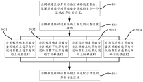
- the above step 503 can be implemented instead as steps 5031 to 5034, as shown in FIG. 7:
- Step 5031 The application determines an upper offset value Y1 between the upper boundary of the interface security area and the upper boundary of the screen of the terminal according to the boundary setting operation.
- the setting interface displays a first control for setting an upper boundary of the security area of the interface, for example, the first control is an upper boundary line that can change a position.
- the application program determines an upper offset value Y1 of the interface security area 60 according to the border setting operation, as shown in FIG. 6.
- Step 5032 The application determines a lower offset value Y2 between the lower boundary of the interface security area and the lower boundary of the screen of the terminal according to the boundary setting operation.
- a second control for setting a lower boundary of the interface security area is displayed on the setting interface.
- the second control is a lower boundary line that can change position.
- the application program determines the lower offset value Y2 of the interface security area 60 according to the border setting operation, as shown in FIG. 6.
- Step 5033 The application determines a left offset value X1 between the left border of the interface security area and the left border of the screen of the terminal according to the border setting operation.
- a third control for setting the left border of the security area of the interface is displayed on the setting interface.
- the third control is a left border line that can change position.
- the application determines the left offset value X1 of the interface security area 60 according to the border setting operation, as shown in FIG. 6.
- Step 5034 The application determines a right offset value X2 between the right border of the interface security area and the right border of the screen of the terminal according to the border setting operation.
- a fourth control for setting the right border of the security area of the interface is displayed on the setting interface, for example, the fourth control is a right border line that can change position.
- the application determines a right offset value X2 of the interface security area 60 according to the border setting operation, as shown in FIG. 6.
- step 5301, step 5302, step 5303, and step 5304 are side-by-side steps. Any two of the four steps may be performed sequentially or simultaneously. This embodiment performs the four steps. The sequence is not limited.
- the four steps of step 5301, step 5302, step 5303, and step 5304 may perform only one, two or three of them in a single setting process.
- the embodiment does not limit the number of these four steps to be performed in a single setting process, and it depends on the boundary setting operation actually triggered by the user.
- the application is an application that needs to be used in landscape mode, and the special-shaped screen gap of the terminal is formed at the upper edge in portrait mode. At this time, it is more necessary to guide the landscape mode.
- the user first sets the left and right boundaries of the interface security area, and then sets the upper and lower boundaries of the interface security area.
- FIG. 8 shows a flowchart of a display adaptation method of an application program provided by another exemplary embodiment of the present application. This embodiment is exemplified by applying the method to the terminal 100 shown in FIG. 3. The method includes:
- Step 701 The application reads the screen resolution of the terminal and determines a first aspect ratio of the terminal.
- the screen resolution is the pixel resolution on the terminal's display. Different terminals can have different screen resolutions.
- the mainstream screen resolutions are divided into:
- Step 702 According to the first aspect ratio of the terminal, the application program sets the second aspect ratio of the setting interface to the same ratio as the first aspect ratio.
- the application program sets the second aspect ratio of the setting interface according to the first aspect ratio of the terminal.
- the application sets the setting interface to 16: 9;
- the application program sets the device interface to 4: 3.
- This step optionally includes the following steps, as shown in Figure 9:
- Step 7021 the application program determines whether the first aspect ratio is close to 16: 9;
- step 7022 When the first aspect ratio is close to 4: 3, the process proceeds to step 7022; when the first aspect ratio is close to 16: 9, the process proceeds to step 7023.
- Step 7022 the application sets the height of the setting interface of the interface security area to the height of the screen resolution, and crops the width of the setting interface left and right according to the second aspect ratio 4: 3;
- the setting interface has a default resolution, which can be greater than or equal to the maximum screen resolution supported by the application.
- the setting interface is used to set at least one area boundary of the interface security area.
- the setting interface is provided by the application.
- the application sets the height of the setting interface to the height of the screen resolution, and performs at least one of left and right cropping on the width of the setting interface according to the second aspect ratio 4: 3.
- the second aspect ratio 4: 3 One.
- Step 7023 The application sets the width of the setting interface of the interface security area to the width of the screen resolution, and crops the height of the setting interface up and down according to the second aspect ratio 16: 9.
- the application sets the width of the setting interface to the width of the screen resolution, and performs at least one of the upper and lower cutting of the height of the setting interface according to the second aspect ratio 16: 9.
- the application sets the width of the setting interface to the width of the screen resolution, and performs at least one of the upper and lower cutting of the height of the setting interface according to the second aspect ratio 16: 9.
- Step 703 The application displays an interface for setting a safe area of the interface.
- the setting interface displays at least one of a left boundary line, a right boundary line, an upper boundary line, and a lower boundary line for setting an area boundary.
- the setting interface is displayed.
- the setting interface displays four types of lines: a left boundary line, a right boundary line, an upper boundary line, and a lower boundary line.
- the left boundary line and the right boundary line are displayed on the setting interface; after the left boundary and / or the right boundary of the interface security area are set, the upper boundary line and the lower boundary line are displayed.
- the upper boundary line and the lower boundary line are displayed on the setting interface; after the upper boundary and / or the lower boundary of the interface security area are set, the left boundary line and the right boundary line are displayed.
- Step 704 The application receives a boundary setting operation triggered by the user on the setting interface.
- This boundary setting operation is an operation for setting the area boundary of the interface security area.
- the boundary setting operation is an operation for setting at least one area boundary among an upper boundary, a lower boundary, a left boundary, and a right boundary of the interface security area. This boundary setting operation can be manually triggered by the user.
- the boundary setting operation can be a drag operation applied on a certain boundary line, or the boundary setting operation can be a zoom operation applied in the center of the setting interface and in a certain direction (up and down or left and right) .
- the border setting operation may be a drag gesture operation acting on the left border line, a drag gesture operation acting on the right border line, a drag gesture operation acting on the upper border line, and a drag gesture operation acting on the lower border line.
- the border setting operation may be a drag gesture operation that acts on both the left and right border lines.
- the boundary setting operation may be a drag gesture operation that acts on both the upper and lower boundary lines.
- the border setting operation may also be a first scaling operation for both the left and right border lines.
- the boundary setting operation may be a second scaling operation for both the upper and lower boundary lines.
- Step 7051 the boundary setting operation is a first drag gesture operation for zooming the left and right boundary lines, and the application program obtains a coordinate distance difference d1 of the first zoom gesture operation.
- the first zoom operation may be an opening and closing operation performed by the user's two fingers in the center of the setting interface in the horizontal direction.
- the two touch points are monitored on the touch screen of the terminal, and the distance change value of the two touch points in the horizontal direction is determined as the coordinate distance difference d1 of the first zoom gesture operation.
- Step 7061 the application sets the left offset value X1 of the left border of the interface security area to the center of the screen of the terminal according to the coordinate distance difference d1, and sets the right border of the interface security area to the center of the screen of the terminal according to the coordinate distance difference d1 Offset right offset value X2.
- the application sets the left offset value and the right offset value according to the following formula.
- Step 7052 the boundary setting operation is a first drag gesture operation for zooming the left and right boundary lines, and the application program obtains a sliding distance difference d2 of the first drag gesture operation.
- the first drag gesture operation may be a drag operation pressing on a left border line or a right border line.
- a continuously touched touch point is detected on the touch screen of the terminal, and the distance change value of the continuously touched touch point in the horizontal direction is determined as the sliding distance difference d2 of the first drag gesture operation.
- Step 7062 the application program sets the left offset value X1 of the left border of the interface security area to the center of the terminal screen according to the sliding distance difference d2, and sets the right border of the interface safe area to the center of the terminal's screen according to the sliding distance difference d2.
- the application sets the left offset value and the right offset value according to the following formula.
- Step 7053 the boundary setting operation is a second zoom gesture operation for zooming the upper and lower boundary lines, and the application program obtains the coordinate distance difference d3 of the second zoom gesture operation.
- the second zoom operation may be an opening and closing operation performed by the user's two fingers in the center of the setting interface in the vertical direction.
- the two touch points are monitored on the touch screen of the terminal, and the distance change value of the two touch points in the vertical direction is determined as the coordinate distance difference d3 of the second zoom gesture operation.
- Step 7063 the application program sets the upper offset value Y1 of the upper boundary of the interface security area to the middle of the screen of the terminal according to the coordinate distance difference d3, and sets the lower boundary of the interface security area to the middle of the screen of the terminal according to the coordinate distance difference d3 The lower offset value Y2.
- the application sets the left offset value and the right offset value according to the following formula.
- the boundary setting operation is a second drag gesture operation for dragging the upper boundary line, and the application program obtains a sliding distance difference d4 of the second drag gesture operation.
- the second drag gesture operation may be a drag operation pressed on the upper boundary line. At this time, a continuously touched touch point is detected on the touch screen of the terminal, and the distance change value of the continuously touched touch point in the horizontal direction is determined as the sliding distance difference d4 of the second drag gesture operation.
- step 7064 the application program sets an upper offset value Y1 of the upper boundary of the interface security area to the middle of the screen of the terminal according to the sliding distance difference d4.
- the application sets the upper offset value according to the following formula.
- Y1 d4 ⁇ ⁇ , where ⁇ is a preset parameter.
- Step 7055 the boundary setting operation is a third drag gesture operation for dragging the upper boundary line, and the application program obtains a sliding distance difference d5 of the third drag gesture operation.
- the third drag gesture operation may be a drag operation pressed on a lower boundary line. At this time, a continuously touched touch point is detected on the touch screen of the terminal, and the distance change value of the continuously touched touch point in the horizontal direction is determined as the sliding distance difference d5 of the third drag gesture operation.
- Step 7065 The application program sets a lower offset value Y2 of the lower boundary of the interface security area to the middle of the screen of the terminal according to the sliding distance difference d5.
- the application sets the upper offset value according to the following formula.
- Y2 d5 ⁇ ⁇ , where ⁇ is a preset parameter.
- only one of the five sets of steps 7051 and 7061, 7052 and 7062, 7052 and 7063, 7054 and 7064, and 7055 and 7065 may be performed. At least one set; in other embodiments, when there are at least two sets of steps being performed, these sets of steps may be performed simultaneously, or some of the steps may be performed first and then the remaining other steps.
- Step 707 The application program generates an interface security area adapted to the terminal according to the location parameters.
- the display adaptation method of the application is based on the user's boundary setting operation of the setting interface, and the application determines the position parameters of the area boundary of the interface security area according to the boundary setting operation, which can be performed by the user Custom adaptation of interface security areas.
- the interface security area can be set as large as possible by the user; on the other hand, the setting of the interface security area does not affect the display of the background layer of the application.
- the display area of the background layer can be larger than the area of the interface security area, thereby solving the problem.
- the related art adaption method makes the user interface of the application program display a limited field of view, and the display effect is poor.
- the user performs boundary setting operations according to the screen type of the terminal, including bangs screen, curved screen, digging screen, and other non-mainstream screens, and adjusts the area boundary of the interface security area in real time to obtain user satisfaction and adapt to the terminal.
- the interface security area can solve the problem that application manufacturers need to adapt to multiple models separately and have great development efforts.
- the left and right boundaries are bound in the settings interface so that the left offset value and the right offset value are the same offset value.
- the user flips the phone in landscape mode, such as changing the top of the phone from the left-hand direction to the right-hand direction, and the interface security area can smoothly respond to the flip without happening. Any adaptation issues ensure the display adaptability of the application's user interface.
- FIG. 10 shows a flowchart of a display adaptation method of an application provided by an exemplary embodiment of the present application. The method includes:
- Step 401 Turn on the custom adaptation function.
- the user launches a mobile game application. After the application obtains login account information, its background displays a "Custom Adaptation” control and an “Exit” control.
- Step 402 The application reads the resolution A1 ⁇ B1 of the mobile game device.
- the resolution of a mobile game device is the resolution of pixels on the display screen, measured in horizontal and vertical pixels.
- the resolution A1 ⁇ B1 means that the number of pixels in the horizontal direction is A1 and the number of pixels in the vertical direction is B1.
- Step 403 The application sets the resolution of the display interface to A1 ⁇ B1.
- the display interface refers to the same meaning of the above-mentioned "setting interface”.
- step 404 the application sets the display interface X and Y axis adaptation offsets X1, X2, Y1, and Y2 for custom adaptation to 0.
- the display interface X, Y axis adaptation offset is the area boundary of the display interface, including the left, right, upper, and lower boundaries; X1 is the straight line distance between the left boundary of the display interface and the left edge of the screen, and X2 is the display interface The straight line distance between the right border and the left border of the screen, Y1 is the straight line distance between the upper border of the display interface and the upper border of the screen, Y2 is the straight line distance between the lower border of the display interface and the lower border of the screen, X1, X2, Y1, and Y2 settings 0 (or initialized to 0), so that the area boundary of the display interface coincides with the screen boundary, as shown in FIG. 6.
- step 404 may be performed after step 406.
- step 405 the application program determines whether the resolution ratio A1 / B1 is close to 16: 9 or 4: 3.
- the resolution ratio further includes: 16:10 and 5: 4. Among them, 16:10 is common in smart TVs and laptops. This embodiment uses the resolution ratio to include 16: 9 or 4: 3 as an example for illustration, but the specific resolution ratio form is not limited.
- Step 4061 if the resolution ratio A1 / B1 is close to 16: 9, the application sets the display background width to the resolution width, and the height is cropped up and down;
- the display background is the background displayed by the display interface.
- the background can be the current background of the application or other background images.
- “height cropping” may be to crop the upper and lower borders of the display background together, or to crop one of the upper and lower borders of the display background.
- step 4062 if the resolution ratio A1 / B1 is close to 4: 3, the application sets the display background height to the resolution height, and the width is cropped to the left and right.
- the “left and right cropping” may be cropping the left and right borders of the display background together, or one of the left and right borders of the display background.
- Step 407 the application prompts to reset the application, and displays the display interface and the security zone boundary lines H1 and H2 of the display interface.
- FIG. 11 shows the boundary lines H1 and H2 in the display interface of the display adaptation method of the application.
- the boundary lines H1 and H2 may be changed in position by a drag gesture or a zoom gesture.
- FIG. 12 shows a schematic diagram of the display interface after the user performs a zoom gesture operation on the display interface and the application program sets the left and right boundaries of the display interface to the middle of the screen of the terminal in real time.
- Specific methods include:
- Step 4081 if the user has a zoom gesture
- the zoom gesture can be applied to any area of the display interface, and can be zoomed at any angle;
- the user has a zoom gesture
- the touch points of the finger and the display interface may be points on the zoom boundary lines H1, H2, or any two points on the display interface.
- Step 4091 the application reads the coordinate distance difference d1 of the zoom operation sliding
- the “coordinate distance difference d1” is calculated by the sliding distance difference of the touch point.
- the sliding distance difference between the touch points is measured at any one of the two touch points, or two are measured at the same time;
- the sliding distance difference of the touch point is measured by a change value in the horizontal direction of the touch point.
- Step 4082 if the user has a drag gesture.
- the drag gesture acts on the boundary lines H1 and H2 of the safe area of the display interface.
- the user can click or double-click the safe area boundary lines H1 and H2 of the display interface to move to the appropriate position.
- step 4092 the application reads the coordinate distance difference d2 of the drag operation.
- the drag gesture of the user is a drag operation by pressing on the boundary lines H1 and H2.
- a continuously touched touch point is monitored on the touch screen of the terminal, and a sliding distance difference d2 is determined by measuring a distance change value of the continuously touched touch point in a horizontal direction;
- the drag gesture of the user is a drag operation of clicking or double-clicking the boundary line H1 or H2, moving the boundary line H1 or H2 to an appropriate position, and clicking to place the boundary line H1 or H2.
- By measuring the level of the touch points before and after The distance change in the direction determines the sliding distance difference d2.
- the interface 1200 displayed by the application program is shown.
- the interface 1200 includes a “reset” control, a “next” control, and an “exit” control.
- step 4121 the user clicks the "Reset” control, and the application will proceed to step 407, repeating the above steps, the user can set the left and right boundaries of the display interface multiple times;
- step 4122 the user clicks the "next" control, and the application will proceed to step 413, where the user sets the upper and lower interfaces of the display interface;
- Step 4123 the user clicks "Exit” and the application will exit the custom adaptation.
- Step 4121, step 4122, and step 4123 are single-option steps, and only one of them can be performed.
- step 413 after the application sets the left and right boundaries of the display interface, the display interface is reset, and the boundary lines L1 and L2 of the safe area of the display interface are displayed.
- FIG. 13 shows the boundary lines L1 and L2 in the display interface of the display adaptation method of the application.
- FIG. 14 shows a schematic diagram of a display interface after a user gestures to zoom the upper and lower boundaries on the display interface, and the application program sets the upper and lower boundaries of the display interface to the middle of the screen of the terminal in real time.
- Specific methods include:
- Step 4141 if the user has a zoom operation gesture
- the zoom gesture can be applied to any area of the display interface, and can be zoomed at any angle;
- the user has a zoom gesture
- the touch points of the finger and the display interface may be points on the zoom boundary lines L1 and L2, or any two points on the display interface.
- Step 4151 the application reads the coordinate distance difference d3 of the zoom operation sliding
- Step 4142 if the user has a gesture of dragging the upper boundary line of the security area of the display interface, the application program receives the drag operation;
- Step 4152 the application reads the coordinate distance difference d4 of the drag operation
- Step 4173 if the user has a gesture of dragging the lower boundary line of the security area of the display interface, the application program receives the drag operation;
- Step 4153 the application reads the coordinate distance difference d4 of the drag operation
- the interface 1400 displayed by the application program includes an “Reset” control, a “Back” control, a “Confirmation” control, and an “Exit” control.
- step 4181 the user clicks the "Reset” control, and the application will proceed to step 413, and then repeat the above steps;
- step 4182 the user clicks the "back" control, and the application will proceed to step 407, and then repeat the above steps;
- Step 4183 the user clicks the "next" control, and the application proceeds to step 419;
- Step 4184 the user clicks the "Exit" control, and the application will exit the custom adaptation.
- Step 4181, step 4182, step 4183, and step 4184 are single-option steps, and only one of them can be performed.
- Step 419 Save X1, X2, Y1, and Y2.
- the application will set the offset X1, X2, Y1, and Y2 of the display interface to the screen middle of the terminal, and save it in the user information logged in to the application;
- the application program sets the display interface offsets X1, X2, Y1, and Y2 to the center of the screen of the terminal, and stores them in the terminal's memory.
- step 420 the application sets the left and right border offsets of the security areas of all interfaces to X1 and X2.
- step 421 the application sets the upper and lower boundary offsets of the security areas of all interfaces to Y1 and Y2.
- the interface of the application includes an information interface, a setting interface, a map interface, a copy interface, and so on.
- Step 422 the application completes the custom adaptation of the interface security area.
- FIG. 15 shows a schematic diagram of the screen interface of the terminal after the custom adaptation of the interface security area is completed.
- the interface 1500 includes a "reset” control, a "reset” control, and a "OK” control.
- the display adaptation method of the application is based on the user's setting of the boundary of the display interface.
- the application determines the position parameters of the area boundary of the interface security area according to the boundary setting operation, and the user can perform interface security.
- Custom adaptation of the area On the one hand, the interface security area can be set as large as possible by the user; on the other hand, the setting of the interface security area does not affect the display of the background layer of the application.
- the display area of the background layer can be larger than the area of the interface security area, thereby solving the problem.
- the related art adaption method makes the user interface of the application program display a limited field of view, and the display effect is poor.
- the user performs border setting operations according to the screen type of the terminal, including bangs screen, curved screen, and other non-mainstream screens, and adjusts the area boundary of the interface security area in real time to obtain the user's satisfaction and the interface security area suitable for the terminal It can solve the problem that application manufacturers need to adapt to multiple models separately and have great development efforts.
- FIG. 16 shows a block diagram of a display adaptation device for an application provided by an exemplary embodiment of the present application.
- the device can be implemented as all or part of a terminal through software, hardware, or a combination of both.
- the device includes:
- a display module 161 is configured to display a setting interface of an interface security area, where the setting interface is used to set at least one area boundary of the interface security area, and the interface security area is used to configure a person in the application program. The area where the machine interactive controls are displayed.
- the receiving module 162 is configured to receive a boundary setting operation triggered on the setting interface.
- the processing module 163 is configured to determine a position parameter of an area boundary of the interface security area according to the boundary setting operation.
- An adaptation module 164 is configured to generate the interface security area adapted to the terminal according to the position parameter.
- a processing module 163 is configured to determine an offset value between an area boundary of the interface security area and a screen boundary of the terminal according to the boundary setting operation received by the receiving module 162.
- the processing module 163 includes:
- a first determining unit 1631 configured to determine an upper offset value Y1 between the upper boundary of the interface security area and the upper boundary of the screen of the terminal according to the boundary setting operation received by the receiving module 162;
- a second determining unit 1632 configured to determine a lower offset value Y2 between the lower boundary of the interface security area and the lower boundary of the screen of the terminal according to the boundary setting operation received by the receiving module 162;
- a third determining unit 1633 configured to determine a left offset value X1 between the left border of the interface security area and the left border of the screen of the terminal according to the border setting operation received by the receiving module 162;
- a fourth determining unit 1634 is configured to determine a right offset value X2 between the right border of the interface security area and the right border of the screen of the terminal according to the border setting operation received by the receiving module 162.
- the processing module 163 further includes:
- a first obtaining unit 1671 configured to obtain a coordinate distance difference d1 of a first zoom gesture operation
- a second obtaining unit 1672 configured to obtain a sliding distance difference d2 of the first drag gesture operation
- a third obtaining unit 1673 configured to obtain a coordinate distance difference d3 of the second zoom gesture operation
- a fourth obtaining unit 1674 configured to obtain a sliding distance difference d4 of the second drag gesture operation
- a fifth obtaining unit 1675 configured to obtain a sliding distance difference d5 of the third drag gesture operation
- the first setting unit 1681 is configured to set a left offset value X1 of the left edge of the interface security area to the center of the screen of the terminal according to the coordinate distance difference d1 obtained by the first obtaining unit 1671, and to set a left offset value X1 according to the coordinate distance difference d1 Set the right offset value X2 of the right border of the interface security area to the middle of the screen of the terminal;
- the second setting unit 1682 is configured to set the left offset value X1 of the left border of the interface security area to the center of the screen of the terminal according to the sliding distance difference d2 obtained by the second obtaining unit 1672, and set the interface according to the sliding distance difference d2.
- a third setting unit 1683 is configured to set an upper offset value Y1 of the upper boundary of the interface security area to the middle of the screen of the terminal according to the coordinate distance difference d3 obtained by the third obtaining unit 1673, and set the interface according to the coordinate distance difference d3.
- a fourth setting unit 1684 configured to set an upper offset value Y1 of the upper boundary of the interface security area to the middle of the screen of the terminal according to the sliding distance difference d4 obtained by the fourth obtaining unit 1674;
- the fifth setting unit 1655 is configured to set a lower offset value Y2 of the lower boundary of the interface security area to the middle of the screen of the terminal according to the sliding distance difference d5 obtained by the third obtaining unit 1675.
- the reading module 165 is configured to read a screen resolution of the terminal, and determine a first aspect ratio of the terminal according to the screen resolution.
- a setting module 166 is configured to set the second aspect ratio and the first aspect ratio of the setting interface to be the same aspect ratio according to the first aspect ratio.
- the setting module 166 includes a determining unit 1661, a first setting unit 1662, and a second setting unit 1663, as shown in FIG. 19.
- the judging unit 1661 is configured to judge whether the first aspect ratio is close to one of 4: 3 and 16: 9.
- the first setting unit 1662 is configured to set the width of the setting interface of the interface security area to the width of the screen resolution when the first aspect ratio is 4: 3, and set the interface according to the second aspect ratio 4: 3.
- the height is trimmed up and down.
- a second setting unit 1663 configured to set the height of the setting interface of the interface security area to the height of the screen resolution when the second aspect ratio is 16: 9, and set the setting interface according to the second aspect ratio 16: 9 To the left or right.
- the display adaptation device of the application is based on the user's boundary setting operation on the setting interface, and the application determines the position parameters of the area boundary of the interface security area according to the boundary setting operation, which can be performed by the user.
- Custom adaptation of interface security areas On the one hand, the interface security area can be set as large as possible by the user; on the other hand, the setting of the interface security area does not affect the display of the background layer of the application.
- the display area of the background layer can be larger than the area of the interface security area, thereby solving the problem.
- the related art adaption method makes the user interface of the application program display a limited field of view, and the display effect is poor.
- FIG. 20 shows a structural block diagram of a terminal 2100 provided by an exemplary embodiment of the present application.
- the terminal 2100 can be: smartphone, tablet, MP3 player (Moving Picture Experts Group Audio Layer III, Moving Picture Experts Compression Standard Audio Level 3), MP4 (Moving Picture Expert Experts Group Audio Audio Layer IV, moving picture expert compressed standard audio Level 4) Player, laptop or desktop computer.
- the terminal 2100 may also be called other names such as user equipment, portable terminal, laptop terminal, desktop terminal, and the like.
- the terminal 2100 includes a processor 2101 and a memory 2102.
- the processor 2101 may include one or more processing cores, such as a 4-core processor, an 8-core processor, and the like.
- the processor 2101 may use at least one hardware form among Digital Signal Processing (DSP), Field-Programmable Gate Array (FPGA), and Programmable Logic Array (PLA). achieve.
- the processor 2101 may also include a main processor and a coprocessor.
- the main processor is a processor for processing data in the wake state, also called a CPU (Central Processing Unit).
- the coprocessor is Low-power processor for processing data in standby.
- the processor 2101 may be integrated with a GPU (Graphics Processing Unit, image processor), and the GPU is responsible for rendering and drawing content required to be displayed on the display screen.
- the processor 2101 may further include an AI (Artificial Intelligence) processor, and the AI processor is configured to process computing operations related to machine learning.
- AI Artificial Intelligence
- the memory 2102 may include one or more computer-readable storage media, which may be non-transitory.
- the memory 2102 may further include a high-speed random access memory, and a non-volatile memory, such as one or more disk storage devices, flash storage devices.
- the non-transitory computer-readable storage medium in the memory 2102 is used to store at least one instruction, and the at least one instruction is used to be executed by the processor 2101 to implement the application program provided by the method embodiment in this application. Display adaptation method.
- the terminal 2100 may optionally include a peripheral device interface 2103 and at least one peripheral device.
- the processor 2101, the memory 2102, and the peripheral device interface 2103 may be connected through a bus or a signal line.
- Each peripheral device can be connected to the peripheral device interface 2103 through a bus, a signal line, or a circuit board.
- the peripheral device includes at least one of a radio frequency circuit 2104, a touch display screen 2105, a camera 2106, an audio circuit 2107, a positioning component 2108, and a power source 2109.
- the peripheral device interface 2103 can be used to connect at least one peripheral device related to I / O (Input / Output) to the processor 2101 and the memory 2102.
- the processor 2101, the memory 2102, and the peripheral device interface 2103 are integrated on the same chip or circuit board; in some other embodiments, any one of the processor 2101, the memory 2102, and the peripheral device interface 2103 or Two can be implemented on separate chips or circuit boards, which is not limited in this embodiment.
- the radio frequency circuit 2104 is used for receiving and transmitting an RF (Radio Frequency) signal, also called an electromagnetic signal.
- the radio frequency circuit 2104 communicates with a communication network and other communication devices through electromagnetic signals.
- the radio frequency circuit 2104 converts electrical signals into electromagnetic signals for transmission, or converts received electromagnetic signals into electrical signals.
- the radio frequency circuit 2104 includes: an antenna system, an RF transceiver, one or more amplifiers, a tuner, an oscillator, a digital signal processor, a codec chipset, a subscriber identity module card, and the like.
- the radio frequency circuit 2104 can communicate with other terminals through at least one wireless communication protocol.
- the wireless communication protocol includes, but is not limited to: a metropolitan area network, various generations of mobile communication networks (2G, 3G, 4G, and 5G), a wireless local area network, and / or a WiFi (Wireless Fidelity) network.
- the radio frequency circuit 2104 may further include circuits related to Near Field Communication (NFC), which is not limited in this application.
- NFC Near Field Communication
- the display screen 2105 is used to display a UI (User Interface).
- the UI can include graphics, text, icons, videos, and any combination thereof.
- the display screen 2105 also has the ability to collect touch signals on or above the surface of the display screen 2105. This touch signal can be input to the processor 2101 as a control signal for processing.
- the display screen 2105 may also be used to provide a virtual button and / or a virtual keyboard, which is also called a soft button and / or a soft keyboard.
- the display screen 2105 may be one and the front panel of the terminal 2100 is provided.
- the display screen 2105 may be at least two, which are respectively provided on different surfaces of the terminal 2100 or have a folded design. In still other embodiments, the display screen 2105 may be a flexible display screen disposed on a curved surface or a folded surface of the terminal 2100. Moreover, the display screen 2105 can also be set as a non-rectangular irregular figure, that is, a special-shaped screen.
- the display 2105 can be made of materials such as LCD (Liquid Crystal Display) and OLED (Organic Light-Emitting Diode).
- the camera component 2106 is used to capture images or videos.
- the camera component 2106 includes a front camera and a rear camera.
- the front camera is disposed on the front panel of the terminal, and the rear camera is disposed on the back of the terminal.
- the camera assembly 2106 may further include a flash.
- the flash can be a monochrome temperature flash or a dual color temperature flash.
- a dual color temperature flash is a combination of a warm light flash and a cold light flash, which can be used for light compensation at different color temperatures.
- the audio circuit 2107 may include a microphone and a speaker.
- the microphone is used to collect sound waves of the user and the environment, and convert the sound waves into electrical signals and input them to the processor 2101 for processing, or input them to the radio frequency circuit 2104 to implement voice communication. For the purpose of stereo collection or noise reduction, there may be multiple microphones, which are respectively disposed at different parts of the terminal 2100.
- the microphone can also be an array microphone or an omnidirectional acquisition microphone.
- the speaker is used to convert electric signals from the processor 2101 or the radio frequency circuit 2104 into sound waves.
- the speaker can be a traditional film speaker or a piezoelectric ceramic speaker.
- the speaker When the speaker is a piezoelectric ceramic speaker, it can not only convert electrical signals into sound waves audible to humans, but also convert electrical signals into sound waves inaudible to humans for ranging purposes.
- the audio circuit 2107 may further include a headphone jack.
- the positioning component 2108 is used to locate the current geographic position of the terminal 2100 to implement navigation or LBS (Location Based Service).
- the positioning component 2108 may be a positioning component based on the United States' GPS (Global Positioning System), the Beidou system in China, the Granas system in Russia, or the Galileo system in the European Union.
- the power supply 2109 is used to power various components in the terminal 2100.
- the power source 2109 may be an alternating current, a direct current, a disposable battery, or a rechargeable battery.
- the rechargeable battery may support wired charging or wireless charging.
- the rechargeable battery can also be used to support fast charging technology.
- the terminal 2100 further includes one or more sensors 2110.
- the one or more sensors 2110 include, but are not limited to, an acceleration sensor 2111, a gyro sensor 2112, a pressure sensor 2113, a fingerprint sensor 2121, an optical sensor 2115, and a proximity sensor 2116.
- the acceleration sensor 2111 can detect the magnitude of acceleration on the three coordinate axes of the coordinate system established by the terminal 2100.
- the acceleration sensor 2111 may be used to detect components of the acceleration of gravity on three coordinate axes.
- the processor 2101 may control the touch display screen 2105 to display the user interface in a landscape view or a portrait view according to the gravity acceleration signal collected by the acceleration sensor 2111.
- the acceleration sensor 2111 may also be used for collecting motion data of a game or a user.
- the gyro sensor 2112 can detect the body direction and the rotation angle of the terminal 2100, and the gyro sensor 2112 can cooperate with the acceleration sensor 2111 to collect a 3D motion of the user on the terminal 2100. Based on the data collected by the gyro sensor 2112, the processor 2101 can implement the following functions: motion sensing (such as changing the UI according to the user's tilt operation), image stabilization during shooting, game control, and inertial navigation.
- the pressure sensor 2113 may be disposed on a side frame of the terminal 2100 and / or a lower layer of the touch display screen 2105.
- a user's holding signal to the terminal 2100 can be detected, and the processor 2101 can perform left-right hand recognition or quick operation according to the holding signal collected by the pressure sensor 2113.
- the processor 2101 controls the operable controls on the UI interface according to the user's pressure operation on the touch display screen 2105.
- the operability controls include at least one of a button control, a scroll bar control, an icon control, and a menu control.
- the fingerprint sensor 2121 is used to collect a user's fingerprint, and the processor 2101 recognizes the identity of the user based on the fingerprint collected by the fingerprint sensor 2121, or the fingerprint sensor 2121 recognizes the identity of the user based on the collected fingerprint. When the user's identity is identified as trusted, the processor 2101 authorizes the user to perform related sensitive operations, such as unlocking the screen, viewing encrypted information, downloading software, paying, and changing settings.
- the fingerprint sensor 2121 may be provided on the front, back, or side of the terminal 2100. When a physical button or a manufacturer's logo is set on the terminal 2100, the fingerprint sensor 2121 can be integrated with the physical button or the manufacturer's logo.
- the optical sensor 2115 is used to collect ambient light intensity.
- the processor 2101 may control the display brightness of the touch display screen 2105 according to the ambient light intensity collected by the optical sensor 2115. Specifically, when the ambient light intensity is high, the display brightness of the touch display screen 2105 is increased; when the ambient light intensity is low, the display brightness of the touch display screen 2105 is decreased.
- the processor 2101 may also dynamically adjust the shooting parameters of the camera component 2106 according to the ambient light intensity collected by the optical sensor 2115.
- the proximity sensor 2116 also called a distance sensor, is usually disposed on the front panel of the terminal 2100.
- the proximity sensor 2116 is used to collect the distance between the user and the front of the terminal 2100.
- the processor 2101 controls the touch display screen 2105 to switch from the bright screen state to the inactive screen state; when the proximity sensor 2116 detects When the distance between the user and the front of the terminal 2100 gradually becomes larger, the processor 2101 controls the touch display screen 2105 to switch from the rest screen state to the bright screen state.
- FIG. 20 does not constitute a limitation on the terminal 2100, and may include more or fewer components than shown in the figure, or combine certain components, or adopt different component arrangements.
- the computer-readable media may include computer storage media and communication media.
- Computer storage media includes volatile and nonvolatile, removable and non-removable media implemented in any method or technology for storage of information such as computer-readable instructions, data results, program modules or other data.
- Computer storage media include RAM, ROM, EPROM, EEPROM, flash memory, or other solid-state storage technologies, CD-ROM, DVD or other optical storage, tape cartridges, magnetic tape, disk storage, or other magnetic storage devices.
- RAM random access memory
- ROM read-only memory
- EPROM Erasable programmable read-only memory
- EEPROM electrically erasable programmable read-only memory
- flash memory or other solid-state storage technologies
- CD-ROM, DVD or other optical storage CD-ROM, DVD or other optical storage
- tape cartridges magnetic tape
- disk storage or other magnetic storage devices.
- the memory further includes one or more programs stored in the memory and configured to be executed by one or more processors.
- the one or more programs include instructions for executing the display adaptation method of the application.
- An embodiment of the present application further provides a computer-readable storage medium, where the storage medium stores at least one instruction, at least one program, code set, or instruction set, the at least one instruction, the at least one program, and the code set. Or the display adaptation method of the application program which is loaded by the processor and provided by the foregoing method embodiments.
- the present application also provides a computer program product.
- the computer program product runs on a computer, the computer is caused to execute the display adaptation method of the application program provided by the foregoing method embodiments.
Landscapes
- Engineering & Computer Science (AREA)
- Theoretical Computer Science (AREA)
- General Engineering & Computer Science (AREA)
- Physics & Mathematics (AREA)
- General Physics & Mathematics (AREA)
- Human Computer Interaction (AREA)
- Software Systems (AREA)
- Computer Hardware Design (AREA)
- User Interface Of Digital Computer (AREA)
Abstract
Description
Claims (22)
- 一种应用程序的显示适配方法,其特征在于,所述方法包括:显示界面安全区域的设置界面,所述设置界面用于对所述界面安全区域的至少一个区域边界进行设置,所述界面安全区域是用于对所述应用程序中的人机交互控件进行显示的区域;接收在所述设置界面上触发的边界设置操作;根据所述边界设置操作确定所述界面安全区域的区域边界的位置参数;根据所述位置参数生成适配于所述终端的所述界面安全区域。
- 根据权利要求1所述的方法,其特征在于,所述区域边界包括:上边界、下边界、左边界和右边界;所述根据所述边界设置操作确定所述界面安全区域的区域边界的位置参数,包括:根据所述边界设置操作确定所述界面安全区域的区域边界与所述终端的屏幕边界之间的偏移值,所述偏移值包括如下偏移值中的至少一个:所述界面安全区域的上边界与所述终端的屏幕上边界之间的上偏移值Y1;所述界面安全区域的下边界与所述终端的屏幕下边界之间的下偏移值Y2;所述界面安全区域的左边界与所述终端的屏幕左边界之间的左偏移值X1;所述界面安全区域的右边界与所述终端的屏幕右边界之间的右偏移值X2。
- 根据权利要求2所述的方法,其特征在于,所述设置界面上显示有用于设置所述左边界的左边界线和用于设置所述右边界的右边界线,所述边界设置操作包括用于缩放所述左边界线和所述右边界线的第一缩放手势操作;所述根据所述边界设置操作确定所述界面安全区域的区域边界与所述终端的屏幕边界之间的偏移值,包括:获取所述第一缩放手势操作的坐标距离差d1;根据所述坐标距离差d1设置所述界面安全区域的左边界向所述终端的屏幕中间偏移的所述左偏移值X1;根据所述坐标距离差d1设置所述界面安全区域的右边界向所述终端的屏幕中间偏移的所述右偏移值X2。
- 根据权利要求2所述的方法,其特征在于,所述设置界面上显示有用于设置所述左边界的左边界线和用于设置所述右边界的右边界线,所述边界设置操作是用于缩放所述左边界线和所述右边界线的第一拖拽手势操作;所述根据所述边界设置操作确定所述界面安全区域的区域边界与所述终端的屏幕边界之间的偏移值,包括:获取所述第一拖拽手势操作的滑动距离差d2;根据所述滑动距离差d2设置所述界面安全区域的左边界向所述终端的屏幕中间偏移的所述左偏移值X1;根据所述滑动距离差d2设置所述界面安全区域的右边界向所述终端的屏幕中间偏移的所述右偏移值X2。
- 根据权利要求2所述的方法,其特征在于,所述设置界面上显示有用于设置所述上边界的上边界线和用于设置所述下边界的下边界线,所述边界设置操作是用于缩放所述上边界线和所述下边界线的第二缩放手势操作;所述根据所述边界设置操作确定所述界面安全区域的区域边界与所述终端的屏幕边界之间的偏移值,包括:获取所述第二缩放手势操作的坐标距离差d3;根据所述坐标距离差d3设置所述界面安全区域的上边界向所述终端的屏幕中间偏移的所述上偏移值Y1;根据所述坐标距离差d3设置所述界面安全区域的下边界向所述终端的屏幕中间偏移的所述下偏移值Y2。
- 根据权利要求2所述的方法,其特征在于,所述设置界面上显示有用于设置所述上边界的上边界线,所述边界设置操作是用于拖拽所述上边界线的第二拖拽手势操作;所述根据所述边界设置操作确定所述界面安全区域的区域边界与所述终端的屏幕边界之间的偏移值,包括:获取所述第二拖拽手势操作的滑动距离差d4;根据所述滑动距离差d4设置所述界面安全区域的上边界向所述终端的屏幕 中间偏移的所述上偏移值Y1。
- 根据权利要求2所述的方法,其特征在于,所述设置界面上显示有用于设置所述下边界的下边界线,所述边界设置操作是用于拖拽所述上边界线的第三拖拽手势操作;所述根据所述边界设置操作确定所述界面安全区域的区域边界与所述终端的屏幕边界之间的偏移值,包括:获取所述第三拖拽手势操作的滑动距离差d5;根据所述滑动距离差d5设置所述界面安全区域的下边界向所述终端的屏幕中间偏移的所述下偏移值Y2。
- 根据权利要求1至7任一所述的方法,其特征在于,所述显示所述界面安全区域的设置界面,包括:读取所述终端的屏幕分辨率;根据所述屏幕分辨率确定所述终端的第一长宽比例;根据所述第一长宽比例显示所述界面安全区域的设置界面,所述设置界面的第二长宽比例与所述第一长宽比例相同。
- 根据权利要求8所述的方法,其特征在于,所述根据所述第一长宽比例显示所述界面安全区域的设置界面,包括:当所述第一长宽比例是4:3时,将所述界面安全区域的设置界面的宽度设置为所述屏幕分辨率的宽度;根据所述第二长宽比例4:3对所述设置界面的高度进行上下裁切;显示裁切后的所述第二长宽比例是4:3的设置界面。
- 根据权利要求8所述的方法,其特征在于,所述根据所述第一长宽比例显示所述界面安全区域的设置界面,包括:当所述第二长宽比例是16:9时,将所述界面安全区域的设置界面的高度设置为所述屏幕分辨率的高度;根据所述第二长宽比例16:9对所述设置界面的宽度进行左右裁切;显示裁切后的所述第二长宽比例是16:9的设置界面。
- 一种应用程序的显示适配装置,其特征在于,所述装置包括:显示模块,用于显示所述界面安全区域的设置界面,所述设置界面用于对所述界面安全区域的至少一个区域边界进行设置,所述界面安全区域是用于对所述应用程序中的人机交互控件进行显示的区域;接收模块,用于接收在所述设置界面上触发的边界设置操作;处理模块,用于根据所述边界设置操作确定所述界面安全区域的区域边界的位置参数;适配模块,用于根据所述位置参数生成适配于所述终端的所述界面安全区域。
- 根据权利要求11所述的装置,其特征在于,所述显示模块显示的所述区域边界,包括:上边界、下边界、左边界和右边界;所述处理模块,用于根据所述边界设置操作,确定所述界面安全区域的区域边界与所述终端的屏幕边界之间的偏移值;所述偏移值包括如下偏移值中的至少一个:所述界面安全区域的上边界与所述终端的屏幕上边界之间的上偏移值Y1;所述界面安全区域的下边界与所述终端的屏幕下边界之间的下偏移值Y2;所述界面安全区域的左边界与所述终端的屏幕左边界之间的左偏移值X1;所述界面安全区域的右边界与所述终端的屏幕右边界之间的右偏移值X2。
- 根据权利要求12所述的装置,其特征在于,所述显示模块显示的所述设置界面上,显示有用于设置所述左边界的左边界线和用于设置所述右边界的右边界线,所述边界设置操作是用于缩放所述左边界线和所述右边界线的第一缩放手势操作;所述处理模块,包括:第一获取单元,用于获取所述第一缩放手势操作的坐标距离差d1;第一设置单元,用于根据所述坐标距离差d1设置所述界面安全区域的左边界向所述终端的屏幕中间偏移的所述左偏移值X1,以及用于根据所述坐标距离 差d1设置所述界面安全区域的右边界向所述终端的屏幕中间偏移的所述右偏移值X2。
- 根据权利要求12所述的装置,其特征在于,所述显示模块显示的所述设置界面上,显示有用于设置所述左边界的左边界线和用于设置所述右边界的右边界线,所述边界设置操作是用于缩放所述左边界线和所述右边界线的第一拖拽手势操作;所述处理模块,包括:第二获取单元,用于获取所述第一拖拽手势操作的滑动距离差d2;第二设置单元,用于根据所述滑动距离差d2设置所述界面安全区域的左边界向所述终端的屏幕中间偏移的所述左偏移值X1,以及根据所述滑动距离差d2设置所述界面安全区域的右边界向所述终端的屏幕中间偏移的所述右偏移值X2。
- 根据权利要求12所述的装置,其特征在于,所述显示模块显示的所述设置界面上,显示有用于设置所述上边界的上边界线和用于设置所述下边界的下边界线,所述边界设置操作是用于缩放所述上边界线和所述下边界线的第二缩放手势操作;所述处理模块,包括:第三获取单元,用于获取所述第二缩放手势操作的坐标距离差d3;第三设置单元,用于根据所述坐标距离差d3设置所述界面安全区域的上边界向所述终端的屏幕中间偏移的所述上偏移值Y1,以及根据所述坐标距离差d3设置所述界面安全区域的下边界向所述终端的屏幕中间偏移的所述下偏移值Y2。
- 根据权利要求12所述的装置,其特征在于,所述显示模块显示的设置界面上,显示有用于设置所述上边界的上边界线,所述边界设置操作是用于拖拽所述上边界线的第二拖拽手势操作;所述处理模块,包括:第四获取单元,用于获取所述第二拖拽手势操作的滑动距离差d4;第四设置单元,用于根据所述滑动距离差d4设置所述界面安全区域的上边界向所述终端的屏幕中间偏移的所述上偏移值Y1。
- 根据权利要求12所述的装置,其特征在于,所述显示模块显示的所述设置界面上,显示有用于设置所述下边界的下边界线,所述边界设置操作是用于拖拽所述上边界线的第三拖拽手势操作;所述处理模块,包括:第五获取单元,用于获取所述第三拖拽手势操作的滑动距离差d5;第五设置单元,用于根据所述滑动距离差d5设置所述界面安全区域的下边界向所述终端的屏幕中间偏移的所述下偏移值Y2。
- 根据权利要求11至17任一所述的装置,其特征在于,所述装置,还包括:读取模块,用于读取所述终端的屏幕分辨率,根据所述屏幕分辨率确定所述终端的第一长宽比例;设置模块,用于根据所述第一长宽比例,将所述设置界面的第二长宽比例和所述第一长宽比例相同设置成相同的长宽比例。
- 根据权利要求18所述的装置,其特征在于,所述设置模块,包括:第一设置单元,用于当所述第一长宽比例是4:3时,将所述界面安全区域的设置界面的宽度设置为所述屏幕分辨率的宽度,并根据所述第二长宽比例4:3对所述设置界面的高度进行上下裁切;所述显示模块,用于显示裁切后的所述第二长宽比例是4:3的设置界面。
- 根据权利要求18所述的装置,其特征在于,所述设置模块,还包括:第二设置单元,用于当所述第二长宽比例是16:9时,将所述界面安全区域的设置界面的高度设置为所述屏幕分辨率的高度,并根据所述第二长宽比例16:9对所述设置界面的宽度进行左右裁切;所述显示模块,用于显示裁切后的所述第二长宽比例是16:9的设置界面。
- 一种终端,其特征在于,所述终端包括:处理器和存储器,所述存储器中存储有至少一条指令、至少一段程序、代码集或指令集,所述至少一条指令、所述至少一段程序、所述代码集或指令集由所述处理器加载并执行以实现如权利要求1至10任一所述的应用程序的显示适配方法。
- 一种计算机可读存储介质,其特征在于,所述存储介质中存储有至少一条指令、至少一段程序、代码集或指令集,所述至少一条指令、所述至少一段程序、所述代码集或指令集由所述处理器加载并执行以实现如权利要求1至10任一所述的应用程序的显示适配方法。
Priority Applications (4)
| Application Number | Priority Date | Filing Date | Title |
|---|---|---|---|
| EP19846276.4A EP3835953A4 (en) | 2018-08-09 | 2019-08-08 | DISPLAY ADAPTATION PROCEDURES AND SETUP FOR APPLICATION, DEVICE AND STORAGE MEDIUM |
| KR1020207027553A KR102491443B1 (ko) | 2018-08-09 | 2019-08-08 | 애플리케이션을 위한 디스플레이 적응 방법 및 장치, 디바이스, 및 저장 매체 |
| JP2020550807A JP7230055B2 (ja) | 2018-08-09 | 2019-08-08 | アプリケーションプログラムの表示適応方法及びその装置、端末、記憶媒体、並びにコンピュータプログラム |
| US17/016,307 US11231845B2 (en) | 2018-08-09 | 2020-09-09 | Display adaptation method and apparatus for application, and storage medium |
Applications Claiming Priority (2)
| Application Number | Priority Date | Filing Date | Title |
|---|---|---|---|
| CN201810903285.8A CN109308205B (zh) | 2018-08-09 | 2018-08-09 | 应用程序的显示适配方法、装置、设备及存储介质 |
| CN201810903285.8 | 2018-08-09 |
Related Child Applications (1)
| Application Number | Title | Priority Date | Filing Date |
|---|---|---|---|
| US17/016,307 Continuation US11231845B2 (en) | 2018-08-09 | 2020-09-09 | Display adaptation method and apparatus for application, and storage medium |
Publications (1)
| Publication Number | Publication Date |
|---|---|
| WO2020030065A1 true WO2020030065A1 (zh) | 2020-02-13 |
Family
ID=65226001
Family Applications (1)
| Application Number | Title | Priority Date | Filing Date |
|---|---|---|---|
| PCT/CN2019/099863 Ceased WO2020030065A1 (zh) | 2018-08-09 | 2019-08-08 | 应用程序的显示适配方法、装置、设备及存储介质 |
Country Status (6)
| Country | Link |
|---|---|
| US (1) | US11231845B2 (zh) |
| EP (1) | EP3835953A4 (zh) |
| JP (1) | JP7230055B2 (zh) |
| KR (1) | KR102491443B1 (zh) |
| CN (1) | CN109308205B (zh) |
| WO (1) | WO2020030065A1 (zh) |
Families Citing this family (18)
| Publication number | Priority date | Publication date | Assignee | Title |
|---|---|---|---|---|
| CN109308205B (zh) * | 2018-08-09 | 2020-12-01 | 腾讯科技(深圳)有限公司 | 应用程序的显示适配方法、装置、设备及存储介质 |
| CN110134475B (zh) * | 2019-04-17 | 2022-03-22 | 深圳壹账通智能科技有限公司 | 显示界面参数配置的方法、装置、计算机设备和存储介质 |
| CN112422734A (zh) * | 2019-08-23 | 2021-02-26 | 中移雄安信息通信科技有限公司 | 内容显示方法、装置、终端、屏幕适配网关及通信设备 |
| CN111258704A (zh) * | 2020-02-20 | 2020-06-09 | 腾讯科技(深圳)有限公司 | 应用画面的显示方法和装置、存储介质及电子装置 |
| CN111949360A (zh) * | 2020-09-01 | 2020-11-17 | 网易(杭州)网络有限公司 | 用户界面适配的方法及装置、电子设备、存储介质 |
| US12524138B2 (en) * | 2020-10-30 | 2026-01-13 | Tencent Technology (Shenzhen) Company Limited | Method and apparatus for adjusting position of virtual button, device, storage medium, and program product |
| CN112379964A (zh) * | 2020-12-02 | 2021-02-19 | 网易(杭州)网络有限公司 | 用户界面的显示控制方法、装置、计算机设备及存储介质 |
| CN115113785B (zh) * | 2021-03-17 | 2024-12-03 | 深圳市万普拉斯科技有限公司 | 应用程序操作方法、装置、计算机设备和存储介质 |
| JP7619115B2 (ja) * | 2021-03-23 | 2025-01-22 | 株式会社リコー | 表示装置、表示方法、プログラム |
| CN113190230B (zh) * | 2021-05-21 | 2024-05-03 | 广东群创信息科技有限公司 | 一种自定义设置ui界面的医疗显示方法及系统 |
| CN113391869A (zh) * | 2021-06-29 | 2021-09-14 | 南京苏宁软件技术有限公司 | 页面适配的方法、装置、计算机设备和存储介质 |
| US12236072B2 (en) * | 2021-09-13 | 2025-02-25 | Apple Inc. | Displaying on a display with an irregular feature |
| WO2023049303A1 (en) * | 2021-09-24 | 2023-03-30 | Apple Inc. | Devices, methods, and graphical user interfaces for displaying menus, windows, and cursors on a display with a notch |
| US12379822B2 (en) | 2021-09-24 | 2025-08-05 | Apple Inc. | Devices, methods, and graphical user interfaces for displaying menus, windows, and cursors on a display with a notch |
| CN114661394B (zh) * | 2022-03-01 | 2024-06-25 | 网易(杭州)网络有限公司 | 界面显示的控制方法、装置、存储介质、处理器 |
| CN115657886B (zh) * | 2022-09-23 | 2025-11-25 | 车智互联(北京)科技有限公司 | 一种页面导航栏吸附方法、移动终端及存储介质 |
| CN115658213B (zh) * | 2022-12-02 | 2023-06-09 | 荣耀终端有限公司 | 一种显示方法、电子设备及存储介质 |
| CN116617657B (zh) * | 2023-06-01 | 2026-07-21 | 网易(杭州)网络有限公司 | 游戏显示的调整方法、装置、电子设备及存储介质 |
Citations (6)
| Publication number | Priority date | Publication date | Assignee | Title |
|---|---|---|---|---|
| US20140059501A1 (en) * | 2012-08-27 | 2014-02-27 | Samsung Electronics Co., Ltd. | Screen display control method of electronic device and apparatus therefor |
| CN104298433A (zh) * | 2014-09-30 | 2015-01-21 | 小米科技有限责任公司 | 屏幕显示方法、装置及移动终端 |
| CN107632874A (zh) * | 2017-09-05 | 2018-01-26 | 广东欧珀移动通信有限公司 | 界面显示方法、装置及终端 |
| CN108073343A (zh) * | 2018-01-26 | 2018-05-25 | 维沃移动通信有限公司 | 一种显示界面调整方法及移动终端 |
| CN108182043A (zh) * | 2018-01-19 | 2018-06-19 | 维沃移动通信有限公司 | 一种信息显示方法及移动终端 |
| CN109308205A (zh) * | 2018-08-09 | 2019-02-05 | 腾讯科技(深圳)有限公司 | 应用程序的显示适配方法、装置、设备及存储介质 |
Family Cites Families (27)
| Publication number | Priority date | Publication date | Assignee | Title |
|---|---|---|---|---|
| US8456571B1 (en) * | 2004-02-20 | 2013-06-04 | Broadcast Pix, Inc. | Integrated live video production system |
| US9218792B2 (en) * | 2008-12-11 | 2015-12-22 | Nvidia Corporation | Variable scaling of image data for aspect ratio conversion |
| KR101735610B1 (ko) * | 2010-05-06 | 2017-05-15 | 엘지전자 주식회사 | 영상표시장치의 동작 방법 |
| JP5601997B2 (ja) * | 2010-12-06 | 2014-10-08 | シャープ株式会社 | 画像形成装置、及び表示制御方法 |
| KR20130052753A (ko) * | 2011-08-16 | 2013-05-23 | 삼성전자주식회사 | 터치스크린을 이용한 어플리케이션 실행 방법 및 이를 지원하는 단말기 |
| US20140298224A1 (en) | 2012-01-12 | 2014-10-02 | Mitsubishi Electric Corporation | Map display device and map display method |
| US9250768B2 (en) * | 2012-02-13 | 2016-02-02 | Samsung Electronics Co., Ltd. | Tablet having user interface |
| KR20130110715A (ko) * | 2012-03-30 | 2013-10-10 | 삼성전자주식회사 | 플렉서블 베젤 제공 방법 및 장치 |
| KR20130119129A (ko) * | 2012-04-23 | 2013-10-31 | 삼성전자주식회사 | 윈도우 크기를 조절하기 위한 방법 및 그 전자 장치 |
| JP2014016743A (ja) * | 2012-07-06 | 2014-01-30 | Sharp Corp | 情報処理装置、情報処理装置の制御方法、および情報処理装置の制御プログラム |
| JP5962465B2 (ja) * | 2012-11-28 | 2016-08-03 | ブラザー工業株式会社 | 画像処理プログラム、画像処理装置、および画像処理方法 |
| KR102118381B1 (ko) * | 2013-03-06 | 2020-06-04 | 엘지전자 주식회사 | 이동 단말기 |
| KR102137240B1 (ko) * | 2013-04-16 | 2020-07-23 | 삼성전자주식회사 | 디스플레이 영역을 조절하기 위한 방법 및 그 방법을 처리하는 전자 장치 |
| JP2015026194A (ja) * | 2013-07-25 | 2015-02-05 | シャープ株式会社 | 携帯情報端末装置 |
| US9804707B2 (en) * | 2014-09-12 | 2017-10-31 | Microsoft Technology Licensing, Llc | Inactive region for touch surface based on contextual information |
| US20160132992A1 (en) * | 2014-11-06 | 2016-05-12 | Microsoft Technology Licensing, Llc | User interface scaling for devices based on display size |
| JP6147830B2 (ja) * | 2015-10-28 | 2017-06-14 | 京セラ株式会社 | 携帯電子機器および携帯電子機器の表示方法 |
| CN105740107A (zh) * | 2016-05-04 | 2016-07-06 | 刘其锋 | 基于多层显示屏的冗余技术 |
| JP2016219026A (ja) * | 2016-07-13 | 2016-12-22 | 京セラ株式会社 | 携帯端末、無効領域設定プログラムおよび無効領域設定方法 |
| CN106354396A (zh) * | 2016-08-26 | 2017-01-25 | 乐视控股(北京)有限公司 | 界面调整方法及装置 |
| US20180059919A1 (en) * | 2016-08-26 | 2018-03-01 | Adobe Systems Incorporated | Responsive Design Controls |
| CN107291356B (zh) | 2017-08-03 | 2020-05-01 | 北京达佳互联信息技术有限公司 | 文件传输显示控制方法、装置及相应的终端 |
| CN107679120A (zh) * | 2017-09-18 | 2018-02-09 | 广东中标数据科技股份有限公司 | 一种多功能的可视化展示平台及其实现方法 |
| CN107678645A (zh) * | 2017-09-21 | 2018-02-09 | 咪咕音乐有限公司 | 一种信息显示处理方法及装置和存储介质 |
| US11119650B2 (en) * | 2017-11-09 | 2021-09-14 | Dell Products L.P. | Information handling system with a user defined touch area and user defined display area on a horizontal work surface |
| CN107943386A (zh) * | 2017-11-09 | 2018-04-20 | 珠海格力电器股份有限公司 | 一种调整显示界面尺寸的方法及设备 |
| CN108196755B (zh) * | 2018-01-30 | 2021-02-12 | 腾讯科技(深圳)有限公司 | 背景图片显示方法及装置 |
-
2018
- 2018-08-09 CN CN201810903285.8A patent/CN109308205B/zh active Active
-
2019
- 2019-08-08 JP JP2020550807A patent/JP7230055B2/ja active Active
- 2019-08-08 EP EP19846276.4A patent/EP3835953A4/en active Pending
- 2019-08-08 WO PCT/CN2019/099863 patent/WO2020030065A1/zh not_active Ceased
- 2019-08-08 KR KR1020207027553A patent/KR102491443B1/ko active Active
-
2020
- 2020-09-09 US US17/016,307 patent/US11231845B2/en active Active
Patent Citations (6)
| Publication number | Priority date | Publication date | Assignee | Title |
|---|---|---|---|---|
| US20140059501A1 (en) * | 2012-08-27 | 2014-02-27 | Samsung Electronics Co., Ltd. | Screen display control method of electronic device and apparatus therefor |
| CN104298433A (zh) * | 2014-09-30 | 2015-01-21 | 小米科技有限责任公司 | 屏幕显示方法、装置及移动终端 |
| CN107632874A (zh) * | 2017-09-05 | 2018-01-26 | 广东欧珀移动通信有限公司 | 界面显示方法、装置及终端 |
| CN108182043A (zh) * | 2018-01-19 | 2018-06-19 | 维沃移动通信有限公司 | 一种信息显示方法及移动终端 |
| CN108073343A (zh) * | 2018-01-26 | 2018-05-25 | 维沃移动通信有限公司 | 一种显示界面调整方法及移动终端 |
| CN109308205A (zh) * | 2018-08-09 | 2019-02-05 | 腾讯科技(深圳)有限公司 | 应用程序的显示适配方法、装置、设备及存储介质 |
Non-Patent Citations (1)
| Title |
|---|
| See also references of EP3835953A4 * |
Also Published As
| Publication number | Publication date |
|---|---|
| KR20200123223A (ko) | 2020-10-28 |
| EP3835953A1 (en) | 2021-06-16 |
| CN109308205B (zh) | 2020-12-01 |
| US20200409545A1 (en) | 2020-12-31 |
| US11231845B2 (en) | 2022-01-25 |
| EP3835953A4 (en) | 2021-10-13 |
| CN109308205A (zh) | 2019-02-05 |
| KR102491443B1 (ko) | 2023-01-27 |
| JP7230055B2 (ja) | 2023-02-28 |
| JP2021516818A (ja) | 2021-07-08 |
Similar Documents
| Publication | Publication Date | Title |
|---|---|---|
| CN109308205B (zh) | 应用程序的显示适配方法、装置、设备及存储介质 | |
| CN112162671B (zh) | 直播数据处理方法、装置、电子设备及存储介质 | |
| CN108710525B (zh) | 虚拟场景中的地图展示方法、装置、设备及存储介质 | |
| CN112578971B (zh) | 页面内容展示方法、装置、计算机设备及存储介质 | |
| CN111324250B (zh) | 三维形象的调整方法、装置、设备及可读存储介质 | |
| CN110427110B (zh) | 一种直播方法、装置以及直播服务器 | |
| CN111701238A (zh) | 虚拟画卷的显示方法、装置、设备及存储介质 | |
| CN108694073B (zh) | 虚拟场景的控制方法、装置、设备及存储介质 | |
| CN108376424A (zh) | 用于对三维虚拟环境进行视角切换的方法、装置、设备及存储介质 | |
| CN108737897B (zh) | 视频播放方法、装置、设备及存储介质 | |
| CN108595239A (zh) | 图片处理方法、装置、终端及计算机可读存储介质 | |
| WO2022134632A1 (zh) | 作品处理方法及装置 | |
| CN112044065B (zh) | 虚拟资源的显示方法、装置、设备及存储介质 | |
| CN112965773B (zh) | 用于信息显示的方法、装置、设备和存储介质 | |
| CN110300274A (zh) | 视频文件的录制方法、装置及存储介质 | |
| WO2022088765A1 (zh) | 交互处理方法及计算机设备 | |
| CN113157172A (zh) | 弹幕信息显示方法、发送方法、装置、终端及存储介质 | |
| CN112825040A (zh) | 用户界面的显示方法、装置、设备及存储介质 | |
| CN111064896A (zh) | 设备控制方法及电子设备 | |
| CN114153361B (zh) | 界面显示方法、装置、终端及存储介质 | |
| CN107656794B (zh) | 界面显示方法和装置 | |
| WO2024082883A1 (zh) | 虚拟对象的交互方法、装置、设备及计算机可读存储介质 | |
| WO2021218926A1 (zh) | 图像显示方法、装置和计算机设备 | |
| CN112306332A (zh) | 确定选中目标的方法、装置、设备及存储介质 | |
| CN111796990A (zh) | 资源显示方法、装置、终端及存储介质 |
Legal Events
| Date | Code | Title | Description |
|---|---|---|---|
| 121 | Ep: the epo has been informed by wipo that ep was designated in this application |
Ref document number: 19846276 Country of ref document: EP Kind code of ref document: A1 |
|
| ENP | Entry into the national phase |
Ref document number: 2020550807 Country of ref document: JP Kind code of ref document: A |
|
| ENP | Entry into the national phase |
Ref document number: 20207027553 Country of ref document: KR Kind code of ref document: A |
|
| NENP | Non-entry into the national phase |
Ref country code: DE |
|
| ENP | Entry into the national phase |
Ref document number: 2019846276 Country of ref document: EP Effective date: 20210309 |