WO2020031259A1 - ドリル - Google Patents
ドリル Download PDFInfo
- Publication number
- WO2020031259A1 WO2020031259A1 PCT/JP2018/029595 JP2018029595W WO2020031259A1 WO 2020031259 A1 WO2020031259 A1 WO 2020031259A1 JP 2018029595 W JP2018029595 W JP 2018029595W WO 2020031259 A1 WO2020031259 A1 WO 2020031259A1
- Authority
- WO
- WIPO (PCT)
- Prior art keywords
- cutting edge
- distance
- central axis
- drill
- edge
- Prior art date
- Legal status (The legal status is an assumption and is not a legal conclusion. Google has not performed a legal analysis and makes no representation as to the accuracy of the status listed.)
- Ceased
Links
Images


Classifications
-
- B—PERFORMING OPERATIONS; TRANSPORTING
- B23—MACHINE TOOLS; METAL-WORKING NOT OTHERWISE PROVIDED FOR
- B23B—TURNING; BORING
- B23B51/00—Tools for drilling machines
- B23B51/10—Bits for countersinking
- B23B51/108—Bits for countersinking having a centering drill
-
- B—PERFORMING OPERATIONS; TRANSPORTING
- B23—MACHINE TOOLS; METAL-WORKING NOT OTHERWISE PROVIDED FOR
- B23B—TURNING; BORING
- B23B51/00—Tools for drilling machines
- B23B51/02—Twist drills
-
- B—PERFORMING OPERATIONS; TRANSPORTING
- B23—MACHINE TOOLS; METAL-WORKING NOT OTHERWISE PROVIDED FOR
- B23B—TURNING; BORING
- B23B2215/00—Details of workpieces
- B23B2215/04—Aircraft components
-
- B—PERFORMING OPERATIONS; TRANSPORTING
- B23—MACHINE TOOLS; METAL-WORKING NOT OTHERWISE PROVIDED FOR
- B23B—TURNING; BORING
- B23B2226/00—Materials of tools or workpieces not comprising a metal
- B23B2226/27—Composites
- B23B2226/275—Carbon fibre reinforced carbon composites
-
- B—PERFORMING OPERATIONS; TRANSPORTING
- B23—MACHINE TOOLS; METAL-WORKING NOT OTHERWISE PROVIDED FOR
- B23B—TURNING; BORING
- B23B2251/00—Details of tools for drilling machines
- B23B2251/04—Angles, e.g. cutting angles
-
- B—PERFORMING OPERATIONS; TRANSPORTING
- B23—MACHINE TOOLS; METAL-WORKING NOT OTHERWISE PROVIDED FOR
- B23B—TURNING; BORING
- B23B2251/00—Details of tools for drilling machines
- B23B2251/12—Cross sectional views of the cutting edges
- B23B2251/127—Sharp cutting edges
-
- B—PERFORMING OPERATIONS; TRANSPORTING
- B23—MACHINE TOOLS; METAL-WORKING NOT OTHERWISE PROVIDED FOR
- B23B—TURNING; BORING
- B23B2251/00—Details of tools for drilling machines
- B23B2251/18—Configuration of the drill point
Definitions
- the present disclosure relates to a drill.
- a laminated body in which a fiber reinforced plastic (FRP) layer such as a carbon fiber reinforced plastic (CFRP) layer and a metal layer are laminated is used as a structural material of an aircraft fuselage and wings.
- a drill described in Patent Literature 1 is used to make a hole in this laminate.
- the drill disclosed in Patent Literature 1 has a cutting edge symmetrical with the center of rotation from the center of rotation to the outer periphery at the tip of the main body. This cutting edge is composed of at least three portions: a rotation center portion, an intermediate blade portion connected to the outer end thereof, and a linear outermost blade portion connected to the outer end of the intermediate blade portion. However, it decreases stepwise from the rotation center side to the outer peripheral side blade portion.
- a drill includes a body having a front end and a rear end opposite to the front end.
- the body includes a first cutting edge, a second cutting edge separated from the first cutting edge on a rear end side, an outer peripheral portion, and a flank.
- the outer peripheral portion is formed with a twist groove extending along the central axis of the body and a concave portion extending in a direction intersecting the central axis and crossing the outer peripheral portion.
- the center axis of the body extends from the front end to the rear end.
- the concave portion has a first surface continuous with the outer peripheral portion and extending from the outer peripheral portion toward the central axis, and a second surface continuous with the first surface and extending from the first surface toward the tip of the body.
- the first cutting edge is constituted by a first ridgeline formed by the flank and the surface of the twist groove.
- the second cutting edge is constituted by a second ridgeline formed by the first surface and the surface of the twist groove.
- the second outer edge of the second cutting edge is the first outer edge of the first cutting edge. It is closer to the center axis than the outer end.
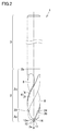
- FIG. 2 is a first side view of the drill according to the embodiment as viewed from a first direction.
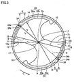
- FIG. 5 is a second side view of the drill according to the embodiment as viewed from a direction different from the first direction by 90 degrees. It is a bottom view of the drill concerning an embodiment.
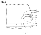
- FIG. 4 is a partially enlarged side view of a region IV shown in FIG. 1 of the drill according to the embodiment. It is the elements on larger scale of the drill concerning an embodiment.
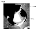
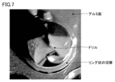
- FIG. 4 is a diagram illustrating a micrograph of an exit of a through hole when a through hole is formed in a stacked body using the drill of Example 1. It is a figure which shows the micrograph of the exit of a through-hole when a through-hole is formed in a laminated body using the drill of the comparative example.
- the drill 1 includes a body 2 having a front end 2a and a rear end 2b opposite to the front end 2a.
- the body 2 includes a first cutting edge 12, a second cutting edge 24 separated from the first cutting edge 12 on the side of the rear end 2 b, the outer peripheral portion 4, and the flank 11.
- the outer peripheral portion 4 is formed with a twist groove 8 extending along the central axis A of the body 2 and a concave portion 20 extending in a direction intersecting the central axis A and crossing the outer peripheral portion 4.
- the center axis A of the body 2 extends from the front end 2a to the rear end 2b.
- the concave portion 20 is connected to the outer peripheral portion 4 and extends from the outer peripheral portion 4 toward the central axis A.
- the first surface 20a is connected to the first surface 20a and is located from the first surface 20a toward the tip 2a of the body 2 And an extending second surface 20b.
- the first cutting edge 12 is constituted by a first ridgeline formed by the flank 11 and the surface of the twist groove 8.
- the second cutting edge 24 is constituted by a second ridgeline formed by the first surface 20a and the surface of the twist groove 8.
- a second outer side of the second cutting edges 24 is closer to the center axis A than the first outer end 12a of the first cutting edge 12.
- the second outer edge 24a of the second cutting edge 24 is more central axis than the first outer edge 12a of the first cutting edge 12 in a side view of the body 2 from the first direction.
- the length of the second cutting edge 24 is short to some extent on the A side. Therefore, the ring-shaped chips generated when the work material is drilled by the first cutting edge 12 are cut by the second cutting edge 24 and removed from the work material.
- the drill 1 according to the present disclosure can suppress generation of ring-shaped chips on a work material when performing drilling on the work material.
- the second distance r 2 is the first distance r 1 and the third distance r Greater than three .
- the first distance r 1 is the distance between the first outer edge 12a of the first cutting edge 12 and the central axis A in the plan view.
- Second distance r 2 are, in said plane view is the distance between the second outer end 24a and the central axis A of the second cutting edges 24.
- the third distance r 3 is a distance between the inner end 24b of the second cutting edge 24 and the center axis A in the plan view.
- the trajectory of the second cutting edge 24 in a plan view of the tip 2a from the second direction along the central axis A is:
- the trajectory of the first outer edge 12a of the first cutting edge 12 overlaps. Therefore, the ring-shaped chips generated when the work material is drilled by the first cutting edge 12 are more reliably cut by the second cutting edge 24 and more reliably removed from the work material.
- the drill 1 according to the present disclosure can suppress generation of ring-shaped chips on a work material when performing drilling on the work material.
- the second surface 20b is concave toward the central axis A.
- Distance L 3 between the inner end 24b of the second cutting edge 24 bottom 20c of the second surface 20b is 10% or less than 1% of the drill diameter D.
- the bottom 20c of the second surface 20b is a portion of the second surface 20b where the distance from the central axis A is minimum.
- Drill diameter D is twice the second distance r 2. Because the distance L 3 between the bottom 20c of the inner end 24b and the second surface 20b of the second cutting edge 24 is 1% or more of the drill diameter D, the chips of the rings that are cut by the second cutting edges 24 It is discharged by the recess 20.
- the ring-shaped chips cut by the second cutting edge 24 can be prevented from adhering to the second cutting edge 24.
- the length L 2 of the second cutting edge 24 is 0.15 mm or more and 0.35 mm or less. Since the length L 2 of the second cutting edge 24 is 0.15 mm or more, the ring-shaped chips generated when the workpiece is drilled by the first cutting edge 12 are more likely to be cut by the second cutting edge 24. It is reliably cut and more reliably removed from the work material. Since the length L 2 of the second cutting edge 24 is equal to or less than 0.35 mm, in addition to the ring-shaped chips already generated by the first cutting edge 12, the work material newly cut by the second cutting edge 24 is removed. Chips can be prevented from adhering to the second cutting edge 24 and generating ring-shaped chips on the work material.
- the tip angle (second tip angle ⁇ ) of the second cutting edge 24 is 170 degrees or more and 190 degrees or less. Since the tip angle (second tip angle ⁇ ) of the second cutting edge 24 is 170 degrees or more, generation of ring-shaped chips due to plastic deformation of the work material can be suppressed. Since the tip angle (second tip angle ⁇ ) of the second cutting edge 24 is equal to or less than 190 degrees, a decrease in mechanical strength of the second cutting edge 24 is suppressed, and the second cutting edge 24 is used during processing of a work material. Can be prevented from being damaged.
- the distance L 1 between the first outer end 12a and the second outer end 24a in the direction in which the central axis A extends is 1.0 mm or more. 3.0 mm or less. Since the distance L 1 is equal to or less than 3.0 mm, ring-shaped chips generated when the work material is drilled by the first cutting edge 12 can be prevented from adhering to the second cutting edge 24. Since this distance L 1 is 1.0mm or more, and it is possible to form the second surface 20b which is recessed toward the central axis A, thereby facilitating removal of the ring-shaped chips. Further, the second cutting edge 24 can be easily formed near the first cutting edge 12 without excessively reducing the mechanical strength of the tip 2a of the body 2.
- the twist angle ⁇ of the twist groove 8 is not less than 20 degrees and not more than 40 degrees.
- the first cutting edge 12 is a single angle type.
- the drill 1 is used, for example, for making a hole in a work material.
- the work material is, for example, a laminate in which a fiber reinforced plastic (FRP) layer such as a carbon fiber reinforced plastic (CFRP) layer or a glass fiber reinforced plastic (GFRP) layer and a metal layer are laminated.
- FRP fiber reinforced plastic
- CFRP carbon fiber reinforced plastic
- GFRP glass fiber reinforced plastic
- the drill 1 includes a body 2 and a shank 3.
- the body 2 has a front end 2a and a rear end 2b opposite to the front end 2a.
- the body 2 is made of, for example, a cemented carbide.
- a diamond coating may be applied to the surface of the body 2.
- the shank 3 is provided at the rear end 2b of the body 2.
- the shank 3 is a handle held by the machine tool during use.
- the body 2 has a central axis A.
- the center axis A is an axis serving as a rotation center of the drill 1.
- the center axis A of the body 2 extends from the front end 2a to the rear end 2b.
- the body 2 includes an outer peripheral portion 4.
- the outer peripheral portion 4 includes an outer peripheral surface 5 which is an outer peripheral side surface of the body 2.
- the outer peripheral portion 4 may further include a margin 6.
- the margin 6 is provided at the leading edge of the outer peripheral portion 4 (the front edge of the outer peripheral portion 4 in the rotation direction C of the drill 1 (see FIG. 3)) and protrudes from the outer peripheral surface 5.
- the margin 6 forms a gap between the work material and the outer peripheral surface 5 of the first portion 2p during processing of the work material, and prevents the outer peripheral surface 5 from contacting the work material.
- the outer peripheral portion 4 is formed with a twist groove 8 extending along the central axis A of the body 2.
- the twist groove 8 is formed from the front end 2a to the vicinity of the rear end 2b.
- the twist groove 8 is spirally formed around the central axis A. Chips cut out from the work material during processing of the work material are discharged from the twist groove 8.
- a plurality of twist grooves 8 may be formed.
- the twist angle ⁇ of the twist groove 8 may be, for example, 10 degrees or more, or 20 degrees or more.
- the twist angle ⁇ of the twist groove 8 may be, for example, 40 degrees or less, or 30 degrees or less. As shown in FIG. 1, the twist angle ⁇ of the twist groove 8 is an angle between the central axis A and the extending direction of the twist groove 8.
- the body 2 includes a first portion 2p, a second portion 2q, and a recess 20 between the first portion 2p and the second portion 2q.
- the first portion 2p includes the tip 2a of the body 2.
- the second portion 2q includes a rear end 2b of the body 2.
- the diameter of the second portion 2q gradually increases from the concave portion 20 of the second portion 2q toward the rear end 2b of the second portion 2q.
- the concave portion 20 is concave from the outer peripheral portion 4 toward the central axis A.
- the recess 20 is formed, for example, by polishing the outer peripheral portion 4 with a grindstone.
- the first portion 2 p includes the first cutting edge 12, the flank 11, the rake face 10, and the outer peripheral portion 4.
- the twist groove 8 also extends to the first portion 2p.
- the first cutting edge 12 is constituted by a first ridgeline formed by the flank 11 and the surface of the twist groove 8. A part of the surface of the twist groove 8 forms a rake face 10.
- the first cutting edge 12 includes a first outer end 12a that is a distal end of the first cutting edge 12 from the central axis A.
- the first cutting edge 12 is of a single angle type.
- the first cutting edge 12 may be a double-angle type including a first cutting edge portion and a second cutting edge portion having different tip angles, or a first cutting edge portion and a second cutting edge portion having different tip angles. It may be a triple angle type including two cutting edge portions and a third cutting edge portion.
- the first portion 2p may further include a rear surface 14, a tip ridge line 15, and a thinning portion 17.
- the rear surface 14 is continuous with the flank 11 and is in a direction opposite to the rotation direction C of the drill 1 with respect to the flank 11.
- the tip ridgeline 15 is a ridgeline formed by the flank 11 and the rear face 14.
- the first tip angle of the first portion 2p may be 90 degrees or more, or 110 degrees or more.
- the first tip angle of the first portion 2p may be 160 degrees or less, or 140 degrees or less.
- the first tip angle of the first portion 2p is equal to the tip ridge line 15 in a side view of the drill 1 from a direction perpendicular to the extension direction of the tip ridge line 15 and the extension direction of the central axis A. Defined as the angle between.
- the thinning portion 17 reduces the cutting resistance of the drill 1 during processing of a work material.
- the concave portion 20 extends in a direction intersecting with the central axis A.
- the concave portion 20 crosses the outer peripheral portion 4.
- the body 2 is constricted, and the concave portion 20 is a constricted portion of the body 2.
- the angle between the central axis A and the extending direction of the recess 20 is, for example, 80 ° or more and 100 ° or less.
- the recess 20 is shallower than the twist groove 8.
- the concave portion 20 is connected to the outer peripheral portion 4 and extends from the outer peripheral portion 4 toward the central axis A; and the first surface 20a is connected to the first surface 20a and is located on the tip 2a side of the body 2 from the first surface 20a. And a second surface 20b extending in the direction.
- the first surface 20a may be a flat surface.
- the second surface 20b may be a concave surface that is concave from the first surface 20a toward the central axis A.
- the body 2 includes a second cutting edge 24 which is spaced from the first cutting edge 12 on the side of the rear end 2 b.
- the second cutting edge 24 is formed by the surface of the twist groove 8 and the first surface 20 a of the recess 20, and is constituted by a second ridge line adjacent to the leading edge of the outer peripheral portion 4.
- the second cutting edge 24 includes a second outer end 24a that is a distal end of the second cutting edge 24 from the central axis A, and an inner end 24b that is a proximal end of the second cutting edge 24 from the central axis A. including.
- the second surface 20b is continuous with the inner end 24b of the second cutting edge 24.
- the second surface 20b is recessed from the inner end 24b of the second cutting edge 24 toward the central axis A.
- FIGS. 1 and 4 a side view of the body 2 from the first direction in which the distance L 4 between the central axis A of the body 2 and the first outer edge 12a of the first cutting edge 12 is largest.
- the second outer edge 24 a of the second cutting edge 24 is closer to the center axis A than the first outer edge 12 a of the first cutting edge 12.
- the first cutting blade 12 first outer end 12a Is smaller than the distance L 4 between the center axis A and the center axis A.
- the length L 2 of the second cutting edge 24 may also be 0.35mm or less, may be 0.25mm or less.
- the length L 2 of the second cutting edge 24 is defined as the length between the second outer end 24a and an inner end 24b of the second cutting edges 24. Since the length L 2 of the second cutting edge 24 is 0.35mm or less, already ring-shaped chips in addition to the newly cut have been of the workpiece by the second cutting edge 24 of the generated by the first cutting edges 12 Chips can be prevented from adhering to the second cutting edge 24 and generating ring-shaped chips.
- the length L 2 of the second cutting edge 24 may be 0.15mm or more. Since the length L 2 of the second cutting edge 24 is 0.15 mm or more, ring-shaped chips generated when the work material is drilled by the first cutting edge 12 are removed by the second cutting edge 24. It is more reliably cut and more reliably removed from the work material.
- the second distance r 2 is greater than the first distance r 1 and the third distance r 3.
- the first distance r 1 is a distance between the first outer edge 12a of the first cutting edge 12 and the center axis A in a plan view of the tip 2a from the second direction along the center axis A.
- the second distance r 2 is the distance between the second outer edge 24a of the second cutting edge 24 and the central axis A in plan view of the tip 2a from the second direction along the central axis A.
- the third distance r 3 is a distance between the inner end 24b of the second cutting edge 24 and the central axis A in a plan view of the tip 2a from the second direction along the central axis A.
- a plan view of the tip 2 a from the second direction along the central axis A is viewed.
- the trajectory of the second cutting edge 24 is the trajectory of the first outer edge 12a of the first cutting edge 12 (the trajectory of the first outer edge 12a of the first cutting edge 12 is a line 12p extending parallel to the central axis A). ) And overlap.
- a ring-shaped chip generated when the work material is drilled by the first cutting edge 12 (for example, a ring-shaped ring generated in the metal layer in a laminate in which the CFRP layer and the metal layer are stacked) Chip) is reliably cut by the second cutting edge 24 and is reliably removed from the work material.
- the second tip angle ⁇ of the second cutting edge 24 is not less than 170 degrees and not more than 190 degrees. Since the second tip angle ⁇ of the second cutting edge 24 is 170 degrees or more, a ring-shaped chip due to plastic deformation of the work material (for example, in a laminate in which a CFRP layer and a metal layer are stacked, The generation of ring-shaped chips generated in the metal layer due to plastic deformation can be suppressed. Since the second tip angle ⁇ of the second cutting edge 24 is 190 degrees or less, a decrease in mechanical strength of the second cutting edge 24 is suppressed, and the second cutting edge 24 is damaged during processing of a work material. Can be prevented.
- the distance L 3 between the bottom 20c of the inner end 24b of the second cutting edge 24 and the second surface 20b is 10% or less than 1% of the drill diameter D.
- the bottom 20c of the second surface 20b is a portion of the surface of the second surface 20b where the distance from the central axis A is minimum.
- Distance L 3 between the inner end 24b of the second cutting edge 24 bottom 20c of the second surface 20b shows the depth of the depression in the second surface 20b.
- the distance L 3 between the inner end 24b of the second cutting edge 24 and the bottom portion 20c of the second surface 20b has an inner end 24b of the second cutting edge 24 in plan view from the third direction first It means the distance between the two surfaces 20b and the bottom 20c.
- the third direction is the second cutting edge when viewed from the side of the drill 1 (body 2) from the direction in which the distance between the inner end 24b of the second cutting edge 24 and the bottom 20c of the second surface 20b appears to be the largest.
- the drill diameter D is twice the second distance r 2.
- the drill diameter D is a distance between the second outer edge 24a of one second cutting edge 24 and the second outer edge 24a of the other second cutting edge 24.
- the distance L 3 between the bottom 20c of the inner end 24b and the second surface 20b of the second cutting edge 24 is 1% or more of the drill diameter D, the chips of the rings that are cut by the second cutting edges 24 It is discharged by the recess 20.
- the ring-shaped chips cut by the second cutting edge 24 can be prevented from adhering to the second cutting edge 24. Since the distance L 3 between the inner end 24b of the second cutting edge 24 bottom 20c of the second surface 20b is not more than 10% of the drill diameter D, it is prevented excessive reduction in the mechanical strength of the drill 1 In addition, the drill 1 is not easily broken.
- the bottom 20c of the second surface 20b is located at the center of three regions obtained by equally dividing the ridge. It is located in the area or the area on the inner end 24b side of the second cutting edge 24.
- the distance L 1 between the first outer end 12a and a second outer end 24a in the direction in which the center axis A extends is less than 1.0mm 3.0mm or less. Since the distance L 1 is equal to or less than 3.0 mm, ring-shaped chips generated when the work material is drilled by the first cutting edge 12 can be prevented from adhering to the second cutting edge 24. Since this distance L 1 is 1.0mm or more, and it is possible to form the second surface 20b which is recessed toward the central axis A, thereby facilitating removal of the ring-shaped chips. Further, the second cutting edge 24 can be easily formed near the first cutting edge 12 without excessively reducing the mechanical strength of the first portion 2p of the body 2.
- Example 1-5 (Sample preparation) The drill of Example 1-5 and the drill of the comparative example were prepared. In the drill of Example 1-5 and the drill of the comparative example, the length L 2 of the second cutting edge 24, the second tip angle ⁇ of the second cutting edge 24, and the first outer end 12a and the second outer end 24a are different. The distance L 1 between them and the twist angle ⁇ of the twist groove 8 are as shown in Table 1.
- the body 2 is made of a cemented carbide, and the surface of the body 2 is coated with diamond.
- the first tip angle was 130 °
- the drill diameter D was 4.8 mm.
- the work material is a laminate in which a CFRP plate having a thickness of 5.0 mm and an aluminum plate having a thickness of 5.0 mm are laminated.
- the drill of Example 1-5 and the drill of the comparative example were moved from the CFRP plate side to the aluminum plate with respect to the laminate to make a hole in the laminate, and ring-shaped chips were generated in the metal layer. It was observed whether or not to do so.
Landscapes
- Engineering & Computer Science (AREA)
- Mechanical Engineering (AREA)
- Drilling Tools (AREA)
Abstract
Description
FRP層側から金属層側に向けて特許文献1のドリルを積層体に対して移動させて積層体に孔開け加工を施すと、金属層にリング状の切屑が発生することがあった。本発明の一態様は、上記のような課題を解決するためになされたものであり、その目的は、被削材に孔開け加工を施す際に、被削材にリング状の切屑が発生することを抑制し得るドリルを提供することである。
本発明の一態様によれば、被削材に孔開け加工を施す際に、被削材にリング状の切屑が発生することが抑制され得る。
まず、本発明の実施形態の概要について説明する。
(4)上記(1)~(3)に係るドリル1において、第2切れ刃24の長さL2は、0.15mm以上0.35mm以下である。第2切れ刃24の長さL2が0.15mm以上であるため、被削材を第1切れ刃12によって孔開け加工する際に発生したリング状の切屑が、第2切れ刃24によってより確実に切断されて、被削材からより確実に除去される。第2切れ刃24の長さL2が0.35mm以下であるため、第1切れ刃12によって既に発生したリング状の切屑に加えて第2切れ刃24で新たに切削された被削材の切屑が第2切れ刃24に付着して、被削材にリング状の切屑が発生することが防止され得る。
以下、図面に基づいて本開示の実施形態を説明する。なお、以下の図面において同一または相当する部分には同一の参照番号を付し、その説明は繰返さない。
外周部4には、ボディ2の中心軸Aに沿って延在するねじれ溝8が形成されている。ねじれ溝8は、先端2aから後端2bの近くにかけて形成されている。ねじれ溝8は、中心軸A回りに螺旋状に形成されている。被削材の加工時に被削材から切り出される切屑は、ねじれ溝8から排出される。ねじれ溝8は、複数形成されてもよい。ねじれ溝8のねじれ角αは、例えば、10度以上であってもよく、20度以上であってもよい。ねじれ溝8のねじれ角αは、例えば、40度以下であってもよく、30度以下であってもよい。図1に示されるように、ねじれ溝8のねじれ角αは、中心軸Aとねじれ溝8の延在方向との間の角度である。
図1及び図4に示されるように、ボディ2の中心軸Aと第1切れ刃12の第1外側端12aとの間の距離L4が最も大きく見える第1方向からのボディ2の側面視において、第2切れ刃24の第2外側端24aが第1切れ刃12の第1外側端12aよりも中心軸A側にある。言い換えると、第1方向からのボディ2の側面視において、第2切れ刃24の第2外側端24aと中心軸Aとの間の距離L5は、第1切れ刃12の第1外側端12aと中心軸Aとの間の距離L4よりも小さい。
第2切れ刃24の長さL2は、0.35mm以下であってもよく、0.25mm以下であってもよい。第2切れ刃24の長さL2は、第2切れ刃24の第2外側端24aと内側端24bとの間の長さとして定義される。第2切れ刃24の長さL2が0.35mm以下であるため、第1切れ刃12によって既に発生したリング状の切屑に加えて第2切れ刃24で新たに切削された被削材の切屑が第2切れ刃24に付着して、リング状の切屑が発生することが防止され得る。第2切れ刃24の長さL2は、0.15mm以上であってもよい。第2切れ刃24の長さL2は、0.15mm以上であるため、被削材を第1切れ刃12によって孔開け加工する際に発生したリング状の切屑が、第2切れ刃24によってより確実に切断されて、被削材からより確実に除去される。
本明細書において、第2切れ刃24の内側端24bと第2面20bの底部20cとの間の距離L3は、第3方向からの平面視における第2切れ刃24の内側端24bと第2面20bの底部20cとの間の距離を意味する。第3方向は、第2切れ刃24の内側端24bと第2面20bの底部20cとの間の距離が最も大きく見える方向からのドリル1(ボディ2)の側面視したときに、第2切れ刃24の内側端24bから中心軸Aに向かう方向における第2切れ刃24の内側端24bと第2面20bの底部20cとの間の距離が最も大きく見える方向である。図3に示されるように、ドリル径Dは、第2の距離r2の2倍である。本明細書において、ドリル径Dは、一方の第2切れ刃24の第2外側端24aと他方の第2切れ刃24の第2外側端24aとの間の距離である。
(サンプル準備)
実施例1-5のドリルと比較例のドリルとを準備した。実施例1-5のドリル及び比較例のドリルにおける、第2切れ刃24の長さL2、第2切れ刃24の第2先端角θ、第1外側端12aと第2外側端24aとの間の距離L1、ねじれ溝8のねじれ角αは、表1に示されるとおりである。実施例1-5のドリルでは、ボディ2の中心軸Aと第1切れ刃12の第1外側端12aとの間の距離L4が最も大きく見える第1方向からのボディ2の側面視において、第2切れ刃24の第2外側端24aは第1切れ刃12の第1外側端12aよりも中心軸A側にある。これに対し、比較例のドリルでは、当該第1方向からのボディ2の側面視において、第2切れ刃24の第2外側端24aは第1切れ刃12の第1外側端12aよりも中心軸Aとは反対側にある。実施例1-5のドリル及び比較例のドリルでは、ボディ2は、超硬合金で作られており、ボディ2の表面にダイヤモンドコーティングが施されている。なお、実施例1-5のドリル及び比較例のドリルでは、第1先端角は130°であり、ドリル径Dは4.8mmである。

実施例1-5のドリル及び比較例のドリルを用いて、被削材に対して孔開け加工を施した。被削材は、5.0mmの厚さを有するCFRP板と5.0mmの厚さを有するアルミ板とが積層された積層体である。実施例1-5のドリル及び比較例のドリルを、CFRP板側からアルミ板に向けて、積層体に対して移動させて積層体に孔開け加工を施し、金属層にリング状の切屑が発生するか否かを観察した。
図6に示されるように、実施例1のドリルを用いて積層体に孔開け加工を施すと、金属層にリング状の切屑が発生しなかった。同様に、実施例2-5のドリルを用いて積層体に孔開け加工を施すと、金属層にリング状の切屑が発生しなかった。これに対し、図7に示されるように、比較例のドリルを用いて積層体に孔開け加工を施すと、金属層にリング状の切屑が発生した。
Claims (8)
- 先端と、前記先端の反対側の端である後端とを有するボディを備え、
前記ボディは、第1切れ刃と、前記第1切れ刃に対して前記後端の側に離間されている第2切れ刃と、外周部と、逃げ面とを含み、
前記外周部には、前記ボディの中心軸に沿って延在するねじれ溝と、前記中心軸と交差する方向に延在しかつ前記外周部を横切る凹み部とが形成されており、前記ボディの前記中心軸は、前記先端から前記後端まで延在しており、
前記凹み部は、前記外周部に連なりかつ前記外周部から前記中心軸に向けて延在する第1面と、前記第1面に連なりかつ前記第1面から前記ボディの前記先端の側に延在する第2面とを含み、
前記第1切れ刃は、前記逃げ面と前記ねじれ溝の表面とによって形成される第1稜線によって構成されており、
前記第2切れ刃は、前記第1面と前記ねじれ溝の前記表面とによって形成される第2稜線によって構成されており、
前記ボディの前記中心軸と前記第1切れ刃の第1外側端との間の距離が最も大きく見える第1方向からの前記ボディの側面視において、前記第2切れ刃の第2外側端は前記第1切れ刃の前記第1外側端よりも前記中心軸側にある、ドリル。 - 前記中心軸に沿う第2方向からの前記先端の平面視において、第2の距離は、第1の距離及び第3の距離よりも大きく、
前記第1の距離は、前記平面視における、前記第1切れ刃の前記第1外側端と前記中心軸との間の距離であり、
前記第2の距離は、前記平面視における、前記第2切れ刃の前記第2外側端と前記中心軸との間の距離であり、
前記第3の距離は、前記平面視における、前記第2切れ刃の内側端と前記中心軸との間の距離である、請求項1に記載のドリル。 - 前記第2面は、前記中心軸に向かって凹んでおり、
前記第2切れ刃の前記内側端と前記第2面の底部との間の距離は、ドリル径の1%以上10%以下であり、
前記第2面の前記底部は、前記第2面のうち前記中心軸との距離が最小となる部分であり、
前記ドリル径は、前記第2の距離の2倍である、請求項2に記載のドリル。 - 前記第2切れ刃の長さは、0.15mm以上0.35mm以下である、請求項1から請求項3のいずれか1項に記載のドリル。
- 前記第2切れ刃の先端角は、170度以上190度以下である、請求項1から請求項4のいずれか1項に記載のドリル。
- 前記中心軸が延在する方向における前記第1外側端と前記第2外側端との間の距離は、1.0mm以上3.0mm以下である、請求項1から請求項5のいずれか1項に記載のドリル。
- 前記ねじれ溝のねじれ角は20度以上40度以下である、請求項1から請求項6のいずれか1項に記載のドリル。
- 前記第1切れ刃は、シングルアングル型である、請求項1から請求項7のいずれか1項に記載のドリル。
Priority Applications (6)
| Application Number | Priority Date | Filing Date | Title |
|---|---|---|---|
| PCT/JP2018/029595 WO2020031259A1 (ja) | 2018-08-07 | 2018-08-07 | ドリル |
| JP2019520465A JP6729853B2 (ja) | 2018-08-07 | 2018-08-07 | ドリル |
| US16/473,397 US11229959B2 (en) | 2018-08-07 | 2018-08-07 | Drill |
| KR1020197017757A KR102150220B1 (ko) | 2018-08-07 | 2018-08-07 | 드릴 |
| CN201880005542.4A CN111010869B (zh) | 2018-08-07 | 2018-08-07 | 钻头 |
| EP18880079.1A EP3636370A4 (en) | 2018-08-07 | 2018-08-07 | DRILL |
Applications Claiming Priority (1)
| Application Number | Priority Date | Filing Date | Title |
|---|---|---|---|
| PCT/JP2018/029595 WO2020031259A1 (ja) | 2018-08-07 | 2018-08-07 | ドリル |
Publications (1)
| Publication Number | Publication Date |
|---|---|
| WO2020031259A1 true WO2020031259A1 (ja) | 2020-02-13 |
Family
ID=69415199
Family Applications (1)
| Application Number | Title | Priority Date | Filing Date |
|---|---|---|---|
| PCT/JP2018/029595 Ceased WO2020031259A1 (ja) | 2018-08-07 | 2018-08-07 | ドリル |
Country Status (6)
| Country | Link |
|---|---|
| US (1) | US11229959B2 (ja) |
| EP (1) | EP3636370A4 (ja) |
| JP (1) | JP6729853B2 (ja) |
| KR (1) | KR102150220B1 (ja) |
| CN (1) | CN111010869B (ja) |
| WO (1) | WO2020031259A1 (ja) |
Cited By (3)
| Publication number | Priority date | Publication date | Assignee | Title |
|---|---|---|---|---|
| US11554424B1 (en) | 2016-02-14 | 2023-01-17 | Hongjia Wang | Twist drill |
| US20230405691A1 (en) * | 2020-11-10 | 2023-12-21 | MAPAL Fabrik für Präzisionswerkzeuge Dr. Kress KG | Tool |
| US12479036B2 (en) | 2019-12-20 | 2025-11-25 | Guehring Kg | Twist drill bit having a cutting tip with a stepped structure |
Families Citing this family (1)
| Publication number | Priority date | Publication date | Assignee | Title |
|---|---|---|---|---|
| USD1092579S1 (en) * | 2023-02-01 | 2025-09-09 | Sumitomo Electric Hardmetal Corp. | Cutting tool |
Citations (6)
| Publication number | Priority date | Publication date | Assignee | Title |
|---|---|---|---|---|
| JPS5511897U (ja) * | 1978-07-11 | 1980-01-25 | ||
| JP2009172708A (ja) | 2008-01-23 | 2009-08-06 | Sumitomo Electric Ind Ltd | 繊維強化複合材の穴あけ工具と穴あけ方法 |
| JP2010240835A (ja) * | 2009-04-07 | 2010-10-28 | Sandvik Intellectual Property Ab | ソリッドステップドリル |
| WO2013099841A1 (ja) * | 2011-12-27 | 2013-07-04 | 住友電気工業株式会社 | ドリル |
| JP2015511543A (ja) * | 2012-03-26 | 2015-04-20 | マパル ファブリック フュール プラツィジョンズベルクゼウグ ドクトル.クレス カーゲー | ドリル |
| CN104772505A (zh) * | 2015-03-27 | 2015-07-15 | 镇江锐诚精密工具有限公司 | 一种防堵钻头结构 |
Family Cites Families (34)
| Publication number | Priority date | Publication date | Assignee | Title |
|---|---|---|---|---|
| US1384733A (en) * | 1921-07-12 | Twlst-dkill | ||
| US750537A (en) * | 1904-01-26 | Drilling-tool | ||
| US867639A (en) * | 1906-05-21 | 1907-10-08 | George J Bragg | Twist-drill. |
| US1000067A (en) | 1911-03-16 | 1911-08-08 | Paul C Seegmueller | Drill. |
| US2322894A (en) * | 1939-06-29 | 1943-06-29 | Rustless Iron & Steel Corp | Twist drill |
| US2332295A (en) * | 1941-11-07 | 1943-10-19 | Western Electric Co | Drill |
| US2646701A (en) * | 1949-12-27 | 1953-07-28 | Peter A Letien | Stepped edge cutting tool |
| US3667857A (en) * | 1970-10-30 | 1972-06-06 | Nat Twist Drill & Tool Co | Combined drill and reamer construction |
| US3786713A (en) * | 1971-10-15 | 1974-01-22 | Illinois Tool Works | Chip breaker drill screw |
| US3913196A (en) * | 1974-08-29 | 1975-10-21 | Lear Siegler Inc | Rotary cutting tool |
| JPS6045607U (ja) * | 1983-09-03 | 1985-03-30 | 株式会社 協和工機 | 段付ドリル |
| DE3730378A1 (de) * | 1987-09-10 | 1989-03-23 | Micro Crystal Ag | Schneidwerkzeug, insbesondere bohrer und/oder fraeser |
| JPH0621604Y2 (ja) * | 1987-09-18 | 1994-06-08 | 三菱マテリアル株式会社 | 段付きドリル |
| JP2678016B2 (ja) * | 1988-06-07 | 1997-11-17 | 菱高精機株式会社 | 先端刃付リーマ |
| DE8912860U1 (de) * | 1989-10-31 | 1990-02-01 | Hertel AG Werkzeuge + Hartstoffe, 8510 Fürth | Spiralbohrer |
| DE4231381A1 (de) * | 1992-09-19 | 1994-03-24 | Mitsubishi Materials Corp | Bohrer |
| JP3662684B2 (ja) * | 1996-09-05 | 2005-06-22 | カヤバ工業株式会社 | 切削工具 |
| US6126367A (en) * | 1998-03-31 | 2000-10-03 | Reed; Gary Jack | Precision drill bit |
| US7575401B1 (en) * | 2004-11-18 | 2009-08-18 | Precorp, Inc. | PCD drill for composite materials |
| DE102005014422B4 (de) * | 2005-03-24 | 2019-10-24 | EMUGE-Werk Richard Glimpel GmbH & Co. KG Fabrik für Präzisionswerkzeuge | Bohrgewindefräser |
| JP2008000836A (ja) | 2006-06-21 | 2008-01-10 | Sumitomo Electric Hardmetal Corp | ドリル |
| US7665935B1 (en) * | 2006-07-27 | 2010-02-23 | Precorp, Inc. | Carbide drill bit for composite materials |
| US8714890B2 (en) * | 2007-02-09 | 2014-05-06 | The Boeing Company | Cutter for drilling and reaming |
| SE531188C2 (sv) * | 2007-05-29 | 2009-01-13 | Sandvik Intellectual Property | Borrkropp för spånavskiljande bearbetning |
| JP5675524B2 (ja) * | 2011-07-26 | 2015-02-25 | 本田技研工業株式会社 | 切削加工用工具 |
| KR20130032671A (ko) * | 2011-09-23 | 2013-04-02 | 대구텍 유한회사 | 복합 소재용 드릴 공구 |
| JP2014037008A (ja) * | 2012-08-10 | 2014-02-27 | Tochigi Prefecture | 穿孔用ドリル |
| US9555484B2 (en) * | 2012-12-28 | 2017-01-31 | Kyocera Corporation | Drill and method of producing machined product using the same |
| JP6606840B2 (ja) * | 2014-03-28 | 2019-11-20 | 三菱マテリアル株式会社 | 多結晶ダイヤモンド焼結体付き回転切削工具 |
| JP6589506B2 (ja) * | 2014-09-26 | 2019-10-16 | 三菱マテリアル株式会社 | ドリル及びドリルヘッド |
| JP6247807B2 (ja) * | 2014-12-12 | 2017-12-13 | 株式会社 東陽 | 切削工具及びこの切削工具を備えた切削装置 |
| WO2016158463A1 (ja) * | 2015-03-30 | 2016-10-06 | 三菱日立ツール株式会社 | ドリル |
| US10315257B2 (en) * | 2015-05-28 | 2019-06-11 | Kyocera Corporation | Drill and method of manufacturing machined product |
| WO2017208939A1 (ja) | 2016-05-31 | 2017-12-07 | 三菱重工業株式会社 | 切削工具 |
-
2018
- 2018-08-07 EP EP18880079.1A patent/EP3636370A4/en active Pending
- 2018-08-07 KR KR1020197017757A patent/KR102150220B1/ko active Active
- 2018-08-07 JP JP2019520465A patent/JP6729853B2/ja active Active
- 2018-08-07 US US16/473,397 patent/US11229959B2/en active Active
- 2018-08-07 WO PCT/JP2018/029595 patent/WO2020031259A1/ja not_active Ceased
- 2018-08-07 CN CN201880005542.4A patent/CN111010869B/zh active Active
Patent Citations (6)
| Publication number | Priority date | Publication date | Assignee | Title |
|---|---|---|---|---|
| JPS5511897U (ja) * | 1978-07-11 | 1980-01-25 | ||
| JP2009172708A (ja) | 2008-01-23 | 2009-08-06 | Sumitomo Electric Ind Ltd | 繊維強化複合材の穴あけ工具と穴あけ方法 |
| JP2010240835A (ja) * | 2009-04-07 | 2010-10-28 | Sandvik Intellectual Property Ab | ソリッドステップドリル |
| WO2013099841A1 (ja) * | 2011-12-27 | 2013-07-04 | 住友電気工業株式会社 | ドリル |
| JP2015511543A (ja) * | 2012-03-26 | 2015-04-20 | マパル ファブリック フュール プラツィジョンズベルクゼウグ ドクトル.クレス カーゲー | ドリル |
| CN104772505A (zh) * | 2015-03-27 | 2015-07-15 | 镇江锐诚精密工具有限公司 | 一种防堵钻头结构 |
Cited By (5)
| Publication number | Priority date | Publication date | Assignee | Title |
|---|---|---|---|---|
| US11554424B1 (en) | 2016-02-14 | 2023-01-17 | Hongjia Wang | Twist drill |
| US11865627B1 (en) | 2016-02-14 | 2024-01-09 | Hongjia Wang | Twist drill |
| US12269101B1 (en) | 2016-02-14 | 2025-04-08 | Hongjia Wang | Twist drill |
| US12479036B2 (en) | 2019-12-20 | 2025-11-25 | Guehring Kg | Twist drill bit having a cutting tip with a stepped structure |
| US20230405691A1 (en) * | 2020-11-10 | 2023-12-21 | MAPAL Fabrik für Präzisionswerkzeuge Dr. Kress KG | Tool |
Also Published As
| Publication number | Publication date |
|---|---|
| US20200406375A1 (en) | 2020-12-31 |
| EP3636370A1 (en) | 2020-04-15 |
| KR102150220B1 (ko) | 2020-08-31 |
| CN111010869A (zh) | 2020-04-14 |
| US11229959B2 (en) | 2022-01-25 |
| CN111010869B (zh) | 2020-12-18 |
| JPWO2020031259A1 (ja) | 2020-08-20 |
| JP6729853B2 (ja) | 2020-07-29 |
| EP3636370A4 (en) | 2020-09-09 |
| KR20200017378A (ko) | 2020-02-18 |
Similar Documents
| Publication | Publication Date | Title |
|---|---|---|
| JP6611260B2 (ja) | ドリル | |
| JP6729853B2 (ja) | ドリル | |
| CN109070239B (zh) | 小径钻头 | |
| KR102399372B1 (ko) | 드릴 | |
| US10220451B2 (en) | End mill and method for manufacturing machined product | |
| JP5451831B2 (ja) | 繊維強化複合材の穴あけ工具と穴あけ方法 | |
| US11400524B2 (en) | Drill and method of producing drilled product | |
| JP7063403B2 (ja) | 小径ドリル | |
| CN107107212A (zh) | 成形立铣刀 | |
| JP2009172708A (ja) | 繊維強化複合材の穴あけ工具と穴あけ方法 | |
| WO2016017500A1 (ja) | ドリルおよびそれを用いた切削加工物の製造方法 | |
| WO2018037804A1 (ja) | 切削インサート及び刃先交換式回転切削工具 | |
| JP2016064477A (ja) | ドリル | |
| WO2016063893A1 (ja) | ドリルおよびそれを用いた切削加工物の製造方法 | |
| CN108472748A (zh) | 立铣刀以及切削加工物的制造方法 | |
| US11351617B2 (en) | Rotating tool | |
| JP6255925B2 (ja) | ドリル | |
| JP2019136847A (ja) | ドリル | |
| JP6278170B1 (ja) | 切削インサート及び刃先交換式回転切削工具 | |
| JP2002205213A (ja) | ドリル | |
| CN107414159A (zh) | 一种加工高硬度材料的立铣刀 | |
| JP2018126832A (ja) | テーパボールエンドミル | |
| JP6342662B2 (ja) | ドリルおよびそれを用いた切削加工物の製造方法 | |
| WO2018131537A1 (ja) | ドリルおよびドリルヘッド | |
| JP2020082205A (ja) | ボールエンドミル |
Legal Events
| Date | Code | Title | Description |
|---|---|---|---|
| ENP | Entry into the national phase |
Ref document number: 2019520465 Country of ref document: JP Kind code of ref document: A |
|
| ENP | Entry into the national phase |
Ref document number: 20197017757 Country of ref document: KR Kind code of ref document: A |
|
| WWE | Wipo information: entry into national phase |
Ref document number: KR1020197017757 Country of ref document: KR |
|
| ENP | Entry into the national phase |
Ref document number: 2018880079 Country of ref document: EP Effective date: 20190530 |
|
| NENP | Non-entry into the national phase |
Ref country code: DE |