WO2020031600A1 - 誘電エラストマー発電システム - Google Patents
誘電エラストマー発電システム Download PDFInfo
- Publication number
- WO2020031600A1 WO2020031600A1 PCT/JP2019/027307 JP2019027307W WO2020031600A1 WO 2020031600 A1 WO2020031600 A1 WO 2020031600A1 JP 2019027307 W JP2019027307 W JP 2019027307W WO 2020031600 A1 WO2020031600 A1 WO 2020031600A1
- Authority
- WO
- WIPO (PCT)
- Prior art keywords
- dielectric elastomer
- power generation
- voltage
- generation system
- power
- Prior art date
- Legal status (The legal status is an assumption and is not a legal conclusion. Google has not performed a legal analysis and makes no representation as to the accuracy of the status listed.)
- Ceased
Links
Images


Classifications
-
- H—ELECTRICITY
- H02—GENERATION; CONVERSION OR DISTRIBUTION OF ELECTRIC POWER
- H02N—ELECTRIC MACHINES NOT OTHERWISE PROVIDED FOR
- H02N1/00—Electrostatic generators or motors using a solid moving electrostatic charge carrier
- H02N1/06—Influence generators
- H02N1/08—Influence generators with conductive charge carrier, i.e. capacitor machines
-
- H—ELECTRICITY
- H02—GENERATION; CONVERSION OR DISTRIBUTION OF ELECTRIC POWER
- H02N—ELECTRIC MACHINES NOT OTHERWISE PROVIDED FOR
- H02N2/00—Electric machines in general using piezoelectric effect, electrostriction or magnetostriction
- H02N2/18—Electric machines in general using piezoelectric effect, electrostriction or magnetostriction producing electrical output from mechanical input, e.g. generators
- H02N2/181—Circuits; Control arrangements or methods
-
- H—ELECTRICITY
- H10—SEMICONDUCTOR DEVICES; ELECTRIC SOLID-STATE DEVICES NOT OTHERWISE PROVIDED FOR
- H10N—ELECTRIC SOLID-STATE DEVICES NOT OTHERWISE PROVIDED FOR
- H10N30/00—Piezoelectric or electrostrictive devices
- H10N30/30—Piezoelectric or electrostrictive devices with mechanical input and electrical output, e.g. functioning as generators or sensors
-
- H—ELECTRICITY
- H10—SEMICONDUCTOR DEVICES; ELECTRIC SOLID-STATE DEVICES NOT OTHERWISE PROVIDED FOR
- H10N—ELECTRIC SOLID-STATE DEVICES NOT OTHERWISE PROVIDED FOR
- H10N30/00—Piezoelectric or electrostrictive devices
- H10N30/80—Constructional details
- H10N30/85—Piezoelectric or electrostrictive active materials
- H10N30/857—Macromolecular compositions
Definitions
- the present invention relates to a dielectric elastomer power generation system.
- Patent Documents 1 and 2 disclose a dielectric elastomer power generation system in which a dielectric elastomer element is used for power generation.
- power is generated by converting external force (mechanical energy) that extends the dielectric elastomer element into electrical energy.
- the power generated by this power generation is stored in a secondary battery such as a nickel-metal hydride battery, a lithium ion battery, or an electric double layer capacitor.
- the principle of power generation using a dielectric elastomer element is to obtain a voltage higher than a voltage due to an initially applied charge (hereinafter, an initial voltage) by utilizing a change in capacitance caused by an external force applied to the dielectric elastomer element. is there.
- an initial voltage a voltage due to an initially applied charge
- a dedicated power supply circuit is required, which leads to a complicated and costly dielectric elastomer power generation system.
- the present invention was devised under the circumstances described above, and it is an object of the present invention to provide a dielectric elastomer power generation system capable of improving power generation while reducing system construction costs.
- a dielectric elastomer power generation system includes a dielectric elastomer power generation element having a dielectric elastomer layer and a pair of electrode layers sandwiching the dielectric elastomer layer, a piezoelectric element, and boosting a voltage generated by the piezoelectric element. And a multi-stage voltage doubler rectifier circuit that rectifies and supplies the dielectric elastomer power generating element as an initially applied charge.
- the multi-stage voltage doubler rectifier circuit includes a Cockcroft-Walton circuit.
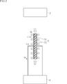
- FIG. 1 is a system configuration diagram illustrating an example of a dielectric elastomer power generation system according to the present invention. It is a figure which shows roughly the electric power generation principle of the dielectric elastomer electric power generation element of the dielectric elastomer electric power generation system of FIG. It is a figure which shows roughly the electric power generation principle of the dielectric elastomer electric power generation element of the dielectric elastomer electric power generation system of FIG.
- FIG. 1 shows an example of a dielectric elastomer power generation system according to the present invention.
- the dielectric elastomer power generation system A1 of the present embodiment includes a piezoelectric element 1, a multi-stage voltage doubler rectifier circuit 2, a dielectric elastomer power generation element 3, a power storage circuit 4, and a switch unit 5.
- the dielectric elastomer power generation system A1 is a system that generates power using vibration inputs Fv1 and Fv2.
- the piezoelectric element 1 is a so-called piezo power generation element.
- the piezoelectric element 1 has a function of converting a given vibration input into electric power.
- the piezoelectric element 1 has a characteristic that AC power can be generated by a vibration input having a relatively small amplitude.
- the multistage voltage doubler rectifier circuit 2 is a circuit that boosts and rectifies an input voltage in multiple stages and outputs a DC output voltage that is approximately an integral multiple of the input voltage.
- the multi-stage voltage doubler rectifier circuit 2 includes a Cockcroft-Walton circuit.
- the Cockcroft-Walton circuit is a circuit that performs a function of boosting the voltage in multiple stages by combining a plurality of diodes and a plurality of capacitors in multiple stages.
- the Cockcroft-Walton circuit of the multistage voltage doubler rectifier circuit 2 includes 2n diodes D1, D2,..., D2n and 2n capacitors C1, C2,. It is an assembled circuit.
- Such a multi-stage voltage doubler rectifier circuit 2 has a DC voltage n times the peak-to-peak value voltage which is the difference between the maximum value (positive peak voltage) and the minimum value (negative peak voltage) of the AC voltage which is the input voltage. Outputs voltage.
- the dielectric elastomer power generating element 3 has a dielectric elastomer layer 31 and a pair of electrode layers 32, as shown in FIGS.
- a structural member for transmitting the input external force to the dielectric elastomer power generating element 3 and a tension used for realizing the power generation operation are generated in the dielectric elastomer power generating element 3. May be appropriately provided with a tension maintaining mechanism or the like (all are not shown).
- the dielectric elastomer layer 31 is required to be elastically deformable and have high insulation strength.
- the material of the dielectric elastomer layer 31 is not particularly limited, but preferred examples include, for example, silicone elastomer and acrylic elastomer.
- the pair of electrode layers 32 sandwich the dielectric elastomer layer 31 and are portions where an initial charge is introduced and an output voltage is generated.
- the electrode layer 32 is made of a material having conductivity and capable of elastic deformation that can follow elastic deformation of the dielectric elastomer layer 31. Examples of such a material include a material obtained by mixing a filler that imparts conductivity to a main material that can be elastically deformed. Preferred examples of the filler include, for example, carbon nanotubes.
- the dielectric elastomer power generating element 3 is in a state where it is not subjected to external force or constraint, and in a state where a voltage is not applied to the pair of electrode layers 32, a natural length in which spontaneous elongation or expansion and contraction does not occur. In this state, when an external force is applied, elastic deformation of the dielectric elastomer layer 31 is allowed.
- the power storage circuit 4 receives the power generated by the dielectric elastomer power generation element 3 and is a power storage means in the dielectric elastomer power generation system A1.
- the configuration of the power storage circuit 4 is not particularly limited, as long as the power storage circuit 4 has a power storage capacity capable of appropriately storing the power generated from the dielectric elastomer power generation element 3.
- a so-called secondary battery constituting the power storage circuit 4 for example, a nickel-metal hydride battery or a lithium-ion battery can be used.
- power storage circuit 4 may include a step-down circuit that drops the input voltage to a voltage suitable for the secondary battery.
- the switch unit 5 switches the conduction state between the dielectric elastomer power generating element 3, the multi-stage voltage doubler rectifier circuit 2, and the power storage circuit 4.
- the specific configuration of the switch section 5 is not particularly limited, and may include a switch module that includes a semiconductor switch element or a switch module that switches a conductive state by a mechanical structure.
- the switch unit 5 is provided, for example, to realize the operation of the dielectric elastomer power generation system A1 described below, for example, the vibration state of the piezoelectric element 1, the voltage application state of the multi-stage voltage doubler rectifier circuit 2, and the dielectric elastomer power generation element 3.
- a detecting means for detecting any or all of the expansion and contraction state may be included.
- the switch unit 5 may include a control unit that determines the switching of the conduction state based on the detection result of the above-described detection unit and the like.
- a vibration input Fv1 is given to the piezoelectric element 1.
- the vibration input Fv1 is, for example, vibration generated by natural energy.
- the piezoelectric element 1 can generate power even with a vibration input Fv1 having a relatively small amplitude.
- the vibration input Fv1 is, for example, a vibration having a small amplitude for the power generation by the dielectric elastomer power generating element 3 or a vibration having a small amplitude for the power generation by the dielectric elastomer power generating element 3 among the vibrations whose amplitude changes in a time series. Vibration is used.
- the power obtained by the power generation of the piezoelectric element 1 is input to the multi-stage voltage doubler rectifier circuit 2.
- the power generated by the piezoelectric element 1 by the application of the vibration input Fv1 is an AC power having a peak voltage of V1.
- the voltage stored in the 2n capacitors C1, C2... C2n increases each time the polarity is switched.
- the DC voltage V2 which is the output voltage from the multi-stage voltage doubler rectifier circuit 2 becomes 2n times the voltage V1.
- the vibration input Fv2 is given to the dielectric elastomer power generation element 3.
- the multi-stage voltage doubler rectifier circuit 2 and the dielectric elastomer power generating element 3 are connected by the switching operation of the switch unit 5.
- the vibration input Fv2 for example, of the vibration having an amplitude capable of generating power by the dielectric elastomer power generating element 3 and the amplitude of generating vibration by the dielectric elastomer power generating element 3 among the vibrations whose amplitude changes in a time series.
- the vibration during the period is used. That is, as the vibration input Fv1 and the vibration input Fv2, one vibration whose amplitude changes in a time series can be used.
- the DC voltage V2 from the multi-stage voltage doubler rectifier circuit 2 is applied to the dielectric elastomer power generation element 3 in this state as an initial voltage. Specifically, by applying the DC voltage V2 to the dielectric elastomer power generating element 3 having the capacitance Cd1, the current Iq flows and the charge Q is injected.
- FIG. 3 shows a state in which the external force is weakened or becomes zero after the state shown in FIG.
- the power storage circuit 4 and the dielectric elastomer power generation element 3 are connected by the switching operation of the switch unit 5.
- the area of the dielectric elastomer layer 31 is reduced and the thickness is increased.
- the pair of electrode layers 32 follows the dielectric elastomer layer 31 and has a reduced area.
- the capacitance Cd2 is smaller than the capacitance Cd1 described above.
- the charge Q stored in the pair of electrode layers 32 is constant.
- the ratio between the voltage V3 and the DC voltage V2 is inversely proportional to the ratio between the capacitance Cd2 and the capacitance Cd1. Therefore, the output power from the pair of electrode layers 32 is received by power storage circuit 4 as output current Iw. As a result, an output power that exceeds the power required to apply the initial voltage when the dielectric elastomer layer 31 contracts can be obtained.
- This output voltage is stored in power storage circuit 4. By repeating the above operation, the electric power generated by the dielectric elastomer power generation element 3 is stored in the power storage circuit 4.
- electric power for applying an initial voltage to the dielectric elastomer power generation element 3 is generated by the piezoelectric element 1. For this reason, there is no need to use a dedicated power supply or circuit for applying an initial voltage to the dielectric elastomer power generation element 3.
- the AC voltage from the piezoelectric element 1 is boosted and rectified by the multi-stage voltage doubler rectifier circuit, and then applied to the dielectric elastomer power generation element as an initial voltage.
- the power generation amount of the dielectric elastomer power generating element 3 can be improved. Therefore, the power generation amount can be improved while reducing the system construction cost of the dielectric elastomer power generation system.
- the multi-stage voltage doubler rectifier circuit 2 includes a Cockcroft-Walton circuit
- the multi-stage voltage doubler rectifier circuit 2 can be constituted by a plurality of diodes and a plurality of capacitors. Further, since the voltage at each stage is equal to the peak-to-peak voltage of the AC voltage which is the input voltage, it is not necessary to use a diode or a capacitor having an extremely high withstand voltage. Further, boosting and rectification can be realized by one multi-stage voltage doubler rectifier circuit 2, and the number of components of the dielectric elastomer power generation system A1 can be reduced. Therefore, the multi-stage voltage doubler rectifier circuit 2 can be configured at lower cost. Further, since the mean time between failures can be improved, a more reliable dielectric elastomer power generation system A1 can be constructed.
- the dielectric elastomer power generation system according to the present invention is not limited to the above embodiment.
- the specific configuration of each part of the dielectric elastomer power generation system according to the present invention can be variously changed in design.
Landscapes
- Engineering & Computer Science (AREA)
- Power Engineering (AREA)
- General Electrical Machinery Utilizing Piezoelectricity, Electrostriction Or Magnetostriction (AREA)
- Rectifiers (AREA)
Abstract
誘電エラストマー発電システムA1は、誘電エラストマー層31および当該誘電エラストマー層31を挟む一対の電極層32を有する誘電エラストマー発電要素3を備える。誘電エラストマー発電システムA1はさらに、圧電素子1と、圧電素子1によって発電された電圧を昇圧し且つ整流するとともに誘電エラストマー発電要素3に初期印加電荷として与える多段倍電圧整流回路2と、を備える。このような構成により、システム構築コストを低減しつつ発電量を向上させることができる。
Description
本発明は、誘電エラストマー発電システムに関する。
誘電エラストマー層と当該誘電エラストマー層を挟む一対の電極層とを有する誘電エラストマー要素は、駆動用途および発電用途のそれぞれの分野において開発が進められている。特許文献1,2には、誘電エラストマー要素が発電用途に用いられた誘電エラストマー発電システムが開示されている。この誘電エラストマー発電システムにおいては、誘電エラストマー要素を伸長させる外力(力学的エネルギー)を電気的エネルギーに変換することにより発電がなされている。この発電による電力は、たとえばニッケル水素電池およびリチウムイオン電池や電気二重層コンデンサ等の二次電池に蓄電される。
誘電エラストマー要素を用いた発電の原理は、誘電エラストマー要素に外力が与えられることによる静電容量の変化を利用して、初期印加電荷による電圧(以下、初期電圧)よりも高い電圧を得るものである。誘電エラストマー発電システムの発電量を向上させるには、より高い初期電圧を誘電エラストマー要素に与えることが好ましい。このような初期電圧を与えるために、たとえば専用の電源回路が必要となり、誘電エラストマー発電システムの煩雑化、高コスト化を招来する。
本発明は、上記した事情のもとで考え出されたものであって、システム構築コストを低減しつつ発電量を向上させることが可能な誘電エラストマー発電システムを提供することをその課題とする。
本発明によって提供される誘電エラストマー発電システムは、誘電エラストマー層および当該誘電エラストマー層を挟む一対の電極層を有する誘電エラストマー発電要素を備え、圧電素子と、前記圧電素子によって発電された電圧を昇圧し且つ整流するとともに前記誘電エラストマー発電要素に初期印加電荷として与える多段倍電圧整流回路と、を備える。
本発明の好ましい実施の形態においては、前記多段倍電圧整流回路は、コッククロフト・ウォルトン回路を含む。
本発明によれば、システム構築コストを低減しつつ発電量を向上させることができる。
本発明のその他の特徴および利点は、添付図面を参照して以下に行う詳細な説明によって、より明らかとなろう。
以下、本発明の好ましい実施の形態につき、図面を参照して具体的に説明する。
図1は、本発明に係る誘電エラストマー発電システムの一例を示している。本実施形態の誘電エラストマー発電システムA1は、圧電素子1、多段倍電圧整流回路2、誘電エラストマー発電要素3、蓄電回路4およびスイッチ部5を備える。誘電エラストマー発電システムA1は、振動入力Fv1,Fv2を利用して発電を行うシステムである。
圧電素子1は、いわゆるピエゾ発電素子である。圧電素子1は、与えられた振動入力を電力に変換する機能を果たす。圧電素子1は、比較的振幅が小さい振動入力によって交流電力を発電可能であるという特性を有する。
多段倍電圧整流回路2は、入力電圧を多段倍に昇圧し且つ整流することにより、入力電圧の略整数倍の直流の出力電圧を出力する回路である。本実施形態においては、多段倍電圧整流回路2は、コッククロフト・ウォルトン回路を含む。コッククロフト・ウォルトン回路は、複数のダイオードと、複数のコンデンサとが多段に組み合わされることにより、多段倍に昇圧する機能を果たす回路である。図示された例においては、多段倍電圧整流回路2のコッククロフト・ウォルトン回路は、2n個のダイオードD1,D2・・・D2nと、2n個のコンデンサC1,C2・・・C2nと、がn段に組まれた回路である。このような多段倍電圧整流回路2は、入力電圧である交流電圧の最大値(正側のピーク電圧)と最小値(負側のピーク電圧)の差であるピークピーク値電圧のn倍の直流電圧を出力する。
誘電エラストマー発電要素3は、図2および図3に示すように、誘電エラストマー層31および一対の電極層32を有する。なお、誘電エラストマー発電要素3に加えて、入力された外力を誘電エラストマー発電要素3に伝達するための構造部材や、発電動作を実現する上で利用される張力を誘電エラストマー発電要素3に発生させるための張力維持機構等(いずれも図示略)を適宜備えていてもよい。
誘電エラストマー層31は、弾性変形が可能であるとともに、絶縁強度が高いことが求められる。このような誘電エラストマー層31の材質は特に限定されないが、好ましい例として、たとえばシリコーンエラストマーやアクリルエラストマーが挙げられる。
一対の電極層32は、誘電エラストマー層31を挟んでおり、初期電荷が導入され、出力電圧が生じる部位である。電極層32は、導電性を有するとともに、誘電エラストマー層31の弾性変形に追従しうる弾性変形が可能な材質によって形成される。このような材質としては、弾性変形可能な主材に導電性を付与するフィラーが混入された材質が挙げられる。前記フィラーの好ましい例として、たとえばカーボンナノチューブが挙げられる。
誘電エラストマー発電要素3は、外部からの外力や拘束を受けていない状態であって、一対の電極層32に電圧が印加されていない状態においては、自発的な伸長や伸縮を生じていない自然長状態にあり、外力が付与された場合に、誘電エラストマー層31の弾性変形が許容されている。
蓄電回路4は、誘電エラストマー発電要素3によって発電された電力が入力されるものであり、誘電エラストマー発電システムA1における蓄電手段である。蓄電回路4の構成は特に限定されず、誘電エラストマー発電要素3から発電される電力を適切に蓄電可能な蓄電容量を備えたものであればよい。蓄電回路4を構成する所謂二次電池としては、たとえばニッケル水素電池やリチウムイオン電池が挙げられる。また、蓄電回路4は、入力電圧を二次電池に適した電圧に降下させる降圧回路を備えていてもよい。
スイッチ部5は、誘電エラストマー発電要素3と多段倍電圧整流回路2および蓄電回路4との導通状態を切り替えるものである。スイッチ部5の具体的構成は特に限定されず、半導体スイッチ素子を含むものや、機械的な構造によって導通状態を切り替えるスイッチモジュールを含むものであってもよい。さらに、スイッチ部5は、以下に述べる誘電エラストマー発電システムA1の動作を実現するために、たとえば圧電素子1の振動状態や、多段倍電圧整流回路2の電圧印加状態、および誘電エラストマー発電要素3の伸縮状態のいずれかまたはすべてを検出する検出手段を含んでいてもよい。また、スイッチ部5は、上述の検出手段の検出結果等に基づいて、導通状態の切り替えを判断する制御部を含んでいてもよい。
次に、誘電エラストマー発電システムA1の動作例について、以下に説明する。
図1に示すように、圧電素子1に振動入力Fv1が与えられる。振動入力Fv1は、たとえば自然エネルギーによって生じる振動である。圧電素子1は、比較的小さい振幅の振動入力Fv1であっても発電可能である。このため、振動入力Fv1としては、たとえば誘電エラストマー発電要素3による発電には振幅が小さい振動や、時系列で振幅が変化する振動のうち、誘電エラストマー発電要素3による発電には振幅が小さい期間の振動が用いられる。
圧電素子1の発電によって得られた電力は、多段倍電圧整流回路2に入力される。振動入力Fv1が与えられることにより圧電素子1で発電された電力は、ピーク電圧が電圧V1の交流電力である。この交流電力が多段倍電圧整流回路2に入力されると、電圧の正負が入れ替わるたびに、2n個のコンデンサC1,C2・・・C2nに蓄電される電圧が高くなる。たとえば、振動入力Fv1による圧電素子1からの交流電圧が十分に入力されると、多段倍電圧整流回路2からの出力電圧である直流電圧V2は、電圧V1の2n倍となる。
次いで、図1に示すように、誘電エラストマー発電要素3には、振動入力Fv2が与えられる。同図においては、スイッチ部5の切り替え動作により、多段倍電圧整流回路2と誘電エラストマー発電要素3とが接続されている。振動入力Fv2としては、たとえば誘電エラストマー発電要素3による発電が可能な程度の振幅を有する振動や、時系列で振幅が変化する振動のうち、誘電エラストマー発電要素3による発電が可能な程度の振幅を有する期間の振動が用いられる。すなわち、振動入力Fv1と振動入力Fv2としては、時系列で振幅が変化する1つの振動を利用することができる。
図2においては、誘電エラストマー発電要素3に、振動入力Fv1によって図中上下方向に向かう外力が負荷されている。このため、誘電エラストマー発電要素3の誘電エラストマー層31が、図中上下方向に伸長されている。これにより、誘電エラストマー層31の面積が増大し、厚さが縮小している。一対の電極層32は、誘電エラストマー層31に追従しており、面積が拡大している。この状態において、誘電エラストマー発電要素3をコンデンサとしてとらえた場合、その静電容量Cd1は、相対的に大となっている。この状態の誘電エラストマー発電要素3に、多段倍電圧整流回路2からの直流電圧V2を初期電圧として印加する。具体的には、静電容量Cd1の誘電エラストマー発電要素3に直流電圧V2を印加することにより、電流Iqが流れ、電荷Qが投入される。
図3は、図2に示す状態の後に、上記外力が弱められ、あるいはゼロとなることにより、図2に示す状態から誘電エラストマー発電要素3が縮小した状態を示している。同図においては、スイッチ部5の切り替え動作により、蓄電回路4と誘電エラストマー発電要素3とが接続されている。この状態においては、誘電エラストマー層31の面積が縮小し、厚さが増大している。一対の電極層32は、誘電エラストマー層31に追従しており、面積が縮小している。この状態において、誘電エラストマー発電要素3をコンデンサとしてとらえた場合、その静電容量Cd2は、上述した静電容量Cd1よりも小となっている。しかし、一対の電極層32に蓄えられた電荷Qは、一定である。このため、電圧V3と直流電圧V2との比は、静電容量Cd2と静電容量Cd1との比と、反比例の関係にある。したがって、一対の電極層32からの出力電力を蓄電回路4によって出力電流Iwとして受電する。これにより、誘電エラストマー層31の収縮時に初期電圧の印加に要する電力を上回る出力電力が得られる。この出力電圧は、蓄電回路4に蓄電される。以上の動作を繰り返すことにより、誘電エラストマー発電要素3によって発電された電力を、蓄電回路4に蓄電する。
次に、誘電エラストマー発電システムA1の作用について説明する。
本実施形態によれば、誘電エラストマー発電要素3に初期電圧を印加するための電力は、圧電素子1によって発電される。このため、誘電エラストマー発電要素3に初期電圧を印加するための専用の電源や回路等を用いる必要がない。また、圧電素子1からの交流電圧は、多段倍電圧整流回路によって昇圧および整流された後に、誘電エラストマー発電要素に初期電圧として印加される。誘電エラストマー発電要素3が発電機能を果たす範囲において、印加される初期電圧が高いほど、誘電エラストマー発電要素3の発電量を向上させることが可能である。したがって、誘電エラストマー発電システムのシステム構築コストを低減しつつ、発電量を向上させることができる。
また、多段倍電圧整流回路2が、コッククロフト・ウォルトン回路を含むため、多段倍電圧整流回路2を複数のダイオードおよび複数のコンデンサによって構成することが可能である。また、各段における電圧は、入力電圧である交流電圧のピークピーク値電圧の等倍であるため、ダイオードやコンデンサとして、極端に耐圧が高いものを用いる必要がない。また、昇圧および整流を、1つの多段倍電圧整流回路2によって実現可能であり、誘電エラストマー発電システムA1の部品点数を削減することができる。したがって、多段倍電圧整流回路2をより低コストで構成可能である。また、平均故障間隔を向上できることから、より信頼性の高い誘電エラストマー発電システムA1を構築可能である。
本発明に係る誘電エラストマー発電システムは、上述した実施形態に限定されるものではない。本発明に係る誘電エラストマー発電システムの各部の具体的な構成は、種々に設計変更自在である。
Claims (2)
- 誘電エラストマー層および当該誘電エラストマー層を挟む一対の電極層を有する誘電エラストマー発電要素を備え、
圧電素子と、
前記圧電素子によって発電された電圧を昇圧し且つ整流するとともに前記誘電エラストマー発電要素に初期印加電荷として与える多段倍電圧整流回路と、を備える、誘電エラストマー発電システム。 - 前記多段倍電圧整流回路は、コッククロフト・ウォルトン回路を含む、請求項1に記載の誘電エラストマー発電システム。
Priority Applications (4)
| Application Number | Priority Date | Filing Date | Title |
|---|---|---|---|
| CN201980050227.8A CN112514235A (zh) | 2018-08-09 | 2019-07-10 | 介电弹性体发电系统 |
| US17/264,845 US11909337B2 (en) | 2018-08-09 | 2019-07-10 | Dielectric elastomer power generation system |
| EP19846663.3A EP3836385A4 (en) | 2018-08-09 | 2019-07-10 | Dielectric elastomer power generation system |
| JP2020536398A JPWO2020031600A1 (ja) | 2018-08-09 | 2019-07-10 | 誘電エラストマー発電システム |
Applications Claiming Priority (2)
| Application Number | Priority Date | Filing Date | Title |
|---|---|---|---|
| JP2018-150278 | 2018-08-09 | ||
| JP2018150278 | 2018-08-09 |
Publications (1)
| Publication Number | Publication Date |
|---|---|
| WO2020031600A1 true WO2020031600A1 (ja) | 2020-02-13 |
Family
ID=69415557
Family Applications (1)
| Application Number | Title | Priority Date | Filing Date |
|---|---|---|---|
| PCT/JP2019/027307 Ceased WO2020031600A1 (ja) | 2018-08-09 | 2019-07-10 | 誘電エラストマー発電システム |
Country Status (5)
| Country | Link |
|---|---|
| US (1) | US11909337B2 (ja) |
| EP (1) | EP3836385A4 (ja) |
| JP (1) | JPWO2020031600A1 (ja) |
| CN (1) | CN112514235A (ja) |
| WO (1) | WO2020031600A1 (ja) |
Families Citing this family (5)
| Publication number | Priority date | Publication date | Assignee | Title |
|---|---|---|---|---|
| JP7015747B2 (ja) * | 2018-07-30 | 2022-02-03 | 正毅 千葉 | 誘電エラストマートランスデューサーシステム |
| JP6800928B2 (ja) * | 2018-09-27 | 2020-12-16 | 正毅 千葉 | 誘電エラストマー振動システムおよび電源装置 |
| WO2020175257A1 (ja) * | 2019-02-28 | 2020-09-03 | 正毅 千葉 | 誘電エラストマー発電システム |
| CN113595433B (zh) * | 2021-07-08 | 2023-04-18 | 浙江师范大学 | 一种介电弹性体能量收集系统和方法 |
| CN115284269A (zh) * | 2022-01-18 | 2022-11-04 | 浙江师范大学 | 一种仿生自驱动静电执行系统 |
Citations (5)
| Publication number | Priority date | Publication date | Assignee | Title |
|---|---|---|---|---|
| JPS559350B2 (ja) | 1975-10-07 | 1980-03-10 | ||
| JP5479659B2 (ja) | 2000-02-23 | 2014-04-23 | エスアールアイ インターナショナル | 生体によって動力を供給される電気活性ポリマジェネレータ |
| JP2014128161A (ja) * | 2012-12-27 | 2014-07-07 | Taiheiyo Cement Corp | 発電回路およびこれを用いた発信装置 |
| JP2015211601A (ja) * | 2014-04-30 | 2015-11-24 | 日置電機株式会社 | 電圧生成回路 |
| JP2018019490A (ja) * | 2016-07-27 | 2018-02-01 | 正毅 千葉 | 誘電エラストマー発電装置 |
Family Cites Families (8)
| Publication number | Priority date | Publication date | Assignee | Title |
|---|---|---|---|---|
| US8643253B1 (en) * | 2007-09-03 | 2014-02-04 | Joseph Anthony Micallef | Piezoelectric ultracapacitors |
| JP5826192B2 (ja) * | 2010-02-24 | 2015-12-02 | オークランド・ユニサービシス・リミテッド | 電気コンポーネントおよび前記コンポーネントを含む回路 |
| JP2012228069A (ja) * | 2011-04-19 | 2012-11-15 | Panasonic Corp | 床装置およびこれに用いられる床パネル |
| CN202110953U (zh) * | 2011-05-25 | 2012-01-11 | 四川云翔电子科技有限公司 | 新型薄膜电容器 |
| KR20130042984A (ko) * | 2011-10-19 | 2013-04-29 | 김광하 | 강제진동을 이용한 독립전원 및 발전 시스템 |
| DK2847856T3 (en) | 2012-05-10 | 2018-08-06 | Single Buoy Moorings | Charging / Discharging Circuits for Electromechanical Energy Conversion and Electromechanical Energy Conversion System |
| JP2016073366A (ja) | 2014-10-03 | 2016-05-12 | 克弥 西沢 | 歩行による発電機能と無線通信および測位機能を備えた無線通信機および無線通信機を中敷として用いた歩行者の位置監視システム |
| US10250235B2 (en) * | 2015-11-30 | 2019-04-02 | The Regents Of The University Of Michigan | Full-wave charge pump with low-voltage startup |
-
2019
- 2019-07-10 WO PCT/JP2019/027307 patent/WO2020031600A1/ja not_active Ceased
- 2019-07-10 US US17/264,845 patent/US11909337B2/en active Active
- 2019-07-10 CN CN201980050227.8A patent/CN112514235A/zh active Pending
- 2019-07-10 EP EP19846663.3A patent/EP3836385A4/en not_active Withdrawn
- 2019-07-10 JP JP2020536398A patent/JPWO2020031600A1/ja not_active Ceased
Patent Citations (5)
| Publication number | Priority date | Publication date | Assignee | Title |
|---|---|---|---|---|
| JPS559350B2 (ja) | 1975-10-07 | 1980-03-10 | ||
| JP5479659B2 (ja) | 2000-02-23 | 2014-04-23 | エスアールアイ インターナショナル | 生体によって動力を供給される電気活性ポリマジェネレータ |
| JP2014128161A (ja) * | 2012-12-27 | 2014-07-07 | Taiheiyo Cement Corp | 発電回路およびこれを用いた発信装置 |
| JP2015211601A (ja) * | 2014-04-30 | 2015-11-24 | 日置電機株式会社 | 電圧生成回路 |
| JP2018019490A (ja) * | 2016-07-27 | 2018-02-01 | 正毅 千葉 | 誘電エラストマー発電装置 |
Non-Patent Citations (1)
| Title |
|---|
| See also references of EP3836385A4 |
Also Published As
| Publication number | Publication date |
|---|---|
| EP3836385A4 (en) | 2022-05-04 |
| US20210297013A1 (en) | 2021-09-23 |
| CN112514235A (zh) | 2021-03-16 |
| JPWO2020031600A1 (ja) | 2021-09-24 |
| EP3836385A1 (en) | 2021-06-16 |
| US11909337B2 (en) | 2024-02-20 |
Similar Documents
| Publication | Publication Date | Title |
|---|---|---|
| US11909337B2 (en) | Dielectric elastomer power generation system | |
| Ardi et al. | Study on a high voltage gain SEPIC-based DC–DC converter with continuous input current for sustainable energy applications | |
| US7138730B2 (en) | Topologies for multiple energy sources | |
| KR102113936B1 (ko) | 마찰식 나노 발전기의 에너지 관리 방법, 회로 및 장치 | |
| Mostaan et al. | A trans-inverse coupled-inductor semi-SEPIC DC/DC converter with full control range | |
| JP2016127656A (ja) | 環境発電素子で発生した電力を蓄電する蓄電装置 | |
| Ram et al. | Ultra-low power solar energy harvester for IoT edge node devices | |
| US9948172B2 (en) | Power converter for eliminating ripples | |
| Kularatna et al. | Supercapacitor energy storage in solar application: A design approach to minimize a fundamental loss issue by partitioning the load and the storage device | |
| Wang et al. | A high step-up voltage gain DC/DC converter for the micro-inverter | |
| JP4370965B2 (ja) | 電力変換装置 | |
| US11218091B2 (en) | Dielectric elastomer power generation system | |
| Bondarenko et al. | Direct energy and energy storage circuit topologies of DC power supplies for micro resistance welding | |
| WO2020026824A1 (ja) | 誘電エラストマートランスデューサーシステム | |
| JP5586096B2 (ja) | 電力変換装置 | |
| JP2009273201A (ja) | 電場応答性高分子を用いた発電装置 | |
| Siwakoti et al. | A novel quasi-SEPIC high-voltage boost DC-DC converter | |
| Zhang et al. | High-voltage MEMS plasma switch for boosting the energy transfer efficiency in triboelectric nanogenerators | |
| JP6618184B2 (ja) | 高電圧発生装置 | |
| JP5278568B2 (ja) | 半導体スイッチング素子駆動用電源回路 | |
| JP4516587B2 (ja) | 蓄電回路 | |
| WO2012032651A1 (ja) | 蓄電モジュールの過電圧検出装置 | |
| Basset et al. | High-voltage micro-plasma switch for efficient power management of triboelectric kinetic energy harvesters | |
| de Melo Bento et al. | Study of High Step-up Non-isolated DC-DC Converters | |
| US20220165932A1 (en) | Dielectric elastomer power generation system |
Legal Events
| Date | Code | Title | Description |
|---|---|---|---|
| 121 | Ep: the epo has been informed by wipo that ep was designated in this application |
Ref document number: 19846663 Country of ref document: EP Kind code of ref document: A1 |
|
| ENP | Entry into the national phase |
Ref document number: 2020536398 Country of ref document: JP Kind code of ref document: A |
|
| NENP | Non-entry into the national phase |
Ref country code: DE |
|
| ENP | Entry into the national phase |
Ref document number: 2019846663 Country of ref document: EP Effective date: 20210309 |