WO2020031645A1 - 通信装置、通信方法及び記録媒体 - Google Patents
通信装置、通信方法及び記録媒体 Download PDFInfo
- Publication number
- WO2020031645A1 WO2020031645A1 PCT/JP2019/028173 JP2019028173W WO2020031645A1 WO 2020031645 A1 WO2020031645 A1 WO 2020031645A1 JP 2019028173 W JP2019028173 W JP 2019028173W WO 2020031645 A1 WO2020031645 A1 WO 2020031645A1
- Authority
- WO
- WIPO (PCT)
- Prior art keywords
- beam group
- information
- commonality
- communication device
- measurement result
- Prior art date
- Legal status (The legal status is an assumption and is not a legal conclusion. Google has not performed a legal analysis and makes no representation as to the accuracy of the status listed.)
- Ceased
Links
Images


Classifications
-
- H—ELECTRICITY
- H04—ELECTRIC COMMUNICATION TECHNIQUE
- H04W—WIRELESS COMMUNICATION NETWORKS
- H04W24/00—Supervisory, monitoring or testing arrangements
- H04W24/10—Scheduling measurement reports ; Arrangements for measurement reports
-
- H—ELECTRICITY
- H04—ELECTRIC COMMUNICATION TECHNIQUE
- H04B—TRANSMISSION
- H04B7/00—Radio transmission systems, i.e. using radiation field
- H04B7/02—Diversity systems; Multi-antenna system, i.e. transmission or reception using multiple antennas
- H04B7/04—Diversity systems; Multi-antenna system, i.e. transmission or reception using multiple antennas using two or more spaced independent antennas
- H04B7/06—Diversity systems; Multi-antenna system, i.e. transmission or reception using multiple antennas using two or more spaced independent antennas at the transmitting station
- H04B7/0686—Hybrid systems, i.e. switching and simultaneous transmission
- H04B7/0691—Hybrid systems, i.e. switching and simultaneous transmission using subgroups of transmit antennas
-
- H—ELECTRICITY
- H04—ELECTRIC COMMUNICATION TECHNIQUE
- H04W—WIRELESS COMMUNICATION NETWORKS
- H04W16/00—Network planning, e.g. coverage or traffic planning tools; Network deployment, e.g. resource partitioning or cells structures
- H04W16/24—Cell structures
- H04W16/28—Cell structures using beam steering
-
- H—ELECTRICITY
- H04—ELECTRIC COMMUNICATION TECHNIQUE
- H04W—WIRELESS COMMUNICATION NETWORKS
- H04W68/00—User notification, e.g. alerting and paging, for incoming communication, change of service or the like
- H04W68/005—Transmission of information for alerting of incoming communication
Definitions
- the present disclosure relates to a communication device, a communication method, and a recording medium.
- LTE Long Term Evolution
- LTE-A Long Term Evolution
- LTE-A Pro LTE-Advanced Pro
- 5G 5 generations
- NR New Radio
- NRAT New Radio Access Technology
- EUTRA Evolved Universal Terrestrial Radio Access
- FEUTRA Frether EUTRA
- LTE and NR a base station device (base station) is also called eNodeB (evolved @ NodeB) in LTE and gNodeB in NR, and a terminal device (mobile station, mobile station device, terminal) is also called UE (User @ Equipment).
- eNodeB evolved @ NodeB
- UE User @ Equipment
- LTE and NR are cellular communication systems in which a plurality of areas covered by a base station are arranged in a cell. A single base station may manage multiple cells.
- a component carrier (Component Carrier: CC) can be used by being divided into a plurality of frequency bandwidth parts (Bandwidth Part: BWP).
- BWP Bandwidth Part
- Patent Literature 1 below discloses a technique of feeding back a PMI (Precoding Matrix Indicator) for each BWP.
- the procedure for selecting an optimum beam to be used for communication it is considered to perform beam sweeping for transmitting or receiving a measurement signal (known signal) using each of a plurality of beams belonging to a beam group.
- a measurement signal known signal
- performing a beam selection procedure in a plurality of frequency bandwidths is a burden on the terminal device.
- the present disclosure provides a mechanism capable of reducing a load on a beam selection procedure in a plurality of frequency bandwidths.
- a setting unit that sets a beam group defined in each of a plurality of frequency bandwidths, and notifies a terminal device of information on commonality between the beam groups defined in different frequency bandwidths. And a notifying unit.
- a communication device comprising: a measurement report unit that measures a measurement signal transmitted by beam sweeping using the beam group by the other communication device based on information, and reports a measurement result.
- setting of a beam group defined in each of a plurality of frequency bandwidths, and information regarding commonality between the beam groups defined in different frequency bandwidths is transmitted to a terminal device.
- the commonality between the beam groups defined in different frequency bandwidths Measuring a measurement signal beam-sweeped by the other communication device using the beam group based on the information, and reporting a measurement result.
- a setting unit configured to set a beam group defined in each of a plurality of frequency bandwidths, and information on commonality between the beam groups defined in different frequency bandwidths And a recording medium on which a program for causing the terminal device to function as a notifying unit is recorded.
- a computer is notified from another communication device, and for a beam group defined in each of a plurality of frequency bandwidths, the beam groups defined in different frequency bandwidths are different from each other.
- a program for functioning as a measurement reporting unit that measures the measurement signal transmitted by beam sweeping using the beam group by the other communication device and reports the measurement result is recorded.
- the provided recording medium is provided.
- a mechanism capable of reducing a load on a beam selection procedure in a plurality of frequency bandwidths is provided. Note that the above effects are not necessarily limited, and any of the effects shown in the present specification or other effects that can be grasped from the present specification are used together with or in place of the above effects. May be played.
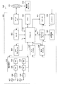
- FIG. 1 is a diagram illustrating an example of an overall configuration of a system according to an embodiment of the present disclosure. It is a figure for explaining BWP. It is a figure for explaining beam sweeping.
- FIG. 11 is a sequence diagram illustrating an example of a flow of a typical measurement report process executed by a base station and a terminal device. It is a block diagram showing an example of the composition of the base station concerning the embodiment. It is a block diagram showing an example of composition of a terminal unit concerning the embodiment.
- FIG. 4 is a diagram for describing an outline of commonality information according to the first embodiment. It is a figure for explaining the example in the case where all the beams which belong to a beam group are common.
- FIG. 9 is a diagram for describing a specific example in a case where a subset of a beam group is common.
- FIG. 3 is a diagram for describing an example of commonality information according to the embodiment.
- FIG. 3 is a diagram for describing an example of commonality information according to the embodiment. It is a figure for explaining a technical subject of a 2nd embodiment. It is a figure for explaining an example of the linkage of the beam sweeping using a plurality of beam groups concerning the embodiment. It is a sequence which shows an example of the flow of the beam selection processing performed by the system concerning the embodiment.
- FIG. 4 is a block diagram illustrating a first example of a schematic configuration of an eNB. It is a block diagram which shows the 2nd example of a schematic structure of eNB. It is a block diagram which shows an example of a schematic structure of a smart phone. It is a block diagram showing an example of a schematic structure of a car navigation device.
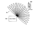
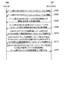
- FIG. 1 is a diagram illustrating an example of an overall configuration of a system 1 according to an embodiment of the present disclosure.
- the system 1 includes a base station 100 (100A and 100B), a terminal device 200 (200A and 200B), a core network (Core Network) 20, and a PDN (Packet Data Network) 30.
- a base station 100 100A and 100B
- a terminal device 200 200A and 200B
- a core network Core Network
- PDN Packet Data Network
- the base station 100 is a communication device that operates the cell 11 (11A and 11B) and provides a wireless service to one or more terminal devices located inside the cell 11.
- the base station 100A provides a wireless service to the terminal device 200A
- the base station 100B provides a wireless service to the terminal device 200B.
- the cell 11 can be operated according to any wireless communication scheme such as LTE or NR (New Radio).
- the base station 100 is connected to the core network 20.
- the core network 20 is connected to the PDN 30.
- the core network 20 may include, for example, an MME (Mobility Management Entity), an S-GW (Serving PDgateway), a P-GW (PDN (gateway), a PCRF (Policy and Charging Rule Function), and an HSS (Home Subscriber Server).
- the MME is a control node that handles signals of the control plane, and manages a moving state of the terminal device.
- the S-GW is a control node that handles user plane signals, and is a gateway device that switches a user data transfer path.
- the P-GW is a control node that handles user plane signals, and is a gateway device serving as a connection point between the core network 20 and the PDN 30.
- the PCRF is a control node that controls policies such as QoS (Quality of Service) and charging for bearers.
- the HSS is a control node that handles subscriber data and performs service control.
- the terminal device 200 is a communication device that performs wireless communication with the base station 100 based on control by the base station 100.
- the terminal device 200 may be a so-called user terminal (User @ Equipment: UE).
- the terminal device 200 transmits an uplink signal to the base station 100 and receives a downlink signal from the base station 100.
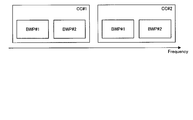
- FIG. 2 is a diagram for explaining BWP.
- CC # 1 includes a plurality of BWPs (# 1 and # 2)
- CC # 2 includes a plurality of BWPs (# 1 and # 2).
- the number after # indicates an index.
- BWPs included in different CCs indicate different BWPs even if the index is the same.
- BWP is obtained by dividing CC which is one operation frequency bandwidth (operation band width) into a plurality of frequency bandwidths. In each BWP, a different subcarrier spacing can be set.
- This BWP has been standardized as a basic frame format of NR of 3GPP Rel15.
- the subcarrier interval was fixed at 15 kHz.
- the subcarrier interval can be set to 60 kHz, 120 kHz or 240 kHz. The longer the subcarrier interval, the shorter the OFDM symbol length. For example, in LTE, since the subcarrier interval is 15 kHz, one slot can be transmitted per 1 ms, in other words, 14 OFDM symbols can be transmitted.
- two slots can be transmitted when the subcarrier interval is 60 kHz, four slots when the subcarrier interval is 120 kHz, and eight slots when the subcarrier interval is 240 kHz.
- the OFDM symbol length is reduced. Accordingly, it is possible to provide a frame configuration suitable for low-delay communication.
- BWP with different subcarrier intervals can be provided simultaneously. Therefore, the NR can simultaneously provide a plurality of BWPs corresponding to different use cases.
- a BWP capable of transmitting and receiving is also called an active BWP.
- the number of BWPs that can transmit and receive at the same time is also called the number of active BWPs.
- the number of active BWPs of the base station 100 is plural.
- the number of active BWPs of the terminal device 200 may be one.
- the terminal device 200 having a plurality of active BWPs is expected to appear in the future. These scenarios are shown in Table 1 below.
- the technology according to the present disclosure can be applied to both the case where the number of active BWPs of the terminal device 200 is one and the case where the number of active BWPs is plural.
- the base station 100 can improve communication quality by performing beamforming and communicating with the terminal device 200, for example.
- a beamforming method there are a method of generating a beam that follows the terminal device 200 and a method of selecting a beam that follows the terminal device 200 from candidate beams.
- the former method is computationally expensive every time a beam is generated, and thus it is unlikely that the former method will be adopted in a future wireless communication system (for example, 5G).
- the latter method is also adopted in FD-MIMO (Full Dimension Multiple Input Multiple Output) of Release 13 of 3GPP (Third Generation Partnership Project).
- the latter method is also called codebook based beam forming.
- the base station 100 prepares (or generates) beams in all directions in advance, and selects a beam suitable for the target terminal device 200 from among the beams prepared in advance. And communicates with the terminal device 200 using the selected beam. For example, when communication at 360 degrees in the horizontal direction is possible, the base station 100 prepares, for example, 360 types of beams at intervals of 1 degree. When making the beams overlap by half, the base station 100 prepares 720 types of beams. In the vertical direction, the base station 100 prepares a beam for 180 degrees, for example, from -90 degrees to +90 degrees.
- the terminal device 200 since the terminal device 200 only observes the beam, it is not necessary to know the existence of the codebook on the base station 100 side.
- a plurality of beams prepared by the base station 100 in advance are also referred to as beam groups below.
- the beam group can be defined for each frequency band, for example. Also, beams may be defined for each Rx / Tx beam and for each downlink / uplink.
- the measurement signal may also be referred to as a reference signal (Reference Signal). It is possible to select an optimal transmission signal (hereinafter also referred to as a Tx beam) based on the measurement result of the measurement signal transmitted while performing beam sweeping.
- a Tx beam an optimal transmission signal
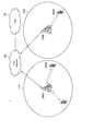
- FIG. 3 is a diagram for explaining beam sweeping.
- the base station 100 transmits the measurement signal while performing beam sweeping using the beam group 40 (that is, switching the Tx beam).
- the transmission while performing beam sweeping is hereinafter also referred to as beam sweeping transmission.
- terminal apparatus 200 measures the measurement signal transmitted by beam sweeping, and determines which Tx beam is most easily received. In this way, the optimal Tx beam of the base station 100 is selected.
- the base station 100 can select the optimal Tx beam of the terminal device 200 by exchanging the base station 100 and the terminal device 200 and performing the same procedure.
- an optimal receiving beam (hereinafter, also referred to as an Rx beam) can be selected based on a measurement result obtained by receiving the measuring signal while beam sweeping.
- the terminal device 200 transmits the measurement signal on the uplink.
- base station 100 receives the measurement signal while performing beam sweeping (that is, while switching Rx beams), and determines which Rx beam is most easily received.
- the optimal Rx beam of the base station 100 is selected.
- the terminal device 200 can select the optimal Rx beam of the terminal device 200.
- receiving while performing beam sweeping is also referred to as beam sweeping reception below.
- the side that receives and measures the measurement signal transmitted by beam sweeping reports the measurement result to the transmission side of the measurement signal.
- the measurement result includes information indicating which Tx beam is optimal.
- the optimal Tx beam is, for example, a Tx beam having the highest received power.
- the measurement result may include information indicating one Tx beam with the highest received power, or may include information indicating the top K Tx beams with the highest received power.
- the measurement result includes, for example, Tx beam identification information (eg, beam index) and information indicating the magnitude of the received power of the Tx beam (eg, RSRP (Reference ⁇ Signal ⁇ Received ⁇ Power)) in association with each other.
- Tx beam identification information eg, beam index
- RSRP Reference ⁇ Signal ⁇ Received ⁇ Power
- the measurement signal is transmitted by beam sweeping using each of the plurality of Tx beams belonging to the beam group. It can be said that each of the Tx beams is identified by a resource called a measurement signal.
- the measurement signal transmitted using the beam may be referred to as a beam resource. Further, the measurement signal transmitted by beam sweeping using the beam group may be referred to as a beam resource group.
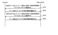
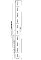
- FIG. 4 is a sequence diagram showing an example of a flow of a typical measurement report process executed by the base station and the terminal device.
- the base station beam-sweep-transmits the measurement signal using BWP # 1 beam group # 1 in BWP # 1 (step S12).
- the terminal device measures the measurement signal transmitted by beam sweeping transmission using beam group # 1 in BWP # 1, and reports the measurement result to the base station (step S14).
- the base station transmits a signal for measurement by beam sweeping using beam group # 2 for BWP # 2 (step S16).
- the terminal device performs measurement of the measurement signal transmitted by beam sweeping using beam group # 2 in BWP # 2, and reports the measurement result to the base station (step S18).
- TS38.214 stipulates that the base station transmits information indicating whether or not different reference signals may be considered to have been transmitted from the same base station. . More specifically, it is stipulated that the base station transmits information indicating whether or not the antenna ports # 0 and # 1 transmit beams in the same direction. However, such information merely indicates the relationship of beams between antenna ports, and is not information indicating the relationship of beams between different BWPs or between different CCs as in the proposed technology.
- the information specified by TS38.214 is information for each of the beams, and is not information for the beam group as in the proposed technology.
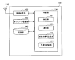
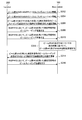
- FIG. 5 is a block diagram illustrating an example of a configuration of the base station 100 according to the present embodiment.
- the base station 100 includes an antenna unit 110, a wireless communication unit 120, a network communication unit 130, a storage unit 140, and a control unit 150.
- Antenna unit 110 The antenna unit 110 radiates a signal output by the wireless communication unit 120 into space as a radio wave.
- the antenna unit 110 converts a radio wave in space into a signal, and outputs the signal to the wireless communication unit 120.
- the antenna section 110 has a plurality of antenna elements and can form a beam.
- the wireless communication unit 120 transmits and receives signals. For example, the wireless communication unit 120 transmits a downlink signal to the terminal device and receives an uplink signal from the terminal device.
- the wireless communication unit 120 can form a plurality of beams by the antenna unit 110 and communicate with the terminal device.
- the network communication unit 130 transmits and receives information.
- the network communication unit 130 transmits information to another node and receives information from another node.
- the other nodes include other base stations and core network nodes.
- Storage unit 140 The storage unit 140 temporarily or permanently stores a program for the operation of the base station 100 and various data.
- Control unit 150 controls the overall operation of the base station 100 and provides various functions of the base station 100.
- the control unit 150 includes a setting unit 151, a notification unit 153, a measurement signal transmission unit 155, and a commonality evaluation unit 157.
- the setting unit 151 has a function of making settings related to communication with the terminal device 200. For example, the setting unit 151 performs resource configuration described later, and transmits resource configuration information indicating a resource configuration result to the terminal device 200.
- the notifier 153 has a function of notifying the terminal device 200 of commonality information described below.
- the notification unit 153 notifies information indicating the relationship between the beam directions of the downlink beam groups and / or setting information of the measurement report. Further, for example, the notifying unit 153 notifies information on linkage of beam sweeping using a plurality of beam groups. Further, for example, the notification unit 153 notifies an instruction for evaluating the commonality between the uplink beam groups and information specifying an uplink beam group to be subjected to beam sweeping.
- the measurement signal transmission unit 155 has a function of transmitting a measurement signal on the downlink. More specifically, the measurement signal transmitting unit 155 performs beam sweeping transmission of the measurement signal using a beam group defined for each of the plurality of frequency bandwidths.
- the commonality evaluation unit 157 has a function of evaluating commonality between uplink beam groups. More specifically, the commonality evaluation unit 157 measures a measurement signal beam-sweeped by the terminal device 200 using the beam group defined for each frequency bandwidth in each of the plurality of frequency bandwidths, and Assess commonality based on
- the control unit 150 may further include other components other than these components. That is, the control unit 150 can perform operations other than the operations of these components.
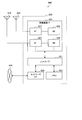
- FIG. 6 is a block diagram illustrating an example of a configuration of the terminal device 200 according to the present embodiment.
- the terminal device 200 includes an antenna unit 210, a wireless communication unit 220, a storage unit 230, and a control unit 240.
- Antenna unit 210 The antenna unit 210 radiates a signal output by the wireless communication unit 220 into space as a radio wave. Further, the antenna unit 210 converts a radio wave in space into a signal, and outputs the signal to the wireless communication unit 220.
- the antenna unit 210 has a plurality of antenna elements and can form a beam.
- Wireless communication unit 220 Wireless communication section 220 transmits and receives signals.
- the wireless communication unit 220 receives a downlink signal from a base station and transmits an uplink signal to the base station.
- the wireless communication unit 220 can form a plurality of beams using the antenna unit 210 and communicate with the base station.
- Storage unit 230 The storage unit 230 temporarily or permanently stores a program for operating the terminal device 200 and various data.
- Control unit 240 controls the overall operation of the terminal device 200 and provides various functions of the terminal device 200.
- the control unit 240 includes a measurement report unit 241 and a measurement signal transmission unit 243.
- the measurement report unit 241 has a function of measuring the measurement signal transmitted from the base station 100 and reporting the measurement result to the base station 100. More specifically, the measurement report unit 241 measures the measurement signal beam-sweeped by the base station 100 based on the commonality information notified from the base station 100, and reports the measurement result to the base station 100.
- the measurement signal transmitting unit 243 has a function of transmitting a measurement signal on the uplink. More specifically, the measurement signal transmitting unit 243 performs beam sweeping transmission of the measurement signal using a beam group defined for each of the plurality of frequency bandwidths.
- the control unit 240 may further include other components other than these components. That is, the control unit 240 can perform operations other than the operations of these components.
- First Embodiment the measurement result of the measurement signal transmitted by beam sweeping using the beam group defined in a certain frequency bandwidth is transmitted by beam sweeping transmission using the beam group defined in another frequency bandwidth. This is a form used as a measurement result of the measured signal for measurement.
- the technical problems of the present embodiment are as described above. Specifically, in an environment where a plurality of frequency bandwidths exist, it is burdensome for the terminal device to execute the beam selection procedure in the plurality of frequency bandwidths. This is because the more the number of times the beam selection procedure is executed, the more the amount of calculation increases, and accordingly the amount of power consumption increases. Further, radio resources for beam sweeping are prepared in all frequency bandwidths, so that radio resource overhead also increases.
- the base station 100 sets a beam group defined in each of the plurality of frequency bandwidths.
- the base station 100 performs resource configuration for a beam group defined in each of a plurality of frequency bandwidths.
- the resource configuration includes setting a radio resource (for example, a frequency resource and / or a time resource) used for beam sweeping transmission of the measurement signal using the beam group for each frequency bandwidth.
- the resource configuration may also include associating each of the plurality of beams belonging to the beam group with a measurement signal transmitted using the beam.
- the base station 100 (for example, the setting unit 151) transmits resource configuration information indicating a result of the resource configuration to the terminal device 200.
- the resource configuration information may include at least information indicating a radio resource used for beam sweeping transmission of the measurement signal using the beam group.
- the resource configuration information may include information for associating a frequency bandwidth with a beam group defined in the frequency bandwidth.
- the resource configuration information is, for each beam group, information that associates each of the plurality of beams belonging to the beam group, a measurement signal transmitted using the beam, and a radio resource used for transmitting the measurement signal. May be included.
- the base station 100 (for example, the notification unit 153) notifies the terminal device 200 of information on the commonality between the beam groups defined in different frequency bandwidths.
- the information on the commonality between the beam groups is hereinafter also referred to as commonality information.
- commonality information For notification of the commonality information, higher layer signaling (Higher layer signaling), system information, DCI (Downlink Control information), or dedicated signaling (dedicated signaling) may be used.
- the technical features of the present embodiment will be described using a first beam group defined corresponding to the first frequency bandwidth and a second beam group defined corresponding to the second frequency bandwidth. Is done.
- the first frequency bandwidth is also called BWP # 1
- the first beam group is also called beam group # 1
- the second frequency bandwidth is also called BWP # 2
- the second beam group is beam group Also called # 2.
- the measurement is performed on the beam group # 1 and at least a part of the measurement on the beam group # 2 is omitted.
- FIG. 7 is a diagram for explaining an outline of the commonality information according to the present embodiment.
- base station 100 can transmit beam group 40A as beam group # 1 defined in BWP # 1, and transmits beam group 40B as beam group # 2 defined in BWP # 2. It is possible.
- the beam directions of the beam group # 1 and the beam group # 2 may coincide. For example, as shown in FIG. 7, the direction of beam #i belonging to beam group # 1 and the direction of beam #j belonging to beam group # 2 match.
- the commonality information may include information indicating the relationship between the beam directions of the beam groups.
- the commonality information may include information indicating that the direction of the beam #i and the direction of the beam #j are common.
- the commonality information may include measurement report setting information.
- the commonality information includes information for setting one of the measurement results of the beam #i and the beam #j to be reported instead of the other measurement result.
- the terminal device 200 can use one measurement result of the beam #i and the beam #j instead of the other measurement result.
- the terminal device 200 can measure one of the beams #i and #j and omit the measurement of the other. Thereby, the load on the terminal device 200 is reduced.
- the commonality information includes information indicating the relationship between the beam directions of the beam groups and the case where the commonness information includes the setting information of the measurement report will be sequentially described in detail.
- the commonality information may include information indicating the relationship between the direction (that is, directivity) of the beam between the beam groups.
- the commonality information may include information indicating whether or not the beam direction characteristics are common between a plurality of beam groups defined in different frequency bandwidths.
- the commonality information may include information indicating that at least a part of the direction of the beam belonging to the beam group # 1 and the direction of the beam belonging to the beam group # 2 are common.
- the fact that the directions of a plurality of beams are common means that the directions of the plurality of beams are the same.
- the fact that the directions of the plurality of beams are common means that the analog circuit of the base station 100 has been calibrated so that the plurality of beams are transmitted in the same direction.
- the commonality information indicates that the direction (that is, the directivity) of the beam belonging to the beam group # 1 and the direction of the beam belonging to the beam group # 2 are all common. Includes information indicating that For example, the commonality information includes identification information of the beam group # 1 and identification information of the beam group # 2, and information indicating that the beam direction is common between the beam group # 1 and the beam group # 2.
- the identification information of the beam group includes the index of the beam group (for example, the beam group ID), the index of the beam belonging to the beam group (for example, the beam ID), and the measurement signal transmitted by beam sweeping using the beam group. Or information indicating a radio resource for beam sweeping transmission using a beam group.
- FIG. 8 is a diagram for explaining a specific example in a case where all the beams belonging to the beam group are common.
- base station 100 can transmit beam group 40A as beam group # 1, and can transmit beam group 40B as beam group # 2.
- Beam group # 1 and beam group # 2 include the following beams, respectively.
- the commonality information includes information indicating that the direction of the beam belonging to the beam group # 1 and the direction of the beam belonging to the beam group # 2 are common.
- the terminal device 200 (for example, the measurement report unit 241) measures the measurement signal beam-sweeping-transmitted using the beam group by the base station 100 based on the commonality information notified from the base station 100, and performs measurement. Report the results. Specifically, terminal apparatus 200 measures which beam group among a plurality of beam groups that can be used for beam sweeping transmission of a measurement signal by base station 100 based on the commonality information notified from base station 100. Select whether to target. Then, the terminal device 200 measures the beam group that is the measurement target, and does not measure the beam group that is not the measurement target. The terminal device 200 reports the measurement result of the beam group to be measured to the base station 100 instead of the measurement result of the beam group not to be measured.
- the terminal device 200 reports the measurement result of the beam group # 1 as the measurement result of the beam group # 2.
- the terminal device 200 compares the measurement result of the measurement signal transmitted by beam sweeping using the beam group # 1 with the measurement signal transmitted by beam sweeping using the beam group # 2. Is reported to the base station 100 instead of the measurement result.
- the terminal device 200 does not have to measure the measurement signal transmitted by beam sweeping using the beam group # 2. In that case, the terminal device 200 can omit the measurement for the beam group # 2, and the burden is reduced.
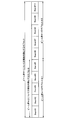
- FIG. 9 is a sequence diagram illustrating an example of a flow of a beam selection process performed by the system 1 according to the present embodiment.
- the base station 100 and the terminal device 200 are involved in this sequence.
- the base station 100 transmits resource configuration information for the beam group # 1 to the terminal device 200 (Step S102). Further, the base station 100 transmits the resource configuration for the beam group # 2 to the terminal device 200 (Step S104).
- the base station 100 transmits commonality information including information indicating that the direction of the beam belonging to the beam group # 1 and the direction of the beam belonging to the beam group # 2 are common to the terminal device 200 (step S106). ).
- the terminal device 200 determines to report the measurement results for the beam groups # 1 and # 2 based on the measurement results for the beam group # 1, based on the received commonality information (step S108). .
- base station 100 performs beam sweeping transmission of the measurement signal using beam group # 1 in BWP # 1 (step S110).
- terminal apparatus 200 performs measurement of the measurement signal transmitted by beam sweeping using beam group # 1 in BWP # 1, and reports the measurement result to base station 100 (step S112).
- base station 100 performs beam sweeping transmission of the measurement signal using beam group # 2 in BWP # 2 (step S114).
- terminal apparatus 200 reports the measurement result of the measurement signal transmitted by beam sweeping using beam group # 1 in BWP # 1 to base station 100 as the measurement result of beam group # 2 (step).
- S116 ).
- the base station 100 may omit transmission of the measurement signal using a beam common to beams belonging to other beam groups among beams belonging to the plurality of beam groups. Specifically, the base station 100 may omit the process in step S114. In this case, radio resources for beam sweeping transmission of the measurement signal in BWP # 2 can be released, and resource efficiency can be improved.
- the commonality information includes information indicating that a part of the direction of the beam belonging to the beam group # 1 and a part of the direction of the beam belonging to the beam group # 2 are common.
- the commonality information includes information indicating that the direction of the beam belonging to the subset of the beam group # 1 and the direction of the beam belonging to the beam group # 2 are common.
- the commonality information may include identification information of the beam group # 1 and identification information of the beam group # 2, and information indicating a subset of the beam group # 1 having the same beam direction as the beam group # 2.
- the beam direction may be common between the subset of the beam group # 1 and the subset of the beam group # 2.
- the commonality information includes information indicating that the beam direction is common between the subset of the beam group # 1 and the subset of the beam group # 2.
- the commonality information may include identification information of the beam group # 1 and identification information of the beam group # 2, and information indicating a subset of the beam group # 1 and a subset of the beam group # 2 having a common beam direction. .
- FIG. 10 is a diagram for explaining a specific example in a case where a subset of the beam group is common.
- base station 100 can transmit beam group 40A as beam group # 1, and can transmit beam group 40B as beam group # 2.
- the beam group # 1 and the beam group # 2 include the following beams, respectively.
- the commonality information includes information indicating that the direction of the beam belonging to the subset of the beam group # 1 and the direction of the beam belonging to the beam group # 2 are common.
- the terminal device 200 (for example, the measurement report unit 241), based on the commonality information notified from the base station 100, among a plurality of beam groups that can be used for beam sweeping transmission of the measurement signal by the base station 100 Select which beam group is to be measured. Further, terminal apparatus 200 specifies which subset of the beam group to be measured is to be reported instead of the measurement result of the beam group not to be measured. The terminal device 200 reports the measurement result of the specified subset of the beam group to be measured to the base station 100 instead of the measurement result of the beam group not to be measured.
- the terminal device 200 reports the measurement result of the subset of the beam group # 1 as the measurement result of the beam group # 2.
- the terminal device 200 transmits the measurement result of the measurement signal transmitted by beam sweeping using the beams # 1 to # 5 belonging to the beam group # 1 to the beam using the beam group # 2. It reports to base station 100 instead of the measurement result of the measurement signal transmitted by the sweep transmission.
- the received power of the beam # 8 is the highest in the beams # 1 to # 10
- the received power of the beam # 5 is the highest in the beams # 1 to # 5.
- terminal apparatus 200 reports that beam # 8 is optimal as a measurement result for beam group # 1, and reports that beam # 5 is optimal as a measurement result for beam group # 2.
- the terminal device 200 does not have to measure the measurement signal transmitted by beam sweeping using the beam group # 2. In that case, the terminal device 200 can omit the measurement for the beam group # 2, and the burden is reduced.
- the commonality information may include measurement report setting information.
- the commonality information may include information for setting to report the measurement result for the beam group # 2 based on the measurement result for the beam group # 1.
- the terminal device 200 can omit the measurement for the beam group # 2, and the burden is reduced.
- the commonality information is the beam group # 2 May include information for setting to report the measurement result for beam group # 1.
- the terminal device 200 (for example, the measurement report unit 241) reports a measurement result on the beam group # 1 based on the commonality information notified from the base station 100.
- Base station 100 handles the measurement result for beam group # 1 as the measurement result for beam group # 2.
- the terminal device 200 can omit the measurement for the beam group # 2, and the burden is reduced. Further, the terminal device 200 does not need to receive the setting for the beam group # 2 in the first place.
- the commonality information is the beam group # 1 And information indicating the range of the beam belonging to the beam group # 1 to be reported as the measurement result of each of the beam group # 2.
- the commonality information may include information indicating a range of a beam belonging to the beam group # 1 to be reported as a measurement result of the beam group # 2.
- the range of beams belonging to beam group # 1 may be considered as a subset of beam group # 1.
- the terminal device 200 (for example, the measurement report unit 241) reports the measurement result on the subset of the beam group # 1 based on the commonality information notified from the base station 100. For example, the terminal device 200 reports the measurement results for all beams belonging to the beam group # 1 as the measurement results for the beam group # 1. In addition, the terminal device 200 reports, as the measurement result of the beam group # 2, the measurement result of the beams belonging to the beam group # 1 and in the range specified by the commonality information. Thus, terminal apparatus 200 can omit measurement for beam group # 2, and the burden is reduced. Further, the terminal device 200 does not need to receive the setting for the beam group # 2 in the first place.
- this point will be specifically described with reference to FIG.
- FIG. 11 is a diagram for explaining an example of the commonality information according to the present embodiment.
- beam group # 1 for BWP # 1 includes beams # 1 to # 10.
- the report target range for the beam group # 1 is the beams # 1 to # 10.
- the report target range for beam group # 2 is beams # 1 to # 5.
- the commonality information includes measurement report setting information indicating that the range of the report target for the beam group # 1 is the beams # 1 to # 10.
- the base station 100 notifies the terminal device 200 of information for setting to report a beam having the maximum RSRP in the beams # 1 to # 10 of the beam group # 1 as a measurement result of the beam group # 1.
- the terminal device 200 reports information indicating the beam having the maximum RSRP among the beams # 1 to # 10 among the beam group # 1 to the base station 100 as the measurement result of the beam group # 1.
- the commonality information includes measurement report setting information indicating that the report target range for beam group # 2 is beams # 1 to # 5.
- the base station 100 notifies the terminal device 200 of information for setting to report a beam having the maximum RSRP in the beams # 1 to # 5 of the beam group # 1 as a measurement result of the beam group # 2. I do.
- the terminal device 200 reports information indicating the beam having the largest RSRP among the beams # 1 to # 5 in the beam group # 1 to the base station 100 as the measurement result of the beam group # 2.
- the base station 100 only needs to set the measurement report, and does not need to notify the information indicating the relationship of the beam direction between the beam groups.
- the commonality information indicates the measurement of each of the beam group # 1 and the beam group # 2. It may include information indicating a combination of subsets of beam group # 1 to be reported as a result.
- beam group # 1 is assumed to include a plurality of subsets.
- the commonality information includes information indicating a combination of target subsets to be reported as a measurement result for beam group # 1, that is, a combination including all subsets of beam group # 1.
- the commonality information includes information indicating a combination of target subsets to be reported as a measurement result of the beam group # 2, that is, information indicating a combination of a subset of the beam group # 1 having the same beam direction as the beam group # 2. .
- the terminal device 200 (for example, the measurement report unit 241) reports the measurement result on the subset of the beam group # 1 based on the commonality information notified from the base station 100. For example, the terminal device 200 reports the measurement result of the combination including all the subsets belonging to the beam group # 1 as the measurement result of the beam group # 1. Further, terminal apparatus 200 reports, as the measurement result of beam group # 2, the measurement result of the combination of the subset of beam group # 1 having the same beam direction as beam group # 2. Thus, terminal apparatus 200 can omit measurement for beam group # 2, and the burden is reduced. Further, the terminal device 200 does not need to receive the setting for the beam group # 2 in the first place.
- this point will be specifically described with reference to FIG.
- FIG. 12 is a diagram for explaining an example of the commonality information according to the present embodiment.
- beam group # 1 for BWP # 1 includes beams # 1 to # 10.
- the beam group # 1 for BWP # 1 includes a subset # 1 including beams # 1 to # 5 and a subset # 2 including beams # 6 to # 10.
- the report target for beam group # 1 is a combination of subsets # 1 and # 2.
- the report target for beam group # 2 is subset # 1.
- the commonality information includes measurement report setting information in which the report target for the beam group # 1 is a combination of the subsets # 1 and # 2.
- the base station 100 notifies the terminal device 200 of information for setting to report a beam having the maximum RSRP in the subsets # 1 and # 2 of the beam group # 1 as a measurement result of the beam group # 1.
- the terminal device 200 transmits information indicating the beam having the largest RSRP among the beams # 1 to # 10 belonging to the combination of the subsets # 1 and # 2 in the beam group # 1 as the measurement result for the beam group # 1. Report to station 100.
- the commonality information includes measurement report setting information that sets the report target for the beam group # 2 as the subset # 1.
- the base station 100 notifies the terminal device 200 of information for setting to report a beam having the maximum RSRP in the subset # 1 of the beam group # 1 as a measurement result of the beam group # 2.
- terminal apparatus 200 reports information indicating the beam having the largest RSRP among beams # 1 to # 5 belonging to subset # 1 of beam group # 1 to base station 100 as a measurement result for beam group # 2. .
- the commonality information transmitted in step S106 includes information for setting to report the measurement result for beam group # 2 based on the measurement result for beam group # 1.
- Second Embodiment is performed over a plurality of frequency bandwidths while switching the frequency bandwidth to be used.
- the number of simultaneously usable frequency bandwidths may be limited due to the capability of the terminal device 200.
- the number of frequency bandwidths that can be used simultaneously by the terminal device 200 may be one.
- the terminal device 200 can transmit and receive signals in a plurality of frequency bandwidths by switching the frequency bandwidth to be used.
- the beam selection procedure can be performed while switching the used frequency bandwidth. This will be described with reference to FIG.
- FIG. 13 is a diagram for explaining the technical problem of the present embodiment. As shown in FIG. 13, beam sweeping is performed in a time zone in which BWP # 3 is active, and then beam sweeping is performed in a time zone in which BWP # 4 is active. However, if the active BWP is switched frequently, it may be difficult to complete beam sweeping within the time when one BWP is active.
- the beam sweeping method shown in FIG. 13 is realized by 3GPP @ Rel15.
- the base station 100 (for example, the measurement signal transmitting unit 155) according to the present embodiment uses a beam sweep using a beam group defined in a certain frequency bandwidth. Part of the ping is represented by beam sweeping using beams defined in other frequency bandwidths. Thereby, even when it is difficult to complete beam sweeping within the time when one BWP is active, it is possible to perform beam sweeping over a plurality of BWPs while switching BWPs. .
- the third frequency bandwidth is also called BWP # 3
- the third beam group is also called beam group # 3
- the fourth frequency bandwidth is also called BWP # 4
- the fourth beam group is beam group Also called # 4. It is assumed that at least a part of the beam direction is common to the beam group # 3 and the beam group # 4. In this case, of the beam sweeping using the beam group # 3, the beam sweeping using the beam common to the beam group # 4 is represented by the beam sweeping using the beam group # 4.
- the base station 100 (for example, the measurement signal transmitting unit 155) transmits a subset of the beam group # 3 and a beam group # 4 or a subset thereof having the same beam direction as the other subset of the beam group # 3. Correspond. Such association is also called linkage. Then, the base station 100 performs beam sweeping transmission of the measurement signal using the subset of the linked beam group # 3 and the beam group # 4 or the subset thereof.
- the base station 100 (for example, the notification unit 153) notifies the terminal device 200 of the information on the linkage as the commonality information.
- the commonality information reports the measurement result of the subset of the beam group # 3 and the measurement result of the beam belonging to the beam group # 4 having the same beam direction as the other subset of the beam group # 3 in association with each other.
- the commonality information includes at least information indicating a subset of the beam group # 3 and a beam group # 4 or a subset thereof to be linked.
- the terminal device 200 (for example, the measurement report unit 241) measures the measurement result for the subset of the beam group # 3 and the beam belonging to the beam group # 4 having the same direction as the beam belonging to another subset of the beam group # 3. The measurement results are reported in association with each other. More specifically, terminal apparatus 200 transmits a measurement signal transmitted using a subset of beam group # 3 and a beam belonging to beam group # 4 having the same direction as a beam belonging to another subset of beam group # 3. The measurement result of the measurement signal transmitted using the measurement result is reported as the measurement result of beam group # 3.
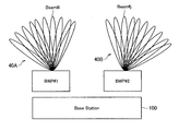
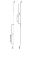
- FIG. 14 is a diagram illustrating an example of a linkage of beam sweeping using a plurality of beam groups according to the present embodiment.
- the base station 100 can use BWP # 3 and BWP # 4, and it is assumed that the terminal device 200 can simultaneously use one BWP. Further, it is assumed that base station 100 can transmit beam group # 3 defined by BWP # 3 and can transmit beam group # 4 defined by BWP # 4. Further, the beam group # 3 and the beam group # 4 include the following beams, respectively.
- Beam group # 4 Beam # 1, beam # 2, ..., beam # 10
- beams having the same index have the same directivity.
- the base station 100 links the subset of the beam group # 3 with the subset of the beam group # 4 having the same beam direction as the other subset of the beam group # 3. For example, base station 100 links beams # 1 to # 5 belonging to beam group # 3 and beams # 6 to # 10 belonging to beam group # 4.
- the base station 100 notifies the terminal device 200 of information for setting to report the measurement result of each linked subset in association with each other. Then, as shown in FIG. 14, the base station 100 performs beam sweeping transmission of the measurement signal using each of the linked subsets while switching from BWP # 3 to # 4.
- the base station 100 performs beam sweeping transmission of the measurement signal using the beams # 1 to # 5 belonging to the beam group # 3 during a time period when BWP # 3 is active.
- base station 100 performs beam sweeping transmission of the measurement signal using beams # 6 to # 10 belonging to beam group # 4 during a time period when BWP # 4 is active.
- Terminal apparatus 200 transmits measurement signals transmitted using beams # 1 to # 5 belonging to beam group # 3 and measurement signals transmitted using beams # 6 to # 10 belonging to beam group # 4. ,Measure. Then, terminal apparatus 200 reports these measurement results to base station 100 as measurement results for beam group # 3. For example, the terminal device 200 reports, to the base station 100, the values of the beam ID and the RSRP of one of the beams having the highest RSRP or the upper K beams having the highest RSRP.
- the terminal device 200 reports the highest one beam, it can be said that beam selection is executed by the terminal device 200.
- the terminal device 200 reports K beams with a high RSRP, the base station 100 selects a beam from the K beams.
- a part of the beam sweeping using the beam group # 3 is represented by the beam sweeping using the beam group # 4. Therefore, even when it is difficult to complete the beam sweeping within the time when one BWP is active, it is possible to perform the beam sweeping seamlessly while switching the BWP.
- FIG. 15 is a sequence diagram illustrating an example of a flow of a beam selection process performed by the system 1 according to the present embodiment.
- the base station 100 and the terminal device 200 are involved in this sequence.
- the base station 100 transmits resource configuration information for the beam group # 3 to the terminal device 200 (Step S202). Further, the base station 100 transmits the resource configuration for the beam group # 4 to the terminal device 200 (Step S204).
- the base station 100 transmits first commonality information including information indicating the relationship between the beam directions of the beam groups # 3 and # 4 to the terminal device 200 (Step S206).
- the first commonality information includes information indicating that the direction of the beam belonging to beam group # 3 and the direction of the beam belonging to beam group # 4 are common.
- the base station 100 transmits, to the terminal device 200, the second common information including information on the linkage of beam sweeping using the beam groups # 3 and # 4 (Step S208).
- the second commonality information includes a measurement result for the subset of the beam group # 3 and a measurement result for the beam belonging to the beam group # 4 having the same beam direction as the other subset of the beam group # 3. , And information to be set to be reported in association with each other.
- the base station 100 performs beam sweeping transmission of the measurement signal using the subset of the beam group # 3 during the time period when BWP # 3 is active (step S210).
- base station 100 performs beam sweeping transmission of the measurement signal using the subset of beam group # 4 having the same beam direction as the other subset of beam group # 3 during the time period when BWP # 4 is active. (S212).
- terminal apparatus 200 reports the measurement result of the measurement signal transmitted by beam sweeping in BWP # 3 and BWP # 4 to base station 100 as the measurement result of beam group # 3 (step S214).
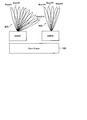
- FIG. 16 is a diagram for explaining another example of the linkage of beam sweeping using a plurality of beam groups according to the present embodiment.
- the base station 100 can use BWP # 3 and BWP # 4, and the terminal device 200 can use two BWPs at the same time. Further, it is assumed that base station 100 can transmit beam group # 3 defined by BWP # 3 and can transmit beam group # 4 defined by BWP # 4. Further, the beam group # 3 and the beam group # 4 include the following beams, respectively.
- Beam group # 4 Beam # 1, beam # 2, ..., beam # 10
- beams having the same index have the same directivity.
- the base station 100 simultaneously performs beam sweeping transmission of the measurement signal using the linked subset of the beam group # 3 and the subset of the beam group # 4. That is, the base station 100 may simultaneously perform beam sweeping using a linked beam group in a plurality of BWPs.
- the base station 100 evaluates the commonality of a plurality of uplink beam groups, and the terminal device 200 omits the beam sweeping using one of the plurality of beam groups evaluated to be common. .
- the load on the terminal device 200 in the case where the measurement signal is beam-sweep-transmitted on the downlink and the downlink Tx beam is selected has been reduced.
- the load on the terminal device 200 in the case where the measurement signal is beam-sweep-transmitted on the uplink and a Tx beam for the uplink is selected is reduced.
- the base station 100 can determine whether or not the beam directions of a plurality of uplink beam groups defined in different frequency bandwidths are common, but it is difficult for the terminal device 200 to determine. is there.
- the base station 100 (for example, the setting unit 151) sets a beam group defined in each of a plurality of frequency bandwidths.
- the beam group is an uplink Tx beam.
- the base station 100 performs resource configuration for a beam group including a plurality of uplink Tx beams defined in each of a plurality of frequency bandwidths.
- the terminal device 200 can transmit a beam group # 5 (corresponding to a fifth beam group) defined in BWP # 5 (corresponding to a fifth frequency bandwidth).
- terminal apparatus 200 can transmit beam group # 6 (corresponding to the sixth beam group) defined in BWP # 6 (corresponding to the sixth frequency bandwidth).
- the beam group # 5 and the beam group # 6 include the following beams, respectively. Beam group # 5: Beam # 1, beam # 2, ..., beam # 10
- Beam group # 6 Beam # 1, beam # 2, ..., beam # 10
- beams having the same index have the same directivity.
- the base station 100 (for example, the notification unit 153) includes information that instructs to perform beam sweeping transmission of a measurement signal using a plurality of uplink beams defined in each of a plurality of frequency bandwidths.
- the sex information is notified to the terminal device 200.
- the base station 100 notifies the terminal device 200 of information instructing to perform beam sweeping transmission of the measurement signal using the beam group # 5 and the beam group # 6.
- the base station 100 instructs the terminal device 200 to perform beam sweeping transmission of the measurement signal using the beam group # 5, and then performs beam sweeping of the measurement signal using the beam group # 6. Instruct ping transmission.
- the terminal device 200 (for example, the measurement signal transmission unit 243) transmits a measurement signal using a plurality of uplink beam groups defined in each of a plurality of frequency bandwidths based on the notification from the base station 100. Perform beam sweeping transmission. For example, the terminal device 200 performs beam sweeping transmission of the measurement signal using the beam group # 5 and the beam group # 6.
- the base station 100 (for example, the commonality evaluation unit 157) measures the measurement signal beam-sweeping-transmitted by the terminal device 200 using the plurality of uplink beams, and outputs the plurality of uplink beams. Assess the commonality of Specifically, the base station 100 determines whether the direction of the beam belonging to the beam group # 5 and the direction of the beam belonging to the beam group # 6 match based on the measurement result, and further specifies the matching beam. I do. For example, regarding the above specific example, the base station 100 determines that the directions of the beams belonging to the beam group # 5 and the directions of the beams belonging to the beam group # 6 all match.
- the base station 100 (for example, the notification unit 153) notifies information specifying an uplink beam group to be subjected to beam sweeping based on the evaluation result.
- the base station 100 for example, the notification unit 153
- the commonality information includes information instructing not to perform beam sweeping transmission of a measurement signal using an uplink beam group defined in a specific frequency bandwidth.
- An uplink beam group defined in a specific frequency bandwidth here is a beam group whose beam direction coincides with another beam group, or whose beam direction coincides with a subset of another beam group. is there.
- the commonality information may include information instructing not to perform beam sweeping transmission of the measurement signal using the beam group # 6.
- the commonality information may be information that instructs to delete the resource configuration related to the beam group # 6.
- the commonality information includes information instructing to perform beam sweeping transmission of a measurement signal using an uplink beam group defined in a specific frequency bandwidth.
- the uplink beam group defined in a specific frequency bandwidth means that the beam direction coincides with another beam group, or a subset of the beam group coincides with the beam direction of another beam group.
- a beam group A beam group.
- the commonality information may include information instructing to perform beam sweeping transmission of the measurement signal using the beam group # 5.
- the terminal device 200 (for example, the measurement signal transmitting unit 243) performs the measurement using some of the uplink beam groups among the uplink beam groups defined in each of the plurality of frequency bandwidths. Beam sweeping transmission of a measurement signal using another uplink beam group is performed without performing beam sweeping transmission of the signal.
- the terminal device 200 does not perform beam sweeping transmission of the measurement signal using the beam group # 6, but performs beam sweeping transmission of the measurement signal using the beam group # 5. Since the beam directions of beam group # 5 and beam group # 6 are common, base station 100 can handle the measurement result of beam group # 5 as the measurement result of beam group # 6. . That is, the base station 100 can omit the measurement for the beam group # 6. In addition, the terminal device 200 can omit the beam sweeping transmission of the measurement signal using the beam group # 6. Therefore, the burden on both the base station 100 and the terminal device 200 is reduced.
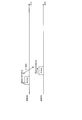
- FIG. 17 is a sequence diagram illustrating an example of a flow of a beam selection process performed by the system 1 according to the present embodiment.
- the base station 100 and the terminal device 200 are involved in this sequence.
- the base station 100 transmits resource configuration information for beam group # 5 to the terminal device 200 (Step S302).
- the base station 100 transmits the resource configuration for the beam group # 6 to the terminal device 200 (Step S304).
- the base station 100 transmits commonality information including information instructing to perform beam sweeping transmission of the measurement signal using each of the beam groups # 5 and # 6 to the terminal device 200 (Step S306).
- terminal apparatus 200 performs beam sweeping transmission of the measurement signal using beam group # 5 in BWP # 5 (step S308). Further, terminal device 200 performs beam sweeping transmission of the measurement signal using beam group # 6 in BWP # 6 (step S310).
- base station 100 measures the measurement signal transmitted by beam sweeping using each of beam groups # 5 and # 6, and evaluates the commonality of beam groups # 5 and # 6 based on the measurement result. (Step S312). Here, it is assumed that the beam groups # 5 and # 6 are determined to have the same beam direction.
- the base station 100 transmits commonality information including information instructing not to perform beam sweeping transmission of the measurement signal using the beam group # 6 to the terminal device 200 (step S314).
- the commonality information here may be information that instructs to delete the resource configuration related to the beam group # 6.
- the commonality information here may include information instructing to perform beam sweeping transmission of the measurement signal using the beam group # 5.
- terminal apparatus 200 performs beam sweeping transmission of the measurement signal using beam group # 5 in BWP # 5 (step S316).
- the base station 100 may be realized as any type of eNB (evolved ⁇ Node ⁇ B) such as a macro eNB or a small eNB.
- the small eNB may be an eNB that covers a cell smaller than a macro cell, such as a pico eNB, a micro eNB, or a home (femto) eNB.
- the base station 100 may be realized as another type of base station such as NodeB or BTS (Base @ Transceiver @ Station).
- the base station 100 may include a main unit (also referred to as a base station device) that controls wireless communication, and one or more RRHs (Remote / Radio / Head) arranged at a different location from the main unit. Further, various types of terminals described later may operate as the base station 100 by temporarily or semi-permanently executing the base station function.
- the terminal device 200 is a mobile terminal such as a smartphone, a tablet PC (Personal Computer), a notebook PC, a portable game terminal, a portable / dongle type mobile router or a digital camera, or a vehicle-mounted terminal such as a car navigation device. It may be realized as. Further, the terminal device 200 may be realized as a terminal that performs M2M (Machine @ To @ Machine) communication (also referred to as an MTC (Machine @ Type @ Communication) terminal). Furthermore, the terminal device 200 may be a wireless communication module (for example, an integrated circuit module configured with one die) mounted on these terminals.
- M2M Machine @ To @ Machine
- MTC Machine @ Type @ Communication
- FIG. 18 is a block diagram illustrating a first example of a schematic configuration of an eNB to which the technology according to the present disclosure can be applied.
- the eNB 800 includes one or more antennas 810 and a base station device 820. Each antenna 810 and the base station device 820 can be connected to each other via an RF cable.
- Each of the antennas 810 has a single or a plurality of antenna elements (for example, a plurality of antenna elements constituting a MIMO antenna), and is used for transmission and reception of radio signals by the base station apparatus 820.
- the eNB 800 includes a plurality of antennas 810 as illustrated in FIG. 18, and the plurality of antennas 810 may correspond to, for example, a plurality of frequency bands used by the eNB 800, respectively.
- FIG. 18 illustrates an example in which the eNB 800 includes a plurality of antennas 810, the eNB 800 may include a single antenna 810.
- the base station device 820 includes a controller 821, a memory 822, a network interface 823, and a wireless communication interface 825.
- the controller 821 may be, for example, a CPU or a DSP, and operates various functions of an upper layer of the base station device 820. For example, the controller 821 generates a data packet from the data in the signal processed by the wireless communication interface 825, and transfers the generated packet via the network interface 823. The controller 821 may generate a bundled packet by bundling data from a plurality of baseband processors, and transfer the generated bundled packet. Also, the controller 821 executes logic such as radio resource management (Radio Resource Control), radio bearer control (Radio Bear Control), mobility management (Mobility Management), inflow control (Admission Control), or scheduling (Scheduling). Function may be provided.
- Radio Resource Control Radio Resource Control
- Radio Bear Control radio bearer control
- Mobility Management Mobility Management
- Admission Control Inflow control
- scheduling scheduling
- the control may be executed in cooperation with a peripheral eNB or a core network node.
- the memory 822 includes a RAM and a ROM, and stores a program executed by the controller 821 and various control data (for example, a terminal list, transmission power data, scheduling data, and the like).
- the network interface 823 is a communication interface for connecting the base station device 820 to the core network 824.
- the controller 821 may communicate with a core network node or another eNB via the network interface 823.
- the eNB 800 and the core network node or another eNB may be connected to each other by a logical interface (for example, an S1 interface or an X2 interface).
- Network interface 823 may be a wired communication interface or a wireless communication interface for wireless backhaul.
- the network interface 823 may use a higher frequency band for wireless communication than the frequency band used by the wireless communication interface 825.
- the wireless communication interface 825 supports any of the cellular communication methods such as LTE (Long Term Evolution) or LTE-Advanced, and provides wireless connection to a terminal located in the cell of the eNB 800 via the antenna 810.
- the wireless communication interface 825 may typically include a baseband (BB) processor 826, an RF circuit 827, and the like.
- the BB processor 826 may perform, for example, encoding / decoding, modulation / demodulation, multiplexing / demultiplexing, and the like.
- Each layer eg, L1, MAC (Medium Access Control), RLC (Radio Link Control), and PDCP) (Packet ⁇ Data ⁇ Convergence ⁇ Protocol)).
- the BB processor 826 may have some or all of the above-described logical functions instead of the controller 821.
- the BB processor 826 may be a module that includes a memory that stores a communication control program, a processor that executes the program, and a related circuit. The function of the BB processor 826 may be changed by updating the program. Good.
- the module may be a card or a blade inserted into a slot of the base station device 820, or may be a chip mounted on the card or the blade.
- the RF circuit 827 may include a mixer, a filter, an amplifier, and the like, and transmits and receives wireless signals via the antenna 810.
- the wireless communication interface 825 includes a plurality of BB processors 826 as shown in FIG. 18, and the plurality of BB processors 826 may correspond to, for example, a plurality of frequency bands used by the eNB 800, respectively.
- the wireless communication interface 825 includes a plurality of RF circuits 827 as shown in FIG. 18, and the plurality of RF circuits 827 may correspond to, for example, a plurality of antenna elements, respectively.
- FIG. 18 illustrates an example in which the wireless communication interface 825 includes a plurality of BB processors 826 and a plurality of RF circuits 827.
- the wireless communication interface 825 includes a single BB processor 826 or a single RF circuit 827. May be.
- one or more components included in the control unit 150 described with reference to FIG. 5 may be implemented in the wireless communication interface 825.
- the eNB 800 includes a module including a part (for example, the BB processor 826) or all of the wireless communication interface 825 and / or the controller 821, and the one or more components described above may be mounted on the module. Good.
- the module stores a program for causing a processor to function as the one or more components (in other words, a program for causing the processor to execute the operations of the one or more components).
- the program may be executed.
- a program for causing the processor to function as the one or more components is installed in the eNB 800, and the wireless communication interface 825 (for example, the BB processor 826) and / or the controller 821 executes the program.
- the eNB 800, the base station device 820, or the module may be provided as a device including the one or more components, and a program for causing a processor to function as the one or more components is provided. You may. Further, a readable recording medium on which the program is recorded may be provided.
- the wireless communication unit 120 described with reference to FIG. 5 may be implemented in the wireless communication interface 825 (for example, the RF circuit 827). Further, the antenna unit 110 may be mounted on the antenna 810. Further, the network communication unit 130 may be implemented in the controller 821 and / or the network interface 823. Further, the storage unit 140 may be implemented in the memory 822.
- FIG. 19 is a block diagram illustrating a second example of a schematic configuration of an eNB to which the technology according to the present disclosure can be applied.
- the eNB 830 includes one or more antennas 840, a base station device 850, and an RRH 860. Each antenna 840 and RRH 860 may be connected to each other via an RF cable. Further, the base station device 850 and the RRH 860 can be connected to each other by a high-speed line such as an optical fiber cable.
- Each of the antennas 840 has a single or a plurality of antenna elements (for example, a plurality of antenna elements constituting a MIMO antenna), and is used for transmission and reception of a radio signal by the RRH 860.
- the eNB 830 includes a plurality of antennas 840 as illustrated in FIG. 19, and the plurality of antennas 840 may correspond to, for example, a plurality of frequency bands used by the eNB 830, respectively.
- FIG. 19 illustrates an example in which the eNB 830 has a plurality of antennas 840, the eNB 830 may have a single antenna 840.
- the base station device 850 includes a controller 851, a memory 852, a network interface 853, a wireless communication interface 855, and a connection interface 857.
- the controller 851, the memory 852, and the network interface 853 are the same as the controller 821, the memory 822, and the network interface 823 described with reference to FIG.
- the wireless communication interface 855 supports any cellular communication scheme such as LTE or LTE-Advanced, and provides a wireless connection to a terminal located in a sector corresponding to the RRH 860 via the RRH 860 and the antenna 840.
- the wireless communication interface 855 may typically include a BB processor 856 and the like.
- the BB processor 856 is similar to the BB processor 826 described with reference to FIG. 18 except that the BB processor 856 is connected to the RF circuit 864 of the RRH 860 via the connection interface 857.
- the wireless communication interface 855 includes a plurality of BB processors 856 as illustrated in FIG.
- the plurality of BB processors 856 may correspond to, for example, a plurality of frequency bands used by the eNB 830, respectively.
- FIG. 19 illustrates an example in which the wireless communication interface 855 includes a plurality of BB processors 856, the wireless communication interface 855 may include a single BB processor 856.
- connection interface 857 is an interface for connecting the base station device 850 (wireless communication interface 855) to the RRH 860.
- the connection interface 857 may be a communication module for communication on the high-speed line that connects the base station device 850 (wireless communication interface 855) and the RRH 860.
- the RRH 860 includes a connection interface 861 and a wireless communication interface 863.
- connection interface 861 is an interface for connecting the RRH 860 (wireless communication interface 863) to the base station device 850.
- the connection interface 861 may be a communication module for communication on the high-speed line.
- the wireless communication interface 863 sends and receives wireless signals via the antenna 840.
- the wireless communication interface 863 may typically include an RF circuit 864 and the like.
- the RF circuit 864 may include a mixer, a filter, an amplifier, and the like, and transmits and receives wireless signals via the antenna 840.
- the wireless communication interface 863 includes a plurality of RF circuits 864 as shown in FIG. 19, and the plurality of RF circuits 864 may correspond to, for example, a plurality of antenna elements, respectively.
- FIG. 19 illustrates an example in which the wireless communication interface 863 includes a plurality of RF circuits 864, the wireless communication interface 863 may include a single RF circuit 864.
- one or more components may be implemented in the wireless communication interface 855 and / or the wireless communication interface 863.
- the controller 851 may include a module including a part (for example, the BB processor 856) or all of the wireless communication interface 855 and / or the controller 851, and the one or more components may be mounted on the module. Good.
- the module stores a program for causing a processor to function as the one or more components (in other words, a program for causing the processor to execute the operations of the one or more components).
- the program may be executed.
- a program for causing the processor to function as the one or more components is installed in the eNB 830, and the wireless communication interface 855 (for example, the BB processor 856) and / or the controller 851 executes the program.
- the eNB 830, the base station device 850, or the module may be provided as a device including the one or more components, and a program for causing a processor to function as the one or more components is provided. You may. Further, a readable recording medium on which the program is recorded may be provided.
- the wireless communication unit 120 described with reference to FIG. 5 may be implemented in the wireless communication interface 863 (for example, the RF circuit 864). Further, the antenna unit 110 may be mounted on the antenna 840. Further, the network communication unit 130 may be implemented in the controller 851 and / or the network interface 853. Further, the storage unit 140 may be implemented in the memory 852.
- FIG. 20 is a block diagram illustrating an example of a schematic configuration of a smartphone 900 to which the technology according to the present disclosure may be applied.
- the smartphone 900 includes a processor 901, a memory 902, a storage 903, an external connection interface 904, a camera 906, a sensor 907, a microphone 908, an input device 909, a display device 910, a speaker 911, a wireless communication interface 912, and one or more antenna switches 915. And one or more antennas 916, a bus 917, a battery 918, and an auxiliary controller 919.
- the processor 901 may be, for example, a CPU or an SoC (System on Chip), and controls functions of an application layer and other layers of the smartphone 900.
- the memory 902 includes a RAM and a ROM, and stores programs and data executed by the processor 901.
- the storage 903 may include a storage medium such as a semiconductor memory or a hard disk.
- the external connection interface 904 is an interface for connecting an external device such as a memory card or a USB (Universal Serial Bus) device to the smartphone 900.
- the camera 906 has an image sensor such as a CCD (Charge Coupled Device) or a CMOS (Complementary Metal Oxide Semiconductor), and generates a captured image.
- the sensor 907 may include, for example, a sensor group such as a positioning sensor, a gyro sensor, a geomagnetic sensor, and an acceleration sensor.
- Microphone 908 converts audio input to smartphone 900 into an audio signal.
- the input device 909 includes, for example, a touch sensor that detects a touch on the screen of the display device 910, a keypad, a keyboard, a button or a switch, and receives an operation or information input from a user.
- the display device 910 has a screen such as a liquid crystal display (LCD) or an organic light emitting diode (OLED) display, and displays an output image of the smartphone 900.
- Speaker 911 converts an audio signal output from smartphone 900 into audio.
- the wireless communication interface 912 supports any one of cellular communication systems such as LTE and LTE-Advanced, and executes wireless communication.
- the wireless communication interface 912 may typically include a BB processor 913, an RF circuit 914, and the like.
- the BB processor 913 may perform, for example, encoding / decoding, modulation / demodulation, multiplexing / demultiplexing, and perform various signal processing for wireless communication.
- the RF circuit 914 may include a mixer, a filter, an amplifier, and the like, and transmits and receives wireless signals via the antenna 916.
- the wireless communication interface 912 may be a one-chip module in which the BB processor 913 and the RF circuit 914 are integrated.
- the wireless communication interface 912 may include a plurality of BB processors 913 and a plurality of RF circuits 914 as illustrated in FIG. Although FIG. 20 illustrates an example in which the wireless communication interface 912 includes a plurality of BB processors 913 and a plurality of RF circuits 914, the wireless communication interface 912 includes a single BB processor 913 or a single RF circuit 914. May be.
- the wireless communication interface 912 may support other types of wireless communication methods such as a short-range wireless communication method, a close-range wireless communication method, or a wireless LAN (Local Area Network) method, in addition to the cellular communication method, In that case, a BB processor 913 and an RF circuit 914 for each wireless communication scheme may be included.
- Each of the antenna switches 915 switches the connection destination of the antenna 916 among a plurality of circuits (for example, circuits for different wireless communication systems) included in the wireless communication interface 912.
- Each of the antennas 916 has a single or a plurality of antenna elements (for example, a plurality of antenna elements constituting a MIMO antenna), and is used for transmission and reception of a radio signal by the radio communication interface 912.
- the smartphone 900 may include a plurality of antennas 916 as illustrated in FIG. Note that FIG. 20 illustrates an example in which the smartphone 900 includes a plurality of antennas 916; however, the smartphone 900 may include a single antenna 916.
- the smartphone 900 may include an antenna 916 for each wireless communication system.
- the antenna switch 915 may be omitted from the configuration of the smartphone 900.
- the bus 917 connects the processor 901, the memory 902, the storage 903, the external connection interface 904, the camera 906, the sensor 907, the microphone 908, the input device 909, the display device 910, the speaker 911, the wireless communication interface 912, and the auxiliary controller 919 to each other.
- the battery 918 supplies power to each block of the smartphone 900 illustrated in FIG. 20 via a power supply line partially indicated by a broken line in the drawing.
- the auxiliary controller 919 operates the minimum functions of the smartphone 900, for example, in the sleep mode.
- the smartphone 900 illustrated in FIG. 20 one or more components (the measurement report unit 241 and / or the measurement signal transmission unit 243) included in the control unit 240 described with reference to FIG. May be implemented. Alternatively, at least some of these components may be implemented in processor 901 or auxiliary controller 919.
- the smartphone 900 includes a module including a part (for example, the BB processor 913) or all of the wireless communication interface 912, the processor 901, and / or the auxiliary controller 919, and the one or more components in the module. May be implemented.
- the module stores a program for causing a processor to function as the one or more components (in other words, a program for causing the processor to execute the operations of the one or more components). The program may be executed.
- a program for causing a processor to function as the one or more components is installed in the smartphone 900, and the wireless communication interface 912 (for example, the BB processor 913), the processor 901, and / or the auxiliary controller 919 is installed in the smartphone 900.
- the program may be executed.
- the smartphone 900 or the module may be provided as a device including the one or more components, and a program for causing a processor to function as the one or more components may be provided. Further, a readable recording medium on which the program is recorded may be provided.
- the wireless communication unit 220 described with reference to FIG. 6 may be implemented in the wireless communication interface 912 (for example, the RF circuit 914). Further, the antenna unit 210 may be mounted on the antenna 916. Further, the storage unit 230 may be implemented in the memory 902.
- FIG. 21 is a block diagram illustrating an example of a schematic configuration of a car navigation device 920 to which the technology according to the present disclosure may be applied.
- the car navigation device 920 includes a processor 921, a memory 922, a GPS (Global Positioning System) module 924, a sensor 925, a data interface 926, a content player 927, a storage medium interface 928, an input device 929, a display device 930, a speaker 931, and wireless communication.
- An interface 933, one or more antenna switches 936, one or more antennas 937, and a battery 938 are provided.
- the processor 921 may be, for example, a CPU or an SoC, and controls the navigation function and other functions of the car navigation device 920.
- the memory 922 includes a RAM and a ROM, and stores programs executed by the processor 921 and data.
- the GPS module 924 measures the position (for example, latitude, longitude, and altitude) of the car navigation device 920 using a GPS signal received from a GPS satellite.
- the sensor 925 may include, for example, a sensor group such as a gyro sensor, a geomagnetic sensor, and a barometric pressure sensor.
- the data interface 926 is connected to the in-vehicle network 941 via a terminal (not shown), for example, and acquires data generated on the vehicle side such as vehicle speed data.
- the content player 927 reproduces the content stored on the storage medium (for example, CD or DVD) inserted into the storage medium interface 928.
- the input device 929 includes, for example, a touch sensor, a button, or a switch that detects a touch on the screen of the display device 930, and receives an operation or information input from a user.
- the display device 930 has a screen such as an LCD or an OLED display, and displays an image of a navigation function or content to be reproduced.
- the speaker 931 outputs the navigation function or the sound of the content to be reproduced.
- the wireless communication interface 933 supports any of the cellular communication systems such as LTE and LTE-Advanced, and executes wireless communication.
- the wireless communication interface 933 may typically include a BB processor 934, an RF circuit 935, and the like.
- the BB processor 934 may perform, for example, encoding / decoding, modulation / demodulation, and multiplexing / demultiplexing, and performs various signal processings for wireless communication.
- the RF circuit 935 may include a mixer, a filter, an amplifier, and the like, and transmits and receives wireless signals via the antenna 937.
- the wireless communication interface 933 may be a one-chip module in which the BB processor 934 and the RF circuit 935 are integrated.
- the wireless communication interface 933 may include a plurality of BB processors 934 and a plurality of RF circuits 935 as illustrated in FIG. Note that FIG. 21 illustrates an example in which the wireless communication interface 933 includes a plurality of BB processors 934 and a plurality of RF circuits 935. However, the wireless communication interface 933 includes a single BB processor 934 or a single RF circuit 935. May be.
- the wireless communication interface 933 may support other types of wireless communication methods such as a short-range wireless communication method, a close-range wireless communication method, or a wireless LAN method in addition to the cellular communication method.
- a BB processor 934 and an RF circuit 935 for each communication method may be included.
- Each of the antenna switches 936 switches the connection destination of the antenna 937 among a plurality of circuits (for example, circuits for different wireless communication systems) included in the wireless communication interface 933.
- Each of the antennas 937 has a single or a plurality of antenna elements (for example, a plurality of antenna elements constituting a MIMO antenna), and is used for transmission and reception of a radio signal by the radio communication interface 933.
- the car navigation device 920 may include a plurality of antennas 937 as shown in FIG. Although FIG. 21 illustrates an example in which the car navigation device 920 includes a plurality of antennas 937, the car navigation device 920 may include a single antenna 937.
- the car navigation device 920 may include an antenna 937 for each wireless communication system.
- the antenna switch 936 may be omitted from the configuration of the car navigation device 920.
- the battery 938 supplies power to each block of the car navigation device 920 shown in FIG. 21 via a power supply line partially indicated by a broken line in the drawing.
- the battery 938 stores power supplied from the vehicle.
- the car navigation device 920 includes a module including a part (for example, the BB processor 934) or all and / or the processor 921 of the wireless communication interface 933, and the one or more components are mounted in the module. You may.
- the module stores a program for causing a processor to function as the one or more components (in other words, a program for causing the processor to execute the operations of the one or more components). The program may be executed.
- a program for causing a processor to function as the one or more components is installed in the car navigation device 920, and the wireless communication interface 933 (for example, the BB processor 934) and / or the processor 921 executes the program.
- the car navigation device 920 or the module may be provided as a device including the one or more components, and a program for causing a processor to function as the one or more components may be provided. Good. Further, a readable recording medium on which the program is recorded may be provided.
- the wireless communication unit 220 described with reference to FIG. 6 may be implemented in the wireless communication interface 933 (for example, the RF circuit 935). Further, the antenna unit 210 may be mounted on the antenna 937. Further, the storage unit 230 may be implemented in the memory 922.
- the technology according to the present disclosure may be implemented as an in-vehicle system (or vehicle) 940 including one or more blocks of the above-described car navigation device 920, an in-vehicle network 941, and a vehicle-side module 942.
- vehicle-side module 942 generates vehicle-side data such as vehicle speed, engine speed, or failure information, and outputs the generated data to the on-vehicle network 941.
- the base station 100 performs setting of a beam group defined in each of a plurality of frequency bandwidths, and information about commonality between the beam groups defined in different frequency bandwidths.
- the terminal device 200 can omit the measurement of the beam common to the plurality of beam groups based on the information on the commonality between the beam groups notified from the base station 100. For example, it is assumed that the direction of the beam belonging to beam group # 1 or a subset thereof and the direction of the beam belonging to beam group # 2 are common.
- the terminal device 200 measures the measurement result of the measurement signal transmitted by beam sweeping using the beam group # 1 or a subset thereof to the measurement of the measurement signal transmitted by beam sweeping using the beam group # 2. As a result, it reports to base station 100. As described above, the terminal device 200 can omit the measurement for the common beam, so that the load on the terminal device 200 is reduced. That is, the calculation amount of the terminal device 200 in the beam selection procedure is reduced, and the power consumption is reduced. Further, an improvement in the throughput of the terminal device 200 can be realized.
- the base station 100 may omit transmission of the measurement signal using a beam common to the beams belonging to the other beam groups among the beams belonging to the plurality of beam groups. For example, it is assumed that the direction of the beam belonging to beam group # 1 or a subset thereof and the direction of the beam belonging to beam group # 2 are common. In this case, the base station 100 may omit the beam sweeping transmission of the measurement signal using the beam group # 2. In this case, it is possible to release radio resources for beam sweeping transmission of the measurement signal using the beam group # 2, and it is possible to improve resource efficiency.
- a plurality of frequency bandwidths are mainly described as a plurality of BWPs, but the present technology is not limited to such an example.
- the plurality of frequency bandwidths may be a plurality of CCs. That is, BWP in the description of each of the above embodiments may be replaced with CC.
- a communication device comprising: (2) The communication device according to (1), wherein the information regarding the commonality includes information indicating whether or not a characteristic regarding a direction of a beam is common among a plurality of the beam groups. (3) The information on the commonality includes a direction of a beam belonging to a first beam group defined in a first frequency bandwidth and a direction of a beam belonging to a second beam group defined in a second frequency band.
- the communication device including information indicating that at least a part of the direction is common.
- the information on the commonality includes information set to report the measurement result on the second beam group based on the measurement result on the first beam group, any of (1) to (4) above.
- the communication device according to claim 1.
- the information on the commonality includes information indicating a range of a beam belonging to the first beam group to be reported as a measurement result of each of the first beam group and the second beam group.
- the communication device 5).
- the first group of beams includes a plurality of subsets;
- the information on the commonality includes information indicating a combination of a subset of the first beam group to be reported as a measurement result of each of the first beam group and the second beam group.
- the communication device according to (5).
- the communication device according to any one of (1) to (7), wherein the communication device further includes a measurement signal transmission unit that performs beam sweep transmission of a measurement signal using the beam group.
- the information about the commonality has a direction common to a measurement result of a subset of a third beam group defined in the third frequency bandwidth and a beam belonging to another subset of the third beam group.
- the communication device further including information for setting a measurement result of a beam belonging to a fourth beam group defined in the fourth frequency bandwidth in association with the measurement result.
- the setting unit performs setting of an uplink beam group defined in each of the plurality of frequency bandwidths,
- the information on the commonality includes information instructing to perform beam sweeping transmission of a measurement signal using the plurality of uplink beams defined in each of the plurality of frequency bandwidths.
- the setting unit performs setting of an uplink beam group defined in each of the plurality of frequency bandwidths,
- the information on the commonality includes information indicating not to perform beam sweeping transmission of a measurement signal using the uplink beam group defined in the specific frequency bandwidth,
- the communication device according to any one of (1) to (10).
- the measurement report unit reports a measurement result of a first beam group defined in a first frequency bandwidth as a measurement result of a second beam group defined in a second frequency bandwidth.
- (14) The communication device according to (13), wherein the measurement report unit reports a measurement result of the subset of the first beam group as a measurement result of the second beam group.
- (15) The measurement report unit is configured to measure a subset of a third beam group defined in the third frequency bandwidth and a fourth beam having the same direction as a beam belonging to another subset of the third beam group.
- the communication device according to any one of (12) to (14), wherein a measurement result of a beam belonging to a fourth beam group defined in the frequency bandwidth described above is reported in association with each other.
- An uplink beam group is defined in each of the plurality of frequency bandwidths,
- the measurement report unit does not perform beam sweeping transmission of the measurement signal using a part of the uplink beam group, among the uplink beam group defined in each of the plurality of frequency bandwidths, Perform beam sweeping transmission of the measurement signal using the other uplink beam group,
- the communication device according to any one of (12) to (15).
- a communication method executed by the processor comprising: (18) Notified from another communication device, for a beam group defined in each of a plurality of frequency bandwidths, based on information about commonality between the beam groups defined in different the frequency bandwidth, the other
- a communication method executed by a processor comprising: measuring a measurement signal transmitted in a beam sweeping manner using the beam group by a communication device, and reporting a measurement result.
Landscapes
- Engineering & Computer Science (AREA)
- Computer Networks & Wireless Communication (AREA)
- Signal Processing (AREA)
- Mobile Radio Communication Systems (AREA)
Abstract
複数の周波数帯域幅におけるビーム選択手続きにかかる負担を軽減することが可能な仕組みを提供する。複数の周波数帯域幅の各々において定義されるビーム群の設定を行う設定部(151)と、異なる前記周波数帯域幅において定義される前記ビーム群同士の共通性に関する情報を端末装置に通知する通知部(153)と、を備える通信装置。
Description
本開示は、通信装置、通信方法及び記録媒体に関する。
セルラー移動通信の無線アクセス方式および無線ネットワーク(以下、「Long Term Evolution(LTE)」、「LTE-Advanced(LTE-A)」、「LTE-Advanced Pro(LTE-A Pro)」、「5G(第5世代)」「New Radio(NR)」、「New Radio Access Technology(NRAT)」、「Evolved Universal Terrestrial Radio Access(EUTRA)」、または「Further EUTRA(FEUTRA)」とも称する。)が、第三世代パートナーシッププロジェクト(3rd Generation Partnership Project: 3GPP)において検討されている。なお、以下の説明において、LTEは、LTE-A、LTE-A Pro、およびEUTRAを含み、NRは、NRAT、およびFEUTRAを含む。LTEおよびNRでは、基地局装置(基地局)はLTEにおいてeNodeB(evolved NodeB)およびNRにおいてgNodeBとも称され、端末装置(移動局、移動局装置、端末)はUE(User Equipment)とも称される。LTEおよびNRは、基地局がカバーするエリアをセル状に複数配置するセルラー通信システムである。単一の基地局は複数のセルを管理してもよい。
NRでは、コンポーネントキャリア(Component Carrier:CC)を複数の周波数帯域幅部分(Bandwidth Part:BWP)に分割して用いることができる。BWPに関し、下記特許文献1では、BWPごとにPMI(Precoding Matrix Indicator)をフィードバックする技術が開示されている。
NRでは、通信に用いるべき最適なビームの選択手続きにおいて、ビーム群に属する複数のビームの各々を用いて、測定用信号(既知信号)を送信する又は受信する、ビームスィーピングを行うことが検討されている。しかし、複数の周波数帯域幅(CC及び/又はBWP)が存在する環境において、複数の周波数帯域幅においてビーム選択手続きを実行することは、端末装置にとって負担である。
そこで、本開示では、複数の周波数帯域幅におけるビーム選択手続きにかかる負担を軽減することが可能な仕組みを提供する。
本開示によれば、複数の周波数帯域幅の各々において定義されるビーム群の設定を行う設定部と、異なる前記周波数帯域幅において定義される前記ビーム群同士の共通性に関する情報を端末装置に通知する通知部と、を備える通信装置が提供される。
また、本開示によれば、他の通信装置から通知された、複数の周波数帯域幅の各々において定義されるビーム群についての、異なる前記周波数帯域幅において定義される前記ビーム群同士の共通性に関する情報に基づいて、前記他の通信装置により前記ビーム群を用いてビームスィーピング送信された測定用信号を測定し、測定結果を報告する測定報告部、を備える通信装置が提供される。
また、本開示によれば、複数の周波数帯域幅の各々において定義されるビーム群の設定を行うことと、異なる前記周波数帯域幅において定義される前記ビーム群同士の共通性に関する情報を端末装置に通知することと、を含む、プロセッサにより実行される通信方法が提供される。
また、本開示によれば、他の通信装置から通知された、複数の周波数帯域幅の各々において定義されるビーム群についての、異なる前記周波数帯域幅において定義される前記ビーム群同士の共通性に関する情報に基づいて、前記他の通信装置により前記ビーム群を用いてビームスィーピング送信された測定用信号を測定し、測定結果を報告すること、を含む、プロセッサにより実行される通信方法が提供される。
また、本開示によれば、コンピュータを、複数の周波数帯域幅の各々において定義されるビーム群の設定を行う設定部と、異なる前記周波数帯域幅において定義される前記ビーム群同士の共通性に関する情報を端末装置に通知する通知部と、として機能させるためのプログラムが記録された記録媒体が提供される。
また、本開示によれば、コンピュータを、他の通信装置から通知された、複数の周波数帯域幅の各々において定義されるビーム群についての、異なる前記周波数帯域幅において定義される前記ビーム群同士の共通性に関する情報に基づいて、前記他の通信装置により前記ビーム群を用いてビームスィーピング送信された測定用信号を測定し、測定結果を報告する測定報告部、として機能させるためのプログラムが記録された記録媒体が提供される。
本開示によれば、複数の周波数帯域幅におけるビーム選択手続きにかかる負担を軽減することが可能な仕組みが提供される。なお、上記の効果は必ずしも限定的なものではなく、上記の効果とともに、または上記の効果に代えて、本明細書に示されたいずれかの効果、または本明細書から把握され得る他の効果が奏されてもよい。
以下に添付図面を参照しながら、本開示の好適な実施の形態について詳細に説明する。なお、本明細書及び図面において、実質的に同一の機能構成を有する構成要素については、同一の符号を付することにより重複説明を省略する。
なお、説明は以下の順序で行うものとする。
1.はじめに
1.1.システム構成
1.2.関連技術
1.3.技術的課題
1.4.提案技術の概要
2.構成例
2.1.基地局の構成例
2.2.端末装置の構成例
3.第1の実施形態
3.1.技術的課題
3.2.技術的特徴
4.第2の実施形態
4.1.技術的課題
4.2.技術的特徴
5.第3の実施形態
5.1.技術的課題
5.2.技術的特徴
6.応用例
7.まとめ
1.はじめに
1.1.システム構成
1.2.関連技術
1.3.技術的課題
1.4.提案技術の概要
2.構成例
2.1.基地局の構成例
2.2.端末装置の構成例
3.第1の実施形態
3.1.技術的課題
3.2.技術的特徴
4.第2の実施形態
4.1.技術的課題
4.2.技術的特徴
5.第3の実施形態
5.1.技術的課題
5.2.技術的特徴
6.応用例
7.まとめ
<<1.はじめに>>
<1.1.システム構成>
図1は、本開示の一実施形態に係るシステム1の全体構成の一例を示す図である。図1に示したように、システム1は、基地局100(100A及び100B)、端末装置200(200A及び200B)、コアネットワーク(Core Network)20、及びPDN(Packet Data Network)30を含む。
<1.1.システム構成>
図1は、本開示の一実施形態に係るシステム1の全体構成の一例を示す図である。図1に示したように、システム1は、基地局100(100A及び100B)、端末装置200(200A及び200B)、コアネットワーク(Core Network)20、及びPDN(Packet Data Network)30を含む。
基地局100は、セル11(11A及び11B)を運用し、セル11の内部に位置する1つ以上の端末装置へ無線サービスを提供する通信装置である。例えば、基地局100Aは、端末装置200Aに無線サービスを提供し、基地局100Bは端末装置200Bに無線サービスを提供する。セル11は、例えばLTE又はNR(New Radio)等の任意の無線通信方式に従って運用され得る。基地局100は、コアネットワーク20に接続される。コアネットワーク20は、PDN30に接続される。
コアネットワーク20は、例えばMME(Mobility Management Entity)、S-GW(Serving gateway)、P-GW(PDN gateway)、PCRF(Policy and Charging Rule Function)及びHSS(Home Subscriber Server)を含み得る。MMEは、制御プレーンの信号を取り扱う制御ノードであり、端末装置の移動状態を管理する。S-GWは、ユーザプレーンの信号を取り扱う制御ノードであり、ユーザデータの転送経路を切り替えるゲートウェイ装置である。P-GWは、ユーザプレーンの信号を取り扱う制御ノードであり、コアネットワーク20とPDN30との接続点となるゲートウェイ装置である。PCRFは、ベアラに対するQoS(Quality of Service)等のポリシー及び課金に関する制御を行う制御ノードである。HSSは、加入者データを取り扱い、サービス制御を行う制御ノードである。
端末装置200は、基地局100による制御に基づいて基地局100と無線通信する通信装置である。端末装置200は、いわゆるユーザ端末(User Equipment:UE)であってもよい。例えば、端末装置200は、基地局100にアップリンク信号を送信して、基地局100からダウンリンク信号を受信する。
<1.2.関連技術>
(1)BWP
図2は、BWPについて説明するための図である。図2に示すように、CC#1は、複数のBWP(#1及び#2)を含み、CC#2は、複数のBWP(#1及び#2)を含む。なお、本明細書において、#の後の数字は、インデックスを示すものとする。異なるCCに含まれるBWPは、インデックスが同一であっても、異なるBWPを示している。BWPは、ひとつのオペレーション周波数帯域幅(operation band width)であるCCを複数の周波数帯域幅に分けたものである。各々のBWPにおいては、異なるサブキャリア間隔(Subcarrier spacing)を設定することができる。
(1)BWP
図2は、BWPについて説明するための図である。図2に示すように、CC#1は、複数のBWP(#1及び#2)を含み、CC#2は、複数のBWP(#1及び#2)を含む。なお、本明細書において、#の後の数字は、インデックスを示すものとする。異なるCCに含まれるBWPは、インデックスが同一であっても、異なるBWPを示している。BWPは、ひとつのオペレーション周波数帯域幅(operation band width)であるCCを複数の周波数帯域幅に分けたものである。各々のBWPにおいては、異なるサブキャリア間隔(Subcarrier spacing)を設定することができる。
3GPP Rel15のNRの基本フレームフォーマットとして、このBWPが規格化された。LTEについてRel8で規格化されたOFDM変調方式では、サブキャリア間隔は15kHzに固定されていた。他方、Rel15では、サブキャリア間隔を60kHz、120kHz又は240kHzにすることが可能である。サブキャリア間隔が長くなると、その分OFDMシンボル長が短くなる。例えば、LTEでは、サブキャリア間隔が15kHzであるから、1msあたりに1スロット送信可能であり、換言すると、14OFDMシンボルを送信可能であった。他方、NRでは、サブキャリア間隔が60kHzである場合には2スロット、120kHzである場合には4スロット、240kHzである場合には8スロットを送信可能である。このように、サブキャリアを長くすることで、OFDMシンボル長が短くなる。その分、低遅延通信に適したフレーム構成を提供することが可能となる。
NRでは、異なるサブキャリア間隔が設定されたBWPを同時に提供することができる。そのため、NRでは、異なるユースケースに対応する、複数のBWPを同時に提供することができる。
(2)アクティブBWPの数
送受信を行うことが可能なBWPは、アクティブBWPとも称される。そして、同時に送受信を行うことが可能なBWPの数は、アクティブBWPの数とも称される。基地局100のアクティブBWPの数は複数である。他方、端末装置200のアクティブBWPの数は1つである場合がある。もちろん、アクティブBWPの数が複数の端末装置200も、将来的には登場すると考えられる。これらのシナリオを、下記の表1に示す。
送受信を行うことが可能なBWPは、アクティブBWPとも称される。そして、同時に送受信を行うことが可能なBWPの数は、アクティブBWPの数とも称される。基地局100のアクティブBWPの数は複数である。他方、端末装置200のアクティブBWPの数は1つである場合がある。もちろん、アクティブBWPの数が複数の端末装置200も、将来的には登場すると考えられる。これらのシナリオを、下記の表1に示す。

なお、本開示にかかる技術は、端末装置200のアクティブBWPの数が1つの場合と複数の場合との双方において適用可能である。
(3)コードブックベースビームフォーミング
基地局100は、ビームフォーミングを行って端末装置200と通信することで、例えば通信品質を向上させることができる。ビームフォーミングの手法としては、端末装置200に追従するようなビームを生成する手法と、候補のビームの中から端末装置200に追従するようなビームを選択する手法とがある。前者の手法は、ビームを生成する度に計算コストがかかることから、将来の無線通信システム(例えば、5G)において採用されることは考えづらい。一方で、後者の手法は、3GPP(Third Generation Partnership Project)のリリース13のFD-MIMO(Full Dimension Multiple Input Multiple Output)でも採用されている。後者の手法は、コードブックベースビームフォーミング(codebook based beam forming)とも称される。
基地局100は、ビームフォーミングを行って端末装置200と通信することで、例えば通信品質を向上させることができる。ビームフォーミングの手法としては、端末装置200に追従するようなビームを生成する手法と、候補のビームの中から端末装置200に追従するようなビームを選択する手法とがある。前者の手法は、ビームを生成する度に計算コストがかかることから、将来の無線通信システム(例えば、5G)において採用されることは考えづらい。一方で、後者の手法は、3GPP(Third Generation Partnership Project)のリリース13のFD-MIMO(Full Dimension Multiple Input Multiple Output)でも採用されている。後者の手法は、コードブックベースビームフォーミング(codebook based beam forming)とも称される。
コードブックベースフォーミングでは、基地局100は、あらゆる方向に向けたビームを事前に準備(即ち、生成)しておき、その事前に準備しておいたビームの中から対象の端末装置200に適するビームを選択して、選択したビームを用いて端末装置200と通信する。例えば、基地局100は、水平方向の360度での通信が可能である場合、例えば1度刻みで360種類のビームを準備する。ビーム同士が半分重なるようにする場合、基地局100は、720種類のビームを準備する。垂直方向に関しては、基地局100は、例えば-90度から+90度までの180度分のビームを準備する。
なお、端末装置200は、ビームを観測するだけなので、基地局100側のコードブックの存在を知っておく必要性は低い。
基地局100が事前に準備しておいた複数のビームを、以下ではビーム群とも称する。ビーム群は、例えば、周波数帯域毎に定義され得る。また、ビーム群は、Rx/Txビームごとに、またダウンリンク/アップリンクごとに定義され得る。
(4)ビームスィーピング
NRでは、通信に用いるべき最適なビームを選択するために、ビーム群に属する複数のビームの各々を用いて、測定用信号(既知信号)を送信する又は受信する、ビームスィーピングについて検討されている。測定用信号は、参照信号(Reference Signal)とも称される場合がある。ビームスィーピングしながら送信された測定用信号の測定結果に基づいて、最適な送信用(以下、Txビームとも称する)を選択することができる。その一例を、図3を参照して説明する。
NRでは、通信に用いるべき最適なビームを選択するために、ビーム群に属する複数のビームの各々を用いて、測定用信号(既知信号)を送信する又は受信する、ビームスィーピングについて検討されている。測定用信号は、参照信号(Reference Signal)とも称される場合がある。ビームスィーピングしながら送信された測定用信号の測定結果に基づいて、最適な送信用(以下、Txビームとも称する)を選択することができる。その一例を、図3を参照して説明する。
図3は、ビームスィーピングについて説明するための図である。図3に示した例では、基地局100が、ビーム群40を用いてビームスィーピングしながら(即ち、Txビームを切り替えながら)測定用信号を送信する。なお、ビームスィーピングしながら送信することを、以下ではビームスィーピング送信とも称する。そして、端末装置200は、ビームスィーピング送信された測定用信号を測定し、どのTxビームが最も受信しやすいかを決定する。このようにして、基地局100の最適なTxビームが選択される。なお、基地局100と端末装置200とを入れ替えて同様の手続きを実行することで、基地局100は、端末装置200の最適なTxビームを選択することができる。
他方、測定用信号をビームスィーピングしながら受信することで得た測定結果に基づいて、最適な受信用ビーム(以下、Rxビームとも称される)を選択することもできる。例えば、端末装置200が、測定用信号をアップリンクで送信する。そして、基地局100は、ビームスィーピングしながら(即ち、Rxビームを切り替えながら)測定用信号を受信し、どのRxビームが最も受信しやすいかを決定する。このようにして、基地局100の最適なRxビームが選択される。なお、基地局100と端末装置200とを入れ替えて同様の手続きを実行することで、端末装置200は、端末装置200の最適なRxビームを選択することができる。また、ビームスィーピングしながら受信することを、以下ではビームスィーピング受信とも称する。
ビームスィーピング送信された測定用信号を受信及び測定する側は、測定結果を測定用信号の送信側に報告する。測定結果は、どのTxビームが最適かを示す情報を含む。最適なTxビームとは、例えば、受信電力が最も大きいTxビームである。測定結果は、受信電力が最も大きい1つのTxビームを示す情報を含んでいてもよいし、受信電力が大きい上位K個のTxビームを示す情報を含んでいてもよい。測定結果は、例えば、Txビームの識別情報(例えば、ビームのインデックス)、及びTxビームの受信電力の大きさを示す情報(例えば、RSRP(Reference Signal Received Power))を、対応付けて含む。
なお、Txビームの選択手続きにおいては、測定用信号がビーム群に属する複数のTxビームの各々を用いてビームスィーピング送信される。Txビームの各々は、測定用信号というリソースで識別される、とも言える。ビームを用いて送信された測定用信号は、ビームリソースとも称されてもよい。また、ビーム群を用いてビームスィーピング送信された測定用信号は、ビームリソース群とも称されてもよい。
<1.3.技術的課題>
NRでは、複数の周波数帯域幅が存在する環境で通信サービスが提供されることが想定されている。そのような環境において、複数の周波数帯域幅においてビーム選択手続きを実行することは、端末装置にとって負担である。一例として、複数のBWPが存在する環境下での、各々のBWPにおけるビーム選択手続きの一例を、図4を参照して説明する。
NRでは、複数の周波数帯域幅が存在する環境で通信サービスが提供されることが想定されている。そのような環境において、複数の周波数帯域幅においてビーム選択手続きを実行することは、端末装置にとって負担である。一例として、複数のBWPが存在する環境下での、各々のBWPにおけるビーム選択手続きの一例を、図4を参照して説明する。
図4は、基地局と端末装置とにより実行される典型的な測定報告処理の流れの一例を示すシーケンス図である。図4に示すように、基地局は、BWP#1において、BWP#1用のビーム群#1を用いて測定用信号をビームスィーピング送信する(ステップS12)。次いで、端末装置は、BWP#1においてビーム群#1を用いてビームスィーピング送信された測定用信号の測定を行い、測定結果を基地局に報告する(ステップS14)。次に、基地局は、BWP#2において、BWP#2用のビーム群#2を用いて測定用信号をビームスィーピング送信する(ステップS16)。次いで、端末装置は、BWP#2においてビーム群#2を用いてビームスィーピング送信された測定用信号の測定を行い、測定結果を基地局に報告する(ステップS18)。
このような、周波数帯域幅毎のビーム選択手続きの実行は端末装置にとって負担であるので、かかる負担が軽減されることが望ましい。
<1.4.提案技術の概要>
提案技術では、異なる周波数帯域幅(CC及び/又はBWP)において定義されるビーム群同士の共通性に関する情報が端末装置200に提供される。端末装置200は、提供された共通性に関する情報に基づいて、複数のビーム群の共通部分に関しては、測定結果を共通化(例えば、流用)する。これにより、複数のCC及び/又は複数のBWPが存在する環境下でのビーム選択手続きにおいて、端末装置200にかかる負担を軽減することが可能となる。
提案技術では、異なる周波数帯域幅(CC及び/又はBWP)において定義されるビーム群同士の共通性に関する情報が端末装置200に提供される。端末装置200は、提供された共通性に関する情報に基づいて、複数のビーム群の共通部分に関しては、測定結果を共通化(例えば、流用)する。これにより、複数のCC及び/又は複数のBWPが存在する環境下でのビーム選択手続きにおいて、端末装置200にかかる負担を軽減することが可能となる。
提案技術に一見類似するとも思える技術として、TS38.214では、異なるリファレンス信号が同じ基地局から送信されたと見なされてよいか否かを示す情報を、基地局が送信することが規定されている。より詳しくは、アンテナポート#0とアンテナポート#1とが同じ方向のビームを送信するか否かを示す情報を、基地局が送信することが規定されている。しかし、かかる情報は、あくまでアンテナポート間のビームの関係を示すものであり、提案技術のように、異なるBWP間又は異なるCC間のビームの関係を示す情報ではない。また、TS38.214で規定された情報は、ビームの一つ一つを対象とした情報であり、提案技術のように、ビーム群を対象とした情報ではない。
<<2.構成例>>
<2.1.基地局の構成例>
図5は、本実施形態に係る基地局100の構成の一例を示すブロック図である。図5を参照すると、基地局100は、アンテナ部110、無線通信部120、ネットワーク通信部130、記憶部140及び制御部150を備える。
<2.1.基地局の構成例>
図5は、本実施形態に係る基地局100の構成の一例を示すブロック図である。図5を参照すると、基地局100は、アンテナ部110、無線通信部120、ネットワーク通信部130、記憶部140及び制御部150を備える。
(1)アンテナ部110
アンテナ部110は、無線通信部120により出力される信号を電波として空間に放射する。また、アンテナ部110は、空間の電波を信号に変換し、当該信号を無線通信部120へ出力する。
アンテナ部110は、無線通信部120により出力される信号を電波として空間に放射する。また、アンテナ部110は、空間の電波を信号に変換し、当該信号を無線通信部120へ出力する。
とりわけ、本実施形態では、アンテナ部110は、複数のアンテナ素子を有し、ビームを形成することが可能である。
(2)無線通信部120
無線通信部120は、信号を送受信する。例えば、無線通信部120は、端末装置へのダウンリンク信号を送信し、端末装置からのアップリンク信号を受信する。
無線通信部120は、信号を送受信する。例えば、無線通信部120は、端末装置へのダウンリンク信号を送信し、端末装置からのアップリンク信号を受信する。
とりわけ、本実施形態では、無線通信部120は、アンテナ部110により複数のビームを形成して端末装置と通信することが可能である。
(3)ネットワーク通信部130
ネットワーク通信部130は、情報を送受信する。例えば、ネットワーク通信部130は、他のノードへの情報を送信し、他のノードからの情報を受信する。例えば、上記他のノードは、他の基地局及びコアネットワークノードを含む。
ネットワーク通信部130は、情報を送受信する。例えば、ネットワーク通信部130は、他のノードへの情報を送信し、他のノードからの情報を受信する。例えば、上記他のノードは、他の基地局及びコアネットワークノードを含む。
(4)記憶部140
記憶部140は、基地局100の動作のためのプログラム及び様々なデータを一時的に又は恒久的に記憶する。
記憶部140は、基地局100の動作のためのプログラム及び様々なデータを一時的に又は恒久的に記憶する。
(5)制御部150
制御部150は、基地局100全体の動作を制御して、基地局100の様々な機能を提供する。制御部150は、設定部151、通知部153、測定用信号送信部155、及び共通性評価部157を含む。
制御部150は、基地局100全体の動作を制御して、基地局100の様々な機能を提供する。制御部150は、設定部151、通知部153、測定用信号送信部155、及び共通性評価部157を含む。
設定部151は、端末装置200との通信に関する設定を行う機能を有する。例えば、設定部151は、後述するリソースコンフィギュレーションを行い、リソースコンフィギュレーション結果を示すリソースコンフィギュレーション情報を、端末装置200に送信する。
通知部153は、後述する共通性情報を端末装置200に通知する機能を有する。例えば、通知部153は、ダウンリンクのビーム群同士のビームの方向の関係を示す情報、及び/又は測定報告の設定情報を通知する。また、例えば、通知部153は、複数のビーム群を用いたビームスィーピングのリンケージに関する情報を通知する。また、例えば、通知部153は、アップリンクのビーム群同士の共通性を評価するための指示、及びビームスィーピングの対象とすべきアップリンクのビーム群を指定する情報を通知する。
測定用信号送信部155は、ダウンリンクで測定用信号を送信する機能を有する。詳しくは、測定用信号送信部155は、複数の周波数帯域幅の各々において、周波数帯域幅ごとに定義されるビーム群を用いて測定用信号をビームスィーピング送信する。
共通性評価部157は、アップリンクのビーム群同士の共通性を評価する機能を有する。詳しくは、共通性評価部157は、複数の周波数帯域幅の各々において、周波数帯域幅ごとに定義されるビーム群を用いて端末装置200がビームスィーピング送信した測定用信号を測定し、測定結果に基づいて共通性を評価する。
制御部150は、これらの構成要素以外の他の構成要素をさらに含み得る。即ち、制御部150は、これらの構成要素の動作以外の動作も行い得る。
<2.2.端末装置の構成例>
図6は、本実施形態に係る端末装置200の構成の一例を示すブロック図である。図6を参照すると、端末装置200は、アンテナ部210、無線通信部220、記憶部230及び制御部240を備える。
図6は、本実施形態に係る端末装置200の構成の一例を示すブロック図である。図6を参照すると、端末装置200は、アンテナ部210、無線通信部220、記憶部230及び制御部240を備える。
(1)アンテナ部210
アンテナ部210は、無線通信部220により出力される信号を電波として空間に放射する。また、アンテナ部210は、空間の電波を信号に変換し、当該信号を無線通信部220へ出力する。
アンテナ部210は、無線通信部220により出力される信号を電波として空間に放射する。また、アンテナ部210は、空間の電波を信号に変換し、当該信号を無線通信部220へ出力する。
とりわけ、本実施形態では、アンテナ部210は、複数のアンテナ素子を有し、ビームを形成することが可能である。
(2)無線通信部220
無線通信部220は、信号を送受信する。例えば、無線通信部220は、基地局からのダウンリンク信号を受信し、基地局へのアップリンク信号を送信する。
無線通信部220は、信号を送受信する。例えば、無線通信部220は、基地局からのダウンリンク信号を受信し、基地局へのアップリンク信号を送信する。
とりわけ、本実施形態では、無線通信部220は、アンテナ部210により複数のビームを形成して基地局と通信することが可能である。
(3)記憶部230
記憶部230は、端末装置200の動作のためのプログラム及び様々なデータを一時的に又は恒久的に記憶する。
記憶部230は、端末装置200の動作のためのプログラム及び様々なデータを一時的に又は恒久的に記憶する。
(4)制御部240
制御部240は、端末装置200全体の動作を制御して、端末装置200の様々な機能を提供する。制御部240は、測定報告部241及び測定用信号送信部243を含む。
制御部240は、端末装置200全体の動作を制御して、端末装置200の様々な機能を提供する。制御部240は、測定報告部241及び測定用信号送信部243を含む。
測定報告部241は、基地局100から送信された測定用信号を測定し、測定結果を基地局100に報告する機能を有する。詳しくは、測定報告部241は、基地局100から通知された共通性情報に基づいて、基地局100がビームスィーピング送信した測定用信号を測定し、測定結果を基地局100に報告する。
測定用信号送信部243は、アップリンクで測定用信号を送信する機能を有する。詳しくは、測定用信号送信部243は、複数の周波数帯域幅の各々において、周波数帯域幅ごとに定義されるビーム群を用いて測定用信号をビームスィーピング送信する。
制御部240は、これらの構成要素以外の他の構成要素をさらに含み得る。即ち、制御部240は、これらの構成要素の動作以外の動作も行い得る。
<<3.第1の実施形態>>
本実施形態は、ある周波数帯域幅において定義されるビーム群を用いてビームスィーピング送信された測定用信号の測定結果が、他の周波数帯域幅において定義されるビーム群を用いてビームスィーピング送信された測定用信号の測定結果として用いられる形態である。
本実施形態は、ある周波数帯域幅において定義されるビーム群を用いてビームスィーピング送信された測定用信号の測定結果が、他の周波数帯域幅において定義されるビーム群を用いてビームスィーピング送信された測定用信号の測定結果として用いられる形態である。
<3.1.技術的課題>
本実施形態の技術的課題は、上記説明した通りである。詳しくは、複数の周波数帯域幅が存在する環境において、複数の周波数帯域幅においてビーム選択手続きを実行することは、端末装置にとって負担である。ビーム選択手続きの実行回数が増えるほど、計算量が増加し、それに伴い電力消費量が増加するためである。さらには、全ての周波数帯域幅において、ビームスィーピングのための無線リソースを用意することとなるので、無線リソースのオーバーヘッドも増加する。
本実施形態の技術的課題は、上記説明した通りである。詳しくは、複数の周波数帯域幅が存在する環境において、複数の周波数帯域幅においてビーム選択手続きを実行することは、端末装置にとって負担である。ビーム選択手続きの実行回数が増えるほど、計算量が増加し、それに伴い電力消費量が増加するためである。さらには、全ての周波数帯域幅において、ビームスィーピングのための無線リソースを用意することとなるので、無線リソースのオーバーヘッドも増加する。
そこで、複数の周波数帯域幅におけるビーム選択手続きの少なくとも一部が、共通化されることが望ましい。
<3.2.技術的特徴>
基地局100(例えば、設定部151)は、複数の周波数帯域幅の各々において定義されるビーム群の設定を行う。例えば、基地局100は、複数の周波数帯域幅の各々において定義されるビーム群のためのリソースコンフィギュレーションを行う。リソースコンフィギュレーションは、周波数帯域幅ごとに、ビーム群を用いた測定用信号のビームスィーピング送信に用いられる無線リソース(例えば、周波数リソース及び/又は時間リソース)を設定することを含む。また、リソースコンフィギュレーションは、ビーム群に属する複数のビームの各々と、そのビームを用いて送信される測定用信号とを対応付けることも含み得る。
基地局100(例えば、設定部151)は、複数の周波数帯域幅の各々において定義されるビーム群の設定を行う。例えば、基地局100は、複数の周波数帯域幅の各々において定義されるビーム群のためのリソースコンフィギュレーションを行う。リソースコンフィギュレーションは、周波数帯域幅ごとに、ビーム群を用いた測定用信号のビームスィーピング送信に用いられる無線リソース(例えば、周波数リソース及び/又は時間リソース)を設定することを含む。また、リソースコンフィギュレーションは、ビーム群に属する複数のビームの各々と、そのビームを用いて送信される測定用信号とを対応付けることも含み得る。
基地局100(例えば、設定部151)は、リソースコンフィギュレーションの結果を示すリソースコンフィギュレーション情報を、端末装置200に送信する。例えば、リソースコンフィギュレーション情報は、ビーム群を用いた測定用信号のビームスィーピング送信に用いられる無線リソースを示す情報を少なくとも含み得る。また、リソースコンフィギュレーション情報は、周波数帯域幅と当該周波数帯域幅において定義されるビーム群とを対応付ける情報を含み得る。また、リソースコンフィギュレーション情報は、ビーム群ごとに、ビーム群に属する複数のビームの各々、そのビームを用いて送信される測定用信号、及び当該測定用信号の送信に用いられる無線リソースを対応付ける情報を含み得る。
基地局100(例えば、通知部153)は、異なる周波数帯域幅において定義されるビーム群同士の共通性に関する情報を端末装置200に通知する。ビーム群同士の共通性に関する情報を、以下では共通性情報とも称する。共通性情報の通知には、上位層のシグナリング(Higher layer signaling)、システム情報、DCI(Downlink Control Information)、又は専用シグナリング(dedicated signaling)が用いられ得る。
なお、本実施形態の技術的特徴は、第1の周波数帯域幅に相当において定義される第1のビーム群と、第2の周波数帯域幅において定義される第2のビーム群とを用いて説明される。第1の周波数帯域幅はBWP#1とも称され、第1のビーム群はビーム群#1とも称され、第2の周波数帯域幅はBWP#2とも称され、第2のビーム群はビーム群#2とも称される。ビーム群#1とビーム群#2とでビームの方向が共通する場合、ビーム群#1についての測定が行われ、ビーム群#2についての測定の少なくとも一部が省略されるものとする。
以下、図7を参照しながら、本実施形態に係る共通性情報の概要について説明する。
図7は、本実施形態に係る共通性情報の概要を説明するための図である。図7に示すように、基地局100は、BWP#1において定義されたビーム群#1としてビーム群40Aを送信可能であり、BWP#2において定義されたビーム群#2としてビーム群40Bを送信可能である。ビーム群#1とビーム群#2とでは、ビームの方向が一致する場合がある。例えば、図7に示すように、ビーム群#1に属するビーム#iの方向とビーム群#2に属するビーム#jの方向とが一致している。
共通性情報は、ビーム群同士のビームの方向の関係を示す情報を含み得る。図7に示した例では、共通性情報は、ビーム#iの方向とビーム#jの方向とが共通していることを示す情報を含み得る。かかる情報が端末装置200に提供されることで、端末装置200は、ビーム#i及びビーム#jの一方の測定結果を、他方の測定結果に代えて用いることができる。換言すると、端末装置200は、ビーム#i及びビーム#jの一方を測定し、他方の測定を省略することができる。これにより、端末装置200の負荷が軽減される。
共通性情報は、測定報告の設定情報を含み得る。図7に示した例では、共通性情報は、ビーム#i及びビーム#jの一方の測定結果を、他方の測定結果に代えて報告するよう設定する情報を含む。かかる情報が端末装置200に提供されることで、端末装置200は、ビーム#i及びビーム#jの一方の測定結果を、他方の測定結果に代えて用いることができる。換言すると、端末装置200は、ビーム#i及びビーム#jの一方を測定し、他方の測定を省略することができる。これにより、端末装置200の負荷が軽減される。
このように、本実施形態によれば、複数の周波数帯域幅におけるビーム選択手続きの少なくとも一部が共通化されて、端末装置200の負荷が軽減される。以下、共通性情報が、ビーム群同士のビームの方向の関係を示す情報を含む場合、及び測定報告の設定情報を含む場合について、順に詳しく説明する。
(1)ビーム群同士のビームの方向の関係を示す情報
共通性情報は、ビーム群同士のビームの方向(即ち、指向性)の関係を示す情報を含み得る。詳しくは、共通性情報は、異なる周波数帯域幅において定義される複数のビーム群の間でビームの方向に関する特性が共通するか否かを示す情報を含み得る。例えば、共通性情報は、ビーム群#1に属するビームの方向と、ビーム群#2に属するビームの方向との、少なくとも一部が共通することを示す情報を含み得る。なお、複数のビームの方向が共通することは、複数のビームの方向が同一であることを意味する。また、複数のビームの方向が共通することは、これら複数のビームが同じ方向に送信されるように、基地局100のアナログ回路のキャリブレーションが済んだ状態であることを意味する。
共通性情報は、ビーム群同士のビームの方向(即ち、指向性)の関係を示す情報を含み得る。詳しくは、共通性情報は、異なる周波数帯域幅において定義される複数のビーム群の間でビームの方向に関する特性が共通するか否かを示す情報を含み得る。例えば、共通性情報は、ビーム群#1に属するビームの方向と、ビーム群#2に属するビームの方向との、少なくとも一部が共通することを示す情報を含み得る。なお、複数のビームの方向が共通することは、複数のビームの方向が同一であることを意味する。また、複数のビームの方向が共通することは、これら複数のビームが同じ方向に送信されるように、基地局100のアナログ回路のキャリブレーションが済んだ状態であることを意味する。
・ビーム群に属するビームの全部が共通する場合
共通性情報は、ビーム群#1に属するビームの方向(即ち、指向性)と、ビーム群#2に属するビームの方向との、全部が共通することを示す情報を含む。例えば、共通性情報は、ビーム群#1の識別情報及びビーム群#2の識別情報、並びにビーム群#1とビーム群#2とでビームの方向が共通することを示す情報を含む。なお、ビーム群の識別情報とは、ビーム群のインデックス(例えば、ビーム群ID)、ビーム群に属するビームのインデックス(例えば、ビームID)、ビーム群を用いてビームスィーピング送信される測定用信号の識別情報、又はビーム群を用いたビームスィーピング送信のための無線リソースを示す情報である。
共通性情報は、ビーム群#1に属するビームの方向(即ち、指向性)と、ビーム群#2に属するビームの方向との、全部が共通することを示す情報を含む。例えば、共通性情報は、ビーム群#1の識別情報及びビーム群#2の識別情報、並びにビーム群#1とビーム群#2とでビームの方向が共通することを示す情報を含む。なお、ビーム群の識別情報とは、ビーム群のインデックス(例えば、ビーム群ID)、ビーム群に属するビームのインデックス(例えば、ビームID)、ビーム群を用いてビームスィーピング送信される測定用信号の識別情報、又はビーム群を用いたビームスィーピング送信のための無線リソースを示す情報である。
図8は、ビーム群に属するビームの全部が共通する場合の具体例を説明するための図である。図8に示すように、基地局100は、ビーム群#1としてビーム群40Aを送信可能であり、ビーム群#2としてビーム群40Bを送信可能である。ビーム群#1及びビーム群#2が、以下に示すビームをそれぞれ含む。
ビーム群#1:
ビーム#1,ビーム#2,…,ビーム#10
ビーム群#2:
ビーム#1,ビーム#2,…,ビーム#10
ビーム群#1:
ビーム#1,ビーム#2,…,ビーム#10
ビーム群#2:
ビーム#1,ビーム#2,…,ビーム#10
ここで、インデックスが同一のビーム同士は、指向性が共通するものとする。なお、図8に示した具体例を、第1の具体例とも称する。
第1の具体例では、ビーム群#1に属するビームの指向性と及びビーム群#2に属するビームの指向性は共通する。よって、共通性情報は、ビーム群#1に属するビームの方向と、ビーム群#2に属するビームの方向とが、共通することを示す情報を含む。
端末装置200(例えば、測定報告部241)は、基地局100から通知された共通性情報に基づいて、基地局100によりビーム群を用いてビームスィーピング送信された測定用信号を測定し、測定結果を報告する。詳しくは、端末装置200は、基地局100から通知された共通性情報に基づいて、基地局100による測定用信号のビームスィーピング送信に用いられ得る複数のビーム群のうち、どのビーム群を測定対象とするかを選択する。そして、端末装置200は、測定対象となったビーム群について測定し、測定対象外のビーム群については測定しない。端末装置200は、測定対象となったビーム群についての測定結果を、測定対象外のビーム群についての測定結果に代えて、基地局100に報告する。
例えば、端末装置200は、ビーム群#1についての測定結果を、ビーム群#2の測定結果として報告する。第1の具体例においては、端末装置200は、ビーム群#1を用いてビームスィーピング送信された測定用信号の測定結果を、ビーム群#2を用いてビームスィーピング送信された測定用信号の測定結果に代えて、基地局100に報告する。端末装置200は、ビーム群#2を用いてビームスィーピング送信された測定用信号を、測定しなくてもよい。その場合、端末装置200は、ビーム群#2に関する測定を省略することができ、負担が軽減される。
以下、図8を参照しながら説明した第1の具体例におけるビーム選択処理の流れの一例を、図9を参照しながら説明する。
図9は、本実施形態に係るシステム1により実行されるビーム選択処理の流れの一例を示すシーケンスである。図9に示すように、本シーケンスには、基地局100及び端末装置200が関与する。まず、基地局100は、ビーム群#1のためのリソースコンフィギュレーション情報を、端末装置200に送信する(ステップS102)。また、基地局100は、ビーム群#2のためのリソースコンフィギュレーションを、端末装置200に送信する(ステップS104)。次いで、基地局100は、ビーム群#1に属するビームの方向とビーム群#2に属するビームの方向とが共通することを示す情報を含む共通性情報を、端末装置200に送信する(ステップS106)。
そして、端末装置200は、ビーム群#1についての測定結果に基づいてビーム群#1及び#2についての測定結果の報告を行うことを、受信した共通性情報に基づいて決定する(ステップS108)。次いで、基地局100は、BWP#1において、ビーム群#1を用いて測定用信号をビームスィーピング送信する(ステップS110)。次に、端末装置200は、BWP#1においてビーム群#1を用いてビームスィーピング送信された測定用信号の測定を行い、測定結果を基地局100に報告する(ステップS112)。次いで、基地局100は、BWP#2において、ビーム群#2を用いて測定用信号をビームスィーピング送信する(ステップS114)。次に、端末装置200は、BWP#1においてビーム群#1を用いてビームスィーピング送信された測定用信号の測定結果を、ビーム群#2についての測定結果として基地局100に報告する(ステップS116)。
ここで、基地局100は、複数のビーム群に属するビームのうち、他のビーム群に属するビームと共通するビームを用いた測定用信号の送信を省略してもよい。具体的には、基地局100は、ステップS114における処理を省略してもよい。この場合、BWP#2における測定用信号のビームスィーピング送信のための無線リソースを解放することができ、リソース効率を向上させることが可能となる。
・ビーム群のサブセットが共通する場合
ビーム群#1のサブセットに属するビームの方向と、ビーム群#2に属するビームの方向とが、共通する場合がある。その場合、共通性情報は、ビーム群#1に属するビームの方向と、ビーム群#2に属するビームの方向との、一部が共通することを示す情報を含む。詳しくは、共通性情報は、ビーム群#1のサブセットに属するビームの方向とビーム群#2に属するビームの方向とが共通することを示す情報を含む。例えば、共通性情報は、ビーム群#1の識別情報及びビーム群#2の識別情報、並びにビーム群#2とビームの方向が共通するビーム群#1のサブセットを示す情報を含み得る。
ビーム群#1のサブセットに属するビームの方向と、ビーム群#2に属するビームの方向とが、共通する場合がある。その場合、共通性情報は、ビーム群#1に属するビームの方向と、ビーム群#2に属するビームの方向との、一部が共通することを示す情報を含む。詳しくは、共通性情報は、ビーム群#1のサブセットに属するビームの方向とビーム群#2に属するビームの方向とが共通することを示す情報を含む。例えば、共通性情報は、ビーム群#1の識別情報及びビーム群#2の識別情報、並びにビーム群#2とビームの方向が共通するビーム群#1のサブセットを示す情報を含み得る。
なお、ビーム群#1のサブセットとビーム群#2のサブセットとで、ビームの方向が共通していてもよい。その場合、共通性情報は、ビーム群#1のサブセットとビーム群#2のサブセットとでビームの方向が共通することを示す情報を含む。例えば、共通性情報は、ビーム群#1の識別情報及びビーム群#2の識別情報、並びに、ビームの方向が共通するビーム群#1のサブセット及びビーム群#2のサブセットを示す情報を含み得る。
図10は、ビーム群のサブセットが共通する場合の具体例を説明するための図である。図10に示すように、基地局100は、ビーム群#1としてビーム群40Aを送信可能であり、ビーム群#2としてビーム群40Bを送信可能である。例えば、ビーム群#1及びビーム群#2は、以下に示すビームをそれぞれ含む。
ビーム群#1:
ビーム#1,ビーム#2,…,ビーム#5,…,ビーム#10
ビーム群#2:
ビーム#1,ビーム#2,…,ビーム#5
ビーム群#1:
ビーム#1,ビーム#2,…,ビーム#5,…,ビーム#10
ビーム群#2:
ビーム#1,ビーム#2,…,ビーム#5
ここで、インデックスが同一のビーム同士は、指向性が共通するものとする。なお、図10に示した具体例を、以下では第2の具体例とも称する。
第2の具体例では、ビーム群#1のサブセットに属するビーム#1~#5の方向と、ビーム群#2に属するビーム#1~#5の方向とは、共通する。よって、共通性情報は、ビーム群#1のサブセットに属するビームの方向と、ビーム群#2に属するビームの方向とが、共通することを示す情報を含む。
端末装置200(例えば、測定報告部241)は、基地局100から通知された共通性情報に基づいて、基地局100による測定用信号のビームスィーピング送信に用いられ得る複数のビーム群のうち、どのビーム群を測定対象とするかを選択する。さらに、端末装置200は、測定対象とするビーム群のどのサブセットについての測定結果を、測定対象とならなかったビーム群についての測定結果に代えて報告するかを特定する。端末装置200は、測定対象となったビーム群のうち特定したサブセットについての測定結果を、測定対象外のビーム群についての測定結果に代えて、基地局100に報告する。
例えば、端末装置200は、ビーム群#1のサブセットについての測定結果を、ビーム群#2の測定結果として報告する。第2の具体例においては、端末装置200は、ビーム群#1に属するビーム#1~#5を用いてビームスィーピング送信された測定用信号の測定結果を、ビーム群#2を用いてビームスィーピング送信された測定用信号の測定結果に代えて、基地局100に報告する。例えば、ビーム群#1を測定した結果、ビーム#1~#10ではビーム#8の受信電力が最も高く、ビーム#1~#5ではビーム#5の受信電力が最も高いものとする。この場合、端末装置200は、ビーム群#1についての測定結果としてビーム#8が最適であることを報告し、ビーム群#2についての測定結果としてビーム#5が最適であることを報告する。端末装置200は、ビーム群#2を用いてビームスィーピング送信された測定用信号を、測定しなくてもよい。その場合、端末装置200は、ビーム群#2に関する測定を省略することができ、負担が軽減される。
(2)測定報告の設定情報
共通性情報は、測定報告の設定情報を含み得る。詳しくは、共通性情報は、ビーム群#1についての測定結果に基づいて、ビーム群#2についての測定結果を報告するよう設定する情報を含み得る。この場合、端末装置200は、ビーム群#2についての測定を省略することができ、負担が軽減される。以下、この点について詳しく説明する。
共通性情報は、測定報告の設定情報を含み得る。詳しくは、共通性情報は、ビーム群#1についての測定結果に基づいて、ビーム群#2についての測定結果を報告するよう設定する情報を含み得る。この場合、端末装置200は、ビーム群#2についての測定を省略することができ、負担が軽減される。以下、この点について詳しく説明する。
・ビーム群に属するビームの全部が共通する場合
ビーム群#1に属するビームの方向と、ビーム群#2に属するビームの方向との、全部が共通する場合、共通性情報は、ビーム群#2についての測定結果として、ビーム群#1についての測定結果を報告するよう設定する情報を含み得る。端末装置200(例えば、測定報告部241)は、基地局100から通知された共通性情報に基づいて、ビーム群#1についての測定結果を報告する。基地局100は、ビーム群#1についての測定結果を、ビーム群#2の測定結果として取り扱う。端末装置200は、ビーム群#2についての測定を省略することができ、負担が軽減される。また、端末装置200は、そもそもビーム群#2についての設定を受けずに済む。
ビーム群#1に属するビームの方向と、ビーム群#2に属するビームの方向との、全部が共通する場合、共通性情報は、ビーム群#2についての測定結果として、ビーム群#1についての測定結果を報告するよう設定する情報を含み得る。端末装置200(例えば、測定報告部241)は、基地局100から通知された共通性情報に基づいて、ビーム群#1についての測定結果を報告する。基地局100は、ビーム群#1についての測定結果を、ビーム群#2の測定結果として取り扱う。端末装置200は、ビーム群#2についての測定を省略することができ、負担が軽減される。また、端末装置200は、そもそもビーム群#2についての設定を受けずに済む。
・ビーム群のサブセットが共通する場合
-第1の例
ビーム群#1のサブセットに属するビームの方向とビーム群#2に属するビームの方向とが共通する場合、共通性情報は、ビーム群#1及びビーム群#2の各々の測定結果として報告する対象の、ビーム群#1に属するビームの範囲を示す情報を含み得る。とりわけ、共通性情報は、ビーム群#2についての測定結果として報告する対象の、ビーム群#1に属するビームの範囲を示す情報を含み得る。ビーム群#1に属するビームの範囲は、ビーム群#1のサブセットとして捉えられてもよい。
-第1の例
ビーム群#1のサブセットに属するビームの方向とビーム群#2に属するビームの方向とが共通する場合、共通性情報は、ビーム群#1及びビーム群#2の各々の測定結果として報告する対象の、ビーム群#1に属するビームの範囲を示す情報を含み得る。とりわけ、共通性情報は、ビーム群#2についての測定結果として報告する対象の、ビーム群#1に属するビームの範囲を示す情報を含み得る。ビーム群#1に属するビームの範囲は、ビーム群#1のサブセットとして捉えられてもよい。
端末装置200(例えば、測定報告部241)は、基地局100から通知された共通性情報に基づいて、ビーム群#1のサブセットについての測定結果を報告する。例えば、端末装置200は、ビーム群#1についての測定結果として、ビーム群#1に属する全てのビームについての測定結果を報告する。また、端末装置200は、ビーム群#2についての測定結果として、ビーム群#1に属するビームのうち、共通性情報により指定された範囲のビームについての測定結果を報告する。このように、端末装置200は、ビーム群#2についての測定を省略することができ、負担が軽減される。また、端末装置200は、そもそもビーム群#2についての設定を受けずに済む。以下、この点について図11を参照しながら具体的に説明する。
図11は、本実施形態に係る共通性情報の一例を説明するための図である。図11を参照しながら、上記第2の具体例における測定報告の設定情報の第1の例を説明する。図11に示すように、BWP#1用のビーム群#1は、ビーム#1~#10を含む。そして、ビーム群#1についての報告対象の範囲は、ビーム#1~#10である。他方、ビーム群#2についての報告対象の範囲がビーム#1~#5である。
共通性情報は、ビーム群#1についての報告対象の範囲がビーム#1~#10であることを示す、測定報告の設定情報を含む。例えば、基地局100は、ビーム群#1についての測定結果として、ビーム群#1のうちビーム#1~#10でRSRPが最大のビームを報告するよう設定する情報を、端末装置200に通知する。かかる通知に基づき、端末装置200は、ビーム群#1のうちビーム#1~#10でRSRPが最大のビームを示す情報を、ビーム群#1についての測定結果として基地局100に報告する。
また、共通性情報は、ビーム群#2についての報告対象の範囲がビーム#1~#5であることを示す、測定報告の設定情報を含む。例えば、基地局100は、ビーム群#2についての測定結果として、ビーム群#1のうち、ビーム#1~#5でRSRPが最大のビームを報告するよう設定する情報を、端末装置200に通知する。かかる通知に基づき、端末装置200は、ビーム群#1のうちビーム#1~#5でRSRPが最大のビームを示す情報を、ビーム群#2についての測定結果として基地局100に報告する。
この場合、基地局100は、測定報告の設定のみ行えばよく、ビーム群同士のビームの方向の関係を示す情報を通知する必要がない。
-第2の例
ビーム群#1のサブセットに属するビームの方向とビーム群#2に属するビームの方向とが共通する場合、共通性情報は、ビーム群#1及びビーム群#2の各々の測定結果として報告する対象の、ビーム群#1のサブセットの組み合わせを示す情報を含み得る。例えば、ビーム群#1は、複数のサブセットを含むものとする。その場合、共通性情報は、ビーム群#1についての測定結果として報告する対象のサブセットの組み合わせ、即ちビーム群#1のすべてのサブセットを含む組み合わせを示す情報を含む。また、共通性情報は、ビーム群#2についての測定結果として報告する対象のサブセットの組み合わせ、即ち、ビーム群#2とビームの方向が共通するビーム群#1のサブセットの組み合わせを示す情報を含む。
ビーム群#1のサブセットに属するビームの方向とビーム群#2に属するビームの方向とが共通する場合、共通性情報は、ビーム群#1及びビーム群#2の各々の測定結果として報告する対象の、ビーム群#1のサブセットの組み合わせを示す情報を含み得る。例えば、ビーム群#1は、複数のサブセットを含むものとする。その場合、共通性情報は、ビーム群#1についての測定結果として報告する対象のサブセットの組み合わせ、即ちビーム群#1のすべてのサブセットを含む組み合わせを示す情報を含む。また、共通性情報は、ビーム群#2についての測定結果として報告する対象のサブセットの組み合わせ、即ち、ビーム群#2とビームの方向が共通するビーム群#1のサブセットの組み合わせを示す情報を含む。
端末装置200(例えば、測定報告部241)は、基地局100から通知された共通性情報に基づいて、ビーム群#1のサブセットについての測定結果を報告する。例えば、端末装置200は、ビーム群#1についての測定結果として、ビーム群#1に属する全てのサブセットを含む組み合わせについての測定結果を報告する。また、端末装置200は、ビーム群#2についての測定結果として、ビーム群#2とビームの方向が共通するビーム群#1のサブセットの組み合わせについての測定結果を報告する。このように、端末装置200は、ビーム群#2についての測定を省略することができ、負担が軽減される。また、端末装置200は、そもそもビーム群#2についての設定を受けずに済む。以下、この点について図12を参照しながら具体的に説明する。
図12は、本実施形態に係る共通性情報の一例を説明するための図である。図12を参照しながら、上記第2の具体例における測定報告の設定情報の第2の例を説明する。図12に示すように、BWP#1用のビーム群#1は、ビーム#1~#10を含む。また、BWP#1用のビーム群#1は、ビーム#1~#5を含むサブセット#1、及びビーム#6~#10を含むサブセット#2を含む。そして、ビーム群#1についての報告対象はサブセット#1及び#2の組み合わせである。他方、ビーム群#2についての報告対象はサブセット#1である。
共通性情報は、ビーム群#1についての報告対象をサブセット#1及び#2の組み合わせとする、測定報告の設定情報を含む。例えば、基地局100は、ビーム群#1についての測定結果として、ビーム群#1のサブセット#1及び#2でRSRPが最大のビームを報告するよう設定する情報を、端末装置200に通知する。そして、端末装置200は、ビーム群#1のうちサブセット#1及び#2の組み合わせに属するビーム#1~#10でRSRPが最大のビームを示す情報を、ビーム群#1についての測定結果として基地局100に報告する。
他方、共通性情報は、ビーム群#2についての報告対象をサブセット#1とする、測定報告の設定情報を含む。例えば、基地局100は、ビーム群#2についての測定結果として、ビーム群#1のサブセット#1でRSRPが最大のビームを報告するよう設定する情報を、端末装置200に通知する。そして、端末装置200は、ビーム群#1のうちサブセット#1に属するビーム#1~#5でRSRPが最大のビームを示す情報を、ビーム群#2についての測定結果として基地局100に報告する。
・補足
なお、共通性情報が測定報告の設定情報を含む場合の処理の流れは、図9を参照しながら説明した処理の流れと同様である。ただし、ステップS106において送信される共通性情報は、ビーム群#1についての測定結果に基づいて、ビーム群#2についての測定結果を報告するよう設定する情報を含む。
なお、共通性情報が測定報告の設定情報を含む場合の処理の流れは、図9を参照しながら説明した処理の流れと同様である。ただし、ステップS106において送信される共通性情報は、ビーム群#1についての測定結果に基づいて、ビーム群#2についての測定結果を報告するよう設定する情報を含む。
<<4.第2の実施形態>>
本実施形態は、使用する周波数帯域幅を切り替えながら、複数の周波数帯域幅に渡ってビームスィーピングが行われる形態である。
本実施形態は、使用する周波数帯域幅を切り替えながら、複数の周波数帯域幅に渡ってビームスィーピングが行われる形態である。
<4.1.技術的課題>
複数の周波数帯域幅が設定されている端末装置200であっても、同時に使用可能な周波数帯域幅の数が端末装置200の能力に起因して制限されている場合がある。例えば、端末装置200が同時に使用可能な周波数帯域幅の数が1つである場合がある。その場合、端末装置200は、使用する周波数帯域幅を切り替えることで、複数の周波数帯域幅において信号を送受信することができる。ビーム選択手続きも同様に、使用する周波数帯域幅を切り替えながら実行され得る。この点について、図13を参照して説明する。
複数の周波数帯域幅が設定されている端末装置200であっても、同時に使用可能な周波数帯域幅の数が端末装置200の能力に起因して制限されている場合がある。例えば、端末装置200が同時に使用可能な周波数帯域幅の数が1つである場合がある。その場合、端末装置200は、使用する周波数帯域幅を切り替えることで、複数の周波数帯域幅において信号を送受信することができる。ビーム選択手続きも同様に、使用する周波数帯域幅を切り替えながら実行され得る。この点について、図13を参照して説明する。
図13は、本実施形態の技術的課題を説明するための図である。図13に示すように、BWP#3がアクティブな時間帯においてビームスィーピングが行われ、次いでBWP#4がアクティブな時間帯においてビームスィーピングが行われる。しかしながら、アクティブなBWPが頻繁に切り替えられる場合、1つのBWPがアクティブな時間内に、ビームスィーピングを完了することが困難な場合がある。なお、図13で示したビームスィーピングの方式は、3GPP Rel15で実現されている。
<4.2.技術的特徴>
(1)複数のビーム群を用いたビームスィーピングのリンケージ
本実施形態に係る基地局100(例えば、測定用信号送信部155)は、ある周波数帯域幅において定義されたビーム群を用いたビームスィーピングの一部を、他の周波数帯域幅において定義されたビーム群を用いたビームスィーピングにより、代理させる。これにより、1つのBWPがアクティブな時間内に、ビームスィーピングを完了することが困難な場合であっても、BWPを切り替えながら、複数のBWPに渡ってビームスィーピングを行うことが可能となる。
(1)複数のビーム群を用いたビームスィーピングのリンケージ
本実施形態に係る基地局100(例えば、測定用信号送信部155)は、ある周波数帯域幅において定義されたビーム群を用いたビームスィーピングの一部を、他の周波数帯域幅において定義されたビーム群を用いたビームスィーピングにより、代理させる。これにより、1つのBWPがアクティブな時間内に、ビームスィーピングを完了することが困難な場合であっても、BWPを切り替えながら、複数のBWPに渡ってビームスィーピングを行うことが可能となる。
なお、本実施形態の技術的特徴は、第3の周波数帯域幅において定義される第3のビーム群と、第4の周波数帯域幅において定義される第4のビーム群とを用いて説明される。第3の周波数帯域幅はBWP#3とも称され、第3のビーム群はビーム群#3とも称され、第4の周波数帯域幅はBWP#4とも称され、第4のビーム群はビーム群#4とも称される。ビーム群#3とビーム群#4とで、ビームの方向の少なくとも一部が共通するものとする。その場合、ビーム群#3を用いたビームスィーピングのうち、ビーム群#4と共通するビームを用いたビームスィーピングが、ビーム群#4を用いたビームスィーピングにより代理される。
まず、基地局100(例えば、測定用信号送信部155)は、ビーム群#3のサブセットと、ビーム群#3の他のサブセットとビームの方向が共通するビーム群#4又はそのサブセットとを、対応付ける。かかる対応付けは、リンケージとも称される。そして、基地局100は、リンケージされたビーム群#3のサブセットとビーム群#4又はそのサブセットとを用いて、測定用信号のビームスィーピング送信を行う。
基地局100(例えば、通知部153)は、共通性情報として、このリンケージに関する情報を端末装置200に通知する。共通性情報は、ビーム群#3のサブセットについての測定結果と、ビーム群#3の他のサブセットとビームの方向が共通するビーム群#4に属するビームについての測定結果とを、対応付けて報告するよう設定する情報を含む。より詳しくは、共通性情報は、ビーム群#3のサブセットを用いて送信される測定用信号、及びビーム群#3の他のサブセットに属するビームと方向が共通するビーム群#4に属するビームを用いて送信される測定用信号についての測定結果を、ビーム群#3についての測定結果として報告するよう設定する情報を含む。なお、共通性情報は、リンケージされる、ビーム群#3のサブセットと、ビーム群#4又はそのサブセットと、を示す情報が少なくとも含む。
端末装置200(例えば、測定報告部241)は、ビーム群#3のサブセットについての測定結果と、ビーム群#3の他のサブセットに属するビームと方向が共通するビーム群#4に属するビームについての測定結果とを、対応付けて報告する。より詳しくは、端末装置200は、ビーム群#3のサブセットを用いて送信される測定用信号、及びビーム群#3の他のサブセットに属するビームと方向が共通するビーム群#4に属するビームを用いて送信される測定用信号についての測定結果を、ビーム群#3についての測定結果として報告する。
以下、複数のビーム群を用いたビームスィーピングのリンケージについて、図14を参照しながら具体的に説明する。
図14は、本実施形態に係る複数のビーム群を用いたビームスィーピングのリンケージの一例を説明するための図である。基地局100は、BWP#3及びBWP#4を使用可能であり、端末装置200が同時に使用可能なBWPは1つであるものとする。また、基地局100は、BWP#3において定義されたビーム群#3を送信可能であり、BWP#4において定義されたビーム群#4を送信可能であるものとする。また、ビーム群#3及びビーム群#4は、以下に示すビームをそれぞれ含むものとする。
ビーム群#3:
ビーム#1,ビーム#2,…,ビーム#10
ビーム群#4:
ビーム#1,ビーム#2,…,ビーム#10
ビーム群#3:
ビーム#1,ビーム#2,…,ビーム#10
ビーム群#4:
ビーム#1,ビーム#2,…,ビーム#10
ここで、インデックスが同一のビーム同士は、指向性が共通するものとする。
基地局100は、ビーム群#3のサブセットと、ビーム群#3の他のサブセットとビームの方向が共通するビーム群#4のサブセットとを、リンケージする。例えば、基地局100は、ビーム群#3に属するビーム#1~#5と、ビーム群#4に属するビーム#6~#10とをリンケージする。次いで、基地局100は、リンケージした各サブセットについての測定結果を、対応付けて報告するよう設定する情報を端末装置200に通知する。そして、図14に示すように、基地局100は、BWP#3から#4へ切り替えながら、リンケージされた各サブセットを用いて、測定用信号のビームスィーピング送信を行う。例えば、基地局100は、BWP#3がアクティブな時間帯に、ビーム群#3に属するビーム#1~#5を用いて測定用信号をビームスィーピング送信する。次いで、基地局100は、BWP#4がアクティブな時間帯に、ビーム群#4に属するビーム#6~#10を用いて測定用信号をビームスィーピング送信する。
端末装置200は、ビーム群#3に属するビーム#1~#5を用いて送信された測定用信号、及びビーム群#4に属するビーム#6~#10を用いて送信された測定用信号について、測定する。そして、端末装置200は、それらの測定結果を、ビーム群#3についての測定結果として基地局100に報告する。例えば、端末装置200は、これらのうち最もRSRPが高い1つのビーム、又はRSRPが高い上位K個のビームの、ビームID及びRSRPの値を、基地局100に報告する。
なお、端末装置200が、最も高い1つのビームを報告する場合、ビームの選択は端末装置200により実行されるとも言える。他方、端末装置200が、RSRPが高いK個のビームを報告する場合、K個のビームからのビームを選択は、基地局100により実行される。
このように、本実施形態においては、ビーム群#3を用いたビームスィーピングの一部が、ビーム群#4を用いたビームスィーピングにより代理される。従って、1つのBWPがアクティブな時間内に、ビームスィーピングを完了することが困難な場合であっても、BWPを切り替えながらシームレスに、ビームスィーピングを行うことが可能となる。
(2)処理の流れ
以下、図14を参照しながら説明した具体例におけるビーム選択処理の流れの一例を、図15を参照しながら説明する。
以下、図14を参照しながら説明した具体例におけるビーム選択処理の流れの一例を、図15を参照しながら説明する。
図15は、本実施形態に係るシステム1により実行されるビーム選択処理の流れの一例を示すシーケンスである。図15に示すように、本シーケンスには、基地局100及び端末装置200が関与する。まず、基地局100は、ビーム群#3のためのリソースコンフィギュレーション情報を、端末装置200に送信する(ステップS202)。また、基地局100は、ビーム群#4のためのリソースコンフィギュレーションを、端末装置200に送信する(ステップS204)。
次いで、基地局100は、ビーム群#3及び#4のビームの方向の関係を示す情報を含む第1の共通性情報を端末装置200に送信する(ステップS206)。例えば、第1の共通性情報は、ビーム群#3に属するビームの方向と、ビーム群#4に属するビームの方向とが、共通することを示す情報を含む。次に、基地局100は、ビーム群#3及び#4を用いたビームスィーピングのリンケージに関する情報を含む第2の共通性情報を端末装置200に送信する(ステップS208)。例えば、第2の共通性情報は、ビーム群#3のサブセットについての測定結果と、ビーム群#3の他のサブセットとビームの方向が共通するビーム群#4に属するビームについての測定結果とを、対応付けて報告するよう設定する情報を含む。
次いで、基地局100は、BWP#3がアクティブな時間帯に、ビーム群#3のサブセットを用いて測定用信号をビームスィーピング送信する(ステップS210)。次いで、基地局100は、BWP#4がアクティブな時間帯に、ビーム群#3の他のサブセットとビームの方向が共通するビーム群#4のサブセットを用いて測定用信号をビームスィーピング送信する(S212)。そして、端末装置200は、BWP#3及びBWP#4においてビームスィーピング送信された測定用信号についての測定結果を、ビーム群#3についての測定結果として基地局100に報告する(ステップS214)。
(3)変形例
図16は、本実施形態に係る複数のビーム群を用いたビームスィーピングのリンケージの他の一例を説明するための図である。基地局100は、BWP#3及びBWP#4を使用可能であり、端末装置200が同時に使用可能なBWPは2つであるものとする。また、基地局100は、BWP#3において定義されたビーム群#3を送信可能であり、BWP#4において定義されたビーム群#4を送信可能であるものとする。また、ビーム群#3及びビーム群#4は、以下に示すビームをそれぞれ含むものとする。
ビーム群#3:
ビーム#1,ビーム#2,…,ビーム#10
ビーム群#4:
ビーム#1,ビーム#2,…,ビーム#10
図16は、本実施形態に係る複数のビーム群を用いたビームスィーピングのリンケージの他の一例を説明するための図である。基地局100は、BWP#3及びBWP#4を使用可能であり、端末装置200が同時に使用可能なBWPは2つであるものとする。また、基地局100は、BWP#3において定義されたビーム群#3を送信可能であり、BWP#4において定義されたビーム群#4を送信可能であるものとする。また、ビーム群#3及びビーム群#4は、以下に示すビームをそれぞれ含むものとする。
ビーム群#3:
ビーム#1,ビーム#2,…,ビーム#10
ビーム群#4:
ビーム#1,ビーム#2,…,ビーム#10
ここで、インデックスが同一のビーム同士は、指向性が共通するものとする。
図16に示した例では、基地局100は、リンケージされたビーム群#3のサブセットとビーム群#4のサブセットとを用いた、測定用信号のビームスィーピング送信を、同時に行う。即ち、基地局100は、複数のBWPにおいて同時に、リンケージされたビーム群を用いたビームスィーピングを行ってもよい。
<<5.第3の実施形態>>
本実施形態は、基地局100が複数のアップリンクのビーム群の共通性を評価し、共通すると評価された複数のビーム群の一方を用いたビームスィーピングを端末装置200が省略する形態である。
本実施形態は、基地局100が複数のアップリンクのビーム群の共通性を評価し、共通すると評価された複数のビーム群の一方を用いたビームスィーピングを端末装置200が省略する形態である。
<5.1.技術的課題>
上記第1の実施形態及び第2の実施形態では、ダウンリンクで測定用信号がビームスィーピング送信され、ダウンリンクのTxビームが選択される場合の、端末装置200の負担が軽減されていた。同様に、アップリンクで測定用信号がビームスィーピング送信され、アップリンクのTxビームが選択される場合の、端末装置200の負担も軽減されることが望ましい。
上記第1の実施形態及び第2の実施形態では、ダウンリンクで測定用信号がビームスィーピング送信され、ダウンリンクのTxビームが選択される場合の、端末装置200の負担が軽減されていた。同様に、アップリンクで測定用信号がビームスィーピング送信され、アップリンクのTxビームが選択される場合の、端末装置200の負担も軽減されることが望ましい。
ただし、異なる周波数帯域幅において定義される複数のアップリンクのビーム群同士のビームの方向が共通するか否かは、基地局100において判断可能であるが、端末装置200において判断することは困難である。
<5.2.技術的特徴>
(1)アップリンクのビーム群の共通性の評価
基地局100(例えば、設定部151)は、複数の周波数帯域幅の各々において定義されるビーム群の設定を行う。ここでのビーム群とは、アップリンクのTxビームである。例えば、基地局100は、複数の周波数帯域幅の各々において定義される、アップリンクのTxビームを複数含むビーム群のための、リソースコンフィギュレーションを行う。
(1)アップリンクのビーム群の共通性の評価
基地局100(例えば、設定部151)は、複数の周波数帯域幅の各々において定義されるビーム群の設定を行う。ここでのビーム群とは、アップリンクのTxビームである。例えば、基地局100は、複数の周波数帯域幅の各々において定義される、アップリンクのTxビームを複数含むビーム群のための、リソースコンフィギュレーションを行う。
本実施形態に係る技術的特徴を、以下に説明する具体例を参照しながら説明する。例えば、端末装置200は、BWP#5(第5の周波数帯域幅に相当)において定義されたビーム群#5(第5のビーム群に相当)を送信可能であるものとする。また、端末装置200は、BWP#6(第6の周波数帯域幅に相当)において定義されたビーム群#6(第6のビーム群に相当)を送信可能であるものとする。そして、ビーム群#5及びビーム群#6が、以下に示すビームをそれぞれ含むものとする。
ビーム群#5:
ビーム#1,ビーム#2,…,ビーム#10
ビーム群#6:
ビーム#1,ビーム#2,…,ビーム#10
ビーム群#5:
ビーム#1,ビーム#2,…,ビーム#10
ビーム群#6:
ビーム#1,ビーム#2,…,ビーム#10
ここで、インデックスが同一のビーム同士は、指向性が共通するものとする。
基地局100(例えば、通知部153)は、複数の周波数帯域幅の各々において定義される複数のアップリンクのビーム群を用いた測定用信号のビームスィーピング送信を行うよう指示する情報を含む共通性情報を、端末装置200に通知する。例えば、基地局100は、ビーム群#5、及びビーム群#6を用いた、測定用信号のビームスィーピング送信を行うよう指示する情報を、端末装置200に通知する。若しくは、例えば、基地局100は、端末装置200に対し、ビーム群#5を用いた測定用信号のビームスィーピング送信を行うよう指示し、次いでビーム群#6を用いた測定用信号のビームスィーピング送信を行うよう指示する。
端末装置200(例えば、測定用信号送信部243)は、基地局100からの通知に基づいて、複数の周波数帯域幅の各々において定義される複数のアップリンクのビーム群を用いた測定用信号のビームスィーピング送信を行う。例えば、端末装置200は、ビーム群#5、及びビーム群#6を用いた、測定用信号のビームスィーピング送信を行う。
そして、基地局100(例えば、共通性評価部157)は、端末装置200により複数のアップリンクのビーム群を用いてビームスィーピング送信された測定用信号を測定し、複数のアップリンクのビーム群の共通性を評価する。詳しくは、基地局100は、測定結果に基づいて、ビーム群#5に属するビームの方向とビーム群#6に属するビームの方向とが一致するか否かを判定し、さらに一致するビームを特定する。例えば、上記具体例に関しては、基地局100は、ビーム群#5に属するビームの方向と、ビーム群#6に属するビームの方向との全てが一致すると判定する。
その後、基地局100(例えば、通知部153)は、評価結果に基づいて、ビームスィーピングの対象とすべきアップリンクのビーム群を指定する情報を通知する。以下、かかる情報の一例を説明する。
共通性情報は、特定の周波数帯域幅において定義されるアップリンクのビーム群を用いた測定用信号のビームスィーピング送信を行わないよう指示する情報を含む。ここでの特定の周波数帯域幅において定義されるアップリンクのビーム群とは、他のビーム群とビームの方向が一致する、又は他のビーム群のサブセットとビームの方向が一致する、ビーム群である。例えば、上記具体例に関しては、共通性情報は、ビーム群#6を用いた測定用信号のビームスィーピング送信を行わないよう指示する情報を含み得る。この場合、共通性情報は、ビーム群#6に関するリソースコンフィギュレーションを削除するよう指示する情報であってもよい。
若しくは、共通性情報は、特定の周波数帯域幅において定義されるアップリンクのビーム群を用いた測定用信号のビームスィーピング送信を行うよう指示する情報を含む。ここでの特定の周波数帯域幅において定義されるアップリンクのビーム群とは、他のビーム群とビームの方向が一致する、又は当該ビーム群のサブセットが他のビーム群とビームの方向が一致する、ビーム群である。例えば、上記具体例に関しては、共通性情報は、ビーム群#5を用いた測定用信号のビームスィーピング送信を行うよう指示する情報を含み得る。
その結果、端末装置200(例えば、測定用信号送信部243)は、複数の周波数帯域幅の各々において定義されるアップリンクのビーム群のうち、一部のアップリンクのビーム群を用いた測定用信号のビームスィーピング送信を行なわず、他のアップリンクのビーム群を用いた測定用信号のビームスィーピング送信を行う。例えば、上記具体例に関しては、端末装置200は、ビーム群#6を用いた測定用信号のビームスィーピング送信を行わず、ビーム群#5を用いた測定用信号のビームスィーピング送信を行う。ビーム群#5とビーム群#6とはビームの方向が共通するのだから、基地局100は、ビーム群#5についての測定結果を、ビーム群#6についての測定結果として取り扱うことが可能となる。即ち、基地局100は、ビーム群#6についての測定を省略することが可能となる。その上、端末装置200は、ビーム群#6を用いた測定用信号のビームスィーピング送信を省略することができる。そのため、基地局100及び端末装置200の双方の負担が軽減される。
(2)処理の流れ
以下、上記説明した具体例におけるビーム選択処理の流れの一例を、図17を参照しながら説明する。
以下、上記説明した具体例におけるビーム選択処理の流れの一例を、図17を参照しながら説明する。
図17は、本実施形態に係るシステム1により実行されるビーム選択処理の流れの一例を示すシーケンスである。図17に示すように、本シーケンスには、基地局100及び端末装置200が関与する。まず、基地局100は、ビーム群#5のためのリソースコンフィギュレーション情報を、端末装置200に送信する(ステップS302)。また、基地局100は、ビーム群#6のためのリソースコンフィギュレーションを、端末装置200に送信する(ステップS304)。
次いで、基地局100は、ビーム群#5及び#6の各々を用いた測定用信号のビームスィーピング送信を行うよう指示する情報を含む共通性情報を、端末装置200に送信する(ステップS306)。次に、端末装置200は、BWP#5において、ビーム群#5を用いて測定用信号をビームスィーピング送信する(ステップS308)。また、端末装置200は、BWP#6において、ビーム群#6を用いて測定用信号をビームスィーピング送信する(ステップS310)。
そして、基地局100は、ビーム群#5及び#6の各々を用いてビームスィーピング送信された測定用信号を測定し、測定結果に基づいて、ビーム群#5及び#6の共通性を評価する(ステップS312)。ここでは、ビーム群#5及び#6は、ビームの方向が共通すると判定されたものとする。
次いで、基地局100は、ビーム群#6を用いた測定用信号のビームスィーピング送信を行わないよう指示する情報を含む共通性情報を、端末装置200に送信する(ステップS314)。ここでの共通性情報は、ビーム群#6に関するリソースコンフィギュレーションを削除するよう指示する情報であってもよい。若しくは、ここでの共通性情報は、ビーム群#5を用いた測定用信号のビームスィーピング送信を行うよう指示する情報を含んでいてもよい。そして、端末装置200は、かかる共通性情報に基づいて、BWP#5において、ビーム群#5を用いた測定用信号のビームスィーピング送信を行う(ステップS316)。
<<6.応用例>>
本開示に係る技術は、様々な製品へ応用可能である。
本開示に係る技術は、様々な製品へ応用可能である。
例えば、基地局100は、マクロeNB又はスモールeNBなどのいずれかの種類のeNB(evolved Node B)として実現されてもよい。スモールeNBは、ピコeNB、マイクロeNB又はホーム(フェムト)eNBなどの、マクロセルよりも小さいセルをカバーするeNBであってよい。その代わりに、基地局100は、NodeB又はBTS(Base Transceiver Station)などの他の種類の基地局として実現されてもよい。基地局100は、無線通信を制御する本体(基地局装置ともいう)と、本体とは別の場所に配置される1つ以上のRRH(Remote Radio Head)とを含んでもよい。また、後述する様々な種類の端末が一時的に又は半永続的に基地局機能を実行することにより、基地局100として動作してもよい。
また、例えば、端末装置200は、スマートフォン、タブレットPC(Personal Computer)、ノートPC、携帯型ゲーム端末、携帯型/ドングル型のモバイルルータ若しくはデジタルカメラなどのモバイル端末、又はカーナビゲーション装置などの車載端末として実現されてもよい。また、端末装置200は、M2M(Machine To Machine)通信を行う端末(MTC(Machine Type Communication)端末ともいう)として実現されてもよい。さらに、端末装置200は、これら端末に搭載される無線通信モジュール(例えば、1つのダイで構成される集積回路モジュール)であってもよい。
<6.1.基地局に関する応用例>
(第1の応用例)
図18は、本開示に係る技術が適用され得るeNBの概略的な構成の第1の例を示すブロック図である。eNB800は、1つ以上のアンテナ810、及び基地局装置820を有する。各アンテナ810及び基地局装置820は、RFケーブルを介して互いに接続され得る。
(第1の応用例)
図18は、本開示に係る技術が適用され得るeNBの概略的な構成の第1の例を示すブロック図である。eNB800は、1つ以上のアンテナ810、及び基地局装置820を有する。各アンテナ810及び基地局装置820は、RFケーブルを介して互いに接続され得る。
アンテナ810の各々は、単一の又は複数のアンテナ素子(例えば、MIMOアンテナを構成する複数のアンテナ素子)を有し、基地局装置820による無線信号の送受信のために使用される。eNB800は、図18に示したように複数のアンテナ810を有し、複数のアンテナ810は、例えばeNB800が使用する複数の周波数帯域にそれぞれ対応してもよい。なお、図18にはeNB800が複数のアンテナ810を有する例を示したが、eNB800は単一のアンテナ810を有してもよい。
基地局装置820は、コントローラ821、メモリ822、ネットワークインタフェース823及び無線通信インタフェース825を備える。
コントローラ821は、例えばCPU又はDSPであってよく、基地局装置820の上位レイヤの様々な機能を動作させる。例えば、コントローラ821は、無線通信インタフェース825により処理された信号内のデータからデータパケットを生成し、生成したパケットをネットワークインタフェース823を介して転送する。コントローラ821は、複数のベースバンドプロセッサからのデータをバンドリングすることによりバンドルドパケットを生成し、生成したバンドルドパケットを転送してもよい。また、コントローラ821は、無線リソース管理(Radio Resource Control)、無線ベアラ制御(Radio Bearer Control)、移動性管理(Mobility Management)、流入制御(Admission Control)又はスケジューリング(Scheduling)などの制御を実行する論理的な機能を有してもよい。また、当該制御は、周辺のeNB又はコアネットワークノードと連携して実行されてもよい。メモリ822は、RAM及びROMを含み、コントローラ821により実行されるプログラム、及び様々な制御データ(例えば、端末リスト、送信電力データ及びスケジューリングデータなど)を記憶する。
ネットワークインタフェース823は、基地局装置820をコアネットワーク824に接続するための通信インタフェースである。コントローラ821は、ネットワークインタフェース823を介して、コアネットワークノード又は他のeNBと通信してもよい。その場合に、eNB800と、コアネットワークノード又は他のeNBとは、論理的なインタフェース(例えば、S1インタフェース又はX2インタフェース)により互いに接続されてもよい。ネットワークインタフェース823は、有線通信インタフェースであってもよく、又は無線バックホールのための無線通信インタフェースであってもよい。ネットワークインタフェース823が無線通信インタフェースである場合、ネットワークインタフェース823は、無線通信インタフェース825により使用される周波数帯域よりもより高い周波数帯域を無線通信に使用してもよい。
無線通信インタフェース825は、LTE(Long Term Evolution)又はLTE-Advancedなどのいずれかのセルラー通信方式をサポートし、アンテナ810を介して、eNB800のセル内に位置する端末に無線接続を提供する。無線通信インタフェース825は、典型的には、ベースバンド(BB)プロセッサ826及びRF回路827などを含み得る。BBプロセッサ826は、例えば、符号化/復号、変調/復調及び多重化/逆多重化などを行なってよく、各レイヤ(例えば、L1、MAC(Medium Access Control)、RLC(Radio Link Control)及びPDCP(Packet Data Convergence Protocol))の様々な信号処理を実行する。BBプロセッサ826は、コントローラ821の代わりに、上述した論理的な機能の一部又は全部を有してもよい。BBプロセッサ826は、通信制御プログラムを記憶するメモリ、当該プログラムを実行するプロセッサ及び関連する回路を含むモジュールであってもよく、BBプロセッサ826の機能は、上記プログラムのアップデートにより変更可能であってもよい。また、上記モジュールは、基地局装置820のスロットに挿入されるカード若しくはブレードであってもよく、又は上記カード若しくは上記ブレードに搭載されるチップであってもよい。一方、RF回路827は、ミキサ、フィルタ及びアンプなどを含んでもよく、アンテナ810を介して無線信号を送受信する。
無線通信インタフェース825は、図18に示したように複数のBBプロセッサ826を含み、複数のBBプロセッサ826は、例えばeNB800が使用する複数の周波数帯域にそれぞれ対応してもよい。また、無線通信インタフェース825は、図18に示したように複数のRF回路827を含み、複数のRF回路827は、例えば複数のアンテナ素子にそれぞれ対応してもよい。なお、図18には無線通信インタフェース825が複数のBBプロセッサ826及び複数のRF回路827を含む例を示したが、無線通信インタフェース825は単一のBBプロセッサ826又は単一のRF回路827を含んでもよい。
図18に示したeNB800において、図5を参照して説明した制御部150に含まれる1つ以上の構成要素(設定部151、通知部153、測定用信号送信部155及び/又は共通性評価部157)は、無線通信インタフェース825において実装されてもよい。あるいは、これらの構成要素の少なくとも一部は、コントローラ821において実装されてもよい。一例として、eNB800は、無線通信インタフェース825の一部(例えば、BBプロセッサ826)若しくは全部、及び/又はコントローラ821を含むモジュールを搭載し、当該モジュールにおいて上記1つ以上の構成要素が実装されてもよい。この場合に、上記モジュールは、プロセッサを上記1つ以上の構成要素として機能させるためのプログラム(換言すると、プロセッサに上記1つ以上の構成要素の動作を実行させるためのプログラム)を記憶し、当該プログラムを実行してもよい。別の例として、プロセッサを上記1つ以上の構成要素として機能させるためのプログラムがeNB800にインストールされ、無線通信インタフェース825(例えば、BBプロセッサ826)及び/又はコントローラ821が当該プログラムを実行してもよい。以上のように、上記1つ以上の構成要素を備える装置としてeNB800、基地局装置820又は上記モジュールが提供されてもよく、プロセッサを上記1つ以上の構成要素として機能させるためのプログラムが提供されてもよい。また、上記プログラムを記録した読み取り可能な記録媒体が提供されてもよい。
また、図18に示したeNB800において、図5を参照して説明した無線通信部120は、無線通信インタフェース825(例えば、RF回路827)において実装されてもよい。また、アンテナ部110は、アンテナ810において実装されてもよい。また、ネットワーク通信部130は、コントローラ821及び/又はネットワークインタフェース823において実装されてもよい。また、記憶部140は、メモリ822において実装されてもよい。
(第2の応用例)
図19は、本開示に係る技術が適用され得るeNBの概略的な構成の第2の例を示すブロック図である。eNB830は、1つ以上のアンテナ840、基地局装置850、及びRRH860を有する。各アンテナ840及びRRH860は、RFケーブルを介して互いに接続され得る。また、基地局装置850及びRRH860は、光ファイバケーブルなどの高速回線で互いに接続され得る。
図19は、本開示に係る技術が適用され得るeNBの概略的な構成の第2の例を示すブロック図である。eNB830は、1つ以上のアンテナ840、基地局装置850、及びRRH860を有する。各アンテナ840及びRRH860は、RFケーブルを介して互いに接続され得る。また、基地局装置850及びRRH860は、光ファイバケーブルなどの高速回線で互いに接続され得る。
アンテナ840の各々は、単一の又は複数のアンテナ素子(例えば、MIMOアンテナを構成する複数のアンテナ素子)を有し、RRH860による無線信号の送受信のために使用される。eNB830は、図19に示したように複数のアンテナ840を有し、複数のアンテナ840は、例えばeNB830が使用する複数の周波数帯域にそれぞれ対応してもよい。なお、図19にはeNB830が複数のアンテナ840を有する例を示したが、eNB830は単一のアンテナ840を有してもよい。
基地局装置850は、コントローラ851、メモリ852、ネットワークインタフェース853、無線通信インタフェース855及び接続インタフェース857を備える。コントローラ851、メモリ852及びネットワークインタフェース853は、図18を参照して説明したコントローラ821、メモリ822及びネットワークインタフェース823と同様のものである。
無線通信インタフェース855は、LTE又はLTE-Advancedなどのいずれかのセルラー通信方式をサポートし、RRH860及びアンテナ840を介して、RRH860に対応するセクタ内に位置する端末に無線接続を提供する。無線通信インタフェース855は、典型的には、BBプロセッサ856などを含み得る。BBプロセッサ856は、接続インタフェース857を介してRRH860のRF回路864と接続されることを除き、図18を参照して説明したBBプロセッサ826と同様のものである。無線通信インタフェース855は、図19に示したように複数のBBプロセッサ856を含み、複数のBBプロセッサ856は、例えばeNB830が使用する複数の周波数帯域にそれぞれ対応してもよい。なお、図19には無線通信インタフェース855が複数のBBプロセッサ856を含む例を示したが、無線通信インタフェース855は単一のBBプロセッサ856を含んでもよい。
接続インタフェース857は、基地局装置850(無線通信インタフェース855)をRRH860と接続するためのインタフェースである。接続インタフェース857は、基地局装置850(無線通信インタフェース855)とRRH860とを接続する上記高速回線での通信のための通信モジュールであってもよい。
また、RRH860は、接続インタフェース861及び無線通信インタフェース863を備える。
接続インタフェース861は、RRH860(無線通信インタフェース863)を基地局装置850と接続するためのインタフェースである。接続インタフェース861は、上記高速回線での通信のための通信モジュールであってもよい。
無線通信インタフェース863は、アンテナ840を介して無線信号を送受信する。無線通信インタフェース863は、典型的には、RF回路864などを含み得る。RF回路864は、ミキサ、フィルタ及びアンプなどを含んでもよく、アンテナ840を介して無線信号を送受信する。無線通信インタフェース863は、図19に示したように複数のRF回路864を含み、複数のRF回路864は、例えば複数のアンテナ素子にそれぞれ対応してもよい。なお、図19には無線通信インタフェース863が複数のRF回路864を含む例を示したが、無線通信インタフェース863は単一のRF回路864を含んでもよい。
図19に示したeNB830において、図5を参照して説明した制御部150に含まれる1つ以上の構成要素(設定部151、通知部153、測定用信号送信部155及び/又は共通性評価部157)は、無線通信インタフェース855及び/又は無線通信インタフェース863において実装されてもよい。あるいは、これらの構成要素の少なくとも一部は、コントローラ851において実装されてもよい。一例として、eNB830は、無線通信インタフェース855の一部(例えば、BBプロセッサ856)若しくは全部、及び/又はコントローラ851を含むモジュールを搭載し、当該モジュールにおいて上記1つ以上の構成要素が実装されてもよい。この場合に、上記モジュールは、プロセッサを上記1つ以上の構成要素として機能させるためのプログラム(換言すると、プロセッサに上記1つ以上の構成要素の動作を実行させるためのプログラム)を記憶し、当該プログラムを実行してもよい。別の例として、プロセッサを上記1つ以上の構成要素として機能させるためのプログラムがeNB830にインストールされ、無線通信インタフェース855(例えば、BBプロセッサ856)及び/又はコントローラ851が当該プログラムを実行してもよい。以上のように、上記1つ以上の構成要素を備える装置としてeNB830、基地局装置850又は上記モジュールが提供されてもよく、プロセッサを上記1つ以上の構成要素として機能させるためのプログラムが提供されてもよい。また、上記プログラムを記録した読み取り可能な記録媒体が提供されてもよい。
また、図19に示したeNB830において、例えば、図5を参照して説明した無線通信部120は、無線通信インタフェース863(例えば、RF回路864)において実装されてもよい。また、アンテナ部110は、アンテナ840において実装されてもよい。また、ネットワーク通信部130は、コントローラ851及び/又はネットワークインタフェース853において実装されてもよい。また、記憶部140は、メモリ852において実装されてもよい。
<6.2.端末装置に関する応用例>
(第1の応用例)
図20は、本開示に係る技術が適用され得るスマートフォン900の概略的な構成の一例を示すブロック図である。スマートフォン900は、プロセッサ901、メモリ902、ストレージ903、外部接続インタフェース904、カメラ906、センサ907、マイクロフォン908、入力デバイス909、表示デバイス910、スピーカ911、無線通信インタフェース912、1つ以上のアンテナスイッチ915、1つ以上のアンテナ916、バス917、バッテリー918及び補助コントローラ919を備える。
(第1の応用例)
図20は、本開示に係る技術が適用され得るスマートフォン900の概略的な構成の一例を示すブロック図である。スマートフォン900は、プロセッサ901、メモリ902、ストレージ903、外部接続インタフェース904、カメラ906、センサ907、マイクロフォン908、入力デバイス909、表示デバイス910、スピーカ911、無線通信インタフェース912、1つ以上のアンテナスイッチ915、1つ以上のアンテナ916、バス917、バッテリー918及び補助コントローラ919を備える。
プロセッサ901は、例えばCPU又はSoC(System on Chip)であってよく、スマートフォン900のアプリケーションレイヤ及びその他のレイヤの機能を制御する。メモリ902は、RAM及びROMを含み、プロセッサ901により実行されるプログラム及びデータを記憶する。ストレージ903は、半導体メモリ又はハードディスクなどの記憶媒体を含み得る。外部接続インタフェース904は、メモリーカード又はUSB(Universal Serial Bus)デバイスなどの外付けデバイスをスマートフォン900へ接続するためのインタフェースである。
カメラ906は、例えば、CCD(Charge Coupled Device)又はCMOS(Complementary Metal Oxide Semiconductor)などの撮像素子を有し、撮像画像を生成する。センサ907は、例えば、測位センサ、ジャイロセンサ、地磁気センサ及び加速度センサなどのセンサ群を含み得る。マイクロフォン908は、スマートフォン900へ入力される音声を音声信号へ変換する。入力デバイス909は、例えば、表示デバイス910の画面上へのタッチを検出するタッチセンサ、キーパッド、キーボード、ボタン又はスイッチなどを含み、ユーザからの操作又は情報入力を受け付ける。表示デバイス910は、液晶ディスプレイ(LCD)又は有機発光ダイオード(OLED)ディスプレイなどの画面を有し、スマートフォン900の出力画像を表示する。スピーカ911は、スマートフォン900から出力される音声信号を音声に変換する。
無線通信インタフェース912は、LTE又はLTE-Advancedなどのいずれかのセルラー通信方式をサポートし、無線通信を実行する。無線通信インタフェース912は、典型的には、BBプロセッサ913及びRF回路914などを含み得る。BBプロセッサ913は、例えば、符号化/復号、変調/復調及び多重化/逆多重化などを行なってよく、無線通信のための様々な信号処理を実行する。一方、RF回路914は、ミキサ、フィルタ及びアンプなどを含んでもよく、アンテナ916を介して無線信号を送受信する。無線通信インタフェース912は、BBプロセッサ913及びRF回路914を集積したワンチップのモジュールであってもよい。無線通信インタフェース912は、図20に示したように複数のBBプロセッサ913及び複数のRF回路914を含んでもよい。なお、図20には無線通信インタフェース912が複数のBBプロセッサ913及び複数のRF回路914を含む例を示したが、無線通信インタフェース912は単一のBBプロセッサ913又は単一のRF回路914を含んでもよい。
さらに、無線通信インタフェース912は、セルラー通信方式に加えて、近距離無線通信方式、近接無線通信方式又は無線LAN(Local Area Network)方式などの他の種類の無線通信方式をサポートしてもよく、その場合に、無線通信方式ごとのBBプロセッサ913及びRF回路914を含んでもよい。
アンテナスイッチ915の各々は、無線通信インタフェース912に含まれる複数の回路(例えば、異なる無線通信方式のための回路)の間でアンテナ916の接続先を切り替える。
アンテナ916の各々は、単一の又は複数のアンテナ素子(例えば、MIMOアンテナを構成する複数のアンテナ素子)を有し、無線通信インタフェース912による無線信号の送受信のために使用される。スマートフォン900は、図20に示したように複数のアンテナ916を有してもよい。なお、図20にはスマートフォン900が複数のアンテナ916を有する例を示したが、スマートフォン900は単一のアンテナ916を有してもよい。
さらに、スマートフォン900は、無線通信方式ごとにアンテナ916を備えてもよい。その場合に、アンテナスイッチ915は、スマートフォン900の構成から省略されてもよい。
バス917は、プロセッサ901、メモリ902、ストレージ903、外部接続インタフェース904、カメラ906、センサ907、マイクロフォン908、入力デバイス909、表示デバイス910、スピーカ911、無線通信インタフェース912及び補助コントローラ919を互いに接続する。バッテリー918は、図中に破線で部分的に示した給電ラインを介して、図20に示したスマートフォン900の各ブロックへ電力を供給する。補助コントローラ919は、例えば、スリープモードにおいて、スマートフォン900の必要最低限の機能を動作させる。
図20に示したスマートフォン900において、図6を参照して説明した制御部240に含まれる1つ以上の構成要素(測定報告部241及び/又は測定用信号送信部243)は、無線通信インタフェース912において実装されてもよい。あるいは、これらの構成要素の少なくとも一部は、プロセッサ901又は補助コントローラ919において実装されてもよい。一例として、スマートフォン900は、無線通信インタフェース912の一部(例えば、BBプロセッサ913)若しくは全部、プロセッサ901、及び/又は補助コントローラ919を含むモジュールを搭載し、当該モジュールにおいて上記1つ以上の構成要素が実装されてもよい。この場合に、上記モジュールは、プロセッサを上記1つ以上の構成要素として機能させるためのプログラム(換言すると、プロセッサに上記1つ以上の構成要素の動作を実行させるためのプログラム)を記憶し、当該プログラムを実行してもよい。別の例として、プロセッサを上記1つ以上の構成要素として機能させるためのプログラムがスマートフォン900にインストールされ、無線通信インタフェース912(例えば、BBプロセッサ913)、プロセッサ901、及び/又は補助コントローラ919が当該プログラムを実行してもよい。以上のように、上記1つ以上の構成要素を備える装置としてスマートフォン900又は上記モジュールが提供されてもよく、プロセッサを上記1つ以上の構成要素として機能させるためのプログラムが提供されてもよい。また、上記プログラムを記録した読み取り可能な記録媒体が提供されてもよい。
また、図20に示したスマートフォン900において、例えば、図6を参照して説明した無線通信部220は、無線通信インタフェース912(例えば、RF回路914)において実装されてもよい。また、アンテナ部210は、アンテナ916において実装されてもよい。また、記憶部230は、メモリ902において実装されてもよい。
(第2の応用例)
図21は、本開示に係る技術が適用され得るカーナビゲーション装置920の概略的な構成の一例を示すブロック図である。カーナビゲーション装置920は、プロセッサ921、メモリ922、GPS(Global Positioning System)モジュール924、センサ925、データインタフェース926、コンテンツプレーヤ927、記憶媒体インタフェース928、入力デバイス929、表示デバイス930、スピーカ931、無線通信インタフェース933、1つ以上のアンテナスイッチ936、1つ以上のアンテナ937及びバッテリー938を備える。
図21は、本開示に係る技術が適用され得るカーナビゲーション装置920の概略的な構成の一例を示すブロック図である。カーナビゲーション装置920は、プロセッサ921、メモリ922、GPS(Global Positioning System)モジュール924、センサ925、データインタフェース926、コンテンツプレーヤ927、記憶媒体インタフェース928、入力デバイス929、表示デバイス930、スピーカ931、無線通信インタフェース933、1つ以上のアンテナスイッチ936、1つ以上のアンテナ937及びバッテリー938を備える。
プロセッサ921は、例えばCPU又はSoCであってよく、カーナビゲーション装置920のナビゲーション機能及びその他の機能を制御する。メモリ922は、RAM及びROMを含み、プロセッサ921により実行されるプログラム及びデータを記憶する。
GPSモジュール924は、GPS衛星から受信されるGPS信号を用いて、カーナビゲーション装置920の位置(例えば、緯度、経度及び高度)を測定する。センサ925は、例えば、ジャイロセンサ、地磁気センサ及び気圧センサなどのセンサ群を含み得る。データインタフェース926は、例えば、図示しない端子を介して車載ネットワーク941に接続され、車速データなどの車両側で生成されるデータを取得する。
コンテンツプレーヤ927は、記憶媒体インタフェース928に挿入される記憶媒体(例えば、CD又はDVD)に記憶されているコンテンツを再生する。入力デバイス929は、例えば、表示デバイス930の画面上へのタッチを検出するタッチセンサ、ボタン又はスイッチなどを含み、ユーザからの操作又は情報入力を受け付ける。表示デバイス930は、LCD又はOLEDディスプレイなどの画面を有し、ナビゲーション機能又は再生されるコンテンツの画像を表示する。スピーカ931は、ナビゲーション機能又は再生されるコンテンツの音声を出力する。
無線通信インタフェース933は、LTE又はLTE-Advancedなどのいずれかのセルラー通信方式をサポートし、無線通信を実行する。無線通信インタフェース933は、典型的には、BBプロセッサ934及びRF回路935などを含み得る。BBプロセッサ934は、例えば、符号化/復号、変調/復調及び多重化/逆多重化などを行なってよく、無線通信のための様々な信号処理を実行する。一方、RF回路935は、ミキサ、フィルタ及びアンプなどを含んでもよく、アンテナ937を介して無線信号を送受信する。無線通信インタフェース933は、BBプロセッサ934及びRF回路935を集積したワンチップのモジュールであってもよい。無線通信インタフェース933は、図21に示したように複数のBBプロセッサ934及び複数のRF回路935を含んでもよい。なお、図21には無線通信インタフェース933が複数のBBプロセッサ934及び複数のRF回路935を含む例を示したが、無線通信インタフェース933は単一のBBプロセッサ934又は単一のRF回路935を含んでもよい。
さらに、無線通信インタフェース933は、セルラー通信方式に加えて、近距離無線通信方式、近接無線通信方式又は無線LAN方式などの他の種類の無線通信方式をサポートしてもよく、その場合に、無線通信方式ごとのBBプロセッサ934及びRF回路935を含んでもよい。
アンテナスイッチ936の各々は、無線通信インタフェース933に含まれる複数の回路(例えば、異なる無線通信方式のための回路)の間でアンテナ937の接続先を切り替える。
アンテナ937の各々は、単一の又は複数のアンテナ素子(例えば、MIMOアンテナを構成する複数のアンテナ素子)を有し、無線通信インタフェース933による無線信号の送受信のために使用される。カーナビゲーション装置920は、図21に示したように複数のアンテナ937を有してもよい。なお、図21にはカーナビゲーション装置920が複数のアンテナ937を有する例を示したが、カーナビゲーション装置920は単一のアンテナ937を有してもよい。
さらに、カーナビゲーション装置920は、無線通信方式ごとにアンテナ937を備えてもよい。その場合に、アンテナスイッチ936は、カーナビゲーション装置920の構成から省略されてもよい。
バッテリー938は、図中に破線で部分的に示した給電ラインを介して、図21に示したカーナビゲーション装置920の各ブロックへ電力を供給する。また、バッテリー938は、車両側から給電される電力を蓄積する。
図21に示したカーナビゲーション装置920において、図6を参照して説明した制御部240に含まれる1つ以上の構成要素(測定報告部241及び/又は測定用信号送信部243)は、無線通信インタフェース933において実装されてもよい。あるいは、これらの構成要素の少なくとも一部は、プロセッサ921において実装されてもよい。一例として、カーナビゲーション装置920は、無線通信インタフェース933の一部(例えば、BBプロセッサ934)若しくは全部及び/又はプロセッサ921を含むモジュールを搭載し、当該モジュールにおいて上記1つ以上の構成要素が実装されてもよい。この場合に、上記モジュールは、プロセッサを上記1つ以上の構成要素として機能させるためのプログラム(換言すると、プロセッサに上記1つ以上の構成要素の動作を実行させるためのプログラム)を記憶し、当該プログラムを実行してもよい。別の例として、プロセッサを上記1つ以上の構成要素として機能させるためのプログラムがカーナビゲーション装置920にインストールされ、無線通信インタフェース933(例えば、BBプロセッサ934)及び/又はプロセッサ921が当該プログラムを実行してもよい。以上のように、上記1つ以上の構成要素を備える装置としてカーナビゲーション装置920又は上記モジュールが提供されてもよく、プロセッサを上記1つ以上の構成要素として機能させるためのプログラムが提供されてもよい。また、上記プログラムを記録した読み取り可能な記録媒体が提供されてもよい。
また、図21に示したカーナビゲーション装置920において、例えば、図6を参照して説明した無線通信部220は、無線通信インタフェース933(例えば、RF回路935)において実装されてもよい。また、アンテナ部210は、アンテナ937において実装されてもよい。また、記憶部230は、メモリ922において実装されてもよい。
また、本開示に係る技術は、上述したカーナビゲーション装置920の1つ以上のブロックと、車載ネットワーク941と、車両側モジュール942とを含む車載システム(又は車両)940として実現されてもよい。車両側モジュール942は、車速、エンジン回転数又は故障情報などの車両側データを生成し、生成したデータを車載ネットワーク941へ出力する。
<<7.まとめ>>
以上、図1~図21を参照しながら、本開示の一実施形態について詳細に説明した。上記説明したように、本実施形態に係る基地局100は、複数の周波数帯域幅の各々において定義されるビーム群の設定を行い、異なる周波数帯域幅において定義されるビーム群同士の共通性に関する情報を端末装置200に通知する。端末装置200は、基地局100から通知された、ビーム群同士の共通性に関する情報に基づいて、複数のビーム群の間で共通するビームについての測定を省略することが可能となる。例えば、ビーム群#1又はそのサブセットに属するビームの方向とビーム群#2に属するビームの方向とが共通するものとする。この場合、端末装置200は、ビーム群#1又はそのサブセットを用いてビームスィーピング送信された測定用信号の測定結果を、ビーム群#2を用いてビームスィーピング送信された測定用信号の測定結果として、基地局100に報告する。このように、端末装置200は、共通するビームについての測定を省略することができるので、端末装置200の負荷が軽減される。即ち、ビーム選択手続きにおける端末装置200の計算量が削減され、消費電力が削減される。また、端末装置200のスループットの向上も実現することができる。
以上、図1~図21を参照しながら、本開示の一実施形態について詳細に説明した。上記説明したように、本実施形態に係る基地局100は、複数の周波数帯域幅の各々において定義されるビーム群の設定を行い、異なる周波数帯域幅において定義されるビーム群同士の共通性に関する情報を端末装置200に通知する。端末装置200は、基地局100から通知された、ビーム群同士の共通性に関する情報に基づいて、複数のビーム群の間で共通するビームについての測定を省略することが可能となる。例えば、ビーム群#1又はそのサブセットに属するビームの方向とビーム群#2に属するビームの方向とが共通するものとする。この場合、端末装置200は、ビーム群#1又はそのサブセットを用いてビームスィーピング送信された測定用信号の測定結果を、ビーム群#2を用いてビームスィーピング送信された測定用信号の測定結果として、基地局100に報告する。このように、端末装置200は、共通するビームについての測定を省略することができるので、端末装置200の負荷が軽減される。即ち、ビーム選択手続きにおける端末装置200の計算量が削減され、消費電力が削減される。また、端末装置200のスループットの向上も実現することができる。
さらには、基地局100は、複数のビーム群に属するビームのうち、他のビーム群に属するビームと共通するビームを用いた測定用信号の送信を省略してもよい。例えば、ビーム群#1又はそのサブセットに属するビームの方向とビーム群#2に属するビームの方向とが共通するものとする。この場合、基地局100は、ビーム群#2を用いた測定用信号のビームスィーピング送信を省略してもよい。この場合、ビーム群#2を用いた測定用信号のビームスィーピング送信のための無線リソースを解放することができ、リソース効率を向上させることが可能となる。
以上、添付図面を参照しながら本開示の好適な実施形態について詳細に説明したが、本開示の技術的範囲はかかる例に限定されない。本開示の技術分野における通常の知識を有する者であれば、請求の範囲に記載された技術的思想の範疇内において、各種の変更例または修正例に想到し得ることは明らかであり、これらについても、当然に本開示の技術的範囲に属するものと了解される。
例えば、上記実施形態では、複数の周波数帯域幅が複数のBWPであるものとして主に説明したが、本技術はかかる例に限定されない。例えば、複数の周波数帯域幅は、複数のCCであってもよい。つまり、上記各実施形態の説明におけるBWPはCCに読み替えられてもよい。
また、本明細書においてフローチャート及びシーケンス図を用いて説明した処理は、必ずしも図示された順序で実行されなくてもよい。いくつかの処理ステップは、並列的に実行されてもよい。また、追加的な処理ステップが採用されてもよく、一部の処理ステップが省略されてもよい。
また、本明細書に記載された効果は、あくまで説明的または例示的なものであって限定的ではない。つまり、本開示に係る技術は、上記の効果とともに、または上記の効果に代えて、本明細書の記載から当業者には明らかな他の効果を奏しうる。
なお、以下のような構成も本開示の技術的範囲に属する。
(1)
複数の周波数帯域幅の各々において定義されるビーム群の設定を行う設定部と、
異なる前記周波数帯域幅において定義される前記ビーム群同士の共通性に関する情報を端末装置に通知する通知部と、
を備える通信装置。
(2)
前記共通性に関する情報は、複数の前記ビーム群の間でビームの方向に関する特性が共通するか否かを示す情報を含む、前記(1)に記載の通信装置。
(3)
前記共通性に関する情報は、第1の前記周波数帯域幅において定義される第1のビーム群に属するビームの方向と、第2の前記周波数帯域幅において定義される第2のビーム群に属するビームの方向との、少なくとも一部が共通することを示す情報を含む、前記(2)に記載の通信装置。
(4)
前記共通性に関する情報は、第1のビーム群のサブセットに属するビームの方向と第2の前記ビーム群に属するビームの方向とが共通することを示す情報を含む、前記(3)に記載の通信装置。
(5)
前記共通性に関する情報は、第1のビーム群についての測定結果に基づいて、第2のビーム群についての測定結果を報告するよう設定する情報を含む、前記(1)~(4)のいずれか一項に記載の通信装置。
(6)
前記共通性に関する情報は、前記第1のビーム群及び前記第2のビーム群の各々の測定結果として報告する対象の、前記第1のビーム群に属するビームの範囲を示す情報を含む、前記(5)に記載の通信装置。
(7)
前記第1のビーム群は、複数のサブセットを含み、
前記共通性に関する情報は、前記第1のビーム群及び前記第2のビーム群の各々の測定結果として報告する対象の、前記第1のビーム群のサブセットの組み合わせを示す情報を含む、
前記(5)に記載の通信装置。
(8)
前記通信装置は、前記ビーム群を用いて測定用信号をビームスィーピング送信する測定信号送信部をさらに備える、前記(1)~(7)のいずれか一項に記載の通信装置。
(9)
前記共通性に関する情報は、第3の前記周波数帯域幅において定義される第3のビーム群のサブセットについての測定結果と、前記第3のビーム群の他のサブセットに属するビームと方向が共通する、第4の前記周波数帯域幅において定義される第4のビーム群に属するビームについての測定結果とを、対応付けて報告するよう設定する情報を含む、前記(8)に記載の通信装置。
(10)
前記設定部は、複数の前記周波数帯域幅の各々において定義されるアップリンクのビーム群の設定を行い、
前記共通性に関する情報は、複数の前記周波数帯域幅の各々において定義される複数の前記アップリンクのビーム群を用いた測定用信号のビームスィーピング送信を行うよう指示する情報を含む、
前記(1)~(9)のいずれか一項に記載の通信装置。
(11)
前記設定部は、複数の前記周波数帯域幅の各々において定義されるアップリンクのビーム群の設定を行い、
前記共通性に関する情報は、特定の前記周波数帯域幅において定義される前記アップリンクのビーム群を用いた測定用信号のビームスィーピング送信を行わないよう指示する情報を含む、
前記(1)~(10)のいずれか一項に記載の通信装置。
(12)
他の通信装置から通知された、複数の周波数帯域幅の各々において定義されるビーム群についての、異なる前記周波数帯域幅において定義される前記ビーム群同士の共通性に関する情報に基づいて、前記他の通信装置により前記ビーム群を用いてビームスィーピング送信された測定用信号を測定し、測定結果を報告する測定報告部、を備える通信装置。
(13)
前記測定報告部は、第1の前記周波数帯域幅において定義される第1のビーム群についての測定結果を、第2の前記周波数帯域幅において定義される第2のビーム群の測定結果として報告する、前記(12)に記載の通信装置。
(14)
前記測定報告部は、前記第1のビーム群のサブセットについての測定結果を、前記第2のビーム群の測定結果として報告する、前記(13)に記載の通信装置。
(15)
前記測定報告部は、第3の前記周波数帯域幅において定義される第3のビーム群のサブセットについての測定結果と、前記第3のビーム群の他のサブセットに属するビームと方向が共通する第4の前記周波数帯域幅において定義される第4のビーム群に属するビームについての測定結果とを、対応付けて報告する、前記(12)~(14)のいずれか一項に記載の通信装置。
(16)
複数の前記周波数帯域幅の各々においてアップリンクのビーム群が定義され、
前記測定報告部は、複数の前記周波数帯域幅の各々において定義されるアップリンクのビーム群のうち、一部の前記アップリンクのビーム群を用いた測定用信号のビームスィーピング送信を行なわず、他の前記アップリンクのビーム群を用いた測定用信号のビームスィーピング送信を行う、
前記(12)~(15)のいずれか一項に記載の通信装置。
(17)
複数の周波数帯域幅の各々において定義されるビーム群の設定を行うことと、
異なる前記周波数帯域幅において定義される前記ビーム群同士の共通性に関する情報を端末装置に通知することと、
を含む、プロセッサにより実行される通信方法。
(18)
他の通信装置から通知された、複数の周波数帯域幅の各々において定義されるビーム群についての、異なる前記周波数帯域幅において定義される前記ビーム群同士の共通性に関する情報に基づいて、前記他の通信装置により前記ビーム群を用いてビームスィーピング送信された測定用信号を測定し、測定結果を報告すること、を含む、プロセッサにより実行される通信方法。
(19)
コンピュータを、
複数の周波数帯域幅の各々において定義されるビーム群の設定を行う設定部と、
異なる前記周波数帯域幅において定義される前記ビーム群同士の共通性に関する情報を端末装置に通知する通知部と、
として機能させるためのプログラムが記録された記録媒体。
(20)
コンピュータを、
他の通信装置から通知された、複数の周波数帯域幅の各々において定義されるビーム群についての、異なる前記周波数帯域幅において定義される前記ビーム群同士の共通性に関する情報に基づいて、前記他の通信装置により前記ビーム群を用いてビームスィーピング送信された測定用信号を測定し、測定結果を報告する測定報告部、
として機能させるためのプログラムが記録された記録媒体。
1 システム
11 セル
20 コアネットワーク
30 PDN
40 ビーム群
100 基地局
110 アンテナ部
120 無線通信部
130 ネットワーク通信部
140 記憶部
150 制御部
151 設定部
153 通知部
155 測定用信号送信部
157 共通性評価部
200 端末装置
210 アンテナ部
220 無線通信部
230 記憶部
240 制御部
241 測定報告部
243 測定用信号送信部
11 セル
20 コアネットワーク
30 PDN
40 ビーム群
100 基地局
110 アンテナ部
120 無線通信部
130 ネットワーク通信部
140 記憶部
150 制御部
151 設定部
153 通知部
155 測定用信号送信部
157 共通性評価部
200 端末装置
210 アンテナ部
220 無線通信部
230 記憶部
240 制御部
241 測定報告部
243 測定用信号送信部
Claims (20)
- 複数の周波数帯域幅の各々において定義されるビーム群の設定を行う設定部と、
異なる前記周波数帯域幅において定義される前記ビーム群同士の共通性に関する情報を端末装置に通知する通知部と、
を備える通信装置。 - 前記共通性に関する情報は、複数の前記ビーム群の間でビームの方向に関する特性が共通するか否かを示す情報を含む、請求項1に記載の通信装置。
- 前記共通性に関する情報は、第1の前記周波数帯域幅において定義される第1のビーム群に属するビームの方向と、第2の前記周波数帯域幅において定義される第2のビーム群に属するビームの方向との、少なくとも一部が共通することを示す情報を含む、請求項2に記載の通信装置。
- 前記共通性に関する情報は、第1のビーム群のサブセットに属するビームの方向と第2の前記ビーム群に属するビームの方向とが共通することを示す情報を含む、請求項3に記載の通信装置。
- 前記共通性に関する情報は、第1のビーム群についての測定結果に基づいて、第2のビーム群についての測定結果を報告するよう設定する情報を含む、請求項1に記載の通信装置。
- 前記共通性に関する情報は、前記第1のビーム群及び前記第2のビーム群の各々の測定結果として報告する対象の、前記第1のビーム群に属するビームの範囲を示す情報を含む、請求項5に記載の通信装置。
- 前記第1のビーム群は、複数のサブセットを含み、
前記共通性に関する情報は、前記第1のビーム群及び前記第2のビーム群の各々の測定結果として報告する対象の、前記第1のビーム群のサブセットの組み合わせを示す情報を含む、
請求項5に記載の通信装置。 - 前記通信装置は、前記ビーム群を用いて測定用信号をビームスィーピング送信する測定信号送信部をさらに備える、請求項1に記載の通信装置。
- 前記共通性に関する情報は、第3の前記周波数帯域幅において定義される第3のビーム群のサブセットについての測定結果と、前記第3のビーム群の他のサブセットに属するビームと方向が共通する、第4の前記周波数帯域幅において定義される第4のビーム群に属するビームについての測定結果とを、対応付けて報告するよう設定する情報を含む、請求項8に記載の通信装置。
- 前記設定部は、複数の前記周波数帯域幅の各々において定義されるアップリンクのビーム群の設定を行い、
前記共通性に関する情報は、複数の前記周波数帯域幅の各々において定義される複数の前記アップリンクのビーム群を用いた測定用信号のビームスィーピング送信を行うよう指示する情報を含む、
請求項1に記載の通信装置。 - 前記設定部は、複数の前記周波数帯域幅の各々において定義されるアップリンクのビーム群の設定を行い、
前記共通性に関する情報は、特定の前記周波数帯域幅において定義される前記アップリンクのビーム群を用いた測定用信号のビームスィーピング送信を行わないよう指示する情報を含む、
請求項1に記載の通信装置。 - 他の通信装置から通知された、複数の周波数帯域幅の各々において定義されるビーム群についての、異なる前記周波数帯域幅において定義される前記ビーム群同士の共通性に関する情報に基づいて、前記他の通信装置により前記ビーム群を用いてビームスィーピング送信された測定用信号を測定し、測定結果を報告する測定報告部、を備える通信装置。
- 前記測定報告部は、第1の前記周波数帯域幅において定義される第1のビーム群についての測定結果を、第2の前記周波数帯域幅において定義される第2のビーム群の測定結果として報告する、請求項12に記載の通信装置。
- 前記測定報告部は、前記第1のビーム群のサブセットについての測定結果を、前記第2のビーム群の測定結果として報告する、請求項13に記載の通信装置。
- 前記測定報告部は、第3の前記周波数帯域幅において定義される第3のビーム群のサブセットについての測定結果と、前記第3のビーム群の他のサブセットに属するビームと方向が共通する第4の前記周波数帯域幅において定義される第4のビーム群に属するビームについての測定結果とを、対応付けて報告する、請求項12に記載の通信装置。
- 複数の前記周波数帯域幅の各々においてアップリンクのビーム群が定義され、
前記測定報告部は、複数の前記周波数帯域幅の各々において定義されるアップリンクのビーム群のうち、一部の前記アップリンクのビーム群を用いた測定用信号のビームスィーピング送信を行なわず、他の前記アップリンクのビーム群を用いた測定用信号のビームスィーピング送信を行う、
請求項12に記載の通信装置。 - 複数の周波数帯域幅の各々において定義されるビーム群の設定を行うことと、
異なる前記周波数帯域幅において定義される前記ビーム群同士の共通性に関する情報を端末装置に通知することと、
を含む、プロセッサにより実行される通信方法。 - 他の通信装置から通知された、複数の周波数帯域幅の各々において定義されるビーム群についての、異なる前記周波数帯域幅において定義される前記ビーム群同士の共通性に関する情報に基づいて、前記他の通信装置により前記ビーム群を用いてビームスィーピング送信された測定用信号を測定し、測定結果を報告すること、を含む、プロセッサにより実行される通信方法。
- コンピュータを、
複数の周波数帯域幅の各々において定義されるビーム群の設定を行う設定部と、
異なる前記周波数帯域幅において定義される前記ビーム群同士の共通性に関する情報を端末装置に通知する通知部と、
として機能させるためのプログラムが記録された記録媒体。 - コンピュータを、
他の通信装置から通知された、複数の周波数帯域幅の各々において定義されるビーム群についての、異なる前記周波数帯域幅において定義される前記ビーム群同士の共通性に関する情報に基づいて、前記他の通信装置により前記ビーム群を用いてビームスィーピング送信された測定用信号を測定し、測定結果を報告する測定報告部、
として機能させるためのプログラムが記録された記録媒体。
Priority Applications (3)
| Application Number | Priority Date | Filing Date | Title |
|---|---|---|---|
| US17/258,168 US11711702B2 (en) | 2018-08-09 | 2019-07-17 | Communication device, communication method, and recording medium |
| EP19846664.1A EP3836587A4 (en) | 2018-08-09 | 2019-07-17 | COMMUNICATION DEVICE, COMMUNICATION PROCESS, AND RECORDING MEDIA |
| JP2020536417A JPWO2020031645A1 (ja) | 2018-08-09 | 2019-07-17 | 通信装置、通信方法及び記録媒体 |
Applications Claiming Priority (2)
| Application Number | Priority Date | Filing Date | Title |
|---|---|---|---|
| JP2018150414 | 2018-08-09 | ||
| JP2018-150414 | 2018-08-09 |
Publications (1)
| Publication Number | Publication Date |
|---|---|
| WO2020031645A1 true WO2020031645A1 (ja) | 2020-02-13 |
Family
ID=69415595
Family Applications (1)
| Application Number | Title | Priority Date | Filing Date |
|---|---|---|---|
| PCT/JP2019/028173 Ceased WO2020031645A1 (ja) | 2018-08-09 | 2019-07-17 | 通信装置、通信方法及び記録媒体 |
Country Status (4)
| Country | Link |
|---|---|
| US (1) | US11711702B2 (ja) |
| EP (1) | EP3836587A4 (ja) |
| JP (1) | JPWO2020031645A1 (ja) |
| WO (1) | WO2020031645A1 (ja) |
Cited By (2)
| Publication number | Priority date | Publication date | Assignee | Title |
|---|---|---|---|---|
| JP2023518857A (ja) * | 2020-03-25 | 2023-05-08 | ソニーグループ株式会社 | 無線通信のための電子機器及び方法、コンピュータ読み取り可能な記憶媒体 |
| WO2024144625A1 (en) * | 2022-12-31 | 2024-07-04 | Ulak Haberlesme Anonim Sirketi | System and beam management method for mimo systems |
Families Citing this family (4)
| Publication number | Priority date | Publication date | Assignee | Title |
|---|---|---|---|---|
| WO2020065818A1 (ja) * | 2018-09-27 | 2020-04-02 | 三菱電機株式会社 | 送信装置、受信装置および無線通信システム |
| US11627574B2 (en) | 2020-06-09 | 2023-04-11 | Qualcomm Incorporated | Grouping user equipment based on downlink power |
| US11690083B2 (en) * | 2020-06-09 | 2023-06-27 | Qualcomm Incorporated | Grouping user equipment based on downlink power |
| US12289611B2 (en) * | 2020-07-24 | 2025-04-29 | Qualcomm Incorporated | Beam management for radio frequency sensing |
Citations (1)
| Publication number | Priority date | Publication date | Assignee | Title |
|---|---|---|---|---|
| JP2012044316A (ja) | 2010-08-16 | 2012-03-01 | Ntt Docomo Inc | 移動端末装置及び無線通信方法 |
Family Cites Families (2)
| Publication number | Priority date | Publication date | Assignee | Title |
|---|---|---|---|---|
| US10038530B2 (en) * | 2015-08-14 | 2018-07-31 | Industrial Technology Research Institute | Method of transmitting and receiving CSI-RS and related apparatuses using the same |
| US10904784B2 (en) * | 2016-06-15 | 2021-01-26 | Qualcomm Incorporated | Beam reporting and scheduling in multicarrier beamformed communications |
-
2019
- 2019-07-17 EP EP19846664.1A patent/EP3836587A4/en active Pending
- 2019-07-17 WO PCT/JP2019/028173 patent/WO2020031645A1/ja not_active Ceased
- 2019-07-17 JP JP2020536417A patent/JPWO2020031645A1/ja not_active Abandoned
- 2019-07-17 US US17/258,168 patent/US11711702B2/en active Active
Patent Citations (1)
| Publication number | Priority date | Publication date | Assignee | Title |
|---|---|---|---|---|
| JP2012044316A (ja) | 2010-08-16 | 2012-03-01 | Ntt Docomo Inc | 移動端末装置及び無線通信方法 |
Non-Patent Citations (4)
| Title |
|---|
| "Framework for CSI acquisition and beam management", 3GPP TSG RAN WG1 #90, R1-1713141, 12 August 2017 (2017-08-12), pages 1 - 6, XP051315950 * |
| CATT: "L3 Mobility based on CSI-RS based Measurements", 3GPP TSG RAN WG1 NR AD-HOC#2, R1-1711576, 20 June 2017 (2017-06-20), pages 1 - 7, XP051305825 * |
| PANASONIC: "QCL related issues during BWP switching", 3GPP TSG -RAN WG1 #93, R1-1806390, 9 May 2018 (2018-05-09), pages 1 - 2, XP051461547 * |
| See also references of EP3836587A4 |
Cited By (3)
| Publication number | Priority date | Publication date | Assignee | Title |
|---|---|---|---|---|
| JP2023518857A (ja) * | 2020-03-25 | 2023-05-08 | ソニーグループ株式会社 | 無線通信のための電子機器及び方法、コンピュータ読み取り可能な記憶媒体 |
| JP7632473B2 (ja) | 2020-03-25 | 2025-02-19 | ソニーグループ株式会社 | 無線通信のための電子機器及び方法 |
| WO2024144625A1 (en) * | 2022-12-31 | 2024-07-04 | Ulak Haberlesme Anonim Sirketi | System and beam management method for mimo systems |
Also Published As
| Publication number | Publication date |
|---|---|
| US20210282028A1 (en) | 2021-09-09 |
| EP3836587A1 (en) | 2021-06-16 |
| JPWO2020031645A1 (ja) | 2021-08-26 |
| US11711702B2 (en) | 2023-07-25 |
| EP3836587A4 (en) | 2021-10-13 |
Similar Documents
| Publication | Publication Date | Title |
|---|---|---|
| US20220278732A1 (en) | Electronic device, wireless communication method and computer readable storage medium related to transmission configuration indication (tci) state | |
| JP7314945B2 (ja) | 通信装置、通信方法及び記録媒体 | |
| US10862564B2 (en) | Base station, terminal apparatus, method and recording medium | |
| CN113615232B (zh) | 通信设备、基站设备、通信方法和基站设备的控制方法 | |
| CN112514433B (zh) | 通信设备、通信控制方法和记录介质 | |
| US11711702B2 (en) | Communication device, communication method, and recording medium | |
| CN107210791A (zh) | 设备和方法 | |
| WO2020062444A1 (zh) | 网络侧设备、用户设备、无线通信方法和存储介质 | |
| US20210175943A1 (en) | Electronic apparatus and server in wireless communication system, and wireless communication method | |
| WO2021139669A1 (zh) | 用于无线通信系统的电子设备、方法和存储介质 | |
| CN113615234A (zh) | 终端设备、基站设备、通信方法和基站设备控制方法 | |
| JP7582431B2 (ja) | 通信装置、及び通信制御装置 | |
| US20230246681A1 (en) | Communication device, communication control method, and communication system | |
| CN113287338B (zh) | 通信装置、通信控制装置、通信方法、通信控制方法以及计算机程序 | |
| CN113615224B (zh) | 通信设备、基站设备、通信方法和基站设备控制方法 | |
| KR102788110B1 (ko) | 통신 장치, 통신 제어 장치, 통신 방법 및 통신 제어 방법 |
Legal Events
| Date | Code | Title | Description |
|---|---|---|---|
| 121 | Ep: the epo has been informed by wipo that ep was designated in this application |
Ref document number: 19846664 Country of ref document: EP Kind code of ref document: A1 |
|
| ENP | Entry into the national phase |
Ref document number: 2020536417 Country of ref document: JP Kind code of ref document: A |
|
| NENP | Non-entry into the national phase |
Ref country code: DE |
|
| ENP | Entry into the national phase |
Ref document number: 2019846664 Country of ref document: EP Effective date: 20210309 |