WO2020031718A1 - 制御装置、制御方法、およびプログラム - Google Patents
制御装置、制御方法、およびプログラム Download PDFInfo
- Publication number
- WO2020031718A1 WO2020031718A1 PCT/JP2019/029181 JP2019029181W WO2020031718A1 WO 2020031718 A1 WO2020031718 A1 WO 2020031718A1 JP 2019029181 W JP2019029181 W JP 2019029181W WO 2020031718 A1 WO2020031718 A1 WO 2020031718A1
- Authority
- WO
- WIPO (PCT)
- Prior art keywords
- state transition
- robot
- failure
- unit
- state
- Prior art date
- Legal status (The legal status is an assumption and is not a legal conclusion. Google has not performed a legal analysis and makes no representation as to the accuracy of the status listed.)
- Ceased
Links
Images


Classifications
-
- B—PERFORMING OPERATIONS; TRANSPORTING
- B25—HAND TOOLS; PORTABLE POWER-DRIVEN TOOLS; MANIPULATORS
- B25J—MANIPULATORS; CHAMBERS PROVIDED WITH MANIPULATION DEVICES
- B25J9/00—Program-controlled manipulators
- B25J9/16—Program controls
- B25J9/1674—Program controls characterised by safety, monitoring, diagnostic
-
- B—PERFORMING OPERATIONS; TRANSPORTING
- B25—HAND TOOLS; PORTABLE POWER-DRIVEN TOOLS; MANIPULATORS
- B25J—MANIPULATORS; CHAMBERS PROVIDED WITH MANIPULATION DEVICES
- B25J9/00—Program-controlled manipulators
- B25J9/16—Program controls
- B25J9/1656—Program controls characterised by programming, planning systems for manipulators
- B25J9/1661—Program controls characterised by programming, planning systems for manipulators characterised by task planning, object-oriented languages
-
- G—PHYSICS
- G05—CONTROLLING; REGULATING
- G05B—CONTROL OR REGULATING SYSTEMS IN GENERAL; FUNCTIONAL ELEMENTS OF SUCH SYSTEMS; MONITORING OR TESTING ARRANGEMENTS FOR SUCH SYSTEMS OR ELEMENTS
- G05B19/00—Program-control systems
- G05B19/02—Program-control systems electric
- G05B19/04—Program control other than numerical control, i.e. in sequence controllers or logic controllers
- G05B19/042—Program control other than numerical control, i.e. in sequence controllers or logic controllers using digital processors
- G05B19/0428—Safety, monitoring
Definitions
- the present technology relates to a control device, a control method, and a program, and more particularly, to a control device, a control method, and a program that can prevent a failure of a robot operation before it occurs.
- Patent Literature 1 discloses a technique for determining whether an operation is correct based on a time-series pattern of sensor output data expected when the operation is successful and a time-series pattern of the sensor output data during operation. I have. Each broken line portion of the time-series pattern is treated as one state, each node is treated as an event for a state change, and an allowable range is set for each state and the event to monitor a state transition.
- the user needs to set an allowable range for each state and event. Further, it is not possible to automatically update the time-series pattern of sensor output data expected when the operation is successful, or to perform recovery when it is determined that the operation fails.
- the robot can automatically update the data used as a criterion for judging whether the operation is successful or not, and if the operation is judged to have failed, the robot can automatically restart the operation.
- the present technology has been made in view of such a situation, and is intended to prevent a robot operation failure from occurring.
- the control device may lead to a failure of the task when the transition of the state of the robot at the time of executing the task follows a failure state transition set in advance as a state transition leading to the failure of the task.
- a state transition determining unit that controls an operation of the robot so as to perform a predetermined process.
- the transition of the state of the robot at the time of execution of the task follows a failure state transition that is set in advance as a state transition that leads to failure of the task, a predetermined state before the task failure occurs.
- the operation of the robot is controlled so as to perform the above processing.
- FIG. 3 is a block diagram illustrating a hardware configuration example of a robot.
- FIG. 3 is a block diagram illustrating a functional configuration example of a control unit. It is a flowchart explaining a failure state transition generation process. It is a flowchart explaining a control process.
- FIG. 21 is a diagram illustrating another example of updating a failed state transition related to the task of “grabbing an object”. It is a block diagram showing other examples of functional composition of a control part. It is a block diagram which shows the example of a structure of a failure state transition update part.
- FIG. 11 is a diagram illustrating a first example of a failure state transition including recovery regarding the task of “grabbing an object”.
- FIG. 14 is a diagram illustrating a second example of a failure state transition including recovery regarding the task of “grabbing an object”.
- FIG. 11 is a diagram illustrating a first example of a failure state transition including recovery regarding the task of “handing an object to a person”.
- FIG. 14 is a diagram illustrating a second example of a failure state transition including recovery relating to the task of “handing an object to a person”. It is a block diagram showing other examples of functional composition of a control part.
- FIG. 4 is a block diagram illustrating a configuration example of a recovery control unit. It is a flowchart explaining a recovery execution process. It is a figure showing the example of composition of a control system.
- FIG. 18 is a block diagram illustrating a configuration example of a computer.
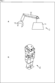
- FIG. 1 is a diagram illustrating an example of an external appearance of a robot according to an embodiment of the present technology.
- the robot 1 shown in FIG. 1A is an arm type robot.
- the robot 1 includes a base unit 11, an arm unit 12 extending from the base unit 11, and a hand unit 13 attached to a tip of the arm unit 12.
- the robot 1 is provided in a factory or the like, and performs a predetermined task such as grasping and moving an object.
- a robot 2 which is a humanoid robot capable of bipedal walking as shown in FIG. 1B may be used.
- the robot 2 also has an arm portion and the like, and can move an object by grasping it.
- the robots 1 and 2 shown in FIG. 1 execute a predetermined program by a built-in computer, and take an autonomous action by driving each part.
- processing performed in the robot 1 which is an arm type robot will be described as appropriate.
- the same processing as the processing performed by the robot 1 is performed by the robot 2 or a robot of another shape such as a robot that can walk on four legs.
- the robot 1 When performing a task such as grabbing and moving an object, the robot 1 monitors its own state at each timing. When the state transition of the robot 1 is following the same transition as the failure state transition that is the state transition leading to the task failure, the robot 1 warns the user before reaching the failure state. Perform an action.
- the robot 1 has failed state transition information that is information indicating failed state transition for each task.
- the failure state transition information is generated in advance at a predetermined timing and prepared in the robot 1.
- the state includes an operation and an event.
- the operation represents an event that the robot 1 actively performs. Events such as “moving the arm” and “recognizing” are included in the operation.
- the event represents a passive event detected in the robot 1. An event such as “lost” is included in the event.
- each state is not represented by a value, but it is determined whether or not the state of the robot 1 corresponds to each state.
- the state includes recognition results such as an image recognition result, an abnormal sound detection result, and an odor detection result.
- the state also includes a recognition result, such as the shape, slipperiness, and softness, of the object specified by gripping the object.
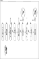
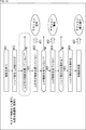
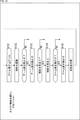
- FIG. 2 is a diagram showing an example of a failed state transition.
- the failure state transition shown in FIG. 2 represents a state transition that leads to failure of the task of “grabbing an object”.
- the task of “grabbing an object” is, for example, a task of recognizing, grasping, and lifting an object placed near the robot 1.
- the state of the robot 1 is first a state # 1 in which the arm unit 12 is raised, and then a state # in which the object to be grasped is recognized # It becomes 2.
- the object to be grasped is recognized based on, for example, an image captured by a camera or sensor data detected by a sensor.
- the state of the robot 1 is the state # 3 in which the arm 12 is moved.
- the robot 1 drives each unit to move the arm unit 12. If the arm unit 12 is not moved, it is treated as not causing a task failure.
- the state of the robot 1 is the state # 4 in which the object to be grasped has been lost.
- a warning action is executed as indicated by the arrow A1.
- the robot 1 drives a speaker or the like to warn the user by voice that the object to be grasped has been lost. If the object to be grasped is not lost, it is treated as not causing a task failure.
- the state becomes the state # 4 in which the object to be grasped is lost, and after the warning action is performed, it is determined whether or not the arm unit 12 is further moved.
- the state of the robot 1 is a state # 5 in which the arm 12 is moved.
- state # 5 When the state is changed to state # 5, it is determined that the task is in a pre-failure state, which is a state before the task reaches a failure, and an emergency stop action is executed as indicated by the arrow A2.
- the robot 1 stops driving each unit and does not move the arm unit 12. By not moving the arm unit 12, the task does not fail.
- the state transition composed of states # 1 to # 5 is set as a failure state transition when the task of “grabbing an object” is executed.
- a warning or emergency stop action is executed.
- the robot 1 can be moved to the pre-failure state by urgently stopping the operation when the user attempts to move the arm unit 12 by following the failed state transition even after losing the object to be grasped and issuing a warning, thereby performing the task 1 Can be prevented, and it is possible to prevent the arm portion 12 or the like from hitting a surrounding object.
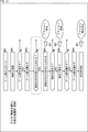
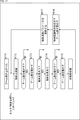
- FIG. 3 is a diagram showing another example of the failure state transition.
- the failure state transition shown in FIG. 3 represents a state transition that leads to the failure of the task of “handing an object to a person”.
- the task of “handing an object to a person” is, for example, a task of holding an object placed in the vicinity of the robot 1, inserting the object forward of a nearby person, and releasing the object to hand the object to the person.
- the state of the robot 1 is first a state # 11 in which the object is held by the hand unit 13, and then the hand unit 13 is put in front of the person.
- State # 12 The operation of holding the object is realized by recognizing the target object based on the output of a sensor such as a camera, and driving the arm unit 12 and the hand unit 13.
- the state of the robot 1 is the state # 13 in which the human hand is not touching the object.
- a warning action is executed as indicated by the arrow A11.
- the robot 1 drives a speaker or the like to warn the user by voice that the hand is not touching the object. If a human hand touches the object, it is treated as if it did not cause the task to fail.
- the state is the state # 13 in which the human hand is not touching the object, and after the warning action is executed, it is determined whether or not the hand 13 is looking at the object that is being put out. Whether or not the user is looking at the object is determined based on, for example, the direction of the line of sight of the person specified by analyzing an image captured by the camera.
- the state of the robot 1 is the state # 14 in which the person does not look at the object.
- a warning action is executed as indicated by the point of the arrow A12.
- the robot 1 drives a speaker or the like to warn the user by voice that he or she concentrates on viewing the object. If a person is looking at the object, it is treated as if the task did not fail.
- the state is state # 14 in which a person is not looking at the object. After the warning action is executed, it is determined whether or not the force of the hand unit 13 holding the object is relaxed.
- the state of the robot 1 is a state # 15 in which the force of the hand unit 13 for grasping an object is relaxed. If the force of the hand unit 13 for gripping the object is not loosened, it is treated as not causing a task failure.
- the state transition consisting of states # 11 to # 15 is set as a failure state transition when the task of “handing an object to a person” is executed.
- a warning or emergency stop action is executed.
- the robot 1 can be brought into a pre-failure state and perform an operation for grasping the object again. Can prevent a task from failing and prevent a falling object from being dropped.
- the failed state transition is set for each task, and information representing such a transition is prepared in the robot 1.
- the robot 1 determines that the task will fail if the transition of its own state follows the same transition as the failure state transition, and performs an optimal operation according to the task before actually failing. , It is possible to prevent failure.
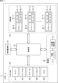
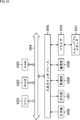
- FIG. 4 is a block diagram illustrating a hardware configuration example of the robot 1.
- the robot 1 is configured by connecting the input / output unit 32, the driving unit 33, the wireless communication unit 34, and the power supply unit 35 to the control unit 31.
- the control unit 31 is configured by a computer having a CPU (Central Processing Unit), a ROM (Read Only Memory), a RAM (Random Access Memory), a flash memory, and the like.
- the control unit 31 executes a predetermined program by the CPU and controls the entire operation of the robot 1.
- the computer constituting the control unit 31 functions as a control device that controls the operation of the robot 1.
- control unit 31 monitors its own state based on information supplied from the input / output unit 32 and information supplied from each drive unit of the drive unit 33.
- control unit 31 determines whether or not the transition of its own state follows the same transition as the failed state transition based on the failed state transition information of the task. When determining that the transition of its own state is following the same transition as the failure state transition, the control unit 31 executes a predetermined action before actually causing a failure.
- the input / output unit 32 includes a camera 41, a microphone (microphone) 42, a speaker 43, a touch sensor 44, and an LED (Light Emitting Diode) 45.
- the camera 41 sequentially captures the surrounding environment.
- the camera 41 outputs data of a captured image, which is a still image or a moving image, obtained by shooting to the control unit 31.
- the microphone 42 detects the environmental sound.
- the microphone 42 outputs environmental sound data to the control unit 31.
- the speaker 43 outputs a predetermined sound such as an uttered voice and BGM.
- the touch sensor 44 is provided at a predetermined portion such as the base unit 11. Touch sensor 44 detects that the user has touched, and outputs information representing the content of the operation by the user to control unit 31.
- the LED 45 emits light under the control of the control unit 31 to present information to the user.
- a small display such as an LCD or an organic EL display may be provided.
- the input / output unit 32 is provided with various modules such as a distance measuring sensor for measuring a distance to a surrounding object and a positioning sensor such as a GPS (Global Positioning System).
- a distance measuring sensor for measuring a distance to a surrounding object
- a positioning sensor such as a GPS (Global Positioning System).
- the driving unit 33 drives according to the control of the control unit 31 to realize the action of the robot 1.
- the drive unit 33 is configured by a plurality of drive units provided for each joint axis such as roll, pitch, and yaw.
- Each drive unit is provided at each joint of the robot 1, for example.
- Each drive unit is configured by a combination of a motor that rotates around an axis, an encoder that detects the rotational position of the motor, and a driver that adaptively controls the rotational position and rotational speed of the motor based on the output of the encoder.
- the hardware configuration of the robot 1 is determined by the number of drive units, the positions of the drive units, and the like.
- the drive units 51-1 to 51-n are provided as drive units.
- the drive unit 51-1 includes a motor 61-1, an encoder 62-1 and a driver 63-1.
- the drive units 51-2 to 51-n have the same configuration as the drive unit 51-1.
- the wireless communication unit 34 is a wireless communication module such as a wireless LAN module and a mobile communication module compatible with LTE (Long Term Evolution).
- the wireless communication unit 34 communicates with an external device such as a server on the Internet.
- the wireless communication unit 34 transmits the data supplied from the control unit 31 to an external device, and receives data transmitted from the external device.
- the power supply unit 35 supplies power to each unit in the robot 1.
- the power supply unit 35 includes a charge battery 71 and a charge / discharge control unit 72 that manages a charge / discharge state of the charge battery 71.
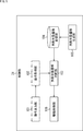
- FIG. 5 is a block diagram showing a functional configuration example of the control unit 31.
- the control unit 31 includes an operation output unit 101, an operation acquisition unit 102, a failure state transition determination unit 103, a failure state transition storage unit 104, a failure state transition generation unit 105, and a drive control unit 106. Is done. At least a part of the functional units shown in FIG. 5 is realized by executing a predetermined program by the CPU constituting the control unit 31.
- the operation output unit 101 receives the information supplied from each drive unit of the drive unit 33 and outputs the information to the operation acquisition unit 102.
- the motion acquisition unit 102 detects the content of the motion of the robot 1 based on the information supplied from the motion output unit 101.
- the operation acquisition unit 102 outputs information indicating the content of the operation to the failure state transition determination unit 103.
- the failed state transition determination unit 103 When executing a predetermined task, the failed state transition determination unit 103 reads and acquires information indicating a failed state transition of the task to be executed from the failed state transition storage unit 104.
- the failure state transition determination unit 103 specifies the state of the robot 1 based on the operation represented by the information supplied from the operation acquisition unit 102, and determines whether the transition of its own state follows the same transition as the failure state transition Determine whether or not.
- the failed state transition determination unit 103 controls the drive control unit 106 based on the determination result of the state transition. For example, when the failed state transition determination unit 103 determines that its own state transition does not follow the same transition as the failed state transition, it causes each operation until the task succeeds. In addition, when the failure state transition determination unit 103 determines that its own state transition follows the same transition as the failure state transition, the failure state transition determination unit 103 executes a preset action.
- the failure state transition storage unit 104 stores failure state transition information of each task.
- the failed state transition generation unit 105 sets the failed state transition of each task and generates failed state transition information.
- the failure state transition generation unit 105 outputs the failure state transition information to the failure state transition storage unit 104 and stores the information.
- the drive control unit 106 controls each drive unit of the drive unit 33 based on the information supplied from the failure state transition determination unit 103 to perform a predetermined operation.
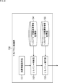
- step S1 the failed state transition generator 105 sets a failed state transition of a predetermined task.
- the setting of the failure state transition may be performed, for example, according to the operation of the administrator of the robot 1.
- step S2 the failed state transition generating unit 105 outputs the failed state transition information to the failed state transition storage unit 104 and stores the information.
- the above processing is performed for each task.
- the failed state transition storage unit 104 stores failed state transition information for each task.
- the failed state transition determination unit 103 specifies the state of the robot 1 based on the operation represented by the information supplied from the operation acquisition unit 102. From the motion acquisition unit 102, information on how the robot 1 is moving (moving the arm unit 12 up, moving forward, etc.) and what information the robot 1 has obtained (image / voice recognition result, other sensor , Etc.) is supplied as information representing the content of the operation.
- step S12 the failed state transition determination unit 103 applies the state of the robot 1 to the failed state transition.
- step S13 the failure state transition determination unit 103 determines whether the state transition of the robot 1 follows the same transition as the failure state transition, and a transition to execute an action has occurred.
- step S13 If it is determined in step S13 that the transition for executing the action has not occurred, the failure state transition determination unit 103 returns to step S11 and repeats the above-described processing.
- step S14 the failure state transition determining unit 103 controls the drive control unit 106 to execute a predetermined action. As described above, depending on the state of the robot 1, actions such as warning to the user, emergency stop of the operation, and re-grip are performed.
- the robot 1 can prevent a task from failing by performing an optimal operation before the task fails.
- the failure state transition may be automatically updated by the robot 1. Updating of the failure state transition is performed, for example, when the number of times that the state has reached the pre-failure state is large.
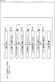
- FIG. 8 is a diagram illustrating a first example of updating a failed state transition related to the task of “grabbing an object”.
- States # 21 to # 23 in FIG. 8 are the same as states # 1 to # 3 in FIG. After the state becomes the state # 23 in which the arm unit 12 is moved, it is determined whether or not the object to be grasped has been lost.
- the state of the robot 1 is a state # 24 in which the object to be grasped has been lost.
- the failure state transition of FIG. 8 As indicated by a broken line, when the state becomes the state # 24 in which the object to be grasped is lost, it is determined that the state before failure has been reached, and The emergency stop action is performed without warning. In other words, the failure state transition is updated so that the failure state is easily reached.
- FIG. 9 is a diagram illustrating a second example of updating the failed state transition related to the task of “grabbing an object”.
- States # 31 to # 33 in FIG. 9 are the same as states # 1 to # 3 in FIG. After the state becomes the state # 33 in which the arm unit 12 is moved, it is determined whether or not more than half of the object to be grasped is out of the angle of view.
- the state of the robot 1 is a state # 34 in which more than half of the object to be grasped is out of the angle of view.
- the robot 1 drives a speaker or the like to warn the user by voice that more than half of the object to be grasped has deviated from the angle of view.
- the warning action is performed based on a stricter standard than the transition in FIG.
- a warning action is executed when it is determined that, for example, the entire object to be grasped has deviated from the angle of view and the object has been lost. Since the state in which half of the object to be grasped deviates from the angle of view is a state that is more likely to occur than the state in which the entire object deviates from the angle of view, the failure state transition in FIG. 9 executes a warning action. It can be said that the standards are strict standards. In other words, the failed state transition is updated so that the failed state transition is easily traced.
- FIG. 10 is a diagram illustrating a first example of updating a failed state transition related to the task of “handing an object to a person”.
- the state is state # 43 in which the human hand is not touching the object, and after the warning action is performed, it is determined whether the human face is not facing the direction of the object.
- the state of the robot 1 is a state # 44 in which the human face is not facing the direction of the object.
- a warning action is executed as indicated by the point of the arrow A42.
- the warning action is performed based on a stricter standard than the transition in FIG.
- a warning action is executed. In other words, regardless of the direction of the face, the warning action is not executed as long as the gaze is directed toward the object.
- the failure state transition in FIG. 10 is a stricter criterion for executing a warning action. It can be said that this is a transition using.
- FIG. 11 is a diagram illustrating a second example of updating a failed state transition related to the task of “handing an object to a person”.
- States # 51 and # 52 in FIG. 11 are the same as states # 11 and # 12 in FIG. After the state # 12 is reached in which the hand unit 13 holding the object is extended to the front of the person, it is determined whether or not the hand of the person is holding the object.
- the state of the robot 1 is the state # 53 where the human hand is not holding the object.
- a warning action is executed as indicated by the point of the arrow A51.
- the warning action is executed based on a stricter standard than the transition in FIG.
- a warning action is executed. In other words, even if the object is not grasped, the warning action is not executed as long as the hand is touched.
- the failure state transition shown in FIG. 10 is a transition using a stricter criterion as a criterion for executing a warning action because the failure state transition is a criterion that requires more human attention in that it not only touches an object but actually grips it. You can say that.
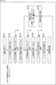
- FIG. 12 is a diagram illustrating another example of updating the failed state transition related to the task of “grabbing an object”.
- the failure state transition shown in FIG. 12 differs from the failure state transition of FIG. 2 in that a state for executing a warning action is added.
- States # 61 and # 62 in FIG. 12 are the same as states # 1 and # 2 in FIG. After the state becomes the state # 63 in which the arm unit 12 is moved, it is determined whether or not more than half of the object to be grasped is out of the angle of view.
- the state of the robot 1 is a state # 64 in which more than half of the object to be grasped is out of the angle of view.
- the transition after the warning action is executed is the same as the transition after state # 3 in FIG.
- the failure state transition is updated so as to increase the number of states in which the action of the warning is performed, so that the failure of the task can be more reliably prevented.
- FIG. 13 is a block diagram illustrating another functional configuration example of the control unit 31.
- FIG. 13 The configuration shown in FIG. 13 is basically the same as the configuration shown in FIG. 5 except that a failed state transition update unit 107 is added. Duplicate descriptions will be omitted as appropriate.
- the failed state transition updating unit 107 determines that it is time to update the failed state transition, the failed state transition updating unit 107 updates the failed state transition as described above. Whether or not it is time to update the failed state transition is determined based on the information supplied from the failed state transition determination unit 103.
- the failure state transition update unit 107 outputs failure state transition information indicating the failure state transition after the update to the failure state transition storage unit 104 and stores it.
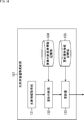
- FIG. 14 is a block diagram illustrating a configuration example of the failure state transition update unit 107.
- the failure state transition update unit 107 includes a failure information acquisition unit 131, an update determination unit 132, an update unit 133, an update determination criterion information storage unit 134, and an update transition information storage unit 135.
- the failure information acquisition unit 131 acquires information related to task failure based on the information output from the failure state transition determination unit 103 (FIG. 13).
- the failure information acquisition unit 131 specifies, for example, the number of times that the state has reached the pre-failure state, and outputs information indicating the specified number of times to the update determination unit 132.
- the update determining unit 132 determines whether to update the failed state transition based on the information supplied from the failure information acquiring unit 131.
- the update criterion information storage unit 134 stores update criterion information serving as a criterion for determining an update for each task.
- Whether or not to update the failed state transition is determined, for example, by comparing the number of times the pre-failure state has been reached with the number of thresholds represented by the update determination criterion information. When the number of times the predetermined task has reached the pre-failure state exceeds the threshold number, the update determining unit 132 determines that the failed state transition of the task is to be updated, and outputs information indicating that to the updating unit 133. .
- the update unit 133 updates the failed state transition determined to be updated based on the information stored in the update transition information storage unit 135.
- the update transition information storage unit 135 stores information on how to update the failed state transition.
- the updating unit 133 outputs and stores the failed state transition information indicating the failed state transition after the update to the failed state transition storage unit 104.
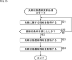
- step S21 the failure information acquisition unit 131 acquires information related to task failure based on the information output from the failure state transition determination unit 103.
- the failure information acquisition unit 131 acquires, as information relating to the failure, the number of times the state has reached the pre-failure state, details of the failure, and the severity of the failure.
- the content of the failure is the cause of the above-mentioned action. For example, losing an object, human hand not touching the object, human not seeing the object, half of the object is out of the angle of view, human face is not facing the object, human hand is the object Is not obtained, is acquired as the content of the failure.
- ⁇ Failure severity is the severity of reaching the pre-failure state. For example, whether there is a collision, whether an object has been dropped, whether an object or a wall has been broken, whether or not it has moved to the limit of the drive area, whether or not a person has been nearby, etc. The corresponding severity is obtained.
- step S22 the update determining unit 132 determines whether or not the update condition of the failed state transition has been satisfied.
- step S22 If it is determined in step S22 that the update condition is not satisfied, the process returns to step S21, and the above processing is repeated.
- step S23 the updating unit 133 updates the failed state transition. Updating of the failed state transition is performed, for example, as in the following 1 to 3.
- updating is performed so as to determine at an early stage that the pre-failure state has been reached, or so that the criterion for executing the action is a stricter criterion.
- the state is updated so that it is determined at an early stage that the state has reached the state before the failure. Further, when the failure of the same content is repeated more than the threshold number of times, or when a failure occurs whose severity is higher than the threshold, the criterion for executing the action is updated to be a stricter criterion.
- the failure state transition of FIG. 8 when the size of the object to be grasped is smaller than a predetermined size, the failure state transition of FIG. 8 is used, and when the size is larger than the predetermined size, the failure state transition of FIG. 9 is used.
- the failure state transition to be used is switched according to the size of the object to be grasped.
- the failure state transition of FIG. 10 is used, and if the person is an adult, the failure state transition of FIG. 11 is used. Is switched according to the attribute of the person to whom the object is to be delivered.
- the user is prompted to update the condition by outputting a sound from the speaker 43 or the like.
- step S24 the updating unit 133 stores the failed state transition information indicating the failed state transition after the update in the failed state transition storage unit 104, and ends the process.
- the robot 1 can more reliably prevent the task from failing.
- the recovery may be executed when the pre-failure state is reached.
- Recovery is an operation that attempts to execute the task again.
- FIG. 16 is a diagram illustrating a first example of a failed state transition including recovery regarding the task of “grabbing an object”.
- the state is the state # 105 in which the arm unit 12 is moved, and if it is determined that the state is the state before the failure, the state of the robot 1 returns to the state # 101 again.
- the robot 1 controls each unit so that the arm unit 12 is in a raised state.
- the recovery is executed by the operation of controlling each unit so that the arm unit 12 is raised.
- FIG. 17 is a diagram illustrating a second example of a failure state transition including recovery regarding the task of “grabbing an object”.
- the state becomes the state # 115 in which the arm unit 12 is moved, and when it is determined that the state is before the failure, the robot 1 moves the arm unit 12 to the position where the object is recognized.
- the state is the state # 116.
- the robot 1 controls each unit to move the arm unit 12 to a position immediately before losing an object.
- the object tracking parameter is a parameter for tracking an object based on an image captured by the camera 41.
- the object tracking parameter includes information such as the moving speed of the arm 12.
- the robot 1 updates the object tracking parameters by lowering the moving speed of the arm unit 12 so as not to lose sight of the object. Thereafter, the state of the robot 1 returns to the state # 112, and the same state transition is continued. In the example of FIG. 17, the recovery is executed by the operation of moving the arm unit 12 to a position immediately before losing the object and updating the object tracking parameter.
- FIG. 18 is a diagram illustrating a first example of a failure state transition including recovery relating to the task of “handing an object to a person”.
- the state is the state # 125 in which the force of the hand unit 13 gripping the object is relaxed, and if it is determined that the state is before the failure, the state of the robot 1 returns to the state # 121 again.
- the robot 1 controls each unit including the hand unit 13 so as to hold the object. I do.
- the recovery is executed by the operation of controlling each unit including the hand unit 13 so as to hold the object.
- FIG. 19 is a diagram illustrating a second example of the failure state transition including recovery regarding the task of “handing an object to a person”.
- the state is a state # 135 in which the force of the hand unit 13 gripping the object is relaxed, and if it is determined that the state is before failure, the state of the robot 1 is a state in which the object is gripped again. It becomes # 136.
- the robot 1 controls each unit including the hand unit 13 so as to grasp the object again.
- the state of the robot 1 is the state # 137 in which the user is warned to look at the object and to hold it with care. After giving such a warning by outputting a sound from the speaker 43 or the like, the robot 1 determines whether or not the person is looking at the object, and repeats the same state transition.
- recovery is executed by an operation of controlling each unit including the hand unit 13 so as to grasp the object again and giving a warning to the user.
- the failure state transition including the recovery is managed in the robot 1, and the recovery is executed when the robot 1 reaches the pre-failure state. Thereby, the robot 1 can prevent the task from failing and guide the task to success.
- the recovery may be performed after the warning is issued.
- FIG. 20 is a block diagram illustrating another functional configuration example of the control unit 31.
- FIG. 20 The configuration shown in FIG. 20 is basically the same as the configuration shown in FIG. 5 except that a recovery control unit 108 is added. Duplicate descriptions will be omitted as appropriate.
- the recovery control unit 108 determines that the state before the failure has been reached, the recovery control unit 108 controls the drive control unit 106 to execute the recovery. Whether the state has reached the pre-failure state is determined based on the information supplied from the failed state transition determination unit 103 or the information supplied from the drive control unit 106.
- FIG. 21 is a block diagram showing a configuration example of the recovery control unit 108.
- the recovery control unit 108 includes a failure information acquisition unit 151, a recovery determination unit 152, a recovery execution unit 153, a recovery criterion information storage unit 154, and a recovery state transition information storage unit 155.
- the failure information acquisition unit 151 acquires information on task failure based on information output from the failure state transition determination unit 103 or the drive control unit 106.
- the failure information acquisition unit 151 specifies, for example, the number of times the state has reached the pre-failure state, and outputs information indicating the specified number of times to the recovery determination unit 152.
- the recovery determination unit 152 determines whether or not to execute recovery based on the information supplied from the failure information acquisition unit 151.
- the recovery criterion information storage unit 154 stores recovery criterion information as a criterion for determining whether or not to execute recovery for each task.
- Whether or not to execute recovery is determined, for example, by comparing the number of times the pre-failure state has been reached with the number of times of the threshold represented by the recovery criterion information. When the number of times the predetermined task has reached the pre-failure state exceeds the threshold, the recovery determination unit 152 determines that recovery is to be performed, and outputs information indicating that to the recovery execution unit 153.
- the recovery execution unit 153 executes recovery based on the information stored in the recovery state transition information storage unit 155.
- the recovery state transition information storage unit 155 stores information on a failed state transition including a recovery state.
- the failure information acquisition unit 151 acquires the information on the failure of the task output from the failure state transition determination unit 103. For example, the failure information acquisition unit 151 acquires, as information relating to the failure, the number of times the state has reached the pre-failure state, the content of the failure, and the severity of the failure.
- step S32 the recovery determining unit 152 determines whether to execute recovery.
- the threshold number if the number of times that the state has reached the pre-failure state is equal to or greater than the threshold number, it is determined that recovery is to be performed. When a failure whose severity is lower than the threshold value occurs, it is determined that recovery is to be performed.
- step S33 the recovery execution unit 153 performs the recovery.
- step S34 the recovery execution unit 153 controls the drive control unit 106 to execute a predetermined action.
- the robot 1 can prevent the task from failing by executing the recovery before the task fails.
- the failure state transition may not be generated by the robot 1 itself, but may be generated by the robot 1 in response to an operation by the user. Further, failure state transition information generated in response to an operation by a user in an external device such as a PC may be provided to the robot 1 and used in the above-described processing.
- Failure state transition information may be generated based on the failure state transition generated in the test stage of the operation of the robot 1 and provided to the robot 1. Information on what state transition is a failed state transition is specified by, for example, a user.
- the user may set a state to be prevented from occurring, and the failure state transition information may be generated based on the state.
- the operation of the robot 1 based on the failure state transition may be performed by an external device such as a server on the Internet.
- FIG. 23 is a diagram showing a configuration example of a control system.
- the control system in FIG. 23 is configured by connecting the robot 1 and the control server 201 via a network 202 such as the Internet.
- the robot 1 and the control server 201 communicate via a network 202.
- the state of the robot 1 is specified by the control server 201 based on information transmitted from the robot 1.
- Information indicating the state of each device of the robot 1 is sequentially transmitted from the robot 1 to the control server 201.
- the control server 201 controls the robot 1 to execute an action according to the state such as a warning action, an action at the time of task failure, and the like. .
- control server 201 functions as a control device that monitors the state of the robot 1 and controls the operation of the robot 1 according to the state.
- each functional unit of FIG. 5, FIG. 14, or FIG. 20 is realized by executing a predetermined program.
- FIG. 24 is a block diagram illustrating a configuration example of hardware of a computer that executes the series of processes described above by a program.
- the control server 201 in FIG. 23 has a configuration similar to the configuration shown in FIG.
- a CPU Central Processing Unit
- ROM Read Only Memory
- RAM Random Access Memory
- the input / output interface 1005 is further connected to the bus 1004.
- the input / output interface 1005 is connected to an input unit 1006 including a keyboard and a mouse, and an output unit 1007 including a display and a speaker.
- a storage unit 1008 such as a hard disk or a non-volatile memory
- a communication unit 1009 such as a network interface
- a drive 1010 for driving the removable medium 1011 are connected to the input / output interface 1005.
- the CPU 1001 loads a program stored in the storage unit 1008 into the RAM 1003 via the input / output interface 1005 and the bus 1004 and executes the program, for example, to execute the above-described series of processing. Is performed.
- the program executed by the CPU 1001 is recorded on the removable medium 1011 or provided via a wired or wireless transmission medium such as a local area network, the Internet, or digital broadcasting, and is installed in the storage unit 1008.
- a wired or wireless transmission medium such as a local area network, the Internet, or digital broadcasting
- the program executed by the computer may be a program in which processing is performed in chronological order in the order described in this specification, or may be performed in parallel or at a necessary timing such as when a call is made. It may be a program that performs processing.
- a system means a set of a plurality of components (devices, modules (parts), etc.), and it does not matter whether all components are in the same housing. Therefore, a plurality of devices housed in separate housings and connected via a network and one device housing a plurality of modules in one housing are all systems. .
- the present technology can adopt a configuration of cloud computing in which one function is shared by a plurality of devices via a network, and processing is performed jointly.
- each step described in the above-described flowchart can be executed by one device, or can be executed by being shared by a plurality of devices.
- one step includes a plurality of processes
- the plurality of processes included in the one step can be executed by one device or can be shared and executed by a plurality of devices.
- the present technology can also have the following configurations.
- a control device comprising a state transition determining unit that controls an operation of the robot.
- the predetermined process is a warning to a user and an emergency stop of an operation of the robot.
- the state transition determination unit after issuing a warning to the user as the predetermined processing, if the state transition of the robot follows the failed state transition, urgently stops the operation of the robot (2).
- the control device according to item 1.
- the control device according to any one of (1) to (3), further including an update unit that updates the failed state transition when the state transition of the robot follows the failed state transition.
- the update unit updates the failed state transition when the number of times the failed state transition is followed exceeds a threshold number of times or according to the content of the state transition of the robot that has followed the failed state transition.
- the control device according to (4).
- (6) The control device according to (4) or (5), wherein the update unit updates the failed state transition so that the state transition of the robot easily follows the failed state transition.
- the control device according to any one of (1) to (6), further including a recovery control unit that controls the robot so as to execute recovery when the state transition of the robot follows the failure state transition.
- the control device (8) The control device according to (7), wherein the recovery control unit causes the recovery to be performed after the predetermined processing is performed. (9) The control device according to any one of (1) to (8), further including a storage unit that stores information indicating the failed state transition. (10) The control device is When the transition of the state of the robot at the time of execution of the task follows a failure state transition set in advance as a state transition leading to the failure of the task, a predetermined process is performed before the failure of the task occurs. A control method for controlling the operation of the robot. (11) On the computer, When the transition of the state of the robot at the time of execution of the task follows a failure state transition set in advance as a state transition leading to the failure of the task, a predetermined process is performed before the failure of the task occurs. A program for executing processing for controlling the operation of the robot.
Landscapes
- Engineering & Computer Science (AREA)
- Robotics (AREA)
- Mechanical Engineering (AREA)
- Physics & Mathematics (AREA)
- General Physics & Mathematics (AREA)
- Automation & Control Theory (AREA)
- Manipulator (AREA)
Abstract
Description
1.失敗状態遷移
2.ロボットの構成例
3.ロボットの動作
4.失敗状態遷移を更新する例
5.リカバリーの例
6.変形例
図1は、本技術の一実施形態に係るロボットの外観の例を示す図である。
図4は、ロボット1のハードウェア構成例を示すブロック図である。
ここで、以上のような構成を有するロボット1の動作について説明する。
失敗状態遷移がロボット1により自動的に更新されるようにしてもよい。失敗状態遷移の更新は、例えば、失敗前状態に至った回数が多い場合に行われる。
図8は、「物体を掴む」のタスクに関する失敗状態遷移の更新の第1の例を示す図である。
図9は、「物体を掴む」のタスクに関する失敗状態遷移の更新の第2の例を示す図である。
図10は、「物体を人に渡す」のタスクに関する失敗状態遷移の更新の第1の例を示す図である。
図11は、「物体を人に渡す」のタスクに関する失敗状態遷移の更新の第2の例を示す図である。
図12は、「物体を掴む」のタスクに関する失敗状態遷移の更新の他の例を示す図である。
図13は、制御部31の他の機能構成例を示すブロック図である。
図15のフローチャートを参照して、失敗状態遷移を更新するロボット1の処理について説明する。
失敗前状態に至った場合にリカバリーが実行されるようにしてもよい。リカバリーは、タスクの実行を再度試みる動作である。
図16は、「物体を掴む」のタスクに関する、リカバリーを含む失敗状態遷移の第1の例を示す図である。
図17は、「物体を掴む」のタスクに関する、リカバリーを含む失敗状態遷移の第2の例を示す図である。
図18は、「物体を人に渡す」のタスクに関する、リカバリーを含む失敗状態遷移の第1の例を示す図である。
図19は、「物体を人に渡す」のタスクに関する、リカバリーを含む失敗状態遷移の第2の例を示す図である。
図20は、制御部31の他の機能構成例を示すブロック図である。
図22のフローチャートを参照して、リカバリーを実行するロボット1の処理について説明する。
失敗状態遷移をロボット1自身が生成するのではなく、ユーザによる操作に応じてロボット1において生成されるようにしてもよい。また、PCなどの外部の装置においてユーザによる操作に応じて生成された失敗状態遷移情報がロボット1に提供され、上述したような処理に用いられるようにしてもよい。
失敗状態遷移に基づくロボット1の動作が、インターネット上のサーバなどの外部の装置により行われるようにしてもよい。
上述した一連の処理は、ハードウェアにより実行することもできるし、ソフトウェアにより実行することもできる。一連の処理をソフトウェアにより実行する場合には、そのソフトウェアを構成するプログラムが、専用のハードウェアに組み込まれているコンピュータ、または汎用のパーソナルコンピュータなどに、プログラム記録媒体からインストールされる。
本技術は、以下のような構成をとることもできる。
タスクの実行時のロボットの状態の遷移が、前記タスクの失敗に至る状態遷移として予め設定された失敗状態遷移を辿っている場合、前記タスクの失敗に至る前に、所定の処理を行うように前記ロボットの動作を制御する状態遷移判断部を備える
制御装置。
(2)
前記所定の処理は、ユーザに対する警告、前記ロボットの動作の緊急停止である
前記(1)に記載の制御装置。
(3)
前記状態遷移判断部は、前記所定の処理としてのユーザに対する警告を行った後に、前記ロボットの状態の遷移が前記失敗状態遷移を辿っている場合、前記ロボットの動作を緊急停止させる
前記(2)に記載の制御装置。
(4)
前記ロボットの状態の遷移が前記失敗状態遷移を辿った場合、前記失敗状態遷移を更新する更新部をさらに備える
前記(1)乃至(3)のいずれかに記載の制御装置。
(5)
前記更新部は、前記失敗状態遷移を辿った回数が閾値の回数を超えた場合、または、前記失敗状態遷移を辿った前記ロボットの状態の遷移の内容に応じて、前記失敗状態遷移を更新する
前記(4)に記載の制御装置。
(6)
前記更新部は、前記ロボットの状態の遷移が前記失敗状態遷移を辿りやすくなるように前記失敗状態遷移を更新する
前記(4)または(5)に記載の制御装置。
(7)
前記ロボットの状態の遷移が前記失敗状態遷移を辿った場合、リカバリーを実行するように前記ロボットを制御するリカバリー制御部をさらに備える
前記(1)乃至(6)のいずれかに記載の制御装置。
(8)
前記リカバリー制御部は、前記所定の処理が行われた後に、前記リカバリーを実行させる
前記(7)に記載の制御装置。
(9)
前記失敗状態遷移を表す情報を記憶する記憶部をさらに備える
前記(1)乃至(8)のいずれかに記載の制御装置。
(10)
制御装置が、
タスクの実行時のロボットの状態の遷移が、前記タスクの失敗に至る状態遷移として予め設定された失敗状態遷移を辿っている場合、前記タスクの失敗に至る前に、所定の処理を行うように前記ロボットの動作を制御する
制御方法。
(11)
コンピュータに、
タスクの実行時のロボットの状態の遷移が、前記タスクの失敗に至る状態遷移として予め設定された失敗状態遷移を辿っている場合、前記タスクの失敗に至る前に、所定の処理を行うように前記ロボットの動作を制御する
処理を実行させるためのプログラム。
Claims (11)
- タスクの実行時のロボットの状態の遷移が、前記タスクの失敗に至る状態遷移として予め設定された失敗状態遷移を辿っている場合、前記タスクの失敗に至る前に、所定の処理を行うように前記ロボットの動作を制御する状態遷移判断部を備える
制御装置。 - 前記所定の処理は、ユーザに対する警告、前記ロボットの動作の緊急停止である
請求項1に記載の制御装置。 - 前記状態遷移判断部は、前記所定の処理としてのユーザに対する警告を行った後に、前記ロボットの状態の遷移が前記失敗状態遷移を辿っている場合、前記ロボットの動作を緊急停止させる
請求項2に記載の制御装置。 - 前記ロボットの状態の遷移が前記失敗状態遷移を辿った場合、前記失敗状態遷移を更新する更新部をさらに備える
請求項1に記載の制御装置。 - 前記更新部は、前記失敗状態遷移を辿った回数が閾値の回数を超えた場合、または、前記失敗状態遷移を辿った前記ロボットの状態の遷移の内容に応じて、前記失敗状態遷移を更新する
請求項4に記載の制御装置。 - 前記更新部は、前記ロボットの状態の遷移が前記失敗状態遷移を辿りやすくなるように前記失敗状態遷移を更新する
請求項4に記載の制御装置。 - 前記ロボットの状態の遷移が前記失敗状態遷移を辿った場合、リカバリーを実行するように前記ロボットを制御するリカバリー制御部をさらに備える
請求項1に記載の制御装置。 - 前記リカバリー制御部は、前記所定の処理が行われた後に、前記リカバリーを実行させる
請求項7に記載の制御装置。 - 前記失敗状態遷移を表す情報を記憶する記憶部をさらに備える
請求項1に記載の制御装置。 - 制御装置が、
タスクの実行時のロボットの状態の遷移が、前記タスクの失敗に至る状態遷移として予め設定された失敗状態遷移を辿っている場合、前記タスクの失敗に至る前に、所定の処理を行うように前記ロボットの動作を制御する
制御方法。 - コンピュータに、
タスクの実行時のロボットの状態の遷移が、前記タスクの失敗に至る状態遷移として予め設定された失敗状態遷移を辿っている場合、前記タスクの失敗に至る前に、所定の処理を行うように前記ロボットの動作を制御する
処理を実行させるためのプログラム。
Priority Applications (4)
| Application Number | Priority Date | Filing Date | Title |
|---|---|---|---|
| US17/263,854 US12233556B2 (en) | 2018-08-08 | 2019-07-25 | Control device, control method, and program |
| CN201980051303.7A CN112512763B (zh) | 2018-08-08 | 2019-07-25 | 控制装置、控制方法和程序 |
| JP2020536453A JP7310820B2 (ja) | 2018-08-08 | 2019-07-25 | 制御装置、制御方法、およびプログラム |
| EP19846081.8A EP3835008A4 (en) | 2018-08-08 | 2019-07-25 | CONTROL DEVICE, CONTROL METHOD AND PROGRAM |
Applications Claiming Priority (2)
| Application Number | Priority Date | Filing Date | Title |
|---|---|---|---|
| JP2018149106 | 2018-08-08 | ||
| JP2018-149106 | 2018-08-08 |
Publications (1)
| Publication Number | Publication Date |
|---|---|
| WO2020031718A1 true WO2020031718A1 (ja) | 2020-02-13 |
Family
ID=69414110
Family Applications (1)
| Application Number | Title | Priority Date | Filing Date |
|---|---|---|---|
| PCT/JP2019/029181 Ceased WO2020031718A1 (ja) | 2018-08-08 | 2019-07-25 | 制御装置、制御方法、およびプログラム |
Country Status (5)
| Country | Link |
|---|---|
| US (1) | US12233556B2 (ja) |
| EP (1) | EP3835008A4 (ja) |
| JP (1) | JP7310820B2 (ja) |
| CN (1) | CN112512763B (ja) |
| WO (1) | WO2020031718A1 (ja) |
Cited By (2)
| Publication number | Priority date | Publication date | Assignee | Title |
|---|---|---|---|---|
| CN116880293A (zh) * | 2023-07-20 | 2023-10-13 | 济南大学 | 一种基于显式模型预测控制的四足机器人控制方法及控制终端 |
| EP4144489A4 (en) * | 2020-04-28 | 2023-10-18 | Sony Group Corporation | Control device, control method, and computer program |
Families Citing this family (3)
| Publication number | Priority date | Publication date | Assignee | Title |
|---|---|---|---|---|
| JP7388352B2 (ja) * | 2018-07-13 | 2023-11-29 | ソニーグループ株式会社 | 制御装置、制御方法、およびプログラム |
| EP4114622A1 (en) | 2020-03-06 | 2023-01-11 | Embodied Intelligence Inc. | Imaging process for detecting failure modes |
| US20250001597A1 (en) * | 2023-06-29 | 2025-01-02 | Intel Corporation | Collaborative human-robot error correction and facilitation |
Citations (9)
| Publication number | Priority date | Publication date | Assignee | Title |
|---|---|---|---|---|
| DE19625637A1 (de) * | 1996-06-26 | 1998-01-02 | Brink Carsten Dipl Ing Ten | Kollisionsvermeidung und Trajektorienplanung beim Mehrroboterbetrieb mit Hilfe von Kollisionsbereichen |
| JPH1165649A (ja) | 1997-08-20 | 1999-03-09 | Yaskawa Electric Corp | センサデータのモニタリング方法 |
| JPH11188680A (ja) * | 1997-12-22 | 1999-07-13 | Matsushita Electric Works Ltd | 部品組付装置 |
| JP2003291083A (ja) * | 2002-03-28 | 2003-10-14 | Toshiba Corp | ロボット装置、ロボット制御方法及びロボット配送システム |
| JP2007303866A (ja) | 2006-05-09 | 2007-11-22 | Sanki Eng Co Ltd | 工場、プラント等における生産設備機器等の運転状態監視システム |
| JP2012073769A (ja) | 2010-09-28 | 2012-04-12 | Kawai Musical Instr Mfg Co Ltd | 楽譜認識装置及びコンピュータプログラム |
| JP2015231640A (ja) * | 2014-06-09 | 2015-12-24 | キヤノン株式会社 | ロボット動作経路チェック装置、ロボットシステム、ロボット動作経路チェック方法、プログラム及び記録媒体 |
| JP2016155212A (ja) * | 2015-02-26 | 2016-09-01 | キヤノン株式会社 | ロボット装置 |
| WO2018012446A1 (ja) * | 2016-07-11 | 2018-01-18 | Groove X株式会社 | 活動量をコントロールされる自律行動型ロボット |
Family Cites Families (13)
| Publication number | Priority date | Publication date | Assignee | Title |
|---|---|---|---|---|
| JP2003260685A (ja) * | 2002-03-04 | 2003-09-16 | Seiko Epson Corp | ロボット制御方法、ロボット制御装置及び制御プログラム |
| DE112010000775B4 (de) * | 2009-02-12 | 2016-03-17 | Kyoto University | Industrierobotersystem |
| US8818556B2 (en) | 2011-01-13 | 2014-08-26 | Microsoft Corporation | Multi-state model for robot and user interaction |
| JP2012232363A (ja) * | 2011-04-28 | 2012-11-29 | Seiko Epson Corp | ロボット制御システム、ロボットシステム及びプログラム |
| US9561590B1 (en) * | 2013-06-24 | 2017-02-07 | Redwood Robotics, Inc. | Distributed system for management and analytics of robotics devices |
| FR3012425B1 (fr) * | 2013-10-24 | 2017-03-24 | European Aeronautic Defence & Space Co Eads France | Robot collaboratif d'inspection visuelle d'un aeronef |
| JP6459227B2 (ja) * | 2014-06-02 | 2019-01-30 | セイコーエプソン株式会社 | ロボットシステム |
| US20160255969A1 (en) * | 2015-03-06 | 2016-09-08 | Wal-Mart Stores, Inc. | Shopping facility assistance systems, devices and methods pertaining to movement of a mobile retail product display |
| JP6219890B2 (ja) * | 2015-07-17 | 2017-10-25 | ファナック株式会社 | ロボットによる自動組立システム |
| WO2017163251A2 (en) | 2016-03-24 | 2017-09-28 | Polygon T.R Ltd. | Systems and methods for human and robot collaboration |
| DE102016125408A1 (de) * | 2016-12-22 | 2018-06-28 | RobArt GmbH | Autonomer mobiler roboter und verfahren zum steuern eines autonomen mobilen roboters |
| JP6889631B2 (ja) * | 2017-08-04 | 2021-06-18 | 川崎重工業株式会社 | 状態監視システム及び状態監視方法 |
| EP3785866B1 (en) * | 2018-04-26 | 2023-12-20 | Panasonic Holdings Corporation | Actuator device, method for removing target object using actuator device, and target object removal system |
-
2019
- 2019-07-25 US US17/263,854 patent/US12233556B2/en active Active
- 2019-07-25 JP JP2020536453A patent/JP7310820B2/ja active Active
- 2019-07-25 WO PCT/JP2019/029181 patent/WO2020031718A1/ja not_active Ceased
- 2019-07-25 EP EP19846081.8A patent/EP3835008A4/en not_active Withdrawn
- 2019-07-25 CN CN201980051303.7A patent/CN112512763B/zh active Active
Patent Citations (9)
| Publication number | Priority date | Publication date | Assignee | Title |
|---|---|---|---|---|
| DE19625637A1 (de) * | 1996-06-26 | 1998-01-02 | Brink Carsten Dipl Ing Ten | Kollisionsvermeidung und Trajektorienplanung beim Mehrroboterbetrieb mit Hilfe von Kollisionsbereichen |
| JPH1165649A (ja) | 1997-08-20 | 1999-03-09 | Yaskawa Electric Corp | センサデータのモニタリング方法 |
| JPH11188680A (ja) * | 1997-12-22 | 1999-07-13 | Matsushita Electric Works Ltd | 部品組付装置 |
| JP2003291083A (ja) * | 2002-03-28 | 2003-10-14 | Toshiba Corp | ロボット装置、ロボット制御方法及びロボット配送システム |
| JP2007303866A (ja) | 2006-05-09 | 2007-11-22 | Sanki Eng Co Ltd | 工場、プラント等における生産設備機器等の運転状態監視システム |
| JP2012073769A (ja) | 2010-09-28 | 2012-04-12 | Kawai Musical Instr Mfg Co Ltd | 楽譜認識装置及びコンピュータプログラム |
| JP2015231640A (ja) * | 2014-06-09 | 2015-12-24 | キヤノン株式会社 | ロボット動作経路チェック装置、ロボットシステム、ロボット動作経路チェック方法、プログラム及び記録媒体 |
| JP2016155212A (ja) * | 2015-02-26 | 2016-09-01 | キヤノン株式会社 | ロボット装置 |
| WO2018012446A1 (ja) * | 2016-07-11 | 2018-01-18 | Groove X株式会社 | 活動量をコントロールされる自律行動型ロボット |
Non-Patent Citations (1)
| Title |
|---|
| See also references of EP3835008A4 |
Cited By (3)
| Publication number | Priority date | Publication date | Assignee | Title |
|---|---|---|---|---|
| EP4144489A4 (en) * | 2020-04-28 | 2023-10-18 | Sony Group Corporation | Control device, control method, and computer program |
| CN116880293A (zh) * | 2023-07-20 | 2023-10-13 | 济南大学 | 一种基于显式模型预测控制的四足机器人控制方法及控制终端 |
| CN116880293B (zh) * | 2023-07-20 | 2023-12-26 | 济南大学 | 一种基于显式模型预测控制的四足机器人控制方法及控制终端 |
Also Published As
| Publication number | Publication date |
|---|---|
| CN112512763B (zh) | 2024-11-29 |
| EP3835008A4 (en) | 2022-04-13 |
| JP7310820B2 (ja) | 2023-07-19 |
| CN112512763A (zh) | 2021-03-16 |
| EP3835008A1 (en) | 2021-06-16 |
| JPWO2020031718A1 (ja) | 2021-08-10 |
| US20210229284A1 (en) | 2021-07-29 |
| US12233556B2 (en) | 2025-02-25 |
Similar Documents
| Publication | Publication Date | Title |
|---|---|---|
| WO2020031718A1 (ja) | 制御装置、制御方法、およびプログラム | |
| JP6462008B2 (ja) | 衝突検出 | |
| CA2953246C (en) | Standby mode of a humanoid robot | |
| JP7156397B2 (ja) | 制御装置 | |
| JP2015507263A5 (ja) | ||
| CN108284434B (zh) | 机器学习装置、示教装置的冲击抑制系统及机器学习方法 | |
| JP7633404B2 (ja) | ロボットの動作プログラムを管理する管理装置、ネットワークシステム、及び方法 | |
| JP2024114146A (ja) | 情報処理装置、情報処理方法およびプログラム | |
| JP7822401B2 (ja) | 作業管理システム、学習装置、推論装置、制御方法及びプログラム | |
| JP7388562B2 (ja) | 制御装置、制御方法及びプログラム | |
| CN121870749A (zh) | 机器人的异常确定方法、装置和非易失性存储介质 | |
| WO2025182029A1 (ja) | シミュレーション装置及びプログラム | |
| TH2001006755A (th) | ระบบควบคุม ตัวควบคุมและวิธีการควบคุม | |
| Poletti | Teleoperation of an underactuated bionic hand: comparison between wearable and vision-based motion tracking methods | |
| Suzuki et al. | A multi-layered hierarchical architecture for a humanoid robot | |
| HK1236890A1 (zh) | 碰撞检测 |
Legal Events
| Date | Code | Title | Description |
|---|---|---|---|
| 121 | Ep: the epo has been informed by wipo that ep was designated in this application |
Ref document number: 19846081 Country of ref document: EP Kind code of ref document: A1 |
|
| ENP | Entry into the national phase |
Ref document number: 2020536453 Country of ref document: JP Kind code of ref document: A |
|
| NENP | Non-entry into the national phase |
Ref country code: DE |
|
| ENP | Entry into the national phase |
Ref document number: 2019846081 Country of ref document: EP Effective date: 20210309 |
|
| WWG | Wipo information: grant in national office |
Ref document number: 17263854 Country of ref document: US |