WO2020031912A1 - 車両用表示システム及び車両 - Google Patents
車両用表示システム及び車両 Download PDFInfo
- Publication number
- WO2020031912A1 WO2020031912A1 PCT/JP2019/030570 JP2019030570W WO2020031912A1 WO 2020031912 A1 WO2020031912 A1 WO 2020031912A1 JP 2019030570 W JP2019030570 W JP 2019030570W WO 2020031912 A1 WO2020031912 A1 WO 2020031912A1
- Authority
- WO
- WIPO (PCT)
- Prior art keywords
- vehicle
- information
- display
- light pattern
- occupant
- Prior art date
- Legal status (The legal status is an assumption and is not a legal conclusion. Google has not performed a legal analysis and makes no representation as to the accuracy of the status listed.)
- Ceased
Links
Images


Classifications
-
- B—PERFORMING OPERATIONS; TRANSPORTING
- B60—VEHICLES IN GENERAL
- B60Q—ARRANGEMENT OF SIGNALLING OR LIGHTING DEVICES, THE MOUNTING OR SUPPORTING THEREOF OR CIRCUITS THEREFOR, FOR VEHICLES IN GENERAL
- B60Q9/00—Arrangement or adaptation of signal devices not provided for in one of main groups B60Q1/00 - B60Q7/00, e.g. haptic signalling
-
- B—PERFORMING OPERATIONS; TRANSPORTING
- B60—VEHICLES IN GENERAL
- B60K—ARRANGEMENT OR MOUNTING OF PROPULSION UNITS OR OF TRANSMISSIONS IN VEHICLES; ARRANGEMENT OR MOUNTING OF PLURAL DIVERSE PRIME-MOVERS IN VEHICLES; AUXILIARY DRIVES FOR VEHICLES; INSTRUMENTATION OR DASHBOARDS FOR VEHICLES; ARRANGEMENTS IN CONNECTION WITH COOLING, AIR INTAKE, GAS EXHAUST OR FUEL SUPPLY OF PROPULSION UNITS IN VEHICLES
- B60K35/00—Instruments specially adapted for vehicles; Arrangement of instruments in or on vehicles
- B60K35/20—Output arrangements, i.e. from vehicle to user, associated with vehicle functions or specially adapted therefor
- B60K35/28—Output arrangements, i.e. from vehicle to user, associated with vehicle functions or specially adapted therefor characterised by the type of the output information, e.g. video entertainment or vehicle dynamics information; characterised by the purpose of the output information, e.g. for attracting the attention of the driver
-
- B—PERFORMING OPERATIONS; TRANSPORTING
- B60—VEHICLES IN GENERAL
- B60K—ARRANGEMENT OR MOUNTING OF PROPULSION UNITS OR OF TRANSMISSIONS IN VEHICLES; ARRANGEMENT OR MOUNTING OF PLURAL DIVERSE PRIME-MOVERS IN VEHICLES; AUXILIARY DRIVES FOR VEHICLES; INSTRUMENTATION OR DASHBOARDS FOR VEHICLES; ARRANGEMENTS IN CONNECTION WITH COOLING, AIR INTAKE, GAS EXHAUST OR FUEL SUPPLY OF PROPULSION UNITS IN VEHICLES
- B60K35/00—Instruments specially adapted for vehicles; Arrangement of instruments in or on vehicles
- B60K35/20—Output arrangements, i.e. from vehicle to user, associated with vehicle functions or specially adapted therefor
- B60K35/29—Instruments characterised by the way in which information is handled, e.g. showing information on plural displays or prioritising information according to driving conditions
-
- B—PERFORMING OPERATIONS; TRANSPORTING
- B60—VEHICLES IN GENERAL
- B60K—ARRANGEMENT OR MOUNTING OF PROPULSION UNITS OR OF TRANSMISSIONS IN VEHICLES; ARRANGEMENT OR MOUNTING OF PLURAL DIVERSE PRIME-MOVERS IN VEHICLES; AUXILIARY DRIVES FOR VEHICLES; INSTRUMENTATION OR DASHBOARDS FOR VEHICLES; ARRANGEMENTS IN CONNECTION WITH COOLING, AIR INTAKE, GAS EXHAUST OR FUEL SUPPLY OF PROPULSION UNITS IN VEHICLES
- B60K35/00—Instruments specially adapted for vehicles; Arrangement of instruments in or on vehicles
- B60K35/60—Instruments characterised by their location or relative disposition in or on vehicles
-
- B—PERFORMING OPERATIONS; TRANSPORTING
- B60—VEHICLES IN GENERAL
- B60Q—ARRANGEMENT OF SIGNALLING OR LIGHTING DEVICES, THE MOUNTING OR SUPPORTING THEREOF OR CIRCUITS THEREFOR, FOR VEHICLES IN GENERAL
- B60Q1/00—Arrangement of optical signalling or lighting devices, the mounting or supporting thereof or circuits therefor
- B60Q1/02—Arrangement of optical signalling or lighting devices, the mounting or supporting thereof or circuits therefor the devices being primarily intended to illuminate the way ahead or to illuminate other areas of way or environments
- B60Q1/04—Arrangement of optical signalling or lighting devices, the mounting or supporting thereof or circuits therefor the devices being primarily intended to illuminate the way ahead or to illuminate other areas of way or environments the devices being headlights
-
- B—PERFORMING OPERATIONS; TRANSPORTING
- B60—VEHICLES IN GENERAL
- B60Q—ARRANGEMENT OF SIGNALLING OR LIGHTING DEVICES, THE MOUNTING OR SUPPORTING THEREOF OR CIRCUITS THEREFOR, FOR VEHICLES IN GENERAL
- B60Q1/00—Arrangement of optical signalling or lighting devices, the mounting or supporting thereof or circuits therefor
- B60Q1/26—Arrangement of optical signalling or lighting devices, the mounting or supporting thereof or circuits therefor the devices being primarily intended to indicate the vehicle, or parts thereof, or to give signals, to other traffic
- B60Q1/50—Arrangement of optical signalling or lighting devices, the mounting or supporting thereof or circuits therefor the devices being primarily intended to indicate the vehicle, or parts thereof, or to give signals, to other traffic for indicating other intentions or conditions, e.g. request for waiting or overtaking
- B60Q1/507—Arrangement of optical signalling or lighting devices, the mounting or supporting thereof or circuits therefor the devices being primarily intended to indicate the vehicle, or parts thereof, or to give signals, to other traffic for indicating other intentions or conditions, e.g. request for waiting or overtaking specific to autonomous vehicles
-
- B—PERFORMING OPERATIONS; TRANSPORTING
- B60—VEHICLES IN GENERAL
- B60Q—ARRANGEMENT OF SIGNALLING OR LIGHTING DEVICES, THE MOUNTING OR SUPPORTING THEREOF OR CIRCUITS THEREFOR, FOR VEHICLES IN GENERAL
- B60Q1/00—Arrangement of optical signalling or lighting devices, the mounting or supporting thereof or circuits therefor
- B60Q1/26—Arrangement of optical signalling or lighting devices, the mounting or supporting thereof or circuits therefor the devices being primarily intended to indicate the vehicle, or parts thereof, or to give signals, to other traffic
- B60Q1/50—Arrangement of optical signalling or lighting devices, the mounting or supporting thereof or circuits therefor the devices being primarily intended to indicate the vehicle, or parts thereof, or to give signals, to other traffic for indicating other intentions or conditions, e.g. request for waiting or overtaking
- B60Q1/543—Arrangement of optical signalling or lighting devices, the mounting or supporting thereof or circuits therefor the devices being primarily intended to indicate the vehicle, or parts thereof, or to give signals, to other traffic for indicating other intentions or conditions, e.g. request for waiting or overtaking for indicating other states or conditions of the vehicle
-
- B—PERFORMING OPERATIONS; TRANSPORTING
- B60—VEHICLES IN GENERAL
- B60Q—ARRANGEMENT OF SIGNALLING OR LIGHTING DEVICES, THE MOUNTING OR SUPPORTING THEREOF OR CIRCUITS THEREFOR, FOR VEHICLES IN GENERAL
- B60Q1/00—Arrangement of optical signalling or lighting devices, the mounting or supporting thereof or circuits therefor
- B60Q1/26—Arrangement of optical signalling or lighting devices, the mounting or supporting thereof or circuits therefor the devices being primarily intended to indicate the vehicle, or parts thereof, or to give signals, to other traffic
- B60Q1/50—Arrangement of optical signalling or lighting devices, the mounting or supporting thereof or circuits therefor the devices being primarily intended to indicate the vehicle, or parts thereof, or to give signals, to other traffic for indicating other intentions or conditions, e.g. request for waiting or overtaking
- B60Q1/547—Arrangement of optical signalling or lighting devices, the mounting or supporting thereof or circuits therefor the devices being primarily intended to indicate the vehicle, or parts thereof, or to give signals, to other traffic for indicating other intentions or conditions, e.g. request for waiting or overtaking for issuing requests to other traffic participants; for confirming to other traffic participants they can proceed, e.g. they can overtake
-
- G—PHYSICS
- G02—OPTICS
- G02B—OPTICAL ELEMENTS, SYSTEMS OR APPARATUS
- G02B27/00—Optical systems or apparatus not provided for by any of the groups G02B1/00 - G02B26/00, G02B30/00
- G02B27/01—Head-up displays
- G02B27/0101—Head-up displays characterised by optical features
-
- G—PHYSICS
- G08—SIGNALLING
- G08G—TRAFFIC CONTROL SYSTEMS
- G08G1/00—Traffic control systems for road vehicles
- G08G1/16—Anti-collision systems
- G08G1/166—Anti-collision systems for active traffic, e.g. moving vehicles, pedestrians, bikes
-
- B—PERFORMING OPERATIONS; TRANSPORTING
- B60—VEHICLES IN GENERAL
- B60K—ARRANGEMENT OR MOUNTING OF PROPULSION UNITS OR OF TRANSMISSIONS IN VEHICLES; ARRANGEMENT OR MOUNTING OF PLURAL DIVERSE PRIME-MOVERS IN VEHICLES; AUXILIARY DRIVES FOR VEHICLES; INSTRUMENTATION OR DASHBOARDS FOR VEHICLES; ARRANGEMENTS IN CONNECTION WITH COOLING, AIR INTAKE, GAS EXHAUST OR FUEL SUPPLY OF PROPULSION UNITS IN VEHICLES
- B60K2360/00—Indexing scheme associated with groups B60K35/00 or B60K37/00 relating to details of instruments or dashboards
- B60K2360/16—Type of output information
- B60K2360/177—Augmented reality
-
- B—PERFORMING OPERATIONS; TRANSPORTING
- B60—VEHICLES IN GENERAL
- B60K—ARRANGEMENT OR MOUNTING OF PROPULSION UNITS OR OF TRANSMISSIONS IN VEHICLES; ARRANGEMENT OR MOUNTING OF PLURAL DIVERSE PRIME-MOVERS IN VEHICLES; AUXILIARY DRIVES FOR VEHICLES; INSTRUMENTATION OR DASHBOARDS FOR VEHICLES; ARRANGEMENTS IN CONNECTION WITH COOLING, AIR INTAKE, GAS EXHAUST OR FUEL SUPPLY OF PROPULSION UNITS IN VEHICLES
- B60K2360/00—Indexing scheme associated with groups B60K35/00 or B60K37/00 relating to details of instruments or dashboards
- B60K2360/16—Type of output information
- B60K2360/179—Distances to obstacles or vehicles
-
- B—PERFORMING OPERATIONS; TRANSPORTING
- B60—VEHICLES IN GENERAL
- B60K—ARRANGEMENT OR MOUNTING OF PROPULSION UNITS OR OF TRANSMISSIONS IN VEHICLES; ARRANGEMENT OR MOUNTING OF PLURAL DIVERSE PRIME-MOVERS IN VEHICLES; AUXILIARY DRIVES FOR VEHICLES; INSTRUMENTATION OR DASHBOARDS FOR VEHICLES; ARRANGEMENTS IN CONNECTION WITH COOLING, AIR INTAKE, GAS EXHAUST OR FUEL SUPPLY OF PROPULSION UNITS IN VEHICLES
- B60K2360/00—Indexing scheme associated with groups B60K35/00 or B60K37/00 relating to details of instruments or dashboards
- B60K2360/20—Optical features of instruments
- B60K2360/33—Illumination features
- B60K2360/334—Projection means
-
- B—PERFORMING OPERATIONS; TRANSPORTING
- B60—VEHICLES IN GENERAL
- B60K—ARRANGEMENT OR MOUNTING OF PROPULSION UNITS OR OF TRANSMISSIONS IN VEHICLES; ARRANGEMENT OR MOUNTING OF PLURAL DIVERSE PRIME-MOVERS IN VEHICLES; AUXILIARY DRIVES FOR VEHICLES; INSTRUMENTATION OR DASHBOARDS FOR VEHICLES; ARRANGEMENTS IN CONNECTION WITH COOLING, AIR INTAKE, GAS EXHAUST OR FUEL SUPPLY OF PROPULSION UNITS IN VEHICLES
- B60K2360/00—Indexing scheme associated with groups B60K35/00 or B60K37/00 relating to details of instruments or dashboards
- B60K2360/20—Optical features of instruments
- B60K2360/33—Illumination features
- B60K2360/347—Optical elements for superposition of display information
-
- B—PERFORMING OPERATIONS; TRANSPORTING
- B60—VEHICLES IN GENERAL
- B60K—ARRANGEMENT OR MOUNTING OF PROPULSION UNITS OR OF TRANSMISSIONS IN VEHICLES; ARRANGEMENT OR MOUNTING OF PLURAL DIVERSE PRIME-MOVERS IN VEHICLES; AUXILIARY DRIVES FOR VEHICLES; INSTRUMENTATION OR DASHBOARDS FOR VEHICLES; ARRANGEMENTS IN CONNECTION WITH COOLING, AIR INTAKE, GAS EXHAUST OR FUEL SUPPLY OF PROPULSION UNITS IN VEHICLES
- B60K2360/00—Indexing scheme associated with groups B60K35/00 or B60K37/00 relating to details of instruments or dashboards
- B60K2360/77—Instrument locations other than the dashboard
- B60K2360/797—Instrument locations other than the dashboard at the vehicle exterior
-
- B—PERFORMING OPERATIONS; TRANSPORTING
- B60—VEHICLES IN GENERAL
- B60K—ARRANGEMENT OR MOUNTING OF PROPULSION UNITS OR OF TRANSMISSIONS IN VEHICLES; ARRANGEMENT OR MOUNTING OF PLURAL DIVERSE PRIME-MOVERS IN VEHICLES; AUXILIARY DRIVES FOR VEHICLES; INSTRUMENTATION OR DASHBOARDS FOR VEHICLES; ARRANGEMENTS IN CONNECTION WITH COOLING, AIR INTAKE, GAS EXHAUST OR FUEL SUPPLY OF PROPULSION UNITS IN VEHICLES
- B60K35/00—Instruments specially adapted for vehicles; Arrangement of instruments in or on vehicles
- B60K35/10—Input arrangements, i.e. from user to vehicle, associated with vehicle functions or specially adapted therefor
-
- B—PERFORMING OPERATIONS; TRANSPORTING
- B60—VEHICLES IN GENERAL
- B60K—ARRANGEMENT OR MOUNTING OF PROPULSION UNITS OR OF TRANSMISSIONS IN VEHICLES; ARRANGEMENT OR MOUNTING OF PLURAL DIVERSE PRIME-MOVERS IN VEHICLES; AUXILIARY DRIVES FOR VEHICLES; INSTRUMENTATION OR DASHBOARDS FOR VEHICLES; ARRANGEMENTS IN CONNECTION WITH COOLING, AIR INTAKE, GAS EXHAUST OR FUEL SUPPLY OF PROPULSION UNITS IN VEHICLES
- B60K35/00—Instruments specially adapted for vehicles; Arrangement of instruments in or on vehicles
- B60K35/20—Output arrangements, i.e. from vehicle to user, associated with vehicle functions or specially adapted therefor
- B60K35/21—Output arrangements, i.e. from vehicle to user, associated with vehicle functions or specially adapted therefor using visual output, e.g. blinking lights or matrix displays
- B60K35/23—Head-up displays [HUD]
- B60K35/231—Head-up displays [HUD] characterised by their arrangement or structure for integration into vehicles
-
- B—PERFORMING OPERATIONS; TRANSPORTING
- B60—VEHICLES IN GENERAL
- B60K—ARRANGEMENT OR MOUNTING OF PROPULSION UNITS OR OF TRANSMISSIONS IN VEHICLES; ARRANGEMENT OR MOUNTING OF PLURAL DIVERSE PRIME-MOVERS IN VEHICLES; AUXILIARY DRIVES FOR VEHICLES; INSTRUMENTATION OR DASHBOARDS FOR VEHICLES; ARRANGEMENTS IN CONNECTION WITH COOLING, AIR INTAKE, GAS EXHAUST OR FUEL SUPPLY OF PROPULSION UNITS IN VEHICLES
- B60K35/00—Instruments specially adapted for vehicles; Arrangement of instruments in or on vehicles
- B60K35/20—Output arrangements, i.e. from vehicle to user, associated with vehicle functions or specially adapted therefor
- B60K35/21—Output arrangements, i.e. from vehicle to user, associated with vehicle functions or specially adapted therefor using visual output, e.g. blinking lights or matrix displays
- B60K35/23—Head-up displays [HUD]
- B60K35/233—Head-up displays [HUD] controlling the size or position in display areas of virtual images depending on the condition of the vehicle or the driver
-
- B—PERFORMING OPERATIONS; TRANSPORTING
- B60—VEHICLES IN GENERAL
- B60K—ARRANGEMENT OR MOUNTING OF PROPULSION UNITS OR OF TRANSMISSIONS IN VEHICLES; ARRANGEMENT OR MOUNTING OF PLURAL DIVERSE PRIME-MOVERS IN VEHICLES; AUXILIARY DRIVES FOR VEHICLES; INSTRUMENTATION OR DASHBOARDS FOR VEHICLES; ARRANGEMENTS IN CONNECTION WITH COOLING, AIR INTAKE, GAS EXHAUST OR FUEL SUPPLY OF PROPULSION UNITS IN VEHICLES
- B60K35/00—Instruments specially adapted for vehicles; Arrangement of instruments in or on vehicles
- B60K35/80—Arrangements for controlling instruments
- B60K35/81—Arrangements for controlling instruments for controlling displays
-
- B—PERFORMING OPERATIONS; TRANSPORTING
- B60—VEHICLES IN GENERAL
- B60Q—ARRANGEMENT OF SIGNALLING OR LIGHTING DEVICES, THE MOUNTING OR SUPPORTING THEREOF OR CIRCUITS THEREFOR, FOR VEHICLES IN GENERAL
- B60Q2300/00—Indexing codes for automatically adjustable headlamps or automatically dimmable headlamps
- B60Q2300/40—Indexing codes relating to other road users or special conditions
- B60Q2300/45—Special conditions, e.g. pedestrians, road signs or potential dangers
-
- B—PERFORMING OPERATIONS; TRANSPORTING
- B60—VEHICLES IN GENERAL
- B60Q—ARRANGEMENT OF SIGNALLING OR LIGHTING DEVICES, THE MOUNTING OR SUPPORTING THEREOF OR CIRCUITS THEREFOR, FOR VEHICLES IN GENERAL
- B60Q2400/00—Special features or arrangements of exterior signal lamps for vehicles
- B60Q2400/50—Projected symbol or information, e.g. onto the road or car body
-
- B—PERFORMING OPERATIONS; TRANSPORTING
- B60—VEHICLES IN GENERAL
- B60R—VEHICLES, VEHICLE FITTINGS, OR VEHICLE PARTS, NOT OTHERWISE PROVIDED FOR
- B60R2300/00—Details of viewing arrangements using cameras and displays, specially adapted for use in a vehicle
- B60R2300/20—Details of viewing arrangements using cameras and displays, specially adapted for use in a vehicle characterised by the type of display used
- B60R2300/205—Details of viewing arrangements using cameras and displays, specially adapted for use in a vehicle characterised by the type of display used using a head-up display
-
- B—PERFORMING OPERATIONS; TRANSPORTING
- B60—VEHICLES IN GENERAL
- B60R—VEHICLES, VEHICLE FITTINGS, OR VEHICLE PARTS, NOT OTHERWISE PROVIDED FOR
- B60R2300/00—Details of viewing arrangements using cameras and displays, specially adapted for use in a vehicle
- B60R2300/20—Details of viewing arrangements using cameras and displays, specially adapted for use in a vehicle characterised by the type of display used
- B60R2300/207—Details of viewing arrangements using cameras and displays, specially adapted for use in a vehicle characterised by the type of display used using multi-purpose displays, e.g. camera image and navigation or video on same display
-
- B—PERFORMING OPERATIONS; TRANSPORTING
- B60—VEHICLES IN GENERAL
- B60R—VEHICLES, VEHICLE FITTINGS, OR VEHICLE PARTS, NOT OTHERWISE PROVIDED FOR
- B60R2300/00—Details of viewing arrangements using cameras and displays, specially adapted for use in a vehicle
- B60R2300/30—Details of viewing arrangements using cameras and displays, specially adapted for use in a vehicle characterised by the type of image processing
- B60R2300/301—Details of viewing arrangements using cameras and displays, specially adapted for use in a vehicle characterised by the type of image processing combining image information with other obstacle sensor information, e.g. using RADAR/LIDAR/SONAR sensors for estimating risk of collision
-
- B—PERFORMING OPERATIONS; TRANSPORTING
- B60—VEHICLES IN GENERAL
- B60R—VEHICLES, VEHICLE FITTINGS, OR VEHICLE PARTS, NOT OTHERWISE PROVIDED FOR
- B60R2300/00—Details of viewing arrangements using cameras and displays, specially adapted for use in a vehicle
- B60R2300/30—Details of viewing arrangements using cameras and displays, specially adapted for use in a vehicle characterised by the type of image processing
- B60R2300/304—Details of viewing arrangements using cameras and displays, specially adapted for use in a vehicle characterised by the type of image processing using merged images, e.g. merging camera image with stored images
- B60R2300/305—Details of viewing arrangements using cameras and displays, specially adapted for use in a vehicle characterised by the type of image processing using merged images, e.g. merging camera image with stored images merging camera image with lines or icons
-
- B—PERFORMING OPERATIONS; TRANSPORTING
- B60—VEHICLES IN GENERAL
- B60R—VEHICLES, VEHICLE FITTINGS, OR VEHICLE PARTS, NOT OTHERWISE PROVIDED FOR
- B60R2300/00—Details of viewing arrangements using cameras and displays, specially adapted for use in a vehicle
- B60R2300/30—Details of viewing arrangements using cameras and displays, specially adapted for use in a vehicle characterised by the type of image processing
- B60R2300/307—Details of viewing arrangements using cameras and displays, specially adapted for use in a vehicle characterised by the type of image processing virtually distinguishing relevant parts of a scene from the background of the scene
- B60R2300/308—Details of viewing arrangements using cameras and displays, specially adapted for use in a vehicle characterised by the type of image processing virtually distinguishing relevant parts of a scene from the background of the scene by overlaying the real scene, e.g. through a head-up display on the windscreen
-
- B—PERFORMING OPERATIONS; TRANSPORTING
- B60—VEHICLES IN GENERAL
- B60R—VEHICLES, VEHICLE FITTINGS, OR VEHICLE PARTS, NOT OTHERWISE PROVIDED FOR
- B60R2300/00—Details of viewing arrangements using cameras and displays, specially adapted for use in a vehicle
- B60R2300/80—Details of viewing arrangements using cameras and displays, specially adapted for use in a vehicle characterised by the intended use of the viewing arrangement
- B60R2300/8033—Details of viewing arrangements using cameras and displays, specially adapted for use in a vehicle characterised by the intended use of the viewing arrangement for pedestrian protection
-
- G—PHYSICS
- G02—OPTICS
- G02B—OPTICAL ELEMENTS, SYSTEMS OR APPARATUS
- G02B27/00—Optical systems or apparatus not provided for by any of the groups G02B1/00 - G02B26/00, G02B30/00
- G02B27/01—Head-up displays
- G02B27/0101—Head-up displays characterised by optical features
- G02B2027/0138—Head-up displays characterised by optical features comprising image capture systems, e.g. camera
-
- G—PHYSICS
- G02—OPTICS
- G02B—OPTICAL ELEMENTS, SYSTEMS OR APPARATUS
- G02B27/00—Optical systems or apparatus not provided for by any of the groups G02B1/00 - G02B26/00, G02B30/00
- G02B27/01—Head-up displays
- G02B27/0101—Head-up displays characterised by optical features
- G02B2027/014—Head-up displays characterised by optical features comprising information/image processing systems
Definitions
- the present disclosure relates to a vehicle display system and a vehicle including the vehicle display system.
- the vehicle system automatically controls traveling of the vehicle. Specifically, in the automatic driving mode, the vehicle system performs steering control based on information indicating the surrounding environment of the vehicle (surrounding environment information) obtained from sensors such as a camera and a radar (for example, a laser radar or a millimeter wave radar). At least one of (control of the traveling direction of the vehicle), brake control, and accelerator control (control of braking and acceleration / deceleration of the vehicle) is automatically performed.
- the driver controls the running of the vehicle as in many conventional vehicles.
- the traveling of the vehicle is controlled according to the driver's operation (steering operation, brake operation, accelerator operation), and the vehicle system does not automatically perform the steering control, the brake control, and the accelerator control.
- the vehicle driving mode is not a concept that exists only in some vehicles, but a concept that exists in all vehicles including a conventional vehicle that does not have an automatic driving function. Classified according to the method.
- autonomous driving vehicles vehicles traveling in the automatic driving mode
- manual driving vehicles vehicles traveling in the manual driving mode
- Patent Literature 1 discloses an automatic following system in which a following vehicle automatically runs following a preceding vehicle.
- each of the preceding vehicle and the following vehicle has an illumination system, and character information for preventing another vehicle from interrupting between the preceding vehicle and the following vehicle is transmitted to the illumination system of the preceding vehicle. While being displayed, character information indicating that the vehicle is in automatic follow-up running is displayed on the lighting system of the following vehicle.
- visual communication between autonomous vehicles and humans is expected to become important.
- visual communication between a vehicle and an object such as a pedestrian existing outside the vehicle and visual communication between the vehicle and an occupant of the vehicle will become increasingly important.
- visual communication between the vehicle and the object can be realized using a road surface drawing device that emits a light pattern onto the road surface, and the vehicle and the occupant can be communicated using a head-up display (HUD).
- HUD head-up display
- a first object of the present disclosure is to provide a vehicle display system and a vehicle capable of realizing rich visual communication between a vehicle and an object and rich visual communication between a vehicle and an occupant. is there.
- a second object of the present disclosure is to provide a vehicle display system and a vehicle capable of improving the occupant's visibility of a light pattern emitted on a road surface and information visually presented to the occupant. That is.
- 3A third object of the present disclosure is to provide a vehicle display system, a vehicle system, and a vehicle that allow an occupant to clearly recognize an object existing outside the vehicle.
- a display system for a vehicle is provided in a vehicle, A first display device configured to emit a light pattern toward a road surface outside the vehicle; A second display device located inside the vehicle and configured to display the predetermined information to an occupant of the vehicle such that the predetermined information is superimposed on a real space outside the vehicle; and , Is provided.
- rich visual communication between the vehicle and the object can be realized by the light pattern emitted from the first display device, and the vehicle can be realized by the predetermined information displayed by the second display device. Rich visual communication between the vehicle and the occupant can be realized.
- the information indicated by the light pattern and the predetermined information may be associated with each other.
- the occupant can clearly grasp the intention of the vehicle presented to the object by visually recognizing the predetermined information.
- the light pattern and the predetermined information may indicate information related to the traveling of the vehicle.
- the object can clearly grasp the intention of the vehicle by visually recognizing the light pattern emitted from the first display device. Further, the occupant can clearly grasp the intention of the vehicle by visually recognizing the predetermined information displayed by the second display device.
- the light pattern may indicate information related to the traveling of the vehicle, while the predetermined information may indicate information related to an object existing around the vehicle.
- the object can clearly grasp the intention of the vehicle by visually recognizing the light pattern emitted from the first display device.
- the occupant can clearly grasp the existence of the object and the information related to the object by visually recognizing the predetermined information displayed by the second display device.
- the predetermined information may be displayed so as to overlap the light pattern as viewed from the occupant.
- the display color of the predetermined information may be different from the display color of the light pattern.
- the occupant can more clearly recognize the predetermined information displayed by the second display device.
- the second display device may be configured to display a shielding pattern having the same display color as the background color of the real space so as to overlap the light pattern as viewed from the occupant.
- the second display device may include a transmittance adjusting unit disposed so as to face a display area where the predetermined information is displayed.
- the transmittance adjustment unit can prevent the occupant from visually recognizing the light pattern. In this way, it is possible to prevent a misunderstanding in communication between the occupant and the vehicle due to the light pattern presented to the object.
- a display system for a vehicle is provided in a vehicle, A first display device configured to emit a light pattern toward a road surface outside the vehicle; A second display device located inside the vehicle and configured to display the predetermined information to an occupant of the vehicle such that the predetermined information is superimposed on a real space outside the vehicle; and , Is provided.
- the first area where the predetermined information can be displayed is set such that the first area is located above the second area where the light pattern emitted on the road surface can exist. Have been.
- the first area is set so that the first area is located above the second area, so that the predetermined information and the light pattern are clearly distinguished from each other. Visible to occupants.
- the visibility of the occupant for the light pattern emitted on the road surface and the predetermined information can be improved.
- the first region may be located above the second region so as not to overlap with the second region.
- the first region does not overlap with the second region, and the first region is set so that the first region is located above the second region. It can be visually recognized by the occupant in a clearly distinguished state. Thus, the visibility of the occupant for the light pattern emitted on the road surface and the predetermined information can be improved.
- the second region may include a road surface within a first distance from the tip of the vehicle, while the first region may include a road surface that exceeds the first distance from the tip of the vehicle.
- the first region may be located above the second region so as to partially overlap with the second region.
- the first region partially overlaps the second region, and the first region is set so that the first region is located above the second region.
- the pattern can be visually recognized by the occupant in a state where the patterns are distinguished from each other.
- the visibility of the occupant to the light pattern emitted on the road surface and the predetermined information can be improved, and the light pattern and the predetermined information can be visually associated with each other.
- the second region may include a road surface within a first distance from the tip of the vehicle, while the first region may include a road surface that exceeds a second distance from the tip of the vehicle.
- the second distance may be smaller than the first distance.
- the light pattern may be emitted on the road surface toward an object existing around the vehicle.
- the predetermined information may indicate information related to the object.
- the occupant can clearly grasp the presence of the object by looking at the light pattern, and can clearly grasp the information related to the object by looking at the predetermined information. . In this manner, the occupant can simultaneously grasp the existence of the target object and information related to the target object.
- a display system for a vehicle is provided in a vehicle, A first display device configured to emit a light pattern toward a road surface outside the vehicle; A second display device that is located inside the vehicle and configured to display the predetermined information to an occupant of the vehicle such that the predetermined information is superimposed on a real space outside the vehicle; , Is provided.
- the first display device emits the light pattern toward the object, and the second display device displays information related to the object to the occupant.
- the first display device emits the light pattern toward the target (for example, a pedestrian or the like), and the second display displays information related to the target. Therefore, the occupant can grasp the position of the object by looking at the light pattern emitted from the first display device, and also can grasp information related to the object through the second display device. As described above, the position of the target object and the information related to the target object are visually presented to the occupant using the two different display devices of the first display device and the second display device, so that the occupant can clearly identify the target object. Can be visually recognized.
- the first display device when the object is present within a predetermined distance from the vehicle, the first display device emits the light pattern toward the object, and the second display device includes the object. May be displayed to the occupant.
- the occupant can clearly recognize an object existing within a predetermined distance from the vehicle.
- the information related to the object may include information indicating the presence of the object.
- the position of the target object and the presence of the target object are visually presented to the occupant using the two different display devices of the first display device and the second display device. Can be visually recognized.
- the information related to the object may include an enlarged image of the object.
- the position of the target object and the enlarged image of the target object are visually presented to the occupant using the two different display devices of the first display device and the second display device. It is clearly visible.
- the information related to the object may include information related to a future action of the object.
- the information related to the position of the target object and the future behavior of the target object is visually presented to the occupant using the two different display devices, the first display device and the second display device. For this reason, the occupant can clearly recognize the target object and can execute appropriate traveling control of the vehicle in consideration of the future behavior of the target object.
- a vehicle system comprising: the vehicle display system; and a wireless communication unit configured to receive information indicating the presence of the target from an external communication device existing outside the vehicle. Is also good.
- the occupant can use the first display device and the second display. The presence of the object can be clearly grasped through the display device.
- a vehicle display system and a vehicle capable of realizing rich visual communication between a vehicle and an object and rich visual communication between a vehicle and an occupant.
- a vehicle display system and a vehicle capable of improving the occupant's visibility to a light pattern emitted on a road surface and information visually presented to the occupant. Can be.
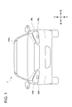
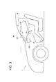
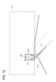
- FIG. 1 is a front view of a vehicle equipped with a vehicle system according to an embodiment of the present invention (hereinafter, simply referred to as the present embodiment). It is a block diagram of the vehicle system concerning this embodiment. It is a figure showing signs that light emitted from HUD (Head-Up @ Display) reaches eyes of a crew member.
- 5 is a flowchart illustrating an example of an operation of the vehicle system according to the first embodiment. It is a figure which shows a mode that a vehicle emits the light pattern which shows a pedestrian crossing on a road surface. It is a figure showing an example of HUD information displayed on a HUD display area. It is a figure showing an example of HUD information displayed on a HUD display field, and a shielding pattern.
- FIG. 4 is a diagram illustrating an example of a light pattern indicating a traveling direction of a vehicle.
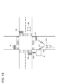
- FIG. 3 is a diagram illustrating a liquid crystal shutter arranged on a front window. It is a flow chart for explaining an example of operation of the vehicle system concerning a 2nd embodiment. It is a figure showing signs that vehicles emit a light pattern which shows a pedestrian's existence position on a road surface. It is a figure (the 1) which shows an example of HUD information and a light pattern in a passenger's view. It is a figure (the 2) showing an example of HUD information and a light pattern in a passenger's view. It is a flow chart for explaining the example of operation of the display system of a 3rd embodiment.
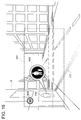
- FIG. 5 is a diagram illustrating an example of HUD information displayed in a HUD display area. It is a figure showing an example of the enlarged image of the pedestrian displayed on the HUD display area. It is a figure showing signs that a vehicle receives information related to a pedestrian from a traffic light installed around the vehicle. It is a figure which shows an example of HUD information which shows the presence of a pedestrian who cannot be visually recognized by a passenger. It is a figure which shows an example of the light pattern which relates a pedestrian visually with the enlarged image of a pedestrian.
- left-right direction is a direction including the “left direction” and the “right direction”.
- the “vertical direction” is a direction including “upward” and “downward”.
- the “front-rear direction” is a direction including the “front direction” and the “back direction”.
- the front-back direction is a direction orthogonal to the left-right direction and the up-down direction.
- FIG. 1 is a front view of a vehicle 1 on which a vehicle system 2 is mounted.
- FIG. 2 is a block diagram of the vehicle system 2.
- the vehicle 1 is a vehicle (automobile) that can run in the automatic driving mode.
- the vehicle system 2 includes a vehicle control unit 3, a vehicle display system 4 (hereinafter, simply referred to as “display system 4”), a sensor 5, a camera 6, and a radar 7. . Further, the vehicle system 2 includes an HMI (Human Machine Interface) 8, a GPS (Global Positioning System) 9, a wireless communication unit 10, a storage device 11, a steering actuator 12, a steering device 13, a brake actuator 14, , A brake device 15, an accelerator actuator 16, and an accelerator device 17.
- HMI Human Machine Interface
- GPS Global Positioning System
- the vehicle control unit 3 is configured to control the traveling of the vehicle 1.
- the vehicle control unit 3 includes, for example, at least one electronic control unit (ECU: Electronic Control Unit).
- the electronic control unit includes a computer system including one or more processors and one or more memories (eg, SoC (System on a Chip)), and an electronic circuit including active elements such as transistors and passive elements.
- the processor includes, for example, at least one of a CPU (Central Processing Unit), an MPU (Micro Processing Unit), a GPU (Graphics Processing Unit), and a TPU (Tensor Processing Unit).
- the CPU may be configured by a plurality of CPU cores.
- the GPU may be configured by a plurality of GPU cores.
- the memory includes a ROM (Read Only Memory) and a RAM (Random Access Memory).
- the vehicle control program may be stored in the ROM.
- the vehicle control program may include an artificial intelligence (AI) program for automatic driving.
- AI is a program (learned model) constructed by supervised or unsupervised machine learning (particularly, deep learning) using a multilayer neural network.
- the RAM may temporarily store a vehicle control program, vehicle control data, and / or surrounding environment information indicating a surrounding environment of the vehicle.
- the processor may be configured to load a program specified from various vehicle control programs stored in the ROM on the RAM and execute various processes in cooperation with the RAM.
- the computer system may be constituted by a non-Neumann computer such as an ASIC (Application Specific Integrated Circuit) or an FPGA (Field-Programmable Gate Array). Further, the computer system may be configured by a combination of a Neumann computer and a non-Neumann computer.
- a non-Neumann computer such as an ASIC (Application Specific Integrated Circuit) or an FPGA (Field-Programmable Gate Array).
- the computer system may be configured by a combination of a Neumann computer and a non-Neumann computer.
- the display system 4 includes a left headlamp 20L, a right headlamp 20R, a left road surface drawing device 45L, and a right road surface drawing device 45R. Further, the display system 4 includes a HUD (Head-Up @ Display) 42 and a display control unit 43.
- HUD Head-Up @ Display
- the left headlamp 20L is arranged on the left front side of the vehicle 1, and irradiates a low beam configured to irradiate a low beam forward of the vehicle 1 and a high beam forward of the vehicle 1. And a high beam lamp configured to perform the operation.
- the right headlamp 20R is arranged on the right front side of the vehicle 1 and is configured to irradiate a low beam to the front of the vehicle 1 and a high beam configured to irradiate a high beam to the front of the vehicle 1. And a lamp.
- Each of the low beam lamp and the high beam lamp has one or more light emitting elements such as an LED (Light Emitting Diode) and an LD (Laser Diode), and optical members such as a lens and a reflector.
- LED Light Emitting Diode
- LD Laser Diode
- optical members such as a lens and a reflector.
- the left head lamp 20L and the right head lamp 20R may be simply referred to as a head lamp 20 for convenience of explanation.
- the left road surface drawing device 45L (an example of a first display device) is disposed in the lamp room of the left headlamp 20L.
- the left road surface drawing device 45L is configured to emit a light pattern toward a road surface outside the vehicle 1.
- the left road surface drawing device 45L includes, for example, a light source unit, a driving mirror, an optical system such as a lens and a mirror, a light source driving circuit, and a mirror driving circuit.
- the light source unit is a laser light source or an LED light source.
- the laser light source is an RGB laser light source configured to emit red laser light, green laser light, and blue laser light, respectively.
- the drive mirror is, for example, a MEMS (Micro Electro Mechanical Systems) mirror, a DMD (Digital Mirror Device), a galvano mirror, a polygon mirror, or the like.
- the light source drive circuit is configured to drive and control the light source unit.
- the light source driving circuit generates a control signal for controlling the operation of the light source unit based on a signal related to the predetermined light pattern transmitted from the display control unit 43, and then transmits the generated control signal to the light source.
- the mirror driving circuit is configured to drive and control the driving mirror.
- the mirror driving circuit generates a control signal for controlling the operation of the driving mirror based on a signal related to the predetermined light pattern transmitted from the display control unit 43, and then drives the generated control signal. It is configured to send to a mirror.
- the left road surface drawing device 45L can draw light patterns of various colors on the road surface by scanning the laser light.
- the light pattern may be an arrow-shaped light pattern indicating the traveling direction of the vehicle 1.
- the right road surface drawing device 45R is disposed in the light room of the right headlamp 20R.
- the right road surface drawing device 45R is configured to emit a light pattern toward a road surface outside the vehicle 1.
- the right road surface drawing device 45R includes a light source unit, a driving mirror, an optical system such as a lens, a light source driving circuit, and a mirror driving circuit.
- the drawing method of the left road surface drawing device 45L and the right road surface drawing device 45R may be a raster scan method, a DLP (Digital Light Processing) method, or an LCOS (Liquid Crystal on silicon) method.
- the light source unit may be an LED light source.
- a projection method may be adopted as a drawing method of the left road surface drawing device 45L and the right road surface drawing device 45R.
- the light source unit may be a plurality of LED light sources arranged in a matrix.
- the left road surface drawing device 45L and the right road surface drawing device 45R may be arranged on the vehicle body roof 100A.
- one road surface drawing device may be arranged on the vehicle body roof 100A.
- the left road surface drawing device 45L and the right road surface drawing device 45R may be simply referred to as the road surface drawing device 45 for convenience of description.
- the road surface drawing device 45 indicates a left road surface drawing device 45L, a right road surface drawing device 45R, or a combination of the left road surface drawing device 45L and the right road surface drawing device 45R.
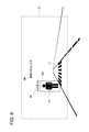
- the HUD 42 (an example of the second display device) is located inside the vehicle 1. Specifically, the HUD 42 is installed at a predetermined location in the room of the vehicle 1. For example, as shown in FIG. 3, the HUD 42 may be arranged in the dashboard of the vehicle 1.
- the HUD 42 functions as a visual interface between the vehicle 1 and the occupant H.
- the HUD 42 displays the HUD information to the occupant H such that predetermined information (hereinafter, referred to as HUD information) is superimposed on a real space outside the vehicle 1 (particularly, a surrounding environment in front of the vehicle 1).
- HUD information predetermined information
- the HUD 42 functions as an AR (Augmented Reality) display.
- the HUD information displayed by the HUD 42 is, for example, vehicle traveling information related to the traveling of the vehicle 1 and / or surrounding environment information related to the surrounding environment of the vehicle 1 (particularly, related to an object existing outside the vehicle 1). Information).
- the HUD 42 has a HUD body 420 and a transparent screen 421.
- the HUD main unit 420 has a light source unit, a driving mirror, an optical system, a light source driving circuit, and a mirror driving circuit.
- the light source unit is, for example, a laser light source or an LED light source.
- the laser light source is, for example, an RGB laser light source configured to emit red laser light, green laser light, and blue laser light, respectively.
- the driving mirror is, for example, a MEMS mirror, a DMD, a galvano mirror, a polygon mirror, or the like.
- the optical system includes at least one of a prism, a lens, a diffuser, and a magnifier.
- the light source drive circuit is configured to drive and control the light source unit.
- the light source driving circuit generates a control signal for controlling the operation of the light source unit based on the image data transmitted from the display control unit 43, and then transmits the generated control signal to the light source unit. It is configured.
- the mirror driving circuit is configured to drive and control the driving mirror.
- the mirror drive circuit generates a control signal for controlling the operation of the drive mirror based on the image data transmitted from the display control unit 43, and then transmits the generated control signal to the drive mirror. It is configured.
- the transparent screen 421 is constituted by a part of the front window 60.
- the transparent screen 421 has a HUD display area D1 capable of displaying HUD information (see FIG. 6).
- the light (image) emitted from the HUD main body 420 is applied to the HUD display area D1 of the transparent screen 421.
- the HUD display area D1 reflects the light emitted from the HUD body 420 toward the occupant H's viewpoint E.
- the occupant H recognizes the light (image) emitted from the HUD main body 420 as a virtual image formed at a predetermined position in front of the transparent screen 421.
- the occupant E can feel as if the HUD information is floating on the road.
- the transparent screen 421 may be configured as a transparent combiner separated from the front window 60. Also in this case, the combiner has a HUD display area. Further, the occupant H recognizes the light (image) emitted from the HUD body 420 as a virtual image formed at a predetermined position in front of the combiner. The position where the virtual image is formed (virtual image formation position) may be changed by adjusting the position of the optical system of the HUD 42 (particularly, the focal length of the projection optical system). At this point, the display control unit 43 can control the HUD 42 based on the position information of the object existing in front of the vehicle 1 so that the position of the object substantially matches the virtual image formation position.
- the drawing method of the HUD 42 may be a raster scan direction, a DLP method, or an LCOS method. When the DLP system or the LCOS system is adopted, the light source unit of the HUD 42 may be an LED light source.
- the display control unit 43 includes a road surface drawing device 45 (specifically, a left road surface drawing device 45L and a right road surface drawing device 45R), a head lamp 20 (specifically, a left head lamp 20L and a right head lamp 20R), and a HUD. Is configured to control the operation. At this point, the display control unit 43 controls the operation of the road surface drawing device 45 (specifically, the left road surface drawing device 45L and the right road surface drawing device 45R) so that a predetermined position on the road surface is irradiated with the light pattern. It is configured to control. Further, the display control unit 43 is configured to control the operation of the HUD 42 so that the HUD information is displayed in the HUD display area D1.
- the display control unit 43 is configured by an electronic control unit (ECU).
- the electronic control unit includes a computer system (eg, SoC, etc.) including one or more processors and one or more memories, and an electronic circuit including active elements such as transistors and passive elements.
- the processor includes at least one of a CPU, an MPU, a GPU, and a TPU.
- the memory includes a ROM and a RAM.
- the computer system may be configured by a non-Neumann computer such as an ASIC or an FPGA.
- the vehicle control unit 3 and the display control unit 43 are provided as separate components, but the vehicle control unit 3 and the display control unit 43 may be integrally configured.
- the display control unit 43 and the vehicle control unit 3 may be configured by a single electronic control unit.
- the display control unit 43 includes two electronic control units, an electronic control unit configured to control the operation of the headlamp 20 and the road surface drawing device 45 and an electronic control unit configured to control the operation of the HUD 42. It may be constituted by a unit.
- the sensor 5 includes at least one of an acceleration sensor, a speed sensor, and a gyro sensor.
- the sensor 5 is configured to detect a traveling state of the vehicle 1 and output traveling state information to the vehicle control unit 3.
- the sensor 5 includes a seating sensor that detects whether the driver is sitting in the driver's seat, a face orientation sensor that detects the direction of the driver's face, an external weather sensor that detects an external weather condition, and whether a person is in the vehicle. It may further include a human sensor or the like for detecting.
- the camera 6 is a camera including an image sensor such as a charge-coupled device (CCD) or a complementary MOS (CMOS).
- the camera 6 includes one or more external cameras 6A and an internal camera 6B.
- the external camera 6 ⁇ / b> A is configured to acquire image data indicating the surrounding environment of the vehicle 1 and transmit the image data to the vehicle control unit 3.
- the vehicle control unit 3 acquires surrounding environment information based on the transmitted image data.
- the surrounding environment information may include information on an object (a pedestrian, another vehicle, a sign, or the like) existing outside the vehicle 1.
- the surrounding environment information may include information on an attribute of an object existing outside the vehicle 1 and information on a distance and a position of the object with respect to the vehicle 1.
- the external camera 6A may be configured as a monocular camera, or may be configured as a stereo camera.
- the internal camera 6B is arranged inside the vehicle 1 and configured to acquire image data indicating the occupant H.
- the internal camera 6B functions as a tracking camera that tracks the viewpoint E of the occupant H.
- the viewpoint E of the occupant H may be either the left eye viewpoint or the right eye viewpoint of the occupant H.
- the viewpoint E may be defined as the midpoint of a line segment connecting the left-eye viewpoint and the right-eye viewpoint.
- the display control unit 43 may specify the position of the viewpoint E of the occupant H based on the image data acquired by the internal camera 6B.
- the position of the viewpoint E of the occupant H may be updated at a predetermined cycle based on the image data, or may be determined only once when the vehicle 1 is started.
- the radar 7 includes at least one of a millimeter-wave radar, a microwave radar, and a laser radar (for example, a LiDAR unit).
- the LiDAR unit is configured to detect a surrounding environment of the vehicle 1.
- the LiDAR unit is configured to acquire 3D mapping data (point cloud data) indicating the surrounding environment of the vehicle 1 and then transmit the 3D mapping data to the vehicle control unit 3.
- the vehicle control unit 3 specifies the surrounding environment information based on the transmitted 3D mapping data.
- the HMI 8 includes an input unit that receives an input operation from a driver, and an output unit that outputs driving information and the like to the driver.
- the input unit includes a steering wheel, an accelerator pedal, a brake pedal, an operation mode switching switch for switching an operation mode of the vehicle 1, and the like.
- the output unit is a display (excluding the HUD) that displays various types of traveling information.
- the GPS 9 is configured to acquire the current position information of the vehicle 1 and output the acquired current position information to the vehicle control unit 3.
- the wireless communication unit 10 receives information (e.g., travel information) related to another vehicle around the vehicle 1 from another vehicle and transmits information (e.g., travel information) related to the vehicle 1 to the other vehicle.
- information e.g., travel information
- the wireless communication unit 10 is configured to receive infrastructure information from infrastructure equipment such as a traffic light and a traffic light, and transmit travel information of the vehicle 1 to the infrastructure equipment (road-vehicle communication).
- the wireless communication unit 10 receives information about the pedestrian from a portable electronic device (a smartphone, a tablet, a wearable device, or the like) carried by the pedestrian, and transmits own-vehicle traveling information of the vehicle 1 to the portable electronic device.
- a portable electronic device a smartphone, a tablet, a wearable device, or the like
- the vehicle 1 may communicate directly with another vehicle, infrastructure equipment, or a portable electronic device in an ad hoc mode, or may communicate with an access point. Further, the vehicle 1 may communicate with another vehicle, infrastructure equipment, or a portable electronic device via a communication network (not shown).
- the communication network includes at least one of the Internet, a local area network (LAN), a wide area network (WAN), and a radio access network (RAN).
- the wireless communication standard is, for example, Wi-Fi (registered trademark), Bluetooth (registered trademark), ZigBee (registered trademark), LPWA, DSRC (registered trademark), or Li-Fi.
- the vehicle 1 may communicate with another vehicle, infrastructure equipment, or a portable electronic device using the fifth generation mobile communication system (5G).
- 5G fifth generation mobile communication system
- the storage device 11 is an external storage device such as a hard disk drive (HDD) or an SSD (Solid State Drive).
- the storage device 11 may store two-dimensional or three-dimensional map information and / or a vehicle control program.
- the three-dimensional map information may be constituted by 3D mapping data (point cloud data).
- the storage device 11 is configured to output map information and a vehicle control program to the vehicle control unit 3 in response to a request from the vehicle control unit 3.
- the map information and the vehicle control program may be updated via the wireless communication unit 10 and the communication network.
- the vehicle control unit 3 When the vehicle 1 runs in the automatic driving mode, the vehicle control unit 3 performs at least one of a steering control signal, an accelerator control signal, and a brake control signal based on driving state information, surrounding environment information, current position information, map information, and the like. Generate one automatically.
- the steering actuator 12 is configured to receive a steering control signal from the vehicle control unit 3 and control the steering device 13 based on the received steering control signal.
- the brake actuator 14 is configured to receive a brake control signal from the vehicle control unit 3 and control the brake device 15 based on the received brake control signal.
- the accelerator actuator 16 is configured to receive an accelerator control signal from the vehicle control unit 3 and control the accelerator device 17 based on the received accelerator control signal.
- the vehicle control unit 3 automatically controls the traveling of the vehicle 1 based on the traveling state information, the surrounding environment information, the current position information, the map information, and the like. That is, in the automatic driving mode, the traveling of the vehicle 1 is automatically controlled by the vehicle system 2.
- the vehicle control unit 3 when the vehicle 1 runs in the manual driving mode, the vehicle control unit 3 generates a steering control signal, an accelerator control signal, and a brake control signal according to a manual operation of the accelerator pedal, the brake pedal, and the steering wheel by the driver.
- the steering control signal, the accelerator control signal, and the brake control signal are generated by the driver's manual operation, so that the driving of the vehicle 1 is controlled by the driver.
- the operation mode includes an automatic operation mode and a manual operation mode.
- the automatic driving mode includes a fully automatic driving mode, an advanced driving support mode, and a driving support mode.
- the vehicle system 2 In the fully automatic driving mode, the vehicle system 2 automatically performs all traveling control of steering control, brake control, and accelerator control, and the driver is not in a state where the vehicle 1 can be driven.
- the vehicle system 2 In the advanced driving support mode, the vehicle system 2 automatically performs all of the driving control such as steering control, brake control, and accelerator control, and the driver does not drive the vehicle 1 although the driver can drive the vehicle 1.
- the vehicle system 2 In the driving support mode, the vehicle system 2 automatically performs a part of the driving control among the steering control, the brake control, and the accelerator control, and the driver drives the vehicle 1 with the driving support of the vehicle system 2.
- the vehicle system 2 In the manual driving mode, the vehicle system 2 does not automatically perform the traveling control, and the driver drives the vehicle 1 without driving assistance of the vehicle system 2.
- the driving mode of the vehicle 1 may be switched by operating a driving mode switch.
- the vehicle control unit 3 changes the driving mode of the vehicle 1 into four driving modes (a fully automatic driving mode, an advanced driving support mode, a driving support mode, and a manual driving mode) according to the driver's operation on the driving mode changeover switch. ) Switch between.
- the driving mode of the vehicle 1 is automatically set based on information on a travelable section in which the automatic driving vehicle can travel, a driving prohibited section in which the driving of the automatic driving vehicle is prohibited, or information on the external weather condition. It may be switched.
- the vehicle control unit 3 switches the operation mode of the vehicle 1 based on the information.
- the driving mode of the vehicle 1 may be automatically switched by using a seating sensor, a face direction sensor, or the like. In this case, the vehicle control unit 3 switches the driving mode of the vehicle 1 based on the output signal from the sitting sensor or the face orientation sensor.
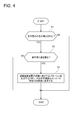
- FIG. 4 is a flowchart for explaining an example of the operation of the vehicle system 2.
- FIG. 5 is a diagram illustrating a state in which the vehicle 1 emits a light pattern L1 indicating a pedestrian crossing onto a road surface around a pedestrian P1 (an example of an object).
- FIG. 6 is a diagram illustrating an example of the HUD information displayed in the HUD display area D1.
- step S1 the vehicle control unit 3 specifies the surrounding environment information indicating the surrounding environment of the vehicle 1 based on the detection data acquired by the external camera 6A and / or the radar 7.
- the process proceeds to step S2.
- the decision result in the step S1 is NO, this processing ends.
- the vehicle control unit 3 When the determination result of step S1 is YES, the vehicle control unit 3 outputs an instruction signal instructing to display information related to the object existing around the vehicle 1 on the HUD 42 and information related to the object. (For example, the attribute information of the object and the position information of the object with respect to the vehicle 1) and viewpoint position information indicating the position of the viewpoint E of the occupant H are transmitted to the display control unit 43.
- the vehicle control unit 3 acquires information related to the target based on detection data such as image data, and acquires viewpoint position information based on the image data acquired by the internal camera 6B.
- the display control unit 43 causes the HUD 42 to display the frame pattern M3 and the object-related information M1 as HUD information in accordance with the received instruction signal (see FIG. 6).
- the frame pattern M3 is a frame pattern surrounding the pedestrian P1 (object).
- the object-related information M1 includes information indicating an attribute of the object and position information of the object with respect to the vehicle 1.
- the object-related information M1 indicates a pedestrian as an attribute of the object and 10 m as position information of the object.
- the occupant H can clearly grasp the existence of the pedestrian P1 by the frame pattern M3, and can grasp information related to the pedestrian P1 by the object-related information M1.
- the display control unit 43 controls the HUD 42 based on the position information of the target object and the viewpoint position information so that the frame pattern M3 is displayed so as to surround the pedestrian P1 in the HUD display area D1. Further, the display control unit 43 controls the HUD 42 based on the received information related to the object so that the object-related information M1 is displayed at a predetermined position in the HUD display area D1. At this point, the object-related information M1 may be displayed in the HUD display area D1 in a state of being visually associated with the frame pattern M3.
- the display control unit 43 may determine the position of the frame pattern M3 based on the position information of the target object without referring to the viewpoint position information. At this point, the display control unit 43 drives and controls the position of the optical system of the HUD 42 (for example, the focal length of the projection optical system) so that the virtual image formation position of the frame pattern M3 substantially matches the position of the pedestrian P1. You may. In such a case, since the virtual image formation position of the frame pattern M3 substantially coincides with the position of the pedestrian P1, even if the viewpoint E of the occupant H moves, the position between the frame pattern M3 and the pedestrian P1 in the field of view of the occupant H is changed. The positional relationship can be maintained. That is, regardless of the position of the viewpoint E, the frame pattern M3 can be displayed in the field of view of the occupant H so as to surround the pedestrian P1.
- the vehicle control unit 3 predicts a future behavior of the detected pedestrian P1, and determines whether to give way to the pedestrian P1 (step S2). .
- the processing ends.
- the vehicle 1 may emit a light pattern L2 indicating the traveling direction of the vehicle 1 on the road surface instead of the light pattern L1.
- the pedestrian P1 can recognize that the vehicle 1 does not stop by looking at the light pattern L2.
- the vehicle control unit 3 determines that the road is yielded to the pedestrian P1 (YES in step S2), the process proceeds to step S3.
- step S3 the road surface drawing device 45 emits the light pattern L1 indicating the pedestrian crossing toward the road surface around the pedestrian P1, and the HUD 42 outputs the vehicle stop message M2 ("the vehicle stops.” )) Is displayed in the HUD area D1 (see FIG. 6).
- the vehicle control unit 3 transmits an instruction signal for instructing emission of the light pattern L1 to a predetermined position in front of the vehicle 1 to the display control unit 43, and displays a vehicle stop message M2 on the HUD 42.
- An instruction signal for instructing the display control section 43 is sent to the display control section 43.
- the display control unit 43 controls the road surface drawing device 45 such that the light pattern L1 is emitted on the road surface in accordance with an instruction signal instructing emission of the light pattern L1. Further, the display control unit 43 causes the HUD 42 to display a vehicle stop message M2.
- rich visual communication between the vehicle 1 and the pedestrian P1 can be realized by the light pattern L1 emitted from the road surface drawing device 45, and the HUD information (object Rich visual communication between the vehicle 1 and the occupant H can be realized by the object-related information M1, the vehicle stop message M2, and the frame pattern M3).
- the light pattern L1 and the vehicle stop message M1 indicate information related to the traveling of the vehicle 1 (specifically, a stop notice of the vehicle 1)
- the information indicated by the light pattern L1 and the vehicle stop message M1 are Are associated with each other. Therefore, the pedestrian P1 can clearly grasp the stop of the vehicle 1 by looking at the light pattern L1 emitted from the road surface drawing device 45.
- the occupant H can clearly grasp the stop of the vehicle 1 by looking at the vehicle stop message M2 displayed by the HUD 42.
- the object-related information M1 and the frame pattern M3 are displayed as HUD information on the HUD 42, the occupant H can clearly grasp the presence of the pedestrian P1 by the frame pattern M3, and can also detect the object-related information M1. Thereby, information related to the pedestrian P1 can be clearly grasped.
- predetermined graphic information may be displayed on the HUD 42 as HUD information indicating the stop of the vehicle 1.
- the display control unit 43 may display graphic information indicating a pedestrian crossing on the HUD 42 as HUD information.
- the graphic information indicating the pedestrian crossing may be displayed on the HUD 42 (HUD display area D1) so as to overlap the light pattern L1 as viewed from the occupant H.
- the display color of the graphic information indicating the pedestrian crossing may be different from the display color of the light pattern L1.
- the display control unit 43 may display a shielding pattern M4 for hiding the light pattern L1 on the HUD 42 as HUD information.
- the shielding pattern M4 may be displayed on the HUD 42 so as to overlap with the light pattern L1 when viewed from the occupant H.
- the display color of the shielding pattern M4 may be the same as the background color of the real space in front of the vehicle 1.
- the display color of the shielding pattern M4 may be the same as the color of the road surface (for example, gray). In this manner, the occupant H can be prevented from visually recognizing the light pattern L1 by the shielding pattern M4 having the same display color as the background color of the real space. Therefore, it is possible to prevent a misunderstanding from occurring in the visual communication between the occupant H and the vehicle 1 due to the light pattern L1 presented to the pedestrian P1.
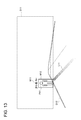
- FIG. 9 is a diagram illustrating the liquid crystal shutter 63 arranged on the front window 60.
- the HUD 42A has a HUD main body 420, a transparent screen 421, and a liquid crystal shutter 63.
- the liquid crystal shutter 63 is arranged to face the transparent screen 421 (more specifically, the HUD display area D1) formed by a part of the front window 60.
- the liquid crystal shutter 63 functions as a transmittance adjusting unit that can adjust the transmittance of light passing through the liquid crystal shutter 63.
- the liquid crystal shutter 63 has, for example, two polarizing filters and a liquid crystal layer provided between the two polarizing filters.
- One of the two polarizing filters is configured to pass light polarized in a predetermined direction, while the other of the two polarizing filters passes light polarized in a direction perpendicular to the predetermined direction. You may be comprised so that it may make it.
- the display control unit 43 can reduce the transmittance of the liquid crystal shutter 63 by adjusting the voltage applied to the liquid crystal layer. As described above, by reducing the transmittance of the liquid crystal shutter 63, the occupant H can be prevented from visually recognizing the reflected light of the light pattern applied to the road surface.
- the occupant H can clearly see the light (HUD information) emitted from the HUD main body 420.
- the liquid crystal shutter 63 it is possible to prevent a misunderstanding from occurring in the communication between the occupant H and the vehicle 1 due to the light pattern presented to the pedestrian P1.
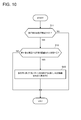
- FIG. 10 is a flowchart for explaining an example of the operation of the vehicle system 2.
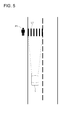
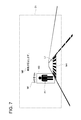
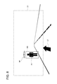
- FIG. 11 is a diagram illustrating a state in which the vehicle 1 emits a light pattern L11 indicating the location of the pedestrian P11 onto the road surface toward the pedestrian P11 (an example of an object).
- FIG. 12 is a diagram showing HUD information (specifically, object-related information M11 and frame pattern M12) and a light pattern L11 in the field of view of the occupant H.
- step S11 the vehicle control unit 3 specifies the surrounding environment information indicating the surrounding environment of the vehicle 1 based on the detection data acquired by the external camera 6A and / or the radar 7.
- step S11 the vehicle control unit 3 specifies the presence of the pedestrian P11 based on the surrounding environment information (YES in step S11)
- the vehicle control unit 3 determines whether the pedestrian P11 exists within a predetermined distance from the vehicle 1. A determination is made (step S12). On the other hand, if the decision result in the step S11 is NO, the present process ends.
- the vehicle control unit 3 instructs the HUD information to be displayed on the HUD 42 in step S13.
- a first instruction signal and a second instruction signal for instructing the pedestrian P11 to emit the light pattern L11 are transmitted to the display control unit 43.
- the vehicle control unit 3 determines information related to the object (for example, attribute information of the object and position information of the object with respect to the vehicle 1) and viewpoint position information indicating the position of the viewpoint E of the occupant H. Is transmitted to the display control unit 43.
- the vehicle control unit 3 acquires information related to the target based on detection data such as image data, and acquires viewpoint position information based on the image data acquired by the internal camera 6B.
- the display control unit 43 causes the HUD 42 to display the object-related information M11 and the frame pattern M12 as HUD information according to the received first instruction signal (see FIG. 12).
- the object-related information M11 includes information indicating an attribute of the object and position information of the object with respect to the vehicle 1.
- the object-related information M11 indicates a pedestrian as an attribute of the object and 26 m as position information of the object.
- the frame pattern M12 is a frame pattern surrounding the pedestrian P11 (object).
- the occupant H can clearly grasp the presence of the pedestrian P11 by looking at the frame pattern M12, and also can grasp information related to the pedestrian P11 by the object related information M11.
- the display control unit 43 controls the HUD 42 based on the position information of the target object and the viewpoint position information so that the frame pattern M12 is displayed so as to surround the pedestrian P11 in the HUD display area D11. Further, the display control unit 43 controls the HUD 42 based on the received information related to the target so that the target related information M11 is displayed at a predetermined position in the HUD display area D11. At this point, the object-related information M11 may be displayed in the HUD display area D11 while being visually associated with the frame pattern M12.
- the display control unit 43 may determine the position of the frame pattern M12 based on the position information of the target object without referring to the viewpoint position information. At this point, the display control unit 43 determines the position of the optical system of the HUD 42 (for example, the focus of the projection optical system included in the HUD main unit 420) such that the virtual image formation position of the frame pattern M12 substantially matches the position of the pedestrian P11. Distance, etc.). In such a case, since the virtual image formation position of the frame pattern M12 substantially coincides with the position of the pedestrian P11, even if the viewpoint E of the occupant H moves, the position between the frame pattern M12 and the pedestrian P11 in the field of view of the occupant H moves. The positional relationship can be maintained. That is, the frame pattern M12 can be displayed in the field of view of the occupant H so as to surround the pedestrian P11 without depending on the position of the viewpoint E.
- step S13 the display control unit 43 controls the road surface drawing device 45 such that the road surface drawing device 45 emits the light pattern L11 on the road surface toward the pedestrian P11 in response to the received second instruction signal.
- the shape of the light pattern L11 is not limited to a linear shape, but may be an arbitrary shape such as a triangular shape or an arrow shape.
- a HUD display area D11 capable of displaying HUD information is a light pattern area D12 (an example of a second area) in which a light pattern emitted on a road surface can exist.
- the HUD display area D11 is set so as to be higher than the above.
- the field of view of the occupant H is the field of view of the occupant H from the viewpoint E.
- the HUD display area D11 is located above the light pattern area D12 so as not to overlap with the light pattern area D12 within the field of view of the occupant H.
- the light pattern area D12 includes a road surface that is within a distance d (an example of a first distance) from the tip of the vehicle 1, while the HUD display area D11 includes a road surface that exceeds the distance d from the tip of the vehicle 1. . See FIG. 11 for the distance d.
- the distance d is 30 m
- the light pattern area D12 includes a road surface within 30 m from the tip of the vehicle 1
- the HUD display area D11 includes a road surface exceeding 30 m from the tip of the vehicle 1.
- the display system 4 when the display system 4 emits the light pattern L11 on the road surface and displays the HUD information on the HUD 42 (HUD display area D11), the HUD display area in the field of view of the occupant H
- the HUD display area D11 is set so that D11 is located above the light pattern area D12. Therefore, the HUD information and the light pattern L11 can be visually recognized by the occupant H in a state where they are clearly distinguished from each other.
- the display system 4 capable of improving the visibility of the occupant H with respect to the light pattern L11 and the HUD information emitted on the road surface.
- the light pattern region D12 shown in FIG. 11 includes only the road surface of the road, but the light pattern region D12 may include not only the road surface of the road but also the road surface of the sidewalk.
- the light pattern L11 may extend from a predetermined position on the road surface of the road to near the vicinity of the foot of the pedestrian P11.
- FIG. 13 is a diagram showing HUD information (object-related information M11, frame pattern M12) and a light pattern L11 in the field of view of the occupant H.
- This modification differs from the HUD display area D11 shown in FIG. 12 in that the HUD display area D11 partially overlaps with the light pattern area D12 and the frame pattern M12 surrounds the whole body of the pedestrian P11.
- the light pattern area D12 includes a road surface within a distance d from the tip of the vehicle 1
- the HUD display area D11 includes a road surface that exceeds a distance d2 (an example of a second distance) from the tip of the vehicle 1. .
- the distance d2 is smaller than the distance d.
- the distance d2 is 25 m.
- the light pattern region D12 includes a road surface within 30 m from the front end of the vehicle 1, while the HUD display region D11 includes a road surface exceeding 25 m from the front end of the vehicle 1.
- the HUD display area D11 partially overlaps with the light pattern area D12, and the HUD display area D11 is set so as to be located above the light pattern area D12 in the field of view of the occupant H.
- the information and the light pattern can be visually recognized by the occupant while being distinguished from each other.
- the visibility of the occupant H with respect to the light pattern L11 and the HUD information can be improved.
- the light pattern L11 and the frame pattern M12 can be visually associated with each other (in other words, the light pattern L11 and the frame pattern M12 are connected to each other when viewed from the occupant H).
- the occupant H can clearly grasp the existence of the pedestrian P11 by looking at the light pattern L11, and can clearly grasp the information related to the pedestrian P11 by looking at the HUD information. .
- the occupant H can simultaneously grasp the location of the pedestrian P11 and information related to the pedestrian P11.
- FIG. 14 is a flowchart for explaining an operation example of the display system 4.
- FIG. 15 is a diagram illustrating a state in which the vehicle 1 emits the light pattern L21 toward a pedestrian P21 (an example of an object) existing around the vehicle 1.
- FIG. 16 is a diagram illustrating an example of the HUD information displayed in the HUD display area D21. In particular, FIG. 16 shows HUD information M21 to M24 in the field of view of the occupant H and the light pattern L21 emitted on the road surface.
- step S21 the vehicle control unit 3 specifies the surrounding environment information indicating the surrounding environment of the vehicle 1 based on the detection data acquired by the external camera 6A and / or the radar 7.
- the vehicle control unit 3 determines whether the pedestrian P21 exists within a predetermined distance from the vehicle 1. A determination is made (step S22). On the other hand, if the decision result in the step S21 is NO, this processing ends.
- the vehicle control unit 3 instructs the HUD information to be displayed on the HUD 42 in step S23.
- a first instruction signal and a second instruction signal for instructing the pedestrian P21 to emit the light pattern L21 are transmitted to the display control unit 43.
- the vehicle control unit 3 determines information related to the object (in this example, the pedestrian P21) (for example, the attribute information of the object, the position information of the object with respect to the vehicle 1, and the future of the object). (Information related to the action) to the display control unit 43.
- the vehicle control unit 3 acquires information related to the target object based on detection data such as image data and 3D mapping data.
- the display control unit 43 causes the HUD 42 to display the HUD information M21 to M23 according to the received first instruction signal (see FIG. 16).
- the HUD information M21 includes the attribute information of the target and the position information of the target with respect to the vehicle 1.
- the HUD information M21 indicates a pedestrian as the attribute information of the target and 26 m as the position information of the target.
- the HUD information M22 includes information related to the behavior prediction of the target object. As shown in FIG. 16, the HUD information M22 indicates that the pedestrian P21 is going to cross the pedestrian crossing C as behavior prediction information of the pedestrian P21.
- the HUD information M23 includes information indicating the presence of the target. As shown in FIG. 16, the HUD information M23 indicates a pedestrian mark as information indicating the presence of the pedestrian P21. Note that the HUD information M23 may include text information such as "there is a pedestrian" and graphic information such as an exclamation mark as information indicating the presence of the target object.
- the HUD information M24 includes speed limit information of a road on which the vehicle 1 is traveling. As shown in FIG. 16, the HUD information M24 indicates a speed limit of 60 km / h. Note that the HUD information M24 may be displayed in the HUD display area D21 irrespective of whether or not the presence of the target is detected.
- the display control unit 43 controls the road surface drawing device 45 such that the road surface drawing device 45 emits the light pattern L21 onto the road surface toward the pedestrian P21 according to the received second instruction signal.
- the light pattern L21 is a linear light pattern extending from the vehicle 1 toward the pedestrian P21.
- the light pattern L21 can visually associate the vehicle 1 with the pedestrian P21.
- the occupant H of the vehicle 1 can clearly grasp the presence of the pedestrian P21 by visually recognizing the light pattern L21.
- the shape of the light pattern L21 is not limited to a linear shape, but may be an arbitrary shape such as a triangular shape or an arrow shape.
- the right road surface drawing device 45R mounted on the right headlamp 20R emits the light pattern L21 toward the pedestrian P21. Is also good.
- the left road surface drawing device 45L mounted on the left headlamp 20L may emit the light pattern L21 toward the pedestrian P21. In this case, since the inclination angle of the light pattern L21 with respect to the traveling direction of the vehicle increases, the visibility of the light pattern L21 can be improved.
- the road surface drawing device 45 emits the light pattern L21 toward the pedestrian P21, and the HUD 42 walks.
- the HUD information M21 to M23 related to the person P21 is displayed in the HUD display area D21. Therefore, the occupant H of the vehicle 1 can grasp the position of the pedestrian P21 by looking at the light pattern L21 emitted from the road surface drawing device 45, and grasps information related to the pedestrian P21 through the HUD. be able to.
- the position of the pedestrian P21 and the information related to the pedestrian P21 are visually presented to the occupant H by using the two different display devices, the road surface drawing device 45 and the HUD 42, so that the occupant H becomes the pedestrian P21.
- the occupant H can see the HUD information M22 and thereby determine the pedestrian P21.
- the appropriate running control of the vehicle 1 in consideration of the future behavior of the vehicle 1 can be performed. For example, the occupant H can determine to stop the vehicle 1 in front of the pedestrian crossing C through the HUD information M22 indicating that the vehicle 1 is going to cross the pedestrian crossing C.
- HUD information M25 indicating an enlarged image of the pedestrian P21 may be displayed in the HUD display area D21.
- the display control unit 43 acquires image data indicating the surrounding environment of the vehicle 1 captured by the external camera 6A from the vehicle control unit 3, and then generates an enlarged image of the pedestrian P21 based on the image data.
- the HUD 42 is controlled so that the indicated HUD information M25 is displayed in the HUD display area D21.
- the presence of an object such as a pedestrian is detected based on detection data (for example, image data) acquired from an on-vehicle sensor such as the external camera 6A.
- the presence of the target object may be detected through communication.
- the vehicle 1 may receive information related to the pedestrian P22 from at least one of the traffic signals S1 to S4 (an example of an external communication device) existing around the vehicle 1.
- the vehicle 1 may receive information related to the pedestrian P22 from another vehicle 1B (an example of an external communication device) existing around the vehicle 1.
- the traffic signals S1 to S4 and the other vehicle 1B include a camera configured to acquire image data indicating a surrounding environment, and a wireless communication unit.
- the traffic light S1 which is an example of the traffic infrastructure, acquires information related to the pedestrian P22 based on the image data acquired by the camera.
- the information related to the pedestrian P22 may include at least one of position information of the pedestrian P22, attribute information of the pedestrian P22, and behavior prediction information of the pedestrian P22.
- the traffic light S1 broadcasts information related to the pedestrian P22 to the outside through the wireless communication unit.
- the vehicle control unit 3 of the vehicle 1 receives information related to the pedestrian P22 from the traffic light S1 through the wireless communication unit 10.
- the display control unit 43 controls the road surface drawing device 45 so that the light pattern L21 is emitted toward the pedestrian P22 based on the information related to the pedestrian P22, and indicates the presence of the pedestrian P22.
- the HUD information M26 is displayed on the HUD 42 (see FIG. 19). As shown in FIG. 19, the occupant H can grasp the position of the pedestrian P22 hidden behind the building B by looking at the light pattern L21 and the HUD information M26.
- the in-vehicle sensor such as a camera mounted on the vehicle 1 and / or the occupant H cannot detect the pedestrian P22 (that is, in a situation where the pedestrian P22 exists in a place that cannot be seen from the vehicle 1)
- the vehicle 1 can acquire information related to the pedestrian P22 through the road-to-vehicle communication or the vehicle-to-vehicle communication, and the occupant H of the vehicle 1 determines the presence of the pedestrian P22 through the road surface drawing device 45 and the HUD 42. It can be clearly understood.
- the light pattern L21 emitted toward the pedestrian P21 has been described as a light pattern that visually associates the vehicle 1 with the pedestrian P21.
- the light pattern of the present embodiment is not limited to this. Not something.
- the light pattern emitted from the road surface drawing device 45 may be a light pattern L22 that visually associates the pedestrian P21 with the HUD information M25 indicating an enlarged image of the pedestrian P21.
- the HUD information M25 may be displayed below the HUD display area D2.
- the display control unit 43 may determine the emission position of the light pattern L22 so that the pedestrian P21 and the HUD information M25 are visually related by the light pattern L22.
- the display control unit 43 may determine the display position of the HUD information M25 such that the light pattern L22 visually associates the pedestrian P21 with the HUD information M25 after determining the emission position of the light pattern L22. Good.
- the driving mode of the vehicle has been described as including the fully automatic driving mode, the advanced driving support mode, the driving support mode, and the manual driving mode. Should not be limited to.
- the classification of the driving mode of the vehicle may be changed as appropriate in accordance with the laws and regulations regarding automatic driving in each country.
- the definitions of “fully automatic driving mode”, “advanced driving assistance mode”, and “driving assistance mode” described in the description of the present embodiment are merely examples, and laws and regulations relating to automatic driving in each country or These definitions may be changed as appropriate according to the rules.
Landscapes
- Engineering & Computer Science (AREA)
- Mechanical Engineering (AREA)
- Transportation (AREA)
- Combustion & Propulsion (AREA)
- Chemical & Material Sciences (AREA)
- Physics & Mathematics (AREA)
- General Physics & Mathematics (AREA)
- Automation & Control Theory (AREA)
- Human Computer Interaction (AREA)
- Optics & Photonics (AREA)
- Instrument Panels (AREA)
- Traffic Control Systems (AREA)
- Fittings On The Vehicle Exterior For Carrying Loads, And Devices For Holding Or Mounting Articles (AREA)
- Arrangement Of Elements, Cooling, Sealing, Or The Like Of Lighting Devices (AREA)
- Lighting Device Outwards From Vehicle And Optical Signal (AREA)
Abstract
Description
前記車両の外部の路面に向けて光パターンを出射するように構成された第1表示装置と、
前記車両の内部に位置すると共に、所定の情報が前記車両の外部の現実空間と重畳されるように前記所定の情報を前記車両の乗員に向けて表示するように構成された第2表示装置と、を備える。
前記車両の外部の路面に向けて光パターンを出射するように構成された第1表示装置と、
前記車両の内部に位置すると共に、所定の情報が前記車両の外部の現実空間と重畳されるように前記所定の情報を前記車両の乗員に向けて表示するように構成された第2表示装置と、を備える。
前記乗員の視界において、前記所定の情報が表示可能な第1領域は、前記路面上に出射された光パターンが存在可能な第2領域よりも上方に位置するように、前記第1領域が設定されている。
前記車両の外部の路面に向けて光パターンを出射するように構成された第1表示装置と、
前記車両の内部に位置すると共に、所定の情報が前記車両の外部の現実空間と重畳されるように前記所定の情報を前記車両の乗員に向けて表示するように構成された第2表示装置と、を備える。
前記第1表示装置は、対象物に向けて前記光パターンを出射すると共に、前記第2表示装置は、前記対象物に関連する情報を前記乗員に向けて表示する。
次に、図4から図6を参照して第1実施形態に係る車両システム2の動作の一例について以下に説明する。図4は、車両システム2の動作の一例を説明するためのフローチャートである。図5は、車両1が横断歩道を示す光パターンL1を歩行者P1(対象物の一例)の周辺の路面上に出射する様子を示す図である。図6は、HUD表示領域D1に表示されるHUD情報の一例を示す図である。
次に、図10から図12を参照して第2実施形態に係る車両システム2の動作の一例について以下に説明する。図10は、車両システム2の動作の一例を説明するためのフローチャートである。図11は、車両1が歩行者P11の存在位置を示す光パターンL11を歩行者P11(対象物の一例)に向けて路面上に出射する様子を示す図である。図12は、乗員Hの視界におけるHUD情報(具体的には、対象物関連情報M11、枠パターンM12)と光パターンL11を示す図である。
次に、図13を参照してHUD表示領域D11の変形例について以下に説明する。図13は、乗員Hの視界におけるHUD情報(対象物関連情報M11、枠パターンM12)と光パターンL11を示す図である。本変形例では、HUD表示領域D11が光パターン領域D12と部分的に重複すると共に、枠パターンM12が歩行者P11の全身を囲む点で図12に示すHUD表示領域D11とは相違する。この点において、光パターン領域D12は、車両1の先端から距離d以内の路面を含む一方、HUD表示領域D11は、車両1の先端から距離d2(第2距離の一例)を超えた路面を含む。ここで、距離d2は距離dよりも小さい。例えば、距離dが30mである場合に、距離d2は25mである。この場合、光パターン領域D12は、車両1の先端から30m以内の路面を含む一方、HUD表示領域D11は、車両1の先端から25mを超えた路面を含む。
次に、図14から図16を主に参照することで第3実施形態の表示システム4の動作例について以下に説明する。図14は、表示システム4の動作例を説明するためのフローチャートである。図15は、車両1が車両1の周辺に存在する歩行者P21(対象物の一例)に向けて光パターンL21を出射する様子を示す図である。図16は、HUD表示領域D21に表示されるHUD情報の一例を示す図である。特に、図16では、乗員Hの視界におけるHUD情報M21~M24と路面上に出射された光パターンL21が示される。
Claims (20)
- 車両に設けられた車両用表示システムであって、
前記車両の外部の路面に向けて光パターンを出射するように構成された第1表示装置と、
前記車両の内部に位置すると共に、所定の情報が前記車両の外部の現実空間と重畳されるように前記所定の情報を前記車両の乗員に向けて表示するように構成された第2表示装置と、を備えた車両用表示システム。 - 前記光パターンが示す情報と前記所定の情報は互いに関連付けられている、請求項1に記載の車両用表示システム。
- 前記光パターン及び前記所定の情報は、前記車両の走行に関連した情報を示す、請求項2に記載の車両用表示システム。
- 前記光パターンは、前記車両の走行に関連した情報を示す一方、前記所定の情報は、前記車両の周辺に存在する対象物に関連した情報を示す、請求項1に記載の車両用表示システム。
- 前記所定の情報は、前記乗員から見て前記光パターンと重なるように表示され、
前記所定の情報の表示色は、前記光パターンの表示色とは異なる、
請求項1から3のうちいずれか一項に記載の車両用表示システム。 - 前記第2表示装置は、前記乗員から見て前記光パターンと重なるように前記現実空間の背景色と同一の表示色を有する遮蔽パターンを表示するように構成されている、請求項1から3のうちいずれか一項に記載の車両用表示システム。
- 前記第2表示装置は、前記所定の情報が表示される表示領域に対向するように配置された透過率調整部を有する、請求項1から6のうちいずれか一項に記載の車両用表示システム。
- 車両に設けられた車両用表示システムであって、
前記車両の外部の路面に向けて光パターンを出射するように構成された第1表示装置と、
前記車両の内部に位置すると共に、所定の情報が前記車両の外部の現実空間と重畳されるように前記所定の情報を前記車両の乗員に向けて表示するように構成された第2表示装置と、を備え、
前記乗員の視界において、前記所定の情報が表示可能な第1領域は、前記路面上に出射された光パターンが存在可能な第2領域よりも上方に位置するように、前記第1領域が設定されている、車両用表示システム。 - 前記第1領域は、前記第2領域と重複しないように前記第2領域の上方に位置する、
請求項8に記載の車両用表示システム。 - 前記第2領域は、前記車両の先端から第1距離以内の路面を含む一方で、前記第1領域は、前記車両の先端から前記第1距離を超えた路面を含む、請求項9に記載の車両用表示システム。
- 前記第1領域は、前記第2領域と部分的に重複するように前記第2領域の上方に位置する、請求項8に記載の車両用表示システム。
- 前記第2領域は、前記車両の先端から第1距離以内の路面を含む一方で、前記第1領域は、前記車両の先端から第2距離を超えた路面を含み、
前記第2距離は、前記第1距離よりも小さい、
請求項11に記載の車両用表示システム。 - 前記光パターンは、前記車両の周辺に存在する対象物に向けて前記路面上に出射され、
前記所定の情報は、前記対象物に関連した情報を示す、
請求項8から12のうちのいずれか一項に記載の車両用表示システム。 - 車両に設けられた車両用表示システムであって、
前記車両の外部の路面に向けて光パターンを出射するように構成された第1表示装置と、
前記車両の内部に位置すると共に、所定の情報が前記車両の外部の現実空間と重畳されるように前記所定の情報を前記車両の乗員に向けて表示するように構成された第2表示装置と、を備え、
前記第1表示装置は、対象物に向けて前記光パターンを出射すると共に、前記第2表示装置は、前記対象物に関連する情報を前記乗員に向けて表示する、車両用表示システム。 - 前記車両から所定の距離以内に前記対象物が存在する場合に、前記第1表示装置は、前記対象物に向けて前記光パターンを出射すると共に、前記第2表示装置は、前記対象物に関連する情報を前記乗員に向けて表示する、請求項14に記載の車両用表示システム。
- 前記対象物に関連する情報は、前記対象物の存在を示す情報を含む、請求項14又は15に記載の車両用表示システム。
- 前記対象物に関連する情報は、前記対象物の拡大画像を含む、請求項14から16のうちいずれか一項に記載の車両用表示システム。
- 前記対象物に関連する情報は、前記対象物の将来行動に関連する情報を含む、請求項14から17のうちいずれか一項に記載の車両用表示システム。
- 請求項14から18のうちいずれか一項に記載の車両用表示システムと、
前記車両の外部に存在する外部通信機器から前記対象物の存在を示す情報を受信するように構成された無線通信部と、を備えた車両システム。 - 請求項1から18のうちいずれか一項に記載の車両用表示システムを備えた車両。
Priority Applications (3)
| Application Number | Priority Date | Filing Date | Title |
|---|---|---|---|
| US17/266,820 US12083957B2 (en) | 2018-08-06 | 2019-08-02 | Vehicle display system and vehicle |
| EP19847682.2A EP3835128A4 (en) | 2018-08-06 | 2019-08-02 | VEHICLE AND VEHICLE DISPLAY SYSTEM |
| JP2020535736A JP7295863B2 (ja) | 2018-08-06 | 2019-08-02 | 車両用表示システム及び車両 |
Applications Claiming Priority (6)
| Application Number | Priority Date | Filing Date | Title |
|---|---|---|---|
| JP2018-147733 | 2018-08-06 | ||
| JP2018-147736 | 2018-08-06 | ||
| JP2018147733 | 2018-08-06 | ||
| JP2018147736 | 2018-08-06 | ||
| JP2018-152901 | 2018-08-15 | ||
| JP2018152901 | 2018-08-15 |
Publications (1)
| Publication Number | Publication Date |
|---|---|
| WO2020031912A1 true WO2020031912A1 (ja) | 2020-02-13 |
Family
ID=69413572
Family Applications (1)
| Application Number | Title | Priority Date | Filing Date |
|---|---|---|---|
| PCT/JP2019/030570 Ceased WO2020031912A1 (ja) | 2018-08-06 | 2019-08-02 | 車両用表示システム及び車両 |
Country Status (5)
| Country | Link |
|---|---|
| US (1) | US12083957B2 (ja) |
| EP (1) | EP3835128A4 (ja) |
| JP (1) | JP7295863B2 (ja) |
| CN (1) | CN110803106A (ja) |
| WO (1) | WO2020031912A1 (ja) |
Cited By (2)
| Publication number | Priority date | Publication date | Assignee | Title |
|---|---|---|---|---|
| DE102024102623A1 (de) | 2023-02-13 | 2024-08-14 | Toyota Jidosha Kabushiki Kaisha | Informationsverarbeitungsvorrichtung, informationsverarbeitungsverfahren und nicht-transistorisches speichermedium |
| US12409847B2 (en) | 2023-02-13 | 2025-09-09 | Toyota Jidosha Kabushiki Kaisha | Information processing device |
Families Citing this family (10)
| Publication number | Priority date | Publication date | Assignee | Title |
|---|---|---|---|---|
| EP3858668B1 (en) * | 2018-09-28 | 2024-03-20 | Koito Manufacturing Co., Ltd. | Lamp system |
| KR102619558B1 (ko) * | 2018-11-16 | 2024-01-02 | 현대모비스 주식회사 | 자율주행차의 제어시스템 및 그 제어방법 |
| JP2021092979A (ja) * | 2019-12-10 | 2021-06-17 | 本田技研工業株式会社 | 自動運転車用情報提示装置 |
| DE102020205444B3 (de) * | 2020-04-29 | 2021-07-08 | Continental Automotive Gmbh | Gerät zum Generieren eines virtuellen Bildes mit Störlichtunterdrückung, Head-Up-Display aufweisend ein solches Gerät und Fahrzeug aufweisend ein solches Gerät bzw. Head-Up-Display |
| JP2023021484A (ja) | 2021-08-02 | 2023-02-14 | 株式会社小糸製作所 | 車両の表示装置 |
| KR20230023330A (ko) * | 2021-08-10 | 2023-02-17 | 현대모비스 주식회사 | 차량의 표시 장치 및 그것의 동작 방법, 차량 |
| JP7442948B2 (ja) * | 2021-10-18 | 2024-03-05 | 矢崎総業株式会社 | 車外表示装置 |
| KR20230168859A (ko) * | 2022-06-08 | 2023-12-15 | 현대모비스 주식회사 | 자동차 조명 장치 및 그 작동 방법 |
| JP7841985B2 (ja) * | 2022-08-15 | 2026-04-07 | トヨタ自動車株式会社 | 車両用表示装置 |
| JP2024132428A (ja) * | 2023-03-17 | 2024-10-01 | 本田技研工業株式会社 | 車両用照明装置及び照明装置 |
Citations (7)
| Publication number | Priority date | Publication date | Assignee | Title |
|---|---|---|---|---|
| JPH09277887A (ja) | 1996-04-16 | 1997-10-28 | Honda Motor Co Ltd | 自動追従走行システム |
| JP2016055691A (ja) * | 2014-09-08 | 2016-04-21 | 株式会社小糸製作所 | 車両用表示システム |
| JP2016088187A (ja) * | 2014-10-31 | 2016-05-23 | 三菱電機株式会社 | 車両用透過表示装置 |
| JP2018014616A (ja) * | 2016-07-21 | 2018-01-25 | 株式会社Jvcケンウッド | 表示制御装置、方法、プログラム及び表示制御システム |
| JP2018147733A (ja) | 2017-03-06 | 2018-09-20 | Necプラットフォームズ株式会社 | コネクタ及びコネクタセット |
| JP2018147736A (ja) | 2017-03-06 | 2018-09-20 | 東京瓦斯株式会社 | 燃料電池システム |
| JP2018152901A (ja) | 2011-09-16 | 2018-09-27 | エレクトロニクス アンド テレコミュニケーションズ リサーチ インスチチュートElectronics And Telecommunications Research Institute | 予測動きベクトル誘導方法及びその方法を使用する装置 |
Family Cites Families (10)
| Publication number | Priority date | Publication date | Assignee | Title |
|---|---|---|---|---|
| JP4995748B2 (ja) | 2008-01-29 | 2012-08-08 | 株式会社小糸製作所 | 車両用前照灯装置及び車両用前照灯装置の制御方法 |
| US10703299B2 (en) * | 2010-04-19 | 2020-07-07 | SMR Patents S.à.r.l. | Rear view mirror simulation |
| DE102012023630B4 (de) | 2012-12-03 | 2025-03-13 | Volkswagen Aktiengesellschaft | Verfahren zur Information eines Fahrzeugführers hinsichtlich eines von einem auf Umgebungsdaten basierten Fahrerassistenzsystems eines Fahrzeugs ausgeführten automatischen Fahrmanövers |
| JP5790698B2 (ja) * | 2013-04-11 | 2015-10-07 | トヨタ自動車株式会社 | 情報表示装置、及び情報表示方法 |
| AU2015238339B2 (en) * | 2014-03-25 | 2018-02-22 | Jaguar Land Rover Limited | Navigation system |
| EP3150443B1 (en) * | 2014-07-01 | 2019-08-21 | Nissan Motor Co., Ltd | Display device for vehicle and display method for vehicle |
| DE102014226188B4 (de) | 2014-12-17 | 2026-03-26 | Bayerische Motoren Werke Aktiengesellschaft | Kommunikation zwischen einem Fahrzeug und einem Verkehrsteilnehmer im Umfeld des Fahrzeugs |
| US10248196B2 (en) * | 2016-08-23 | 2019-04-02 | Toyota Jidosha Kabushiki Kaisha | System for occlusion adjustment for in-vehicle augmented reality systems |
| KR102037324B1 (ko) * | 2017-11-30 | 2019-10-28 | 엘지전자 주식회사 | 자율주행 차량 및 그 제어 방법 |
| CN108237973B (zh) * | 2017-12-19 | 2020-12-29 | 深圳市海梁科技有限公司 | 一种标识系统及无人驾驶车辆 |
-
2019
- 2019-08-02 EP EP19847682.2A patent/EP3835128A4/en not_active Withdrawn
- 2019-08-02 WO PCT/JP2019/030570 patent/WO2020031912A1/ja not_active Ceased
- 2019-08-02 US US17/266,820 patent/US12083957B2/en active Active
- 2019-08-02 JP JP2020535736A patent/JP7295863B2/ja active Active
- 2019-08-06 CN CN201910722339.5A patent/CN110803106A/zh active Pending
Patent Citations (7)
| Publication number | Priority date | Publication date | Assignee | Title |
|---|---|---|---|---|
| JPH09277887A (ja) | 1996-04-16 | 1997-10-28 | Honda Motor Co Ltd | 自動追従走行システム |
| JP2018152901A (ja) | 2011-09-16 | 2018-09-27 | エレクトロニクス アンド テレコミュニケーションズ リサーチ インスチチュートElectronics And Telecommunications Research Institute | 予測動きベクトル誘導方法及びその方法を使用する装置 |
| JP2016055691A (ja) * | 2014-09-08 | 2016-04-21 | 株式会社小糸製作所 | 車両用表示システム |
| JP2016088187A (ja) * | 2014-10-31 | 2016-05-23 | 三菱電機株式会社 | 車両用透過表示装置 |
| JP2018014616A (ja) * | 2016-07-21 | 2018-01-25 | 株式会社Jvcケンウッド | 表示制御装置、方法、プログラム及び表示制御システム |
| JP2018147733A (ja) | 2017-03-06 | 2018-09-20 | Necプラットフォームズ株式会社 | コネクタ及びコネクタセット |
| JP2018147736A (ja) | 2017-03-06 | 2018-09-20 | 東京瓦斯株式会社 | 燃料電池システム |
Non-Patent Citations (1)
| Title |
|---|
| See also references of EP3835128A4 |
Cited By (2)
| Publication number | Priority date | Publication date | Assignee | Title |
|---|---|---|---|---|
| DE102024102623A1 (de) | 2023-02-13 | 2024-08-14 | Toyota Jidosha Kabushiki Kaisha | Informationsverarbeitungsvorrichtung, informationsverarbeitungsverfahren und nicht-transistorisches speichermedium |
| US12409847B2 (en) | 2023-02-13 | 2025-09-09 | Toyota Jidosha Kabushiki Kaisha | Information processing device |
Also Published As
| Publication number | Publication date |
|---|---|
| EP3835128A4 (en) | 2021-09-08 |
| CN110803106A (zh) | 2020-02-18 |
| US20210347259A1 (en) | 2021-11-11 |
| EP3835128A1 (en) | 2021-06-16 |
| JP7295863B2 (ja) | 2023-06-21 |
| US12083957B2 (en) | 2024-09-10 |
| JPWO2020031912A1 (ja) | 2021-09-24 |
Similar Documents
| Publication | Publication Date | Title |
|---|---|---|
| JP7295863B2 (ja) | 車両用表示システム及び車両 | |
| JP7254832B2 (ja) | ヘッドアップディスプレイ、車両用表示システム、及び車両用表示方法 | |
| JP7241081B2 (ja) | 車両用表示システム及び車両 | |
| US10602331B2 (en) | Inter-vehicle communication system, vehicle system, vehicle illumination system and vehicle | |
| JP7309724B2 (ja) | 車両用表示システム及び車両 | |
| US12351099B2 (en) | Vehicle display system, vehicle system, and vehicle | |
| US11597316B2 (en) | Vehicle display system and vehicle | |
| WO2021065617A1 (ja) | 車両用表示システム及び車両 | |
| WO2021015171A1 (ja) | ヘッドアップディスプレイ | |
| US10654406B2 (en) | Vehicle illumination system and vehicle | |
| JP7809647B2 (ja) | 車両用表示システム |
Legal Events
| Date | Code | Title | Description |
|---|---|---|---|
| 121 | Ep: the epo has been informed by wipo that ep was designated in this application |
Ref document number: 19847682 Country of ref document: EP Kind code of ref document: A1 |
|
| ENP | Entry into the national phase |
Ref document number: 2020535736 Country of ref document: JP Kind code of ref document: A |
|
| NENP | Non-entry into the national phase |
Ref country code: DE |
|
| ENP | Entry into the national phase |
Ref document number: 2019847682 Country of ref document: EP Effective date: 20210309 |
|
| WWW | Wipo information: withdrawn in national office |
Ref document number: 2019847682 Country of ref document: EP |