WO2020032095A1 - ヘッドアップディスプレイ - Google Patents
ヘッドアップディスプレイ Download PDFInfo
- Publication number
- WO2020032095A1 WO2020032095A1 PCT/JP2019/031092 JP2019031092W WO2020032095A1 WO 2020032095 A1 WO2020032095 A1 WO 2020032095A1 JP 2019031092 W JP2019031092 W JP 2019031092W WO 2020032095 A1 WO2020032095 A1 WO 2020032095A1
- Authority
- WO
- WIPO (PCT)
- Prior art keywords
- virtual image
- head
- display
- optical element
- observer
- Prior art date
- Legal status (The legal status is an assumption and is not a legal conclusion. Google has not performed a legal analysis and makes no representation as to the accuracy of the status listed.)
- Ceased
Links
Images





Classifications
-
- G—PHYSICS
- G02—OPTICS
- G02B—OPTICAL ELEMENTS, SYSTEMS OR APPARATUS
- G02B27/00—Optical systems or apparatus not provided for by any of the groups G02B1/00 - G02B26/00, G02B30/00
- G02B27/01—Head-up displays
- G02B27/0101—Head-up displays characterised by optical features
-
- B—PERFORMING OPERATIONS; TRANSPORTING
- B60—VEHICLES IN GENERAL
- B60K—ARRANGEMENT OR MOUNTING OF PROPULSION UNITS OR OF TRANSMISSIONS IN VEHICLES; ARRANGEMENT OR MOUNTING OF PLURAL DIVERSE PRIME-MOVERS IN VEHICLES; AUXILIARY DRIVES FOR VEHICLES; INSTRUMENTATION OR DASHBOARDS FOR VEHICLES; ARRANGEMENTS IN CONNECTION WITH COOLING, AIR INTAKE, GAS EXHAUST OR FUEL SUPPLY OF PROPULSION UNITS IN VEHICLES
- B60K35/00—Instruments specially adapted for vehicles; Arrangement of instruments in or on vehicles
- B60K35/20—Output arrangements, i.e. from vehicle to user, associated with vehicle functions or specially adapted therefor
- B60K35/21—Output arrangements, i.e. from vehicle to user, associated with vehicle functions or specially adapted therefor using visual output, e.g. blinking lights or matrix displays
- B60K35/23—Head-up displays [HUD]
- B60K35/233—Head-up displays [HUD] controlling the size or position in display areas of virtual images depending on the condition of the vehicle or the driver
-
- B—PERFORMING OPERATIONS; TRANSPORTING
- B60—VEHICLES IN GENERAL
- B60K—ARRANGEMENT OR MOUNTING OF PROPULSION UNITS OR OF TRANSMISSIONS IN VEHICLES; ARRANGEMENT OR MOUNTING OF PLURAL DIVERSE PRIME-MOVERS IN VEHICLES; AUXILIARY DRIVES FOR VEHICLES; INSTRUMENTATION OR DASHBOARDS FOR VEHICLES; ARRANGEMENTS IN CONNECTION WITH COOLING, AIR INTAKE, GAS EXHAUST OR FUEL SUPPLY OF PROPULSION UNITS IN VEHICLES
- B60K35/00—Instruments specially adapted for vehicles; Arrangement of instruments in or on vehicles
- B60K35/50—Instruments characterised by their means of attachment to or integration in the vehicle
- B60K35/53—Movable instruments, e.g. slidable
-
- B—PERFORMING OPERATIONS; TRANSPORTING
- B60—VEHICLES IN GENERAL
- B60K—ARRANGEMENT OR MOUNTING OF PROPULSION UNITS OR OF TRANSMISSIONS IN VEHICLES; ARRANGEMENT OR MOUNTING OF PLURAL DIVERSE PRIME-MOVERS IN VEHICLES; AUXILIARY DRIVES FOR VEHICLES; INSTRUMENTATION OR DASHBOARDS FOR VEHICLES; ARRANGEMENTS IN CONNECTION WITH COOLING, AIR INTAKE, GAS EXHAUST OR FUEL SUPPLY OF PROPULSION UNITS IN VEHICLES
- B60K35/00—Instruments specially adapted for vehicles; Arrangement of instruments in or on vehicles
- B60K35/60—Instruments characterised by their location or relative disposition in or on vehicles
-
- B—PERFORMING OPERATIONS; TRANSPORTING
- B60—VEHICLES IN GENERAL
- B60K—ARRANGEMENT OR MOUNTING OF PROPULSION UNITS OR OF TRANSMISSIONS IN VEHICLES; ARRANGEMENT OR MOUNTING OF PLURAL DIVERSE PRIME-MOVERS IN VEHICLES; AUXILIARY DRIVES FOR VEHICLES; INSTRUMENTATION OR DASHBOARDS FOR VEHICLES; ARRANGEMENTS IN CONNECTION WITH COOLING, AIR INTAKE, GAS EXHAUST OR FUEL SUPPLY OF PROPULSION UNITS IN VEHICLES
- B60K37/00—Dashboards
-
- B—PERFORMING OPERATIONS; TRANSPORTING
- B60—VEHICLES IN GENERAL
- B60R—VEHICLES, VEHICLE FITTINGS, OR VEHICLE PARTS, NOT OTHERWISE PROVIDED FOR
- B60R11/00—Arrangements for holding or mounting articles, not otherwise provided for
- B60R11/02—Arrangements for holding or mounting articles, not otherwise provided for for radio sets, television sets, telephones, or the like; Arrangement of controls thereof
-
- G—PHYSICS
- G02—OPTICS
- G02B—OPTICAL ELEMENTS, SYSTEMS OR APPARATUS
- G02B27/00—Optical systems or apparatus not provided for by any of the groups G02B1/00 - G02B26/00, G02B30/00
- G02B27/01—Head-up displays
- G02B27/0179—Display position adjusting means not related to the information to be displayed
-
- B—PERFORMING OPERATIONS; TRANSPORTING
- B60—VEHICLES IN GENERAL
- B60K—ARRANGEMENT OR MOUNTING OF PROPULSION UNITS OR OF TRANSMISSIONS IN VEHICLES; ARRANGEMENT OR MOUNTING OF PLURAL DIVERSE PRIME-MOVERS IN VEHICLES; AUXILIARY DRIVES FOR VEHICLES; INSTRUMENTATION OR DASHBOARDS FOR VEHICLES; ARRANGEMENTS IN CONNECTION WITH COOLING, AIR INTAKE, GAS EXHAUST OR FUEL SUPPLY OF PROPULSION UNITS IN VEHICLES
- B60K35/00—Instruments specially adapted for vehicles; Arrangement of instruments in or on vehicles
- B60K35/10—Input arrangements, i.e. from user to vehicle, associated with vehicle functions or specially adapted therefor
-
- G—PHYSICS
- G02—OPTICS
- G02B—OPTICAL ELEMENTS, SYSTEMS OR APPARATUS
- G02B27/00—Optical systems or apparatus not provided for by any of the groups G02B1/00 - G02B26/00, G02B30/00
- G02B27/01—Head-up displays
- G02B27/0101—Head-up displays characterised by optical features
- G02B2027/0127—Head-up displays characterised by optical features comprising devices increasing the depth of field
-
- G—PHYSICS
- G02—OPTICS
- G02B—OPTICAL ELEMENTS, SYSTEMS OR APPARATUS
- G02B27/00—Optical systems or apparatus not provided for by any of the groups G02B1/00 - G02B26/00, G02B30/00
- G02B27/01—Head-up displays
- G02B27/0179—Display position adjusting means not related to the information to be displayed
- G02B2027/0185—Displaying image at variable distance
-
- G—PHYSICS
- G02—OPTICS
- G02B—OPTICAL ELEMENTS, SYSTEMS OR APPARATUS
- G02B27/00—Optical systems or apparatus not provided for by any of the groups G02B1/00 - G02B26/00, G02B30/00
- G02B27/01—Head-up displays
- G02B2027/0192—Supplementary details
- G02B2027/0198—System for aligning or maintaining alignment of an image in a predetermined direction
Definitions
- the present disclosure relates to a head-up display.
- Patent Document 1 discloses that a concave mirror is used as a turning mirror, and a distance between an indicator as an object point and the concave mirror is changed manually or automatically or in a combination thereof in a range where an imaginary image point of the concave mirror appears. Discloses a head-up display device that changes the position of a virtual image.
- Patent Literature 2 includes a light source, a scanning unit that converts light from the light source into two dimensions, a screen that forms the scanning light, and a projection unit that projects an image on the screen. By changing the distance, the position of the projected virtual image can be changed between a far-focal position located far from the observer and a near-focal position closer to the observer.
- a display device is disclosed.
- the virtual image sinks into the road surface due to the height of the observer's viewpoint position, the depression angle at which the virtual image is displayed, and the vertical angle of view of the displayed virtual image.
- the part that should have been hidden under the road surface appeared to overlap the road surface, and the observer sometimes felt uncomfortable.
- the present disclosure provides a head-up display in which a virtual image at a far focus position does not sink into a road surface.
- the head-up display of the present disclosure includes: A head-up display that is installed on a moving body such as a vehicle and displays an image as a virtual image to an observer, A display device for displaying the image, and a projection optical system for enlarging and projecting the image, wherein the position of the virtual image is changed to a farsighted position far from the observer and a nearsighted position close to the observer.
- An imaging position variable section for The imaging position variable unit, at the far vision position, with respect to a vertical plane of a reference ray reaching the center of the viewpoint area where the viewpoint of the observer is located, the upper end of the virtual image is positioned in front of the moving body in a second position. At the near-sighted position, the upper end of the virtual image is inclined forward of the moving object at a first inclination angle smaller than the second inclination angle with respect to the vertical plane of the reference light beam. .
- the head-up display according to the present disclosure can provide a head-up display in which a virtual image does not sink into a road surface at the time of far focus.
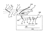
- FIG. 3 is a diagram showing a cross section of a vehicle equipped with the head-up display according to the first embodiment.
- FIG. 2 is a schematic diagram illustrating a configuration of a head-up display according to Embodiment 1.
- FIG. 3 is a schematic diagram for explaining a far vision distance and a near vision distance of the head-up display in the first embodiment 7 is a graph showing a change in viewing distance with respect to a relative position of the second lens with respect to the display device.
- FIG. 9 is a schematic diagram showing a configuration of an imaging position variable unit in the head-up display according to the third embodiment. Schematic diagram showing the configuration of a head-up display according to Embodiment 4.
- FIG. 30 shows a cross section A of the second lens in the tenth embodiment.
- FIG. 28 is a diagram showing a B cross section of the second lens in the tenth embodiment.
- 30 shows a C section of the first lens in Embodiment 10.
- FIG. 30 shows a D section of the first lens in Embodiment 10.
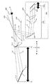
- FIG. 1 is a diagram showing a cross section of a vehicle 200 equipped with a head-up display 100 according to Embodiment 1 of the present disclosure.
- the head-up display 100 is disposed inside a dashboard 210 below a windshield 220 of a vehicle 200.
- the observer D recognizes the image projected from the head-up display 100 as a virtual image I.
- the position of the virtual image I is variable between a far focus position that is far from the observer D and a near focus position that is close to the observer D.
- the virtual image I may sink into the road surface R. Therefore, by inclining the virtual image I, it is possible to prevent the virtual image I from sinking into the road surface R, and to realize a natural AR (Augmented Reality) display without giving the observer D a sense of incongruity. It is possible to improve the cognitive ability of the observer D).
- FIG. 2 is a schematic diagram showing a configuration of the head-up display 100 according to the present embodiment.
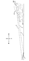
- FIG. 3 is a schematic diagram for describing the distance distance and the distance distance of the head-up display 100 according to the present embodiment.
- the head-up display 100 includes a display device 110 and an imaging position changing unit 150 including a projection optical system 140.
- the display device 110 is an optical member having a diffusion characteristic, and projects an image displayed on the display device 110 onto the windshield 220 via the projection optical system 140. The projected light is reflected by the windshield 220 and guided to the viewpoint area 300 of the observer D.
- the head-up display 100 myopia position to visually recognize the virtual image I 2 in the (near-focus position) the virtual image I 1 and hyperopia location in P1 (far-focus position) P2 to the observer D.
- the head-up display 100 has a variable focus function in which a virtual image position moves to a near vision position P1 and a far vision position P2.
- the viewpoint is a principal point when the eyes of the observer D are considered as a lens
- the viewpoint area 300 is a position of the observer D's viewpoint that can be visually recognized without missing the virtual images I 1 and I 2. Is the area to be used.
- the reference light beam Lc corresponds to an optical path from the center of the virtual images I 1 and I 2 to the viewpoint of the observer D.
- the reference light beam Lc visually recognized by the observer D actually reaches the observer D from the display device 110 via the optical system. Therefore, a light beam from the display device 110 to the observer D, which corresponds to the reference light beam Lc emitted from the center of the virtual images I 1 and I 2 , is also expressed as the reference light beam Lc.
- the optical paths corresponding to these light beams are similarly expressed as reference light beams Lc.
- the viewpoint of the observer D is at the center of the viewpoint area 300.
- the front refers to a direction where the windshield 220 of the vehicle 200 is located when viewed from the observer D.
- Backward is the opposite direction to forward.
- the term “downward” refers to the direction of the ground on which the vehicle 200 runs. Above is the opposite direction below.
- the display device 110 displays a display image based on control by a control unit such as a CPU (not shown).
- a control unit such as a CPU (not shown).
- a liquid crystal display device with a backlight Liquid Crystal Display
- an organic light emitting diode Organic Light-Emitting Diode
- a plasma display or the like
- an image may be generated using a screen that diffuses or reflects light, a projector, or a scanning laser.
- the display device 110 can display various information such as a road progress guidance display, a distance to a preceding vehicle, a remaining battery power of a vehicle, and a current vehicle speed.
- the display device 110 electronically distorts the image in advance according to the distortion generated in the projection optical system 140 and the windshield 220 and the position of the observer D obtained by a camera (not shown).
- the observer D can visually recognize the good virtual images I 1 and I 2 .
- the display device 110 shifts display pixels of a plurality of wavelengths for each display position in advance in accordance with the chromatic aberration generated by the projection optical system 140 to display good virtual images I 1 and I 2 to the observer D. It can be visually recognized.
- the projection optical system 140 includes a first lens 123, a second lens 124, and a first mirror 125 as optical elements.
- the first lens 123 and the second lens 124 are, for example, free-form surface lenses
- the first mirror 125 is, for example, a free-form surface mirror.
- the projection optical system 140 projects the image enlarged by the first lens 123 and the second lens 124 onto the windshield 220 by reflecting the image via the first mirror 125.
- the second lens 124 is movable in the direction of arrow A between a position approaching the first lens 123 as shown by a solid line in FIG. 2 and a position away from the first lens 123 as shown by a dotted line in FIG. It is configured. If the second lens 124 moves away to the first lens 123, the virtual image I 1 to myopia position P1 is formed, when the second lens 124 is in the position closer to the first lens 123, the virtual image I in hyperopic position P2 2 are formed. As described above, in the present embodiment, the imaging position can be changed by configuring the second lens 124 of the projection optical system 140 to be movable.
- the head-up display 100 projects the virtual images I 1 and I 2 on the windshield 220 and superimposes the virtual images I 1 and I 2 on the real image in front of the vehicle 200, so that the observer D, who is the driver, can move the path without greatly moving the line of sight and the focusing of the eyes. Guidance or warning can be confirmed, thereby improving safety during driving.
- the virtual image I 2 in the hyperopic position P2 it is possible to cause dent the road surface R, which may viewer D becomes unnatural expression experience discomfort. Therefore, in the present embodiment, the virtual images I 1 and I 2 are configured to be displayed obliquely with respect to the line of sight of the observer D. In order to display the virtual images I 1 and I 2 at an angle in this manner, the display device 110 is arranged at a predetermined angle counterclockwise with respect to the reference light beam Lc, as shown in FIG.
- the inter-vehicle distance is relatively long, so the observer D drives while looking far away. Therefore, in this case, by increasing the viewing distance to the virtual image, the viewing distance adjustment of the eyes can be reduced, and the visibility is improved.
- the vehicle is traveling at a low speed, the distance between the vehicle and the vehicle in front is short, and the observer D drives while watching the vehicle in front while watching the vehicle in front. Therefore, in this case, by reducing the viewing distance to the virtual image, the adjustment of the viewing distance of the eyes is reduced, and the visibility is improved. Further, by making the distance of the virtual image less distant from the distance of the vehicle ahead, the sense of discomfort can be reduced.
- the second lens 124 of the projection optical system 140 included in the imaging position varying unit 150 as described above and configured to be movable a short viewing distance is the imaging position of the virtual image I 1 myopic position P1
- the distance vision is the imaging position of the virtual image I 2 is on the long distance vision position P2, thereby enabling changing the imaging position of the virtual image.
- the projection optical system 140 included in the imaging position varying unit 150 sets the height of the viewpoint position of the observer D with respect to the road surface R to a predetermined height and sets the depression angle to a predetermined angle.
- the lower end I 2 _l of the virtual image I 2 at the far vision position P2 is set to be higher than the position of the road surface R as shown by a dotted circle C in FIG.
- the projection optical system 140 sets the height of the viewpoint position of the observer D with respect to the road surface R to a predetermined height and sets the depression angle to a predetermined angle
- the lower end I 2 _l of the virtual image I 2 does not necessarily need to be at a position higher than the position of the road surface R. If the lower end of the main part of the virtual image I 2 is at a position higher than the position of the road surface R, the virtual image I 2 2 of the lower I 2 _l is no problem even if slightly lower than the road surface R.
- the "major portion" of the virtual image I 2 it is assumed that refers to a moiety that can be confirmed direction, etc. of the arrow of turn-by-turn indicated by the virtual image I 2, the meaning and content of the label, such as indicated by the virtual image I 2.
- the viewpoint position of the observer D in the vehicle 200 varies depending on the type of the vehicle 200, the height of the observer D, and the like, in the present embodiment, for example, 1.2 m is set as the height of the driver's line of sight.
- the predetermined height of the viewpoint position is set. However, this is only an example, and another numerical value may be used as the predetermined height of the viewpoint position.
- the depression angle ⁇ which is the angle of the reference light beam Lc with respect to the horizontal direction H of the vehicle 200 from the viewpoint position of the observer D, also varies depending on the height of the observer D, but in the present embodiment, for example, 3 ° ⁇ 4 ° is a predetermined angle of depression ⁇ . However, this is an example, and another numerical value may be used as the predetermined angle of the depression angle ⁇ .
- the angle of view is set such that the angle from the reference light beam Lc to the upper light beam Lu and the lower light beam Ll is 1.5 °.
- this is an example, and another numerical value may be used as the angle of view.
- myopia distance from the observer D of the lower end I 1 _l of the virtual image I 1 in myopia position P1 is 5 m
- hyperopia distance from the bottom I 2 _l observers D virtual image I 2 in the hyperopia position P2 is 10 m
- the upper end I 2 _u observers D virtual image I 2 in the hyperopic position P2 hyperopia distance from tilts the virtual image I 2 such that 15 m.
- the projection optical system 14 was set so that 2_1 was the position of the intersection of the road surface R and the lower light beam Ll.
- the virtual image I 2 in the hyperopia position P2 is prevented from sinks to the road surface R, it can be prevented feeling uncomfortable to the viewer D.
- the upper end I 2 — u of the virtual image I 2 at the far vision position P2 is The projection optical system 14 was set so as to be located above the intersection of the road surface R and the upper ray Lu. As a result, it is possible to prevent the upper end I 2 _u of the virtual image I 2 is not lower than the lower end I 2 _l, feeling uncomfortable to the viewer D.
- the amount of movement of the second lens 124 can be reduced by setting the projection optical system 140 as described above.
- the relationship between the viewing distance and the amount of movement of the lens will be described.
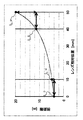
- FIG. 4 is a graph showing a change in viewing distance with respect to a relative position of the second lens 124 with respect to the display device 110.
- the viewing distance change amount per unit movement amount of the second lens 124 increases as the viewing distance increases. For example, when a virtual image perpendicular to the road surface R and at a viewing distance of 4 m from the observer D is considered as in the related art, if the second lens 124 is moved 10 mm from the position (0 mm) at that time to 10 mm. The visual distance to the virtual image changes from 4 m to 5 m, and the visual distance change amount is 1 m.
- the second lens 124 is moved 10 mm from the position at that time (40 mm) to 50 mm. Then, the viewing distance to the virtual image changes from about 12 m to 20 m, and the viewing distance change amount becomes 5 m.
- the relationship between the viewing distance and the movement amount of the lens as described above may be replaced with the relationship between the viewing distance and the movement amount of the display device 110. Can be.
- the projection optical system 140 of the head-up display 100 in the present embodiment sets the lower end I 2 _l of the virtual image I 2 or the lower end of the main part of the virtual image I 2 at the far vision position P2 higher than the position of the road surface R. since setting is made so that the position, the virtual image I 2 in the hyperopia position P2 is prevented from sinks to the road surface R, can be prevented feeling uncomfortable to the viewer D.
- the projection optical system 140 of the head-up display 100 when the height of the viewpoint position of the observer D with respect to the road surface R is a predetermined height and the depression angle is a predetermined angle, the virtual image at the far vision position P2 I2 the upper end I2_u of, than the height from the road surface R of the lower I 2 _l, because it is set to the projection optical system 14 to the height becomes higher position from the road surface R of the upper end I2_u, the virtual image I 2 upper I 2 _u of not lower than the lower end I2_l, it is possible to prevent the feeling uncomfortable to the viewer D.
- the projection optical system 140 of the head-up display 100 in the present embodiment reduces the amount of movement of the second lens 124 by inclining the virtual images I 1 and I 2 as described above, and The load can be reduced.
- Head-up display 100 as an example of the head-up display according to Embodiment 1 is a head-up display that allows observer D to visually recognize virtual images I 1 and I 2 .
- the virtual images I 1 and I 2 are inclined with respect to the line of sight of the observer D.
- the head-up display 100 includes a display device 110 as an example of a display device, and a projection optical system 140, and shifts the position of the virtual image to a far-sighted position P2 far from the observer D and a near-sighted position P1 near the observer D.
- An image forming position changing unit 150 for changing the image forming position is provided.
- Imaging position variable section 150 when the viewer height of the viewpoint position of D with respect to the road surface R is a running surface of the vehicle 200 as a moving body to a predetermined height, the main part of the virtual image I 2 in the hyperopic position P2 the lower end is set so as to position higher than the position of the road surface R, of the virtual image I 2 in the far vision position P2 the upper I 2 _u, than the height from the road surface R of the lower I 2 _l, the upper I 2 _u The position is set so that the height from the road surface R becomes higher.
- the projection optical system 140 includes a first lens 123 and a second lens 124 as a plurality of optical elements, and an image forming position changing unit.
- Reference numeral 150 denotes at least one of the first lens 123 and the second lens 124, for example, the second lens 124 when a light beam corresponding to the center of the virtual images I 1 and I 2 is used as the reference light beam Lc.
- the virtual image I 2 in the hyperopia position P2 is prevented from sinks to the road surface R, can be prevented feeling uncomfortable to the viewer D. Further, according to the head-up display 100 according to the first embodiment, it is possible to prevent the upper end I 2 _u of the virtual image I 2 is not lower than the lower end I 2 _l, feeling uncomfortable to the viewer D. Furthermore, according to head-up display 100 according to Embodiment 1, the amount of movement of second lens 124 can be reduced, and the load on the lens driving mechanism can be reduced.
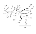
- FIG. 5 is a schematic diagram illustrating a configuration of a head-up display 100 according to Embodiment 2.
- the position where the display device 110 included in the imaging position variable unit 150 approaches the second lens 124 as shown by a dotted line in FIG.
- the solid line in FIG. 5 it is configured to be movable in the direction of arrow A to a position away from the second lens 124.
- the virtual image I 1 When in the position where the display device 110 closer to the second lens 124, the virtual image I 1 is formed in a myopic position P1, when in the position where the display device 110 moves away from the second lens 124, the virtual image far vision position P2 I 2 is formed.
- the image forming position can be changed by configuring the display device 110 to be movable.
- the virtual images I 1 and I 2 are configured to be displayed so as to be inclined with respect to the line of sight of the observer D.
- the display device 110 is arranged at a predetermined angle counterclockwise with respect to the reference light beam Lc, as shown in FIG.
- the projection optical system 140 included in the imaging position variable unit 150 is configured such that the height of the viewpoint position of the observer D with respect to the road surface R is a predetermined height, and the depression angle is a predetermined angle.
- the lower end of the main part of the virtual image I 2 in the hyperopia position P2 is set to the position higher than the position of the road surface R.
- the projection optical system 140 similarly sets the upper end I 2 — u of the virtual image I 2 at the far vision position P2. the, than the height from the road surface R of the lower I 2 _l, is configured to the height becomes higher position from the road surface R of the upper end I 2 _u.
- the virtual image I 2 in the hyperopia position P2 is prevented from sinks to the road surface R, it can be prevented feeling uncomfortable to the viewer D. Further, according to this embodiment, the upper end I 2 _u of the virtual image I2 is not lower than the lower end I 2 _l, it is possible to prevent the feeling uncomfortable to the viewer D.
- Head-up display 100 as an example of the head-up display according to Embodiment 2 is a head-up display that allows observer D to visually recognize virtual images I 1 and I 2 .
- the virtual images I 1 and I 2 are inclined with respect to the line of sight of the observer D.
- the head-up display 100 includes a display device 110 as an example of a display device, and a projection optical system 140, and shifts the position of the virtual image to a far-sighted position P2 far from the observer D and a near-sighted position P1 near the observer D.
- An image forming position changing unit 150 for changing the image forming position is provided.
- Imaging position variable section 150 when the viewer height of the viewpoint position of D with respect to the road surface R is a running surface of the vehicle 200 as a moving body to a predetermined height, the main part of the virtual image I 2 in the hyperopic position P2 the lower end is set so as to position higher than the position of the road surface R, of the virtual image I 2 in the far vision position P2 the upper I 2 _u, than the height from the road surface R of the lower I 2 _l, the upper I 2 _u The position is set to be higher than the height from the road surface R.
- the imaging position varying unit 150 performs display when the light beam corresponding to the center of the virtual images I 1 and I 2 is set as the reference light beam Lc.
- the distance between the device 110 and the projection optical system 140 in the direction of the reference light beam Lc the positions of the virtual images I 1 and I 2 are changed.
- the virtual image I 2 in the hyperopia position P2 is prevented from sinks to the road surface R, can be prevented feeling uncomfortable to the viewer D. Further, according to the head-up display 100 according to the second embodiment, it is possible to prevent the upper end I 2 _u of the virtual image I 2 is not lower than the lower end I 2 _l, feeling uncomfortable to the viewer D.
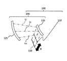
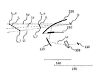
- FIG. 6 is a schematic diagram illustrating a configuration of an imaging position varying unit 150 in the head-up display 100 according to the third embodiment.
- the projection optical system 140 included in the imaging position varying unit 150 is an optical element of the second lens 124 described in the second embodiment.
- a second mirror 126 and a first mirror 125 are provided instead.
- the first mirror 125 and the second mirror 126 are, for example, free-form surface mirrors.
- the projection optical system 140 projects the image enlarged by the second mirror 126 onto the windshield 220 by reflecting the image through the first mirror 125.
- the display device 110 is located forward of the vehicle 200 with respect to the second mirror 126. Further, as in Embodiment 2, the display device 110 is set at a position approaching the second mirror 126 as shown by a dotted line in FIG. 6 and a position away from the second mirror 126 as shown by a solid line in FIG. It is configured to be movable in the direction of arrow B. When in the position where the display device 110 closer to the second mirror 126, the virtual image I 1 is formed in a myopic position P1, when in the position where the display device 110 moves away from the second mirror 126, the virtual image far vision position P2 I 2 is formed. As described above, in the present embodiment, the image forming position can be changed by configuring the display device 110 to be movable.
- the virtual images I 1 and I 2 are configured to be displayed so as to be inclined with respect to the line of sight of the observer D.
- the display device 110 is arranged at a predetermined angle clockwise with respect to the reference light beam Lc, as shown in FIG.
- the projection optical system 140 included in the imaging position variable unit 150 is configured such that the height of the viewpoint position of the observer D with respect to the road surface R is a predetermined height, and the depression angle is a predetermined angle.
- the lower end of the main part of the virtual image I 2 in the hyperopia position P2 is set to the position higher than the position of the road surface R.
- the projection optical system 140 similarly sets the upper end I 2 — u of the virtual image I 2 at the far vision position P2. Is set to a position where the height from the road surface R at the upper end I 2 _u is higher than the height from the road surface R at the lower end I 2 _l.
- the virtual image I 2 in the hyperopia position P2 is prevented from sinks to the road surface R, it can be prevented feeling uncomfortable to the viewer D. Further, according to this embodiment, it is possible to prevent the upper end I 2 _u of the virtual image I 2 is not lower than the lower end I 2 _l, feeling uncomfortable to the viewer D.
- Head-up display 100 as an example of the head-up display according to Embodiment 3 is a head-up display that allows observer D to visually recognize virtual images I 1 and I 2 .
- the virtual images I 1 and I 2 are inclined with respect to the line of sight of the observer D.
- the head-up display 100 includes a display device 110 as an example of a display device, and a projection optical system 140, and shifts the position of the virtual image to a far-sighted position P2 far from the observer D and a near-sighted position P1 near the observer D.
- An image forming position changing unit 150 for changing the image forming position is provided.
- Imaging position variable section 150 when the viewer height of the viewpoint position of D with respect to the road surface R is a running surface of the vehicle 200 as a moving body to a predetermined height, the main part of the virtual image I 2 in the hyperopic position P2 the lower end is set so as to position higher than the position of the road surface R, of the virtual image I 2 in the far vision position P2 the upper I 2 _u, than the height from the road surface R of the lower I 2 _l, the upper I 2 _u The position is set so that the height from the road surface R becomes higher.
- the imaging position varying unit 150 performs display when the light beam corresponding to the center of the virtual images I 1 and I 2 is set as the reference light beam Lc.
- the distance between the device 110 and the projection optical system 140 in the direction of the reference light beam Lc the positions of the virtual images I 1 and I 2 are changed.
- the virtual image I 2 in the hyperopia position P2 is prevented from sinks to the road surface R, can be prevented feeling uncomfortable to the viewer D. Further, according to this embodiment, it is possible to prevent the upper end I 2 _u of the virtual image I 2 is not lower than the lower end I 2 _l, feeling uncomfortable to the viewer D.
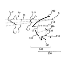
- FIG. 7 is a schematic diagram showing a configuration of a head-up display 100 according to Embodiment 4.
- the projection optical system 140 included in the imaging position varying unit 150 serves as an optical element of the first mirror 125 described in the third embodiment.
- a third mirror 127 and a first mirror 125 are provided instead.
- the second mirror 126 is, for example, a free-form surface mirror.
- the third mirror 127 is a variable power optical element capable of changing power.
- the third mirror 127 is, for example, a variable curvature mirror in which a mirror surface is formed by an electrostrictive element and the curvature of the curved surface is changed by applying a voltage.
- a mirror whose curvature of the curved surface is made variable by another method may be used.
- the imaging position changing unit 150 changes the positions of the virtual images I 1 and I 2 by changing the power of the third mirror 127 as a power variable optical element.
- the third mirror 127 is configured to be deformable into a shape having a large curvature as shown by a dotted line in FIG. 7 and a shape having a small curvature as shown by a solid line in FIG. I have. If the third mirror 127 is a small form of curvature, the virtual image I 1 to myopia position P1 is formed, when the third mirror 127 is larger shape of curvature, the virtual image I 2 in hyperopic position P2 Is formed. As described above, in the present embodiment, the imaging position can be changed by changing the power of the third mirror 127.
- the virtual images I 1 and I 2 are configured to be displayed so as to be inclined with respect to the line of sight of the observer D.
- the display device 110 is arranged at a predetermined angle clockwise with respect to the reference light beam Lc as shown in FIG.
- the projection optical system 140 included in the imaging position variable unit 150 is configured such that the height of the viewpoint position of the observer D with respect to the road surface R is a predetermined height, and the depression angle is a predetermined angle.
- the lower end of the main part of the virtual image I 2 in the hyperopia position P2 is set to the position higher than the position of the road surface R.
- the projection optical system 140 similarly sets the upper end I 2 — u of the virtual image I 2 at the far vision position P2. the, than the height from the road surface R of the lower I 2 _l, is configured to the height becomes higher position from the road surface R of the upper end I 2 _u.
- the virtual image I 2 in the hyperopia position P2 is prevented from sinks to the road surface R, it can be prevented feeling uncomfortable to the viewer D. Further, according to this embodiment, it is possible to prevent the upper end I 2 _u of the virtual image I 2 is not lower than the lower end I 2 _l, feeling uncomfortable to the viewer D.
- Head-up display 100 as an example of the head-up display according to Embodiment 4 is a head-up display that allows observer D to visually recognize virtual images I 1 and I 2 .
- the virtual images I 1 and I 2 are inclined with respect to the line of sight of the observer D.
- the head-up display 100 includes a display device 110 as an example of a display device, and a projection optical system 140, and shifts the position of the virtual image to a far-sighted position P2 far from the observer D and a near-sighted position P1 near the observer D.
- An image forming position changing unit 150 for changing the image forming position is provided.
- Imaging position variable section 150 when the viewer height of the viewpoint position of D with respect to the road surface R is a running surface of the vehicle 200 as a moving body to a predetermined height, the main part of the virtual image I 2 in the hyperopic position P2 the lower end is set so as to position higher than the position of the road surface R, of the virtual image I 2 in the far vision position P2 the upper I 2 _u, than the height from the road surface R of the lower I 2 _l, the upper I 2 _u The position is set so that the height from the road surface R becomes higher.
- the projection optical system 140 includes a third mirror 127 as a variable power optical element capable of changing power, and forms an image.
- the position changing unit 150 changes the positions of the virtual images I 1 and I 2 by changing the power of the third mirror 127 as a power variable optical element.
- the virtual image I 2 in the hyperopia position P2 is prevented from sinks to the road surface R, can be prevented feeling uncomfortable to the viewer D. Further, according to this embodiment, it is possible to prevent the upper end I 2 _u of the virtual image I 2 is not lower than the lower end I 2 _l, feeling uncomfortable to the viewer D.
- FIG. 8 is a schematic diagram showing a configuration of a head-up display 100 according to Embodiment 5.
- the projection optical system 140 included in the imaging position varying unit 150 includes a third lens 128 and a first mirror 125 as optical elements. Prepare.
- the third lens 128 is a power variable optical element capable of changing power.
- the third lens 128 is, for example, a varifocal lens whose lens shape can be changed by applying pressure with an electromagnetic actuator.
- the imaging position varying unit 150 changes the positions of the virtual images I 1 and I 2 by changing the power of the third lens 128 as a power variable optical element.
- the third lens 128 is a negative lens, and has a shape in which the lens thickness is increased as indicated by a dotted line in FIG. 8 and a shape in which the lens thickness is decreased as indicated by a solid line in FIG. , Is configured to be deformable.
- the lens thickness of the third lens 128 increases, it indicates a state in which the power of the negative lens increases, and when the lens thickness of the third lens 128 decreases, it indicates a state in which the power of the negative lens decreases. I have.
- the imaging position can be changed by changing the power of the third lens 128.
- the power of the third lens 128 is a positive power
- lens thickness becomes thicker
- the positive power becomes stronger
- far focus the virtual image I 2 is formed at a position P2
- the lens is thin becomes star power becomes weak
- the virtual image I 1 is formed near focus position P1.
- the virtual images I 1 and I 2 are configured to be displayed so as to be inclined with respect to the line of sight of the observer D.
- the display device 110 is arranged at a predetermined angle clockwise with respect to the reference light beam Lc, as shown in FIG.
- the projection optical system 140 included in the imaging position variable unit 150 is configured such that the height of the viewpoint position of the observer D with respect to the road surface R is a predetermined height, and the depression angle is a predetermined angle.
- the lower end of the main part of the virtual image I 2 in the hyperopia position P2 is set to the position higher than the position of the road surface R.
- the projection optical system 140 similarly sets the upper end I 2 — u of the virtual image I 2 at the far vision position P2. the, than the height from the road surface R of the lower I 2 _l, is configured to the height becomes higher position from the road surface R of the upper end I 2 _u.
- the virtual image I 2 in the hyperopia position P2 is prevented from sinks to the road surface R, it can be prevented feeling uncomfortable to the viewer D. Further, according to this embodiment, it is possible to prevent the upper end I 2 _u of the virtual image I 2 is not lower than the lower end I 2 _l, feeling uncomfortable to the viewer D.
- Head-up display 100 as an example of the head-up display according to Embodiment 5 is a head-up display that allows observer D to visually recognize virtual images I 1 and I 2 .
- the virtual images I 1 and I 2 are inclined with respect to the line of sight of the observer D.
- the head-up display 100 includes a display device 110 as an example of a display device, and a projection optical system 140, and shifts the position of the virtual image to a far-sighted position P2 far from the observer D and a near-sighted position P1 near the observer D.
- An image forming position changing unit 150 for changing the image forming position is provided.
- Imaging position variable section 150 when the viewer height of the viewpoint position of D with respect to the road surface R is a running surface of the vehicle 200 as a moving body to a predetermined height, the main part of the virtual image I 2 in the hyperopic position P2 the lower end is set so as to position higher than the position of the road surface R, of the virtual image I 2 in the far vision position P2 the upper I 2 _u, than the height from the road surface R of the lower I 2 _l, the upper I 2 _u It is set to be a position where the height from is higher.
- the projection optical system 140 includes a third lens 128 as a power variable optical element capable of changing power, and forms an image.
- the position changing unit 150 changes the positions of the virtual images I 1 and I 2 by changing the power of the third lens 128 as a power variable optical element.
- the virtual image I 2 in the hyperopia position P2 is prevented from sinks to the road surface R, can be prevented feeling uncomfortable to the viewer D. Further, according to this embodiment, it is possible to prevent the upper end I 2 _u of the virtual image I 2 is not lower than the lower end I 2 _l, feeling uncomfortable to the viewer D.
- FIG. 9 is a schematic diagram showing a configuration of a head-up display 100 according to Embodiment 6.
- projection optical system 140 included in variable imaging position section 150 has first mirror 125, second mirror 126, and optical elements as optical elements.
- the fourth lens 129 is, for example, a free-form surface lens.
- the imaging position varying unit 150 changes the positions of the virtual images I 1 and I 2 by inserting and removing the fourth lens 129 in the direction of arrow C.
- the fourth lens 129 is located at a position off the optical path from the display device 110 to the second lens 126 as shown by a solid line in FIG. 9 and a display device as shown by a dotted line in FIG. It is configured to be movable to a position arranged on the optical path from 110 to the second lens 126.
- the fourth lens 129 When the fourth lens 129 is in a position out of the optical path from the display device 110 to the second lens 126, the virtual image I 1 is formed in a myopic position P1, the fourth lens 129 is a second lens from the display device 110 126 when a position on an optical route to the virtual image I 2 is formed hyperopia position P2.
- the image forming position can be changed by inserting and removing the fourth lens 129.
- the power of the fourth lens 129 is opposite, the perspective relationship of the position of the virtual image is also inverted.
- the virtual images I 1 and I 2 are configured to be displayed so as to be inclined with respect to the line of sight of the observer D.
- the display device 110 is arranged at a predetermined angle clockwise with respect to the reference light beam Lc, as shown in FIG.
- the projection optical system 140 included in the imaging position variable unit 150 is configured such that the height of the viewpoint position of the observer D with respect to the road surface R is a predetermined height, and the depression angle is a predetermined angle.
- the lower end of the main part of the virtual image I 2 in the hyperopia position P2 is set to the position higher than the position of the road surface R.
- the projection optical system 140 similarly sets the upper end I 2 — u of the virtual image I 2 at the far vision position P2. the, than the height from the road surface R of the lower I 2 _l, is configured to the height becomes higher position from the road surface R of the upper end I 2 _u.
- the virtual image I 2 in the hyperopia position P2 is prevented from sinks to the road surface R, it can be prevented feeling uncomfortable to the viewer D. Further, according to this embodiment, it is possible to prevent the upper end I 2 _u of the virtual image I 2 is not lower than the lower end I 2 _l, feeling uncomfortable to the viewer D.
- Head-up display 100 as an example of the head-up display according to Embodiment 6 is a head-up display that allows observer D to visually recognize virtual images I 1 and I 2 .
- the virtual images I 1 and I 2 are inclined with respect to the line of sight of the observer D.
- the head-up display 100 includes a display device 110 as an example of a display device, and a projection optical system 140, and shifts the position of the virtual image to a far-sighted position P2 far from the observer D and a near-sighted position P1 near the observer D.
- An image forming position changing unit 150 for changing the image forming position is provided.
- Imaging position variable section 150 when the viewer height of the viewpoint position of D with respect to the road surface R is a running surface of the vehicle 200 as a moving body to a predetermined height, the main part of the virtual image I 2 in the hyperopic position P2 the lower end is set so as to position higher than the position of the road surface R, of the virtual image I 2 in the far vision position P2 the upper I 2 _u, than the height from the road surface R of the lower I 2 _l, the upper I 2 _u The position is set so that the height from the road surface R becomes higher.
- projection optical system 140 includes first mirror 125, second mirror 126, and fourth lens 129 as a plurality of optical elements.
- the imaging position varying unit 150 moves the fourth lens 129, which is at least one of the plurality of optical elements, to a position intersecting the upper ray and the lower ray, and a position not intersecting. By doing so, the positions of the virtual images I 1 and I 2 are changed.
- the virtual image I 2 in the hyperopia position P2 is prevented from sinks to the road surface R, can be prevented feeling uncomfortable to the viewer D. Further, according to this embodiment, it is possible to prevent the upper end I 2 _u of the virtual image I 2 is not lower than the lower end I 2 _l, feeling uncomfortable to the viewer D.
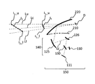
- FIG. 10 is a schematic diagram showing a configuration of a head-up display 100 according to Embodiment 7.
- the projection optical system 140 included in the imaging position varying unit 150 has a first mirror 125, a second mirror 126, and a semi-transmissive as optical elements. It includes a reflecting mirror 130 and a fourth mirror 131 configured to be movable in the direction of arrow E shown in FIG. 10 along the reference light beam Lc.
- the imaging position varying unit 150 changes the positions of the virtual images I 1 and I 2 by moving the fourth mirror 131 in the direction of arrow E.
- the fourth mirror 131 is configured to be movable between a position near the transflective mirror 130 and a position away from the transflective mirror 130.
- the virtual image I 1 is formed in a myopic position P1
- hyperopia virtual image I 2 is formed at a position P2.
- the imaging position can be changed by moving the fourth mirror 131.
- the fourth mirror 131 is an optical element that changes the optical path length from the incident surface to the emission surface of the projection optical system 140, and the imaging position variable unit 150 changes the optical path length of the projection optical system 140 By changing the position of the mirror 131, the positions of the virtual images I 1 and I 2 are changed.
- the virtual images I 1 and I 2 are configured to be displayed so as to be inclined with respect to the line of sight of the observer D.
- the display device 110 is arranged at a predetermined angle clockwise with respect to the reference light beam Lc, as shown in FIG.
- the projection optical system 140 included in the imaging position variable unit 150 is configured such that the height of the viewpoint position of the observer D with respect to the road surface R is a predetermined height, and the depression angle is a predetermined angle.
- the lower end of the main part of the virtual image I 2 in the hyperopia position P2 is set to the position higher than the position of the road surface R.
- the projection optical system 140 similarly sets the upper end I 2 — u of the virtual image I 2 at the far vision position P2. the, than the height from the road surface R of the lower I 2 _l, is configured to the height becomes higher position from the road surface R of the upper end I 2 _u.
- the virtual image I 2 in the hyperopia position P2 is prevented from sinks to the road surface R, it can be prevented feeling uncomfortable to the viewer D. Further, according to this embodiment, it is possible to prevent the upper end I 2 _u of the virtual image I 2 is not lower than the lower end I 2 _l, feeling uncomfortable to the viewer D. Furthermore, the projection optical system 140 of the head-up display 100 in the present embodiment reduces the amount of movement of the fourth mirror 131 by inclining the virtual images I 1 and I 2 as described above, The load on the drive mechanism can be reduced.
- Head-up display 100 as an example of the head-up display according to Embodiment 7 is a head-up display that allows observer D to visually recognize virtual images I 1 and I 2 .
- the virtual images I 1 and I 2 are inclined with respect to the line of sight of the observer D.
- the head-up display 100 includes a display device 110 as an example of a display device, and a projection optical system 140, and shifts the position of the virtual image to a far-sighted position P2 far from the observer D and a near-sighted position P1 near the observer D.
- An image forming position changing unit 150 for changing the image forming position is provided.
- Imaging position variable section 150 when the viewer height of the viewpoint position of D with respect to the road surface R is a running surface of the vehicle 200 as a moving body to a predetermined height, the main part of the virtual image I 2 in the hyperopic position P2 the lower end is set so as to position higher than the position of the road surface R, of the virtual image I 2 in the far vision position P2 the upper I 2 _u, than the height from the road surface R of the lower I 2 _l, the upper I 2 _u The position is set so that the height from the road surface R becomes higher.
- projection optical system 140 includes first mirror 125, second mirror 126, transflective mirror 130 as a plurality of optical elements, and , A fourth mirror 131, which is at least one of the plurality of optical elements, changes the optical path length from the display device 110 to the positions of the virtual images I 1 and I 2.
- the imaging position varying unit 150 changes the position of the fourth mirror 131 which is an optical element that changes the optical path length, thereby changing the positions of the virtual images I 1 and I 2 .
- the virtual image I 2 in the hyperopia position P2 is prevented from sinks to the road surface R, can be prevented feeling uncomfortable to the viewer D. Further, according to this embodiment, it is possible to prevent the upper end I 2 _u of the virtual image I 2 is not lower than the lower end I 2 _l, feeling uncomfortable to the viewer D.
- FIG. 11 is a schematic diagram showing a configuration of a head-up display 100 according to Embodiment 8.
- the projection optical system 140 included in the imaging position varying unit 150 includes, as optical elements, a first mirror 125, a second mirror 126, and a half mirror.
- the transmission / reflection mirror 130 is provided.
- the image forming position changing unit 150 includes two display devices, a display device 110 and a display device 111.
- the display device 110 is arranged at a position closer to the transflective mirror 130 than the display device 111, and the display device 111 is arranged at a position farther from the transflective mirror 130 than the display device 110. That is, the display devices 110 and 111 are arranged at positions where the optical path length from the display device to the projection optical system 140 is different from each other.
- the imaging position changing unit 150 changes the position of the virtual images I 1 and I 2 by switching the display device that displays an image to either the display device 110 or the display device 111. Let it.
- the virtual image I 1 is formed in a myopic position P1
- the virtual image I 2 in hyperopic position P2 It is formed.
- the image forming position can be changed by switching the display device that displays an image to either the display device 110 or the display device 111.
- the second mirror 126 is used in the present embodiment, a lens such as the second lens 124 is used instead of the second mirror 126 as in the second embodiment shown in FIG. Can obtain the same effect.
- the virtual images I 1 and I 2 are configured to be displayed so as to be inclined with respect to the line of sight of the observer D.
- the display device 110 is arranged at a predetermined angle clockwise with respect to the reference light beam Lc, as shown in FIG.
- the projection optical system 140 included in the imaging position variable unit 150 is configured such that the height of the viewpoint position of the observer D with respect to the road surface R is a predetermined height, and the depression angle is a predetermined angle.
- the lower end of the main part of the virtual image I 2 in the hyperopia position P2 is set to the position higher than the position of the road surface R.
- the projection optical system 140 similarly sets the upper end I 2 — u of the virtual image I 2 at the far vision position P2. the, than the height from the road surface R of the lower I 2 _l, is configured to the height becomes higher position from the road surface R of the upper end I 2 _u.
- the virtual image I 2 in the hyperopia position P2 is prevented from sinks to the road surface R, it can be prevented feeling uncomfortable to the viewer D. Further, according to this embodiment, it is possible to prevent the upper end I 2 _u of the virtual image I 2 is not lower than the lower end I 2 _l, feeling uncomfortable to the viewer D.
- Head-up display 100 as an example of the head-up display according to Embodiment 8 is a head-up display that allows observer D to visually recognize virtual images I 1 and I 2 .
- the virtual images I 1 and I 2 are inclined with respect to the line of sight of the observer D.
- the head-up display 100 includes a display device 110 as an example of a display device, and a projection optical system 140, and shifts the position of the virtual image to a far-sighted position P2 far from the observer D and a near-sighted position P1 near the observer D.
- An image forming position changing unit 150 for changing the image forming position is provided.
- Imaging position variable section 150 when the viewer height of the viewpoint position of D with respect to the road surface R is a running surface of the vehicle 200 as a moving body to a predetermined height, the main part of the virtual image I 2 in the hyperopic position P2 the lower end is set so as to position higher than the position of the road surface R, of the virtual image I 2 in the far vision position P2 the upper I 2 _u, than the height from the road surface R of the lower I 2 _l, the upper I 2 _u It is set to be a position where the height from the road surface R becomes higher.
- head-up display 100 as an example of the head-up display according to Embodiment 8 includes two display devices, display device 110 and display device 11, as display devices.
- the optical path lengths from the respective display devices 110 and 111 to the positions of the virtual images I 1 and I 2 are arranged at different positions.
- the imaging position changing unit 150 changes the positions of the virtual images I 1 and I 2 by switching the respective display devices 110 and 111 to display images.
- the virtual image I 2 in the hyperopia position P2 is prevented from sinks to the road surface R, can be prevented feeling uncomfortable to the viewer D. Further, according to this embodiment, it is possible to prevent the upper end I 2 _u of the virtual image I 2 is not lower than the lower end I 2 _l, feeling uncomfortable to the viewer D.
- Embodiments 1 to 8 have been described as examples of the technology disclosed in the present application. However, the technology in the present disclosure is not limited to this, and can be applied to embodiments in which changes, replacements, additions, omissions, and the like are made. Further, it is also possible to form a new embodiment by combining the components described in the first to eighth embodiments.
- FIG. 12 is a schematic diagram showing a configuration of a head-up display 100 according to Embodiment 9.
- the modes in which the display devices 110 and 111 are tilted with respect to the reference light beam Lc in order to tilt the virtual images I 1 and I 2 have been described.
- the head-up display 100 of the present disclosure is not limited to such an aspect.
- the display surface of the display device 110 is arranged perpendicularly to the reference light beam Lc, and the power of the lens 132 is given strength in the vertical direction.
- the focal plane F is inclined by continuously changing the power of the lens 132 in the vertical direction. Even in this manner, the virtual images I 1 and I 2 can be inclined.
- the focal plane F is a composite focal plane of the windshield 220 and the virtual image system.
- the power can be continuously changed in the vertical direction of the mirror to tilt the focal plane F and tilt the virtual images I 1 and I 2 .
- the projection optical system 140 includes a lens or a mirror as a plurality of optical elements, and at least one optical element of the plurality of optical elements.
- a light beam corresponding to the center of the virtual images I 1 and I 2 is set as the reference light beam Lc, at least one of the incident surface and the output surface is inclined with respect to the reference light beam Lc. .
- the projection optical system 140 included in the imaging position varying unit 150 sets the height of the viewpoint position of the observer D with respect to the road surface R to a predetermined height, and sets the depression angle to a predetermined angle.
- the projection optical system 140 similarly sets the upper end I 2 — u of the virtual image I 2 at the far vision position P2. the, than the height from the road surface R of the lower I 2 _l, is configured to the height becomes higher position from the road surface R of the upper end I 2 _u.
- the virtual image I 2 in the hyperopia position P2 is prevented from sinks to the road surface R, it can be prevented feeling uncomfortable to the viewer D. Further, according to this embodiment, it is possible to prevent the upper end I 2 _u of the virtual image I 2 is not lower than the lower end I 2 _l, feeling uncomfortable to the viewer D.
- FIG. 13 is a schematic diagram showing a configuration of a head-up display 100 according to Embodiment 10.
- the projection optical system 140 included in the imaging position varying unit 150 includes, as optical elements, a first mirror 125, a first lens 133, and a It has two lenses 134.
- the image forming position changing unit 150 includes the display device 110.
- the first lens 133 is a free-form surface lens as an example, and has a positive power.
- the first lens 133 weaken the positive power on the side of the lower beam Ll passes to reach the lower side of the virtual image I 1, I 2, light rays Lu on reaching the upper side of the virtual image I 1, I 2 passes The positive power on the side was increased.
- the second lens 134 is a free-form surface lens as an example, and has a negative power.
- the second lens 134 is strongly negative power side of the lower beam Ll passes to reach the lower side of the virtual image I 1, I 2, light rays Lu on reaching the upper side of the virtual image I 1, I 2 passes Weakened the negative power on the side.
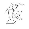
- FIG. 14 is a perspective view of the second lens 134.
- a cross section of the second lens 134 when the plane through which the lower ray Ll that reaches the lower side of the virtual images I 1 and I 2 passes and the plane S1 intersects is referred to as an A cross section.
- the planes S1 and S2 are planes parallel to each other and parallel to the reference light beam Lc.
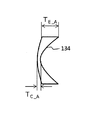
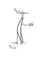
- FIG. 15A is a diagram illustrating a cross section A of the above-described second lens 134
- FIG. 15B is a diagram illustrating a cross section B of the above-described second lens 134.
- the thickness deviation ratio of the second lens 134 in the A section is relatively larger than that in the B section.
- the uneven thickness ratio is a ratio of the thickness of the peripheral portion of the lens to the thickness near the central portion of the lens, and has a value greater than 1.
- Figure 15A, in 15B represents the thickness in the vicinity of the lens center by "T C_A” or “T C_B” represents the thickness of the lens periphery "T E_A” or “T E_B".
- the thickness of the peripheral portion of the lens is defined by the thicker one of the edge portions on both sides of the lens, and the thickness near the center of the lens is defined by the thickness of the thinnest portion of the lens.
- the edge portion is defined by a region through which light rays pass (except for a clear holding allowance).
- the thickness deviation ratio R ut_A of the A section shown in FIG. 15A is expressed by the following equation.
- the fact that the thickness deviation ratio R ut_A on the A section side of the second lens 134 having negative power is greater than the thickness deviation ratio R ut_B on the B section side means that the A section side is more negative than the B section side. It means that the power is strong.
- the negative power on the section B side through which the upper ray Lu reaching the upper side of the virtual images I 1 and I 2 passes is weak, the focal length becomes longer, and the focal plane F shown in FIG. 13 is closer to the section B side. Located on the side.
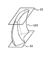
- FIG. 16 is a perspective view of the first lens 133.
- the planes S3 and S4 are planes parallel to each other and are planes parallel to the reference light beam Lc.
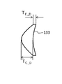
- FIG. 17A is a diagram illustrating a cross section C of the first lens 133 described above
- FIG. 17B is a diagram illustrating a D cross section of the first lens 133 described above.
- the thickness deviation ratio in the D section is relatively larger than that in the C section.
- the uneven thickness ratio is a ratio of the thickness of the peripheral portion of the lens to the thickness near the central portion of the lens, and takes a value smaller than 1.
- FIG. 17A in 17B, represents the thickness in the vicinity of the lens center by "T C_C” or “T C_D” represents the thickness of the lens periphery "T E_C” or “T E_D”.
- the thickness of the peripheral portion of the lens is defined by the thinner of the edge portions on both sides of the lens, and the thickness near the center of the lens is defined by the thickness of the thickest portion of the lens.
- the edge portion is defined by a region through which light rays pass (except for a clear holding allowance).
- the thickness deviation ratio R ut_C of the C section shown in FIG. 17A is expressed by the following equation.
- the fact that the thickness deviation ratio R ut_C on the C section side of the first lens 133 having positive power is larger than the thickness deviation ratio R ut_D on the D section side means that the C section side is more positive than the D section side. It means that the power is weak. That is, since the positive power on the C section side through which the lower light ray Ll reaching the lower side of the virtual images I 1 and I 2 passes is weak, the focal length becomes longer, and the focal plane F shown in FIG. Located on the far side. Further, since the positive power on the D-section side through which the upper ray Lu reaching the upper side of the virtual images I 1 and I 2 passes is strong, the focal length is shortened, and the focal plane F is located closer to the D-section side. .
- the focal plane F is changed by giving the vertical power to the negative power of the second lens 134 and by adding the vertical power to the positive power of the first lens 133.
- the virtual images I 1 and I 2 can be tilted.
- the virtual image I 1 of the image forming position at which viewing distance is short myopia position P1 in the virtual image I 2 of the imaging position at a viewing distance is long hyperopia position P2, the imaging position of the virtual image
- the imaging position of the virtual image In order to allow the second lens 134 of the projection optical system 140 included in the imaging position varying unit 150 to be movable, as in the first embodiment.
- the intensity of the negative power of the second lens 134 is given in the vertical direction, and the intensity of the positive power of the first lens 133 is given in the vertical direction.
- the focal plane F is inclined, and the virtual images I 1 and I 2 are inclined.
- the projection optical system 140 included in the imaging position varying unit 150 sets the height of the viewpoint position of the observer D with respect to the road surface R to a predetermined height and sets the depression angle to a predetermined angle.
- the lower end of the main part of the virtual image I 2 in the hyperopia position P2 is set to the position higher than the position of the road surface R.
- the projection optical system 140 similarly sets the upper end I 2 — u of the virtual image I 2 at the far vision position P2.
- Embodiments 1 to 10 even if the center of gravity moves forward of vehicle 200 and the posture of vehicle 200 turns forward, the upper end I 2 of virtual image I 2 at hyperopia position P2 is obtained.
- _U is set to a position where the height of the upper end I 2 _u from the road surface R is higher than the height of the lower end I 2 _l from the road surface R.
- the head-up display 100 is disposed below the dashboard 210, but may be disposed above the dashboard 210. Further, since the above-described embodiments are for exemplifying the technology according to the present disclosure, various changes, replacements, additions, omissions, and the like can be made within the scope of the claims or the equivalents thereof.
- a head-up display is a head-up display that is installed on a moving body such as a vehicle and displays an image as a virtual image to an observer.
- the display device displays an image, and the image is enlarged and projected.
- Projection optical system including, the position of the virtual image, far vision position far from the observer, comprising an imaging position variable unit to change the near vision position close to the observer, the imaging position variable unit in the far vision position
- the upper end of the virtual image is inclined at a second inclination angle in front of the moving object with respect to the vertical plane of the reference ray reaching the center of the viewpoint area where the observer's viewpoint is located, and the vertical direction of the reference With respect to the surface, the upper end of the virtual image is inclined forward of the moving object at a first inclination angle smaller than the second inclination angle.
- the head-up display of the present disclosure it is possible to prevent a virtual image at a far-sighted position from being immersed in the running surface, and to prevent an observer from feeling uncomfortable. Further, according to the head-up display of the present disclosure, the upper end of the virtual image does not become lower than the lower end, and it is possible to prevent the observer from feeling uncomfortable.
- the projection optical system includes at least one optical element, and the optical element includes a light ray reaching the upper side of the virtual image from a light ray reaching the lower side of the virtual image.
- the lower end of the virtual image at the far vision position is set to a second inclination angle that is higher than the position of the road surface in front of the moving object by a change in power up to the side where the vehicle passes. Therefore, it is possible to prevent the virtual image at the hyperopic position from being immersed in the running surface, and to prevent the observer from feeling uncomfortable. Further, according to the head-up display of the present disclosure, the upper end of the virtual image does not become lower than the lower end, and it is possible to prevent the observer from feeling uncomfortable.
- the projection optical system includes at least one optical element, and the optical element includes a light ray that reaches the upper side of the virtual image from a light ray that reaches the lower side of the virtual image. Due to the change in power up to the side where the vehicle passes, the lower end of the virtual image at the hyperopic position is located at a higher position than the road surface position in front of the mobile, even when the posture of the mobile is tilted. To a first inclination angle. Therefore, it is possible to prevent the virtual image at the hyperopic position from being immersed in the running surface, and to prevent the observer from feeling uncomfortable. Further, according to the head-up display of the present disclosure, the upper end of the virtual image is not lower than the lower end, and it is possible to prevent the observer from feeling uncomfortable.
- the projection optical system includes a plurality of optical elements
- the imaging position variable unit includes at least one of the plurality of optical elements and another optical element.
- the position of the virtual image is changed by changing the distance between the element and the reference light beam direction. Therefore, it is possible to prevent the virtual image at the hyperopic position from being immersed in the running surface, and to prevent the observer from feeling uncomfortable. Further, according to the head-up display of the present disclosure, the upper end of the virtual image does not become lower than the lower end, and it is possible to prevent the observer from feeling uncomfortable.
- the image-forming position changing unit changes the position of the virtual image by changing the distance between the display device and the projection optical system in the direction of the reference light beam. Therefore, it is possible to prevent the virtual image at the hyperopic position from being immersed in the running surface, and to prevent the observer from feeling uncomfortable. Further, according to the head-up display of the present disclosure, the upper end of the virtual image does not become lower than the lower end, and it is possible to prevent the observer from feeling uncomfortable.
- the projection optical system includes at least one optical element
- the imaging position variable unit sets the optical element such that the optical element intersects a position intersecting with an optical path from the display device and a position that does not intersect. Then, the position of the virtual image is changed. Therefore, it is possible to prevent the virtual image at the hyperopic position from being immersed in the running surface, and to prevent the observer from feeling uncomfortable. Further, according to the head-up display of the present disclosure, the upper end of the virtual image does not become lower than the lower end, and it is possible to prevent the observer from feeling uncomfortable.
- the projection optical system includes a plurality of optical elements, and at least one of the plurality of optical elements is an optical element that changes an optical path length of the projection optical system.
- the imaging position changing unit changes the position of the virtual image by changing the position of the optical element that changes the optical path length. Therefore, it is possible to prevent the virtual image at the far-sighted position from sinking into the running surface and prevent the observer from feeling uncomfortable. Further, according to the head-up display of the present disclosure, the upper end of the virtual image does not become lower than the lower end, and it is possible to prevent the observer from feeling uncomfortable.
- the head-up display of (1) two display devices are provided as display devices, and the two display devices are arranged at positions where the optical path lengths from the respective display devices to the projection optical system are different from each other.
- the image forming position changing unit changes the position of the virtual image by switching the respective display devices to display an image. Therefore, it is possible to prevent the virtual image at the hyperopic position from being immersed in the running surface, and to prevent the observer from feeling uncomfortable. Further, according to the head-up display of the present disclosure, the upper end of the virtual image does not become lower than the lower end, and it is possible to prevent the observer from feeling uncomfortable.
- the projection optical system includes a variable power optical element capable of changing power, and the imaging position variable unit changes the power of the variable power optical element. , Changing the position of the virtual image. Therefore, it is possible to prevent the virtual image at the hyperopic position from being immersed in the running surface, and to prevent the observer from feeling uncomfortable. Further, according to the head-up display of the present disclosure, the upper end of the virtual image does not become lower than the lower end, and it is possible to prevent the observer from feeling uncomfortable.
- the display device when the light beam corresponding to the center of the virtual image is used as the reference light beam, the display device has an image display inclined with respect to the reference light beam. . Therefore, it is possible to prevent the virtual image at the hyperopic position from being immersed in the running surface, and to prevent the observer from feeling uncomfortable. Further, according to the head-up display of the present disclosure, the upper end of the virtual image does not become lower than the lower end, and it is possible to prevent the observer from feeling uncomfortable.
- the projection optical system includes at least one optical element, the optical elements have different powers in the vertical direction, and the focal plane is the reference light beam. Inclined to Therefore, it is possible to prevent the virtual image at the hyperopic position from being immersed in the running surface, and to prevent the observer from feeling uncomfortable. Further, according to the head-up display of the present disclosure, the upper end of the virtual image does not become lower than the lower end, and it is possible to prevent the observer from feeling uncomfortable.
- the projection optical system includes at least one optical element, and the optical element has a negative power.
- the negative power on the side where the light beam reaching the lower side of the virtual image passes is increased, and the negative power on the side where the light ray reaching the upper side of the virtual image passes is reduced. Therefore, it is possible to prevent the virtual image at the hyperopic position from being immersed in the running surface, and to prevent the observer from feeling uncomfortable. Further, according to the head-up display of the present disclosure, the upper end of the virtual image does not become lower than the lower end, and it is possible to prevent the observer from feeling uncomfortable.
- the projection optical system includes at least one optical element, and the optical element has a positive power.
- the positive power on the side where light rays reaching the lower side of the virtual image pass is weakened, and the positive power on the side where light rays reaching the upper side of the virtual image passes is increased. Therefore, it is possible to prevent the virtual image at the hyperopic position from being immersed in the running surface, and to prevent the observer from feeling uncomfortable. Further, according to the head-up display of the present disclosure, the upper end of the virtual image does not become lower than the lower end, and it is possible to prevent the observer from feeling uncomfortable.
- the projection optical system includes at least one optical element, and the optical element has a negative power.
- the thickness deviation ratio greater than 1 which is the ratio of the thickness of the peripheral part to the vicinity of the center of the lens on the side where light rays reaching the upper side of the virtual image pass, is changed to the thickness deviation ratio of the side where the light rays reaching the upper side of the virtual image pass.
- the upper end of the virtual image is not lower than the lower end, and it is possible to prevent the observer from feeling uncomfortable.
- the projection optical system includes at least one optical element, the optical element has positive power, and a virtual image in the optical element.
- the thickness deviation ratio which is the ratio of the thickness of the peripheral portion to the vicinity of the center of the lens on the side where the light beam reaching the lower side passes, is calculated based on the thickness variation ratio on the side where the light beam reaching the lower side of the virtual image passes. In comparison, it was relatively large. Therefore, it is possible to prevent the virtual image at the hyperopic position from being immersed in the running surface, and to prevent the observer from feeling uncomfortable. Further, according to the head-up display of the present disclosure, the upper end of the virtual image does not become lower than the lower end, and it is possible to prevent the observer from feeling uncomfortable.
- the present disclosure is applicable to a display device such as a liquid crystal display and a head-up display using a projection optical system such as a free-form lens or a free-form mirror. Specifically, the present disclosure is applicable to a head-up display for a vehicle or the like.
Landscapes
- Engineering & Computer Science (AREA)
- Mechanical Engineering (AREA)
- Physics & Mathematics (AREA)
- Chemical & Material Sciences (AREA)
- Combustion & Propulsion (AREA)
- Transportation (AREA)
- General Physics & Mathematics (AREA)
- Optics & Photonics (AREA)
- Instrument Panels (AREA)
Abstract
Description
本開示は、遠焦点位置における虚像が路面にめり込むことのないヘッドアップディスプレイを提供する。
車両等の移動体に設置され、画像を虚像として観察者に表示するヘッドアップディスプレイであって、
前記画像を表示する表示デバイスと、前記画像を拡大して投影する投射光学系と、を含み、前記虚像の位置を、前記観察者から遠い遠視位置と、前記観察者に近い近視位置とに変化させる結像位置可変部を備え、
前記結像位置可変部は、前記遠視位置において、前記観察者の視点が位置する視点領域の中心に到達する基準光線の垂直面に対して、前記虚像の上端を前記移動体の前方に第2の傾斜角度で傾斜させ、前記近視位置において、前記基準光線の垂直面に対して、前記虚像の上端を前記移動体の前方に前記第2の傾斜角度よりも小さい第1の傾斜角度で傾斜させる。
なお、発明者(ら)は、当業者が本開示を十分に理解するために添付図面および以下の説明を提供するのであって、これらによって特許請求の範囲に記載の主題を限定することを意図するものではない。
以下、図1~3を用いて、実施の形態1を説明する。
[1-1.構成]
[1-1-1. ヘッドアップディスプレイの全体構成]
本開示のヘッドアップディスプレイ100の具体的な実施の形態及び実施例を、図面を参照して、以下、説明する。
図1は、本開示の実施の形態1に係るヘッドアップディスプレイ100を搭載した車両200の断面を示す図である。図1に示すように、ヘッドアップディスプレイ100は、車両200のウインドシールド220下部のダッシュボード210内部に配置される。観察者Dは、ヘッドアップディスプレイ100から投射される画像を虚像Iとして認識する。
実施の形態1に係るヘッドアップディスプレイの一例としてのヘッドアップディスプレイ100は、観察者Dに虚像I1,I2を視認させるヘッドアップディスプレイである。虚像I1,I2は、観察者Dの視線に対して傾斜している。ヘッドアップディスプレイ100は、表示デバイスの一例としての表示デバイス110と、投射光学系140とを含み、虚像の位置を、観察者Dから遠い遠視位置P2と、観察者Dに近い近視位置P1とに変化させる結像位置可変部150を備える。結像位置可変部150は、移動体としての車両200の走行面である路面Rに対する観察者Dの視点位置の高さを所定の高さとした時、遠視位置P2における虚像I2の主要部の下端を、路面Rの位置以上の高い位置とするように設定され、遠視位置P2における虚像I2の上端I2_uを、下端I2_lの路面Rからの高さよりも、上端I2_uの路面Rからの高さが高くなる位置とするように設定されている。
次に、図5を参照しつつ、実施の形態2を説明する。
[2-1.構成]
図5は、実施の形態2に係るヘッドアップディスプレイ100の構成を示す模式図である。図5に示すように、本実施の形態のヘッドアップディスプレイ100においては、結像位置可変部150に含まれる表示デバイス110が、図5に点線で示すように第2レンズ124に近づく位置と、図5に実線で示すように第2レンズ124から遠ざかる位置とに、矢印A方向に移動可能に構成されている。表示デバイス110が第2レンズ124に近づく位置にある場合には、近視位置P1に虚像I1が形成され、表示デバイス110が第2レンズ124から遠ざかる位置にある場合には、遠視位置P2に虚像I2が形成される。このように、本実施の形態では、表示デバイス110を移動可能に構成することにより、結像位置が変更可能となっている。
実施の形態2に係るヘッドアップディスプレイの一例としてのヘッドアップディスプレイ100は、観察者Dに虚像I1,I2を視認させるヘッドアップディスプレイである。虚像I1,I2は、観察者Dの視線に対して傾斜している。ヘッドアップディスプレイ100は、表示デバイスの一例としての表示デバイス110と、投射光学系140とを含み、虚像の位置を、観察者Dから遠い遠視位置P2と、観察者Dに近い近視位置P1とに変化させる結像位置可変部150を備える。結像位置可変部150は、移動体としての車両200の走行面である路面Rに対する観察者Dの視点位置の高さを所定の高さとした時、遠視位置P2における虚像I2の主要部の下端を、路面Rの位置以上の高い位置とするように設定され、遠視位置P2における虚像I2の上端I2_uを、下端I2_lの路面Rからの高さよりも、上端I2_uの路面Rからの高さよりも高い位置とするように設定されている。
次に、図6を参照しつつ、実施の形態3を説明する。
図6は、実施の形態3に係るヘッドアップディスプレイ100における結像位置可変部150の構成を示す模式図である。図6に示すように、本実施の形態のヘッドアップディスプレイ100においては、結像位置可変部150に含まれる投射光学系140は、光学素子として、実施の形態2で説明した第2レンズ124の代わりに設けた第2ミラー126と、第1ミラー125とを備える。第1ミラー125および第2ミラー126は、一例として自由曲面ミラーである。投射光学系140は、第2ミラー126によって拡大された画像を、第1ミラー125を介して反射することにより、ウインドシールド220に投射する。
実施の形態3に係るヘッドアップディスプレイの一例としてのヘッドアップディスプレイ100は、観察者Dに虚像I1,I2を視認させるヘッドアップディスプレイである。虚像I1,I2は、観察者Dの視線に対して傾斜している。ヘッドアップディスプレイ100は、表示デバイスの一例としての表示デバイス110と、投射光学系140とを含み、虚像の位置を、観察者Dから遠い遠視位置P2と、観察者Dに近い近視位置P1とに変化させる結像位置可変部150を備える。結像位置可変部150は、移動体としての車両200の走行面である路面Rに対する観察者Dの視点位置の高さを所定の高さとした時、遠視位置P2における虚像I2の主要部の下端を、路面Rの位置以上の高い位置とするように設定され、遠視位置P2における虚像I2の上端I2_uを、下端I2_lの路面Rからの高さよりも、上端I2_uの路面Rからの高さが高くなる位置とするように設定されている。
次に、図7を参照しつつ、実施の形態4を説明する。
図7は、実施の形態4に係るヘッドアップディスプレイ100の構成を示す模式図である。図7に示すように、本実施の形態のヘッドアップディスプレイ100においては、結像位置可変部150に含まれる投射光学系140は、光学素子として、実施の形態3で説明した第1ミラー125の代わりに設けた第3ミラー127と、第1ミラー125とを備える。第2ミラー126は、一例として自由曲面ミラーである。
実施の形態4に係るヘッドアップディスプレイの一例としてのヘッドアップディスプレイ100は、観察者Dに虚像I1,I2を視認させるヘッドアップディスプレイである。虚像I1,I2は、観察者Dの視線に対して傾斜している。ヘッドアップディスプレイ100は、表示デバイスの一例としての表示デバイス110と、投射光学系140とを含み、虚像の位置を、観察者Dから遠い遠視位置P2と、観察者Dに近い近視位置P1とに変化させる結像位置可変部150を備える。結像位置可変部150は、移動体としての車両200の走行面である路面Rに対する観察者Dの視点位置の高さを所定の高さとした時、遠視位置P2における虚像I2の主要部の下端を、路面Rの位置以上の高い位置とするように設定され、遠視位置P2における虚像I2の上端I2_uを、下端I2_lの路面Rからの高さよりも、上端I2_uの路面Rからの高さが高くなる位置とするように設定されている。
次に、図8を参照しつつ、実施の形態5を説明する。
図8は、実施の形態5に係るヘッドアップディスプレイ100の構成を示す模式図である。図8に示すように、本実施の形態のヘッドアップディスプレイ100においては、結像位置可変部150に含まれる投射光学系140は、光学素子として、第3レンズ128と、第1ミラー125とを備える。
実施の形態5に係るヘッドアップディスプレイの一例としてのヘッドアップディスプレイ100は、観察者Dに虚像I1,I2を視認させるヘッドアップディスプレイである。虚像I1,I2は、観察者Dの視線に対して傾斜している。ヘッドアップディスプレイ100は、表示デバイスの一例としての表示デバイス110と、投射光学系140とを含み、虚像の位置を、観察者Dから遠い遠視位置P2と、観察者Dに近い近視位置P1とに変化させる結像位置可変部150を備える。結像位置可変部150は、移動体としての車両200の走行面である路面Rに対する観察者Dの視点位置の高さを所定の高さとした時、遠視位置P2における虚像I2の主要部の下端を、路面Rの位置以上の高い位置とするように設定され、遠視位置P2における虚像I2の上端I2_uを、下端I2_lの路面Rからの高さよりも、上端I2_uのからの高さが高くなる位置とするように設定されている。
次に、図9を参照しつつ、実施の形態6を説明する。
図9は、実施の形態6に係るヘッドアップディスプレイ100の構成を示す模式図である。図9に示すように、本実施の形態のヘッドアップディスプレイ100においては、結像位置可変部150に含まれる投射光学系140は、光学素子として、第1ミラー125、第2ミラー126、および図9に示す矢印C方向に抜き差し可能に構成された第4レンズ129とを備える。第4レンズ129は、一例として、自由曲面レンズである。
実施の形態6に係るヘッドアップディスプレイの一例としてのヘッドアップディスプレイ100は、観察者Dに虚像I1,I2を視認させるヘッドアップディスプレイである。虚像I1,I2は、観察者Dの視線に対して傾斜している。ヘッドアップディスプレイ100は、表示デバイスの一例としての表示デバイス110と、投射光学系140とを含み、虚像の位置を、観察者Dから遠い遠視位置P2と、観察者Dに近い近視位置P1とに変化させる結像位置可変部150を備える。結像位置可変部150は、移動体としての車両200の走行面である路面Rに対する観察者Dの視点位置の高さを所定の高さとした時、遠視位置P2における虚像I2の主要部の下端を、路面Rの位置以上の高い位置とするように設定され、遠視位置P2における虚像I2の上端I2_uを、下端I2_lの路面Rからの高さよりも、上端I2_uの路面Rからの高さが高くなる位置とするように設定されている。
次に、図10を参照しつつ、実施の形態7を説明する。
図10は、実施の形態7に係るヘッドアップディスプレイ100の構成を示す模式図である。図10に示すように、本実施の形態のヘッドアップディスプレイ100においては、結像位置可変部150に含まれる投射光学系140は、光学素子として、第1ミラー125、第2ミラー126、半透過反射ミラー130、および、基準光線Lcに沿って図10に示す矢印E方向に移動可能に構成された第4ミラー131とを備える。
実施の形態7に係るヘッドアップディスプレイの一例としてのヘッドアップディスプレイ100は、観察者Dに虚像I1,I2を視認させるヘッドアップディスプレイである。虚像I1,I2は、観察者Dの視線に対して傾斜している。ヘッドアップディスプレイ100は、表示デバイスの一例としての表示デバイス110と、投射光学系140とを含み、虚像の位置を、観察者Dから遠い遠視位置P2と、観察者Dに近い近視位置P1とに変化させる結像位置可変部150を備える。結像位置可変部150は、移動体としての車両200の走行面である路面Rに対する観察者Dの視点位置の高さを所定の高さとした時、遠視位置P2における虚像I2の主要部の下端を、路面Rの位置以上の高い位置とするように設定され、遠視位置P2における虚像I2の上端I2_uを、下端I2_lの路面Rからの高さよりも、上端I2_uの路面Rからの高さが高くなる位置とするように設定されている。
次に、図11を参照しつつ、実施の形態8を説明する。
図11は、実施の形態8に係るヘッドアップディスプレイ100の構成を示す模式図である。図11に示すように、本実施の形態のヘッドアップディスプレイ100においては、結像位置可変部150に含まれる投射光学系140は、光学素子として、第1ミラー125、第2ミラー126、および半透過反射ミラー130を備える。また、結像位置可変部150には、表示デバイス110と表示デバイス111との2つの表示デバイスが含まれる。表示デバイス110は、表示デバイス111に比べて半透過反射ミラー130に近い位置に配置され、表示デバイス111は、表示デバイス110に比べて半透過反射ミラー130から遠い位置に配置されている。つまり、表示デバイス110、111は、表示デバイスから投射光学系140までの光路長がそれぞれ異なる位置に配置されている。
実施の形態8に係るヘッドアップディスプレイの一例としてのヘッドアップディスプレイ100は、観察者Dに虚像I1,I2を視認させるヘッドアップディスプレイである。虚像I1,I2は、観察者Dの視線に対して傾斜している。ヘッドアップディスプレイ100は、表示デバイスの一例としての表示デバイス110と、投射光学系140とを含み、虚像の位置を、観察者Dから遠い遠視位置P2と、観察者Dに近い近視位置P1とに変化させる結像位置可変部150を備える。結像位置可変部150は、移動体としての車両200の走行面である路面Rに対する観察者Dの視点位置の高さを所定の高さとした時、遠視位置P2における虚像I2の主要部の下端を、路面Rの位置以上の高い位置とするように設定され、遠視位置P2における虚像I2の上端I2_uを、下端I2_lの路面Rからの高さよりも、上端I2_uの路面Rからの高さ高くなる位置とするように設定されている。
以上のように、本出願において開示する技術の例示として、実施の形態1~8を説明した。しかしながら、本開示における技術は、これに限定されず、変更、置き換え、付加、省略などを行った実施の形態にも適用できる。また、上記実施の形態1~8で説明した各構成要素を組み合わせて、新たな実施の形態とすることも可能である。
次に、図13から図17Bを参照しつつ、実施の形態10を説明する。
図13は、実施の形態10に係るヘッドアップディスプレイ100の構成を示す模式図である。図13に示すように、本実施の形態のヘッドアップディスプレイ100においては、結像位置可変部150に含まれる投射光学系140は、光学素子として、第1ミラー125、第1レンズ133、および第2レンズ134を備える。また、結像位置可変部150には、表示デバイス110が含まれる。

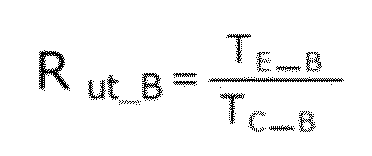

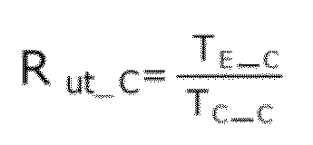
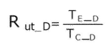
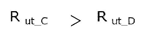
以上のように、実施の形態10に係るヘッドアップディスプレイ100においては、第2レンズ134の負のパワーに上下方向で強弱をつけ、また、第1レンズ133の正のパワーに上下方向で強弱をつけることにより、焦点面Fを傾斜させ、虚像I1,I2を傾斜させる。また、実施の形態10においても、結像位置可変部150に含まれる投射光学系140は、路面Rに対する観察者Dの視点位置の高さを所定の高さとし、俯角を所定の角度とした時、遠視位置P2における虚像I2の主要部の下端を、路面Rの位置以上の高い位置とするように設定されている。また、投射光学系140は、同様に、路面Rに対する観察者Dの視点位置の高さを所定の高さとし、俯角を所定の角度とした時、遠視位置P2における虚像I2の上端I2_uを、下端I2_lの路面Rからの高さよりも、上端I2_uの路面Rからの高さが高くなる位置とするように設定されている。したがって、実施の形態10によれば、遠視位置P2における虚像I2が、路面Rにめり込むことを防止し、観察者Dに違和感を覚えさせることを防ぐことができる。また、本実施の形態によれば、虚像I2の上端I2_uが下端I2_lよりも低くならず、観察者Dに違和感を覚えさせることを防ぐことができる。
また、実施の形態1~10では、ヘッドアップディスプレイ100はダッシュボード210の下方に配置しているが、ダッシュボード210の上方に配置しても良い。
また、上述の実施の形態は、本開示における技術を例示するためのものであるから、特許請求の範囲またはその均等の範囲において種々の変更、置き換え、付加、省略などを行うことができる。
(1)本開示のヘッドアップディスプレイは、車両等の移動体に設置され、画像を虚像として観察者に表示するヘッドアップディスプレイであって、画像を表示する表示デバイスと、画像を拡大して投影する投射光学系と、を含み、虚像の位置を、観察者から遠い遠視位置と、観察者に近い近視位置とに変化させる結像位置可変部を備え、結像位置可変部は、遠視位置において、観察者の視点が位置する視点領域の中心に到達する基準光線の垂直面に対して、虚像の上端を移動体の前方に第2の傾斜角度で傾斜させ、近視位置において、基準光線の垂直面に対して、虚像の上端を移動体の前方に第2の傾斜角度よりも小さい第1の傾斜角度で傾斜させる。
110 表示デバイス
111 表示デバイス
123,133 第1レンズ
124,134 第2レンズ
125 第1ミラー
126 第2ミラー
127 第3ミラー
128 第3レンズ
129 第4レンズ
130 半透過反射ミラー
131 第4ミラー
132 レンズ
140 投射光学系
150 結像位置可変部
200 車両
210 ダッシュボード
220 ウインドシールド
300 視点領域
D 観察者
I 虚像
Lc 基準光線
Lu 上光線
Ll 下光線
P1 近視位置
P2 遠視位置
R 路面
Claims (15)
- 移動体に設置され、画像を虚像として観察者に表示するヘッドアップディスプレイであって、
前記画像を表示する表示デバイスと、前記画像を拡大して投影する投射光学系と、を含み、前記虚像の位置を、前記観察者から遠い遠視位置と、前記観察者に近い近視位置とに変化させる結像位置可変部を備え、
前記結像位置可変部は、前記遠視位置において、前記観察者の視点が位置する視点領域の中心に到達する基準光線の垂直面に対して、前記虚像の上端を前記移動体の前方に第2の傾斜角度で傾斜させ、前記近視位置において、前記基準光線の垂直面に対して、前記虚像の上端を前記移動体の前方に前記第2の傾斜角度よりも小さい第1の傾斜角度で傾斜させる、
ヘッドアップディスプレイ。 - 前記投射光学系は、少なくとも一つの光学素子を備え、
前記光学素子は、前記虚像の下側に到達する光線が通過する側から、前記虚像の上側に到達する光線が通過する側までの間のパワーの変化により、前記遠視位置における前記虚像の下端を、前記移動体の前方の路面の位置以上の高い位置になる前記第2の傾斜角度にする、
請求項1に記載のヘッドアップディスプレイ。 - 前記投射光学系は、少なくとも一つの光学素子を備え、
前記光学素子は、前記虚像の下側に到達する光線が通過する側から、前記虚像の上側に到達する光線が通過する側までの間のパワーの変化により、前記移動体が傾斜する姿勢変動が生じた際であっても、前記遠視位置における前記虚像の下端を、前記移動体の前方の路面の位置以上の高い位置になる前記第1の傾斜角度にする、
請求項1に記載のヘッドアップディスプレイ。 - 前記投射光学系は、複数の光学素子を備え、
前記結像位置可変部は、前記複数の光学素子のうちの少なくともいずれか一つの光学素子と、他の光学素子との前記基準光線方向の間隔を変えることにより、前記虚像の位置を変化させる、
請求項1に記載のヘッドアップディスプレイ。 - 前記結像位置可変部は、前記表示デバイスと、前記投射光学系との前記基準光線方向の間隔を変えることにより、前記虚像の位置を変化させる、
請求項1に記載のヘッドアップディスプレイ。 - 前記投射光学系は、少なくとも一つの光学素子を備え、
前記結像位置可変部は、前記光学素子を、前記表示デバイスからの光路と交差する位置と、交差しない位置とに移動させることにより、前記虚像の位置を変化させる、
請求項1に記載のヘッドアップディスプレイ。 - 前記投射光学系は、複数の光学素子を備え、
前記複数の光学素子のうちの少なくともいずれか一つの光学素子は、前記投射光学系の光路長を変化させる光学素子であり、
前記結像位置可変部は、前記光路長を変化させる光学素子の位置を変化させることにより、前記虚像の位置を変化させる、
請求項1に記載のヘッドアップディスプレイ。 - 前記表示デバイスとして、二つの表示デバイスを備え、
前記二つの表示デバイスは、それぞれの表示デバイスから前記投射光学系までの光路長がそれぞれ異なる位置に配置されており、
前記結像位置可変部は、前記それぞれの表示デバイスを切り替えて前記画像を表示することにより、前記虚像の位置を変化させる、
請求項1に記載のヘッドアップディスプレイ。 - 前記投射光学系は、パワーを変化させることが可能なパワー可変光学素子を備え、
前記結像位置可変部は、前記パワー可変光学素子のパワーを変化させることにより、前記虚像の位置を変化させる、
請求項1に記載のヘッドアップディスプレイ。 - 前記表示デバイスは、前記基準光線に対して、画像表示が傾斜している、
請求項1ないし請求項9のいずれか1項に記載のヘッドアップディスプレイ。 - 前記投射光学系は、少なくとも一つの光学素子を備え、
前記光学素子は、上下方向のパワーが異なっており、焦点面が基準光線に対して傾斜している、
請求項1ないし請求項10のいずれか1項に記載のヘッドアップディスプレイ。 - 前記投射光学系は、少なくとも一つの光学素子を備え、
前記光学素子が負のパワーを有しており、当該光学素子における、前記虚像の下側に到達する光線が通過する側の負のパワーを強くし、前記虚像の上側に到達する光線が通過する側の負のパワーを弱くした、
請求項1ないし請求項11のいずれか1項に記載のヘッドアップディスプレイ。 - 前記投射光学系は、少なくとも一つの光学素子を備え、
前記光学素子が正のパワーを有しており、当該光学素子における、前記虚像の下側に到達する光線が通過する側の正のパワーを弱くし、前記虚像の上側に到達する光線が通過する側の正のパワーを強くした、
請求項1ないし請求項12のいずれか1項に記載のヘッドアップディスプレイ。 - 前記投射光学系は、少なくとも一つの光学素子を備え、
前記光学素子が負のパワーを有しており、当該光学素子における、前記虚像の上側に到達する光線が通過する側のレンズ中心部付近に対する周辺部との厚さの比である1より大きい偏肉比を、前記虚像の上側に到達する光線が通過する側の前記偏肉比に比べて、相対的に大きくした、
請求項1ないし請求項13のいずれか1項に記載のヘッドアップディスプレイ。 - 前記投射光学系は、少なくとも一つの光学素子を備え、
前記光学素子が正のパワーを有しており、当該光学素子における、前記虚像の下側に到達する光線が通過する側のレンズ中心部付近に対する周辺部との厚さの比である偏肉比を、前記虚像の下側に到達する光線が通過する側の前記偏肉比に比べて、相対的に大きくした、
請求項1ないし請求項14のいずれか1項に記載のヘッドアップディスプレイ。
Priority Applications (3)
| Application Number | Priority Date | Filing Date | Title |
|---|---|---|---|
| JP2020535831A JP7203330B2 (ja) | 2018-08-08 | 2019-08-07 | ヘッドアップディスプレイ |
| EP19846182.4A EP3835848B1 (en) | 2018-08-08 | 2019-08-07 | Head-up display |
| US17/126,507 US11604360B2 (en) | 2018-08-08 | 2020-12-18 | Head-up display |
Applications Claiming Priority (2)
| Application Number | Priority Date | Filing Date | Title |
|---|---|---|---|
| JP2018149541 | 2018-08-08 | ||
| JP2018-149541 | 2018-08-08 |
Related Child Applications (1)
| Application Number | Title | Priority Date | Filing Date |
|---|---|---|---|
| US17/126,507 Continuation US11604360B2 (en) | 2018-08-08 | 2020-12-18 | Head-up display |
Publications (1)
| Publication Number | Publication Date |
|---|---|
| WO2020032095A1 true WO2020032095A1 (ja) | 2020-02-13 |
Family
ID=69413750
Family Applications (1)
| Application Number | Title | Priority Date | Filing Date |
|---|---|---|---|
| PCT/JP2019/031092 Ceased WO2020032095A1 (ja) | 2018-08-08 | 2019-08-07 | ヘッドアップディスプレイ |
Country Status (4)
| Country | Link |
|---|---|
| US (1) | US11604360B2 (ja) |
| EP (1) | EP3835848B1 (ja) |
| JP (1) | JP7203330B2 (ja) |
| WO (1) | WO2020032095A1 (ja) |
Cited By (6)
| Publication number | Priority date | Publication date | Assignee | Title |
|---|---|---|---|---|
| JPWO2023187872A1 (ja) * | 2022-03-28 | 2023-10-05 | ||
| EP4227726A4 (en) * | 2020-10-31 | 2023-12-27 | Huawei Technologies Co., Ltd. | HEAD-UP DISPLAY AND HEAD-UP DISPLAY METHODS |
| JP2025503547A (ja) * | 2021-12-30 | 2025-02-04 | フューチュラス テクノロジー カンパニー リミテッド | 表示装置、ヘッドアップディスプレイ及び交通機器 |
| JP2025526586A (ja) * | 2022-07-28 | 2025-08-15 | フューチュラス テクノロジー カンパニー リミテッド | 画像ソース、表示装置、ヘッドアップディスプレイ装置及び交通装置 |
| JP2025528053A (ja) * | 2022-07-28 | 2025-08-26 | フューチュラス テクノロジー カンパニー リミテッド | 表示装置、画像ソース装置、交通デバイス及び表示方法 |
| JP7908709B2 (ja) | 2022-07-28 | 2026-08-20 | フューチュラス テクノロジー カンパニー リミテッド | 表示装置、画像ソース装置、交通デバイス及び表示方法 |
Families Citing this family (2)
| Publication number | Priority date | Publication date | Assignee | Title |
|---|---|---|---|---|
| CN116481777B (zh) * | 2023-05-19 | 2026-01-23 | 福耀玻璃工业集团股份有限公司 | 光学元件检测系统、检测方法及应用 |
| DE102024102232A1 (de) * | 2024-01-26 | 2025-07-31 | Valeo Schalter Und Sensoren Gmbh | Head-up-Display mit Flüssigkristalllinse zur spezifischen Neigung einer Bildebene |
Citations (8)
| Publication number | Priority date | Publication date | Assignee | Title |
|---|---|---|---|---|
| JPH06115381A (ja) | 1992-10-08 | 1994-04-26 | Y N S:Kk | ヘッドアップディスプレイにおける虚像のコントロール方法及び虚像のコントロール装置 |
| JP2009150947A (ja) | 2007-12-19 | 2009-07-09 | Hitachi Ltd | 車両用ヘッドアップディスプレイ装置 |
| JP2016024420A (ja) * | 2014-07-24 | 2016-02-08 | トヨタ自動車株式会社 | 車両用表示装置 |
| JP2016155505A (ja) * | 2015-02-26 | 2016-09-01 | アイシン・エィ・ダブリュ株式会社 | 虚像表示装置 |
| WO2017094427A1 (ja) * | 2015-12-01 | 2017-06-08 | 日本精機株式会社 | ヘッドアップディスプレイ |
| WO2018042898A1 (ja) * | 2016-08-29 | 2018-03-08 | マクセル株式会社 | ヘッドアップディスプレイ装置 |
| WO2018066081A1 (ja) * | 2016-10-04 | 2018-04-12 | マクセル株式会社 | 投影光学系及びヘッドアップディスプレイ装置 |
| JP2018146882A (ja) * | 2017-03-08 | 2018-09-20 | パナソニックIpマネジメント株式会社 | 画像投写装置 |
Family Cites Families (8)
| Publication number | Priority date | Publication date | Assignee | Title |
|---|---|---|---|---|
| WO2010064582A1 (ja) * | 2008-12-04 | 2010-06-10 | コニカミノルタホールディングス株式会社 | 映像表示装置およびヘッドマウントディスプレイ |
| JP6149543B2 (ja) * | 2013-06-28 | 2017-06-21 | アイシン・エィ・ダブリュ株式会社 | ヘッドアップディスプレイ装置 |
| US9928769B2 (en) * | 2015-09-29 | 2018-03-27 | Panasonic Intellectual Property Management Co., Ltd. | Head-up display and vehicle equipped with head-up display |
| JPWO2017090464A1 (ja) * | 2015-11-25 | 2018-09-13 | 日本精機株式会社 | ヘッドアップディスプレイ |
| US10866415B2 (en) * | 2016-02-05 | 2020-12-15 | Maxell, Ltd. | Head-up display apparatus |
| CN109477967A (zh) * | 2016-05-11 | 2019-03-15 | 威瑞股份公司 | 具可变焦平面的抬头显示系统 |
| US10012836B2 (en) * | 2016-05-23 | 2018-07-03 | Lg Electronics Inc. | Head up display for vehicle |
| US10814723B2 (en) * | 2016-10-04 | 2020-10-27 | Maxell, Ltd. | Projection optical system, and head-up display device |
-
2019
- 2019-08-07 JP JP2020535831A patent/JP7203330B2/ja active Active
- 2019-08-07 EP EP19846182.4A patent/EP3835848B1/en active Active
- 2019-08-07 WO PCT/JP2019/031092 patent/WO2020032095A1/ja not_active Ceased
-
2020
- 2020-12-18 US US17/126,507 patent/US11604360B2/en active Active
Patent Citations (8)
| Publication number | Priority date | Publication date | Assignee | Title |
|---|---|---|---|---|
| JPH06115381A (ja) | 1992-10-08 | 1994-04-26 | Y N S:Kk | ヘッドアップディスプレイにおける虚像のコントロール方法及び虚像のコントロール装置 |
| JP2009150947A (ja) | 2007-12-19 | 2009-07-09 | Hitachi Ltd | 車両用ヘッドアップディスプレイ装置 |
| JP2016024420A (ja) * | 2014-07-24 | 2016-02-08 | トヨタ自動車株式会社 | 車両用表示装置 |
| JP2016155505A (ja) * | 2015-02-26 | 2016-09-01 | アイシン・エィ・ダブリュ株式会社 | 虚像表示装置 |
| WO2017094427A1 (ja) * | 2015-12-01 | 2017-06-08 | 日本精機株式会社 | ヘッドアップディスプレイ |
| WO2018042898A1 (ja) * | 2016-08-29 | 2018-03-08 | マクセル株式会社 | ヘッドアップディスプレイ装置 |
| WO2018066081A1 (ja) * | 2016-10-04 | 2018-04-12 | マクセル株式会社 | 投影光学系及びヘッドアップディスプレイ装置 |
| JP2018146882A (ja) * | 2017-03-08 | 2018-09-20 | パナソニックIpマネジメント株式会社 | 画像投写装置 |
Cited By (11)
| Publication number | Priority date | Publication date | Assignee | Title |
|---|---|---|---|---|
| EP4227726A4 (en) * | 2020-10-31 | 2023-12-27 | Huawei Technologies Co., Ltd. | HEAD-UP DISPLAY AND HEAD-UP DISPLAY METHODS |
| US12092819B2 (en) | 2020-10-31 | 2024-09-17 | Huawei Technologies Co., Ltd. | Head-up display and head-up display method |
| JP2025503547A (ja) * | 2021-12-30 | 2025-02-04 | フューチュラス テクノロジー カンパニー リミテッド | 表示装置、ヘッドアップディスプレイ及び交通機器 |
| JP7776066B2 (ja) | 2021-12-30 | 2025-11-26 | フューチュラス テクノロジー カンパニー リミテッド | 表示装置、ヘッドアップディスプレイ及び交通機器 |
| JPWO2023187872A1 (ja) * | 2022-03-28 | 2023-10-05 | ||
| WO2023187872A1 (ja) * | 2022-03-28 | 2023-10-05 | Tdk株式会社 | プロジェクターモジュール及びそれを備えた網膜投影表示装置 |
| JP7884587B2 (ja) | 2022-03-28 | 2026-07-03 | Tdk株式会社 | プロジェクターモジュール及びそれを備えた網膜投影表示装置 |
| JP2025526586A (ja) * | 2022-07-28 | 2025-08-15 | フューチュラス テクノロジー カンパニー リミテッド | 画像ソース、表示装置、ヘッドアップディスプレイ装置及び交通装置 |
| JP2025528053A (ja) * | 2022-07-28 | 2025-08-26 | フューチュラス テクノロジー カンパニー リミテッド | 表示装置、画像ソース装置、交通デバイス及び表示方法 |
| JP7902525B2 (ja) | 2022-07-28 | 2026-08-10 | フューチュラス テクノロジー カンパニー リミテッド | 画像ソース、表示装置、ヘッドアップディスプレイ装置及び交通装置 |
| JP7908709B2 (ja) | 2022-07-28 | 2026-08-20 | フューチュラス テクノロジー カンパニー リミテッド | 表示装置、画像ソース装置、交通デバイス及び表示方法 |
Also Published As
| Publication number | Publication date |
|---|---|
| US11604360B2 (en) | 2023-03-14 |
| JP7203330B2 (ja) | 2023-01-13 |
| JPWO2020032095A1 (ja) | 2021-09-09 |
| EP3835848A1 (en) | 2021-06-16 |
| EP3835848B1 (en) | 2026-03-11 |
| EP3835848A4 (en) | 2021-10-06 |
| US20210103151A1 (en) | 2021-04-08 |
Similar Documents
| Publication | Publication Date | Title |
|---|---|---|
| JP7203330B2 (ja) | ヘッドアップディスプレイ | |
| JP6582245B2 (ja) | ヘッドアップディスプレイ及び車両 | |
| JP6709906B2 (ja) | 画像投写装置 | |
| JP7715889B2 (ja) | ヘッドアップディスプレイ | |
| US11703683B2 (en) | Head-up display and mobile body equipped with head-up display | |
| JP6225341B2 (ja) | ヘッドアップディスプレイおよびヘッドアップディスプレイを搭載した移動体 | |
| JP7162273B2 (ja) | ヘッドアップディスプレイおよびヘッドアップディスプレイを搭載した移動体 | |
| JP7702543B2 (ja) | ヘッドアップディスプレイ | |
| JP6830182B2 (ja) | 画像投写装置 | |
| JPWO2018066062A1 (ja) | 投影光学系、及びヘッドアップディスプレイ装置 | |
| US20180270455A1 (en) | Image display device | |
| US11275241B2 (en) | Head-up display and moving object equipped with head-up display | |
| WO2018186149A1 (ja) | ヘッドアップディスプレイシステム、およびヘッドアップディスプレイシステムを備える移動体 | |
| WO2021002428A1 (ja) | ヘッドアップディスプレイ装置 | |
| US11415800B2 (en) | Head-up display |
Legal Events
| Date | Code | Title | Description |
|---|---|---|---|
| 121 | Ep: the epo has been informed by wipo that ep was designated in this application |
Ref document number: 19846182 Country of ref document: EP Kind code of ref document: A1 |
|
| WWE | Wipo information: entry into national phase |
Ref document number: 2020535831 Country of ref document: JP |
|
| NENP | Non-entry into the national phase |
Ref country code: DE |
|
| ENP | Entry into the national phase |
Ref document number: 2019846182 Country of ref document: EP Effective date: 20210309 |
|
| WWG | Wipo information: grant in national office |
Ref document number: 2019846182 Country of ref document: EP |