WO2020040115A1 - 合わせガラスセット及び合わせガラス構造体 - Google Patents
合わせガラスセット及び合わせガラス構造体 Download PDFInfo
- Publication number
- WO2020040115A1 WO2020040115A1 PCT/JP2019/032372 JP2019032372W WO2020040115A1 WO 2020040115 A1 WO2020040115 A1 WO 2020040115A1 JP 2019032372 W JP2019032372 W JP 2019032372W WO 2020040115 A1 WO2020040115 A1 WO 2020040115A1
- Authority
- WO
- WIPO (PCT)
- Prior art keywords
- intermediate film
- laminated glass
- resin layer
- laminated
- distance
- Prior art date
- Legal status (The legal status is an assumption and is not a legal conclusion. Google has not performed a legal analysis and makes no representation as to the accuracy of the status listed.)
- Ceased
Links
Images











Classifications
-
- B—PERFORMING OPERATIONS; TRANSPORTING
- B32—LAYERED PRODUCTS
- B32B—LAYERED PRODUCTS, i.e. PRODUCTS BUILT-UP OF STRATA OF FLAT OR NON-FLAT, e.g. CELLULAR OR HONEYCOMB, FORM
- B32B17/00—Layered products essentially comprising sheet glass, or glass, slag, or like fibres
- B32B17/06—Layered products essentially comprising sheet glass, or glass, slag, or like fibres comprising glass as the main or only constituent of a layer, next to another layer of a specific material
- B32B17/10—Layered products essentially comprising sheet glass, or glass, slag, or like fibres comprising glass as the main or only constituent of a layer, next to another layer of a specific material of synthetic resin
- B32B17/10005—Layered products essentially comprising sheet glass, or glass, slag, or like fibres comprising glass as the main or only constituent of a layer, next to another layer of a specific material of synthetic resin laminated safety glass or glazing
- B32B17/1055—Layered products essentially comprising sheet glass, or glass, slag, or like fibres comprising glass as the main or only constituent of a layer, next to another layer of a specific material of synthetic resin laminated safety glass or glazing characterized by the resin layer, i.e. interlayer
- B32B17/10651—Layered products essentially comprising sheet glass, or glass, slag, or like fibres comprising glass as the main or only constituent of a layer, next to another layer of a specific material of synthetic resin laminated safety glass or glazing characterized by the resin layer, i.e. interlayer comprising colorants, e.g. dyes or pigments
- B32B17/1066—Layered products essentially comprising sheet glass, or glass, slag, or like fibres comprising glass as the main or only constituent of a layer, next to another layer of a specific material of synthetic resin laminated safety glass or glazing characterized by the resin layer, i.e. interlayer comprising colorants, e.g. dyes or pigments imparting a tint in certain regions only, i.e. shade band
-
- B—PERFORMING OPERATIONS; TRANSPORTING
- B32—LAYERED PRODUCTS
- B32B—LAYERED PRODUCTS, i.e. PRODUCTS BUILT-UP OF STRATA OF FLAT OR NON-FLAT, e.g. CELLULAR OR HONEYCOMB, FORM
- B32B17/00—Layered products essentially comprising sheet glass, or glass, slag, or like fibres
- B32B17/06—Layered products essentially comprising sheet glass, or glass, slag, or like fibres comprising glass as the main or only constituent of a layer, next to another layer of a specific material
- B32B17/10—Layered products essentially comprising sheet glass, or glass, slag, or like fibres comprising glass as the main or only constituent of a layer, next to another layer of a specific material of synthetic resin
- B32B17/10005—Layered products essentially comprising sheet glass, or glass, slag, or like fibres comprising glass as the main or only constituent of a layer, next to another layer of a specific material of synthetic resin laminated safety glass or glazing
- B32B17/10009—Layered products essentially comprising sheet glass, or glass, slag, or like fibres comprising glass as the main or only constituent of a layer, next to another layer of a specific material of synthetic resin laminated safety glass or glazing characterized by the number, the constitution or treatment of glass sheets
- B32B17/10036—Layered products essentially comprising sheet glass, or glass, slag, or like fibres comprising glass as the main or only constituent of a layer, next to another layer of a specific material of synthetic resin laminated safety glass or glazing characterized by the number, the constitution or treatment of glass sheets comprising two outer glass sheets
-
- B—PERFORMING OPERATIONS; TRANSPORTING
- B32—LAYERED PRODUCTS
- B32B—LAYERED PRODUCTS, i.e. PRODUCTS BUILT-UP OF STRATA OF FLAT OR NON-FLAT, e.g. CELLULAR OR HONEYCOMB, FORM
- B32B17/00—Layered products essentially comprising sheet glass, or glass, slag, or like fibres
- B32B17/06—Layered products essentially comprising sheet glass, or glass, slag, or like fibres comprising glass as the main or only constituent of a layer, next to another layer of a specific material
- B32B17/10—Layered products essentially comprising sheet glass, or glass, slag, or like fibres comprising glass as the main or only constituent of a layer, next to another layer of a specific material of synthetic resin
- B32B17/10005—Layered products essentially comprising sheet glass, or glass, slag, or like fibres comprising glass as the main or only constituent of a layer, next to another layer of a specific material of synthetic resin laminated safety glass or glazing
- B32B17/10165—Functional features of the laminated safety glass or glazing
- B32B17/10293—Edge features, e.g. inserts or holes
-
- B—PERFORMING OPERATIONS; TRANSPORTING
- B32—LAYERED PRODUCTS
- B32B—LAYERED PRODUCTS, i.e. PRODUCTS BUILT-UP OF STRATA OF FLAT OR NON-FLAT, e.g. CELLULAR OR HONEYCOMB, FORM
- B32B17/00—Layered products essentially comprising sheet glass, or glass, slag, or like fibres
- B32B17/06—Layered products essentially comprising sheet glass, or glass, slag, or like fibres comprising glass as the main or only constituent of a layer, next to another layer of a specific material
- B32B17/10—Layered products essentially comprising sheet glass, or glass, slag, or like fibres comprising glass as the main or only constituent of a layer, next to another layer of a specific material of synthetic resin
- B32B17/10005—Layered products essentially comprising sheet glass, or glass, slag, or like fibres comprising glass as the main or only constituent of a layer, next to another layer of a specific material of synthetic resin laminated safety glass or glazing
- B32B17/10165—Functional features of the laminated safety glass or glazing
- B32B17/10339—Specific parts of the laminated safety glass or glazing being colored or tinted
- B32B17/10357—Specific parts of the laminated safety glass or glazing being colored or tinted comprising a tinted intermediate film
-
- B—PERFORMING OPERATIONS; TRANSPORTING
- B32—LAYERED PRODUCTS
- B32B—LAYERED PRODUCTS, i.e. PRODUCTS BUILT-UP OF STRATA OF FLAT OR NON-FLAT, e.g. CELLULAR OR HONEYCOMB, FORM
- B32B17/00—Layered products essentially comprising sheet glass, or glass, slag, or like fibres
- B32B17/06—Layered products essentially comprising sheet glass, or glass, slag, or like fibres comprising glass as the main or only constituent of a layer, next to another layer of a specific material
- B32B17/10—Layered products essentially comprising sheet glass, or glass, slag, or like fibres comprising glass as the main or only constituent of a layer, next to another layer of a specific material of synthetic resin
- B32B17/10005—Layered products essentially comprising sheet glass, or glass, slag, or like fibres comprising glass as the main or only constituent of a layer, next to another layer of a specific material of synthetic resin laminated safety glass or glazing
- B32B17/1055—Layered products essentially comprising sheet glass, or glass, slag, or like fibres comprising glass as the main or only constituent of a layer, next to another layer of a specific material of synthetic resin laminated safety glass or glazing characterized by the resin layer, i.e. interlayer
- B32B17/10614—Layered products essentially comprising sheet glass, or glass, slag, or like fibres comprising glass as the main or only constituent of a layer, next to another layer of a specific material of synthetic resin laminated safety glass or glazing characterized by the resin layer, i.e. interlayer comprising particles for purposes other than dyeing
- B32B17/10633—Infrared radiation absorbing or reflecting agents
-
- B—PERFORMING OPERATIONS; TRANSPORTING
- B32—LAYERED PRODUCTS
- B32B—LAYERED PRODUCTS, i.e. PRODUCTS BUILT-UP OF STRATA OF FLAT OR NON-FLAT, e.g. CELLULAR OR HONEYCOMB, FORM
- B32B17/00—Layered products essentially comprising sheet glass, or glass, slag, or like fibres
- B32B17/06—Layered products essentially comprising sheet glass, or glass, slag, or like fibres comprising glass as the main or only constituent of a layer, next to another layer of a specific material
- B32B17/10—Layered products essentially comprising sheet glass, or glass, slag, or like fibres comprising glass as the main or only constituent of a layer, next to another layer of a specific material of synthetic resin
- B32B17/10005—Layered products essentially comprising sheet glass, or glass, slag, or like fibres comprising glass as the main or only constituent of a layer, next to another layer of a specific material of synthetic resin laminated safety glass or glazing
- B32B17/1055—Layered products essentially comprising sheet glass, or glass, slag, or like fibres comprising glass as the main or only constituent of a layer, next to another layer of a specific material of synthetic resin laminated safety glass or glazing characterized by the resin layer, i.e. interlayer
- B32B17/10761—Layered products essentially comprising sheet glass, or glass, slag, or like fibres comprising glass as the main or only constituent of a layer, next to another layer of a specific material of synthetic resin laminated safety glass or glazing characterized by the resin layer, i.e. interlayer containing vinyl acetal
-
- B—PERFORMING OPERATIONS; TRANSPORTING
- B32—LAYERED PRODUCTS
- B32B—LAYERED PRODUCTS, i.e. PRODUCTS BUILT-UP OF STRATA OF FLAT OR NON-FLAT, e.g. CELLULAR OR HONEYCOMB, FORM
- B32B27/00—Layered products comprising a layer of synthetic resin
- B32B27/06—Layered products comprising a layer of synthetic resin as the main or only constituent of a layer, which is next to another layer of the same or of a different material
- B32B27/08—Layered products comprising a layer of synthetic resin as the main or only constituent of a layer, which is next to another layer of the same or of a different material of synthetic resin
-
- B—PERFORMING OPERATIONS; TRANSPORTING
- B32—LAYERED PRODUCTS
- B32B—LAYERED PRODUCTS, i.e. PRODUCTS BUILT-UP OF STRATA OF FLAT OR NON-FLAT, e.g. CELLULAR OR HONEYCOMB, FORM
- B32B27/00—Layered products comprising a layer of synthetic resin
- B32B27/18—Layered products comprising a layer of synthetic resin characterised by the use of special additives
-
- B—PERFORMING OPERATIONS; TRANSPORTING
- B32—LAYERED PRODUCTS
- B32B—LAYERED PRODUCTS, i.e. PRODUCTS BUILT-UP OF STRATA OF FLAT OR NON-FLAT, e.g. CELLULAR OR HONEYCOMB, FORM
- B32B27/00—Layered products comprising a layer of synthetic resin
- B32B27/18—Layered products comprising a layer of synthetic resin characterised by the use of special additives
- B32B27/20—Layered products comprising a layer of synthetic resin characterised by the use of special additives using fillers, pigments, thixotroping agents
-
- B—PERFORMING OPERATIONS; TRANSPORTING
- B32—LAYERED PRODUCTS
- B32B—LAYERED PRODUCTS, i.e. PRODUCTS BUILT-UP OF STRATA OF FLAT OR NON-FLAT, e.g. CELLULAR OR HONEYCOMB, FORM
- B32B3/00—Layered products comprising a layer with external or internal discontinuities or unevennesses, or a layer of non-planar shape; Layered products comprising a layer having particular features of form
- B32B3/02—Layered products comprising a layer with external or internal discontinuities or unevennesses, or a layer of non-planar shape; Layered products comprising a layer having particular features of form characterised by features of form at particular places, e.g. in edge regions
- B32B3/06—Layered products comprising a layer with external or internal discontinuities or unevennesses, or a layer of non-planar shape; Layered products comprising a layer having particular features of form characterised by features of form at particular places, e.g. in edge regions for securing layers together; for attaching the product to another member, e.g. to a support, or to another product, e.g. groove/tongue, interlocking
-
- B—PERFORMING OPERATIONS; TRANSPORTING
- B32—LAYERED PRODUCTS
- B32B—LAYERED PRODUCTS, i.e. PRODUCTS BUILT-UP OF STRATA OF FLAT OR NON-FLAT, e.g. CELLULAR OR HONEYCOMB, FORM
- B32B3/00—Layered products comprising a layer with external or internal discontinuities or unevennesses, or a layer of non-planar shape; Layered products comprising a layer having particular features of form
- B32B3/26—Layered products comprising a layer with external or internal discontinuities or unevennesses, or a layer of non-planar shape; Layered products comprising a layer having particular features of form characterised by a particular shape of the outline of the cross-section of a continuous layer; characterised by a layer with cavities or internal voids ; characterised by an apertured layer
- B32B3/263—Layered products comprising a layer with external or internal discontinuities or unevennesses, or a layer of non-planar shape; Layered products comprising a layer having particular features of form characterised by a particular shape of the outline of the cross-section of a continuous layer; characterised by a layer with cavities or internal voids ; characterised by an apertured layer characterised by a layer having non-uniform thickness
-
- B—PERFORMING OPERATIONS; TRANSPORTING
- B32—LAYERED PRODUCTS
- B32B—LAYERED PRODUCTS, i.e. PRODUCTS BUILT-UP OF STRATA OF FLAT OR NON-FLAT, e.g. CELLULAR OR HONEYCOMB, FORM
- B32B5/00—Layered products characterised by the non- homogeneity or physical structure, i.e. comprising a fibrous, filamentary, particulate or foam layer; Layered products characterised by having a layer differing constitutionally or physically in different parts
- B32B5/14—Layered products characterised by the non- homogeneity or physical structure, i.e. comprising a fibrous, filamentary, particulate or foam layer; Layered products characterised by having a layer differing constitutionally or physically in different parts characterised by a layer differing constitutionally or physically in different parts, e.g. denser near its faces
- B32B5/142—Variation across the area of the layer
-
- B—PERFORMING OPERATIONS; TRANSPORTING
- B32—LAYERED PRODUCTS
- B32B—LAYERED PRODUCTS, i.e. PRODUCTS BUILT-UP OF STRATA OF FLAT OR NON-FLAT, e.g. CELLULAR OR HONEYCOMB, FORM
- B32B5/00—Layered products characterised by the non- homogeneity or physical structure, i.e. comprising a fibrous, filamentary, particulate or foam layer; Layered products characterised by having a layer differing constitutionally or physically in different parts
- B32B5/14—Layered products characterised by the non- homogeneity or physical structure, i.e. comprising a fibrous, filamentary, particulate or foam layer; Layered products characterised by having a layer differing constitutionally or physically in different parts characterised by a layer differing constitutionally or physically in different parts, e.g. denser near its faces
- B32B5/145—Variation across the thickness of the layer
-
- B—PERFORMING OPERATIONS; TRANSPORTING
- B32—LAYERED PRODUCTS
- B32B—LAYERED PRODUCTS, i.e. PRODUCTS BUILT-UP OF STRATA OF FLAT OR NON-FLAT, e.g. CELLULAR OR HONEYCOMB, FORM
- B32B7/00—Layered products characterised by the relation between layers; Layered products characterised by the relative orientation of features between layers, or by the relative values of a measurable parameter between layers, i.e. products comprising layers having different physical, chemical or physicochemical properties; Layered products characterised by the interconnection of layers
- B32B7/02—Physical, chemical or physicochemical properties
- B32B7/023—Optical properties
-
- B—PERFORMING OPERATIONS; TRANSPORTING
- B32—LAYERED PRODUCTS
- B32B—LAYERED PRODUCTS, i.e. PRODUCTS BUILT-UP OF STRATA OF FLAT OR NON-FLAT, e.g. CELLULAR OR HONEYCOMB, FORM
- B32B2250/00—Layers arrangement
- B32B2250/03—3 layers
-
- B—PERFORMING OPERATIONS; TRANSPORTING
- B32—LAYERED PRODUCTS
- B32B—LAYERED PRODUCTS, i.e. PRODUCTS BUILT-UP OF STRATA OF FLAT OR NON-FLAT, e.g. CELLULAR OR HONEYCOMB, FORM
- B32B2250/00—Layers arrangement
- B32B2250/05—5 or more layers
-
- B—PERFORMING OPERATIONS; TRANSPORTING
- B32—LAYERED PRODUCTS
- B32B—LAYERED PRODUCTS, i.e. PRODUCTS BUILT-UP OF STRATA OF FLAT OR NON-FLAT, e.g. CELLULAR OR HONEYCOMB, FORM
- B32B2250/00—Layers arrangement
- B32B2250/40—Symmetrical or sandwich layers, e.g. ABA, ABCBA, ABCCBA
-
- B—PERFORMING OPERATIONS; TRANSPORTING
- B32—LAYERED PRODUCTS
- B32B—LAYERED PRODUCTS, i.e. PRODUCTS BUILT-UP OF STRATA OF FLAT OR NON-FLAT, e.g. CELLULAR OR HONEYCOMB, FORM
- B32B2255/00—Coating on the layer surface
- B32B2255/06—Coating on the layer surface on metal layer
-
- B—PERFORMING OPERATIONS; TRANSPORTING
- B32—LAYERED PRODUCTS
- B32B—LAYERED PRODUCTS, i.e. PRODUCTS BUILT-UP OF STRATA OF FLAT OR NON-FLAT, e.g. CELLULAR OR HONEYCOMB, FORM
- B32B2255/00—Coating on the layer surface
- B32B2255/20—Inorganic coating
-
- B—PERFORMING OPERATIONS; TRANSPORTING
- B32—LAYERED PRODUCTS
- B32B—LAYERED PRODUCTS, i.e. PRODUCTS BUILT-UP OF STRATA OF FLAT OR NON-FLAT, e.g. CELLULAR OR HONEYCOMB, FORM
- B32B2255/00—Coating on the layer surface
- B32B2255/20—Inorganic coating
- B32B2255/205—Metallic coating
-
- B—PERFORMING OPERATIONS; TRANSPORTING
- B32—LAYERED PRODUCTS
- B32B—LAYERED PRODUCTS, i.e. PRODUCTS BUILT-UP OF STRATA OF FLAT OR NON-FLAT, e.g. CELLULAR OR HONEYCOMB, FORM
- B32B2264/00—Composition or properties of particles which form a particulate layer or are present as additives
- B32B2264/02—Synthetic macromolecular particles
- B32B2264/0214—Particles made of materials belonging to B32B27/00
-
- B—PERFORMING OPERATIONS; TRANSPORTING
- B32—LAYERED PRODUCTS
- B32B—LAYERED PRODUCTS, i.e. PRODUCTS BUILT-UP OF STRATA OF FLAT OR NON-FLAT, e.g. CELLULAR OR HONEYCOMB, FORM
- B32B2264/00—Composition or properties of particles which form a particulate layer or are present as additives
- B32B2264/10—Inorganic particles
- B32B2264/101—Glass
-
- B—PERFORMING OPERATIONS; TRANSPORTING
- B32—LAYERED PRODUCTS
- B32B—LAYERED PRODUCTS, i.e. PRODUCTS BUILT-UP OF STRATA OF FLAT OR NON-FLAT, e.g. CELLULAR OR HONEYCOMB, FORM
- B32B2264/00—Composition or properties of particles which form a particulate layer or are present as additives
- B32B2264/10—Inorganic particles
- B32B2264/102—Oxide or hydroxide
-
- B—PERFORMING OPERATIONS; TRANSPORTING
- B32—LAYERED PRODUCTS
- B32B—LAYERED PRODUCTS, i.e. PRODUCTS BUILT-UP OF STRATA OF FLAT OR NON-FLAT, e.g. CELLULAR OR HONEYCOMB, FORM
- B32B2264/00—Composition or properties of particles which form a particulate layer or are present as additives
- B32B2264/10—Inorganic particles
- B32B2264/104—Oxysalt, e.g. carbonate, sulfate, phosphate or nitrate particles
-
- B—PERFORMING OPERATIONS; TRANSPORTING
- B32—LAYERED PRODUCTS
- B32B—LAYERED PRODUCTS, i.e. PRODUCTS BUILT-UP OF STRATA OF FLAT OR NON-FLAT, e.g. CELLULAR OR HONEYCOMB, FORM
- B32B2264/00—Composition or properties of particles which form a particulate layer or are present as additives
- B32B2264/10—Inorganic particles
- B32B2264/107—Ceramic
- B32B2264/108—Carbon, e.g. graphite particles
-
- B—PERFORMING OPERATIONS; TRANSPORTING
- B32—LAYERED PRODUCTS
- B32B—LAYERED PRODUCTS, i.e. PRODUCTS BUILT-UP OF STRATA OF FLAT OR NON-FLAT, e.g. CELLULAR OR HONEYCOMB, FORM
- B32B2264/00—Composition or properties of particles which form a particulate layer or are present as additives
- B32B2264/12—Mixture of at least two particles made of different materials
-
- B—PERFORMING OPERATIONS; TRANSPORTING
- B32—LAYERED PRODUCTS
- B32B—LAYERED PRODUCTS, i.e. PRODUCTS BUILT-UP OF STRATA OF FLAT OR NON-FLAT, e.g. CELLULAR OR HONEYCOMB, FORM
- B32B2264/00—Composition or properties of particles which form a particulate layer or are present as additives
- B32B2264/50—Particles characterised by their position or distribution in a layer
- B32B2264/502—Particles characterised by their position or distribution in a layer distributed in a gradient manner
-
- B—PERFORMING OPERATIONS; TRANSPORTING
- B32—LAYERED PRODUCTS
- B32B—LAYERED PRODUCTS, i.e. PRODUCTS BUILT-UP OF STRATA OF FLAT OR NON-FLAT, e.g. CELLULAR OR HONEYCOMB, FORM
- B32B2270/00—Resin or rubber layer containing a blend of at least two different polymers
-
- B—PERFORMING OPERATIONS; TRANSPORTING
- B32—LAYERED PRODUCTS
- B32B—LAYERED PRODUCTS, i.e. PRODUCTS BUILT-UP OF STRATA OF FLAT OR NON-FLAT, e.g. CELLULAR OR HONEYCOMB, FORM
- B32B2307/00—Properties of the layers or laminate
- B32B2307/10—Properties of the layers or laminate having particular acoustical properties
- B32B2307/102—Insulating
-
- B—PERFORMING OPERATIONS; TRANSPORTING
- B32—LAYERED PRODUCTS
- B32B—LAYERED PRODUCTS, i.e. PRODUCTS BUILT-UP OF STRATA OF FLAT OR NON-FLAT, e.g. CELLULAR OR HONEYCOMB, FORM
- B32B2307/00—Properties of the layers or laminate
- B32B2307/20—Properties of the layers or laminate having particular electrical or magnetic properties, e.g. piezoelectric
- B32B2307/204—Di-electric
-
- B—PERFORMING OPERATIONS; TRANSPORTING
- B32—LAYERED PRODUCTS
- B32B—LAYERED PRODUCTS, i.e. PRODUCTS BUILT-UP OF STRATA OF FLAT OR NON-FLAT, e.g. CELLULAR OR HONEYCOMB, FORM
- B32B2307/00—Properties of the layers or laminate
- B32B2307/30—Properties of the layers or laminate having particular thermal properties
- B32B2307/306—Resistant to heat
-
- B—PERFORMING OPERATIONS; TRANSPORTING
- B32—LAYERED PRODUCTS
- B32B—LAYERED PRODUCTS, i.e. PRODUCTS BUILT-UP OF STRATA OF FLAT OR NON-FLAT, e.g. CELLULAR OR HONEYCOMB, FORM
- B32B2307/00—Properties of the layers or laminate
- B32B2307/40—Properties of the layers or laminate having particular optical properties
- B32B2307/402—Coloured
- B32B2307/4026—Coloured within the layer by addition of a colorant, e.g. pigments, dyes
-
- B—PERFORMING OPERATIONS; TRANSPORTING
- B32—LAYERED PRODUCTS
- B32B—LAYERED PRODUCTS, i.e. PRODUCTS BUILT-UP OF STRATA OF FLAT OR NON-FLAT, e.g. CELLULAR OR HONEYCOMB, FORM
- B32B2307/00—Properties of the layers or laminate
- B32B2307/40—Properties of the layers or laminate having particular optical properties
- B32B2307/412—Transparent
-
- B—PERFORMING OPERATIONS; TRANSPORTING
- B32—LAYERED PRODUCTS
- B32B—LAYERED PRODUCTS, i.e. PRODUCTS BUILT-UP OF STRATA OF FLAT OR NON-FLAT, e.g. CELLULAR OR HONEYCOMB, FORM
- B32B2307/00—Properties of the layers or laminate
- B32B2307/40—Properties of the layers or laminate having particular optical properties
- B32B2307/416—Reflective
-
- B—PERFORMING OPERATIONS; TRANSPORTING
- B32—LAYERED PRODUCTS
- B32B—LAYERED PRODUCTS, i.e. PRODUCTS BUILT-UP OF STRATA OF FLAT OR NON-FLAT, e.g. CELLULAR OR HONEYCOMB, FORM
- B32B2307/00—Properties of the layers or laminate
- B32B2307/40—Properties of the layers or laminate having particular optical properties
- B32B2307/418—Refractive
-
- B—PERFORMING OPERATIONS; TRANSPORTING
- B32—LAYERED PRODUCTS
- B32B—LAYERED PRODUCTS, i.e. PRODUCTS BUILT-UP OF STRATA OF FLAT OR NON-FLAT, e.g. CELLULAR OR HONEYCOMB, FORM
- B32B2307/00—Properties of the layers or laminate
- B32B2307/50—Properties of the layers or laminate having particular mechanical properties
- B32B2307/546—Flexural strength; Flexion stiffness
-
- B—PERFORMING OPERATIONS; TRANSPORTING
- B32—LAYERED PRODUCTS
- B32B—LAYERED PRODUCTS, i.e. PRODUCTS BUILT-UP OF STRATA OF FLAT OR NON-FLAT, e.g. CELLULAR OR HONEYCOMB, FORM
- B32B2307/00—Properties of the layers or laminate
- B32B2307/70—Other properties
- B32B2307/732—Dimensional properties
-
- B—PERFORMING OPERATIONS; TRANSPORTING
- B32—LAYERED PRODUCTS
- B32B—LAYERED PRODUCTS, i.e. PRODUCTS BUILT-UP OF STRATA OF FLAT OR NON-FLAT, e.g. CELLULAR OR HONEYCOMB, FORM
- B32B2307/00—Properties of the layers or laminate
- B32B2307/70—Other properties
- B32B2307/75—Printability
-
- B—PERFORMING OPERATIONS; TRANSPORTING
- B32—LAYERED PRODUCTS
- B32B—LAYERED PRODUCTS, i.e. PRODUCTS BUILT-UP OF STRATA OF FLAT OR NON-FLAT, e.g. CELLULAR OR HONEYCOMB, FORM
- B32B2419/00—Buildings or parts thereof
-
- B—PERFORMING OPERATIONS; TRANSPORTING
- B32—LAYERED PRODUCTS
- B32B—LAYERED PRODUCTS, i.e. PRODUCTS BUILT-UP OF STRATA OF FLAT OR NON-FLAT, e.g. CELLULAR OR HONEYCOMB, FORM
- B32B2605/00—Vehicles
- B32B2605/08—Cars
-
- B—PERFORMING OPERATIONS; TRANSPORTING
- B32—LAYERED PRODUCTS
- B32B—LAYERED PRODUCTS, i.e. PRODUCTS BUILT-UP OF STRATA OF FLAT OR NON-FLAT, e.g. CELLULAR OR HONEYCOMB, FORM
- B32B2605/00—Vehicles
- B32B2605/10—Trains
-
- B—PERFORMING OPERATIONS; TRANSPORTING
- B32—LAYERED PRODUCTS
- B32B—LAYERED PRODUCTS, i.e. PRODUCTS BUILT-UP OF STRATA OF FLAT OR NON-FLAT, e.g. CELLULAR OR HONEYCOMB, FORM
- B32B2605/00—Vehicles
- B32B2605/12—Ships
-
- B—PERFORMING OPERATIONS; TRANSPORTING
- B32—LAYERED PRODUCTS
- B32B—LAYERED PRODUCTS, i.e. PRODUCTS BUILT-UP OF STRATA OF FLAT OR NON-FLAT, e.g. CELLULAR OR HONEYCOMB, FORM
- B32B2605/00—Vehicles
- B32B2605/18—Aircraft
Definitions
- the present invention relates to a laminated glass set provided with an interlayer film for laminated glass having a gradation pattern.
- the present invention also relates to a laminated glass structure using the laminated glass set.
- Laminated glass in which an interlayer film for laminated glass is sandwiched between a pair of glass plates is known.
- This laminated glass is widely used for automobiles, railway vehicles, aircraft, ships, buildings, and the like.
- laminated glass having privacy protection properties As laminated glass for buildings.
- a laminated glass having privacy protection properties for example, light can be transmitted, but there is an area where a person or an object located behind the laminated glass cannot be seen.
- Patent Literature 1 discloses a laminated glass using a multilayer interlayer having an opaque layer.
- privacy protection is realized by the opaque layer that makes a person or an object located behind the laminated glass invisible.
- Patent Document 1 has the same color on the entire surface of the glass, and thus has a problem of low appearance design.
- Patent Documents 2 and 3 below disclose a laminated glass using an intermediate film having a gradation pattern.
- Interlayer films as described in Patent Documents 2 and 3 are often formed by extrusion molding.
- the extruded intermediate film is long and has a length direction and a width direction.
- a gradation pattern with a changed color tone is provided in a direction connecting one end and the other end in the width direction.
- the extruded intermediate film may be wound into a roll before being manufactured as a laminated glass to form a roll.
- the intermediate film is cut at predetermined intervals in the length direction. Then, the plurality of cut intermediate films are respectively disposed between the two glass plates, and a plurality of laminated glasses are manufactured.
- the present inventors have conducted intensive studies and found that, in the conventional intermediate film, the width of the region provided with the gradation pattern varies in the length direction of the intermediate film. For this reason, the present inventors have found that, in a plurality of laminated glasses manufactured using a plurality of cut interlayer films, the width of a region provided with a gradation pattern varies.
- An object of the present invention is to provide a laminated glass set which is a plurality of laminated glasses and has excellent appearance and design.
- each of the plurality of laminated glasses includes a first laminated glass member, a second laminated glass member, and the first laminated glass member.
- an intermediate film portion disposed between the second laminated glass member and the intermediate film portion, the intermediate film portion has one end and the other end on the side opposite to the one end, and the intermediate film portion is , Having a colored portion, the colored portion has a gradation portion in which the visible light transmittance increases from the one end side of the intermediate film portion toward the other end side, the gradation portion, the intermediate film portion Constitutes the tip of the coloring portion on the other end side, and from the one end of the intermediate film portion to the tip of the coloring portion on the other end side of the intermediate film portion in each of the plurality of laminated glasses.
- the X min is 0.6 m or more.
- a tip of the coloring portion on the one end side of the intermediate film portion reaches the one end of the intermediate film portion.
- the Y min is 0.6 m or more.
- a distance Z of the gradation portion in a direction connecting the one end and the other end of the intermediate film portion is measured, and a distance Z is measured.
- the maximum value Z max, the minimum value Z min of the distance Z, the mean value of the distance Z when the Z ave, satisfies the following formula (3).
- the intermediate film portion includes a first resin layer and a second resin layer, and a first resin layer is provided on a first surface side of the second resin layer.
- a resin layer is disposed, the second resin layer contains a coloring agent, and the colored portion is formed by the second resin layer.
- the colorant includes calcium carbonate particles.
- the first resin layer is arranged on a second surface of the second resin layer opposite to the first surface.
- the colored portion has a dark portion in which visible light transmittance is uniform from the one end side of the intermediate film portion toward the other end side, In the intermediate film portion, the dark color portion is located closer to the one end of the intermediate film portion than the gradation portion.
- a laminated glass structure including the above-described laminated glass set and a connecting member that connects a plurality of the laminated glasses in the laminated glass set.
- the laminated glass set according to the present invention is a set of a plurality of laminated glasses.
- each of the plurality of laminated glasses includes a first laminated glass member, a second laminated glass member, the first laminated glass member, and the second laminated glass member. And an intermediate film part disposed between the two.
- the intermediate film portion has one end and the other end opposite to the one end.
- the intermediate film portion has a colored portion.
- the colored portion has a gradation portion in which visible light transmittance increases from the one end side of the intermediate film portion toward the other end side, and the gradation portion includes the intermediate portion. It constitutes the tip of the colored part on the other end side of the film part.
- a distance X from the one end of the intermediate film portion to the tip of the colored portion on the other end side of the intermediate film portion is measured, and the maximum value of the distance X is X max , the distance X Is the minimum value of X min and the average value of the distance X is X ave .
- a distance Y of the colored portion in a direction connecting the one end and the other end of the intermediate film portion is measured, and a maximum value of the distance Y is Y max , and a minimum value of the distance Y is Y
- the average value of min and the distance Y is defined as Y ave .
- the above expression (1) is satisfied or the above expression (2) is satisfied. Since the laminated glass set according to the present invention has the above-described configuration, it is excellent in external design.
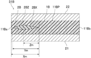
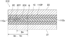
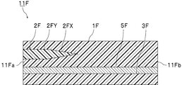
- FIG. 1 is a cross-sectional view schematically showing a laminated glass in the laminated glass set according to the first embodiment of the present invention.
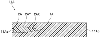
- FIG. 2 is a sectional view schematically showing an intermediate film used to obtain the laminated glass shown in FIG.
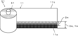
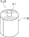
- FIG. 3 is a perspective view schematically showing a roll body on which the intermediate film shown in FIG. 2 is wound.
- FIG. 4 is a perspective view schematically showing a state where the roll body around which the intermediate film shown in FIG. 2 is wound is partially unfolded.
- FIG. 5 is a cross-sectional view schematically showing a laminated glass in the laminated glass set according to the second embodiment of the present invention.
- FIG. 6 is a cross-sectional view schematically showing an intermediate film used to obtain the laminated glass shown in FIG. FIG.
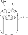
- FIG. 7 is a perspective view schematically showing a roll body on which the intermediate film shown in FIG. 6 is wound.
- FIG. 8 is a perspective view schematically showing a state where the roll body around which the intermediate film shown in FIG. 6 is wound is partially unfolded.
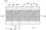
- FIG. 9 is a cross-sectional view schematically illustrating a laminated glass in the laminated glass set according to the third embodiment of the present invention.
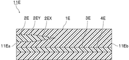
- FIG. 10 is a cross-sectional view schematically showing an intermediate film used to obtain the laminated glass shown in FIG.
- FIG. 11 is a perspective view schematically showing a roll body on which the intermediate film shown in FIG. 10 is wound.
- FIG. 12 is a perspective view schematically showing a state where the roll body around which the intermediate film shown in FIG. 10 is wound is partially unfolded.
- FIG. 13 is a cross-sectional view schematically illustrating a laminated glass in the laminated glass set according to the fourth embodiment of the present invention.
- FIG. 14 is a sectional view schematically showing an intermediate film used to obtain the laminated glass shown in FIG.
- FIG. 15 is a cross-sectional view schematically showing a laminated glass in the laminated glass set according to the fifth embodiment of the present invention.
- FIG. 16 is a sectional view schematically showing an intermediate film used to obtain the laminated glass shown in FIG.
- FIG. 17 is a cross-sectional view schematically illustrating a laminated glass in the laminated glass set according to the sixth embodiment of the present invention.
- FIG. 18 is a cross-sectional view schematically showing an intermediate film used to obtain the laminated glass shown in FIG. FIG.
- FIG. 19 is a cross-sectional view schematically illustrating a laminated glass in the laminated glass set according to the seventh embodiment of the present invention.
- FIG. 20 is a sectional view schematically showing an intermediate film used to obtain the laminated glass shown in FIG.
- FIG. 21 is a cross-sectional view schematically illustrating a laminated glass in the laminated glass set according to the eighth embodiment of the present invention.
- FIG. 22 is a sectional view schematically showing an intermediate film used to obtain the laminated glass shown in FIG.
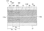
- FIG. 23 is a front view illustrating a laminated glass set including a plurality of laminated glasses illustrated in FIG. 1.
- FIG. 24 is a front view showing a first example of a laminated glass structure using the laminated glass set shown in FIG.
- FIG. 25 is a front view showing a second example of a laminated glass structure using the laminated glass set shown in FIG.
- FIG. 26 is a front view showing a laminated glass structure using a conventional laminated glass set.
- the laminated glass set according to the present invention is a set of a plurality of laminated glasses.
- the laminated glass of one set of the laminated glass corresponds to one laminated glass of a laminated glass structure described later.
- each of the plurality of laminated glasses includes a first laminated glass member, a second laminated glass member, the first laminated glass member, and the second laminated glass member. And an intermediate film part disposed between the two.
- the intermediate film portion has one end and the other end opposite to the one end.
- the one end and the other end are opposite end portions of the intermediate film portion.
- the intermediate film portion has a colored portion.
- the coloring portion extends from the one end side of the intermediate film portion toward the other end side.
- the colored portion has a gradation portion in which visible light transmittance increases from the one end side of the intermediate film portion toward the other end side.
- the gradation portion is a portion where the visible light transmittance increases from the one end side of the intermediate film portion toward the other end side. Due to the change in the visible light transmittance, the color tone of the gradation portion changes. For example, in the gradation portion, the color tone decreases from the one end side of the intermediate film portion toward the other end side.
- the gradation portion constitutes a tip of the coloring portion on the other end side of the intermediate film portion.
- the tip of the portion where the visible light transmittance increases from the one end to the other end of the intermediate film portion is the tip of the gradation portion.
- a distance X from the one end of the intermediate film to the tip of the colored portion at the other end of the intermediate film is measured.
- the maximum value of the distance X is X max
- the minimum value of the distance X is X min
- the average value of the distance X is X ave .
- the laminated glass set according to the present invention preferably satisfies the following expression (1). That is, in the laminated glass set according to the present invention, the ratio of the absolute value of the difference between X max and X min to X ave is preferably 0.1 or less.
- a distance Y between the colored portions in a direction connecting the one end and the other end of the intermediate film portion is measured.
- the maximum value Y max of the distance Y, the minimum value Y min of the distance Y, the average value of the distance Y and Y ave is measured.
- the laminated glass set according to the present invention preferably satisfies the following expression (2). That is, in the laminated glass set according to the present invention, the ratio of the absolute value of the difference between Y max and Y min to Y ave is preferably 0.1 or less.
- the laminated glass set according to the present invention may satisfy Formula (1), may satisfy Formula (2), and satisfies both Formula (1) and Formula (2). You may.
- the laminated glass set according to the present invention is provided with the above-described configuration, and thus has excellent appearance and design. For example, when a plurality of laminated glasses are arranged, the colored portions can be aligned, and the appearance and design are improved.
- the laminated glass set preferably satisfies both the above formulas (1) and (2).
- a distance Z between the gradation portions in a direction connecting the one end and the other end of the intermediate film portion is measured.
- the laminated glass set according to the present invention the maximum value Z max of the distance Z, the minimum value Z min of the distance Z, the mean value of the distance Z and Z ave.
- the laminated glass set according to the present invention preferably satisfies the following expression (3).
- the absolute value of the difference between Z max and Z min, it is preferable ratio Z ave is 0.1 or less. In this case, the appearance design can be further enhanced.
- the distance X, the distance Y, and the distance Z are specifically measured in the following order of 1) and 2).
- Tv The visible light transmittance
- a spectrophotometer for example, “U-4100” manufactured by Hitachi High-Technologies Corporation.
- both ends of the intermediate film portion in a direction perpendicular to both a direction connecting the one end and the other end of the intermediate film portion and a thickness direction of the intermediate film portion are respectively a second end and a second other end.
- the measurement of the visible light transmittance is performed for one laminated glass, in a region existing between the second end and a position 5 cm from the second end toward the inside of the laminated glass, and 2 is performed in a region existing between the other end of No. 2 and the position 5 cm from the second other end toward the inside of the laminated glass.
- these two regions may be referred to as measurement regions.
- two measurements of visible light transmittance are obtained for one piece of laminated glass.
- the laminated glass is placed on the optical path between the light source and the integrating sphere and at a position 13 cm away from the integrating sphere so that it is parallel to the normal of the optical axis so that only the parallel light transmitted through the laminated glass is received by the integrating sphere. Then, the spectral transmittance is measured. The visible light transmittance of the laminated glass is calculated from the obtained spectral transmittance. Similarly, the visible light transmittance is calculated for all the laminated glasses. In this way, the visible light transmittance of the laminated glass is measured along the direction connecting one end and the other end of the intermediate film portion in the laminated glass, and the maximum visible light transmittance in each measurement region is measured for each of the laminated glasses.
- Tv max The value (Tv max ) and the minimum value (Tv min ) are obtained. Therefore, two Tv max and two Tv min are obtained for one laminated glass.
- the measurement conditions were as follows: scan speed: 300 nm / min, slit width: 8 nm, and other measurement conditions conformed to JIS R3106: 1998.
- each measurement area of each laminated glass is divided into the following areas based on the measurement result of the visible light transmittance. For one piece of laminated glass, two distances X, two distances Y, and two distances X are obtained.
- Light-colored portion a region where Tv exceeds (0.1 Tv min +0.9 Tv max ) and is equal to or less than Tv max.
- Gradation portion (to be described as a first gradation portion to be distinguished from a second gradation portion described later).
- Tv is (0.9Tv min + 0.1Tv max) above, (0.1Tv min + 0.9Tv max) or less, and Tv is increased toward the other end from one end of the intermediate film region the second gradation portion: Tv is (0.9Tv min + 0.1Tv max) above, (0.1Tv min + 0.9Tv max) or less and is Tv toward the one end side from the other end side of the intermediate layer portion It becomes higher regions dark color: Tv is Tv min or more, (0.9Tv min + 0.1Tv max) less than whose area colored portion: dark color portion and gradation portion Area the combined
- Distance X distance from one end of the intermediate film portion to the tip of the colored portion on the other end side of the intermediate film portion. More specifically, the distance X is “the distance from one end of the intermediate film portion to the boundary between the light-colored portion and the gradation portion”.
- Distance Y Distance of the colored portion in the direction connecting one end and the other end of the intermediate film portion.
- the distance Y is equal to one end of the intermediate film part. This is the distance between the colored portions including the two gradation portions in the direction connecting the other end.
- Distance Z distance of the gradation part in the direction connecting one end and the other end of the intermediate film part
- the distance X, the distance Y, and the distance Z of each measurement region of all the laminated glasses constituting the laminated glass set are obtained. Therefore, the distance X, the distance Y, and the distance Z are obtained for twice the number of laminated glasses constituting the laminated glass set. From the obtained distances X, a maximum value X max of the distance X, a minimum value X min of the distance X, and an average value X ave of the distance X are obtained. From the obtained distances Y, a maximum value Y max of the distance Y, a minimum value Y min of the distance Y, and an average value Y ave of the distance Y are obtained. From the obtained distances Z, a maximum value Z max of the distance Z, a minimum value Z min of the distance Z, and an average value Z ave of the distance Z are obtained.
- the laminated glass structure When measuring the visible light transmittance and the distance X, the distance Y and the distance Z, the laminated glass structure may be removed from the laminated glass structure, and the resulting laminated glass may be measured. May be measured for the laminated glass of the laminated glass set used for the production of the above.
- the distance X may be equal to the distance Y in one laminated glass.
- the intermediate film portion includes the coloring portion as a first coloring portion, and has a second coloring portion having a gradation portion in which the visible light transmittance increases from the other end to the one end in the width direction of the intermediate film. You may have.
- the intermediate film section may have a single-layer structure or a structure having two or more layers.
- the intermediate film portion may have a two-layer structure, may have a three-layer structure, or may have a four-layer structure. Further, when the intermediate film portion has a structure of two or more layers, the entire intermediate film portion may not have a structure of two or more layers in a direction orthogonal to the thickness direction of the intermediate film portion. The part may partially have a one-layer structure.
- the intermediate film part includes a first resin layer and a second resin layer, and the first resin layer is disposed on the first surface side of the second resin layer.
- the second resin layer preferably contains a coloring agent.
- the colored portion is preferably formed by the second resin layer.
- the first resin layer is disposed on a second surface side of the second resin layer opposite to the first surface side. Is preferred. From the viewpoint of suppressing color tone deterioration, it is preferable that the second resin layer is embedded in the first resin layer.
- the second resin layer preferably contains a coloring agent, and the second resin layer preferably forms the colored portion.
- the first resin layer is disposed on the first surface side of the second resin layer, and the first resin layer is disposed on the second resin layer. It is preferable that the first resin layer is disposed on the second surface side. From the viewpoint of suppressing color tone deterioration, it is preferable that the second resin layer is disposed between the first resin layers.
- the second resin layer preferably contains a coloring agent, and the second resin layer preferably forms the colored portion.
- the intermediate film portion includes a first resin layer, a second resin layer, and a third resin layer, and a first resin layer is disposed on a first surface side of the second resin layer.
- a third resin layer is disposed on a second surface side of the second resin layer opposite to the first surface.
- the second resin layer preferably contains a coloring agent, and the second resin layer preferably forms the colored portion.
- the intermediate film portion includes a first resin layer, a second resin layer, a third resin layer, and the fourth resin layer, wherein the second resin layer is provided in the first resin layer.
- the third resin layer is disposed on the first surface side of the first resin layer
- the third resin layer is disposed on the surface side of the third resin layer opposite to the first resin layer.
- the fourth resin layer is disposed.
- the second resin layer preferably contains a coloring agent
- the second resin layer preferably forms the colored portion.
- the first resin layer and the third resin layer may be directly laminated, and a function to be described later is provided between the first resin layer and the third resin layer.
- a film or the like may be provided.
- the intermediate film portion includes a first resin layer, a second resin layer, a third resin layer, and the fourth resin layer, and the second resin layer is provided in the first resin layer.
- the fourth resin layer is embedded in the third resin layer, and the third resin layer and the third resin layer are formed on the first surface side of the first resin layer. It is also preferable that the fourth resin layer is disposed.
- the second resin layer and the fourth resin layer contain a coloring agent, and the colored portion is formed by the second resin layer and the fourth resin layer.
- the first resin layer and the third resin layer may be directly laminated, and a function to be described later is provided between the first resin layer and the third resin layer. A film or the like may be provided.
- the first resin layer, the second resin layer, the third resin layer, and the fourth resin layer may have the same composition, or may have different compositions. .
- the third resin layer is not particularly limited, but may be a resin layer having excellent sound insulation.
- the third resin layer may be a sound insulation layer.
- the third resin layer is a sound insulating layer, the sound insulating property and appearance design of the laminated glass can be improved.
- the width of the colored portion in the obtained intermediate film is likely to fluctuate.
- it is necessary to precisely control the fluctuation of the suction pressure during manufacturing.
- the intermediate film portion can be obtained by cutting the intermediate film into a predetermined size.
- the intermediate film preferably has an MD direction and a TD direction.
- the intermediate film is obtained, for example, by melt extrusion.
- the MD direction is a flow direction of the intermediate film at the time of manufacturing the intermediate film.
- the TD direction is a direction perpendicular to the flow direction of the intermediate film during the production of the intermediate film, and is a direction perpendicular to the thickness direction of the intermediate film.
- the length direction of the intermediate film is usually the MD direction.
- the width direction of the intermediate film is usually the TD direction.
- the length direction and the width direction of the interlayer mean the direction in the interlayer before the production of the laminated glass, and the direction in the interlayer before cutting.
- the length direction of the cut intermediate film (cut) may be shorter than the width direction of the cut intermediate film (cut).
- the length direction of the interlayer film before cutting may correspond to the length direction of the laminated glass, or may correspond to the width direction of the laminated glass.
- the width direction of the interlayer film before cutting may correspond to the width direction of the laminated glass, or may correspond to the length direction of the laminated glass.
- a direction connecting the one end and the other end of the intermediate film portion corresponds to a width direction of the intermediate film.
- the intermediate film preferably has a length (L) of 30 m or more in the length direction.
- the length (L) is preferably 50 m or more, more preferably 100 m or more, still more preferably 150 m or more, further preferably 250 m or more, and even more. It is preferably at least 500 m, most preferably at least 1000 m. From the viewpoint of further improving the handleability of the interlayer, the length (L) may be 2000 m or less, 1000 m or less, or 600 m or less.
- the width (W) (dimension in the width direction) is usually smaller than the length (L) (dimension in the length direction).
- the width (W) is preferably 0.8 m or more, more preferably 1.0 m or more, still more preferably 1.2 m or more, preferably 2.0 m or less. It is more preferably 1.8 m or less, still more preferably 1.5 m or less.
- the ratio (length (L) / width (W)) of the length (L) to the width (W) is preferably 100 or more, more preferably 200.
- the above is more preferably 300 or more, preferably 2000 or less, more preferably 1000 or less, and further preferably 500 or less.
- ) / X ave is preferably 0.1 or less, more preferably 0.09 or less, and still more preferably 0.1 or less. 07 or less, more preferably 0.05 or less, particularly preferably 0.03 or less, and most preferably 0.01 or less.
- is preferably 80 mm or less, more preferably 16 mm or less, and still more preferably 10 mm or less.
- X min is preferably at least 0.1 m, more preferably at least 0.3 m, even more preferably at least 0.6 m, further preferably at least 0.8 m, particularly preferably at least 1.0 m, most preferably at least 1. 5 m or more.
- X min is equal to or larger than the lower limit, privacy protection can be ensured in a large area. If the colored portion is long, the length of the colored portion tends to vary. However, in the present invention, since the variation in the length of the colored portion is controlled with high accuracy, the appearance design of the laminated glass and the laminated glass set can be improved.
- Ratio width (W) of the intermediate layer portion of the X min may be 0.9 or less, it may be 0.8 or less, It may be 0.7 or less, 0.6 or less, 0.5 or less, 0.3 or less, or 0.1 or less.
- ) / Y ave is preferably 0.1 or less, more preferably 0.09 or less, and still more preferably 0.1 or less. 07 or less, more preferably 0.05 or less, particularly preferably 0.03 or less, and most preferably 0.01 or less.
- is preferably 80 mm or less, more preferably 16 mm or less, and still more preferably 10 mm or less.
- Y min is preferably at least 0.1 m, more preferably at least 0.3 m, still more preferably at least 0.6 m, further preferably at least 0.8 m, particularly preferably at least 1.0 m, most preferably at least 1. 5 m or more.
- Y min is equal to or larger than the lower limit, privacy protection can be ensured in a large area. If the colored portion is long, the length of the colored portion tends to vary. However, in the present invention, since the variation in the length of the colored portion is controlled with high accuracy, the appearance and design of the laminated glass set can be enhanced.
- Ratio width (W) of the intermediate layer portion of the Y min may be 0.9 or less, it may be 0.8 or less, It may be 0.7 or less, 0.6 or less, 0.5 or less, 0.3 or less, or 0.1 or less.
- ) / Z ave is preferably 0.1 or less, more preferably 0.07 or less, and further preferably 0.05 or less. It is particularly preferably at most 0.02, most preferably at most 0.01.
- the above-mentioned Z min is preferably at least 0.001 m, more preferably at least 0.01 m, still more preferably at least 0.03 m, further preferably at least 0.1 m, still more preferably at least 0.3 m, particularly preferably at least 0.3 m. 0.5 m or more, most preferably 1 m or more.
- the Zmin is equal to or more than the lower limit, a gradation pattern is formed in a large area, and the appearance and design can be further improved.
- the Z ratio the intermediate layer portion of the width (W) of min may be 0.9 or less, may be 0.5 or less, 0 0.3 or less, 0.1 or less, or 0.05 or less.
- the method of setting the extrusion conditions to a preferable range includes a method of controlling extrusion conditions with high accuracy when extruding an intermediate film.
- the extrusion conditions are controlled to a certain degree of precision.
- a fluctuation in the width direction of a colored portion due to a short period of vibration of the extrusion pressure during extrusion from a mold is detected.
- the fluctuation of the width of the colored portion in a short cycle can be controlled to some extent.
- the present inventors cannot detect a variation in the width direction of the colored portion due to the vibration of the extrusion pressure in a long cycle in the conventional method of manufacturing an interlayer film, and as a result, the Variation was found to be uncontrolled.
- the method for controlling the extrusion conditions with high precision when extruding the interlayer film according to the present invention is specifically the following method.
- a first resin composition for mainly forming a light-colored portion is prepared. Also, a first extruder for kneading and extruding the first resin composition is prepared. Also, a second resin composition, which is a composition mainly for forming a colored portion and contains a colorant, is prepared. Also, a second extruder for kneading and extruding the second resin composition is prepared.
- the first resin composition extruded from the first extruder and the second resin composition extruded from the second extruder are joined and laminated using a feed block. It is preferable to include a step of molding by extruding from a mold.
- the flow rate from each extruder at the time of merging varies, so that the thickness and width of the first resin layer formed by the first resin composition, and The thickness and width of the second resin layer formed by the second resin composition fluctuate, and as a result, the width of the colored portion in the intermediate film extruded from the mold tends to fluctuate.
- variation in the extrusion amount of the first resin composition tends to cause variation in the width of the colored portion. Therefore, it is important to suppress the vibration of the extrusion pressure.
- the present inventors set the difference between the maximum value and the minimum value of the suction pressure for 180 seconds to be equal to or less than a fixed value, so that the fluctuation in the width of the colored portion due to the fluctuation of the discharge pressure in a long cycle can be reduced. It was also found that the intermediate film according to the present invention can be produced. In addition, the present inventors have set up two gear pumps in series, and can more effectively suppress the variation in the width of the colored portion by reducing the variation in suction pressure of the gear pump installed on the downstream side. Was found.
- the gradation portion can be manufactured by the following method or the like.
- the gradation portion is, for example, a portion where the thickness of the second resin layer is reduced from the one end side of the intermediate film portion to the other end side, or the other portion from the one end side of the intermediate film portion.
- the gradation portion is a portion where the thickness of the second resin layer is reduced from the one end side to the other end side of the intermediate film portion. preferable.
- the coloring portion reaches the one end of the intermediate film portion. That is, it is preferable that the tip of the colored portion on the one end side of the intermediate film portion reaches the one end of the intermediate film portion.
- the colored part does not have to reach the one end of the intermediate film part.
- the colored portion does not reach the other end of the intermediate film portion, on the other end side of the intermediate film portion, appropriately increases the visible light transmittance of the laminated glass, or through the laminated glass. Visibility can be improved.
- the colored portion may have the dark portion from the one end side of the intermediate film portion to the other end side.
- the dark portion is located closer to the one end of the intermediate film portion than the gradation portion. It is preferable that the visible light transmittance of the dark color portion is uniform. It is preferable that the colored portion has a dark color portion having a uniform visible light transmittance from the one end side to the other end side of the intermediate film portion.
- the portion where the visible light transmittance increases from the one end side to the other end side of the intermediate film portion is referred to as a first gradation portion.
- the colored portion may have a second gradation portion that is a portion where the visible light transmittance increases from the other end side of the intermediate film portion toward the one end side.
- the second gradation part is located on the one end side of the intermediate film part with respect to the first gradation part.
- the colored portion may have a dark portion between the first gradation portion and the second gradation portion, from the one end side of the intermediate film portion to the other end side.
- the intermediate film part may have the light-colored part.
- the light-colored portion may include a coloring agent, or may not include a coloring agent.
- the light-colored portion may be a part of the first resin layer or a part of the second resin layer containing a coloring agent.
- the laminated glass preferably has a portion having a visible light transmittance of 10% or less, more preferably has a portion having a visible light transmittance of 5% or less, and has a visible light transmittance of 1% or less. It is more preferred to have a portion.
- the portion where the visible light transmittance is equal to or less than the upper limit may be the dark portion or a part of the gradation portion. When there is a portion where the visible light transmittance is equal to or less than the upper limit, privacy protection can be favorably imparted to the laminated glass set.
- the laminated glass preferably has a portion having a visible light transmittance of 20% or more, more preferably has a portion having a visible light transmittance of 40% or more, and has a visible light transmittance of 60% or more. It is more preferred to have a portion, and most preferably to have a portion having a visible light transmittance of 70% or more.
- the portion where the visible light transmittance is equal to or higher than the lower limit may be the dark color portion, the light color portion, or a part of the gradation portion. When there is a portion where the visible light transmittance is equal to or more than the lower limit, transparency can be favorably imparted to the laminated glass set.
- the visible light transmittance means the visible light transmittance of the laminated glass at a wavelength of 380 nm to 780 nm.
- the visible light transmittance can be measured using a spectrophotometer (for example, “U-4100” manufactured by Hitachi High-Technologies Corporation) in accordance with JIS R3106: 1998.
- the area of the portion where the colored portion exists is preferably 5% or more in 100% of the total area of the intermediate film portion. , More preferably 10% or more, still more preferably 15% or more, and still more preferably 20% or more.
- the area of the portion where the colored portion exists may be 30% or more, or may be 40% or more, in 100% of the total area of the intermediate film portion. It may be 50% or more.
- the area of the portion where the colored portion is present may be 90% or less, or may be 80% or less, based on 100% of the total area of the intermediate film portion.
- the area of the portion where the visible light transmittance is 60% or less in the total area of 100% of the laminated glass is preferably 5%. % Or more, more preferably 10% or more, still more preferably 15% or more, and still more preferably 20% or more.
- the area of the portion where the visible light transmittance is 60% or less in the total area of 100% of the laminated glass may be 30% or more, or 40% or more. It may be 50% or more.
- the area of the portion where the visible light transmittance is 60% or less may be 90% or less or 80% or less in the entire area of the laminated glass 100%. It may be 70% or less, 60% or less, or 50% or less.
- the area of the portion where the visible light transmittance is 60% or less has a visible light transmittance of 60% or less with respect to the distance from one end to the other end of the intermediate film portion in two measurement regions of the laminated glass. The ratio of the distance of the region may be obtained and the average value thereof may be used.
- Area (%) of the portion where the visible light transmittance is 60% or less in the measurement region (distance of the region where the visible light transmittance is 60% or less) / (distance from one end of the intermediate film to the other end) ⁇ 100 May be obtained in two measurement regions, and the average value may be regarded as the area of the portion where the visible light transmittance is 60% or less in the total area of 100% of the intermediate film portion.
- the area of the portion where the visible light transmittance is 50% or less in the total area of 100% of the laminated glass is preferably 5%. % Or more, more preferably 10% or more, still more preferably 15% or more, and still more preferably 20% or more.
- the area of the portion where the visible light transmittance is 60% or less may be 30% or more or 40% or more in the entire area of 100% of the laminated glass. It may be 50% or more.
- the area of the portion where the visible light transmittance is 50% or less may be 90% or less or 80% or less in the entire area of the laminated glass 100%. It may be 70% or less, 60% or less, or 50% or less.
- the area of the portion where the visible light transmittance is 40% or less in the total area of 100% of the laminated glass is preferably 5%. % Or more, more preferably 10% or more, still more preferably 15% or more, and still more preferably 20% or more.
- the area of the portion where the visible light transmittance is 60% or less in the total area of 100% of the laminated glass may be 30% or more, or 40% or more. It may be 50% or more.
- the area of the portion where the visible light transmittance is 40% or less in the entire area of 100% of the laminated glass may be 90% or less, or may be 80% or less. It may be 70% or less, 60% or less, or 50% or less.
- the area of the portion where the visible light transmittance is 50% or less and the area where the visible light transmittance is 40% or less are the same as the area of the portion where the visible light transmittance is 60% or less.
- the distance may be calculated from the distance between the region where the transmittance is 50% or less, the region where the visible light transmittance is 40% or less, and the distance from one end to the other end of the intermediate film.
- the laminated glass can be used for partitions, automobiles, railway vehicles, aircraft, ships, buildings, and the like.
- the intermediate film portion can be formed using an intermediate film.
- the cut piece obtained by cutting one of the intermediate films in the length direction can constitute the intermediate film portion of the laminated glass.
- a plurality of cut pieces for example, cut pieces (1), cut pieces (2), cut pieces (3), etc.
- a plurality of the above laminated glasses for example, laminated glass (1), laminated glass (2),
- Each of the intermediate film portions for example, the intermediate film portion (1), the intermediate film portion (2), the intermediate film portion (3), etc. In the laminated glass (3),. Is preferred.
- the cutting interval is preferably 0.3 m or more, more preferably 0.5 m or more, further preferably 1.0 m or more, particularly preferably 1.5 m or more. , Preferably 10 m or less, more preferably 5 m or less, and still more preferably 3 m or less.
- the interval is equal to or more than the lower limit, a large-area laminated glass can be obtained.
- the interval is equal to or less than the upper limit, breakage of the laminated glass can be suppressed.
- the dimension of the intermediate film portion in the laminated glass in a direction corresponding to the length direction of the intermediate film before cutting is preferably 0.1 m or more, more preferably 0.5 m or more, further preferably 1.5 m or more, particularly Preferably it is 2.0 m or more, preferably 10 m or less, more preferably 5 m or less, even more preferably 3.5 m or less.
- the size is equal to or larger than the lower limit, a large-area laminated glass can be obtained.
- the above-mentioned size is below the above-mentioned upper limit, breakage of the laminated glass can be suppressed.
- the laminated glass set can be obtained through the following steps.
- a plurality of first laminated glass members and a plurality of second laminated glass members are prepared, and each of the first laminated glass members and each of the second laminated glass members are provided.
- the method for manufacturing a laminated glass set preferably includes the above steps.
- the number of laminated glasses is preferably 2 or more, more preferably 3 or more, still more preferably 4 or more, and still more preferably 5 or more. In this case, even if the number of laminated glasses is large, the appearance design of the entire laminated glass can be improved. In the laminated glass set, the number of laminated glasses may be 500 or less, 300 or less, 100 or less, or 50 or less.
- the laminated glass set is suitably used for obtaining a laminated glass structure.
- the laminated glass structure includes the laminated glass set (a plurality of laminated glasses) and a connecting member connecting the plurality of the laminated glasses in the laminated glass set.
- Each of the plurality of laminated glasses includes a first laminated glass member, a second laminated glass member, and an intermediate film portion disposed between the first laminated glass member and the second laminated glass member.
- each of the intermediate film portions in the plurality of laminated glasses is configured by a plurality of cut pieces obtained by cutting one of the above-described intermediate films in the length direction. Is preferred.
- a plurality of laminated glasses are arranged side by side so that the colored portions of the plurality of laminated glasses are arranged.
- the number of laminated glasses is preferably 2 or more, more preferably 3 or more, still more preferably 4 or more, and still more preferably 5 or more. In this case, even if the number of laminated glasses is large, the appearance design of the entire laminated glass can be improved. In the laminated glass structure, the number of laminated glasses may be 500 or less, 300 or less, 100 or less, or 50 or less.
- FIG. 1 is a cross-sectional view schematically showing a laminated glass in the laminated glass set according to the first embodiment of the present invention.
- FIG. 2 is a sectional view schematically showing an intermediate film used to obtain the laminated glass shown in FIG.
- the laminated glass 31 shown in FIG. 1 includes a cut product obtained by cutting the intermediate film 11 shown in FIG. 2 as an intermediate film portion 11P.
- the laminated glass 31 includes a first laminated glass member 21, a second laminated glass member 22, and an intermediate film portion 11P.
- the intermediate film part 11P is disposed between the first laminated glass member 21 and the second laminated glass member 22.
- the first laminated glass member 21 is disposed on the first surface side of the intermediate film portion 11P, and is laminated.
- the second laminated glass member 22 is arranged on the second surface side of the intermediate film portion 11P opposite to the first surface, and is laminated.
- the intermediate film portion 11P has one end 11a and the other end 11b on the side opposite to the one end 11a.
- the intermediate film portion 11P includes a first resin layer 1 and a second resin layer 2 containing a coloring agent.
- the second resin layer 2 reaches one end 11a of the intermediate film portion 11P.
- One end 11a of the intermediate film portion 11P is composed of the second resin layer 2 and the first resin layer 1.
- a colored portion is formed by the second resin layer 2.
- the first resin layer 1 is disposed on both surface sides of the second resin layer 2.
- the second resin layer 2 is embedded in the first resin layer 1.
- the first resin layer 1 is a surface layer of the intermediate film part 11P.
- the second resin layer 2 is an intermediate layer of the intermediate film part 11P.
- the second resin layer 2 has a gradation portion 2X whose visible light transmittance increases from one end 11a side to the other end 11b side of the intermediate film portion 11P.
- the second resin layer 2 has a dark color portion 2Y on one end 11a side of the intermediate film portion 11P.
- the second resin layer 2 reaches one end 11a of the intermediate film portion 11P at the dark portion 2Y.
- the gradation portion 2X is a portion where the thickness of the second resin layer 2 decreases from the one end 11a side of the intermediate film portion 11P to the other end 11b side.
- the dark portion 2Y is a portion where the thickness of the second resin layer 2 is uniform.
- a colored portion is constituted by the gradation portion 2X and the dark color portion 2Y.
- the gradation part 2X constitutes the tip of the coloring part on the other end 11b side of the intermediate film part 11P.
- FIG. 1 shows only one laminated glass 31.
- a plurality of cut pieces can be obtained by cutting the following intermediate film 11. Using the plurality of cut pieces as the intermediate film portion 11P, a plurality of laminated glasses 31, that is, a laminated glass set can be obtained.
- the distance X and the distance Y are the same in one laminated glass 31.
- FIG. 2 is a cross-sectional view of the intermediate film 11 in the width direction.
- the horizontal direction in FIG. 2 is the width direction of the intermediate film 11.
- the front-rear direction in FIG. 2 is the length direction of the intermediate film 11.
- the intermediate film 11 has one end 11a on one side in the width direction and the other end 11b on the other side in the width direction.
- the intermediate film 11 has a first resin layer 1 and a second resin layer 2 like the intermediate film portion 11P.
- the coloring portion has a gradation portion 2X and a dark portion 2Y.
- FIG. 3 is a perspective view schematically showing a roll body on which the intermediate film shown in FIG. 2 is wound.
- the intermediate film 11 may be wound to form a roll body 51 of the intermediate film 11.
- the roll body 51 shown in FIG. 3 includes the winding core 61 and the intermediate film 11.
- the intermediate film 11 is wound around the outer periphery of the core 61.
- the intermediate film 11 is wound around the outer periphery of the core 61 from the other end in the length direction of the intermediate film 11.
- FIG. 4 is a perspective view schematically showing a state in which the roll body around which the intermediate film shown in FIG. 2 is wound is partially unfolded.
- FIG. 4 schematically shows the colored state.
- the distance X, the distance Y, and the distance Z in the laminated glass 31 may correspond to the distance X, the distance Y, and the distance Z in FIG.
- FIG. 5 is a cross-sectional view schematically showing a laminated glass in the laminated glass set according to the second embodiment of the present invention.
- FIG. 6 is a cross-sectional view schematically showing an intermediate film used to obtain the laminated glass shown in FIG.
- FIG. 5 is a cross-sectional view of the laminated glass 31A.
- the horizontal direction in FIG. 5 is the width direction of the laminated glass 31A.
- the front-rear direction in FIG. 5 is the length direction of the laminated glass 31A.
- the laminated glass 31A includes a cut product obtained by cutting the intermediate film 11A shown in FIG. 6 as the intermediate film portion 11AP.
- the laminated glass 31A includes a first laminated glass member 21, a second laminated glass member 22, and an intermediate film part 11AP.
- the intermediate film portion 11AP is arranged between the first laminated glass member 21 and the second laminated glass member 22.
- a first laminated glass member 21 is disposed on the first surface side of the intermediate film portion 11AP, and is laminated.
- the second laminated glass member 22 is disposed on the second surface side of the intermediate film portion 11AP opposite to the first surface, and is laminated.
- the intermediate film portion 11AP has one end 11Aa and the other end 11Ab on the side opposite to the one end 11Aa.
- the intermediate film portion 11AP includes a first resin layer 1A and a second resin layer 2A containing a coloring agent.
- the second resin layer 2A does not reach one end 11Aa of the intermediate film portion 11AP.
- One end 11Aa of the intermediate film portion 11AP is composed of only the first resin layer 1A.
- a colored portion is formed by the second resin layer 2A.
- the first resin layer 1A is disposed on both surface sides of the second resin layer 2A.
- the second resin layer 2A is embedded in the first resin layer 1A.
- the first resin layer 1A is a surface layer of the intermediate film part 11AP.
- the second resin layer 2A is an intermediate layer of the intermediate film part 11AP.
- the second resin layer 2A has a gradation portion 2AX whose visible light transmittance increases from one end 11Aa side to the other end 11Ab side of the intermediate film portion 11AP.
- the second resin layer 2A has a dark color portion 2AY on one end 11Aa side of the intermediate film portion 11AP.
- the gradation portion 2AX is a portion where the thickness of the second resin layer 2A becomes thinner from one end 11Aa side of the intermediate film portion 11AP toward the other end 11Ab side.
- the dark portion 2AY is a portion where the thickness of the second resin layer 2A is uniform.
- a colored portion is constituted by the gradation portion 2AX and the dark portion 2AY.
- the gradation part 2AX forms the tip of the coloring part on the other end 11Ab side of the intermediate film part 11AP.
- FIG. 5 shows only one laminated glass 31A.
- a plurality of cut pieces can be obtained by cutting the following intermediate film 11A. Using the plurality of cut pieces as the intermediate film portion 11AP, a plurality of laminated glasses 31A, that is, a laminated glass set can be obtained.
- FIG. 6 is a cross-sectional view of the intermediate film 11A in the width direction.
- the horizontal direction in FIG. 6 is the width direction of the intermediate film 11A.
- the front-rear direction in FIG. 6 is the length direction of the intermediate film 11A.
- the intermediate film 11A shown in FIG. 6 has one end 11Aa on one side in the width direction and the other end 11Ab on the other side in the width direction.
- the intermediate film 11A has a first resin layer 1A and a second resin layer 2A, like the intermediate film portion 11AP.
- the coloring part has a gradation part 2AX and a dark part 2AY.
- FIG. 7 is a perspective view schematically showing a roll body on which the intermediate film shown in FIG. 6 is wound.
- the intermediate film 11A may be wound to form a roll 51A of the intermediate film 11A.
- a roll body 51A shown in FIG. 7 includes a winding core 61 and an intermediate film 11A.
- the intermediate film 11A is wound around the outer periphery of the core 61.
- the intermediate film 11A is wound around the outer periphery of the core 61 from the other end in the length direction of the intermediate film 11A.
- FIG. 8 is a perspective view schematically showing a state in which the roll body around which the intermediate film shown in FIG. 6 is wound is partially unfolded.
- FIG. 8 schematically shows a colored state.
- the distance X, the distance Y, and the distance Z in the laminated glass 31A may correspond to the distance X, the distance Y, and the distance Z in FIG.
- FIG. 9 is a cross-sectional view schematically showing a laminated glass in the laminated glass set according to the third embodiment of the present invention.
- FIG. 10 is a cross-sectional view schematically showing an intermediate film used to obtain the laminated glass shown in FIG.
- the laminated glass 31B shown in FIG. 9 includes a cut product obtained by cutting the intermediate film 11B shown in FIG. 10 as the intermediate film portion 11BP.
- the laminated glass 31B includes a first laminated glass member 21, a second laminated glass member 22, and an intermediate film portion 11BP.
- the intermediate film part 11BP is arranged between the first laminated glass member 21 and the second laminated glass member 22.
- the first laminated glass member 21 is disposed on the first surface side of the intermediate film portion 11BP, and is laminated.
- the second laminated glass member 22 is arranged on the second surface side of the intermediate film portion 11BP opposite to the first surface, and is laminated.
- the intermediate film portion 11BP has one end 11Ba and the other end 11Bb on the side opposite to the one end 11Ba.
- the intermediate film portion 11BP includes a first resin layer 1B and a second resin layer 2B containing a coloring agent.
- the second resin layer 2B does not reach one end 11Ba of the intermediate film portion 11BP.
- One end 11Ba portion of the intermediate film portion 11BP is composed of only the first resin layer 1B.
- a colored portion is formed by the second resin layer 2B.
- the first resin layer 1B is disposed on both surface sides of the second resin layer 2B.
- the second resin layer 2B is embedded in the first resin layer 1B.
- the first resin layer 1B is a surface layer of the intermediate film part 11BP.
- the second resin layer 2B is an intermediate layer of the intermediate film part 11BP.
- the second resin layer 2B has a first gradation part 2BX whose visible light transmittance increases from one end 11Ba side to the other end 11Bb side of the intermediate film part 11BP.
- the first gradation portion 2BX forms the tip of the coloring portion on the other end 11Bb side of the intermediate film portion 11BP.
- the second resin layer 2B has, on one end 11Ba side of the intermediate film portion 11BP, a second gradation portion 2BZ whose visible light transmittance increases from the other end 11Bb side of the intermediate film portion 11BP toward the one end 11Ba side.
- the first gradation portion 2BX is a portion where the thickness of the second resin layer 2B decreases from the one end 11Ba side to the other end 11Bb side of the intermediate film portion 11BP.
- the second gradation portion 2BZ is a portion where the thickness of the second resin layer 2B decreases from the other end 11Bb side of the intermediate film portion 11BP to the one end 11Ba side.
- FIG. 9 shows only one laminated glass 31B.
- a plurality of cut pieces can be obtained.
- a plurality of laminated glasses 31B that is, a laminated glass set can be obtained.
- FIG. 10 is a cross-sectional view of the intermediate film 11B in the width direction.
- the horizontal direction in FIG. 10 is the width direction of the intermediate film 11B.
- the front-rear direction in FIG. 10 is the length direction of the intermediate film 11B.
- the intermediate film 11B has one end 11Ba on one side in the width direction and the other end 11Bb on the other side in the width direction.
- the intermediate film 11B has a first resin layer 1B and a second resin layer 2B, like the intermediate film portion 11BP.
- the second resin layer 2B has a first gradation part 2BX and a second gradation part 2BZ.
- FIG. 11 is a perspective view schematically showing a roll body on which the intermediate film shown in FIG. 10 is wound.
- the intermediate film 11B may be wound to form a roll 51B of the intermediate film 11B.
- the roll body 51B shown in FIG. 11 includes a winding core 61 and an intermediate film 11B.
- the intermediate film 11B is wound around the outer periphery of the core 61.
- the intermediate film 11B is wound around the outer periphery of the core 61 from the other end in the length direction of the intermediate film 11B.
- FIG. 12 is a perspective view schematically showing a state in which the roll body around which the intermediate film shown in FIG. 10 is wound is partially unfolded.
- FIG. 12 schematically shows the colored state.
- the distance X, the distance Y, and the distance Z in the laminated glass 31B may correspond to the distance X, the distance Y, and the distance Z in FIG.
- the distance X and the distance Y are different values.
- the second gradation portion 2BZ is not a portion where the visible light transmittance increases from the one end 11Ba side to the other end 11Bb side of the intermediate film portion 11BP (the first gradation portion 2BX), so the second gradation portion 2BZ is the second gradation portion.
- the width of the portion 2BZ is not included in the distance Z.
- FIG. 13 is a cross-sectional view schematically showing a laminated glass in the laminated glass set according to the fourth embodiment of the present invention.
- FIG. 14 is a sectional view schematically showing an intermediate film used to obtain the laminated glass shown in FIG.
- FIGS. 13 and 14 schematically show the colorant Q, and schematically show the amount of the colorant Q present. Note that when the colorant is in the form of particles, the actual size of the colorant is considerably smaller than the sizes shown in FIGS. Note that, in the cross-sectional views of the laminated glass and the intermediate film other than FIGS. 13 and 14, the illustration of the coloring agent is omitted.
- the laminated glass 31C shown in FIG. 13 includes a cut product obtained by cutting the intermediate film 11C shown in FIG. 14 as the intermediate film portion 11CP.
- the laminated glass 31C includes a first laminated glass member 21, a second laminated glass member 22, and an intermediate film part 11CP.
- the intermediate film part 11CP is arranged between the first laminated glass member 21 and the second laminated glass member 22.
- the first laminated glass member 21 is disposed on the first surface side of the intermediate film portion 11CP, and is laminated.
- the second laminated glass member 22 is disposed on the second surface side of the intermediate film portion 11CP opposite to the first surface, and is laminated.
- the intermediate film portion 11CP has one end 11Ca and the other end 11Cb on the side opposite to the one end 11Ca.
- the intermediate film portion 11CP includes a first resin layer 1C and a second resin layer 2C containing the coloring agent Q.
- the second resin layer 2C reaches one end 11Ca of the intermediate film portion 11CP.
- One end 11Ca portion of the intermediate film portion 11CP is composed of a second resin layer 2C and a first resin layer 1C.
- a colored portion is formed by a portion of the second resin layer 2C containing the coloring agent Q.
- the second resin layer 2C has a gradation portion 2CX.
- the second resin layer 2C has a dark color portion 2CY on one end 11Ca side of the intermediate film portion 11CP.
- the second resin layer 2C reaches one end 11Ca of the intermediate film portion 11CP at the dark portion 2CY.
- the gradation portion 2CX is a portion where the concentration of the colorant Q decreases from the one end 11Ca side of the intermediate film portion 11CP to the other end 11Cb side.
- the dark portion 2CY is a portion where the concentration of the colorant Q is uniform.
- a colored portion is constituted by the gradation portion 2CX and the dark color portion 2CY.
- the gradation part 2CX constitutes the tip of the coloring part on the other end 11Cb side of the intermediate film part 11CP.
- One end 11Ca side of the intermediate film portion 11CP is composed of three layers of a first resin layer 1C, a second resin layer 2C, and a first resin layer 1C.
- the first resin layer 1C is disposed on both surface sides of the second resin layer 2C.
- the second resin layer 2C is embedded in the first resin layer 1C.
- the two first resin layers 1C are surface layers of the intermediate film portion 11CP.
- one second resin layer 2C is an intermediate layer of the intermediate film portion 11CP.
- the other end 11Cb side of the intermediate film portion 11CP is constituted by three layers of a first resin layer 1C, a second resin layer 2C, and a first resin layer 1C.
- the two first resin layers 1C are surface layers of the intermediate film portion 11CP.
- one first resin layer 1C is an intermediate layer of the intermediate film portion 11CP.
- the second resin layer 2C as the intermediate layer and the first resin layer 1C as the surface layer are continuous.
- the gradation portion may be formed by a change in the concentration of the colorant.
- FIG. 13 shows only one laminated glass 31C.
- a plurality of cut pieces can be obtained by cutting the following intermediate film 11C.
- the plurality of cut pieces as the intermediate film portion 11CP, a plurality of laminated glasses 31C, that is, a laminated glass set can be obtained.
- FIG. 14 is a cross-sectional view in the width direction of the intermediate film 11C.
- the horizontal direction in FIG. 14 is the width direction of the intermediate film 11C.
- the front-rear direction in FIG. 14 is the length direction of the intermediate film 11C.
- the intermediate film 11C has one end 11Ca on one side in the width direction and the other end 11Cb on the other side in the width direction.
- the intermediate film 11C has a first resin layer 1C and a second resin layer 2C, like the intermediate film portion 11CP.
- the coloring part has a gradation part 2CX and a dark part 2CY.
- the intermediate film 11C may also be a roll.
- FIG. 15 is a cross-sectional view schematically showing a laminated glass in the laminated glass set according to the fifth embodiment of the present invention.
- FIG. 16 is a sectional view schematically showing an intermediate film used to obtain the laminated glass shown in FIG.
- the laminated glass 31D shown in FIG. 15 includes a cut product obtained by cutting the intermediate film 11D shown in FIG. 16 as the intermediate film portion 11DP.
- the laminated glass 31D includes a first laminated glass member 21, a second laminated glass member 22, and an intermediate film part 11DP.
- the intermediate film part 11DP is arranged between the first laminated glass member 21 and the second laminated glass member 22.
- the first laminated glass member 21 is disposed on the first surface side of the intermediate film portion 11DP, and is laminated.
- a second laminated glass member 22 is disposed on the second surface side of the intermediate film portion 11DP opposite to the first surface, and is laminated.
- the intermediate film part 11DP has one end 11Da and the other end 11Db on the side opposite to the one end 11Da.
- the intermediate film portion 11DP includes a first resin layer 1D and a second resin layer 2D containing a coloring agent.
- the second resin layer 2D reaches one end 11Da of the intermediate film portion 11P.
- One end 11Da portion of the intermediate film portion 11DP is composed of the second resin layer 2 and the first resin layer 1D.
- a colored portion is formed by the second resin layer 2D.
- the first resin layer 1D is disposed only on one surface side of the second resin layer 2D.
- the second resin layer 2D is not embedded in the first resin layer 1D.
- the first resin layer 1D is a surface layer of the intermediate film part 11DP.
- the second resin layer 2D is a surface layer of the intermediate film part 11DP.
- the second resin layer 2D has a gradation portion 2DX whose visible light transmittance increases from one end 11Da side of the intermediate film portion 11DP toward the other end 11Db side.
- the second resin layer 2D has a dark color portion 2DY on one end 11Da side of the intermediate film portion 11DP.
- the second resin layer 2D reaches one end 11Da of the intermediate film portion 11DP at the dark portion 2DY.
- the gradation portion 2DX is a portion where the thickness of the second resin layer 2D decreases from the one end 11Da side of the intermediate film portion 11DP to the other end 11Db side.
- the dark portion 2DY is a portion where the thickness of the second resin layer 2D is uniform.
- a colored portion is constituted by the gradation portion 2DX and the dark portion 2DY.
- the gradation part 2DX forms the tip of the coloring part on the other end 11Db side of the intermediate film part 11DP.
- the second resin layer may not be embedded in the first resin layer as in the intermediate film portion 11DP, and the second resin layer may be a surface layer.
- FIG. 15 shows only one laminated glass 31D.
- a plurality of cut pieces can be obtained.
- a plurality of laminated glasses 31D that is, a laminated glass set can be obtained.
- FIG. 16 is a cross-sectional view of the intermediate film 11D in the width direction.
- the horizontal direction in FIG. 16 is the width direction of the intermediate film 11D.
- the front-rear direction in FIG. 16 is the length direction of the intermediate film 11D.
- the intermediate film 11D has one end 11Da on one side in the width direction and the other end 11Db on the other side in the width direction.
- the intermediate film 11D has a first resin layer 1D and a second resin layer 2D, like the intermediate film portion 11DP.
- the coloring portion has a gradation portion 2DX and a dark portion 2DY.
- the intermediate film 11D may also be a roll.
- FIG. 17 is a cross-sectional view schematically showing a laminated glass in the laminated glass set according to the sixth embodiment of the present invention.
- FIG. 18 is a cross-sectional view schematically showing an intermediate film used to obtain the laminated glass shown in FIG.
- the laminated glass 31E shown in FIG. 17 has a cut product obtained by cutting the intermediate film 11E shown in FIG. 18 as the intermediate film portion 11EP.
- the laminated glass 31E includes a first laminated glass member 21, a second laminated glass member 22, and an intermediate film part 11EP.
- the intermediate film part 11EP is arranged between the first laminated glass member 21 and the second laminated glass member 22.
- a first laminated glass member 21 is disposed on the first surface side of the intermediate film portion 11EP, and is laminated.
- the second laminated glass member 22 is disposed on the second surface side of the intermediate film portion 11EP opposite to the first surface, and is laminated.
- the intermediate film portion 11EP has one end 11Ea and the other end 11Eb on the side opposite to the one end 11Ea.
- the intermediate film portion 11EP includes a first resin layer 1E, a second resin layer 2E containing a coloring agent, a third resin layer 3E, and a fourth resin layer 4E.
- the second resin layer 2E reaches one end 11Ea of the intermediate film portion 11EP.
- One end 11Ea of the intermediate film portion 11EP is composed of a second resin layer 2E, a first resin layer 1E, a third resin layer 3E, and a fourth resin layer 4E.
- a colored portion is formed by the second resin layer 2E.
- the first resin layer 1E is disposed on both surface sides of the second resin layer 2E.
- the second resin layer 2E is embedded in the first resin layer 1E.
- the first resin layer 1E is a surface layer of the intermediate film part 11EP.
- the second resin layer 2E is an intermediate layer of the intermediate film part 11EP.
- the third resin layer 3E is disposed on the surface of the first resin layer 1E opposite to the second resin layer 2E, and is laminated.
- the fourth resin layer 4E is disposed on the surface of the third resin layer 3E opposite to the first resin layer 1E, and is laminated.
- the third resin layer 3E is an intermediate layer of the intermediate film part 11EP.
- the third resin layer 3E is a sound insulation layer.
- the fourth resin layer 4E is a surface layer of the intermediate film part 11EP.
- the second resin layer 2E has a gradation portion 2EX whose visible light transmittance increases from one end 11Ea side of the intermediate film portion 11EP toward the other end 11Eb side.
- the second resin layer 2E has a dark color portion 2EY on one end 11Ea side of the intermediate film portion 11EP.
- the second resin layer 2E reaches one end 11Ea of the intermediate film portion 11EP at the dark portion 2EY.
- the gradation portion 2EX is a portion where the thickness of the second resin layer 2E decreases from the one end 11Ea side of the intermediate film portion 11EP to the other end 11Eb side.
- the dark portion 2EY is a portion where the thickness of the second resin layer 2E is uniform.
- a colored portion is constituted by the gradation portion 2EX and the dark color portion 2EY.
- the gradation part 2EX forms the tip of the coloring part on the other end 11Eb side of the intermediate film part 11EP.
- FIG. 17 shows only one laminated glass 31E.
- a plurality of cut pieces can be obtained by cutting the following intermediate film 11E.
- the plurality of cut pieces as the intermediate film portion 11EP, a plurality of laminated glasses 31E, that is, a laminated glass set can be obtained.
- FIG. 18 is a cross-sectional view of the intermediate film 11E in the width direction.
- the horizontal direction in FIG. 18 is the width direction of the intermediate film 11E.
- the front-rear direction in FIG. 18 is the length direction of the intermediate film 11E.
- the intermediate film 11E has one end 11Ea on one side in the width direction and the other end 11Eb on the other side in the width direction.
- the intermediate film 11E has a first resin layer 1E, a second resin layer 2E, a third resin layer 3E, and a fourth resin layer 4E, like the intermediate film portion 11EP.
- the coloring section has a gradation section 2EX and a dark section 2EY.
- the intermediate film 11E may also be a roll.
- FIG. 19 is a sectional view schematically showing a laminated glass in the laminated glass set according to the seventh embodiment of the present invention.
- FIG. 20 is a sectional view schematically showing an intermediate film used to obtain the laminated glass shown in FIG.
- the laminated glass 31F shown in FIG. 19 has a cut product obtained by cutting the intermediate film 11F shown in FIG. 20 as the intermediate film portion 11FP.
- the laminated glass 31F includes a first laminated glass member 21, a second laminated glass member 22, and an intermediate film portion 11FP.
- the intermediate film portion 11FP is arranged between the first laminated glass member 21 and the second laminated glass member 22.
- a first laminated glass member 21 is arranged on the first surface side of the intermediate film portion 11FP, and is laminated.
- the second laminated glass member 22 is disposed on the second surface side of the intermediate film portion 11FP opposite to the first surface, and is laminated.
- the intermediate film portion 11FP has one end 11Fa and the other end 11Fb on the side opposite to the one end 11Fa.
- the intermediate film portion 11FP includes a first resin layer 1F, a second resin layer 2F containing a coloring agent, a functional film 5F, and a third resin layer 3F.
- the second resin layer 2F reaches one end 11Fa of the intermediate film portion 11FP.
- One end 11Fa of the intermediate film portion 11FP is composed of a second resin layer 2F, a first resin layer 1F, a functional film 5F, and a third resin layer 3F.
- a colored portion is formed by the second resin layer 2F.
- the first resin layer 1F is disposed on both surface sides of the second resin layer 2F.
- the second resin layer 2F is embedded in the first resin layer 1F.
- the first resin layer 1F is a surface layer of the intermediate film part 11FP.
- the second resin layer 2F is an intermediate layer of the intermediate film part 11FP.
- the functional film 5F is disposed on the surface side of the first resin layer 1F opposite to the second resin layer 2F, and is laminated.
- the third resin layer 3F is disposed on the surface of the functional film 5F opposite to the first resin layer 1F, and is laminated.
- the functional film 5F is an intermediate layer of the intermediate film part 11FP.
- the third resin layer 3F is a surface layer of the intermediate film part 11FP.
- the functional film 5F is an infrared reflective film.
- the second resin layer 2F has a gradation portion 2FX whose visible light transmittance increases from one end 11Fa side of the intermediate film portion 11FP toward the other end 11Fb side.
- the second resin layer 2F has a dark color portion 2FY on one end 11Fa side of the intermediate film portion 11FP.
- the second resin layer 2F reaches one end 11Fa of the intermediate film portion 11FP at the dark portion 2FY.
- the gradation portion 2FX is a portion where the thickness of the second resin layer 2F decreases from one end 11Fa side of the intermediate film portion 11FP to the other end 11Fb side.
- the dark portion 2FY is a portion where the thickness of the second resin layer 2F is uniform.
- a colored portion is constituted by the gradation portion 2FX and the dark color portion 2FY.
- the gradation part 2FX constitutes the tip of the coloring part on the other end 11Fb side of the intermediate film part 11FP.
- FIG. 19 shows only one laminated glass 31F.
- a plurality of cut pieces can be obtained.
- a plurality of laminated glasses 31F that is, a laminated glass set can be obtained.
- FIG. 20 is a cross-sectional view in the width direction of the intermediate film 11F.
- the horizontal direction in FIG. 20 is the width direction of the intermediate film 11F.
- the front-rear direction in FIG. 20 is the length direction of the intermediate film 11F.
- the intermediate film 11F has one end 11Fa on one side in the width direction and the other end 11Fb on the other side in the width direction.
- the intermediate film 11F has a first resin layer 1F, a second resin layer 2F, a functional film 5F, and a third resin layer 3F, like the intermediate film portion 11FP.
- the coloring part has a gradation part 2FX and a dark part 2FY.
- the intermediate film 11F may also be a roll.
- FIG. 21 is a cross-sectional view schematically showing a laminated glass in the laminated glass set according to the eighth embodiment of the present invention.
- FIG. 22 is a sectional view schematically showing an intermediate film used to obtain the laminated glass shown in FIG.
- the laminated glass 31G shown in FIG. 21 has a cut product obtained by cutting the intermediate film 11G shown in FIG. 22 as the intermediate film portion 11GP.
- the laminated glass 31G includes a first laminated glass member 21, a second laminated glass member 22, and an intermediate film unit 11GP.
- the intermediate film portion 11GP is arranged between the first laminated glass member 21 and the second laminated glass member 22.
- the first laminated glass member 21 is disposed on the first surface side of the intermediate film portion 11GP, and is laminated.
- a second laminated glass member 22 is disposed on the second surface side of the intermediate film portion 11GP opposite to the first surface, and is laminated.
- the intermediate film portion 11GP has one end 11Ga and the other end 11Gb on the side opposite to the one end 11Ga.
- the intermediate film portion 11GP includes a first resin layer 1G, a second resin layer 2G containing a colorant, a functional film 5G, a third resin layer 3G, and a fourth resin layer 4G containing a colorant. Is provided.
- the second resin layer 2G and the fourth resin layer 4G reach one end 11Ga of the intermediate film portion 11GP.
- One end 11Ga portion of the intermediate film portion 11GP is composed of a second resin layer 2G, a first resin layer 1G, a functional film 5G, a fourth resin layer 4G, and a third resin layer 3G.
- a colored portion is formed by the second resin layer 2G.
- a colored portion is formed by the fourth resin layer 4G.
- the first resin layer 1G is disposed on both surface sides of the second resin layer 2G.
- the second resin layer 2G is embedded in the first resin layer 1G.
- the first resin layer 1G is a surface layer of the intermediate film part 11GP.
- the second resin layer 2G is an intermediate layer of the intermediate film part 11GP.
- the third resin layer 3G is disposed on both surface sides of the fourth resin layer 4G.
- the fourth resin layer 4G is embedded in the third resin layer 3G.
- the third resin layer 3G is a surface layer of the intermediate film unit 11GP.
- the fourth resin layer 4G is an intermediate layer of the intermediate film part 11GP.
- the functional film 5G is disposed on the surface side of the first resin layer 1G opposite to the second resin layer 2G, and is laminated.
- the functional film 5G is arranged on the surface side of the third resin layer 3G opposite to the fourth resin layer 4G, and is laminated.
- the functional film 5G is an infrared reflective film.
- the second resin layer 2G has a gradation portion 2GX whose visible light transmittance increases from one end 11Ga side to the other end 11Gb side of the intermediate film portion 11GP.
- the second resin layer 2G has a dark portion 2GY on one end 11Ga side of the intermediate film portion 11GP.
- the second resin layer 2G reaches one end 11Ga of the intermediate film portion 11GP at the dark portion 2GY.
- the gradation portion 2GX is a portion where the thickness of the second resin layer 2G decreases from one end 11Ga side of the intermediate film portion 11GP to the other end 11Gb side.
- the dark portion 2GY is a portion where the thickness of the second resin layer 2G is uniform.
- the fourth resin layer 4G has a gradation portion 4GX in which the visible light transmittance increases from one end 11Ga side to the other end 11Gb side of the intermediate film portion 11GP.
- the fourth resin layer 4G has a dark portion 4GY on one end 11Ga side of the intermediate film portion 11GP.
- the fourth resin layer 4G reaches one end 11Ga of the intermediate film portion 11GP at the dark portion 4GY.
- the gradation portion 4GX is a portion where the thickness of the fourth resin layer 4G decreases from one end 11Ga side of the intermediate film portion 11GP to the other end 11Gb side.
- the dark color portion 4GY is a portion where the thickness of the fourth resin layer 4G is uniform.
- a colored portion is constituted by the gradation portion 2GX and the dark color portion 2GY.
- the gradation part 2GX constitutes the tip of the coloring part on the other end 11Gb side of the intermediate film part 11GP.
- a colored portion is formed by the gradation portion 4GX and the dark portion 4GY.
- the gradation part 4GX constitutes the tip of the coloring part on the other end 11Gb side of the intermediate film part 11GP.
- FIG. 21 shows only one laminated glass 31G.
- a plurality of cut pieces can be obtained.
- a plurality of laminated glasses 31G that is, a laminated glass set can be obtained.
- FIG. 22 is a cross-sectional view of the intermediate film 11G in the width direction.
- the horizontal direction in FIG. 22 is the width direction of the intermediate film 11G.
- the front-rear direction in FIG. 22 is the length direction of the intermediate film 11G.
- the intermediate film 11G has one end 11Ga on one side in the width direction and the other end 11Gb on the other side in the width direction.
- the intermediate film 11G includes a first resin layer 1G, a second resin layer 2G containing a colorant, a functional film 5G, a third resin layer 3G, and a colorant containing a colorant, similarly to the intermediate film portion 11GP. 4 resin layer 4G.
- the coloring portion has gradation portions 2GX and 4GX and dark color portions 2GY and 4GY.
- the intermediate film 11G may also be a roll.
- FIG. 23 is a front view showing a laminated glass set including a plurality of laminated glasses shown in FIG.
- FIG. 23 schematically shows a colored state. The darker the color tone, the lower the visible light transmittance.
- the laminated glass 31 is used among the laminated glasses 31, 31A, 31B, 31C, 31D, 31E, 31F, and 31G described above.
- the laminated glass set 71 is a plurality of laminated glasses 31.
- a plurality of laminated glasses 31 are arranged.
- a plurality of laminated glasses 31 are handled as a set product.
- the intermediate film portions 11P (symbols are not shown) constituting the plurality of laminated glasses 31 in the laminated glass set 71 are obtained from one intermediate film 11.
- FIG. 24 is a front view showing a first example of a laminated glass structure using the laminated glass set shown in FIG.
- FIG. 24 schematically shows a colored state. The darker the color tone, the lower the visible light transmittance.
- the laminated glass 31 is used among the laminated glasses 31, 31A, 31B, 31C, 31D, 31E, 31F, and 31G described above.
- a laminated glass set 71 is used in the laminated glass structure 81.
- the laminated glass structure 81 includes a laminated glass set 71 and a connection member 91.
- the connection member 91 connects the laminated glasses 31 arranged side by side.
- the connection member 91 is a connection member, and is a hinge.
- the hinge connects the two laminated glasses 31. Two laminated glasses 31 are connected by one hinge.
- the laminated glass structure 81 can be bent to the near side and the far side in FIG.
- the laminated glass structure 81 can be folded at the connecting member 91 portion.
- FIG. 25 is a front view showing a second example of a laminated glass structure using the laminated glass set shown in FIG.
- FIG. 25 schematically shows a colored state.
- the laminated glass 31 is used among the laminated glasses 31, 31A, 31B, 31C, 31D, 31E, 31F, and 31G described above.
- a laminated glass set 71 is used in the laminated glass structure 82.
- the laminated glass structure 82 includes a laminated glass set 71 and a connection member 92.
- the connection member 92 connects the laminated glasses 31 arranged side by side.
- the connection member 92 is a connection member, and is a frame member.
- the connection member 92 surrounds the outer periphery of the laminated glass 31.
- the laminated glass 31 is attached to the opening of the connection member 92.
- FIG. 26 is a front view showing a laminated glass structure using a conventional laminated glass set.
- FIG. 26 the colored state is schematically shown.
- a conventional intermediate film 102 is used in the laminated glass structure 101.
- the laminated glass structures 81 and 82 since the above laminated glass 31 is used, the position of the colored portion and the position of the tip of the colored portion (the tip of the gradation portion) (see FIGS. 24 and 25). The variation in the area indicated by the broken line) can be reduced.
- first and second laminated glass members examples include a glass plate and a PET (polyethylene terephthalate) film.
- the laminated glass is a laminate having a glass plate, and it is preferable that at least one glass plate is used.
- the first and second laminated glass members are glass plates or PET (polyethylene terephthalate) films, respectively, and the laminated glass includes at least one glass plate as the first and second laminated glass members. Is preferred. It is particularly preferred that both the first and second laminated glass members are glass plates.
- Examples of the glass plate include inorganic glass and organic glass.
- Examples of the above-mentioned inorganic glass include a float plate glass, a heat ray absorbing plate glass, a heat ray reflecting plate glass, a polished plate glass, a shaped plate glass, a meshed plate glass, a lined plate glass, and a green glass.
- the organic glass is a synthetic resin glass replacing the inorganic glass.
- Examples of the organic glass include a polycarbonate plate and a poly (meth) acrylic resin plate.
- Examples of the poly (meth) acrylic resin plate include a polymethyl (meth) acrylate plate.
- Each thickness of the first laminated glass member and the second laminated glass member is not particularly limited, but is preferably 1 mm or more, and preferably 5 mm or less.
- the thickness of the glass plate is preferably 1 mm or more, preferably 5 mm or less.
- the thickness of the PET film is preferably 0.03 mm or more, preferably 0.5 mm or less.
- the thickness of the first and second laminated glass members means an average thickness.
- the thickness of the intermediate film is not particularly limited. From the viewpoint of practical use, and from the viewpoint of sufficiently enhancing the penetration resistance and bending rigidity of the laminated glass, the thickness of the interlayer is preferably 0.1 mm or more, more preferably 0.25 mm or more, and preferably 3 mm or less. Preferably it is 1.5 mm or less. When the thickness of the intermediate film is equal to or more than the above lower limit, the penetration resistance and the bending rigidity of the laminated glass are further increased. When the thickness of the interlayer is not more than the above upper limit, the transparency of the interlayer is further improved.
- the thickness of the above intermediate film means an average thickness.
- the intermediate film preferably contains a resin.
- the first resin layer preferably contains a resin.
- the second resin layer preferably contains a resin.
- the third resin layer preferably contains a resin.
- the fourth resin layer preferably contains a resin.
- the resin include a thermosetting resin and a thermoplastic resin. One of the above resins may be used alone, or two or more thereof may be used in combination.
- thermoplastic resin examples include a polyvinyl acetal resin, a polyester resin, an ethylene-vinyl acetate copolymer resin, an ethylene-acrylic acid copolymer resin, a polyurethane resin, and a polyvinyl alcohol resin.
- Other thermoplastic resins may be used.
- the intermediate film preferably contains a plasticizer.
- the first resin layer preferably contains a plasticizer.
- the second resin layer preferably contains a plasticizer.
- the third resin layer preferably contains a plasticizer.
- the fourth resin layer preferably contains a plasticizer.
- the intermediate film (each layer) particularly preferably contains a plasticizer.
- the plasticizer may be used alone or in combination of two or more.
- plasticizer examples include organic ester plasticizers such as monobasic organic acid esters and polybasic organic acid esters, and organic phosphoric acid plasticizers such as organic phosphoric acid plasticizers and organic phosphorous acid plasticizers. .
- organic ester plasticizers are preferred.
- the plasticizer is preferably a liquid plasticizer.
- Examples of the monobasic organic acid ester include a glycol ester obtained by reacting a glycol with a monobasic organic acid.
- Examples of the glycol include triethylene glycol, tetraethylene glycol, and tripropylene glycol.
- Examples of the above-mentioned monobasic organic acids include butyric acid, isobutyric acid, caproic acid, 2-ethylbutyric acid, heptyl acid, n-octylic acid, 2-ethylhexylic acid, n-nonyl acid, decyl acid, benzoic acid and the like.
- polybasic organic acid ester examples include an ester compound of a polybasic organic acid and an alcohol having a linear or branched structure having 4 to 8 carbon atoms.
- polybasic organic acid examples include adipic acid, sebacic acid and azelaic acid.
- organic ester plasticizer examples include triethylene glycol di-2-ethylpropanoate, triethylene glycol di-2-ethyl butyrate, triethylene glycol di-2-ethylhexanoate, triethylene glycol dicaprylate, Triethylene glycol di-n-octanoate, triethylene glycol di-n-heptanoate, tetraethylene glycol di-n-heptanoate, dibutyl sebacate, dioctyl azelate, dibutyl carbitol adipate, ethylene glycol di-2-ethyl butyrate, 1,3-propylene glycol di-2-ethyl butyrate, 1,4-butylene glycol di-2-ethyl butyrate, diethylene glycol di-2-ethyl butyrate, diethylene glycol di-2-ethyl Hexanoate, dipropylene glycol di-2-ethyl butyrate, triethylene glycol di-2-ethy
- organic phosphoric acid plasticizer examples include tributoxyethyl phosphate, isodecylphenyl phosphate, triisopropyl phosphate, and the like.
- the plasticizer is preferably a diester plasticizer represented by the following formula (1).
- R1 and R2 each represent an organic group having 5 to 10 carbon atoms
- R3 represents an ethylene group, an isopropylene group or an n-propylene group
- p represents an integer of 3 to 10.
- R1 and R2 in the above formula (1) are each preferably an organic group having 6 to 10 carbon atoms.
- the plasticizer preferably contains triethylene glycol di-2-ethylhexanoate (3GO), triethylene glycol di-2-ethyl butyrate (3GH) or triethylene glycol di-2-ethyl propanoate. . More preferably, the plasticizer contains triethylene glycol di-2-ethylhexanoate (3GO) or triethylene glycol di-2-ethylbutyrate (3GH). More preferably, it contains an ate.
- the content of the plasticizer is defined as content (0).
- the content (0) is preferably 25 parts by mass or more, more preferably 30 parts by mass or more, preferably 100 parts by mass or less, more preferably 60 parts by mass or less, and still more preferably 50 parts by mass or less.
- the content (0) is equal to or more than the lower limit, the penetration resistance of the laminated glass is further increased.
- the transparency of the interlayer film is further increased.
- the intermediate film preferably contains a coloring agent.
- the intermediate film preferably contains a coloring agent.
- the second resin layer preferably contains a coloring agent.
- the first resin layer, the third resin layer, and the fourth resin layer may each include a coloring agent. It is preferable that at least one of the first resin layer and the second resin layer contains a coloring agent. Both the first resin layer and the second resin layer may include a colorant. Examples of the coloring agent include inorganic particles, dyes and pigments.
- the inorganic particles include, for example, carbon black particles, carbon nanotube particles, graphene particles, iron oxide particles, zinc oxide particles, calcium carbonate particles, alumina particles, kaolin clay particles, calcium silicate particles, magnesium oxide particles, and magnesium hydroxide particles. , Aluminum hydroxide particles, magnesium carbonate particles, talc particles, feldspar powder particles, mica particles, barite particles, barium carbonate particles, titanium oxide particles, silica particles, glass beads and the like. Only one kind of the inorganic particles may be used, or two or more kinds may be used in combination.
- the inorganic particles preferably include carbon black particles, carbon nanotube particles, graphene particles, calcium carbonate particles, titanium oxide particles, or silica particles, and more preferably include calcium carbonate particles.
- the average particle diameter of the inorganic particles is preferably 0.01 ⁇ m or more, more preferably 0.5 ⁇ m or more, preferably 100 ⁇ m or less, more preferably 50 ⁇ m or less, and further preferably 10 ⁇ m or less.
- the above average particle diameter indicates a weight average particle diameter.
- the average particle diameter can be measured by a dynamic light scattering method using a laser as a light source using a light scattering measuring device.
- the light scattering measurement device for example, “DLS-6000AL” manufactured by Otsuka Electronics Co., Ltd. and the like are listed.
- the dye examples include pyrene dyes, aminoketone dyes, anthraquinone dyes, and azo dyes.
- One of the above dyes may be used alone, or two or more thereof may be used in combination.
- pyrene-based dyes examples include Solvent Green 5 (CAS79869-59-3) and Solvent Green7 (CAS6358-69-6).
- aminoketone-based dyes examples include Solvent Yellow 98 (CAS12671-74-8), Solvent Yellow85 (CAS12271-01-1) and Solvent Red179 (CAS8910-94-5), and Solvent Red135 (CAS71902-17-5). Can be
- anthraquinone dyes examples include Solvent Yellow 163 (CAS13676091-0), Solvent Red 207 (CAS15958-69-6), Disperse Red92 (CAS12236-11-2), Solvent Violet13 (CAS81-48-1) and DisperseViSer-VIS6i-ViSol-ViSol-ViSol-ViSol-ViSl-ViL-ViL-ViSl-ViSl-ViSl-ViSl-ViL-ViSl-ViSl-ViSl-ViSl-ViL-ViL-ViL-ViSl-ViL-ViSl-ViL-ViSl-ViL-ViSl-ViL-ViSl-ViL-ViSl-ViL-ViSl-ViL-ViSl-ViL-ViSl-ViL-ViSl-ViL-ViL
- azo dyes examples include Solvent Yellow 30 (CAS3321-10-4), Solvent Red164 (CAS70956-30-8), and Disperse Blue146 (CAS88650-91-3).
- the pigment may be an organic pigment or an inorganic pigment.
- the organic pigment may be an organic pigment having a metal atom or an organic pigment having no metal atom.
- One of the above pigments may be used alone, or two or more thereof may be used in combination.
- organic pigment examples include a phthalocyanine compound, a quinacudrine compound, an azo compound, a pentaphene compound, a perylene compound, an indole compound, and a dioxazine compound.
- the first resin layer may contain carbon black particles, carbon nanotube particles, graphene particles, calcium carbonate particles, titanium oxide particles, silica particles, or a phthalocyanine compound. It is more preferable to include calcium carbonate particles.
- the second resin layer more preferably contains carbon black particles, carbon nanotube particles, graphene particles, calcium carbonate particles, titanium oxide particles, silica particles, or a phthalocyanine compound, and particularly preferably contains calcium carbonate particles.
- the intermediate film, the light-colored portion and the colored portion are, as necessary, respectively, heat-shielding particles, a light-blocking agent, a coloring agent, an ultraviolet absorber, an antioxidant, an adhesion regulator, a light stabilizer, a flame retardant, and a charge. It may contain additives such as an inhibitor, a moisture resistant agent, a heat ray reflective agent and a heat ray absorber. One type of the above additives may be used alone, or two or more types may be used in combination.
- the first resin layer may include the heat shielding particles.
- the second resin layer may include the heat shielding particles.
- the third resin layer may include the heat shielding particles.
- the fourth resin layer may include the heat shielding particles.
- Infrared light having a wavelength of 780 nm or more longer than visible light has a smaller energy amount than ultraviolet light.
- infrared rays have a large thermal effect, and are emitted as heat when infrared rays are absorbed by a substance. For this reason, infrared rays are generally called heat rays.
- the heat shielding particles mean particles that can absorb infrared rays.
- the interlayer film contains heat-shielding particles, the heat-shielding properties and appearance design of the laminated glass can be improved.
- heat shielding particles include aluminum-doped tin oxide particles, indium-doped tin oxide particles, antimony-doped tin oxide particles (ATO particles), gallium-doped zinc oxide particles (GZO particles), and indium-doped zinc oxide particles (IZO particles).
- Aluminum-doped zinc oxide particles (AZO particles), niobium-doped titanium oxide particles, sodium-doped tungsten oxide particles, cesium-doped tungsten oxide particles, thallium-doped tungsten oxide particles, rubidium-doped tungsten oxide particles, tin-doped indium oxide particles (ITO particles) And metal oxide particles such as tin-doped zinc oxide particles and silicon-doped zinc oxide particles, and lanthanum hexaboride (LaB 6 ) particles.
- Other heat shielding particles may be used. Only one kind of the heat shielding particles may be used, or two or more kinds thereof may be used in combination.
- the average particle diameter of the heat shielding particles is preferably 10 nm or more, more preferably 20 nm or more, preferably 100 nm or less, more preferably 80 nm or less, and further preferably 50 nm or less.
- the average particle diameter is equal to or larger than the lower limit, the heat ray shielding property can be sufficiently enhanced.
- the average particle diameter is equal to or less than the upper limit, the dispersibility of the heat shielding particles increases.
- the above “average particle size” indicates a volume average particle size.
- the average particle size can be measured using a particle size distribution measuring device (“UPA-EX150” manufactured by Nikkiso Co., Ltd.) or the like.
- the intermediate film part of the laminated glass set according to the present invention may be provided with another functional film for the purpose of developing other functions.
- the functional film include an infrared reflective film, a colored film, and a film on which a design is printed.
- the intermediate film section may include an infrared reflective film.
- the intermediate film portion may include a colored film, or may include a film on which a design is printed.
- the intermediate film including the functional film includes, for example, the first resin layer and the second resin layer disposed on the first surface side of the functional film, and the first surface of the functional film. It is preferable that the third resin layer is disposed on the second surface side opposite to the above, and the second resin layer is disposed between the first resin layers.
- the layer disposed on the first surface side of the functional film may be a single layer or a multilayer.
- the layer disposed on the second surface side of the functional film may be a single layer or a multilayer.
- the intermediate film including the functional film may include the first resin layer, the second resin layer, and the third resin layer on the first surface side of the functional film. It may include one resin layer, the second resin layer, the third resin layer, and the fourth resin layer.
- the intermediate film including the functional film may include the third resin layer and the fourth resin layer on the second surface side of the functional film.
- the infrared reflection film examples include a resin film with a metal foil, a multilayer laminated film in which a metal layer and a dielectric layer are formed on a resin film, a multilayer resin film, a liquid crystal film, and the like. These films have the ability to reflect infrared light.
- the resin film with a metal foil includes a resin film and a metal foil laminated on an outer surface of the resin film.
- the material of the resin film include polyethylene terephthalate resin, polyethylene naphthalate resin, polyvinyl acetal resin, ethylene-vinyl acetate copolymer resin, ethylene-acrylic acid copolymer resin, polyurethane resin, polyvinyl alcohol resin, polyolefin resin, and polyolefin resin.
- Examples thereof include a vinyl chloride resin and a polyimide resin.
- the material of the metal foil include aluminum, copper, silver, gold, palladium, and alloys containing these.
- the multilayer laminated film in which the metal layer and the dielectric layer are formed on the resin film is a multilayer laminated film in which the metal layer and the dielectric layer are alternately laminated with an arbitrary number of layers on the resin film.
- a multilayer laminated film in which a metal layer and a dielectric layer are formed on the resin layer it is preferable that all of the metal layer and the dielectric layer are alternately laminated, but the metal layer / dielectric layer / metal layer / dielectric There may be a structural part, such as a layer / metal layer / metal layer / dielectric layer / metal layer, whose parts are not alternately laminated.
- Examples of the material of the resin film in the multilayer laminated film include polyethylene, polypropylene, polylactic acid, poly (4-methylpentene-1), polyvinylidene fluoride, cyclic polyolefin, polymethyl methacrylate, polyvinyl chloride, polyvinyl alcohol, and nylon 6 , 11, 12, 66, etc., polystyrene, polycarbonate, polyethylene terephthalate, polyethylene naphthalate, polyester, polyphenylene sulfide, polyetherimide and the like.
- Examples of the material of the metal layer in the multilayer laminated film include the same materials as the material of the metal foil in the resin film with a metal foil.
- a coating layer of a metal or a mixed oxide of a metal can be provided on both surfaces or one surface of the metal layer.
- the material of the coat layer include ZnO, Al 2 O 3 , Ga 2 O 3 , InO 3 , MgO, Ti, NiCr, and Cu.
- the material of the dielectric layer in the multilayer laminated film includes, for example, indium oxide.
- the multilayer resin film is a laminated film in which a plurality of resin films are laminated.
- Examples of the material for the multilayer resin film include the same materials as the materials for the resin film in the multilayer laminated film.
- the number of laminated resin films in the multilayer resin film is 2 or more, 3 or more, or 5 or more.
- the number of laminated resin films in the multilayer resin film may be 1000 or less, 100 or less, or 50 or less.
- the multilayer resin film may be a multilayer resin film in which two or more types of thermoplastic resin layers having different optical properties (refractive indexes) are alternately or randomly laminated with an arbitrary number of layers. Such a multilayer resin film is configured so as to obtain desired infrared reflection performance.
- liquid crystal film examples include a film in which cholesteric liquid crystal layers that reflect light of an arbitrary wavelength are laminated in an arbitrary number. Such a liquid crystal film is configured so as to obtain desired infrared reflection performance.
- the infrared reflective film may include infrared reflective particles.
- the infrared-reflective particles are particles having an infrared-reflective property, and include, for example, tabular particles having a thickness of 1 nm or more and 1000 ⁇ m or less.
- an infrared reflecting film having infrared reflecting performance can be obtained by adjusting the thickness, surface area and arrangement of the silver nano flat particles.
- PVB1 Polyvinyl butyral resin 1 (degree of polymerization 1700, acetal group content 69 mol%, hydroxyl group content 30 mol%, acetyl group content 1 mol%) (hereinafter sometimes referred to as PVB1)
- PVB2 Polyvinyl butyral resin 2 (degree of polymerization 1700, acetal group content 70 mol%, hydroxyl group content 18 mol%, acetyl group content 12 mol%)
- PVB2 Polyvinyl butyral resin 3 (degree of polymerization 2300, acetal group content 70 mol%, hydroxyl group content 18 mol%, acetyl group content 12 mol%) (hereinafter sometimes referred to as PVB3)
- PVB4 Polyvinyl butyral resin 4 (degree of polymerization 3300, acetal group content 70 mol%, hydroxyl group content 18 mol%, acetyl group content 12 mol%) (hereinafter sometimes referred to as PVB4) Polyviny
- Calcium carbonate calcium carbonate particles ("Super 4S” manufactured by Maruo Calcium Co., Ltd.) Blue pigment: Copper phthalocyanine pigment (Pigment Blue 15) Black pigment: carbon black (Pigment Black 7)
- ITO tin-doped indium oxide particles (average particle diameter 50 nm)
- CWO Cesium-doped tungsten oxide particles (average particle diameter 50 nm)
- Example 1 In Example 1, a plurality of laminated glasses as shown in FIG. 1 were produced.
- Preparation of resin composition for forming first resin layer As shown in Table 1 below, 100 parts by mass of PVB1 and 40 parts by mass of 3GO are blended and sufficiently kneaded with a mixing roll to obtain a resin composition A1 for forming a first resin layer.
- Table 1 100 parts by mass of PVB1 and 40 parts by mass of 3GO are blended and sufficiently kneaded with a mixing roll to obtain a resin composition A1 for forming a first resin layer.
- Preparation of resin composition for forming second resin layer As shown in Table 1 below, 100 parts by mass of PVB1, 40 parts by mass of 3GO, and calcium carbonate blended so as to have a concentration of 6.13% by mass in the obtained composition were blended. Then, the mixture was sufficiently kneaded with a mixing roll to obtain a resin composition B1 for forming a second resin layer.
- Preparation of interlayer The resin composition A1 for forming the first resin layer and the resin composition B1 for forming the second resin layer are co-extruded using a co-extruder, and are then wound up. A roll of an intermediate film having a length of 40 m was obtained. At this time, PID control of the rotation speed of the gear pump is performed based on the discharge pressure and the suction pressure measured every 0.1 second, and each variable of the control function is optimized, so that the suction pressure fluctuation for a long period of 180 seconds can be achieved. Was suppressed.
- the difference (fluctuation in suction pressure) between the maximum value and the minimum value of the suction pressure for 180 seconds was measured by using a resin composition A1 for forming the first resin layer.
- the pressure was set to 30 ⁇ 10 5 Pa in the gear pump 1 for extruding.
- the pressure was set to 30 ⁇ 10 5 Pa in the gear pump 1 for extruding the resin composition B1 for forming the second resin layer.
- the linear velocity at the time of extrusion was 10 m / min.
- the width of the intermediate film was 1800 mm.
- Preparation of laminated glass set With the position of one end in the length direction of the intermediate film as the start position, 20 break positions were set at 1.5 m intervals from one end in the length direction of the intermediate film to the other end.
- the intermediate film was cut out at each break position to obtain an intermediate film portion having a width (length direction of the intermediate film) of 1.5 m, a length and a thickness same as the width and thickness of the intermediate film, respectively.
- a cutter knife or scissors were used for cutting out the interlayer film.
- 20 separation positions were set in the length direction, so that 20 intermediate film portions were obtained.
- the intermediate film part (20) is an intermediate film located on the front end side (the other end side of the intermediate film) of the inner periphery of the roll of the intermediate film.
- the direction connecting one end and the other end of the intermediate film portion corresponds to the width direction of the intermediate film.
- Each of the obtained intermediate film portions is sandwiched between two pieces of clear glass having a thickness of 2.5 mm and having a visible light transmittance of 90.4% in accordance with JIS R3202: 2011 (a vertical laminator and a vacuum laminator). After holding at 90 ° C. for 30 minutes, vacuum pressing and temporary bonding were performed, and then autoclaved at 130 ° C. for 20 minutes to obtain 20 pieces of laminated glass. In this way, the laminated glass (1) using the intermediate film part (1) and the laminated glass (2) using the intermediate film part (2) were set to 5 m in length and the same size as the width of the intermediate film part. , A laminated glass (3) using the intermediate film part (3), and a laminated glass (20) using the intermediate film part (20) were obtained.
- Example 2 to 24 and Comparative Examples 1 and 2 In Examples 2 to 24, intermediate films as shown in FIG. 2 were produced. In Comparative Examples 1 and 2, an intermediate film similar to the intermediate film shown in FIG. 2 was produced. Using the obtained interlayer film, a laminated glass set was produced in the same manner as in Example 1.
- Table 1 shows the composition and amount of the resin composition for forming the first resin layer and the extrusion conditions, the composition and amount of the resin composition for forming the second resin layer, and the extrusion conditions.
- the conditions were changed as shown in Table 6, and the width of the intermediate film was changed so as to have the values shown in Tables 1 to 6. Otherwise, in the same manner as in Example 1, an interlayer film for laminated glass, a roll body thereof, and a laminated glass set were produced.
- the gear pump 2 is connected in series with the gear pump 1. And the conditions described in Table 2.
- Example 25 and 26 In Examples 25 and 26, the intermediate film 1 (width 1800 mm) of Example 1 as shown in FIG. 2 was produced.
- An intermediate film was prepared in the same manner as in Example 1, and an intermediate film portion was cut out.
- Two clear glasses having a thickness of 2.5 mm and conforming to JIS R3202: 2011 and having a visible light transmittance of 90.4% were prepared.
- the size of the clear glass was 1.5 m in width, and the size shown in Table 7 was in height.
- Each intermediate film portion is cleared by two sheets so that the horizontal side of the clear glass and one end of the intermediate film portion are parallel to each other, and the horizontal side of the clear glass is at the position shown in Table 7 from one end of the intermediate film. It was sandwiched between glasses, held at 90 ° C. for 30 minutes by a vacuum laminator, vacuum-pressed, and temporarily bonded. Next, autoclave treatment was performed at 130 ° C. for 20 minutes to obtain 20 laminated glasses.
- Example 27 and 28 In Examples 27 and 28, the intermediate film 5 (width 1800 mm) of Example 5 as shown in FIG. 2 was produced.
- Example 2 In the same manner as in Example 1, the intermediate film portion was cut out. Two clear glasses having a thickness of 2.5 mm and conforming to JIS R3202: 2011 and having a visible light transmittance of 90.4% were prepared. The size of the clear glass was 1.5 m in width and the size shown in Table 8 in height. Each intermediate film portion is cleared by two sheets so that the horizontal side of the clear glass is parallel to one end of the intermediate film portion and the horizontal side of the clear glass is at the position shown in Table 8 from one end of the intermediate film. It was sandwiched between glasses, held at 90 ° C. for 30 minutes by a vacuum laminator, vacuum-pressed, and temporarily bonded. Next, autoclave treatment was performed at 130 ° C. for 20 minutes to obtain 20 laminated glasses.
- Example 29 and 30 In Examples 29 and 30, the intermediate film 7 (width 2600 mm) of Example 7 as shown in FIG. 2 was produced.
- Example 2 In the same manner as in Example 1, the intermediate film portion was cut out. Two clear glasses having a thickness of 2.5 mm and conforming to JIS R3202: 2011 and having a visible light transmittance of 90.4% were prepared. The size of the clear glass was 1.5 m in width, and the size shown in Table 9 was in height. Each intermediate film portion is cleared by two sheets so that the lateral side of the clear glass is parallel to one end of the intermediate film portion and the lateral side of the clear glass is at one end of the intermediate film or at the position shown in Table 9. It was sandwiched between glasses, held at 90 ° C. for 30 minutes by a vacuum laminator, vacuum-pressed, and temporarily bonded. Next, autoclave treatment was performed at 130 ° C. for 20 minutes to obtain 20 laminated glasses.
- Example 31 to 33 In Examples 31 to 33, an intermediate film as shown in FIG. 20 was manufactured by sandwiching a functional film (infrared reflective film) between the first and second resin layers and the third resin layer. did. Using the obtained interlayer film, a laminated glass set was produced in the same manner as in Example 1.
- Example 34 to 37 In Examples 34 to 37, an intermediate film as shown in FIG. 18 was produced. Using the obtained interlayer film, a laminated glass set was produced in the same manner as in Example 1. The third resin layer in the intermediate films of Examples 34 to 37 is a sound insulation layer.
- the laminated glass (1) was installed at a remote position, and the spectral transmittance was measured.
- the visible light transmittance of the laminated glass (1) was calculated from the obtained spectral transmittance.
- the visible light transmittance was calculated for all the laminated glasses. In this way, the visible light transmittance of the laminated glass is measured along the direction connecting one end and the other end of the intermediate film portion in the laminated glass, and the maximum visible light transmittance in each measurement region is measured for each of the laminated glasses.
- the value (Tv max ) and the minimum value (Tv min ) were determined.
- the measurement conditions were scan speed: 300 nm / min, slit width: 8 nm, and the other measurement conditions were based on JIS R3106: 1998.
- Tv exceeded the (0.1Tv min + 0.9Tv max), area gradation portion is below Tv max: Tv is (0.9Tv min + 0.1Tv max) above, (0.1Tv min + 0.9Tv max ) or less, and the and Tv is increased toward the other end from one end of the intermediate film region dark color: Tv is Tv min or more, (0.9Tv min + 0.1Tv max) less than whose area colored portion : Area where the dark part and the gradation part are combined
- Distance X, distance Y, and distance Z were determined according to the above classification. In addition, two distance X, distance Y, and distance X are obtained for one piece of laminated glass.
- Distance X distance from one end of the intermediate film portion to the tip of the colored portion on the other end side of the intermediate film portion (distance from one end of the intermediate film portion to the boundary between the light-colored portion and the gradation portion)
- Distance Y distance of the colored portion in the direction connecting one end and the other end of the intermediate film portion
- Distance Z distance of the gradation portion in the direction connecting one end and the other end of the intermediate film portion
- the distance X, the distance Y, and the distance Z were obtained from the measurement results of each measurement area (total of 50 places) of the 20 laminated glasses (1) to (20) (Examples 1 to 37 and Comparative Examples 1 and 2).
- a maximum value X max of the distance X, a minimum value X min of the distance X, and an average value X ave of the distance X were obtained.
- a maximum value Y max of the distance Y, a minimum value Y min of the distance Y, and an average value Y ave of the distance Y were obtained.
- a maximum value Z max of the distance Z, a minimum value Z min of the distance Z, and an average value Z ave of the distance Z were determined.
- Thickness in dark portion The thickness of the first resin layer and the second resin layer when cut and observed at the position of Tv min was measured.
- Thickness in light-colored part The thickness of the first resin layer and the second resin layer when cut and observed at the position of Tv max was measured.
- First arrangement order (1), (2), (3), (4), (5), (6), (7), (8), (9), (10), (11), (12), (13), (14), (15), (16), (17), (18), (19), (20)
- Second arrangement order (1), (20), (2), (19), (3), (18), (4), (17), (5), (16), (6), (15), (7), (14), (8), (13), (9), (12), (10), (11)
- Third arrangement order (1), (11), (2), (12), (3), (13), (4), (14), (5), (15), (6), (16), (7), (17), (8), (18), (9), (19), (10), (20)
- Table 1 shows the compositions and amounts of the resin compositions for forming the first, second, third, and fourth resin layers.
- Table 2 shows the extrusion conditions during the production of the intermediate film. The details and results of the interlayer film and the laminated glass are shown in Tables 3 to 11 below.
- 1, 1A, 1B, 1C, 1D, 1E, 1F, 1G first resin layer 2, 2A, 2B, 2C, 2D, 2E, 2F, 2G: second resin layer 2X, 2AX, 2CX, 2DX, 2EX, 2FX, 2GX, 4GX: gradation part 2BX: first gradation part 2Y, 2AY, 2CY, 2DY, 2EY, 2FY, 2GY, 4GY: dark color part 2BZ: second gradation part 3E, 3F, 3G ...
Landscapes
- Joining Of Glass To Other Materials (AREA)
- Laminated Bodies (AREA)
Abstract
Description
(|Ymax-Ymin|)/Yave≦0.1 ・・・式(2)
分光光度計(例えば、日立ハイテク社製「U-4100」)を用いて、合わせガラスセットの合わせガラスのそれぞれについて可視光線透過率(Tv)を測定する。ここで、上記中間膜部の上記一端と上記他端とを結ぶ方向及び上記中間膜部の厚み方向の両方と直交する方向における上記中間膜部の両端をそれぞれ第2の一端及び第2の他端とする。可視光線透過率の測定は、1枚の合わせガラスについて、上記第2の一端と、上記第2の一端から合わせガラスの内側に向かって5cmの位置との間に存在する領域、及び、上記第2の他端と、上記第2の他端から合わせガラスの内側に向かって5cmの位置との間に存在する領域において行う。以下、この2つの領域を、測定領域と記載することがある。従って、1枚の合わせガラスについて、2つの可視光線透過率の測定値が得られる。
可視光線透過率の測定結果から各合わせガラスの各測定領域を以下の領域に区分する。1枚の合わせガラスについて、距離X、距離Y、距離Xがそれぞれ2つ得られる。
グラデーション部(後述する第2のグラデーション部と区別するために、第1のグラデーション部と記載することがある):Tvが(0.9Tvmin+0.1Tvmax)以上、(0.1Tvmin+0.9Tvmax)以下であり、かつ中間膜部の一端側から他端側に向けてTvが高くなる領域
第2のグラデーション部:Tvが(0.9Tvmin+0.1Tvmax)以上、(0.1Tvmin+0.9Tvmax)以下であり、かつ中間膜部の他端側から一端側に向けてTvが高くなる領域
濃色部:TvがTvmin以上、(0.9Tvmin+0.1Tvmax)未満である領域
着色部:濃色部とグラデーション部とを合わせた領域
測定領域における着色部が存在する部分の面積(%)=(着色部の距離Y)/(中間膜の一端から他端までの距離)×100
を2箇所の測定領域において求め、その平均値を中間膜部の全面積100%中の着色部が存在する部分の面積と見なしてもよい。
測定領域における可視光線透過率が60%以下である部分の面積(%)=(可視光線透過率が60%以下である領域の距離)/(中間膜の一端から他端までの距離)×100
を2箇所の測定領域において求め、その平均値を中間膜部の全面積100%中の可視光線透過率が60%以下である部分の面積と見なしてもよい。
上記第1,第2の合わせガラス部材としては、ガラス板及びPET(ポリエチレンテレフタレート)フィルム等が挙げられる。上記合わせガラスには、2枚のガラス板の間に中間膜(中間膜部)が挟み込まれている合わせガラスだけでなく、ガラス板とPETフィルム等との間に中間膜(中間膜部)が挟み込まれている合わせガラスも含まれる。合わせガラスは、ガラス板を備えた積層体であり、少なくとも1枚のガラス板が用いられていることが好ましい。上記第1,第2の合わせガラス部材がそれぞれガラス板又はPET(ポリエチレンテレフタレート)フィルムであり、かつ上記合わせガラスが、上記第1,第2の合わせガラス部材として、少なくとも1枚のガラス板を含むことが好ましい。上記第1,第2の合わせガラス部材の双方がガラス板であることが特に好ましい。
上記中間膜の厚みは特に限定されない。実用面の観点、並びに合わせガラスの耐貫通性及び曲げ剛性を充分に高める観点からは、中間膜の厚みは、好ましくは0.1mm以上、より好ましくは0.25mm以上、好ましくは3mm以下、より好ましくは1.5mm以下である。中間膜の厚みが上記下限以上であると、合わせガラスの耐貫通性及び曲げ剛性がより一層高くなる。中間膜の厚みが上記上限以下であると、中間膜の透明性がより一層良好になる。
上記中間膜は、樹脂を含むことが好ましい。上記第1の樹脂層は、樹脂を含むことが好ましい。上記第2の樹脂層は、樹脂を含むことが好ましい。上記第3の樹脂層は、樹脂を含むことが好ましい。上記第4の樹脂層は、樹脂を含むことが好ましい。上記樹脂としては、熱硬化性樹脂及び熱可塑性樹脂等が挙げられる。上記樹脂は、1種のみが用いられてもよく、2種以上が併用されてもよい。
上記中間膜は、可塑剤を含むことが好ましい。上記第1の樹脂層は、可塑剤を含むことが好ましい。上記第2の樹脂層は、可塑剤を含むことが好ましい。上記第3の樹脂層は、可塑剤を含むことが好ましい。上記第4の樹脂層は、可塑剤を含むことが好ましい。中間膜に含まれている熱可塑性樹脂が、ポリビニルアセタール樹脂である場合に、中間膜(各層)は、可塑剤を含むことが特に好ましい。上記可塑剤は、1種のみが用いられてもよく、2種以上が併用されてもよい。

中間膜は、着色剤を含むことが好ましい。中間膜部は、着色剤を含むことが好ましい。上記第2の樹脂層は、着色剤を含むことが好ましい。上記第1の樹脂層、上記第3の樹脂層及び上記第4の樹脂層はそれぞれ、着色剤を含んでいてもよい。上記第1の樹脂層及び上記第2の樹脂層の内の少なくとも一方は、着色剤を含むことが好ましい。上記第1の樹脂層と上記第2の樹脂層との双方が着色剤を含んでいてもよい。上記着色剤としては、無機粒子、染料及び顔料等が挙げられる。
上記中間膜、上記淡色部及び上記着色部はそれぞれ、必要に応じて、遮熱粒子、遮光剤、着色剤、紫外線吸収剤、酸化防止剤、接着力調整剤、光安定剤、難燃剤、帯電防止剤、耐湿剤、熱線反射剤及び熱線吸収剤等の添加剤を含んでいてもよい。上記添加剤は、1種のみが用いられてもよく、2種以上が併用されてもよい。
本発明に係る合わせガラスセットの中間膜部は、他の機能を発現させる目的で、他の機能フィルムを備えていてもよい。上記機能フィルムとしては、赤外線反射フィルム、着色フィルム、及び意匠がプリントされたフィルム等が挙げられる。例えば、遮熱性を向上させるために、上記中間膜部は、赤外線反射フィルムを備えていてもよい。例えば、意匠性を更に向上させたり、他の模様と組み合わせたりするために、上記中間膜部は、着色フィルムを備えていてもよく、意匠がプリントされたフィルムを備えていてもよい。
ポリビニルブチラール樹脂1(重合度1700、アセタール基量69mol%、水酸基量30mol%、アセチル基量1mol%)(以下、PVB1と記載することがある)
ポリビニルブチラール樹脂2(重合度1700、アセタール基量70mol%、水酸基量18mol%、アセチル基量12mol%)(以下、PVB2と記載することがある)
ポリビニルブチラール樹脂3(重合度2300、アセタール基量70mol%、水酸基量18mol%、アセチル基量12mol%)(以下、PVB3と記載することがある)
ポリビニルブチラール樹脂4(重合度3300、アセタール基量70mol%、水酸基量18mol%、アセチル基量12mol%)(以下、PVB4と記載することがある)
ポリビニルブチラール樹脂5(重合度1700、アセタール基量74mol%、水酸基量18mol%、アセチル基量8mol%)(以下、PVB5と記載することがある)
トリエチレングリコール-2-エチルヘキサノエート(以下、3GOと記載することがある)
炭酸カルシウム:炭酸カルシウム粒子(丸尾カルシウム社製「スーパー4S」)
青色顔料:銅フタロシアニン顔料(Pigment Blue 15)
黒色顔料:カーボンブラック(Pigment Black 7)
ITO:錫ドープ酸化インジウム粒子(平均粒子径50nm)
CWO:セシウムドープ酸化タングステン粒子(平均粒子径50nm)
3M90S(多層樹脂フィルム、3M社製「マルチレイヤー Nano 90S」)
XIR(金属箔付き樹脂フィルム、Southwall Technologies社製「XIR-75」)
実施例1では、図1に示すような合わせガラスを複数作製した。
下記の表1に示すように、100質量部のPVB1と、40質量部の3GOとを配合し、ミキシングロールで充分に混練し、第1の樹脂層を形成するための樹脂組成物A1を得た。
下記の表1に示すように、100質量部のPVB1と、40質量部の3GOと、得られる組成物中での濃度が6.13質量%となるように配合された炭酸カルシウムとを配合し、ミキシングロールで充分に混練し、第2の樹脂層を形成するための樹脂組成物B1を得た。
第1の樹脂層を形成するための樹脂組成物A1と、第2の樹脂層を形成するための樹脂組成物B1とを、共押出機を用いて共押出し後、巻き取ることにより、長さ40mの中間膜のロール体を得た。その際、0.1秒ごとに計測される吐出圧および吸入圧を元にギアポンプの回転数をPID制御し、制御関数の各変数を最適化することで、180秒間の長周期の吸入圧変動を抑制した。具体的には、下記の表2に示すように、180秒間の吸入圧の最大値と最小値との差(吸入圧変動)を、第1の樹脂層を形成するための樹脂組成物A1を押し出すためのギアポンプ1において30×105Paに設定した。また、下記の表2に示すように、第2の樹脂層を形成するための樹脂組成物B1を押し出すためのギアポンプ1において30×105Paに設定した。押し出し時の線速は10m/minとした。実施例1では、中間膜の幅を1800mmとした。
中間膜の長さ方向の一端の位置を開始位置として、中間膜の長さ方向の一端から他端に向けて1.5m間隔で、区切り位置を20箇所設定した。
実施例2~24では、図2に示すような中間膜を作製した。比較例1,2では、図2に示すような中間膜に類似した中間膜を作製した。得られた中間膜を用いて、実施例1と同様にして、合わせガラスセットを作製した。
実施例25,26では、図2に示すような実施例1の中間膜1(幅1800mm)を作製した。
実施例27,28では、図2に示すような実施例5の中間膜5(幅1800mm)を作製した。
実施例29,30では、図2に示すような実施例7の中間膜7(幅2600mm)を作製した。
実施例31~33では、第1の樹脂層及び第2の樹脂層と、第3の樹脂層との間に機能フィルム(赤外線反射フィルム)を挟み込んで、図20に示すような中間膜を作製した。得られた中間膜を用いて、実施例1と同様にして、合わせガラスセットを作製した。
実施例34~37では、図18に示すような中間膜を作製した。得られた中間膜を用いて、実施例1と同様にして、合わせガラスセットを作製した。なお、実施例34~37の中間膜における第3の樹脂層は、遮音層である。
(1)可視光線透過率の測定
分光光度計(日立ハイテク社製「U-4100」)を用いて、上記の手順によって得られた合わせガラスのそれぞれについて可視光線透過率(Tv)を測定した。ここで、上記中間膜部の上記一端と上記他端とを結ぶ方向及び上記中間膜部の厚み方向と直交する方向における上記中間膜部の両端をそれぞれ第2の一端及び第2の他端とする。上記中間膜部の上記第2の一端と上記第2の他端とを結ぶ方向は、上記中間膜の長さ方向である。合わせガラスのそれぞれについて、上記第2の一端と、上記第2の一端から合わせガラスの内側に向かって5cmの位置との間に存在する領域、及び、上記第2の他端と、上記第2の他端から合わせガラスの内側に向かって5cmの位置との間に存在する領域(測定領域)において、可視光線透過率を測定した。
測定した可視光線透過率の測定結果から各合わせガラスの各測定領域を以下の領域に区分した。
グラデーション部:Tvが(0.9Tvmin+0.1Tvmax)以上、(0.1Tvmin+0.9Tvmax)以下であり、かつ中間膜部の一端側から他端側に向けてTvが高くなる領域
濃色部:TvがTvmin以上、(0.9Tvmin+0.1Tvmax)未満である領域
着色部:濃色部とグラデーション部とを合わせた領域
距離Y:中間膜部の一端と他端とを結ぶ方向における着色部の距離
距離Z:中間膜部の一端と他端とを結ぶ方向におけるグラデーション部の距離
得られた合わせガラス用中間膜について、片刃カミソリを用いて膜厚み方向に平行に切断した。ついで、切断面をマイクロスコープ(オリンパス社製「DSX-100」)を用いて観察し、付属ソフト内の計測ソフトを用いて、濃色部及び淡色部における第1の樹脂層及び第2の樹脂層の厚みを測定した。具体的には、以下のようにして各厚みを測定した。
20枚の合わせガラス(1)~(20)(実施例1~37及び比較例1,2)を、以下の第1,第2,第3の配置順序に並べた(図23に示す状態)。
第2の配置順序:(1)、(20)、(2)、(19)、(3)、(18)、(4)、(17)、(5)、(16)、(6)、(15)、(7)、(14)、(8)、(13)、(9)、(12)、(10)、(11)
第3の配置順序:(1)、(11)、(2)、(12)、(3)、(13)、(4)、(14)、(5)、(15)、(6)、(16)、(7)、(17)、(8)、(18)、(9)、(19)、(10)、(20)
○○:ばらつきが大きいと回答した第1の人数、第2の人数及び第3の人数の平均が、0名以下
○:ばらつきが大きいと回答した第1の人数、第2の人数及び第3の人数の平均が、0名を超え2名以下
△:ばらつきが大きいと回答した第1の人数、第2の人数及び第3の人数の平均が、2名を超え4名以下
×:ばらつきが大きいと回答した第1の人数、第2の人数及び第3の人数の平均が、4名を超える
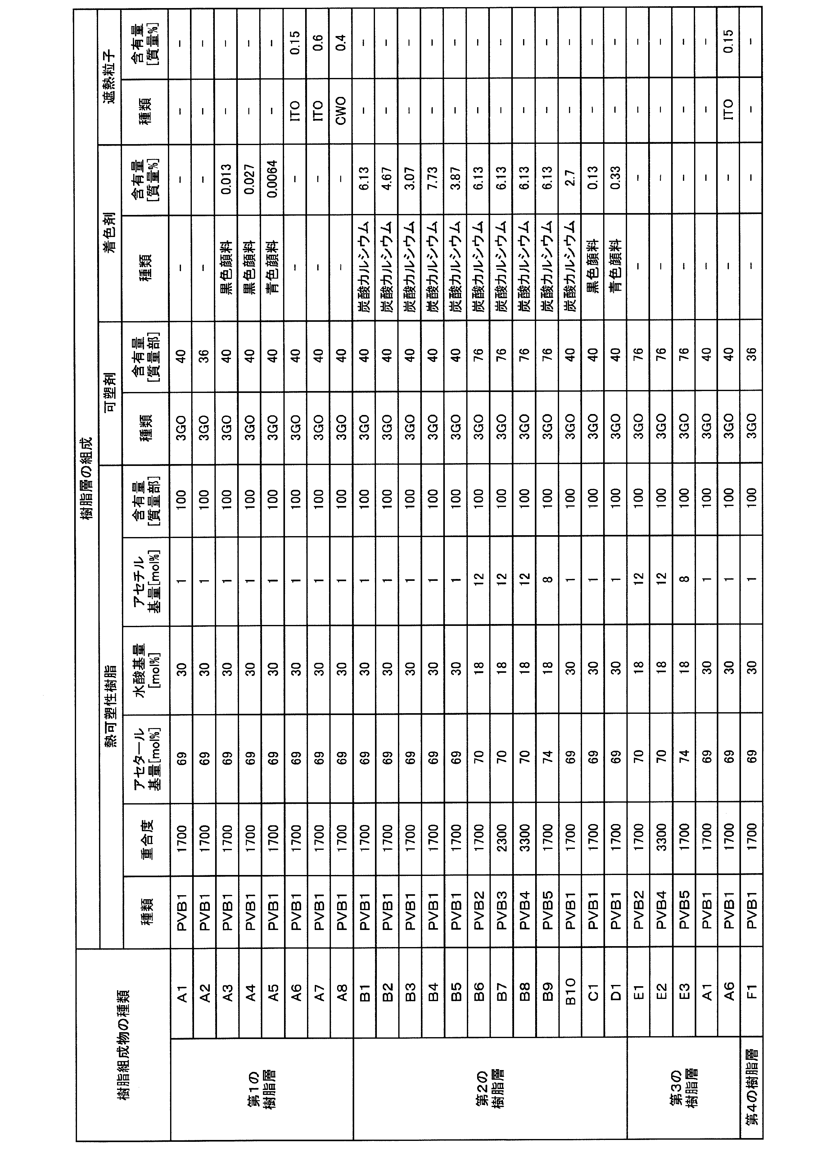


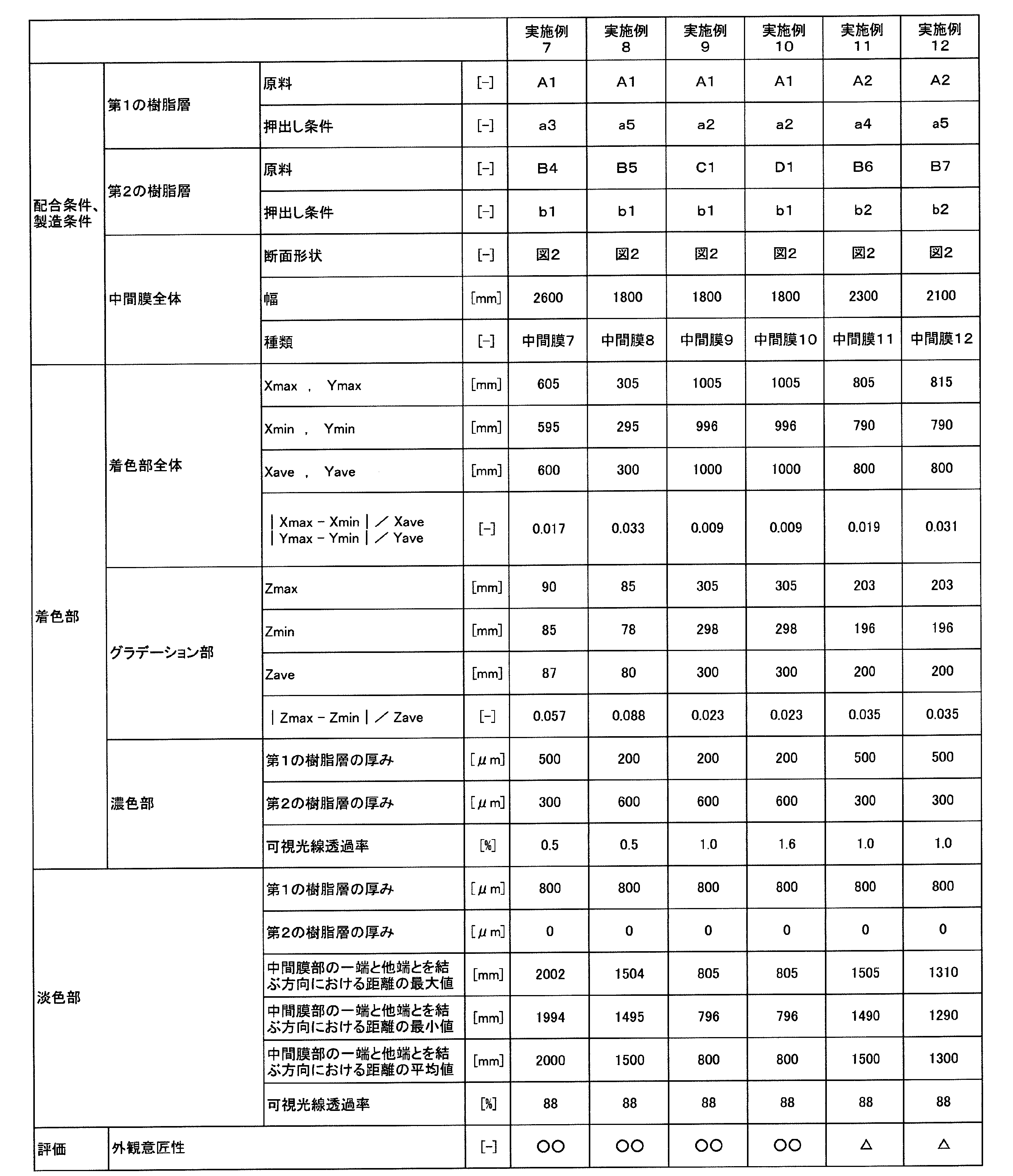
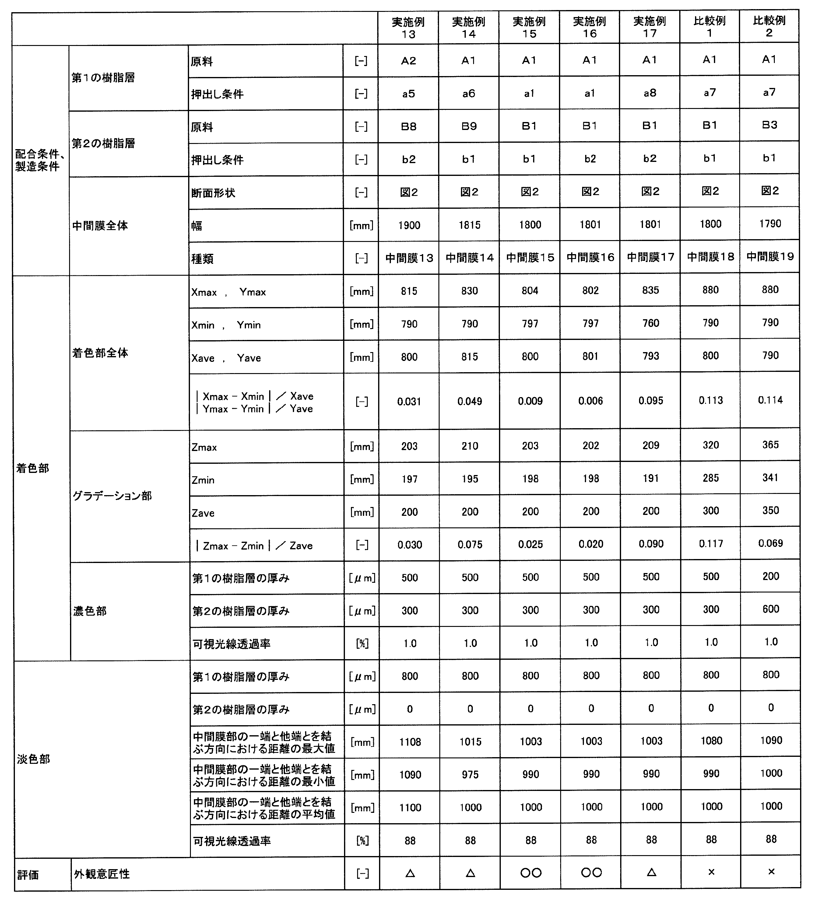
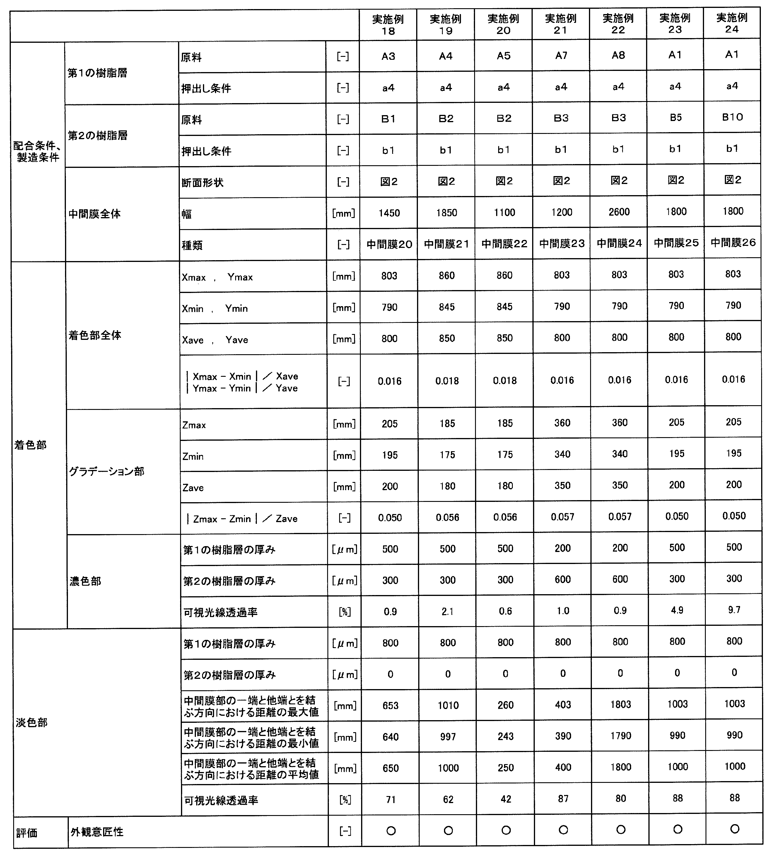

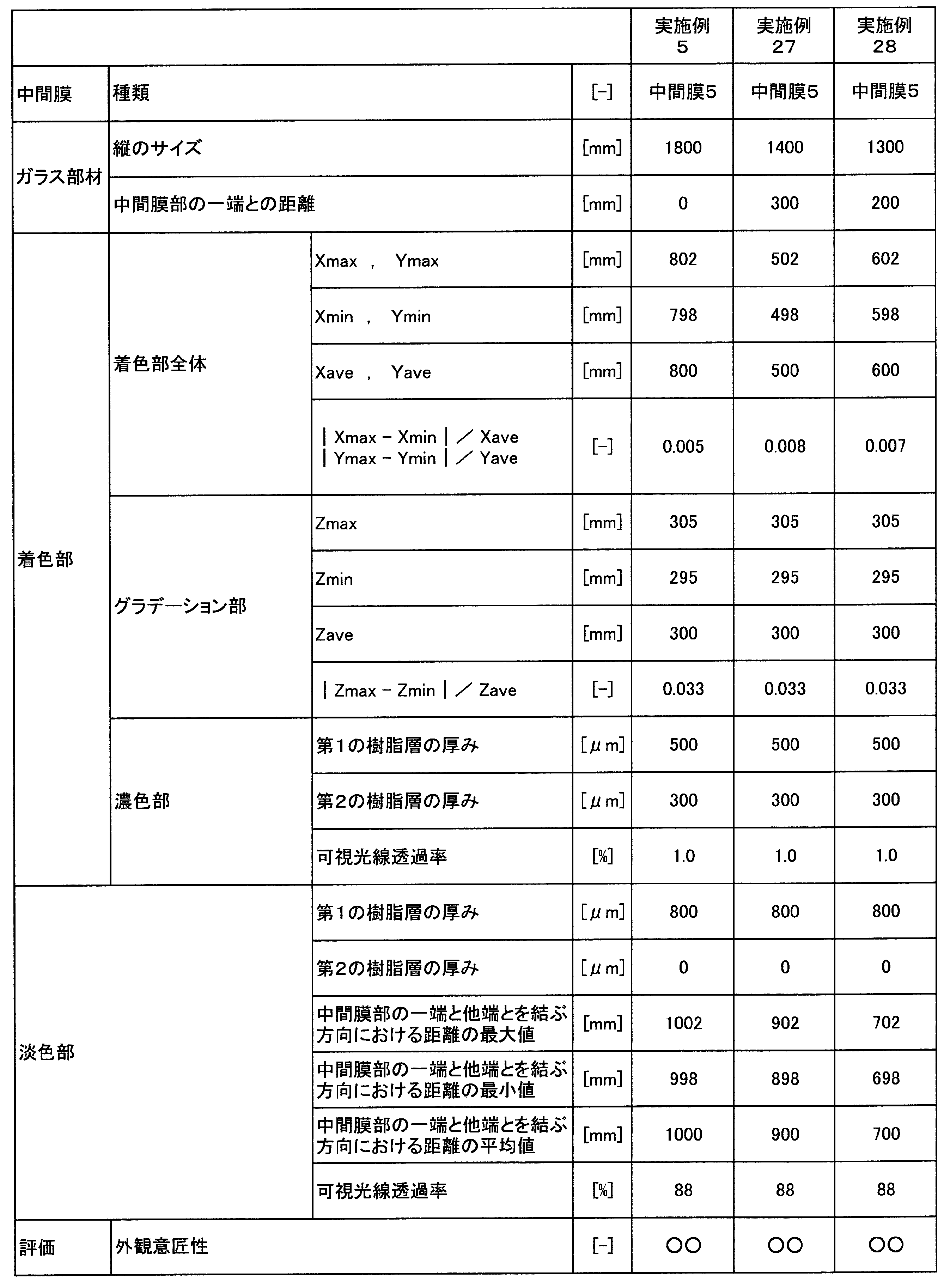
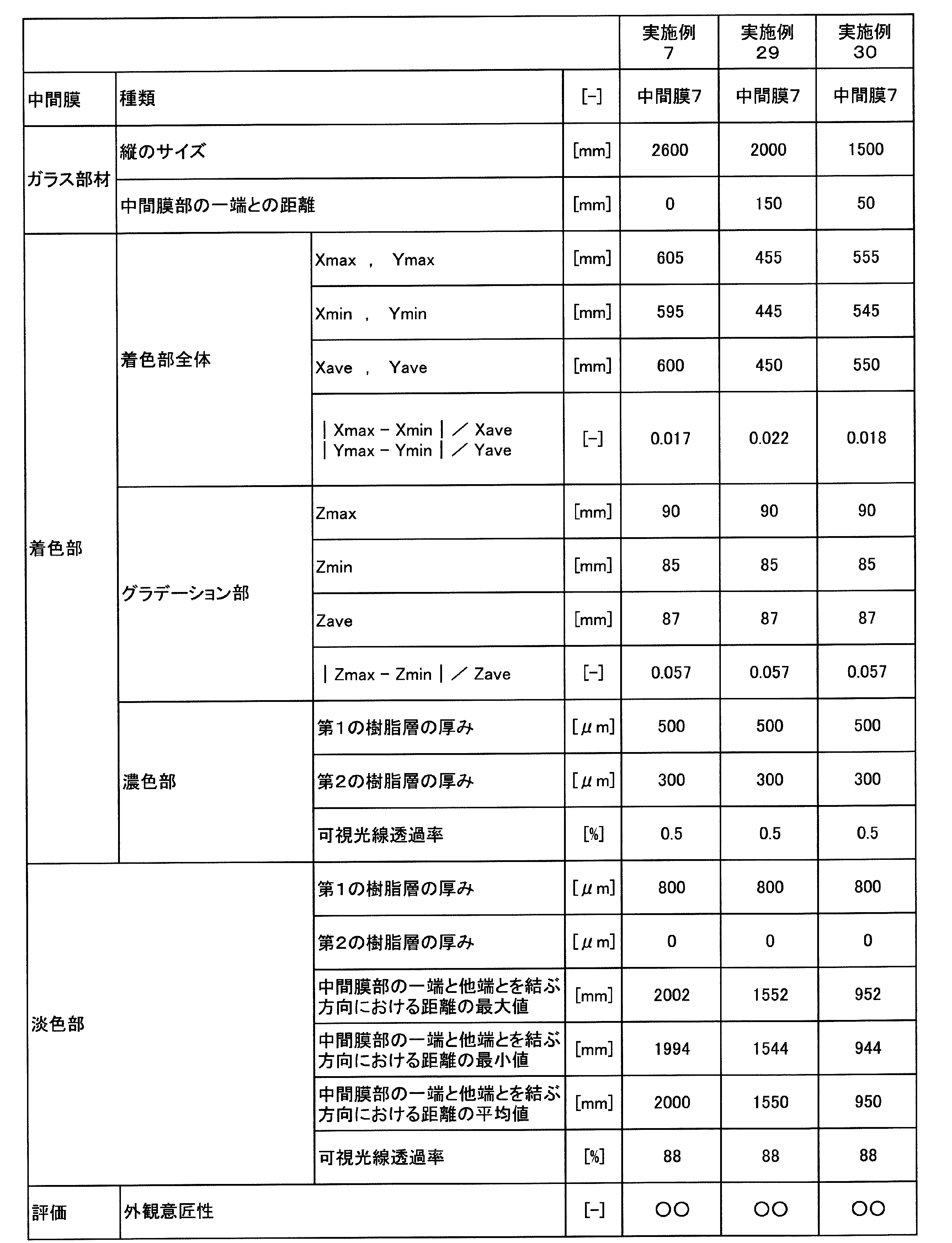

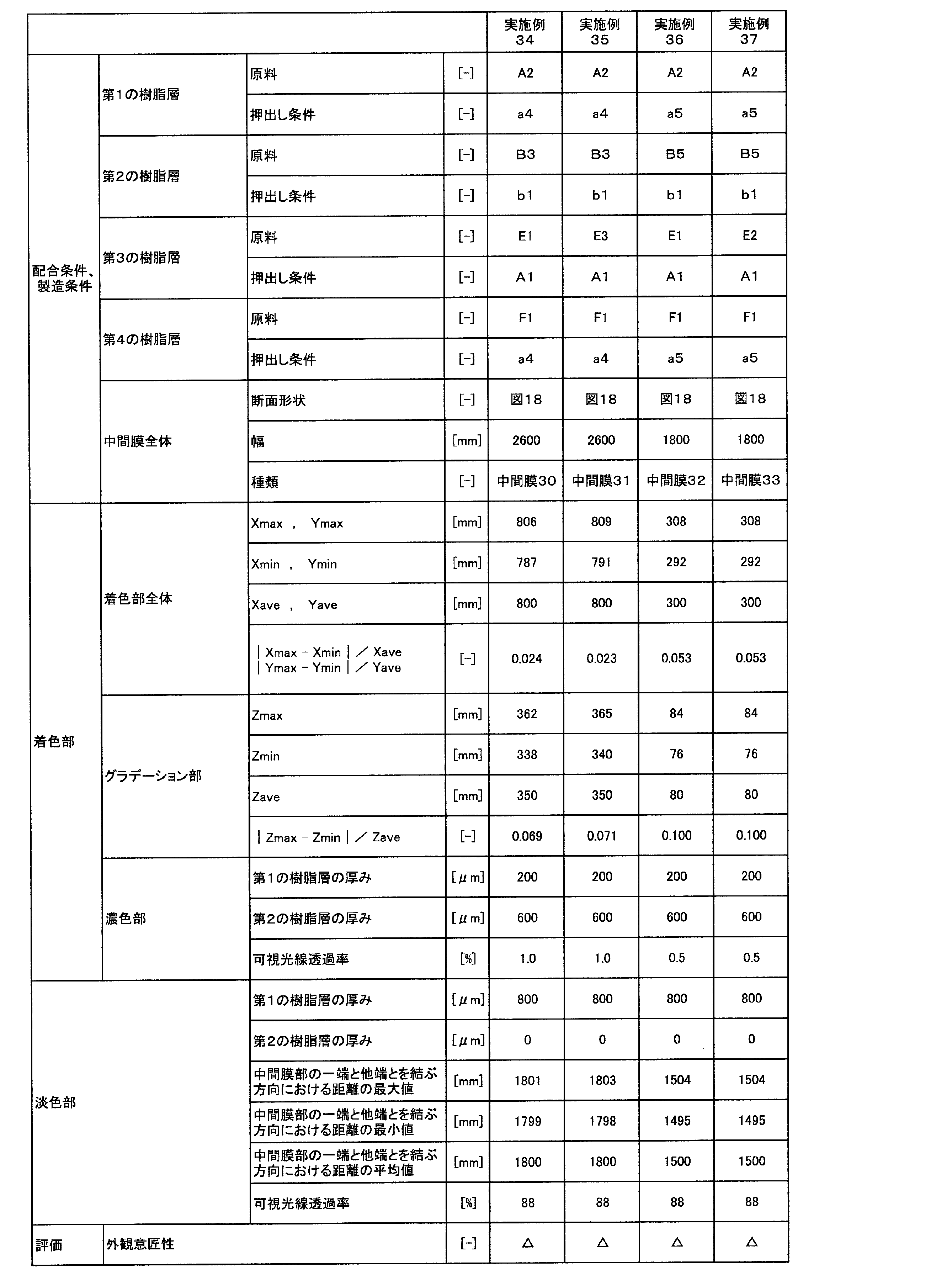
2,2A,2B,2C,2D,2E,2F,2G…第2の樹脂層
2X,2AX,2CX,2DX,2EX,2FX,2GX,4GX…グラデーション部
2BX…第1のグラデーション部
2Y,2AY,2CY,2DY,2EY,2FY,2GY,4GY…濃色部
2BZ…第2のグラデーション部
3E,3F,3G…第3の樹脂層
4E,4G…第4の樹脂層
5F…機能フィルム
11,11A,11B,11C,11D,11E,11F,11G…中間膜
11P,11AP,11BP,11CP,11DP,11EP,11FP,11GP…中間膜部
11a,11Aa,11Ba,11Ca,11Da,11Ea,11Fa,11Ga…一端
11b,11Ab,11Bb,11Cb,11Db,11Eb,11Fb,11Gb…他端
21…第1の合わせガラス部材
22…第2の合わせガラス部材
31,31A,31B,31C,31D,31E,31F,31G…合わせガラス
51,51A,51B…ロール体
61…巻き芯
71…合わせガラスセット
81,82…合わせガラス構造体
91,92…接続部材
Q…着色剤
Claims (12)
- 複数の合わせガラスのセットであり、
複数の前記合わせガラスのそれぞれが、第1の合わせガラス部材と、第2の合わせガラス部材と、前記第1の合わせガラス部材と前記第2の合わせガラス部材との間に配置された中間膜部とを備え、
前記中間膜部は、一端と、前記一端とは反対側に他端とを有し、
前記中間膜部は、着色部を有し、
前記着色部は、前記中間膜部の前記一端側から前記他端側に向けて可視光線透過率が高くなるグラデーション部を有し、前記グラデーション部は、前記中間膜部の前記他端側における前記着色部の先端を構成しており、
複数の前記合わせガラスのそれぞれにおいて前記中間膜部の前記一端から前記中間膜部の前記他端側における前記着色部の先端までの距離Xを測定し、距離Xの最大値をXmax、距離Xの最小値をXmin、距離Xの平均値をXaveとしたときに、下記式(1)を満たすか、又は、
複数の前記合わせガラスのそれぞれにおいて前記中間膜部の前記一端と前記他端とを結ぶ方向における前記着色部の距離Yを測定し、距離Yの最大値をYmax、距離Yの最小値をYmin、距離Yの平均値をYaveとしたときに、下記式(2)を満たす、合わせガラスセット。
(|Xmax-Xmin|)/Xave≦0.1 ・・・式(1)
(|Ymax-Ymin|)/Yave≦0.1 ・・・式(2) - 前記式(1)を満たす、請求項1に記載の合わせガラスセット。
- 前記Xminが0.6m以上である、請求項2に記載の合わせガラスセット。
- 前記中間膜部の前記一端側における前記着色部の先端が、前記中間膜部の前記一端に至っている、請求項1~3のいずれか1項に記載の合わせガラスセット。
- 前記式(2)を満たす、請求項1~4のいずれか1項に記載の合わせガラスセット。
- 前記Yminが0.6m以上である、請求項5に記載の合わせガラスセット。
- 複数の前記合わせガラスのそれぞれにおいて前記中間膜部の前記一端と前記他端とを結ぶ方向における前記グラデーション部の距離Zを測定し、距離Zの最大値をZmax、距離Zの最小値をZmin、距離Zの平均値をZaveとしたときに、下記式(3)を満たす、請求項1~6のいずれか1項に記載の合わせガラスセット。
(|Zmax-Zmin|)/Zave≦0.1 ・・・式(3) - 前記中間膜部は第1の樹脂層と第2の樹脂層とを備え、
前記第2の樹脂層の第1の表面側に第1の樹脂層が配置されており、
前記第2の樹脂層が着色剤を含み、
前記第2の樹脂層により前記着色部が形成されている、請求項1~7のいずれか1項に記載の合わせガラスセット。 - 前記着色剤が炭酸カルシウム粒子を含む、請求項8に記載の合わせガラスセット。
- 前記第2の樹脂層の前記第1の表面とは反対側の第2の表面に前記第1の樹脂層が配置されている、請求項8又は9に記載の合わせガラスセット。
- 前記着色部が、前記中間膜部の前記一端側から前記他端側に向けて可視光線透過率が均一である濃色部を有し、
前記中間膜部において、前記濃色部は、前記グラデーション部よりも中間膜部の前記一端側に位置する、請求項1~10のいずれか1項に記載の合わせガラスセット。 - 請求項1~11のいずれか1項に記載の合わせガラスセットと、
前記合わせガラスセットにおける複数の前記合わせガラスを接続している接続部材とを備える、合わせガラス構造体。
Priority Applications (5)
| Application Number | Priority Date | Filing Date | Title |
|---|---|---|---|
| EP19851218.8A EP3842396B1 (en) | 2018-08-20 | 2019-08-20 | Laminated glass set and laminated glass structure |
| CN201980048534.2A CN112469680A (zh) | 2018-08-20 | 2019-08-20 | 夹层玻璃套件以及夹层玻璃结构体 |
| BR112021001599-0A BR112021001599B1 (pt) | 2018-08-20 | 2019-08-20 | Conjunto de vidros laminados e estrutura de vidro laminado |
| JP2019550255A JP6875543B2 (ja) | 2018-08-20 | 2019-08-20 | 合わせガラスセット及び合わせガラス構造体 |
| US17/268,275 US11945191B2 (en) | 2018-08-20 | 2019-08-20 | Laminated glass set and laminated glass structure |
Applications Claiming Priority (2)
| Application Number | Priority Date | Filing Date | Title |
|---|---|---|---|
| JP2018154156 | 2018-08-20 | ||
| JP2018-154156 | 2018-08-20 |
Publications (1)
| Publication Number | Publication Date |
|---|---|
| WO2020040115A1 true WO2020040115A1 (ja) | 2020-02-27 |
Family
ID=69592639
Family Applications (1)
| Application Number | Title | Priority Date | Filing Date |
|---|---|---|---|
| PCT/JP2019/032372 Ceased WO2020040115A1 (ja) | 2018-08-20 | 2019-08-20 | 合わせガラスセット及び合わせガラス構造体 |
Country Status (6)
| Country | Link |
|---|---|
| US (1) | US11945191B2 (ja) |
| EP (1) | EP3842396B1 (ja) |
| JP (2) | JP6875543B2 (ja) |
| CN (1) | CN112469680A (ja) |
| TW (1) | TWI881948B (ja) |
| WO (1) | WO2020040115A1 (ja) |
Cited By (2)
| Publication number | Priority date | Publication date | Assignee | Title |
|---|---|---|---|---|
| WO2021201040A1 (ja) * | 2020-03-31 | 2021-10-07 | 積水化学工業株式会社 | 合わせガラス用中間膜、及び合わせガラス |
| US20230358937A1 (en) * | 2020-09-14 | 2023-11-09 | Saint-Gobain Glass France | Laminated glazing with reduced outside light reflection and head-up display with improved visibility |
Citations (5)
| Publication number | Priority date | Publication date | Assignee | Title |
|---|---|---|---|---|
| JP2006001807A (ja) * | 2004-06-18 | 2006-01-05 | Shinko Glass Industry Co Ltd | 多色で高意匠性な合わせガラス |
| WO2006082800A1 (ja) | 2005-02-03 | 2006-08-10 | Sekisui Chemical Co., Ltd. | 合わせガラス用中間膜および合わせガラス |
| WO2014077328A1 (ja) | 2012-11-14 | 2014-05-22 | 積水化学工業株式会社 | 合わせガラス用中間膜及び合わせガラス |
| WO2015072538A1 (ja) | 2013-11-14 | 2015-05-21 | 積水化学工業株式会社 | 合わせガラス用中間膜及び合わせガラス |
| WO2016163486A1 (ja) * | 2015-04-08 | 2016-10-13 | 積水化学工業株式会社 | 合わせガラス用中間膜及び合わせガラス |
Family Cites Families (11)
| Publication number | Priority date | Publication date | Assignee | Title |
|---|---|---|---|---|
| JPH0794142B2 (ja) * | 1990-07-03 | 1995-10-11 | 積水化学工業株式会社 | 熱可塑性樹脂シートの製造装置及びそれを用いた熱可塑性樹脂シートの製造方法 |
| DE19803362A1 (de) | 1998-01-29 | 1999-08-05 | Sartorius Gmbh | Geschäumte poröse Membranen aus thermoplastischen Polymeren sowie Verfahren und Vorrichtung zu ihrer Herstellung |
| US6960616B2 (en) | 1998-01-29 | 2005-11-01 | Sartorius Ag | Expanded porous thermoplastic polymer membranes |
| JP3756089B2 (ja) | 2001-08-30 | 2006-03-15 | 日立造船株式会社 | 押出成形設備 |
| EP1524247A1 (en) | 2003-10-15 | 2005-04-20 | Asahi Glass Company, Limited | Infrared shielding film-coated glass and process for its production |
| JP2007055822A (ja) | 2005-08-22 | 2007-03-08 | Sekisui Chem Co Ltd | 合わせガラス用中間膜および合わせガラス |
| CN102471153B (zh) * | 2009-08-12 | 2014-09-17 | 旭硝子株式会社 | 车辆用夹层玻璃 |
| JP5845114B2 (ja) | 2012-03-05 | 2016-01-20 | 株式会社神戸製鋼所 | 混練押出設備およびその運転制御方法 |
| US10024580B2 (en) * | 2014-01-22 | 2018-07-17 | Pegasus Solar Inc. | Corner connection bracket for solar energy panels |
| KR102444376B1 (ko) * | 2014-09-30 | 2022-09-16 | 세키스이가가쿠 고교가부시키가이샤 | 합판 유리용 중간막, 합판 유리 및 합판 유리용 중간막의 제조 방법 |
| CN106049730A (zh) * | 2016-08-03 | 2016-10-26 | 无锡金城幕墙装饰工程有限公司 | 一种可带角度拼接的异形单元幕墙系统 |
-
2019
- 2019-08-20 TW TW108129656A patent/TWI881948B/zh active
- 2019-08-20 JP JP2019550255A patent/JP6875543B2/ja active Active
- 2019-08-20 US US17/268,275 patent/US11945191B2/en active Active
- 2019-08-20 WO PCT/JP2019/032372 patent/WO2020040115A1/ja not_active Ceased
- 2019-08-20 EP EP19851218.8A patent/EP3842396B1/en active Active
- 2019-08-20 CN CN201980048534.2A patent/CN112469680A/zh active Pending
-
2021
- 2021-04-13 JP JP2021067868A patent/JP2021107322A/ja active Pending
Patent Citations (5)
| Publication number | Priority date | Publication date | Assignee | Title |
|---|---|---|---|---|
| JP2006001807A (ja) * | 2004-06-18 | 2006-01-05 | Shinko Glass Industry Co Ltd | 多色で高意匠性な合わせガラス |
| WO2006082800A1 (ja) | 2005-02-03 | 2006-08-10 | Sekisui Chemical Co., Ltd. | 合わせガラス用中間膜および合わせガラス |
| WO2014077328A1 (ja) | 2012-11-14 | 2014-05-22 | 積水化学工業株式会社 | 合わせガラス用中間膜及び合わせガラス |
| WO2015072538A1 (ja) | 2013-11-14 | 2015-05-21 | 積水化学工業株式会社 | 合わせガラス用中間膜及び合わせガラス |
| WO2016163486A1 (ja) * | 2015-04-08 | 2016-10-13 | 積水化学工業株式会社 | 合わせガラス用中間膜及び合わせガラス |
Non-Patent Citations (1)
| Title |
|---|
| See also references of EP3842396A4 |
Cited By (5)
| Publication number | Priority date | Publication date | Assignee | Title |
|---|---|---|---|---|
| WO2021201040A1 (ja) * | 2020-03-31 | 2021-10-07 | 積水化学工業株式会社 | 合わせガラス用中間膜、及び合わせガラス |
| JPWO2021201040A1 (ja) * | 2020-03-31 | 2021-10-07 | ||
| CN115003643A (zh) * | 2020-03-31 | 2022-09-02 | 积水化学工业株式会社 | 夹层玻璃用中间膜及夹层玻璃 |
| JP7698576B2 (ja) | 2020-03-31 | 2025-06-25 | 積水化学工業株式会社 | 合わせガラス用中間膜、及び合わせガラス |
| US20230358937A1 (en) * | 2020-09-14 | 2023-11-09 | Saint-Gobain Glass France | Laminated glazing with reduced outside light reflection and head-up display with improved visibility |
Also Published As
| Publication number | Publication date |
|---|---|
| BR112021001599A2 (pt) | 2021-04-20 |
| TWI881948B (zh) | 2025-05-01 |
| US20210323276A1 (en) | 2021-10-21 |
| EP3842396A4 (en) | 2022-04-27 |
| EP3842396B1 (en) | 2024-10-09 |
| JP6875543B2 (ja) | 2021-05-26 |
| EP3842396A1 (en) | 2021-06-30 |
| JPWO2020040115A1 (ja) | 2020-08-27 |
| US11945191B2 (en) | 2024-04-02 |
| CN112469680A (zh) | 2021-03-09 |
| TW202015911A (zh) | 2020-05-01 |
| JP2021107322A (ja) | 2021-07-29 |
Similar Documents
| Publication | Publication Date | Title |
|---|---|---|
| JP6875544B2 (ja) | 合わせガラス用中間膜、ロール体及び合わせガラスセットの製造方法 | |
| US11958270B2 (en) | Intermediate film for laminated glasses, laminated glass, and method for manufacturing head up display system | |
| US11298919B2 (en) | Interlayer for laminated glass, and laminated glass | |
| US20200406587A1 (en) | Interlayer for laminated glass, laminated glass, and method of manufacturing head-up display system | |
| EP3604251A1 (en) | Intermediate film for laminated glasses, and laminated glass | |
| JP6875543B2 (ja) | 合わせガラスセット及び合わせガラス構造体 | |
| JP2025146862A (ja) | 合わせガラス用中間膜及び合わせガラス | |
| WO2019189734A1 (ja) | 合わせガラス用中間膜、合わせガラス及び合わせガラスの取り付け方法 | |
| EP3730465A1 (en) | Laminated glass | |
| JP7824768B2 (ja) | 合わせガラス及び車両 | |
| JP2019108253A (ja) | 合わせガラス |
Legal Events
| Date | Code | Title | Description |
|---|---|---|---|
| ENP | Entry into the national phase |
Ref document number: 2019550255 Country of ref document: JP Kind code of ref document: A |
|
| 121 | Ep: the epo has been informed by wipo that ep was designated in this application |
Ref document number: 19851218 Country of ref document: EP Kind code of ref document: A1 |
|
| REG | Reference to national code |
Ref country code: BR Ref legal event code: B01A Ref document number: 112021001599 Country of ref document: BR |
|
| NENP | Non-entry into the national phase |
Ref country code: DE |
|
| ENP | Entry into the national phase |
Ref document number: 2019851218 Country of ref document: EP Effective date: 20210322 |
|
| ENP | Entry into the national phase |
Ref document number: 112021001599 Country of ref document: BR Kind code of ref document: A2 Effective date: 20210128 |