WO2020044652A1 - 正極活物質およびそれを備えた電池 - Google Patents
正極活物質およびそれを備えた電池 Download PDFInfo
- Publication number
- WO2020044652A1 WO2020044652A1 PCT/JP2019/016945 JP2019016945W WO2020044652A1 WO 2020044652 A1 WO2020044652 A1 WO 2020044652A1 JP 2019016945 W JP2019016945 W JP 2019016945W WO 2020044652 A1 WO2020044652 A1 WO 2020044652A1
- Authority
- WO
- WIPO (PCT)
- Prior art keywords
- positive electrode
- electrode active
- active material
- composite oxide
- lithium composite
- Prior art date
- Legal status (The legal status is an assumption and is not a legal conclusion. Google has not performed a legal analysis and makes no representation as to the accuracy of the status listed.)
- Ceased
Links
Images



Classifications
-
- H—ELECTRICITY
- H01—ELECTRIC ELEMENTS
- H01M—PROCESSES OR MEANS, e.g. BATTERIES, FOR THE DIRECT CONVERSION OF CHEMICAL ENERGY INTO ELECTRICAL ENERGY
- H01M4/00—Electrodes
- H01M4/02—Electrodes composed of, or comprising, active material
- H01M4/13—Electrodes for accumulators with non-aqueous electrolyte, e.g. for lithium-accumulators; Processes of manufacture thereof
- H01M4/139—Processes of manufacture
- H01M4/1391—Processes of manufacture of electrodes based on mixed oxides or hydroxides, or on mixtures of oxides or hydroxides, e.g. LiCoOx
-
- H—ELECTRICITY
- H01—ELECTRIC ELEMENTS
- H01M—PROCESSES OR MEANS, e.g. BATTERIES, FOR THE DIRECT CONVERSION OF CHEMICAL ENERGY INTO ELECTRICAL ENERGY
- H01M4/00—Electrodes
- H01M4/02—Electrodes composed of, or comprising, active material
- H01M4/36—Selection of substances as active materials, active masses, active liquids
- H01M4/48—Selection of substances as active materials, active masses, active liquids of inorganic oxides or hydroxides
- H01M4/52—Selection of substances as active materials, active masses, active liquids of inorganic oxides or hydroxides of nickel, cobalt or iron
- H01M4/525—Selection of substances as active materials, active masses, active liquids of inorganic oxides or hydroxides of nickel, cobalt or iron of mixed oxides or hydroxides containing iron, cobalt or nickel for inserting or intercalating light metals, e.g. LiNiO2, LiCoO2 or LiCoOxFy
-
- C—CHEMISTRY; METALLURGY
- C01—INORGANIC CHEMISTRY
- C01G—COMPOUNDS CONTAINING METALS NOT COVERED BY SUBCLASSES C01D OR C01F
- C01G53/00—Compounds of nickel
-
- H—ELECTRICITY
- H01—ELECTRIC ELEMENTS
- H01M—PROCESSES OR MEANS, e.g. BATTERIES, FOR THE DIRECT CONVERSION OF CHEMICAL ENERGY INTO ELECTRICAL ENERGY
- H01M10/00—Secondary cells; Manufacture thereof
- H01M10/05—Accumulators with non-aqueous electrolyte
- H01M10/052—Li-accumulators
- H01M10/0525—Rocking-chair batteries, i.e. batteries with lithium insertion or intercalation in both electrodes; Lithium-ion batteries
-
- H—ELECTRICITY
- H01—ELECTRIC ELEMENTS
- H01M—PROCESSES OR MEANS, e.g. BATTERIES, FOR THE DIRECT CONVERSION OF CHEMICAL ENERGY INTO ELECTRICAL ENERGY
- H01M10/00—Secondary cells; Manufacture thereof
- H01M10/05—Accumulators with non-aqueous electrolyte
- H01M10/056—Accumulators with non-aqueous electrolyte characterised by the materials used as electrolytes, e.g. mixed inorganic/organic electrolytes
- H01M10/0561—Accumulators with non-aqueous electrolyte characterised by the materials used as electrolytes, e.g. mixed inorganic/organic electrolytes the electrolyte being constituted of inorganic materials only
- H01M10/0562—Solid materials
-
- H—ELECTRICITY
- H01—ELECTRIC ELEMENTS
- H01M—PROCESSES OR MEANS, e.g. BATTERIES, FOR THE DIRECT CONVERSION OF CHEMICAL ENERGY INTO ELECTRICAL ENERGY
- H01M10/00—Secondary cells; Manufacture thereof
- H01M10/05—Accumulators with non-aqueous electrolyte
- H01M10/056—Accumulators with non-aqueous electrolyte characterised by the materials used as electrolytes, e.g. mixed inorganic/organic electrolytes
- H01M10/0564—Accumulators with non-aqueous electrolyte characterised by the materials used as electrolytes, e.g. mixed inorganic/organic electrolytes the electrolyte being constituted of organic materials only
- H01M10/0566—Liquid materials
-
- H—ELECTRICITY
- H01—ELECTRIC ELEMENTS
- H01M—PROCESSES OR MEANS, e.g. BATTERIES, FOR THE DIRECT CONVERSION OF CHEMICAL ENERGY INTO ELECTRICAL ENERGY
- H01M4/00—Electrodes
- H01M4/02—Electrodes composed of, or comprising, active material
- H01M4/36—Selection of substances as active materials, active masses, active liquids
- H01M4/362—Composites
- H01M4/366—Composites as layered products
-
- H—ELECTRICITY
- H01—ELECTRIC ELEMENTS
- H01M—PROCESSES OR MEANS, e.g. BATTERIES, FOR THE DIRECT CONVERSION OF CHEMICAL ENERGY INTO ELECTRICAL ENERGY
- H01M4/00—Electrodes
- H01M4/02—Electrodes composed of, or comprising, active material
- H01M4/36—Selection of substances as active materials, active masses, active liquids
- H01M4/48—Selection of substances as active materials, active masses, active liquids of inorganic oxides or hydroxides
- H01M4/50—Selection of substances as active materials, active masses, active liquids of inorganic oxides or hydroxides of manganese
- H01M4/505—Selection of substances as active materials, active masses, active liquids of inorganic oxides or hydroxides of manganese of mixed oxides or hydroxides containing manganese for inserting or intercalating light metals, e.g. LiMn2O4 or LiMn2OxFy
-
- C—CHEMISTRY; METALLURGY
- C01—INORGANIC CHEMISTRY
- C01P—INDEXING SCHEME RELATING TO STRUCTURAL AND PHYSICAL ASPECTS OF SOLID INORGANIC COMPOUNDS
- C01P2002/00—Crystal-structural characteristics
- C01P2002/70—Crystal-structural characteristics defined by measured X-ray, neutron or electron diffraction data
- C01P2002/72—Crystal-structural characteristics defined by measured X-ray, neutron or electron diffraction data by d-values or two theta-values, e.g. as X-ray diagram
-
- C—CHEMISTRY; METALLURGY
- C01—INORGANIC CHEMISTRY
- C01P—INDEXING SCHEME RELATING TO STRUCTURAL AND PHYSICAL ASPECTS OF SOLID INORGANIC COMPOUNDS
- C01P2002/00—Crystal-structural characteristics
- C01P2002/70—Crystal-structural characteristics defined by measured X-ray, neutron or electron diffraction data
- C01P2002/74—Crystal-structural characteristics defined by measured X-ray, neutron or electron diffraction data by peak-intensities or a ratio thereof only
-
- C—CHEMISTRY; METALLURGY
- C01—INORGANIC CHEMISTRY
- C01P—INDEXING SCHEME RELATING TO STRUCTURAL AND PHYSICAL ASPECTS OF SOLID INORGANIC COMPOUNDS
- C01P2002/00—Crystal-structural characteristics
- C01P2002/70—Crystal-structural characteristics defined by measured X-ray, neutron or electron diffraction data
- C01P2002/76—Crystal-structural characteristics defined by measured X-ray, neutron or electron diffraction data by a space-group or by other symmetry indications
-
- C—CHEMISTRY; METALLURGY
- C01—INORGANIC CHEMISTRY
- C01P—INDEXING SCHEME RELATING TO STRUCTURAL AND PHYSICAL ASPECTS OF SOLID INORGANIC COMPOUNDS
- C01P2004/00—Particle morphology
- C01P2004/01—Particle morphology depicted by an image
- C01P2004/04—Particle morphology depicted by an image obtained by TEM, STEM, STM or AFM
-
- C—CHEMISTRY; METALLURGY
- C01—INORGANIC CHEMISTRY
- C01P—INDEXING SCHEME RELATING TO STRUCTURAL AND PHYSICAL ASPECTS OF SOLID INORGANIC COMPOUNDS
- C01P2004/00—Particle morphology
- C01P2004/80—Particles consisting of a mixture of two or more inorganic phases
- C01P2004/82—Particles consisting of a mixture of two or more inorganic phases two phases having the same anion, e.g. both oxidic phases
- C01P2004/84—Particles consisting of a mixture of two or more inorganic phases two phases having the same anion, e.g. both oxidic phases one phase coated with the other
-
- H—ELECTRICITY
- H01—ELECTRIC ELEMENTS
- H01M—PROCESSES OR MEANS, e.g. BATTERIES, FOR THE DIRECT CONVERSION OF CHEMICAL ENERGY INTO ELECTRICAL ENERGY
- H01M10/00—Secondary cells; Manufacture thereof
- H01M10/05—Accumulators with non-aqueous electrolyte
- H01M10/052—Li-accumulators
-
- H—ELECTRICITY
- H01—ELECTRIC ELEMENTS
- H01M—PROCESSES OR MEANS, e.g. BATTERIES, FOR THE DIRECT CONVERSION OF CHEMICAL ENERGY INTO ELECTRICAL ENERGY
- H01M4/00—Electrodes
- H01M4/02—Electrodes composed of, or comprising, active material
- H01M2004/021—Physical characteristics, e.g. porosity, surface area
-
- H—ELECTRICITY
- H01—ELECTRIC ELEMENTS
- H01M—PROCESSES OR MEANS, e.g. BATTERIES, FOR THE DIRECT CONVERSION OF CHEMICAL ENERGY INTO ELECTRICAL ENERGY
- H01M4/00—Electrodes
- H01M4/02—Electrodes composed of, or comprising, active material
- H01M2004/026—Electrodes composed of, or comprising, active material characterised by the polarity
- H01M2004/028—Positive electrodes
-
- H—ELECTRICITY
- H01—ELECTRIC ELEMENTS
- H01M—PROCESSES OR MEANS, e.g. BATTERIES, FOR THE DIRECT CONVERSION OF CHEMICAL ENERGY INTO ELECTRICAL ENERGY
- H01M2300/00—Electrolytes
- H01M2300/0017—Non-aqueous electrolytes
- H01M2300/0025—Organic electrolyte
-
- H—ELECTRICITY
- H01—ELECTRIC ELEMENTS
- H01M—PROCESSES OR MEANS, e.g. BATTERIES, FOR THE DIRECT CONVERSION OF CHEMICAL ENERGY INTO ELECTRICAL ENERGY
- H01M2300/00—Electrolytes
- H01M2300/0017—Non-aqueous electrolytes
- H01M2300/0065—Solid electrolytes
- H01M2300/0068—Solid electrolytes inorganic
-
- Y—GENERAL TAGGING OF NEW TECHNOLOGICAL DEVELOPMENTS; GENERAL TAGGING OF CROSS-SECTIONAL TECHNOLOGIES SPANNING OVER SEVERAL SECTIONS OF THE IPC; TECHNICAL SUBJECTS COVERED BY FORMER USPC CROSS-REFERENCE ART COLLECTIONS [XRACs] AND DIGESTS
- Y02—TECHNOLOGIES OR APPLICATIONS FOR MITIGATION OR ADAPTATION AGAINST CLIMATE CHANGE
- Y02E—REDUCTION OF GREENHOUSE GAS [GHG] EMISSIONS, RELATED TO ENERGY GENERATION, TRANSMISSION OR DISTRIBUTION
- Y02E60/00—Enabling technologies; Technologies with a potential or indirect contribution to GHG emissions mitigation
- Y02E60/10—Energy storage using batteries
Definitions
- the present disclosure relates to a positive electrode active material and a battery including the same.
- Patent Literature 1 discloses a lithium-containing composite oxide containing Li, Ni, Co, and Mn as essential components.
- the lithium composite oxide disclosed in Patent Document 1 has a space group of space group R-3m, and has a c-axis lattice constant of 1.4208 to 1.4228 nanometers.
- the lithium composite oxide has a crystal structure in which the a-axis lattice constant and the c-axis lattice constant satisfy the relationship of (3a + 5.615) ⁇ c ⁇ (3a + 5.655).
- the integrated intensity ratio (I 003 / I 104 ) of the peak (003) to the peak (104) in the X-ray diffraction pattern is 1.21 to 1.39.
- An object of the present invention is to provide a positive electrode active material used for a battery having a small voltage drop.
- the first lithium composite oxide contains at least one selected from the group consisting of F, Cl, N, and S;
- the first lithium composite oxide has a crystal structure belonging to a layered structure,
- the second lithium composite oxide has a crystal structure belonging to the space group Fd-3m, and satisfies the following formula (I): 0.05 ⁇ integrated intensity ratio I (18 ° -20 °) / I (43 ° -46 °) ⁇ 0.90 (I) here,
- the integrated intensity ratio I (18 ° -20 °) / I (43 ° -46 °) is equal to the ratio of the integrated intensity I (18 ° -20 °) to the integrated intensity I (43 ° -46 °) ,
- the integrated intensity I (18 ° -20 °) is the integrated intensity of the first peak, which is the maximum peak in the diffraction angle 2 ⁇ range of 18
- the integrated intensity I (43 ° -46 °) is the maximum peak of the second peak in the range of the diffraction angle 2 ⁇ of 43 ° or more and 46 ° or less in the X-ray diffraction pattern of the positive electrode active material. This is the integral intensity.
- the present invention provides a positive electrode active material used for a battery having a small voltage drop.
- the present invention also includes a battery including a positive electrode including the positive electrode active material, a negative electrode, and an electrolyte.
- the battery has a small voltage drop.
- FIG. 1 shows a cross-sectional view of a battery 10 according to the second embodiment.
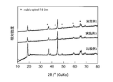
- FIG. 2 is a graph showing powder X-ray diffraction patterns of the positive electrode active materials of Example 1, Example 3, and Comparative Example 1.
- FIG. 3 is an image of a cross section of the positive electrode active material of Example 1 obtained by using a transmission electron microscope.
- FIG. 4 is a graph showing a change in an average operating voltage during repeated charging and discharging of the batteries of Example 1 and Comparative Example 1.
- the positive electrode active material in Embodiment 1 is A first lithium composite oxide, and a second lithium composite oxide covering at least a part of the surface of the first lithium composite oxide; here,
- the first lithium composite oxide contains at least one selected from the group consisting of F, Cl, N, and S;
- the first lithium composite oxide has a crystal structure belonging to a layered structure,
- the second lithium composite oxide has a crystal structure belonging to the space group Fd-3m, and satisfies the following formula (I): 0.05 ⁇ integrated intensity ratio I (18 ° -20 °) / I (43 ° -46 °) ⁇ 0.90 (I) here,
- the integrated intensity ratio I (18 ° -20 °) / I (43 ° -46 °) is equal to the ratio of the integrated intensity I (18 ° -20 °) to the integrated intensity I (43 ° -46 °) ,
- the integrated intensity I (18 ° -20 °) is the integrated intensity of the first peak, which is the maximum peak
- the integrated intensity I (43 ° -46 °) is the maximum peak of the second peak in the range of the diffraction angle 2 ⁇ between 43 ° and 46 ° in the X-ray diffraction pattern of the positive electrode active material. This is the integral intensity.
- the positive electrode active material is used to provide a battery having a small voltage drop.
- the “battery having a small voltage drop amount” means a battery having a high average operating voltage maintenance ratio even after repeated charge / discharge cycles. Furthermore, the battery has a high capacity.
- the positive electrode active material according to the first embodiment can be specified from a different viewpoint, for example, as follows.
- the positive electrode active material according to the first embodiment contains a lithium composite oxide containing at least one selected from the group consisting of F, Cl, N, and S and having a crystal structure belonging to a layered structure. Wherein at least a part of the surface of the lithium composite oxide is coated with a phase having a crystal structure belonging to a space group Fd-3m, and the positive electrode active material has a thickness of 0.05 to 0.90.
- a positive electrode active material having an integrated intensity ratio I (18 ° -20 °) / I (43 ° -46 °) .
- the lithium ion battery including the positive electrode active material in Embodiment 1 has an oxidation-reduction potential of about 3.4 V (Li / Li + reference).
- the first lithium composite oxide contains at least one element selected from the group consisting of F, Cl, N, and S. Since the at least one element is an electrochemically inactive anion, the crystal structure is stabilized by substituting a part of oxygen contained in the first lithium composite oxide with the at least one element. It is thought to be. As a result, it is considered that the discharge capacity or operating voltage of the battery is improved, and the energy density is increased.
- the first lithium composite oxide has a crystal structure belonging to a layered structure.
- the positive electrode active material of the first embodiment has an integrated intensity ratio I (18 ° -20 °) / I (43 ° -46 °) of 0.05 or more and 0.90 or less.
- the integrated intensity ratio I (18 ° -20 °) / I (43 ° -46 °) is a parameter that can be used as an indicator of cation mixing in the first lithium composite oxide having a crystal structure belonging to a layered structure.
- “Cation mixing” in the present disclosure means a state in which a lithium ion and a cation of a transition metal are substituted with each other in the crystal structure of the first lithium composite oxide.
- the integrated intensity ratio I (18 ° -20 °) / I (43 ° -46 °) increases.
- the integrated intensity ratio I (18 ° -20 °) / I (43 ° -46 °) decreases.
- the first lithium composite oxide has a Li layer and a transition metal layer.
- Lithium occupancy in the transition metal layer contained in the first lithium composite oxide when the positive electrode active material has an integrated intensity ratio I (18 ° -20 °) / I (43 ° -46 °) of less than 0.05 Becomes excessively high, and the crystal structure becomes unstable thermodynamically. As a result, the crystal structure collapses with the elimination of Li during charging, and the capacity becomes insufficient.
- the positive electrode active material has an integrated intensity ratio I (18 ° -20 °) / I (43 ° -46 °) greater than 0.90, the cation mixing is suppressed, and the first lithium composite oxide is reduced. Occupation ratio of Li in the transition metal layer included in the metal alloy becomes low. As a result, the three-dimensional diffusion path of Li decreases. For this reason, the diffusivity of Li decreases and the capacity becomes insufficient.
- the positive electrode active material of the first embodiment has an integrated intensity ratio I (18 ° -20 °) / I (43 ° -46 °) of 0.05 or more and 0.90 or less, the first lithium composite In the oxide, it is considered that cation mixing has sufficiently occurred between the lithium ion and the cation atom of the transition metal. As a result, in the first lithium composite oxide, the three-dimensional diffusion path of lithium is considered to be increased, so that more Li can be inserted and desorbed.
- the positive electrode active material of Embodiment 1 has an integrated intensity ratio I (18 ° -20 °) / I (43 ° -46 °) of 0.05 or more and 0.90 or less, the first lithium composite oxide Not only the diffusibility of Li inside the Li layer but also the diffusivity of Li inside the transition metal layer is improved. Further, the diffusibility of Li between the Li layer and the transition metal layer is also improved. That is, Li can efficiently diffuse in the entire cation site. For this reason, the lithium composite oxide is more suitable for increasing the capacity of the battery than a conventional ordered lithium composite oxide (that is, a lithium composite oxide having a small amount of cation mixing).
- the lithium composite oxide contained in the positive electrode active material disclosed in Patent Document 1 has a crystal structure belonging to the space group R-3m, which is a layered structure.
- cation mixing does not sufficiently occur between the lithium ion and the cation of the transition metal.
- the positive electrode active material in the first embodiment is a positive electrode active material including the first lithium composite oxide.
- the first lithium composite oxide contains at least one element selected from the group consisting of F, Cl, N, and S.
- the first lithium composite oxide has a crystal structure belonging to a layered structure.
- the integral intensity ratio I (18 ° -20 °) / I (43 ° -46 °) which is a parameter that can be used as an index of cation mixing in the first lithium composite oxide, It is 0.05 or more and 0.90 or less.
- the integrated intensity ratio I (18 ° -20 °) / I (43 ° -46 °) may be 0.11 or more and 0.85 or less.
- the integrated intensity ratio I (18 ° -20 °) / I (43 ° -46 °) may be 0.44 or more and 0.85 or less.
- the integrated intensity ratio I (18 ° -20 °) / I (43 ° -46 °) may be 0.55 or more and 0.59 or less.
- the integrated intensity of the X-ray diffraction peak can be calculated using, for example, software attached to the X-ray diffraction apparatus (for example, PDXL attached to a powder X-ray diffraction apparatus manufactured by Rigaku Corporation).
- the integrated intensity of the X-ray diffraction peak can be obtained, for example, by calculating the area from the height and the half width of each diffraction peak.
- the maximum peak having a diffraction angle 2 ⁇ in the range of 18 ° or more and 20 ° or less has a (001) plane. Reflects.
- the maximum peak in the range where the diffraction angle 2 ⁇ is 43 ° or more and 46 ° or less reflects the (114) plane.
- the maximum peak having a diffraction angle 2 ⁇ in the range of 18 ° or more and 20 ° or less has a (003) plane. Reflects.
- the maximum peak in the range where the diffraction angle 2 ⁇ is 43 ° or more and 46 ° or less reflects the (104) plane.
- the maximum peak having a diffraction angle 2 ⁇ in the range of 18 ° to 20 ° is The (111) plane is reflected.
- the maximum peak in the range where the diffraction angle 2 ⁇ is 43 ° or more and 46 ° or less reflects the (400) plane.
- the crystal structure belonging to the layered structure is a hexagonal crystal structure or a monoclinic crystal structure. You may.
- the crystal structure belonging to the layered structure is selected from the group consisting of the space group C2 / m and the space group R-3m. May belong to at least one of them.
- the crystal structure belonging to the layered structure may belong to the space group C2 / m.
- the integrated intensity ratio I (18 ° -20 °) / I (43 ° -46 °) is a parameter serving as an index of cation mixing in the first lithium composite oxide.
- the positive electrode active material of the first embodiment has an integrated intensity ratio I (18 ° -20 °) / I (43 ° -46 °) of 0.05 or more and 0.90 or less.
- I (18 ° -20 °) / I (43 ° -46 °) of 0.05 or more and 0.90 or less.
- the first lithium composite oxide has a crystal structure belonging to the space group C2 / m, it functions as a pillar even when a large amount of Li is extracted.
- the transition metal-anion octahedron forms a three-dimensional network and can stably maintain the crystal structure. As a result, a battery having excellent capacity and cycle characteristics can be obtained.
- the crystal structure belonging to the space group C2 / m is easier to maintain the layered structure when Li is extracted more than the layered structure belonging to the space group R-3m. Therefore, it is considered that the crystal structure belonging to the space group C2 / m is less likely to collapse than the layered structure belonging to the space group R-3m.
- the first lithium composite oxide may include not only the crystal structure belonging to the above-mentioned layered structure but also another crystal structure (for example, a crystal structure belonging to the space group Fm-3m).
- the first lithium composite oxide may contain F.
- transition metals contained in the transition metal layer are Mn, Co, Ni, Fe, Cu, V, Nb, Mo, Ti, Cr, Zr, Zn, It may be at least one element selected from the group consisting of Na, K, Ca, Mg, Pt, Au, Ag, Ru, W, B, Si, P, and Al.
- the first lithium composite oxide contains at least one 3d transition metal element selected from the group consisting of Mn, Co, Ni, Fe, Cu, V, Ti, Cr, and Zn. May be.
- the first lithium composite oxide may contain Mn.
- the first lithium composite oxide may include not only Mn but also Co and Ni.
- Embodiment 1 an example of the chemical composition of the first lithium composite oxide will be described.
- the first lithium composite oxide may be a compound represented by the following composition formula (1).
- Li x Me y O ⁇ Q ⁇ formula (1) Me is Mn, Co, Ni, Fe, Cu, V, Nb, Mo, Ti, Cr, Zr, Zn, Na, K, Ca, Mg, Pt, Au, Ag, Ru, W, B, Si, P , And at least one element selected from the group consisting of Al;
- Q is at least one element selected from the group consisting of F, Cl, N, and S;
- the following four mathematical expressions are satisfied. 1.05 ⁇ x ⁇ 1.4, 0.6 ⁇ y ⁇ 0.95, 1.33 ⁇ ⁇ ⁇ 2 and 0 ⁇ ⁇ 0.67.
- the above first lithium composite oxide further improves the capacity of the battery.
- Me may include at least one selected from the group consisting of Mn, Co, Ni, Fe, Cu, V, Ti, Cr, and Zn. That is, Me may include at least one 3d transition metal element.
- the molar ratio of Li to Me is represented by a mathematical formula (x / y).
- the molar ratio (x / y) may be 1.3 or more and 1.9 or less.
- the ratio of the number of Li atoms in the lithium composite oxide is higher than the ratio of the number of Li atoms in the conventional cathode active material represented by the composition formula LiMnO 2. . For this reason, it becomes possible to insert and remove more Li.
- the molar ratio (x / y) is 1.3 or more, the amount of Li that can be used is large, so that a Li diffusion path is appropriately formed. Therefore, when the molar ratio (x / y) is 1.3 or more, the capacity of the battery is further improved.
- the molar ratio (x / y) may be 1.3 or more and 1.7 or less.
- the molar ratio of O to Q is represented by the equation ( ⁇ / ⁇ ).
- the molar ratio ( ⁇ / ⁇ ) may be 9 or more and 39 or less.
- the molar ratio ( ⁇ / ⁇ ) may be 9 or more and 19 or less.
- the lithium composite oxide in Embodiment 1 may have a composition represented by the composition formula Li x Me y O ⁇ Q ⁇ . Therefore, the lithium composite oxide according to the first embodiment includes a cation portion and an anion portion.
- the cation moiety is composed of Li and Me.
- the anion moiety is composed of O and Q.
- the molar ratio of the cation moiety composed of Li and Me to the anion moiety composed of O and Q is represented by the formula ((x + y) / ( ⁇ + ⁇ )).
- the molar ratio ((x + y) / ( ⁇ + ⁇ )) may be 0.75 or more and 1.2 or less.
- the molar ratio ((x + y) / ( ⁇ + ⁇ )) is 0.75 or more, generation of a large amount of impurities during synthesis of the lithium composite oxide can be prevented, and the capacity of the battery can be further improved.
- the molar ratio ((x + y) / ( ⁇ + ⁇ )) may be 0.75 or more and 1.0 or less.
- Q may include F. That is, Q may be F.
- Or Q may include not only F but also at least one element selected from the group consisting of Cl, N, and S.
- Me is selected from the group consisting of Mn, Co, Ni, Fe, Cu, V, Nb, Ti, Cr, Na, Mg, Ru, W, B, Si, P, and Al. It may contain at least one selected element.
- Me may include Mn. That is, Me may be Mn.
- Me is not only Mn but also Co, Ni, Fe, Cu, V, Nb, Mo, Ti, Cr, Zr, Zn, Na, K, Ca, Mg, Pt, Au, Ag, Ru, W, It may also include at least one element selected from the group consisting of B, Si, P, and Al.
- the mixed orbital of Mn and oxygen is easily formed, so that the desorption of oxygen during charging is suppressed. As a result, the crystal structure is stabilized, and the capacity of the battery is further improved.
- the molar ratio of Mn to Me may be 60% or more. That is, the molar ratio of Mn (that is, the molar ratio of Mn / Me) to the whole Me including Mn may be 0.6 or more and 1.0 or less.
- the mixed orbital of Mn and oxygen sufficiently contains Mn that is easily formed, so that oxygen desorption during charging is further suppressed. For this reason, the crystal structure is stabilized, and a higher capacity battery can be realized.
- Me may include not only Mn but also Co and Ni.
- the lithium composite oxide containing not only Mn but also Co and Ni has a more stable crystal structure. Therefore, the lithium composite oxide containing not only Mn but also Co and Ni further improves the capacity of the battery.
- Me may include at least one element selected from the group consisting of B, Si, P, and Al such that the molar ratio of the at least one element to Me is 20% or less.
- part of Li may be replaced by an alkali metal such as Na or K.
- the positive electrode active material of the first embodiment includes the second lithium composite oxide covering at least a part of the surface of the first lithium composite oxide.
- a general positive electrode active material is used at a high potential, decomposition of the electrolyte (for example, a side reaction) is promoted, and there is a concern that the transition metal is eluted from the surface of the positive electrode active material.
- the anion species contained in the positive electrode active material is eliminated as a gas. As a result, the crystal structure of the positive electrode active material may change, and the operating voltage may decrease.
- the second lithium composite oxide has a crystal structure belonging to the space group Fd-3m.
- the X-ray diffraction pattern of the positive electrode active material of the first embodiment shows a diffraction angle 2 ⁇ of 63 ° or more and 66 ° or less as an index of the presence of the second lithium composite oxide having a crystal structure belonging to the space group Fd-3m.
- the range may have two or more peaks.
- the X-ray diffraction pattern has the two or more peaks, the effect of suppressing the crystal structure transition of the positive electrode active material by the second lithium composite oxide is increased. As a result, the average operating voltage drop of the battery can be further reduced.
- the following equation (II) may be satisfied. 1.18 ⁇ Integrated intensity ratio I (63 ° ⁇ 65 °) / I (65 ° ⁇ 66 °) ⁇ 2.0 (II) here,
- the integrated intensity ratio I (63 ° -65 °) / I (65 ° -66 °) is equal to the ratio of the integrated intensity I (63 ° -65 °) to the integrated intensity I (65 ° -66 °) ,
- the integrated intensity I (65 ° -66 °) is the integrated intensity of the third peak, which is the maximum peak in the range of the diffraction angle 2 ⁇ from 65 ° to 66 ° in the X-ray diffraction pattern of the positive electrode active material.
- the integrated intensity I (63 ° -65 °) is the maximum peak of the fourth peak in the X-ray diffraction pattern of the positive electrode active material in the range of the diffraction angle 2 ⁇ of 63 ° or more and 65 ° or less. This is the integral intensity.
- the integrated intensity ratio I (63 ° -65 °) / I (65 ° -66 °) is a parameter that can be used as an index of the existence ratio of the crystal structure belonging to the space group Fd-3m. It is considered that the integrated intensity ratio I (63 ° -65 °) / I (65 ° -66 °) increases as the proportion of the crystal structure belonging to the space group Fd-3m increases.
- the integrated intensity ratio I (63 ° -65 °) / I (65 ° -66 °) is 1.18 or more and 2.0 or less, the amount of voltage drop of the battery is further reduced.
- the integrated intensity ratio I (63 ° -65 °) / I (65 ° -66 °) may be 1.22 or more and 1.50 or less.
- the integrated intensity ratio I (63 ° -65 °) / I (65 ° -66 °) may be 1.22 or more and 1.28 or less.
- the state in which “the second lithium composite oxide covers at least a part of the surface of the first lithium composite oxide” means that the second lithium composite oxide is at least part of the surface of the first lithium composite oxide. It may be in a state of contact.
- the second lithium composite oxide may be provided in the form of a film on the surface of the first lithium composite oxide.
- the second lithium composite oxide may cover the entire surface of the first lithium composite oxide.
- the positive electrode active material of Embodiment 1 has a core-shell structure in which a first lithium composite oxide forms a core and a second lithium composite oxide forms a shell surrounding the surface of the core. May be.
- the second lithium composite oxide may form a solid solution with at least a part of the surface of the first lithium composite oxide.
- the molar ratio of the second lithium composite oxide to the first lithium composite oxide was 50% or less. You may.
- the molar ratio of the second lithium composite oxide to the first lithium composite oxide is 6% or more and 29% in the positive electrode active material of the first embodiment. It may be as follows.
- the second lithium composite oxide may have a thickness of 0.1 nm or more and 30 nm or less.
- the second lithium composite oxide may have a thickness of 0.5 nm or more and 6 nm or less.
- the second lithium composite oxide may be a known lithium composite oxide having a spinel crystal structure.
- the second lithium composite oxide may be, for example, a lithium manganese-containing composite oxide (that is, lithium manganate).
- the lithium manganese-containing composite oxide having a spinel crystal structure include LiMn 2 O 4 , Li 1 + x Mn 2-x O 4 (0 ⁇ x ⁇ 2), and LiMn 2-x Al x O 4 (0 ⁇ x ⁇ 2) or LiMn 1.5 Ni 0.5 O 4 .
- a small amount of lithium nickelate (for example, LiNiO 2 or LiNi 1-x M x O 2 (0 ⁇ x ⁇ 1, M is Co or Al)) may be mixed with the lithium manganese-containing composite oxide. . In this way, elution of manganese is suppressed and decomposition of the electrolytic solution is suppressed.
- the second lithium composite oxide can be represented by the following composition formula (2).
- Li a Ab O c ⁇ (2) here, A is selected from the group consisting of Ni, Co, Mn, Nb, Si, Al, P, S, Ti, V, Cr, Fe, Cu, Zn, Ga, Zr, Nb, Mo, Ru, Ta, and W And at least one of the following elements, and the following three mathematical expressions are satisfied. 0 ⁇ a ⁇ 2, 1.8 ⁇ b ⁇ 2.2 and 3.5 ⁇ c ⁇ 4.5.
- the positive electrode active material in the first embodiment may include a first lithium composite oxide and a second lithium composite oxide as main components.
- the positive electrode active material according to Embodiment 1 is obtained by mixing the first lithium composite oxide and the second lithium composite oxide with the mass ratio of the first lithium composite oxide and the second lithium composite oxide to the entire positive electrode active material. May be included so as to be 50% or more. Such a positive electrode active material further improves the capacity of the battery.
- the mass ratio may be 70% or more.
- the mass ratio may be 90% or more.
- the positive electrode active material according to the first embodiment may include unavoidable impurities as well as the first lithium composite oxide and the second lithium composite oxide.
- the positive electrode active material in the first embodiment may include the starting material as an unreacted material.
- the positive electrode active material in the first embodiment may include a by-product generated during the synthesis of the first lithium composite oxide and the second lithium composite oxide.
- the positive electrode active material according to the first embodiment may include a decomposition product generated by decomposition of the first lithium composite oxide and the second lithium composite oxide.
- the positive electrode active material in the first embodiment may include only the first lithium composite oxide and the second lithium composite oxide except for inevitable impurities.
- the positive electrode active material containing only the first lithium composite oxide and the second lithium composite oxide further improves the capacity and cycle characteristics of the battery.
- the positive electrode active material includes only the first lithium composite oxide and the second lithium composite oxide.
- a precursor of the first lithium composite oxide is prepared.
- the precursor of the first lithium composite oxide can be produced, for example, by the following method.
- a raw material containing Li, a raw material containing Me, and a raw material containing Q are prepared.
- Examples of the raw material containing Li include a lithium oxide such as Li 2 O or Li 2 O 2 , a lithium salt such as LiF, Li 2 CO 3 , or LiOH, or a lithium salt such as LiMeO 2 or LiMe 2 O 4 . And a lithium composite oxide.
- Examples of the raw material containing Me include, for example, metal oxides such as Me 2 O 3 , metal salts such as MeCO 3 or Me (NO 3 ) 2 , metal hydroxides such as Me (OH) 2 or MeOOH, Alternatively, a lithium composite oxide such as LiMeO 2 or LiMe 2 O 4 can be used.
- metal oxides such as Me 2 O 3
- metal salts such as MeCO 3 or Me (NO 3 ) 2
- metal hydroxides such as Me (OH) 2 or MeOOH
- a lithium composite oxide such as LiMeO 2 or LiMe 2 O 4 can be used.
- MnO 2 or Mn 2 O 3 manganese oxide such as MnO 2 or Mn 2 O 3
- manganese salt such as MnCO 3 or Mn (NO 3 ) 2
- Mn (OH ) 2 or manganese hydroxide such as MnOOH
- lithium manganese composite oxide such as LiMnO 2 or LiMn 2 O 4 .
- Examples of the raw material containing Q include lithium halide, transition metal halide, transition metal sulfide, and transition metal nitride.
- the raw material containing F includes, for example, LiF or a transition metal fluoride.
- These raw materials are prepared so as to have the molar ratio shown in the composition formula (1). In this manner, the values of x, y, ⁇ , and ⁇ can be changed within the range shown in composition formula (2).
- the prepared raw materials are mixed by, for example, a dry method or a wet method, and then reacted with each other mechanochemically in a mixing device such as a planetary ball mill for 10 hours or more, thereby forming a first precursor of the first lithium composite oxide. The body is obtained.
- the precursor of the first lithium composite oxide is heat-treated. Thereby, the atoms are partially regularly arranged, and a bulk lithium first composite oxide is obtained.
- the conditions of the heat treatment are appropriately set so as to obtain the first lithium composite oxide.
- the optimal conditions for the heat treatment differ depending on the conditions other than the conditions for the heat treatment and the target composition. It has been found that the amount of cation mixing in the lithium composite oxide tends to be small. Therefore, the manufacturer can determine heat treatment conditions using this tendency as a guideline.
- the temperature and time of the heat treatment may be selected, for example, from the range of 600 to 900 ° C. and the range of 30 minutes to 1 hour, respectively.
- Examples of the atmosphere for the heat treatment are an air atmosphere, an oxygen atmosphere, or an inert atmosphere (for example, a nitrogen atmosphere or an argon atmosphere).
- the first lithium composite oxide can be obtained by adjusting the raw materials, the mixing conditions of the raw materials, and the heat treatment conditions.
- the obtained first lithium composite oxide is dispersed in, for example, a solution for producing a second lithium composite oxide (hereinafter, simply referred to as a “coating solution”) and stirred.
- a precursor of the positive electrode active material in which the precursor of the second lithium composite oxide is provided on the surface of the first lithium composite oxide is obtained.
- the stirring time may be, for example, 10 minutes to 1 hour.
- the concentration of the raw material of the second lithium composite oxide contained in the coating solution may be, for example, 0.0001 to 1 mol / L, or 0.001 to 0.1 mol / L.
- the coating solution may be an aqueous solution.
- the coating solution includes, for example, a raw material containing the element A.
- raw materials containing element A include oxides such as A 2 O 3 , salts of A such as A (CH 3 COO) 2 , ACO 3 , or A (NO 3 ) 2 , A (OH) 2 or It is a hydroxide such as AOOH or a lithium composite oxide such as LiAO 2 or LiA 2 O 4 .
- solvents for the coating solution are water, ethanol, or acetone.
- A is Mn
- manganese oxide such as MnO 2 or Mn 2 O 3 , Mn (CH 3 COO) 2 , MnCO 3 or Mn (NO 3 ) 2
- Mn (OH) 2 or MnOOH manganese hydroxide
- lithium manganese composite oxide such as LiMnO 2 or LiMn 2 O 4 .
- the precursor of the positive electrode active material is heat-treated.
- the precursor of the second lithium composite oxide reacts with, for example, lithium on the surface of the first lithium composite oxide to form a second lithium composite oxide having a spinel crystal structure.
- the conditions of the heat treatment at this time are appropriately set so as to obtain the second lithium composite oxide.
- the optimum conditions for the heat treatment differ depending on conditions other than the heat treatment conditions and the target composition.
- the temperature and time of the heat treatment may be selected from, for example, a range of 400 to 900 ° C. and a range of 30 minutes to 6 hours.
- the temperature of the heat treatment may be 700 ° C. or higher.
- Examples of the atmosphere for the heat treatment are an air atmosphere, an oxygen atmosphere, or an inert atmosphere (for example, a nitrogen atmosphere or an argon atmosphere).
- the second lithium composite oxide is formed on at least a part of the surface of the first lithium composite oxide by adjusting the raw materials, the mixing conditions of the raw materials, and the heat treatment conditions.
- the positive electrode active material of Embodiment 1 can be obtained.
- a precursor of the second lithium composite oxide is provided on the surface of the precursor of the first lithium composite oxide before the heat treatment, and then the precursor of the first lithium composite oxide and the second lithium composite oxide are provided. Heat treatment is performed simultaneously on both of the precursors.
- a precursor of the first lithium composite oxide is prepared, and the precursor is dispersed in, for example, a coating solution and stirred.
- a precursor of the positive electrode active material in which the precursor of the second lithium composite oxide is provided on the surface of the precursor of the first lithium composite oxide is obtained.
- the coating solution, stirring time, and heat treatment conditions in the second example may be the same as those in the first example.
- composition of each of the first lithium composite oxide and the second lithium composite oxide can be determined by, for example, ICP emission spectroscopy, inert gas melting-infrared absorption method, ion chromatography, or a combination thereof.
- the space group of each crystal structure in the first lithium composite oxide and the second lithium composite oxide can be determined by powder X-ray analysis of the positive electrode active material.
- the precursor of the first lithium composite oxide is prepared by mechanochemically reacting the raw material in the step (a) of preparing the raw material.
- a step (a) of preparing a raw material and reacting the raw material mechanochemically to obtain a bulk precursor of the first lithium composite oxide a step (b), step (c) of forming a precursor of the second lithium composite oxide on at least a part of the surface of the precursor of the first lithium composite oxide, and (D) obtaining a positive electrode active material by heat-treating the precursor of the dilithium composite oxide.
- the raw material may be a mixed raw material, and in the mixed raw material, the ratio of Li to Me may be 1.3 or more and 1.9 or less.
- the lithium compound used as a raw material may be produced by a known method.
- the raw material may be a mixed raw material, and in the mixed raw material, the ratio of Li to Me may be 1.3 or more and 1.7 or less.
- the raw materials may be reacted mechanochemically using a ball mill.
- the first lithium composite oxide is obtained by converting a precursor (eg, LiF, Li 2 O, an oxide of a transition metal, or a lithium composite transition metal oxide) into a mechanochemical product using a planetary ball mill. It can be synthesized by reacting.
- a precursor eg, LiF, Li 2 O, an oxide of a transition metal, or a lithium composite transition metal oxide
- the first lithium composite oxide is dispersed in the coating solution to form a precursor of the second lithium composite oxide on at least a part of the surface of the first lithium composite oxide. Is also good.
- the precursor of the first lithium composite oxide is dispersed in the coating solution, and at least a part of the surface of the precursor of the first lithium composite oxide is coated with the second lithium composite oxide. A precursor may be formed.
- the production is carried out after the step (e) of the first example or the step (d) of the second example.
- the method may further comprise the step of heat treating the precursor and mixing the resulting composition with other components.
- the precursor is heat-treated in the step (e) of the first example or the step (d) of the second example.
- the obtained composite itself can be used as a positive electrode active material.
- Embodiment 2 Hereinafter, Embodiment 2 will be described. Items described in the first embodiment may be omitted as appropriate.
- the battery according to the second embodiment includes the positive electrode including the positive electrode active material according to the first embodiment, a negative electrode, and an electrolyte.
- the battery according to the second embodiment has a high capacity.
- the positive electrode may include a positive electrode active material layer.
- the positive electrode active material layer may contain the positive electrode active material in Embodiment 1 as a main component. That is, the mass ratio of the positive electrode active material to the entire positive electrode active material layer is 50% or more.
- Such a positive electrode active material layer further improves the capacity of the battery.
- the mass ratio may be 70% or more.
- Such a positive electrode active material layer further improves the capacity of the battery.
- the mass ratio may be 90% or more.
- Such a positive electrode active material layer further improves the capacity of the battery.
- the battery in the second embodiment is, for example, a lithium ion secondary battery, a non-aqueous electrolyte secondary battery, or an all-solid battery.
- the negative electrode may contain a negative electrode active material capable of inserting and extracting lithium ions.
- the negative electrode may include a material that is a material in which lithium metal dissolves in the electrolyte from the material during discharging and the lithium metal precipitates in the material during charging.
- the electrolyte may be a non-aqueous electrolyte (for example, a non-aqueous electrolyte).
- the electrolyte may be a solid electrolyte.
- FIG. 1 shows a cross-sectional view of a battery 10 according to the second embodiment.
- the battery 10 includes a positive electrode 21, a negative electrode 22, a separator 14, a case 11, a sealing plate 15, and a gasket 18.
- the separator 14 is disposed between the positive electrode 21 and the negative electrode 22.
- the positive electrode 21, the negative electrode 22, and the separator 14 are impregnated with, for example, a non-aqueous electrolyte (for example, a non-aqueous electrolyte).
- a non-aqueous electrolyte for example, a non-aqueous electrolyte
- An electrode group is formed by the positive electrode 21, the negative electrode 22, and the separator 14.
- the electrode group is housed in the case 11.
- the positive electrode 21 includes the positive electrode current collector 12 and the positive electrode active material layer 13 disposed on the positive electrode current collector 12.
- the positive electrode current collector 12 is made of, for example, a metal material (for example, at least one selected from the group consisting of aluminum, stainless steel, nickel, iron, titanium, copper, palladium, gold, and platinum, or an alloy thereof). Have been.
- a metal material for example, at least one selected from the group consisting of aluminum, stainless steel, nickel, iron, titanium, copper, palladium, gold, and platinum, or an alloy thereof. Have been.
- the positive electrode current collector 12 may not be provided.
- the case 11 is used as a positive electrode current collector.
- Positive electrode active material layer 13 contains the positive electrode active material in the first embodiment.
- the positive electrode active material layer 13 may include, for example, an additive (a conductive agent, an ion conduction auxiliary agent, or a binder) as necessary.
- an additive a conductive agent, an ion conduction auxiliary agent, or a binder
- the negative electrode 22 includes the negative electrode current collector 16 and the negative electrode active material layer 17 disposed on the negative electrode current collector 16.
- the negative electrode current collector 16 is made of, for example, a metal material (for example, at least one selected from the group consisting of aluminum, stainless steel, nickel, iron, titanium, copper, palladium, gold, and platinum, or an alloy thereof). ing.
- the negative electrode current collector 16 may not be provided.
- the sealing plate 15 is used as a negative electrode current collector.
- the negative electrode active material layer 17 contains the negative electrode active material.
- the negative electrode active material layer 17 may include, for example, an additive (a conductive agent, an ion conduction auxiliary agent, or a binder) as necessary.
- an additive a conductive agent, an ion conduction auxiliary agent, or a binder
- Examples of the material of the negative electrode active material include a metal material, a carbon material, an oxide, a nitride, a tin compound, and a silicon compound.
- the metal material may be a single metal.
- the metal material may be an alloy.
- metal materials include lithium metal or lithium alloy.
- Examples of carbon materials include natural graphite, coke, graphitizing carbon, carbon fiber, spherical carbon, artificial graphite, and amorphous carbon.
- silicon that is, Si
- tin that is, Sn
- a silicon compound that is, Sn
- a silicon compound or a tin compound
- the silicon compound and the tin compound may be an alloy or a solid solution.
- silicon compound is SiO x (where 0.05 ⁇ x ⁇ 1.95).
- Compounds obtained by substituting some silicon atoms of SiO x with other elements can also be used.
- the compound is an alloy or a solid solution.
- the other element is selected from the group consisting of boron, magnesium, nickel, titanium, molybdenum, cobalt, calcium, chromium, copper, iron, manganese, niobium, tantalum, vanadium, tungsten, zinc, carbon, nitrogen, and tin. At least one element.
- tin compounds include Ni 2 Sn 4 , Mg 2 Sn, SnO x (where 0 ⁇ x ⁇ 2), SnO 2 , or SnSiO 3 .
- One tin compound selected from these may be used alone. Alternatively, a combination of two or more tin compounds selected from these may be used.
- the shape of the negative electrode active material is not limited.
- a negative electrode active material having a known shape for example, a particle shape or a fibrous shape
- a known shape for example, a particle shape or a fibrous shape
- the method for supplementing (ie, storing) lithium into the negative electrode active material layer 17 is not limited. Examples of this method include, specifically, (a) a method in which lithium is deposited on the negative electrode active material layer 17 by a vapor phase method such as a vacuum evaporation method, or (b) a method in which lithium metal foil and the negative electrode active material layer 17 are combined. Are brought into contact with each other to heat them. In either method, lithium diffuses into the negative electrode active material layer 17 by heat.
- a method of electrochemically storing lithium in the negative electrode active material layer 17 can also be used. Specifically, a battery is assembled using the negative electrode 22 having no lithium and a lithium metal foil (negative electrode). Thereafter, the battery is charged such that lithium is stored in the negative electrode 22.
- binder for the positive electrode 21 and the negative electrode 22 examples include polyvinylidene fluoride, polytetrafluoroethylene, polyethylene, polypropylene, aramid resin, polyamide, polyimide, polyamideimide, polyacrylonitrile, polyacrylic acid, polyacrylic acid methyl ester, Polyacrylic acid ethyl ester, polyacrylic acid hexyl ester, polymethacrylic acid, polymethacrylic acid methyl ester, polymethacrylic acid ethyl ester, polymethacrylic acid hexyl ester, polyvinyl acetate, polyvinylpyrrolidone, polyether, polyether sulfone, hexa It is fluoropolypropylene, styrene butadiene rubber, or carboxymethyl cellulose.
- binders include tetrafluoroethylene, hexafluoroethane, hexafluoropropylene, perfluoroalkyl vinyl ether, vinylidene fluoride, chlorotrifluoroethylene, ethylene, propylene, pentafluoropropylene, fluoromethyl vinyl ether, acrylic acid, It is a copolymer of two or more materials selected from the group consisting of hexadiene. A mixture of two or more binders selected from the above-mentioned materials may be used.
- Examples of the conductive agent of the positive electrode 21 and the negative electrode 22 are graphite, carbon black, conductive fiber, graphite fluoride, metal powder, conductive whisker, conductive metal oxide, or organic conductive material.
- Examples of graphite include natural graphite or artificial graphite.
- carbon black examples include acetylene black, Ketjen black, channel black, furnace black, lamp black, and thermal black.
- metal powder examples include aluminum powder.
- Examples of the conductive whiskers include zinc oxide whiskers and potassium titanate whiskers.
- Examples of the conductive metal oxide include titanium oxide.
- organic conductive material examples include a phenylene derivative.
- At least a part of the surface of the binder may be coated with a conductive agent.
- the surface of the binder may be coated with carbon black. Thereby, the capacity of the battery can be improved.
- the material of the separator 14 is a material having high ion permeability and sufficient mechanical strength.
- Examples of the material of the separator 14 include a microporous thin film, a woven fabric, and a nonwoven fabric.
- the separator 14 is desirably made of a polyolefin such as polypropylene or polyethylene.
- the separator 14 made of polyolefin has not only excellent durability but also can exhibit a shutdown function when excessively heated.
- the thickness of the separator 14 is, for example, in the range of 10 to 300 ⁇ m (or 10 to 40 ⁇ m).
- the separator 14 may be a single-layer film made of one kind of material.
- the separator 14 may be a composite film (or a multilayer film) composed of two or more materials.
- the porosity of the separator 14 is, for example, in the range of 30 to 70% (or 35 to 60%).
- porosity means the ratio of the volume of the pores to the total volume of the separator 14. The porosity is measured, for example, by a mercury intrusion method.
- the non-aqueous electrolyte contains a non-aqueous solvent and a lithium salt dissolved in the non-aqueous solvent.
- non-aqueous solvent examples include a cyclic carbonate solvent, a chain carbonate solvent, a cyclic ether solvent, a chain ether solvent, a cyclic ester solvent, a chain ester solvent, and a fluorine solvent.
- cyclic carbonate solvents are ethylene carbonate, propylene carbonate, or butylene carbonate.
- chain carbonate solvent examples include dimethyl carbonate, ethyl methyl carbonate, or diethyl carbonate.
- cyclic ether solvents examples include tetrahydrofuran, 1,4-dioxane, or 1,3-dioxolane.
- chain ether solvent examples include 1,2-dimethoxyethane and 1,2-diethoxyethane.
- An example of a cyclic ester solvent is ⁇ -butyrolactone.
- chain ester solvent is methyl acetate.
- fluorine solvent examples include fluoroethylene carbonate, methyl fluoropropionate, fluorobenzene, fluoroethylmethyl carbonate, and fluorodimethylene carbonate.
- non-aqueous solvent one kind of non-aqueous solvent selected from these may be used alone. Alternatively, a combination of two or more non-aqueous solvents selected from these may be used as the non-aqueous solvent.
- the non-aqueous electrolyte may contain at least one fluorine solvent selected from the group consisting of fluoroethylene carbonate, methyl fluoropropionate, fluorobenzene, fluoroethyl methyl carbonate, and fluorodimethylene carbonate.
- the oxidation resistance of the non-aqueous electrolyte is improved.
- the battery 10 can be operated stably.
- the electrolyte may be a solid electrolyte.
- solid electrolytes examples include organic polymer solid electrolytes, oxide solid electrolytes, or sulfide solid electrolytes.
- organic polymer solid electrolyte is a compound of a polymer compound and a lithium salt.
- An example of such a compound is lithium polystyrene sulfonate.
- the polymer compound may have an ethylene oxide structure.
- a large amount of a lithium salt can be contained. As a result, the ionic conductivity can be further increased.
- oxide solid electrolytes are: (I) a NASICON solid electrolyte such as LiTi 2 (PO 4 ) 3 or a substitute thereof, (Ii) a perovskite solid electrolyte such as (LaLi) TiO 3 , (Iii) a LIICON solid electrolyte such as Li 14 ZnGe 4 O 16 , Li 4 SiO 4 , LiGeO 4 , or a substitute thereof, (Iv) a garnet solid electrolyte, such as Li 7 La 3 Zr 2 O 12 or a substitute thereof, (V) Li 3 N or an H-substituted product thereof, or (vi) Li 3 PO 4 or an N-substituted product thereof.
- NASICON solid electrolyte such as LiTi 2 (PO 4 ) 3 or a substitute thereof
- a perovskite solid electrolyte such as (LaLi) TiO 3
- LIICON solid electrolyte such as Li 14 ZnGe
- Examples of the sulfide solid electrolyte include Li 2 S—P 2 S 5 , Li 2 S—SiS 2 , Li 2 S—B 2 S 3 , Li 2 S—GeS 2 , and Li 3.25 Ge 0.25 P 0 .75 S 4 , or Li 10 GeP 2 S 12 .
- the sulfide solid electrolyte is rich in moldability and has high ion conductivity. For this reason, the energy density of the battery can be further improved by using a sulfide solid electrolyte as the solid electrolyte.
- Li 2 SP 2 S 5 has high electrochemical stability and high ionic conductivity. Therefore, when Li 2 SP 2 S 5 is used as the solid electrolyte, the energy density of the battery can be further improved.
- the solid electrolyte layer containing the solid electrolyte may further contain the above-mentioned non-aqueous electrolyte.
- the solid electrolyte layer contains a non-aqueous electrolyte, lithium ions can easily move between the active material and the solid electrolyte. As a result, the energy density of the battery can be further improved.
- the solid electrolyte layer may include a gel electrolyte or an ionic liquid.
- a gel electrolyte is a polymer material impregnated with a non-aqueous electrolyte.
- polymeric materials are polyethylene oxide, polyacrylonitrile, polyvinylidene fluoride, or polymethyl methacrylate.
- Another example of a polymeric material is a polymer having ethylene oxide linkages.
- Examples of cations contained in the ionic liquid are (I) a cation of an aliphatic chain quaternary ammonium salt such as a tetraalkylammonium, (Ii) a cation of an aliphatic chain quaternary phosphonium salt such as a tetraalkylphosphonium, (Iii) an aliphatic cyclic ammonium such as pyrrolidinium, morpholinium, imidazolinium, tetrahydropyrimidinium, piperazinium or piperidinium, or (iv) a nitrogen-containing heterocyclic aromatic cation such as pyridinium or imidazolium.
- an aliphatic chain quaternary ammonium salt such as a tetraalkylammonium
- a cation of an aliphatic chain quaternary phosphonium salt such as a tetraalkylphosphonium
- the anions constituting the ionic liquid are PF 6 ⁇ , BF 4 ⁇ , SbF 6 ⁇ , AsF 6 ⁇ , SO 3 CF 3 ⁇ , N (SO 2 CF 3 ) 2 ⁇ , N (SO 2 C 2 F 5 ) 2 — , N (SO 2 CF 3 ) (SO 2 C 4 F 9 ) — , or C (SO 2 CF 3 ) 3 — .
- the ionic liquid may contain a lithium salt.
- lithium salt LiPF 6, LiBF 4, LiSbF 6, LiAsF 6, LiSO 3 CF 3, LiN (SO 2 CF 3) 2, LiN (SO 2 C 2 F 5) 2, LiN (SO 2 CF 3) (SO 2 C 4 F 9 ) and LiC (SO 2 CF 3 ) 3 .
- the lithium salt one lithium salt selected from these can be used alone.
- the lithium salt a mixture of two or more lithium salts selected from these can be used.
- the concentration of the lithium salt is, for example, in the range of 0.5 to 2 mol / liter.
- the battery is a coin battery, a cylindrical battery, a square battery, a sheet battery, a button battery (that is, a button cell), a flat battery, or a stacked battery. .
- Example 1 [Preparation of positive electrode active material] LiF, Li 2 MnO 3 , and LiMnO have a Li / Mn / Co / Ni / O / F molar ratio of 1.2 / 0.54 / 0.13 / 0.13 / 1.9 / 0.1. 2 , a mixture of LiCoO 2 and LiNiO 2 was obtained.
- the mixture was placed in a container having a volume of 45 ml together with an appropriate amount of zirconia balls having a diameter of 3 mm and sealed in an argon glove box.
- the container was made of zirconia.
- the container was taken out of the argon glove box.
- the mixture contained in the container was treated in an argon atmosphere with a planetary ball mill at 600 rpm for 30 hours to prepare a precursor of the first lithium composite oxide.
- the space group of the precursor was identified as Fm-3m.
- the first lithium composite oxide was dispersed in an aqueous solution of Mn (CH 3 COO) 2 .4H 2 O, and then stirred for 30 minutes.
- the Mn (CH 3 COO) 2 .4H 2 O aqueous solution was a coating solution, that is, an aqueous solution for producing a second lithium composite oxide.
- the surface of the first lithium composite oxide was coated with the precursor of the second lithium composite oxide, and a precursor of the positive electrode active material was obtained. That is, a precursor of the positive electrode active material in which the precursor of the second lithium composite oxide was provided on the surface of the first lithium composite oxide was obtained.
- the aqueous solution of Mn (CH 3 COO) 2 .4H 2 O had a manganese acetate concentration of 0.1 mol / L.
- the precursor of the positive electrode active material was heat-treated at 750 ° C. for 5 hours in an air atmosphere to form a second lithium composite oxide.
- the positive electrode active material of Example 1 was obtained.
- FIG. 2 is a graph showing the result of powder X-ray diffraction measurement of the positive electrode active material of Example 1. Based on the powder X-ray analysis measurement, the space group of each crystal structure in the first lithium composite oxide and the second lithium composite oxide contained in the positive electrode active material of Example 1 was identified. Furthermore, the integrated intensity ratio I (18 ° -20 °) / I (43 ° -46 °) and the integrated intensity ratio I (63 ° -65 °) / I (65 ° -66 ° ) of the positive electrode active material of Example 1 . ) was also determined. These results are shown in Table 1.
- FIG. 3 is a TEM observation image of the positive electrode active material of Example 1.
- the surface of the first lithium composite oxide was covered with the layer of the second lithium composite oxide. Further, the thickness of the second lithium composite oxide was determined based on the TEM observation image.
- Table 2 shows the molar ratio of the second lithium composite oxide to the first lithium composite oxide, and the composition of the second lithium composite oxide.
- the molar ratio of the second lithium composite oxide to the first lithium composite oxide was calculated based on the volume estimation from a TEM observation image and the crystal structure from a cross-sectional TEM.
- the composition of the second lithium composite oxide was specified based on surface composition analysis such as X-ray photoelectron spectroscopy.
- a positive electrode mixture slurry was applied to one surface of a positive electrode current collector formed of an aluminum foil having a thickness of # 20 micrometers.
- the positive electrode mixture slurry was dried and rolled to obtain a positive electrode plate provided with a positive electrode active material layer.
- the obtained positive electrode plate was punched out to obtain a circular positive electrode having a diameter of 12.5 mm.
- a lithium metal foil having a thickness of about 300 micrometers was punched out to obtain a circular negative electrode having a diameter of 14 mm.
- FEC fluoroethylene carbonate
- EC ethylene carbonate
- EMC ethyl methyl carbonate
- LiPF 6 was dissolved in this non-aqueous solvent at a concentration of 1.0 mol / liter to obtain a non-aqueous electrolyte.
- the obtained non-aqueous electrolyte was impregnated into a separator.
- the separator was a product of Celgard (product number 2320, thickness 25 micrometers).
- the separator was a three-layer separator formed of a polypropylene layer, a polyethylene layer, and a polypropylene layer.
- a coin-type battery having a diameter of 20 mm and a thickness of 3.2 mm was produced in a dry box in which the dew point was maintained at minus 50 degrees Celsius. .
- Example 2 a positive electrode active material and a coin-type battery using the same were produced in the same manner as in Example 1 except for the following items (i).
- the concentration of Mn (CH 3 COO) 2 .4H 2 O contained in the coating solution is not 0.1 mol / L but 0.05 mol / L.
- Example 3 a positive electrode active material and a coin-type battery using the same were produced in the same manner as in Example 1 except for the following items (ii). (Ii) The heat treatment time of the precursor of the second lithium composite oxide was 1 hour instead of 5 hours.
- Example 4 a positive electrode active material and a coin-type battery using the same were produced in the same manner as in Example 1 except for the following items (i) and (ii).
- the concentration of Mn (CH 3 COO) 2 .4H 2 O contained in the coating solution is not 0.1 mol / L but 0.05 mol / L.
- the heat treatment time of the precursor of the second lithium composite oxide was 1 hour instead of 5 hours.
- Comparative Example 1 a positive electrode active material and a coin-type battery using the same were produced in the same manner as in Example 1 except that the surface of the first lithium composite oxide was not coated with the second lithium composite oxide. Was done. In other words, the positive electrode active material of Comparative Example 1 was composed of only the first lithium composite oxide.
- Comparative Examples 2 to 9 the positive electrode active material and the positive electrode active material were prepared in the same manner as in Example 1 except that at least one selected from the group consisting of the following items (i) to (iii) was changed.
- the coin type battery used was produced. See Tables 1 to 3 for detailed changes.
- Example 1 Thereafter, the battery of Example 1 was discharged at a current density of 0.5 mA / cm 2 until a voltage of 2.5 volts was reached.
- the initial discharge capacity of the battery of Example 1 was 262 mAh / g.
- the average operating voltage of the battery of Example 1 at the time of discharging was calculated.
- the average operating voltage (that is, the average operating voltage in the initial discharging process) was 3.41 volts.
- Example 1 Thereafter, the battery of Example 1 was charged again at a current density of 0.5 mA / cm 2 until a voltage of 4.7 V was reached.
- Example 1 Thereafter, the battery of Example 1 was discharged again at a current density of 0.5 mA / cm 2 until the voltage reached 2.5 volts.
- FIG. 4 is a graph showing changes in the average operating voltage when charging and discharging are repeated in the batteries of Example 1 and Comparative Example 1.
- the positive electrode active materials of Examples 1 to 4 have a crystal structure belonging to the space group Fd-3m (that is, a spinel crystal structure).
- the positive electrode active materials of Examples 1 to 4 have an integrated intensity ratio I (63 ° -65 °) / I (65 ° -66 °) of 1.18 or more and 2.0 or less in the X-ray diffraction pattern. It is determined that a crystal structure (spinel crystal structure) belonging to the space group Fd-3m exists on the surfaces of the positive electrode active materials of Examples 1 to 4. This can be confirmed by TEM observation.
- a transition metal-anion octahedron functioning as a pillar forms a three-dimensional network.
- the average operating voltage of the battery of Example 1 is further reduced as compared with the battery of Example 3.
- the reason for this is that in the heat treatment for producing the second lithium composite oxide, the heating time of Example 1 was longer than that of Example 3, so that the crystal structure belonging to the space group Fd-3m more densely (ie, , A spinel crystal structure).
- the suppression amount of the drop of the average operating voltage in the battery of the first embodiment is larger than the suppression amount of the drop of the average operating voltage in the batteries of the second and fourth embodiments. This is because, in Example 1, the coating solution had a high concentration of Mn (CH 3 COO) 2 .4H 2 O, so that the dense crystal structure belonging to the space group Fd-3m (ie, spinel crystal Structure) was formed.
- Comparative Examples 2 to 9 batteries were manufactured in the same manner as in Examples 1 to 4 using an aqueous solution of Mn (CH 3 COO) 2 .4H 2 O. It has substantially the same initial discharge capacity and average operating voltage drop as Example 1. The reason is that the positive electrode active materials of Comparative Examples 2 to 9 have an integrated intensity ratio I (63 ° -65 °) / I (65 ° -66 ) of 1.18 or more and 2.0 or less in the X-ray diffraction pattern. °) and a crystal structure belonging to the space group Fd-3m (that is, a spinel crystal structure) is not formed. Therefore, it is considered that the batteries of Comparative Examples 2 to 9 exhibited the same performance as the battery of Comparative Example 1.
- the positive electrode active material in the following reference examples contains the first lithium composite oxide but does not contain the second lithium composite oxide.
- LiF, Li 2 MnO 3 , and LiMnO have a Li / Mn / Co / Ni / O / F molar ratio of 1.2 / 0.54 / 0.13 / 0.13 / 1.9 / 0.1. 2 , a mixture of LiCoO 2 and LiNiO 2 was obtained.
- the mixture was placed in a container having a volume of 45 ml together with an appropriate amount of zirconia balls having a diameter of 3 mm and sealed in an argon glove box.
- the container was made of zirconia.
- the container was taken out of the argon glove box.
- the mixture contained in the container was treated with a planetary ball mill at 600 rpm for 30 hours under an argon atmosphere to prepare a precursor.
- the space group of the precursor was identified as Fm-3m.
- the space group of the positive electrode active material according to Reference Example 1 was identified as C2 / m.
- the positive electrode active material according to Reference Example 1 had an integrated intensity ratio I (18 ° -20 °) / I (43 ° -46 °) of 0.80.
- a coin-type battery of Reference Example 1 was produced in the same manner as in Example 1 using the positive electrode active material of Reference Example 1.
- Reference Examples 2 to 26 a positive electrode active material and a coin-type battery using the same were produced in the same manner as in Example 1 except for the following items (i) and (ii).
- the production conditions of each precursor and the mixing ratio of Li / Me / O / F were changed.
- the heating conditions were changed within the range of 600 to 900 ° C. and 30 minutes to 1 hour. See Tables 4 to 7 for details.
- the space group of the positive electrode active materials of Reference Examples 2 to 26 was specified as C2 / m.
- LiF, Li 2 MnO 3 , LiMnO 2 , LiCoO 2 , LiNiO 2 , and MgO were converted to 1.2 / 0.49 / 0.13 / 0.13 / 0.05 / 1.9. Weighed to have a Li / Mn / Co / Ni / Mg / O / F molar ratio of /0.1 and then mixed.
- the positive electrode active material according to Reference Example 27 was subjected to powder X-ray diffraction measurement.
- the space group of the positive electrode active material according to Reference Example 27 was identified as C2 / m.
- the positive electrode active material according to Reference Example 27 had an integrated intensity ratio I (18 ° -20 °) / I (43 ° -46 °) of 1.03.
- the positive electrode active material according to Reference Example 28 was subjected to powder X-ray diffraction measurement.
- the space group of the positive electrode active material according to Reference Example 28 was identified as C2 / m.
- the positive electrode active material according to Reference Example 28 had an integrated intensity ratio I (18 ° -20 °) / I (43 ° -46 °) of 0.02.
- the positive electrode active material according to Reference Example 29 was subjected to powder X-ray diffraction measurement.
- the space group of the positive electrode active material according to Reference Example 29 was identified as C2 / m.
- the positive electrode active material according to Reference Example 29 had an integrated intensity ratio I (18 ° -20 °) / I (43 ° -46 °) of 0.82.
- the positive electrode active material according to Reference Example 30 was subjected to powder X-ray diffraction measurement.
- the space group of the obtained positive electrode active material was identified as Fm-3m.
- Reference Example 31 a positive electrode active material having a composition represented by LiCoO 2 was obtained by a known method.
- the positive electrode active material according to Reference Example 31 was subjected to powder X-ray diffraction measurement.
- the space group of the positive electrode active material according to Reference Example 31 was identified as R-3m.
- the battery of Reference Example 1 was discharged at a current density of 0.5 mA / cm 2 until a voltage of 2.5 V was reached.
- the battery of Reference Example 27 was charged at a current density of 0.5 mA / cm 2 until a voltage of 4.3 V was reached.
- the battery of Reference Example 27 was discharged at a current density of 0.5 mA / cm 2 until a voltage of 2.5 V was reached.
- the initial discharge capacity of the battery of Reference Example 27 was 236 mAh / g.
- the batteries of Reference Examples 1 to 26 have an initial discharge capacity of 266 to 299 mAh / g.
- the batteries of Reference Examples 1 to 26 have a larger initial discharge capacity than the batteries of Reference Examples 27 to 31.
- the lithium composite oxide contained in the positive electrode active material contains F, has a crystal structure belonging to the space group C2 / m, and has a crystal structure of 0 in the X-ray diffraction pattern. It is conceivable to have an integrated intensity ratio I (18 ° -20 °) / I (43 ° -46 °) of 0.05 or more and 0.90 or less. That is, it is considered that the crystal structure was stabilized by partially replacing oxygen with F having a high electronegativity. Further, since the integrated intensity ratio I (18 ° -20 °) / I (43 ° -46 °) is 0.05 or more and 0.90 or less, cation mixing of Li and Me sufficiently occurs. As a result, it is considered that the amount of adjacent Li increased and the diffusivity of Li improved. It is considered that the initial discharge capacity was greatly improved by these effects acting comprehensively.
- the battery of Reference Example 2 has a smaller initial discharge capacity than the battery of Reference Example 1.
- the reason may be that the battery of Reference Example 2 has a smaller integrated intensity ratio I (18 ° -20 °) / I (43 ° -46 °) than the battery of Reference Example 1. As a result, it is considered that the crystal structure became unstable and the initial discharge capacity decreased.
- the battery of Reference Example 3 has a smaller initial discharge capacity than the battery of Reference Example 2.
- the reason may be that the battery of Reference Example 3 has a smaller integrated intensity ratio I (18 ° -20 °) / I (43 ° -46 °) than the battery of Reference Example 2. As a result, it is considered that the crystal structure became unstable and the initial discharge capacity decreased.
- the battery of Reference Example 4 has a smaller initial discharge capacity than the battery of Reference Example 1.
- the battery of Reference Example 4 has a larger integrated intensity ratio I (18 ° -20 °) / I (43 ° -46 °) than the battery of Reference Example 1. Therefore, it is considered that the suppression of the cation mixing slightly reduced the three-dimensional diffusion path of lithium. As a result, it is considered that the diffusion of lithium was inhibited and the initial discharge capacity was reduced.
- the battery of Reference Example 5 has a smaller initial discharge capacity than the battery of Reference Example 1.
- the battery of Reference Example 5 has a larger value of ( ⁇ / ⁇ ) than the battery of Reference Example 1. That is, it is considered that the capacity due to the oxidation-reduction of oxygen becomes excessive, and the influence of F having a high electronegativity is reduced, and the crystal structure becomes unstable when Li is eliminated. As a result, it is considered that the initial discharge capacity decreased.
- the battery of Reference Example 6 has a smaller initial discharge capacity than the battery of Reference Example 1.
- the battery of Reference Example 6 has a smaller value ( ⁇ / ⁇ ) than the battery of Reference Example 1. That is, it is conceivable that the charge compensation amount due to the oxidation-reduction of oxygen decreases, and that the effect of F having a high electronegativity increases, and the electron conductivity decreases. For this reason, it is considered that the initial discharge capacity decreased.
- the batteries of Reference Examples 7 to 9 have a smaller initial discharge capacity than the battery of Reference Example 1.
- the batteries of Reference Examples 7 to 9 are selected from the group consisting of Co and Ni each having an effect of stabilizing the crystal structure and an effect of promoting the elimination of Li. It is conceivable not to include at least one of the following. As a result, it is considered that the initial discharge capacity decreased.
- the battery of Reference Example 10 has a smaller initial discharge capacity than the battery of Reference Example 1.
- the battery of Reference Example 10 has a larger (x / y) value than the battery of Reference Example 1. Therefore, it is conceivable that during the initial charging of the battery, a large amount of Li in the crystal structure was extracted, and the crystal structure was destabilized. Further, it is considered that the amount of Li inserted by the discharge decreased due to the instability of the crystal structure. As a result, it is considered that the initial discharge capacity decreased.
- the battery of Reference Example 11 has a smaller initial discharge capacity than the battery of Reference Example 1.
- the battery of Reference Example 11 has a larger (x / y) value than the battery of Reference Example 10. For this reason, it is conceivable that a large amount of Li in the crystal structure was extracted during the initial charging of the battery, and the crystal structure was destabilized. Further, it is considered that the amount of Li inserted by the discharge decreased due to the instability of the crystal structure. As a result, it is considered that the initial discharge capacity decreased.
- the battery of Reference Example 12 has a smaller initial discharge capacity than the battery of Reference Example 1.
- the battery of Reference Example 11 has a smaller (x / y) value than the battery of Reference Example 10. For this reason, it is considered that the amount of Li that can participate in the reaction decreased, and the diffusivity of Li ions decreased. As a result, it is considered that the initial discharge capacity decreased.
- the batteries of Reference Examples 13 to 26 have a smaller initial discharge capacity than the battery of Reference Example 1.
- the reason for this may be that the batteries of Reference Examples 13 to 26 have a smaller amount of Mn that is more likely to orbitally mix with oxygen than the batteries of Reference Example 1. Therefore, it is considered that the contribution of oxygen to the oxidation-reduction reaction slightly decreased, and the initial discharge capacity decreased.
- the positive electrode active material of the present disclosure can be used as a positive electrode active material of a battery such as a secondary battery.
Landscapes
- Chemical & Material Sciences (AREA)
- General Chemical & Material Sciences (AREA)
- Electrochemistry (AREA)
- Chemical Kinetics & Catalysis (AREA)
- Engineering & Computer Science (AREA)
- Inorganic Chemistry (AREA)
- Composite Materials (AREA)
- Manufacturing & Machinery (AREA)
- Materials Engineering (AREA)
- General Physics & Mathematics (AREA)
- Condensed Matter Physics & Semiconductors (AREA)
- Physics & Mathematics (AREA)
- Organic Chemistry (AREA)
- Battery Electrode And Active Subsutance (AREA)
- Secondary Cells (AREA)
Abstract
本開示は、小さい電圧降下量を有する電池に用いられる正極活物質を提供する。本開示のによる正極活物質は、第一リチウム複合酸化物、および前記第一リチウム複合酸化物の表面の少なくとも一部を被覆する第二リチウム複合酸化物を具備する。第一リチウム複合酸化物は、F、Cl、N、およびSからなる群より選択される少なくとも1つを含有する。第一リチウム複合酸化物は、層状構造に属する結晶構造を有する。前記第二リチウム複合酸化物は、空間群Fd-3mに属する結晶構造を有する。正極活物質は、0.05以上0.90以下の積分強度比I(18°-20°)/I(43°-46°)を有する。
Description
本開示は、正極活物質およびそれを備えた電池に関する。
特許文献1は、Li、Ni、Co、およびMnを必須として含むリチウム含有複合酸化物を開示している。特許文献1に開示されたリチウム複合酸化物は、空間群R-3mの空間群を有し、かつ1.4208~1.4228ナノメートルのc軸格子定数を有する。当該リチウム複合酸化物は、a軸格子定数とc軸格子定数が(3a+5.615)≦c≦(3a+5.655)の関係を満たす結晶構造を有する。さらに、リチウム複合酸化物では、X線回析パターンにおける(104)のピークに対する(003)のピークの積分強度比(I003/I104)が1.21~1.39である。
本発明の目的は、小さい電圧降下量を有する電池に用いられる正極活物質を提供することにある。
本開示による正極活物質は、
第一リチウム複合酸化物、および
前記第一リチウム複合酸化物の表面の少なくとも一部を被覆する第二リチウム複合酸化物
を具備し、
ここで、
第一リチウム複合酸化物は、F、Cl、N、およびSからなる群より選択される少なくとも1つを含有し、
第一リチウム複合酸化物は、層状構造に属する結晶構造を有し、
前記第二リチウム複合酸化物は、空間群Fd-3mに属する結晶構造を有し、かつ
以下の数式(I)が充足される、
0.05≦積分強度比I(18°-20°)/I(43°-46°)≦0.90 (I)
ここで、
積分強度比I(18°-20°)/I(43°-46°)は、積分強度I(43°-46°)に対する積分強度I(18°-20°)の比に等しく、
積分強度I(18°-20°)は、前記正極活物質のX線回析パターンにおいて、18°以上20°以下の回折角2θの範囲に存在する最大ピークである第一ピークの積分強度であり、かつ
積分強度I(43°-46°)は、前記正極活物質のX線回析パターンにおいて、43°以上46°以下の回折角2θの範囲に存在する最大ピークである第二ピークの積分強度である。
第一リチウム複合酸化物、および
前記第一リチウム複合酸化物の表面の少なくとも一部を被覆する第二リチウム複合酸化物
を具備し、
ここで、
第一リチウム複合酸化物は、F、Cl、N、およびSからなる群より選択される少なくとも1つを含有し、
第一リチウム複合酸化物は、層状構造に属する結晶構造を有し、
前記第二リチウム複合酸化物は、空間群Fd-3mに属する結晶構造を有し、かつ
以下の数式(I)が充足される、
0.05≦積分強度比I(18°-20°)/I(43°-46°)≦0.90 (I)
ここで、
積分強度比I(18°-20°)/I(43°-46°)は、積分強度I(43°-46°)に対する積分強度I(18°-20°)の比に等しく、
積分強度I(18°-20°)は、前記正極活物質のX線回析パターンにおいて、18°以上20°以下の回折角2θの範囲に存在する最大ピークである第一ピークの積分強度であり、かつ
積分強度I(43°-46°)は、前記正極活物質のX線回析パターンにおいて、43°以上46°以下の回折角2θの範囲に存在する最大ピークである第二ピークの積分強度である。
本発明は、小さい電圧降下量を有する電池に用いられる正極活物質を提供する。本発明はまた、当該正極活物質を含む正極、負極、および電解質を具備する電池を含む。当該電池は、小さい電圧降下量を有する。
以下、本開示の実施の形態が、説明される。
(実施の形態1)
実施の形態1における正極活物質は、
第一リチウム複合酸化物、および
当該第一リチウム複合酸化物の表面の少なくとも一部を被覆する第二リチウム複合酸化物
を具備し、
ここで、
第一リチウム複合酸化物は、F、Cl、N、およびSからなる群より選択される少なくとも1つを含有し、
第一リチウム複合酸化物は、層状構造に属する結晶構造を有し、
当該第二リチウム複合酸化物は、空間群Fd-3mに属する結晶構造を有し、かつ
以下の数式(I)が充足される、
0.05≦積分強度比I(18°-20°)/I(43°-46°)≦0.90 (I)
ここで、
積分強度比I(18°-20°)/I(43°-46°)は、積分強度I(43°-46°)に対する積分強度I(18°-20°)の比に等しく、
積分強度I(18°-20°)は、当該正極活物質のX線回析パターンにおいて、18°以上20°以下の回折角2θの範囲に存在する最大ピークである第一ピークの積分強度であり、かつ
積分強度I(43°-46°)は、当該正極活物質のX線回析パターンにおいて、43°以上46°以下の回折角2θの範囲に存在する最大ピークである第二ピークの積分強度である。
実施の形態1における正極活物質は、
第一リチウム複合酸化物、および
当該第一リチウム複合酸化物の表面の少なくとも一部を被覆する第二リチウム複合酸化物
を具備し、
ここで、
第一リチウム複合酸化物は、F、Cl、N、およびSからなる群より選択される少なくとも1つを含有し、
第一リチウム複合酸化物は、層状構造に属する結晶構造を有し、
当該第二リチウム複合酸化物は、空間群Fd-3mに属する結晶構造を有し、かつ
以下の数式(I)が充足される、
0.05≦積分強度比I(18°-20°)/I(43°-46°)≦0.90 (I)
ここで、
積分強度比I(18°-20°)/I(43°-46°)は、積分強度I(43°-46°)に対する積分強度I(18°-20°)の比に等しく、
積分強度I(18°-20°)は、当該正極活物質のX線回析パターンにおいて、18°以上20°以下の回折角2θの範囲に存在する最大ピークである第一ピークの積分強度であり、かつ
積分強度I(43°-46°)は、当該正極活物質のX線回析パターンにおいて、43°以上46°以下の回折角2θの範囲に存在する最大ピークである第二ピークの積分強度である。
当該正極活物質は、小さい電圧降下量を有する電池を提供するために用いられる。「小さい電圧降下量を有する電池」とは、充放電サイクルを繰り返した後でも、高い平均作動電圧維持率を有する電池を意味する。さらに、当該電池は、高い容量を有する。
実施の形態1における正極活物質は、異なる観点から、例えば次のように特定することもできる。
実施の形態1における正極活物質は、F、Cl、N、およびSからなる群より選択される少なくとも1種を含有し、かつ層状構造に属する結晶構造を有するリチウム複合酸化物を含む正極活物質であって、前記リチウム複合酸化物の表面の少なくとも一部が空間群Fd-3mに属する結晶構造を有する相で被覆されており、かつ前記正極活物質は、0.05以上0.90以下の積分強度比I(18°-20°)/I(43°-46°)を有する、正極活物質である。
実施の形態1における正極活物質は、F、Cl、N、およびSからなる群より選択される少なくとも1種を含有し、かつ層状構造に属する結晶構造を有するリチウム複合酸化物を含む正極活物質であって、前記リチウム複合酸化物の表面の少なくとも一部が空間群Fd-3mに属する結晶構造を有する相で被覆されており、かつ前記正極活物質は、0.05以上0.90以下の積分強度比I(18°-20°)/I(43°-46°)を有する、正極活物質である。
実施の形態1における正極活物質を具備するリチウムイオン電池は、3.4V程度の酸化還元電位(Li/Li+基準)を有する。
実施の形態1において、第一リチウム複合酸化物は、F、Cl、N、およびSからなる群より選択される少なくとも1種の元素を含む。当該少なくとも1種の元素は、電気化学的に不活性なアニオンであるため、第一リチウム複合酸化物に含まれる酸素の一部を当該少なくとも1種の元素によって置換することで、結晶構造が安定化すると考えられる。その結果、電池の放電容量または作動電圧が向上し、エネルギー密度が高くなると考えられる。
F、Cl、N、およびSからなる群より選択される少なくとも1種の元素を含まない場合、酸素のレドックス量が多くなる。このため、酸素脱離により、結晶構造が不安定化し易くなる。その結果、容量またはサイクル特性が劣化する。
実施の形態1において、第一リチウム複合酸化物は、層状構造に属する結晶構造を有する。上述のとおり、実施の形態1の正極活物質は、0.05以上0.90以下の積分強度比I(18°-20°)/I(43°-46°)を有する。
積分強度比I(18°-20°)/I(43°-46°)は、層状構造に属する結晶構造を有する第一リチウム複合酸化物における、カチオンミキシングの指標として用いられ得るパラメータである。本開示における「カチオンミキシング」とは、第一リチウム複合酸化物の結晶構造において、リチウムイオンと遷移金属のカチオンとが互いに置換されている状態を意味する。カチオンミキシングが少なくなると、積分強度比I(18°-20°)/I(43°-46°)が大きくなる。カチオンミキシングが多くなると、積分強度比I(18°-20°)/I(43°-46°)が小さくなる。
第一リチウム複合酸化物は、Li層および遷移金属層を有する。正極活物質が0.05未満の積分強度比I(18°-20°)/I(43°-46°)を有する場合、第一リチウム複合酸化物に含まれる遷移金属層におけるLiの占有率が過剰に高くなり、熱力学的に結晶構造が不安定となる。その結果、充電時のLi脱離に伴い、結晶構造が崩壊し、容量が不十分となる。
正極活物質が、0.90よりも大きい積分強度比I(18°-20°)/I(43°-46°)を有する場合、カチオンミキシングが抑制されることにより、第一リチウム複合酸化物に含まれる遷移金属層におけるLiの占有率が低くなる。その結果、Liの三次元的な拡散経路が減少する。このため、Liの拡散性が低下し、容量が不十分となる。
このように、実施の形態1の正極活物質が0.05以上0.90以下の積分強度比I(18°-20°)/I(43°-46°)を有するので、第一リチウム複合酸化物では、リチウムイオンおよび遷移金属のカチオン原子の間で、十分にカチオンミキシングが生じていると考えられる。その結果、第一リチウム複合酸化物においては、リチウムの三次元的な拡散経路が増大していると考えられるため、より多くのLiを挿入および脱離させることが可能である。
実施の形態1の正極活物質が0.05以上0.90以下の積分強度比I(18°-20°)/I(43°-46°)を有するので、第一リチウム複合酸化物では、Li層の内部におけるLiの拡散性だけでなく、遷移金属層の内部におけるLiの拡散性が向上している。さらに、Li層および遷移金属層の間でのLiの拡散性も向上する。すなわち、カチオンサイト全体において、Liが効率的に拡散することができる。このため、リチウム複合酸化物は、従来の規則配列型のリチウム複合酸化物(すなわち、カチオンミキシングの量が少ないリチウム複合酸化物)と比較して、電池の容量を高めるために適している。
特許文献1に開示された正極活物質に含まれるリチウム複合酸化物は、層状構造である空間群R-3mに属する結晶構造を有する。しかし、当該リチウム複合酸化物では、リチウムイオンと遷移金属のカチオンとの間で十分にカチオンミキシングが生じていない。従来は、特許文献1に開示されているように、リチウム複合酸化物においてカチオンミキシングは抑制されるべきであると考えられていた。
一方で、実施の形態1における正極活物質は、第一リチウム複合酸化物を含む正極活物質である。当該第一リチウム複合酸化物は、F、Cl、N、およびSからなる群より選択される少なくとも1種の元素を含む。当該第一リチウム複合酸化物は、層状構造に属する結晶構造を有する。実施の形態1の正極活物質では、第一リチウム複合酸化物におけるカチオンミキシングの指標として用いられ得るパラメータである積分強度比I(18°-20°)/I(43°-46°)が、0.05以上0.90以下である。当該正極活物質を用いて、従来の予想を超えた高容量の電池が得られる。
電池の容量をさらに向上させるため、積分強度比I(18°-20°)/I(43°-46°)は、0.11以上0.85以下であってもよい。
電池の容量をさらに向上させるため、積分強度比I(18°-20°)/I(43°-46°)は、0.44以上0.85以下であってもよい。
電池の容量をさらに向上させるため、積分強度比I(18°-20°)/I(43°-46°)は、0.55以上0.59以下であってもよい。
X線回折ピークの積分強度は、例えば、X線回析装置に付属のソフトウエア(例えば、株式会社リガク社製、粉末X線回折装置に付属のPDXL)を用いて算出することができる。その場合、X線回折ピークの積分強度は、例えば、各回折ピークの高さと半値幅から面積を算出することで得られる。
一般的には、CuKα線を使用したXRDパターンでは、空間群C2/mに属する結晶構造の場合、回折角2θが18°以上20°以下の範囲に存在する最大ピークは、(001)面を反映している。回折角2θが43°以上46°以下の範囲に存在する最大ピークは、(114)面を反映している。
一般的には、CuKα線を使用したXRDパターンでは、空間群R-3mに属する結晶構造の場合、回折角2θが18°以上20°以下の範囲に存在する最大ピークは、(003)面を反映している。回折角2θが43°以上46°以下の範囲に存在する最大ピークは、(104)面を反映している。
一般的には、CuKα線を使用したXRDパターンでは、空間群Fm-3mに属する結晶構造の場合、回折角2θが18°以上20°以下の範囲には、回折ピークは存在しない。回折角2θが20°以上23°以下の範囲には、回折ピークは存在しない。回折角2θが43°以上46°以下の範囲に存在する最大ピークは、(200)面を反映している。
一般的には、CuKα線を使用したXRDパターンでは、立方晶、例えば、空間群Fd-3mに属する結晶構造の場合、回折角2θが18°以上20°以下の範囲に存在する最大ピークは、(111)面を、反映している。回折角2θが43°以上46°以下の範囲に存在する最大ピークは、(400)面を反映している。
Liの拡散性のさらなる向上によって電池の容量をさらに向上させるために、第一リチウム複合酸化物において、層状構造に属する結晶構造は、六方晶型の結晶構造または単斜晶型の結晶構造であってもよい。
Liの拡散性のさらなる向上によって電池の容量をさらに向上させるために、第一リチウム複合酸化物において、層状構造に属する結晶構造は、空間群C2/mおよび空間群R-3mからなる群より選択される少なくとも1つに属していてもよい。
電池の容量をさらに向上させるために、第一リチウム複合酸化物において、層状構造に属する結晶構造は、空間群C2/mに属していてもよい。
上述のとおり、積分強度比I(18°-20°)/I(43°-46°)は、第一リチウム複合酸化物におけるカチオンミキシングの指標となるパラメータである。実施の形態1の正極活物質は、0.05以上0.90以下の積分強度比I(18°-20°)/I(43°-46°)を有している。このような実施の形態1の正極活物質において、例えば第一リチウム複合酸化物が空間群C2/mに属する結晶構造を有する場合、多くの量のLiを引き抜いた際にも、ピラーとして機能する遷移金属-アニオン八面体が三次元的にネットワークを形成し、結晶構造を安定に維持できる。その結果、容量およびサイクル特性に優れた電池が得られる。
空間群C2/mに属する結晶構造は、空間群R-3mに属する層状構造と比べ、Liを多く引き抜いた際に、層状構造を維持しやすい。従って、空間群C2/mに属する結晶構造は、空間群R-3mに属する層状構造よりも、崩壊しにくいと考えられる。
第一リチウム複合酸化物は、上述の層状構造に属する結晶構造だけでなく、他の結晶構造(例えば、空間群Fm-3mに属する結晶構造)を含んでいてもよい。
第一リチウム複合酸化物は、Fを含んでもよい。
フッ素原子は電気陰性度が高いため、酸素の一部をフッ素原子で置換することにより、カチオンとアニオンとの相互作用が大きくなり、放電容量または作動電圧が向上する。同様の理由により、Fが含まれない場合と比較して、Fの固溶により電子が局在化する。このため、充電時の酸素脱離が抑制され、結晶構造が安定する。これらの効果が総合的に作用することで、電池の容量がさらに向上する。
電池の容量を高めるために、第一リチウム複合酸化物において、遷移金属層に含まれる遷移金属は、Mn、Co、Ni、Fe、Cu、V、Nb、Mo、Ti、Cr、Zr、Zn、Na、K、Ca、Mg、Pt、Au、Ag、Ru、W、B、Si、P、Alからなる群より選択される少なくとも1種の元素であってもよい。
電池の容量を高めるために、第一リチウム複合酸化物において、Mn、Co、Ni、Fe、Cu、V、Ti、Cr、およびZnからなる群より選択される少なくとも一種の3d遷移金属元素を含んでもよい。
実施の形態1において、第一リチウム複合酸化物は、Mnを含んでもよい。
Mnおよび酸素の混成軌道は容易に形成されるので、充電時における酸素脱離が抑制される。その結果、結晶構造が安定化する。このため、電池の容量をさらに向上できる。
実施の形態1において、第一リチウム複合酸化物は、Mnだけでなく、CoおよびNiをも含んでもよい。
Mnの酸素との混成軌道は容易に形成される。結晶構造は、Coにより安定化する。Liの脱離は、Niにより促進される。これら3つの理由により、MnだけでなくCoおよびNiを含むリチウム複合酸化物は、さらに安定な結晶構造を有する。そのため、MnだけでなくCoおよびNiを含むリチウム複合酸化物は、電池の容量をさらに向上させる。
次に、実施の形態1において、第一リチウム複合酸化物の化学組成の一例を説明する。
実施の形態1において、第一リチウム複合酸化物は、下記の組成式(1)で表される化合物であってもよい。
LixMeyOαQβ ・・・式(1)
Meは、Mn、Co、Ni、Fe、Cu、V、Nb、Mo、Ti、Cr、Zr、Zn、Na、K、Ca、Mg、Pt、Au、Ag、Ru、W、B、Si、P、およびAlからなる群より選択される少なくとも1種の元素であり、
Qは、F、Cl、N、Sからなる群より選択される少なくとも1種の元素であり、
組成式(1)において、以下の4つの数式が充足される。
1.05≦x≦1.4、
0.6≦y≦0.95、
1.33≦α<2、かつ
0<β≦0.67。
上記の第1リチウム複合酸化物は、電池の容量をさらに向上させる。
LixMeyOαQβ ・・・式(1)
Meは、Mn、Co、Ni、Fe、Cu、V、Nb、Mo、Ti、Cr、Zr、Zn、Na、K、Ca、Mg、Pt、Au、Ag、Ru、W、B、Si、P、およびAlからなる群より選択される少なくとも1種の元素であり、
Qは、F、Cl、N、Sからなる群より選択される少なくとも1種の元素であり、
組成式(1)において、以下の4つの数式が充足される。
1.05≦x≦1.4、
0.6≦y≦0.95、
1.33≦α<2、かつ
0<β≦0.67。
上記の第1リチウム複合酸化物は、電池の容量をさらに向上させる。
Meは、Mn、Co、Ni、Fe、Cu、V、Ti、Cr、およびZnからなる群より選択される少なくとも一つを含んでもよい。すなわち、Meは、少なくとも一種の3d遷移金属元素を含んでいてもよい。
Meが化学式Me’y1Me’’y2(ここで、Me’およびMe’’は、それぞれ独立して、Meのために選択される当該少なくとも1種の元素である)によって表される場合、「y=y1+y2」が充足される。例えば、MeがMn0.6Co0.2であれば、「y=0.6+0.2=0.8」が充足される。Qが2以上の元素からなる場合であっても、Meの場合と同様に計算できる。
xの値が1.05以上の場合、正極活物質に挿入および脱離可能なLi量が多くなる。このため、容量が向上する。
xの値が1.4以下である場合、Meの酸化還元反応により正極活物質に挿入および脱離するLiの量が多くなる。この結果、酸素の酸化還元反応を多く利用する必要がなくなる。これにより、結晶構造が安定化する。このため、容量が向上する。
yの値が0.6以上である場合、Meの酸化還元反応により正極活物質に挿入および脱離するLiの量が多くなる。この結果、酸素の酸化還元反応を多く利用する必要がなくなる。これにより、結晶構造が安定化する。このため、容量が向上する。
yの値が0.95以下である場合、正極活物質に挿入および脱離可能なLi量が多くなる。このため、容量が向上する。
αの値が1.33以上である場合、酸素の酸化還元による電荷補償量が低下することを防ぐことができる。このため、容量が向上する。
αの値が2.0未満である場合、酸素の酸化還元による容量が過剰となることを防ぐことができ、Liが脱離した際に結晶構造が安定化する。このため、容量が向上する。
βの値が0よりも大きい、Qの電気化学的に不活性な影響のため、Liが脱離しても安定な結晶構造が維持される。このため、容量が向上する。
βの値が0.67以下である場合、Qの電気化学的に不活性な影響が大きくなることを防ぐことができるため、電子伝導性が向上する。このため、容量が向上する。
電池の容量をさらに向上させるために、以下の4つの数式が充足されてもよい。
1.15≦x≦1.3、
0.7≦y≦0.85、
1.8≦α≦1.95、かつ
0.05≦β≦0.2。
1.15≦x≦1.3、
0.7≦y≦0.85、
1.8≦α≦1.95、かつ
0.05≦β≦0.2。
LiのMeに対するモル比は、数式(x/y)で示される。
電池の容量をさらに向上させるために、モル比(x/y)は、1.3以上1.9以下であってもよい。
モル比(x/y)が1よりも大きい場合では、例えば、組成式LiMnO2で示される従来の正極活物質におけるLi原子数の比よりも、リチウム複合酸化物におけるLi原子数の比が高い。このため、より多くのLiを挿入および脱離させることが可能となる。
モル比(x/y)が1.3以上の場合、利用できるLi量が多いので、Liの拡散パスが適切に形成される。このため、モル比(x/y)が1.3以上の場合、電池の容量がさらに向上する。
モル比(x/y)が2.0以下の場合、利用できるMeの酸化還元反応が少なくなることを防ぐことができる。この結果、酸素の酸化還元反応を多く利用する必要がなくなる。充電時のLi脱離時の結晶構造の不安定化を原因とする放電時のLi挿入効率の低下が抑制される。このため、電池の容量がさらに向上する。
電池の容量をさらに向上させるために、モル比(x/y)は、1.3以上1.7以下であってもよい。
OのQに対するモル比は、数式(α/β)で示される。
電池の容量をさらに向上させるために、モル比(α/β)は、9以上39以下でもよい。
モル比(α/β)が9以上である場合、酸素の酸化還元による電荷補償量が低下することを防ぐことができる。さらに、電気化学的に不活性なQの影響を小さくできるため、電子伝導性が向上する。このため、電池の容量がさらに向上する。
モル比(α/β)が39以下の場合、酸素の酸化還元による容量が過剰となることを防ぐことができる。これにより、Liが脱離した際に結晶構造が安定化する。さらに、電気化学的に不活性なQの影響が発揮されることにより、Liが脱離しても安定な結晶構造が維持される。このため、より高容量の電池を実現できる。
電池の容量をさらに向上させるために、モル比(α/β)は、9以上19以下でもよい。
上述のように、実施の形態1におけるリチウム複合酸化物は、組成式LixMeyOαQβで表される組成を有していてもよい。したがって、実施の形態1におけるリチウム複合酸化物は、カチオン部分およびアニオン部分から構成される。カチオン部分は、LiおよびMeから構成される。アニオン部分は、OおよびQから構成される。LiおよびMeから構成されるカチオン部分の、OおよびQから構成されるアニオン部分に対するモル比は、数式((x+y)/(α+β))で示される。
電池の容量をさらに向上させるために、モル比((x+y)/(α+β))は、0.75以上1.2以下であってもよい。
モル比((x+y)/(α+β))が0.75以上である場合、リチウム複合酸化物の合成時に不純物が多く生成することを防ぐことができ、電池の容量がさらに向上する。
モル比((x+y)/(α+β))が1.2以下の場合、リチウム複合酸化物のアニオン部分の欠損量が少なくなるので、充電によってリチウムがリチウム複合酸化物から離脱した後でも、結晶構造は安定に維持される。
電池の容量をさらに向上させるために、モル比((x+y)/(α+β))は、0.75以上1.0以下であってもよい。
モル比((x+y)/(α+β))が1.0以下の場合、結晶構造に含まれるカチオンの欠損が生じるので、Li拡散パスが大きくなり、電池の容量がさらに向上する。初期状態においてカチオンの欠損がランダムに配列されるため、Liが脱離した際にも結晶構造が不安定化しない。その結果、サイクル特性に優れた長寿命な電池が提供される。
Qは、Fを含んでいてもよい。すなわち、Qは、Fであってもよい。
もしくは、Qは、Fだけでなく、Cl、N、Sからなる群より選択される少なくとも1種の元素をも含んでもよい。
フッ素原子は電気陰性度が高いため、酸素の一部をフッ素原子で置換することにより、カチオンとアニオンとの相互作用が大きくなり、放電容量または動作電圧が向上する。同様の理由により、Fが含まれない場合と比較して、Fの固溶により電子が局在化する。このため、充電時の酸素脱離が抑制され、結晶構造が安定する。これらの効果が総合的に作用することで、電池の容量がさらに向上する。
電池の容量をさらに向上させるため、Meは、Mn、Co、Ni、Fe、Cu、V、Nb、Ti、Cr、Na、Mg、Ru、W、B、Si、P、およびAlからなる群より選択される少なくとも1種の元素を含んでもよい。
Meは、Mnを含んでもよい。すなわち、Meは、Mnであってもよい。
もしくは、Meは、Mnだけでなく、Co、Ni、Fe、Cu、V、Nb、Mo、Ti、Cr、Zr、Zn、Na、K、Ca、Mg、Pt、Au、Ag、Ru、W、B、Si、P、およびAlからなる群より選択される少なくとも1種の元素をも含んでもよい。
すでに述べたように、Mnおよび酸素の混成軌道は容易に形成されるので、充電時における酸素脱離が抑制される。その結果、結晶構造が安定化し、電池の容量がさらに向上する。
Meに対するMnのモル比は、60%以上であってもよい。すなわち、Mnを含むMe全体に対する、Mnのモル比(すなわち、Mn/Meのモル比)が、0.6以上1.0以下であってもよい。
すでに述べたように、Mnおよび酸素の混成軌道は容易に形成されるMnを十分に含むことで、充電時における酸素脱離がさらに抑制される。このため、結晶構造が安定化し、より高容量の電池を実現できる。
Meは、Mnだけでなく、CoおよびNiをも含んでもよい。
すでに説明したように、Mnの酸素との混成軌道は容易に形成される。結晶構造は、Coにより安定化する。Liの脱離は、Niにより促進される。これら3つの理由により、MnだけでなくCoおよびNiを含むリチウム複合酸化物は、さらに安定な結晶構造を有する。そのため、MnだけでなくCoおよびNiを含むリチウム複合酸化物は、電池の容量をさらに向上させる。
Meは、B、Si、P、及びAlからなる群より選択される少なくとも一種の元素を、Meに対する当該少なくとも一種の元素のモル比が20%以下となるように、含んでもよい。
B、Si、P、及びAlは、高い共有結合性を有するので、第1リチウム複合酸化物の結晶構造が安定化する。その結果、サイクル特性が向上し、電池の寿命をさらに伸ばすことができる。
第一リチウム複合酸化物において、Liの一部は、NaまたはKのようなアルカリ金属で置換されていてもよい。
実施の形態1の正極活物質は、上述のとおり、第一リチウム複合酸化物の表面の少なくとも一部を被覆する第二リチウム複合酸化物を含んでいる。一般的な正極活物質を高電位で使用した場合、電解質の分解(例えば、副反応)が促進され、正極活物質の表面より遷移金属の溶出が懸念される。さらに、一般的な正極活物質を高電位で使用した場合、当該正極活物質に含まれるアニオン種がガスとして脱離する。その結果、正極活物質の結晶構造が転移し、作動電圧が低下する恐れがある。第二リチウム複合酸化物は、空間群Fd-3mに属する結晶構造を有している。空間群Fd-3mに属する結晶構造を有する相では、充放電時において構造不安定化が進行しがたい。したがって、実施の形態1の正極活物質では、正極活物質の結晶構造転移が抑制される。その結果、実施の形態1の正極活物質を用いて、小さい平均作動電圧降下量を有する電池が得られる。
実施の形態1の正極活物質のX線回析パターンは、空間群Fd-3mに属する結晶構造を有する第二リチウム複合酸化物の存在の指標として、63°以上66°以下の回折角2θの範囲に2つ以上のピークを有していてもよい。
X線回析パターンが当該2つ以上のピークを有している場合、第二リチウム複合酸化物による正極活物質の結晶構造転移の抑制効果が高くなる。その結果、電池の平均作動電圧降下量をさらに小さくできる。
以下の数式(II)が充足されてもよい。
1.18≦積分強度比I(63°-65°)/I(65°-66°)≦2.0 (II)
ここで、
積分強度比I(63°-65°)/I(65°-66°)は、積分強度I(65°-66°)に対する積分強度I(63°-65°)の比に等しく、
積分強度I(65°-66°)は、前記正極活物質のX線回析パターンにおいて、65°以上66°以下の回折角2θの範囲に存在する最大ピークである第三ピークの積分強度であり、かつ
積分強度I(63°-65°)は、前記正極活物質のX線回析パターンにおいて、63°以上65°以下の回折角2θの範囲に存在する最大ピークである第四ピークの積分強度である。
1.18≦積分強度比I(63°-65°)/I(65°-66°)≦2.0 (II)
ここで、
積分強度比I(63°-65°)/I(65°-66°)は、積分強度I(65°-66°)に対する積分強度I(63°-65°)の比に等しく、
積分強度I(65°-66°)は、前記正極活物質のX線回析パターンにおいて、65°以上66°以下の回折角2θの範囲に存在する最大ピークである第三ピークの積分強度であり、かつ
積分強度I(63°-65°)は、前記正極活物質のX線回析パターンにおいて、63°以上65°以下の回折角2θの範囲に存在する最大ピークである第四ピークの積分強度である。
積分強度比I(63°-65°)/I(65°-66°)は、空間群Fd-3mに属する結晶構造の存在割合の指標として用いられ得るパラメータである。空間群Fd-3mに属する結晶構造の存在割合が増加すると、積分強度比I(63°-65°)/I(65°-66°)は増大すると考えられる。
積分強度比I(63°-65°)/I(65°-66°)が1.18以上2.0以下である場合、電池の電圧降下量はさらに小さくなる。
電圧降下量をさらに小さくするために、積分強度比I(63°-65°)/I(65°-66°)は、1.22以上1.50以下であってもよい。
電圧降下量をさらに小さくするために、積分強度比I(63°-65°)/I(65°-66°)は、1.22以上1.28以下であってもよい。
「第二リチウム複合酸化物が第一リチウム複合酸化物の表面の少なくとも一部を被覆している」状態とは、第二リチウム複合酸化物が第一リチウム複合酸化物の表面の少なくとも一部に接している状態であってもよい。第二リチウム複合酸化物は、第一リチウム複合酸化物の表面上に被膜状に設けられていてもよい。
第二リチウム複合酸化物は、第一リチウム複合酸化物の表面全体を被覆していてもよい。例えば、実施の形態1の正極活物質は、第一リチウム複合酸化物がコアを形成し、かつ第二リチウム複合酸化物がコアの表面を取り巻くシェルを形成しているコア-シェル構造を有していてもよい。
第一リチウム複合酸化物の表面全体が第二リチウム複合酸化物によって被覆される場合には、正極活物質の結晶構造転移がより効果的に抑制される。その結果、電圧降下量はより小さくなる。
実施の形態1の正極活物質において、第二リチウム複合酸化物は、第一リチウム複合酸化物の表面の少なくとも一部と固溶体を形成していてもよい。
固溶体が形成される場合には、金属元素の溶出(例えば、脱離)をより抑制できる。その結果、電池のサイクル特性はさらに向上する。
電池の容量を向上し、かつ電圧降下量を小さくするために、実施の形態1の正極活物質において、第一リチウム複合酸化物に対する第二リチウム複合酸化物のモル比は、50%以下であってもよい。
電池の容量を向上し、かつ電圧降下量を小さくするために、実施の形態1の正極活物質において、第一リチウム複合酸化物に対する第二リチウム複合酸化物のモル比は、6%以上29%以下であってもよい。
電池の容量を向上し、かつ電圧降下量を小さくするために、第二リチウム複合酸化物は、0.1ナノメートル以上、かつ、30ナノメートル以下の厚みを有していてもよい。
電池の容量を向上し、かつ電圧降下量を小さくするために、第二リチウム複合酸化物は、0.5ナノメートル以上、かつ、6ナノメートル以下の厚みを有していてもよい。
第二リチウム複合酸化物は、スピネル結晶構造を有する公知のリチウム複合酸化物であってもよい。第二リチウム複合酸化物は、例えば、リチウムマンガン含有複合酸化物(すなわち、マンガン酸リチウム)であってもよい。スピネル結晶構造を有するリチウムマンガン含有複合酸化物の例は、LiMn2O4、Li1+xMn2-xO4(0<x<2)、LiMn2-xAlxO4(0<x<2)、またはLiMn1.5Ni0.5O4である。当該リチウムマンガン含有複合酸化物に、少量のニッケル酸リチウム(例えば、LiNiO2またはLiNi1-xMxO2(0<x<1、MはCoまたはAlである))を混合してもよい。このようにして、マンガンの溶出が抑制され、かつ電解液の分解が抑制される。
第二リチウム複合酸化物は、下記の組成式(2)で表され得る。
LiaAbOc ・・・・(2)
ここで、
Aは、Ni、Co、Mn、Nb、Si、Al、P、S、Ti、V、Cr、Fe、Cu、Zn、Ga、Zr、Nb、Mo、Ru、Ta、およびWからなる群より選択される少なくとも1種の元素であり、かつ
以下の3つの数式が充足される。
0<a≦2、
1.8≦b≦2.2、かつ
3.5≦c≦4.5。
LiaAbOc ・・・・(2)
ここで、
Aは、Ni、Co、Mn、Nb、Si、Al、P、S、Ti、V、Cr、Fe、Cu、Zn、Ga、Zr、Nb、Mo、Ru、Ta、およびWからなる群より選択される少なくとも1種の元素であり、かつ
以下の3つの数式が充足される。
0<a≦2、
1.8≦b≦2.2、かつ
3.5≦c≦4.5。
実施の形態1における正極活物質は、第一リチウム複合酸化物および第二リチウム複合酸化物を主成分として含んでもよい。言い換えれば、実施の形態1における正極活物質は、第一リチウム複合酸化物および第二リチウム複合酸化物を、正極活物質の全体に対する第一リチウム複合酸化物および第二リチウム複合酸化物の質量比が50%以上となるように、含んでもよい。このような正極活物質は、電池の容量をさらに向上させる。
電池の容量をさらに向上させるために、当該質量比は70%以上であってもよい。
電池の容量をさらに向上させるために、当該質量比は90%以上であってもよい。
実施の形態1における正極活物質は、第一リチウム複合酸化物および第二リチウム複合酸化物だけでなく不可避的な不純物をも含んでもよい。
実施の形態1における正極活物質は、未反応物質として、その出発物質を含んでいてもよい。実施の形態1における正極活物質は、第一リチウム複合酸化物および第二リチウム複合酸化物の合成時に発生する副生成物を含んでいてもよい。実施の形態1における正極活物質は、第一リチウム複合酸化物および第二リチウム複合酸化物の分解により発生する分解生成物を含んでいてもよい。
実施の形態1における正極活物質は、不可避的な不純物を除いて、第一リチウム複合酸化物および第二リチウム複合酸化物のみを含んでもよい。
第一リチウム複合酸化物および第二リチウム複合酸化物のみを含む正極活物質は、電池の容量およびサイクル特性をさらに向上させる。
<正極活物質の製造方法>
以下に、実施の形態1の正極活物質の製造方法の第一例が説明される。第一例では、正極活物質が第一リチウム複合酸化物および第二リチウム複合酸化物のみを含む。
以下に、実施の形態1の正極活物質の製造方法の第一例が説明される。第一例では、正極活物質が第一リチウム複合酸化物および第二リチウム複合酸化物のみを含む。
まず、第一リチウム複合酸化物の前駆体が作製される。第一リチウム複合酸化物の前駆体は、例えば、次の方法により、作製されうる。
Liを含む原料、Meを含む原料、および、Qを含む原料を用意する。
Liを含む原料としては、例えば、Li2OまたはLi2O2のようなリチウム酸化物、LiF、Li2CO3、またはLiOHのようなリチウム塩、あるいはLiMeO2またはLiMe2O4のようなリチウム複合酸化物が挙げられる。
Meを含む原料としては、例えば、Me2O3のような金属酸化物、MeCO3またはMe(NO3)2のような金属塩、Me(OH)2またはMeOOHのような金属水酸化物、あるいはLiMeO2またはLiMe2O4のようなリチウム複合酸化物が挙げられる。
例えば、MeがMnの場合には、Mnを含む原料としては、例えば、MnO2またはMn2O3のような酸化マンガン、MnCO3またはMn(NO3)2のようなマンガン塩、Mn(OH)2またはMnOOHのような水酸化マンガン、あるいはLiMnO2またはLiMn2O4のようなリチウムマンガン複合酸化物、が挙げられる。
Qを含む原料としては、例えば、ハロゲン化リチウム、遷移金属ハロゲン化物、遷移金属硫化物、または遷移金属窒化物が挙げられる。
QがFの場合には、Fを含む原料としては、例えば、LiFまたは遷移金属フッ化物が挙げられる。
これらの原料が、組成式(1)に示したモル比を有するように用意される。このようにして、x、y、α、およびβの値を、組成式(2)において示された範囲内で変化させることができる。用意された原料を、例えば、乾式法または湿式法で混合し、次いで遊星型ボールミルのような混合装置内で10時間以上メカノケミカルに互いに反応させることで、第一リチウム複合酸化物の第一前駆体が得られる。
その後、第一リチウム複合酸化物の前駆体を熱処理する。これにより、原子が部分的に規則配列し、バルク状の第一リチウム複合酸化物が得られる。
熱処理の条件は、第一リチウム複合酸化物が得られるように適宜設定される。熱処理の最適な条件は、熱処理の条件以外の条件および目標とする組成に依存して異なるが、本発明者らは、熱処理の温度が高いほど、また、熱処理に要する時間が長いほど、第一リチウム複合酸化物におけるカチオンミキシングの量が小さくなる傾向を見出している。そのため、製造者は、この傾向を指針として、熱処理の条件を定めることができる。熱処理の温度および時間は、例えば、600~900℃の範囲、および、30分~1時間の範囲からそれぞれ選択されてもよい。熱処理の雰囲気の例は、大気雰囲気、酸素雰囲気、または不活性雰囲気(例えば、窒素雰囲気またはアルゴン雰囲気)である。
以上のように、原料、原料の混合条件、および熱処理条件を調整することにより、第一リチウム複合酸化物を得ることができる。
原料としてリチウム遷移金属複合酸化物を用いることで、元素のミキシングのエネルギーを低下させることができる。これにより、第一リチウム複合酸化物の純度を高められる。
次に、得られた第一リチウム複合酸化物を、例えば、第二リチウム複合酸化物作製用の溶液(以下、単に「被覆溶液」という)中に分散させて、攪拌する。これにより、第一リチウム複合酸化物の表面に第二リチウム複合酸化物の前駆体が設けられた、正極活物質の前駆体が得られる。攪拌時間は、例えば、10分~1時間であってもよい。被覆溶液に含有される第二リチウム複合酸化物の原料の濃度は、例えば、0.0001~1mol/L、または0.001~0.1mol/Lであってもよい。被覆溶液は水溶液であってもよい。
第二リチウム複合酸化物が組成式(2)で表される場合、被覆溶液は、例えば、元素Aを含む原料を含む。元素Aを含む原料の例は、A2O3のような酸化物、A(CH3COO)2、ACO3、またはA(NO3)2のようなAの塩類、A(OH)2またはAOOHのような水酸化物、もしくはLiAO2またはLiA2O4のようなリチウム複合酸化物である。被覆溶液の溶媒の例は、水、エタノール、またはアセトンである。
例えば、AがMnの場合には、Mnを含む原料としては、例えば、MnO2またはMn2O3のような酸化マンガン、Mn(CH3COO)2、MnCO3またはMn(NO3)2のようなマンガン塩、Mn(OH)2またはMnOOHのような水酸化マンガン、あるいはLiMnO2またはLiMn2O4のようなリチウムマンガン複合酸化物、が挙げられる。
その後、正極活物質の前駆体を熱処理する。これにより、第二リチウム複合酸化物の前駆体は、例えば第一リチウム複合酸化物の表面のリチウムと反応し、スピネル結晶構造を有する第二リチウム複合酸化物が形成される。
このときの熱処理の条件は、第二リチウム複合酸化物が得られるように、適宜設定される。熱処理の最適な条件は、熱処理の条件以外の条件および目標とする組成に依存して異なる。熱処理の温度および時間は、例えば、400~900℃の範囲、および、30分~6時間の範囲からそれぞれ選択されてもよい。熱処理の温度は、700℃以上であってもよい。熱処理の雰囲気の例は、大気雰囲気、酸素雰囲気、または不活性雰囲気(例えば、窒素雰囲気またはアルゴン雰囲気)である。
以上のように、原料、原料の混合条件、および熱処理条件を調整することにより、第一リチウム複合酸化物の少なくとも一部の表面に第二リチウム複合酸化物を形成する。このようにして、実施の形態1の正極活物質を得ることができる。
次に、実施の形態1の正極活物質の製造方法の第二例が説明される。第二例では、熱処理前の第一リチウム複合酸化物の前駆体の表面に第二リチウム複合酸化物の前駆体を設け、次いで第一リチウム複合酸化物の前駆体および第二リチウム複合酸化物の前駆体の両方に同時に熱処理を行う。具体的には、第一例の方法と同様に、第一リチウム複合酸化物の前駆体を作製し、その前駆体を、例えば、被覆溶液中に分散させて、攪拌する。これにより、第一リチウム複合酸化物の前駆体の表面に第二リチウム複合酸化物の前駆体が設けられた、正極活物質の前駆体が得られる。第二例における被覆溶液、攪拌時間、および熱処理の条件は、第一例のそれらと同じであってもよい。
各第一リチウム複合酸化物および第二リチウム複合酸化物の組成は、例えば、ICP発光分光分析法、不活性ガス溶融-赤外線吸収法、イオンクロマトグラフィー、またはそれらの組み合わせにより、決定され得る。
第一リチウム複合酸化物および第二リチウム複合酸化物における各結晶構造の空間群は、正極活物質の粉末X線分析により、決定することができる。
以上のように、実施の形態1の正極活物質の製造方法の第一例は、原料を用意する工程(a)、原料をメカノケミカルに反応させることにより第一リチウム複合酸化物の前駆体を得る工程(b)、第一リチウム複合酸化物の前駆体を熱処理することにより、バルク状の第一リチウム複合酸化物を得る工程(c)、第一リチウム複合酸化物の表面の少なくとも一部に第二リチウム複合酸化物の前駆体を形成する工程(d)、および第二リチウム複合酸化物の前駆体を熱処理することにより正極活物質を得る工程(e)と、を包含する。
実施の形態1の正極活物質の製造方法の第二例は、原料を用意する工程(a)、原料をメカノケミカルに反応させることにより、バルク状の第一リチウム複合酸化物の前駆体を得る工程(b)、第一リチウム複合酸化物の前駆体の表面の少なくとも一部に第二リチウム複合酸化物の前駆体を形成する工程(c)、および第一リチウム複合酸化物の前駆体および第二リチウム複合酸化物の前駆体を熱処理することにより正極活物質を得る工程(d)、を包含する。
原料は、混合原料であってもよく、当該混合原料では、LiのMeに対する比は1.3以上1.9以下であってもよい。
原料として用いられるリチウム化合物は、公知の方法で作製されてもよい。
原料は、混合原料であってもよく、当該混合原料では、LiのMeに対する比は1.3以上1.7以下であってもよい。
上述の工程(b)では、ボールミルを用いてメカノケミカルに原料を反応させてもよい。
以上のように、第一リチウム複合酸化物は、前駆体(例えば、LiF、Li2O、遷移金属の酸化物、またはリチウム複合遷移金属酸化物)を、遊星型ボールミルを用いて、メカノケミカルの反応をさせることによって合成され得る。
第一例における工程(d)では、第一リチウム複合酸化物を被覆溶液に分散させて、第一リチウム複合酸化物の表面の少なくとも一部に第二リチウム複合酸化物の前駆体を形成してもよい。第二例における工程(c)では、第一リチウム複合酸化物の前駆体を被覆溶液に分散させて、第一リチウム複合酸化物の前駆体の表面の少なくとも一部に第二リチウム複合酸化物の前駆体を形成してもよい。
第一リチウム複合酸化物および第二リチウム複合酸化物以外の成分をさらに含む正極活物質を製造する場合は、第一例の工程(e)または第二例の工程(d)の後に、当該製造方法はさらに前駆体を熱処理して得られた合成物を他の成分と混合する工程を包含してもよい。第一リチウム複合酸化物および第二リチウム複合酸化物のみからなる正極活物質を製造する場合は、第一例の工程(e)または第二例の工程(d)で前駆体を熱処理して得られた合成物自体を正極活物質として用いることができる。
(実施の形態2)
以下、実施の形態2が説明される。実施の形態1において説明された事項は、適宜、省略され得る。
以下、実施の形態2が説明される。実施の形態1において説明された事項は、適宜、省略され得る。
実施の形態2における電池は、実施の形態1における正極活物質を含む正極、負極、および電解質を備える。
実施の形態2における電池は、高い容量を有する。
実施の形態2における電池において、正極は、正極活物質層を備えてもよい。正極活物質層は、実施の形態1における正極活物質を主成分として含んでいてもよい。すなわち、正極活物質層の全体に対する正極活物質の質量比は50%以上である。
このような正極活物質層は、電池の容量をさらに向上させる。
当該質量比は、70%以上であってもよい。
このような正極活物質層は、電池の容量をさらに向上させる。
当該質量比は、90%以上であってもよい。
このような正極活物質層は、電池の容量をさらに向上させる。
実施の形態2における電池は、例えば、リチウムイオン二次電池、非水電解質二次電池、または全固体電池である。
実施の形態2における電池において、負極は、リチウムイオンを吸蔵および放出可能な負極活物質を含有していてもよい。あるいは、負極は、材料であって、放電時にリチウム金属が当該材料から電解質に溶解し、かつ充電時に前記リチウム金属が当該材料に析出する材料を含有していてもよい。
実施の形態2における電池において、電解質は、非水電解質(例えば、非水電解液)であってもよい。
実施の形態2における電池において、電解質は、固体電解質であってもよい。
図1は、実施の形態2における電池10の断面図を示す。
図1に示されるように、電池10は、正極21と、負極22と、セパレータ14と、ケース11と、封口板15と、ガスケット18と、を備えている。
セパレータ14は、正極21と負極22との間に、配置されている。
正極21と負極22とセパレータ14とには、例えば、非水電解質(例えば、非水電解液)が含浸されている。
正極21と負極22とセパレータ14とによって、電極群が形成されている。
電極群は、ケース11の中に収められている。
ガスケット18と封口板15とにより、ケース11が閉じられている。
正極21は、正極集電体12と、正極集電体12の上に配置された正極活物質層13と、を備えている。
正極集電体12は、例えば、金属材料(例えば、アルミニウム、ステンレス、ニッケル、鉄、チタン、銅、パラジウム、金、および白金からなる群より選択される少なくとも一つ、またはそれらの合金)で作られている。
正極集電体12は設けられないことがある。この場合、ケース11を正極集電体として使用する。
正極活物質層13は、実施の形態1における正極活物質を含む。
正極活物質層13は、必要に応じて、例えば、添加剤(導電剤、イオン伝導補助剤、または結着剤)を含んでいてもよい。
負極22は、負極集電体16と、負極集電体16の上に配置された負極活物質層17と、を備えている。
負極集電体16は、例えば、金属材料(例えば、アルミニウム、ステンレス、ニッケル、鉄、チタン、銅、パラジウム、金、および白金からなる群より選択される少なくとも一種、またはそれらの合金)で作られている。
負極集電体16は設けられないことがある。この場合、封口板15を負極集電体として使用する。
負極活物質層17は、負極活物質を含んでいる。
負極活物質層17は、必要に応じて、例えば、添加剤(導電剤、イオン伝導補助剤、または結着剤)を含んでいてもよい。
負極活物質の材料の例は、金属材料、炭素材料、酸化物、窒化物、錫化合物、または珪素化合物である。
金属材料は、単体の金属であってもよい。もしくは、金属材料は、合金であってもよい。金属材料の例として、リチウム金属またはリチウム合金が挙げられる。
炭素材料の例として、天然黒鉛、コークス、黒鉛化途上炭素、炭素繊維、球状炭素、人造黒鉛、または非晶質炭素が挙げられる。
容量密度の観点から、負極活物質として、珪素(すなわち、Si)、錫(すなわち、Sn)、珪素化合物、または錫化合物を使用できる。珪素化合物および錫化合物は、合金または固溶体であってもよい。
珪素化合物の例として、SiOx(ここで、0.05<x<1.95)が挙げられる。SiOxの一部の珪素原子を他の元素で置換することによって得られた化合物も使用できる。当該化合物は、合金又は固溶体である。他の元素とは、ホウ素、マグネシウム、ニッケル、チタン、モリブデン、コバルト、カルシウム、クロム、銅、鉄、マンガン、ニオブ、タンタル、バナジウム、タングステン、亜鉛、炭素、窒素、及び錫からなる群より選択される少なくとも1種の元素である。
錫化合物の例として、Ni2Sn4、Mg2Sn、SnOx(ここで、0<x<2)、SnO2、またはSnSiO3が挙げられる。これらから選択される1種の錫化合物が、単独で使用されてもよい。もしくは、これらから選択される2種以上の錫化合物の組み合わせが、使用されてもよい。
負極活物質の形状は限定されない。負極活物質としては、公知の形状(例えば、粒子状または繊維状)を有する負極活物質が使用されうる。
リチウムを負極活物質層17に補填する(すなわち、吸蔵させる)ための方法は、限定されない。この方法の例は、具体的には、(a)真空蒸着法のような気相法によってリチウムを負極活物質層17に堆積させる方法、または(b)リチウム金属箔と負極活物質層17とを接触させて両者を加熱する方法である。いずれの方法においても、熱によってリチウムは負極活物質層17に拡散する。リチウムを電気化学的に負極活物質層17に吸蔵させる方法も用いられ得る。具体的には、リチウムを有さない負極22およびリチウム金属箔(負極)を用いて電池を組み立てる。その後、負極22にリチウムが吸蔵されるように、その電池を充電する。
正極21および負極22の結着剤の例は、ポリフッ化ビニリデン、ポリテトラフルオロエチレン、ポリエチレン、ポリプロピレン、アラミド樹脂、ポリアミド、ポリイミド、ポリアミドイミド、ポリアクリルニトリル、ポリアクリル酸、ポリアクリル酸メチルエステル、ポリアクリル酸エチルエステル、ポリアクリル酸ヘキシルエステル、ポリメタクリル酸、ポリメタクリル酸メチルエステル、ポリメタクリル酸エチルエステル、ポリメタクリル酸ヘキシルエステル、ポリ酢酸ビニル、ポリビニルピロリドン、ポリエーテル、ポリエーテルサルフォン、ヘキサフルオロポリプロピレン、スチレンブタジエンゴム、またはカルボキシメチルセルロースである。
結着剤の他の例は、テトラフルオロエチレン、ヘキサフルオロエタン、ヘキサフルオロプロピレン、パーフルオロアルキルビニルエーテル、フッ化ビニリデン、クロロトリフルオロエチレン、エチレン、プロピレン、ペンタフルオロプロピレン、フルオロメチルビニルエーテル、アクリル酸、ヘキサジエン、からなる群より選択される2種以上の材料の共重合体である。上述の材料から選択される2種以上の結着剤の混合物が用いられてもよい。
正極21および負極22の導電剤の例は、グラファイト、カーボンブラック、導電性繊維、フッ化黒鉛、金属粉末、導電性ウィスカー、導電性金属酸化物、または有機導電性材料である。
グラファイトの例としては、天然黒鉛または人造黒鉛が挙げられる。
カーボンブラックの例としては、アセチレンブラック、ケッチェンブラック、チャンネルブラック、ファーネスブラック、ランプブラック、またはサーマルブラックが挙げられる。
金属粉末の例としては、アルミニウム粉末が挙げられる。
導電性ウィスカーの例としては、酸化亜鉛ウィスカーまたはチタン酸カリウムウィスカーが挙げられる。
導電性金属酸化物の例としては、酸化チタンが挙げられる。
有機導電性材料の例としては、フェニレン誘導体が挙げられる。
導電剤を用いて、結着剤の表面の少なくとも一部を被覆してもよい。例えば、結着剤の表面は、カーボンブラックにより被覆されてもよい。これにより、電池の容量を向上させることができる。
セパレータ14の材料は、大きいイオン透過度および十分な機械的強度を有する材料である。セパレータ14の材料の例は、微多孔性薄膜、織布、または不織布が挙げられる。具体的には、セパレータ14は、ポリプロピレンまたはポリエチレンのようなポリオレフィンで作られていることが望ましい。ポリオレフィンで作られたセパレータ14は、優れた耐久性を有するだけでなく、過度に加熱されたときにシャットダウン機能を発揮できる。セパレータ14の厚さは、例えば、10~300μm(又は10~40μm)の範囲にある。セパレータ14は、1種の材料で構成された単層膜であってもよい。もしくは、セパレータ14は、2種以上の材料で構成された複合膜(または、多層膜)であってもよい。セパレータ14の空孔率は、例えば、30~70%(又は35~60%)の範囲にある。用語「空孔率」とは、セパレータ14の全体の体積に占める空孔の体積の割合を意味する。空孔率は、例えば、水銀圧入法によって測定される。
非水電解液は、非水溶媒と、非水溶媒に溶けたリチウム塩と、を含む。
非水溶媒の例は、環状炭酸エステル溶媒、鎖状炭酸エステル溶媒、環状エーテル溶媒、鎖状エーテル溶媒、環状エステル溶媒、鎖状エステル溶媒、またはフッ素溶媒である。
環状炭酸エステル溶媒の例は、エチレンカーボネート、プロピレンカーボネート、またはブチレンカーボネートである。
鎖状炭酸エステル溶媒の例は、ジメチルカーボネート、エチルメチルカーボネート、またはジエチルカーボネートである。
環状エーテル溶媒の例は、テトラヒドロフラン、1、4-ジオキサン、または1、3-ジオキソランである。
鎖状エーテル溶媒の例としては、1、2-ジメトキシエタンまたは1、2-ジエトキシエタンである。
環状エステル溶媒の例は、γ-ブチロラクトンである。
鎖状エステル溶媒の例は、酢酸メチルである。
フッ素溶媒の例としては、フルオロエチレンカーボネート、フルオロプロピオン酸メチル、フルオロベンゼン、フルオロエチルメチルカーボネート、またはフルオロジメチレンカーボネートである。
非水溶媒として、これらから選択される1種の非水溶媒が、単独で、使用されうる。もしくは、非水溶媒として、これらから選択される2種以上の非水溶媒の組み合わせが、使用されうる。
非水電解液は、フルオロエチレンカーボネート、フルオロプロピオン酸メチル、フルオロベンゼン、フルオロエチルメチルカーボネート、およびフルオロジメチレンカーボネートからなる群より選択される少なくとも1種のフッ素溶媒を含んでいてもよい。
当該少なくとも1種のフッ素溶媒が非水電解液に含まれていると、非水電解液の耐酸化性が向上する。
その結果、高い電圧で電池10を充電する場合にも、電池10を安定して動作させることが可能となる。
実施の形態2における電池において、電解質は、固体電解質であってもよい。
固体電解質の例は、有機ポリマー固体電解質、酸化物固体電解質、または硫化物固体電解質である。
有機ポリマー固体電解質の例は、高分子化合物と、リチウム塩との化合物である。このような化合物の例は、ポリスチレンスルホン酸リチウムである。
高分子化合物はエチレンオキシド構造を有していてもよい。高分子化合物がエチレンオキシド構造を有することで、リチウム塩を多く含有することができる。その結果、イオン導電率をより高めることができる。
酸化物固体電解質の例は、
(i) LiTi2(PO4)3またはその置換体のようなNASICON固体電解質、
(ii) (LaLi)TiO3のようなペロブスカイト固体電解質、
(iii) Li14ZnGe4O16、Li4SiO4、LiGeO4、またはその置換体のようなLISICON固体電解質、
(iv) Li7La3Zr2O12またはその置換体のようなガーネット固体電解質、
(v) Li3NまたはそのH置換体、もしくは
(vi) Li3PO4またはそのN置換体
である。
(i) LiTi2(PO4)3またはその置換体のようなNASICON固体電解質、
(ii) (LaLi)TiO3のようなペロブスカイト固体電解質、
(iii) Li14ZnGe4O16、Li4SiO4、LiGeO4、またはその置換体のようなLISICON固体電解質、
(iv) Li7La3Zr2O12またはその置換体のようなガーネット固体電解質、
(v) Li3NまたはそのH置換体、もしくは
(vi) Li3PO4またはそのN置換体
である。
硫化物固体電解質の例は、Li2S-P2S5、Li2S-SiS2、Li2S-B2S3、Li2S-GeS2、Li3.25Ge0.25P0.75S4、またはLi10GeP2S12である。硫化物固体電解質に、LiX(XはF、Cl、Br、またはIである)、MOy、またはLixMOy(Mは、P、Si、Ge、B、Al、Ga、またはInのいずれかであり、かつxおよびyはそれぞれ独立して自然数である)が添加されてもよい。
これらの中でも、硫化物固体電解質は、成形性に富み、かつ高いイオン伝導性を有する。このため、固体電解質として硫化物固体電解質を用いることで、電池のエネルギー密度をさらに向上できる。
硫化物固体電解質の中でも、Li2S-P2S5は、高い電気化学的安定性および高いイオン伝導性を有する。このため、固体電解質として、Li2S-P2S5を用いると、電池のエネルギー密度をさらに向上できる。
固体電解質が含まれる固体電解質層には、さらに上述の非水電解液が含まれてもよい。
固体電解質層が非水電解液を含むので、活物質と固体電解質との間でのリチウムイオンの移動が容易になる。その結果、電池のエネルギー密度をさらに向上できる。
固体電解質層は、ゲル電解質またはイオン液体を含んでもよい。
ゲル電解質の例は、非水電解液が含浸したポリマー材料である。ポリマー材料の例は、ポリエチレンオキシド、ポリアクリルニトリル、ポリフッ化ビニリデン、またはポリメチルメタクリレートである。ポリマー材料の他の例は、エチレンオキシド結合を有するポリマーである。
イオン液体に含まれるカチオンの例は、
(i) テトラアルキルアンモニウムのような脂肪族鎖状第4級アンモニウム塩のカチオン、
(ii) テトラアルキルホスホニウムのような脂肪族鎖状第4級ホスホニウム塩のカチオン、
(iii) ピロリジニウム、モルホリニウム、イミダゾリニウム、テトラヒドロピリミジニウム、ピペラジニウム、またはピペリジニウムのような脂肪族環状アンモニウム、または
(iv)ピリジニウムまたはイミダゾリウムのような窒素含有ヘテロ環芳香族カチオン
である。
イオン液体を構成するアニオンは、PF6 -、BF4 -、SbF6 -、AsF6 -、SO3CF3 -、N(SO2CF3)2 -、N(SO2C2F5)2 -、N(SO2CF3)(SO2C4F9)-、またはC(SO2CF3)3 -である。イオン液体はリチウム塩を含有してもよい。
(i) テトラアルキルアンモニウムのような脂肪族鎖状第4級アンモニウム塩のカチオン、
(ii) テトラアルキルホスホニウムのような脂肪族鎖状第4級ホスホニウム塩のカチオン、
(iii) ピロリジニウム、モルホリニウム、イミダゾリニウム、テトラヒドロピリミジニウム、ピペラジニウム、またはピペリジニウムのような脂肪族環状アンモニウム、または
(iv)ピリジニウムまたはイミダゾリウムのような窒素含有ヘテロ環芳香族カチオン
である。
イオン液体を構成するアニオンは、PF6 -、BF4 -、SbF6 -、AsF6 -、SO3CF3 -、N(SO2CF3)2 -、N(SO2C2F5)2 -、N(SO2CF3)(SO2C4F9)-、またはC(SO2CF3)3 -である。イオン液体はリチウム塩を含有してもよい。
リチウム塩の例は、LiPF6、LiBF4、LiSbF6、LiAsF6、LiSO3CF3、LiN(SO2CF3)2、LiN(SO2C2F5)2、LiN(SO2CF3)(SO2C4F9)、LiC(SO2CF3)3である。リチウム塩として、これらから選択される1種のリチウム塩が、単独で、使用されうる。もしくは、リチウム塩として、これらから選択される2種以上のリチウム塩の混合物が、使用されうる。リチウム塩の濃度は、例えば、0.5~2mol/リットルの範囲にある。
実施の形態2における電池の形状について、電池は、コイン型電池、円筒型電池、角型電池、シート型電池、ボタン型電池(すなわち、ボタン型セル)、扁平型電池、または積層型電池である。
(実施例)
<実施例1>
[正極活物質の作製]
1.2/0.54/0.13/0.13/1.9/0.1のLi/Mn/Co/Ni/O/Fモル比を有するように、LiF、Li2MnO3、LiMnO2、LiCoO2、およびLiNiO2の混合物を得た。
<実施例1>
[正極活物質の作製]
1.2/0.54/0.13/0.13/1.9/0.1のLi/Mn/Co/Ni/O/Fモル比を有するように、LiF、Li2MnO3、LiMnO2、LiCoO2、およびLiNiO2の混合物を得た。
混合物を、3mmの直径を有する適量のジルコニア製ボールと共に、45ミリリットルの容積を有する容器に入れ、アルゴングローブボックス内で密閉した。容器はジルコニア製であった。
次に、容器をアルゴングローブボックスから取り出した。容器に含有されている混合物は、アルゴン雰囲気下で、遊星型ボールミルで、600rpmで30時間処理することで、第一リチウム複合酸化物の前駆体を作製した。
得られた前駆体に対して、粉末X線回折測定を実施した。
その結果、前駆体の空間群は、Fm-3mと特定された。
前駆体を、700℃で1時間、大気雰囲気において熱処理した。このようにして、バルク状の第一リチウム複合酸化物が得られた。
原料のモル比から求められる第一リチウム複合酸化物の組成は、表1に示されているように、Li1.2Mn0.54Co0.13Ni0.13O1.9F0.1で表される。
第一リチウム複合酸化物をMn(CH3COO)2・4H2O水溶液中に分散させ、次いで30分間攪拌した。Mn(CH3COO)2・4H2O水溶液は、被覆溶液、すなわち、第二リチウム複合酸化物作製用の水溶液であった。このようにして、第一リチウム複合酸化物の表面が第二リチウム複合酸化物の前駆体で被覆され、正極活物質の前駆体が得られた。すなわち、第一リチウム複合酸化物の表面に第二リチウム複合酸化物の前駆体が設けられた正極活物質の前駆体が得られた。Mn(CH3COO)2・4H2O水溶液は、0.1mol/Lの酢酸マンガン濃度を有していた。
次に、正極活物質の前駆体を、750℃で5時間、大気雰囲気において熱処理し、第二リチウム複合酸化物を形成した。このようにして、実施例1の正極活物質が得られた。
実施例1の正極活物質に対して、粉末X線回折測定を実施した。図2は、実施例1の正極活物質の粉末X線回折測定の結果を示すグラフである。粉末X線分析測定に基づいて、実施例1の正極活物質に含まれる第一リチウム複合酸化物および第二リチウム複合酸化物における各結晶構造の空間群が特定された。さらに、実施例1の正極活物質の積分強度比I(18°-20°)/I(43°-46°)および積分強度比I(63°-65°)/I(65°-66°)の値も求められた。これらの結果は表1に示されている。
実施例1の正極活物質に対して、TEM観察を行った。図3は、実施例1の正極活物質のTEM観察像である。実施例1の正極活物質のTEM観察像では、第一リチウム複合酸化物の表面が第二リチウム複合酸化物の層で被覆されていることが観察された。さらに、TEM観察像に基づいて、第二リチウム複合酸化物の厚みが求められた。これらの結果が表2に示される。
さらに、表2は、第一リチウム複合酸化物に対する第二リチウム複合酸化物のモル比、および第二リチウム複合酸化物の組成を示す。第一リチウム複合酸化物に対する第二リチウム複合酸化物のモル比は、TEM観察像からの体積概算および断面TEMからの結晶構造に基づいて算出された。第二リチウム複合酸化物の組成は、X線光電子分光法のような表面組成分析に基づいて特定された。
[電池の作製]
次に、70質量部の実施例1による正極活物質、20質量部のアセチレンブラック、10質量部のポリフッ化ビニリデン(以下、「PVDF」という)、および適量のN-メチル-2-ピロリドン(以下、「NMP」という)を混合した。これにより、正極合剤スラリーを得た。アセチレンブラックは導電剤として機能した。ポリフッ化ビニリデンは結着剤として機能した。
次に、70質量部の実施例1による正極活物質、20質量部のアセチレンブラック、10質量部のポリフッ化ビニリデン(以下、「PVDF」という)、および適量のN-メチル-2-ピロリドン(以下、「NMP」という)を混合した。これにより、正極合剤スラリーを得た。アセチレンブラックは導電剤として機能した。ポリフッ化ビニリデンは結着剤として機能した。
20マイクロメートルの厚さのアルミニウム箔で形成された正極集電体の片面に、正極合剤スラリーを塗布した。
正極合剤スラリーを乾燥および圧延することによって、正極活物質層を備えた正極板を得た。
得られた正極板を打ち抜いて、直径12.5mmの円形状の正極を得た。
300マイクロメートルの厚みを有するリチウム金属箔を打ち抜いて、直径14mmの円形状の負極を得た。
これとは別に、フルオロエチレンカーボネート(以下、「FEC」という)とエチレンカーボネート(以下、「EC」という)とエチルメチルカーボネート(以下、「EMC」という)とを、1:1:6の体積比で混合して、非水溶媒を得た。
この非水溶媒に、LiPF6を、1.0mol/リットルの濃度で、溶解させることによって、非水電解液を得た。
得られた非水電解液を、セパレータに、染み込ませた。セパレータは、セルガード社の製品(品番2320、厚さ25マイクロメートル)であった。当該セパレータは、ポリプロピレン層とポリエチレン層とポリプロピレン層とで形成された、3層セパレータであった。
上述の正極と負極とセパレータとを用いて、露点がマイナス摂氏50度に維持されたドライボックスの中で、直径が20ミリであり、かつ厚みが3.2ミリのコイン型電池を、作製した。
<実施例2>
実施例2では、以下の事項(i)を除き、実施例1の場合と同様に正極活物質及びそれを用いたコイン型電池が作製された。
(i) 被覆溶液に含有されるMn(CH3COO)2・4H2Oの濃度が、0.1mol/Lではなく、0.05mol/Lであったこと。
実施例2では、以下の事項(i)を除き、実施例1の場合と同様に正極活物質及びそれを用いたコイン型電池が作製された。
(i) 被覆溶液に含有されるMn(CH3COO)2・4H2Oの濃度が、0.1mol/Lではなく、0.05mol/Lであったこと。
<実施例3>
実施例3では、以下の事項(ii)を除き、実施例1の場合と同様に正極活物質及びそれを用いたコイン型電池が作製された。
(ii) 第二リチウム複合酸化物の前駆体の熱処理時間が、5時間ではなく1時間であったこと。
実施例3では、以下の事項(ii)を除き、実施例1の場合と同様に正極活物質及びそれを用いたコイン型電池が作製された。
(ii) 第二リチウム複合酸化物の前駆体の熱処理時間が、5時間ではなく1時間であったこと。
<実施例4>
実施例4では、以下の事項(i)および(ii)を除き、実施例1の場合と同様に正極活物質及びそれを用いたコイン型電池が作製された。
(i) 被覆溶液に含有されるMn(CH3COO)2・4H2Oの濃度が、0.1mol/Lではなく、0.05mol/Lであったこと。
(ii) 第二リチウム複合酸化物の前駆体の熱処理時間が、5時間ではなく1時間であったこと。
実施例4では、以下の事項(i)および(ii)を除き、実施例1の場合と同様に正極活物質及びそれを用いたコイン型電池が作製された。
(i) 被覆溶液に含有されるMn(CH3COO)2・4H2Oの濃度が、0.1mol/Lではなく、0.05mol/Lであったこと。
(ii) 第二リチウム複合酸化物の前駆体の熱処理時間が、5時間ではなく1時間であったこと。
<比較例1>
比較例1では、第一リチウム複合酸化物の表面を第二リチウム複合酸化物で被覆しなかったこと以外は、実施例1の場合と同様に正極活物質及びそれを用いたコイン型電池が作製された。言い換えれば、比較例1の正極活物質は、第一リチウム複合酸化物のみで構成されていた。
比較例1では、第一リチウム複合酸化物の表面を第二リチウム複合酸化物で被覆しなかったこと以外は、実施例1の場合と同様に正極活物質及びそれを用いたコイン型電池が作製された。言い換えれば、比較例1の正極活物質は、第一リチウム複合酸化物のみで構成されていた。
<比較例2~9>
比較例2~比較例9では、以下の事項(i)~(iii)からなる群から選択される少なくとも1つが変更されたことを除き、実施例1の場合と同様に正極活物質及びそれを用いたコイン型電池が作製された。詳細な変更は、表1~表3を参照せよ。
(i)被覆溶液に含有されるMn(CH3COO)2・4H2Oの濃度、
(ii)第二リチウム複合酸化物の前駆体の熱処理温度、および
(iii)第二リチウム複合酸化物の前駆体の熱処理時間。
比較例2~比較例9では、以下の事項(i)~(iii)からなる群から選択される少なくとも1つが変更されたことを除き、実施例1の場合と同様に正極活物質及びそれを用いたコイン型電池が作製された。詳細な変更は、表1~表3を参照せよ。
(i)被覆溶液に含有されるMn(CH3COO)2・4H2Oの濃度、
(ii)第二リチウム複合酸化物の前駆体の熱処理温度、および
(iii)第二リチウム複合酸化物の前駆体の熱処理時間。
<電池の評価>
0.5mA/cm2の電流密度で、4.7ボルトの電圧に達するまで、実施例1の電池を充電した。
0.5mA/cm2の電流密度で、4.7ボルトの電圧に達するまで、実施例1の電池を充電した。
その後、2.5ボルトの電圧に達するまで、0.5mA/cm2の電流密度で、実施例1の電池を放電させた。
実施例1の電池の初回放電容量は、262mAh/gであった。
放電時における実施例1の電池の平均作動電圧を算出した。その結果、当該平均作動電圧(すなわち、初回放電過程における平均作動電圧)は、3.41ボルトであった。
その後、0.5mA/cm2の電流密度で、4.7ボルトの電圧に達するまで、再度、実施例1の電池を充電した。
その後、2.5ボルトの電圧に達するまで、0.5mA/cm2の電流密度で、再度、実施例1の電池を放電させた。
このような充放電を19回(すなわち、19サイクル)繰り返した。実施例1の電池における1回の充放電の平均作動電圧の減少量を算出した。その結果、当該減少量は、-1.1ミリボルトであった。
上記と同様にして、実施例2~4および比較例1~9の電池の初回放電容量、初回放電過程における平均作動電圧、および1回の充放電の平均作動電圧の減少量を測定した。
表1~表3は、上記の結果を示す。図4は、実施例1および比較例1の電池において、充放電を繰り返す際の平均作動電圧の変化を示すグラフである。


表1~表3に示されるように、実施例1~4の電池では、1回の充放電ごとに平均作動電圧が1.1~2.6ミリボルト減少した。これに対し、比較例1~9の電池では、1回の充放電ごとに平均作動電圧が4.9~5.9ミリボルト減少した。実施例1~4の電池では、比較例1~9の電池と比較して、平均作動電圧の降下が抑制されている。
この理由としては、実施例1~4の正極活物質が、空間群Fd-3mに属する結晶構造(すなわち、スピネル結晶構造)を有することが考えられる。実施例1~4の正極活物質は、X線回析パターンにおいて、1.18以上2.0以下の積分強度比I(63°-65°)/I(65°-66°)を有しており、かつ実施例1~4の正極活物質の表面に空間群Fd-3mに属する結晶構造(スピネル結晶構造)が存在すると判定される。このことは、TEM観察によっても確認できる。空間群Fd-3mに属する結晶構造(すなわち、スピネル結晶構造)では、ピラーとして機能する遷移金属-アニオン八面体が3次元的にネットワークを形成する。その結果、充放電中の結晶構造安定性が向上し、平均作動電圧の降下が抑制されたと考えられる。
実施例1の電池では、実施例3の電池と比較して、さらに平均作動電圧の降下が抑制されている。この理由としては、第二リチウム複合酸化物を作製する際の熱処理において、実施例1の方が実施例3よりも加熱時間が長かったため、より稠密に空間群Fd-3mに属する結晶構造(すなわち、スピネル結晶構造)が形成されたと考えられる。
実施例1~4の電池においては、比較例1の電池と比較して、空間群Fd-3mに属する結晶構造(すなわち、スピネル結晶構造)の形成に伴い、わずかながら初回放電容量の低下が確認される。空間群Fd-3mに属する結晶構造(すなわち、スピネル結晶構造)では、ピラーとして機能する遷移金属-アニオン八面体が3次元的にネットワークを形成し、結晶構造の安定性向上に寄与すると考えられる。一方で、空間群C2/mに属する結晶構造(すなわち、層状構造)では、ピラーとして機能する遷移金属-アニオン八面体が2次元的にネットワークを形成する。充放電時に、層状構造に含まれるリチウムイオンは、スピネル結晶構造に含まれるリチウムイオンよりもスムーズに拡散する。その結果、実施例1~4の電池では、初回放電容量がわずかに低下したと考えられる。ただし、実施例1~4の正極活物質においては、空間群Fd-3mに属する結晶構造(すなわち、スピネル結晶構造)は表面のみに形成されているので、初回放電容量の低下はごくわずかである。従って、実施例1~4の各電池は高い容量を有する。
実施例1の電池での平均作動電圧の降下抑制量は、実施例2および実施例4の電池での平均作動電圧の降下抑制量よりも大きい。この理由としては、実施例1では、被覆溶液が、高いMn(CH3COO)2・4H2Oの濃度を有していたため、空間群Fd-3mに属する稠密な結晶構造(すなわち、スピネル結晶構造)が形成されたと考えられる。
比較例2~9では、Mn(CH3COO)2・4H2O水溶液を用いて実施例1~4と同様に電池が作製されたにもかかわらず、比較例2~9の電池は、比較例1と実質的に同じ初回放電容量および平均作動電圧降下量を有する。この理由としては、比較例2~9の正極活物質は、X線回析パターンにおいて、1.18以上2.0以下の積分強度比I(63°-65°)/I(65°-66°)を有しておらず、かつ空間群Fd-3mに属する結晶構造(すなわち、スピネル結晶構造)が形成されていないとため考えられる。したがって、比較例2~9の電池は、比較例1の電池と同様の性能を示したと考えられる。実施例1と同様の工程が実施されたにもかかわらず表面にスピネル結晶構造が形成されなかった理由の一つは、熱処理温度が低かったことが考えられる。一般的に、空間群Fd-3mに属する結晶構造(すなわち、スピネル結晶構造)は、700℃以上の条件下で作製される。したがって、比較例2~9では、熱処理条件によりリチウム複合酸化物の表面に空間群Fd-3mに属する結晶構造が形成されなかったと考えられる。結晶構造に転移が見当たらないから、比較例2~9では、初回放電容量は変化しなかった(すなわち、比較例2~9の電池は、比較例1の電池と実質的に同じ初回放電容量を有していた)と考えられる。
以下、参考例を記載する。以下の参考例における正極活物質は、第一リチウム複合酸化物は含んでいるが、第二リチウム複合酸化物は含んでいない。
<参考例1>
1.2/0.54/0.13/0.13/1.9/0.1のLi/Mn/Co/Ni/O/Fモル比を有するように、LiF、Li2MnO3、LiMnO2、LiCoO2、およびLiNiO2の混合物を得た。
1.2/0.54/0.13/0.13/1.9/0.1のLi/Mn/Co/Ni/O/Fモル比を有するように、LiF、Li2MnO3、LiMnO2、LiCoO2、およびLiNiO2の混合物を得た。
混合物を、3mmの直径を有する適量のジルコニア製ボールと共に、45ミリリットルの容積を有する容器に入れ、アルゴングローブボックス内で密閉した。容器はジルコニア製であった。
次に、容器をアルゴングローブボックスから取り出した。容器に含有されている混合物は、アルゴン雰囲気下で、遊星型ボールミルで、600rpmで30時間処理することで、前駆体を作製した。
得られた前駆体に対して、粉末X線回折測定を実施した。
その結果、前駆体の空間群は、Fm-3mと特定された。
前駆体を、700℃で1時間、大気雰囲気において熱処理した。このようにして、参考例1による正極活物質が得られた。
参考例1による正極活物質に対して、粉末X線回折測定を実施した。
その結果、参考例1による正極活物質の空間群は、C2/mと特定された。
参考例1による正極活物質は、0.80の積分強度比I(18°-20°)/I(43°-46°)を有していた。
参考例1による正極活物質を用いて、実施例1と同様にして、参考例1のコイン型電池を作製した。
<参考例2~26>
参考例2~26では、以下の事項(i)および(ii)を除き、実施例1の場合と同様に正極活物質及びそれを用いたコイン型電池が作製された。
(i) 各前駆体の作製条件およびLi/Me/O/Fの混合比を変化させたこと。
(ii) 加熱条件を、600~900℃かつ30分~1時間の範囲内で変えたこと。
詳細については、表4~表7を参照せよ。
参考例2~26では、以下の事項(i)および(ii)を除き、実施例1の場合と同様に正極活物質及びそれを用いたコイン型電池が作製された。
(i) 各前駆体の作製条件およびLi/Me/O/Fの混合比を変化させたこと。
(ii) 加熱条件を、600~900℃かつ30分~1時間の範囲内で変えたこと。
詳細については、表4~表7を参照せよ。
参考例2~26の正極活物質の空間群は、C2/mと特定された。
参考例2~26の各前駆体は、参考例1と同様に、化学量論比に基づいて原料を秤量し、次いで混合することにより得られた。
例えば、参考例13では、LiF、Li2MnO3、LiMnO2、LiCoO2、LiNiO2、およびMgOを、1.2/0.49/0.13/0.13/0.05/1.9/0.1のLi/Mn/Co/Ni/Mg/O/Fモル比を有するように秤量し、次いで混合した。
<参考例27>
参考例27では、参考例1と同様にして、Li1.2Mn0.54Co0.13Ni0.13O1.9F0.1で表される組成を有する正極活物質を得た。
参考例27では、参考例1と同様にして、Li1.2Mn0.54Co0.13Ni0.13O1.9F0.1で表される組成を有する正極活物質を得た。
参考例27では、熱処理は700℃で3時間行われた。
参考例27による正極活物質に対して、粉末X線回折測定を実施した。
その結果、参考例27による正極活物質の空間群は、C2/mと特定された。
参考例27による正極活物質は、1.03の積分強度比I(18°-20°)/I(43°-46°)を有していた。
参考例27でも、参考例1と同様にして、コイン型電池を作製した。
<参考例28>
参考例28では、参考例1と同様にして、Li1.2Mn0.54Co0.13Ni0.13O1.9F0.1で表される組成を有する正極活物質を得た。
参考例28では、参考例1と同様にして、Li1.2Mn0.54Co0.13Ni0.13O1.9F0.1で表される組成を有する正極活物質を得た。
参考例28では、熱処理は300℃で10分間行われた。
参考例28による正極活物質に対して、粉末X線回折測定を実施した。
その結果、参考例28による正極活物質の空間群は、C2/mと特定された。
参考例28による正極活物質は、0.02の積分強度比I(18°-20°)/I(43°-46°)を有していた。
参考例28でも、参考例1と同様にして、コイン型電池を作製した。
<参考例29>
参考例29では、参考例1と同様にして、Li1.2Mn0.54Co0.13Ni0.13O2.0で表される組成を有する正極活物質を得た。
参考例29では、参考例1と同様にして、Li1.2Mn0.54Co0.13Ni0.13O2.0で表される組成を有する正極活物質を得た。
参考例29では、原料としてLiFを使用しなかった。
参考例29による正極活物質に対して、粉末X線回折測定を実施した。
その結果、参考例29による正極活物質の空間群は、C2/mと特定された。
参考例29による正極活物質は、0.82の積分強度比I(18°-20°)/I(43°-46°)を有していた。
参考例29でも、参考例1と同様にして、コイン型電池を作製した。
<参考例30>
参考例30では、参考例1と同様にして、Li1.2Mn0.54Co0.13Ni0.13O1.9F0.1で表される組成を有する正極活物質を得た。
参考例30では、参考例1と同様にして、Li1.2Mn0.54Co0.13Ni0.13O1.9F0.1で表される組成を有する正極活物質を得た。
参考例30では、ボールミルによる処理の後、熱処理は行わなかった。
参考例30による正極活物質に対して、粉末X線回折測定を実施した。
その結果、得られた正極活物質の空間群は、Fm-3mと特定された。
参考例30でも、参考例1と同様にして、コイン型電池を作製した。
<参考例31>
参考例31では、LiCoO2で表される組成を有する正極活物質を公知の手法で得た。
参考例31では、LiCoO2で表される組成を有する正極活物質を公知の手法で得た。
参考例31による正極活物質に対して、粉末X線回折測定を実施した。
その結果、参考例31による正極活物質の空間群は、R-3mと特定された。
参考例31でも、参考例1と同様にして、コイン型電池を作製した。
<電池の評価>
0.5mA/cm2の電流密度で、4.9ボルトの電圧に達するまで、参考例1の電池を充電した。
0.5mA/cm2の電流密度で、4.9ボルトの電圧に達するまで、参考例1の電池を充電した。
その後、2.5ボルトの電圧に達するまで、0.5mA/cm2の電流密度で、参考例1の電池を放電させた。
参考例1の電池の初回放電容量は、299mAh/gであった。
0.5mA/cm2の電流密度で、4.3ボルトの電圧に達するまで、参考例27の電池を充電した。
その後、2.5ボルトの電圧に達するまで、0.5mA/cm2の電流密度で、参考例27の電池を放電させた。
参考例27の電池の初回放電容量は、236mAh/gであった。
同様に、参考例2~26および参考例28~31の各コイン型電池の初回放電容量を測定した。
表4~表7は、以上の結果を示す。

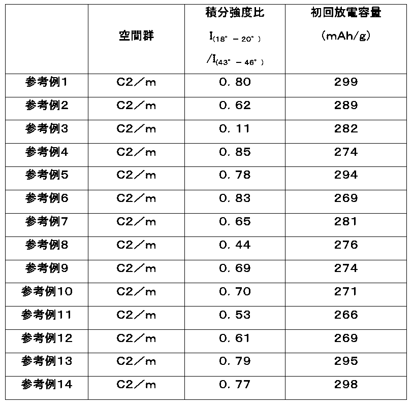
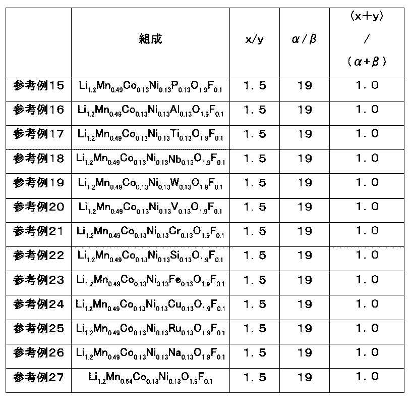

表4~表7に示されるように、参考例1~26の電池は、266~299mAh/gの初回放電容量を有する。
言い換えれば、参考例1~26の電池は、参考例27~31の電池よりも大きな初回放電容量を有する。
この理由としては、参考例1~26の電池では、正極活物質に含まれるリチウム複合酸化物がFを含み、空間群C2/mに属する結晶構造を有し、かつX線回析パターンにおいて0.05以上0.90以下の積分強度比I(18°-20°)/I(43°-46°)を有することが考えられる。すなわち、電気陰性度が高いFによって酸素の一部を置換することで、結晶構造が安定化したと考えられる。さらに、積分強度比I(18°-20°)/I(43°-46°)が0.05以上0.90以下であるので、LiおよびMeのカチオンミキシングが十分に生じる。その結果、隣接するLiの量が増加し、Liの拡散性が向上したと考えられる。これらの効果が総合的に作用することで、初回放電容量が大きく向上したと考えられる。
参考例27では、積分強度比I(18°-20°)/I(43°-46°)が0.90よりも大きいので、カチオンミキシングが抑制されることにより、リチウムの三次元的な拡散経路が減少したと考えられる。その結果、リチウムの拡散が阻害され、初回放電容量が低下したと考えられる。
参考例28では、積分強度比I(18°-20°)/I(43°-46°)が0.05よりも小さいので、熱力学的に結晶構造が不安定となり、充電時のLi脱離に伴い結晶構造が崩壊したと考えられる。その結果、初回放電容量が低下したと考えられる。
参考例29では、リチウム複合酸化物がFを含まないので、結晶構造が不安定となり、充電時のLi脱離に伴い結晶構造が崩壊したと考えられる。その結果、初回放電容量が低下したと考えられる。
表4~表5に示されるように、参考例2の電池は、参考例1の電池よりも小さい初回放電容量を有する。
この理由としては、参考例2の電池は、参考例1の電池よりも、小さい積分強度比I(18°-20°)/I(43°-46°)を有することが考えられる。その結果、結晶構造が不安定となり、初回放電容量が低下したと考えられる。
表4~表5に示されるように、参考例3の電池は、参考例2の電池よりも小さい初回放電容量を有する。
この理由としては、参考例3の電池は、参考例2の電池よりも、小さい積分強度比I(18°-20°)/I(43°-46°)を有することが考えられる。その結果、結晶構造が不安定となり、初回放電容量が低下したと考えられる。
表4~表5に示されるように、参考例4の電池は、参考例1の電池よりも小さい初回放電容量を有する。
この理由としては、参考例4の電池は、参考例1の電池よりも、大きな積分強度比I(18°-20°)/I(43°-46°)を有することが考えられる。このため、カチオンミキシングが抑制されることにより、リチウムの三次元的な拡散経路がわずかに減少したと考えられる。その結果、リチウムの拡散が阻害され、初回放電容量が低下したと考えられる。
表4~表5に示されるように、参考例5の電池は、参考例1の電池よりも小さい初回放電容量を有する。
この理由としては、参考例5の電池は、参考例1の電池よりも、大きな(α/β)の値を有することが考えられる。すなわち、酸素の酸化還元による容量が過剰となること、および電気陰性度が高いFの影響が小さくなり、Liが脱離した際に結晶構造が不安定化したことが考えられる。その結果、初回放電容量が低下したと考えられる。
表4~表5に示されるように、参考例6の電池は、参考例1の電池よりも小さい初回放電容量を有する。
この理由としては、参考例6の電池は、参考例1の電池よりも、小さな(α/β)の値を有することが考えられる。すなわち、酸素の酸化還元による電荷補償量が低下すること、および電気陰性度が高いFの影響が大きくなり、電子伝導性が低下したことが考えられる。このため、初回放電容量が低下したと考えられる。
表4~表5に示されるように、参考例7~参考例9の電池は、参考例1の電池よりも小さい初回放電容量を有する。
この理由としては、参考例7~9の電池は、参考例1の電池とは異なり、結晶構造を安定化させる効果およびLiの脱離を促進させる効果をそれぞれ有するCoおよびNiからなる群から選択される少なくとも1つを含まないことが考えられる。その結果、初回放電容量が低下したと考えられる。
表4~表5に示されるように、参考例10の電池は、参考例1の電池よりも小さい初回放電容量を有する。
この理由としては、参考例10の電池は、参考例1の電池よりも、大きな(x/y)の値を有することが考えられる。このため、電池の初回充電において、結晶構造内のLiが多く引き抜かれ、結晶構造が不安定化したことが考えられる。さらに、結晶構造の不安定化が原因で、放電で挿入されるLi量が低下したと考えられる。その結果、初回放電容量が低下したと考えられる。
表4~表5に示されるように、参考例11の電池は、参考例1の電池よりも小さい初回放電容量を有する。
この理由としては、参考例11の電池は、参考例10の電池よりも、大きな(x/y)の値を有することが考えられる。このため、電池の初回充電において、結晶構造内のLiが多く引き抜かれ、結晶構造が不安定化したことが考えられる。さらに、結晶構造の不安定化が原因で、放電で挿入されるLi量が低下したと考えられる。その結果、初回放電容量が低下したと考えられる。
表4~表5に示されるように、参考例12の電池は、参考例1の電池よりも小さい初回放電容量を有する。
この理由としては、参考例11の電池は、参考例10の電池よりも、小さな(x/y)の値を有することが考えられる。このため、反応に関与できるLiの量が少なくなり、Liイオンの拡散性が低下したことが考えられる。その結果、初回放電容量が低下したと考えられる。
表4~表7に示されるように、参考例13~26の電池は、参考例1の電池よりも小さい初回放電容量を有する。
この理由としては、参考例13~26の電池では、参考例1の電池よりも、酸素との軌道混成をしやすいMnの量が少ないことが考えられる。このため、酸素の酸化還元反応への寄与が僅かに低下し、初回放電容量が低下したと考えられる。
本開示の正極活物質は、二次電池のような電池の正極活物質として、利用されうる。
10 電池
11 ケース
12 正極集電体
13 正極活物質層
14 セパレータ
15 封口板
16 負極集電体
17 負極活物質層
18 ガスケット
21 正極
22 負極
11 ケース
12 正極集電体
13 正極活物質層
14 セパレータ
15 封口板
16 負極集電体
17 負極活物質層
18 ガスケット
21 正極
22 負極
Claims (23)
- 正極活物質であって、
第一リチウム複合酸化物、および
前記第一リチウム複合酸化物の表面の少なくとも一部を被覆する第二リチウム複合酸化物
を具備し、
ここで、
第一リチウム複合酸化物は、F、Cl、N、およびSからなる群より選択される少なくとも1つを含有し、
第一リチウム複合酸化物は、層状構造に属する結晶構造を有し、
前記第二リチウム複合酸化物は、空間群Fd-3mに属する結晶構造を有し、かつ
以下の数式(I)が充足される、
0.05≦積分強度比I(18°-20°)/I(43°-46°)≦0.90 (I)
ここで、
積分強度比I(18°-20°)/I(43°-46°)は、積分強度I(43°-46°)に対する積分強度I(18°-20°)の比に等しく、
積分強度I(18°-20°)は、前記正極活物質のX線回析パターンにおいて、18°以上20°以下の回折角2θの範囲に存在する最大ピークである第一ピークの積分強度であり、かつ
積分強度I(43°-46°)は、前記正極活物質のX線回析パターンにおいて、43°以上46°以下の回折角2θの範囲に存在する最大ピークである第二ピークの積分強度である、
正極活物質。 - 請求項1に記載の正極活物質であって、
前記積分強度比I(18°-20°)/I(43°-46°)が、0.11以上0.85以下である
正極活物質。 - 請求項2に記載の正極活物質であって、
前記積分強度比I(18°-20°)/I(43°-46°)が、0.44以上0.85以下である、
正極活物質。 - 請求項3に記載の正極活物質であって、
前記積分強度比I(18°-20°)/I(43°-46°)が、0.55以上0.59以下である、
正極活物質。 - 請求項1から4のいずれか一項に記載の正極活物質であって、
前記第一リチウム複合酸化物の結晶構造は、空間群C2/mおよび空間群R-3mからなる群より選択される少なくとも1つに属する、
正極活物質。 - 請求項5に記載の正極活物質であって、
前記第一リチウム複合酸化物の結晶構造は、空間群C2/mに属する、
正極活物質。 - 請求項1から6のいずれか一項に記載の正極活物質であって、
前記X線回析パターンは、63°以上66°以下の回折角2θの範囲に2つ以上のピークを有する、
正極活物質。 - 請求項7に記載の正極活物質であって、
以下の数式(II)が充足される、
1.18≦積分強度比I(63°-65°)/I(65°-66°)≦2.0 (II)
ここで、
積分強度比I(63°-65°)/I(65°-66°)は、積分強度I(65°-66°)に対する積分強度I(63°-65°)の比に等しく、
積分強度I(65°-66°)は、前記正極活物質のX線回析パターンにおいて、65°以上66°以下の回折角2θの範囲に存在する最大ピークである第三ピークの積分強度であり、かつ
積分強度I(63°-65°)は、前記正極活物質のX線回析パターンにおいて、63°以上65°以下の回折角2θの範囲に存在する最大ピークである第四ピークの積分強度である、
正極活物質。 - 請求項8に記載の正極活物質であって、
前記積分強度比I(63°-65°)/I(65°-66°)は、1.22以上1.28以下である、
正極活物質。 - 請求項1から9のいずれか一項に記載の正極活物質であって、
前記第二リチウム複合酸化物は、前記第一リチウム複合酸化物の前記表面の少なくとも一部と固溶体を形成している、
正極活物質。 - 請求項1から10のいずれか一項に記載の正極活物質であって、
前記第一リチウム複合酸化物に対する前記第二リチウム複合酸化物のモル比が、50%以下である、
正極活物質。 - 請求項11に記載の正極活物質であって、
前記モル比が、6%以上29%以下である、
正極活物質。 - 請求項1から12のいずれか一項に記載の正極活物質であって、
前記第二リチウム複合酸化物は、0.1ナノメートル以上30ナノメートル以下の厚みを有する、
正極活物質。 - 請求項13に記載の正極活物質であって、
前記厚みは、0.5ナノメートル以上6ナノメートル以下である、
正極活物質。 - 請求項1から14のいずれか一項に記載の正極活物質であって、
前記第一リチウム複合酸化物は、Mnをさらに含有する、
正極活物質。 - 請求項15に記載の正極活物質であって、
前記第一リチウム複合酸化物は、CoおよびNiをさらに含有する、
正極活物質。 - 請求項1から16のいずれか一項に記載の正極活物質であって、
前記第一リチウム複合酸化物は、Fを含有する、
正極活物質。 - 請求項1から14のいずれか一項に記載の正極活物質であって、
前記第一リチウム複合酸化物は、組成式LixMeyOαQβにより表される、正極活物質。
ここで、
Meは、Mn、Co、Ni、Fe、Cu、V、Nb、Mo、Ti、Cr、Zr、Zn、Na、K、Ca、Mg、Pt、Au、Ag、Ru、W、B、Si、P、およびAlからなる群より選択される少なくとも1つであり、
Qは、F、Cl、N、およびSからなる群より選択される少なくとも1つであり、
1.05≦x≦1.4、
0.6≦y≦0.95、
1.33≦α<2、かつ、
0<β≦0.67。 - 請求項18に記載の正極活物質であって、
以下の4つの数式が充足される、正極活物質。
1.15≦x≦1.3、
0.7≦y≦0.85、
1.8≦α≦1.95、かつ
0.05≦β≦0.2。 - 請求項1から19のいずれか一項に記載の正極活物質であって、
前記第一リチウム複合酸化物および前記第二リチウム複合酸化物を、主成分として含む、
正極活物質。 - 電池であって、
請求項1から20のいずれか一項に記載の正極活物質を含む正極、
負極、および
電解質、
を備える、
電池。 - 請求項21に記載の電池であって、
前記負極は、
(i)リチウムイオンを吸蔵および放出可能な負極活物質、および
(ii)材料であって、放電時にリチウム金属が当該材料から電解質に溶解し、かつ充電時に前記リチウム金属が当該材料に析出する材料
からなる群から選択される少なくとも1つを含み、かつ
前記電解質は、非水電解質である、
電池。 - 請求項21に記載の電池であって、
前記負極は、
(i)リチウムイオンを吸蔵および放出可能な負極活物質、および
(ii)材料であって、放電時にリチウム金属が当該材料から電解質に溶解し、かつ充電時に前記リチウム金属が当該材料に析出する材料
からなる群から選択される少なくとも1つを含み、かつ
前記電解質は、固体電解質である、
電池。
Priority Applications (4)
| Application Number | Priority Date | Filing Date | Title |
|---|---|---|---|
| CN201980025822.6A CN111971825B (zh) | 2018-08-31 | 2019-04-22 | 正极活性物质和具备该正极活性物质的电池 |
| EP19855272.1A EP3846261A4 (en) | 2018-08-31 | 2019-04-22 | POSITIVE ELECTRODE ACTIVE MATERIAL AND BATTERY INCLUDING THE LATTER |
| JP2020540048A JP7241359B2 (ja) | 2018-08-31 | 2019-04-22 | 正極活物質およびそれを備えた電池 |
| US17/152,799 US12347858B2 (en) | 2018-08-31 | 2021-01-20 | Positive electrode active material and battery including the same |
Applications Claiming Priority (2)
| Application Number | Priority Date | Filing Date | Title |
|---|---|---|---|
| JP2018163177 | 2018-08-31 | ||
| JP2018-163177 | 2018-08-31 |
Related Child Applications (1)
| Application Number | Title | Priority Date | Filing Date |
|---|---|---|---|
| US17/152,799 Continuation US12347858B2 (en) | 2018-08-31 | 2021-01-20 | Positive electrode active material and battery including the same |
Publications (1)
| Publication Number | Publication Date |
|---|---|
| WO2020044652A1 true WO2020044652A1 (ja) | 2020-03-05 |
Family
ID=69642930
Family Applications (1)
| Application Number | Title | Priority Date | Filing Date |
|---|---|---|---|
| PCT/JP2019/016945 Ceased WO2020044652A1 (ja) | 2018-08-31 | 2019-04-22 | 正極活物質およびそれを備えた電池 |
Country Status (5)
| Country | Link |
|---|---|
| US (1) | US12347858B2 (ja) |
| EP (1) | EP3846261A4 (ja) |
| JP (1) | JP7241359B2 (ja) |
| CN (1) | CN111971825B (ja) |
| WO (1) | WO2020044652A1 (ja) |
Cited By (4)
| Publication number | Priority date | Publication date | Assignee | Title |
|---|---|---|---|---|
| CN111446488A (zh) * | 2020-04-30 | 2020-07-24 | 宁德时代新能源科技股份有限公司 | 一种二次电池及其装置 |
| WO2022239614A1 (ja) * | 2021-05-11 | 2022-11-17 | 株式会社Gsユアサ | 硫化物固体電解質、硫化物固体電解質の製造方法、蓄電素子、電子機器及び自動車 |
| US11508961B2 (en) * | 2017-11-13 | 2022-11-22 | Lg Energy Solution, Ltd. | Method of preparing positive electrode active material for secondary battery |
| EP4269360A4 (en) * | 2020-12-24 | 2024-06-19 | Panasonic Intellectual Property Management Co., Ltd. | POSITIVE ELECTRODE ACTIVE MATERIAL FOR NON-AQUEOUS ELECTROLYTE SECONDARY BATTERIES, AND NON-AQUEOUS ELECTROLYTE SECONDARY BATTERY |
Families Citing this family (1)
| Publication number | Priority date | Publication date | Assignee | Title |
|---|---|---|---|---|
| CN112088454B (zh) * | 2018-09-05 | 2024-11-22 | 松下知识产权经营株式会社 | 正极活性物质和具备该正极活性物质的电池 |
Citations (6)
| Publication number | Priority date | Publication date | Assignee | Title |
|---|---|---|---|---|
| WO2008126364A1 (ja) * | 2007-03-30 | 2008-10-23 | Toda Kogyo Corporation | 非水電解液二次電池用マンガン酸リチウム及びその製造方法、並びに非水電解液二次電池 |
| JP2012234818A (ja) * | 2011-05-04 | 2012-11-29 | Samsung Electronics Co Ltd | 電極活物質、その製造方法及びそれを採用した電極、並びにリチウム電池 |
| US20140367609A1 (en) * | 2013-06-18 | 2014-12-18 | Samsung Sdi Co., Ltd. | Active material for a lithium secondary battery, method of manufacturing the same, electrode including the active material, and lithium secondary battery including the electrode |
| JP2016025009A (ja) * | 2014-07-22 | 2016-02-08 | トヨタ自動車株式会社 | リチウム二次電池用正極活物質およびその利用 |
| JP2016026981A (ja) | 2014-06-27 | 2016-02-18 | 旭硝子株式会社 | リチウム含有複合酸化物およびその製造方法 |
| JP2019029344A (ja) * | 2017-07-27 | 2019-02-21 | パナソニックIpマネジメント株式会社 | 正極活物質、および、電池 |
Family Cites Families (17)
| Publication number | Priority date | Publication date | Assignee | Title |
|---|---|---|---|---|
| JP4061648B2 (ja) * | 2003-04-11 | 2008-03-19 | ソニー株式会社 | 非水電解質二次電池用正極活物質及びそれを用いた非水電解質二次電池 |
| JP2010067437A (ja) * | 2008-09-10 | 2010-03-25 | Sumitomo Chemical Co Ltd | 電極活物質、電極および非水電解質二次電池 |
| KR20110076955A (ko) * | 2008-09-30 | 2011-07-06 | 엔비아 시스템즈 인코포레이티드 | 비용량이 높은 불소 도핑된 리튬 풍부 금속 산화물 양극 배터리 재료 및 상당하는 배터리 |
| CN101853939B (zh) * | 2009-03-31 | 2012-12-26 | 比亚迪股份有限公司 | 一种负极活性材料及其制备方法及电池 |
| CN102751531B (zh) * | 2011-12-30 | 2015-04-22 | 华明电源(深圳)有限公司 | 一种锂离子二次电池 |
| JP5962429B2 (ja) * | 2012-10-22 | 2016-08-03 | ソニー株式会社 | 電池、電池パック、電子機器、電動車両、蓄電装置および電力システム |
| KR101400593B1 (ko) * | 2012-12-06 | 2014-05-27 | 삼성정밀화학 주식회사 | 양극 활물질, 이의 제조방법 및 이를 포함하는 리튬 이차 전지 |
| US9843033B2 (en) | 2013-02-28 | 2017-12-12 | Nissan Motor Co., Ltd. | Positive electrode active substance, positive electrode material, positive electrode, and non-aqueous electrolyte secondary battery |
| EP2784853B1 (en) * | 2013-03-27 | 2018-07-25 | Karlsruher Institut für Technologie | Lithium transistion metal titanate with a spinel structure, method for its manufacturing, its use, Li-ion cell and battery |
| JP2016033902A (ja) * | 2014-07-31 | 2016-03-10 | ソニー株式会社 | 正極活物質、正極および電池 |
| KR102358438B1 (ko) * | 2014-12-30 | 2022-02-04 | 삼성전자주식회사 | 복합 양극 활물질, 그 제조방법, 이를 포함하는 양극 및 리튬이차전지 |
| CN108137347B (zh) * | 2015-10-09 | 2020-07-28 | 住友金属矿山株式会社 | 含锂镍的复合氧化物及其制造方法、非水系电解质二次电池 |
| EP3163656B2 (en) * | 2015-10-28 | 2024-10-23 | Samsung Electronics Co., Ltd. | Composite positive electrode active material, positive electrode including the same, and lithium battery including the positive electrode |
| JP6594202B2 (ja) * | 2015-12-28 | 2019-10-23 | 株式会社オザワエナックス | 高純度・高結晶チタン酸リチウムの製造方法及びこれを用いた高純度・高結晶チタン酸リチウム |
| KR102331069B1 (ko) * | 2016-11-30 | 2021-11-25 | 삼성에스디아이 주식회사 | 복합양극활물질, 이를 포함하는 양극 및 리튬전지 |
| JP7065341B2 (ja) * | 2017-01-19 | 2022-05-12 | パナソニックIpマネジメント株式会社 | 正極活物質、および、電池 |
| JP6952247B2 (ja) * | 2017-01-19 | 2021-10-20 | パナソニックIpマネジメント株式会社 | 正極活物質、および、電池 |
-
2019
- 2019-04-22 EP EP19855272.1A patent/EP3846261A4/en active Pending
- 2019-04-22 CN CN201980025822.6A patent/CN111971825B/zh active Active
- 2019-04-22 JP JP2020540048A patent/JP7241359B2/ja active Active
- 2019-04-22 WO PCT/JP2019/016945 patent/WO2020044652A1/ja not_active Ceased
-
2021
- 2021-01-20 US US17/152,799 patent/US12347858B2/en active Active
Patent Citations (6)
| Publication number | Priority date | Publication date | Assignee | Title |
|---|---|---|---|---|
| WO2008126364A1 (ja) * | 2007-03-30 | 2008-10-23 | Toda Kogyo Corporation | 非水電解液二次電池用マンガン酸リチウム及びその製造方法、並びに非水電解液二次電池 |
| JP2012234818A (ja) * | 2011-05-04 | 2012-11-29 | Samsung Electronics Co Ltd | 電極活物質、その製造方法及びそれを採用した電極、並びにリチウム電池 |
| US20140367609A1 (en) * | 2013-06-18 | 2014-12-18 | Samsung Sdi Co., Ltd. | Active material for a lithium secondary battery, method of manufacturing the same, electrode including the active material, and lithium secondary battery including the electrode |
| JP2016026981A (ja) | 2014-06-27 | 2016-02-18 | 旭硝子株式会社 | リチウム含有複合酸化物およびその製造方法 |
| JP2016025009A (ja) * | 2014-07-22 | 2016-02-08 | トヨタ自動車株式会社 | リチウム二次電池用正極活物質およびその利用 |
| JP2019029344A (ja) * | 2017-07-27 | 2019-02-21 | パナソニックIpマネジメント株式会社 | 正極活物質、および、電池 |
Non-Patent Citations (1)
| Title |
|---|
| See also references of EP3846261A4 |
Cited By (4)
| Publication number | Priority date | Publication date | Assignee | Title |
|---|---|---|---|---|
| US11508961B2 (en) * | 2017-11-13 | 2022-11-22 | Lg Energy Solution, Ltd. | Method of preparing positive electrode active material for secondary battery |
| CN111446488A (zh) * | 2020-04-30 | 2020-07-24 | 宁德时代新能源科技股份有限公司 | 一种二次电池及其装置 |
| EP4269360A4 (en) * | 2020-12-24 | 2024-06-19 | Panasonic Intellectual Property Management Co., Ltd. | POSITIVE ELECTRODE ACTIVE MATERIAL FOR NON-AQUEOUS ELECTROLYTE SECONDARY BATTERIES, AND NON-AQUEOUS ELECTROLYTE SECONDARY BATTERY |
| WO2022239614A1 (ja) * | 2021-05-11 | 2022-11-17 | 株式会社Gsユアサ | 硫化物固体電解質、硫化物固体電解質の製造方法、蓄電素子、電子機器及び自動車 |
Also Published As
| Publication number | Publication date |
|---|---|
| JPWO2020044652A1 (ja) | 2021-08-10 |
| US12347858B2 (en) | 2025-07-01 |
| CN111971825A (zh) | 2020-11-20 |
| CN111971825B (zh) | 2024-07-30 |
| US20210143424A1 (en) | 2021-05-13 |
| JP7241359B2 (ja) | 2023-03-17 |
| EP3846261A4 (en) | 2021-11-17 |
| EP3846261A1 (en) | 2021-07-07 |
Similar Documents
| Publication | Publication Date | Title |
|---|---|---|
| US11271200B2 (en) | Positive-electrode active material containing lithium composite oxide, and battery including the same | |
| US11557760B2 (en) | Positive-electrode active material containing lithium composite oxide, and battery including the same | |
| US11605814B2 (en) | Positive-electrode active material containing lithium composite oxide, and battery including the same | |
| JP6979594B2 (ja) | 正極活物質、および、電池 | |
| JP2018116930A (ja) | 正極活物質、および、電池 | |
| US11233237B2 (en) | Positive electrode active material containing lithium composite oxide and battery including the same | |
| WO2020044653A1 (ja) | 正極活物質およびそれを備えた電池 | |
| JPWO2018092359A1 (ja) | 電池用正極活物質、および、電池 | |
| US12347858B2 (en) | Positive electrode active material and battery including the same | |
| JP2018085324A (ja) | 電池用正極活物質、および、電池用正極活物質を用いた電池 | |
| WO2020049803A1 (ja) | 正極活物質およびそれを備えた電池 | |
| WO2020049793A1 (ja) | 正極活物質およびそれを備えた電池 | |
| WO2020049794A1 (ja) | 正極活物質およびそれを備えた電池 | |
| JP7142302B2 (ja) | 正極活物質およびそれを備えた電池 | |
| WO2019230149A1 (ja) | 正極活物質およびそれを備えた電池 | |
| WO2020049792A1 (ja) | 正極活物質およびそれを備えた電池 | |
| WO2020012739A1 (ja) | 正極活物質およびそれを備えた電池 |
Legal Events
| Date | Code | Title | Description |
|---|---|---|---|
| 121 | Ep: the epo has been informed by wipo that ep was designated in this application |
Ref document number: 19855272 Country of ref document: EP Kind code of ref document: A1 |
|
| ENP | Entry into the national phase |
Ref document number: 2020540048 Country of ref document: JP Kind code of ref document: A |
|
| NENP | Non-entry into the national phase |
Ref country code: DE |
|
| ENP | Entry into the national phase |
Ref document number: 2019855272 Country of ref document: EP Effective date: 20210331 |