WO2020044733A1 - 信号処理装置及び信号処理方法 - Google Patents
信号処理装置及び信号処理方法 Download PDFInfo
- Publication number
- WO2020044733A1 WO2020044733A1 PCT/JP2019/023664 JP2019023664W WO2020044733A1 WO 2020044733 A1 WO2020044733 A1 WO 2020044733A1 JP 2019023664 W JP2019023664 W JP 2019023664W WO 2020044733 A1 WO2020044733 A1 WO 2020044733A1
- Authority
- WO
- WIPO (PCT)
- Prior art keywords
- area
- echo
- weather
- region
- signal processing
- Prior art date
- Legal status (The legal status is an assumption and is not a legal conclusion. Google has not performed a legal analysis and makes no representation as to the accuracy of the status listed.)
- Ceased
Links
Images



Classifications
-
- G—PHYSICS
- G01—MEASURING; TESTING
- G01S—RADIO DIRECTION-FINDING; RADIO NAVIGATION; DETERMINING DISTANCE OR VELOCITY BY USE OF RADIO WAVES; LOCATING OR PRESENCE-DETECTING BY USE OF THE REFLECTION OR RERADIATION OF RADIO WAVES; ANALOGOUS ARRANGEMENTS USING OTHER WAVES
- G01S13/00—Systems using the reflection or reradiation of radio waves, e.g. radar systems; Analogous systems using reflection or reradiation of waves whose nature or wavelength is irrelevant or unspecified
- G01S13/02—Systems using reflection of radio waves, e.g. primary radar systems; Analogous systems
- G01S13/50—Systems of measurement based on relative movement of target
- G01S13/52—Discriminating between fixed and moving objects or between objects moving at different speeds
- G01S13/522—Discriminating between fixed and moving objects or between objects moving at different speeds using transmissions of interrupted pulse modulated waves
- G01S13/524—Discriminating between fixed and moving objects or between objects moving at different speeds using transmissions of interrupted pulse modulated waves based upon the phase or frequency shift resulting from movement of objects, with reference to the transmitted signals, e.g. coherent MTi
- G01S13/5248—Discriminating between fixed and moving objects or between objects moving at different speeds using transmissions of interrupted pulse modulated waves based upon the phase or frequency shift resulting from movement of objects, with reference to the transmitted signals, e.g. coherent MTi combining a coherent MTI processor with a zero Doppler processing channel and a clutter mapped memory, e.g. MTD (Moving target detector)
-
- G—PHYSICS
- G01—MEASURING; TESTING
- G01S—RADIO DIRECTION-FINDING; RADIO NAVIGATION; DETERMINING DISTANCE OR VELOCITY BY USE OF RADIO WAVES; LOCATING OR PRESENCE-DETECTING BY USE OF THE REFLECTION OR RERADIATION OF RADIO WAVES; ANALOGOUS ARRANGEMENTS USING OTHER WAVES
- G01S13/00—Systems using the reflection or reradiation of radio waves, e.g. radar systems; Analogous systems using reflection or reradiation of waves whose nature or wavelength is irrelevant or unspecified
- G01S13/02—Systems using reflection of radio waves, e.g. primary radar systems; Analogous systems
- G01S13/06—Systems determining position data of a target
- G01S13/08—Systems for measuring distance only
- G01S13/10—Systems for measuring distance only using transmission of interrupted, pulse modulated waves
- G01S13/18—Systems for measuring distance only using transmission of interrupted, pulse modulated waves wherein range gates are used
-
- G—PHYSICS
- G01—MEASURING; TESTING
- G01S—RADIO DIRECTION-FINDING; RADIO NAVIGATION; DETERMINING DISTANCE OR VELOCITY BY USE OF RADIO WAVES; LOCATING OR PRESENCE-DETECTING BY USE OF THE REFLECTION OR RERADIATION OF RADIO WAVES; ANALOGOUS ARRANGEMENTS USING OTHER WAVES
- G01S13/00—Systems using the reflection or reradiation of radio waves, e.g. radar systems; Analogous systems using reflection or reradiation of waves whose nature or wavelength is irrelevant or unspecified
- G01S13/02—Systems using reflection of radio waves, e.g. primary radar systems; Analogous systems
- G01S13/50—Systems of measurement based on relative movement of target
- G01S13/52—Discriminating between fixed and moving objects or between objects moving at different speeds
- G01S13/522—Discriminating between fixed and moving objects or between objects moving at different speeds using transmissions of interrupted pulse modulated waves
- G01S13/524—Discriminating between fixed and moving objects or between objects moving at different speeds using transmissions of interrupted pulse modulated waves based upon the phase or frequency shift resulting from movement of objects, with reference to the transmitted signals, e.g. coherent MTi
- G01S13/53—Discriminating between fixed and moving objects or between objects moving at different speeds using transmissions of interrupted pulse modulated waves based upon the phase or frequency shift resulting from movement of objects, with reference to the transmitted signals, e.g. coherent MTi performing filtering on a single spectral line and associated with one or more range gates with a phase detector or a frequency mixer to extract the Doppler information, e.g. pulse Doppler radar
-
- G—PHYSICS
- G01—MEASURING; TESTING
- G01S—RADIO DIRECTION-FINDING; RADIO NAVIGATION; DETERMINING DISTANCE OR VELOCITY BY USE OF RADIO WAVES; LOCATING OR PRESENCE-DETECTING BY USE OF THE REFLECTION OR RERADIATION OF RADIO WAVES; ANALOGOUS ARRANGEMENTS USING OTHER WAVES
- G01S13/00—Systems using the reflection or reradiation of radio waves, e.g. radar systems; Analogous systems using reflection or reradiation of waves whose nature or wavelength is irrelevant or unspecified
- G01S13/02—Systems using reflection of radio waves, e.g. primary radar systems; Analogous systems
- G01S13/50—Systems of measurement based on relative movement of target
- G01S13/58—Velocity or trajectory determination systems; Sense-of-movement determination systems
- G01S13/581—Velocity or trajectory determination systems; Sense-of-movement determination systems using transmission of interrupted pulse modulated waves and based upon the Doppler effect resulting from movement of targets
- G01S13/582—Velocity or trajectory determination systems; Sense-of-movement determination systems using transmission of interrupted pulse modulated waves and based upon the Doppler effect resulting from movement of targets adapted for simultaneous range and velocity measurements
-
- G—PHYSICS
- G01—MEASURING; TESTING
- G01S—RADIO DIRECTION-FINDING; RADIO NAVIGATION; DETERMINING DISTANCE OR VELOCITY BY USE OF RADIO WAVES; LOCATING OR PRESENCE-DETECTING BY USE OF THE REFLECTION OR RERADIATION OF RADIO WAVES; ANALOGOUS ARRANGEMENTS USING OTHER WAVES
- G01S13/00—Systems using the reflection or reradiation of radio waves, e.g. radar systems; Analogous systems using reflection or reradiation of waves whose nature or wavelength is irrelevant or unspecified
- G01S13/88—Radar or analogous systems specially adapted for specific applications
- G01S13/95—Radar or analogous systems specially adapted for specific applications for meteorological use
-
- G—PHYSICS
- G01—MEASURING; TESTING
- G01W—METEOROLOGY
- G01W1/00—Meteorology
- G01W1/10—Devices for predicting weather conditions
-
- Y—GENERAL TAGGING OF NEW TECHNOLOGICAL DEVELOPMENTS; GENERAL TAGGING OF CROSS-SECTIONAL TECHNOLOGIES SPANNING OVER SEVERAL SECTIONS OF THE IPC; TECHNICAL SUBJECTS COVERED BY FORMER USPC CROSS-REFERENCE ART COLLECTIONS [XRACs] AND DIGESTS
- Y02—TECHNOLOGIES OR APPLICATIONS FOR MITIGATION OR ADAPTATION AGAINST CLIMATE CHANGE
- Y02A—TECHNOLOGIES FOR ADAPTATION TO CLIMATE CHANGE
- Y02A90/00—Technologies having an indirect contribution to adaptation to climate change
- Y02A90/10—Information and communication technologies [ICT] supporting adaptation to climate change, e.g. for weather forecasting or climate simulation
Definitions
- the present invention relates to a signal processing device and a signal processing method that can easily restore an attenuated zero Doppler weather echo.
- an observation device that uses waves such as electromagnetic waves and sound waves to measure the distance and speed of a remotely located target or object, remove unnecessary waves, and accurately measure the target object.
- waves such as electromagnetic waves and sound waves to measure the distance and speed of a remotely located target or object, remove unnecessary waves, and accurately measure the target object.
- a pulse Doppler technique using a radar device, a lidar (lightwave radar) device, a soda (sonic wave radar) device, or the like is known.
- Some pulse Doppler techniques use or remove echoes outside the basic sweep period (outside the range of distance measurements).
- the pulse Doppler technology is also used in observation devices (measurement devices) such as weather radar devices that use a target as precipitation particles (raindrops).
- a weather radar device (particularly, a pulse Doppler radar device) will be described as an example of an observation device.
- the signal processing device and the signal processing method according to the present application are not limited to application to a weather radar device using electromagnetic waves. It can be applied to observation devices for observing weather.
- a meteorological radar device emits pulsed electromagnetic waves into space, receives reflected waves scattered by meteorological particles (precipitation particles), which are targets in the space, and performs signal processing on the received signal to perform target processing.
- meteorological particles precipitation particles
- a terrain echo also called ground clutter
- a terrain echo in a short distance may be captured by the side lobe of the beam.
- the side lobe may be captured on the terrain at a short distance.
- the terrain echo is mixed, two peaks due to the terrain and precipitation appear on the Doppler spectrum, and the terrain echo not only apparently shifts the Doppler velocity of precipitation (weather echo) to zero, but also has a prominent power. Therefore, the intensity (electric power), that is, the intensity of rainfall is also overestimated. Therefore, it is necessary to remove the terrain echo.
- the process of removing the terrain echo is generally called MTI (Moving @ Target @ Indicator).
- a method of MTI there is a method of removing a topographic echo signal using a low-frequency filtering filter of a time-series phase difference signal by utilizing a property that a Doppler velocity is concentrated in a low-frequency region near zero. It is also generally known to remove Doppler velocity near zero on the Doppler spectrum and interpolate the removal area with surrounding signals to recover weather echo near Doppler velocity suppressed together with terrain echo. Have been.
- texture the amount of spatial fluctuation
- the terrain echo is larger than the meteorological echo
- the terrain echo signal phase accumulation variation
- a method that utilizes a property that is greater than the accumulation of weather echo phases for example, see Non-Patent Document 1.
- a zero-Doppler region As a method to avoid erroneous suppression when the Doppler velocity is close to zero and the spectral width is narrow like a terrain echo, the area where the Doppler velocity observed at two different times is near zero (hereinafter referred to as , A zero-Doppler region) is used to specify a zero-Doppler region and suppress the attenuation of weather echoes in the zero-Doppler region (for example, see Patent Document 2).
- Patent Document 2 has a problem that the zero Doppler region cannot be specified unless the zero Doppler region fluctuates between two times, and the zero Doppler is attenuated by the terrain echo removal processing.
- the present invention has been made to solve the above-described problem, and relates to a signal processing device and a signal processing method that can easily restore a zero Doppler weather echo attenuated by terrain echo removal processing.
- a signal processing apparatus and a signal processing method are characterized in that a pulse wave is repeatedly transmitted to a space, and a reception signal of a reflected wave of the pulse wave reflected, a Doppler spectrum derived from the reception signal, and a topography from the Doppler spectrum.
- the first weather echo region is obtained from the spectrum after the terrain echo removal from which the echo has been removed, of the weather parameters having different behaviors between the weather echo and the terrain echo, and the behavior of the weather parameter does not correspond to the Doppler velocity.
- a second weather echo area is obtained by using the dependent weather or a weather echo area having a Doppler velocity of zero is obtained by using the weather parameter, and the first weather echo area and the second weather echo area are obtained from the first weather echo area.
- a weather echo area from the first weather echo area and the zero Doppler velocity weather echo area Determination is characterized in that.
- the weather echo region is determined by using the characteristics of the weather parameter, and the terrain echo is removed by the terrain echo removal processing, that is, the weather echo of erroneously suppressed zero Doppler is restored.
- the weather echo of erroneously suppressed zero Doppler is restored.
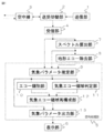
- FIG. 3 is a functional block diagram of a signal processing device according to Embodiments 1 and 2 of the present invention.
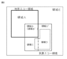
- FIG. 3 is a schematic diagram illustrating an example of an observation area of an observation device to which the signal processing device and the signal processing method according to Embodiments 1 to 3 of the present invention are applied.
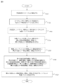
- 4 is a flowchart of a signal processing method according to Embodiment 1 of the present invention.
- FIG. 4 is a schematic diagram illustrating an example of echo classification in the signal processing device and the signal processing method according to Embodiments 1 to 3 of the present invention.
- 9 is a flowchart of a signal processing method according to Embodiment 2 of the present invention.
- FIG. 13 is a functional block diagram of a signal processing device according to Embodiment 3 of the present invention. 13 is a flowchart of a signal processing method according to Embodiment 3 of the present invention.
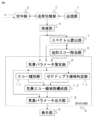
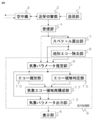
- FIG. 3 is a functional block diagram of a signal processing device according to Embodiments 1 to 3 of
- FIG. 1 is a functional block diagram of a weather radar device (observation device, measurement device) to which the signal processing device according to the first embodiment is applied.
- the present application can be implemented with a functional block configuration different from that in FIG. That is, what is shown in FIG. 1 is an example of a block configuration.
- the same reference numerals indicate the same or corresponding parts, and detailed description thereof may be omitted.
- a weather radar device to which the signal processing device according to the first embodiment is applied includes a transmission unit 1, a transmission / reception switching unit 2, an antenna unit 3 (antenna unit 3), a reception unit 4, and a signal processing unit 5 (signal processing unit).
- the unit 5 includes a signal processing device according to the present application). These can be said to be the weather radar devices according to the first embodiment.
- the observation device (measuring device) according to the first embodiment includes a transmission unit 1, a transmission / reception switching unit 2, an antenna unit 3 (antenna unit 3) or an optical scanner unit 3 or a sound wave speaker unit 3, a reception unit 4, It can be said that the processing unit 5 (the signal processing device according to the present application) is provided.
- the antenna unit 3 (antenna unit 3), the optical scanner unit 3, or the sound wave speaker unit 3 can be said to be a wave transmitting / receiving unit 3.
- the transmission / reception of such a wave transmission / reception unit 3 may be separate.
- the transmission unit 1 generates a reference signal as a source of a transmission wave, and performs pulse modulation on the reference signal, phase modulation such that the initial phase changes for each transmission, frequency conversion, and amplification.
- the transmission / reception switching unit 2 outputs a pulse wave which is a transmission wave generated by the transmission unit 1 to the antenna unit 3 and takes in a reception wave from the antenna unit 3.
- the antenna unit 3 radiates a pulse wave to a space as a transmission wave, and acquires a radio wave (reflection wave) arriving after being reflected by an object existing in the space as a reception wave (reflection wave).
- the receiving unit 4 receives the reception wave received by the antenna unit 3 and passed through the transmission / reception switching unit 2, converts the frequency, amplifies the reception wave, and detects the reception wave to thereby receive a reception signal (a reception signal of a reflected wave of a pulse wave). Is generated and sent to the signal processing unit 5.
- the signal processing device 5 is the signal processing device according to the first embodiment.
- the signal processing device 5 includes a spectrum calculation unit 7, a terrain echo removal unit 8, a weather parameter estimation unit 9, an echo classification unit 10, a weather echo area determination unit 11 (echo area determination unit 11), a weather echo area reconstruction unit 12, It has a weather parameter output unit 13.
- the spectrum calculation unit 7 and the terrain echo removal unit 8 may be provided outside the signal processing device 5.
- the display unit 6 displays weather parameters in a range cell corresponding to a weather echo area (determined by the weather echo area reconstruction unit 12) output from the signal processing device 5 (weather parameter output unit 13) in a predetermined method.
- a display device such as a liquid crystal display.
- the display unit 6 may display the weather parameters output from the weather parameter estimation unit 9 by a predetermined method.
- the spectrum calculation unit 7 performs a Fourier transform on the reception signal generated by the reception unit 4 to generate a Doppler spectrum.
- the terrain echo removal unit 8 estimates and removes the terrain echo.
- the terrain echo removal unit 8 removes a signal near zero Doppler from the Doppler spectrum generated by the spectrum calculation unit 7 and then interpolates around the removed point.
- a Doppler spectrum is generated by performing a removal process and removing a terrain echo.
- the terrain echo removing unit 8 estimates the terrain echo from the Doppler spectrum derived from the received signal of the reflected pulse wave. At this time, it is preferable that the spectral distribution of the terrain echo is estimated by fitting the Doppler spectrum generated by the spectrum calculating unit 7.
- the terrain echo removal unit 8 removes a Doppler spectrum included in the estimated terrain echo spectral distribution.
- a weather parameter estimating unit 9 calculates a received signal of a reflected wave of a pulse wave transmitted and reflected in a repeated space, a Doppler spectrum derived by the spectrum calculating unit 7 from the received signal, and a Doppler spectrum
- the terrain echo removing unit 8 obtains weather parameters from the terrain echo removed spectrum from which the terrain echo has been removed.
- the reception signal (time-series signal) generated by the reception unit 4, the Doppler spectrum generated by the spectrum calculation unit 7, and the Doppler spectrum after the terrain echo removal generated by the terrain echo removal unit 8 will be described later in detail.
- a process for estimating weather parameters such as a phase, a signal intensity (radar reflection factor), and an intensity difference before and after removing a terrain echo is performed.
- the echo classification unit 10 obtains the first weather echo area using weather parameters having different behaviors between the weather echo and the terrain echo. More specifically, using the weather parameter generated by the weather parameter estimating unit 9, whether the signal of each range cell is a weather echo, a terrain echo, a mixture of both, or other noise or determination A process is performed to determine whether it is impossible.
- the weather echo area determination unit 11 (echo area determination unit 11) obtains the second weather echo area using weather parameters whose behavior does not depend on the Doppler velocity. More specifically, a process of determining whether or not the signal of each range cell is a weather echo using weather parameters that do not change with the value of the Doppler velocity among the weather parameters generated by the weather parameter estimation unit 9 is performed.
- the weather echo area reconstruction unit 12 determines the final weather echo area from the first weather echo area and the second weather echo area. More specifically, of the echo classification results generated by the echo classification unit 10, a region determined to be a weather echo (first weather echo region) and a weather echo region generated by the weather echo region determination unit 11 (second weather echo region) The processing of reconstructing the weather echo area using the weather echo area is performed.
- the weather parameter output unit 13 receives the weather parameter generated by the weather parameter estimation unit 9 and the weather echo region generated by the weather echo region reconstruction unit 12 and inputs predetermined weather parameters of an area determined as a weather echo. This is to perform output processing. More specifically, it outputs weather parameters in a range cell corresponding to the weather echo area determined by the weather echo area reconstruction unit 12.
- the pulse wave is repeatedly transmitted to the space, and the received signal of the reflected wave of the reflected pulse wave, the Doppler spectrum derived from the received signal, and the removal of the terrain echo from the Doppler spectrum are removed.
- FIG. 2 is a schematic diagram showing an example of the observation area of the observation device and showing a distribution state of a terrain echo area and a weather echo area.
- a region A is a region where only a terrain echo exists.
- Region B is a region where the weather echo is superimposed on the terrain echo.
- the area B ' is an area in which only the weather echo is obtained as a result of performing the terrain echo removal processing on the area B.
- the area C is a weather echo area that becomes zero Doppler.
- the area D is an area classified as a weather echo in the echo classification processing (echo classification step).
- the region D ' is a region of only the weather echo (but not including zero Doppler).
- the region E is a region that does not include a weather echo or a terrain echo, is noise, or cannot be determined.
- the areas A, B (B '), C, and D' do not have a common part (overlap). That is, the area C does not include B (B ').
- the areas A, B (B '), and D do not have a common part (overlap) with each other.
- an area C + area D ′ represents an area determined as a weather echo in the weather echo area determination processing (weather echo area determination step), and an area A + area B represents an original terrain echo area,
- the '+ region C + region D + region D' represents the original weather echo region.
- FIG. 2 illustrates the region D as being included in the region C + region D ′, the region D may include the region C + region D ′.
- the signal processing method according to the first embodiment (the operation of the signal processing device according to the first embodiment) will be described in detail with reference to the flowchart in FIG. Only the steps 14 (ST14) to 16 (ST16) may be used as the signal processing method according to the first embodiment.
- the spectrum calculation step which is step 11 (ST11)
- the spectrum calculation unit 7 performs a Fourier transform on the received signal (time series) for each range cell to calculate a (Doppler) spectrum.
- a terrain echo removal step of step 12 (ST12) is performed.
- the terrain echo removal unit 8 performs terrain echo removal on the spectrum calculated in ST11, and generates a spectrum after terrain echo removal.
- a method of removing the terrain echo in ST12 a method of linearly interpolating both ends of the removed component after removing a component of a predetermined spectral width centering on the Doppler velocity zero on the spectrum, or a method for removing the terrain echo component
- the remaining spectral points are represented by a second Gaussian type spectrum.
- a method can be used in which the fitted and removed spectral points are replaced with points of a second Gaussian-type spectrum.
- a non-regression type low-frequency filtering elliptic filter can be applied to the received signal on the time axis.
- step 13 is a weather parameter estimation step, using the received signal (time series), the spectrum obtained in ST11, and the spectrum obtained after removing the terrain echo obtained in ST12.
- step 13 is a weather parameter estimation step, using the received signal (time series), the spectrum obtained in ST11, and the spectrum obtained after removing the terrain echo obtained in ST12.
- the intensity (power), Doppler velocity, and spectrum width estimated as a spectral moment the amount of phase fluctuation of the received signal within a predetermined space (range, direction), the amount of fluctuation of the intensity, and the Doppler velocity
- the fluctuation amount, the fluctuation amount of the spectrum width, the intensity difference before and after the terrain echo removal processing Clutter ⁇ Suppression ⁇ Ratio; CSR
- the fluctuation amount of the radar reflection factor difference and the phase difference between the polarizations can be used.
- intensity (power) and radar reflection factor are treated synonymously.
- the amount of variation in space is also called a texture parameter, and is calculated as in the following equation (1).
- Table 1 shows examples of typical weather parameters.
- T represents the amount of variation
- y represents the original parameter
- i represents the number in the range direction
- j represents the number in the azimuth direction
- m represents the number of ranges (bins)
- ⁇ represents the average.
- Table 1 describes the behavior when the weather parameter is a terrain echo, the behavior when it is a weather echo (other than zero Doppler), and the behavior when it is a weather echo (zero Doppler).
- the weather parameters may include, for example, CPA (Clutter ⁇ Phase ⁇ Alignment) described in Non-Patent Document 1 in addition to Table 1.
- the echo classification step of step 14 is to obtain a first weather echo area using weather parameters having different behaviors between the weather echo and the terrain echo.
- the echo classifying unit 10 performs the echo classification process using the weather parameters obtained in ST13, and estimates the first weather echo areas (areas B 'and D in FIG. 2).
- FIG. 4 shows an example of the echo classification processing by ST14.
- an evaluation value as a weather echo and an evaluation value as a terrain echo are obtained using at least one or more weather parameters, and the respective evaluation values are compared with predetermined thresholds.
- a meteorological echo region D
- a terrain echo region A
- region D meteorological echo
- region A a meteorological echo region where the meteorological echo is superimposed on the terrain echo or a meteorological echo region where the Doppler velocity is distributed near zero (region B + region) C) or other (area E).
- the area B and the area C often have similar properties and are difficult to be clearly distinguished from each other, hereinafter, an area in which these areas are combined is mixed.
- the first weather echo area includes a terrain echo removal process in an area including only the weather echo (area D) and an area in which the weather echo and the terrain echo are mixed (area B + area C). Is obtained by integrating the area (area B ′) in which only the weather echo is applied. Therefore, although the first weather echo area includes the area C that is not excessively suppressed by the terrain echo removal processing, it is distinguished from the area C in the second weather echo area to be described later. The area C is not specified.
- FIG. 4A is a block diagram of the echo classification processing.
- FIG. 4B is a schematic diagram of a membership function used in the echo classification processing.
- FIG. 4C is a determination example.
- membership is obtained by inputting n weather parameters from the parameter ⁇ i to the parameter ⁇ i + n ⁇ 1 and referring to the corresponding membership functions (those described in FIG. 4B). Find the value MSF ( ⁇ i ). Next, a value obtained by multiplying the membership value MSF ( ⁇ i ) by the corresponding weight coefficient w ( ⁇ i ) is added, and the result is divided by the sum of the weight coefficients to obtain an evaluation value S (evaluation as a weather echo).
- a value Sw and an evaluation value Sc as a terrain echo are obtained, and then a determination is made using a predetermined threshold as in the example of Fig. 4C to obtain an echo classification result.
- a determination method using a decision tree that sequentially compares with a predetermined threshold for each weather parameter and classifies echoes a support vector machine (SVM), a neural network, deep learning, and the like It is also possible to use a judgment method based on machine learning.
- SVM support vector machine
- the weather echo area determination step (echo area determination step) of step 15 (ST15) is for obtaining a second weather echo area using weather parameters whose behavior is independent of Doppler velocity. is there. More specifically, the weather echo area determination unit 11 performs a weather echo area determination process using the weather parameters obtained in ST13, and estimates a second weather echo area (area C and area D 'in FIG. 2). The processing similar to ST14 can be used for the weather echo area determination processing. However, the weather parameter used here does not depend on the behavior of the Doppler velocity, that is, a parameter having the same behavior between zero Doppler and non-zero Doppler is used. In the example of Table 1, the signal intensity fluctuation amount and the radar reflection factor difference fluctuation amount are used.
- the weather echo area reconstruction step determines an area combining the first weather echo area and the second weather echo area as a weather echo area. More specifically, a third weather echo area (area B ′, area C, area D, area D in FIG. 2) is obtained by the union of the first weather echo area obtained in ST14 and the second weather echo area obtained in ST15. D ′) is calculated.
- a determination is made using a weather parameter that allows attenuation of the weather echo (similar in behavior to the terrain echo).
- the first weather echo area includes the range cell of the zero-Doppler weather echo area C although it may be suppressed by the terrain echo removal processing.
- the range cell of the area C overlaps with the range cell of the area C included in the second weather echo area.
- the range cell of the second weather echo that is not affected by the terrain echo removal is selected.
- the range cell in the area D in the first weather echo area may overlap with the range cell in the second weather echo area.
- a range cell in a first weather echo area (area D) that has undergone comparative evaluation with a terrain echo or the like and has high reliability as a weather echo is selected.
- step 17 which is a weather parameter output step, the weather parameter output unit 13 determines whether the third weather echo area (area B ′, area C, area D, area D) is the final weather echo area obtained in ST16. D ′), and outputs the weather parameter (calculated in ST13) of the range cell corresponding to D ′).
- the meteorological echo area determination unit 11 includes at least one of a meteorological parameter, a signal intensity variation, a spectrum width variation, a radar reflection factor difference variation, and a polarization correlation coefficient variation. One can be used.
- the echo classification unit 10 includes, among the weather parameters, a signal strength difference between the Doppler spectrum and the spectrum after the terrain echo removal, a signal strength, a spectrum width, a phase variation, a signal strength variation, and a spectrum. At least one of the width fluctuation amount, the fluctuation amount of the radar reflection factor difference, and the fluctuation amount of the inter-polarization phase difference can be used.
- the signal processing device and the signal processing method according to the first embodiment integrate the determination result of the weather echo region based on the determination performance with high discrimination performance between the weather echo and the terrain echo and the determination result of only the weather echo, Since a typical weather echo area is configured, a zero Doppler weather echo attenuated by the terrain echo removal processing can be restored, and as a result, highly accurate weather parameters can be obtained.
- FIG. 1 A signal processing device and a signal processing method according to Embodiment 2 of the present invention will be described with reference to FIGS. 1, 2, 4, and 5.
- a signal processing method according to the second embodiment will be described with reference to FIG.
- the description of the portions common to the second embodiment and the first embodiment may be omitted.
- the same reference numerals indicate the same or corresponding parts, and detailed description thereof may be omitted.
- the union of the first weather echo area and the second weather echo area is used as the final (third) weather echo area.
- a meteorological echo region in which the attenuation of zero Doppler is reduced can be configured.
- the functional block configuration of the signal processing device according to the second embodiment is the same as that of the first embodiment in FIG.
- the second embodiment is different from the first embodiment in the operations of the echo classification unit 10 and the weather echo area reconstruction unit 12.
- the echo classifying unit 10 (in the echo classifying step) refers to a first mixed area including at least an area where a weather echo and a terrain echo are mixed in the first embodiment.
- the echo classifying unit 10 determines a first mixed area and a first weather echo area in which a weather echo other than the first mixed area exists.
- the meteorological echo area reconstruction unit 12 (meteorological echo area reconstructing step) sets the second mixed area in the first mixed area other than the overlapping area of the first mixed area and the second meteorological echo area as an overlapping area.
- the part corresponding to the second weather echo area (the part that results in a weather echo area with zero Doppler velocity) is defined as the common area, and the area combining the second mixed area and the common area is finally determined. Is determined to be a natural weather echo area.
- the weather echo area reconstructing unit 12 (in the weather echo area reconstructing step) sets the first meteorological echo other than the first mixed area in the area combining the second mixed area and the common area. Is determined as the final weather echo area.
- the area B ' (the mixed areas before the removal of the terrain echo is the area B and the area C, but the area C is attenuated by the removal of the terrain echo, and only the area B' remains) is integrated into the first area. (Area B ′, area D).
- step 24 which is an echo classification step
- at least the weather echo and the terrain echo are mixed using weather parameters having different behaviors between the weather echo and the terrain echo.
- the first mixed area including the area is obtained.
- the area D determined to be only the weather echo is set as the first weather echo area
- the areas B and C which are the mixed areas before the terrain echo removal processing, are set as the first mixed area.
- step 25 (ST25) for obtaining the second weather echo area CD ' is the same as ST15 in FIG.
- step 26 which is a step of reconstructing the weather echo area.
- ST26 sets a portion other than the overlapping region between the first mixed region and the second weather echo region in the first mixed region as a second mixed region, and sets a portion corresponding to the second weather echo region in the overlapping region.
- the common area an area obtained by combining the second mixed area and the common area is determined as a weather echo area.
- a union of the obtained first weather echo areas D is obtained, and third weather echo areas (areas B, C, and D) that are final weather echo areas are generated.
- the value of the second mixed area is replaced with the value after the removal of the terrain echo (the area B becomes the area B 'by this operation), and the third weather echo area (area B', area C) obtained in ST26.
- the weather parameter (calculated in ST23) of the range cell corresponding to the area D) is output (ST27).
- the difference from the third weather echo area (area B ′, area C, area D, area D ′) is whether or not the area includes the area D ′.
- the region D ' is a region extracted based on the spatial variation (texture) of the weather parameter, and has an advantage that it is hardly affected by zero Doppler.
- the possibility that a signal such as a terrain echo or noise is mixed is not zero.
- the third weather obtained by the signal processing device and the signal processing method according to the second embodiment is used.
- the echo area (area B ′, area C, area D) may have higher weather echo detection performance.
- the signal processing device and the signal processing method according to the second embodiment only the weather echo region having zero Doppler is explicitly specified to constitute the final weather echo region. , The attenuation of the weather echo in the zero Doppler region can be avoided, and as a result, highly accurate weather parameters can be obtained.
- the final weather echo region is configured using the weather echo region in which the terrain echo is unlikely to be mixed, the detection of the weather echo region is performed. The performance is improved, and as a result, highly accurate weather parameters can be obtained.
- FIG. 6 is a functional block diagram of a weather radar device (observation device, measurement device) to which the signal processing device according to the third embodiment is applied.
- the present application can be implemented with a functional block configuration different from that in FIG. That is, what is shown in FIG. 3 is an example of a block configuration.
- the description of the parts common to the third embodiment and the first and second embodiments may be omitted.
- the same reference numerals indicate the same or corresponding parts, and detailed description thereof may be omitted.
- a common part of an area determined as a mixed area by the echo classification processing and an area determined as a weather echo area based on the nature of the spatial variation (texture) of the weather echo parameter is consequently zero Doppler. It was extracted as an area.
- the zero Doppler region is directly obtained by using the Doppler velocity as a weather parameter.
- the operation of the echo area determination unit 11 (weather echo area determination unit 11) and the operation of the weather echo area reconstruction unit 12 are different from those of the second embodiment, and the echo area determination unit 11 (weather echo area determination unit 11) ), An echo area determination section 14 (zero Doppler area determination section 14) is provided.
- the zero Doppler region determination unit 14 echo region determination unit 14 is for obtaining a weather echo region with a zero Doppler velocity using weather parameters. Specifically, a region within a range of a predetermined Doppler speed threshold centered on zero Doppler speed, and at least one region of a region having a spectral width within a range of a predetermined spectral width threshold has a Doppler speed of zero.
- the meteorological echo area reconstruction unit 12 generates a first meteorological echo area (strictly speaking, a first mixed area, or a first meteorological echo in which a first mixed area and a weather echo other than the first mixed area exist).
- the weather echo area is determined from the echo area) and the weather echo area having a Doppler velocity of zero.
- the zero Doppler region determination unit 14 illustrated in FIG. 6 performs a process of specifying a zero Doppler speed range cell using the Doppler speed among the weather parameters generated by the weather parameter estimation unit 9. Note that the zero Doppler region also occurs in a region where the Doppler speed has turned back beyond the Nyquist speed and has returned to near zero, so the Doppler speed used here is before the return correction.
- a signal processing method according to the third embodiment (the operation of the signal processing device according to the third embodiment) will be described with reference to FIGS.
- steps 34 (ST34) to 36 (ST36) will be described in detail with reference to the flowchart in FIG. Only the steps 34 (ST34) to 36 (ST36) may be used as the signal processing method according to the third embodiment.
- steps 31 to 34 (ST31 to ST34) are the same processes as steps 21 to 24 (ST21 to ST24) shown in FIG. 5, respectively.
- the zero Doppler region determination step (echo region determination step) of step 35 (ST35) is to obtain a weather echo region having a Doppler velocity of zero using weather parameters.
- the Doppler velocity is within a range of zero plus or minus a predetermined Doppler velocity threshold from the weather parameters obtained in ST33, and / or the spectrum width is within a predetermined spectrum width threshold. Is determined to be a zero Doppler region C.
- the weather echo area reconstruction step which is step 36 (ST36), sets a second mixed area other than the overlapping area of the first mixed area and the weather echo area with a Doppler velocity of zero in the first mixed area,
- the weather echo area having a Doppler velocity of zero is defined as a common area, and an area obtained by combining the second mixed area and the common area is determined as a final weather echo area.
- the third weather echo area (area B, area C, area D) is obtained.
- ST37 is the same as ST27 in FIG. It should be noted that the value of the range cell in the area B is replaced with the value after the removal of the terrain echo (the area B ').
- the estimation accuracy of the zero Doppler region is improved.
- the signal processing device and the signal processing method according to Embodiment 3 specify the zero Doppler region directly from the Doppler velocity, the estimation accuracy of the zero Doppler region is improved, and as a result, a highly accurate weather parameter Can be obtained.
- FIG. 8 is a functional block diagram of a weather radar device (observation device, measurement device) to which the signal processing device according to the first to third embodiments is applied.
- the present application can be implemented with a functional block configuration different from that in FIG. That is, the one shown in FIG. 8 is an example of a block configuration.
- the echo area determination unit 15 has at least one of the functions of the weather echo area determination unit 11 and the zero Doppler area determination unit 14.
- the signal processing apparatus includes a reception signal of a reflected wave of a pulse wave in which a pulse wave is repeatedly transmitted and reflected, a Doppler spectrum derived from the reception signal, A weather parameter estimating unit 9 for obtaining weather parameters from a spectrum obtained by removing a terrain echo from a Doppler spectrum, and a first weather echo area using a weather parameter having a different behavior between a weather echo and a terrain echo.
- An echo classifying unit 11 for obtaining a second meteorological echo region using a weather parameter whose behavior is independent of the Doppler velocity, or Echo area determination unit 14 (zero Doppler area determination) for obtaining a weather echo area with a Doppler velocity of zero using the parameters Unit 14) and the first weather echo area and the second weather echo area, or from the first weather echo area and the weather echo area of zero Doppler velocity, the weather echo area (the third weather echo area) ), And a weather parameter output unit 13 that outputs weather parameters in a range cell corresponding to the weather echo area (third weather echo area) determined by the weather echo area reconstruction unit 12. It can be said that it has.
- the signal processing method includes: an echo classification step of obtaining a first weather echo area using a weather parameter having a different behavior between a weather echo and a terrain echo; Echo area determination step for obtaining a second weather echo area using a behavior that is independent of Doppler velocity (weather echo area determination step), or echo area for obtaining a weather echo area with zero Doppler velocity using weather parameters From the determination step (zero Doppler area determination step) and the first weather echo area and the second weather echo area, or from the first weather echo area and the weather echo area with zero Doppler velocity, the weather echo area (the (3) a weather echo area reconstruction step of determining the weather echo area.
- the signal processing device and the signal processing method according to the first to third embodiments classify whether a target range cell is a weather echo or a terrain echo using a weather parameter derived from a received signal, Since the weather echo is reconstructed so that the terrain echo removal processing is not performed in the weather echo region having zero Doppler, attenuation of the weather echo can be reduced, and highly accurate weather parameter estimation can be performed.
Landscapes
- Engineering & Computer Science (AREA)
- Radar, Positioning & Navigation (AREA)
- Remote Sensing (AREA)
- Physics & Mathematics (AREA)
- Computer Networks & Wireless Communication (AREA)
- General Physics & Mathematics (AREA)
- Environmental & Geological Engineering (AREA)
- Electromagnetism (AREA)
- Spectroscopy & Molecular Physics (AREA)
- Life Sciences & Earth Sciences (AREA)
- Atmospheric Sciences (AREA)
- Biodiversity & Conservation Biology (AREA)
- Ecology (AREA)
- Environmental Sciences (AREA)
- Radar Systems Or Details Thereof (AREA)
Abstract
パルス波動が繰り返し空間に送信され、反射された前記パルス波動の反射波の受信信号、前記受信信号から導出されたドップラスペクトル、前記ドップラスペクトルから地形エコーを除去した地形エコー除去後スペクトルから気象パラメータのうち、気象エコーと地形エコーとで挙動が異なるものを用いて第1の気象エコー領域を求め、前記気象パラメータのうち、挙動がドップラ速度に非依存のものを用いて第2の気象エコー領域を求める、又は、前記気象パラメータを用いてドップラ速度ゼロの気象エコー領域を求め、前記第1の気象エコー領域と前記第2の気象エコー領域とから、又は、前記第1の気象エコー領域と前記ドップラ速度ゼロの気象エコー領域とから、気象エコー領域を決定する。このようにして、地形エコー除去処理により減衰、すなわち、誤って抑圧したゼロドップラの気象エコーを復元することが容易な信号処理装置及び信号処理方法を得る。
Description
この発明は、減衰したゼロドップラの気象エコーを復元することが容易な信号処理装置及び信号処理方法に関するものである。
従来、遠隔に存在する目標や物体の距離及び速度を計測し、不要波を除去し、目標物を精度良く計測するものとして、電磁波や音波などの波動を用いた観測装置(計測装置)がある。このような観測装置(計測装置)においては、レーダ装置、ライダー(光波レーダ)装置、ソーダ(音波レーダ)装置などを使ったパルスドップラの技術が知られている。パルスドップラの技術には、基本掃引周期外(距離計測範囲の外)エコーを使用するもの又は除去するものがある。また、パルスドップラの技術は、目標物を降水粒子(雨粒)とする気象レーダ装置などの観測装置(計測装置)にも使用されている。以降は、気象レーダ装置(特に、パルスドップラレーダ装置)を観測装置の例として説明を行なうが、本願に係る信号処理装置及び信号処理方法は、電磁波を用いた気象レーダ装置への適用に限らず、気象を観測する観測装置に適用できるものである。
気象レーダ装置は、空間にパルス状の電磁波を放射するとともに、空間内の目標物である気象粒子(降水粒子)で散乱された反射波を受信し、受信信号に信号処理を施すことにより、対象の位置や、強度(電力)、ドップラ速度、スペクトル幅等を計測するものとして知られている。気象レーダにおいては、3次元空間を高速かつ高密度に計測する要求があるが、水平に近い仰角で計測すると、多かれ少なかれ地面や山、建造物等からの反射である地形エコー(グランドクラッタとも呼ばれる)が受信される。また、計測する仰角がある程度大きい場合でも、ビームのサイドローブによって近距離の地形エコーが捉えられることがある。
このように、気象レーダ装置においては、仰角が、ある程度大きい場合でもサイドローブが近距離の地形に捉えられることがある。地形エコーが混入するとドップラスペクトル上には地形と降水による二つのピークが出現し、地形エコーは降水(気象エコー)のドップラ速度を見かけ上ゼロ方向にシフトさせるだけでなく、一般に突出した電力を持つことから強度(電力)すなわち雨量強度も過大評価させる。そのため、地形エコーを除去する必要がある。地形エコーを除去する処理は、一般に、MTI(Moving Target Indicator)と呼ばれる。
MTIの手法としては、地形エコーの信号はドップラ速度がゼロ付近の低周波域に集中している性質を利用し、時系列位相差信号の低周波ろ過フィルタを用いて除去する手法がある。また、ドップラスペクトル上でドップラ速度ゼロ付近を除去し、さらに、その除去域を周辺の信号で補間することで地形エコーとともに抑圧されたドップラ速度ゼロ付近の気象エコーの回復を図る手法などが一般に知られている。
全レンジセルに対して、MTIを行うと少なからず気象エコーも減衰させてしまう場合がある。このような場合に対して、クラッタマップと呼ばれる予め地形エコーの位置(レンジセル)を記録したマップを用いて、地形エコーの位置にのみMTIを適用する方式がある。また、特定地点と非特定地点とのいずれであるかを判定して補正値を使う方式(例えば、特許文献1参照)もある。しかし、クラッタマップや特定地点で対処できるのは通常の電波伝搬による位置が不変の地形エコーのみであり、AP(Anomalous Propagation)クラッタと呼ばれる大気条件によって出現位置が変わる異常伝搬による地形エコーには対処ができない。
APクラッタにも対処できる手法としては、受信強度の空間的な変動量(テクスチャと呼ばれる)が、地形エコーは気象エコーよりも大きい性質や、地形エコーの信号の位相の積み上がり方(ばらつき)が気象エコーの位相の積み上がり方に比べて大きい性質などを利用する方式がある(例えば、非特許文献1参照)。この方式では、観測ごとに対象とするレンジセルが地形エコーであるか否かを判定し、地形エコーである場合に限りMTIを適用することで気象エコーの減衰を低減している。このような動的にMTIを適用するか否かを判定する方法でも、気象エコーが地形エコーのようにドップラ速度がゼロ付近で、かつ、スペクトル幅が狭い場合(Zero-Isodopと呼ばれる)には誤って抑圧する場合がある。
気象エコーが地形エコーのようにドップラ速度がゼロ付近で、かつ、スペクトル幅が狭い場合に誤って抑圧することを避ける方式としては、二つの異なる時刻で観測したドップラ速度がゼロ付近の領域(以降、ゼロドップラ領域と称する)の時間的な動きを利用してゼロドップラ領域を特定し、ゼロドップラ領域の気象エコー減衰を抑止するものがある(例えば、特許文献2参照)。
J.C.Hubbert,M.Dixon,and S.M.Ellis,Weather Radar Ground Clutter.Part II:Real-Time Identification and Filtering,J.Atmos.Oceanic Technol.,26,1181-1197,2009.
しかし、特許文献2に開示される方法は、2時刻の間でゼロドップラ領域に変動がなければゼロドップラ領域を特定できず、地形エコー除去処理によりゼロドップラが減衰してしまうという課題があった。
この発明は、上記のような課題を解消するためになされたもので、地形エコー除去処理により減衰したゼロドップラの気象エコーを復元することが容易な信号処理装置及び信号処理方法に関するものである。
この発明に係る信号処理装置及び信号処理方法は、パルス波動が繰り返し空間に送信され、反射された前記パルス波動の反射波の受信信号、前記受信信号から導出されたドップラスペクトル、前記ドップラスペクトルから地形エコーを除去した地形エコー除去後スペクトルから気象パラメータのうち、気象エコーと地形エコーとで挙動が異なるものを用いて第1の気象エコー領域を求め、前記気象パラメータのうち、挙動がドップラ速度に非依存のものを用いて第2の気象エコー領域を求める、又は、前記気象パラメータを用いてドップラ速度ゼロの気象エコー領域を求め、前記第1の気象エコー領域と前記第2の気象エコー領域とから、又は、前記第1の気象エコー領域と前記ドップラ速度ゼロの気象エコー領域とから、気象エコー領域を決定することを特徴とするものである。
以上のように、この発明によれば、気象パラメータの特性を利用して、気象エコー領域を決定することで、地形エコー除去処理により減衰、すなわち、誤って抑圧したゼロドップラの気象エコーを復元すること、すなわち、誤って抑圧させないことが容易な信号処理装置及び信号処理方法を得ることができる。
実施の形態1.
以下、この発明の実施の形態1に係る信号処理装置及び信号処理方法については図1から図4を用いて説明する。特に、実施の形態1に係る信号処理方法については図3を用いて説明する。図1は、実施の形態1に係る信号処理装置を適用した気象レーダ装置(観測装置、計測装置)の機能ブロック図である。図1とは異なる機能ブロックの構成でも本願は実施できる。つまり、図1に示すものは、一例のブロック構成である。本願の図中、同一符号は、同一又は相当部分を示しそれらについての詳細な説明は省略する場合がある。
以下、この発明の実施の形態1に係る信号処理装置及び信号処理方法については図1から図4を用いて説明する。特に、実施の形態1に係る信号処理方法については図3を用いて説明する。図1は、実施の形態1に係る信号処理装置を適用した気象レーダ装置(観測装置、計測装置)の機能ブロック図である。図1とは異なる機能ブロックの構成でも本願は実施できる。つまり、図1に示すものは、一例のブロック構成である。本願の図中、同一符号は、同一又は相当部分を示しそれらについての詳細な説明は省略する場合がある。
図1において、実施の形態1に係る信号処理装置を適用した気象レーダ装置は、送信部1、送受切替部2、空中線部3(アンテナ部3)、受信部4、信号処理部5(信号処理部5は、本願に係る信号処理装置に相当)を備えている。これらが、実施の形態1に係る気象レーダ装置といえる。換言すると、実施の形態1に係る観測装置(計測装置)は、送信部1、送受切替部2、空中線部3(アンテナ部3)又は光スキャナ部3或いは音波スピーカ部3、受信部4、信号処理部5(本願に係る信号処理装置)を備えているといえる。空中線部3(アンテナ部3)又は光スキャナ部3或いは音波スピーカ部3は、波動送出・受入部3といえる。このような波動送出・受入部3は送受が別体でもよい。
図1において、送信部1は、送信波の元となる基準信号を発生し、基準信号にパルス変調、送信ごとに初期位相が変化するような位相変調、周波数変換、増幅を行うものである。送受切替部2は、送信部1で生成された送信波であるパルス波動を空中線部3へと出力するとともに、空中線部3から受信波を取り込むものである。空中線部3は、パルス波動を送信波として空間に放射するとともに、空間中に存在する物体で反射されて到来した電波(反射波動)を受信波(反射波)として取得するものである。受信部4は、空中線部3で受信して送受切替部2を経由した受信波を取り込み、周波数変換、増幅した後、受信波を検波することにより受信信号(パルス波動の反射波の受信信号)を生成し信号処理部5へ送るものである。
図1において、信号処理装置5は、実施の形態1に係る信号処理装置である。信号処理装置5は、スペクトル算出部7、地形エコー除去部8、気象パラメータ推定部9、エコー類別部10、気象エコー領域判定部11(エコー領域判定部11)、気象エコー領域再構成部12、気象パラメータ出力部13を有している。図1に例示するように、スペクトル算出部7及び地形エコー除去部8は、信号処理装置5の外部に設けてもよい。表示部6は、信号処理装置5(気象パラメータ出力部13)から出力された(気象エコー領域再構成部12が決定した)気象エコー領域に相当するレンジセルにおける気象パラメータを予め定められた方法で表示する例えば、液晶ディスプレイなどの表示装置である。表示部6は、気象パラメータ推定部9から出力された気象パラメータを予め定められた方法で表示してもよい。
図1において、スペクトル算出部7は、受信部4で生成された受信信号にフーリエ変換を施し、ドップラスペクトルを生成する。地形エコー除去部8は、地形エコーを推定して除去するもので、スペクトル算出部7で生成されたドップラスペクトルに対し、ゼロドップラ付近の信号を除去し、その後除去された点周辺を補間する地形エコー除去処理を施し、地形エコー除去後のドップラスペクトルを生成するものである。詳しくは、地形エコー除去部8は、反射されたパルス波動の反射波の受信信号から導出されたドップラスペクトルから地形エコーを推定する。このとき、スペクトル算出部7で生成されたドップラスペクトルに対して、地形エコーのスペクトル分布をフィッティングにより推定することが好ましい。地形エコー除去部8は、推定した地形エコーのスペクトル分布に含まれるドップラスペクトルを除去する。
図1において、気象パラメータ推定部9は、パルス波動が繰り返し空間に送信され、反射されたパルス波動の反射波の受信信号、この受信信号からスペクトル算出部7が導出したドップラスペクトル、このドップラスペクトルから地形エコー除去部8が地形エコーを除去した地形エコー除去後スペクトルから気象パラメータを求めるものである。詳しくは、受信部4で生成された受信信号(時系列信号)およびスペクトル算出部7で生成されたドップラスペクトルおよび地形エコー除去部8で生成された地形エコー除去後のドップラスペクトルに対し、後述する位相や信号強度(レーダ反射因子)や地形エコー除去前後の強度差等の気象パラメータを推定する処理を行う。
図1において、エコー類別部10は、気象パラメータのうち、気象エコーと地形エコーとで挙動が異なるものを用いて第1の気象エコー領域を求めるものである。詳しくは、気象パラメータ推定部9で生成された気象パラメータを用いて、各レンジセルの信号が気象エコーであるのか、地形エコーであるのか、両者が混在したものであるのか、それ以外の雑音もしくは判定不能なものであるのか、を判定する処理を行う。気象エコー領域判定部11(エコー領域判定部11)は、気象パラメータのうち、挙動がドップラ速度に非依存のものを用いて第2の気象エコー領域を求めるものである。詳しくは、気象パラメータ推定部9で生成された気象パラメータのうち、ドップラ速度の値によって変化しない気象パラメータを用いて、各レンジセルの信号が気象エコーであるのか否かを判定する処理を行う。
図1において、気象エコー領域再構成部12は、第1の気象エコー領域と第2の気象エコー領域とから、最終的な気象エコー領域と決定するものである。詳しくは、エコー類別部10で生成されたエコー類別結果のうち、気象エコーと判定された領域(第1の気象エコー領域)と、気象エコー領域判定部11で生成された気象エコー領域(第2の気象エコー領域)を用いて気象エコー領域を再構成する処理を行う。気象パラメータ出力部13は、気象パラメータ推定部9で生成された気象パラメータと気象エコー領域再構成部12で生成された気象エコー領域を入力とし、気象エコーと判定された領域の所定の気象パラメータを出力する処理を行うものである。詳しくは、気象エコー領域再構成部12が決定した気象エコー領域に相当するレンジセルにおける気象パラメータを出力するものである。
次に、図2から図4を用いて、実施の形態1に係る信号処理装置(観測装置の主要部である信号処理部5)の動作を説明する。すなわち、実施の形態1に係る信号処理方法を説明する。なお、実施の形態1に係る信号処理方法は、パルス波動が繰り返し空間に送信され、反射されたパルス波動の反射波の受信信号、受信信号から導出されたドップラスペクトル、ドップラスペクトルから地形エコーを除去した地形エコー除去後スペクトルから求められた気象パラメータを用いる信号処理方法である。
図2は、観測装置の観測領域の一例を示し、地形エコー領域および気象エコー領域の分布状況を示す模式図である。図2において、領域Aは、地形エコーのみが存在する領域である。領域Bは、気象エコーが地形エコーに重畳する領域である。領域B’は、領域Bに地形エコー除去処理を行った結果、気象エコーのみとなった領域である。領域Cは、ゼロドップラとなる気象エコー領域である。領域Dは、エコー類別処理(エコー類別ステップ)で気象エコーと類別された領域である。領域D’は気象エコーのみの(ただし、ゼロドップラを含まない)領域である。領域Eは、気象エコーも地形エコーも含まない、もしくは、雑音、もしくは、判定不能な領域である。また、領域A、B(B’)、C、D’は互いに共通部分(重複)を持たない。すなわち、領域CはB(B’)を含まない。また、領域A,B(B’)、Dも互いに共通部分(重複)を持たない。
また、図2において、領域C+領域D’は、気象エコー領域判定処理(気象エコー領域判定ステップ)で気象エコーと判定された領域を表し、領域A+領域Bが本来の地形エコー領域を、領域B’+領域C+領域D+領域D’が、本来の気象エコー領域を表す。なお、図2では、領域Dは領域C+領域D’に包含されるように例示しているが、領域Dが領域C+領域D’を包含する場合も有り得る。
図3のフローチャートを用いて、実施の形態1に係る信号処理方法(実施の形態1に係る信号処理装置の動作)を詳しく説明する。ステップ14(ST14)からステップ16(ST16)のみを実施の形態1に係る信号処理方法としてもよい。ステップ11(ST11)であるスペクトル算出ステップは、スペクトル算出部7が、レンジセル毎に受信信号(時系列)に対してフーリエ変換を施し(ドップラ)スペクトルを算出する。次に、ステップ12(ST12)である地形エコー除去ステップを行う。ST12は、ST11で算出したスペクトルに対し、地形エコー除去部8が、地形エコー除去を行い、地形エコー除去後のスペクトルを生成する。
ST12の地形エコー除去の方法としては、スペクトル上においてドップラ速度ゼロを中心とし、所定のスペクトル幅分の成分を除去した後、除去された成分の両端を線形補間する方法や、地形エコー成分に対してドップラ速度ゼロを中心とした第1のガウシアン型のスペクトルでフィッティングして推定し、その第1のガウシアン型スペクトルに含まれる成分を除去した後、残存するスペクトル点を第2のガウシアン型スペクトルでフィッティングし、除去されたスペクトル点を第2のガウシアン型スペクトルの点に置き換える方法を用いることができる。また、ここでは、地形エコー除去をスペクトル上で行っているが、時間軸上の受信信号に対して非回帰型の低周波ろ過楕円フィルタを適用することもできる。
受信信号(時系列)、ST11で求めたスペクトル、ST12で求めた地形エコー除去後のスペクトルを用いて、気象パラメータ推定ステップであるステップ13(ST13)を気象パラメータ推定部9が行う。気象パラメータとしては、スペクトルモーメントとして推定する強度(電力)、ドップラ速度、スペクトル幅の他、所定空間(レンジ、方位)内の受信信号の位相の変動量、同様に強度の変動量、ドップラ速度の変動量、スペクトル幅の変動量、地形エコー除去処理前後の強度差(Clutter Suppression Ratio;CSR)、さらに、二重偏波レーダの場合には、レーダ反射因子差の変動量、偏波間位相差の変動量、偏波間相関係数の変動量等を用いることができる。
なお、ここでは、強度(電力)とレーダ反射因子は同義的に扱っている。また、空間内の変動量はテクスチャパラメータとも呼ばれ、以下の式(1)のように計算される。代表的な気象パラメータの例を表1に示す。

式(1)において、Tは変動量を、yは元となるパラメータを、iはレンジ方向の番号、jはアジマス方向の番号、mはレンジ(ビン)数を、μは平均を、それぞれ表す。なお、式(1)では演算量低減のためレンジ方向にのみm個の空間の変動量を算出しているが、アジマス方向にも所定数に広げることもできる。
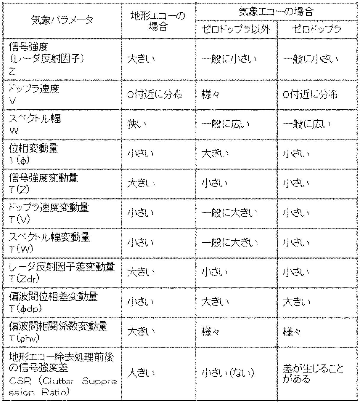
表1では、気象パラメータが地形エコーの場合の挙動、気象エコー(ゼロドップラ以外)の場合の挙動、気象エコー(ゼロドップラ)の場合の挙動を記載している。なお、気象パラメータとしては、表1の他にも、例えば、非特許文献1に記載されているCPA(Clutter Phase Alignment)等を含むことができる。
次に、ステップ14(ST14)であるエコー類別ステップは、気象パラメータのうち、気象エコーと地形エコーとで挙動が異なるものを用いて第1の気象エコー領域を求めるものである。詳しくは、ST13で求めた気象パラメータを用いて、エコー類別部10がエコー類別処理を行い、第1の気象エコー領域(図2における領域B’、領域D)を推定する。
ST14によるエコー類別処理の例を図4に示す。図4のエコー類別処理の例では、少なくとも1つ以上の気象パラメータを用いて気象エコーとしての評価値と地形エコーとしての評価値を求め、それぞれの評価値と所定の閾値との大小比較を行い、それが気象エコー(領域D)であるのか、地形エコー(領域A)であるのか、地形エコーに気象エコーが重畳した領域もしくはドップラ速度がゼロ付近に分布している気象エコー領域(領域B+領域C)であるか、その他(領域E)であるかを決定している。ここで、気象パラメータを用いたエコー類別処理においては、領域Bと領域Cとは性質が類似し明確な区別が困難である場合が多いため、以降、これらの領域を合わせたものを混在した領域とする。また、第1の気象エコー領域(領域B’、領域D)は、気象エコーのみの領域(領域D)と、気象エコーと地形エコーとが混在した領域(領域B+領域C)に地形エコー除去処理を適用して気象エコーのみとなった領域(領域B’)とを統合して得られたものである。よって、第1の気象エコー領域には地形エコー除去処理によって過抑圧されない領域Cが含まれるが、後述する第2の気象エコー領域内の領域Cと区別するため、第1の気象エコー領域中の領域Cは明示しないこととする。
図4(a)は、エコー類別処理のブロック図である。図4(b)は、エコー類別処理で用いるメンバシップ関数の模式図である。図4(c)は、判定例である。図4(a)ではパラメータκiからパラメータκi+n-1のn個の気象パラメータを入力とし、それぞれに対応するメンバシップ関数(図4(b)に記載のもの)を参照することによりメンバシップ値MSF(κi)を求める。次に、メンバシップ値MSF(κi)に対応する重み係数w(κi)を乗じたものを加算し、その結果を重み係数の総和で除すことにより評価値S(気象エコーとしての評価値Sw、地形エコーとしての評価値Scを求める。その後、図4(c)の例のように所定閾値を用いて判定を行い、エコー類別結果を得る。なお、図4ではメンバシップ関数によりエコー類別処理を行う例を示したが、例えば、気象パラメータごとに所定閾値との比較を順に行いエコーを類別する決定木による判定法や、SVM(Support Vector Machine)や、ニューラルネットワークや、深層学習などの機械学習による判定法を用いることもできる。
次に、ステップ15(ST15)である気象エコー領域判定ステップ(エコー領域判定ステップ)は、気象パラメータのうち、挙動がドップラ速度に非依存のものを用いて第2の気象エコー領域を求めるものである。詳しくは、ST13で求めた気象パラメータを用いて、気象エコー領域判定部11が気象エコー領域判定処理を行い、第2の気象エコー領域(図2における領域C、領域D’)を推定する。気象エコー領域判定処理は、ST14と同様の処理を用いることができる。ただし、ここで使用する気象パラメータは、ドップラ速度の挙動に依存しない、すなわち、ゼロドップラとゼロドップラ以外とで挙動が等しいパラメータを用いる。表1の例では、信号強度変動量や、レーダ反射因子差変動量を用いる。
ステップ16(ST16)である気象エコー領域再構成ステップは、第1の気象エコー領域と第2の気象エコー領域とを合わせた領域を気象エコー領域と決定するものである。詳しくは、ST14で求めた第1の気象エコー領域と、ST15で求めた第2の気象エコー領域の和集合により第3の気象エコー領域(図2における領域B’、領域C、領域D、領域D’)を算出する。ST14の第1の気象エコー領域では気象エコー領域から地形エコー領域を確実に除去するために(地形エコーと挙動が類似する)気象エコーの減衰を許容する気象パラメータを用いて判定を行う。一方、ST15の第2の気象エコー領域では気象エコー領域のみを抽出するため、気象エコーと地形エコーとが重畳した領域の抽出が困難である。そこで、両者を統合することでゼロドップラ領域を含んだ本来の気象エコー領域の再現が可能となる。
なお、ステップ16(ST16)において、和集合算出の際、第1の気象エコー領域には地形エコー除去処理により抑圧されている可能性はあるもののゼロドップラの気象エコー領域Cのレンジセルが含まれるためこの領域Cのレンジセルと、第2の気象エコー領域に含まれる領域Cのレンジセルとが重複する。第1の気象エコー内の気象エコーと地形エコー重複領域と、第2の気象エコーのレンジセルとが重複した場合は、地形エコー除去の影響を受けていない第2の気象エコーのレンジセルを選択する。また同様に、第1の気象エコー領域内の領域Dのレンジセルと、第2の気象エコー領域のレンジセルとが重複する可能性がある。この場合は、地形エコー等との比較評価を経ており気象エコーとしての信頼性が高い第1の気象エコー領域(領域D)のレンジセルを選択する。
気象パラメータ出力ステップであるステップ17(ST17)は、気象パラメータ出力部13が、ST16で求めた最終的な気象エコー領域である第3の気象エコー領域(領域B’、領域C、領域D、領域D’)に対応するレンジセルの気象パラメータ(ST13で算出済)を出力する。なお、好ましくは、気象エコー領域判定部11(ST15)は、気象パラメータのうち、信号強度の変動量、スペクトル幅変動量、レーダ反射因子差の変動量、偏波間相関係数の変動量の少なくとも一つを用いることができる。好ましくは、エコー類別部10(ST14)は、気象パラメータのうち、ドップラスペクトルと地形エコー除去後スペクトルとの信号強度差と、信号強度、スペクトル幅、位相の変動量、信号強度の変動量、スペクトル幅変動量、レーダ反射因子差の変動量、偏波間位相差の変動量のうち少なくとも一つとを用いることができる。
以上のように、実施の形態1に係る信号処理装置及び信号処理方法は、気象エコーと地形エコーの弁別性能が高い判定による気象エコー領域の判定結果と、気象エコーのみ判定結果を統合し、最終的な気象エコー領域を構成しているので、地形エコー除去処理により減衰したゼロドップラの気象エコーを復元でき、その結果、精度の高い気象パラメータを得ることができる。
実施の形態2.
この発明の実施の形態2に係る信号処理装置及び信号処理方法については図1、図2、図4、図5を用いて説明する。特に、実施の形態2に係る信号処理方法については図5を用いて説明する。実施の形態2と実施の形態1とで共通の部分は説明を省略する場合がある。本願の図中、同一符号は、同一又は相当部分を示しそれらについての詳細な説明は省略する場合がある。実施の形態1に係る信号処理装置及び信号処理方法では、第1の気象エコー領域と第2の気象エコー領域の和集合を最終的な(第3の)気象エコー領域としていたが、異なる形態によりゼロドップラの減衰を低減した気象エコー領域を構成することもできる。実施の形態2に係る信号処理装置の機能ブロック構成は、実施の形態1と同じく図1である。実施の形態2は、エコー類別部10及び気象エコー領域再構成部12の動作が実施の形態1とは異なる。
この発明の実施の形態2に係る信号処理装置及び信号処理方法については図1、図2、図4、図5を用いて説明する。特に、実施の形態2に係る信号処理方法については図5を用いて説明する。実施の形態2と実施の形態1とで共通の部分は説明を省略する場合がある。本願の図中、同一符号は、同一又は相当部分を示しそれらについての詳細な説明は省略する場合がある。実施の形態1に係る信号処理装置及び信号処理方法では、第1の気象エコー領域と第2の気象エコー領域の和集合を最終的な(第3の)気象エコー領域としていたが、異なる形態によりゼロドップラの減衰を低減した気象エコー領域を構成することもできる。実施の形態2に係る信号処理装置の機能ブロック構成は、実施の形態1と同じく図1である。実施の形態2は、エコー類別部10及び気象エコー領域再構成部12の動作が実施の形態1とは異なる。
実施の形態2に係る信号処理装置では、エコー類別部10が(エコー類別ステップで)、少なくとも気象エコーと地形エコーとが混在する領域を含む第1の混在領域を実施の形態1でいう第1の気象エコー領域として求める。好ましくは、エコー類別部10が(エコー類別ステップで)、第1の混在領域と、第1の混在領域以外の気象エコーが存在する第1の気象エコー領域とを求める。気象エコー領域再構成部12(気象エコー領域再構成ステップ)は、第1の混在領域における第1の混在領域と第2の気象エコー領域との重複領域以外を第2の混在領域とし、重複領域のうち、第2の気象エコー領域に相当する部分(結果的に、ドップラ速度ゼロの気象エコー領域となる部分)を共通領域として、第2の混在領域と共通領域とを合わせた領域を最終的な気象エコー領域と決定する。好ましくは、気象エコー領域再構成部12が(気象エコー領域再構成ステップで)、第2の混在領域と共通領域とを合わせた領域に「第1の混在領域以外の気象エコーが存在する第1の気象エコー領域」を加えた領域を最終的な気象エコー領域と決定する。
図5のフローチャートを用いて、実施の形態2に係る信号処理方法(実施の形態2に係る信号処理装置の動作)を詳しく説明する。ステップ24(ST24)からステップ26(ST26)のみを実施の形態2に係る信号処理方法としてもよい。図5において、ステップ21からステップ23(ST21からST23)は、それぞれ図3に記載のステップ11からステップ13(ST11からST13)と同様の処理である。実施の形態1では、その後のエコー類別部10の処理(図3のST14)では、気象エコーのみと判定された領域Dと、気象エコーと地形エコーの混在領域と判定された領域に対して地形エコー除去を行った結果、領域B’(地形エコー除去前の混在領域は領域B、領域Cであるが、地形エコー除去により領域Cは減衰し領域B’のみが残った)を統合し第1の気象エコー領域(領域B’、領域D)としていた。
一方、実施の形態2では、エコー類別ステップであるステップ24(ST24)は、気象パラメータのうち、気象エコーと地形エコーとで挙動が異なるものを用いて、少なくとも気象エコーと地形エコーとが混在する領域を含む第1の混在領域を求めるものである。詳しくは、ST24では気象エコーのみと判定された領域Dを第1の気象エコー領域とし、地形エコー除去処理前の混在領域である領域B、領域Cを、第1の混在領域とする。その後、第2の気象エコー領域CD’を求めるステップ25(ST25)は図3のST15と同様である。
次に、気象エコー領域再構成ステップであるステップ26(ST26)を行う。ST26は、第1の混在領域における第1の混在領域と第2の気象エコー領域との重複領域以外を第2の混在領域とし、重複領域のうち、第2の気象エコー領域に相当する部分を共通領域として、第2の混在領域と共通領域とを合わせた領域を気象エコー領域と決定するものである。詳しくは、気象エコー領域再構成部12において、ST24で得られた、第1の混在領域(領域B、領域C)と、ST25で得られた第2の気象エコー領域(領域C、領域D’)との共通領域である領域Cを、第1の混在領域(領域B、領域C)から減じて生成した第2の混在領域(領域B)と、共通領域である領域Cと、ST24で得られた第1の気象エコー領域Dの和集合を求め、最終的な気象エコー領域である第3の気象エコー領域(領域B、領域C、領域D)を生成する。最後に、第2の混在領域の値を地形エコー除去後の値に置き換え(この操作で領域Bは領域B’となる)、ST26で求めた第3の気象エコー領域(領域B’、領域C、領域D)に対応するレンジセルの気象パラメータ(ST23で算出済)を出力する(ST27)。
実施の形態2に係る信号処理装置及び信号処理方法で得られる第3の気象エコー領域(領域B’、領域C、領域D)と、実施の形態1に係る信号処理装置及び信号処理方法で得られる第3の気象エコー領域(領域B’、領域C、領域D、領域D’)との違いは、領域D’を含むか否かである。領域D’は気象パラメータの空間的な変動量(テクスチャ)に基づいて抽出された領域であり、ゼロドップラの影響を受けにくい利点はある。しかし、気象エコーとしての性質の有無に基づいた評価のみを行い地形エコーである可能性を排除していないため、地形エコーや雑音等の信号が混入している可能性がゼロではない。したがって、受信信号の信号対雑音電力比が比較的低い場合や、気象エコーと地形エコーの差異が出にくい状況では、実施の形態2に係る信号処理装置及び信号処理方法で得られる第3の気象エコー領域(領域B’、領域C、領域D)の方が、気象エコーの検知性能が高い可能性がある。
以上のように、実施の形態2に係る信号処理装置及び信号処理方法は、ゼロドップラを持つ気象エコー領域のみを明示的に特定し最終的な気象エコー領域を構成しているので、地形エコー除去処理によるゼロドップラ領域の気象エコーの減衰を回避でき、その結果、精度の高い気象パラメータを得ることができる。また、実施の形態2に係る信号処理装置及び信号処理方法は、地形エコーが混入する可能性が低い気象エコー領域を用いて最終的な気象エコー領域を構成しているので、気象エコー領域の検知性能が向上し、その結果、精度の高い気象パラメータを得ることができる。
実施の形態3.
この発明の実施の形態3に係る信号処理装置及び信号処理方法については図2、図4、図6、図7を用いて説明する。特に、実施の形態3に係る信号処理方法については図7を用いて説明する。図6は、実施の形態3に係る信号処理装置を適用した気象レーダ装置(観測装置、計測装置)の機能ブロック図である。図3とは異なる機能ブロックの構成でも本願は実施できる。つまり、図3に示すものは、一例のブロック構成である。実施の形態3と実施の形態1及び2とで共通の部分は説明を省略する場合がある。本願の図中、同一符号は、同一又は相当部分を示しそれらについての詳細な説明は省略する場合がある。実施の形態2では、エコー類別処理によって混在領域と判定された領域と、気象エコーパラメータの空間的変動(テクスチャ)の性質に基づいて気象エコー領域と判定された領域の共通部分を結果的にゼロドップラ領域として抽出していた。実施の形態3では、ゼロドップラ領域を、気象パラメータとしてドップラ速度を用いることで直接得るものである。
この発明の実施の形態3に係る信号処理装置及び信号処理方法については図2、図4、図6、図7を用いて説明する。特に、実施の形態3に係る信号処理方法については図7を用いて説明する。図6は、実施の形態3に係る信号処理装置を適用した気象レーダ装置(観測装置、計測装置)の機能ブロック図である。図3とは異なる機能ブロックの構成でも本願は実施できる。つまり、図3に示すものは、一例のブロック構成である。実施の形態3と実施の形態1及び2とで共通の部分は説明を省略する場合がある。本願の図中、同一符号は、同一又は相当部分を示しそれらについての詳細な説明は省略する場合がある。実施の形態2では、エコー類別処理によって混在領域と判定された領域と、気象エコーパラメータの空間的変動(テクスチャ)の性質に基づいて気象エコー領域と判定された領域の共通部分を結果的にゼロドップラ領域として抽出していた。実施の形態3では、ゼロドップラ領域を、気象パラメータとしてドップラ速度を用いることで直接得るものである。
実施の形態3は、エコー領域判定部11(気象エコー領域判定部11)及び気象エコー領域再構成部12の動作が実施の形態2とは異なり、エコー領域判定部11(気象エコー領域判定部11)に代えて、エコー領域判定部14(ゼロドップラ領域判定部14)を備えている。図7において、ゼロドップラ領域判定部14(エコー領域判定部14)は、気象パラメータを用いてドップラ速度ゼロの気象エコー領域を求めるものである。詳しくは、ドップラ速度ゼロを中心とした予め定められたドップラ速度閾値の範囲内にある領域、及び、スペクトル幅が所定のスペクトル幅閾値の範囲内にある領域の少なくとも一方の領域をドップラ速度ゼロの気象エコー領域として求めるものである。気象エコー領域再構成部12は、第1の気象エコー領域(厳密には、第1の混在領域、又は、第1の混在領域及び第1の混在領域以外の気象エコーが存在する第1の気象エコー領域)とドップラ速度ゼロの気象エコー領域とから、気象エコー領域を決定するものである。
図6に示すゼロドップラ領域判定部14は、気象パラメータ推定部9で生成された気象パラメータのうちドップラ速度を用いて、ゼロドップラ速度のレンジセルを特定する処理を行う。なお、ゼロドップラ領域は、ドップラ速度がナイキスト速度を超えて折り返して再びゼロ付近になった領域でも生じることから、ここで用いるドップラ速度は折り返し補正前のものとする。次に、図6および図7を用いて、実施の形態3に係る信号処理方法(実施の形態3に係る信号処理装置の動作)を説明する。
図7のフローチャートを用いて、実施の形態3に係る信号処理方法(実施の形態3に係る信号処理装置の動作)を詳しく説明する。ステップ34(ST34)からステップ36(ST36)のみを実施の形態3に係る信号処理方法としてもよい。図7において、ステップ31からステップ34(ST31からST34)は、それぞれ図5に記載のステップ21からステップ24(ST21からST24)と同様の処理である。ステップ35(ST35)であるゼロドップラ領域判定ステップ(エコー領域判定ステップ)は、気象パラメータを用いてドップラ速度ゼロの気象エコー領域を求めるものである。詳しくは、ゼロドップラ領域判定部14において、ST33で得られた気象パラメータからドップラ速度がゼロプラスマイナス所定のドップラ速度閾値の範囲内にあり、かつ/もしくは、スペクトル幅が所定のスペクトル幅閾値の範囲内にある領域をゼロドップラ領域Cと判定する。
次に、ステップ36(ST36)である気象エコー領域再構成ステップは、第1の混在領域における第1の混在領域とドップラ速度ゼロの気象エコー領域との重複領域以外を第2の混在領域とし、ドップラ速度ゼロの気象エコー領域を共通領域として、第2の混在領域と共通領域とを合わせた領域を最終的な気象エコー領域と決定するものである。詳しくは、ST35で得られたゼロドップラ領域(領域C)を、ST34で得られた第1の混在領域(領域B、領域C)から減じて求めた第2の混在領域(領域B)と、ゼロドップラ領域(領域C)と、ST34で得られた第1の気象エコー領域(領域D)との和集合として、最終的な気象エコー領域である第3の気象エコー領域(領域B、領域C、領域D)を求める。ST37は、図5のST27と同様である。なお、領域Bのレンジセルの値は地形エコー除去後の値に置き換える(領域B’となる)。
実施の形態3に係る信号処理装置及び信号処理方法では、直接ドップラ速度ゼロ付近が特定できることから、ゼロドップラ領域の推定精度が向上する。以上のように、実施の形態3に係る信号処理装置及び信号処理方法は、ゼロドップラ領域を直接ドップラ速度から特定しているので、ゼロドップラ領域の推定精度が向上し、その結果、精度の高い気象パラメータを得ることができる。
図8は、実施の形態1から3に係る信号処理装置を適用した気象レーダ装置(観測装置、計測装置)の機能ブロック図である。図8とは異なる機能ブロックの構成でも本願は実施できる。つまり、図8に示すものは、一例のブロック構成である。図8において、エコー領域判定部15は、気象エコー領域判定部11及びゼロドップラ領域判定部14の少なくとも一方の機能を有するものである。
図8に示すように、実施の形態1から3に係る信号処理装置は、パルス波動が繰り返し空間に送信され、反射されたパルス波動の反射波の受信信号、受信信号から導出されたドップラスペクトル、ドップラスペクトルから地形エコーを除去した地形エコー除去後スペクトルから気象パラメータを求める気象パラメータ推定部9と、気象パラメータのうち、気象エコーと地形エコーとで挙動が異なるものを用いて第1の気象エコー領域を求めるエコー類別部10と、気象パラメータのうち、挙動がドップラ速度に非依存のものを用いて第2の気象エコー領域を求めるエコー領域判定部11(気象エコー領域判定部11)、又は、気象パラメータを用いてドップラ速度ゼロの気象エコー領域を求めるエコー領域判定部14(ゼロドップラ領域判定部14)と、第1の気象エコー領域と第2の気象エコー領域とから、又は、第1の気象エコー領域とドップラ速度ゼロの気象エコー領域とから、気象エコー領域(第3の気象エコー領域)を決定する気象エコー領域再構成部12と、気象エコー領域再構成部12が決定した気象エコー領域(第3の気象エコー領域)に相当するレンジセルにおける気象パラメータを出力する気象パラメータ出力部13とを備えているといえる。
実施の形態1から3に係る信号処理方法は、気象パラメータのうち、気象エコーと地形エコーとで挙動が異なるものを用いて第1の気象エコー領域を求めるエコー類別ステップと、気象パラメータのうち、挙動がドップラ速度に非依存のものを用いて第2の気象エコー領域を求めるエコー領域判定ステップ(気象エコー領域判定ステップ)、又は、気象パラメータを用いてドップラ速度ゼロの気象エコー領域を求めるエコー領域判定ステップ(ゼロドップラ領域判定ステップ)と、第1の気象エコー領域と第2の気象エコー領域とから、又は、第1の気象エコー領域とドップラ速度ゼロの気象エコー領域とから、気象エコー領域(第3の気象エコー領域)を決定する気象エコー領域再構成ステップとを備えているといえる。
実施の形態1から3に係る信号処理装置及び信号処理方法は、受信信号から導出した気象パラメータを用いて、対象とするレンジセルが気象エコーであるか、地形エコーであるか等の類別を行い、ゼロドップラを持つ気象エコー領域に対して、地形エコー除去処理を行わないように気象エコーを再構成するので、気象エコーの減衰を低減し、精度の高い気象パラメータ推定を行うことができる。
1 送信部、2 送受信切替部、3 空中線部(アンテナ部、波動送出・受入部)、 4 受信部、5 信号処理部、6 表示部、7 スペクトル算出部、 8 地形エコー除去部、9 気象パラメータ推定部、10 エコー類別部、11 気象エコー領域判定部(エコー領域判定部)、12 気象エコー領域再構成部、13 気象パラメータ出力部、14 ゼロドップラ領域判定部(エコー領域判定部)、15 エコー領域判定部。
Claims (14)
- パルス波動が繰り返し空間に送信され、反射された前記パルス波動の反射波の受信信号、前記受信信号から導出されたドップラスペクトル、前記ドップラスペクトルから地形エコーを除去した地形エコー除去後スペクトルから気象パラメータを求める気象パラメータ推定部と、前記気象パラメータのうち、気象エコーと地形エコーとで挙動が異なるものを用いて第1の気象エコー領域を求めるエコー類別部と、前記気象パラメータのうち、挙動がドップラ速度に非依存のものを用いて第2の気象エコー領域を求める、又は、前記気象パラメータを用いてドップラ速度ゼロの気象エコー領域を求めるエコー領域判定部と、前記第1の気象エコー領域と前記第2の気象エコー領域とから、又は、前記第1の気象エコー領域と前記ドップラ速度ゼロの気象エコー領域とから、気象エコー領域を決定する気象エコー領域再構成部と、前記気象エコー領域再構成部が決定した気象エコー領域に相当するレンジセルにおける前記気象パラメータを出力する気象パラメータ出力部とを備えたことを特徴とする信号処理装置。
- 前記エコー類別部は、少なくとも前記気象エコーと前記地形エコーとが混在する領域を含む第1の混在領域を前記第1の気象エコー領域として求め、
前記気象エコー領域再構成部は、前記第1の混在領域における前記第1の混在領域と前記第2の気象エコー領域との重複領域以外を第2の混在領域とし、前記重複領域のうち、前記第2の気象エコー領域に相当する部分を共通領域として、前記第2の混在領域と前記共通領域とを合わせた領域を前記気象エコー領域と決定することを特徴とする請求項1に記載の信号処理装置。 - 前記エコー領域判定部は、前記気象パラメータのうち、信号強度の変動量、スペクトル幅変動量、レーダ反射因子差の変動量、偏波間相関係数の変動量の少なくとも一つを用いることを特徴とする請求項2に記載の信号処理装置。
- 前記エコー類別部は、少なくとも前記気象エコーと前記地形エコーとが混在する領域を含む第1の混在領域を前記第1の気象エコー領域として求め、
前記気象エコー領域再構成部は、前記第1の混在領域における前記第1の混在領域と前記ドップラ速度ゼロの気象エコー領域との重複領域以外を第2の混在領域とし、前記ドップラ速度ゼロの気象エコー領域を共通領域として、前記第2の混在領域と前記共通領域とを合わせた領域を前記気象エコー領域と決定する請求項1に記載の信号処理装置。 - 前記エコー領域判定部は、前記ドップラ速度ゼロを中心とした予め定められたドップラ速度閾値の範囲内にある領域、及び、スペクトル幅が所定のスペクトル幅閾値の範囲内にある領域の少なくとも一方の領域を前記ドップラ速度ゼロの気象エコー領域として求めることを特徴とする請求項4に記載の信号処理装置。
- 前記エコー類別部は、前記気象パラメータのうち、
前記ドップラスペクトルと前記地形エコー除去後スペクトルとの信号強度差と、
信号強度、スペクトル幅、位相の変動量、信号強度の変動量、スペクトル幅変動量、レーダ反射因子差の変動量、偏波間位相差の変動量のうち少なくとも一つとを、
用いることを特徴とする請求項1から請求項5のいずれか1項に記載の信号処理装置。 - パルス波動が繰り返し空間に送信され、反射された前記パルス波動の反射波の受信信号、前記受信信号から導出されたドップラスペクトル、前記ドップラスペクトルから地形エコーを除去した地形エコー除去後スペクトルから求められた気象パラメータを用いた信号処理方法において、
前記気象パラメータのうち、気象エコーと地形エコーとで挙動が異なるものを用いて第1の気象エコー領域を求めるエコー類別ステップと、前記気象パラメータのうち、挙動がドップラ速度に非依存のものを用いて第2の気象エコー領域を求めるエコー領域判定ステップと、前記第1の気象エコー領域と前記第2の気象エコー領域とを合わせた領域を気象エコー領域と決定する気象エコー領域再構成ステップとを備えたことを特徴とする信号処理方法。 - パルス波動が繰り返し空間に送信され、反射された前記パルス波動の反射波の受信信号、前記受信信号から導出されたドップラスペクトル、前記ドップラスペクトルから地形エコーを除去した地形エコー除去後スペクトルから求められた気象パラメータを用いた信号処理方法において、
前記気象パラメータのうち、気象エコーと地形エコーとで挙動が異なるものを用いて、少なくとも前記気象エコーと前記地形エコーとが混在する領域を含む第1の混在領域を求めるエコー類別ステップと、前記気象パラメータのうち、挙動がドップラ速度に非依存のものを用いて第2の気象エコー領域を求めるエコー領域判定ステップと、前記第1の混在領域における前記第1の混在領域と前記第2の気象エコー領域との重複領域以外を第2の混在領域とし、前記重複領域のうち、前記第2の気象エコー領域に相当する部分を共通領域として、前記第2の混在領域と前記共通領域とを合わせた領域を気象エコー領域と決定する気象エコー領域再構成ステップとを備えたことを特徴とする信号処理方法。 - 前記エコー類別ステップは、前記第1の混在領域以外の気象エコーが存在する第1の気象エコー領域を求め、
前記気象エコー領域再構成ステップは、前記第2の混在領域と前記共通領域とを合わせた領域に第1の気象エコー領域を加えた領域を前記気象エコー領域と決定することを特徴とする請求項8に記載の信号処理方法。 - 前記エコー領域判定ステップは、前記気象パラメータのうち、信号強度の変動量、スペクトル幅変動量、レーダ反射因子差の変動量、偏波間相関係数の変動量の少なくとも一つを用いることを特徴とする請求項7から請求項9のいずれか1項に記載の信号処理方法。
- パルス波動が繰り返し空間に送信され、反射された前記パルス波動の反射波の受信信号、前記受信信号から導出されたドップラスペクトル、前記ドップラスペクトルから地形エコーを除去した地形エコー除去後スペクトルから求められた気象パラメータを用いた信号処理方法において、
前記気象パラメータのうち、気象エコーと地形エコーとで挙動が異なるものを用いて、少なくとも前記気象エコーと前記地形エコーとが混在する領域を含む第1の混在領域を求めるエコー類別ステップと、前記気象パラメータを用いてドップラ速度ゼロの気象エコー領域を求めるエコー領域判定ステップと、前記第1の混在領域における前記第1の混在領域と前記ドップラ速度ゼロの気象エコー領域との重複領域以外を第2の混在領域とし、前記ドップラ速度ゼロの気象エコー領域を共通領域として、前記第2の混在領域と前記共通領域とを合わせた領域を気象エコー領域と決定する気象エコー領域再構成ステップとを備えたことを特徴とする信号処理方法。 - 前記エコー類別ステップは、前記第1の混在領域以外の気象エコーが存在する第1の気象エコー領域を求め、
前記気象エコー領域再構成ステップは、前記第2の混在領域と前記共通領域とを合わせた領域に第1の気象エコー領域を加えた領域を前記気象エコー領域と決定することを特徴とする請求項11に記載の信号処理方法。 - 前記エコー領域判定ステップは、前記ドップラ速度ゼロを中心とした予め定められたドップラ速度閾値の範囲内にある領域、及び、スペクトル幅が所定のスペクトル幅閾値の範囲内にある領域の少なくとも一方の領域を前記ドップラ速度ゼロの気象エコー領域として求めることを特徴とする請求項11又は請求項12に記載の信号処理方法。
- 前記エコー類別ステップは、前記気象パラメータのうち、
前記ドップラスペクトルと前記地形エコー除去後スペクトルとの信号強度差と、
信号強度、スペクトル幅、位相の変動量、信号強度の変動量、スペクトル幅変動量、レーダ反射因子差の変動量、偏波間位相差の変動量のうち少なくとも一つとを、
用いることを特徴とする請求項7から請求項13のいずれか1項に記載の信号処理方法。
Priority Applications (3)
| Application Number | Priority Date | Filing Date | Title |
|---|---|---|---|
| EP19855092.3A EP3845925A4 (en) | 2018-08-29 | 2019-06-14 | SIGNAL PROCESSING DEVICE AND SIGNAL PROCESSING METHOD |
| JP2019565569A JP6695513B1 (ja) | 2018-08-29 | 2019-06-14 | 信号処理装置及び信号処理方法 |
| US17/267,020 US11879970B2 (en) | 2018-08-29 | 2019-06-14 | Signal processing apparatus and signal processing method |
Applications Claiming Priority (2)
| Application Number | Priority Date | Filing Date | Title |
|---|---|---|---|
| JP2018-160196 | 2018-08-29 | ||
| JP2018160196 | 2018-08-29 |
Publications (1)
| Publication Number | Publication Date |
|---|---|
| WO2020044733A1 true WO2020044733A1 (ja) | 2020-03-05 |
Family
ID=69642923
Family Applications (1)
| Application Number | Title | Priority Date | Filing Date |
|---|---|---|---|
| PCT/JP2019/023664 Ceased WO2020044733A1 (ja) | 2018-08-29 | 2019-06-14 | 信号処理装置及び信号処理方法 |
Country Status (4)
| Country | Link |
|---|---|
| US (1) | US11879970B2 (ja) |
| EP (1) | EP3845925A4 (ja) |
| JP (2) | JP6695513B1 (ja) |
| WO (1) | WO2020044733A1 (ja) |
Families Citing this family (3)
| Publication number | Priority date | Publication date | Assignee | Title |
|---|---|---|---|---|
| FR3128793A1 (fr) * | 2021-10-28 | 2023-05-05 | Novimet | Traitement de données d’un radar bipolaire par analyse spectrale croisée |
| CN114415136B (zh) * | 2022-03-29 | 2022-06-10 | 南京气象科技创新研究院 | 连续波天气雷达在线标定回波强度的方法及标定系统 |
| CN117808928B (zh) * | 2023-12-14 | 2024-08-27 | 完美世界互娱(北京)科技有限公司 | 地形混合贴图生成方法、装置、设备和存储介质 |
Citations (4)
| Publication number | Priority date | Publication date | Assignee | Title |
|---|---|---|---|---|
| WO2009045618A2 (en) * | 2007-07-30 | 2009-04-09 | Colorado State University Research Foundation | Ground clutter mitigation using a parametric time domain method |
| JP2011112373A (ja) | 2009-11-24 | 2011-06-09 | Mitsubishi Electric Corp | レーダ信号処理装置 |
| KR101528525B1 (ko) * | 2014-05-14 | 2015-06-12 | 경북대학교 산학협력단 | 기상레이더 시선속도 필터 보정 방법, 이를 이용한 퍼지 품질관리 방법, 이 방법들을 수행하기 위한 기록 매체 및 장치 |
| JP2017067504A (ja) | 2015-09-28 | 2017-04-06 | ウェザー・サービス株式会社 | 気象レーダ信号処理装置と処理プログラム並びに処理方法 |
Family Cites Families (4)
| Publication number | Priority date | Publication date | Assignee | Title |
|---|---|---|---|---|
| US9250317B1 (en) * | 2012-12-20 | 2016-02-02 | Raytheon Canada Limited | Methods and apparatus for 3D radar data from 2D primary surveillance radar and passive adjunct radar |
| WO2015005020A1 (ja) * | 2013-07-11 | 2015-01-15 | 古野電気株式会社 | 気象情報処理装置、気象レーダシステムおよび気象情報処理方法 |
| US9869766B1 (en) * | 2015-01-28 | 2018-01-16 | Rockwell Collins, Inc. | Enhancement of airborne weather radar performance using external weather data |
| WO2020170690A1 (ja) * | 2019-02-22 | 2020-08-27 | 古野電気株式会社 | レーダ制御装置、レーダ制御方法及びプログラム |
-
2019
- 2019-06-14 EP EP19855092.3A patent/EP3845925A4/en active Pending
- 2019-06-14 JP JP2019565569A patent/JP6695513B1/ja active Active
- 2019-06-14 US US17/267,020 patent/US11879970B2/en active Active
- 2019-06-14 WO PCT/JP2019/023664 patent/WO2020044733A1/ja not_active Ceased
-
2020
- 2020-03-05 JP JP2020038133A patent/JP6827577B2/ja active Active
Patent Citations (4)
| Publication number | Priority date | Publication date | Assignee | Title |
|---|---|---|---|---|
| WO2009045618A2 (en) * | 2007-07-30 | 2009-04-09 | Colorado State University Research Foundation | Ground clutter mitigation using a parametric time domain method |
| JP2011112373A (ja) | 2009-11-24 | 2011-06-09 | Mitsubishi Electric Corp | レーダ信号処理装置 |
| KR101528525B1 (ko) * | 2014-05-14 | 2015-06-12 | 경북대학교 산학협력단 | 기상레이더 시선속도 필터 보정 방법, 이를 이용한 퍼지 품질관리 방법, 이 방법들을 수행하기 위한 기록 매체 및 장치 |
| JP2017067504A (ja) | 2015-09-28 | 2017-04-06 | ウェザー・サービス株式会社 | 気象レーダ信号処理装置と処理プログラム並びに処理方法 |
Non-Patent Citations (4)
| Title |
|---|
| J. C. HUBBERTM. DIXONS. M. ELLIS: "Weather Radar Ground Clutter. Part II: Real-Time Identification and Filtering", J. ATMOS. OCEANIC TECHNOL., vol. 26, 2009, pages 1181 - 1197 |
| RYZHKOV, A. V. ET AL.: "Polarimetric rainfall estimation in the presence of anomalous propagation", JOURNAL OF ATMOSPHERIC AND OSCEANIC TECHNOLOGY, vol. 15, no. 6, 1 December 1998 (1998-12-01), pages 1320 - 1330, XP055697367 * |
| See also references of EP3845925A4 |
| SIGGIA, A. D. ET AL.: "Gaussian model adaptive processing (GMAP) for improved ground clutter cancellation and moment calculation", PROCESSING OF ERAD, 2004, pages 67 - 73, XP009130036 * |
Also Published As
| Publication number | Publication date |
|---|---|
| EP3845925A1 (en) | 2021-07-07 |
| JP2020112564A (ja) | 2020-07-27 |
| EP3845925A4 (en) | 2021-11-10 |
| US11879970B2 (en) | 2024-01-23 |
| US20210239830A1 (en) | 2021-08-05 |
| JP6695513B1 (ja) | 2020-05-20 |
| JPWO2020044733A1 (ja) | 2020-09-03 |
| JP6827577B2 (ja) | 2021-02-10 |
Similar Documents
| Publication | Publication Date | Title |
|---|---|---|
| JP4667426B2 (ja) | 気象レーダ装置 | |
| US7894874B2 (en) | Method and apparatus for enhancing the detecting and tracking of moving objects using ultrasound | |
| US9310480B2 (en) | Method and arrangement for removing ground clutter | |
| US7106656B2 (en) | Sonar system and process | |
| US20080191929A1 (en) | Methods and apparatus for log-ftc radar receivers having enhanced sea clutter model | |
| JP6415288B2 (ja) | レーダ装置 | |
| JP6827577B2 (ja) | 信号処理装置及び信号処理方法 | |
| CN106443626A (zh) | 一种无人区域目标检测方法 | |
| JP2009236720A (ja) | 移動目標検出装置 | |
| CN114879159A (zh) | 经过预处理的海面目标检测方法 | |
| JP4832597B2 (ja) | 気象レーダ装置 | |
| KR101813357B1 (ko) | 수중 고정표적과 클러터 식별을 위한 가변 데이터 맵 및 가변 통계적 특징정보를 적용하는 클러터 제거 방법 및 장치 | |
| JP6656497B1 (ja) | 信号処理装置及び信号処理方法 | |
| CN119689490A (zh) | 一种激光测距方法及激光测距传感器 | |
| CN103885044B (zh) | 一种基于clean算法的窄带雷达回波杂噪抑制方法 | |
| JP6983960B2 (ja) | 信号処理装置及び信号処理方法 | |
| KR100697821B1 (ko) | 모노펄스 안테나를 이용한 저고도 표적 추적 방법 | |
| KR20180064127A (ko) | 타켓 물체 감지 방법 및 그 장치 | |
| JP2013205268A (ja) | レーダ信号処理装置 | |
| JP6797340B1 (ja) | 信号処理装置、レーダ装置および信号処理方法 | |
| Tian et al. | Wave height field measurement using a compact dual-frequency HF radar | |
| Golbon-Haghighi et al. | Detection of Ground Clutter for Dual-Polarization Weather Radar Using | |
| Brown et al. | Spatial coherence considerations for the phase center approximation | |
| CN121878645A (zh) | 一种抗多径干扰的车载毫米波雷达信号处理方法 | |
| Sjogren et al. | Moving target relative speed estimation in the presence of strong stationary surrounding using a single antenna UWB SAR system |
Legal Events
| Date | Code | Title | Description |
|---|---|---|---|
| ENP | Entry into the national phase |
Ref document number: 2019565569 Country of ref document: JP Kind code of ref document: A |
|
| 121 | Ep: the epo has been informed by wipo that ep was designated in this application |
Ref document number: 19855092 Country of ref document: EP Kind code of ref document: A1 |
|
| NENP | Non-entry into the national phase |
Ref country code: DE |
|
| ENP | Entry into the national phase |
Ref document number: 2019855092 Country of ref document: EP Effective date: 20210329 |