WO2020044901A1 - Véhicule - Google Patents
Véhicule Download PDFInfo
- Publication number
- WO2020044901A1 WO2020044901A1 PCT/JP2019/029455 JP2019029455W WO2020044901A1 WO 2020044901 A1 WO2020044901 A1 WO 2020044901A1 JP 2019029455 W JP2019029455 W JP 2019029455W WO 2020044901 A1 WO2020044901 A1 WO 2020044901A1
- Authority
- WO
- WIPO (PCT)
- Prior art keywords
- vehicle
- cabin
- roof panel
- air
- recess
- Prior art date
- Legal status (The legal status is an assumption and is not a legal conclusion. Google has not performed a legal analysis and makes no representation as to the accuracy of the status listed.)
- Ceased
Links
Images


Classifications
-
- B—PERFORMING OPERATIONS; TRANSPORTING
- B60—VEHICLES IN GENERAL
- B60H—ARRANGEMENTS OF HEATING, COOLING, VENTILATING OR OTHER AIR-TREATING DEVICES SPECIALLY ADAPTED FOR PASSENGER OR GOODS SPACES OF VEHICLES
- B60H1/00—Heating, cooling or ventilating devices
-
- B—PERFORMING OPERATIONS; TRANSPORTING
- B60—VEHICLES IN GENERAL
- B60H—ARRANGEMENTS OF HEATING, COOLING, VENTILATING OR OTHER AIR-TREATING DEVICES SPECIALLY ADAPTED FOR PASSENGER OR GOODS SPACES OF VEHICLES
- B60H1/00—Heating, cooling or ventilating devices
- B60H1/32—Cooling devices
Definitions
- the present invention relates to a vehicle having a roof panel provided with a vehicle air conditioning system.
- a cooling air outlet is provided near the occupant in the vehicle to efficiently supply the cooling air to the occupant, or an evaporator is provided near the outlet to increase the piping distance. It is preferable to shorten as much as possible.
- a vehicle air conditioning system on a roof panel of a vehicle as described in Japanese Patent Application Laid-Open No. 2005-125896.
- the height of the vehicle is increased by the height of the vehicle air conditioning system, so that there is a concern that the center of gravity may be increased or air resistance may be increased.
- a main object of the present invention is to provide a vehicle capable of providing a vehicle air conditioning system on a roof panel while suppressing an increase in vehicle height.
- One embodiment of the present invention is a vehicle in which a vehicle air conditioning system is provided on a roof panel, wherein the vehicle air conditioning system is formed between a roof cover that covers the roof panel, and the roof panel and the roof cover. And a ventilation path through which air can flow, and an air conditioning unit provided in the ventilation path, wherein the air conditioning unit is taken into the duct from the cabin and the duct from the cabin.
- a refrigeration cycle device for cooling the cooled air wherein the roof panel is provided with a concave portion that is depressed toward the cabin, and the concave portion accommodates the refrigeration cycle device.
- a refrigeration cycle device whose height in the vertical direction tends to be large among the air conditioning units is accommodated in a concave portion provided to be depressed toward the cabin with respect to the roof panel. Therefore, even if the vehicle air conditioning system is provided on the roof panel, it is possible to suppress an increase in vehicle height.
- FIG. 1 is a longitudinal sectional view of a vehicle according to an embodiment of the present invention.
- FIG. 2 is a sectional view taken along line II-II of FIG. 1.
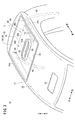
- FIG. 2 is a perspective view illustrating a roof panel of the vehicle in FIG. 1.
- the vehicle 10 includes a roof panel 12, a vehicle air conditioning system 14 provided on the roof panel 12, and a control device (not shown).
- the vehicle air conditioning system 14 includes a roof cover 16 that covers the roof panel 12, a ventilation path 18 formed between the roof panel 12 and the roof cover 16, and through which air can flow, and provided in the ventilation path 18.
- a cooling fan 22 that promotes the flow of air in the ventilation path 18.
- components of the air conditioning unit 20 except for a compressor 23 described later and a cooling fan 22 are not shown.
- illustration of the vehicle air conditioning system 14 is omitted.
- the vehicle 10 is preferably, for example, a small electric vehicle (MEV: Micro Electric Vehicle) or the like, but is not particularly limited to this.
- MEV Micro Electric Vehicle
- the front-back, up-down, left-right directions will be described according to the arrow directions shown in FIG. “Front” is the traveling direction of the vehicle 10 and “rear” is the opposite direction.
- “Left” and “right” are the left and right directions as viewed from the occupant P of the vehicle 10 facing forward.
- the roof panel 12 has a roof panel main body 26 having a mounting hole 24 formed therethrough, and a concave plate 28 mounted in the mounting hole 24.
- an air-conditioning outlet 32 communicating with a front end portion of a later-described duct 30 of the air-conditioning unit 20 is provided in the roof panel body 26 in front of a head PH of an occupant P seated in a driver seat S. It is formed through.
- a mounting hole 24 is provided behind the head PH of the occupant P sitting on the driver's seat S.
- the concave plate 28 is configured by integrally providing a housing portion 34 having an open top and a flange portion 36 provided at an opening edge of the housing portion 34.
- the bottom side of the housing portion 34 is inserted into the mounting hole 24, and a flange portion 36 is laminated on the upper surface of the roof panel main body 26 and on the outer peripheral edge of the mounting hole 24.
- a seal member (not shown) or the like may be interposed between the roof panel main body 26 and the flange portion 36 that are stacked.
- the laminated roof panel body 26 and the flange portion 36 may be bolted and fixed by bolts and nuts (not shown).
- the concave portion 38 in which the housing portion 34 of the concave plate 28 is depressed toward the cabin 40 is formed.
- the recess 38 accommodates a refrigeration cycle device 42 of the vehicle air conditioning system 14 described below.
- the recess 38 has a drainage hole 44 communicating with the outside of the vehicle 10 to allow water to be discharged from the ventilation passage 18, and a water guiding shape portion 46 for guiding water in the ventilation passage 18 to the drainage hole 44 by gravity or the like. Is provided. As shown in FIG. 3, the drain holes 44 are provided at both ends in the left-right direction at the rear of the vehicle 10. In the present embodiment, the drain holes 44 are formed below the left and right side walls 34 a of the housing 34 respectively. The drain hole 44 may be formed to penetrate the bottom 38 a of the recess 38 facing the roof cover 16. A drain tube 48 communicates with the drain hole 44, and the water in the ventilation path 18 flows into the drain tube 48 through the drain hole 44, so that the water can be led out of the vehicle 10. .
- the water guide shape portion 46 is inclined such that the bottom portion 38a of the concave portion 38 approaches the cabin 40 from the center in the left-right direction to the side (see FIG. 2), and the cabin increases from the front to the rear. It is formed by inclining in the direction approaching 40 (see FIG. 1). That is, the water that has flowed into the concave portion 38 is encouraged by the water guide shape portion 46 to flow downward in the vertical direction, in other words, toward both ends in the left-right direction and backward in the front-rear direction.
- the drainage hole 44 is guided to the drainage hole 44.
- the left side of the center line C (see FIG. 3) extending substantially in the center in the left-right direction is also referred to as a left concave portion 46L, and the right side of the center line C.
- One is also referred to as a right concave portion 46R.
- a convex portion 50 that projects upward is provided substantially at the center of the concave portion 38 in the left-right direction.
- an air-conditioning intake 52 is formed in the protruding end surface 50 a of the projection 50 as a communication hole that communicates the rear end of the duct 30 with the cabin 40.
- the roof cover 16 is provided so as to cover the roof panel 12, whereby the ventilation path 18 is formed between the roof cover 16 and the roof panel 12.
- the ventilation path 18 is formed between the roof cover 16 and the roof panel 12.
- an inlet 54 through which the traveling wind of the vehicle 10 can be taken into the ventilation path 18, and at the rear end of the ventilation path 18,
- An outlet 56 for discharging the air flowing through the air outlet 18 is provided. That is, running air and the like can be circulated through the ventilation path 18 from the inlet 54 to the outlet 56.
- the air conditioning unit 20 includes a duct 30 communicating with the cabin 40 of the vehicle 10 via an air conditioning intake 52 and an air conditioning outlet 32 formed through the roof panel 12, and a refrigeration cycle device 42 for cooling air in the duct 30. And a duct fan 58 that takes in the air in the cabin 40 into the duct 30 from the air conditioning intake 52 and blows out the air cooled by the refrigeration cycle device 42 (hereinafter, also referred to as cooling air) from the air conditioning outlet 32 to the cabin 40.
- the air-conditioning outlet 32 may be provided with a wind direction adjusting mechanism (not shown) capable of adjusting the direction in which the cooling air is blown out by using a louver or the like.
- the outer wall surface 30a above the duct 30 and the roof cover 16 are arranged apart from each other, and a space through which air can flow is formed therebetween.
- the duct 30 includes a front portion 60 communicating with the air conditioning outlet 32, a rear portion 62 communicating with the air conditioning intake 52, and a housing disposed between the front portion 60 and the rear portion 62.
- the part 64 is provided integrally.
- the front portion 60 is mainly disposed between the roof cover 16 and a portion of the roof panel body 26 in front of the mounting hole 24.
- the rear part 62 and the accommodation part 64 are disposed in the recess 38.
- the rear part 62 communicates with the air conditioning intake 52 by being connected to the protruding end face 50 a of the convex part 50.
- a duct fan 58 is provided inside the rear portion 62.
- the accommodation portion 64 has a height in the vertical direction that is larger than the front portion 60 and the rear portion 62, and accommodates an evaporator 66 of the refrigeration cycle device 42, which will be described later, inside the accommodation portion 64.
- the refrigeration cycle device 42 is configured by sequentially connecting the compressor 23, the condenser 70, an expansion valve (not shown), and the evaporator 66 via a refrigerant pipe (not shown).
- the compressor 23 is disposed outside the duct 30 in the air passage 18 and beside the duct fan 58 to compress the refrigerant. That is, as shown in FIG. 2, the compressor 23 is disposed to the left or right of the center (center line C) of the recess 38 in the left-right direction. In the present embodiment, the compressor 23 is disposed in the left concave portion 46L on the left side of the center line C of the concave portion 38.
- the compressor 23 may be provided in the right concave portion 46R.
- the compressor 23 is arranged so that its longitudinal direction is inclined with respect to the vertical direction.
- the angle (inclination angle ⁇ ) at which the longitudinal direction of the compressor 23 is inclined with respect to the vertical direction is set to 30 °.
- the inclination angle ⁇ is not limited to 30 °, and may be adjusted within a range of an allowable inclination angle determined according to the specifications of the compressor 23.
- a portion of the bottom 38 a of the concave portion 38 where the compressor 23 is disposed is provided with a housing groove 72 that is further depressed toward the cabin 40. Houses the compressor 23.
- the bottom surface of the storage groove 72 is inclined in a direction to guide water to the drain hole 44.
- the bottom surface of the accommodation groove 72 is, for example, from the center in the left-right direction to the left and from the front to the rear.
- a portion of the roof cover 16 facing the compressor 23 may be provided with an avoiding portion 16 a protruding upward from other portions of the roof cover 16. By providing the avoiding portion 16a, contact between the roof cover 16 and the compressor 23 is avoided.
- the condenser 70 is disposed behind the duct 30 in the air passage 18, and cools the refrigerant compressed by the compressor 23 by exchanging heat with the air in the air passage 18. And liquefy.
- the expansion valve decompresses the liquefied refrigerant and adiabatically expands the refrigerant.
- the evaporator 66 Since the evaporator 66 is disposed in the duct 30 as described above, the evaporator 66 is disposed in the ventilation path 18 ahead of the condenser 70. Further, the evaporator 66 cools the air by exchanging heat between the refrigerant, which has become low in temperature through the expansion valve, and the air in the cabin 40 taken into the duct 30.
- the cooling fan 22 is provided behind the condenser 70 in the ventilation path 18. By driving the cooling fan 22, a negative pressure is applied to the front of the cooling fan 22 in the ventilation path 18. This makes it possible to efficiently take air from the inlet 54 into the ventilation path 18 and circulate the air to the outlet 56.
- control device includes a control unit, an operation panel, and the like.
- the control unit is composed of a well-known microcomputer including a CPU, a ROM, a RAM, and the like, and peripheral circuits.
- a program for air-conditioning control and the like is stored in the ROM, and various calculations and processes are performed based on the program. I do.
- the operation panel is provided, for example, on or near the instrument panel 74 of the vehicle 10 shown in FIG. 1 and has an on / off switch (not shown) for the air conditioning unit 20 and the like.
- an on / off switch for the air conditioning unit 20 and the like.
- the occupant P operates the on / off switch of the air conditioning unit 20, it is possible to switch between starting and stopping the operation of the air conditioning unit 20, in other words, to start and stop supplying the cooling air to the cabin 40. ing.
- the vehicle 10 is basically configured as described above.
- the control unit puts the compressor 23, the duct fan 58, the cooling fan 22, and the like into an operating state.
- the compressor 23 By setting the compressor 23 to the operating state, the refrigerant circulates in the refrigerant pipe of the refrigeration cycle device 42 while changing the state, and the temperature of the evaporator 66 decreases.
- the air in the cabin 40 is taken into the duct 30 by setting the duct fan 58 in the operating state. This air is cooled by the heat exchange with the evaporator 66 whose temperature has decreased as described above, and is then blown out to the cabin 40. By circulating the air between the cabin 40 and the duct 30 in this manner, the cabin 40 is cooled.
- the cooling fan 22 By operating the cooling fan 22, the flow of air from the front to the rear in the ventilation path 18 is promoted. Thereby, the heat dissipation of the refrigerant in the condenser 70 is promoted, so that the cooling efficiency of the air conditioning unit 20 can be improved. Further, the temperature of the compressor 23 and the like can be prevented from rising, and the refrigeration cycle device 42 can be operated satisfactorily.
- the control unit operates the compressor 23, the duct fan 58, and the cooling fan 22. Is stopped. Thereby, the circulation of the refrigerant in the refrigeration cycle device 42 is stopped, and the circulation of the air between the cabin 40 and the duct 30 is stopped, so that the cooling of the cabin 40 is stopped.
- a refrigeration cycle device 42 whose height in the vertical direction tends to be larger among the air conditioning units 20 is provided in the concave portion 38 provided so as to be depressed toward the cabin 40 with respect to the roof panel 12. Will be accommodated. For this reason, even if the vehicle air conditioning system 14 is provided on the roof panel 12, an increase in vehicle height can be suppressed.
- rainwater or the like may enter along with the air.
- dew condensation water may be generated in the ventilation path 18 due to a temperature difference between the outside air temperature and the refrigerant in the refrigerant pipe.
- the recess 38 is provided with a drain hole 44 that communicates with the outside of the vehicle 10 and allows water to be discharged from the ventilation path 18.
- the concave portion 38 depressed toward the cabin 40 is disposed below the roof panel 12 in the vertical direction. For this reason, water in the ventilation path 18 such as rainwater and dew condensation water easily flows toward the recess 38 by gravity.
- the drainage hole 44 By providing the drainage hole 44 in such a concave portion 38, it becomes possible to drain well to the outside of the vehicle 10 through the drainage hole 44. Therefore, even if water enters the ventilation path 18 or water is generated in the ventilation path 18, it is possible to effectively suppress such water from remaining in the ventilation path 18.
- the arrangement and the number of the drain holes 44 are not particularly limited, and may be provided so that the water flowing into the concave portion 38 can be drained.
- the water guide shape portion 46 that is recessed toward the cabin 40 and guides water to the drain hole 44 is provided at the bottom 38 a of the recess 38 facing the roof cover 16. In this case, the water in the ventilation path 18 can be more effectively guided to the drain hole 44 by the water guide shape portion 46 and discharged to the outside of the vehicle 10.
- the water guide shape portion 46 is formed by inclining the bottom portion 38 a in a direction approaching the cabin 40 from the center in the left-right direction of the vehicle 10 toward the side, and the concave portion 38 has Drain holes 44 are provided at both ends in the direction.
- the water guide shape portion 46 is formed by inclining the bottom portion 38 a in a direction approaching the cabin 40 from one (front) to the other (rear) in the front-rear direction of the vehicle 10. 38, a drain hole 44 is provided at the other (rear) end in the front-rear direction.
- the water in the ventilation passage 18 can be effectively guided to the drain hole 44 and discharged to the outside of the vehicle 10 by the water guiding shape portion 46 having a simple configuration.
- the structure of the water guide shape portion 46 is not particularly limited as long as it can guide water to the drain hole 44 by using gravity.
- the water guide shape portion 46 may be a groove (not shown) provided in the bottom portion 38 a so as to communicate with the drain hole 44.
- the water guide shape portion 46 is inclined in a direction approaching the cabin 40 from one end side in the left-right direction to the other end side, and guides water to a drain hole 44 provided in the other end side in the left-right direction. It may be.
- the refrigeration cycle device 42 includes the compressor 23 that compresses the refrigerant, and the compressor 23 is disposed to the left or right of the center of the recess 38 in the left-right direction. .
- the left and right sides of the recess 38 are provided closer to the cabin 40 than the center. For this reason, it is possible to more effectively suppress the increase in the height of the vehicle 10 by arranging the compressor 23 in the refrigerating cycle device 42, the height of which in the vertical direction is likely to be large, in the recess 38. Becomes possible.
- the compressor 23 is arranged so that its longitudinal direction is inclined with respect to the vertical direction of the vehicle 10. As described above, by providing the compressor 23 in the recess 38 in a state where the compressor 23 is tilted within a range permitted according to the specifications and the like, it is possible to more effectively suppress the height of the vehicle 10 from increasing. it can.
- the compressor 23 may be provided along the vertical direction, that is, so that the inclination angle ⁇ is 0 °. Further, if permitted by the specifications of the compressor 23, the compressor 23 may be arranged so that the inclination angle ⁇ is 90 °, in other words, the longitudinal direction of the compressor 23 is along the front-rear direction or the left-right direction.
- a portion of the bottom portion 38a where the compressor 23 is disposed is provided with an accommodation groove 72 that is further depressed toward the cabin 40, and the accommodation groove 72 accommodates the compressor 23. did. This makes it possible to more effectively suppress the height of the vehicle 10 from increasing.
- the recess 38 may not be provided with the accommodation groove 72.
- the bottom surface of the accommodation groove 72 is inclined in a direction to guide water to the drain hole 44. Therefore, even if the accommodation groove 72 is provided to reduce the vehicle height as described above, it is possible to suppress the accumulation of water inside the accommodation groove 72. Further, by providing the roof cover 16 with the avoidance portion 16a as in the above-described embodiment, it is also possible to effectively reduce the vehicle height of the portion other than the avoidance portion 16a.
- a communication hole (air-conditioning intake port 52) for communicating one end (rear end) of the duct 30 with the cabin 40 is provided substantially at the center of the recess 38 in the left-right direction.
- the approximate center of the recess 38 in the left-right direction is located above both ends. For this reason, by providing a communication hole at substantially the center in the left-right direction of the concave portion 38, it is easy to prevent water in the ventilation path 18 from entering the duct 30 or the cabin 40 through the air-conditioning intake 52. Become.
- the air conditioning outlet 32 is provided in front of the roof panel 12 and the air conditioning intake 52 is provided in the rear, but the invention is not particularly limited to this.
- the air-conditioning intake port 52 may be provided in front of the roof panel 12 and the air-conditioning air outlet 32 may be provided behind. In this case, the communication hole becomes the air conditioning outlet 32.
- the concave portion 38 is arranged behind the occupant P seated in the driver's seat S behind. In this case, it is easy to secure a space above the occupant P in the driver's seat S. It should be noted that the arrangement of the concave portion 38 in the roof panel 12 is not particularly limited, and the concave portion 38 may be disposed at any position of the roof panel 12.
- the roof panel 12 has the roof panel main body 26 provided with the mounting holes 24 and the concave plate 28 which is mounted in the mounting holes 24 to form the concave portions 38.
- the roof panel 12 may be integrally formed from one member.
- the present invention is not particularly limited to the above-described embodiment, and various modifications can be made without departing from the gist of the present invention.
Landscapes
- Physics & Mathematics (AREA)
- Thermal Sciences (AREA)
- Engineering & Computer Science (AREA)
- Mechanical Engineering (AREA)
- Air-Conditioning For Vehicles (AREA)
Abstract
L'invention concerne un véhicule (10) comprenant un panneau de toit (12) et un système de climatisation de véhicule (14) disposé dans le panneau de toit (12). Le système de climatisation de véhicule (14) comprend : un couvercle de toit (16) qui recouvre le panneau de toit (12) ; un passage d'air (18) formé entre le panneau de toit (12) et le couvercle de toit (16) et à travers lequel de l'air peut s'écouler ; et une unité de climatisation (20) disposée dans le passage d'air (18). L'unité de climatisation (20) comprend : un conduit (30) relié à un habitacle (40) ; et un dispositif à cycle de refroidissement (42) qui refroidit l'air amené dans le conduit (30) depuis l'habitacle (40). Une section évidée (38) qui s'enfonce vers l'habitacle (40) est disposée dans le panneau de toit (12) et le dispositif à cycle de refroidissement (42) est logé dans la section évidée (38).
Applications Claiming Priority (2)
| Application Number | Priority Date | Filing Date | Title |
|---|---|---|---|
| JP2018-162341 | 2018-08-31 | ||
| JP2018162341 | 2018-08-31 |
Publications (1)
| Publication Number | Publication Date |
|---|---|
| WO2020044901A1 true WO2020044901A1 (fr) | 2020-03-05 |
Family
ID=69645245
Family Applications (1)
| Application Number | Title | Priority Date | Filing Date |
|---|---|---|---|
| PCT/JP2019/029455 Ceased WO2020044901A1 (fr) | 2018-08-31 | 2019-07-26 | Véhicule |
Country Status (1)
| Country | Link |
|---|---|
| WO (1) | WO2020044901A1 (fr) |
Citations (5)
| Publication number | Priority date | Publication date | Assignee | Title |
|---|---|---|---|---|
| JPS58206417A (ja) * | 1982-05-24 | 1983-12-01 | Mitsubishi Electric Corp | 車両用空気調和装置 |
| US4641502A (en) * | 1985-01-09 | 1987-02-10 | The Duo-Therm Corporation | Roof mount air conditioner |
| JPH08183326A (ja) * | 1994-11-02 | 1996-07-16 | Nippondenso Co Ltd | 車両用空気調和装置 |
| JP2000343931A (ja) * | 1999-06-02 | 2000-12-12 | Bosch Automotive Systems Corp | 車両用空調ユニット |
| JP2004262409A (ja) * | 2003-03-04 | 2004-09-24 | Denso Corp | 車載用空調装置 |
-
2019
- 2019-07-26 WO PCT/JP2019/029455 patent/WO2020044901A1/fr not_active Ceased
Patent Citations (5)
| Publication number | Priority date | Publication date | Assignee | Title |
|---|---|---|---|---|
| JPS58206417A (ja) * | 1982-05-24 | 1983-12-01 | Mitsubishi Electric Corp | 車両用空気調和装置 |
| US4641502A (en) * | 1985-01-09 | 1987-02-10 | The Duo-Therm Corporation | Roof mount air conditioner |
| JPH08183326A (ja) * | 1994-11-02 | 1996-07-16 | Nippondenso Co Ltd | 車両用空気調和装置 |
| JP2000343931A (ja) * | 1999-06-02 | 2000-12-12 | Bosch Automotive Systems Corp | 車両用空調ユニット |
| JP2004262409A (ja) * | 2003-03-04 | 2004-09-24 | Denso Corp | 車載用空調装置 |
Similar Documents
| Publication | Publication Date | Title |
|---|---|---|
| JP6592466B2 (ja) | 車両用空調システム | |
| US11511651B2 (en) | Vehicular air conditioner | |
| CN104995047B (zh) | 车辆用空调装置 | |
| US9016069B2 (en) | Condensate water removing apparatus for vehicle air conditioners | |
| JP5314462B2 (ja) | 車両用外気導入装置 | |
| CN109823137B (zh) | 客车空调 | |
| US11618301B2 (en) | Vehicle air conditioner | |
| US20160325603A1 (en) | Air conditioning device for vehicle | |
| US10538143B2 (en) | Air-conditioning apparatus for vehicle | |
| WO2020044901A1 (fr) | Véhicule | |
| US6942564B1 (en) | Passenger foot duct | |
| WO2018150783A1 (fr) | Dispositif de climatisation pour véhicules | |
| CN107953740B (zh) | 空调单元 | |
| KR20170118998A (ko) | 차량용 루프형 공조장치 | |
| KR20160091227A (ko) | 냉난방 모듈 | |
| KR100284146B1 (ko) | 레크레이션어블 비이클용 공기 조화기의 스크롤하우징 | |
| JP6065817B2 (ja) | 車室内温度検出モジュール及びこれを備えた車両用空調装置 | |
| JP2020032913A (ja) | 車両空調システム及びその制御方法 | |
| KR101746232B1 (ko) | 차량용 공기조화장치 | |
| KR101605915B1 (ko) | 전기자동차의 냉난방장치 | |
| JP2010195367A (ja) | 温度調節装置 | |
| JP2017140911A (ja) | 車両用空調装置 | |
| KR102575996B1 (ko) | 차량용 공조장치 | |
| WO2020044902A1 (fr) | Véhicule | |
| JP2010127507A (ja) | 冷凍車 |
Legal Events
| Date | Code | Title | Description |
|---|---|---|---|
| 121 | Ep: the epo has been informed by wipo that ep was designated in this application |
Ref document number: 19854203 Country of ref document: EP Kind code of ref document: A1 |
|
| NENP | Non-entry into the national phase |
Ref country code: DE |
|
| 122 | Ep: pct application non-entry in european phase |
Ref document number: 19854203 Country of ref document: EP Kind code of ref document: A1 |
|
| NENP | Non-entry into the national phase |
Ref country code: JP |