WO2020045346A1 - 走行車両 - Google Patents
走行車両 Download PDFInfo
- Publication number
- WO2020045346A1 WO2020045346A1 PCT/JP2019/033319 JP2019033319W WO2020045346A1 WO 2020045346 A1 WO2020045346 A1 WO 2020045346A1 JP 2019033319 W JP2019033319 W JP 2019033319W WO 2020045346 A1 WO2020045346 A1 WO 2020045346A1
- Authority
- WO
- WIPO (PCT)
- Prior art keywords
- tilt
- lock
- unit
- steering shaft
- lock unit
- Prior art date
- Legal status (The legal status is an assumption and is not a legal conclusion. Google has not performed a legal analysis and makes no representation as to the accuracy of the status listed.)
- Ceased
Links
Images








Classifications
-
- B—PERFORMING OPERATIONS; TRANSPORTING
- B62—LAND VEHICLES FOR TRAVELLING OTHERWISE THAN ON RAILS
- B62D—MOTOR VEHICLES; TRAILERS
- B62D1/00—Steering controls, i.e. means for initiating a change of direction of the vehicle
- B62D1/02—Steering controls, i.e. means for initiating a change of direction of the vehicle vehicle-mounted
- B62D1/16—Steering columns
- B62D1/18—Steering columns yieldable or adjustable, e.g. tiltable
- B62D1/184—Mechanisms for locking columns at selected positions
-
- B—PERFORMING OPERATIONS; TRANSPORTING
- B62—LAND VEHICLES FOR TRAVELLING OTHERWISE THAN ON RAILS
- B62D—MOTOR VEHICLES; TRAILERS
- B62D1/00—Steering controls, i.e. means for initiating a change of direction of the vehicle
- B62D1/02—Steering controls, i.e. means for initiating a change of direction of the vehicle vehicle-mounted
- B62D1/16—Steering columns
- B62D1/18—Steering columns yieldable or adjustable, e.g. tiltable
- B62D1/187—Steering columns yieldable or adjustable, e.g. tiltable with tilt adjustment; with tilt and axial adjustment
Definitions
- the present invention relates to a traveling vehicle such as a tractor.
- a traveling vehicle disclosed in Patent Document 1 has a steering shaft to which a steering handle is attached.
- the steering shaft is capable of adjusting the tilt angle and the length.
- the traveling vehicle has a tilt lock portion that locks the steering shaft at the adjusted tilt angle and a telescopic lock portion that locks the steering shaft at the adjusted length.
- unlocking of the steering shaft by the tilt lock unit and unlocking of the steering shaft by the telescopic lock unit are performed by different levers. That is, the adjustment of the tilt angle and the length of the steering shaft have to be performed by separate operations. Therefore, there has been a problem that operability when adjusting the tilt angle and the length of the steering shaft is poor.
- a traveling vehicle is a steering shaft to which a steering handle is attached, the steering shaft being capable of adjusting a tilt angle and being adjustable in length, and a tilt angle adjusting the steering shaft.
- An operation having a tilt lock portion that locks the steering shaft, a telescopic lock portion that locks the steering shaft to the adjusted length, and an operation area that releases both lock by the tilt lock portion and release of lock by the telescopic lock portion. And a member.
- the operation member is a first position which is a position before the operation and a position operated from the first position.
- the operation member releases the lock by the tilt lock portion and releases the lock by the telescopic lock portion.
- a third position which is a position operated from the second position and unlocked by the tilt lock unit and the telescopic lock unit.
- the operation member further includes an interlocking mechanism that interlocks the tilt lock unit and the telescopic lock unit.
- the interlocking mechanism includes a first interlocking unit that interlocks the operation member with the tilt lock unit, (1) a second interlocking unit that interlocks the interlocking unit and the telescopic lock unit, and a play unit that does not interlock the first interlocking unit and the telescopic lock unit until a predetermined amount is operated from a position before the operation member is operated.
- the first interlocking unit has a release arm that unlocks the tilt lock unit in conjunction with the operation of the operation member, and the second interlocking unit interlocks with the operation of the operation member.
- the one end portion of the second relay link is provided in the relay arm and is formed by a long groove through which the one end portion is inserted, and the one end portion relatively moves within the long groove until the operation member is operated by the predetermined amount.
- the relay arm and the operating member are not interlocked with each other, and after operating the operating member by the predetermined amount, by further operating, the end of the long groove is moved to the one end side portion. Interlocking with said actuating member and the relay arm in contact.
- a tilt shaft that is the center of the tilting operation of the steering shaft is provided, and in a state where the tilt angle of the steering shaft can be adjusted and the length can be adjusted, one end side portion of the second relay link is provided. Coincides with the axis of the tilt axis.
- both the release of the lock by the tilt lock portion and the release of the lock by the telescopic lock portion can be performed by the operation member.
- the operability of adjusting the length of the steering shaft and adjusting the tilt angle can be improved.
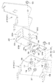
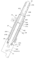
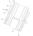
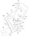
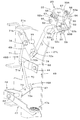
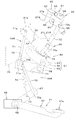
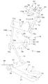
- FIG. 3 is an exploded perspective view of the cockpit. It is a side sectional view of a lower part of a steering shaft. It is an expanded sectional view showing the state where the steering shaft was locked to the adjusted length. It is an expanded sectional view showing the state where the lock of the longitudinal direction of the steering shaft was released. It is a side view of a lock part which shows the state where the steering shaft was locked to the adjusted tilt angle. It is a side view showing the state where the lock of the tilt angle of the steering shaft was released. It is a perspective view of an interlocking mechanism.
- FIG. 5 is a side view of the interlocking mechanism when the operation pedal is operated to a second position. It is a side view of an interlocking mechanism when an operation pedal is further operated from a 2nd position.
- FIG. 8 is a side view of the interlocking mechanism when the operation pedal is operated to a third position. It is a side view of a running vehicle.
- FIG. 17 is a schematic side view showing the traveling vehicle according to the present embodiment.
- the tractor 1 is illustrated as a traveling vehicle.
- the direction of arrow A1 in FIG. 17 (the forward direction of the tractor 1) will be described as forward
- the direction of arrow A2 in FIG. 17 (the backward direction of the tractor 1) will be described as backward. Therefore, the near side in FIG. 17 is the left side, and the far side in FIG. 17 is the right side.
- a horizontal direction orthogonal to the front-rear direction A3 will be described as a vehicle width direction.
- the direction from the center of the tractor 1 in the vehicle width direction to the right or left will be described as the vehicle outward (also referred to as the vehicle width direction outward).
- the outside of the vehicle is a direction that is away from the center of the tractor 1 in the vehicle width direction.
- the direction opposite to the outside of the vehicle will be described as the inside of the vehicle (also referred to as the inside of the vehicle width direction).
- the inside of the vehicle is a direction that is closer to the center of the tractor 1 in the vehicle width direction.
- the tractor 1 has a vehicle body 2 that can travel.
- the vehicle body 2 includes a prime mover E1, a flywheel housing 3, a clutch housing 4, a transmission case 5, and a front axle frame 6.
- the prime mover E1 is a diesel engine.
- the prime mover E ⁇ b> 1 is located at the front of the tractor 1 and is covered by a hood 10.
- the prime mover E1 may be an electric motor or a hybrid type having a diesel engine and an electric motor.
- the flywheel housing 3 is connected to the rear of the prime mover E1 and houses the flywheel.
- the clutch housing 4 is connected to a rear portion of the flywheel housing 3 and houses a clutch that transmits the power of the prime mover E1 transmitted via the flywheel in an intermittent manner.
- the transmission case 5 is connected to a rear portion of the clutch housing 4 and houses a transmission (transmission) that changes the power transmitted through the clutch.
- the transmission has a forward / reverse switching mechanism for switching the power transmitted by the transmission forward or reverse to switch to forward or reverse output.
- the front axle frame 6 is fixed to the prime mover E1 and protrudes forward from the prime mover E1.
- the front axle frame 6 supports a front axle case 15.
- the tractor 1 has a traveling device 8 that supports the vehicle body 2 so as to be able to travel.
- the traveling device 8 is a wheel-type traveling device having a plurality of front wheels 11L and 11R provided at a front portion of the vehicle body 2 and a plurality of rear wheels 12L and 12R provided at a rear portion of the vehicle body 2.
- the plurality of front wheels include a left front wheel 11L supported on the left side of the front axle case 15 and a right front wheel 11R supported on the right side of the front axle case 15.
- the plurality of rear wheels include a left rear wheel 12L supported on the left side of the transmission case 5 and a right rear wheel 12R supported on the right side of the transmission case 5.
- the traveling device 8 may be a semi-crawler traveling device (a traveling device having a front wheel and a crawler traveling mechanism employed in place of the rear wheel).
- the left front wheel 11L and the right front wheel 11R are steered wheels that can be steered by movement of a cylinder rod of a steering cylinder 16 provided in a front portion of the front axle case 15.
- the steering cylinder 16 is constituted by a hydraulic cylinder.
- the steering device that steers the vehicle body 2 may be a hydraulic power steering device including the steering cylinder 16 described above, or may steer the front wheels 11L and 11R using the power of an electric motor. It may be an electric power steering device or a steering device that transmits the operating force of the steering handle 19 to the front wheels 11L and 11R by a mechanical power transmission mechanism.
- a driver's seat 13 on which a driver (operator) sits is mounted on a rear portion of the vehicle body 2.
- a steering device 14 that steers the vehicle body 2 is provided in front of the driver's seat 13.
- the steering device 14 is provided on a back surface of a support member 30 erected on the vehicle body 2.
- the support member 30 is disposed at the rear of the bonnet 10 and separates the inside of the bonnet 10 from a region where the driver's seat 13 and the control device 14 are disposed.
- the steering device 14 includes a steering handle 19 that steers the vehicle body 2 (the front wheels 11L and 11R), a support frame 17 that supports the steering handle 19, and a steering cover 18 that covers the steering platform.
- the support frame 17 includes a fixed bracket 21 fixed to the back surface of the support member 30 and a fixed bracket 21 around an axis (tilt axis) X1 extending in the vehicle width direction.
- a movable bracket 22 supported rotatably (tilted).
- the fixed bracket 21 includes a first bracket 21L and a second bracket 21R.
- the first bracket 21L and the second bracket 21R are formed of a plate material, and are arranged at intervals in the vehicle width direction.
- the first bracket 21 ⁇ / b> L is formed to be long in the up-down direction, and is fixed to the back surface of the support member 30 and the lower end is fixed to the lower portion of the support member 30.
- the second bracket 21R is arranged on the upper right side of the first bracket 21L.
- the second bracket 21R is fixed to the back surface of the support member 30.
- the movable bracket 22 is formed of a plate material, and has an upper wall 22A, a first side wall 22B fixed to a left end of the upper wall 22A, and a lower part from a right end of the upper wall 22A. And a second side wall 22C extending to the side.
- a circular opening 23 is formed in the upper wall 22A.
- the opening 23 is formed through the upper wall 22A.
- the movable bracket 22 is provided with a steering post 27.
- the steering post 27 supports a steering shaft 26.
- the steering handle 19 is attached to the upper part of the steering shaft 26 (see FIG. 17).
- the steering post 27 has an outer cylinder 27A, an inner cylinder 27B, and a support cylinder 27C.
- the lower end of the outer cylinder 27A is fixed to the upper wall 22A.
- the outer cylinder 27A is provided so as to surround the opening 23.
- the inner cylinder 27B is inserted into the outer cylinder 27A.
- the inner cylinder 27B is movable in the axial direction with respect to the outer cylinder 27A, and is not rotatable around the axis by key connection or the like.
- a ring disk-shaped end plate 27D is fixed to the upper end of the inner cylinder 27B.
- the lower end of the support cylinder 27C is fixed to the end plate 27D.
- a support bush 27E is inserted into the upper part of the support cylinder 27C.
- the steering shaft 26 has a first shaft 28 and a second shaft 29.
- the first shaft 28 is disposed in the inner cylinder 27B and has a lower portion protruding below the upper wall 22A through the opening 23.
- a lower portion of the first shaft 28 is supported by a bearing member 31 fixed to the upper wall portion 22A so as to be rotatable around the axis.
- the bearing member 31 has an upper portion fixed to the inner peripheral surface of the opening 23 and protrudes downward from the upper wall portion 22A.
- the lower portion of the first shaft 29 protrudes downward from the bearing member 31, and a steering valve is connected to this protruding portion via a coupling, for example.
- the steering valve is a rotary valve that is operated by the steering shaft 26 and outputs hydraulic oil for operating the steering cylinder 16. Note that the steering valve does not have to be directly connected to the first shaft 29.
- the steering valve may be arranged below the steering device 14, and the first shaft 29 and the steering valve may be linked to each other by a power transmission mechanism having a universal joint.
- the second shaft 29 has a lower large-diameter portion 29A and an upper small-diameter portion 29B.
- the large diameter portion 29A is arranged in the inner cylinder 27B, and is spline-coupled to the first shaft 28. Therefore, the second shaft 29 is movable in the axial direction with respect to the first shaft 28 and is integrally rotatable around the axial center. That is, the steering shaft 26 can be extended and contracted in the axial direction, and the length can be adjusted by extending and contracting the steering shaft 26.
- the upper end of the large diameter portion 29A is in contact with the end plate 27D.
- the small diameter portion 29B protrudes upward from the end plate 27D and passes through the support bush 27E.
- the small diameter portion 29B is supported by the support bush 27E so as to be rotatable around the axis.
- the steering handle 19 is mounted above the small diameter portion 29B.
- the tractor 1 has a telescopic lock section 20 for locking the steering shaft 26 to the adjusted length.
- the telescopic lock unit 20 has a lock member (referred to as a first lock member) 33 that restricts expansion and contraction of the steering shaft 26.
- the first lock member 33 is provided above the outer cylinder 27A.
- the first lock member 33 is formed in a tubular shape, and is fitted to the outside of the inner cylinder 27B so as to be relatively movable (movable up and down) in the axial direction.
- the upper part 33A of the first lock member 33 is formed in a cylindrical shape.
- the first lock member 33 has a tapered portion 33B at a lower portion.
- the tapered portion 33B is formed on a tapered surface whose diameter gradually decreases (the diameter gradually decreases) as the outer surface shape goes downward, and is formed in a conical outer shape.
- the telescopic lock portion 20 has an insertion portion 27a with which the tapered portion 33B of the first lock member 33 engages.
- the insertion portion 27a is formed on an upper portion of the outer cylinder 27A.
- the insertion portion 27a is formed in a tapered surface whose diameter gradually increases (the diameter gradually increases) as the inner surface shape moves upward.
- FIG. 6 shows a state where the first lock member 33 is located at the lock position. In this state, the tapered portion 33B of the first lock member 33 is pushed between the insertion portion 27a and the inner cylinder 27B. Therefore, in the lock position, the first lock member 33 restricts the relative movement between the outer cylinder 27A and the inner cylinder 27B by the wedge action. Thereby, the steering shaft 26 can be locked at the adjusted length.
- FIG. 7 shows the highest position where the first lock member 33 is moved to the uppermost position from the lock position.
- the first lock member 33 is displaced upward from the lock position with respect to the insertion portion 27a and the inner cylinder 27B. Therefore, at the highest position, a gap is formed between the insertion portion 27a and the tapered portion 33B, the wedge action is released, and the relative movement between the outer cylinder 27A and the inner cylinder 27B is allowed. Accordingly, the steering shaft 26 can be extended and contracted, and the length of the steering shaft 26 can be adjusted.
- the first side wall 22B is pivotally supported by the first bracket 21L via a first tilt shaft (tilt shaft) 25L. More specifically, a vertically intermediate portion of the first side wall portion 22B is rotatably supported around the axis (tilt axis X1) of the first tilt shaft 25L on the rear side of the upper portion of the first bracket 21L. .
- the second side wall 22C is pivotally supported by the first bracket 21L via a second tilt shaft (tilt shaft) 25R. Specifically, the second tilt shaft 25R passes through the lower part of the second side wall 22C and the rear part of the lower part of the second bracket 21R.
- the second tilt shaft 25R is prevented from coming off by screwing the nut 66 (fitting the screws).
- the lower portion of the second bracket 21R is supported by the second bracket 21R so as to be rotatable around the axis (tilt axis X1) of the second tilt shaft 25R.
- the movable bracket 22 is rotatably supported on the fixed bracket 21 around the tilt axis X1 by the first tilt shaft 25L and the second tilt shaft 25R.
- the steering shaft 26 can be tilted (tilted) around the tilt axis X1.
- the first tilt axis 25L and the second tilt axis 25R (tilt axis) are the centers of the tilt operation (tilt operation) of the steering shaft 26, and the steering shaft 26 adjusts the tilt angle about the tilt axis X1 (tilt adjustment). ) Is possible.
- a support plate 34 is provided inside (the right side) of the first side wall 22 ⁇ / b> B.
- the first tilt shaft 21L is fixed to an upper portion of the support plate 34.
- the first tilt shaft 21L penetrates the first side wall 22B and the first bracket 21L.
- the first tilt shaft 21L is prevented from being pulled out by screwing the nut 35 into place.
- a support shaft 36 is fixed to an intermediate portion in the vertical direction of the support plate 34 and to the front portion.
- the support shaft 36 is inserted through the first bracket 21L.
- the support shaft 36 is prevented from being pulled out by screwing a nut 37.
- the support plate 34 is fixedly attached to the first bracket 21L by a first tilt shaft 21L and a nut 35 and a support shaft 36 and a nut 37.
- the tractor 1 has a tilt lock portion 61 that locks the steering shaft 26 at the adjusted tilt angle.
- the tilt lock portion 61 includes the first meshing portion 24, a lock member (referred to as a second lock member) 40, and a locking member 43.
- the first engagement portion 24 is formed at the lower end of the first side wall 22B.
- the first engagement portion 24 has a plurality of engagement teeth 24a.
- the plurality of engaging teeth 24a are formed in an arc direction centered on the tilt axis X1.
- a restriction hole 38 is formed between the first tilt shaft 21L and the first meshing portion 24 in the first side wall 22B.
- the restriction hole 38 is formed to penetrate the first side wall portion 22B, and is formed as a circular arc-shaped hole centered on the tilt axis X1.
- a regulating pin 39 is inserted through the regulating hole 38.
- the restriction pin 39 is fixed to the support plate 34. Therefore, the movable bracket 22 can be tilted within a range in which the regulation pin 39 relatively moves from one end to the other end in the regulation hole 38.
- the second lock member 40 is disposed below the first side wall 22B. As shown in FIGS. 3 and 4, the second lock member 40 is disposed between the first bracket 21L and the support plate 34. Further, the second lock member 40 is supported by the support shaft 36 so that the front portion can rotate about an axis extending in the vehicle width direction.
- a second meshing portion 41 having a plurality of engagement teeth 41a is formed.
- the second meshing section 41 can mesh with the first meshing section 24.
- the plurality of engagement teeth 41a are formed in an arc direction centered on the tilt axis X1 in a state where the second meshing portion 41 is meshed with the first meshing portion 24.
- the engagement of the engagement teeth 24a of the first engagement portion 24 with the engagement teeth 41a of the second engagement portion 41 restricts the swing of the movable bracket 22 and locks the steering shaft 26 at the adjusted tilt angle. it can.
- the second lock member 40 swings downward, and the second meshing portion 41 separates from the first meshing portion 24, whereby swinging of the movable bracket 22 is allowed, and The tilt angle of the shaft 26 can be adjusted.
- an engagement groove 42 that opens downward is formed in a lower rear portion of the second lock member 40.
- the locking member 43 is disposed below a rear portion of the second lock member 40.
- the locking member 43 is disposed between the first bracket 21L and the support plate 34, and is supported by a pivot 44 having an axis extending in the vehicle width direction at an intermediate portion. .
- the pivot 44 is fixed to a release arm 68 described later, and passes through the first bracket 21L, the locking member 43, and the first side wall 22B.
- the pivot shaft 44 is prevented from being pulled out by screwing a nut 45.
- the pivot 44 is rotatable with respect to the first bracket 21L and the first side wall 22B.
- the locking member 43 is fitted to the pivot 44 so as to be integrally rotatable. Therefore, the locking member 43 and the release arm 68 rotate integrally with the pivot 44.
- the locking member 43 has an engaging portion 43a provided on the upper side and a spring hooking portion 43b provided on the lower side.
- the engaging portion 43a can engage with the engaging groove 42.
- One end of a spring member 46 composed of a tension coil spring is hooked on the spring hook 43b.
- the other end of the spring member 46 is hooked on a spring hook 34 a provided at the front of the support plate 34.
- the spring member 46 urges the locking member 43 in a direction to swing the engaging portion 43a backward.
- FIG. 8 shows a tilt lock state in which the second meshing portion 41 is meshed with the first meshing portion 24.
- the engaging portion 43a is engaged with the lower rear surface of the engaging groove 42.
- the release arm 68 swings downward from this state, the locking member 43 swings against the urging force of the spring member 46 so that the engaging portion 43a moves forward as shown in FIG. I do.
- the engagement portion 43a is disengaged from the lower portion of the rear surface of the engagement groove 42 and moves toward the depth of the engagement groove 42.
- the second lock member 40 swings downward, the second meshing portion 41 is disengaged from the first meshing portion 24, and the tilt angle of the steering shaft 26 can be adjusted.
- an operation pedal (operation member) 47 is provided on the side of the first bracket 21L. Specifically, the operation pedal 47 is disposed on the back surface of the support member 30 and on the side (left side) below the first bracket 21L.
- the operation pedal 47 is interlocked with the tilt lock unit 61 and the telescopic lock unit 20 by the interlocking mechanism 49, and performs an unlocking operation by the tilt lock unit 61 and the telescopic lock unit 20. . That is, the unlocking operation by the tilt lock unit 61 and the telescopic lock unit 20 can be performed by the single operation pedal 47.
- the operation pedal 47 is supported by a bracket member (referred to as a pedal bracket) 48.
- the pedal bracket 48 is arranged on the lower left side of the first bracket 21L, and is fixed to the back surface of the support member 30.
- a rotary shaft 62 having an axis extending in the vehicle width direction is provided on the pedal bracket 48 so as to be rotatable around the axis.
- the front portion of the operation pedal 47 is fixed to the rotation shaft 62 so as to be integrally rotatable.
- the operation pedal 47 has a step portion 47a at the rear portion for the operator to step on.
- the interlocking mechanism 49 includes a first interlocking section 49A for interlocking the operation member 47 and the tilt lock section 61, and a second interlocking section for interlocking the first interlocking section 49A and the telescopic lock section 20. 49B.
- the first interlocking section 49A has an interlocking arm 67, an interlocking link 70, and a release arm 68.
- the interlocking arm 67 has one end (front portion) connected to the rotation shaft 62, and is supported by the pedal bracket 48 via the rotation shaft 62 so as to be vertically swingable. I have. Therefore, the interlocking arm 67 swings up and down integrally with the operation pedal 47.
- a hook hole 73 is formed in the middle of the interlocking arm 67.
- One end of a return spring 74 constituted by a tension coil spring is hooked in the hook hole 73.
- the other end of the return spring 74 is hooked on a bracket member 75 fixed to the back surface of the support member 30.
- a hook hole 76 is formed in the lower portion of the bracket member 75, and the other end of the return spring 74 is hooked in the hook hole 76. The urging force of the return spring 74 urges the interlock arm 67 and the operation pedal 47 to swing upward.
- the interlocking link 70 is formed of a cylindrical bar, and one end (lower end) 70 a is connected to the other end (rear) of the interlock arm 67.
- the one end side portion 70a has an axis extending in the vehicle width direction, and is connected to the interlocking link 70 so as to be rotatable around the axis.
- the other end portion (upper end portion) 70 b of the interlocking link 70 is connected to one end side (front portion) of the release arm 68. More specifically, the other end portion 70b has an axis extending in the vehicle width direction, and is rotatably connected to the release arm 68 about the axis.
- the release arm 68 is disposed above the interlocking arm 67, and the other end (rear part) is pivotally supported by the first bracket 21L via the pivot shaft 44.
- the release arm 68 is pulled down via the interlocking arm 67 and the interlocking link 70 and swings downward.
- the locking member 43 swings in conjunction with the downward swing of the release arm 68, whereby the second meshing portion 41 separates from the first meshing portion 24, and the lock by the tilt lock portion 20 is released. Is done. Therefore, the release arm 68 releases the lock by the tilt lock unit 20 in conjunction with the operation of the operation pedal 47.
- the second interlocking section 49B includes a first relay link 71, a relay arm 69, a second relay link 72, and an operating member 51.
- the relay arm 69 is linked to the release arm 68 by a first relay link 71 and is linked to the operating member 51 by a second relay link.
- the first relay link 71 is formed of a cylindrical bar, and one end portion (lower end portion) 71 a is connected to the release arm 68.
- the one end portion 71 a has an axis extending in the vehicle width direction, and is connected to a front portion of the release arm 68 so as to be rotatable around the axis.
- the one end portion 71a of the first relay link 71 is located forward of the other end portion 70b of the interlocking link 70.
- the other end portion (upper end portion) 71 b of the first relay link 71 is connected to one end side (front portion) of the relay arm 69. More specifically, the other end portion 71b has an axis extending in the vehicle width direction, and is rotatably connected to the relay arm 69 around the axis.
- the relay arm 69 is located above the release arm 68, and the intermediate part is pivotally supported by the first bracket 21L.
- a support cylinder 77 is fixed to an upper portion of the first bracket 21L, and a relay arm 69 is attached to the support cylinder 77 via an attachment member 78.
- the attachment member 78 has an axis X4 extending in the vehicle width direction, and the relay arm 69 is rotatably supported around the axis of the attachment member 78.
- a play groove (play part) 79 is formed on the other end side (rear part) of the relay arm 69.
- the play groove 79 is formed in an arc-shaped long groove that is long in the vertical direction and is centered on the axis X4 of the mounting member 78.
- the second relay link 72 is formed of a cylindrical bar, and has one end portion (lower end portion) 72 a inserted into the play groove 79.
- the one end side portion 72a has an axis extending in the vehicle width direction, and is rotatable around the axis in the play groove 79, and is movable between one end and the other end in the groove longitudinal direction. It has been inserted.
- the other end portion (upper end portion) 72 b of the second relay link 72 is connected to the operating member 51. More specifically, the other end portion 72b has an axis extending in the vehicle width direction, and is connected to the operating member 51 so as to be rotatable around the axis.
- the operating member 51 supports the first lock member 33 movably up and down.
- the operating member 51 is interlocked with the operation pedal 47 via the first interlocking section 49A, the first relay link 71, the relay arm 69, and the second relay link 72, and is interlocked with the operation of the operation pedal 47.
- the lock by the telescopic lock unit 20 is released.
- the operating member 51 has a first member 52 and a second member 53.
- the first member 52 includes a first portion 52a located to the left of the first lock member 33, a second portion 52b extending rearward and downward from a lower rear end of the first portion 52a, and a rear portion of the second portion 52b. And a third portion 52c extending rightward.
- the first portion 52a has a guide groove 54 at an upper portion and a boss 55 at a lower portion.
- a roller 56 is fitted in the guide groove 54 so as to be rotatable around an axis extending in the vehicle width direction and to be movable in the groove longitudinal direction.
- a pin 57 fixed to the upper portion 33 ⁇ / b> A of the first lock member 33 is inserted through the roller 56.
- the boss 55 is located below the front part of the guide groove 54.
- An insertion hole 58 is formed in the second portion 52b. The other end 72b of the second relay link 72 is inserted into the insertion hole 58.
- the second member 53 includes a first portion 53a located to the right of the first lock member 33 and a second portion 53b extending rearward and downward from a lower rear end of the first portion 53a. And a third portion 53c extending leftward from the rear end of the second portion 53b.
- the first portion 53a has a guide groove 54 at an upper portion and a boss 55 at a lower portion.
- a roller 56 is fitted in the guide groove 54 so as to be rotatable around an axis extending in the vehicle width direction and to be movable in the groove longitudinal direction.
- a pin 57 fixed to the upper part 33 ⁇ / b> A of the first lock member 33 is inserted through the roller 56 so as to be relatively rotatable.
- the boss 55 is located below the front part of the guide groove 54.
- the third portion 52c and the third portion 53c are connected by a fastener 59 having a bolt and a nut.
- the boss 55 is attached to an upper portion of the outer cylinder 27A by an attachment member 60.
- the mounting member 60 has an axis X2 extending in the vehicle width direction, and the operating member 51 is supported by the outer cylinder 27A so as to be vertically swingable around the axis X2 of the mounting member 60.
- the guide groove 54 has a lock portion 54a and a lock release portion 54b.
- the lock portion 54a is formed in an arc shape having a radius R1 about the axis X2 of the mounting member 60
- the lock release portion 54b is formed in an arc shape having a radius R2 about the arc center X3 different from the axis X2. Is formed.
- the arc center X3 is a line extending in the vehicle width direction, and is located behind and below the axis X2.
- FIG. 13 shows a state where the first lock member 33 is located at the lock position.
- the roller 56 is located at the lock portion 54a of the guide groove 54.
- the operating member 51 swings upward around the axis X2 to move the roller 56 at the lower end of the unlocking portion 54b. Push up.
- the first lock member 33 is moved upward.
- the rear portion of the operating member 51 is pushed up, the first lock member 33 moves upward until the roller 56 reaches the rear end of the guide groove 54, as shown in the right end diagram in FIG. Is located at the highest position. While the first lock member 33 is displaced from the lock position to the highest position, the wedge action by the first lock member 33 is released, and the length of the steering shaft 26 can be adjusted.
- FIG. 11 shows a state before the operation pedal 47 is operated, and the operation pedal 47 is located at the first position Y1.
- the tilt lock unit 61 is in the locked state, and the telescopic lock unit 20 is also in the locked state. That is, the steering shaft 26 cannot be tilted and cannot expand and contract.
- the operation pedal 47 is located at the first position Y ⁇ b> 1
- the one end portion 72 a of the second relay link 72 is located at the upper end of the play groove 79.
- the one end side portion 72a of the second relay link 72 is located near (the tilt axis) the first tilt axis 21L and the second tilt axis 21R in a side view.
- the second relay link 72 swings integrally with the steering shaft 26, but the one end portion 72a of the second relay link 72 is moved to the first tilt shaft 21L and the second tilt Since it is located near the shaft 21R, the second relay link 72 is rotated by the relative rotation between the one end portion 72a and the play groove 79 and the relative rotation between the other end portion 72b and the insertion hole 58 and the play. Is allowed to swing integrally with the steering shaft 26.
- the first relay link 71 when the first relay link 71 is pulled down with the downward swing of the release arm 68, the front part of the relay arm 69 swings downward and the rear part swings upward. At this time, the play groove 79 moves upward with respect to the one end side portion 72a. In other words, the one end portion 72a of the second relay link 72 relatively moves within the play groove 79. While the one end portion 72a relatively moves in the play groove 79 to the lower end in the groove longitudinal direction, as shown in FIG. 14, the second relay link 72 is not pushed up. Thus, the operating member 51 does not swing upward and the first lock member 33 does not move upward. That is, the telescopic lock unit 20 maintains the locked state.
- the play groove 79 is a play section that does not link the first interlocking section 49A and the telescopic lock section 20 until a predetermined amount is operated from a position before the operation pedal 47 is operated.
- the operation pedal 47 is operated from the first position Y1 to the second position Y2 shown in FIG. 14, the lock by the tilt lock unit 61 is released but the lock by the telescopic lock unit 20 is not released. That is, the operation pedal 47 is a position operated from the first position Y1, and has a second position Y2 in which the lock by the tilt lock unit 61 is released and the lock by the telescopic lock unit 20 is not released.
- the second position Y2 ranges from a position where the lock is released by the tilt lock unit 61 to a position before the position where the lock is released by the telescopic lock unit 20 in the operation range (operation area) of the operation pedal 47. Between any positions. Next, when the operation pedal 47 is depressed from the second position Y2 shown in FIG. 14, as shown in FIG. 15, the second relay link 72 moves upward in conjunction with the rear portion of the relay arm 69 swinging upward. Moving. More specifically, the lower end of the play groove 79 contacts the one end portion 72a of the second relay link 72 and pushes up the one end portion 72a, so that the second relay link 72 moves upward. Thereby, the operation member 51 swings upward around the mounting member 60, and the first lock member 33 is pushed up. Further, when the operation pedal 47 is depressed, the first lock member 33 is pushed up to the highest position with the upward movement of the second relay link 72 and the upward swing of the operating member 51 as shown in FIG.
- both the tilt adjustment and the length adjustment of the steering shaft 26 can be performed.
- both the release of the lock by the tilt lock unit 61 and the release of the lock by the telescopic lock unit 20 are performed. That is, the operation pedal 47 is a position operated from the second position Y2, and has a third position Y3 at which the lock by the tilt lock unit 61 and the telescopic lock unit 20 is released.
- the third position Y is an arbitrary position in the operation range of the operation range of the operation pedal 47 after the wedge action by the first lock member 33 is released.
- the operation pedal 47 has an operation area in which both the lock by the tilt lock unit 61 and the lock by the telescopic lock unit 20 are released.
- the operation pedal 47 is normally depressed to the maximum.
- the tilt lock unit 61 and the telescopic lock unit 20 can be operated by a single operation pedal 47, and only the tilt adjustment of the steering shaft 26 is performed.
- One of two adjustment patterns can be selected from the case where both the tilt adjustment and the length adjustment are performed. This adjustment pattern can be selected with a single operation pedal 47, which is convenient.
- the operator When the operator gets off the tractor 1, the operator often releases the lock by the tilt lock unit 61 and raises the steering handle 19 to the highest position, so that the space between the driver's seat 13 and the steering handle 19 is widened to get off.
- the operator gets on and off the tractor 1, if the same operator gets on and off, if the length of the steering shaft 26 has already been adjusted, it is not necessary to adjust the length of the steering shaft 26 when getting on and off. You only need to do it. In such a case, it is possible to select a case where only the tilt adjustment can be performed, which is convenient.
- the position where the play groove (play portion) is provided is not limited to the one in the present embodiment, and may be provided in the operating member 51, for example. That is, the guide groove 54 may be formed in an arc shape centering on the axis X2 of the mounting member 60, and the guide groove 54 may be a play portion. In this case, after the roller 56 moves to the rear end of the guide groove 54, the lock by the telescopic lock unit 20 is released by swinging the operating member 51 upward.
- the tractor 1 of the present embodiment has the following effects.
- the tractor (traveling vehicle) 1 is a steering shaft 26 to which a steering handle 19 is attached.
- the steering shaft 26 is capable of adjusting the tilt angle and adjustable in length, and the tilt angle in which the steering shaft 26 is adjusted.
- Operation having a tilt lock section 61 for locking the steering shaft 26, a telescopic lock section 20 for locking the steering shaft 26 to the adjusted length, and an operation area for releasing the lock by the tilt lock section 61 and releasing the lock by the telescopic lock section 20.
- a member 47 is a member 47.
- both the release of the lock by the tilt lock portion 61 and the release of the lock by the telescopic lock portion 20 can be performed by the operation member 47, and the operability of the adjustment of the length of the steering shaft 26 and the adjustment of the tilt angle can be achieved.
- the operation member 47 is a position that has been operated from the first position Y1, which is a position before the operation, and the first position Y1.
- the operation member 47 unlocks the lock by the tilt lock unit 61 and unlocks the lock by the telescopic lock unit 20. It has a second position Y2 where the unlocking is not performed, and a third position Y3 where the lock by the tilt lock unit 61 and the telescopic lock unit 20 is released, the position being operated from the second position Y2.
- an interlocking mechanism 49 that interlocks the operation member 47 with the tilt lock unit 61 and the telescopic lock unit 20 is provided.
- the interlocking mechanism 49 includes a first interlocking unit 49A that interlocks the operation member 47 with the tilt lock unit 61,
- the second interlocking section 49B interlocks the first interlocking section 49A with the telescopic lock section 20, and the first interlocking section 49A interlocks with the telescopic lock section 20 until a predetermined amount is operated from a position before the operation member 47 is operated.
- the first interlocking section 49A has a release arm 68 that unlocks the tilt lock section 61 in conjunction with the operation of the operation member 47, and the second interlocking section 49B interlocks with the operation of the operation member 47.
- the play portion (play groove 79) is provided in the relay arm 69 and is formed by a long groove through which the one end portion 72a of the second relay link 72 is inserted.
- 72a does not move the relay arm 69 and the operating member 51 relative to each other in the long groove, and operates the operating member 47 by a predetermined amount, and then further operates the operating member 47. End in contact with the one end portion 72a is interlocked and the relay arm 69 actuating member 51.
- a structure in which the tilt adjustment and the length adjustment of the steering shaft 26 can be performed with one operation member 47 can be further simplified.
- a tilt shaft (first tilt shaft 21L, second tilt shaft 21R), which is the center of the tilting operation of the steering shaft 26, is provided, so that the tilt angle of the steering shaft 26 can be adjusted and the length can be adjusted.
- the center of the one end portion 72a of the second relay link 72 coincides with the axis of the tilt shaft (tilt axis X1).
Landscapes
- Engineering & Computer Science (AREA)
- Chemical & Material Sciences (AREA)
- Combustion & Propulsion (AREA)
- Transportation (AREA)
- Mechanical Engineering (AREA)
- Steering Controls (AREA)
Abstract
ステアリングシャフト(26)の傾動角度の調整及び長さ調整の際の操作性を向上させる。 走行車両は、ステアリングハンドル(19)が取り付けられるステアリングシャフト(26)であって、傾動角度の調整が可能であると共に長さの調整が可能なステアリングシャフト(26)と、ステアリングシャフト(26)を調整した傾動角度にロックするチルトロック部(61)と、ステアリングシャフト(26)を調整した長さにロックするテレスコピックロック部(20)と、チルトロック部(61)によるロックの解除及びテレスコピックロック部(20)によるロックの解除の両方を行う操作領域を有する操作部材(47)と、を備える。
Description
本発明は、例えば、トラクタ等の走行車両に関する。
従来、特許文献1に開示された走行車両が知られている。
特許文献1に開示された走行車両は、ステアリングハンドルが取り付けられるステアリングシャフトを有する。ステアリングシャフトは、傾動角度の調整が可能であると共に長さの調整が可能である。また、走行車両は、ステアリングシャフトを調整した傾動角度にロックするチルトロック部と、ステアリングシャフトを調整した長さにロックするテレスコピックロック部とを有する。
特許文献1に開示された走行車両は、ステアリングハンドルが取り付けられるステアリングシャフトを有する。ステアリングシャフトは、傾動角度の調整が可能であると共に長さの調整が可能である。また、走行車両は、ステアリングシャフトを調整した傾動角度にロックするチルトロック部と、ステアリングシャフトを調整した長さにロックするテレスコピックロック部とを有する。
特許文献1に開示の走行車両は、チルトロック部によるステアリングシャフトのロックの解除と、テレスコピックロック部によるステアリングシャフトのロックの解除とは、それぞれ異なるレバーによって行う。即ち、ステアリングシャフトの傾動角度の調整と長さ調整とは、それぞれ別々の操作によって行う必要があった。このため、ステアリングシャフトの傾動角度の調整及び長さ調整をする際の操作性がわるいという問題があった。
そこで、本発明は、前記問題点に鑑み、ステアリングシャフトの傾動角度の調整及び長さ調整をする際の操作性を向上させることを目的とする。
本発明の一態様に係る走行車両は、ステアリングハンドルが取り付けられるステアリングシャフトであって、傾動角度の調整が可能であると共に長さの調整が可能なステアリングシャフトと、前記ステアリングシャフトを調整した傾動角度にロックするチルトロック部と、前記ステアリングシャフトを調整した長さにロックするテレスコピックロック部と、前記チルトロック部によるロックの解除及び前記テレスコピックロック部によるロックの解除の両方を行う操作領域を有する操作部材と、を備えている。
また、前記操作部材は、操作する前の位置である第1位置と、前記第1位置から操作した位置であって、前記チルトロック部によるロックの解除を行うと共に前記テレスコピックロック部によるロックの解除を行わない第2位置と、前記第2位置から操作した位置であって、前記チルトロック部及び前記テレスコピックロック部によるロックを解除する第3位置とを有する。
また、前記操作部材と、前記チルトロック部及び前記テレスコピックロック部とを連動する連動機構を備え、前記連動機構は、前記操作部材と前記チルトロック部とを連動する第1連動部と、前記第1連動部と前記テレスコピックロック部とを連動する第2連動部と、前記操作部材を操作する前の位置から所定量操作するまで、前記第1連動部と前記テレスコピックロック部とを連動させない遊び部とを有する。
また、前記第1連動部は、前記操作部材の操作に連動して前記チルトロック部によるロックを解除する解除アームを有し、前記第2連動部は、前記操作部材の操作に連動して前記テレスコピックロック部によるロックを解除する作動部材と、第1中継リンクによって前記解除アームに連動連結され且つ第2中継リンクによって前記作動部材に連動連結される中継アームとを有し、前記遊び部は、前記中継アームに設けられていて、前記第2中継リンクの一端側部位が挿通する長溝で形成され、前記操作部材を前記所定量操作するまでは、前記一端側部位が前記長溝内を相対移動して前記中継アームと前記作動部材とを連動させないと共に、前記操作部材を前記所定量操作した後、さらに操作することで、前記長溝の端部が前記一端側部位に当接して前記中継アームと前記作動部材とを連動させる。
また、前記ステアリングシャフトの傾動動作の中心であるチルト軸を備え、前記ステアリングシャフトの傾動角度の調整が可能であり且つ長さの調整が可能である状態において、前記第2中継リンクの一端側部位の中心と、前記チルト軸の軸心とが一致する。
上記の構成によれば、操作部材によってチルトロック部によるロックの解除及びテレスコピックロック部によるロックの解除の両方を行うことができる。これにより、ステアリングシャフトの長さ調整及び傾動角度の調整の操作性を向上させることができる。
以下、本発明の一実施形態について、図面を適宜参照しつつ説明する。
図17は、本実施形態に係る走行車両を示す概略側面図である。本実施形態では、走行車両としてトラクタ1が例示されている。
本実施形態においては、図17の矢印A1方向(トラクタ1の前進方向)を前方、図17の矢印A2方向(トラクタ1の後進方向)を後方として説明する。したがって、図17の手前側が左方であり、図17の奥側が右方である。また、前後方向A3に直交する水平方向を車幅方向として説明する。トラクタ1における車幅方向の中央部から右部、或いは、左部へ向かう方向を車両外方(車幅方向外方ともいう)として説明する。言い換えれば、車両外方とは、車幅方向であってトラクタ1の中心から離れる方向のことである。車両外方とは反対の方向を車両内方(車幅方向内方ともいう)として説明する。言い換えれば、車両内方とは、車幅方向であってトラクタ1の中心に近づく方向である。
図17は、本実施形態に係る走行車両を示す概略側面図である。本実施形態では、走行車両としてトラクタ1が例示されている。
本実施形態においては、図17の矢印A1方向(トラクタ1の前進方向)を前方、図17の矢印A2方向(トラクタ1の後進方向)を後方として説明する。したがって、図17の手前側が左方であり、図17の奥側が右方である。また、前後方向A3に直交する水平方向を車幅方向として説明する。トラクタ1における車幅方向の中央部から右部、或いは、左部へ向かう方向を車両外方(車幅方向外方ともいう)として説明する。言い換えれば、車両外方とは、車幅方向であってトラクタ1の中心から離れる方向のことである。車両外方とは反対の方向を車両内方(車幅方向内方ともいう)として説明する。言い換えれば、車両内方とは、車幅方向であってトラクタ1の中心に近づく方向である。
図17に示すように、トラクタ1は、走行可能な車体2を有する。車体2は、原動機E1と、フライホイールハウジング3と、クラッチハウジング4と、ミッションケース5と、前車軸フレーム6とを有する。
原動機E1は、ディーゼルエンジンである。原動機E1は、トラクタ1の前部に位置し、ボンネット10によって覆われている。原動機E1は、電動モータであってもよいし、ディーゼルエンジン及び電動モータを有するハイブリッド型であってもよい。
原動機E1は、ディーゼルエンジンである。原動機E1は、トラクタ1の前部に位置し、ボンネット10によって覆われている。原動機E1は、電動モータであってもよいし、ディーゼルエンジン及び電動モータを有するハイブリッド型であってもよい。
フライホイールハウジング3は、原動機E1の後部に連結されていて、フライホイールを収容している。クラッチハウジング4は、フライホイールハウジング3の後部に連結されていて、フライホイールを介して伝達される原動機E1の動力を断続可能に伝達するクラッチを収容している。ミッションケース5は、クラッチハウジング4の後部に連結されていて、クラッチを介して伝達される動力を変速する変速装置(ミッション)を収容している。変速装置は、当該変速装置によって伝達する動力を、正転又は反転させて前進又は後進の出力に切り換える前後進切換機構を有する。
前車軸フレーム6は、原動機E1に固定され且つ原動機E1から前方に突出している。前車軸フレーム6には、前車軸ケース15が支持されている。
図17に示すように、トラクタ1は、車体2を走行可能に支持する走行装置8を有する。走行装置8は、車体2の前部に設けた複数の前輪11L、11Rと、車体2の後部に設けた複数の後輪12L、12Rとを有する車輪型の走行装置である。複数の前輪は、前車軸ケース15の左側に支持された左前輪11Lと、前車軸ケース15の右側に支持された右前輪11Rとを含む。複数の後輪は、ミッションケース5の左側に支持された左後輪12Lと、ミッションケース5の右側に支持された右後輪12Rとを含む。走行装置8は、セミクローラ型の走行装置(前輪と、後輪の代わりに採用されるクローラ式走行機構とを有する走行装置)であってもよい。
図17に示すように、トラクタ1は、車体2を走行可能に支持する走行装置8を有する。走行装置8は、車体2の前部に設けた複数の前輪11L、11Rと、車体2の後部に設けた複数の後輪12L、12Rとを有する車輪型の走行装置である。複数の前輪は、前車軸ケース15の左側に支持された左前輪11Lと、前車軸ケース15の右側に支持された右前輪11Rとを含む。複数の後輪は、ミッションケース5の左側に支持された左後輪12Lと、ミッションケース5の右側に支持された右後輪12Rとを含む。走行装置8は、セミクローラ型の走行装置(前輪と、後輪の代わりに採用されるクローラ式走行機構とを有する走行装置)であってもよい。
左前輪11L及び右前輪11Rは、前車軸ケース15の前部に配備されたステアリングシリンダ16のシリンダロッドの移動によって操向可能な操向輪である。左前輪11L及び右前輪11Rを操向操作することにより、車体2の向きを変更可能(車体を操向可能)である。ステアリングシリンダ16は、油圧シリンダで構成される。なお、車体2を操向する操向装置としては、上記のステアリングシリンダ16を含む油圧式パワーステアリング装置であってもよいし、電動モータの力を利用して前輪11L、11Rを操向操作する電動式パワーステアリング装置であってもよいし、ステアリングハンドル19の操作力を機械式の動力伝達機構によって前輪11L、11Rに伝える操向装置であってもよい。
車体2の後部には、運転者(オペレータ)が着座する運転席13が搭載されている。運転席13の前方には、車体2を操向操作する操縦装置14が設けられている。操縦装置14は、車体2に立設された支持部材30の背面に設けられている。支持部材30はボンネット10の後部に配置され、ボンネット10内と、運転席13及び操縦装置14が配置された領域とを隔てる部材である。
操縦装置14は、車体2(前輪11L、11R)を操向操作するステアリングハンドル19と、ステアリングハンドル19を支持する支持フレーム17と、操縦台を覆う操縦カバー18とを有する。
図1、図2に示すように、支持フレーム17は、支持部材30の背面に固定された固定ブラケット21と、固定ブラケット21に、車幅方向に延伸する軸心(チルト軸心)X1回りに回転(チルト)可能に支持された可動ブラケット22とを有する。
図1、図2に示すように、支持フレーム17は、支持部材30の背面に固定された固定ブラケット21と、固定ブラケット21に、車幅方向に延伸する軸心(チルト軸心)X1回りに回転(チルト)可能に支持された可動ブラケット22とを有する。
図3、図4に示すように、固定ブラケット21は、第1ブラケット21Lと、第2ブラケット21Rとを含む。第1ブラケット21L及び第2ブラケット21Rは、板材によって形成され、車幅方向に間隔をあけて並べて配置されている。図1に示すように、第1ブラケット21Lは、上下方向に長く形成され、支持部材30の背面に固定されていると共に下端が支持部材30の下部に固定されている。図3に示すように、第2ブラケット21Rは、第1ブラケット21Lの上部の右側方に配置されている。図1に示すように、第2ブラケット21Rは、支持部材30の背面に固定されている。
図4に示すように、可動ブラケット22は、板材によって形成され、上壁部22Aと、上壁部22Aの左端部に固定された第1側壁部22Bと、上壁部22Aの右端部から下方側に延出された第2側壁部22Cとを有する。上壁部22Aには、円形の開口部23が形成されている。開口部23は、上壁部22Aを貫通して形成されている。
図2、図5に示すように、可動ブラケット22には、ステアリングポスト27が設けられている。このステアリングポスト27に、ステアリングシャフト26が支持されている。ステアリングシャフト26の上部に、ステアリングハンドル19が取り付けられている(図17参照)。
図2、図5に示すように、可動ブラケット22には、ステアリングポスト27が設けられている。このステアリングポスト27に、ステアリングシャフト26が支持されている。ステアリングシャフト26の上部に、ステアリングハンドル19が取り付けられている(図17参照)。
図5に示すように、ステアリングポスト27は、外筒27Aと、内筒27Bと、支持筒27Cとを有する。外筒27Aの下端は、上壁部22Aに固定されている。外筒27Aは、開口部23を囲むように設けられている。内筒27Bは、外筒27Aに挿入されている。内筒27Bは、外筒27Aに対して軸心方向に移動可能であると共に、キー結合等によって軸心回りに回転不能である。内筒27Bの上端には、リング円板状の端板27Dが固定されている。支持筒27Cは、下端が端板27Dに固定されている。支持筒27Cの上部には、支持ブッシュ27Eが挿入されている。
図5に示すように、ステアリングシャフト26は、第1シャフト28と、第2シャフト29とを有する。第1シャフト28は、内筒27B内に配置されると共に下部が、開口部23を挿通して上壁部22Aの下方に突出している。第1シャフト28の下部は、上壁部22Aに固定された軸受部材31に軸心回りに回転可能に支持されている。軸受部材31は、上部が開口部23の内周面に固定され、上壁部22Aから下方に突出している。第1シャフト29の下部は、軸受部材31から下方に突出しており、この突出部分には、例えば、ステアリングバルブがカップリングを介して連結される。ステアリングバルブは、ステアリングシャフト26によって操作されてステアリングシリンダ16を作動させる作動油を出力するロータリバルブである。なお、ステアリングバルブは、第1シャフト29に直結されなくてもよい。例えば、ステアリングバルブを操縦装置14の下方に配置し、ユニバーサルジョイントを有する動力伝達機構によって、第1シャフト29とステアリングバルブとを連動連結してもよい。
図5に示すように、第2シャフト29は、下部の大径部29Aと、上部の小径部29Bとを有する。大径部29Aは、内筒27B内に配置されていて、第1シャフト28にスプライン結合されている。したがって、第2シャフト29は、第1シャフト28に対して軸心方向に移動可能であると共に軸心回りに一体回転可能である。つまり、ステアリングシャフト26は、軸心方向に伸縮可能であり、伸縮させることにより長さの調整が可能である。大径部29Aの上端は、端板27Dに当接している。小径部29Bは、端板27Dから上方に突出していると共に支持ブッシュ27Eを挿通している。小径部29Bは、支持ブッシュ27Eに軸心回りに回転可能に支持されている。小径部29Bの上部にステアリングハンドル19が取り付けられる。
小径部29Bは、止め輪32によって支持ブッシュ27Eに対する下方移動が規制されている。また、大径部29Aは、端板27Dに当接していて上方移動が規制されている。したがって、第2シャフト29は、内筒27B及び支持筒27Cと一体的に移動する。
図2、図5に示すように、トラクタ1は、ステアリングシャフト26を調整した長さにロックするテレスコピックロック部20を有する。テレスコピックロック部20は、ステアリングシャフト26の伸縮を規制するロック部材(第1ロック部材という)33を有する。
図2、図5に示すように、トラクタ1は、ステアリングシャフト26を調整した長さにロックするテレスコピックロック部20を有する。テレスコピックロック部20は、ステアリングシャフト26の伸縮を規制するロック部材(第1ロック部材という)33を有する。
図6に示すように、第1ロック部材33は、外筒27Aの上部に設けられている。第1ロック部材33は、筒状に形成されており、内筒27Bの外側に軸心方向に相対移動可能(上下動可能)に嵌められている。第1ロック部材33は、上部33Aが円筒状に形成されている。第1ロック部材33は、下部に、テーパ部33Bを有する。テーパ部33Bは、外面形状が下方に向かうに従って漸次径小となる(径が漸次縮小する)テーパ面に形成されていて、外形円錐状に形成されている。
図5、図6に示すように、テレスコピックロック部20は、第1ロック部材33のテーパ部33Bが係合する差込部27aを有する。差込部27aは、外筒27Aの上部に形成されている。差込部27aは、内面形状が上方に向かうに従って漸次径大となる(径が漸次拡大する)テーパ面に形成されている。
図6は、第1ロック部材33がロック位置に位置している状態を示している。この状態において、第1ロック部材33のテーパ部33Bは、差込部27aと内筒27Bとの間に押し込まれている。したがって、ロック位置では、第1ロック部材33は、楔作用によって外筒27Aと内筒27Bとの相対移動を規制する。これにより、ステアリングシャフト26を調整した長さにロックすることができる。
図6は、第1ロック部材33がロック位置に位置している状態を示している。この状態において、第1ロック部材33のテーパ部33Bは、差込部27aと内筒27Bとの間に押し込まれている。したがって、ロック位置では、第1ロック部材33は、楔作用によって外筒27Aと内筒27Bとの相対移動を規制する。これにより、ステアリングシャフト26を調整した長さにロックすることができる。
図7は、第1ロック部材33をロック位置から最も上方移動させた位置である最上げ位置を示している。この最上げ位置において、第1ロック部材33は、差込部27a及び内筒27Bに対してロック位置から上方に変位している。したがって、最上げ位置では、差込部27aとテーパ部33Bとの間に隙間ができ、楔作用が解除され、外筒27Aと内筒27Bとの相対移動が許容される。これにより、ステアリングシャフト26が伸縮可能となり、該ステアリングシャフト26の長さを調整することができる。
図4に示すように、第1側壁部22Bは、第1チルト軸(チルト軸)25Lを介して第1ブラケット21Lに枢支されている。詳しくは、第1側壁部22Bの上下方向の中途部が、第1ブラケット21Lの上部の後部側に、第1チルト軸25Lの軸心(チルト軸心X1)回りに回転可能に支持されている。第2側壁22Cは、第2チルト軸(チルト軸)25Rを介して第1ブラケット21Lに枢支されている。詳しくは、第2チルト軸25Rは、第2側壁22Cの下部及び第2ブラケット21Rの下部の後部を挿通している。第2チルト軸25Rは、ナット66を螺合すること(ねじ同士を嵌め合わせること)で抜止めされている。第2ブラケット21Rの下部は、第2ブラケット21Rに第2チルト軸25Rの軸心(チルト軸心X1)回りに回転可能に支持されている。
以上のように、第1チルト軸25L及び第2チルト軸25Rによって可動ブラケット22が固定ブラケット21にチルト軸心X1回りに回転可能に支持されている。これにより、ステアリングシャフト26がチルト軸心X1回りに傾動(チルト)可能である。第1チルト軸25L及び第2チルト軸25R(チルト軸)は、ステアリングシャフト26の傾動動作(チルト動作)の中心であり、ステアリングシャフト26は、チルト軸心X1回りに傾動角度の調整(チルト調整)が可能である。
図3、図4に示すように、第1側壁部22Bの内側(右側)には、支持プレート34が設けられている。支持プレート34の上部に、第1チルト軸21Lが固定されている。第1チルト軸21Lは、第1側壁部22Bを挿通すると共に第1ブラケット21Lを挿通している。第1チルト軸21Lは、ナット35が螺合されることで抜止めされている。
また、支持プレート34の上下方向中途部で且つ前部には、支軸36が固定されている。支軸36は、第1ブラケット21Lを挿通している。支軸36は、ナット37が螺合されることで抜止めされている。支持プレート34は、第1チルト軸21L及びナット35と支軸36及びナット37によって第1ブラケット21Lに固定状に取り付けられている。
また、支持プレート34の上下方向中途部で且つ前部には、支軸36が固定されている。支軸36は、第1ブラケット21Lを挿通している。支軸36は、ナット37が螺合されることで抜止めされている。支持プレート34は、第1チルト軸21L及びナット35と支軸36及びナット37によって第1ブラケット21Lに固定状に取り付けられている。
図3、図4に示すように、トラクタ1は、ステアリングシャフト26を調整した傾動角度にロックするチルトロック部61を有する。チルトロック部61は、第1噛合部24と、ロック部材(第2ロック部材という)40と、係止部材43とを有する。
図4、図8に示すように、第1噛合部24は、第1側壁部22Bの下端に形成されている。第1噛合部24は、複数の係合歯24aを有している。複数の係合歯24aは、チルト軸心X1を中心とする円弧方向に形成されている。第1側壁部22Bにおける第1チルト軸21Lと第1噛合部24との間には、規制穴38が形成されている。規制穴38は、第1側壁部22Bを貫通して形成され、且つチルト軸心X1を中心とする円弧状の長穴に形成されている。規制穴38には、規制ピン39が挿通されている。規制ピン39は、支持プレート34に固定されている。したがって、可動ブラケット22は、規制ピン39が規制穴38内を一端から他端まで相対移動する範囲でチルト可能である。
図4、図8に示すように、第1噛合部24は、第1側壁部22Bの下端に形成されている。第1噛合部24は、複数の係合歯24aを有している。複数の係合歯24aは、チルト軸心X1を中心とする円弧方向に形成されている。第1側壁部22Bにおける第1チルト軸21Lと第1噛合部24との間には、規制穴38が形成されている。規制穴38は、第1側壁部22Bを貫通して形成され、且つチルト軸心X1を中心とする円弧状の長穴に形成されている。規制穴38には、規制ピン39が挿通されている。規制ピン39は、支持プレート34に固定されている。したがって、可動ブラケット22は、規制ピン39が規制穴38内を一端から他端まで相対移動する範囲でチルト可能である。
図8に示すように、第2ロック部材40は、第1側壁部22Bの下方に配置されている。また、図3、図4に示すように、第2ロック部材40は、第1ブラケット21Lと支持プレート34との間に配置されている。また、第2ロック部材40は、前部が支軸36に車幅方向に延伸する軸心回りに回転可能に支持されている。第2ロック部材40の上端には、複数の係合歯41aを有する第2噛合部41が形成されている。第2噛合部41は、第1噛合部24に噛合可能である。複数の係合歯41aは、第2噛合部41が第1噛合部24に噛合した状態において、チルト軸心X1を中心とする円弧方向に形成されている。第1噛合部24の係合歯24aと第2噛合部41の係合歯41aとが噛み合うことにより、可動ブラケット22の揺動が規制され、ステアリングシャフト26を調整した傾動角度にロックすることができる。
また、図9に示すように、第2ロック部材40が下方に揺動して、第2噛合部41が第1噛合部24から離反することにより、可動ブラケット22の揺動が許容され、ステアリングシャフト26の傾動角度が調整可能となる。
図8に示すように、第2ロック部材40の後下部には、下方に向けて開口する係合溝42が形成されている。係止部材43は、第2ロック部材40の後部の下方に配置されている。
図8に示すように、第2ロック部材40の後下部には、下方に向けて開口する係合溝42が形成されている。係止部材43は、第2ロック部材40の後部の下方に配置されている。
図4に示すように、係止部材43は、第1ブラケット21Lと支持プレート34との間に配置され、中途部が車幅方向に延伸する軸心を有する枢支軸44に支持されている。枢支軸44は、後述する解除アーム68に固定され、第1ブラケット21L、係止部材43及び第1側壁部22Bを挿通している。枢支軸44は、ナット45が螺合されることで抜止めされている。枢支軸44は、第1ブラケット21L及び第1側壁部22Bに対して回転可能である。また、係止部材43は、枢支軸44に一体回転可能に嵌められている。したがって、係止部材43及び解除アーム68は、枢支軸44と共に一体的に回転する。
図8に示すように、係止部材43は、上部側に設けられた係合部43aと、下部側に設けられたバネ掛け部43bとを有する。係合部43aは、係合溝42に係合可能である。バネ掛け部43bには、引張りコイルバネで構成されたバネ部材46の一端が掛止されている。バネ部材46の他端は、支持プレート34の前部に設けられたバネ掛け部34aに掛止されている。バネ部材46は、係合部43aを後方に揺動させる方向に係止部材43を付勢している。
図8は、第2噛合部41が第1噛合部24に噛合しているチルトロック状態を示している。このチルトロック状態で、係合部43aが係合溝42の後面下部に係合している。これにより、第2ロック部材40の下方揺動が規制され、第2噛合部41と第1噛合部24との噛合状態を維持している。この状態から、解除アーム68が下方に揺動すると、図9に示すように、係合部43aが前方に移動するように、係止部材43がバネ部材46の付勢力に抗して揺動する。すると、係合部43aが係合溝42の後面下部から外れると共に係合溝42の奥部に向けて移動する。これにより、第2ロック部材40が下方に揺動し、第2噛合部41が第1噛合部24から外れ、ステアリングシャフト26の傾動角度が調整可能となる。
解除アーム68が上方に揺動すると、上記とは逆の動作で第2噛合部41が第1噛合部24に噛合する。
図1、図17に示すように、第1ブラケット21Lの側方には、操作ペダル(操作部材)47が設けられている。詳しくは、操作ペダル47は、支持部材30の背面で且つ第1ブラケット21Lの下部の側方(左側方)に配置されている。
図1、図17に示すように、第1ブラケット21Lの側方には、操作ペダル(操作部材)47が設けられている。詳しくは、操作ペダル47は、支持部材30の背面で且つ第1ブラケット21Lの下部の側方(左側方)に配置されている。
図2及び図3に示すように、操作ペダル47は、チルトロック部61及びテレスコピックロック部20に連動機構49によって連動されていて、チルトロック部61及びテレスコピックロック部20によるロックの解除操作を行う。即ち、チルトロック部61及びテレスコピックロック部20によるロックの解除操作は、単一の操作ペダル47によって行うことができる。
図1に示すように、操作ペダル47は、ブラケット部材(ペダルブラケットという)48に支持されている。ペダルブラケット48は、第1ブラケット21Lの下部の左方に配置されていて、支持部材30の背面に固定されている。ペダルブラケット48には、車幅方向に延伸する軸心を有する回転軸62が軸心回りに回転可能に設けられている。操作ペダル47は、前部が回転軸62に一体回転可能に固定されている。操作ペダル47は、後部に、オペレータが踏むための踏み部47aを有する。
図2に示すように、前記連動機構49は、操作部材47とチルトロック部61とを連動する第1連動部49Aと、第1連動部49Aとテレスコピックロック部20とを連動する第2連動部49Bとを有する。
図11に示すように、第1連動部49Aは、連動アーム67と、連動リンク70と、解除アーム68とを有する。
図11に示すように、第1連動部49Aは、連動アーム67と、連動リンク70と、解除アーム68とを有する。
図10、図11に示すように、連動アーム67は、一端側(前部)が回転軸62に連結されていて、該回転軸62を介してペダルブラケット48に上下揺動可能に支持されている。したがって、連動アーム67は、操作ペダル47と一体的に上下揺動する。連動アーム67の中途部には掛止穴73が形成されている。掛止穴73には、引張りコイルバネで構成された戻しバネ74の一端側が掛止されている。戻しバネ74の他端側は、支持部材30の背面に固定されたブラケット部材75に掛止されている。詳しくは、ブラケット部材75の下部に掛止穴76が形成され、この掛止穴76に戻しバネ74の他端側が掛止されている。戻しバネ74の付勢力は、連動アーム67及び操作ペダル47を上方に揺動するように付勢している。
図10、図11に示すように、後述する中継アーム69が第1ブラケット21Lに設けられたストッパ部21aに当接することにより、連動アーム67及び操作ペダル47等の上方揺動が規制され、操作ペダル47が操作する(踏込む)前の位置である第1位置Y1(非踏込み位置)に保持される。
図10、図11に示すように、連動リンク70は、円柱状の棒材によって形成され、一端側部位(下端側部位)70aが連動アーム67の他端側(後部)に連結されている。詳しくは、一端側部位70aは、車幅方向に延伸する軸心を有し、連動リンク70に軸心回りに回転自在に連結されている。連動リンク70の他端側部位(上端側部位)70bは、解除アーム68の一端側(前部)に連結されている。詳しくは、他端側部位70bは、車幅方向に延伸する軸心を有し、解除アーム68に軸心回りに回転自在に連結されている。
図10、図11に示すように、連動リンク70は、円柱状の棒材によって形成され、一端側部位(下端側部位)70aが連動アーム67の他端側(後部)に連結されている。詳しくは、一端側部位70aは、車幅方向に延伸する軸心を有し、連動リンク70に軸心回りに回転自在に連結されている。連動リンク70の他端側部位(上端側部位)70bは、解除アーム68の一端側(前部)に連結されている。詳しくは、他端側部位70bは、車幅方向に延伸する軸心を有し、解除アーム68に軸心回りに回転自在に連結されている。
図10、図11に示すように、解除アーム68は、連動アーム67の上方に配置され、他端側(後部)が枢支軸44を介して第1ブラケット21Lに枢支されている。解除アーム68は、操作ペダル47を踏み込むことにより、連動アーム67及び連動リンク70を介して引き下げられて下方揺動する。前述したように、解除アーム68の下方揺動に連動して係止部材43が揺動することにより、第2噛合部41が第1噛合部24から離反し、チルトロック部20によるロックが解除される。したがって、解除アーム68は、操作ペダル47の操作に連動してチルトロック部20によるロックを解除する。
図11に示すように、第2連動部49Bは、第1中継リンク71と、中継アーム69と、第2中継リンク72と、作動部材51とを有する。中継アーム69は、第1中継リンク71によって解除アーム68に連動連結され且つ第2中継リンクによって作動部材51に連動連結される。以下、詳しく説明する。
第1中継リンク71は、円柱状の棒材によって形成され、一端側部位(下端側部位)71aが解除アーム68に連結されている。詳しくは、一端側部位71aは、車幅方向に延伸する軸心を有し、解除アーム68の前部に軸心回りに回転自在に連結されている。第1中継リンク71の一端側部位71aは、連動リンク70の他端側部位70bより前方に位置している。第1中継リンク71の他端側部位(上端側部位)71bは、中継アーム69の一端側(前部)に連結されている。詳しくは、他端側部位71bは、車幅方向に延伸する軸心を有し、中継アーム69に軸心回りに回転自在に連結されている。
第1中継リンク71は、円柱状の棒材によって形成され、一端側部位(下端側部位)71aが解除アーム68に連結されている。詳しくは、一端側部位71aは、車幅方向に延伸する軸心を有し、解除アーム68の前部に軸心回りに回転自在に連結されている。第1中継リンク71の一端側部位71aは、連動リンク70の他端側部位70bより前方に位置している。第1中継リンク71の他端側部位(上端側部位)71bは、中継アーム69の一端側(前部)に連結されている。詳しくは、他端側部位71bは、車幅方向に延伸する軸心を有し、中継アーム69に軸心回りに回転自在に連結されている。
図10、図11に示すように、中継アーム69は、解除アーム68の上方に位置し、中途部が第1ブラケット21Lに枢支されている。詳しくは、第1ブラケット21Lの上部に支持筒77が固定され、この支持筒77に中継アーム69が取付部材78を介して取り付けられている。取付部材78は、車幅方向に延伸する軸心X4を有し、中継アーム69は、取付部材78の軸心回りに回転可能に支持されている。中継アーム69の他端側(後部)には、遊び溝(遊び部)79が形成されている。遊び溝79は、上下方向に長く且つ取付部材78の軸心X4を中心とする円弧状の長溝に形成されている。
第2中継リンク72は、円柱状の棒材によって形成され、一端側部位(下端側部位)72aが遊び溝79に挿通されている。詳しくは、一端側部位72aは、車幅方向に延伸する軸心を有し、遊び溝79内に、軸心回りに回転可能で且つ溝長手方向の一端と他端との間を移動可能に挿通されている。第2中継リンク72の他端側部位(上端側部位)72bは、作動部材51に連結されている。詳しくは、他端側部位72bは、車幅方向に延伸する軸心を有し、作動部材51に軸心回りに回転可能に連結されている。
作動部材51は、第1ロック部材33を上下に移動可能に支持する。また、作動部材51は、第1連動部49A、第1中継リンク71、中継アーム69及び第2中継リンク72を介して操作ペダル47に連動していて、該操作ペダル47の操作に連動してテレスコピックロック部20によるロックを解除する。
図3、図10に示すように、作動部材51は、第1部材52と、第2部材53とを有する。
図3、図10に示すように、作動部材51は、第1部材52と、第2部材53とを有する。
第1部材52は、第1ロック部材33の左方に位置する第1部位52aと、第1部位52aの後端下部から後下方に延びる第2部位52bと、第2部位52bの後端から右方に延びる第3部位52cとを有する。第1部位52aは、上部にガイド溝54を有し、下部にボス55を有する。ガイド溝54には、ローラ56が車幅方向に延伸する軸心回りに回転自在で且つ溝長手方向に移動自在に嵌っている。ローラ56には、第1ロック部材33の上部33Aに固定されたピン57が挿通されている。ボス55は、ガイド溝54の前部下方に位置している。第2部位52bには、挿通穴58が形成されている。この挿通穴58に、第2中継リンク72の他端側部位72bが挿通されている。
図3、図10に示すように、第2部材53は、第1ロック部材33の右方に位置する第1部位53aと、第1部位53aの後端下部から後下方に延びる第2部位53bと、第2部位53bの後端から左方に延びる第3部位53cとを有する。第1部材52と同様に、第1部位53aは、上部にガイド溝54を有し、下部にボス55を有する。ガイド溝54には、ローラ56が車幅方向に延伸する軸心回りに回転自在で且つ溝長手方向に移動自在に嵌っている。ローラ56には、第1ロック部材33の上部33Aに固定されたピン57が相対回転自在に挿通されている。ボス55は、ガイド溝54の前部下方に位置している。
図3に示すように、第3部位52cと第3部位53cとは、ボルト及びナットを有する締結具59によって連結されている。図3、図12に示すように、ボス55は、外筒27Aの上部に取付部材60によって取り付けられている。取付部材60は、車幅方向に延伸する軸心X2を有し、作動部材51は、外筒27Aに取付部材60の軸心X2回りに上下揺動可能に支持されている。
図12に示すように、ガイド溝54は、ロック部位54aと、ロック解除部位54bとを有する。ロック部位54aは、取付部材60の軸心X2を中心とする半径R1の円弧状に形成され、ロック解除部位54bは、軸心X2とは異なる円弧中心X3を中心とする半径R2の円弧状に形成されている。円弧中心X3は、車幅方向に延伸する線であって、軸心X2より後方且つ下方に位置している。
図13における左端の図は、第1ロック部材33がロック位置に位置している状態を示している。この状態において、ローラ56は、ガイド溝54のロック部位54aに位置している。この状態から作動部材51の後部が押し上げられると、図13における中央の図で示すように、作動部材51が軸心X2を中心に上方に揺動してローラ56をロック解除部位54bの下端で押し上げる。これにより、第1ロック部材33を上方移動させる。さらに、作動部材51の後部が押し上げられると、図13における右端の図で示すように、ローラ56がガイド溝54の後端に至るまで第1ロック部材33が上方移動し、第1ロック部材33が最上げ位置に位置する。第1ロック部材33がロック位置から最上げ位置に変位する間に、第1ロック部材33による楔作用が解除され、ステアリングシャフト26は、長さ調整可能となる。
図11は、操作ペダル47を操作する前の状態を示し、操作ペダル47は、第1位置Y1に位置している。この状態では、チルトロック部61はロック状態であると共に、テレスコピックロック部20もロック状態である。即ち、ステアリングシャフト26は、チルト不能であり且つ伸縮不能である。また、操作ペダル47が第1位置Y1に位置している状態では、第2中継リンク72の一端側部位72aは、遊び溝79の上端部に位置している。また、第2中継リンク72の一端側部位72aは、側面視において、第1チルト軸21L及び第2チルト軸21Rの(チルト軸の)近傍に位置している。
この第1位置Y1に位置する状態から操作ペダル47を踏込むと、図14に示すように、連動アーム67が操作ペダル47と一緒に下方揺動し、連動リンク70が引き下げられる。すると、解除アーム68の前部が下方揺動すると共に、解除アーム68の揺動に連動して係止部材43が揺動することで、第2ロック部材40に対する係止部材43の規制が外れる。これにより、第1噛合部24と第2噛合部41との噛み合いが外れ、チルト調整可能となる。このチルト調整の際において、第2中継リンク72は、ステアリングシャフト26と一体的に揺動するが、第2中継リンク72の一端側部位72aが、側面視において第1チルト軸21L及び第2チルト軸21Rの近傍に位置しているので、一端側部位72aと遊び溝79との相対回動及びガタや他端側部位72bと挿通穴58との相対回動及びガタなどによって第2中継リンク72がステアリングシャフト26と一体揺動するのが許容される。
一方、解除アーム68の下方揺動に伴って第1中継リンク71が引き下げられると、中継アーム69の前部が下方揺動すると共に後部が上方揺動する。このとき、一端側部位72aに対して遊び溝79が上方移動する。言い換えれば、遊び溝79内を第2中継リンク72の一端側部位72aが相対移動する。この一端側部位72aが遊び溝79内を溝長手方向の下端まで相対移動する間は、図14に示すように、第2中継リンク72は、押し上げられない。これにより、作動部材51は上方揺動しないと共に第1ロック部材33は上方移動しない。つまり、テレスコピックロック部20はロック状態を維持する。
以上のように、遊び溝79は、操作ペダル47を操作する前の位置から所定量操作するまで、第1連動部49Aとテレスコピックロック部20とを連動させない遊び部である。
また、操作ペダル47を第1位置Y1から図14に示す第2位置Y2に操作すると、チルトロック部61によるロックの解除は行うがテレスコピックロック部20によるロックの解除は行わない。即ち、操作ペダル47は、第1位置Y1から操作した位置であって、チルトロック部61によるロックの解除を行うと共にテレスコピックロック部20によるロックの解除を行わない第2位置Y2を有する。
また、操作ペダル47を第1位置Y1から図14に示す第2位置Y2に操作すると、チルトロック部61によるロックの解除は行うがテレスコピックロック部20によるロックの解除は行わない。即ち、操作ペダル47は、第1位置Y1から操作した位置であって、チルトロック部61によるロックの解除を行うと共にテレスコピックロック部20によるロックの解除を行わない第2位置Y2を有する。
この第2位置Y2は、操作ペダル47の操作範囲(操作領域)のうち、チルトロック部61によるロックの解除が行われる位置からテレスコピックロック部20によるロックの解除が行われる位置の手前の位置までの間の任意の位置である。
次に、操作ペダル47を、図14に示す第2位置Y2から踏込むと、図15に示すように、中継アーム69の後部が上方揺動することに連動して第2中継リンク72が上方移動する。詳しくは、遊び溝79の下端が第2中継リンク72の一端側部位72aに当接し且つ該一端側部位72aを押し上げることにより、第2中継リンク72が上方移動する。これにより、作動部材51が取付部材60回りに上方揺動して第1ロック部材33が押し上げられる。さらに、操作ペダル47を、踏み込むことにより、図16に示すように、第2中継リンク72の上方移動及び作動部材51の上方揺動に伴って第1ロック部材33が最上げ位置に押し上げられる。
次に、操作ペダル47を、図14に示す第2位置Y2から踏込むと、図15に示すように、中継アーム69の後部が上方揺動することに連動して第2中継リンク72が上方移動する。詳しくは、遊び溝79の下端が第2中継リンク72の一端側部位72aに当接し且つ該一端側部位72aを押し上げることにより、第2中継リンク72が上方移動する。これにより、作動部材51が取付部材60回りに上方揺動して第1ロック部材33が押し上げられる。さらに、操作ペダル47を、踏み込むことにより、図16に示すように、第2中継リンク72の上方移動及び作動部材51の上方揺動に伴って第1ロック部材33が最上げ位置に押し上げられる。
第1ロック部材33が上方移動して楔作用が解除されると、チルトロック部61によるロック及びテレスコピックロック部20によるロックが解除される。すると、ステアリングシャフト26のチルト調整及び長さ調整の両方の調整が可能になる。言い換えると、操作ペダル47を第2位置Y2から、さらに操作することで、チルトロック部61によるロックの解除とテレスコピックロック部20によるロックの解除との両方が行われる。即ち、操作ペダル47は、第2位置Y2から操作した位置であって、チルトロック部61及びテレスコピックロック部20によるロックを解除する第3位置Y3を有する。
この第3位置Yは、操作ペダル47の操作範囲のうち、第1ロック部材33による楔作用が解除されてから以降の操作領域のうちの任意の位置である。言い換えると、操作ペダル47は、チルトロック部61によるロックの解除及びテレスコピックロック部20によるロックの解除の両方を行う操作領域を有する。
なお、チルトロック部61によるロック及びテレスコピックロック部20によるロックの両方の解除を行う場合は、通常は、操作ペダル47を最大限まで踏み込む。
なお、チルトロック部61によるロック及びテレスコピックロック部20によるロックの両方の解除を行う場合は、通常は、操作ペダル47を最大限まで踏み込む。
また、図16に示すように、第1ロック部材33が最上げ位置に位置する状態において、第2中継リンク72の一端側部位72aの中心と、チルト軸心X1とが一致する。これにより、ステアリングシャフト26のチルト調整がスムーズに行える。
また、遊び溝79の下端が第2中継リンク72の一端側部位72aに当接して該一端側部位72aを押し上げる際に、オペレータによる操作ペダル47の踏力が変化する。これにより、オペレータが操作ペダル47を第3位置Y3に操作することを認識することができる。
また、遊び溝79の下端が第2中継リンク72の一端側部位72aに当接して該一端側部位72aを押し上げる際に、オペレータによる操作ペダル47の踏力が変化する。これにより、オペレータが操作ペダル47を第3位置Y3に操作することを認識することができる。
前記構成の操縦装置14にあっては、単一の操作ペダル47によって、チルトロック部61及びテレスコピックロック部20を操作可能であって、且つステアリングシャフト26のチルト調整のみを行う場合と、ステアリングシャフト26のチルト調整及び長さ調整の両方の調整を行う場合との2つの調整パターンから1つを選択できる。この調整パターンの選択を単一の操作ペダル47によって行え、至便である。
オペレータがトラクタ1から降りる場合は、チルトロック部61によるロックを解除してステアリングハンドル19を最上げ位置まで上げ、運転席13とステアリングハンドル19との間のスペースを広くして降りる場合が多い。オペレータがトラクタ1に乗降する場合において、同じオペレータが乗降する場合は、既にステアリングシャフト26の長さ調整を行っていれば、乗り降りする際にステアリングシャフト26の長さ調整は必要ではなく、チルト調整のみを行えればよい。このような場合に、チルト調整のみを行える場合を選択することができ、至便である。
また、前回トラクタ1を使用したオペレータとは異なるオペレータがトラクタ1に乗車する場合は、チルト調整と長さ調整とが必要である。このような場合に、チルト調整及び長さ調整の両方の調整を行う場合を選択することができる。
なお、遊び溝(遊び部)を設ける位置は、本実施形態のものに限定されることはなく、例えば、作動部材51に設けてもよい。即ち、ガイド溝54を取付部材60の軸心X2を中心とする円弧状に形成して、このガイド溝54を遊び部にしてもよい。この場合、ローラ56がガイド溝54の後端に移動した以降において、作動部材51が上方に揺動することでテレスコピックロック部20によるロックが解除される。
なお、遊び溝(遊び部)を設ける位置は、本実施形態のものに限定されることはなく、例えば、作動部材51に設けてもよい。即ち、ガイド溝54を取付部材60の軸心X2を中心とする円弧状に形成して、このガイド溝54を遊び部にしてもよい。この場合、ローラ56がガイド溝54の後端に移動した以降において、作動部材51が上方に揺動することでテレスコピックロック部20によるロックが解除される。
本実施形態のトラクタ1にあっては、以下の効果を奏する。
トラクタ(走行車両)1は、ステアリングハンドル19が取り付けられるステアリングシャフト26であって、傾動角度の調整が可能であると共に長さの調整が可能なステアリングシャフト26と、ステアリングシャフト26を調整した傾動角度にロックするチルトロック部61と、ステアリングシャフト26を調整した長さにロックするテレスコピックロック部20と、チルトロック部61によるロックの解除及びテレスコピックロック部20によるロックの解除を行う操作領域を有する操作部材47とを、備える。
トラクタ(走行車両)1は、ステアリングハンドル19が取り付けられるステアリングシャフト26であって、傾動角度の調整が可能であると共に長さの調整が可能なステアリングシャフト26と、ステアリングシャフト26を調整した傾動角度にロックするチルトロック部61と、ステアリングシャフト26を調整した長さにロックするテレスコピックロック部20と、チルトロック部61によるロックの解除及びテレスコピックロック部20によるロックの解除を行う操作領域を有する操作部材47とを、備える。
この構成によれば、操作部材47によってチルトロック部61によるロックの解除及びテレスコピックロック部20によるロックの解除の両方を行うことができ、ステアリングシャフト26の長さ調整及び傾動角度の調整の操作性を向上させることができる。
また、操作部材47は、操作する前の位置である第1位置Y1と、第1位置Y1から操作した位置であって、チルトロック部61によるロックの解除を行うと共にテレスコピックロック部20によるロックの解除を行わない第2位置Y2と、第2位置Y2から操作した位置であって、チルトロック部61及びテレスコピックロック部20によるロックを解除する第3位置Y3とを有する。
また、操作部材47は、操作する前の位置である第1位置Y1と、第1位置Y1から操作した位置であって、チルトロック部61によるロックの解除を行うと共にテレスコピックロック部20によるロックの解除を行わない第2位置Y2と、第2位置Y2から操作した位置であって、チルトロック部61及びテレスコピックロック部20によるロックを解除する第3位置Y3とを有する。
この構成によれば、ステアリングシャフト26のチルト調整のみを行う場合と、ステアリングシャフト26のチルト調整及び長さ調整の両方を行う場合とを選択でき、至便である。
また、操作部材47と、チルトロック部61及びテレスコピックロック部20とを連動する連動機構49を備え、連動機構49は、操作部材47とチルトロック部61とを連動する第1連動部49Aと、第1連動部49Aとテレスコピックロック部20とを連動する第2連動部49Bと、操作部材47を操作する前の位置から所定量操作するまで、第1連動部49Aとテレスコピックロック部20とを連動させない遊び部(遊び溝79)とを有する。
また、操作部材47と、チルトロック部61及びテレスコピックロック部20とを連動する連動機構49を備え、連動機構49は、操作部材47とチルトロック部61とを連動する第1連動部49Aと、第1連動部49Aとテレスコピックロック部20とを連動する第2連動部49Bと、操作部材47を操作する前の位置から所定量操作するまで、第1連動部49Aとテレスコピックロック部20とを連動させない遊び部(遊び溝79)とを有する。
この構成によれば、1つの操作部材47でステアリングシャフト26のチルト調整と長さ調整と行える構造を、簡単に構成することができる。
また、第1連動部49Aは、操作部材47の操作に連動してチルトロック部61によるロックを解除する解除アーム68を有し、第2連動部49Bは、操作部材47の操作に連動してテレスコピックロック部20によるロックを解除する作動部材51と、第1中継リンク71によって解除アーム68に連動連結され且つ第2中継リンク72によって作動部材51に連動連結される中継アーム69とを有し、遊び部(遊び溝79)は、中継アーム69に設けられていて、第2中継リンク72の一端側部位72aが挿通する長溝で形成され、操作部材47を所定量操作するまでは、一端側部位72aが長溝内を相対移動して中継アーム69と作動部材51とを連動させないと共に、操作部材47を所定量操作した後、さらに操作することで、長溝の端部が一端側部位72aに当接して中継アーム69と作動部材51とを連動させる。
また、第1連動部49Aは、操作部材47の操作に連動してチルトロック部61によるロックを解除する解除アーム68を有し、第2連動部49Bは、操作部材47の操作に連動してテレスコピックロック部20によるロックを解除する作動部材51と、第1中継リンク71によって解除アーム68に連動連結され且つ第2中継リンク72によって作動部材51に連動連結される中継アーム69とを有し、遊び部(遊び溝79)は、中継アーム69に設けられていて、第2中継リンク72の一端側部位72aが挿通する長溝で形成され、操作部材47を所定量操作するまでは、一端側部位72aが長溝内を相対移動して中継アーム69と作動部材51とを連動させないと共に、操作部材47を所定量操作した後、さらに操作することで、長溝の端部が一端側部位72aに当接して中継アーム69と作動部材51とを連動させる。
この構成によれば、1つの操作部材47でステアリングシャフト26のチルト調整と長さ調整と行える構造を、さらに、簡単に構成することができる。
また、ステアリングシャフト26の傾動動作の中心であるチルト軸(第1チルト軸21L、第2チルト軸21R)を備え、ステアリングシャフト26の傾動角度の調整が可能であり且つ長さの調整が可能である状態において、第2中継リンク72の一端側部位72aの中心と、チルト軸の軸心(チルト軸心X1)とが一致する。
また、ステアリングシャフト26の傾動動作の中心であるチルト軸(第1チルト軸21L、第2チルト軸21R)を備え、ステアリングシャフト26の傾動角度の調整が可能であり且つ長さの調整が可能である状態において、第2中継リンク72の一端側部位72aの中心と、チルト軸の軸心(チルト軸心X1)とが一致する。
この構成によれば、チルト調整をスムーズに行うことができる。
以上、本発明の一実施形態について説明したが、今回開示された実施の形態はすべての点で例示であって制限的なものではないと考えられるべきである。本発明の範囲は上記した説明ではなくて請求の範囲によって示され、請求の範囲と均等の意味及び範囲内でのすべての変更が含まれることが意図される。
以上、本発明の一実施形態について説明したが、今回開示された実施の形態はすべての点で例示であって制限的なものではないと考えられるべきである。本発明の範囲は上記した説明ではなくて請求の範囲によって示され、請求の範囲と均等の意味及び範囲内でのすべての変更が含まれることが意図される。
19 ステアリングハンドル
20 テレスコピックロック部
21L チルト軸(第1チルト軸)
21R チルト軸(第2チルト軸)
26 ステアリングシャフト
47 操作部材(操作ペダル)
49 連動機構
49A 第1連動部
49B 第2連動部
51 作動部材
61 チルトロック部
68 解除アーム
69 中継アーム
71 第1中継リンク
72 第2中継リンク
72a 一端側部位
79 遊び部(遊び溝)
X1 チルト軸の軸心(チルト軸心)
Y1 第1位置
Y2 第2位置
Y3 第3位置
20 テレスコピックロック部
21L チルト軸(第1チルト軸)
21R チルト軸(第2チルト軸)
26 ステアリングシャフト
47 操作部材(操作ペダル)
49 連動機構
49A 第1連動部
49B 第2連動部
51 作動部材
61 チルトロック部
68 解除アーム
69 中継アーム
71 第1中継リンク
72 第2中継リンク
72a 一端側部位
79 遊び部(遊び溝)
X1 チルト軸の軸心(チルト軸心)
Y1 第1位置
Y2 第2位置
Y3 第3位置
Claims (5)
- ステアリングハンドルが取り付けられるステアリングシャフトであって、傾動角度の調整が可能であると共に長さの調整が可能なステアリングシャフトと、
前記ステアリングシャフトを調整した傾動角度にロックするチルトロック部と、
前記ステアリングシャフトを調整した長さにロックするテレスコピックロック部と、
前記チルトロック部によるロックの解除及び前記テレスコピックロック部によるロックの解除の両方を行う操作領域を有する操作部材と、
を備えた走行車両。 - 前記操作部材は、
操作する前の位置である第1位置と、
前記第1位置から操作した位置であって、前記チルトロック部によるロックの解除を行うと共に前記テレスコピックロック部によるロックの解除を行わない第2位置と、
前記第2位置から操作した位置であって、前記チルトロック部及び前記テレスコピックロック部によるロックを解除する第3位置とを有する請求項1に記載の走行車両。 - 前記操作部材と、前記チルトロック部及び前記テレスコピックロック部とを連動する連動機構を備え、
前記連動機構は、
前記操作部材と前記チルトロック部とを連動する第1連動部と、
前記第1連動部と前記テレスコピックロック部とを連動する第2連動部と、
前記操作部材を操作する前の位置から所定量操作するまで、前記第1連動部と前記テレスコピックロック部とを連動させない遊び部とを有する請求項1又は2に記載の走行車両。 - 前記第1連動部は、前記操作部材の操作に連動して前記チルトロック部によるロックを解除する解除アームを有し、
前記第2連動部は、前記操作部材の操作に連動して前記テレスコピックロック部によるロックを解除する作動部材と、第1中継リンクによって前記解除アームに連動連結され且つ第2中継リンクによって前記作動部材に連動連結される中継アームとを有し、
前記遊び部は、前記中継アームに設けられていて、前記第2中継リンクの一端側部位が挿通する長溝で形成され、
前記操作部材を前記所定量操作するまでは、前記一端側部位が前記長溝内を相対移動して前記中継アームと前記作動部材とを連動させないと共に、前記操作部材を前記所定量操作した後、さらに操作することで、前記長溝の端部が前記一端側部位に当接して前記中継アームと前記作動部材とを連動させる請求項3に記載の走行車両。 - 前記ステアリングシャフトの傾動動作の中心であるチルト軸を備え、
前記ステアリングシャフトの傾動角度の調整が可能であり且つ長さの調整が可能である状態において、前記第2中継リンクの一端側部位の中心と、前記チルト軸の軸心とが一致する請求項4に記載の走行車両。
Priority Applications (3)
| Application Number | Priority Date | Filing Date | Title |
|---|---|---|---|
| CN201980056726.8A CN112638744B (zh) | 2018-08-31 | 2019-08-26 | 行驶车辆 |
| EP19855220.0A EP3845434B1 (en) | 2018-08-31 | 2019-08-26 | Traveling vehicle |
| US17/131,883 US11383753B2 (en) | 2018-08-31 | 2020-12-23 | Traveling vehicle |
Applications Claiming Priority (2)
| Application Number | Priority Date | Filing Date | Title |
|---|---|---|---|
| JP2018163388A JP7004417B2 (ja) | 2018-08-31 | 2018-08-31 | 走行車両 |
| JP2018-163388 | 2018-08-31 |
Related Child Applications (1)
| Application Number | Title | Priority Date | Filing Date |
|---|---|---|---|
| US17/131,883 Continuation US11383753B2 (en) | 2018-08-31 | 2020-12-23 | Traveling vehicle |
Publications (1)
| Publication Number | Publication Date |
|---|---|
| WO2020045346A1 true WO2020045346A1 (ja) | 2020-03-05 |
Family
ID=69645160
Family Applications (1)
| Application Number | Title | Priority Date | Filing Date |
|---|---|---|---|
| PCT/JP2019/033319 Ceased WO2020045346A1 (ja) | 2018-08-31 | 2019-08-26 | 走行車両 |
Country Status (5)
| Country | Link |
|---|---|
| US (1) | US11383753B2 (ja) |
| EP (1) | EP3845434B1 (ja) |
| JP (1) | JP7004417B2 (ja) |
| CN (1) | CN112638744B (ja) |
| WO (1) | WO2020045346A1 (ja) |
Cited By (2)
| Publication number | Priority date | Publication date | Assignee | Title |
|---|---|---|---|---|
| CN114435459A (zh) * | 2020-11-03 | 2022-05-06 | 丰田自动车株式会社 | 车辆用转向操作装置、车辆用转舵系统 |
| JP2024096544A (ja) * | 2023-01-04 | 2024-07-17 | 株式会社クボタ | 作業車 |
Families Citing this family (3)
| Publication number | Priority date | Publication date | Assignee | Title |
|---|---|---|---|---|
| US11498604B2 (en) * | 2020-03-10 | 2022-11-15 | Kubota Corporation | Work vehicle |
| KR20240124125A (ko) * | 2023-02-08 | 2024-08-16 | 엘에스엠트론 주식회사 | 농용 트랙터의 조향장치 |
| JP2026000316A (ja) * | 2024-06-17 | 2026-01-05 | 株式会社クボタ | 走行車両 |
Citations (7)
| Publication number | Priority date | Publication date | Assignee | Title |
|---|---|---|---|---|
| JP2002019621A (ja) * | 2000-07-07 | 2002-01-23 | Yamada Seisakusho Co Ltd | ステアリング位置調整装置 |
| JP2004299610A (ja) * | 2003-03-31 | 2004-10-28 | Calsonic Kansei Corp | 車両用ステアリング装置 |
| JP2005001517A (ja) * | 2003-06-12 | 2005-01-06 | Nsk Ltd | ステアリング装置 |
| JP2005138825A (ja) * | 2003-10-14 | 2005-06-02 | Nsk Ltd | ステアリングコラム装置 |
| JP2008068793A (ja) * | 2006-09-15 | 2008-03-27 | Jtekt Corp | ロック装置及びこれを備えた操舵装置 |
| JP2016185723A (ja) * | 2015-03-27 | 2016-10-27 | 富士機工株式会社 | ステアリングコラム装置 |
| JP2017087953A (ja) | 2015-11-10 | 2017-05-25 | ヤンマー株式会社 | 作業車両 |
Family Cites Families (20)
| Publication number | Priority date | Publication date | Assignee | Title |
|---|---|---|---|---|
| US2903904A (en) * | 1958-03-19 | 1959-09-15 | Gen Motors Corp | Adjustable steering column and shaft |
| US5439252A (en) * | 1993-04-22 | 1995-08-08 | Trw Inc. | Dual pivot steering column |
| US6460427B1 (en) * | 2002-01-28 | 2002-10-08 | Ford Global Technologies, Inc. | Adjustment linkage for tilting and telescoping a steering column assembly |
| JP2005280543A (ja) * | 2004-03-30 | 2005-10-13 | Fuji Kiko Co Ltd | 車両用ステアリング装置 |
| US7484430B2 (en) * | 2004-07-27 | 2009-02-03 | Delphi Technologies, Inc. | Telescope feature used for energy absorption |
| US7422238B2 (en) * | 2005-01-11 | 2008-09-09 | Delphi Technologies, Inc. | Rake design for steering column rake adjustment |
| US20070068310A1 (en) * | 2005-09-01 | 2007-03-29 | Koji Arihara | Steering column device for steering wheel of vehicle |
| US7584996B2 (en) * | 2006-05-25 | 2009-09-08 | Trw Automotive U.S. Llc | Steering column memory mechanism |
| ITBO20060777A1 (it) * | 2006-11-14 | 2008-05-15 | A M A S P A | Colonna di sterzo |
| JP2008143324A (ja) * | 2006-12-08 | 2008-06-26 | Yanmar Co Ltd | チルト式ハンドル装置 |
| WO2009063268A1 (en) * | 2007-11-13 | 2009-05-22 | Renault Trucks | Device for adjusting the position of a steering column |
| JP5418831B2 (ja) * | 2009-10-22 | 2014-02-19 | 株式会社ジェイテクト | 位置調整式操舵装置 |
| JP2012046111A (ja) * | 2010-08-27 | 2012-03-08 | Jtekt Corp | 位置調整式操舵装置 |
| US8523227B2 (en) * | 2010-12-13 | 2013-09-03 | Caterpillar Inc. | Single point friction lock for tilt and telescope adjustment of steering columns |
| CA3097024C (en) * | 2012-10-11 | 2023-03-14 | Polaris Industries Inc. | Side-by-side vehicle |
| EP2965970B1 (en) * | 2014-04-11 | 2017-03-29 | NSK Ltd. | Steering device |
| JP2016185125A (ja) * | 2015-03-27 | 2016-10-27 | ヤンマー株式会社 | 作業車両 |
| US9840269B2 (en) * | 2015-07-08 | 2017-12-12 | Jtekt Corporation | Steering system |
| CN205971452U (zh) * | 2015-11-17 | 2017-02-22 | 江苏华骋科技有限公司 | 一种脚踏式可倾方向柱失效保险机构 |
| JP6884689B2 (ja) * | 2017-12-27 | 2021-06-09 | 株式会社クボタ | 走行車両 |
-
2018
- 2018-08-31 JP JP2018163388A patent/JP7004417B2/ja active Active
-
2019
- 2019-08-26 WO PCT/JP2019/033319 patent/WO2020045346A1/ja not_active Ceased
- 2019-08-26 EP EP19855220.0A patent/EP3845434B1/en active Active
- 2019-08-26 CN CN201980056726.8A patent/CN112638744B/zh active Active
-
2020
- 2020-12-23 US US17/131,883 patent/US11383753B2/en active Active
Patent Citations (7)
| Publication number | Priority date | Publication date | Assignee | Title |
|---|---|---|---|---|
| JP2002019621A (ja) * | 2000-07-07 | 2002-01-23 | Yamada Seisakusho Co Ltd | ステアリング位置調整装置 |
| JP2004299610A (ja) * | 2003-03-31 | 2004-10-28 | Calsonic Kansei Corp | 車両用ステアリング装置 |
| JP2005001517A (ja) * | 2003-06-12 | 2005-01-06 | Nsk Ltd | ステアリング装置 |
| JP2005138825A (ja) * | 2003-10-14 | 2005-06-02 | Nsk Ltd | ステアリングコラム装置 |
| JP2008068793A (ja) * | 2006-09-15 | 2008-03-27 | Jtekt Corp | ロック装置及びこれを備えた操舵装置 |
| JP2016185723A (ja) * | 2015-03-27 | 2016-10-27 | 富士機工株式会社 | ステアリングコラム装置 |
| JP2017087953A (ja) | 2015-11-10 | 2017-05-25 | ヤンマー株式会社 | 作業車両 |
Non-Patent Citations (1)
| Title |
|---|
| See also references of EP3845434A4 |
Cited By (2)
| Publication number | Priority date | Publication date | Assignee | Title |
|---|---|---|---|---|
| CN114435459A (zh) * | 2020-11-03 | 2022-05-06 | 丰田自动车株式会社 | 车辆用转向操作装置、车辆用转舵系统 |
| JP2024096544A (ja) * | 2023-01-04 | 2024-07-17 | 株式会社クボタ | 作業車 |
Also Published As
| Publication number | Publication date |
|---|---|
| JP2020032968A (ja) | 2020-03-05 |
| CN112638744A (zh) | 2021-04-09 |
| EP3845434B1 (en) | 2024-10-02 |
| JP7004417B2 (ja) | 2022-01-21 |
| CN112638744B (zh) | 2023-03-07 |
| US11383753B2 (en) | 2022-07-12 |
| EP3845434A1 (en) | 2021-07-07 |
| US20210107554A1 (en) | 2021-04-15 |
| EP3845434A4 (en) | 2022-05-18 |
Similar Documents
| Publication | Publication Date | Title |
|---|---|---|
| WO2020045346A1 (ja) | 走行車両 | |
| US8899129B2 (en) | Steering device for construction machine | |
| JP5860380B2 (ja) | 変速操作機構及び作業車両 | |
| JP2008025161A (ja) | 作業車 | |
| JP5486517B2 (ja) | 建設機械のステアリング装置 | |
| JP2021127064A (ja) | 位置制御機構及び車両 | |
| JP6884689B2 (ja) | 走行車両 | |
| US11447194B2 (en) | Operating mechanism of work vehicle | |
| JP5602644B2 (ja) | 建設機械のステアリング装置 | |
| JPH0327024Y2 (ja) | ||
| JP5044493B2 (ja) | 作業車の作業部操作装置 | |
| JP6900309B2 (ja) | 走行車両 | |
| JP5722723B2 (ja) | 作業車の油圧装置 | |
| WO2025263331A1 (ja) | 走行車両 | |
| JP6725804B2 (ja) | 作業車両 | |
| JP2026001534A (ja) | 作業車両 | |
| JP2527408Y2 (ja) | 作業者の操作連係構造 | |
| JP2025130534A (ja) | 操作機構及び作業車 | |
| JP2001322467A (ja) | 建設機械の運転室 | |
| JP2007092284A (ja) | 作業車 | |
| JP2024096544A (ja) | 作業車 | |
| JP6785151B2 (ja) | 作業車両 | |
| JPH034005Y2 (ja) | ||
| JP2019077410A (ja) | ステアリングコラム装置 | |
| JP2017115901A (ja) | 作業車両 |
Legal Events
| Date | Code | Title | Description |
|---|---|---|---|
| 121 | Ep: the epo has been informed by wipo that ep was designated in this application |
Ref document number: 19855220 Country of ref document: EP Kind code of ref document: A1 |
|
| NENP | Non-entry into the national phase |
Ref country code: DE |
|
| ENP | Entry into the national phase |
Ref document number: 2019855220 Country of ref document: EP Effective date: 20210331 |