WO2020045470A1 - 振動アクチュエータ及び電子機器 - Google Patents
振動アクチュエータ及び電子機器 Download PDFInfo
- Publication number
- WO2020045470A1 WO2020045470A1 PCT/JP2019/033638 JP2019033638W WO2020045470A1 WO 2020045470 A1 WO2020045470 A1 WO 2020045470A1 JP 2019033638 W JP2019033638 W JP 2019033638W WO 2020045470 A1 WO2020045470 A1 WO 2020045470A1
- Authority
- WO
- WIPO (PCT)
- Prior art keywords
- movable body
- coil
- vibration
- vibration actuator
- magnet
- Prior art date
- Legal status (The legal status is an assumption and is not a legal conclusion. Google has not performed a legal analysis and makes no representation as to the accuracy of the status listed.)
- Ceased
Links
Images


Classifications
-
- B—PERFORMING OPERATIONS; TRANSPORTING
- B06—GENERATING OR TRANSMITTING MECHANICAL VIBRATIONS IN GENERAL
- B06B—METHODS OR APPARATUS FOR GENERATING OR TRANSMITTING MECHANICAL VIBRATIONS OF INFRASONIC, SONIC, OR ULTRASONIC FREQUENCY, e.g. FOR PERFORMING MECHANICAL WORK IN GENERAL
- B06B1/00—Methods or apparatus for generating mechanical vibrations of infrasonic, sonic, or ultrasonic frequency
- B06B1/02—Methods or apparatus for generating mechanical vibrations of infrasonic, sonic, or ultrasonic frequency making use of electrical energy
- B06B1/04—Methods or apparatus for generating mechanical vibrations of infrasonic, sonic, or ultrasonic frequency making use of electrical energy operating with electromagnetism
- B06B1/045—Methods or apparatus for generating mechanical vibrations of infrasonic, sonic, or ultrasonic frequency making use of electrical energy operating with electromagnetism using vibrating magnet, armature or coil system
-
- H—ELECTRICITY
- H02—GENERATION; CONVERSION OR DISTRIBUTION OF ELECTRIC POWER
- H02K—DYNAMO-ELECTRIC MACHINES
- H02K33/00—Motors with reciprocating, oscillating or vibrating magnet, armature or coil system
- H02K33/16—Motors with reciprocating, oscillating or vibrating magnet, armature or coil system with polarised armatures moving in alternate directions by reversal or energisation of a single coil system
-
- H—ELECTRICITY
- H02—GENERATION; CONVERSION OR DISTRIBUTION OF ELECTRIC POWER
- H02K—DYNAMO-ELECTRIC MACHINES
- H02K33/00—Motors with reciprocating, oscillating or vibrating magnet, armature or coil system
- H02K33/02—Motors with reciprocating, oscillating or vibrating magnet, armature or coil system with armatures moved one way by energisation of a single coil system and returned by mechanical force, e.g. by springs
- H02K33/04—Motors with reciprocating, oscillating or vibrating magnet, armature or coil system with armatures moved one way by energisation of a single coil system and returned by mechanical force, e.g. by springs wherein the frequency of operation is determined by the frequency of uninterrupted AC energisation
- H02K33/06—Motors with reciprocating, oscillating or vibrating magnet, armature or coil system with armatures moved one way by energisation of a single coil system and returned by mechanical force, e.g. by springs wherein the frequency of operation is determined by the frequency of uninterrupted AC energisation with polarised armatures
-
- B—PERFORMING OPERATIONS; TRANSPORTING
- B06—GENERATING OR TRANSMITTING MECHANICAL VIBRATIONS IN GENERAL
- B06B—METHODS OR APPARATUS FOR GENERATING OR TRANSMITTING MECHANICAL VIBRATIONS OF INFRASONIC, SONIC, OR ULTRASONIC FREQUENCY, e.g. FOR PERFORMING MECHANICAL WORK IN GENERAL
- B06B1/00—Methods or apparatus for generating mechanical vibrations of infrasonic, sonic, or ultrasonic frequency
- B06B1/02—Methods or apparatus for generating mechanical vibrations of infrasonic, sonic, or ultrasonic frequency making use of electrical energy
- B06B1/04—Methods or apparatus for generating mechanical vibrations of infrasonic, sonic, or ultrasonic frequency making use of electrical energy operating with electromagnetism
-
- H—ELECTRICITY
- H02—GENERATION; CONVERSION OR DISTRIBUTION OF ELECTRIC POWER
- H02K—DYNAMO-ELECTRIC MACHINES
- H02K1/00—Details of the magnetic circuit
- H02K1/06—Details of the magnetic circuit characterised by the shape, form or construction
- H02K1/34—Reciprocating, oscillating or vibrating parts of the magnetic circuit
-
- H—ELECTRICITY
- H02—GENERATION; CONVERSION OR DISTRIBUTION OF ELECTRIC POWER
- H02K—DYNAMO-ELECTRIC MACHINES
- H02K33/00—Motors with reciprocating, oscillating or vibrating magnet, armature or coil system
- H02K33/02—Motors with reciprocating, oscillating or vibrating magnet, armature or coil system with armatures moved one way by energisation of a single coil system and returned by mechanical force, e.g. by springs
Definitions
- the present invention relates to a vibration actuator and an electronic device including the same.
- a vibration actuator is mounted as a vibration source on an electronic device having a vibration function.
- the electronic device can notify a user of an incoming call and improve the operational feeling and the realism by driving the vibration actuator to transmit the vibration to the user to experience the vibration.
- the electronic device is a portable game terminal, a controller (game pad) of a stationary game machine, a portable communication terminal such as a mobile phone or a smartphone, a portable information terminal such as a tablet PC, a wearable worn on clothes, arms, or the like. Including portable devices that can carry the terminal.
- a vibration actuator having a structure that can be miniaturized and mounted on a portable device for example, a vibration actuator used for a pager or the like is known as disclosed in Patent Document 1.
- a pair of plate-like elastic bodies are opposed to each other and supported by the opening edge of a cylindrical frame. Then, a yoke to which a magnet is attached is fixed to the raised central portion of one of the pair of plate-like elastic bodies in the spiral plate-like elastic body, and the yoke is supported in the frame.
- the yoke constitutes a magnetic field generator together with the magnet, and the coil is arranged in the magnetic field of the magnetic field generator with the coil attached to the other plate-like elastic body.
- the distance between the magnet and the coil and between the yoke and the coil is greater than the distance between the yoke and the inner peripheral wall of the frame.
- the pair of plate-like elastic bodies elastically supporting the movable body having the yoke may be damaged by an impact.
- Patent Document 1 discloses, as a second embodiment, a configuration in which a shaft, in which a movable body slides and moves in a vibration direction, is provided on a fixed body. Thus, even if an impact is received from the outside, the yoke, which is a movable body, does not move to the inner peripheral surface of the frame by the shaft, and collision with the frame is prevented.
- the movable body can move the shaft when driven. Sliding may cause sliding noise.
- the vibration actuator that vibrates as a vibrating body by driving the movable body outputs in a state where the vibration noise is not included and the amplitude is high, and the vibration is transmitted to the user to sufficiently experience the vibration. It is desired to output.
- An object of the present invention is to provide a vibration actuator and an electronic device that have impact resistance and generate suitable vibration with high output, as an example.
- One embodiment of the vibration actuator of the present invention is: A fixed body having a coil, A movable body having a magnet disposed radially inside the coil and relatively movable in a vibration direction orthogonal to the radial direction, A vibration actuator having an elastic supporting portion for movably supporting the movable body with respect to the fixed body, wherein the movable body vibrates with respect to the fixed body by cooperation of the coil and the magnet to which power is supplied; So, The fixed body is arranged to surround the movable body, and has a coil holding unit that holds the coil, The coil holding portion is disposed on the inner diameter side of the coil at an interval from the magnet, and has a coil protection wall portion that hinders contact between the magnet and the coil, The elastic support section has at least two or more leaf springs spanned between the coil holding section and the movable body so as to sandwich the movable body in the vibration direction, The leaf spring adopts a configuration in which the movable body is movably supported in a vibration direction so as not to contact the coil
- One embodiment of the electronic device of the present invention is A configuration in which the vibration actuator having the above configuration is mounted is adopted.
- a suitable vibration is generated at a high output while having impact resistance.
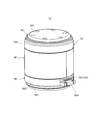
- FIG. 1 is an external perspective view illustrating a vibration actuator according to a first embodiment of the present invention.
- FIG. 2 is a longitudinal sectional view illustrating the vibration actuator according to the first embodiment of the present invention. It is an exploded perspective view of the same vibration actuator. It is a perspective view which shows the movable body and the elastic support part of the same vibration actuator.
- FIG. 5A and FIG. 5B are views showing a coupling state between the elastic support portion and the movable body.
- 6A and 6B are views showing a modification of the state of coupling between the elastic support portion and the movable body. It is a top view of the elastic support part provided with the damping part. It is a fragmentary sectional view of an elastic supporting part provided with a damping part.
- FIG. 6 is a longitudinal sectional view illustrating a vibration actuator according to a second embodiment of the present invention.
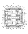
- FIG. 7 is an exploded perspective view of a vibration actuator according to Embodiment 2 of the present invention.
- FIG. 2 is a diagram illustrating an example of an electronic device on which the vibration actuator is mounted.
- FIG. 2 is a diagram illustrating an example of an electronic device on which the vibration actuator is mounted.
- FIG. 1 is an external perspective view showing a vibration actuator according to Embodiment 1 of the present invention
- FIG. 2 is a longitudinal sectional view showing a vibration actuator according to Embodiment 1 of the present invention
- FIG. It is an exploded perspective view of the same vibration actuator.
- FIG. 4 is a perspective view showing a movable body and an elastic support portion of the vibration actuator.
- the “upper” side and the “lower” side in the present embodiment are given for the sake of convenience for easy understanding, and mean one or the other of the vibration directions of the movable body 20 in the vibration actuator 10. That is, when the vibration actuator 10 is mounted on an electronic device (see FIGS. 16 and 17), it may be turned upside down or left and right.
- the vibration actuator 10 shown in FIGS. 1 to 4 is an electronic device, specifically, a portable game terminal device (for example, the game controller GC shown in FIG. 16), or a portable device such as a smartphone (for example, shown in FIG. 17). It is mounted as a vibration source on the portable terminal M) and realizes the vibration function of each device. Further, the vibration actuator 10 may have a function of generating sound by vibration. The vibration actuator 10 is driven, for example, when notifying a user of an incoming call or giving an operational feeling or a sense of reality.
- the vibration actuator 10 of the present embodiment accommodates a movable body 20 (see FIG. 2) in a cylindrical fixed body 50 so as to be able to vibrate in a cylindrical axial direction.
- the vibration actuator 10 itself becomes a vibration body.
- the vibration actuator 10 includes a movable body 20 having a magnet 30 and movable body cores 41 and 42, a fixed body 50 having coils 61 and 62, and a movable body 20 having a fixed body 50. And plate-like elastic support portions 81 and 82 for reciprocating support.
- the coils 61 and 62, the magnet 30, and the movable body cores 41 and 42 constitute a magnetic circuit that vibrates the movable body 20.
- the coils 61 and 62 are energized by power supply from a power supply unit (for example, the drive control unit 203 illustrated in FIGS. 16 and 17), the coils 61 and 62 and the magnet 30 cooperate. Accordingly, the movable body 20 reciprocates with respect to the fixed body 50 in the vibration direction.
- the movable body 20 reciprocates in the axial direction of the coils 61 and 62, that is, in the vibration direction, inside the coils 61 and 62 held by the coil holding unit 52.
- the movable body 20 can reciprocate inside an inner main body (coil protection wall) 522 disposed between the coils 61 and 62 and the movable body 20.
- the inner main body portion 522 is a part of the coil holding portion 52, and details of the coil holding portion 52 will be described later.
- the axial direction of the coils 61 and 62 is the vibration direction of the movable body 20, the magnetization direction of the magnet 30, or the axial direction of the coil holding unit 52.
- the movable body 20 is at the center of the length in the vibration direction of the fixed body 50 (specifically, the coil holding section 52) via the elastic support sections 81 and 82 when the movable body 20 is not moving and is not vibrating. And at predetermined intervals inside the fixed body 50 (more specifically, inside the main body part 522 of the coil holding part 52) in a direction orthogonal to the axial direction of the movable body 20. At this time, it is desirable that the movable body 20 is located at a position where the movable body 20 is balanced with the coils 61 and 62 so as not to contact the inner main body 522 of the coil holding section 52.
- the center of the length in the vibration direction of the magnet 30 and the movable body cores 41 and 42 is opposed to the center of the length in the vibration direction between the coils 61 and 62 in a direction orthogonal to the vibration direction. Preferably, they are arranged.
- the movable body 20 When movable (during vibration), the movable body 20 reciprocates in the vibration direction along the inner peripheral surface 522a of the inner main body 522. Note that a magnetic fluid may be interposed between the inner main body 522 and the movable body 20.
- the movable body 20 is located inside the cylindrical coil holding portion 52 of the fixed body 50 and along the inner peripheral surface 522 a of the inner main body portion 522 by the elastic support portions 81 and 82. It is supported so that it can reciprocate.
- the reciprocating direction is a direction in which a case (hereinafter, referred to as “upper case”) 54 and a case (hereinafter, referred to as “lower case”) 56 that cover the opening of the coil holding unit 52 face each other.
- the movable body 20 has a magnet 30, movable body cores 41 and 42, and spring stoppers 22 and 24.
- the movable body cores 41 and 42 and the spring stoppers 22 and 24 are continuously provided around the magnet 30 toward both sides in the vibration direction.
- the outer peripheral surfaces 20 a of the magnet 30 and the movable body cores 41 and 42 are opposed to each other at a predetermined interval inside the inner peripheral surface 522 a of the inner main body 522.
- the outer peripheral surface 20a reciprocates along the inner peripheral surface 522a without contact.
- the magnet 30 is disposed radially inside the coils 61 and 62 so as to be relatively movable in a vibration direction orthogonal to the radial directions of the coils 61 and 62.
- the magnet 30 is disposed so as to be spaced from the coils 61 and 62 radially inside the coils 61 and 62.
- the “radial direction” is a direction orthogonal to the axes of the coils 61 and 62, and is also a direction orthogonal to the vibration direction.
- the “interval” in the radial direction is an interval between the magnet 30 including the inner main body 522 and the coils 61 and 62, and is an interval that can move in the vibration direction of the movable body 20 without contacting each other.
- the distance between the coils 61 and 62 and the magnet 30 means the distance between the inner main body 522 on the side of the coils 61 and 62 and the magnet 30.
- the magnet 30 is disposed so as to face the center of the inner main body 522 on the radially outer side of the magnet 30.
- the magnet 30 may have a cylindrical shape, a plate shape, or the like as long as the magnet 30 is disposed inside the coils 61 and 62 with two magnetized surfaces directed in the direction in which the axes of the coils 61 and 62 extend.
- the shape may be other than a disk shape.
- the magnet 30 is a disk-shaped magnet, and the axial direction is the vibration direction and the magnetization direction is the magnetization direction. It is desirable that the center of the magnet 30 in the axial direction coincides with the center of the movable body 20 in the axial direction.
- the magnet 30 is magnetized in the vibration direction, and the front and back surfaces 30a and 30b separated in the vibration direction have different polarities.
- ⁇ ⁇ Movable body cores 41 and 42 are provided on the front and back surfaces 30a and 30b of the magnet 30, respectively.
- the movable body cores 41 and 42 are magnetic materials, and the magnet 30 and the coils 61 and 62 together constitute a magnetic circuit, and function as yokes.
- the movable body cores 41 and 42 concentrate the magnetic flux of the magnet 30 and flow it efficiently without leaking, and effectively distribute the magnetic flux flowing between the magnet 30 and the coils 61 and 62.
- the movable body cores 41 and 42 have a function as a body part of the movable body 20 and a function as a weight in the movable body 20 in addition to the function as a part of the magnetic circuit.
- the movable body cores 41 and 42 are formed in the shape of an annular plate, and are arranged so that the outer peripheral surface is flush with the outer peripheral surface of the magnet 30.
- the outer peripheral surface 20a is configured.
- the movable body cores 41 and 42 are laminated cores, for example, are formed by laminating silicon steel plates.
- the movable body cores 41 and 42 are the same members formed similarly, and are provided symmetrically about the magnet 30.
- the movable body cores 41 and 42 are attracted to the magnet 30 and fixed to the magnet 30 by a thermosetting adhesive such as an epoxy resin or an anaerobic adhesive.
- Openings 412, 422 formed in the respective central portions of the movable body cores 41, 42 indicate the axial position of the movable body 20, and are used as joints with the spring stoppers 22, 24.
- the movable body cores 41 and 42 are arranged inside the coils 61 and 62 (in the radial direction) and in a direction perpendicular to the axial direction of the coils 61 and 62. 61, 62.
- the movable body cores 41 and 42, together with the magnet 30, constitute a movable body side magnetic circuit portion in the magnetic circuit.
- the spring stoppers 22 and 24 have a function of fixing the movable body side magnetic circuit section to the elastic support sections 81 and 82. Further, the spring stoppers 22 and 24 are also weights, have a function as weights of the movable body 20, and increase the vibration output of the movable body 20.
- the spring stoppers 22 and 24 have joints 222 and 242 joined to the movable body cores 41 and 42, weight main bodies 224 and 244, and spring fixing parts 226 and 246.
- the spring stoppers 22 and 24 connect the joints 222 and 242, the weight main bodies 224 and 244, and the spring fixing parts 226 and 246 in the vibration direction, respectively, and open in the vibration direction. It is formed in a cylindrical shape having a through hole.
- a weight can be added in this through-hole, so that the through-hole can have a function as a weight adjusting portion together with the weight.
- the joining portions 222 and 242 are joined to the movable body cores 41 and 42, respectively. Specifically, the joints 222 and 242 are inserted into the openings 412 and 422 of the movable body cores 41 and 42, respectively, and are fitted therein. The joints 222 and 242 are fixed in the openings 412 and 422 by, for example, bonding using a thermosetting adhesive such as an epoxy resin or an anaerobic adhesive.
- the weight main bodies 224 and 244 are cylindrical bodies having larger outer diameters than the joining parts 222 and 242 and the spring fixing parts 226 and 246, and have a large mass.
- the weight body portions 224 and 244 are provided at both ends of the movable body 20 that are separated from each other in the vibration direction, and are not provided on the outer peripheral side of the movable body 20.
- the weight main bodies 224 and 244 do not limit the space in which the coils located on the outer peripheral side of the movable body 20 are arranged, and the efficiency of electromagnetic conversion does not decrease. Therefore, the weight of the movable body 20 can be suitably increased, and a high vibration output can be realized.
- the spring fixing portion 226 is located at one end of the movable body 20 in the vibration direction, that is, at the upper end of the movable body 20 and at the inner peripheral portion which is the inner diameter end of the upper leaf spring which is the elastic support portion 81. 802 (see FIG. 4).
- the spring fixing portion 246 is the other end in the vibration direction of the movable body, that is, the lower end of the movable body 20 and the inner end of the lower leaf spring that is the elastic support portion 82.
- the peripheral portion 802 (see FIG. 4) is joined. A detailed description of the elastic support portions 81 and 82 will be described later.
- the spring fixing portions 226 and 246 protrude in the vibration direction from the weight main body portions 224 and 244, respectively, and are joined to the inner peripheral portions 802 and 802 of the elastic support portions 81 and 82 at the tips. Therefore, the elastic support portions 81 and 82 protrude from the weight body portions 224 and 244, and are fixed at the tips of the spring fixing portions 226 and 246 having a step formed with respect to the weight body portions 224 and 244. Due to this step, a clearance as an elastic deformation region in the vibration direction of the elastic support portions 81 and 82 extending outward from the inner peripheral portions 802 and 802 in the outer peripheral direction is secured.
- the spring stoppers 22 and 24 can be fixed parts for fixing a weight or a spring. That is, since the spring stoppers 22 and 24 have a weight (weight) function and a spring fixing function of fixing the elastic support parts 81 and 82, it is not necessary to assemble members having the respective functions. By simply providing the spring stoppers 22 and 24 on the movable body side magnetic circuit unit, the upper leaf spring and the lower leaf spring, which are the elastic support parts 81 and 82, are attached to the movable body 20 having a weight function and a spring fixing function. It can be easily assembled, and the assemblability can be improved.
- the spring stoppers 22 and 24 may be made of a magnetic material, but are preferably made of a non-magnetic material. If the spring stoppers 22 and 24 are made of a non-magnetic material, the magnetic flux from the movable core 41 does not flow upward, and the magnetic flux from the movable core 42 does not flow downward. It can flow to the coils 61 and 62 located on the outer peripheral side of 41 and 42.
- the spring stoppers 22 and 24 may be formed of a material having a higher specific gravity (for example, a specific gravity of about 16 to 19) than a material such as a silicon steel plate (a specific gravity of the steel plate is 7.70 to 7.98). preferable.
- tungsten can be applied to the material of the spring stoppers 22 and 24.
- the fixed body 50 supports the movable body 20 movably in the vibration direction (the same direction as the coil axis direction and the magnetization direction) via the elastic support portions 81 and 82 inside the coils 61 and 62.
- the fixed body 50 in addition to the coils 61 and 62, includes a coil holding portion 52, an upper case (may be referred to as a "first case") 54, and a lower case (referred to as a "second case"). And an electromagnetic shield part 58.
- the coil holding section 52 holds the coils 61 and 62 arranged at a predetermined interval so as to surround the magnet 30 and guides the movement of the movable body 20.
- the coil holding portion 52 is a cylindrical body formed of resin or the like, is disposed radially inside the coils 61 and 62, and has an inner main body portion 522 interposed between the coils 61 and 62 and the magnet 30. Have.
- the inner main body portion 522 is arranged on the inner diameter side of the coils 61 and 62 at a distance from the magnet 30. The inner main body 522 obstructs contact between the magnet 30 and the coils 61 and 62.
- the coil holding portion 52 includes, in addition to the inner main body portion 522, an outer main body portion 524 which is a concentric tubular body arranged to surround and surround the outer peripheral side of the inner main body portion 522, and the inner main body portion 522 and the outer main body portion 524 and a central annular portion 526 that connects the central annular portion 526 with the central annular portion 526.
- an outer main body portion 524 which is a concentric tubular body arranged to surround and surround the outer peripheral side of the inner main body portion 522, and the inner main body portion 522 and the outer main body portion 524 and a central annular portion 526 that connects the central annular portion 526 with the central annular portion 526.
- the outer main body 524 is arranged so as to surround the coils 61 and 62 disposed on the outer peripheral surface of the inner main body 522, and the outer peripheral surface of the outer main body 524 is covered by a cylindrical electromagnetic shield 58.
- the outer body 524 is closed by the upper and lower cases 54 and 56 while sandwiching the outer peripheral portions 806 of the elastic support portions 81 and 82 together with the upper and lower cases 54 and 56 at both open ends (upper and lower ends). By closing both ends of the outer main body 524 with the upper and lower cases 54 and 56, respectively, a hollow vibration actuator housing is formed.
- the center annular portion 526 has a disk shape that is provided between the inner main body portion 522 and the outer main body portion 524 at the center position in the axial direction (the vibration direction). That is, the outer main body portion 524, the inner main body portion 522, and the central annular portion 526 form pockets (coil insertion portions) each having a concave cross section that open in a circular shape at both ends in the axial direction in the coil holding portion 52. I have.
- the central annular portion 526 forms the bottom of the pocket.
- the coils 61 and 62 are fixed in the concave pockets, respectively, while being accommodated therein.
- the inner body 522 is a cylindrical body, and the movable body 20 is arranged on the inner peripheral side so as to be able to reciprocate in the axial direction.
- the coils 61 and 62 are arranged in the axial direction (coil) so as to surround the outer peripheral surface of the inner body 522. (Axial direction).
- the inner peripheral surface 522a of the inner main body 522 is disposed facing the outer peripheral surface of the movable body 20 at a predetermined interval.
- the predetermined interval is an interval at which the movable body 20 can move in the axial direction, which is the vibration direction, without contacting the inner peripheral surface 522a when moving in the vibration direction.
- the movable body 20 moves along the inner peripheral surface 522a without contact.
- the thickness of the inner main body portion 522 is preferably smaller than the thickness of the outer main body portion 524. Even if the moving movable body 20 comes in contact with the outer main body portion 522, the inner main body portion 522 has a thickness that does not affect the outer peripheral coils 61 and 62 at all. is there. That is, the durability of the coil holding portion 52 that holds the coils 61 and 62 mainly depends on the radial thickness of the inner main body 522, the axial length of the central annular portion 526, and the diameter of the outer main body 524. Secure by thickness in the direction.
- the coil wire connecting the coils 61 and 62 held apart in the axial direction by the coil holding portion 52 is provided in the coil holding portion 52 and has a guide groove communicating between pockets (slits) having a concave cross section. (Not shown).
- the coils 61 and 62 are connected to the outside by turning a coil connection portion 521 below the coil holding portion 52.
- the coil connection portion 521 is located on the protrusion 564 of the lower case 56.
- the guide groove is provided, for example, on the outer peripheral portion of the central annular portion 526.
- the coils 61 and 62 are inserted into pockets (slits) having a concave cross section that are formed by the inner main body portion 522, the outer main body portion 524, and the central annular portion 526 and that open on both sides in the axial direction. It is fixed by bonding or sealing.
- the coils 61 and 62 are fixed to the inner main body 522, the outer main body 524, and the central annular part 526 by bonding. Therefore, the coils 61 and 62 can increase the bonding strength with the coil holding portion 52, and even when a large impact is applied, the coils 61 and 62 are damaged as compared with the configuration in which the movable body directly contacts the coil. None.
- the coils 61 and 62 generate the drive source of the vibration actuator 10 together with the magnet 30 and the movable body cores 41 and 42 in the vibration actuator 10 with the axial direction of the coils 61 and 62 (magnetization direction of the magnet 30) as the vibration direction. Used for The coils 61 and 62 are energized during driving and constitute a voice coil motor together with the magnet 30.
- the coils 61 and 62 are constituted by self-welding wire coils in the present embodiment. Accordingly, when the vibration actuator 10 is assembled to the coil holding portion 52, the cylindrical shape can be inserted and held in a pocket having a concave cross section, which is a slit, so that the coil wire is not unraveled and the assembling property of the vibration actuator 10 can be improved. Improvements are being made.
- the coil axes of the coils 61 and 62 are arranged coaxially with the axis of the coil holding portion 52 or the axis of the magnet 30.
- the center position of the length in the coil axis direction (vibration direction) is set to the center of the length in the vibration direction of the movable body 20 (specifically, the vibration direction of the magnet 30).
- the position is held so as to be substantially the same position (including the same position) in the vibration direction.
- the coils 61 and 62 according to the present embodiment are configured to be wound in opposite directions to each other, and configured to allow current to flow in the opposite direction when energized.
- Both ends of the coils 61 and 62 are connected to a power supply unit (for example, the drive control unit 203 shown in FIGS. 16 and 17).
- a power supply unit for example, the drive control unit 203 shown in FIGS. 16 and 17.
- both ends of the coils 61 and 62 are connected to an AC supply unit, and AC power (AC voltage) is supplied to the coils 61 and 62 from the AC supply unit.
- AC power AC voltage
- the magnet 30 is mounted such that the front surface 30a on one side (upper side in the present embodiment) of the magnetizing direction is an N pole, and the back surface 30b on the other side (lower side in the present embodiment) of the magnetizing direction is an S pole.
- a magnetic flux radiated from the movable core 41 on the front surface 30a side of the magnet 30 and incident on the movable core 42 on the back surface 30b side of the magnet 30 is formed.
- the light is emitted from the surface side of the magnet 30, radiated from the movable body core 41 on the upper side of the magnet 30 to the coil 61 side, passes through the electromagnetic shield part 58, and passes through the coil 62 through the lower side of the magnet 30.
- the flow of the magnetic flux entering the magnet 30 from the body core 42 is formed.
- the magnetic flux traverses the coils 61 and 62 in the radial direction with respect to any part of the coils 61 and 62 arranged so as to surround the magnet 30 and the movable body cores 41 and 42.
- Lorentz force acts in the same direction (for example, the ⁇ f direction shown in FIG. 11) along the magnetization direction.
- the upper case 54 and the lower case 56 are each formed in a cylindrical shape with a bottom, and the respective bottoms 541 and 561 constitute the top and bottom surfaces of the vibration actuator 10 in the present embodiment.
- the upper case 54 and the lower case 56 may be formed by forming a metal plate into a concave shape by drawing.
- the electromagnetic shield part 58 is a cylindrical magnetic body disposed so as to cover the outer periphery of the coil holding part 52.
- the electromagnetic shield part 58 functions as an electromagnetic shield and prevents leakage of magnetic flux to the outside of the vibration actuator 10.
- the electromagnetic shield portion 58 functions as a magnetic circuit together with the coils 61 and 62, the magnet 30, and the movable cores 41 and 42, the thrust constant can be increased and the electromagnetic conversion efficiency can be increased.
- the electromagnetic shield portion 58 has a function as a magnetic spring together with the magnet 30 by utilizing the magnetic attraction of the magnet 30.
- the magnet 30 is arranged inside the electromagnetic shield portion 58 such that the center of the magnet 30 in the vibration direction is located at the center of the length of the electromagnetic shield portion 58 in the vibration direction.
- the magnetic attraction force F1 acts between the magnet 30 and the electromagnetic shield portion 58, respectively.
- the magnetic attraction F2 is generated between the magnet 30 and the electromagnetic shield part 58, and the movable body 20 It returns to the original position by the force of the thrust F3.
- the total spring constant is the sum of the spring constants of the leaf springs serving as the elastic support portions 81 and 82 and the spring constant of the magnetic spring by the magnet 30 and the electromagnetic shield portion 58.
- the spring constant of the leaf spring can be reduced.
- the stress of the leaf spring is reduced, the adverse effect on the life is suppressed, and the reliability of the vibration actuator 10 can be increased.
- the bottom part 541 of the upper case 54 and the bottom part 561 of the lower case 56 are disk-shaped bodies, and the inside of the cylindrical peripheral wall parts 542 and 562 rising from the outer peripheral edge of each of the bottom parts 541 and 561 has an opening edge. Also, an annular step portion extending in the circumferential direction is provided at a position near the bottom portions 541 and 561 (see FIG. 2).
- the outer surfaces of the peripheral wall portions 542 and 562 are provided so as to be flush with the outer surface of the electromagnetic shield portion 58 surrounding the coils 61 and 62. Accordingly, the vibration actuator 10 is formed in a substantially cylindrical shape (barrel shape) having a flat outer peripheral surface and has a small and simple shape, so that the installation space can be configured with a simple cylindrical shape.
- the upper case 54 and the lower case 56 are fitted with both open ends of the coil holding portion 52 at the steps, respectively, and are fixed by sandwiching the outer peripheral portions 806 of the elastic support portions 81 and 82 with the open ends.
- the length from the bottoms 541 and 561 to the step can respectively define the movable range of the movable body 20.
- the movable range of the movable body 20 is configured so that the movable body 20 vibrates within the movable range due to deformation of the elastic support portions 81 and 82.
- the upper case 54 and the lower case 56 of the fixed body 50 are hard-stopped (movable range limited) via a movable body space having a length from the bottom parts 541 and 561 to the step part to which the elastic support parts 81 and 82 are fixed. It has a function as a movable range suppressing mechanism that becomes HS. That is, the movable body space is defined to have a length within a range in which the elastic support portions 81 and 82 are not plastically deformed. Accordingly, even when a force exceeding the movable range is applied to the movable body 20, the elastic support portions 81 and 82 come into contact with the fixed body 50 without being plastically deformed, so that the elastic support portions 81 and 82 are damaged. And reliability can be improved.
- the elastic support portions 81 and 82 are provided so as to sandwich the movable body 20 in the vibration direction of the movable body 20 and to be orthogonal to both the movable body 20 and the fixed body 50 in the vibration direction. Are supported on the fixed body 50 so as to be reciprocally movable in the vibration direction.
- the elastic support portions 81 and 82 are separated from each other at both ends of the movable body 20 that are separated in the vibration direction, and are connected to the fixed body 50.
- inner peripheral portions 802 are fitted respectively corresponding to both ends (spring fixing portions 226 and 246) of the movable body 20 which are separated in the axial direction (vibration direction), and The portion 806 is mounted so that the side thereof protrudes radially outward (radially).
- the elastic support portions 81 and 82 support the movable body 20 so as not to contact the fixed body 50 when the movable body 20 is not vibrating and when the movable body 20 is vibrating. In addition, even if the elastic support portions 81 and 82 come into contact with the inner peripheral surface 522a of the inner main body portion 522 of the movable body 20 during driving, the magnetic circuit, specifically, the coils 61 and 62 may not be damaged. Absent.
- the elastic support portions 81 and 82 may be configured as long as they elastically support the movable body 20 movably.
- the elastic support portions 81 and 82 may be a non-magnetic material or a magnetic material (specifically, a ferromagnetic material).
- the elastic support portions 81 and 82 may be configured using stainless steel plates such as SUS304 and SUS316 as long as they are nonmagnetic leaf springs. If the elastic supporting portions 81 and 82 are magnetic materials, a stainless steel plate such as SUS301 can be used.
- the elastic support portions 81 and 82 are arranged at positions in the vibration actuator that are hardly affected by the magnetic field of the magnetic circuit in the movable body 20, even if the material of the elastic support portions 81 and 82 is a non-magnetic material, Alternatively, it may be a magnetic material. Further, when the elastic support portions 81 and 82 are arranged at positions in the movable body 20 that are easily affected by the magnetic field of the magnetic circuit, the material of the elastic support portions 81 and 82 is a non-magnetic material. Is preferred.
- a magnetic material for example, SUS301
- a non-magnetic material for example, SUS304, SUS316
- the material of the elastic support portions 81 and 82 is, for example, A magnetic material (ferromagnetic material) such as SUS301 is used. Therefore, in the present embodiment, the elastic support portions 81 and 82 have high durability and are inexpensive as compared with the case where a nonmagnetic material is used, and can realize the vibration actuator 10 having excellent durability at low cost. I have.
- the elastic support portions 81 and 82 are a plurality of flat plate springs, respectively, as shown in FIG.
- the movable body 20 may have the plurality of elastic support portions 81 and 82 as three or more leaf springs. These leaf springs are attached along a direction orthogonal to the vibration direction.
- the elastic support portions 81 and 82 which are leaf springs, are joined by an arc-shaped deformation arm 804 in which an annular inner peripheral portion 802 as an inner spring end and an outer peripheral portion 806 as an outer spring end are elastically deformed.
- the shape has Due to the deformation of the deformable arm 804, the inner peripheral portion 802 and the outer peripheral portion 806 are relatively displaced in the axial direction.
- Outer peripheral portions 806 of the elastic support portions 81 and 82 are joined to the fixed body 50, and inner peripheral portions 802 are joined to the movable body 20.
- the leaf springs serving as the elastic support portions 81 and 82 are formed by sheet metal processing using a stainless steel plate, and more specifically, a thin flat disk-shaped spiral spring. Since the elastic support portions 81 and 82 have a flat plate shape, the positional accuracy, that is, the processing accuracy can be improved as compared with the conical spring.
- the plurality of elastic support portions 81 and 82 have the same spiral direction, and the outer peripheral portion 806, which is one end on the outer peripheral side, is fixed to the fixed body 50 and the inner peripheral side.
- a plurality of spiral leaf springs are used as the plurality of elastic support portions 81 and 82, and the leaf springs are attached to both ends of the movable body 20 that are separated in the vibration direction.
- the vibration actuator 10 when the movable body 20 is elastically supported with respect to the fixed body 50, if the moving amount of the movable body 20 is large, the movable body 20 is slightly rotated while rotating in the translation direction (here, in this case). , On a plane perpendicular to the vibration direction). If the directions of the vortices of the plurality of leaf springs are opposite to each other, the plurality of leaf springs will move in the buckling direction or the pulling direction, and smooth movement will be hindered.
- the elastic support portions 81 and 82 of the present embodiment are fixed to the movable body 20 so that the directions of the spirals are the same, even if the moving amount of the movable body 20 increases, the elastic support portions 81 and 82 move smoothly. , Can be deformed, have a larger amplitude, and increase the vibration output.
- the elastic support portions 81 and 82 are formed at the ends of the movable body 20 that are separated from each other in the vibration direction of the movable body 20 (the vertical direction in the present embodiment), and a step is formed in the outer peripheral portion from the weight main bodies 224 and 244. And fixed to the tips of the spring fixing portions 226 and 246 protruding. Since the elastic support portions 81 and 82 are arranged so as to extend from the tips of the spring fixing portions 226 and 246 in a direction orthogonal to the vibration direction, an elastic deformation region is secured by the steps. Therefore, the elastic supporting portion can be formed at low cost, and the reliability of the vibration actuator using the elastic supporting portion can be improved.
- the elastic support portions 81 and 82 and the movable body 20 are firmly joined via the fixed pins 26 and 28, respectively, so as not to come off due to the vibration of the movable body 20.
- the fixing pins 26 and 28 shown in FIGS. 2 to 4 have flanges 264 and 284 at the opening edges on one end side of the cylindrical pin bodies 262 and 282 which can be press-fitted into the spring fixing portions 226 and 246, respectively.
- FIG. 5A and FIG. 5B are views showing a connected state between the elastic support portions 81 and 82 and the movable body 20.
- FIG. 5A when fixing the plate-like elastic support portions 81 and 82 to the movable body 20, each inner peripheral portion 802 of the elastic support portions 81 and 82 is attached to the end of the movable body 20 in the vibration direction. Are superimposed on the spring fixing portions 226 and 246.
- the respective pin bodies 262, 282 of the fixing pins 26, 28 are inserted into the through holes opened by the spring fixing parts 226, 246 through the openings of the inner peripheral parts 802, 802 of the plate-like elastic support parts 81, 82. Press in.
- the flanges 264 and 284 hold the inner peripheral portions 802 of the elastic support portions 81 and 82 between the spring fixing portions 226 and 246 as shown in FIG. It is firmly joined to the parts 226, 246.
- the inner peripheral portions 802 of the elastic support portions 81 and 82 and the spring fixing portions 226 and 246 may be joined by welding, bonding, or caulking, or by combining welding, bonding, or caulking. Good.
- FIG. 6A and 6B are views showing a modification of the state of coupling between the elastic supporting portions 81 and 82 and the movable body 20.
- FIG. 6A and 6B the spring fixing portions 226 and 246 of the spring stoppers 22A and 24A, which are configured similarly to the spring stoppers 22 and 24, It has cylindrical caulking portions 228 and 248 protruding from the periphery of the through hole that opens on the direction side.
- the caulking portions 228 and 248 are inserted into the openings of the inner peripheral portions 802 of the elastic support portions 81 and 82, as shown in FIG. 6A.
- the outer periphery of the cylindrical caulking portions 228, 248 have a diameter that fits inside the inner peripheral portion 802 of the elastic support portions 81, 82.
- the length of the caulking portions 228 and 248 protruding from the surface on which the inner peripheral portion 802 is placed is longer than the thickness of the elastic support portions 81 and 82.
- the inner peripheral portions 802, 802 are inserted into the caulking portions 228, 248, and the caulking portions 228, 248 are crushed and caulked, so that the elastic support portions 81, 82 and the spring fixing portions are formed. 226 and 246 are firmly joined.
- This configuration can reduce the number of components, reduce the number of assembling steps, and facilitate manufacture, as compared with the configuration using the fixing pins 26 and 28 shown in FIG. Further, the joint between the elastic support portions 81 and 82 and the spring fixing portions 226 and 246 may be welded or bonded together with the caulking joint.
- the outer peripheral portion 806 of the elastic support portion 81 has an inner peripheral side portion (an inner peripheral side step portion) of the opening in the peripheral wall portion 542 of the upper case 54 on the radial outside.
- the coil holding portion 52 is fixed to the fixed body 50 by being sandwiched by the opening end of the outer main body portion 524.
- the outer peripheral portion 806 of the elastic support portion 82 is radially outside, and has an open end of the outer main body portion 524 in the coil holding portion 52 and a step portion inside the opening in the peripheral wall portion 562 of the lower case 56. And is fixed to the fixed body 50.
- the elastic support portions 81 and 82 are orthogonal to the vibration direction by the upper and lower opening ends of the outer main body portion 524 of the coil holding portion 52 and the upper and lower cases 54 and 56 that fit and close these opening ends. It is pinched while being arranged in the direction.
- the elastic support portions 81 and 82 are provided on the deformable arm 804 or the deformable arm 804 and the outer peripheral portion 806 with a damping portion (damper) 72 as damping means for damping vibration generated in the elastic support portions 81 and 82. Is attached.
- the damping means suppresses the resonance peak in the elastic support portions 81 and 82 and generates stable vibration over a wide range.
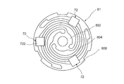
- FIG. 7 is a plan view of an elastic support portion 81 having a damping portion
- FIG. 8 is a partial cross-sectional view of the elastic support portion having a damping portion 72.
- the elastic support portion 82 also includes the damping portion 72, but is configured in the same manner as the elastic support portion 81, and a description thereof will be omitted.
- the damping portion 72 of the present embodiment has an H-shaped cross-section in which the central portions of a pair of flanges 722 arranged in parallel and opposed to each other are connected by ribs (pressing portions) 724.
- Elastic member such as an elastomer.
- the damping portion 72 is arranged while being in contact with both by inserting an elastomer into the bridge portion of the elastic support portion 81 which is a leaf spring, in this embodiment, between the outer peripheral portion 806 and the deformable arm 804.
- the plurality of damping portions 72 are attached to the elastic support portion 81 without being fixed.
- the damping section 72 as a damping means attenuates sharp spring resonance in the elastic support section 81, and prevents a large difference in vibration depending on the frequency due to a remarkable increase in the vibration near the resonance frequency. Accordingly, the movable body 20 vibrates so as not to contact the bottom portions 541 and 561 before the plastic deformation, and no abnormal noise is caused by the contact.
- the damping portion 72 may be formed of any shape, material, or the like as long as it prevents generation of sharp vibration in the elastic support portions 81 (82).
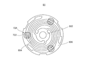
- FIG. 9 and FIG. 10 are a plan view and a partial cross-sectional view of an elastic support portion having a damping portion 72A as a modification.
- the damping portion 72A shown in FIGS. 9 and 10 is an elastomer having a T-shaped cross section, and has a plate-like flange 722 and a pushing portion 724A provided to protrude from the center of the flange 722.
- the damping portion 72A inserts the pushing portion 724A from one surface side of the elastic support portion 81 between the spring portions, specifically, between the outer peripheral portion 806 and the deformable arm 804, and connects the flange 722 between the spring portions. It is positioned over the bridge.
- the attachment portion 73 is a thermosetting resin or an adhesive that does not adhere to the elastic support portion 81, and has a shape such that the push portion 724A does not come off from the spring portion on the back side of the elastic support portion 81. Fixed. With this configuration, the damping portion 72A can reduce the component cost compared to the damping portion 72 having the H-shaped cross section, realize the same damping effect as the damping portion 72, suppress the resonance peak, and generate stable vibration over a wide range. it can.
- the movable body 20 is considered to correspond to a mass portion in a spring-mass system vibration model. Therefore, when the resonance is sharp (has a steep peak), the vibration is attenuated to thereby sharpen the vibration. Suppress peaks. By reducing the vibration, the resonance is no longer sharp, and the maximum amplitude value and the maximum movement amount of the movable body 20 at the time of resonance do not vary, and a vibration with a suitable stable maximum movement amount is output.
- the magnetic circuit shown in FIG. 11 is formed.
- the coils 61 and 62 are arranged such that the coil axes are orthogonal to the magnetic fluxes of the movable body cores 41 and 42 sandwiching the magnet 30 in the vibration direction. Therefore, when the coils 61 and 62 are energized as shown in FIG. 11, the interaction between the magnetic field of the magnet 30 and the current flowing through the coils 61 and 62 causes the coils 61 and 62 to move in the ⁇ f direction according to Fleming's left-hand rule. Lorentz force occurs.
- the Lorentz force in the -f direction is a direction orthogonal to the direction of the magnetic field and the direction of the current flowing through the coils 61 and 62. Since the coils 61 and 62 are fixed to the fixed body 50 (coil holding part 52), a force opposite to the Lorentz force in the ⁇ f direction is applied to the movable body 20 having the magnet 30 by the action-reaction law. It occurs as a thrust in the direction. As a result, the movable body 20 having the magnet 30 moves in the F direction, that is, toward the bottom 541 of the upper case 54.
- the vibration actuator 10 includes a fixed body 50 having coils 61 and 62, a movable body 20 magnetized in the axial direction of the coils 61 and 62 and having a magnet 30 disposed radially inside the coils 61 and 62, Plate-like elastic support portions 81 and 82 for elastically holding the movable member 20 in the vibration direction.
- an inner main body 522 is provided between the outer peripheral surface 30a of the movable body 20 and the coils 61, 62, and the elastic supporting portions 81, 82 allow the movable body 20 to move when the movable body 20 is not vibrated and when the movable body 20 vibrates. It is supported so that it does not touch sometimes.
- the movable body 20 is supported with respect to the fixed body 50 with a gap between the movable body 20 and the inner body 522 during non-vibration in a non-movable state and during movement, that is, during vibration. 20 does not come into contact with the fixed body 50 during the movement, that is, during the vibration.
- the movable body 20 contacts the inner main body 522 only when an impact is applied to the vibration actuator 10 itself, such as when the vibration actuator 10 is dropped. That is, only when there is an impact, the movable body 20 and the inner body 522 relatively move within the range between the outer peripheral surface 20a of the movable body 20 and the inner peripheral surface 522a of the inner body 522, and the movable body 20 Is in contact with the inner main body 522, and its movement is regulated.
- the vibration actuator 10 unlike the conventional vibration actuator, when the shock is applied to the vibration actuator 10, the movable body 20 is displaced and comes into contact with the inner wall of the fixed body, so that no shock is applied. That is, the coils 61 and 62 of the fixed body 50 are not damaged by the impact. Further, the movement of the movable body 20 is regulated by the inner main body 522 due to the impact, and the elastic supports 81 and 82 themselves are not deformed by the impact, and the movable body 20 caused by the deformation of the elastic supports 81 and 82 is movable. Inconveniences such as inability can be resolved. In addition, since the vibration actuator 10 has a structure in which the movable body 20 is reciprocated without sliding on the shaft, it is needless to say that no sliding noise occurs with the shaft when the movable body 20 moves.
- the vibration actuator 10 it is possible to output a suitable bodily sensation vibration having high impact expression and high vibration expression power.
- the vibration actuator 10 is driven by an AC wave input to the coils 61 and 62 from a power supply unit (for example, the drive control unit 203 illustrated in FIGS. 16 and 17). That is, the energizing direction of the coils 61 and 62 is periodically switched, and the thrust in the F direction on the bottom 541 side of the upper case 54 and the thrust in the ⁇ F direction on the bottom 561 side of the lower case 56 are alternately applied to the movable body 20. Works. Thereby, the movable body 20 vibrates in the vibration direction (the winding axis direction orthogonal to the radial direction of the coils 61 and 62 or the magnetization direction of the magnet 30).
- a power supply unit for example, the drive control unit 203 illustrated in FIGS. 16 and 17. That is, the energizing direction of the coils 61 and 62 is periodically switched, and the thrust in the F direction on the bottom 541 side of the upper case 54 and the thrust in the ⁇ F direction on the bottom 561 side of the
- the mass of the movable body 20 m [kg]
- the spring constant of the spring (elastic support portions 81, 82 is a spring) and K sp
- movable body 20 the fixed body With respect to 50, it vibrates at a resonance frequency fr [Hz] calculated by the following equation (1).
- the spring - it is considered to constitute the mass portion in the vibration model of the mass system, when an AC wave of frequency equal to the resonant frequency f r of the movable member 20 is input to the coil 61, the movable member 20 Is in a resonance state. That is, the coil 61 from the power supply unit, by inputting an AC wave of a frequency substantially equal to the resonance frequency f r of the movable member 20, thereby the movable member 20 efficiently vibrated.
- the equations of motion and the circuit equations showing the driving principle of the vibration actuator 10 are shown below.
- the vibration actuator 10 is driven based on a motion equation represented by the following equation (2) and a circuit equation represented by the following equation (3).
- the vibration actuator 10 the energization of the AC wave corresponding to the resonance frequency f r which is determined by the spring constant K sp of the elastic support portions 81, 82 is the mass m and the leaf spring of the movable member 20 to the coil 61, 62 Is performed, a large vibration output can be obtained efficiently.
- the vibration actuator 10 satisfies the equations (2) and (3) and is driven by a resonance phenomenon using a resonance frequency represented by the equation (1). Accordingly, in the vibration actuator 10, the power consumed in the steady state is only the loss due to the damping unit 72, and the vibration actuator 10 can be driven with low power consumption, that is, the movable body 20 can be linearly reciprocated with low power consumption.
- the plate-like elastic support portions 81 and 82 are arranged above and below (in the vibration direction) of the movable body 20, so that the movable body 20 is driven stably in the up and down direction, and The magnetic flux of the coils 61 and 62 can be efficiently distributed from the upper and lower elastic support portions 81 and 82.
- high-output vibration can be realized as the vibration motor.
- the fixed body 50 has a coil holding part 52 that also has a function of holding the coils 61 and 62 and a function of protecting the coils 61 and 62 against the movable body 20. Accordingly, even when the vibration actuator 10 receives an impact, the fixed body 50 withstands the impact and does not damage the elastic support portions 81 and 82 such as deformation. In addition, since impact is transmitted to the coils 61 and 62 via the resin-made inner main body 522, damage can be suppressed, and the vibration actuator 10 has high reliability.
- FIG. 14 is a longitudinal sectional view showing a vibration actuator according to Embodiment 2 of the present invention
- FIG. 15 is an exploded perspective view of the vibration actuator according to Embodiment 2 of the present invention.
- the vibration actuator 10A shown in FIG. 14 and FIG. 15 has the same basic configuration as the vibration actuator 10 corresponding to the first embodiment shown in FIG. 1 to FIG. Only the part 52A is changed.
- the vibration actuator 10 ⁇ / b> A has the same operation and effect as the configuration similar to the vibration actuator 10.
- the same components are denoted by the same reference numerals, and duplicate description will be omitted. That is, in the vibration actuator 10A shown in FIGS. 14 and 15, the movable body 20A is accommodated in the cylindrical fixed body 50A so as to be vibrated in the cylindrical axial direction. When the movable body 20A moves, the vibration actuator 10A itself becomes a vibration body.
- the vibration actuator 10A has a movable body 20A having the magnet 30 and the movable body cores 41 and 42, a fixed body 50A having the coils 61 and 62, and a plate-shaped member for supporting the movable body 20A reciprocally with respect to the fixed body 50A. And the elastic support portions 81 and 82.
- the vibration actuator 10A holds the coils 61 and 62 on the outer peripheral side of the coil holding section 52A in the cylindrical coil holding section 52A arranged to surround the outer circumference of the magnet 30.
- the coil holding portion 52A has a cylindrical shape, has a radially outward opening on the outer peripheral side, and has a concave coil mounting portion 522A on which the coils 61 and 62 are arranged.
- the coil mounting portion 522A is formed by ribs 528A, 528A, and 526A that protrude from the outer surface of the cylindrical portion at an interval in the axial direction.
- the coils 61 and 62 disposed in the coil mounting portion 522A are surrounded by an electromagnetic shield portion 58 surrounding the outer peripheral surface of the coil holding portion 52A, and are fixed in the coil mounting portion by adhesion or the like in a sealed state.
- the coil mounting portion 522A is formed in a concave shape that extends in the circumferential direction and opens radially outward on the outer periphery of the coil holding portion 52A, the coils 61 and 62 can be inserted from the radial outside. It also functions as a simple coil insertion part.
- the coils 61 and 62 are arranged by winding a coil wire from the outside of the coil holding unit 52A and winding the coil wire around the coil holding unit 52A. Therefore, in order to maintain the cylindrical coils 61 and 62, the coils 61 and 62 can be assembled without using a self-fusing wire, and the same operation and effect as those of the first embodiment can be obtained, and the cost of the coils 61 and 62 themselves can be reduced. Thus, the cost of the entire vibration actuator 10A can be reduced.
- FIG. 16 and 17 are diagrams illustrating an example of a mounting form of the vibration actuators 10 and 10A.
- FIG. 16 shows an example in which the vibration actuator 10 is mounted on a game controller GC
- FIG. 17 shows an example in which the vibration actuator 10 is mounted on a portable terminal M.
- the game controller GC is connected to the game machine body by wireless communication, for example, and is used when the user grips or grips it.
- the game controller GC has a rectangular plate shape, and the user grasps the left and right sides of the game controller GC with both hands to operate.
- the game controller GC notifies the user of a command from the game machine body by vibration.
- the game controller GC includes a function other than command notification, for example, an input operation unit for the game machine body.
- the mobile terminal M is, for example, a mobile communication terminal such as a mobile phone or a smartphone.
- the mobile terminal M notifies the user of an incoming call from an external communication device by vibration, and also realizes various functions of the mobile terminal M (for example, a function for giving a feeling of operation and a sense of presence).
- the game controller GC and the portable terminal M respectively include a communication unit 201, a processing unit 202, a drive control unit 203, and vibration actuators 10B and 10C that are vibration actuators 10 as drive units. 10D.
- a plurality of vibration actuators 10B and 10C are mounted.
- the vibration actuators 10B, 10C, and 10D are, for example, parallel to the main surface of the terminal and a plane orthogonal to the vibration direction of the vibration actuators 10B, 10C, and 10D, here, the bottom surface of the lower case 56. It is implemented so that The main surface of the terminal is a surface that comes into contact with the body surface of the user, and in the present embodiment, means a vibration transmission surface that transmits vibration by contacting the body surface of the user.
- the vibration actuators 10B, 10C are arranged such that the vibration direction is orthogonal to the surface where the user's fingertip, the pad of the finger, the palm of the hand touches, or the surface on which the operation unit is provided. Is implemented.
- the vibration actuator 10D is mounted such that the vibration direction is orthogonal to the display screen (touch panel surface). Thereby, the vibration in the direction perpendicular to the main surfaces of the game controller GC and the mobile terminal M is transmitted to the user.
- the communication unit 201 is connected to an external communication device by wireless communication, receives a signal from the communication device, and outputs the signal to the processing unit 202.
- the external communication device is a game machine main body as an information communication terminal, and performs communication in accordance with a short-range wireless communication standard such as Bluetooth (registered trademark).
- the external communication device is, for example, a base station, and performs communication according to the mobile communication standard.
- the processing unit 202 converts the input signal into a drive signal for driving the vibration actuators 10B, 10C, and 10D by a conversion circuit unit (not shown), and outputs the drive signal to the drive control unit 203. Note that, in the mobile terminal M, the processing unit 202 outputs a drive signal based on a signal input from various communication units (not shown, for example, an operation unit such as a touch panel) in addition to a signal input from the communication unit 201. Generate.
- the drive control unit 203 is connected to the vibration actuators 10B, 10C, and 10D, and has a circuit for driving the vibration actuators 10B, 10C, and 10D.
- the drive control unit 203 supplies a drive signal to the vibration actuators 10B, 10C, and 10D.
- the vibration actuators 10B, 10C, and 10D are driven according to a drive signal from the drive control unit 203. Specifically, in the vibration actuators 10B, 10C, and 10D, the movable body 20 vibrates in a direction orthogonal to the main surfaces of the game controller GC and the portable terminal M.
- the movable body 20 may contact the bottom 541 of the upper case 54 or the bottom 561 of the lower case 56 via a damper every time it vibrates.
- the impact on the bottom 541 of the upper case 54 or the bottom 561 of the lower case 56 due to the vibration of the movable body 20, that is, the impact on the housing is directly transmitted to the user as vibration.
- the plurality of vibration actuators 10B and 10C since the plurality of vibration actuators 10B and 10C are mounted, one or both of the plurality of vibration actuators 10B and 10C can be simultaneously driven in accordance with the input drive signal. it can.
- the bodily sensation vibration for the user can be applied by one or both of the vibration actuators 10B and 10C, and a highly expressive vibration such as selectively applying at least a strong or weak vibration can be applied.
- the vibration actuators 10 and 10A according to the present invention can be used by mobile devices other than the game controller GC and the mobile terminal M described in the embodiment (for example, a mobile information terminal such as a tablet PC, a mobile game terminal, and a user). It is suitable when applied to a wearable terminal that is worn and used.
- the vibration actuators 10 and 10A according to the present invention may be used as an exciter that is a vibration device that emits sound by vibration.
- the exciter is a vibrating speaker having a function of making sound by bringing a vibrating surface into contact with an object without using a cone, for example.
- the vibration actuators 10 and 10A according to the present invention may be an exciter that emits sound to cancel and reduce external noise, for example, road noise. Further, the vibration actuators 10 and 10A according to the present invention may be used as a vibration generator. Further, the vibration actuators 10 and 10A of the present embodiment can be used not only for the above-described portable device but also for an electric beauty appliance that requires vibration, such as a facial massage device.
- the vibration actuator according to the present invention has impact resistance, can output a suitable bodily sensation vibration, and is mounted on an electronic device such as a game machine terminal that imparts vibration to a user, an exciter as a vibration device that emits sound, or a portable terminal. It is useful as what is done.
Landscapes
- Engineering & Computer Science (AREA)
- Power Engineering (AREA)
- Physics & Mathematics (AREA)
- Electromagnetism (AREA)
- Mechanical Engineering (AREA)
- Apparatuses For Generation Of Mechanical Vibrations (AREA)
- Reciprocating, Oscillating Or Vibrating Motors (AREA)
- User Interface Of Digital Computer (AREA)
Abstract
Description
ヨークは磁石とともに磁界発生体を構成し、この磁界発生体の磁界内に、コイルが他方の板状弾性体に取り付けた状態で配置されている。このコイルに発振回路を通じて周波数の異なる電流が切替えて付与されることにより一対の板状弾性体は選択的に共振されて振動を発生し、ヨークは枠体内で枠体の中心線方向で振動する。
コイルを有する固定体と、
前記コイルの径方向内側に、前記径方向と直交する振動方向に相対移動可能に配置されるマグネットを有する可動体と、
前記可動体を前記固定体に対して可動自在に支持する弾性支持部を有し、給電される前記コイルと前記マグネットの協働により、前記可動体が前記固定体に対して振動する振動アクチュエータであって、
前記固定体は、前記可動体を囲むように配置され、前記コイルを保持するコイル保持部を有し、
前記コイル保持部は、前記コイルの内径側に、前記マグネットから間隔をあけて配置され、前記マグネットと前記コイルとの接触を阻害するコイル保護壁部を有し、
前記弾性支持部は、前記可動体を前記振動方向で挟むように前記コイル保持部と前記可動体との間に架設された少なくとも2つ以上の板ばねを有し、
前記板ばねは、前記可動体が、前記可動体の非振動時及び振動時に、前記コイル保持部に接触しないよう、振動方向で移動自在に支持する構成を採る。
上記構成の振動アクチュエータを実装した構成を採る。
[振動アクチュエータの全体構成]
図1は、本発明の実施の形態1に係る振動アクチュエータを示す外観斜視図であり、図2は、本発明の実施の形態1に係る振動アクチュエータを示す縦断面図であり、図3は、同振動アクチュエータの分解斜視図である。また、図4は、同振動アクチュエータの可動体と弾性支持部とを示す斜視図である。なお、本実施の形態における「上」側、「下」側は、理解しやすくするために便宜上付与したものであり、振動アクチュエータ10における可動体20の振動方向の一方、他方を意味する。すなわち、振動アクチュエータ10が電子機器(図16及び図17参照)に搭載される際には上下が逆になっても左右になっても構わない。
振動アクチュエータ10は、図2~図4に示すように、マグネット30及び可動体コア41、42を有する可動体20と、コイル61、62を有する固定体50と、可動体20を固定体50に対して往復動自在に支持させる板状の弾性支持部81、82と、を有する。
可動体20は、図2~図4に示すように、固定体50の筒状のコイル保持部52の内側で、且つ、弾性支持部81、82により内側本体部522の内周面522aに沿って往復移動可能に支持される。この往復移動可能な方向は、コイル保持部52の開口を塞ぐケース(便宜上、以下「上ケース」という)54及びケース(便宜上、以下「下ケース」という)56が対向する方向である。
可動体20が振動方向に移動する際には、外周面20aが内周面522aに沿って接触することなく往復移動する。
可動体コア41、42は、本実施の形態では、円環平板状に形成され、外周面をマグネット30の外周面と面一となるように配置され、マグネット30の外周面とともに可動体20の外周面20aを構成する。
本実施の形態では、可動体コア41、42は、可動体20の非振動時において、コイル61、62の内側(径方向内側)で、コイル61、62の軸方向と直交する方向で、コイル61、62に対向するように位置する。
なお、可動体コア41、42は、マグネット30とともに磁気回路における可動体側磁気回路部を構成している。
錘本体部224、244は、接合部222、242及びばね固定部226、246よりも外径が大きい筒体であり質量も大きい。
固定体50は、コイル61、62の内側で、弾性支持部81、82を介して可動体20を振動方向(コイル軸方向、着磁方向と同方向)に移動自在に支持する。
固定体50は、本実施の形態では、コイル61、62の他、コイル保持部52、上ケース(「第1ケース」と称してもよい)54、下ケース(「第2ケース」と称してもよい)56及び電磁シールド部58を有する。
コイル保持部52は、樹脂等により形成された筒状体であり、コイル61、62の径方向内側に配置され、コイル61、62とマグネット30との間に介設される内側本体部522を有する。内側本体部522は、コイル61、62の内径側でマグネット30から間隔をあけて、配置される。内側本体部522は、マグネット30とコイル61、62との接触を阻害する。
すなわち、外側本体部524、内側本体部522及び中央円環部526は、コイル保持部52において、軸方向の両端側でそれぞれ円状に開口する断面凹状のポケット(コイル挿入部)を形成している。中央円環部526はポケットの底部を構成する。この凹状のポケット内にコイル61、62が、それぞれ収容された状態で固定されている。
内側本体部522の内周面522aは、可動体20の外周面と所定間隔を空けて対向して配置されている。この所定間隔は、可動体20が、振動方向に移動する際に、内周面522aと接触することなく振動方向である軸方向に移動可能な間隔である。可動体20は、内周面522aに沿って接触することなく移動する。
また、電磁シールド部58は、コイル61、62、マグネット30、可動体コア41,42とともに磁気回路としても機能するため、推力定数を大きくして電磁変換効率を高めることができる。電磁シールド部58は、マグネット30の磁気吸引力を利用して、マグネット30とともに磁気ばねとしての機能を有する。
なお、本実施の形態では、周壁部542、562の外面は、コイル61、62を囲む電磁シールド部58の外面と面一となるように設けられている。これにより、振動アクチュエータ10は、フラットな外周面を有する略円柱状(樽状)に形成されており、小さく簡易な形状であるので、その設置のスペースを円柱状の簡易な形状で構成できる。
弾性支持部81、82は、可動体20の振動方向で、可動体20を挟み、且つ、可動体20と固定体50との双方に振動方向と直交するように架設されており、可動体20を固定体50に対して振動方向に往復移動自在に支持する。
弾性支持部81、82では、可動体20の軸方向(振動方向)で離れる両端部(ばね固定部226、246)にそれぞれ対応して内周部802が嵌合され、可動体20に、外周部806側が径方向外側(放射方向)に張り出すように取り付けられる。
弾性支持部81、82の材料としては、例えば、非磁性材料(例えばSUS304、SUS316)に比べて、磁性材料(例えば、SUS301)の方が、耐久性が高く、安価であることが知られている。
弾性支持部81、82としての板ばねは、本実施の形態では、ステンレス鋼板を用いて板金加工により形成されており、より具体的には、薄い平板円盤状の渦巻型ばねとしている。弾性支持部81、82は平板状であるので、円錐状のばねよりも位置精度の向上、つまり加工精度の向上を図ることできる。
図2~図4に示す固定ピン26、28は、それぞれ、ばね固定部226、246に圧入可能な円筒状のピン本体262、282の一端側の開口縁部に、フランジ264、284を有する。
図5Aに示すように、板状の弾性支持部81、82を可動体20に固定する際に、弾性支持部81、82のそれぞれの内周部802を、可動体20の振動方向の端部を構成するばね固定部226、246に重ねる。次いで、固定ピン26、28のそれぞれのピン本体262、282を、板状の弾性支持部81、82の内周部802、802の開口を介してばね固定部226、246で開口する貫通孔に圧入する。
図6A、図6Bに示す可動体20は、可動体20の構成と比較して、ばね止め部22、24と同様に構成されるばね止め部22A、24Aのばね固定部226、246が、振動方向側に開口する貫通孔の周囲から突出する筒状のカシメ部228、248を有する。
カシメ部228、248は、図6Aに示すように、弾性支持部81、82の内周部802の開口内に挿入される。筒状のカシメ部228、248の外周は、弾性支持部81、82の内周部802に内嵌する径を有することが望ましい。また、カシメ部228、248の内周部802を載置する面からの突出長は、弾性支持部81、82の厚みより長い。
弾性支持部82の外周部806は、図2に示すように、径方向外側で、コイル保持部52における外側本体部524の開口端と、下ケース56の周壁部562における開口部内側の段差部とに挟持されて固定体50に固定されている。
減衰部72は、弾性支持部81(82)における鋭い振動の発生を防止するものであれば、どのような形状、材料等で形成されてもよい。
図9及び図10に示す減衰部72Aは、断面T型形状のエラストマーであり、板状のフランジ722と、フランジ722の中央部から突出して設けられた押し込み部724Aとを有する。
この構成により、減衰部72Aは、断面H型形状の減衰部72よりも部品コストを低減でき、減衰部72と同等の減衰効果を実現して、共振峰を抑え、広範囲にわたり安定した振動を発生できる。


図14は、本発明の実施の形態2に係る振動アクチュエータを示す縦断面図であり、図15は、本発明の実施の形態2に係る振動アクチュエータの分解斜視図である。
すなわち、図14及び図15示す振動アクチュエータ10Aは、円柱状の固定体50A内に、可動体20Aを、円柱状の軸方向で振動可能に収容している。可動体20Aが可動することに振動アクチュエータ10A自体が振動体となる。
振動アクチュエータ10Aは、マグネット30の外周を囲むように配置される筒状のコイル保持部52Aにおいて、コイル61、62をコイル保持部52Aの外周側で保持させている。
図16及び図17は、振動アクチュエータ10、10Aの実装形態の一例を示す図である。図16は、振動アクチュエータ10をゲームコントローラGCに実装した例を示し、図17は、振動アクチュエータ10を携帯端末Mに実装した例を示す。
20、20A 可動体
20a 外周面
22、22A、24、24A ばね止め部
30 マグネット
30a 表面
30b 裏面
41、42 可動体コア(ヨーク)
50、50A 固定体
52、52A コイル保持部
54 上ケース
56 下ケース
58 電磁シールド部
61、62 コイル
72、72A 減衰部
73 取付部
81、82 弾性支持部
201 通信部
202 処理部
203 駆動制御部
226、246 ばね固定部
522a 内周面
522 内側本体部(コイル保護壁部)
522A コイル取付部
524 外側本体部
526 中央円環部
541、561 底部
542、562 周壁部
722 フランジ
724 リブ(押し込み部)
802 内周部
804 変形アーム
806 外周部
Claims (14)
- コイルを有する固定体と、
前記コイルの径方向内側に、前記径方向と直交する振動方向に相対移動可能に配置されるマグネットを有する可動体と、
前記可動体を前記固定体に対して可動自在に支持する弾性支持部を有し、給電される前記コイルと前記マグネットの協働により、前記可動体が前記固定体に対して振動する振動アクチュエータであって、
前記固定体は、前記可動体を囲むように配置され、前記コイルを保持するコイル保持部を有し、
前記コイル保持部は、前記コイルの内径側に、前記マグネットから間隔をあけて配置され、前記マグネットと前記コイルとの接触を阻害するコイル保護壁部を有し、
前記弾性支持部は、前記可動体を前記振動方向で挟むように前記コイル保持部と前記可動体との間に架設された少なくとも2つ以上の板ばねを有し、
前記板ばねは、前記可動体が、前記可動体の非振動時及び振動時に、前記コイル保持部に接触しないよう、振動方向で移動自在に支持する、
振動アクチュエータ。 - 前記可動体は、前記マグネットに、前記可動体の振動方向にそれぞれに固定されるヨークを有し、
前記コイルは、前記マグネット及び2つの前記ヨークを囲むように、前記振動方向に沿って複数設けられている、
請求項1記載の振動アクチュエータ。 - 前記弾性支持部は、平面状の板ばねであり、前記可動体において振動方向で離間する両端部で突出する突部にそれぞれ取り付けられている、
請求項1または2記載の振動アクチュエータ。 - 前記コイル保持部は、前記コイルが挿入され、前記マグネット側から前記コイルを前記コイル保護壁部により覆う挿入部を有する、
請求項1~3のいずれか一項に記載の振動アクチュエータ。 - 前記コイルは自己融着線コイルにて構成されたことを特徴とする、
請求項1記載の振動アクチュエータ。 - 前記コイルは、前記コイル保護壁部の外径側に配置され、前記コイル保護壁部に対して巻き付けられたコイルである、
請求項1記載の振動アクチュエータ。 - 前記固定体には、前記可動体が可動する際の可動範囲を抑制する可動範囲抑制部を有する、
請求項1記載の振動アクチュエータ。 - 前記固定体は、前記コイル保持部の外周を覆う磁性体からなる電磁シールド部を有する、
請求項1記載の振動アクチュエータ。 - 前記電磁シールド部は、前記可動体の前記マグネットとともに磁気ばねの機能を有する、
請求項8記載の振動アクチュエータ。 - 前記弾性支持部と前記可動体とは、フランジ付きピンによる圧入又はカシメ部によるカシメにより固定されている、
請求項1記載の振動アクチュエータ。 - 前記弾性支持部には、弾性変形による振動を減衰する減衰部が設けられている、
請求項1記載の振動アクチュエータ。 - 前記減衰部は、前記弾性支持部の板ばねの外周部と弾性アームとの間に挿入して挟持可能な断面H型形状のエラストマーである、
請求項11記載の振動アクチュエータ。 - 前記減衰部は、前記弾性支持部の板ばねの外周部と弾性アームとの間に挿入して接着可能な断面T型形状のエラストマーである、
請求項11記載の振動アクチュエータ。 - 請求項1から13のいずれか一項に記載の振動アクチュエータを実装した、
電子機器。
Priority Applications (16)
| Application Number | Priority Date | Filing Date | Title |
|---|---|---|---|
| CN202411666427.5A CN119729305A (zh) | 2018-08-28 | 2019-08-28 | 振动致动器及电子设备 |
| CN202111601645.7A CN114337179B (zh) | 2018-08-28 | 2019-08-28 | 振动致动器及电子设备 |
| US17/271,614 US11848586B2 (en) | 2018-08-28 | 2019-08-28 | Vibration actuator with plate springs sandwiched between a coil holding part and cases |
| CN202111601638.7A CN114337177B (zh) | 2018-08-28 | 2019-08-28 | 振动致动器及电子设备 |
| EP25198731.9A EP4631630A3 (en) | 2018-08-28 | 2019-08-28 | Vibration actuator and electronic equipment |
| CN202411666529.7A CN119767221A (zh) | 2018-08-28 | 2019-08-28 | 振动致动器及电子设备 |
| JP2020517611A JP6750825B2 (ja) | 2018-08-28 | 2019-08-28 | 振動アクチュエータ及び電子機器 |
| CN202111601643.8A CN114337178B (zh) | 2018-08-28 | 2019-08-28 | 振动致动器及电子设备 |
| EP19854445.4A EP3846326B1 (en) | 2018-08-28 | 2019-08-28 | Vibration actuator and electronic equipment |
| KR1020217005721A KR20210046682A (ko) | 2018-08-28 | 2019-08-28 | 진동 액추에이터 및 전자기기 |
| CN201980056702.2A CN112640275B (zh) | 2018-08-28 | 2019-08-28 | 振动致动器及电子设备 |
| US17/561,954 US11444524B2 (en) | 2018-08-28 | 2021-12-26 | Vibration actuator and electronic equipment |
| US17/561,953 US11418099B2 (en) | 2018-08-28 | 2021-12-26 | Vibration actuator and electronic equipment |
| US17/561,955 US11515775B2 (en) | 2018-08-28 | 2021-12-26 | Vibration actuator and electronic equipment |
| US17/561,956 US12003156B2 (en) | 2018-08-28 | 2021-12-26 | Vibration actuator with plate springs including planar, spiral deformation arms |
| US18/648,526 US12592624B2 (en) | 2018-08-28 | 2024-04-29 | Vibration actuator with movable body and fixing body having magnetic cylindrical body outside coil with length |
Applications Claiming Priority (2)
| Application Number | Priority Date | Filing Date | Title |
|---|---|---|---|
| JP2018-159790 | 2018-08-28 | ||
| JP2018159790 | 2018-08-28 |
Related Child Applications (5)
| Application Number | Title | Priority Date | Filing Date |
|---|---|---|---|
| US17/271,614 A-371-Of-International US11848586B2 (en) | 2018-08-28 | 2019-08-28 | Vibration actuator with plate springs sandwiched between a coil holding part and cases |
| US17/561,956 Continuation US12003156B2 (en) | 2018-08-28 | 2021-12-26 | Vibration actuator with plate springs including planar, spiral deformation arms |
| US17/561,954 Continuation US11444524B2 (en) | 2018-08-28 | 2021-12-26 | Vibration actuator and electronic equipment |
| US17/561,955 Continuation US11515775B2 (en) | 2018-08-28 | 2021-12-26 | Vibration actuator and electronic equipment |
| US17/561,953 Continuation US11418099B2 (en) | 2018-08-28 | 2021-12-26 | Vibration actuator and electronic equipment |
Publications (1)
| Publication Number | Publication Date |
|---|---|
| WO2020045470A1 true WO2020045470A1 (ja) | 2020-03-05 |
Family
ID=69643569
Family Applications (1)
| Application Number | Title | Priority Date | Filing Date |
|---|---|---|---|
| PCT/JP2019/033638 Ceased WO2020045470A1 (ja) | 2018-08-28 | 2019-08-28 | 振動アクチュエータ及び電子機器 |
Country Status (7)
| Country | Link |
|---|---|
| US (6) | US11848586B2 (ja) |
| EP (2) | EP4631630A3 (ja) |
| JP (13) | JP6750825B2 (ja) |
| KR (1) | KR20210046682A (ja) |
| CN (6) | CN112640275B (ja) |
| TW (1) | TW202033283A (ja) |
| WO (1) | WO2020045470A1 (ja) |
Cited By (16)
| Publication number | Priority date | Publication date | Assignee | Title |
|---|---|---|---|---|
| KR102234342B1 (ko) * | 2020-10-20 | 2021-03-31 | 에이유에스피코리아 주식회사 | 햅틱 엑추에이터 |
| JPWO2022003921A1 (ja) * | 2020-07-02 | 2022-01-06 | ||
| WO2022027121A1 (fr) * | 2020-08-03 | 2022-02-10 | Gilbert Bouchard | Générateur gravitationnel de vibrations acoustiques multifréquences (ggvam) avec résonateur calibré et cylindre de protection anti-transmission |
| US20220045591A1 (en) * | 2018-03-26 | 2022-02-10 | Mitsumi Electric Co., Ltd. | Vibration actuator and electronic equipment |
| EP3993239A1 (de) * | 2020-11-02 | 2022-05-04 | Continental Engineering Services GmbH | Aktuator zur anregung von schwingungen umfassend einen antrieb mit verbesserter dämpfung |
| WO2022102259A1 (ja) * | 2020-11-10 | 2022-05-19 | フォスター電機株式会社 | 振動アクチュエータ |
| US11418099B2 (en) | 2018-08-28 | 2022-08-16 | Minebea Mitsumi Inc. | Vibration actuator and electronic equipment |
| EP4087101A1 (de) * | 2021-04-30 | 2022-11-09 | INS GmbH | Elektrodynamischer energiewandler |
| GB2607085A (en) * | 2021-05-27 | 2022-11-30 | Tatsunosuke Inoue Nicholas | A transducer for producing vibrational movement |
| EP4094849A1 (en) * | 2021-05-27 | 2022-11-30 | Ask Industries Societa' per Azioni | Electromechanical transducer for generating vibrations to be transmitted to an external mounting wall |
| CN116829273A (zh) * | 2021-03-30 | 2023-09-29 | 丰达电机株式会社 | 振动致动器 |
| WO2024034597A1 (ja) * | 2022-08-09 | 2024-02-15 | ミネベアミツミ株式会社 | 非接触触感呈示装置及び非接触触感呈示システム |
| US11943599B2 (en) | 2019-04-11 | 2024-03-26 | Continental Engineering Services Gmbh | Vibration actuator for rigid structures for high-performance bass playback in automobiles |
| US11996752B2 (en) | 2019-11-29 | 2024-05-28 | Groundwave LTD | Transducer for producing vibrational movement |
| WO2024171956A1 (ja) * | 2023-02-17 | 2024-08-22 | ミネベアミツミ株式会社 | 振動アクチュエータ及び電気機器 |
| JP2024533883A (ja) * | 2022-09-09 | 2024-09-13 | エーエーシー マイクロテック(チャンヂョウ)カンパニー リミテッド | 振動モータ |
Families Citing this family (36)
| Publication number | Priority date | Publication date | Assignee | Title |
|---|---|---|---|---|
| GB2572349B (en) * | 2018-03-27 | 2021-08-11 | Perpetuum Ltd | An electromechanical generator for converting mechanical vibrational energy into electrical energy |
| GB2572350B (en) * | 2018-03-27 | 2023-01-25 | Hitachi Rail Ltd | An electromechanical generator for converting mechanical vibrational energy into electrical energy |
| JP7063691B2 (ja) * | 2018-04-06 | 2022-05-09 | フォスター電機株式会社 | 振動アクチュエータ |
| WO2021003602A1 (zh) * | 2019-07-05 | 2021-01-14 | 瑞声声学科技(深圳)有限公司 | 激励器 |
| US20210013786A1 (en) * | 2019-07-08 | 2021-01-14 | West Virginia University | High frequency resonant linear machines |
| US20210067023A1 (en) * | 2019-08-30 | 2021-03-04 | Apple Inc. | Haptic actuator including shaft coupled field member and related methods |
| JP7410791B2 (ja) * | 2020-04-28 | 2024-01-10 | ニデックインスツルメンツ株式会社 | アクチュエータ |
| CN113572333B (zh) * | 2020-04-28 | 2024-03-29 | 日本电产三协株式会社 | 致动器 |
| CN113727252B (zh) * | 2020-05-25 | 2025-05-06 | 歌尔股份有限公司 | 应用装置 |
| EP3916741A1 (en) * | 2020-05-28 | 2021-12-01 | Nederlandse Organisatie voor toegepast- natuurwetenschappelijk Onderzoek TNO | Electromagnetically controlled segmented mirror, electromagnetic actuator for use therein and method for manufacturing the same |
| JP2022049071A (ja) * | 2020-09-16 | 2022-03-29 | 株式会社東芝 | 振動発電機 |
| CN116323014A (zh) * | 2020-10-08 | 2023-06-23 | 卢肯工程有限公司 | 支持共振的机器 |
| CN112271901A (zh) * | 2020-11-13 | 2021-01-26 | 深圳市万至达电机制造有限公司 | 一种高振动强度的音圈震动和音响播放器二合一的电机 |
| JP7550032B2 (ja) * | 2020-11-19 | 2024-09-12 | 株式会社ソニー・インタラクティブエンタテインメント | 筐体内に移動可能な質量体を備えたデバイス |
| CN217388499U (zh) * | 2021-05-06 | 2022-09-06 | 瑞声光电科技(常州)有限公司 | 线性振动电机 |
| KR20230000640A (ko) * | 2021-06-25 | 2023-01-03 | 부전전자 주식회사 | 동축 익사이터의 코일 분리 장착 구조 |
| JP2023006567A (ja) * | 2021-06-30 | 2023-01-18 | ミネベアミツミ株式会社 | 振動装置 |
| JP7827258B2 (ja) * | 2021-06-30 | 2026-03-10 | ミネベアミツミ株式会社 | 振動アクチュエータ及び電気機器 |
| JP7726518B2 (ja) * | 2021-08-06 | 2025-08-20 | ミネベアミツミ株式会社 | 振動アクチュエーター |
| JP7780276B2 (ja) * | 2021-08-31 | 2025-12-04 | フォスター電機株式会社 | アクチュエータ |
| CN114233785A (zh) * | 2021-11-30 | 2022-03-25 | 沈阳航天新光集团有限公司 | 动力吸振装置 |
| FR3130091B1 (fr) * | 2021-12-02 | 2025-02-14 | Commissariat Energie Atomique | Transducteur électromagnétique pour la récupération d’énergie vibratoire |
| EP4454767A4 (en) * | 2021-12-24 | 2025-12-24 | Minebea Mitsumi Inc | ACTUATOR AND ACTUATOR AND SYSTEM WITH PERCEIVABLE OUTPUT |
| JP7807259B2 (ja) * | 2022-02-28 | 2026-01-27 | ニデックプレシジョン株式会社 | 振動アクチュエータ |
| JP7845898B2 (ja) * | 2022-03-31 | 2026-04-14 | ニデック株式会社 | 振動モータ、および触覚デバイス |
| JP2023163729A (ja) * | 2022-04-28 | 2023-11-10 | ミネベアミツミ株式会社 | 振動アクチュエータ及び電気機器 |
| CN120714880A (zh) | 2022-04-28 | 2025-09-30 | 美蓓亚三美株式会社 | 振动致动器以及接触型输入装置 |
| JP2023176492A (ja) * | 2022-05-31 | 2023-12-13 | ミネベアミツミ株式会社 | 振動アクチュエータ及び電子機器 |
| CN115051525B (zh) * | 2022-06-30 | 2025-04-04 | 瑞声光电科技(常州)有限公司 | 线性振动马达 |
| JP2024033110A (ja) * | 2022-08-30 | 2024-03-13 | ニデックインスツルメンツ株式会社 | アクチュエータ |
| JP7654791B2 (ja) * | 2022-11-30 | 2025-04-01 | エーエーシー マイクロテック(チャンヂョウ)カンパニー リミテッド | 振動モータ |
| CN116009059A (zh) * | 2022-12-13 | 2023-04-25 | 上海勘察设计研究院(集团)有限公司 | 一种用于地下管线探测的声频振动法及装置 |
| CN115795578B (zh) * | 2022-12-20 | 2026-03-24 | 中航工业南京伺服控制系统有限公司 | 一种高精度伺服阀线圈电阻及外径计算方法 |
| TWI845076B (zh) * | 2022-12-20 | 2024-06-11 | 士林電機廠股份有限公司 | 鐵芯捲繞機及其膨脹支撐結構 |
| JP2024113574A (ja) * | 2023-02-09 | 2024-08-22 | アルプスアルパイン株式会社 | 振動発生装置 |
| US12573931B1 (en) * | 2024-06-16 | 2026-03-10 | David Deak, SR. | Vibration powered energy harvesting generator with metallic glass layer having high permeability, around coil structure |
Citations (10)
| Publication number | Priority date | Publication date | Assignee | Title |
|---|---|---|---|---|
| JPS59191427U (ja) * | 1983-06-07 | 1984-12-19 | 中央発條株式会社 | 皿ばね |
| JPH09117721A (ja) * | 1994-09-28 | 1997-05-06 | Seiko Instr Inc | 振動モジュール |
| JPH11262234A (ja) * | 1998-03-12 | 1999-09-24 | Daido Steel Co Ltd | 振動発電機 |
| JP2004293334A (ja) * | 2003-03-25 | 2004-10-21 | Toei Denki Kk | リニアモータ駆動型圧縮機、及び、これを用いた冷凍機 |
| JP3748637B2 (ja) | 1996-10-14 | 2006-02-22 | 松下電器産業株式会社 | 携帯機器用振動発生装置 |
| JP2006296127A (ja) * | 2005-04-13 | 2006-10-26 | Alps Electric Co Ltd | 電磁アクチュエータ |
| JP2009033864A (ja) * | 2007-07-26 | 2009-02-12 | Mitsumi Electric Co Ltd | 振動発生装置 |
| JP2013126299A (ja) * | 2011-12-14 | 2013-06-24 | Aisin Seiki Co Ltd | リニアアクチュエータ |
| JP2016013554A (ja) * | 2015-09-24 | 2016-01-28 | 日本電産コパル株式会社 | 振動アクチュエータ |
| JP2018159790A (ja) | 2017-03-22 | 2018-10-11 | 富士ゼロックス株式会社 | 現像剤補給装置及び画像形成装置 |
Family Cites Families (132)
| Publication number | Priority date | Publication date | Assignee | Title |
|---|---|---|---|---|
| US3748637A (en) | 1971-10-22 | 1973-07-24 | C W S Ind Inc | Sonar transducer assembly |
| JPS5725588Y2 (ja) * | 1977-11-30 | 1982-06-03 | ||
| JPS5495818A (en) | 1978-01-09 | 1979-07-28 | Mazda Motor Corp | Rotor cooling equipment of rotary piston engine |
| CA1122638A (en) | 1979-03-13 | 1982-04-27 | Cts Corporation | Linear electromagnetic actuator with permanent magnet armature |
| NL175856C (nl) * | 1979-12-21 | 1987-12-16 | Terra Dynamics B V | Omzetter voor het opnemen van mechanische trillingen en een met een dergelijke omzetter gevormde seismometer, benevens een schakeling voor het in subgroepen onderverdelen van een aantal van zulke seismometers. |
| JPS5831779Y2 (ja) | 1980-11-25 | 1983-07-14 | 弘夫 杉田 | 包み込み両面容器 |
| JPS5831779A (ja) | 1981-08-19 | 1983-02-24 | Nec Corp | サ−マルヘツド |
| JPS5831779U (ja) * | 1981-08-21 | 1983-03-02 | 日立金属株式会社 | 往復駆動装置 |
| JPS59191427A (ja) | 1983-04-12 | 1984-10-30 | 株式会社東芝 | 変化分検出継電器 |
| JP2605686Y2 (ja) * | 1993-11-11 | 2000-07-31 | ティーディーケイ株式会社 | 可動磁石式リニアアクチュエータ |
| US5896076A (en) | 1997-12-29 | 1999-04-20 | Motran Ind Inc | Force actuator with dual magnetic operation |
| JP3363792B2 (ja) | 1998-07-06 | 2003-01-08 | 三洋電機株式会社 | 音響・振動発生装置 |
| US5973422A (en) | 1998-07-24 | 1999-10-26 | The Guitammer Company | Low frequency vibrator |
| CN1177653C (zh) * | 1999-04-16 | 2004-12-01 | 并木精密宝石株式会社 | 震动驱动器 |
| US6501357B2 (en) * | 2000-03-16 | 2002-12-31 | Quizix, Inc. | Permanent magnet actuator mechanism |
| JP3591429B2 (ja) * | 2000-06-22 | 2004-11-17 | オムロンヘルスケア株式会社 | 流量コントロール弁及び血圧計 |
| JP2002021922A (ja) | 2000-07-11 | 2002-01-23 | Delta Tooling Co Ltd | 磁気回路を利用した除振機構 |
| JP2002307012A (ja) * | 2001-04-11 | 2002-10-22 | Citizen Electronics Co Ltd | 多機能型音響装置 |
| IL142779A0 (en) * | 2001-04-24 | 2002-03-10 | Mnde Technologies L L C | Electromagnetic device particularly useful as a vibrator for a fluid pump |
| US6936937B2 (en) * | 2002-06-14 | 2005-08-30 | Sunyen Co., Ltd. | Linear electric generator having an improved magnet and coil structure, and method of manufacture |
| AU2003301464A1 (en) * | 2002-10-16 | 2004-05-04 | Matsushita Refrigeration Company | Linear motor and liner compressor using the same |
| JP4273738B2 (ja) | 2002-10-16 | 2009-06-03 | パナソニック株式会社 | リニアコンプレッサ |
| JP4065769B2 (ja) | 2002-11-29 | 2008-03-26 | アルプス電気株式会社 | 振動発生装置 |
| JP4255124B2 (ja) | 2004-04-05 | 2009-04-15 | 一登 背戸 | 動吸振器 |
| KR100735299B1 (ko) * | 2004-06-23 | 2007-07-03 | 삼성전기주식회사 | 수직진동자 |
| KR100541112B1 (ko) * | 2004-07-01 | 2006-01-11 | 삼성전기주식회사 | 분동내장형 수직진동자 |
| JP2006158135A (ja) * | 2004-11-30 | 2006-06-15 | Nidec Sankyo Corp | リニアアクチュエータ、それを用いたバルブ装置 |
| US7449803B2 (en) * | 2005-03-21 | 2008-11-11 | Sahyoun Joseph Y | Electromagnetic motor to create a desired low frequency vibration or to cancel an undesired low frequency vibration |
| US7576454B2 (en) * | 2005-05-23 | 2009-08-18 | Ciiis, Llc | Multiple magnet coil in gap generator |
| JP2007028713A (ja) * | 2005-07-12 | 2007-02-01 | Toyo Tire & Rubber Co Ltd | リニアアクチュエータ及びそれを用いた防振装置 |
| US7755227B2 (en) * | 2005-10-19 | 2010-07-13 | Alps Electric Co., Ltd. | Vibration generator |
| US7538463B2 (en) * | 2006-01-10 | 2009-05-26 | Citizen Electronics Co., Ltd. | Vibrator |
| GB2438255B (en) * | 2006-02-23 | 2009-10-21 | Citizen Electronics | Vibrator |
| JP2008225690A (ja) * | 2007-03-09 | 2008-09-25 | Sony Corp | 振動体、触覚機能付きの入力装置及び電子機器 |
| GB2439411B (en) * | 2007-04-27 | 2008-07-23 | Perpetuum Ltd | An electromechanical generator for converting mechanical vibrational energy into electrical energy |
| GB2446685B (en) * | 2007-11-27 | 2009-04-01 | Perpetuum Ltd | An electromechanical generator for converting mechanical vibrational energy into electrical energy |
| US8115581B2 (en) * | 2008-04-04 | 2012-02-14 | Correlated Magnetics Research, Llc | Techniques for producing an electrical pulse |
| GB2459269B (en) * | 2008-04-15 | 2010-09-29 | Perpetuum Ltd | An electromechanical generator for, and method of, converting mechanical vibrational energy into electrical energy |
| JP4535172B2 (ja) | 2008-06-25 | 2010-09-01 | ミツミ電機株式会社 | アクチュエータ及びこれを用いた電動歯ブラシ |
| US20110133577A1 (en) * | 2008-08-18 | 2011-06-09 | In Ho Lee | Horizontal linear vibration device |
| JP2010069356A (ja) * | 2008-09-16 | 2010-04-02 | Sanyo Electric Co Ltd | 往復振動器 |
| IT1391362B1 (it) * | 2008-10-06 | 2011-12-13 | Encrea S R L | Generatore miniaturizzato a magneti oscillanti per la produzione di energia elettrica da vibrazioni |
| JP2010104864A (ja) * | 2008-10-28 | 2010-05-13 | Sanyo Electric Co Ltd | 往復振動発生器 |
| US7948124B1 (en) * | 2009-01-28 | 2011-05-24 | The United States Of America As Represented By The Secretary Of The Navy | Electro-magnetic kinetic energy harvesting device using increased magnetic edge area |
| KR101018214B1 (ko) * | 2009-03-16 | 2011-02-28 | 삼성전기주식회사 | 리니어 진동 모터 |
| KR20100116335A (ko) * | 2009-04-22 | 2010-11-01 | 엘지이노텍 주식회사 | 선형 진동기 |
| KR101059599B1 (ko) * | 2009-07-01 | 2011-08-25 | 삼성전기주식회사 | 선형 진동모터 |
| KR101090428B1 (ko) * | 2009-07-07 | 2011-12-07 | 삼성전기주식회사 | 선형 진동자 |
| US9695806B2 (en) * | 2009-07-22 | 2017-07-04 | Vbox, Incorporated | Method of controlling gaseous fluid pump |
| KR101077374B1 (ko) * | 2009-07-22 | 2011-10-26 | 삼성전기주식회사 | 수평 리니어 진동자 |
| KR101084860B1 (ko) * | 2009-07-22 | 2011-11-21 | 삼성전기주식회사 | 수평 리니어 진동자 |
| JP2011067082A (ja) * | 2009-08-19 | 2011-03-31 | Sanyo Electric Co Ltd | 扁平形振動モータ |
| GB2469347B (en) * | 2009-08-26 | 2011-10-05 | Perpetuum Ltd | An electromechanical generator for converting mechanical vibrational energy into electrical energy |
| KR101069997B1 (ko) * | 2009-09-11 | 2011-10-04 | 삼성전기주식회사 | 리니어 진동 모터 |
| KR101077446B1 (ko) * | 2009-09-11 | 2011-10-26 | 삼성전기주식회사 | 수평 리니어 진동자 |
| KR101079448B1 (ko) * | 2009-09-24 | 2011-11-03 | 삼성전기주식회사 | 수평 진동자 |
| KR20110042745A (ko) * | 2009-10-20 | 2011-04-27 | 삼성전기주식회사 | 선형 진동 발생장치 |
| KR101090426B1 (ko) * | 2009-11-02 | 2011-12-07 | 삼성전기주식회사 | 선형 진동자 |
| JPWO2011074579A1 (ja) * | 2009-12-15 | 2013-04-25 | 日本電気株式会社 | アクチュエータ、圧電アクチュエータ、電子機器、並びに振動減衰及び振動方向変換方法 |
| US8704387B2 (en) * | 2010-01-06 | 2014-04-22 | Tremont Electric, Inc. | Electrical energy generator |
| KR101113561B1 (ko) * | 2010-02-08 | 2012-02-24 | 삼성전기주식회사 | 수직진동자 |
| JP5537984B2 (ja) * | 2010-02-16 | 2014-07-02 | 日本電産セイミツ株式会社 | 往復振動発生器 |
| JP5659426B2 (ja) * | 2010-02-16 | 2015-01-28 | 日本電産セイミツ株式会社 | 振動発生装置 |
| JP5327095B2 (ja) * | 2010-02-22 | 2013-10-30 | ブラザー工業株式会社 | 振動発電機 |
| JP5764929B2 (ja) | 2010-04-14 | 2015-08-19 | 株式会社安川電機 | 直動回転アクチュエータ |
| KR101004879B1 (ko) * | 2010-05-25 | 2010-12-28 | 삼성전기주식회사 | 선형 진동자 |
| CA2801088A1 (en) * | 2010-06-07 | 2011-12-15 | David J. Hochberg | Rotational kinetic energy conversion system |
| KR101101506B1 (ko) * | 2010-06-29 | 2012-01-03 | 삼성전기주식회사 | 수평 진동자 |
| JP5496822B2 (ja) * | 2010-08-20 | 2014-05-21 | 東海ゴム工業株式会社 | 能動型制振器とその製造方法 |
| CN101944819B (zh) | 2010-09-16 | 2012-01-11 | 中国科学院宁波材料技术与工程研究所 | 一种永磁直线往复运动机构 |
| US8736129B2 (en) * | 2010-10-21 | 2014-05-27 | Emerson Electric Co. | End caps for stator segments of segmented stator assemblies |
| CN103222169B (zh) * | 2010-11-30 | 2017-03-22 | 精工电子有限公司 | 电磁发电机 |
| US20120146557A1 (en) * | 2010-12-09 | 2012-06-14 | Korea Advanced Institute Of Science And Technology | Vibration generating module, actuator using the same, handheld device, method for generating vibration and recording medium thereof |
| KR101255914B1 (ko) * | 2010-12-31 | 2013-04-23 | 삼성전기주식회사 | 선형 진동모터 |
| JP2012151954A (ja) * | 2011-01-18 | 2012-08-09 | Toshiba Mach Co Ltd | リニアモータ |
| JP5751663B2 (ja) * | 2011-02-01 | 2015-07-22 | ナブテスコ株式会社 | 電気油圧ハイブリッドモータ |
| US8736086B2 (en) * | 2011-03-25 | 2014-05-27 | Tai-Her Yang | Reciprocal vibration type power generator equipped with inner columnar and outer annular magnetic members, a power storage device, a rectifying circuit, and a charging circuit |
| WO2012153631A1 (ja) * | 2011-05-10 | 2012-11-15 | 日本電産セイミツ株式会社 | 振動発生装置 |
| KR101803809B1 (ko) * | 2011-05-18 | 2017-12-04 | 주식회사 이엠텍 | 선형 진동자 |
| KR101354744B1 (ko) * | 2011-08-04 | 2014-01-23 | 삼성전기주식회사 | 선형진동장치 |
| KR101354773B1 (ko) * | 2011-08-04 | 2014-01-23 | 삼성전기주식회사 | 선형진동모터 |
| KR101860775B1 (ko) * | 2011-10-10 | 2018-05-28 | 주식회사 엠플러스 | 선형 진동자 |
| US20130099600A1 (en) * | 2011-10-24 | 2013-04-25 | Lg Innotek Co., Ltd. | Linear vibrator |
| KR20130068262A (ko) | 2011-12-15 | 2013-06-26 | 삼성전기주식회사 | 진동발생장치 |
| FR2984634B1 (fr) | 2011-12-19 | 2014-11-07 | Univ Pierre Et Marie Curie Paris 6 | Actionneur vitrotactile lineaire miniature |
| KR101388868B1 (ko) * | 2012-09-06 | 2014-04-30 | 삼성전기주식회사 | 진동발생장치 |
| JP6036143B2 (ja) * | 2012-10-11 | 2016-11-30 | ミツミ電機株式会社 | 発電装置 |
| KR101969438B1 (ko) * | 2012-11-12 | 2019-04-16 | 주식회사 엠플러스 | 선형진동모터 |
| JP5889259B2 (ja) * | 2013-02-18 | 2016-03-22 | 日本電産コパル株式会社 | リニア型振動アクチュエータ |
| KR102030597B1 (ko) * | 2013-03-15 | 2019-11-08 | 주식회사 엠플러스 | 진동발생장치 및 이를 구비하는 전자장치 |
| JP5766748B2 (ja) * | 2013-06-05 | 2015-08-19 | Thk株式会社 | リニアアクチュエータ |
| WO2015068377A1 (ja) * | 2013-11-07 | 2015-05-14 | パナソニックIpマネジメント株式会社 | 発電装置 |
| JP6023691B2 (ja) * | 2013-11-18 | 2016-11-09 | 日本電産コパル株式会社 | 振動アクチュエータ |
| US9660509B2 (en) * | 2014-01-08 | 2017-05-23 | Mplus Co., Ltd. | Linear vibration actuator |
| US9666348B2 (en) * | 2014-01-21 | 2017-05-30 | Nidec Copal Corporation | Vibration actuator |
| JP6514880B2 (ja) * | 2014-11-26 | 2019-05-15 | 日本電産サンキョー株式会社 | リニアアクチュエータ |
| EP3121946A4 (en) | 2014-03-17 | 2017-08-23 | Nidec Sankyo Corporation | Linear actuator |
| DE102014211949A1 (de) | 2014-06-23 | 2015-12-24 | Contitech Vibration Control Gmbh | Linearaktor, Hydrolager sowie Kraftfahrzeug mit einem derartigen Hydrolager bzw. Linearaktor |
| WO2016010180A1 (ko) * | 2014-07-18 | 2016-01-21 | (주)하이소닉 | 햅틱 엑추에이터 |
| JP6396129B2 (ja) * | 2014-09-05 | 2018-09-26 | 日本電産コパル株式会社 | リニア振動モータの製造方法 |
| KR101670131B1 (ko) * | 2014-09-23 | 2016-10-28 | 한국과학기술원 | 코팅 대전층을 포함하는 접촉 대전 발전기 및 그 생성 방법 |
| JP6365190B2 (ja) | 2014-09-30 | 2018-08-01 | ミツミ電機株式会社 | リニアアクチュエータ及び電動ブラシ、電動切削機及び電動エアポンプ |
| US10333430B2 (en) * | 2014-11-25 | 2019-06-25 | Georgia Tech Research Corporation | Robust triboelectric nanogenerator based on rolling electrification |
| CN204906155U (zh) * | 2015-07-31 | 2015-12-23 | 瑞声光电科技(常州)有限公司 | 振动电机 |
| CN205051551U (zh) * | 2015-07-31 | 2016-02-24 | 瑞声光电科技(常州)有限公司 | 振动电机 |
| JP6553460B2 (ja) * | 2015-09-14 | 2019-07-31 | 日本電産サンキョー株式会社 | リニアアクチュエータ |
| JP6746372B2 (ja) * | 2016-05-13 | 2020-08-26 | 住友理工株式会社 | 電磁式アクチュエータおよび能動型制振装置と能動型防振装置 |
| US10418890B2 (en) * | 2016-05-27 | 2019-09-17 | University Of Southern California | Energy harvester with magnets and self-assembled ferrofluid liquid bearing |
| JP6688681B2 (ja) * | 2016-05-27 | 2020-04-28 | 住友理工株式会社 | 電磁式アクチュエータとそれを用いた能動型制振器、電磁式アクチュエータの製造方法 |
| JP6715101B2 (ja) * | 2016-06-20 | 2020-07-01 | 株式会社東芝 | 振動発電機、振動発電ユニット、振動発電モジュールおよび電気機器 |
| CN106130303B (zh) * | 2016-07-21 | 2019-03-22 | 瑞声科技(新加坡)有限公司 | 线性振动电机 |
| US10890973B2 (en) * | 2016-08-31 | 2021-01-12 | Apple Inc. | Electronic device including multi-phase driven linear haptic actuator and related methods |
| CN206602446U (zh) * | 2016-10-25 | 2017-10-31 | 瑞声科技(新加坡)有限公司 | 线性振动电机 |
| CN110087782B (zh) | 2016-12-20 | 2021-06-18 | 三美电机株式会社 | 振动执行器、可穿戴终端及来电通知功能设备 |
| CN206834963U (zh) * | 2017-04-14 | 2018-01-02 | 瑞声科技(新加坡)有限公司 | 线性振动电机 |
| CN207251424U (zh) * | 2017-04-14 | 2018-04-17 | 瑞声科技(新加坡)有限公司 | 振动电机 |
| CN206834962U (zh) * | 2017-04-14 | 2018-01-02 | 瑞声科技(新加坡)有限公司 | 线性振动电机 |
| CN206834955U (zh) * | 2017-04-14 | 2018-01-02 | 瑞声科技(新加坡)有限公司 | 振动电机 |
| CN206834956U (zh) * | 2017-04-14 | 2018-01-02 | 瑞声科技(新加坡)有限公司 | 线性振动电机 |
| US10622538B2 (en) * | 2017-07-18 | 2020-04-14 | Apple Inc. | Techniques for providing a haptic output and sensing a haptic input using a piezoelectric body |
| US10848044B1 (en) * | 2017-08-14 | 2020-11-24 | The Government Of The United States Of America, As Represented By The Secretary Of The Navy | Linear electromagnetic actuator |
| WO2019098249A1 (ja) * | 2017-11-20 | 2019-05-23 | アルプスアルパイン株式会社 | 振動発生装置 |
| JP7137046B2 (ja) * | 2017-12-28 | 2022-09-14 | ミツミ電機株式会社 | 振動アクチュエーター及び携帯機器 |
| DE202018000352U1 (de) | 2018-01-15 | 2019-01-16 | Ralf Zablowski | Schwingmaschine |
| JP7081791B2 (ja) | 2018-02-28 | 2022-06-07 | ミネベアミツミ株式会社 | 振動アクチュエータ |
| JP7157305B2 (ja) | 2018-03-26 | 2022-10-20 | ミツミ電機株式会社 | 振動アクチュエータ及び電子機器 |
| GB2572351B (en) * | 2018-03-27 | 2020-08-26 | Perpetuum Ltd | An electromechanical generator for converting mechanical vibrational energy into electrical energy |
| GB2572350B (en) * | 2018-03-27 | 2023-01-25 | Hitachi Rail Ltd | An electromechanical generator for converting mechanical vibrational energy into electrical energy |
| GB2572348B (en) * | 2018-03-27 | 2020-08-19 | Perpetuum Ltd | An electromechanical generator for converting mechanical vibrational energy into electrical energy |
| US11848586B2 (en) | 2018-08-28 | 2023-12-19 | Minebea Mitsumi Inc. | Vibration actuator with plate springs sandwiched between a coil holding part and cases |
| DE102020213768A1 (de) * | 2020-11-02 | 2022-05-05 | Continental Engineering Services Gmbh | Aktuator zur Anregung von Schwingungen umfassend einen Antrieb mit verbesserter Dämpfung |
| US11646680B2 (en) * | 2021-09-08 | 2023-05-09 | Honeywell International Inc. | Autonomous wireless multivariant sensor node—AWSN |
-
2019
- 2019-08-28 US US17/271,614 patent/US11848586B2/en active Active
- 2019-08-28 CN CN201980056702.2A patent/CN112640275B/zh active Active
- 2019-08-28 TW TW108130754A patent/TW202033283A/zh unknown
- 2019-08-28 JP JP2020517611A patent/JP6750825B2/ja active Active
- 2019-08-28 KR KR1020217005721A patent/KR20210046682A/ko not_active Withdrawn
- 2019-08-28 CN CN202111601643.8A patent/CN114337178B/zh active Active
- 2019-08-28 EP EP25198731.9A patent/EP4631630A3/en active Pending
- 2019-08-28 EP EP19854445.4A patent/EP3846326B1/en active Active
- 2019-08-28 CN CN202411666529.7A patent/CN119767221A/zh active Pending
- 2019-08-28 CN CN202111601645.7A patent/CN114337179B/zh active Active
- 2019-08-28 CN CN202411666427.5A patent/CN119729305A/zh active Pending
- 2019-08-28 CN CN202111601638.7A patent/CN114337177B/zh active Active
- 2019-08-28 WO PCT/JP2019/033638 patent/WO2020045470A1/ja not_active Ceased
-
2020
- 2020-03-31 JP JP2020064156A patent/JP6717478B1/ja active Active
- 2020-03-31 JP JP2020064139A patent/JP6753571B2/ja active Active
- 2020-07-13 JP JP2020120214A patent/JP6923279B2/ja active Active
- 2020-07-13 JP JP2020120207A patent/JP6927539B2/ja active Active
-
2021
- 2021-07-27 JP JP2021122809A patent/JP6978139B2/ja active Active
- 2021-08-17 JP JP2021132805A patent/JP6993532B2/ja active Active
- 2021-08-17 JP JP2021132804A patent/JP6978140B2/ja active Active
- 2021-08-17 JP JP2021132808A patent/JP6993533B2/ja active Active
- 2021-08-17 JP JP2021132809A patent/JP6993534B2/ja active Active
- 2021-12-08 JP JP2021199221A patent/JP7225357B2/ja active Active
- 2021-12-26 US US17/561,956 patent/US12003156B2/en active Active
- 2021-12-26 US US17/561,954 patent/US11444524B2/en active Active
- 2021-12-26 US US17/561,955 patent/US11515775B2/en active Active
- 2021-12-26 US US17/561,953 patent/US11418099B2/en active Active
-
2023
- 2023-02-07 JP JP2023016931A patent/JP7529825B2/ja active Active
-
2024
- 2024-04-29 US US18/648,526 patent/US12592624B2/en active Active
- 2024-07-24 JP JP2024118818A patent/JP2024133415A/ja active Pending
Patent Citations (10)
| Publication number | Priority date | Publication date | Assignee | Title |
|---|---|---|---|---|
| JPS59191427U (ja) * | 1983-06-07 | 1984-12-19 | 中央発條株式会社 | 皿ばね |
| JPH09117721A (ja) * | 1994-09-28 | 1997-05-06 | Seiko Instr Inc | 振動モジュール |
| JP3748637B2 (ja) | 1996-10-14 | 2006-02-22 | 松下電器産業株式会社 | 携帯機器用振動発生装置 |
| JPH11262234A (ja) * | 1998-03-12 | 1999-09-24 | Daido Steel Co Ltd | 振動発電機 |
| JP2004293334A (ja) * | 2003-03-25 | 2004-10-21 | Toei Denki Kk | リニアモータ駆動型圧縮機、及び、これを用いた冷凍機 |
| JP2006296127A (ja) * | 2005-04-13 | 2006-10-26 | Alps Electric Co Ltd | 電磁アクチュエータ |
| JP2009033864A (ja) * | 2007-07-26 | 2009-02-12 | Mitsumi Electric Co Ltd | 振動発生装置 |
| JP2013126299A (ja) * | 2011-12-14 | 2013-06-24 | Aisin Seiki Co Ltd | リニアアクチュエータ |
| JP2016013554A (ja) * | 2015-09-24 | 2016-01-28 | 日本電産コパル株式会社 | 振動アクチュエータ |
| JP2018159790A (ja) | 2017-03-22 | 2018-10-11 | 富士ゼロックス株式会社 | 現像剤補給装置及び画像形成装置 |
Cited By (37)
| Publication number | Priority date | Publication date | Assignee | Title |
|---|---|---|---|---|
| US20220045591A1 (en) * | 2018-03-26 | 2022-02-10 | Mitsumi Electric Co., Ltd. | Vibration actuator and electronic equipment |
| US11764659B2 (en) * | 2018-03-26 | 2023-09-19 | Mitsumi Electric Co., Ltd. | Vibration actuator and electronic equipment |
| US11418099B2 (en) | 2018-08-28 | 2022-08-16 | Minebea Mitsumi Inc. | Vibration actuator and electronic equipment |
| US12003156B2 (en) | 2018-08-28 | 2024-06-04 | Minebea Mitsumi Inc. | Vibration actuator with plate springs including planar, spiral deformation arms |
| US11848586B2 (en) | 2018-08-28 | 2023-12-19 | Minebea Mitsumi Inc. | Vibration actuator with plate springs sandwiched between a coil holding part and cases |
| JP2024133415A (ja) * | 2018-08-28 | 2024-10-01 | ミネベアミツミ株式会社 | 振動アクチュエータ及び電子機器 |
| US11444524B2 (en) | 2018-08-28 | 2022-09-13 | Minebea Mitsumi Inc. | Vibration actuator and electronic equipment |
| US12592624B2 (en) | 2018-08-28 | 2026-03-31 | Minebea Mitsumi Inc. | Vibration actuator with movable body and fixing body having magnetic cylindrical body outside coil with length |
| US11515775B2 (en) | 2018-08-28 | 2022-11-29 | Minebea Mitsumi Inc. | Vibration actuator and electronic equipment |
| US11943599B2 (en) | 2019-04-11 | 2024-03-26 | Continental Engineering Services Gmbh | Vibration actuator for rigid structures for high-performance bass playback in automobiles |
| US11996752B2 (en) | 2019-11-29 | 2024-05-28 | Groundwave LTD | Transducer for producing vibrational movement |
| JP7217810B2 (ja) | 2020-07-02 | 2023-02-03 | フォスター電機株式会社 | 振動アクチュエータ |
| WO2022003921A1 (ja) * | 2020-07-02 | 2022-01-06 | フォスター電機株式会社 | 振動アクチュエータ |
| JPWO2022003921A1 (ja) * | 2020-07-02 | 2022-01-06 | ||
| US12294272B2 (en) | 2020-07-02 | 2025-05-06 | Foster Electric Company, Limited | Oscillatory actuator |
| WO2022027121A1 (fr) * | 2020-08-03 | 2022-02-10 | Gilbert Bouchard | Générateur gravitationnel de vibrations acoustiques multifréquences (ggvam) avec résonateur calibré et cylindre de protection anti-transmission |
| KR102234342B1 (ko) * | 2020-10-20 | 2021-03-31 | 에이유에스피코리아 주식회사 | 햅틱 엑추에이터 |
| CN114448288A (zh) * | 2020-11-02 | 2022-05-06 | 大陆工程服务有限公司 | 包括具有改进的阻尼的驱动器的用于激励振动的致动器 |
| EP3993239A1 (de) * | 2020-11-02 | 2022-05-04 | Continental Engineering Services GmbH | Aktuator zur anregung von schwingungen umfassend einen antrieb mit verbesserter dämpfung |
| US11973389B2 (en) | 2020-11-02 | 2024-04-30 | Continental Engineering Services Gmbh | Actuator for exciting vibration having at least one electrically conductive ring |
| JP7560326B2 (ja) | 2020-11-10 | 2024-10-02 | フォスター電機株式会社 | 振動アクチュエータ |
| CN116568412A (zh) * | 2020-11-10 | 2023-08-08 | 丰达电机株式会社 | 振动致动器 |
| US12285781B2 (en) | 2020-11-10 | 2025-04-29 | Foster Electric Company, Limited | Oscillatory actuator |
| JP2022076634A (ja) * | 2020-11-10 | 2022-05-20 | フォスター電機株式会社 | 振動アクチュエータ |
| WO2022102259A1 (ja) * | 2020-11-10 | 2022-05-19 | フォスター電機株式会社 | 振動アクチュエータ |
| EP4245430A4 (en) * | 2020-11-10 | 2024-04-17 | Foster Electric Company, Limited | Oscillatory actuator |
| CN116829273A (zh) * | 2021-03-30 | 2023-09-29 | 丰达电机株式会社 | 振动致动器 |
| EP4087101A1 (de) * | 2021-04-30 | 2022-11-09 | INS GmbH | Elektrodynamischer energiewandler |
| GB2607085B (en) * | 2021-05-27 | 2023-11-08 | Groundwaves Ltd | A transducer for producing vibrational movement |
| WO2022248716A1 (en) * | 2021-05-27 | 2022-12-01 | Inoue Nicholas T | A transducer for producing vibrational movement |
| EP4094849A1 (en) * | 2021-05-27 | 2022-11-30 | Ask Industries Societa' per Azioni | Electromechanical transducer for generating vibrations to be transmitted to an external mounting wall |
| GB2607085A (en) * | 2021-05-27 | 2022-11-30 | Tatsunosuke Inoue Nicholas | A transducer for producing vibrational movement |
| US12587080B2 (en) | 2021-05-27 | 2026-03-24 | Groundwaves Ltd | Transducer for producing vibrational movement |
| WO2024034597A1 (ja) * | 2022-08-09 | 2024-02-15 | ミネベアミツミ株式会社 | 非接触触感呈示装置及び非接触触感呈示システム |
| JP2024533883A (ja) * | 2022-09-09 | 2024-09-13 | エーエーシー マイクロテック(チャンヂョウ)カンパニー リミテッド | 振動モータ |
| JP7652804B2 (ja) | 2022-09-09 | 2025-03-27 | エーエーシー マイクロテック(チャンヂョウ)カンパニー リミテッド | 振動モータ |
| WO2024171956A1 (ja) * | 2023-02-17 | 2024-08-22 | ミネベアミツミ株式会社 | 振動アクチュエータ及び電気機器 |
Also Published As
Similar Documents
| Publication | Publication Date | Title |
|---|---|---|
| JP6993532B2 (ja) | 振動アクチュエータ及び電子機器 | |
| JP7157305B2 (ja) | 振動アクチュエータ及び電子機器 |
Legal Events
| Date | Code | Title | Description |
|---|---|---|---|
| ENP | Entry into the national phase |
Ref document number: 2020517611 Country of ref document: JP Kind code of ref document: A |
|
| 121 | Ep: the epo has been informed by wipo that ep was designated in this application |
Ref document number: 19854445 Country of ref document: EP Kind code of ref document: A1 |
|
| ENP | Entry into the national phase |
Ref document number: 20217005721 Country of ref document: KR Kind code of ref document: A |
|
| NENP | Non-entry into the national phase |
Ref country code: DE |
|
| ENP | Entry into the national phase |
Ref document number: 2019854445 Country of ref document: EP Effective date: 20210329 |
|
| WWG | Wipo information: grant in national office |
Ref document number: 2019854445 Country of ref document: EP |