WO2020050320A1 - 溶接方法および溶接装置 - Google Patents
溶接方法および溶接装置 Download PDFInfo
- Publication number
- WO2020050320A1 WO2020050320A1 PCT/JP2019/034801 JP2019034801W WO2020050320A1 WO 2020050320 A1 WO2020050320 A1 WO 2020050320A1 JP 2019034801 W JP2019034801 W JP 2019034801W WO 2020050320 A1 WO2020050320 A1 WO 2020050320A1
- Authority
- WO
- WIPO (PCT)
- Prior art keywords
- sub
- power
- laser
- welding
- power region
- Prior art date
- Legal status (The legal status is an assumption and is not a legal conclusion. Google has not performed a legal analysis and makes no representation as to the accuracy of the status listed.)
- Ceased
Links
Images








Classifications
-
- B—PERFORMING OPERATIONS; TRANSPORTING
- B23—MACHINE TOOLS; METAL-WORKING NOT OTHERWISE PROVIDED FOR
- B23K—SOLDERING OR UNSOLDERING; WELDING; CLADDING OR PLATING BY SOLDERING OR WELDING; CUTTING BY APPLYING HEAT LOCALLY, e.g. FLAME CUTTING; WORKING BY LASER BEAM
- B23K26/00—Working by laser beam, e.g. welding, cutting or boring
- B23K26/02—Positioning or observing the workpiece, e.g. with respect to the point of impact; Aligning, aiming or focusing the laser beam
- B23K26/06—Shaping the laser beam, e.g. by masks or multi-focusing
- B23K26/067—Dividing the beam into multiple beams, e.g. multi-focusing
-
- B—PERFORMING OPERATIONS; TRANSPORTING
- B23—MACHINE TOOLS; METAL-WORKING NOT OTHERWISE PROVIDED FOR
- B23K—SOLDERING OR UNSOLDERING; WELDING; CLADDING OR PLATING BY SOLDERING OR WELDING; CUTTING BY APPLYING HEAT LOCALLY, e.g. FLAME CUTTING; WORKING BY LASER BEAM
- B23K26/00—Working by laser beam, e.g. welding, cutting or boring
- B23K26/02—Positioning or observing the workpiece, e.g. with respect to the point of impact; Aligning, aiming or focusing the laser beam
- B23K26/06—Shaping the laser beam, e.g. by masks or multi-focusing
- B23K26/073—Shaping the laser spot
- B23K26/0734—Shaping the laser spot into an annular shape
-
- B—PERFORMING OPERATIONS; TRANSPORTING
- B23—MACHINE TOOLS; METAL-WORKING NOT OTHERWISE PROVIDED FOR
- B23K—SOLDERING OR UNSOLDERING; WELDING; CLADDING OR PLATING BY SOLDERING OR WELDING; CUTTING BY APPLYING HEAT LOCALLY, e.g. FLAME CUTTING; WORKING BY LASER BEAM
- B23K26/00—Working by laser beam, e.g. welding, cutting or boring
- B23K26/02—Positioning or observing the workpiece, e.g. with respect to the point of impact; Aligning, aiming or focusing the laser beam
- B23K26/06—Shaping the laser beam, e.g. by masks or multi-focusing
- B23K26/064—Shaping the laser beam, e.g. by masks or multi-focusing by means of optical elements, e.g. lenses, mirrors or prisms
- B23K26/0648—Shaping the laser beam, e.g. by masks or multi-focusing by means of optical elements, e.g. lenses, mirrors or prisms comprising lenses
-
- B—PERFORMING OPERATIONS; TRANSPORTING
- B23—MACHINE TOOLS; METAL-WORKING NOT OTHERWISE PROVIDED FOR
- B23K—SOLDERING OR UNSOLDERING; WELDING; CLADDING OR PLATING BY SOLDERING OR WELDING; CUTTING BY APPLYING HEAT LOCALLY, e.g. FLAME CUTTING; WORKING BY LASER BEAM
- B23K26/00—Working by laser beam, e.g. welding, cutting or boring
- B23K26/08—Devices involving relative movement between laser beam and workpiece
-
- B—PERFORMING OPERATIONS; TRANSPORTING
- B23—MACHINE TOOLS; METAL-WORKING NOT OTHERWISE PROVIDED FOR
- B23K—SOLDERING OR UNSOLDERING; WELDING; CLADDING OR PLATING BY SOLDERING OR WELDING; CUTTING BY APPLYING HEAT LOCALLY, e.g. FLAME CUTTING; WORKING BY LASER BEAM
- B23K26/00—Working by laser beam, e.g. welding, cutting or boring
- B23K26/20—Bonding
- B23K26/21—Bonding by welding
- B23K26/24—Seam welding
- B23K26/244—Overlap seam welding
-
- B—PERFORMING OPERATIONS; TRANSPORTING
- B23—MACHINE TOOLS; METAL-WORKING NOT OTHERWISE PROVIDED FOR
- B23K—SOLDERING OR UNSOLDERING; WELDING; CLADDING OR PLATING BY SOLDERING OR WELDING; CUTTING BY APPLYING HEAT LOCALLY, e.g. FLAME CUTTING; WORKING BY LASER BEAM
- B23K26/00—Working by laser beam, e.g. welding, cutting or boring
- B23K26/20—Bonding
- B23K26/32—Bonding taking account of the properties of the material involved
-
- B—PERFORMING OPERATIONS; TRANSPORTING
- B23—MACHINE TOOLS; METAL-WORKING NOT OTHERWISE PROVIDED FOR
- B23K—SOLDERING OR UNSOLDERING; WELDING; CLADDING OR PLATING BY SOLDERING OR WELDING; CUTTING BY APPLYING HEAT LOCALLY, e.g. FLAME CUTTING; WORKING BY LASER BEAM
- B23K2103/00—Materials to be soldered, welded or cut
- B23K2103/02—Iron or ferrous alloys
- B23K2103/04—Steel or steel alloys
-
- B—PERFORMING OPERATIONS; TRANSPORTING
- B23—MACHINE TOOLS; METAL-WORKING NOT OTHERWISE PROVIDED FOR
- B23K—SOLDERING OR UNSOLDERING; WELDING; CLADDING OR PLATING BY SOLDERING OR WELDING; CUTTING BY APPLYING HEAT LOCALLY, e.g. FLAME CUTTING; WORKING BY LASER BEAM
- B23K2103/00—Materials to be soldered, welded or cut
- B23K2103/08—Non-ferrous metals or alloys
- B23K2103/10—Aluminium or alloys thereof
Definitions
- the present invention relates to a welding method and a welding device.
- Laser welding is known as one of the techniques for welding a workpiece made of a metal material.
- Laser welding is a welding method in which laser light is applied to a portion to be welded of a processing target, and the portion is melted by the energy of the laser light.
- a liquid pool of a molten metal material called a molten pool is formed in a portion irradiated with the laser beam, and thereafter, the molten pool is solidified to perform welding.
- a profile of the laser light may be formed depending on the purpose.
- a technique for shaping a profile of the laser beam is known (for example, see Patent Document 1).
- spatter scattered matter
- This spatter is caused by scattering of the molten metal, and it is important to reduce the occurrence of the spatter to prevent processing defects. Since the spatter is a spatter of the molten metal, when spatter occurs, the amount of the metal material at the welding location is reduced. In other words, when the generation of spatters increases, the metal material at the welding location becomes insufficient, which may cause poor strength and the like. Further, the generated spatter adheres to the periphery of the welded portion, but if the spatter subsequently separates and adheres to an electric circuit or the like, the electric circuit becomes abnormal. Therefore, it may be difficult to perform welding on components for electric circuits.
- the present invention has been made in view of the above, and an object of the present invention is to provide a welding method and a welding apparatus capable of suppressing generation of spatter.
- a welding method provides a method for manufacturing a welding target including metal, by irradiating the laser light and the processing target relative to each other.
- the laser beam is swept on the object to be processed while melting the object to be processed of the irradiated portion and welding is performed, and the laser light is applied to the main power region and the main power region.
- the main power region has a power greater than the power of each of the sub power regions, and a power of the main power region;
- the ratio of the power of at least one sub-power region to the sum of the powers is in the range of 144: 1 to 1: 9.
- the metal is iron or alloy steel containing iron, steel or alloy containing steel, or aluminum or alloy containing aluminum.
- the laser beam includes a plurality of the sub power regions, and the plurality of sub power regions are positioned so as to surround at least a part of an outer periphery of the main power region.
- the plurality of sub power regions have a substantially ring shape surrounding the main power region or an arc shape that is a part of a substantially ring shape surrounding the periphery of the main power region.
- the distance between the center of the sub power region and the center of the main power region is in a range from 225 ⁇ m to 900 ⁇ m.
- the laser beam and the object to be processed move relatively.
- the processing target is at least two members to be welded, and when arranging the processing target in an area irradiated with the laser light, the processing target includes the at least two members. It is arranged to overlap, contact, or be adjacent.
- the metal is SUS304.
- the main power region and the sub power region are generated by a beam shaper.
- the beam shaper is a diffractive optical element.
- a welding device includes a laser oscillator, a portion that receives laser light emitted from the laser oscillator, generates laser light, and irradiates the generated laser light toward a processing target and irradiates the laser light.
- An optical head that melts and welds the object to be processed, and performs welding while performing the melting while sweeping the laser light on the object to be processed.
- the power of the main power region is larger than the power of each of the sub power regions, and the sum of the power of the main power region and the power of the at least one sub power region. Are in the range of 144: 1 to 1: 9.
- the object to be processed includes a metal, and the metal is iron, an alloy steel including iron, steel, an alloy including steel, or aluminum or an alloy including aluminum.
- the laser beam includes a plurality of the sub-power regions, and the plurality of sub-power regions are positioned so as to surround at least a part of an outer periphery of the main power region.
- the plurality of sub power regions have a substantially ring shape surrounding the main power region or an arc shape that is a part of a substantially ring shape surrounding the periphery of the main power region.
- a distance between each center of the sub power region and the center of the main power region is in a range from 225 ⁇ m to 900 ⁇ m.
- the laser light and the object to be processed move relatively.
- the welding apparatus is configured such that the object to be processed overlaps, contacts, or is adjacent to at least two members to be welded.
- the welding apparatus includes a beam shaper that generates the main power region and the sub power region.
- the beam shaper is a diffractive optical element.
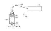
- FIG. 1 is a schematic diagram illustrating a schematic configuration of the laser welding apparatus according to the first embodiment.
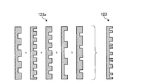
- FIG. 2 is a schematic diagram illustrating a diffractive optical element.
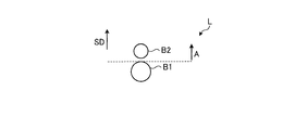
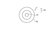
- FIG. 3 is a diagram illustrating an example of a cross-sectional shape of a laser beam.
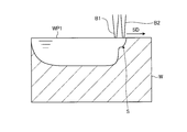
- FIG. 4 is a diagram illustrating a situation where the laser beam melts the processing target.
- FIG. 5A is a schematic diagram illustrating an example of a beam arrangement.
- FIG. 5B is a schematic diagram illustrating an example of a beam arrangement.
- FIG. 5C is a schematic diagram illustrating an example of a beam arrangement.
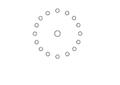
- FIG. 6 is a schematic diagram illustrating the arrangement of a plurality of beams of laser light when the DOE is used.
- FIG. 6 is a schematic diagram illustrating the arrangement of a plurality of beams of laser light when the DOE is used.
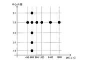
- FIG. 7 is a diagram showing typical conditions under which the irradiation spot state was good in the experiment.
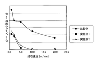
- FIG. 8 is a diagram showing the relationship between the sweep speed and the number of spatters in Comparative Example, Example 1, and Example 2.
- FIG. 9 is a schematic diagram illustrating another example of the beam arrangement.
- FIG. 10 is a schematic diagram illustrating still another example of the arrangement of beams.
- FIG. 11A is a schematic diagram illustrating still another example of the arrangement of beams.
- FIG. 11B is a schematic diagram illustrating still another example of the arrangement of beams.
- FIG. 11C is a schematic diagram illustrating still another example of the arrangement of beams.
- FIG. 11D is a schematic diagram illustrating still another example of the beam arrangement.
- FIG. 11A is a schematic diagram illustrating still another example of the arrangement of beams.
- FIG. 11B is a schematic diagram illustrating still another example of the arrangement of beams.
- FIG. 11C is a schematic diagram illustrating still another example of the
- FIG. 11E is a schematic diagram illustrating still another example of the arrangement of beams.
- FIG. 11F is a schematic diagram illustrating still another example of the arrangement of beams.
- FIG. 11G is a schematic diagram illustrating still another example of the arrangement of beams.
- FIG. 11H is a schematic diagram illustrating still another example of the beam arrangement.
- FIG. 11I is a schematic diagram illustrating still another example of the arrangement of beams.
- FIG. 12 is a schematic diagram illustrating a schematic configuration of the laser welding apparatus according to the second embodiment.
- FIG. 13 is a schematic diagram illustrating a schematic configuration of the laser welding apparatus according to the third embodiment.
- FIG. 14 is a schematic diagram illustrating a schematic configuration of the laser welding apparatus according to the fourth embodiment.
- FIG. 15A is a schematic diagram illustrating an example of a power distribution shape of a laser beam.
- FIG. 15B is a schematic diagram illustrating an example of a power distribution shape of a laser beam.
- FIG. 1 is a schematic diagram illustrating a schematic configuration of the laser welding apparatus according to the first embodiment.
- the laser welding device 100 includes a laser device 110, an optical head 120, and an optical fiber 130 connecting the laser device 110 and the optical head 120.
- the processing target W contains a metal such as iron or aluminum.
- the processing target W is made of, for example, an iron alloy such as stainless steel or an aluminum alloy, and has a plate shape having a thickness of, for example, about 1 mm to 10 mm.
- the laser device 110 includes a laser oscillator, and is configured to output, for example, laser light having a power of several kW.
- the laser device 110 may include a plurality of semiconductor laser elements therein, and may be configured to output a multi-mode laser beam having a power of several kW as a total output of the plurality of semiconductor laser elements.
- the laser device 110 may include various laser light sources such as a fiber laser, a YAG laser, and a disk laser.
- the optical fiber 130 guides the laser light output from the laser device 110 and inputs the laser light to the optical head 120.
- the optical head 120 is an optical device for irradiating the laser light input from the laser device 110 toward the processing target W.
- the optical head 120 includes a collimator lens 121 and a condenser lens 122.
- the collimator lens 121 is an optical system for converting the input laser light into parallel light.
- the condensing lens 122 is an optical system for condensing the parallelized laser light and irradiating the laser light L to the processing target W.
- the optical head 120 is configured to be able to change its relative position with respect to the processing target W in order to sweep the laser light L while irradiating the processing target W with the laser light L.
- the method of changing the relative position with respect to the processing target W includes moving the optical head 120 itself, moving the processing target W, and the like. That is, the optical head 120 may be configured to be able to sweep the laser light L with respect to the fixed processing target W.
- the irradiation position of the laser light L from the optical head 120 may be fixed, and the processing target W may be held movably with respect to the fixed laser light L.
- the optical head 120 includes a diffractive optical element 123 as a beam shaper, disposed between the collimator lens 121 and the condenser lens 122.
- the diffractive optical element 123 here is also called DOE (Diffractive @ Optical
- the diffractive optical element 123 can shape the beam shape by bending or superimposing the input laser light in a direction affected by each diffraction grating.
- the diffractive optical element 123 divides the laser light input from the collimator lens 121 into a plurality of beams. Specifically, the diffractive optical element 123 splits the laser beam and generates a main beam and at least one sub beam. At this time, the diffractive optical element 123 generates a main beam and a sub-beam such that at least a part of at least one sub-beam is positioned forward of the main beam in the sweep direction. Thereby, the laser beam L is composed of the main beam and at least one sub-beam.
- the laser beam L formed by the diffractive optical element 123 is composed of a main beam B1 and a sub-beam B2 as shown in FIG. 3 as an example of a cross-sectional shape on a plane perpendicular to the traveling direction of the laser beam L.
- the sweep direction SD is a direction in which the laser light L moves relative to the processing target W.
- the sub beam B2 is located ahead of the main beam B1 in the sweep direction.
- the front of the main beam B1 means an area A defined by a broken line passing through the position of the beam diameter on the front side in the sweep direction of the main beam B1 and perpendicular to the sweep direction SD as shown in FIG.
- the position of the sub beam B2 is not limited to this, and if it is located anywhere in the area A, it can be considered that it is located in front of the main beam B1.
- the main beam B1 and the sub beam B2 have, for example, a Gaussian power distribution in the radial direction of the beam cross section.
- the diameter of a circle representing the main beam B1 and the sub beam B2 is the beam diameter of each beam.
- the beam diameter of each beam is defined as the diameter of a region including the peak of the beam and having an intensity of 1 / e 2 or more of the peak intensity.
- the short axis eg, short axis
- the longer axis eg, major axis
- long axis passes near the center of the beam herein.
- the length of the region where the intensity is 1 / e 2 or more of the peak intensity is defined as the beam diameter.
- the power of each beam is a power in a region including a peak of the beam and having an intensity of 1 / e 2 or more of the peak intensity.
- the power of the main beam B1 is larger than the power of the sub beam B2.
- the power distribution of the main beam B1 has a sharp shape to some extent. If the power distribution of the main beam B1 is sharp to some extent, the penetration depth when melting the processing target W can be increased, so that the welding strength can be secured and the occurrence of poor welding can be more suitably suppressed.
- the beam diameter is used as an index of the sharpness of the main beam B1
- the beam diameter of the main beam B1 is preferably 600 ⁇ m or less, more preferably 400 ⁇ m or less. If the main beam B1 has a sharp shape, the power for realizing the same penetration depth can be reduced and the processing speed can be increased. Therefore, it is possible to reduce the power consumption of the laser welding apparatus 100 and improve the processing efficiency.
- the power distribution of the sub beam B2 may be as sharp as the main beam B1.
- the beam diameter can be designed by appropriately setting the characteristics of the laser device 110, the optical head 120, and the optical fiber 130 to be used. For example, it can be set by setting the beam diameter of the laser beam input from the optical fiber 130 to the optical head 120, or by setting the optical system such as the diffractive optical element 123 and the lenses 121 and 122.
- the processing target W is arranged in an area irradiated with the laser light L. Subsequently, while irradiating the processing target W with the laser light L including the main beam B1 and the sub-beam B2 split by the diffractive optical element 123, the laser light L and the processing target W are relatively moved to make the laser light L , The welding target W is melted and welded at the portion irradiated with the laser beam L.
- the sweep direction is, for example, a front direction or a depth direction in the drawing. Thereby, the processing target W is welded.
- the sub beam B2 is located on the front side in the sweep direction SD with respect to the main beam B1, so that the generation of spatter can be suppressed.
- FIG. 4 is a diagram showing a state in which the laser beam melts the object to be processed.
- the laser beam L is composed of a main beam B1 and a sub-beam B2.
- the power density of the main beam B1 is, for example, a power density that can generate at least a keyhole.
- the keyhole is a depression or a hole generated by the pressure of the metal vapor generated when the processing target W is melted due to the high power density of the laser beam.
- a sub-beam B2 having a lower power than the main beam B1 is located ahead of the main beam B1 having a higher power in the sweep direction SD.
- the power density of the sub beam B2 is a power density that can melt the processing target W in the presence of the main beam B1 or alone. Therefore, a molten pool WP having a region that is shallower than the depth at which the main beam B1 melts is formed as a molten region in front of the position where the main beam B1 is irradiated. This will be referred to as a shallow area S for convenience.
- the melt intensity regions of the main beam B1 and the sub-beam B2 may overlap, but need not necessarily overlap, as long as the melt pools overlap. Before the molten pool formed by the sub-beam B2 is solidified, it is sufficient that the molten strength region formed by the main beam B1 can reach the molten pool.
- the power densities of the main beam B1 and the sub-beam B2 are power densities that can melt the processing target W
- the fusion intensity region is a state in which the processing target W around the main beam B1 or the sub-beam B2 is melted. This refers to the range of the laser beam with the obtained power density.
- the shallow region S exists ahead of the position where the main beam B1 is irradiated, so that the molten pool is located near the irradiation position of the main beam B1.
- WP stabilizes.
- stabilization of the molten pool WP near the irradiation position of the main beam B1 leads to suppression of the generation of the sputter.
- the ratio of the power of the main beam B1 to the power of the sub-beam B2 is preferably in the range of 144: 1 to 1: 9.
- FIGS. 5A to 5C are schematic diagrams illustrating an example of a beam arrangement.
- 5A to 5C show the arrangement of a plurality of beams on the irradiation surface of the processing target W with the laser light L.
- the laser beam L includes a main beam B1 and a plurality of sub-beams B2 split by the diffractive optical element 123.
- the number of the sub beams B2 is 16.
- the 16 sub-beams B2 are located so as to surround the outer periphery of the main beam B1.
- the 16 sub-beams B2 are positioned so as to form a substantially ring shape with a radius between peaks R around the main beam B1. It can also be said that the 16 sub-beams B2 are positioned such that the distance from the center to the apex forms a substantially regular hexagonal shape of R with respect to the main beam B1.
- the plurality of sub-beams B2 may be continuously overlapped to form a substantially ring shape surrounding the periphery of the main beam B1.
- the shape may be an arc shape which is a part of a substantially ring shape surrounding the main beam B1.
- seven sub-beams B2 are located forward of the main beam B1 in the sweep direction SD.
- the two sub beams B2 are located on the side of the main beam B1 in the direction perpendicular to the sweep direction SD. Then, the seven sub-beams B2 are located on the rear side in the sweep direction SD with respect to the main beam B1.
- a part of the sub-beam B2 is located forward of the main beam B1 in the sweep direction SD, and
- the ratio of the power of B1 to the sum of the powers of the sub-beams B2 is within the range of 9: 1 to 1: 9, it is possible to suppress the occurrence of spatter.
- the sub beam B2 is located so as to form a substantially ring shape with the main beam B1 as a center, so that the sweep direction is changed from the sweep direction SD to an arbitrary direction. Also, a part of the sub beam B2 is located on the front side of the changed sweep direction with respect to the main beam B1. Therefore, the effect of suppressing the generation of spatter can be exerted in an arbitrary sweep direction. Also, in the example shown in FIG. 5C, even if the sweep direction is changed to some extent from the sweep direction SD, the effect of suppressing the generation of spatter can be exhibited.
- DOE was prepared.
- the diameter 2R of the ring shape was set to 600 ⁇ m on the surface to be processed. Further, the sweep direction is the upward direction in the drawing.
- the ratio of the power of the main beam to the sum of the powers of the 16 sub beams is 9: 1, 7: 3, 5: 5, 3: 7, 1: 9, respectively, and In each case, the power of the 16 sub-beams is designed to be equal.
- the sweep speed of the laser beam with respect to the processing target was 0.5 m / min, 1 m / min, 2 m / min, 5 m / min, 10 m / min, 20 m / min, or 30 m / min.
- the power ratio (center: outer circumference) in the table indicates the ratio of the power of the main beam to the sum of the powers of the sub-beams.
- the symbols “ ⁇ ” and “ ⁇ ” indicate the determination results of the degree of spatter scattering during the period in which welding was performed for a predetermined length. Specifically, the symbols “ ⁇ ” and “ ⁇ ” indicate how much the volume of the spatter scattered when the DOE is not used (the power ratio is equivalent to 10: 0) is 100%. This shows whether the volume of the spatter has been reduced.
- the symbol “ ⁇ ” indicates that the scattered spatter volume was reduced by 20% or more as compared with the case where DOE was not used.
- the symbol “ ⁇ ” indicates that the scattered spatter volume is reduced as compared with the case where DOE is not used, but the reduction is less than 20%.
- the power ratio is 7: 3
- the diameter 2R of the approximate circular shape formed by the 16 sub-beams on the surface to be processed is 450 ⁇ m, 600 ⁇ m, 800 ⁇ m, 1000 ⁇ m, 1400 ⁇ m, and 1800 ⁇ m.
- the same irradiation experiment as described above was performed using each designed DOE. Note that the sweep speed was 5 m / min.
- the distance between the center of each sub beam and the center of the main beam is about 225 ⁇ m, about 300 ⁇ m, about 400 ⁇ m, about 500 ⁇ m, about 700 ⁇ m, and about 900 ⁇ m.
- FIG. 7 is a diagram showing typical conditions under which the amount of spatter scattered in the above two experiments was reduced.
- the distance (corresponding to the radius R) between each center of the sub beam and the center of the main beam is preferably in the range of 225 ⁇ m to 900 ⁇ m.
- the distance between the center of the sub beam located on the front side in the sweep direction and the center of the main beam is set in a range from 225 ⁇ m to 900 ⁇ m, and the plurality of sub beams and the main beam located on the side or rear side in the sweep direction are set.
- the distance from the center may be a value outside this range.
- FIG. 8 is a diagram showing the relationship between the sweep speed and the number of scattered spatters in Comparative Example, Example 1, and Example 2.
- the horizontal axis is the sweep speed
- the vertical axis is the number of scattered spatters per 1 mm welding length, which is obtained by analyzing and counting images captured by a high-speed camera.
- the comparative example is a case where the DOE in the above experimental example is not used.
- Example 1 a laser beam as shown in FIG. 5C was formed by DOE using a laser welding apparatus having the configuration shown in FIG. 1 in the same manner as in the above-described experimental example, and a stainless steel SUS304 having a thickness of 10 mm was formed.
- the wavelength of the laser light output from the laser device was 1070 nm, and the power was 5 kW.
- the distance (corresponding to radius R) between the center of the main beam and the center of the arc-shaped sub-beam is set to 300 ⁇ m, and the ratio of the power of the main beam to the sum of the powers of the circular sub-beams is 1: 2. It was made to become.
- the arc-shaped sub-beam is obtained by arranging a plurality of sub-beams having substantially the same power in an arc shape to form one arc-shaped sub-beam in which power is continuously distributed.
- Example 2 is a case where the diameter 2R is 600 ⁇ m and the power ratio is 3: 7 in the above experimental example.
- the laser beam is swept over the processing target.
- making the laser beam a main beam and a plurality of sub-beams and setting the ratio of the power of the main beam to the sum of the powers of the plurality of sub-beams to be 144: 1 to 1: 9 is, for example, the case of spot welding.
- the present invention is also effective for welding in which the laser beam is not swept to the object to be processed.
- the distance between the center of each of the plurality of sub beams adjacent to the main beam and the center of the main beam is preferably 225 ⁇ m to 900 ⁇ m.
- a laser beam L1 irradiated to a processing target is divided into a main beam B1 and three sub-beams B2.
- Each of the three sub beams B2 is located on the front side in the sweep direction SD with respect to the main beam B1.
- the power of the main beam B1 is greater than the power of each sub-beam B2.
- the ratio between the power of the main beam B1 and the sum of the powers of the three sub-beams B2 is in the range from 9: 1 to 1: 9. Even with such an arrangement, it is possible to suppress the occurrence of sputter, as in the case of the first embodiment, the experimental examples, and the examples.
- the angle ⁇ formed by a line connecting the center of the main beam B1 and the centers of two adjacent sub-beams B2 is preferably 90 ° or less. , 60 ° or less, more preferably 45 ° or less.
- the shape of the molten pool is preferably close to line symmetry with respect to the sweep direction SD, it is preferable that the three sub-beams B2 are also arranged so as to be line-symmetric with respect to the sweep direction SD.
- the ratio of the main beam to the sum of the powers of the two sub-beams may be 72: 1.
- the ratio of the power of the main beam to the sum of the powers of the two sub-beams may be 72: 1.
- the laser beam is divided into a main beam and three sub-beams using the DOE, and the three sub-beams are positioned on the front side in the sweep direction with respect to the main beam.
- the ratio can take a value of 144: 1 or more.
- the laser beam L2 irradiated to the processing target is divided into a main beam B1, 16 sub beams B2, and 8 sub beams B3.
- the 16 sub-beams B2 constitute a sub-beam group G2, and are positioned so as to form a substantially ring shape with the main beam B1 as a center.
- the eight sub-beams B3 constitute a sub-beam group G3, and are located around the main beam B1 so as to form a substantially ring shape having a smaller diameter than the ring shape formed by the sub beam B2.
- the ratio of the power of the main beam B1 to the sum of the powers of the sub-beams B2 and B3 is in the range from 9: 1 to 1: 9. Even with such an arrangement, it is possible to suppress the occurrence of sputter, as in the case of the first embodiment, the experimental examples, and the examples.
- FIGS. 11A to 11I are schematic diagrams illustrating still another example of the arrangement of beams.
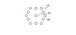
- the laser beam L31 includes a main beam B1 and twelve sub-beams B2.
- the twelve sub beams B2 are positioned so as to form a substantially ring shape or a substantially regular hexagonal shape with the main beam B1 as a center.
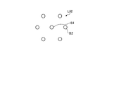
- the laser beam L32 includes a main beam B1 and six sub beams B2.
- the six sub-beams B2 are located so as to form a substantially ring shape or a hexagonal shape around the main beam B1.
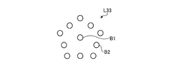
- the laser beam L33 includes a main beam B1 and ten sub beams B2.
- the ten sub beams B2 are located so as to form a substantially ring shape or a pentagonal shape with the main beam B1 as a center.
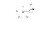
- the laser beam L34 includes a main beam B1 and five sub beams B2.
- the five sub beams B2 are located so as to form a substantially ring shape or a pentagonal shape with the main beam B1 as a center.
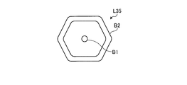
- the laser beam L35 includes a main beam B1 and a sub beam B2.
- the sub-beam B2 has a plurality of sub-beams overlapping so that power is continuously distributed, and is positioned so as to form a substantially ring shape or hexagonal shape with the main beam B1 as a center.
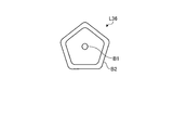
- the laser beam L36 includes a main beam B1 and a sub beam B2.
- the sub-beam B2 has a plurality of sub-beams overlapping so that the power is continuously distributed, and is positioned so as to form a substantially ring shape or a pentagonal shape around the main beam B1.
- the laser beam L37 includes a main beam B1 and 16 sub beams B2.
- the 16 sub-beams B2 are positioned so as to form a substantially ring shape or a substantially regular octagonal shape with the main beam B1 at the center.
- the laser beam L38 includes a main beam B1 and a sub beam B2.
- the sub-beam B2 has a plurality of sub-beams overlapping so that power is continuously distributed, and is positioned so as to form a substantially ring shape or an octagonal shape with the main beam B1 as a center.
- the sweep directions of the laser beams L31 to L38 may be arbitrary, and may be directions deviated from the directions of the pentagon, hexagon or octagon.
- the number of sub-beams that do not exist in the front in the sweep direction may be slightly thinned out if the sub-beams are densely arranged as shown in FIGS. 11A, 11C, and 11G. In the example shown in FIG.
- the laser beam L37 includes a main beam B1 and 16 sub beams B2.
- the sixteen sub beams B2 are located so as to form a substantially ring shape or a substantially octagonal shape with the main beam B1 as a center. Further, when the matrix M is defined, the main beam B1 and the sub beam B2 are arranged so as to fill the rectangular grid.
- FIG. 12 is a diagram illustrating a schematic configuration of a laser welding apparatus according to the second embodiment.
- the laser welding device 200 irradiates the processing target W1 with the laser beam L to perform welding on the processing target W1.
- the processing target W1 is configured by stacking two plate-shaped metal members W11 and W12.
- the laser welding apparatus 200 realizes welding by the same operation principle as the laser welding apparatus 100. Therefore, hereinafter, only the device configuration of the laser welding device 200 will be described.
- the laser welding device 200 includes a laser device 210, an optical head 220, and an optical fiber 230.
- the laser device 210 includes a laser oscillator, is configured in the same manner as the laser device 110, and is configured to output, for example, laser light having a power of several kW.
- the optical fiber 230 guides the laser light output from the laser device 210 and inputs the laser light to the optical head 220.
- the optical head 220 is an optical device for irradiating the laser light input from the laser device 210 toward the processing target W1, like the optical head 120.
- the optical head 220 includes a collimator lens 221 and a condenser lens 222.
- the optical head 220 has a galvano scanner arranged between the condenser lens 222 and the processing target W1.
- the galvano scanner is a device that can control the angle of the two mirrors 224a and 224b to move the irradiation position of the laser beam L without moving the optical head 220 and sweep the laser beam L. is there.
- the laser welding apparatus 200 includes a mirror 226 for guiding the laser beam L emitted from the condenser lens 222 to a galvano scanner. The angles of the mirrors 224a and 224b of the galvano scanner are changed by motors 225a and 225b, respectively.
- the optical head 220 includes a diffractive optical element 223 as a beam shaper, disposed between the collimator lens 221 and the condenser lens 222. Like the diffractive optical element 123, the diffractive optical element 223 splits the laser light input from the collimator lens 221 and generates a main beam and at least one sub-beam. At least one sub-beam is at least partially located forward of the main beam in the sweep direction. The power of the main beam is greater than the power of each sub-beam, and the ratio of the power of the main beam to the sum of the power of at least one sub-beam is in the range of 9: 1 to 1: 9. Thereby, the laser welding apparatus 200 can suppress generation of spatter when welding the processing target W1. The ratio may be in the range from 144: 1 to 1: 9, depending on how the sub-beams are divided and arranged.
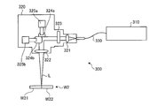
- FIG. 13 is a schematic diagram illustrating a schematic configuration of the laser welding apparatus according to the third embodiment.
- the laser welding apparatus 300 irradiates the processing target W2 with the laser beam L to perform welding on the processing target W2.
- the processing target W2 is configured such that two plate-shaped metal members W21 and W22 are adjacent to each other so as to abut each other.
- the laser welding device 300 includes a laser oscillator, and realizes welding by the same operation principle as the laser welding devices 100 and 200.
- the configuration of the components (the laser device 310 and the optical fiber 330) other than the optical head 320 is the same as the corresponding components of the laser welding devices 100 and 200. Therefore, only the device configuration of the optical head 320 will be described below.
- the optical head 320 is an optical device for irradiating the laser light input from the laser device 310 toward the processing target W2, like the optical heads 120 and 220.
- the optical head 320 includes a collimator lens 321 and a condenser lens 322.
- the optical head 320 has a galvano scanner disposed between the collimator lens 321 and the condenser lens 322.
- the angles of the mirrors 324a and 324b of the galvano scanner are changed by motors 325a and 325b, respectively.
- a galvano scanner is provided at a position different from that of the optical head 220.
- the irradiation position of the laser light L is moved and the laser light L is swept without moving the optical head 320. Can be.
- the optical head 320 includes a diffractive optical element 323 as a beam shaper, which is disposed between the collimator lens 321 and the condenser lens 322.
- the power of the main beam is greater than the power of each sub-beam, and the ratio of the power of the main beam to the sum of the power of at least one sub-beam is in the range of 9: 1 to 1: 9.
- the ratio may be in the range of 144: 1: 1 to 1: 9, depending on how the sub-beams are divided and arranged.
- FIG. 14 is a diagram illustrating a schematic configuration of a laser welding apparatus according to the fourth embodiment.
- a laser welding apparatus 400 according to the fourth embodiment is an example of a configuration of an apparatus that irradiates the processing target W with laser beams L4 and L5 to melt the processing target W.
- the laser welding apparatus 400 realizes a welding method by the same operation principle as the welding apparatus according to the first embodiment. Therefore, hereinafter, only the device configuration of the laser welding device 400 will be described.
- the laser welding apparatus 400 includes a plurality of oscillators 411 and 412 that oscillate laser light, an optical head 420 that irradiates the laser light to the processing target W, and a light that guides the laser light oscillated by the oscillators 411 and 412 to the optical head 420. And fibers 431 and 432.
- the oscillators 411 and 412 are configured to oscillate multi-mode laser light having an output of several kW, for example.
- each of the oscillators 411 and 412 includes a plurality of semiconductor laser elements therein, and is configured to oscillate a multi-mode laser beam having an output of several kW as a total output of the plurality of semiconductor laser elements.
- various lasers such as a fiber laser, a YAG laser, and a disk laser may be used.
- the optical head 420 is an optical device for condensing the respective laser beams L4 and L5 guided from the oscillators 411 and 412 to a power density capable of melting the processing target W and irradiating the processing target W with the laser light L4 and L5. is there.
- the optical head 420 includes a collimating lens 421a and a condenser lens 422a for the laser light L4, and a collimating lens 421b and a condenser lens 422b for the laser light L5.
- the collimating lenses 421a and 421b are optical systems for collimating the laser light guided by the optical fibers 431 and 432, respectively, and the condenser lenses 422a and 422b process the collimated laser light, respectively. This is an optical system for condensing light on the target W.
- the laser beams L4 and L5 on the processing target W are constituted by a main beam and at least one sub main beam having at least a part thereof on the front side in the sweep direction with respect to the main beam.
- the laser beam L4 may be used for forming a main beam
- the laser beam L5 may be used for forming a sub-beam.
- the power of the main beam is greater than the power of each sub-beam, and the ratio of the power of the main beam to the sum of the power of at least one sub-beam is in the range of 9: 1 to 1: 9.
- the ratio may be in the range from 144: 1 to 1: 9, depending on how the sub-beams are divided and arranged.
- only two laser beams L4 and L5 are used.
- the number may be increased as appropriate, and the number of laser beams shown in FIGS. What is necessary is just to be comprised so that a laser beam suitable for implementation of this invention, such as a cross-sectional shape, may be implement
- the laser beams L4 and L5 are generated using the two oscillators 411 and 412.
- laser light output from one resonator may be split into two by an optical splitter to generate laser lights L4 and L5.
- the optical fibers 431 and 432, the collimator lens 421a and the condenser lens 422a, and the collimator lens 421b and the condenser lens 422b are individually provided for each of the two oscillators 411 and 412. .
- the laser light output from each of the two oscillators 411 and 412 is guided to the optical head by a separate core, and the two lasers are used.
- An optical head using a common collimating lens and a condensing lens for light may be used to irradiate two laser beams to a processing target as a configuration of laser beams suitable for implementing the present invention.
- the profile (power distribution shape) of the laser beam has a discrete power region constituted by the main beam and the sub beam.
- the power region is a region having power that contributes to melting of a processing target in a plane perpendicular to the light traveling direction of the laser light.
- each power region alone has a power capable of melting a processing target, and it is sufficient that each power region can melt the processing target by the influence of energy applied to the processing target by another power region.
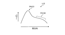
- FIG. 15A shows a power distribution shape in the forward direction of an example of the laser light L12 having a different power distribution shape from the laser light L.
- two power regions PA121 and PA122 arranged in the forward direction are continuous.
- Power region PA121 has a single-peak shape having a peak, and is, for example, a main power region.
- Power region PA122 has a shoulder shape, for example, a sub-power region.
- the boundary between the two power regions PA121 and PA122 in the curve of FIG. 15A can be defined, for example, as the position of an inflection point existing therebetween.
- FIG. 15B shows the power distribution shape in the forward direction of another example of the laser light L13 having a different power distribution shape from the laser light L.
- the two arranged power regions PA131 and PA132 are continuous.
- Each of power regions PA131 and PA132 has a single-peak shape having a peak, and for example, each is a main power region and a sub-power region.
- the boundary between the two power regions PA131 and PA132 in the curve of FIG. 15B can be defined, for example, as the position of a minimum point existing therebetween.
- Each of the laser beams L12 and L13 can be applied as a laser beam composed of the main power region and the sub power region in the present invention.
- the laser beams L12 and L13 can be realized by using, as a beam shaper, an optical component such as a properly designed diffractive optical element or an optical lens or an optical fiber capable of controlling a power distribution.
- the power distribution shapes of other laser beams such as the laser beams L, L ', L ", L1, L2, L31 to L38, which are constituted by the main power region and the sub power region in the present invention, are also beam shapers.
- it can be realized by using an optical component such as a properly designed diffractive optical element or optical lens, or an optical fiber capable of controlling the power distribution.
- the welding mode of the main beam may be a keyhole type welding or a heat conduction type welding.
- the keyhole type welding here is a welding method using a keyhole.
- heat conduction type welding is a welding method in which a processing target is melted using heat generated by absorption of laser light on a surface of the processing target.
- all the sub-beams may have the same power, or one or some sub-beams may have higher power than the other sub-beams.
- a plurality of sub-beams can be classified into a plurality of groups, the sub-beams have substantially the same power within the same group, and the sub-beams may have different powers between groups. In this case, when the sub-beams classified into a plurality of different groups are compared, the powers differ stepwise.
- the number of sub-beams included in a certain group is not limited to a plurality, and may be one. In any case, the ratio of the power of the main beam to the sum of the powers of the plurality of sub-beams is preferably 144: 1 to 1: 9.
- the object to be processed is not limited to a plate material, and the mode of welding is not limited to lap welding or butt welding. Therefore, the object to be processed may be constituted by overlapping, contacting, or adjoining at least two members to be welded.
- sweep may be performed by known wobbling, weaving, output modulation or the like to adjust the surface area of the molten pool.
- the object to be processed may be a metal plate having a thin layer of another metal on the surface of the metal, such as a plated metal plate.
- the one having a thickness of about 1 mm to 10 mm has been exemplified, but it may be thinner, about 0.01 mm, or thicker.
- the present invention is not limited by the above embodiments.
- the present invention also includes a configuration obtained by appropriately combining the components of the above-described embodiments. Further, further effects and modifications can be easily derived by those skilled in the art. Therefore, the broader aspects of the present invention are not limited to the above-described embodiments, and various modifications are possible.
- the present invention can be used for laser welding.
Landscapes
- Physics & Mathematics (AREA)
- Optics & Photonics (AREA)
- Engineering & Computer Science (AREA)
- Plasma & Fusion (AREA)
- Mechanical Engineering (AREA)
- Laser Beam Processing (AREA)
Abstract
溶接方法は、金属を含む加工対象に向かってレーザ光を照射し、照射された部分の前記加工対象を溶融して溶接を行い、前記レーザ光は、主パワー領域と、少なくとも1つの副パワー領域とによって構成され、前記主パワー領域のパワーは、それぞれの前記副パワー領域のパワーより大きく、前記主パワー領域のパワーと、前記少なくとも1つの副パワー領域のパワーの合計との比が、144:1から1:9までの範囲内である。
Description
本発明は、溶接方法および溶接装置に関する。
金属材料からなる加工対象を溶接する手法の一つとして、レーザ溶接が知られている。レーザ溶接とは、レーザ光を加工対象の溶接すべき部分に照射し、レーザ光のエネルギーで当該部分を溶融させる溶接方法である。レーザ光が照射された部分には、溶融池と呼ばれる溶融した金属材料の液溜りが形成され、その後、溶融池が固化することによって溶接が行われる。
また、レーザ光を加工対象に照射する際には、その目的に応じ、レーザ光のプロファイルが成形されることもある。例えば、レーザ光を加工対象の切断に用いる場合に、レーザ光のプロファイルを成形する技術が知られている(例えば特許文献1参照)。
ところで、溶接時には、この溶融池からはスパッタと呼ばれる飛散物が発生することが知られている。このスパッタは、溶融金属が飛散したものであり、その発生を減らすことは加工欠陥を防ぐ上で重要である。スパッタは、溶融金属が飛散したものであることから、スパッタが発生すると溶接個所における金属材料が減少してしまっていることにもなる。つまり、スパッタの発生が多くなると、溶接個所の金属材料が不足してしまい、強度不良等を引き起こすことにもなる。また、発生したスパッタは、溶接個所の周辺に付着することになるが、これがのちに剥離し、電気回路等に付着すると、電気回路に異常をきたしてしまう。したがって、電気回路用の部品に対して溶接を行うことは困難な場合がある。
本発明は、上記に鑑みてなされたものであって、その目的は、スパッタの発生を抑制することができる溶接方法および溶接装置を提供することにある。
上述した課題を解決し、目的を達成するために、本発明の一態様に係る溶接方法は、金属を含む加工対象に向かってレーザ光を照射しながら前記レーザ光と前記加工対象とを相対的に移動させ、前記レーザ光を前記加工対象上で掃引しつつ、照射された部分の前記加工対象を溶融して溶接を行い、前記レーザ光は、主パワー領域と、前記主パワー領域に対して掃引方向前方側に少なくともその一部がある少なくとも1つの副パワー領域とによって構成され、前記主パワー領域のパワーは、それぞれの前記副パワー領域のパワーより大きく、前記主パワー領域のパワーと、前記少なくとも1つの副パワー領域のパワーの合計との比が、144:1から1:9までの範囲内である。
本発明の一態様に係る溶接方法は、前記金属は鉄または鉄を含む合金鋼または鋼または鋼を含む合金またはアルミニウムまたはアルミニウムを含む合金である。
本発明の一態様に係る溶接方法は、前記レーザ光は、複数の前記副パワー領域を含み、前記複数の副パワー領域は、前記主パワー領域の外周の少なくとも一部を囲むように位置する。
本発明の一態様に係る溶接方法は、前記複数の副パワー領域は、前記主パワー領域を囲む略リング形状または前記主パワー領域の周囲を囲む略リング形状の一部である円弧形状を持つ。
本発明の一態様に係る溶接方法は、前記副パワー領域の中心と前記主パワー領域の中心との距離が、225μmから900μmまでの範囲内である。
本発明の一態様に係る溶接方法では、前記レーザ光と前記加工対象とが相対的に移動する。
本発明の一態様に係る溶接方法は、前記加工対象は溶接されるべき少なくとも2つの部材であり、前記加工対象を前記レーザ光が照射される領域に配置する際は、前記少なくとも2つの部材を重ねる、または接触させる、または隣接させるように配置する。
本発明の一態様に係る溶接方法では、前記金属は、SUS304である。
本発明の一態様に係る溶接方法は、ビームシェイパによって、前記主パワー領域と前記副パワー領域とを生成する。
本発明の一態様に係る溶接方法は、前記ビームシェイパは回折光学素子である。
本発明の一態様に係る溶接装置は、レーザ発振器と、レーザ発振器から発振された光を受け取ってレーザ光を生成し、前記生成されたレーザ光を加工対象に向かって照射して照射された部分の前記加工対象を溶融して溶接を行う光学ヘッドと、によって構成され、前記レーザ光を前記加工対象上で掃引しつつ、前記溶融を行なって溶接を行い、前記レーザ光は、主パワー領域と、少なくとも1つの副パワー領域によって構成され、前記主パワー領域のパワーは、それぞれの前記副パワー領域のパワーより大きく、前記主パワー領域のパワーと、前記少なくとも1つの副パワー領域のパワーの合計との比が、144:1から1:9までの範囲内である。
本発明の一態様に係る溶接装置は、前記加工対象は金属を含み、当該金属は鉄または鉄を含む合金鋼または鋼または鋼を含む合金またはアルミニウムまたはアルミニウムを含む合金である。
本発明の一態様に係る溶接装置は、前記レーザ光は、複数の前記副パワー領域を含み、前記複数の副パワー領域は、前記主パワー領域の外周の少なくとも一部を囲むように位置する。
本発明の一態様に係る溶接装置は、前記複数の副パワー領域は、前記主パワー領域を囲む略リング形状または前記主パワー領域の周囲を囲む略リング形状の一部である円弧形状を持つ。
本発明の一態様に係る溶接装置は、前記副パワー領域のそれぞれの中心と前記主パワー領域の中心との距離が、225μmから900μmまでの範囲内である。
本発明の一態様に係る溶接装置では、前記レーザ光と前記加工対象とが相対的に移動する。
本発明の一態様に係る溶接装置は、前記加工対象は溶接されるべき少なくとも2つの部材を重ねる、または接触させる、または隣接させることにより構成される。
本発明の一態様に係る溶接装置は、前記主パワー領域と前記副パワー領域とを生成するビームシェイパを備える。
本発明の一態様に係る溶接装置は、前記ビームシェイパは回折光学素子である。
本発明によれば、スパッタの発生を抑制することができるという効果を奏する。
以下、添付図面を参照しながら、本発明の実施形態を詳細に説明する。なお、以下に説明する実施形態により本発明が限定されるものではない。また、図面の記載において、同一または対応する要素には適宜同一の符号を付している。
(実施形態1)
図1は、実施形態1に係るレーザ溶接装置の概略構成を示す模式図である。レーザ溶接装置100は、レーザ装置110と、光学ヘッド120と、レーザ装置110と光学ヘッド120とを接続する光ファイバ130と、を備えている。また、加工対象Wは、鉄やアルミニウム等の金属を含むものである。加工対象Wは、たとえばステンレス鋼等の鉄合金や、アルミニウム合金からなり、厚さがたとえば1mmから10mmまでの範囲内程度の板状である。
図1は、実施形態1に係るレーザ溶接装置の概略構成を示す模式図である。レーザ溶接装置100は、レーザ装置110と、光学ヘッド120と、レーザ装置110と光学ヘッド120とを接続する光ファイバ130と、を備えている。また、加工対象Wは、鉄やアルミニウム等の金属を含むものである。加工対象Wは、たとえばステンレス鋼等の鉄合金や、アルミニウム合金からなり、厚さがたとえば1mmから10mmまでの範囲内程度の板状である。
レーザ装置110は、レーザ発振器を備えており、例えば数kWのパワーのレーザ光を出力できるように構成されている。例えば、レーザ装置110は、内部に複数の半導体レーザ素子を備え、当該複数の半導体レーザ素子の合計の出力として数kWのパワーのマルチモードのレーザ光を出力できるように構成することとしてもよい。また、レーザ装置110は、ファイバレーザ、YAGレーザ、ディスクレーザ等様々なレーザ光源を備えていてもよい。光ファイバ130は、レーザ装置110から出力されたレーザ光を導波し、光学ヘッド120に入力させる。
光学ヘッド120は、レーザ装置110から入力されたレーザ光を、加工対象Wに向かって照射するための光学装置である。光学ヘッド120は、コリメートレンズ121と集光レンズ122とを備えている。コリメートレンズ121は、入力されたレーザ光を平行光にするための光学系である。集光レンズ122は、平行光化されたレーザ光を集光し、レーザ光Lとして加工対象Wに照射するための光学系である。
光学ヘッド120は、加工対象W上でレーザ光Lの照射を行いながらレーザ光Lを掃引するために、加工対象Wとの相対位置を変更可能に構成されている。加工対象Wとの相対位置を変更する方法としては、光学ヘッド120自身を移動することや、加工対象Wを移動することなどが含まれる。すなわち、光学ヘッド120は、レーザ光Lを、固定されている加工対象Wに対して掃引可能に構成されてもよい。または、光学ヘッド120からのレーザ光Lの照射位置は固定され、加工対象Wが、固定されたレーザ光Lに対して移動可能に保持されてもよい。
光学ヘッド120は、コリメートレンズ121と集光レンズ122との間に配置された、ビームシェイパとしての回折光学素子123を備えている。ここでいう回折光学素子123は、DOE(Diffractive Optical Element)とも呼ばれ、図2に概念的に示すように、周期の異なる複数の回折格子123aを一体に構成したものである。回折光学素子123は、入力されたレーザ光を、各回折格子の影響を受けた方向に曲げたり、重ね合わせたりして、ビーム形状を成形することができる。
回折光学素子123は、コリメートレンズ121から入力されたレーザ光を、複数のビームに分割する。具体的には、回折光学素子123は、レーザ光を分割し、主ビームと、少なくとも1つの副ビームとを生成する。このとき、回折光学素子123は、少なくとも1本の副ビームの少なくとも一部が、主ビームに対して掃引方向前方側に位置するように、主ビームと副ビームとを生成する。これにより、レーザ光Lは、主ビームと、少なくとも1本の副ビームとによって構成されるものとなる。
回折光学素子123によって成形されるレーザ光Lは、図3に、レーザ光Lの進行方向と垂直な面における断面形状の一例を示すように、主ビームB1と、副ビームB2とによって構成されている。掃引方向SDは加工対象Wに対するレーザ光Lの相対的な移動方向である。副ビームB2は、主ビームB1の掃引方向前方に位置する。主ビームB1の前方とは、図3に示すように主ビームB1の掃引方向前方側におけるビーム径の位置を通り掃引方向SDと垂直な破線で規定される、領域Aを意味する。副ビームB2の位置はこれに限られず、領域Aのどこかに位置すれば、主ビームB1の前方に位置すると見なすことができる。
また、主ビームB1および副ビームB2は、そのビーム断面の径方向において、たとえばガウシアン形状のパワー分布を有する。図3において、主ビームB1、副ビームB2を表す円の直径が、各ビームのビーム径である。各ビームのビーム径は、そのビームのピークを含み、ピーク強度の1/e2以上の強度の領域の径として定義する。円形でないビームの場合は、本明細書に於いてはビームの中心付近を通る長い方の軸(例えば長軸)もしくは長い方の軸(長軸)に垂直方向の短い方の軸(例えば短軸)における、ピーク強度の1/e2以上の強度となる領域の長さをビーム径と定義する。また、各ビームのパワーは、そのビームのピークを含み、ピーク強度の1/e2以上の強度の領域でのパワーである。主ビームB1のパワーは、副ビームB2のパワーより大きい。
なお、少なくとも主ビームB1のパワー分布はある程度鋭い形状であることが好ましい。主ビームB1のパワー分布がある程度鋭い形状であれば、加工対象Wを溶融する際の溶け込み深さを深くできるので、溶接強度を確保でき、溶接不良の発生をより好適に抑制することができる。主ビームB1の鋭さの指標として、ビーム径を用いると、主ビームB1のビーム径が600μm以下が好ましく、400μm以下がより好ましい。なお、主ビームB1が鋭い形状であると、同じ溶け込み深さを実現するためのパワーを低減でき、かつ加工速度を速めることができる。そのため、レーザ溶接装置100の消費電力の低減と加工効率の向上とを実現できる。副ビームB2のパワー分布は、主ビームB1と同程度に鋭くてもよい。
なお、ビーム径の設計は、使用するレーザ装置110、光学ヘッド120、光ファイバ130の特性を適宜設定すること可能である。たとえば、光ファイバ130から光学ヘッド120に入力するレーザ光のビーム径の設定や、回折光学素子123やレンズ121,122等の光学系の設定によって、設定可能である。
レーザ溶接装置100を用いて溶接を行う場合、まず、加工対象Wを、レーザ光Lが照射される領域に配置する。つづいて、回折光学素子123によって分割された主ビームB1および副ビームB2を含むレーザ光Lを加工対象Wに照射しながら、レーザ光Lと加工対象Wとを相対的に移動させてレーザ光Lの掃引をしつつ、レーザ光Lが照射された部分の加工対象Wを溶融して溶接を行う。図1の場合は、掃引方向は、たとえば図面の手前方向または奥行き方向である。これにより、加工対象Wは溶接される。
このとき、レーザ光Lにおいて、副ビームB2が、主ビームB1に対して掃引方向SDの前方側に位置することによって、スパッタの発生を抑制することができる。
図4は、レーザ光が加工対象を溶融する状況を示す図である。図4に示すように、実施形態1に係るレーザ溶接装置100およびこれを用いた溶接方法では、レーザ光Lが、主ビームB1と副ビームB2とで構成されている。主ビームB1のパワー密度は、例えば、少なくともキーホールを発生させうるパワー密度である。なお、キーホールとは、レーザ光のビームの高いパワー密度によって、加工対象Wが溶融した際に発生する金属蒸気の圧力により発生する、くぼみや穴のことである。そして、パワーが大きい主ビームB1よりも掃引方向SDの前方側に、主ビームB1よりもパワーが小さい副ビームB2が位置する。また、副ビームB2のパワー密度は、主ビームB1の存在下または単独にて、加工対象Wを溶融し得るパワー密度である。したがって、主ビームB1が照射される位置よりも前方に、主ビームB1が溶融する深さよりも浅い領域がある溶融池WPが溶融領域として形成されることになる。これを便宜上、浅瀬領域Sと呼ぶことにする。
主ビームB1と副ビームB2の溶融強度領域は、重なってもよいが、必ずしも重なる必要はなく、溶融池が重なればよい。副ビームB2で形成された溶融池が固化する前に、その溶融池に主ビームB1が形成する溶融強度領域が到達できればよい。上記のように、主ビームB1および副ビームB2のパワー密度は加工対象Wを溶融し得るパワー密度であり、溶融強度領域とは、主ビームB1または副ビームB2の周囲における加工対象Wを溶融し得るパワー密度のレーザ光のビームの範囲のことをいう。
実施形態1に係るレーザ溶接装置100およびこれを用いた溶接方法では、主ビームB1が照射される位置よりも前方に浅瀬領域Sが存在することで、主ビームB1の照射位置の近傍で溶融池WPが安定化する。先述したように、スパッタは、溶融金属が飛散したものであるので、主ビームB1の照射位置の近傍で溶融池WPが安定化することは、スパッタの発生を抑制することにつながると考えられる。
なお、図3において、主ビームB1のパワーと、副ビームB2のパワーの比は、144:1から1:9までの範囲内であることが好ましい。
図5A~図5Cは、ビームの配置の一例を説明する模式図である。なお、図5A~図5Cは、加工対象Wのレーザ光Lの照射面における複数のビームの配置を示している。図5Aに示す例では、レーザ光Lは、回折光学素子123によって分割された、主ビームB1と、複数の副ビームB2とを含んでいる。図5Aに示す例では副ビームB2の数は16である。16本の副ビームB2は、主ビームB1の外周を囲むように位置している。具体的には、16本の副ビームB2は、主ビームB1を中心として、ピーク間の半径がRの略リング形状を成すように位置している。また、16本の副ビームB2は、主ビームB1を中心として、中心から頂点までの距離がRの略正十六角形状を成すように位置しているということもできる。
なお、図5Bに示すレーザ光L´のように、複数の副ビームB2が連続的に重なり合って、主ビームB1の周囲を囲む略リング形状を成していてもよい。また、図5Cに示すレーザ光L´´のように、主ビームB1の周囲を囲む略リング形状の一部である円弧形状を成していてもよい。
図5Aに示す例では、7本の副ビームB2が、主ビームB1に対して掃引方向SDの前方側に位置する。また、2本の副ビームB2が、主ビームB1に対して掃引方向SDと垂直方向の側方側に位置する。そして、7本の副ビームB2が、主ビームB1に対して掃引方向SDの後方側に位置する。
さらに、主ビームB1のパワーと、16本の副ビームB2のパワーの合計との比が、9:1から1:9までの範囲内である。したがって、比が9:1の場合は、主ビームB1のパワーと、1本の副ビームB2のパワーとの比は、9:1/16=144:1となる。また、比が1:9の場合は、主ビームB1のパワーと、1本の副ビームB2のパワーとの比は、1:9/16=16:9となる。
図5Aに示すレーザ光Lにおいて、16本の副ビームB2のうちの一部である7本が、主ビームB1に対して掃引方向SDの前方側に位置し、かつ、主ビームB1のパワーと、16本の副ビームB2のパワーの合計との比が、9:1から1:9までの範囲内であることによって、スパッタの発生を抑制することができる。同様に、図5B、図5Cに示すレーザ光L´、L´´において、副ビームB2のうちの一部が、主ビームB1に対して掃引方向SDの前方側に位置し、かつ、主ビームB1のパワーと、副ビームB2のパワーの合計との比が、9:1から1:9までの範囲内であることによって、スパッタの発生を抑制することができる。
また、図5A、図5Bに示す例では、副ビームB2は、主ビームB1を中心として略リング形状を成すように位置しているので、掃引方向を掃引方向SDから任意の方向に変更したとしても、主ビームB1に対して、変更後の掃引方向の前方側に副ビームB2の一部が位置することとなる。したがって、任意の掃引方向に対して、スパッタの発生の抑制効果を発揮できる。また、図5Cに示す例でも、掃引方向を掃引方向SDからある程度変更したとしても、スパッタの発生の抑制効果を発揮できる。
つぎに、実験例として、図1に示す構成のレーザ溶接装置を用いて、ステンレス鋼であるSUS304からなる厚さが10mmの板材を加工対象とし、これにレーザ光を照射する実験を行った。レーザ装置から出力されるレーザ光の波長は1070nm、パワーは5kWとした。また、回折光学素子(DOE)を用いない場合と用いる場合との実験を行った。
DOEを用いる場合は、図6に示すように、レーザ光を、主ビームと、主ビームを中心として略リング形状を成すように位置する16本の副ビームとに分割するように設計した複数のDOEを準備した。なお、このリング形状の直径2Rが加工対象の表面において600μmになるようにした。また、掃引方向は図面上方向である。また、各DOEは、主ビームのパワーと、16本の副ビームのパワーの合計との比が、それぞれ、9:1、7:3、5:5、3:7、1:9となり、かついずれも、16本の副ビームのパワーは等しくなるように設計したものである。さらに、主ビームのパワーと、16本の副ビームのパワーの合計との比が、9:1から1:9までの範囲内である。したがって、比が9:1の場合は、主ビームのパワーと、1本の副ビームのパワーとの比は、9:1/16=144:1となる。また、比が1:9の場合は、主ビームのパワーと、1本の副ビームのパワーとの比は、1:9/16=16:9となる。
また、加工対象に対するレーザ光の掃引速度は、0.5m/min、1m/min、2m/min、5m/min、10m/min、20m/min、または30m/minとした。
表1に実験結果を示す。表中のパワー比(中心:外周)とは、主ビームのパワーと、副ビームのパワーの合計との比を示す。また、記号「〇」、「△」は、所定の長さだけ溶接を行った期間における、スパッタの飛散の程度の判定結果を示している。具体的には、記号「〇」、「△」は、DOEを用いない場合(パワー比が10:0に相当)に飛散するスパッタの体積を100%とした場合に、これに対してどれだけスパッタの体積が減少したかを示している。記号「〇」は、飛散したスパッタの体積がDOEを用いない場合と比較して20%以上減少したことを示している。記号「△」は、飛散したスパッタの体積がDOEを用いない場合と比較して減少しているが、減少が20%未満であることを示している。
表1に示すように、パワー比が9:1から1:9までの範囲内の場合、いずれの掃引速度においてもスパッタの飛散量が減少していた。

つづいて、パワー比が7:3であるが、加工対象の表面において16本の副ビームが成す略リング形状の円形近似の直径2Rが450μm、600μm、800μm、1000μm、1400μm、1800μmとなるように設計した各DOEを用いて、上記の同様の照射の実験を行った。なお、掃引速度5m/minとした。また、それぞれのDOEを用いた場合、副ビームのそれぞれの中心と主ビームの中心との距離は、約225μm、約300μm、約400μm、約500μm、約700μm、約900μmである。この実験の結果、全ての直径2Rの場合において、スパッタの飛散量は減少した。図7は、上記2つの実験において、スパッタの飛散量が減少した代表的な条件を示す図である。この結果から分かるように、副ビームのそれぞれの中心と主ビームの中心との距離(半径Rに相当)は225μmから900μmまでの範囲内であることが好ましい。また、掃引方向前方側に位置する副ビームの中心と主ビームの中心との距離を225μmから900μmまでの範囲内として、掃引方向側方側または後方側に位置する複数の副ビームと主ビームの中心との距離を、この範囲以外の値としてもよい。
つづいて、図8は、比較例、実施例1、実施例2について、掃引速度と飛散したスパッタの個数との関係を示す図である。横軸は掃引速度であり、縦軸は、1mmの溶接長さ当たりの飛散したスパッタの個数であり、高速度カメラで撮影した映像を解析し、計数したものである。また、比較例とは、上記実験例におけるDOEを用いない場合である。実施例1は、上記実験例と同様に図1に示す構成のレーザ溶接装置を用いて、DOEによって図5Cに示すようなレーザ光を成形し、ステンレス鋼であるSUS304からなる厚さが10mmの板材を加工対象とし、これにレーザ光を照射する実験を行った場合である。レーザ装置から出力されるレーザ光の波長は1070nm、パワーは5kWとした。そして、主ビームの中心と円弧状の副ビームの中心との距離(半径Rに相当)を300μmとし、主ビームのパワーと、円孔状の副ビームのパワーの合計との比が1:2となるようにした。なお、円弧状の副ビームは、パワーが略等しい複数の副ビームを円弧状に配置し、パワーが連続的に分布する1本の円弧状の副ビームとしたものである。また、実施例2は、上記実験例において、直径2Rを600μmとし、パワー比を3:7とした場合である。
図8に示すように、実施例1、実施例2の場合は、いずれの掃引速度においても、比較例と比べてスパッタの個数が大きく減少した。
なお、上記では、レーザ光を加工対象に対して掃引する場合について説明した。ただし、レーザ光を主ビームと複数の副ビームとによって構成し、主ビームのパワーと複数の副ビームのパワーの合計との比を144:1~1:9にすることは、たとえばスポット溶接のように、レーザ光を加工対象に対して掃引しない溶接の場合にも効果的である。なお、主ビームと隣接する複数の副ビームのそれぞれの中心と主ビームの中心との距離は225μm~900μmが好ましい。
(ビームの配置の別の例)
ビームの配置の別の例について説明する。たとえば、図9に示す例では、加工対象に照射されるレーザ光L1が、主ビームB1と、3本の副ビームB2に分割されている。そして、3本の副ビームB2はいずれも、主ビームB1に対して掃引方向SDの前方側に位置している。主ビームB1のパワーは、それぞれの副ビームB2のパワーより大きい。また、主ビームB1のパワーと、3本の副ビームB2のパワーの合計との比は、9:1から1:9までの範囲内である。このような配置であっても、上記実施形態1や実験例、実施例の場合と同様に、スパッタの発生を抑制することができる。
ビームの配置の別の例について説明する。たとえば、図9に示す例では、加工対象に照射されるレーザ光L1が、主ビームB1と、3本の副ビームB2に分割されている。そして、3本の副ビームB2はいずれも、主ビームB1に対して掃引方向SDの前方側に位置している。主ビームB1のパワーは、それぞれの副ビームB2のパワーより大きい。また、主ビームB1のパワーと、3本の副ビームB2のパワーの合計との比は、9:1から1:9までの範囲内である。このような配置であっても、上記実施形態1や実験例、実施例の場合と同様に、スパッタの発生を抑制することができる。
なお、図9のような前方方向のようなビーム配置の場合、主ビームB1の中心と、互いに隣接する2本の副ビームB2の中心とを結ぶ線の成す角θは、90°以下が好ましく、60°以下がより好ましく、45°以下がさらに好ましい。
また、溶融池の形状は掃引方向SDに対して線対称に近いことが好ましいので、3本の副ビームB2も掃引方向SDに対して線対称になるように配置されていることが好ましい。
また、図6を参照して説明したように、DOEを用いてレーザ光を、主ビームと16本の副ビームとに分割した場合、主ビームのパワーと、1本の副ビームのパワーとの比は、144:1でよい。この比を、DOEを用いてレーザ光を、主ビームと2本の副ビームとに分割し、かつ2本の副ビームを主ビームに対して掃引方向の前方側に位置させた場合に適用する。すると、主ビームのパワーと、2本の副ビームのパワーの合計との比は、144:2=72:1となる。したがって、主ビームのパワーと、2本の副ビームのパワーの合計との比は、72:1でもよい。また、たとえば図9のように、DOEを用いてレーザ光を、主ビームと3本の副ビームとに分割し、かつ3本の副ビームを主ビームに対して掃引方向の前方側に位置させた場合は、当該比は、144:3=48:1でもよい。このように、当該比は、144:1以上の値をとり得る。
また、たとえば、図10に示す例では、加工対象に照射されるレーザ光L2が、主ビームB1と、16本の副ビームB2と、8本の副ビームB3とに分割されている。16本の副ビームB2は、副ビーム群G2を構成し、主ビームB1を中心として略リング形状を成すように位置している。8本の副ビームB3は、副ビーム群G3を構成し、主ビームB1を中心として、副ビームB2の成すリング形状よりも直径が小さい略リング形状を成すように位置している。主ビームB1のパワーと、副ビームB2および副ビームB3のパワーの合計との比は、9:1から1:9までの範囲内である。このような配置であっても、上記実施形態1や実験例、実施例の場合と同様に、スパッタの発生を抑制することができる。
図11A~図11Iは、ビームの配置のさらに別の例を説明する模式図である。図11Aに示す例では、レーザ光L31は、主ビームB1と、12本の副ビームB2とを含んでいる。12本の副ビームB2は、主ビームB1を中心として、略リング形状または略正六角形状を成すように位置している。図11Bに示す例では、レーザ光L32は、主ビームB1と、6本の副ビームB2とを含んでいる。6本の副ビームB2は、主ビームB1を中心として、略リング形状または六角形状を成すように位置している。図11Cに示す例では、レーザ光L33は、主ビームB1と、10本の副ビームB2とを含んでいる。10本の副ビームB2は、主ビームB1を中心として、略リング形状または五角形状を成すように位置している。図11Dに示す例では、レーザ光L34は、主ビームB1と、5本の副ビームB2とを含んでいる。5本の副ビームB2は、主ビームB1を中心として、略リング形状または五角形状を成すように位置している。図11Eに示す例では、レーザ光L35は、主ビームB1と、副ビームB2とを含んでいる。副ビームB2は、複数の副ビームが、パワーが連続的に分布するように重なり合っており、主ビームB1を中心として、略リング形状または六角形状を成すように位置している。図11Fに示す例では、レーザ光L36は、主ビームB1と、副ビームB2とを含んでいる。副ビームB2は、複数の副ビームが、パワーが連続的に分布するように重なり合っており、主ビームB1を中心として、略リング形状または五角形状を成すように位置している。図11Gに示す例では、レーザ光L37は、主ビームB1と、16本の副ビームB2とを含んでいる。16本の副ビームB2は、主ビームB1を中心として、略リング形状または略正八角形状を成すように位置している。図11Hに示す例では、レーザ光L38は、主ビームB1と、副ビームB2とを含んでいる。副ビームB2は、複数の副ビームが、パワーが連続的に分布するように重なり合っており、主ビームB1を中心として、略リング形状または八角形状を成すように位置している。図11A~図11Hに示す例では、レーザ光L31~L38の掃引方向は任意でよく、五角形、六角形または八角形の角の向きからずれた向きでもよい。また、掃引方向前方に存在しない副ビームの数は、図11A、図11C、図11Gのように副ビームが密に配置されていれば、少し間引いても良い。また、図11Iに示す例では、レーザ光L37は、主ビームB1と、16本の副ビームB2とを含んでいる。16本の副ビームB2は、主ビームB1を中心として、略リング形状または略八角形状を成すように位置している。また、主ビームB1および副ビームB2は、マトリクスMを定義した場合に、その矩形のグリッドを埋めるように配置されている。
(実施形態2)
図12は、実施形態2に係るレーザ溶接装置の概略構成を示す図である。レーザ溶接装置200は、加工対象W1にレーザ光Lを照射して加工対象W1の溶接を行う。加工対象W1は、2枚の板状の金属部材W11、W12を重ね合わせて構成されている。レーザ溶接装置200は、レーザ溶接装置100と同様の作用原理によって溶接を実現するものである。したがって、以下では、レーザ溶接装置200の装置構成の説明のみを行う。
図12は、実施形態2に係るレーザ溶接装置の概略構成を示す図である。レーザ溶接装置200は、加工対象W1にレーザ光Lを照射して加工対象W1の溶接を行う。加工対象W1は、2枚の板状の金属部材W11、W12を重ね合わせて構成されている。レーザ溶接装置200は、レーザ溶接装置100と同様の作用原理によって溶接を実現するものである。したがって、以下では、レーザ溶接装置200の装置構成の説明のみを行う。
レーザ溶接装置200は、レーザ装置210と、光学ヘッド220と、光ファイバ230とを備えている。
レーザ装置210は、レーザ発振器を備えており、レーザ装置110と同様に構成されており、例えば数kWのパワーのレーザ光を出力できるように構成されている。光ファイバ230は、レーザ装置210から出力されたレーザ光を導波し、光学ヘッド220に入力させる。
光学ヘッド220は、光学ヘッド120と同様に、レーザ装置210から入力されたレーザ光を、加工対象W1に向かって照射するための光学装置である。光学ヘッド220は、コリメートレンズ221と集光レンズ222とを備えている。
さらに、光学ヘッド220は、集光レンズ222と加工対象W1との間に配置された、ガルバノスキャナを有している。ガルバノスキャナとは、2枚のミラー224a,224bの角度を制御することで、光学ヘッド220を移動させることなく、レーザ光Lの照射位置を移動させ、レーザ光Lを掃引することができる装置である。レーザ溶接装置200では、集光レンズ222から出射したレーザ光Lをガルバノスキャナへ導くためにミラー226を備えている。また、ガルバノスキャナのミラー224a,224bは、それぞれモータ225a,225bによって角度が変更される。
光学ヘッド220は、コリメートレンズ221と集光レンズ222との間に配置された、ビームシェイパとしての回折光学素子223を備えている。回折光学素子223は、回折光学素子123と同様に、コリメートレンズ221から入力されたレーザ光を分割し、主ビームと少なくとも1本の副ビームとを生成する。少なくとも1本の副ビームは、主ビームに対して掃引方向前方側に少なくともその一部が位置する。主ビームのパワーは、それぞれの副ビームのパワーより大きく、主ビームのパワーと、少なくとも1本の副ビームのパワーの合計との比は、9:1から1:9までの範囲内である。これにより、レーザ溶接装置200は、加工対象W1を溶接する際のスパッタの発生を抑制することができる。なお、当該比は、副ビームの分割、配置の仕方に応じて、144:1から1:9までの範囲内としてもよい。
(実施形態3)
図13は、実施形態3に係るレーザ溶接装置の概略構成を示す模式図である。レーザ溶接装置300は、加工対象W2にレーザ光Lを照射して加工対象W2の溶接を行う。加工対象W2は、2枚の板状の金属部材W21、W22を突き合わせるように隣接させて構成されている。レーザ溶接装置300は、レーザ発振器を備えており、レーザ溶接装置100、200と同様の作用原理によって溶接を実現するものである。光学ヘッド320以外の要素(レーザ装置310および光ファイバ330)の構成は、レーザ溶接装置100、200の対応する要素と同様である。したがって、以下では、光学ヘッド320の装置構成の説明のみを行う。
図13は、実施形態3に係るレーザ溶接装置の概略構成を示す模式図である。レーザ溶接装置300は、加工対象W2にレーザ光Lを照射して加工対象W2の溶接を行う。加工対象W2は、2枚の板状の金属部材W21、W22を突き合わせるように隣接させて構成されている。レーザ溶接装置300は、レーザ発振器を備えており、レーザ溶接装置100、200と同様の作用原理によって溶接を実現するものである。光学ヘッド320以外の要素(レーザ装置310および光ファイバ330)の構成は、レーザ溶接装置100、200の対応する要素と同様である。したがって、以下では、光学ヘッド320の装置構成の説明のみを行う。
光学ヘッド320は、光学ヘッド120、220と同様に、レーザ装置310から入力されたレーザ光を、加工対象W2に向かって照射するための光学装置である。光学ヘッド320は、コリメートレンズ321と集光レンズ322とを備えている。
さらに、光学ヘッド320は、コリメートレンズ321と集光レンズ322との間に配置された、ガルバノスキャナを有している。ガルバノスキャナのミラー324a,324bは、それぞれモータ325a,325bによって角度が変更される。光学ヘッド320では、光学ヘッド220と異なる位置にガルバノスキャナを設けている。しかしながら、光学ヘッド220と同様に、2枚のミラー324a,324bの角度を制御することで、光学ヘッド320を移動させることなく、レーザ光Lの照射位置を移動させ、レーザ光Lを掃引することができる。
光学ヘッド320は、コリメートレンズ321と集光レンズ322との間に配置された、ビームシェイパとしての回折光学素子323を備えている。回折光学素子323は、回折光学素子123、223と同様に、コリメートレンズ321から入力されたレーザ光を分割し、主ビームと少なくとも1本の副ビームとを生成する。少なくとも1本の副ビームは、主ビームに対して掃引方向前方側に少なくともその一部が位置する。主ビームのパワーは、それぞれの副ビームのパワーより大きく、主ビームのパワーと、少なくとも1本の副ビームのパワーの合計との比は、9:1から1:9までの範囲内である。これにより、レーザ溶接装置300は、加工対象Wを溶接する際の溶融欠陥の発生を抑制することができる。なお、当該比は、副ビームの分割、配置の仕方に応じて、144:1:1から1:9までの範囲内としてもよい。
(実施形態4)
図14は、実施形態4に係るレーザ溶接装置の概略構成を示す図である。図14に示すように、実施形態4に係るレーザ溶接装置400は、加工対象Wにレーザ光L4、L5を照射して加工対象Wを溶融させる装置の構成の一例である。レーザ溶接装置400は、実施形態1に係る溶接装置と同様の作用原理によって溶接方法を実現するものである。したがって、以下では、レーザ溶接装置400の装置構成の説明のみを行う。
図14は、実施形態4に係るレーザ溶接装置の概略構成を示す図である。図14に示すように、実施形態4に係るレーザ溶接装置400は、加工対象Wにレーザ光L4、L5を照射して加工対象Wを溶融させる装置の構成の一例である。レーザ溶接装置400は、実施形態1に係る溶接装置と同様の作用原理によって溶接方法を実現するものである。したがって、以下では、レーザ溶接装置400の装置構成の説明のみを行う。
レーザ溶接装置400は、レーザ光を発振する複数の発振器411、412と、レーザ光を加工対象Wに照射する光学ヘッド420と、発振器411、412で発振されたレーザ光を光学ヘッド420へ導く光ファイバ431、432とを備えている。
発振器411、412は、例えば数kWの出力のマルチモードのレーザ光を発振し得るように構成されている。例えば、発振器411、412は、それぞれの内部に複数の半導体レーザ素子を備え、当該複数の半導体レーザ素子の合計の出力として数kWの出力のマルチモードのレーザ光を発振し得るように構成することとしてもよいし、ファイバレーザ、YAGレーザ、ディスクレーザ等様々なレーザを用いてもよい。
光学ヘッド420は、発振器411、412から導かれたそれぞれのレーザ光L4、L5を、加工対象Wを溶融し得る強度のパワー密度に集光して、加工対象Wに照射するための光学装置である。そのために、光学ヘッド420は、レーザ光L4のためのコリメートレンズ421aと集光レンズ422aと、レーザ光L5のためのコリメートレンズ421bと集光レンズ422bとを備えている。コリメートレンズ421a、421bは、それぞれ、光ファイバ431、432によって導かれたレーザ光を一旦平行光化するための光学系であり、集光レンズ422a、422bは、平行光化されたレーザ光を加工対象Wに集光させるための光学系である。
この光学ヘッド420も、加工対象W上におけるレーザ光L4、L5が、主ビームと、主ビームに対して掃引方向前方側に少なくともその一部がある少なくとも1つの副主ビームとによって構成されるようにする機能を有する。すなわち、光学ヘッド420が加工対象Wに照射するレーザ光L4、L5のうち、レーザ光L4を主ビーム形成のために用い、レーザ光L5を副ビーム形成のために用いればよい。主ビームのパワーは、それぞれの副ビームのパワーより大きく、主ビームのパワーと、少なくとも1本の副ビームのパワーの合計との比は、9:1から1:9までの範囲内である。なお、当該比は、副ビームの分割、配置の仕方に応じて、144:1から1:9までの範囲内としてもよい。また、図に示される例は、レーザ光L4、L5の2つのレーザ光のみを用いているが、その数を適宜増やしてもよく、図3、5、9~11に例示されるレーザ光の断面形状のような、本発明の実施に好適なレーザ光を実現するように構成されればよい。
また、実施形態4では、2つの発振器411、412を用いてレーザ光L4、L5を発生させている。しかし、1つの共振器から出力されるレーザ光を光分岐器によって2分割し、レーザ光L4、L5を発生させてもよい。また、実施形態4では、2つの発振器411、412のそれぞれに対して個別に、光ファイバ431、432とコリメートレンズ421aと集光レンズ422aと、コリメートレンズ421bと集光レンズ422bとを備えている。しかし、光ファイバ431、432に換えて2つ以上のコアを備えるマルチコアファイバを用いて、2つの発振器411、412のそれぞれから出力したレーザ光を別々のコアにて光学ヘッドに導き、2つのレーザ光に対して共通のコリメートレンズと集光レンズとを用いる光学ヘッドにて、2つのレーザ光を、本発明の実施に好適なレーザ光の構成として加工対象に照射してもよい。
また、上記実施形態では、レーザ光のプロファイル(パワー分布形状)が、主ビームおよび副ビームによって構成される離散的なパワー領域を有している。ここで、パワー領域とは、レーザ光の光進行方向と垂直な面内において、加工対象の溶融に寄与するパワーを有する領域である。ただし、個々のパワー領域が単独で加工対象を溶融できるパワーを有することは必ずしも必要ではなく、各パワー領域は他のパワー領域が加工対象に与えるエネルギーの影響によって加工対象を溶融できればよい。
ただし、パワー領域は離散的なものに限られず、複数のパワー領域が、線対称あるいは非対称な分布で、連続的であってもよい。たとえば、図15Aには、レーザ光Lとはパワー分布形状が異なる一例のレーザ光L12の前方向におけるパワー分布形状を示している。このレーザ光L12のパワー分布形状では、前方向において配置されている2つのパワー領域PA121、PA122が連続している。パワー領域PA121はピークを有する単峰型の形状であり、たとえば主パワー領域である。また、パワー領域PA122はショルダー状の形状であり、たとえば副パワー領域である。図15Aの曲線における2つのパワー領域PA121、PA122の境界は、たとえばその間に存在する変曲点の位置として規定できる。
一方、図15Bには、レーザ光Lとはパワー分布形状が異なる他の例のレーザ光L13の前方向におけるパワー分布形状を示している。このレーザ光L13のパワー分布形状では、配置されている2つのパワー領域PA131、PA132が連続している。パワー領域PA131、PA132のいずれも、ピークを有する単峰型の形状であり、たとえば、それぞれが主パワー領域、副パワー領域である。図15Bの曲線における2つのパワー領域PA131、PA132の境界は、たとえばその間に存在する極小点の位置として規定できる。レーザ光L12、L13のいずれも、本発明における主パワー領域および副パワー領域によって構成されるレーザ光として適用できる。レーザ光L12、L13は、ビームシェイパとして、たとえば適正に設計された回折光学素子や光学レンズ、パワー分布を制御できる光ファイバ等の光学部品を使用することで実現することができる。同様に、レーザ光L、L´、L´´、L1、L2、L31~L38等の、本発明における主パワー領域および副パワー領域によって構成される他のレーザ光のパワー分布形状についても、ビームシェイパとして、たとえば適正に設計された回折光学素子や光学レンズ、パワー分布を制御できる光ファイバ等の光学部品を使用することで実現することができる。
なお、本明細書のすべての実施形態に関して、主ビーム(主パワー領域)の溶接形態は、キーホール型溶接であってもよいし、熱伝導型溶接であってもよい。ここでいうキーホール型溶接とは、キーホールを利用した溶接方法である。一方、熱伝導型溶接とは、加工対象の表面でレーザ光が吸収されて発生した熱を利用して加工対象を溶融させる溶接方法である。
また、副ビームはすべてが同じパワーを持っていてもよいし、1つまたは一部の副ビームのパワーがその他の副ビームのパワーより高くてもよい。また、複数の副ビームが複数のグループに分類でき、同じグループ内では副ビームは略同じパワーであり、グループ間では副ビームは異なるパワーであってもよい。この場合、複数の異なるグループに分類された副ビームを比較すると、パワーが段階的に異なる。なお、或るグループに含まれる副ビームは複数に限られず、1つでもよい。いずれの場合も、主ビームのパワーと、複数の副ビームのパワーの合計との比が、144:1~1:9であることが好ましい。
また、加工対象は板材に限られないし、溶接の態様は重ね合わせ溶接や突き合わせ溶接にも限られない。したがって、加工対象は溶接されるべき少なくとも2つの部材を重ねる、または接触させる、または隣接させることにより構成されるものでよい。
また、加工対象に対してレーザ光を掃引する場合には、公知のウォブリングやウィービングや出力変調等により掃引を行い、溶融池の表面積を調節するようにしてもよい。
また、加工対象は、めっき付き金属板のように、金属の表面に薄い他の金属の層が存在するものでもよい。また、加工対象について、厚さが1mm~10mm程度のものを例示したが、より薄く0.01mm程度となってもよいし、より厚くてもよい。
また、上記実施形態により本発明が限定されるものではない。上述した各実施形態の構成要素を適宜組み合わせて構成したものも本発明に含まれる。また、さらなる効果や変形例は、当業者によって容易に導き出すことができる。よって、本発明のより広範な態様は、上記の実施の形態に限定されるものではなく、様々な変更が可能である。
本発明は、レーザ溶接に利用することができる。
100、200、300、400 レーザ溶接装置
110、210、310 レーザ装置
120、220、320、420 光学ヘッド
121、221、321、421a、421b コリメートレンズ
122、222、322、422a、422b 集光レンズ
123、223、323 回折光学素子
123a 回折格子
130、230、330、431、432 光ファイバ
224a、224b、226、324a、324b ミラー
225a、225b、325a、325b モータ
411、412 発振器
B1 主ビーム
B2、B3 副ビーム
G2、G3 副ビーム群
L、L´、L´´、L1、L12、L13、L2、L31、L32、L33、L34、L35、L36、L37、L38、L4、L5 レーザ光
PA121、PA122、PA131、PA132
W、W1、W2 加工対象
W11、W12、W21、W22 金属部材
Claims (19)
- 金属を含む加工対象に向かってレーザ光を照射し、照射された部分の前記加工対象を溶融して溶接を行い、
前記レーザ光は、主パワー領域と、少なくとも1つの副パワー領域とによって構成され、
前記主パワー領域のパワーは、それぞれの前記副パワー領域のパワーより大きく、
前記主パワー領域のパワーと、前記少なくとも1つの副パワー領域のパワーの合計との比が、144:1から1:9までの範囲内である、
溶接方法。 - 前記金属は鉄または鉄を含む合金鋼または鋼または鋼を含む合金またはアルミニウムまたはアルミニウムを含む合金である、
請求項1に記載の溶接方法。 - 前記レーザ光は、複数の前記副パワー領域を含み、前記複数の副パワー領域は、前記主パワー領域の外周の少なくとも一部を囲むように位置する、
請求項1または2に記載の溶接方法。 - 前記複数の副パワー領域は、前記主パワー領域を囲む略リング形状または前記主パワー領域の周囲を囲む略リング形状の一部である円弧形状を持つ、
請求項3に記載の溶接方法。 - 前記副パワー領域の中心と前記主パワー領域の中心との距離が、225μmから900μmまでの範囲内である、
請求項4に記載の溶接方法。 - 前記レーザ光と前記加工対象とが相対的に移動する、請求項1~5のうちいずれか一つに記載の溶接方法。
- 前記加工対象は溶接されるべき少なくとも2つの部材であり、前記加工対象を前記レーザ光が照射される領域に配置する際は、前記少なくとも2つの部材を重ねる、または接触させる、または隣接させるように配置する、
請求項1~6のいずれか一つに記載の溶接方法。 - 前記金属は、SUS304である、請求項1~7のいずれか一つに記載の溶接方法。
- ビームシェイパによって、前記主パワー領域と前記副パワー領域とを生成する、
請求項1~8のいずれか一つに記載の溶接方法。 - 前記ビームシェイパは回折光学素子である、
請求項9に記載の溶接方法。 - レーザ発振器と、
レーザ発振器から発振された光を受け取ってレーザ光を生成し、前記生成されたレーザ光を加工対象に向かって照射して照射された部分の前記加工対象を溶融して溶接を行う光学ヘッドと、
によって構成され、
前記レーザ光は、主パワー領域と、少なくとも1つの副パワー領域によって構成され、
前記主パワー領域のパワーは、それぞれの前記副パワー領域のパワーより大きく、
前記主パワー領域のパワーと、前記少なくとも1つの副パワー領域のパワーの合計との比が、144:1から1:9までの範囲内である、
溶接装置。 - 前記加工対象は金属を含み、当該金属は鉄または鉄を含む合金鋼または鋼または鋼を含む合金またはアルミニウムまたはアルミニウムを含む合金である、
請求項11に記載の溶接装置。 - 前記レーザ光は、複数の前記副パワー領域を含み、前記複数の副パワー領域は、前記主パワー領域の外周の少なくとも一部を囲むように位置する、
請求項11または12に記載の溶接装置。 - 前記複数の副パワー領域は、前記主パワー領域を囲む略リング形状または前記主パワー領域の周囲を囲む略リング形状の一部である円弧形状を持つ、
請求項13に記載の溶接装置。 - 前記副パワー領域のそれぞれの中心と前記主パワー領域の中心との距離が、225μmから900μmまでの範囲内である、
請求項14に記載の溶接装置。 - 前記レーザ光と前記加工対象とが相対的に移動する、請求項11~15のうちいずれか一つに記載の溶接装置。
- 前記加工対象は溶接されるべき少なくとも2つの部材を重ねる、または接触させる、または隣接させることにより構成される、
請求項11~16のいずれか一つに記載の溶接装置。 - 前記主パワー領域と前記副パワー領域とを生成するビームシェイパを備える、
請求項11~17のいずれか一つに記載の溶接装置。 - 前記ビームシェイパは回折光学素子である、
請求項18に記載の溶接装置。
Priority Applications (4)
| Application Number | Priority Date | Filing Date | Title |
|---|---|---|---|
| JP2020541269A JP7449863B2 (ja) | 2018-09-04 | 2019-09-04 | 溶接方法および溶接装置 |
| CN201980055686.5A CN112601631B (zh) | 2018-09-04 | 2019-09-04 | 焊接方法及焊接装置 |
| EP19856929.5A EP3848145B1 (en) | 2018-09-04 | 2019-09-04 | Welding method and welding device |
| US17/183,495 US12115594B2 (en) | 2018-09-04 | 2021-02-24 | Welding method and welding apparatus |
Applications Claiming Priority (2)
| Application Number | Priority Date | Filing Date | Title |
|---|---|---|---|
| JP2018-165082 | 2018-09-04 | ||
| JP2018165082 | 2018-09-04 |
Related Child Applications (1)
| Application Number | Title | Priority Date | Filing Date |
|---|---|---|---|
| US17/183,495 Continuation US12115594B2 (en) | 2018-09-04 | 2021-02-24 | Welding method and welding apparatus |
Publications (1)
| Publication Number | Publication Date |
|---|---|
| WO2020050320A1 true WO2020050320A1 (ja) | 2020-03-12 |
Family
ID=69721841
Family Applications (1)
| Application Number | Title | Priority Date | Filing Date |
|---|---|---|---|
| PCT/JP2019/034801 Ceased WO2020050320A1 (ja) | 2018-09-04 | 2019-09-04 | 溶接方法および溶接装置 |
Country Status (5)
| Country | Link |
|---|---|
| US (1) | US12115594B2 (ja) |
| EP (1) | EP3848145B1 (ja) |
| JP (1) | JP7449863B2 (ja) |
| CN (1) | CN112601631B (ja) |
| WO (1) | WO2020050320A1 (ja) |
Cited By (6)
| Publication number | Priority date | Publication date | Assignee | Title |
|---|---|---|---|---|
| JPWO2021187311A1 (ja) * | 2020-03-16 | 2021-09-23 | ||
| JP2021186828A (ja) * | 2020-05-28 | 2021-12-13 | 株式会社ダイヘン | レーザ・アークハイブリッド溶接装置 |
| JP2021191588A (ja) * | 2020-06-04 | 2021-12-16 | 古河電気工業株式会社 | レーザ切断方法およびレーザ切断装置 |
| WO2022248128A1 (de) * | 2021-05-25 | 2022-12-01 | Audi Ag | VERFAHREN ZUM LASERSTRAHLTIEFSCHWEIßEN |
| JP2024002820A (ja) * | 2022-06-24 | 2024-01-11 | 株式会社タマリ工業 | レーザ溶接装置 |
| EP4159355A4 (en) * | 2020-03-27 | 2024-05-15 | Furukawa Electric Co., Ltd. | WELDING PROCESS AND WELDING APPARATUS |
Families Citing this family (5)
| Publication number | Priority date | Publication date | Assignee | Title |
|---|---|---|---|---|
| DE102021206490A1 (de) | 2021-06-23 | 2022-12-29 | Trumpf Laser- Und Systemtechnik Gmbh | Verfahren und Vorrichtung zum Erzeugen einer Schweißkontur mit mehreren Laserspots über eine Scanneroptik |
| DE102021206488A1 (de) | 2021-06-23 | 2022-12-29 | Trumpf Laser- Und Systemtechnik Gmbh | Verfahren zum mehrfachen Abfahren einer Schweißkontur mit mehreren Laserspots |
| DE102021206486A1 (de) | 2021-06-23 | 2022-12-29 | Trumpf Laser- Und Systemtechnik Gmbh | Verfahren zum mediendichten Verschweißen von aluminiumhaltigen Bauteilen |
| US12657682B2 (en) * | 2022-09-14 | 2026-06-16 | GM Global Technology Operations LLC | Vision inspection systems and methods for laser welds |
| DE102024208888A1 (de) * | 2024-09-17 | 2026-03-19 | Robert Bosch Gesellschaft mit beschränkter Haftung | Verfahren zum Laserschweißen |
Citations (4)
| Publication number | Priority date | Publication date | Assignee | Title |
|---|---|---|---|---|
| JP2001047272A (ja) * | 1999-08-05 | 2001-02-20 | Sumitomo Heavy Ind Ltd | レーザ溶接加工方法 |
| JP2010508149A (ja) | 2006-10-30 | 2010-03-18 | オルセン,フレミング・オベ・エルホルム | レーザー加工方法及びシステム |
| JP2012236228A (ja) * | 2012-07-23 | 2012-12-06 | Nippon Steel & Sumitomo Metal Corp | レーザ溶接方法およびレーザ溶接装置 |
| JP2015205327A (ja) * | 2014-04-22 | 2015-11-19 | パナソニックIpマネジメント株式会社 | レーザ溶接方法及び装置 |
Family Cites Families (6)
| Publication number | Priority date | Publication date | Assignee | Title |
|---|---|---|---|---|
| JP4612076B2 (ja) * | 2008-04-24 | 2011-01-12 | 東亜工業株式会社 | 金属メッキ板のレーザー溶接方法 |
| WO2010005025A1 (ja) * | 2008-07-09 | 2010-01-14 | スズキ株式会社 | 亜鉛めっき鋼板のレーザ重ね溶接方法 |
| JP6369454B2 (ja) * | 2015-12-24 | 2018-08-08 | トヨタ自動車株式会社 | レーザー溶接装置 |
| IT201600070441A1 (it) | 2016-07-06 | 2018-01-06 | Adige Spa | Procedimento di lavorazione laser di un materiale metallico con controllo ad alta dinamica degli assi di movimentazione del fascio laser lungo una predeterminata traiettoria di lavorazione, nonché macchina e programma per elaboratore per l'attuazione di un tale procedimento. |
| MX384750B (es) * | 2016-07-15 | 2025-03-14 | Corelase Oy | Aparato y método de procesamiento con rayos láser. |
| JP2018051607A (ja) | 2016-09-29 | 2018-04-05 | トヨタ自動車株式会社 | レーザ溶接装置 |
-
2019
- 2019-09-04 JP JP2020541269A patent/JP7449863B2/ja active Active
- 2019-09-04 EP EP19856929.5A patent/EP3848145B1/en active Active
- 2019-09-04 CN CN201980055686.5A patent/CN112601631B/zh active Active
- 2019-09-04 WO PCT/JP2019/034801 patent/WO2020050320A1/ja not_active Ceased
-
2021
- 2021-02-24 US US17/183,495 patent/US12115594B2/en active Active
Patent Citations (4)
| Publication number | Priority date | Publication date | Assignee | Title |
|---|---|---|---|---|
| JP2001047272A (ja) * | 1999-08-05 | 2001-02-20 | Sumitomo Heavy Ind Ltd | レーザ溶接加工方法 |
| JP2010508149A (ja) | 2006-10-30 | 2010-03-18 | オルセン,フレミング・オベ・エルホルム | レーザー加工方法及びシステム |
| JP2012236228A (ja) * | 2012-07-23 | 2012-12-06 | Nippon Steel & Sumitomo Metal Corp | レーザ溶接方法およびレーザ溶接装置 |
| JP2015205327A (ja) * | 2014-04-22 | 2015-11-19 | パナソニックIpマネジメント株式会社 | レーザ溶接方法及び装置 |
Non-Patent Citations (1)
| Title |
|---|
| See also references of EP3848145A4 |
Cited By (9)
| Publication number | Priority date | Publication date | Assignee | Title |
|---|---|---|---|---|
| JPWO2021187311A1 (ja) * | 2020-03-16 | 2021-09-23 | ||
| WO2021187311A1 (ja) * | 2020-03-16 | 2021-09-23 | 古河電気工業株式会社 | 溶接方法および溶接装置 |
| JP2024038423A (ja) * | 2020-03-16 | 2024-03-19 | 古河電気工業株式会社 | 溶接方法および溶接装置 |
| EP4159355A4 (en) * | 2020-03-27 | 2024-05-15 | Furukawa Electric Co., Ltd. | WELDING PROCESS AND WELDING APPARATUS |
| JP2021186828A (ja) * | 2020-05-28 | 2021-12-13 | 株式会社ダイヘン | レーザ・アークハイブリッド溶接装置 |
| JP7473399B2 (ja) | 2020-05-28 | 2024-04-23 | 株式会社ダイヘン | レーザ・アークハイブリッド溶接装置 |
| JP2021191588A (ja) * | 2020-06-04 | 2021-12-16 | 古河電気工業株式会社 | レーザ切断方法およびレーザ切断装置 |
| WO2022248128A1 (de) * | 2021-05-25 | 2022-12-01 | Audi Ag | VERFAHREN ZUM LASERSTRAHLTIEFSCHWEIßEN |
| JP2024002820A (ja) * | 2022-06-24 | 2024-01-11 | 株式会社タマリ工業 | レーザ溶接装置 |
Also Published As
| Publication number | Publication date |
|---|---|
| CN112601631B (zh) | 2022-12-23 |
| US20210178514A1 (en) | 2021-06-17 |
| JPWO2020050320A1 (ja) | 2021-08-30 |
| EP3848145A4 (en) | 2022-07-06 |
| CN112601631A (zh) | 2021-04-02 |
| EP3848145C0 (en) | 2024-12-25 |
| EP3848145B1 (en) | 2024-12-25 |
| US12115594B2 (en) | 2024-10-15 |
| EP3848145A1 (en) | 2021-07-14 |
| JP7449863B2 (ja) | 2024-03-14 |
Similar Documents
| Publication | Publication Date | Title |
|---|---|---|
| JP7449863B2 (ja) | 溶接方法および溶接装置 | |
| JP7269226B2 (ja) | 溶接方法および溶接装置 | |
| JP7335923B2 (ja) | 溶接方法および溶接装置 | |
| JP7793666B2 (ja) | 溶接方法および溶接装置 | |
| JP7269237B2 (ja) | 溶接方法および溶接装置 | |
| JP7661220B2 (ja) | 溶接方法および溶接装置 | |
| WO2020050379A1 (ja) | 溶接方法および溶接装置 | |
| WO2019189927A1 (ja) | 溶接方法および溶接装置 | |
| JP7733053B2 (ja) | 溶接方法および溶接装置 |
Legal Events
| Date | Code | Title | Description |
|---|---|---|---|
| 121 | Ep: the epo has been informed by wipo that ep was designated in this application |
Ref document number: 19856929 Country of ref document: EP Kind code of ref document: A1 |
|
| ENP | Entry into the national phase |
Ref document number: 2020541269 Country of ref document: JP Kind code of ref document: A |
|
| NENP | Non-entry into the national phase |
Ref country code: DE |
|
| ENP | Entry into the national phase |
Ref document number: 2019856929 Country of ref document: EP Effective date: 20210406 |